Embed Size (px)
Citation preview
© ABB Group September 5, 2011 | Slide 1
Functional Safety, CFSE, Senior Manager, ABB Taiwan; , 2011/9/2
– (Ken Meng)
Computer Engineering
/DCS/ 8 2
ABB Ltd DCS 12 ( 3 9 )
CFSE (Certified Functional Safety Expert)
E-mail: [email protected]: (02) 2299 3299 ext. 326Mobile: 0933 861 052
© ABB Group September 5, 2011 | Slide 3
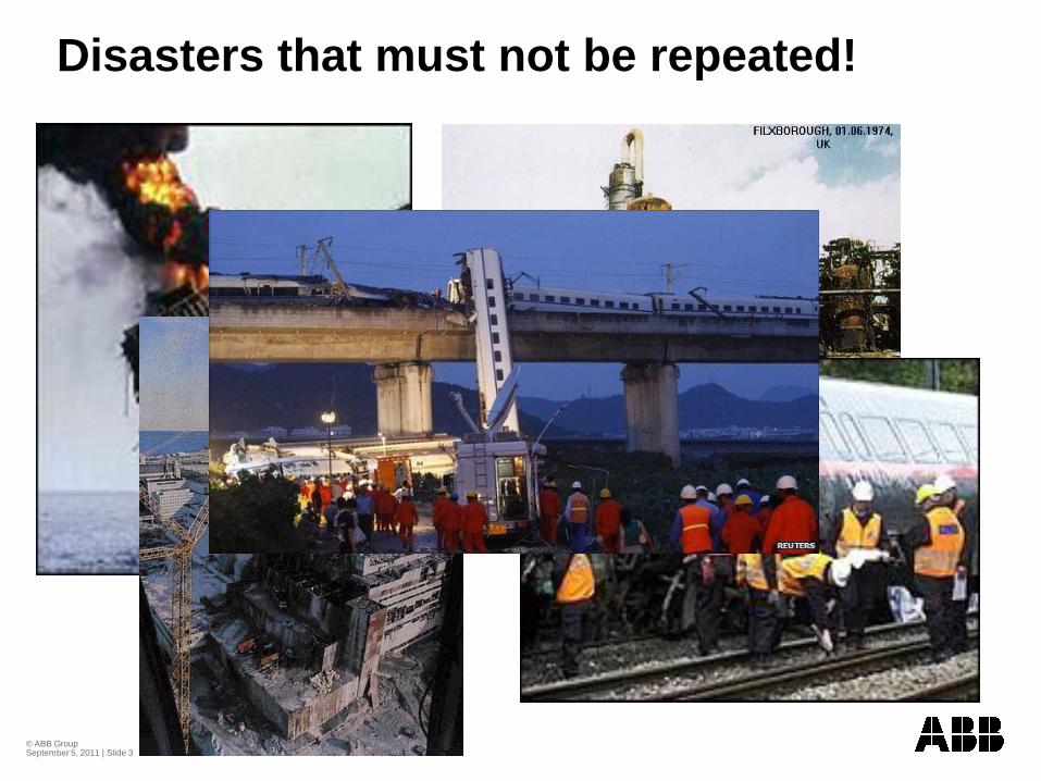
Disasters that must not be repeated!
© ABB Group September 5, 2011 | Slide 4
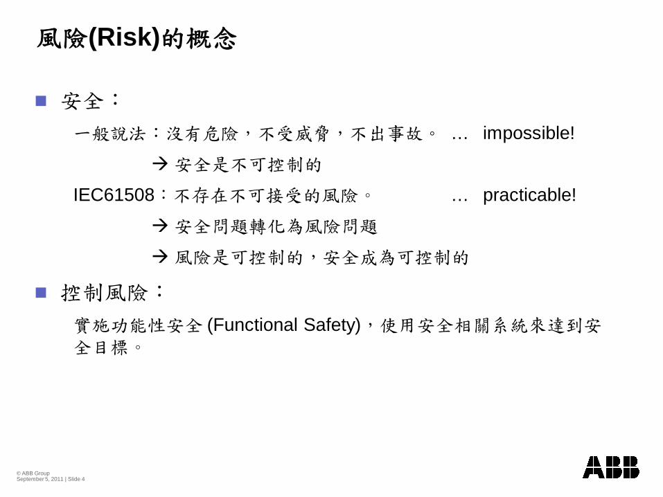
(Risk)
… impossible!
IEC61508 … practicable!
(Functional Safety)
© ABB Group September 5, 2011 | Slide 5
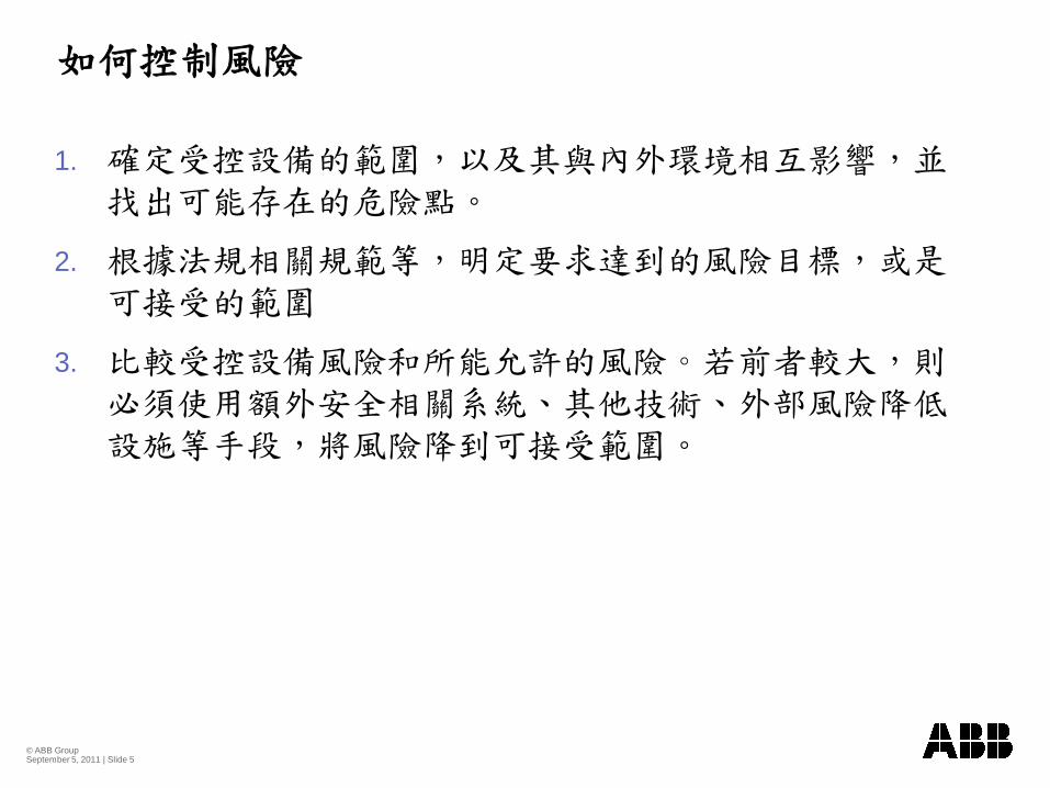
1.
2.
3.
© ABB Group September 5, 2011 | Slide 6
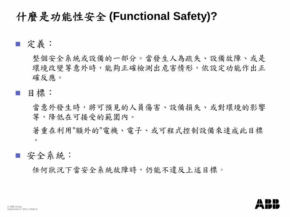
(Functional Safety)?
” ”
© ABB Group September 5, 2011 | Slide 7
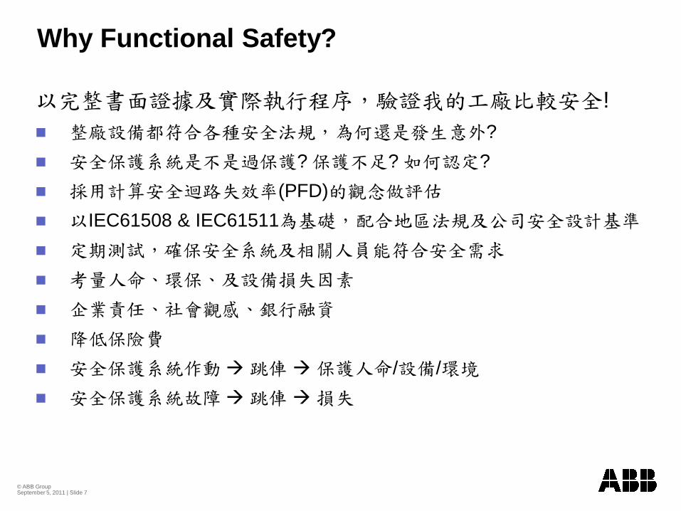
Why Functional Safety?
!?
? ? ?(PFD)
IEC61508 & IEC61511
/ /
© ABB Group September 5, 2011 | Slide 8
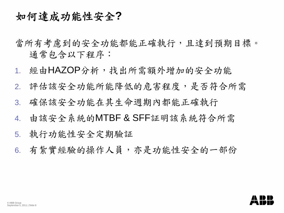
?
1. HAZOP
2.
3.
4. MTBF & SFF
5.
6.
© ABB Group September 5, 2011 | Slide 9
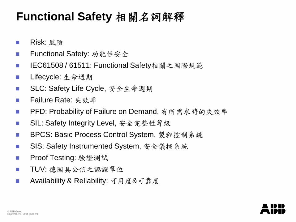
Functional Safety
Risk: Functional Safety: IEC61508 / 61511: Functional SafetyLifecycle: SLC: Safety Life Cycle, Failure Rate: PFD: Probability of Failure on Demand, SIL: Safety Integrity Level, BPCS: Basic Process Control System, SIS: Safety Instrumented System, Proof Testing: TUV: Availability & Reliability: &
© ABB Group September 5, 2011 | Slide 10
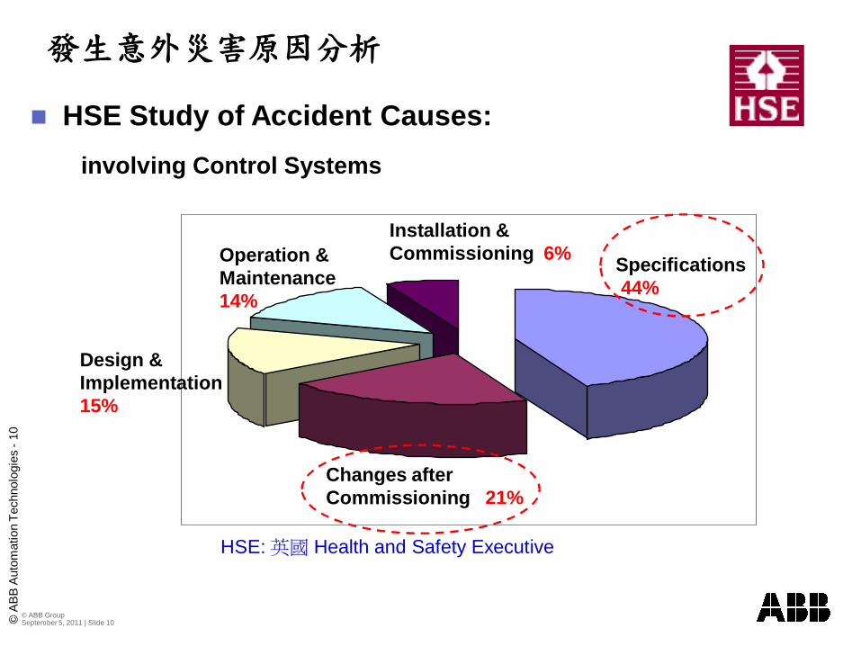
HSE Study of Accident Causes:involving Control Systems
© A
BB
Aut
omat
ion
Tech
nolo
gies
-10
Specifications 44%
Changes after Commissioning 21%
Design & Implementation15%
Operation & Maintenance 14%
Installation & Commissioning 6%
HSE: Health and Safety Executive
© ABB Group September 5, 2011 | Slide 11
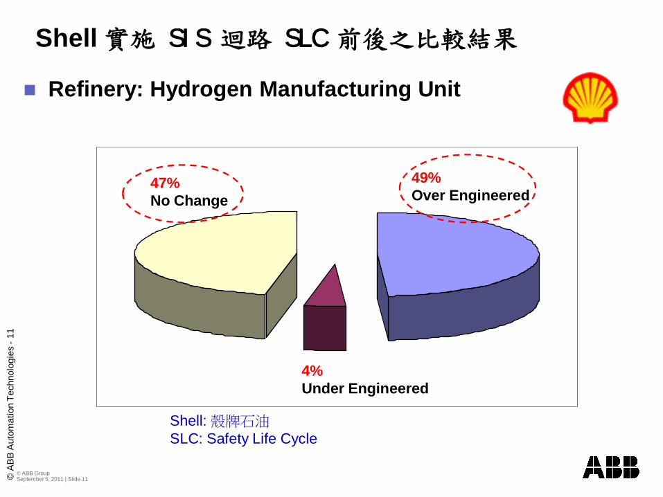
Refinery: Hydrogen Manufacturing Unit
Shell SIS SLC
© A
BB
Aut
omat
ion
Tech
nolo
gies
-11
49%Over Engineered
4%Under Engineered
47% No Change
Shell: SLC: Safety Life Cycle
© ABB Group September 5, 2011 | Slide 12
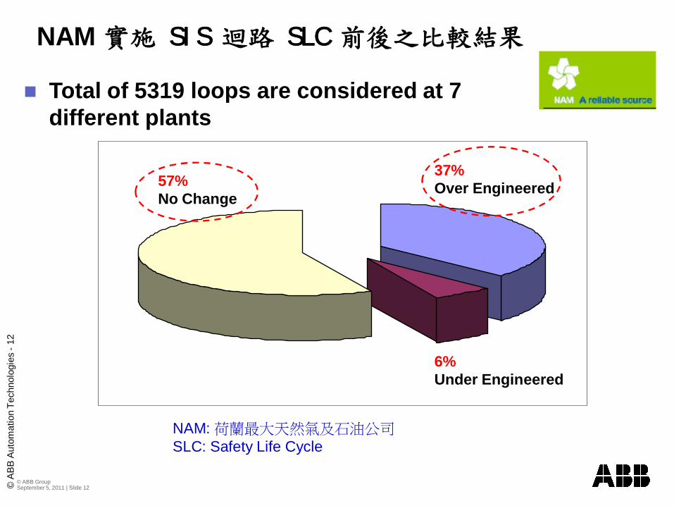
Total of 5319 loops are considered at 7 different plants
NAM SIS SLC ©
AB
B A
utom
atio
n Te
chno
logi
es -
12
37%Over Engineered
6%Under Engineered
57% No Change
NAM: SLC: Safety Life Cycle
© ABB Group September 5, 2011 | Slide 13
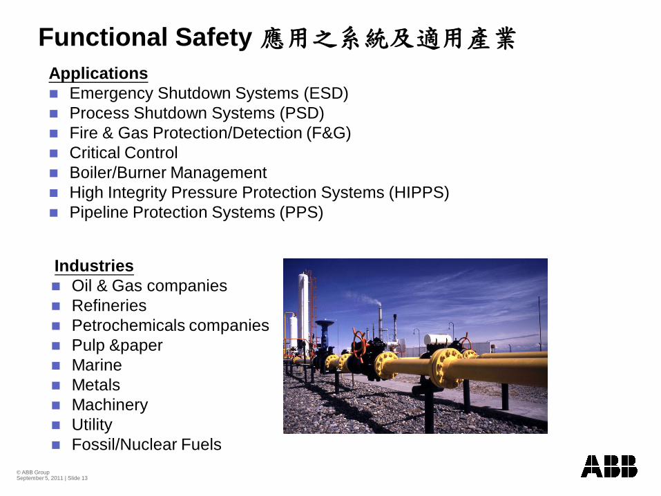
Functional Safety Applications
Emergency Shutdown Systems (ESD)Process Shutdown Systems (PSD)Fire & Gas Protection/Detection (F&G)Critical ControlBoiler/Burner ManagementHigh Integrity Pressure Protection Systems (HIPPS)Pipeline Protection Systems (PPS)
IndustriesOil & Gas companiesRefineriesPetrochemicals companiesPulp &paperMarineMetalsMachineryUtility Fossil/Nuclear Fuels
© ABB Group September 5, 2011 | Slide 14
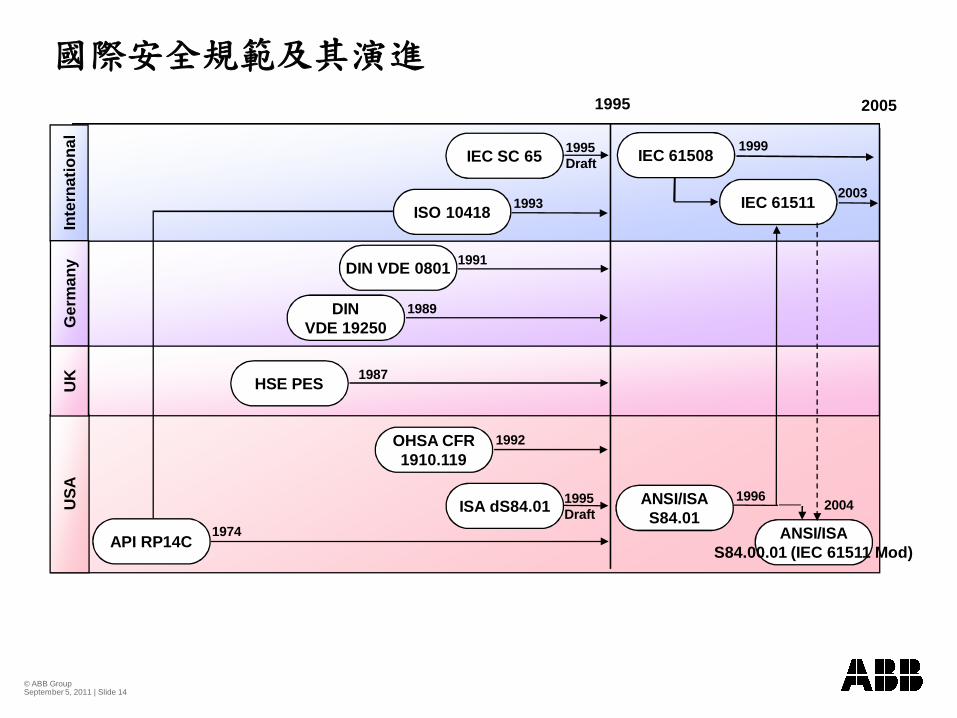
USA
Inte
rnat
iona
lG
erm
any
UK
1995
IEC SC 65 IEC 61508
ISO 10418
DIN VDE 0801
DINVDE 19250
HSE PES
OHSA CFR1910.119
ISA dS84.01
API RP14C
1995Draft
1995Draft
1993
1991
1989
1987
1974
ANSI/ISAS84.01
1999
2005
IEC 61511 2003
1996
1992
ANSI/ISAS84.00.01 (IEC 61511 Mod)
2004
© ABB Group September 5, 2011 | Slide 15
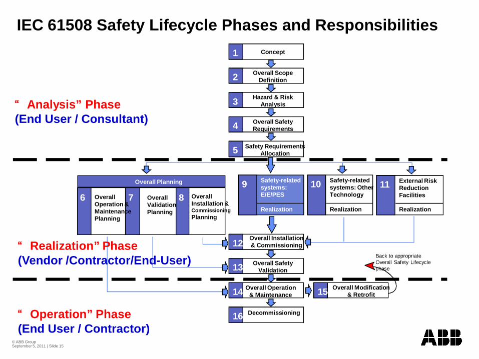
IEC 61508 Safety Lifecycle Phases and Responsibilities
11 External RiskReductionFacilities
Realization
1 Concept
2 Overall Scope Definition
3 Hazard & Risk Analysis
4 Overall Safety Requirements
5 Safety Requirements Allocation
15 Overall Modification & Retrofit
16 Decommissioning
12 Overall Installation & Commissioning
13 Overall Safety Validation
14 Overall Operation& Maintenance
9 Safety-relatedsystems: E/E/PES
Realization
10 Safety-relatedsystems: Other Technology
Realization
Overall Installation & Commissioning Planning
6 7 8Overall Operation & Maintenance Planning
Overall Validation Planning
Overall Planning
Back to appropriate Overall Safety Lifecycle phase
“Analysis” Phase(End User / Consultant)
“Realization” Phase(Vendor /Contractor/End-User)
“Operation” Phase(End User / Contractor)
© ABB Group September 5, 2011 | Slide 16
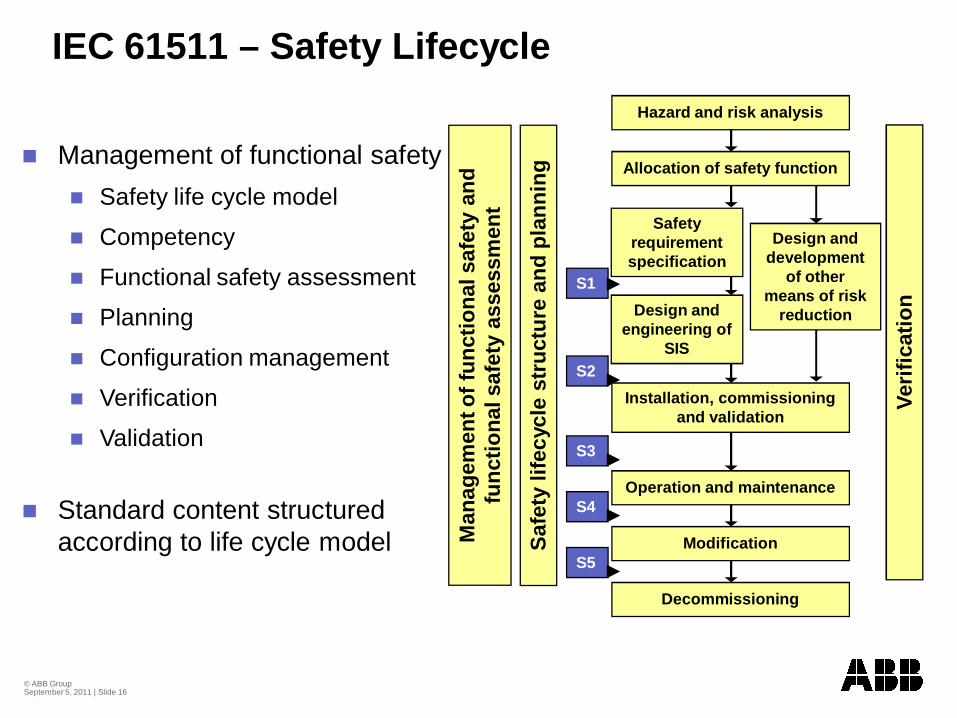
IEC 61511 – Safety Lifecycle
Verif
icat
ion
Safe
ty li
fecy
cle
stru
ctur
e an
d pl
anni
ng
Man
agem
ent o
f fun
ctio
nal s
afet
y an
d fu
nctio
nal s
afet
y as
sess
men
t
S1
S2
S3
S4
S5
Decommissioning
Hazard and risk analysis
Modification
Operation and maintenance
Installation, commissioning and validation
Safety requirement specification
Design and engineering of
SIS
Allocation of safety function
Design and development
of other means of risk
reduction
Management of functional safetySafety life cycle model
Competency
Functional safety assessment
Planning
Configuration management
Verification
Validation
Standard content structured according to life cycle model
© ABB Group September 5, 2011 | Slide 17
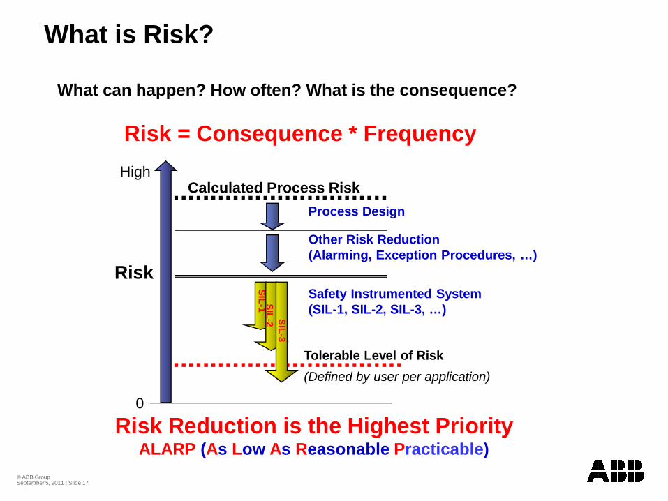
Calculated Process Risk
What is Risk?
Tolerable Level of Risk(Defined by user per application)
Risk
Process Design
Other Risk Reduction (Alarming, Exception Procedures, …)
Risk Reduction is the Highest PriorityALARP (As Low As Reasonable Practicable)
What can happen? How often? What is the consequence?
Risk = Consequence * Frequency
Safety Instrumented System (SIL-1, SIL-2, SIL-3, …)
SIL-1 SIL-2 SIL-3
0
High
© ABB Group September 5, 2011 | Slide 18
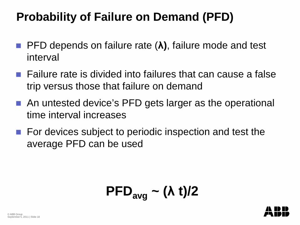
Probability of Failure on Demand (PFD)
PFD depends on failure rate ( ), failure mode and test interval
Failure rate is divided into failures that can cause a false trip versus those that failure on demand
An untested device’s PFD gets larger as the operational time interval increases
For devices subject to periodic inspection and test the average PFD can be used
PFDavg ~ ( t)/2
© ABB Group September 5, 2011 | Slide 19
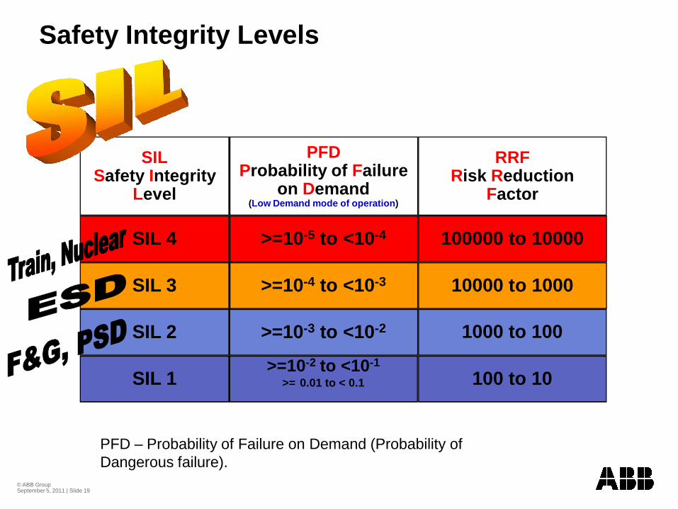
SILSafety Integrity
Level
SIL 4
SIL 3
SIL 2
SIL 1
PFDProbability of Failure
on Demand(Low Demand mode of operation)
RRFRisk Reduction
Factor
>=10-5 to <10-4
>=10-4 to <10-3
>=10-3 to <10-2
>=10-2 to <10-1
>= 0.01 to < 0.1
100000 to 10000
10000 to 1000
1000 to 100
100 to 10
Safety Integrity Levels
PFD – Probability of Failure on Demand (Probability of Dangerous failure).
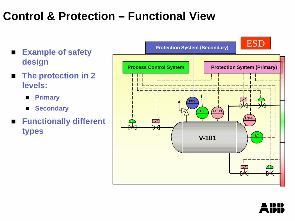
Example of safety designThe protection in 2 levels:
PrimarySecondary
Functionally different types
Control & Protection – Functional View
PSHHPT
LSHL
LT
PSV
Process Control System Protection System (Primary)
V-101
Protection System (Secondary) ESD
© ABB Group September 5, 2011 | Slide 21
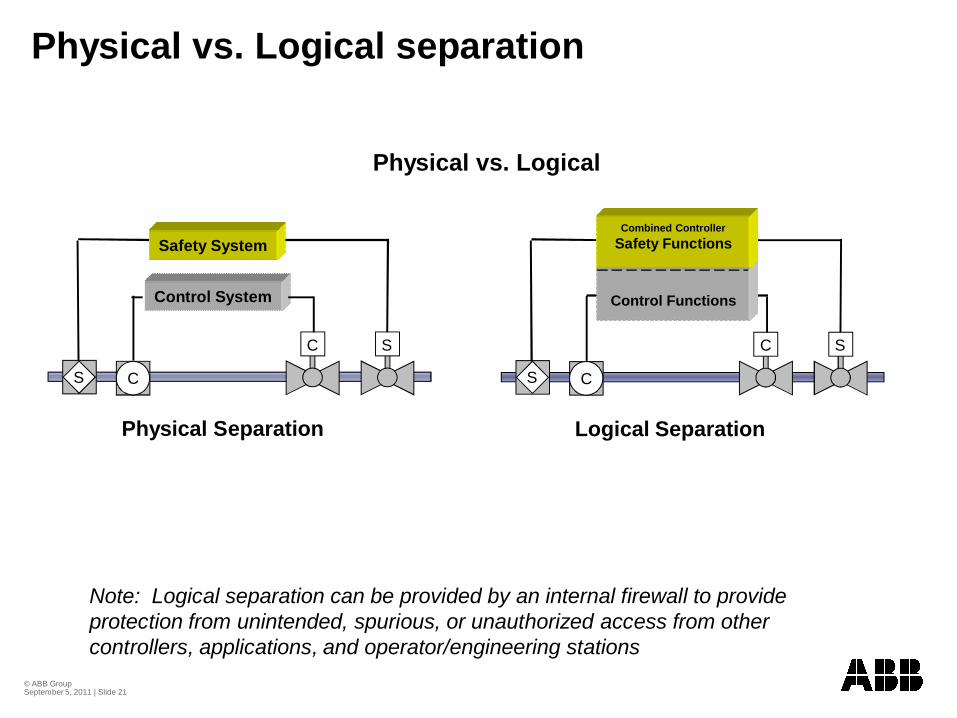
Physical vs. Logical separation
Physical vs. Logical
S C
C S
Physical Separation
S C
C S
Logical Separation
Note: Logical separation can be provided by an internal firewall to provide protection from unintended, spurious, or unauthorized access from other controllers, applications, and operator/engineering stations
Safety System
Control System Control Functions
Combined ControllerSafety Functions
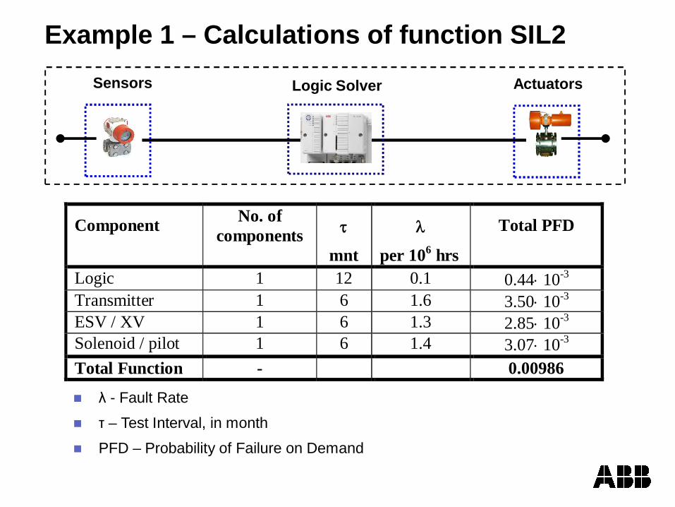
Example 1 – Calculations of function SIL2
Component No. of components
mnt
per 106 hrs
Total PFD
Logic 1 12 0.1 0.44 10-3 Transmitter 1 6 1.6 3.50 10-3 ESV / XV 1 6 1.3 2.85 10-3 Solenoid / pilot 1 6 1.4 3.07 10-3 Total Function - 0.00986 - Fault Rate
– Test Interval, in month
PFD – Probability of Failure on Demand
Logic SolverSensors Actuators
© ABB Group September 5, 2011 | Slide 23
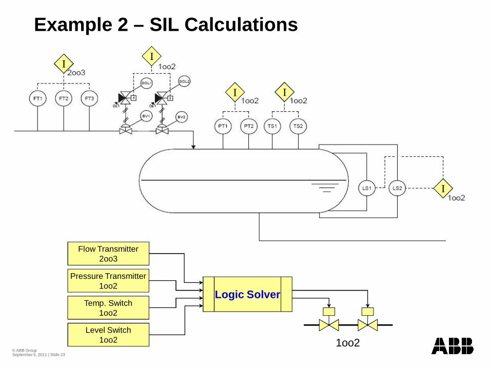
Example 2 – SIL Calculations
II
I I
I
Flow Transmitter2oo3
Pressure Transmitter1oo2
Temp. Switch1oo2
Level Switch1oo2
Logic Solver
1oo2
© ABB Group September 5, 2011 | Slide 24
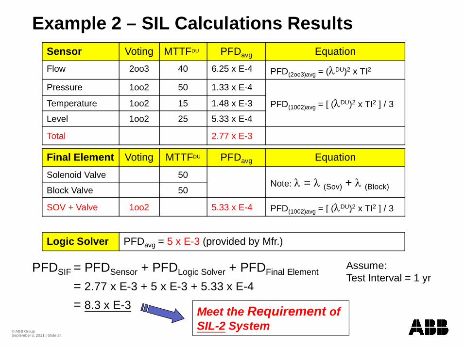
Example 2 – SIL Calculations ResultsSensor Voting MTTFDU PFDavg EquationFlow 2oo3 40 6.25 x E-4 PFD(2oo3)avg = ( DU)2 x TI2
Pressure 1oo2 50 1.33 x E-4
PFD(1002)avg = [ ( DU)2 x TI2 ] / 3Temperature 1oo2 15 1.48 x E-3
Level 1oo2 25 5.33 x E-4
Total 2.77 x E-3
Final Element Voting MTTFDU PFDavg EquationSolenoid Valve 50
Note: = (Sov) + (Block)Block Valve 50
SOV + Valve 1oo2 5.33 x E-4 PFD(1002)avg = [ ( DU)2 x TI2 ] / 3
Logic Solver PFDavg = 5 x E-3 (provided by Mfr.)
PFDSIF = PFDSensor + PFDLogic Solver + PFDFinal Element
= 2.77 x E-3 + 5 x E-3 + 5.33 x E-4= 8.3 x E-3 Meet the Requirement of
SIL-2 System
Assume:Test Interval = 1 yr
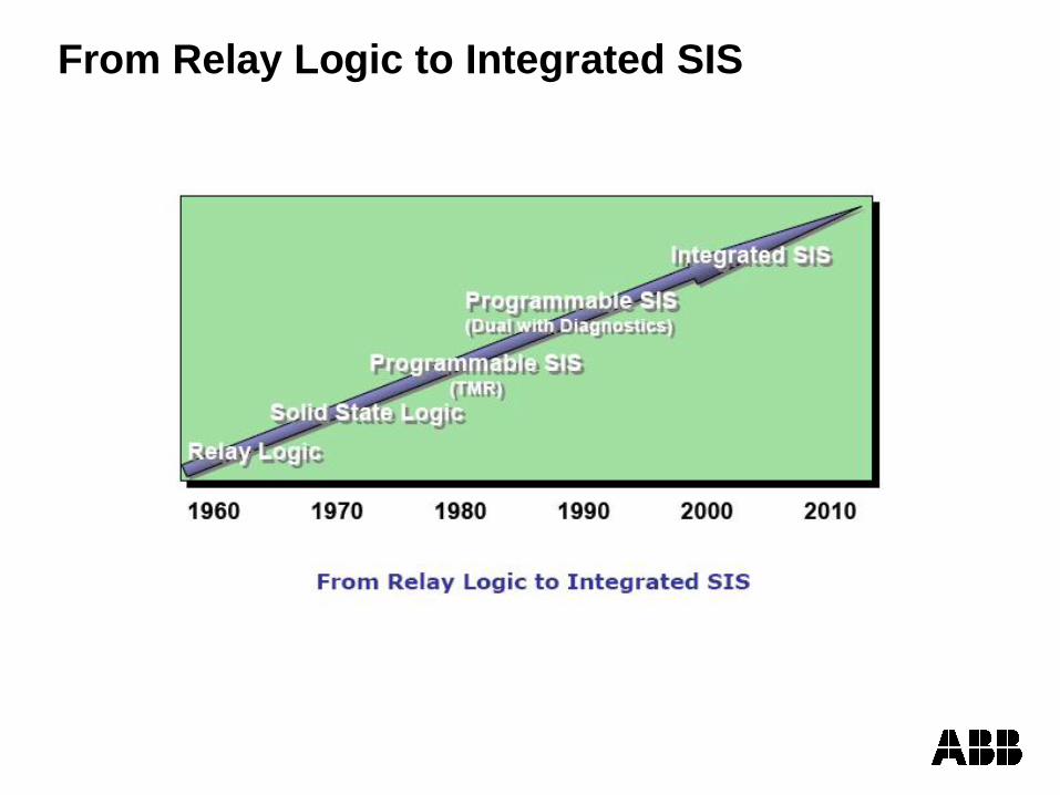
From Relay Logic to Integrated SIS
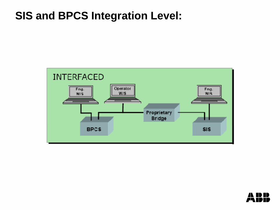
SIS and BPCS Integration Level:
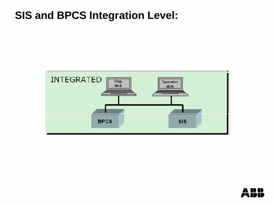
SIS and BPCS Integration Level:
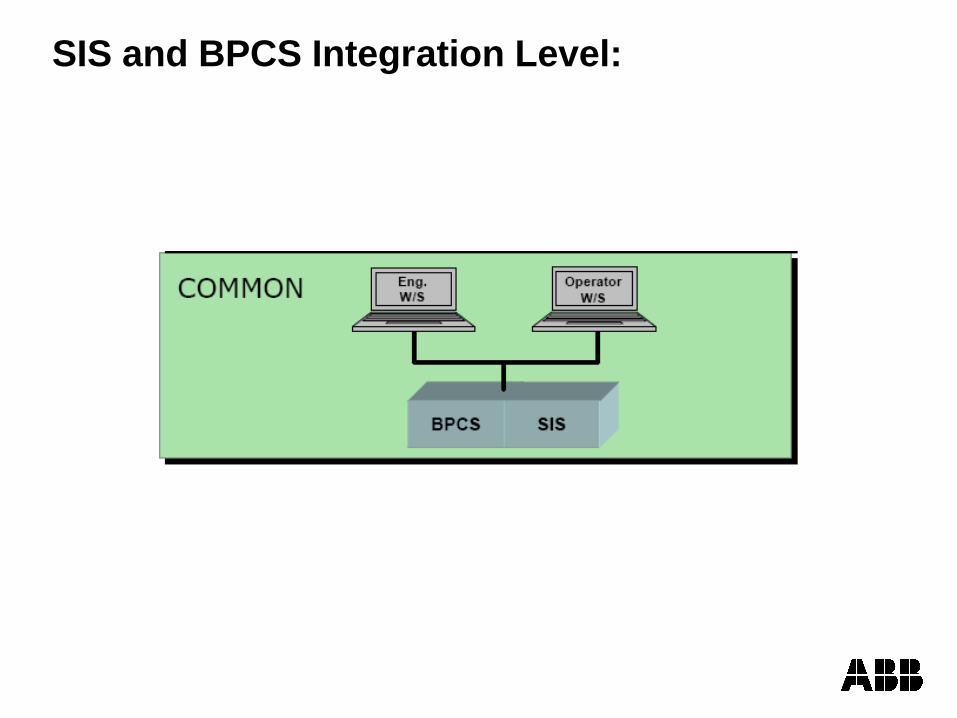
SIS and BPCS Integration Level:
© ABB Group September 5, 2011 | Slide 29
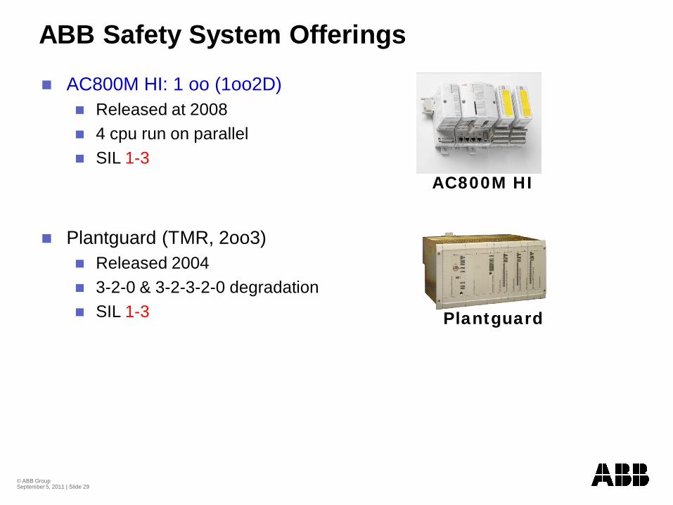
ABB Safety System Offerings
AC800M HI: 1 oo (1oo2D)Released at 20084 cpu run on parallelSIL 1-3
Plantguard (TMR, 2oo3)Released 20043-2-0 & 3-2-3-2-0 degradationSIL 1-3
AC800M HI
Plantguard
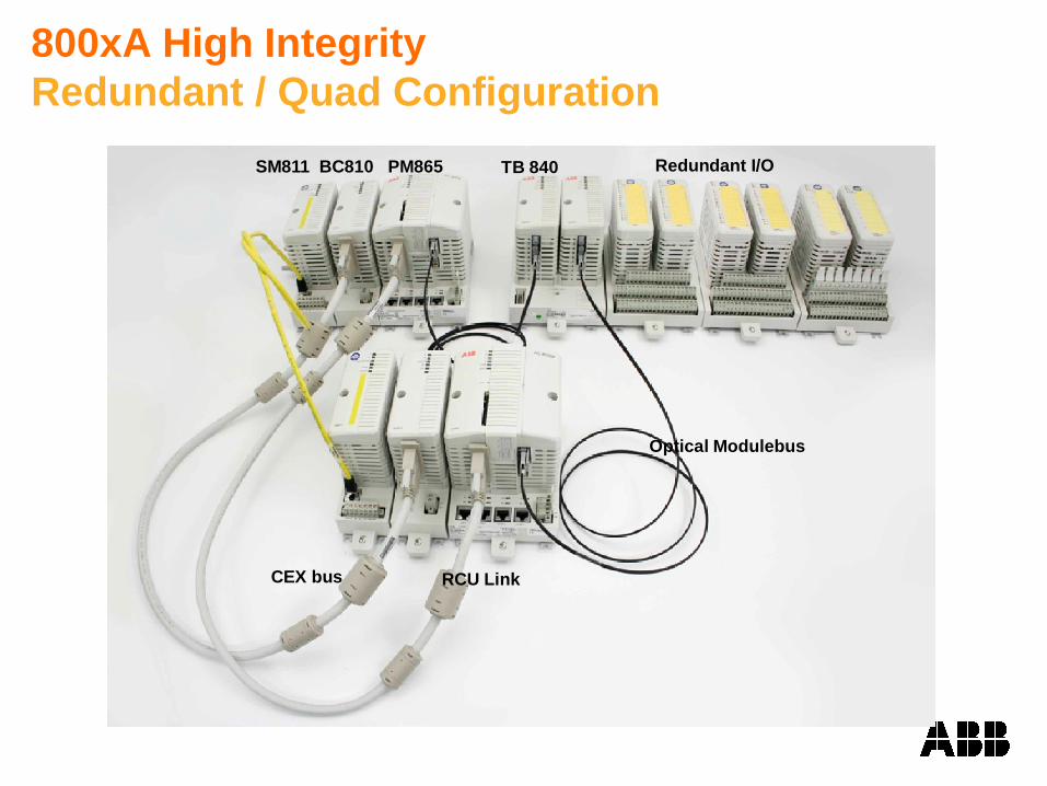
800xA High IntegrityRedundant / Quad Configuration
SM811 BC810 PM865
Optical Modulebus
RCU LinkCEX bus
Redundant I/OTB 840
© ABB Group September 5, 2011 | Slide 31
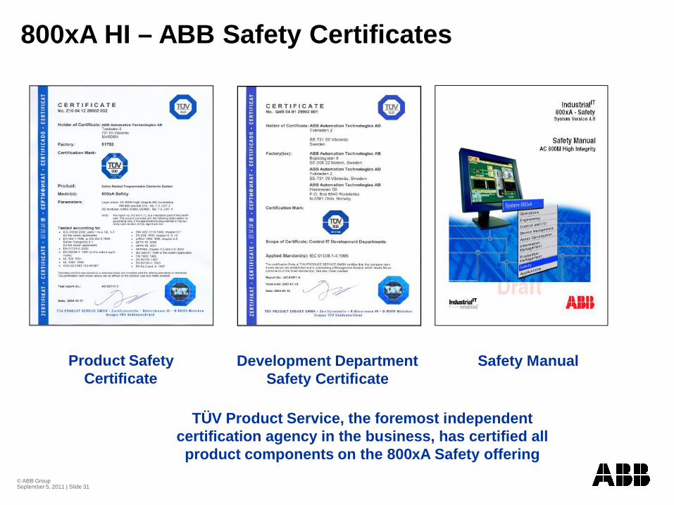
800xA HI – ABB Safety Certificates
TÜV Product Service, the foremost independent certification agency in the business, has certified all product components on the 800xA Safety offering
Product Safety Certificate
Development Department Safety Certificate
Safety Manual
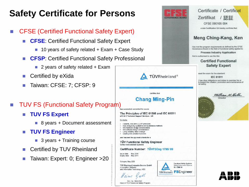
Safety Certificate for Persons
CFSE (Certified Functional Safety Expert)CFSE: Certified Functional Safety Expert
10 years of safety related + Exam + Case Study
CFSP: Certified Functional Safety Professional2 years of safety related + Exam
Certified by eXida
Taiwan: CFSE: 7; CFSP: 9
TUV FS (Functional Safety Program)TUV FS Expert
8 years + Document assessment
TUV FS Engineer3 years + Training course
Certified by TUV Rheinland
Taiwan: Expert: 0; Engineer >20
© ABB Group September 5, 2011 | Slide 33
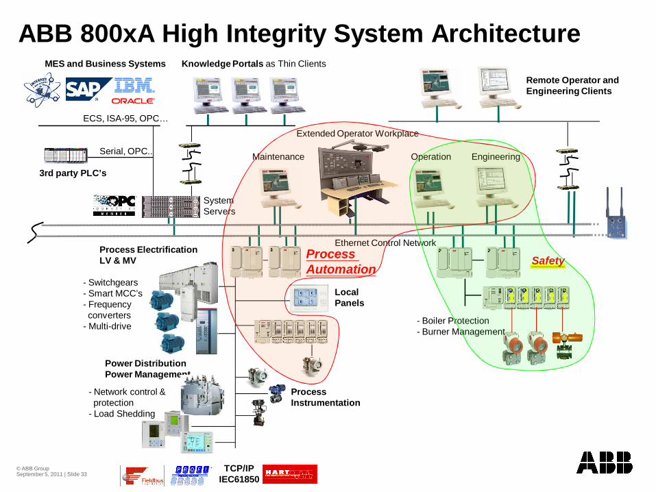
ABB 800xA High Integrity System Architecture
Power DistributionPower Management
Process ElectrificationLV & MV
Ethernet Control Network
Remote Operator andEngineering Clients
System Servers
Process Automation
Operation EngineeringMaintenance
Safety
Knowledge Portals as Thin ClientsMES and Business Systems
ECS, ISA-95, OPC…
3rd party PLC’s
Serial, OPC.. Operation
LocalPanels
ProcessInstrumentation
- Switchgears- Smart MCC’s- Frequencyconverters
- Multi-drive
- Network control & protection
- Load Shedding
TCP/IPIEC61850
- Boiler Protection- Burner Management
Extended Operator Workplace
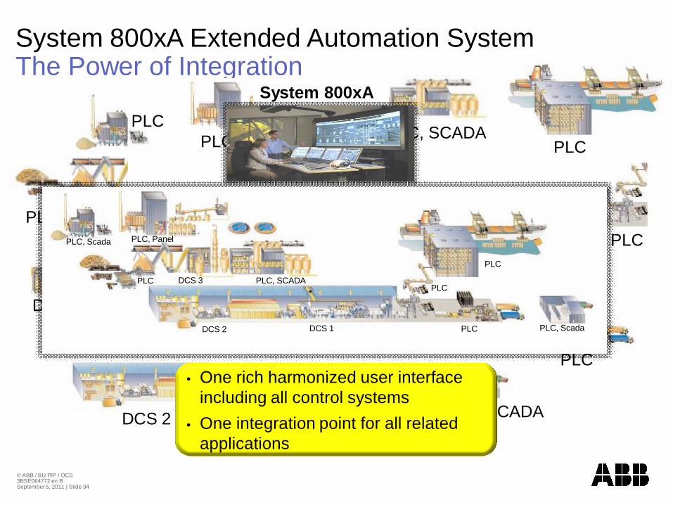
Situation TodayIslands of AutomationSystem 800xA Extended Automation System The Power of Integration
PLC
PLC, SCADADCS 1DCS 2
PLC, Panel
PLC, SCADA
PLC
DCS 3
PLC, SCADAPLC
PLC
PLC, ScadaPLCDCS 1DCS 2
PLC, PanelPLC, Scada
PLC DCS 3 PLC, SCADA
PLC
PLC
System 800xA
• One rich harmonized user interface including all control systems
• One integration point for all related applications
© ABB / BU PIP / OCS 3BSE064772 en BSeptember 5, 2011 | Slide 34
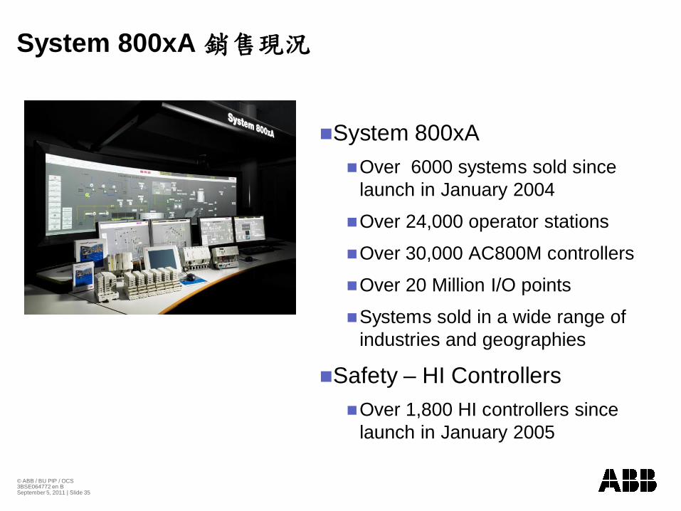
System 800xA
System 800xAOver 6000 systems sold since launch in January 2004
Over 24,000 operator stations
Over 30,000 AC800M controllers
Over 20 Million I/O points
Systems sold in a wide range of industries and geographies
Safety – HI ControllersOver 1,800 HI controllers since launch in January 2005
© ABB / BU PIP / OCS 3BSE064772 en BSeptember 5, 2011 | Slide 35
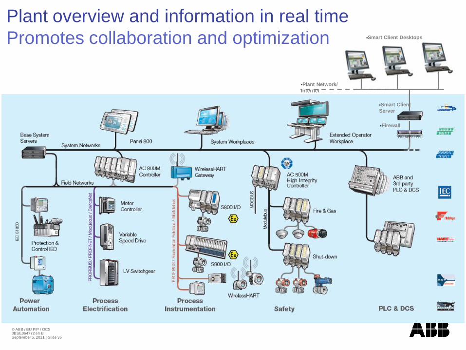
Plant Network/ Internet
Firewall
Smart Client Server
Smart Client Desktops
Plant overview and information in real time Promotes collaboration and optimization
© ABB / BU PIP / OCS 3BSE064772 en BSeptember 5, 2011 | Slide 36
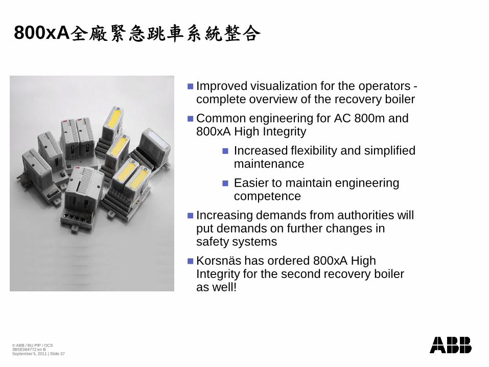
800xA
Improved visualization for the operators -complete overview of the recovery boiler Common engineering for AC 800m and 800xA High Integrity
Increased flexibility and simplified maintenanceEasier to maintain engineering competence
Increasing demands from authorities will put demands on further changes in safety systemsKorsnäs has ordered 800xA High Integrity for the second recovery boiler as well!
© ABB / BU PIP / OCS 3BSE064772 en BSeptember 5, 2011 | Slide 37
800xA
© ABB / BU PIP / OCS 3BSE064772 en BSeptember 5, 2011 | Slide 38
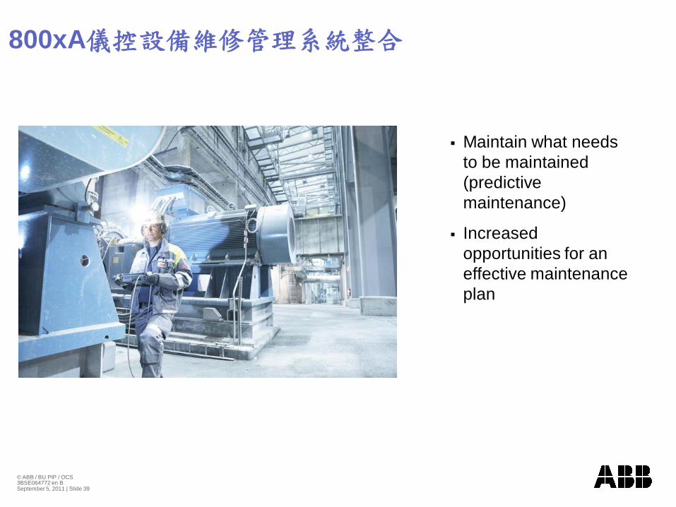
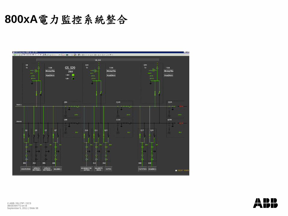
800xA
Maintain what needs to be maintained (predictive maintenance)
Increased opportunities for an effective maintenance plan
© ABB / BU PIP / OCS 3BSE064772 en BSeptember 5, 2011 | Slide 39
© ABB Group September 5, 2011 | Slide 40
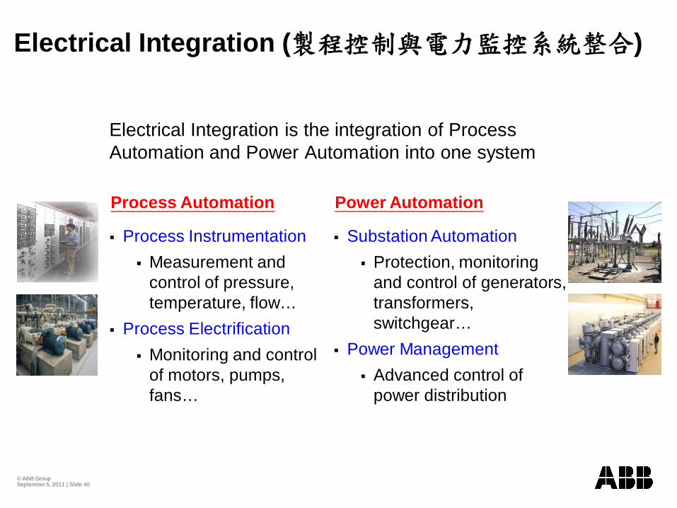
Electrical Integration ( )
Electrical Integration is the integration of Process Automation and Power Automation into one system
Process InstrumentationMeasurement and control of pressure, temperature, flow…
Process ElectrificationMonitoring and control of motors, pumps, fans…
Substation AutomationProtection, monitoring and control of generators, transformers, switchgear…
Power ManagementAdvanced control of power distribution
Process Automation Power Automation
© ABB Group September 5, 2011 | Slide 41
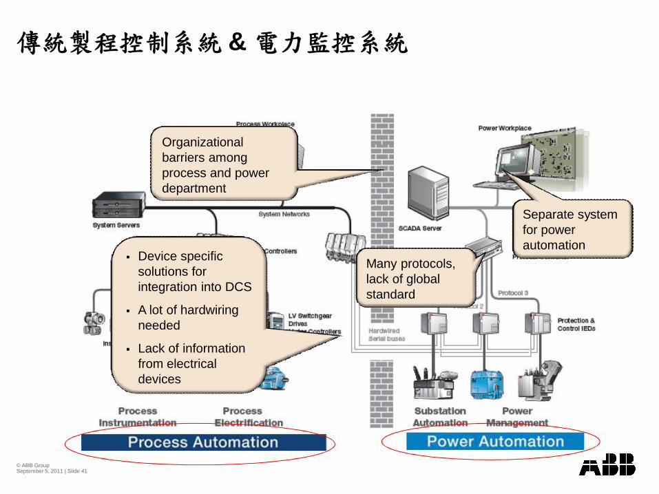
&
Many protocols, lack of global standard
Separate system for power automation
Organizational barriers among process and power department
Device specific solutions for integration into DCS
A lot of hardwiring needed
Lack of information from electrical devices
© ABB Group September 5, 2011 | Slide 42
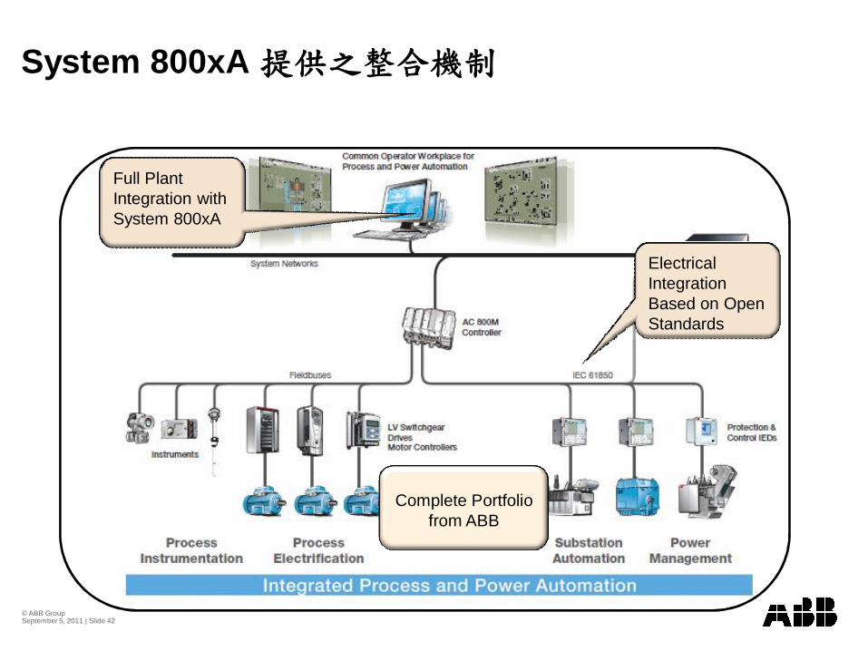
System 800xA
Electrical Integration Based on Open Standards
Full Plant Integration with System 800xA
Complete Portfolio from ABB
© ABB Group September 5, 2011 | Slide 43
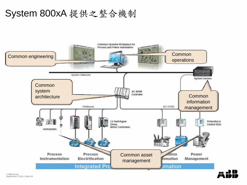
Common information
management
Centralized Historian and Data Archiving
Common asset management
Common system architecture
Common engineering Common operations
System 800xA
© ABB Group September 5, 2011 | Slide 44
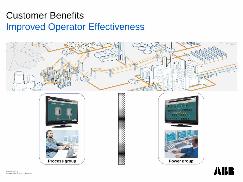
Customer BenefitsImproved Operator Effectiveness
Power groupProcess group
© ABB Group September 5, 2011 | Slide 45
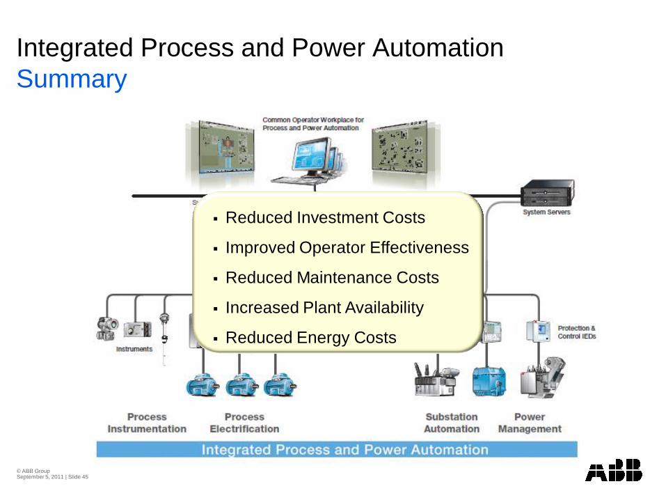
Integrated Process and Power AutomationSummary
Reduced Investment Costs
Improved Operator Effectiveness
Reduced Maintenance Costs
Increased Plant Availability
Reduced Energy Costs
© ABB Group September 5, 2011 | Slide 46
© ABB Group September 5, 2011 | Slide 47
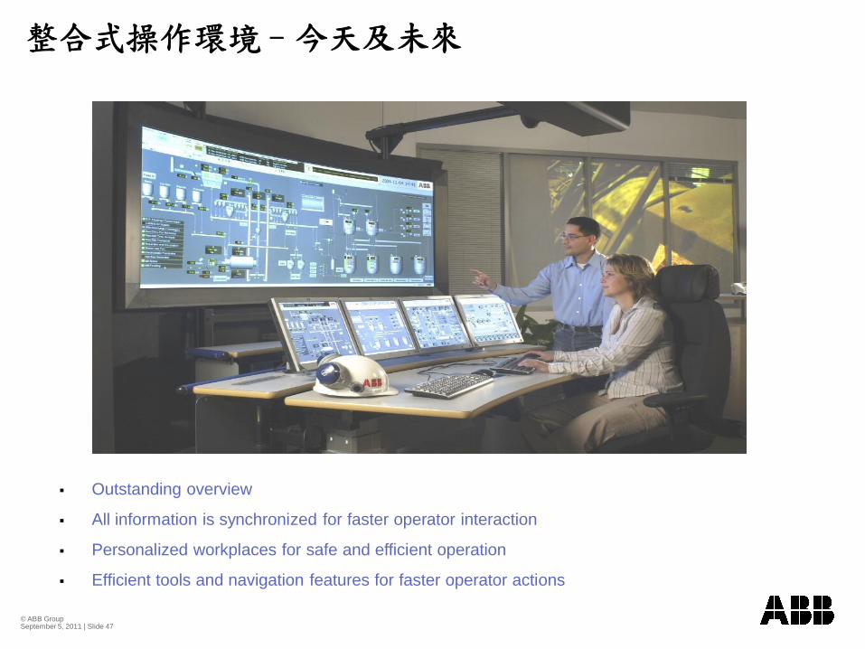
Outstanding overview
All information is synchronized for faster operator interaction
Personalized workplaces for safe and efficient operation
Efficient tools and navigation features for faster operator actions
© ABB Group September 5, 2011 | Slide 48
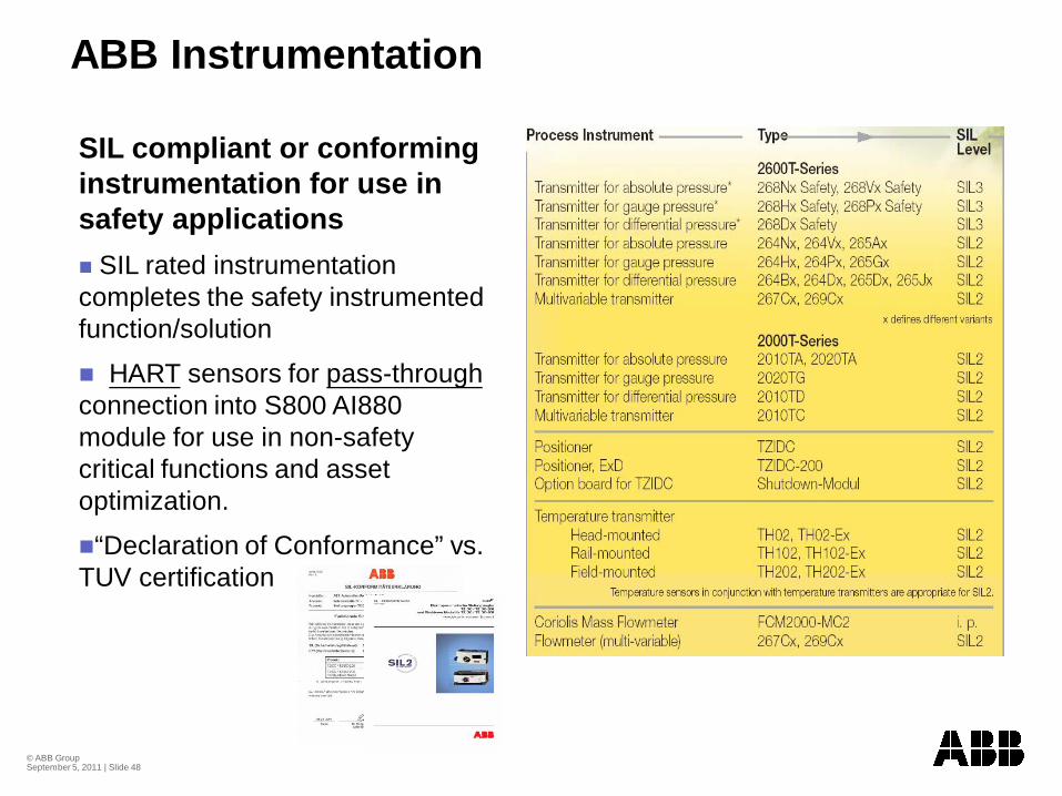
ABB Instrumentation
SIL compliant or conforming instrumentation for use in safety applications
SIL rated instrumentation completes the safety instrumented function/solution
HART sensors for pass-throughconnection into S800 AI880 module for use in non-safety critical functions and asset optimization.
“Declaration of Conformance” vs. TUV certification
© ABB Group September 5, 2011 | Slide 49
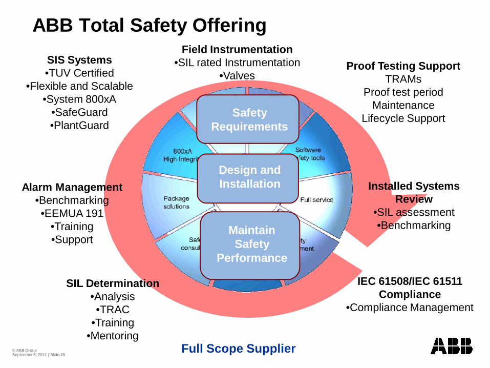
Installed Systems Review
•SIL assessment•Benchmarking
IEC 61508/IEC 61511 Compliance
•Compliance Management
SIL Determination•Analysis•TRAC
•Training•Mentoring
Alarm Management•Benchmarking •EEMUA 191
•Training•Support
ABB Total Safety Offering
Full Scope Supplier
SIS Systems•TUV Certified
•Flexible and Scalable•System 800xA
•SafeGuard•PlantGuard
Safety Requirements
Design and Installation
Maintain Safety
Performance
Field Instrumentation•SIL rated Instrumentation
•ValvesProof Testing Support
TRAMsProof test period
MaintenanceLifecycle Support
© ABB Group September 5, 2011 | Slide 50
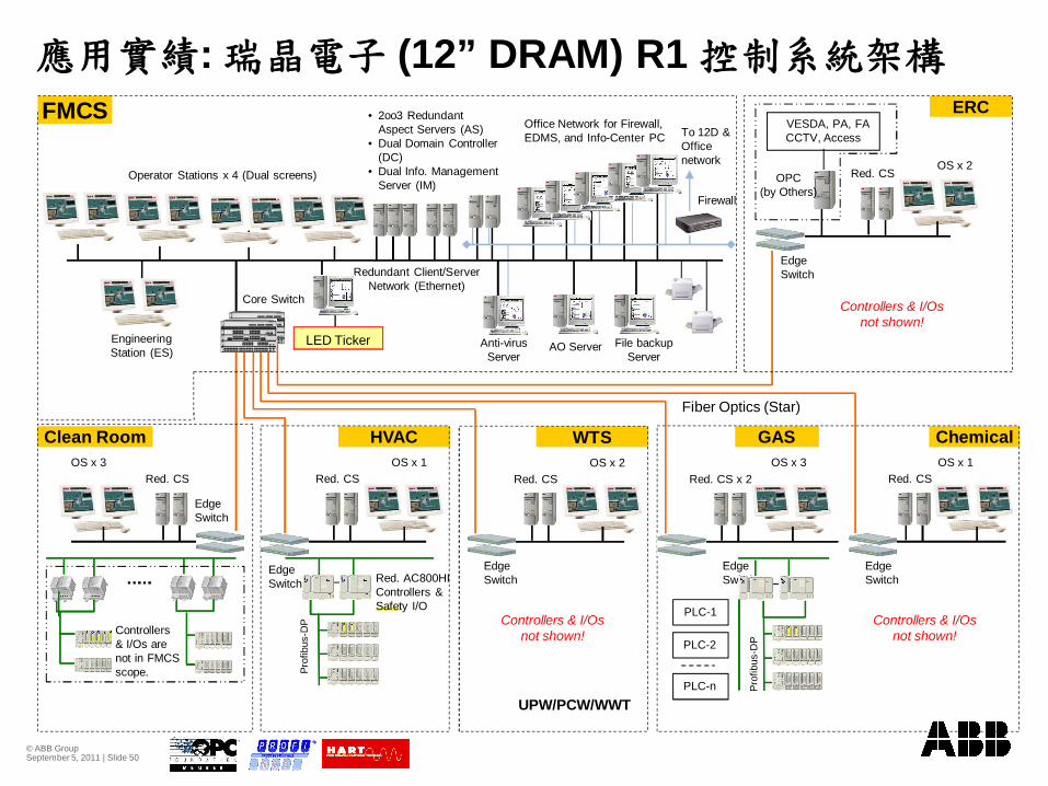
Anti-virus Server
Fiber Optics (Star)
Redundant Client/Server Network (Ethernet)
GAS
: (12” DRAM) R1
Chemical
ERC
Clean Room HVAC
FMCS
Operator Stations x 4 (Dual screens)
• 2oo3 Redundant Aspect Servers (AS)
• Dual Domain Controller (DC)
• Dual Info. Management Server (IM)
Office Network for Firewall, EDMS, and Info-Center PC
VESDA, PA, FACCTV, Access
EngineeringStation (ES)
Red. CS
LED Ticker
OS x 3OS x 3 OS x 1 OS x 1
Core Switch
Edge Switch
Edge Switch
OS x 2
Controllers & I/Os not shown!
Controllers & I/Os not shown!
Red. CS
Edge Switch
WTS
Red. CS
Controllers & I/Os not shown!
OS x 2Red. CS x 2
Edge Switch
Red. CS
Controllers & I/Os are not in FMCS scope.
Firewall
AO Server File backup Server
Red. CS
To 12D & Office network
OPC(by Others)
UPW/PCW/WWT
Edge Switch
Prof
ibus
-DP
Red. AC800HI Controllers & Safety I/O
PLC-2
PLC-n
PLC-1
Edge Switch
Prof
ibus
-DP
© ABB Group September 5, 2011 | Slide 51
![ ñ - Ä Òá - agape-wakamatsu.or.jp201408].… · ¹ $Ç « m 1 z ²  ñ - Ä Òá ¹ ü¢ Ê¢¢ z ¤ Ó ¹ üíÓ - Ä + ô Ï S ú ÷ ¢ - Ä¢](https://img.pdfslide.tips/doc/110x75/5b9d48c209d3f2ed218be251/a-n-ae-oa-agape-201408-c-m-1-z-a-n-ae-oa-ue.jpg)

![¨ ½ Ñ » µ ´ Ú · ÖÀ° ZnÀÅZ]ÖËÁ ZËÁ ÇÂÌ { Y~³½Â¿Z«¾Ë{ZÌÀ]ÕZÅ ÁZ]Ö¸neÕ ¨Ì ½Â¿Z« ¯ Ä]|ËZ]0Ó YY mYÁ Õ Z´//¿Y¹ m ¶uY »¹Z¼e {Ä ,d](https://img.pdfslide.tips/doc/110x75/5f0777037e708231d41d1d80/-znz-z-oe-yzzoez.jpg)


![XK ]í ðtmMoS tQ` b{...t b w ÿ UK Ôù tSMofzw ÿ t loC O^ h y Ú -e q \- tb w t 0b y Ú -e w ; U -e z wÀ ¿t HÄ ¤t lh .w Ë tI¼b y Ú ê zw â æ z µ Ëz SV c z º Zz â ÷](https://img.pdfslide.tips/doc/110x75/60490202c042635c072c0a37/xk-tmmos-tq-b-t-b-w-uk-tsmofzw-t-loc-o-h-y-e-q-tb.jpg)


![WISCï¼ â £ç ä¿®ä¼ â ¡...Þ 8 £\Á b\é } a ô j T ]I]d]S]]1]T]! Ú Z 5](https://img.pdfslide.tips/doc/110x75/5e3a9b1f850c307e5f39cefe/wisc-8-b-a-j-t-ids1t-.jpg)