Embed Size (px)
Citation preview

��������������� �� ��
������������ �� � ���������� �
Power on ProtectionFault
Power on ProtectionFault
Power on ProtectionFault
Power on ProtectionFault
Power onProtectionFault
����������������������������������

�������������������
__________________________
���������������������������������� ������ �� �!�
"������
This is the Installation and commissioning manual for Softstarters PST30...PSTB1050
Document number: 1SFC132003M0201
Edition: 01
Revision: 01
Issue date: 2003-03-20
Data subject to change without notice.
We reserve all rights to this document, even in the event that a patent is issued and a different commercial proprietary right is registered. Improper use, in particular reproduction and dissemination to third parties, is not permitted.
This document has been carefully checked. If the user nevertheless detects any errors, he is kindly asked to notify us as soon as possible.
The data contained in this manual is intended solely for the product description and is not to be deemed to be a statement of guaranteed properties. In the interests of our customers, we constantly seek to ensure that our products are developed to the latest technological standards.
As a result, it is possible that there may be some differences between the softstarter and this information product.
#�����$���������
ABB Automation Technology Products AB, ControlS-721 61 VästeråsSwedenTel: +46 (0) 21 32 07 00Fax: +46 (0) 21 60 01
http://www.abb.com/lowvoltage
© ABB Automation Technology Products AB, Control
31SFC132003M0201
% ������
This chapter describes warning and information signs used in this manual, which the user should pay attention to.The softstarter shall be installed by authorised personnel only.This manual is a part of the softstarter and should always be accessible for personnel working with this product.The manual shall always be read through before performing any installation or commissioning tasks.
� �����������
�� &�����������'(������'��������������
�������)
��������������������� ��������������� ������ � �������������������������������
(������)
��������������������� ��������������� ������ � ��������������������������������������������������������������������
�������������� ����������������������������������������
4 1SFC132003M0201
������� ���
��������
������������ *
% +���,����� �
� -���������� *
. /������� �
! ���������� �*
0 1����2/���������������31/�4 .5
* ������������������������ 0
6 7��������������������3������4 5*
5 /���������� �
�7�������� *
�������������� !*
%-������� 0*
�����8 *
���������������,������
51SFC132003M0201

9�����������������������������������������������������������������������������
�������������������������������������������������������������������������������������
�������������������������������������������������������������������������������������
�������������������������������������������������������������������������������������
�������������������������������������������������������������������������������������
�������������������������������������������������������������������������������������
�������������������������������������������������������������������������������������
�������������������������������������������������������������������������������������
�������������������������������������������������������������������������������������
�������������������������������������������������������������������������������������
�������������������������������������������������������������������������������������
�������������������������������������������������������������������������������������
�������������������������������������������������������������������������������������
�������������������������������������������������������������������������������������
�������������������������������������������������������������������������������������
�������������������������������������������������������������������������������������
�������������������������������������������������������������������������������������
1SFC132003M02016

������������
������� ������������
About the complete set of documentation for a softstarter .................................. 9
About the installation and commissioning manual............................................... 9
Intended audience .......................................................................................... 9General...................................................................................................... 9Requirements ............................................................................................ 9
Chapters included......................................................................................... 10Revision notes .............................................................................................. 10Acronyms and abbreviations ........................................................................ 11
71SFC132003M0201

8 1SFC132003M0201
������������
�������
������� ������������
� #������������������������������������������������
For the softstarter, the following documents are available:
�� ������������������������������������������������-��������-� �7� �%���/�%�
����������������������������-��������-� �7� �%�� ��%�
For other documents related to the PST Softstarters, see home page www.abb.com/lowvoltage
�% #�����������������������������������������
This manual contains instructions on how to install and commission the softstarter. The manual covers procedures for mechanical and electrical installation and installation of communication devices. It also covers energising, setting and configuration and verifying settings.For quickest possible start read Chapter 2 “Quickstart” .
�%� ����������������
�%� � "������The installation and commissioning manual is intended for the installation, commissioning and maintenance personnel responsible for putting the softstarter into normal service and out of service.
�%� �% :�;���������The installation personnel must have a basic knowledge inhandling electric equipment. The commissioning and maintenance personnel must be well experienced in using this kind of equipment.
91SFC132003M0201
�������������������
�%�% ����������������
• ����������� introduces the reader to this manual.• ��������� contains information on how to, in the
quickest way, install the softstarter and put it into oper-ation. This chapter is intended for the experienced user.
• ��������� describes the softstarter in general, its functions and specifications.
• ������� contains information on receiving, unpack-ing and mounting the softstarter.
• ��������� contains instructions on how to make the electrical connections as well as connections for com-munication devices.
• ��������������������� describes the local Human-Machine Interface, how it works and what it contains.
• ��������������������� describes all possible set-tings and how to navigate in the menu system.
• �� ���������������describes how to install and set up the fieldbus communication.
• ���������� describes what maintenance is needed.• �������� describes all functions included in the soft-
starter, as well as the available minimum and maxi-mum values and default values used.
• ����� �������� contains instructions on how to quickly find and correct the most common faults.
• ������� contains a number of electrical diagrams for the softstarter itself, and also some typical application diagrams.
�%�� :�<����������
Please check home page===�����������=<������for latest information on revisions.
10 1SFC132003M0201
������������
�������
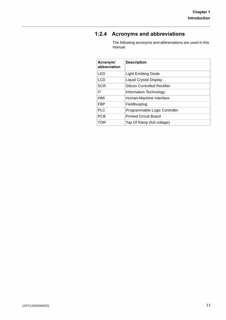
�%�. #���������������<�������
The following acronyms and abbreviations are used in this manual.
#������������<������
-����������
LED Light Emitting Diode
LCD Liquid Crystal Display
SCR Silicon Controlled Rectifier
IT Information Technology
HMI Human-Machine Interface
FBP Fieldbusplug
PLC Programmable Logic Controller
PCB Printed Circuit Board
TOR Top Of Ramp (full voltage)
111SFC132003M0201

�������������������
12 1SFC132003M0201

+���,�����
�������%+���,�����
Connection ........................................................................................................ 15
Configuration ..................................................................................................... 16
Start of the motor............................................................................................... 16
1SFC132003M020113

1SFC132003M020114
+���,�����
�������%
�������%+���,�����
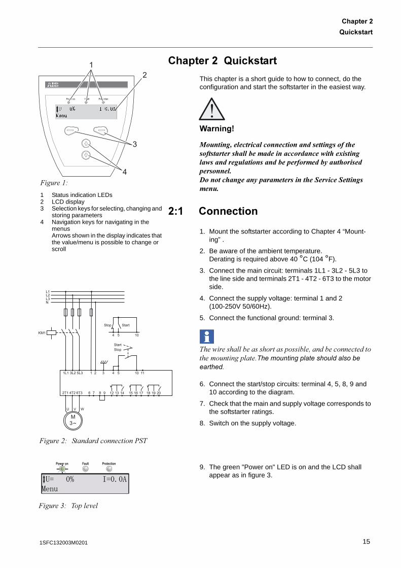
This chapter is a short guide to how to connect, do the configuration and start the softstarter in the easiest way.
(������)
�������������������������������������������� ��������������� ������������������������ ��������������������������������������������������� ���������������� ������ ������������������������ ��!��"���!�������������
%� ����������
1. Mount the softstarter according to Chapter 4 “Mount-ing” .
2. Be aware of the ambient temperature. Derating is required above 40 °C (104 °F).
3. Connect the main circuit: terminals 1L1 - 3L2 - 5L3 to the line side and terminals 2T1 - 4T2 - 6T3 to the motor side.
4. Connect the supply voltage: terminal 1 and 2 (100-250V 50/60Hz).
5. Connect the functional ground: terminal 3.
��� ����� ���������������� �!��������������������������� ���������������� ������� ��� �������������
6. Connect the start/stop circuits: terminal 4, 5, 8, 9 and 10 according to the diagram.
7. Check that the main and supply voltage corresponds to the softstarter ratings.
8. Switch on the supply voltage.
9. The green "Power on" LED is on and the LCD shall appear as in figure 3.
Power on ProtectionFault
1
2
3
4
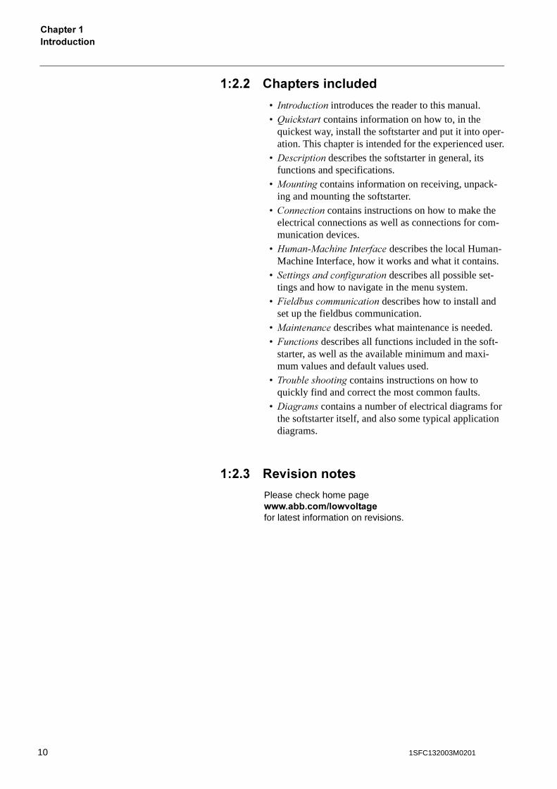
�����"#
1 Status indication LEDs2 LCD display3 Selection keys for selecting, changing and
storing parameters4 Navigation keys for navigating in the
menusArrows shown in the display indicates that the value/menu is possible to change or scroll
�� ��� ������
��
L1L2L3N
KM1
1L1 3L2 5L3
2T1 4T2 6T3 6 7 8 9 12 13 14 15 16 17 18 19 20
U V W
1 2 3 4 5 10
4 5 10
11
M
3
Stop Start
Stop
Start
�����$# �����������������%��
Power on ProtectionFault
�����&# ��� �'�
�� ��� ��������
151SFC132003M0201
Configuration+���,������������%
%�% �������������
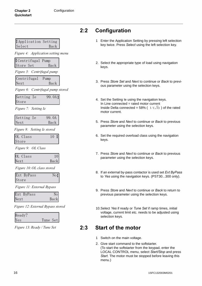
1 Enter the Application Setting by pressing left selection key twice. Press �� �� using the left selection key.
2. Select the appropriate type of load using navigation keys.
3. Press ������� and ���t to continue or ���� to previ-ous parameter using the selection keys.
4. Set the Setting Ie using the navigation keys.In Line connected = rated motor currentInside Delta connected = 58% ( ) of the rated motor current.
5. Press ���� and ��� to continue or ���� to previous parameter using the selection keys.
6. Set the required overload class using the navigation keys.
7. Press ���� and ��� to continue or ���� to previous parameter using the selection keys.
8. If an external by-pass contactor is used set ��������� to ����using the navigation keys. (PST30...300 only).
9. Press ���� and ��� to continue or ���� to return to previous parameter using the selection keys.
10.Select ��� if ready or ������� if ramp times, initial voltage, current limit etc. needs to be adjusted using selection keys.
%�� ���������������
1 Switch on the main voltage.
2. Give start command to the softstarter.(To start the softstarter from the keypad, enter the LOCAL CONTROL menu, select ������� and press ���. The motor must be stopped before leaving this menu.)
� ������������������� ����
�����(# )�� ���������������
���������� ��� ������� ����
�����*# ��������� ����
���������� ��� ��� ����
�����+# ��������� ����������
��������� ���������
�����,# �������� 1 3� ��
��������� �������� ����
�����-# ��������������
!����"" #�����
�����.# /0� ���
!����"" #���� ����
�����"1#/0� ���������
$����%��"" ������
�����""# 23����� 45����
$����%��"" ����� ����
�����"$#23����� 45����������
&�'%()" *�����
�����"���57�������
16 1SFC132003M0201
-����������
��������-����������
Overview............................................................................................................ 19
Functions ........................................................................................................... 20
Markings and connections................................................................................. 22
Type designation ............................................................................................... 23
Industrial IT........................................................................................................ 23
Environmental influence .................................................................................... 24
Specifications .................................................................................................... 24
Technical data ................................................................................................... 25
General......................................................................................................... 25Softstarter types ........................................................................................... 26Weights......................................................................................................... 27Dimensions................................................................................................... 28
171SFC132003M0201

18 1SFC132003M0201
-����������
��������
��������-����������
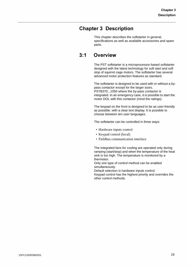
This chapter describes the softstarter in general, specifications as well as available accessories and spare parts.
�� ><��<��=
The PST softstarter is a microprocessor-based softstarter designed with the latest technology for soft start and soft stop of squirrel cage motors. The softstarter has several advanced motor protection features as standard.
The softstarter is designed to be used with or without a by-pass contactor except for the larger sizes, PSTB370...1050 where the by-pass contactor is integrated. In an emergency case, it is possible to start the motor DOL with this contactor (mind the ratings).
The keypad on the front is designed to be as user-friendly as possible, with a clear text display. It is possible to choose between ten user languages.
The softstarter can be controlled in three ways:
• Hardware inputs control• Keypad control (local)• Fieldbus communication interface
The integrated fans for cooling are operated only during ramping (start/stop) and when the temperature of the heat sink is too high. The temperature is monitored by a thermistor.Only one type of control method can be enabled simultaneously. Default selection is hardware inputs control. Keypad control has the highest priority and overrides the other control methods.
191SFC132003M0201
-������������������
��% 7��������
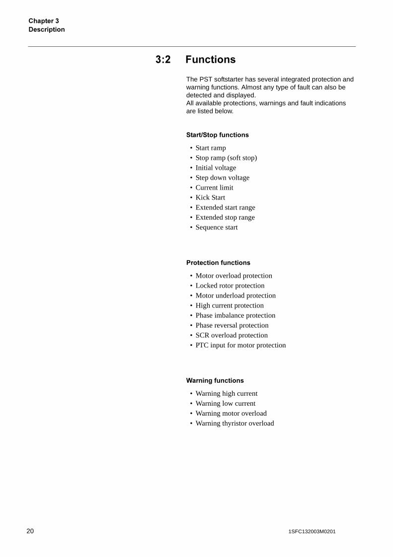
The PST softstarter has several integrated protection and warning functions. Almost any type of fault can also be detected and displayed. All available protections, warnings and fault indications are listed below.
�������������������
• Start ramp• Stop ramp (soft stop)• Initial voltage• Step down voltage• Current limit• Kick Start• Extended start range• Extended stop range• Sequence start
������������������
• Motor overload protection• Locked rotor protection• Motor underload protection• High current protection• Phase imbalance protection• Phase reversal protection• SCR overload protection• PTC input for motor protection
(���������������
• Warning high current• Warning low current• Warning motor overload• Warning thyristor overload
20 1SFC132003M0201
-����������
��������
7���������<��������������
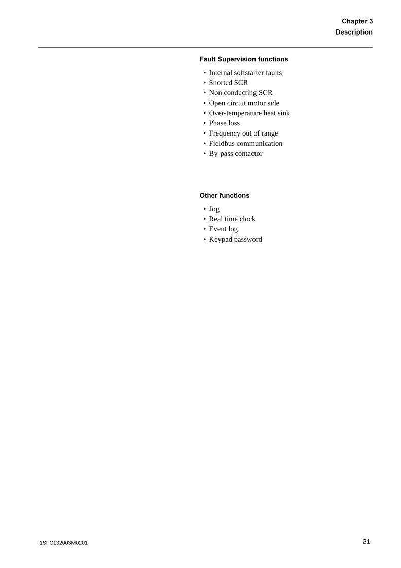
• Internal softstarter faults• Shorted SCR• Non conducting SCR• Open circuit motor side• Over-temperature heat sink• Phase loss• Frequency out of range• Fieldbus communication• By-pass contactor
>�������������
• Jog• Real time clock• Event log• Keypad password
211SFC132003M0201
-������������������
��� /��,������������������
1SFA 894 007 R1002
Ie: 37-72A
UL 508Uc: 100-250V AC/DC
FLA: 37-68A
Made in Sweden
Ue 208 220-240 440-480 V
In line 20 20 50 Hp
CAUTION Fuse 250A TYPOWER ZILOXMax short circuit current 65kA at 480V Wire 1-8 Al Cu 75C only, 35lb-in
Overload Capacity 115% of Continuous
1 2 3 4 5 6 7 8 9 10 11 12 13 14 15 16 17 18 19 20
100-250VL N
Stop Start In1 Vc Vn Vp Vp K4 In050/60 Hz K5 K6
PTCKeypad Fieldbus
1L1
2T1 4T2 6T3
B1 B2 B33L2 5L3
LISTEDIND. CONT. EQ
7F39
IEC 947-4-2Us: 100-250V AC/DC Ue: 220-230 380-400 500 V
72: AC-53a: 8-1.6: 80-6In line 18,5 37 45 kW
LISTED 7F39IND. CONT. EQ.
Ie: 37-72A
Us: 100-250V AC/DCUL 508Uc: 100-250V AC/DC
FLA: 37-68A
Ue: 220-230 380-400 500 V
In line 18,5 37 45 kW
Ue 208 220-240 440-480 V
In line 20 20 50 Hp
CAUTION Fuse 250A TYPOWER ZILOX
Max short circuit current 65kA at 480V
Wire 1-8 Al Cu 75C only, 35lb-in
Overload Capacity 115% of Continuous
PTC
Keypad
Fieldbus
1S16010010302012312345678910111213
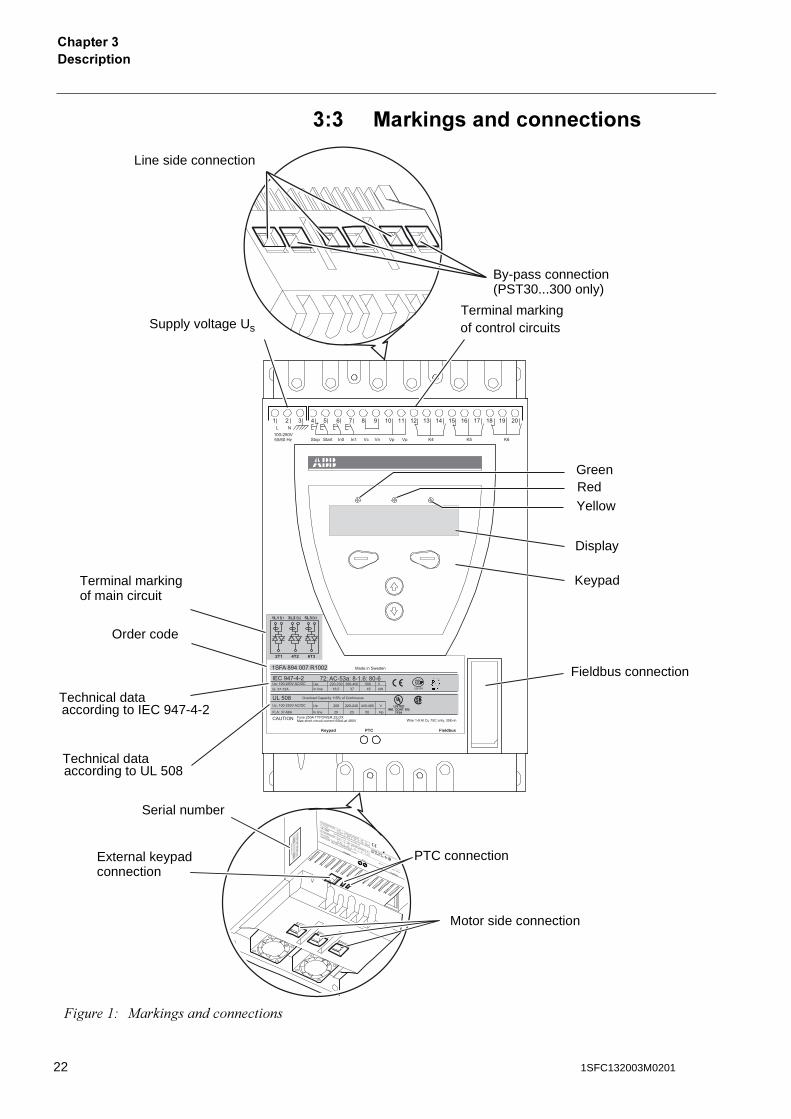
Line side connection
By-pass connection
Serial number
Supply voltage Us
Terminal marking of control circuits
GreenRed Yellow
Display
Keypad
Fieldbus connection
Motor side connection
PTC connectionExternal keypad
Terminal markingof main circuit
Order code
Technical dataaccording to IEC 947-4-2
Technical dataaccording to UL 508
connection
(PST30...300 only)
�����"# ��������������������
22 1SFC132003M0201
-����������
��������
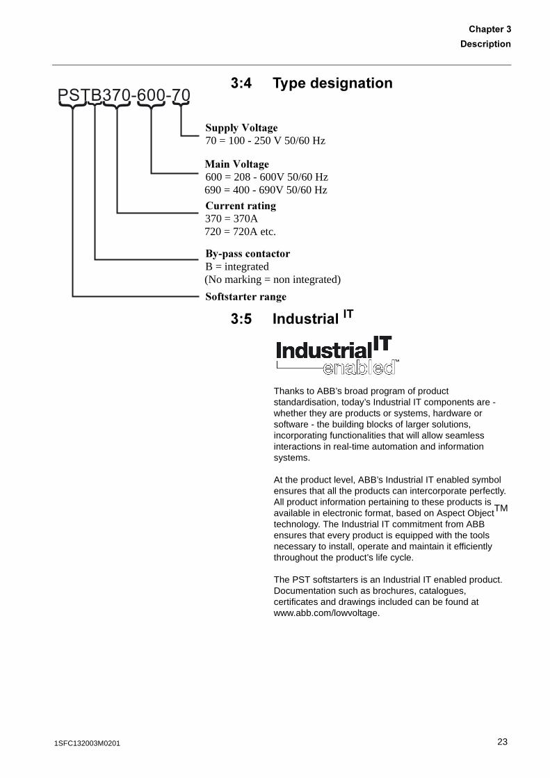
��. ��������������
��! �����������
Thanks to ABB’s broad program of product standardisation, today’s Industrial IT components are - whether they are products or systems, hardware or software - the building blocks of larger solutions, incorporating functionalities that will allow seamless interactions in real-time automation and information systems.
At the product level, ABB’s Industrial IT enabled symbol ensures that all the products can intercorporate perfectly. All product information pertaining to these products is available in electronic format, based on Aspect ObjectTM technology. The Industrial IT commitment from ABB ensures that every product is equipped with the tools necessary to install, operate and maintain it efficiently throughout the product’s life cycle.
The PST softstarters is an Industrial IT enabled product. Documentation such as brochures, catalogues, certificates and drawings included can be found at www.abb.com/lowvoltage.
PSTB370-600-70} } }}}
������������70 = 100 - 250 V 50/60 Hz
��������600 = 208 - 600V 50/60 Hz
690 = 400 - 690V 50/60 Hz
�����������370 = 370A
720 = 720A etc.
�������������B = integrated
(No marking = non integrated)
������������
231SFC132003M0201
-������������������
��0 ?�<�������������������
The product is designed to minimise the environmental affects during manufacturing and use of the product. Most of the materials used, are of recycle type and shall be handled and recycled according to existing laws.
Further information regarding used material and recycling of the product can be found at:www.abb.com/lowvoltage
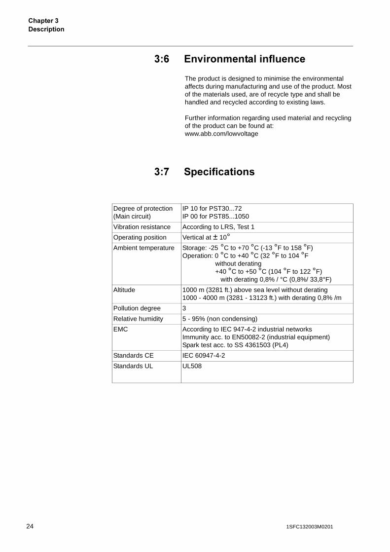
��* ��������������
Degree of protection(Main circuit)
IP 10 for PST30...72IP 00 for PST85...1050
Vibration resistance According to LRS, Test 1
Operating position Vertical at ± 10°Ambient temperature Storage: -25 °C to +70 °C (-13 °F to 158 °F)
Operation: 0 °C to +40 °C (32 °F to 104 °F without derating+40 °C to +50 °C (104 °F to 122 °F)
with derating 0,8% / °C (0,8%/ 33,8°F)
Altitude 1000 m (3281 ft.) above sea level without derating1000 - 4000 m (3281 - 13123 ft.) with derating 0,8% /m
Pollution degree 3
Relative humidity 5 - 95% (non condensing)
EMC According to IEC 947-4-2 industrial networksImmunity acc. to EN50082-2 (industrial equipment)Spark test acc. to SS 4361503 (PL4)
Standards CE IEC 60947-4-2
Standards UL UL508
24 1SFC132003M0201
-����������
��������
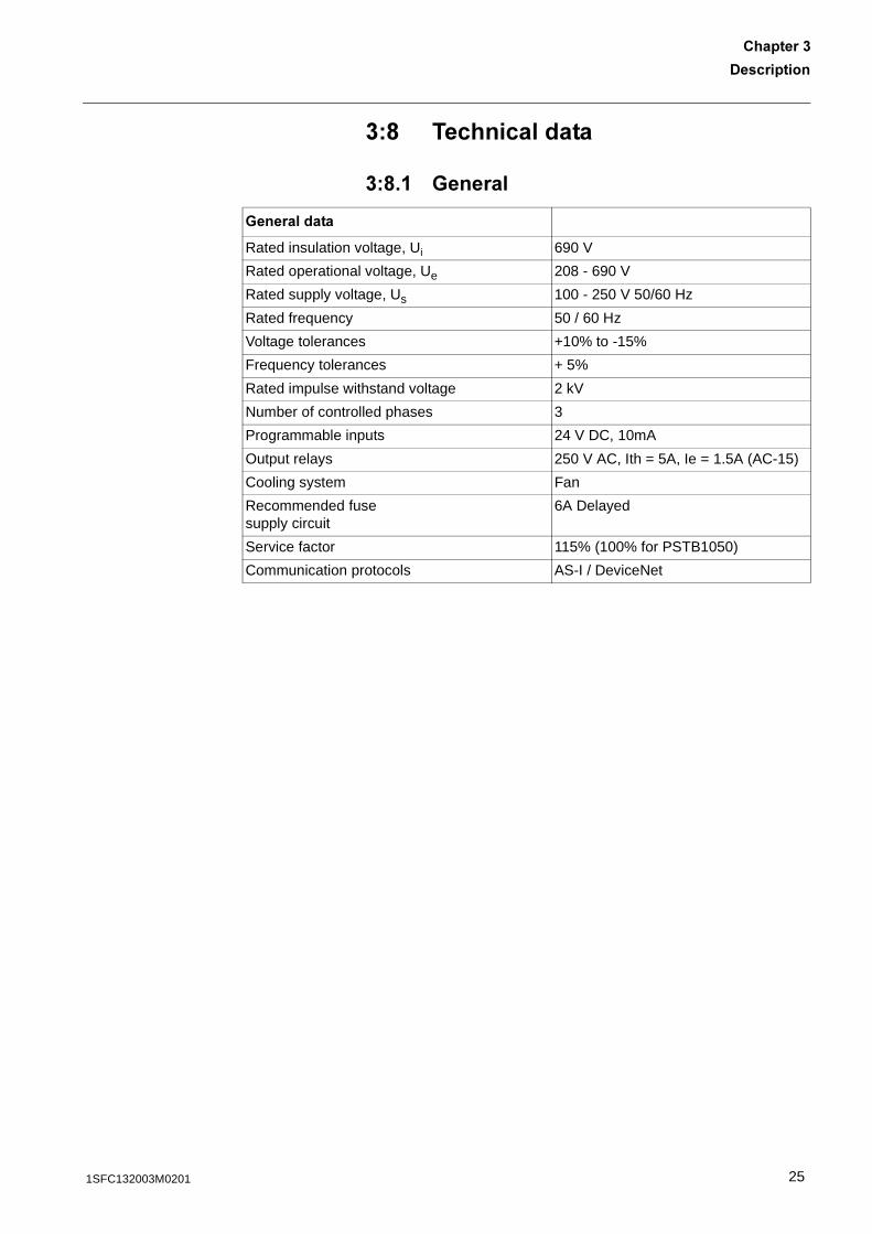
��6 ������������
��6� "������
"����������
Rated insulation voltage, Ui 690 V
Rated operational voltage, Ue 208 - 690 V
Rated supply voltage, Us 100 - 250 V 50/60 Hz
Rated frequency 50 / 60 Hz
Voltage tolerances +10% to -15%
Frequency tolerances + 5%
Rated impulse withstand voltage 2 kV
Number of controlled phases 3
Programmable inputs 24 V DC, 10mA
Output relays 250 V AC, Ith = 5A, Ie = 1.5A (AC-15)
Cooling system Fan
Recommended fuse supply circuit
6A Delayed
Service factor 115% (100% for PSTB1050)
Communication protocols AS-I / DeviceNet
251SFC132003M0201
-������������������
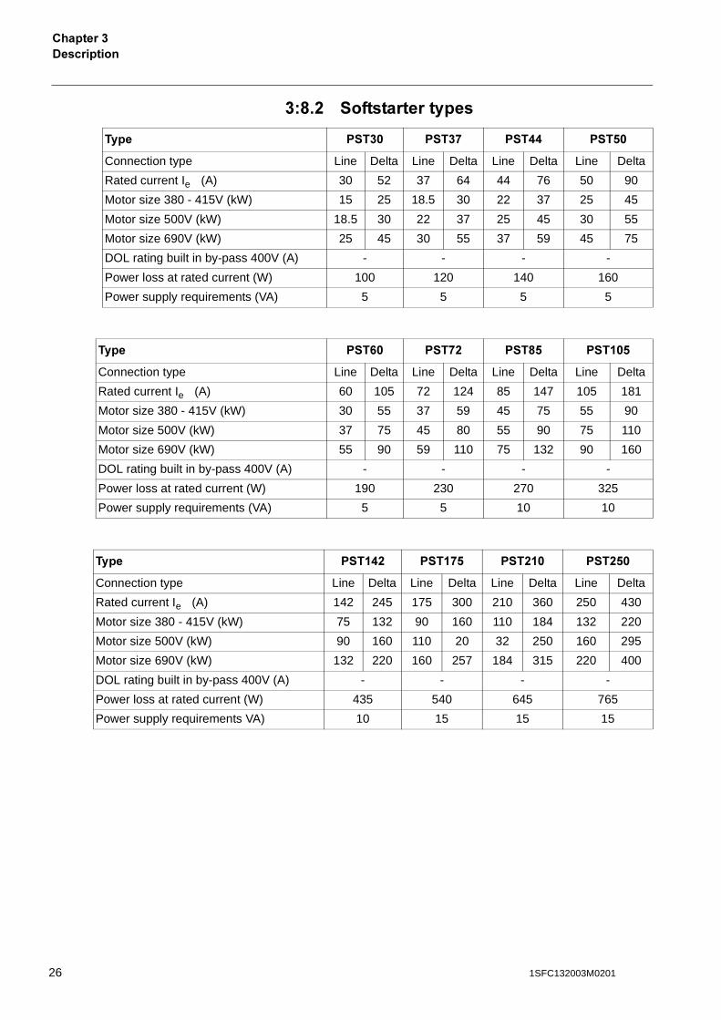
��6�% ����������������
��� ��� ��* �.. �!�
Connection type Line Delta Line Delta Line Delta Line Delta
Rated current Ie (A) 30 52 37 64 44 76 50 90
Motor size 380 - 415V (kW) 15 25 18.5 30 22 37 25 45
Motor size 500V (kW) 18.5 30 22 37 25 45 30 55
Motor size 690V (kW) 25 45 30 55 37 59 45 75
DOL rating built in by-pass 400V (A) - - - -
Power loss at rated current (W) 100 120 140 160
Power supply requirements (VA) 5 5 5 5
��� �0� �*% �6! � �!
Connection type Line Delta Line Delta Line Delta Line Delta
Rated current Ie (A) 60 105 72 124 85 147 105 181
Motor size 380 - 415V (kW) 30 55 37 59 45 75 55 90
Motor size 500V (kW) 37 75 45 80 55 90 75 110
Motor size 690V (kW) 55 90 59 110 75 132 90 160
DOL rating built in by-pass 400V (A) - - - -
Power loss at rated current (W) 190 230 270 325
Power supply requirements (VA) 5 5 10 10
��� � .% � *! �% � �%!�
Connection type Line Delta Line Delta Line Delta Line Delta
Rated current Ie (A) 142 245 175 300 210 360 250 430
Motor size 380 - 415V (kW) 75 132 90 160 110 184 132 220
Motor size 500V (kW) 90 160 110 20 32 250 160 295
Motor size 690V (kW) 132 220 160 257 184 315 220 400
DOL rating built in by-pass 400V (A) - - - -
Power loss at rated current (W) 435 540 645 765
Power supply requirements VA) 10 15 15 15
26 1SFC132003M0201
-����������
��������
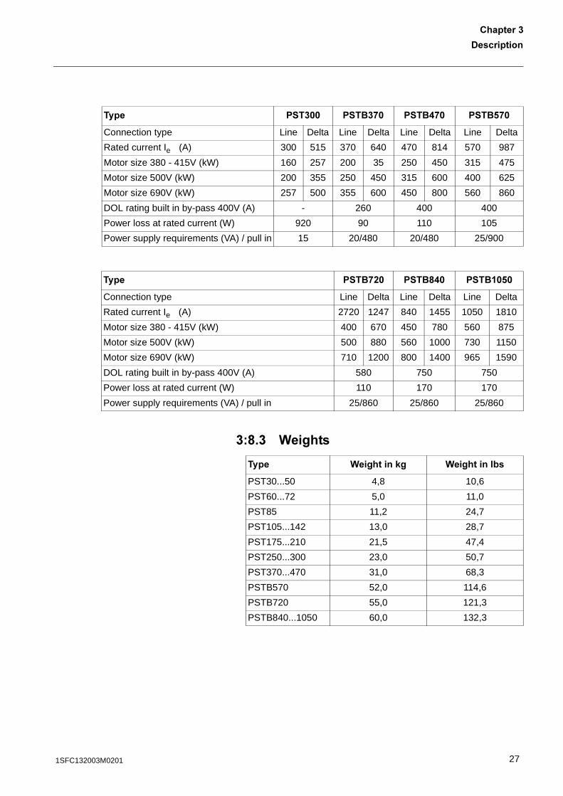
��6�� (������
��� ���� ���*� ��.*� ��!*�
Connection type Line Delta Line Delta Line Delta Line Delta
Rated current Ie (A) 300 515 370 640 470 814 570 987
Motor size 380 - 415V (kW) 160 257 200 35 250 450 315 475
Motor size 500V (kW) 200 355 250 450 315 600 400 625
Motor size 690V (kW) 257 500 355 600 450 800 560 860
DOL rating built in by-pass 400V (A) - 260 400 400
Power loss at rated current (W) 920 90 110 105
Power supply requirements (VA) / pull in 15 20/480 20/480 25/900
��� ��*%� ��6.� �� �!�
Connection type Line Delta Line Delta Line Delta
Rated current Ie (A) 2720 1247 840 1455 1050 1810
Motor size 380 - 415V (kW) 400 670 450 780 560 875
Motor size 500V (kW) 500 880 560 1000 730 1150
Motor size 690V (kW) 710 1200 800 1400 965 1590
DOL rating built in by-pass 400V (A) 580 750 750
Power loss at rated current (W) 110 170 170
Power supply requirements (VA) / pull in 25/860 25/860 25/860
��� (�������,� (����������
PST30...50 4,8 10,6
PST60...72 5,0 11,0
PST85 11,2 24,7
PST105...142 13,0 28,7
PST175...210 21,5 47,4
PST250...300 23,0 50,7
PST370...470 31,0 68,3
PSTB570 52,0 114,6
PSTB720 55,0 121,3
PSTB840...1050 60,0 132,3
271SFC132003M0201
-������������������
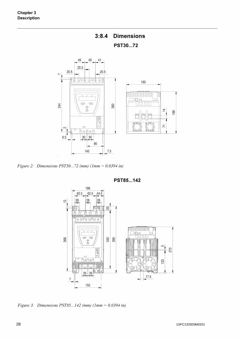
��6�. -���������
������*%
�6!��� .%
�����$# ��������%��&1���,$8��98"��:1!1&.(�9
�����&# ��������%��-*���"($8��98"��:1!1&.(�9
28 1SFC132003M0201
-����������
��������
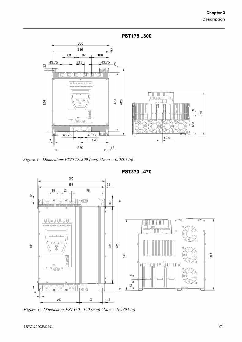
� *!������
��*����.*�
12
7
�����(# ��������%��",*��&118��98"��:1!1&.(�9
�����*# ��������%��&,1���(,18��98"��:1!1&.(�9
291SFC132003M0201
-������������������
��!*���� �!�
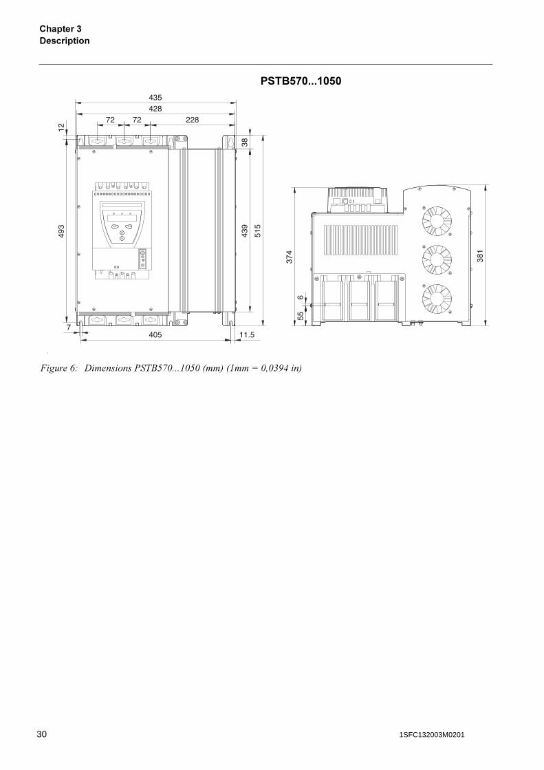
�����+# ��������%��4*,1���"1*18��98"��:1!1&.(�9
30 1SFC132003M0201

/�������
�������./�������
Receiving, unpacking and checking .................................................................. 33
Intermediate storage..................................................................................... 33
Mounting............................................................................................................ 33
Handling when mounting .............................................................................. 33Requirements ............................................................................................... 34Minimum distance to wall/front ..................................................................... 34Minimum enclosure sizes ............................................................................. 35
311SFC132003M0201

32 1SFC132003M0201
/�������
�������.
�������./�������
This chapter describes instructions on how to receive the softstarter and how to mount it in a proper way.
.� :����<���'�����,����������,���
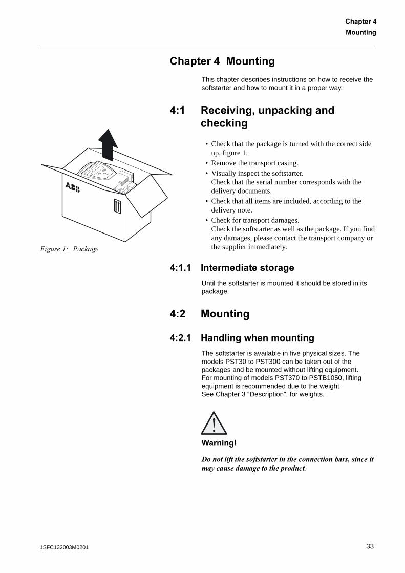
• Check that the package is turned with the correct side up, figure 1.
• Remove the transport casing.• Visually inspect the softstarter.
Check that the serial number corresponds with the delivery documents.
• Check that all items are included, according to the delivery note.
• Check for transport damages.Check the softstarter as well as the package. If you find any damages, please contact the transport company or the supplier immediately.
.� � �������������������
Until the softstarter is mounted it should be stored in its package.
.�% /�������
.�%� 1�������=�����������
The softstarter is available in five physical sizes. The models PST30 to PST300 can be taken out of the packages and be mounted without lifting equipment.For mounting of models PST370 to PSTB1050, lifting equipment is recommended due to the weight.See Chapter 3 “Description”, for weights.
(������)
������������ ������������������ �������������������������������������������� ��������
�����"# %������
331SFC132003M0201
/��������������.
.�%�% :�;���������
See Chapter 3 “Description” for environmental requirements.
.�%�� /����������������=���������
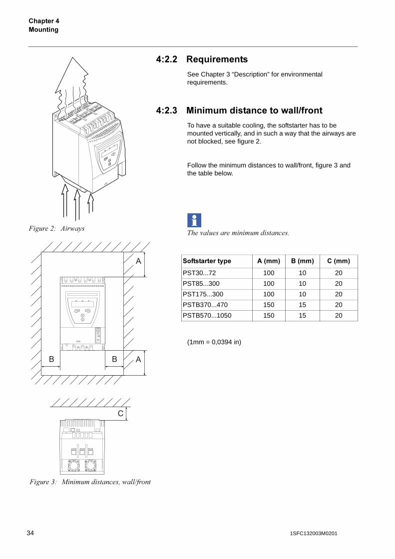
To have a suitable cooling, the softstarter has to be mounted vertically, and in such a way that the airways are not blocked, see figure 2.
Follow the minimum distances to wall/front, figure 3 and the table below.
���'� ��������������������
(1mm = 0,0394 in)
��������������� #3��4 �3��4 �3��4
PST30...72 100 10 20
PST85...300 100 10 20
PST175...300 100 10 20
PSTB370...470 150 15 20
PSTB570...1050 150 15 20
�����$# )� �5�
A
B B
C
A
�����&# �������������! � 7�����
34 1SFC132003M0201
/�������
�������.
.�%�. /�����������������@��
In applications where the softsarter is installed in an enclosure, the following minimum enclosure sizes and fan capacities are recommended.
(1mm = 0,0394 in)
-������������������������
See Chapter 3 “Description” .
/�������������������������
��������������� ( 1 - 7����������
PST30...72 300 400 250 42 m3/h
PST85...142 400 500 300 95 m3/h
PST175...300 500 600 300 210 m3/h
PSTB370...470 600 600 400 210 m3/h
PSTB570...1050 750 900 400 210 m3/h
351SFC132003M0201

/��������������.
36 1SFC132003M0201
����������
�������!����������
General .............................................................................................................. 39
Electrical connection.......................................................................................... 40
Main circuit ................................................................................................... 40External By-Pass contactor ..................................................................... 41
Supply voltage and control circuit................................................................. 42Supply voltage, terminals 1 and 2 ........................................................... 42Earthing, terminal 3 ................................................................................. 42Start and Stop, terminals 4, 5, 8, 9, 10, 11 .............................................. 43Programmable inputs, terminals 6 and 7................................................. 45Programmable output relay K4, terminals 12, 13 and 14 ........................ 46Programmable output relay K5, terminals 15, 16 and 17 ........................ 46Programmable output relay K6 terminals 18, 19 and 20 ......................... 47PTC input ................................................................................................ 47
Connection of communication devices (optional) .............................................. 48
Fieldbus communication............................................................................... 48
371SFC132003M0201

38 1SFC132003M0201
����������
�������!
�������!����������
This chapter describes the electrical connections as well as connections for communication devices that have to be made before you can use the softstarter.
!� "������
�������)
#��������������������������������������������������������������������������������� ��������������������������������������������
For quickly minimised connection, see Chapter 2 “Quickstart”
391SFC132003M0201
�����������������!
!�% ?�������������������
!�%� /����������
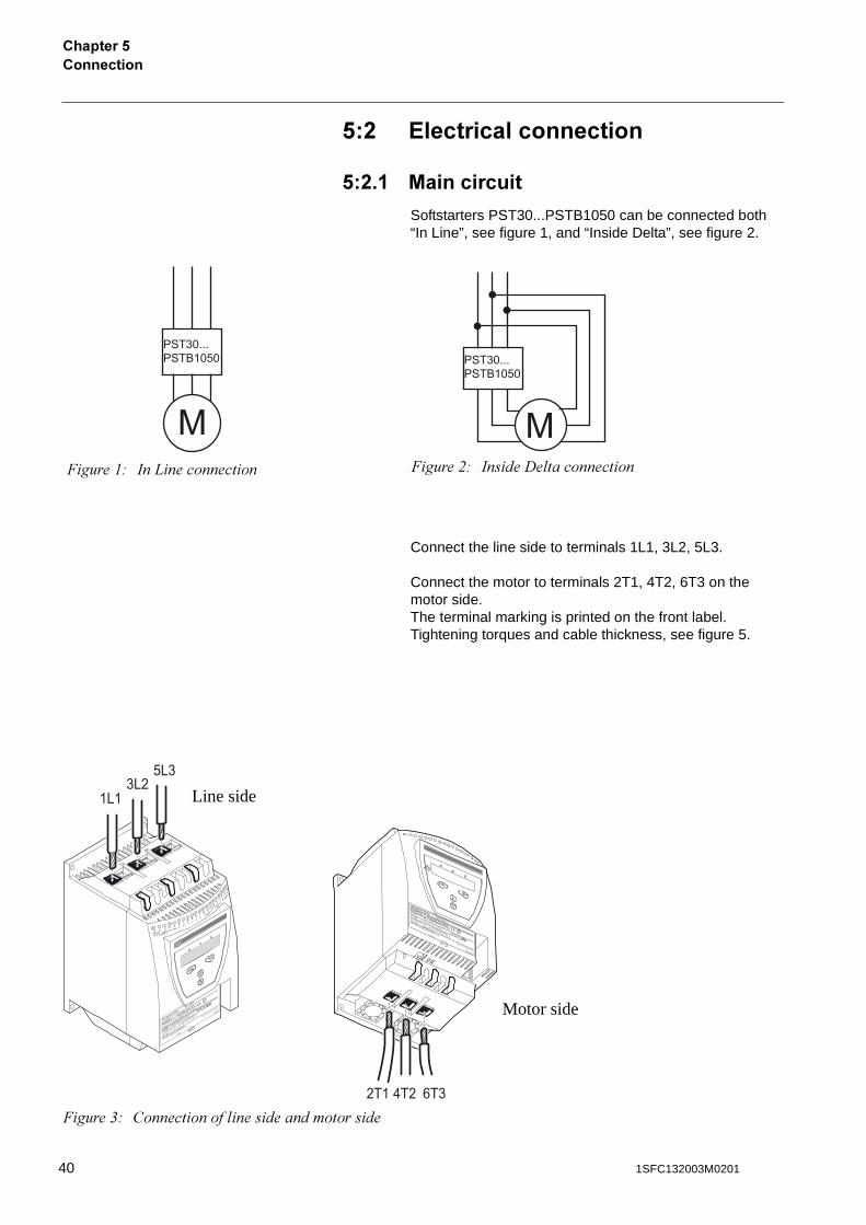
Softstarters PST30...PSTB1050 can be connected both “In Line”, see figure 1, and “Inside Delta”, see figure 2.
Connect the line side to terminals 1L1, 3L2, 5L3.
Connect the motor to terminals 2T1, 4T2, 6T3 on the motor side. The terminal marking is printed on the front label.Tightening torques and cable thickness, see figure 5.
�����"# ��0����������� �����$# ������� �����������
1L13L2
5L3
1 100-250V Stop Start In0 In1 Vc
50/60 Hz
2 3 4 5 6 7 8 9 10 Vp
Vp 11 K4 12 13 14
Vn
15 16
K5
1718
19
K6
20
LISTED 7F39
IND. CONT. EQ.
1SFA 894 007 R1002
IEC 947-4-2
Ie: 37-72AUs: 100-250V AC/DC
UL 508
Uc: 100-250V AC/DC
FLA: 37-68A
Made in Sweden
Ue:
220-230 380-400 500
V
72: AC-53a: 8-1.6: 80-6
In line 1
8,5 3
7
45 k
W
Ue
208
220-240 440-480 V
PTC
Key-Pad
FELDBUSS
CAUTIONFuse 250A TYPOWER ZILOX
Max short circuit current 65kA at 480V
Wire 1-8 Al Cu 75C only, 35lb-in
Overload Capacity 115% of Continuous
LISTED 7F39IND. CONT. EQ.
1SFA 894 007 R1002
IEC 947-4-2Ie: 37-72A
Us: 100-250V AC/DCUL 508Uc: 100-250V AC/DC
FLA: 37-68A
Made in Sweden
Ue: 220-230 380-400 500 V
72: AC-53a: 8-1.6: 80-6
In line 18,5 37 45 kW
Ue 208 220-240 440-480 V
In line 20 20 50 Hp
CAUTION Fuse 250A TYPOWER ZILOX
Max short circuit current 65kA at 480V
Wire 1-8 Al Cu 75C only, 35lb-in
Overload Capacity 115% of Continuous
PTC
Key-Pad
FIELDBUS
2T1 4T2 6T3�����&# ����������� ����������������
Motor side
Line side
40 1SFC132003M0201
����������
�������!
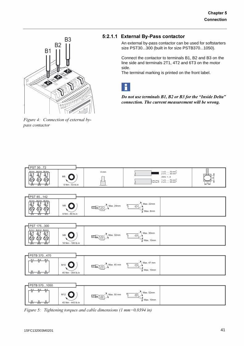
!�%� � ?8��������2 ������������An external by-pass contactor can be used for softstarters size PST30...300 (built in for size PSTB370...1050).
Connect the contactor to terminals B1, B2 and B3 on the line side and terminals 2T1, 4T2 and 6T3 on the motor side.The terminal marking is printed on the front label.
��������������������$%��$&����$'������ ��()����� ����*�����������+ �����������������������������������
1 100-250V
Stop Start In0 In1 Vc
50/60 Hz
2 3 4 5 6 7 8 9 10 Vp
Vp 11 K4 12 13 14
Vn
15 16
K5
1718
19
K6
20
B1 B2
B3
�����(# ������������3����� �5��������������
A
�����*# �����������;��������� ���������8"��:1!1&.(�9
411SFC132003M0201
�����������������!
!�%�% ������<�����������������������
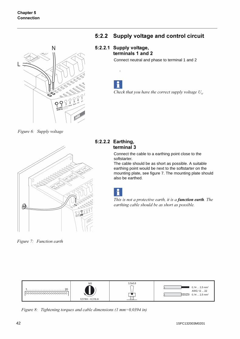
!�%�%� ������<������'��������� ���%Connect neutral and phase to terminal 1 and 2
.
���������5����'��������������� 5'� ����<��
!�%�%�% ?�������'���������Connect the cable to a earthing point close to the softstarter.The cable should be as short as possible. A suitable earthing point would be next to the softstarter on the mounting plate, see figure 7. The mounting plate should also be earthed.
���������������'������!��������������� �������������� ����� ����������������� ��
1 100-250V
Stop Start In0 In1 V
50/60 Hz
2 3 4 5 6 7
L
N
�����+# ���� 5'� ����
1 100-250V Stop Start In0 In1
50/60 Hz
2 3 4 5 6 7
�����,# ������������
�����-# �����������;��������� ���������8"��:1!1&.(�9
42 1SFC132003M0201
����������
�������!
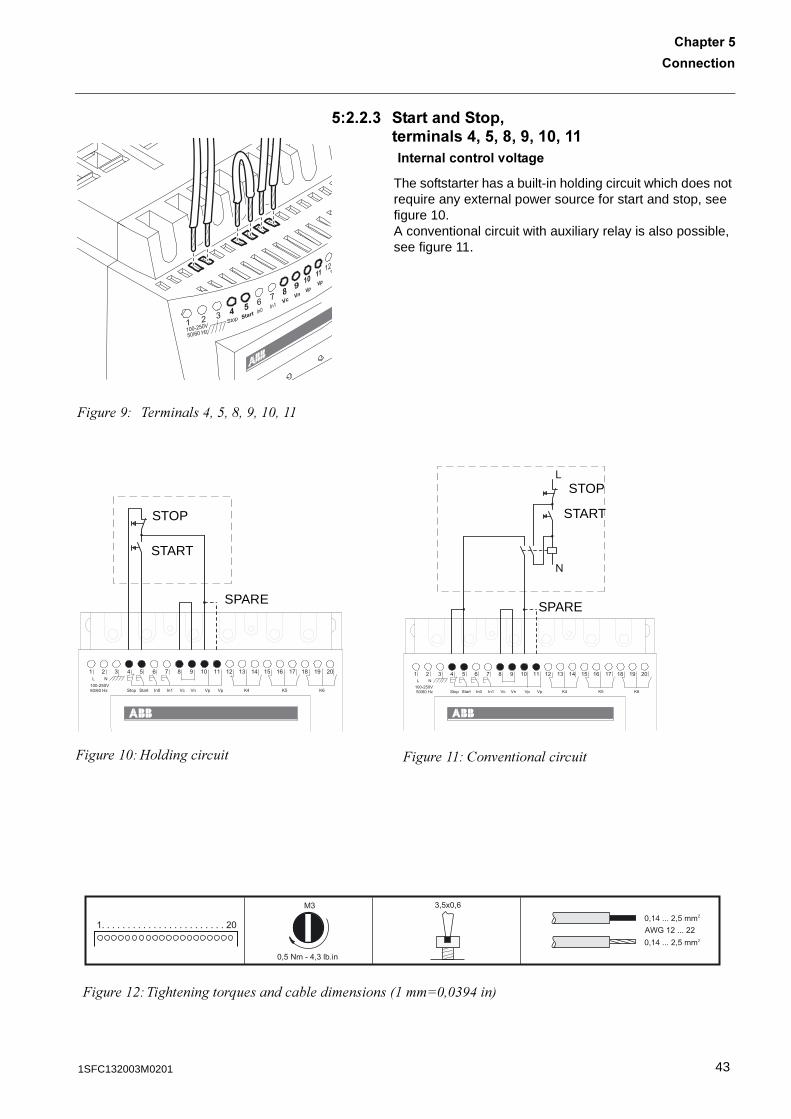
!�%�%�� ������������'���������.'!'6'5' �' ���������������<������
The softstarter has a built-in holding circuit which does not require any external power source for start and stop, see figure 10.A conventional circuit with auxiliary relay is also possible, see figure 11.
1 100-250V Stop Start In0 In1 Vc
50/60 Hz
2 3 4 5 6 7 8 9 10 Vp
Vp 11 12
Vn
�����.# ������ �(!*!-!.!"1!""
1 2 3 4 5 6 7 8 9 10 11 12 13 14 15 16 17 18 19 20
100-250VL N
Stop Start In1 Vc Vn Vp Vp K4 In050/60 Hz K5 K6
�����"1#�� ��������
START
STOP
SPARE
1 2 3 4 5 6 7 8 9 10 11 12 13 14 15 16 17 18 19 20
100-250VL N
Stop Start In1 Vc Vn Vp Vp K4 In050/60 Hz K5 K6
L
N
�����""# ���'������ �����
STOP
START
SPARE
�����"$#�����������;��������� ���������8"��:1!1&.(�9
431SFC132003M0201
�����������������!
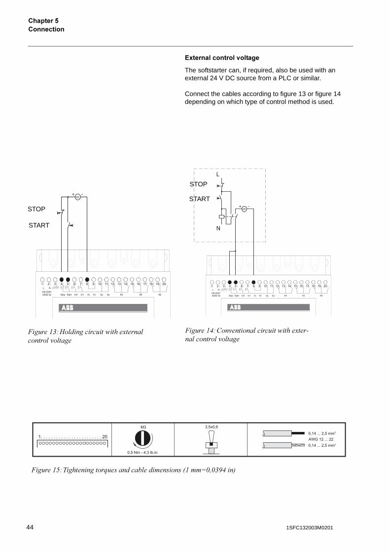
?8�������������<������
The softstarter can, if required, also be used with an external 24 V DC source from a PLC or similar.
Connect the cables according to figure 13 or figure 14 depending on which type of control method is used.
1 2 3 4 5 6 7 8 9 10 11 12 13 14 15 16 17 18 19 20
100-250VL N
Stop Start In1 Vc Vn Vp Vp K4 In050/60 Hz K5 K6
DC+ -
STOP
START
�����"&#�� �������� ���3����� ������ '� ����
1 2 3 4 5 6 7 8 9 10 11 12 13 14 15 16 17 18 19 20
100-250VL N
Stop Start In1 Vc Vn Vp Vp K4 In050/60 Hz K5 K6
DC+ -
L
N
STOP
START
�����"(#���'������ ����� ���3������ ������ '� ����
�����"*#�����������;��������� ���������8"��:1!1&.(�9
44 1SFC132003M0201
����������
�������!
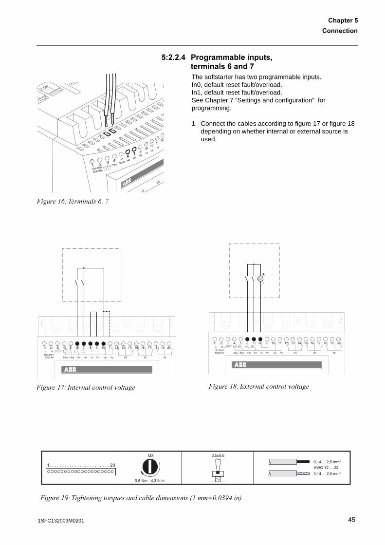
!�%�%�. �����������������'���������0���*The softstarter has two programmable inputs.In0, default reset fault/overload.In1, default reset fault/overload.See Chapter 7 “Settings and configuration” for programming.
1 Connect the cables according to figure 17 or figure 18 depending on whether internal or external source is used.
1 100-250V Stop Start In0 In1 Vc
50/60Hz
2 3 4 5 6 7 8 9 10 Vp
Vp 11 12
Vn
�����"+#������ �+!,
1 2 3 4 5 6 7 8 9 10 11 12 13 14 15 16 17 18 19 20
100-250VL N
Stop Start In1 Vc Vn Vp Vp K4 In050/60 Hz K5 K6
�����",# ������� ������ '� ����
DC+
-
1 2 3 4 5 6 7 8 9 10 11 12 13 14 15 16 17 18 19 20
100-250VL N
Stop Start In1 Vc Vn Vp Vp K4 In050/60 Hz K5 K6
�����"-#23����� ������ '� ����
�����".#�����������;��������� ���������8"��:1!1&.(�9
451SFC132003M0201
�����������������!
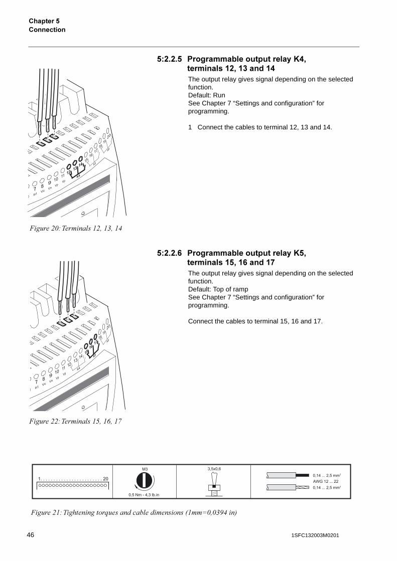
!�%�%�! ����������������������A.'��������� %' ���� .The output relay gives signal depending on the selected function.Default: RunSee Chapter 7 “Settings and configuration” for programming.
1 Connect the cables to terminal 12, 13 and 14.
!�%�%�0 ����������������������A!'��������� !' 0��� *The output relay gives signal depending on the selected function.Default: Top of rampSee Chapter 7 “Settings and configuration” for programming.
Connect the cables to terminal 15, 16 and 17.
�����$1#������ �"$!"&!"(
�����$"#�����������;��������� ���������8"��:1!1&.(�9
�����$$#������ �"*!"+!",
46 1SFC132003M0201
����������
�������!
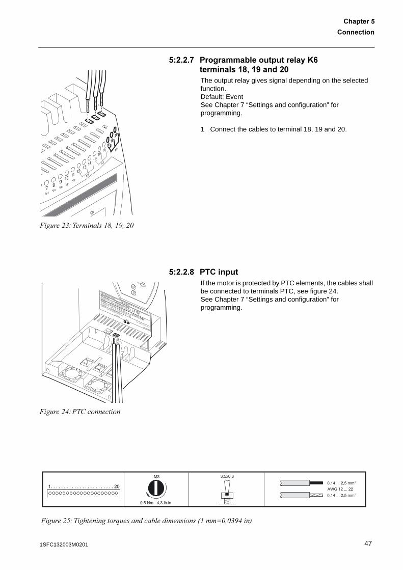
!�%�%�* ����������������������A0��������� 6' 5���%�The output relay gives signal depending on the selected function.Default: EventSee Chapter 7 “Settings and configuration” for programming.
1 Connect the cables to terminal 18, 19 and 20.
!�%�%�6 ������If the motor is protected by PTC elements, the cables shall be connected to terminals PTC, see figure 24.See Chapter 7 “Settings and configuration” for programming.
�����$&#������ �"-!".!$1
LISTED 7F39IND. CONT. EQ.
1SFA 894 007 R1002
IEC 947-4-2Ie: 37-72A
Us: 100-250V AC/DCUL 508Uc: 100-250V AC/DC
FLA: 37-68A
Made in Sweden
Ue: 220-230 380-400 500 V
72: AC-53a: 8-1.6: 80-6
In line 18,5 37 45 kW
Ue 208 220-240 440-480 V
In line 20 20 50 Hp
CAUTION Fuse 250A TYPOWER ZILOX
Max short circuit current 65kA at 480V
Wire 1-8 Al Cu 75C only, 35lb-in
Overload Capacity 115% of Continuous
PTC
Key-Pad
FELDBUSS
�����$(#%�����������
�����$*#�����������;��������� ���������8"��:1!1&.(�9
471SFC132003M0201
�����������������!
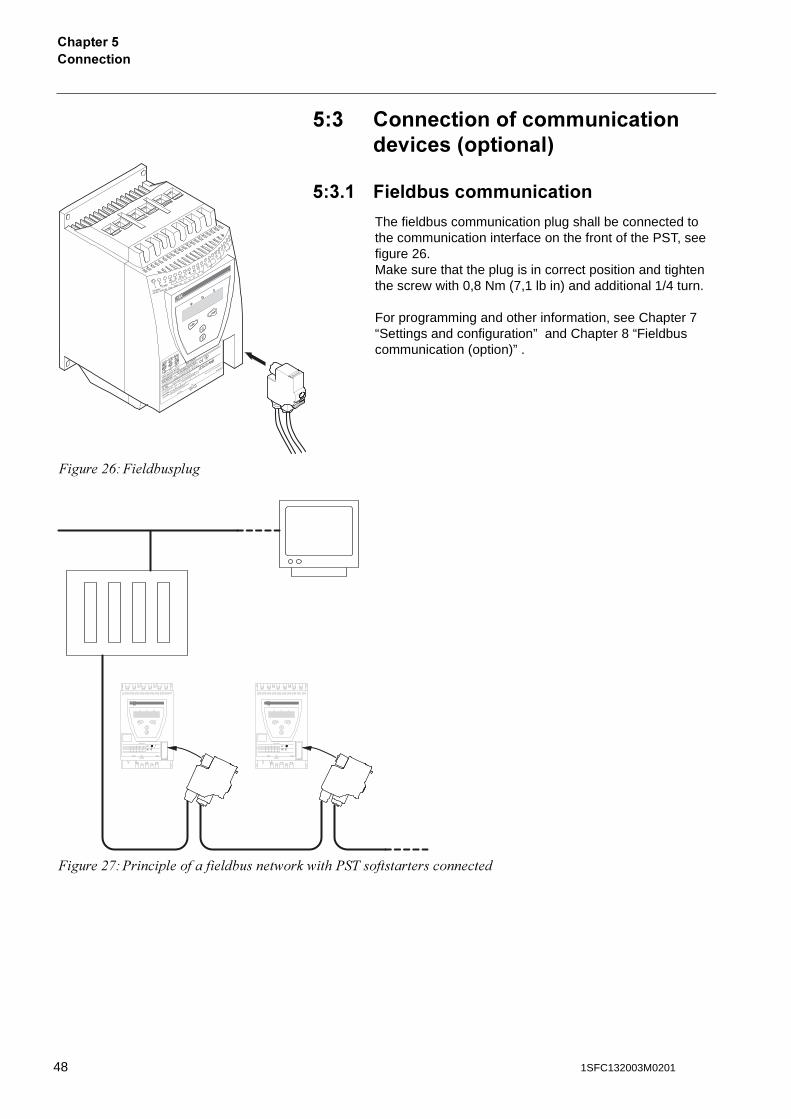
!�� ���������������������������<����3��������4
!��� 7��������������������
The fieldbus communication plug shall be connected to the communication interface on the front of the PST, see figure 26. Make sure that the plug is in correct position and tighten the screw with 0,8 Nm (7,1 lb in) and additional 1/4 turn.
For programming and other information, see Chapter 7 “Settings and configuration” and Chapter 8 “Fieldbus communication (option)” .
�����$+#�� ����� ��
�����$,#%���� ������ ������� ��� ��%�����������������������
48 1SFC132003M0201
1����2/���������������31/�4
�������01����2/���������������31/�4
Overview............................................................................................................ 51
Application .................................................................................................... 51Design .......................................................................................................... 52Password...................................................................................................... 54
Setting password..................................................................................... 54Wrong password ..................................................................................... 54
Locking/unlocking the keypad ...................................................................... 55
Menu tree .......................................................................................................... 56
Overview....................................................................................................... 56Top level ....................................................................................................... 57Settings menu............................................................................................... 57Local Control menu ...................................................................................... 58
Start/Stop the motor ................................................................................ 59Jog........................................................................................................... 59DOL start ................................................................................................. 59
Event Log menu ........................................................................................... 60Status Information menu .............................................................................. 60Reset Events menu ...................................................................................... 60
491SFC132003M0201

50 1SFC132003M0201

1����2/���������������31/�4
�������0
�������01����2/���������������31/�4
This chapter describes how the human-machine interface (keypad and display) works.
0� ><��<��=
0� � #����������
The Human-Machine Interface is used for several purposes such as programming the softstarter, i.e setup of inputs and outputs, protection functions, warning levels, fieldbus communication etc. The HMI is also used for monitoring, local control and status information of the softstarter.
511SFC132003M0201
1����2/���������������31/�4�������0
0� �% -�����
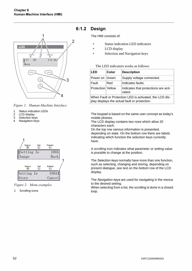
The HMI consists of:
• Status indication LED indicators• LCD display• Selection and Navigation keys
The LED indicators works as follows:
The keypad is based on the same user concept as today’s mobile phones.The LCD display contains two rows which allow 20 characters each.On the top row various information is presented, depending on state. On the bottom row there are labels indicating which function the selection keys currently have.
A scrolling icon indicates what parameter or setting value is possible to change at the position.
The �� ��������� normally have more than one function, such as selecting, changing and storing, depending on present dialogue, see text on the bottom row of the LCD display.
The ������������ are used for navigating in the menus to the desired setting.When selecting from a list, the scrolling is done in a closed loop.
Power on ProtectionFault
1
2
3
4
�����"# ���������������������
1 Status indication LEDs2 LCD display3 Selection keys4 Navigation keys
�� �� ������
��
B?- ����� -����������
Power on Green Supply voltage connected.
Fault Red Indicates faults.
Protection Yellow Indicates that protections are acti-vated.
When Fault or Protection LED is activated, the LCD dis-play displays the actual fault or protection.
Power on ProtectionFault
Power on ProtectionFault
1
1
�����$# �����3��� ��
1 Scrolling icons
�������� #����+��� ����
�������� #������� �����
52 1SFC132003M0201
1����2/���������������31/�4
�������0
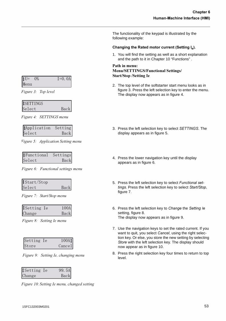
The functionality of the keypad is illustrated by the following example:
�����������:����������������3���������4�
1. You will find the setting as well as a short explanation and the path to it in Chapter 10 “Functions” .
������������ ���������� ��!�������������������������������
2. The top level of the softstarter start menu looks as in figure 3. Press the left selection key to enter the menu. The display now appears as in figure 4.
3. Press the left selection key to select ���� �!�. The display appears as in figure 5.
4. Press the lower navigation key until the display appears as in figure 6.
5. Press the left selection key to select "������ ���#���. Press the left selection key to select �������, figure 7.
6. Press the left selection key to $����� the ����� � setting, figure 8. The display now appears as in figure 9.
7. Use the navigation keys to set the rated current. If you want to quit, you select $���� , using the right selec-tion key. Or else, you store the new setting by selecting ���� with the left selection key. The display should now appear as in figure 10.
8. Press the right selection key four times to return to top level.
�� ��� ��������
�����&# ��� �'�
�$**��,����� ����
�����(# �2���=>�����
� ��������� ���������� ����
�����*# )�� ���������������
-��������� ������"���� ����
�����+# �������� �����������
�����.��� ���� ����
�����,# �����7��������
�������� #����+��� ����
�����-# ������������
�������� #������� �����
�����.# ��������!�����������
�������� ���/��+��� ����
�����"1#������������!�������������
531SFC132003M0201
1����2/���������������31/�4�������0
0� �� ���=���
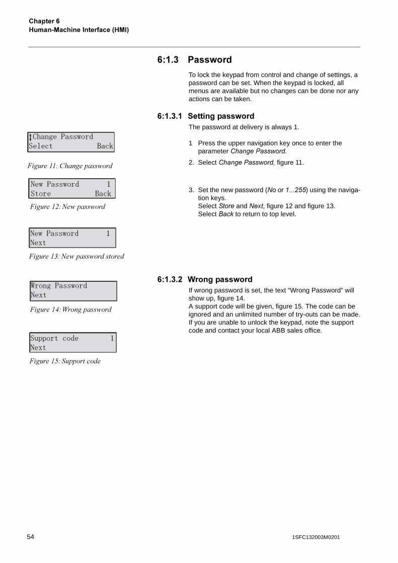
To lock the keypad from control and change of settings, a password can be set. When the keypad is locked, all menus are available but no changes can be done nor any actions can be taken.
0� ��� �����������=���The password at delivery is always 1.
1 Press the upper navigation key once to enter the parameter $����������%���.
2. Select$����������%���&�figure 11.
3. Set the new password (�� or '���())) using the naviga-tion keys.Select����� and ���, figure 12 and figure 13.Select �����to return to top level.
0� ���% (��������=���If wrong password is set, the text “Wrong Password”will show up, figure 14. A support code will be given, figure 15. The code can be ignored and an unlimited number of try-outs can be made.If you are unable to unlock the keypad, note the support code and contact your local ABB sales office.
�+������""0��'���� ����
�����""# ���������� ���
�0���""0��' #���� ����
�����"$#=� ���� ���
�0���""0��' #���
�����"&#=� ���� ���������
1�������""0��'���
�����"(#?�������� ���
�� ������' #���
�����"*#�����������
54 1SFC132003M0201
1����2/���������������31/�4
�������0
0� �. B��,���������,������,�����
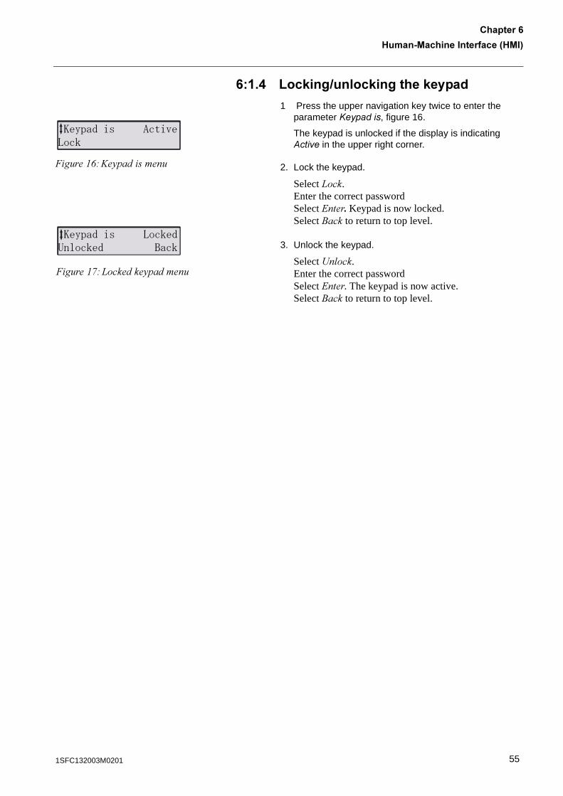
1 Press the upper navigation key twice to enter the parameter *�������, figure 16.
The keypad is unlocked if the display is indicating +��� in the upper right corner.
2. Lock the keypad.
Select0���.Enter the correct passwordSelect2����"�Keypad is now locked.Select 4��� to return to top level.
3. Unlock the keypad.
Select<� ���. Enter the correct passwordSelect 2����. The�keypad is now active.Select 4��� to return to top level.
2% �'��" ����3!���
�����"+#@�5��������
2% �'��" !���'������' ����
�����",#0�������5�������
551SFC132003M0201
1����2/���������������31/�4�������0
0�% /�������
0�%� ><��<��=
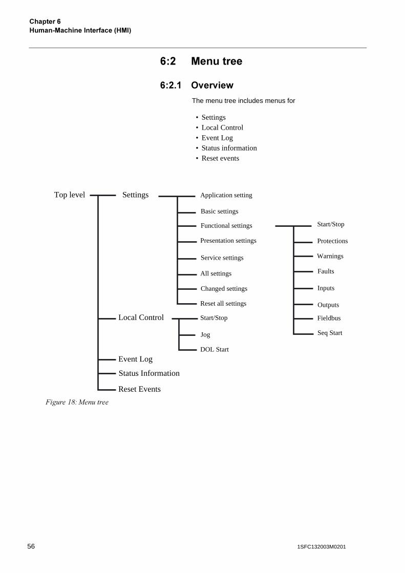
The menu tree includes menus for
• Settings• Local Control• Event Log• Status information• Reset events
�����"-#��������
Application setting
Basic settings
Functional settings
Presentation settings
Service settings
All settings
Changed settings
Reset all settings
Top level Settings
Local Control
Event Log
Status Information
Reset Events
Start/Stop
Jog
DOL Start
Start/Stop
Protections
Warnings
Faults
Inputs
Outputs
Fieldbus
Seq Start
56 1SFC132003M0201
1����2/���������������31/�4
�������0
0�%�% ����<��
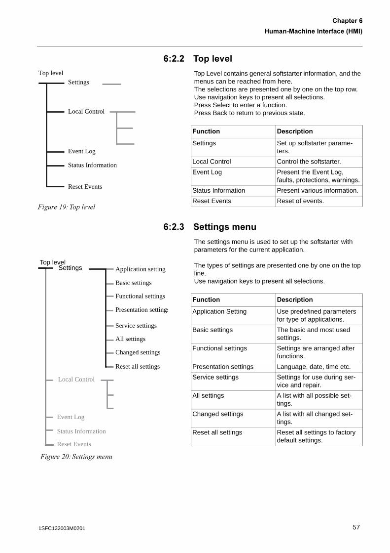
Top Level contains general softstarter information, and the menus can be reached from here.The selections are presented one by one on the top row. Use navigation keys to present all selections. Press Select to enter a function. Press Back to return to previous state.
0�%�� ������������
The settings menu is used to set up the softstarter with parameters for the current application.
The types of settings are presented one by one on the top line.Use navigation keys to present all selections.
Top level
Local Control
�����".#��� �'�
Settings
Event Log
Status Information
Reset Events
7������� -����������
Settings Set up softstarter parame-ters.
Local Control Control the softstarter.
Event Log Present the Event Log, faults, protections, warnings.
Status Information Present various information.
Reset Events Reset of events.
�����$1#�����������
Top levelSettings
Local Control
Event Log
Status Information
Reset Events
Application setting
Basic settings
Functional settings
Presentation settings
Service settings
All settings
Changed settings
Reset all settings
7������� -����������
Application Setting Use predefined parameters for type of applications.
Basic settings The basic and most used settings.
Functional settings Settings are arranged after functions.
Presentation settings Language, date, time etc.
Service settings Settings for use during ser-vice and repair.
All settings A list with all possible set-tings.
Changed settings A list with all changed set-tings.
Reset all settings Reset all settings to factory default settings.
571SFC132003M0201
1����2/���������������31/�4�������0
0�%�. B���������������
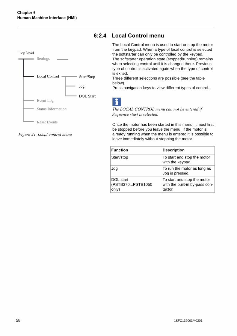
The Local Control menu is used to start or stop the motor from the keypad. When a type of local control is selected the softstarter can only be controlled by the keypad.The softstarter operation state (stopped/running) remains when selecting control until it is changed there. Previous type of control is activated again when the type of control is exited.Three different selections are possible (see the table below).Press navigation keys to view different types of control.
���0/�)0�/=�6/0����������������������;������������� ������
Once the motor has been started in this menu, it must first be stopped before you leave the menu. If the motor is already running when the menu is entered it is possible to leave immediately without stopping the motor.
Top level
Local Control
�����$"#0��� ������ ����
Settings
Event Log
Status Information
Reset Events
Start/Stop
Jog
DOL Start
7������� -����������
Start/stop To start and stop the motor with the keypad.
Jog To run the motor as long as Jog is pressed.
DOL start(PSTB370...PSTB1050 only)
To start and stop the motor with the built-in by-pass con-tactor.
58 1SFC132003M0201
1����2/���������������31/�4
�������0
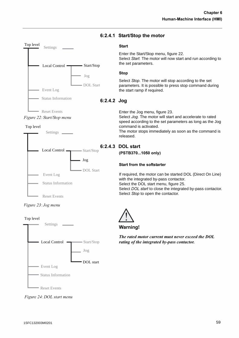
0�%�.� ������������������
�����
Enter the Start/Stop menu, figure 22.Select�����The motor will now start and run according to the set parameters.
����
Select ���. The motor will stop according to the set parameters. It is possible to press stop command during the start ramp if required.
0�%�.�% C��
Enter the Jog menu, figure 23.Select ,��� The motor will start and accelerate to rated speed according to the set parameters as long as the Jog command is activated. The motor stops immediately as soon as the command is released.
0�%�.�� ->B�����3 ���*���� �!�����4
�����������������������
If required, the motor can be started DOL (Direct On Line) with the integrated by-pass contactor.Select the DOL start menu, figure 25. Select -./���� to close the integrated by-pass contactor.Select ��� to open the contactor.
(������)
+ ���������������������������"��������� �� ,-������������ ��������������.�������������
�����$$#�����7��������
Top level
Local Control
Settings
Start/Stop
Jog
DOL StartEvent Log
Status Information
Reset Events
Top level
Local Control
�����$&# A������
Jog
Settings
Event Log
Status Information
Reset Events
Start/Stop
DOL Start
Top level
Local Control
�����$(#�/0���������
DOL start
Settings
Event Log
Status Information
Reset Events
Jog
Start/Stop
591SFC132003M0201
1����2/���������������31/�4�������0
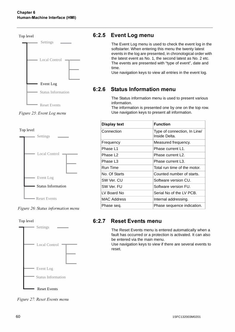
0�%�! ?<���B������
The Event Log menu is used to check the event log in the softstarter. When entering this menu the twenty latest events in the log are presented, in chronological order with the latest event as No. 1, the second latest as No. 2 etc.The events are presented with “type of event”, date and time.Use navigation keys to view all entries in the event log.
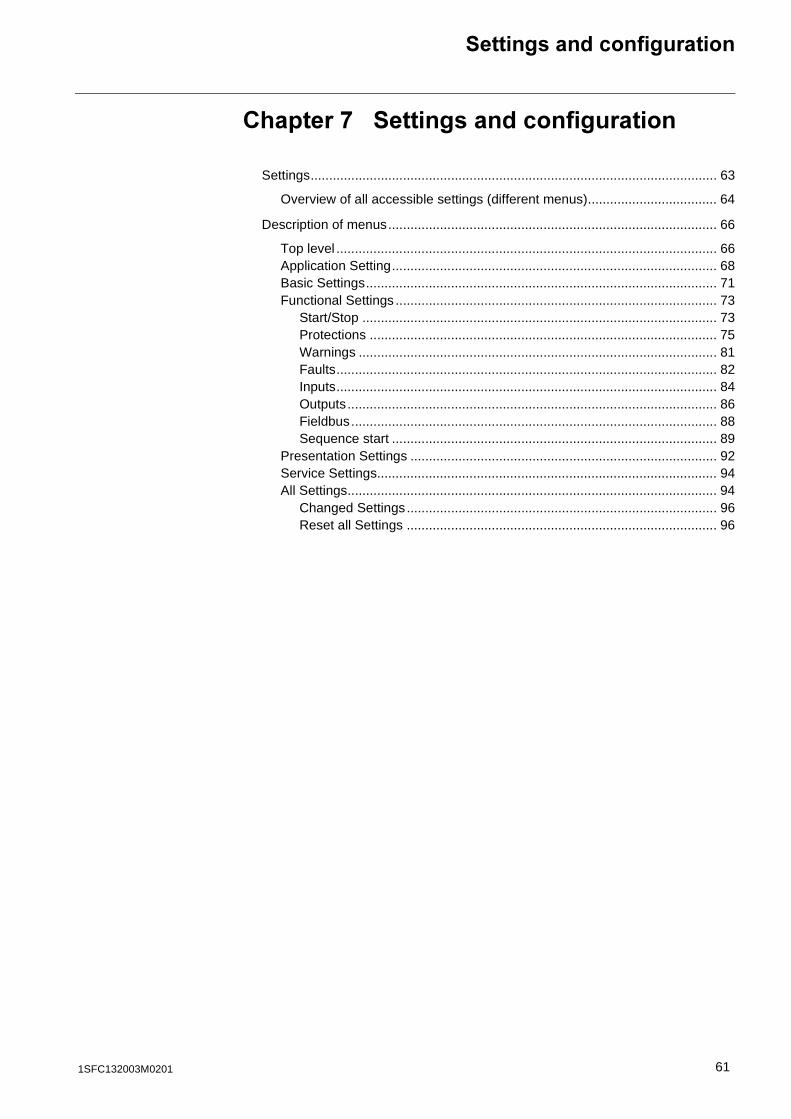
0�%�0 ���������������������
The Status information menu is used to present various information.The information is presented one by one on the top row.Use navigation keys to present all information.
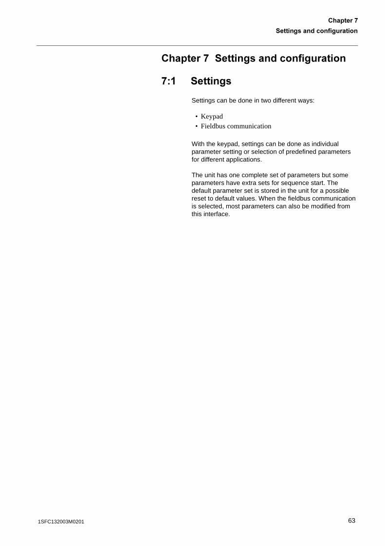
0�%�* :����?<��������
The Reset Events menu is entered automatically when a fault has occurred or a protection is activated. It can also be entered via the main menu.Use navigation keys to view if there are several events to reset.
Top level
�����$*#2'���0������
Settings
Event Log
Status Information
Reset Events
Local Control
Top level
Local Control
Settings
Event Log
Status Information
�����$+#�������������������
Reset Events
-��������8� 7�������
Connection Type of connection, In Line/Inside Delta.
Frequency Measured frequency.
Phase L1 Phase current L1.
Phase L2 Phase current L2.
Phase L3 Phase current L3.
Run Time Total run time of the motor.
No. Of Starts Counted number of starts.
SW Ver. CU Software version CU.
SW Ver. FU Software version FU.
LV Board No Serial No of the LV PCB.
MAC Address Internal addressing.
Phase seq. Phase sequence indication.
Top level
Local Control
Settings
Event Log
Status Information
�����$,#6����2'��������
Reset Events
60 1SFC132003M0201
������������������������
�������*������������������������
Settings.............................................................................................................. 63
Overview of all accessible settings (different menus)................................... 64
Description of menus......................................................................................... 66
Top level ....................................................................................................... 66Application Setting........................................................................................ 68Basic Settings............................................................................................... 71Functional Settings ....................................................................................... 73
Start/Stop ................................................................................................ 73Protections .............................................................................................. 75Warnings ................................................................................................. 81Faults....................................................................................................... 82Inputs....................................................................................................... 84Outputs.................................................................................................... 86Fieldbus................................................................................................... 88Sequence start ........................................................................................ 89
Presentation Settings ................................................................................... 92Service Settings............................................................................................ 94All Settings.................................................................................................... 94
Changed Settings.................................................................................... 96Reset all Settings .................................................................................... 96
611SFC132003M0201

62 1SFC132003M0201
������������������������
�������*
�������*������������������������
*� ��������
Settings can be done in two different ways:
• Keypad• Fieldbus communication
With the keypad, settings can be done as individual parameter setting or selection of predefined parameters for different applications.
The unit has one complete set of parameters but some parameters have extra sets for sequence start. The default parameter set is stored in the unit for a possible reset to default values. When the fieldbus communication is selected, most parameters can also be modified from this interface.
631SFC132003M0201
�������������������������������*
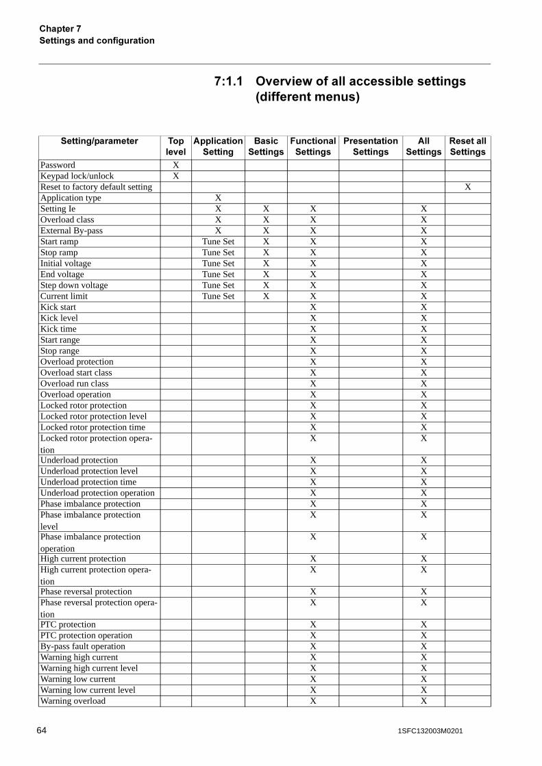
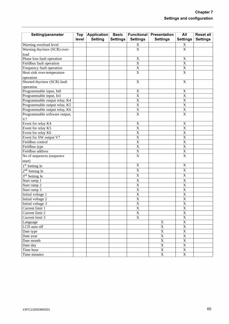
*� � ><��<��=�����������������������3��������������4
����������������� ����<��
#�����������������
�������������
7�����������������
�������������������
#����������
:���������������
Password XKeypad lock/unlock XReset to factory default setting XApplication type XSetting Ie X X X XOverload class X X X XExternal By-pass X X X XStart ramp Tune Set X X XStop ramp Tune Set X X XInitial voltage Tune Set X X XEnd voltage Tune Set X X XStep down voltage Tune Set X X XCurrent limit Tune Set X X XKick start X XKick level X XKick time X XStart range X XStop range X XOverload protection X XOverload start class X XOverload run class X XOverload operation X XLocked rotor protection X XLocked rotor protection level X XLocked rotor protection time X XLocked rotor protection opera-tion
X X
Underload protection X XUnderload protection level X XUnderload protection time X XUnderload protection operation X XPhase imbalance protection X XPhase imbalance protection level
X X
Phase imbalance protection operation
X X
High current protection X XHigh current protection opera-tion
X X
Phase reversal protection X XPhase reversal protection opera-tion
X X
PTC protection X XPTC protection operation X XBy-pass fault operation X XWarning high current X XWarning high current level X XWarning low current X XWarning low current level X XWarning overload X X
64 1SFC132003M0201
������������������������
�������*
Warning overload level X XWarning thyristor (SCR) over-load
X X
Phase loss fault operation X XFieldbus fault operation X XFrequency fault operation X XHeat sink over-temperature operation
X X
Shorted thyristor (SCR) fault operation
X X
Programmable input, In0 X XProgrammable input, In1 X XProgrammable output relay, K4 X XProgrammable output relay, K5 X XProgrammable output relay, K6 X XProgrammable software output, V7
X X
Event for relay K4 X XEvent for relay K5 X XEvent for relay K6 X XEvent for SW output V7 X XFieldbus control X XFieldbus type X XFieldbus address X XNo of sequences (sequence start)
X X
1st Setting Ie X X
2nd Setting Ie X X
3rd Setting Ie X XStart ramp 1 X XStart ramp 2 X XStart ramp 3 X XInitial voltage 1 X XInitial voltage 2 X XInitial voltage 3 X XCurrent limit 1 X XCurrent limit 2 X XCurrent limit 3 X XLanguage X XLCD auto off X XDate type X XDate year X XDate month X XDate day X XTime hour X XTime minutes X X
����������������� ����<��
#�����������������
�������������
7�����������������
�������������������
#����������
:���������������
651SFC132003M0201
�������������������������������*
*�% -�����������������
For detailed description of each function, see Chapter 10 “Functions” .
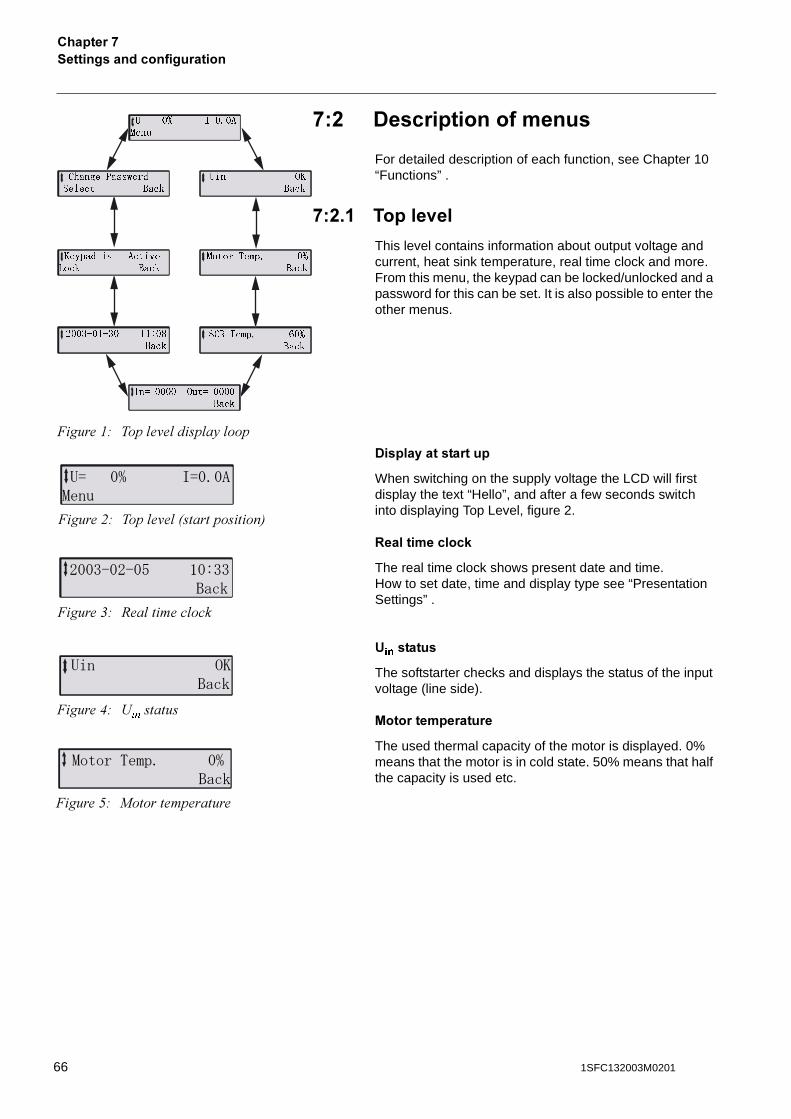
*�%� ����<��
This level contains information about output voltage and current, heat sink temperature, real time clock and more. From this menu, the keypad can be locked/unlocked and a password for this can be set. It is also possible to enter the other menus.
-���������������
When switching on the supply voltage the LCD will first display the text “Hello”, and after a few seconds switch into displaying Top Level, figure 2.
:�����������,
The real time clock shows present date and time. How to set date, time and display type see “Presentation Settings” .
&��������
The softstarter checks and displays the status of the input voltage (line side).
/���������������
The used thermal capacity of the motor is displayed. 0% means that the motor is in cold state. 50% means that half the capacity is used etc.
�����"# ��� �'� ��� �5 ���
�� �� � ������
��
�������������
����� ����
������ �� ��� !
"��� ����
� #�$%��� &��
����
��������� '��������
�����
� � '�
����
(��)*�+*)�� ++,�-
�����
�����$%�� ��
�����
�� ��� ��������
�����$# ��� �'� 8�����������9
4��56�46�/ #�755����
�����&# 6�� ���� ���
��� 2����
�����(# <��������
�����*� � ������
�����*# ����������������
66 1SFC132003M0201
������������������������
�������*
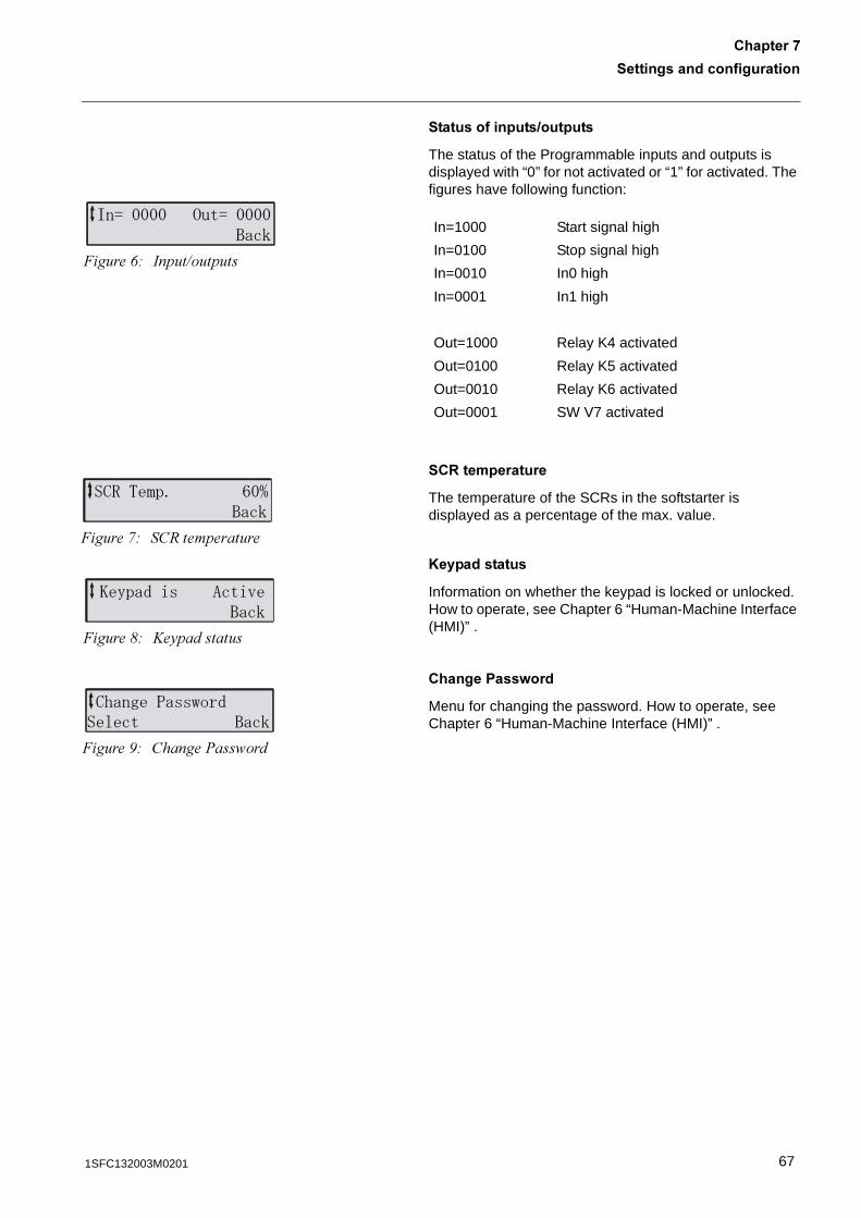
����������������������
The status of the Programmable inputs and outputs is displayed with “0” for not activated or “1” for activated. The figures have following function:
��:�����������
The temperature of the SCRs in the softstarter is displayed as a percentage of the max. value.
A�����������
Information on whether the keypad is locked or unlocked. How to operate, see Chapter 6 “Human-Machine Interface (HMI)” .
������ ���=���
Menu for changing the password. How to operate, see Chapter 6 “Human-Machine Interface (HMI)” .
In=1000 Start signal high
In=0100 Stop signal high
In=0010 In0 high
In=0001 In1 high
Out=1000 Relay K4 activated
Out=0100 Relay K5 activated
Out=0010 Relay K6 activated
Out=0001 SW V7 activated
��������� ������������
�����+# �����7�������
��&�*� �� 8������
�����,# ��6�����������
2% �'��" ����3����
�����-# @�5���������
�+������""0��'���� ����
�����.# ������%��� ���
671SFC132003M0201
�������������������������������*
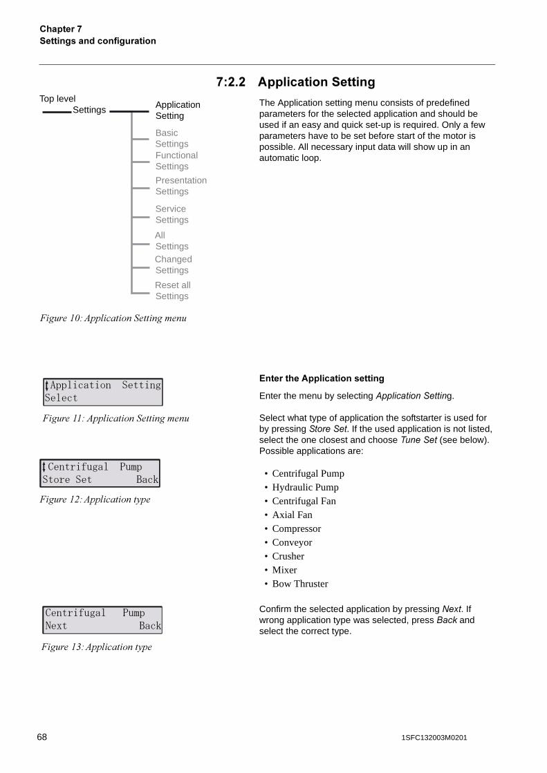
*�%�% #�����������������
The Application setting menu consists of predefined parameters for the selected application and should be used if an easy and quick set-up is required. Only a few parameters have to be set before start of the motor is possible. All necessary input data will show up in an automatic loop.
?�������#�����������������
Enter the menu by selecting�+�� ��������g.
Select what type of application the softstarter is used for by pressing �������. If the used application is not listed, select the one closest and choose ������� (see below). Possible applications are:
• Centrifugal Pump• Hydraulic Pump• Centrifugal Fan• Axial Fan• Compressor• Conveyor• Crusher• Mixer• Bow Thruster
Confirm the selected application by pressing ���. If wrong application type was selected, press����� and select the correct type.
Top levelSettings
�����"1#)�� ���������������
ApplicationSetting
BasicSettingsFunctionalSettings
ServiceSettings
PresentationSettings
AllSettingsChangedSettings
Reset allSettings
� �������� ����������
�����""# )�� ���������������
����������� ��� ������� ����
�����"$#)�� ������5��
�����"&#)�� ������5��
����������� ��� ��� ����
68 1SFC132003M0201
������������������������
�������*
���������
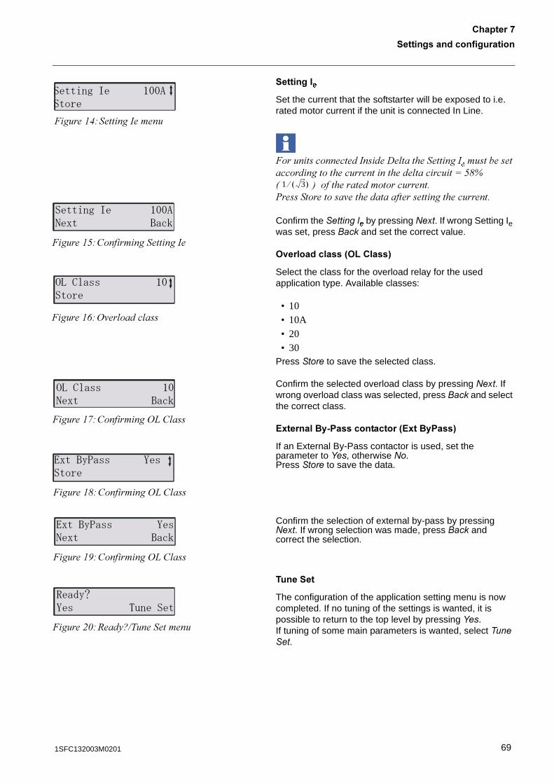
Set the current that the softstarter will be exposed to i.e. rated motor current if the unit is connected In Line.
����������������������� ������������������������������������������������ �������:*-B8 9 �����������������������%�������������'������������������������������
Confirm the ����� � by pressing ���. If wrong Setting Ie
was set, press ���� and set the correct value.
><�����������3>B�����4
Select the class for the overload relay for the used application type. Available classes:
• 10• 10A• 20• 30
Press ���� to save the selected class.
Confirm the selected overload class by pressing����. If wrong overload class was selected, press ���� and select the correct class.
?8��������2 ������������3?8��� ���4
If an External By-Pass contactor is used, set the parameter to ���, otherwise ��.Press ���� to save the data.
Confirm the selection of external by-pass by pressing ���. If wrong selection was made, press ���� and correct the selection.
������
The configuration of the application setting menu is now completed. If no tuning of the settings is wanted, it is possible to return to the top level by pressing ���. If tuning of some main parameters is wanted, select �������.
��������� #�������
�����"(#������������
��������� #������ ����
�����"*#����������������
!����""� #�����
�����"+#/'�� ���� ���
!����"" #���� ����
�����",#��������/0� ���
$����%��"" )"����
�����"-#��������/0� ���
$����%��"" )"��� ����
�����".#��������/0� ���
&�'%(�)" *�����
�����$1#6���5C7�����������
1 3� ��
691SFC132003M0201
�������������������������������*
���������������
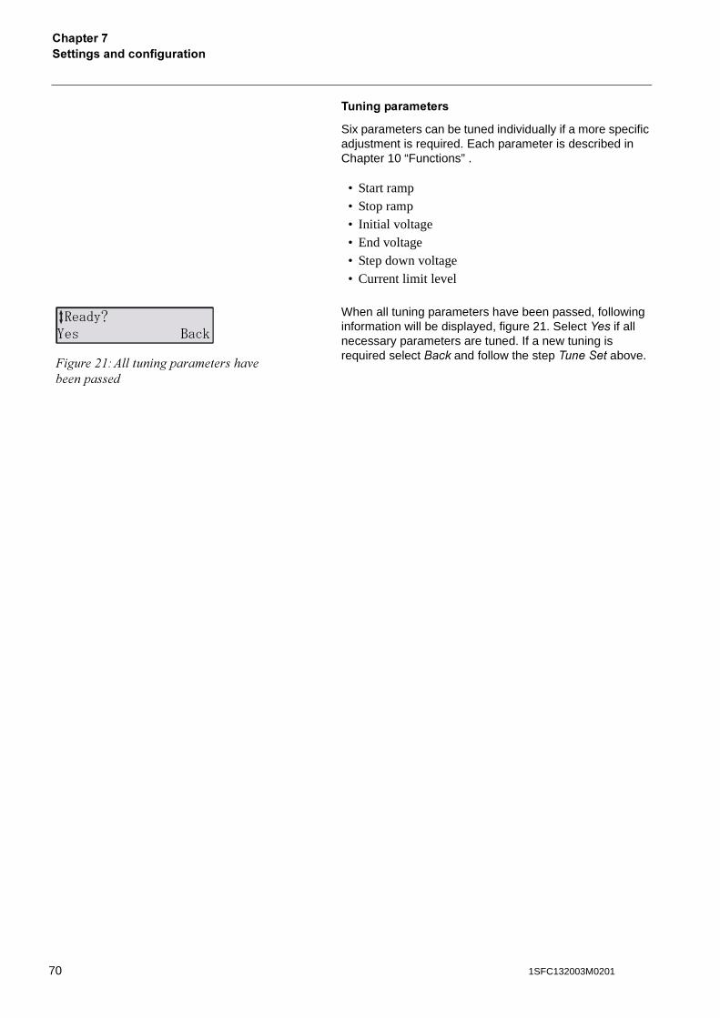
Six parameters can be tuned individually if a more specific adjustment is required. Each parameter is described in Chapter 10 “Functions” .
• Start ramp• Stop ramp• Initial voltage• End voltage• Step down voltage • Current limit level
When all tuning parameters have been passed, following information will be displayed, figure 21. Select ��� if all necessary parameters are tuned. If a new tuning is required select ���� and follow the step ������� above.
&�'%()" ����
�����$"#) �����������������'�����������
70 1SFC132003M0201
������������������������
�������*
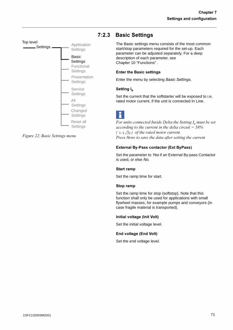
*�%�� �������������
The Basic settings menu consists of the most common start/stop parameters required for the set-up. Each parameter can be adjusted separately. For a deep description of each parameter, seeChapter 10 “Functions” .
?��������������������
Enter the menu by selecting ����������.
���������
Set the current that the softstarter will be exposed to i.e. rated motor current, if the unit is connected In Line.
����������������������� ����������������������
�������������������������� �������:*-B8 9 �����������������������%�������������'�����������������������������
?8��������2 ������������3?8��� ���4
Set the parameter to ��� if an External By-pass Contactor is used, or else ��.
���������
Set the ramp time for start.
��������
Set the ramp time for stop (softstop). Note that this function shall only be used for applications with small flywheel masses, for example pumps and conveyors (in case fragile material is transported).
�������<������3����D���4
Set the initial voltage level.
?��<������3?��D���4
Set the end voltage level.
Top levelSettings Application
Settings
BasicSettingsFunctionalSettings
ServiceSettings
PresentationSettings
AllSettingsChangedSettings
Reset allSettings
�����$$#4��������������1 3� ��
711SFC132003M0201
�������������������������������*
������=�
Set the level of the step down voltage. This function is only working if softstop is selected.
������������3�������B��4
Set the current limit level for the start.
><�����������3>B�����4
Select the class for the overload protection.
The configuration of the basic setting menu is now completed. It is possible to return to the top level by pressing ���� 3 times.
72 1SFC132003M0201
������������������������
�������*
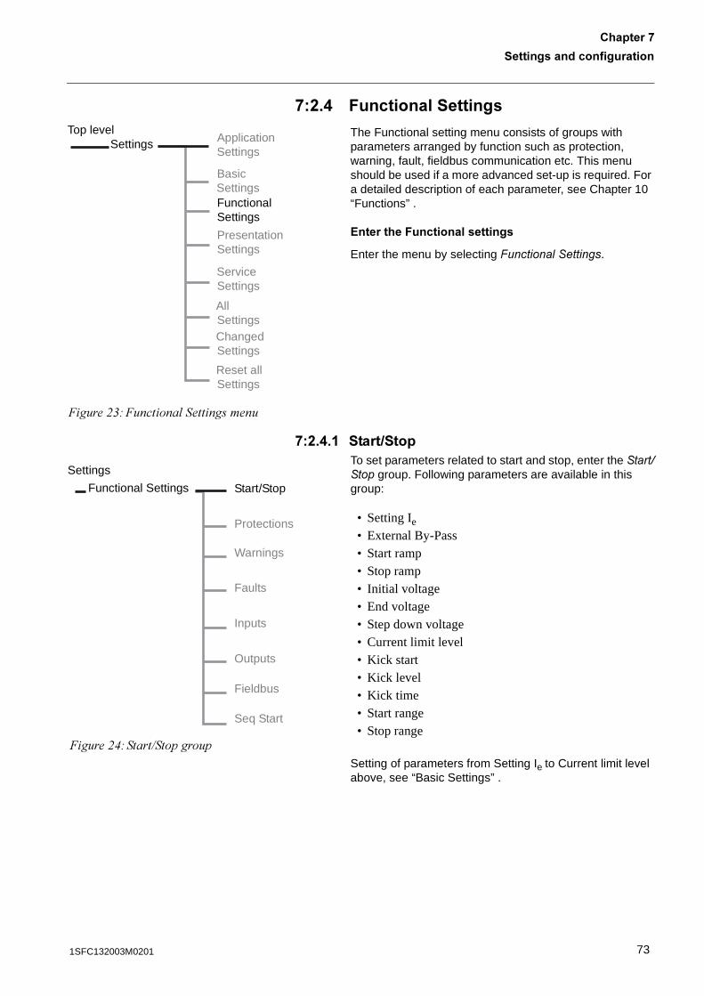
*�%�. 7�����������������
The Functional setting menu consists of groups with parameters arranged by function such as protection, warning, fault, fieldbus communication etc. This menu should be used if a more advanced set-up is required. For a detailed description of each parameter, see Chapter 10 “Functions” .
?�������7�����������������
Enter the menu by selecting "������ ������.
*�%�.� ����������To set parameters related to start and stop, enter the ������� group. Following parameters are available in this group:
• Setting Ie
• External By-Pass• Start ramp• Stop ramp• Initial voltage• End voltage• Step down voltage• Current limit level• Kick start• Kick level• Kick time• Start range• Stop range
Setting of parameters from Setting Ie to Current limit level above, see “Basic Settings” .
Top levelSettings
�����$&#�������� �����������
ApplicationSettings
BasicSettingsFunctionalSettings
ServiceSettings
PresentationSettings
AllSettingsChangedSettings
Reset allSettings
Functional Settings Start/Stop
Protections
Warnings
Inputs
Faults
Outputs
Fieldbus
�����$(#�����7���������
Settings
Seq Start
731SFC132003M0201
�������������������������������*
A��,�����
Activate the *������ function by entering this menu. Press ���� to save the selection.
A��,B�<��
Set the required level of the Kick Start. Press ���� to save the data.This menu will only be visual if Kick Start is activated.
A��,���
Set the required time for the kick start. Press ���� to save the data.This menu will only be visual if Kick Start is activated.
�����:����
The ramp time for start can be set between 1 and 30 seconds as default. If required, the range can be extended up to 120 seconds by entering this menu. Press ���� to save the data.
����:����
The ramp time for stop can be set between 0 and 30 seconds as default. If required, the range can be extended up to 120 seconds by entering this menu. Press ���� to save the data.
The configuration of the parameters in the Start/Stop group is now completed. It is possible to return to top level by pressing Back three times. To configure the protection, proceed to that menu.
74 1SFC132003M0201
������������������������
�������*
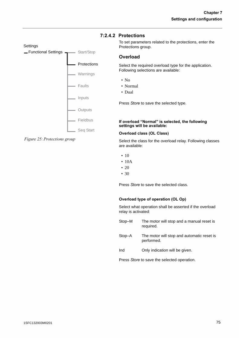
*�%�.�% ����������To set parameters related to the protections, enter the Protections group.
><������
Select the required overload type for the application. Following selections are available:
• No• Normal• Dual
Press ���� to save the selected type.
���<������E9�����F����������'��������=�����������=������<��������
><�����������3>B�����4
Select the class for the overload relay. Following classes are available:
• 10• 10A• 20• 30
Press ���� to save the selected class.
><���������������������3>B>�4
Select what operation shall be asserted if the overload relay is activated:
Stop–M The motor will stop and a manual reset is required.
Stop–A The motor will stop and automatic reset is performed.
Ind Only indication will be given.
Press ���� to save the selected operation.
Functional Settings Start/Stop
Protections
Warnings
Inputs
Faults
Outputs
Fieldbus
�����$*#%��������������
Settings
Seq Start
751SFC132003M0201
�������������������������������*
���<������E-���F����������'��������=�����������=������<��������
><����������������3>B������4
Select the required class for overload relay during start condition. Following classes are available:
• 10• 10A• 20• 30
Press ����� to save the selected class.
><��������������3>B�����:4
Select the required class for overload relay during continuos run. Following classes are available:
• 10• 10A• 20• 30
Press ����� to save the selected class.
76 1SFC132003M0201
������������������������
�������*
B��,��:����
Activate the protection if required by changing to ���.
��EG��F����������'��������=�����������=������<��������
B��,���������<��3B��,:B�<4
Set the level of the locked rotor protection.Available only if the protection is selected.
B��,�����������3B��,:���4
Set the time for the locked rotor protection.Available only if the protection is selected.
B��,����������������������3B��,:>�4
Select what operation shall be asserted if the locked rotor protection is activated:
Stop–M The motor will stop and a manual reset is required.
Stop–A The motor will stop and automatic reset is performed.
Ind Only indication will be given.
Press ���� to save the selected operation.
771SFC132003M0201
�������������������������������*
&��������
Activate the protection if required by changing to ���.
��EG��F����������'��������=�����������=������<��������
&����������<��3&�����B�<4
Set the level of the underload protection. Available only if the protection is selected.
&������������3&��������4
Set the time for the underload protection.Available only if the protection is selected.
&�����������������������3&�����>�4
Select what operation shall be asserted if the underload protection is activated:
Stop–M The motor will stop and a manual reset is required.
Stop–A The motor will stop and automatic reset is performed.
Ind Only indication will be given.
Press ���� to save the selected operation.
78 1SFC132003M0201
������������������������
�������*
�������������3 �������4
Activate the protection if required by changing to ���.
��EG��F����������'��������=�����������=������<��������
���������������<��3 ����B�<4
Set the level of the phase imbalance protection. Available only if the protection is selected.
����������������������������3 ����>�4
Select what operation shall be asserted if the phase imbalance protection is activated:
Stop–M The motor will stop and a manual reset is required.
Stop–A The motor will stop and automatic reset is performed.
Ind Only indication will be given.
Press ���� to save the selected operation.
1����������31����4
Activate the high current protection if required by changing to����.
��EG��F����������'��������=����������=������<��������
1�������������������������31����>�4
Select what operation shall be asserted if the high current protection is activated:
Stop–M The motor will stop and a manual reset is required.
Stop–A The motor will stop and automatic reset is performed.
Ind Only indication will be given.
Press ���� to save the selected operation.
791SFC132003M0201
�������������������������������*
������<�����3 ����:�<4
Activate the phase reversal protection if required by changing to ���.
��EG��F����������'��������=����������=������<��������
������<��������������������3 �:�<>�4
Select what operation shall be asserted if the phase reversal protection is activated:
Stop–M The motor will stop and a manual reset is required.
Stop–A The motor will stop and automatic reset is performed.
Ind Only indication will be given.
Press ���� to save the selected operation.
�
Activate the PTC protection if required by changing to ���.
��EG��F����������'��������=����������=������<��������
����������������3 �>�4
Select what operation shall be asserted if the PTC protection is activated:
Stop–M The motor will stop and a manual reset is required.
Stop–A The motor will stop and automatic reset is performed.
Ind Only indication will be given.
Press ���� to save the selected operation.
80 1SFC132003M0201
������������������������
�������*
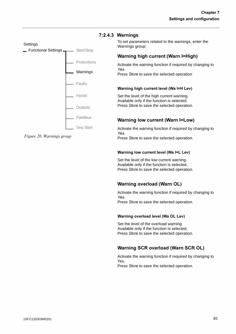
*�%�.�� (�������To set parameters related to the warnings, enter the Warnings group:
(�����������������3(����H1���4
Activate the warning function if required by changing to ���.Press ���� to save the selected operation
(�������������������<��3(��H1B�<4
Set the level of the high current warning.Available only if the function is selected.Press ���� to save the selected operation.
(��������=�������3(����HB�=4
Activate the warning function if required by changing to ���.Press ���� to save the selected operation.
(��������=���������<��3(��HBB�<4
Set the level of the low current warning.Available only if the function is selected.Press ���� to save the selected operation.
(�������<������3(���>B4
Activate the warning function if required by changing to ���.Press ���� to save the selected operation.
(�������<��������<��3(�>BB�<4
Set the level of the overload warning.Available only if the function is selected.Press ���� to save the selected operation.
(��������:�<������3(�����:>B4
Activate the warning function if required by changing to Yes.Press ���� to save the selected operation.
Functional Settings Start/Stop
Protections
Warnings
Inputs
Faults
Outputs
Fieldbus
�����$+#?�����������
Settings
Seq Start
811SFC132003M0201
�������������������������������*
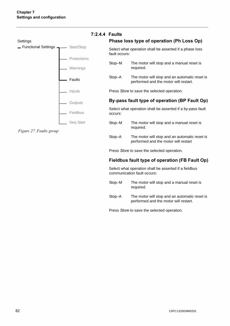
*�%�.�. 7����� �����������������������3 �B���>�4
Select what operation shall be asserted if a phase loss fault occurs:
Stop–M The motor will stop and a manual reset is required.
Stop–A The motor will stop and an automatic reset is performed and the motor will restart.
Press ���� to save the selected operation.
��2������������������������3� 7����>�4
Select what operation shall be asserted if a by-pass fault occurs:
Stop–M The motor will stop and a manual reset is required.
Stop–A The motor will stop and an automatic reset is performed and the motor will restart
Press ���� to save the selected operation.
7���������������������������37�7����>�4
Select what operation shall be asserted if a fieldbus communication fault occurs:
Stop–M The motor will stop and a manual reset is required.
Stop–A The motor will stop and an automatic reset is performed and the motor will restart.
Press ���� to save the selected operation.
Functional Settings Start/Stop
Protections
Warnings
Inputs
Faults
Outputs
Fieldbus
�����$,#��� �������
Settings
Seq Start
82 1SFC132003M0201
������������������������
�������*
7��;�������������������������37��;7>�4
Select what operation shall be asserted if the frequency fault occurs (out of range):
Stop–M The motor will stop and a manual reset is required.
Stop–A The motor will stop and an automatic reset is performed and the motor will restart.
Press ���� to save the selected operation.
1������,���������������31����>�4
Select what operation shall be asserted if an over-temperature occurs:
Stop–M The motor will stop and a manual reset is required.
Stop–A The motor will stop and an automatic reset is performed and the motor will restart
Press ���� to save the selected operation.
���������:���������������3��:��>�4
Select what operation shall be asserted if a fault occurs with shorted thyristor:
Stop–M The motor will stop and a manual reset is required.
Stop–A The motor will stop and an automatic reset is performed and the motor will restart
Press ���� to save the selected operation.
831SFC132003M0201
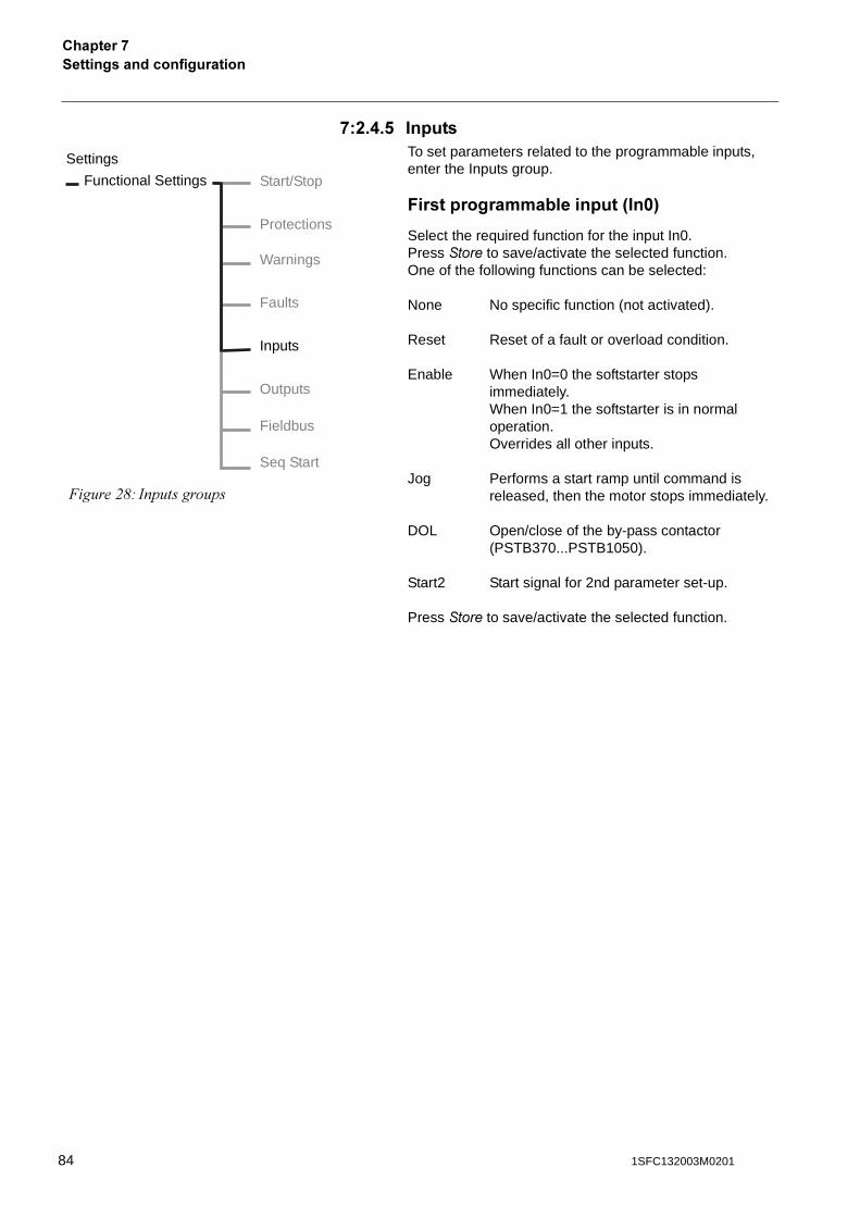
�������������������������������*
*�%�.�! ������To set parameters related to the programmable inputs, enter the Inputs group.
7���������������������3���4
Select the required function for the input In0. Press ���� to save/activate the selected function. One of the following functions can be selected:
None No specific function (not activated).
Reset Reset of a fault or overload condition.
Enable When In0=0 the softstarter stops immediately.When In0=1 the softstarter is in normal operation.Overrides all other inputs.
Jog Performs a start ramp until command is released, then the motor stops immediately.
DOL Open/close of the by-pass contactor (PSTB370...PSTB1050).
Start2 Start signal for 2nd parameter set-up.
Press ���� to save/activate the selected function.
Functional Settings Start/Stop
Protections
Warnings
Inputs
Faults
Outputs
Fieldbus
�����$-# ������������
Settings
Seq Start
84 1SFC132003M0201
������������������������
�������*
�����������������������3�� 4
Select the required function for the input In1.One of the following functions can be selected:
None No specific function (not activated).
Reset Reset of a fault or overload condition.
Enable When the In1=0 the softstarter stops immediately.When In1=1 the softstarter is in normal operation.Overrides all other inputs.
Jog Performs a start ramp until command is released, then the motor stops immediately.
DOL Open/close of the by-pass contactor (PSTB370...PSTB1050).
Start3 Start signal for 3rd parameter set-up.
Press ���� to save/activate the selected function.
851SFC132003M0201
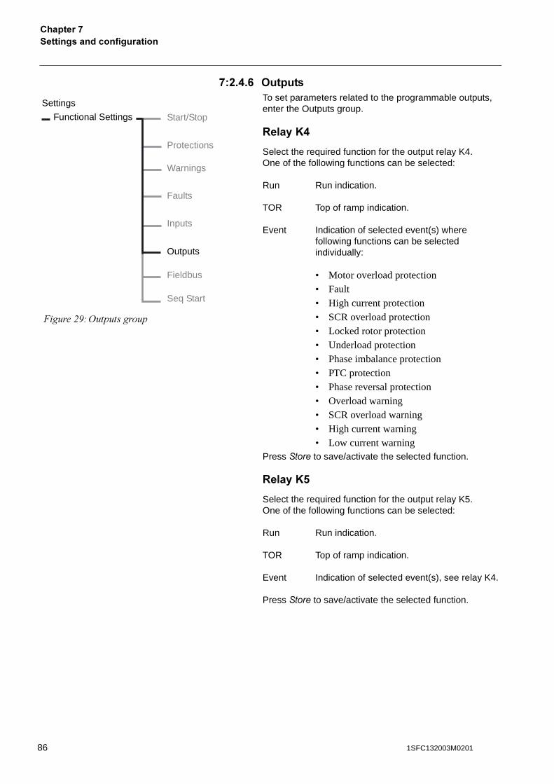
�������������������������������*
*�%�.�0 >������To set parameters related to the programmable outputs, enter the Outputs group.
:����A.
Select the required function for the output relay K4. One of the following functions can be selected:
Run Run indication.
TOR Top of ramp indication.
Event Indication of selected event(s) where following functions can be selected individually:
• Motor overload protection• Fault• High current protection• SCR overload protection• Locked rotor protection• Underload protection• Phase imbalance protection• PTC protection• Phase reversal protection• Overload warning• SCR overload warning• High current warning• Low current warning
Press ���� to save/activate the selected function.
:����A!
Select the required function for the output relay K5. One of the following functions can be selected:
Run Run indication.
TOR Top of ramp indication.
Event Indication of selected event(s), see relay K4.
Press ���� to save/activate the selected function.
Functional Settings Start/Stop
Protections
Warnings
Inputs
Faults
Outputs
Fieldbus
�����$.#/�����������
Settings
Seq Start
86 1SFC132003M0201
������������������������
�������*
:����A0
Select the required function for the output relay K6.One of the following functions can be selected:
Run Run indication.
TOR Top of ramp indication.
Event Indication of selected event(s), see relay K4.
Press ���� to save/activate the selected function.
�(>���D*
Select the required function for the fieldbus communication output SW Outp V7.One of the following functions can be selected:
Run Run indication.
TOR Top of ramp indication.
Event Indication of selected event(s), see relay K4.
Press ���� to save/activate the selected function.
871SFC132003M0201
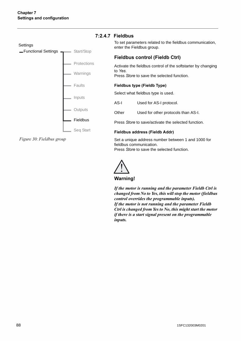
�������������������������������*
*�%�.�* 7�������To set parameters related to the fieldbus communication, enter the Fieldbus group.
7��������������37���������4
Activate the fieldbus control of the softstarter by changing to ���.Press ���� to save the selected function.
7�����������37��������4
Select what fieldbus type is used.
AS-I Used for AS-I protocol.
Other Used for other protocols than AS-I.
Press ���� to save/activate the selected function.
7��������������37�����#���4
Set a unique address number between 1 and 1000 for fieldbus communication.Press ���� to save the selected function.
(������)
)��� ����������������������� ������������/������������� ����������0�����1����� �������������� ��������2����������������"�������� ���������������������3�)��� ��������������������������� ������������/������������� ����������1������0���� ������ ��������� ������������ ���������������������������������� ����������������������
Functional Settings Start/Stop
Protections
Warnings
Inputs
Faults
Outputs
Fieldbus
�����&1#�� ���������
Settings
Seq Start
88 1SFC132003M0201
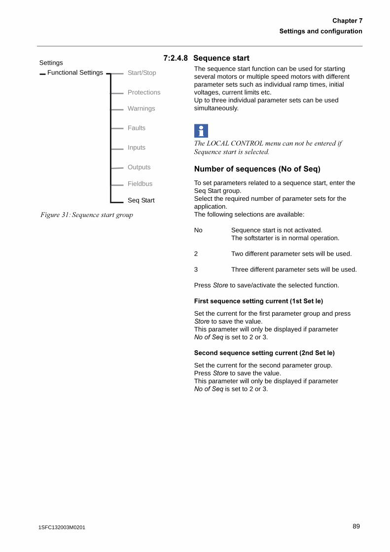
������������������������
�������*
*�%�.�6 ��;����������The sequence start function can be used for starting several motors or multiple speed motors with different parameter sets such as individual ramp times, initial voltages, current limits etc.Up to three individual parameter sets can be used simultaneously.
���0/�)0�/=�6/0����������������������;������������� ������
9���������;������39�����;4
To set parameters related to a sequence start, enter the Seq Start group.Select the required number of parameter sets for the application.The following selections are available:
No Sequence start is not activated. The softstarter is in normal operation.
2 Two different parameter sets will be used.
3 Three different parameter sets will be used.
Press ���� to save/activate the selected function.
7������;�������������������3 �������4
Set the current for the first parameter group and press ���� to save the value.This parameter will only be displayed if parameter ����0���1 is set to 2 or 3.
��������;�������������������3%�������4
Set the current for the second parameter group.Press ���� to save the value.This parameter will only be displayed if parameter ����0���1 is set to 2 or 3.
Functional Settings Start/Stop
Protections
Warnings
Inputs
Faults
Outputs
Fieldbus
�����&"#��;���������������
Settings
Seq Start
891SFC132003M0201
�������������������������������*
������;�������������������3��������4
Set the current for the third parameter group.Press ���� to save the value.
This parameter will only be displayed if parameter ����0���1 is set to 3.
7�������������������������������3���4
This parameter will automatically be set as Start2.
7��������������������������������3�� 4
This parameter will automatically be set as Start3.
><������
The overload protection is not activated when sequence start is selected.To activate the motor overload protection enter this group and change to required function.
����'�� �������������������� 5��������� ������������'��� ����������������� ���������� ��������� ������������������ ����
7������;���������������3 ����;� �����4
To set parameters related to the first sequence, enter the 1st Seq. Param. group.Following parameters can be adjusted:
'����� � Setting current.
����2���' Ramp time for start
��3� ' Initial voltage.
$����/�' Current limit level.
Press ���� to save the selected parameter.
90 1SFC132003M0201
������������������������
�������*
��������;���������������3%����;� �����4
To set parameters related to the second sequence, enter the 2nd Seq. Param. group.Following parameters can be adjusted:
(������ � Setting current.
����2���( Ramp time for start.
��3� ( Initial voltage.
$����/�( Current limit.
Press ���� to save the selected parameter.
������;���������������3�����;� �����4
To set parameters related to the third sequence, enter the 3rd Seq. Param. group.Following parameters can be adjusted:
4������ � Setting current.
����2���4 Ramp time for start.
��3� 4 Initial voltage.
$����/�4 Current limit.
Press ���� to save the selected parameter.
911SFC132003M0201
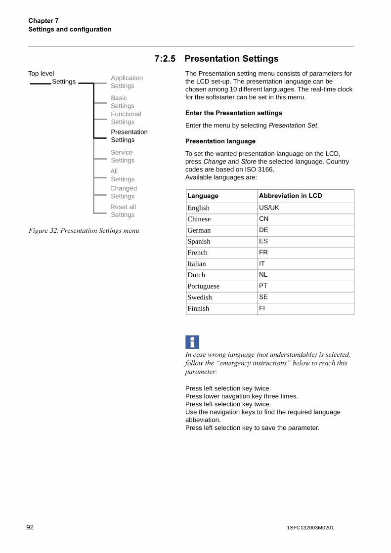
�������������������������������*
*�%�! �������������������
The Presentation setting menu consists of parameters for the LCD set-up. The presentation language can be chosen among 10 different languages. The real-time clock for the softstarter can be set in this menu.
?������� �������������������
Enter the menu by selecting ������������.
�������������������
To set the wanted presentation language on the LCD, press $����� and ���� the selected language. Country codes are based on ISO 3166.Available languages are:
������ ���� �������8��������������� �9��� �����!�� � ���D��������5����������E�� � �������������������#
Press left selection key twice.Press lower navgation key three times.Press left selection key twice.Use the navigation keys to find the required language abbeviation.Press left selection key to save the parameter.
Top levelSettings Application
Settings
BasicSettingsFunctionalSettings
ServiceSettings
PresentationSettings
AllSettingsChangedSettings
Reset allSettings
�����&$#%���������������������
B������� #����<��������B�-
English US/UK
Chinese CN
German DE
Spanish ES
French FR
Italian IT
Dutch NL
Portuguese PT
Swedish SE
Finnish FI
92 1SFC132003M0201
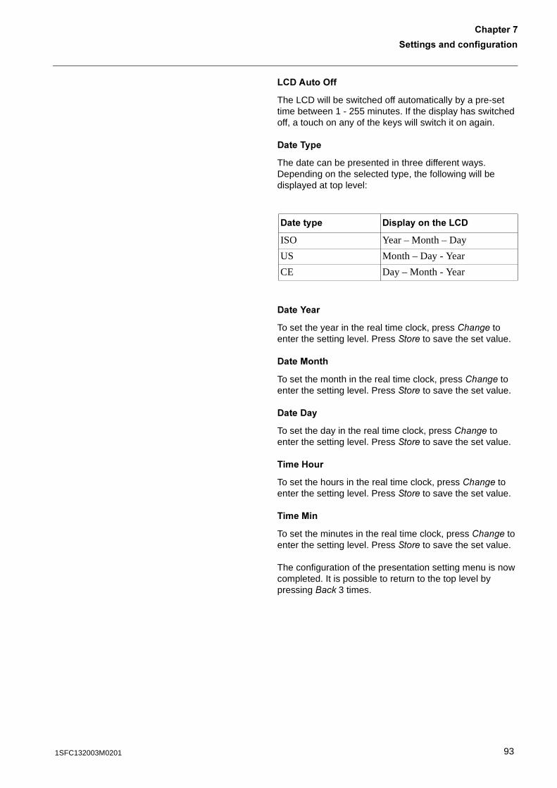
������������������������
�������*
B�-#���>��
The LCD will be switched off automatically by a pre-set time between 1 - 255 minutes. If the display has switched off, a touch on any of the keys will switch it on again.
-������
The date can be presented in three different ways. Depending on the selected type, the following will be displayed at top level:
-���G���
To set the year in the real time clock, press $����� to enter the setting level. Press ���� to save the set value.
-���/����
To set the month in the real time clock, press $����� to enter the setting level. Press �����to save the set value.
-���-��
To set the day in the real time clock, press $����� to enter the setting level. Press ���� to save the set value.
���1���
To set the hours in the real time clock, press $����� to enter the setting level. Press ���� to save the set value.
���/��
To set the minutes in the real time clock, press $����� to enter the setting level. Press ���� to save the set value.
The configuration of the presentation setting menu is now completed. It is possible to return to the top level by pressing ���� 3 times.
-������� -�����������B�-
ISO Year – Month – Day
US Month – Day - Year
CE Day – Month - Year
931SFC132003M0201
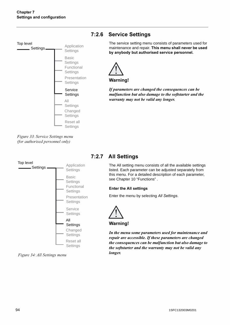
�������������������������������*
*�%�0 ���<�����������
The service setting menu consists of parameters used for maintenance and repair. ��������������<���������������������������������<�������������
(������)
)����������������� ������ ������������������������������������������������� ������������������ ����������������������"���������������
*�%�* #����������
The All setting menu consists of all the available settings listed. Each parameter can be adjusted separately from this menu. For a detailed description of each parameter, see Chapter 10 “Functions” .
?�������#����������
Enter the menu by selecting + ������.
(������)
)��� ������������������������������������������������������������������)��� ������������������� ������ ������������������������������������������������� ������������������ ����������������������"���������������
Top levelSettings Application
Settings
BasicSettingsFunctionalSettings
ServiceSettings
PresentationSettings
AllSettingsChangedSettings
Reset allSettings
�����&&#���'�������������8�������������������� �� 59
Top levelSettings Application
Settings
BasicSettingsFunctionalSettings
ServiceSettings
PresentationSettings
AllSettingsChangedSettings
Reset allSettings
�����&(#) �����������
94 1SFC132003M0201
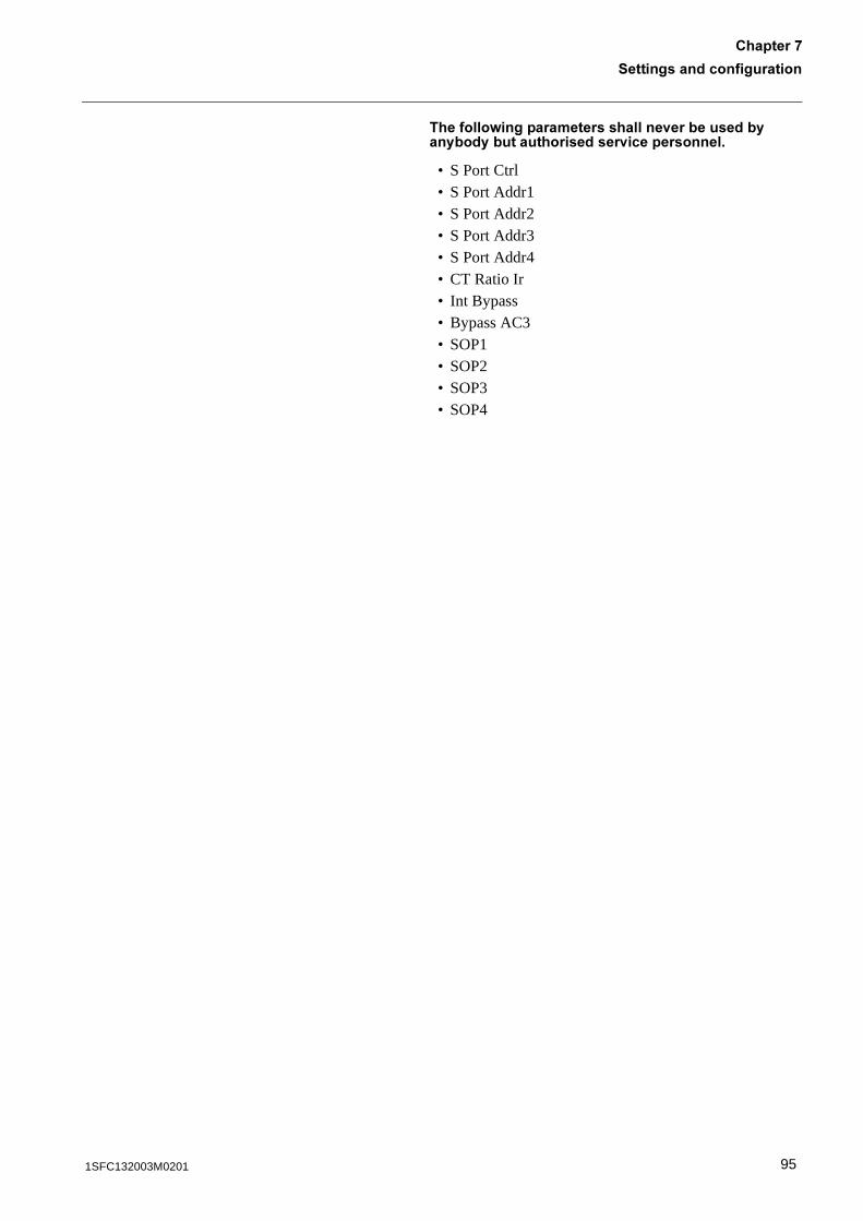
������������������������
�������*
�������=��������������������<���������������������������������<�������������
• S Port Ctrl• S Port Addr1• S Port Addr2• S Port Addr3• S Port Addr4• CT Ratio Ir• Int Bypass• Bypass AC3• SOP1• SOP2• SOP3• SOP4
951SFC132003M0201
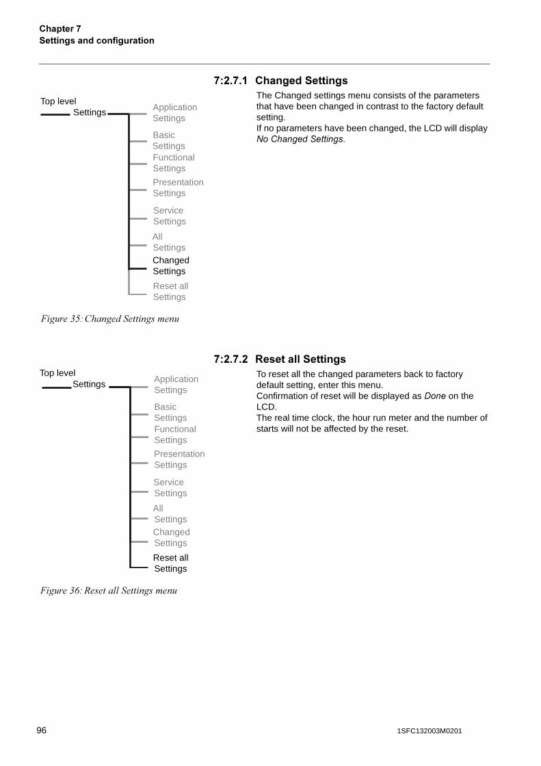
�������������������������������*
*�%�*� ���������������The Changed settings menu consists of the parameters that have been changed in contrast to the factory default setting.If no parameters have been changed, the LCD will display ���$������������.
*�%�*�% :���������������To reset all the changed parameters back to factory default setting, enter this menu.Confirmation of reset will be displayed as -��� on the LCD.The real time clock, the hour run meter and the number of starts will not be affected by the reset.
Top levelSettings Application
Settings
BasicSettingsFunctionalSettings
ServiceSettings
PresentationSettings
AllSettingsChangedSettings
Reset allSettings
�����&*#������������������
Top levelSettings Application
Settings
BasicSettingsFunctionalSettings
ServiceSettings
PresentationSettings
AllSettingsChangedSettings
Reset allSettings
�����&+#6����� �����������
96 1SFC132003M0201
7��������������������3������4
�������67��������������������3������4
Overview............................................................................................................ 99
Required accessories ................................................................................... 99AS-I............................................................................................................. 100
Binary input telegram ............................................................................ 101Binary output telegram .......................................................................... 101
DeviceNet ................................................................................................... 102Binary input telegram ............................................................................ 103Analog input telegram ........................................................................... 104Diagnostic inputs ................................................................................... 105Binary output telegram .......................................................................... 106Analog output telegram ......................................................................... 107Input address map................................................................................. 107Output address map.............................................................................. 108Parameters ............................................................................................ 109
971SFC132003M0201

98 1SFC132003M0201
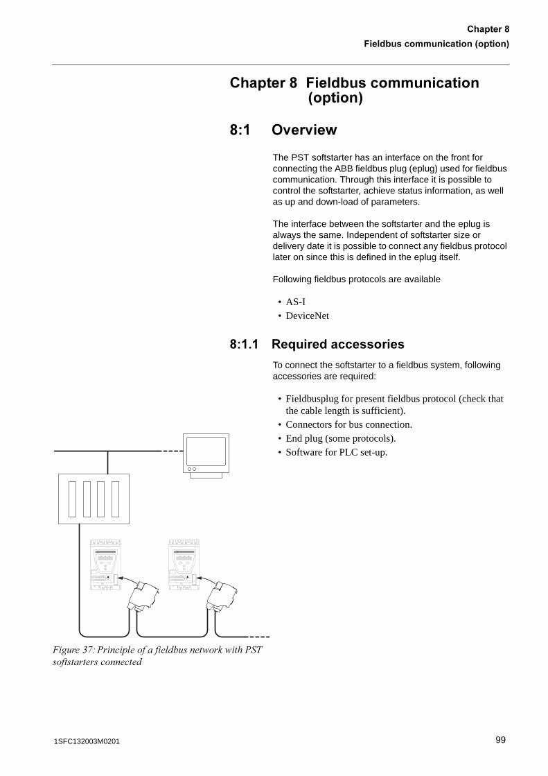
7��������������������3������4
�������6
�������67��������������������3������4
6� ><��<��=
The PST softstarter has an interface on the front for connecting the ABB fieldbus plug (eplug) used for fieldbus communication. Through this interface it is possible to control the softstarter, achieve status information, as well as up and down-load of parameters.
The interface between the softstarter and the eplug is always the same. Independent of softstarter size or delivery date it is possible to connect any fieldbus protocol later on since this is defined in the eplug itself.
Following fieldbus protocols are available
• AS-I• DeviceNet
6� � :�;����������������
To connect the softstarter to a fieldbus system, following accessories are required:
• Fieldbusplug for present fieldbus protocol (check that the cable length is sufficient).
• Connectors for bus connection.• End plug (some protocols).• Software for PLC set-up.
�����&,#%���� ������ ������� ��� ��%�����������������������
991SFC132003M0201
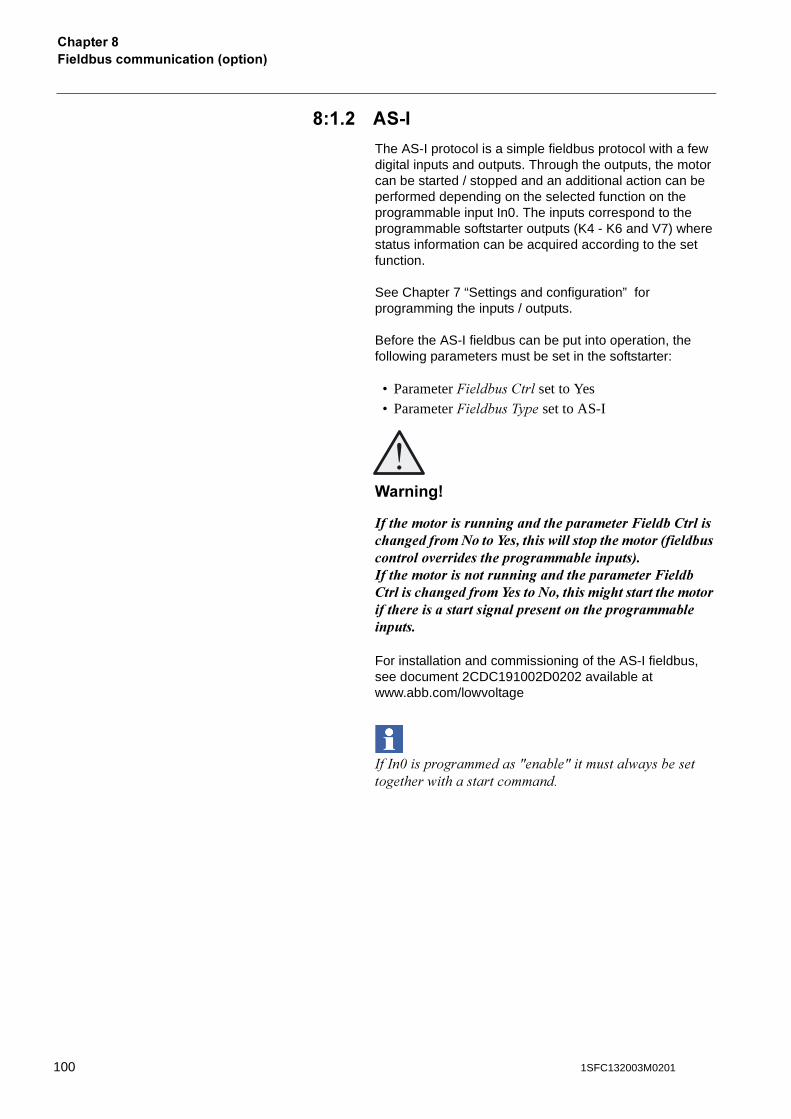
7��������������������3������4�������6
6� �% #�2�
The AS-I protocol is a simple fieldbus protocol with a few digital inputs and outputs. Through the outputs, the motor can be started / stopped and an additional action can be performed depending on the selected function on the programmable input In0. The inputs correspond to the programmable softstarter outputs (K4 - K6 and V7) where status information can be acquired according to the set function.
See Chapter 7 “Settings and configuration” for programming the inputs / outputs.
Before the AS-I fieldbus can be put into operation, the following parameters must be set in the softstarter:
• Parameter �� ������� set to Yes• Parameter �� �����5�� set to AS-I
(������)
)��� ����������������������� ������������/������������� ����������0�����1����� �������������� ��������2����������������"�������� ���������������������3�)��� ��������������������������� ������������/������������� ����������1������0���� ������ ��������� ������������ ���������������������������������� ����������������������
For installation and commissioning of the AS-I fieldbus, see document 2CDC191002D0202 available at www.abb.com/lowvoltage
����1�������������F���� �F������ �5�������������� ����������������
100 1SFC132003M0201
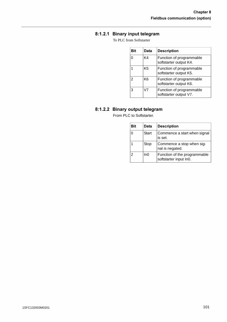
7��������������������3������4
�������6
6� �%� �������������������To PLC from Softstarter
6� �%�% ��������������������From PLC to Softstarter.
��� -��� -����������
0 K4 Function of programmable softstarter output K4.
1 K5 Function of programmable softstarter output K5.
2 K6 Function of programmable softstarter output K6.
3 V7 Function of programmable softstarter output V7.
��� -��� -����������
0 Start Commence a start when signal is set.
1 Stop Commence a stop when sig-nal is negated.
2 In0 Function of the programmable softstarter input In0.
1011SFC132003M0201
7��������������������3������4�������6
6� �� -�<���9��
The DeviceNet protocol is a fieldbus protocol that provides full control and status information on the softstarter as well as reading and writing of parameters. Through the fieldbus it is possible to start and stop the motor, perform jog, sequence start, read out currents and frequency, acquire information about protections, warnings, faults and much more.See chapter 7 “Settings and configuration” for programming the inputs / outputs.
Before the DeviceNet fieldbus can be put into operation, the following parameters must be set in the softstarter:
• Parameter �� ������� set to Yes• Parameter �� �����5��set to other• Parameter �� ����)��� set to a free communication
address.
(������)
)��� ����������������������� ������������/������������� ����������0�����1����� �������������� ��������2����������������"�������� ���������������������3�)��� ��������������������������� ������������/������������� ����������1������0���� ������ ��������� ������������ ���������������������������������� ����������������������
For installation and commissioning of the DeviceNet fieldbus, see document 2CDC193002D0201 available at www.abb.com/lowvoltage.
�����������������%0�!���������� ������;����! �����'� �� �����������������������0������������������������ ����������� ������5�������� �����'��!� �����������5��� ��� )44������
102 1SFC132003M0201
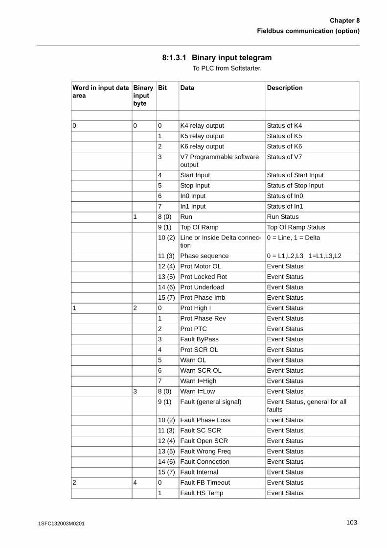
7��������������������3������4
�������6
6� ��� �������������������To PLC from Softstarter.
(������������������
���������������
��� -��� -����������
0 0 0 K4 relay output Status of K4
1 K5 relay output Status of K5
2 K6 relay output Status of K6
3 V7 Programmable software output
Status of V7
4 Start Input Status of Start Input
5 Stop Input Status of Stop Input
6 In0 Input Status of In0
7 In1 Input Status of In1
1 8 (0) Run Run Status
9 (1) Top Of Ramp Top Of Ramp Status
10 (2) Line or Inside Delta connec-tion
0 = Line, 1 = Delta
11 (3) Phase sequence 0 = L1,L2,L3 1=L1,L3,L2
12 (4) Prot Motor OL Event Status
13 (5) Prot Locked Rot Event Status
14 (6) Prot Underload Event Status
15 (7) Prot Phase Imb Event Status
1 2 0 Prot High I Event Status
1 Prot Phase Rev Event Status
2 Prot PTC Event Status
3 Fault ByPass Event Status
4 Prot SCR OL Event Status
5 Warn OL Event Status
6 Warn SCR OL Event Status
7 Warn I=High Event Status
3 8 (0) Warn I=Low Event Status
9 (1) Fault (general signal) Event Status, general for all faults
10 (2) Fault Phase Loss Event Status
11 (3) Fault SC SCR Event Status
12 (4) Fault Open SCR Event Status
13 (5) Fault Wrong Freq Event Status
14 (6) Fault Connection Event Status
15 (7) Fault Internal Event Status
2 4 0 Fault FB Timeout Event Status
1 Fault HS Temp Event Status
1031SFC132003M0201
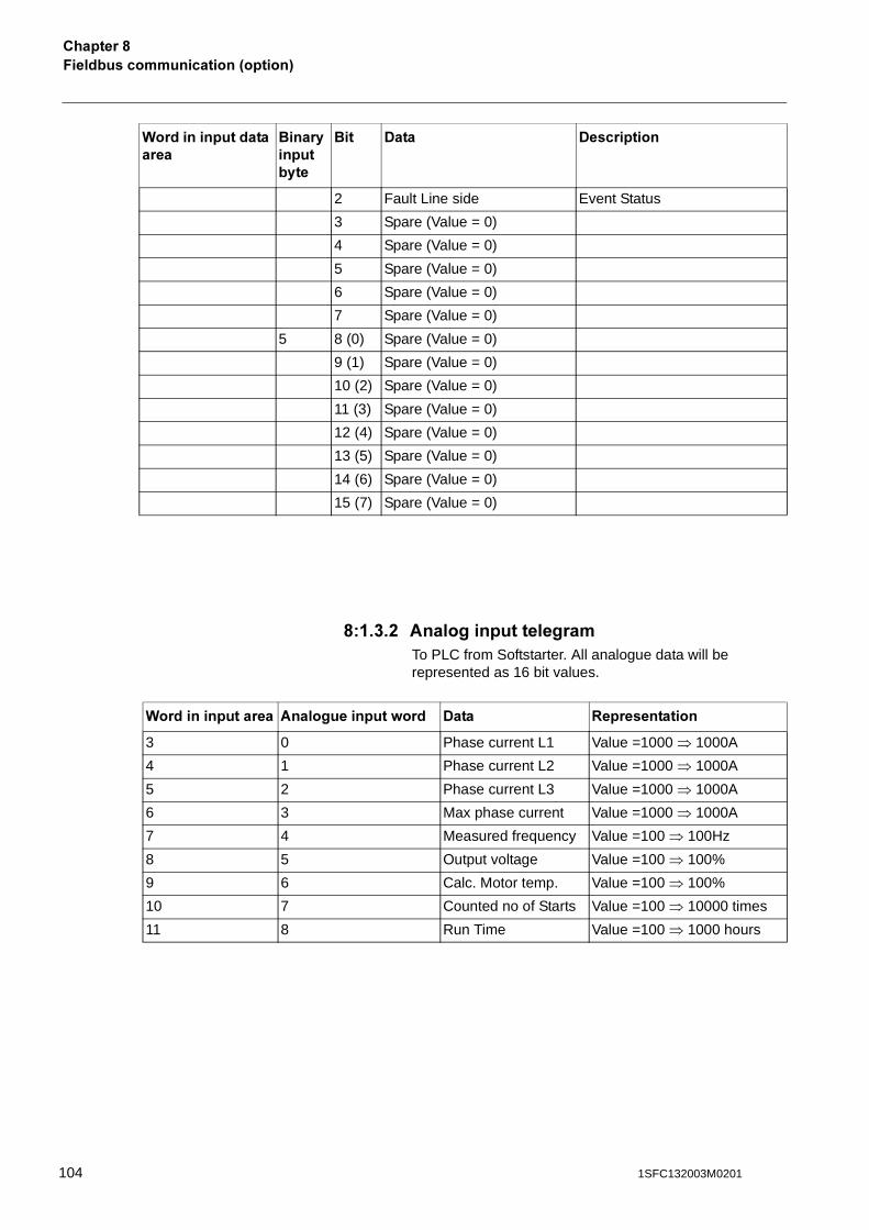
7��������������������3������4�������6
6� ���% #������������������To PLC from Softstarter. All analogue data will be represented as 16 bit values.
2 Fault Line side Event Status
3 Spare (Value = 0)
4 Spare (Value = 0)
5 Spare (Value = 0)
6 Spare (Value = 0)
7 Spare (Value = 0)
5 8 (0) Spare (Value = 0)
9 (1) Spare (Value = 0)
10 (2) Spare (Value = 0)
11 (3) Spare (Value = 0)
12 (4) Spare (Value = 0)
13 (5) Spare (Value = 0)
14 (6) Spare (Value = 0)
15 (7) Spare (Value = 0)
(������������������
���������������
��� -��� -����������
(�������������� #������������=��� -��� :�������������
3 0 Phase current L1 Value =1000 � 1000A
4 1 Phase current L2 Value =1000 � 1000A
5 2 Phase current L3 Value =1000 � 1000A
6 3 Max phase current Value =1000 � 1000A
7 4 Measured frequency Value =100 � 100Hz
8 5 Output voltage Value =100 � 100%
9 6 Calc. Motor temp. Value =100 � 100%
10 7 Counted no of Starts Value =100 � 10000 times
11 8 Run Time Value =100 � 1000 hours
104 1SFC132003M0201
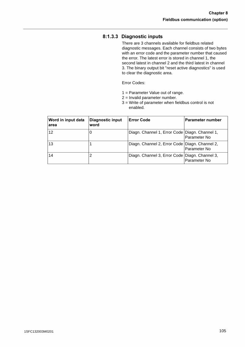
7��������������������3������4
�������6
6� ���� -���������������There are 3 channels available for fieldbus related diagnostic messages. Each channel consists of two bytes with an error code and the parameter number that caused the error. The latest error is stored in channel 1, the second latest in channel 2 and the third latest in channel 3. The binary output bit "reset active diagnostics" is used to clear the diagnostic area.
Error Codes:
1 = Parameter Value out of range.2 = Invalid parameter number.3 = Write of parameter when fieldbus control is not
enabled.
(������������������
-��������������=���
?�������� ��������������
12 0 Diagn. Channel 1, Error Code Diagn. Channel 1, Parameter No
13 1 Diagn. Channel 2, Error Code Diagn. Channel 2, Parameter No
14 2 Diagn. Channel 3, Error Code Diagn. Channel 3, Parameter No
1051SFC132003M0201
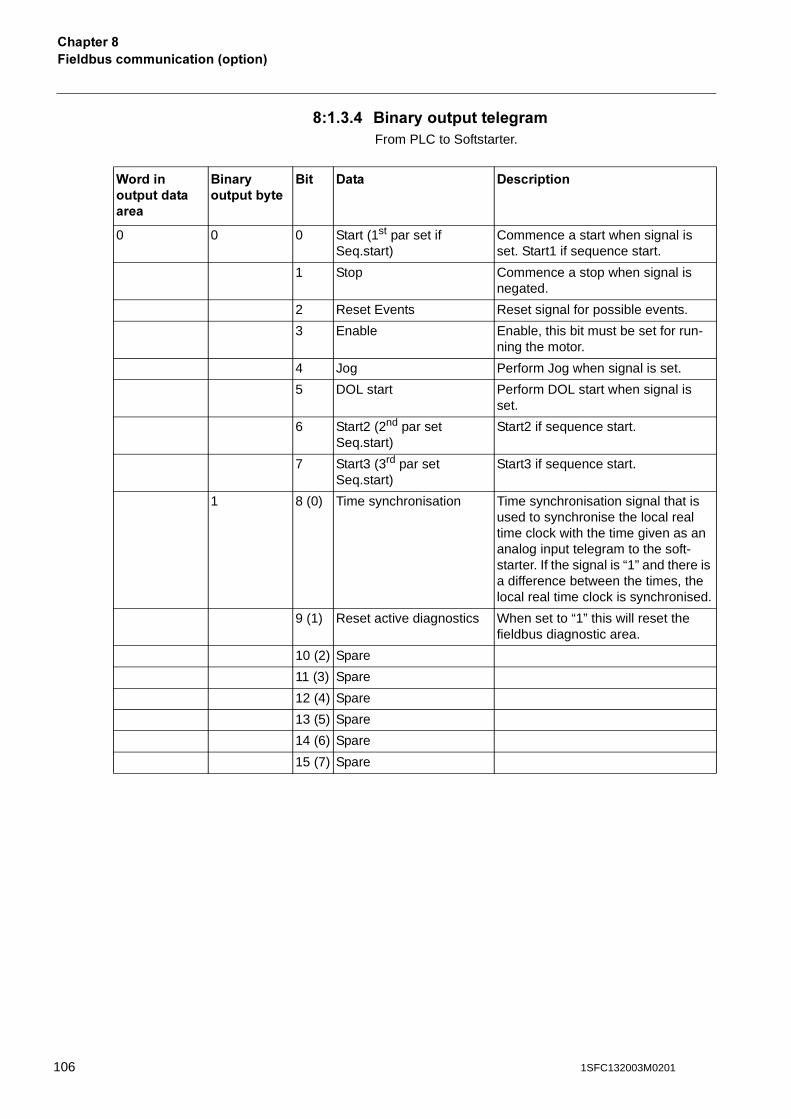
7��������������������3������4�������6
6� ���. ��������������������From PLC to Softstarter.
(�������������������
����������������
��� -��� -����������
0 0 0 Start (1st par set if Seq.start)
Commence a start when signal is set. Start1 if sequence start.
1 Stop Commence a stop when signal is negated.
2 Reset Events Reset signal for possible events.
3 Enable Enable, this bit must be set for run-ning the motor.
4 Jog Perform Jog when signal is set.
5 DOL start Perform DOL start when signal is set.
6 Start2 (2nd par set Seq.start)
Start2 if sequence start.
7 Start3 (3rd par set Seq.start)
Start3 if sequence start.
1 8 (0) Time synchronisation Time synchronisation signal that is used to synchronise the local real time clock with the time given as an analog input telegram to the soft-starter. If the signal is “1” and there is a difference between the times, the local real time clock is synchronised.
9 (1) Reset active diagnostics When set to “1” this will reset the fieldbus diagnostic area.
10 (2) Spare
11 (3) Spare
12 (4) Spare
13 (5) Spare
14 (6) Spare
15 (7) Spare
106 1SFC132003M0201
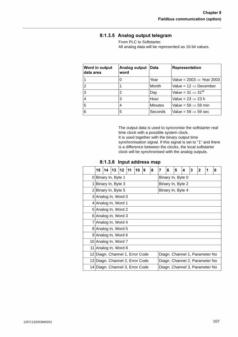
7��������������������3������4
�������6
6� ���! #�������������������From PLC to Softstarter.All analog data will be represented as 16 bit values.
The output data is used to syncronise the softstarter real time clock with a possible system clock. It is used together with the binary output time synchronisation signal. If this signal is set to "1" and there is a difference between the clocks, the local softstarter clock will be synchronised with the analog outputs.
6� ���0 ���������������
(�������������������
#�����������=���
-��� :�������������
1 0 Year Value = 2003 � Year 2003
2 1 Month Value = 12 � December
3 2 Day Value = 31 � 31st
4 3 Hour Value = 23 � 23 h
5 4 Minutes Value = 59 � 59 min
6 5 Seconds Value = 59 � 59 sec
! . � % � 5 6 * 0 ! . � % �
0 Binary In, Byte 1 Binary In, Byte 0
1 Binary In, Byte 3 Binary In, Byte 2
2 Binary In, Byte 5 Binary In, Byte 4
3 Analog In, Word 0
4 Analog In, Word 1
5 Analog In, Word 2
6 Analog In, Word 3
7 Analog In, Word 4
8 Analog In, Word 5
9 Analog In, Word 6
10 Analog In, Word 7
11 Analog In, Word 8
12 Diagn. Channel 1, Error Code Diagn. Channel 1, Parameter No
13 Diagn. Channel 2, Error Code Diagn. Channel 2, Parameter No
14 Diagn. Channel 3, Error Code Diagn. Channel 3, Parameter No
1071SFC132003M0201

7��������������������3������4�������6
6� ���* >���������������
! . � % � 5 6 * 0 ! . � % �
0 Binary Out, Byte 1 Binary Out, Byte 0
1 Analog Out, Word 0
2 Analog Out, Word 1
3 Analog Out, Word 2
4 Analog Out, Word 3
5 Analog Out, Word 4
6 Analog Out, Word 5
108 1SFC132003M0201
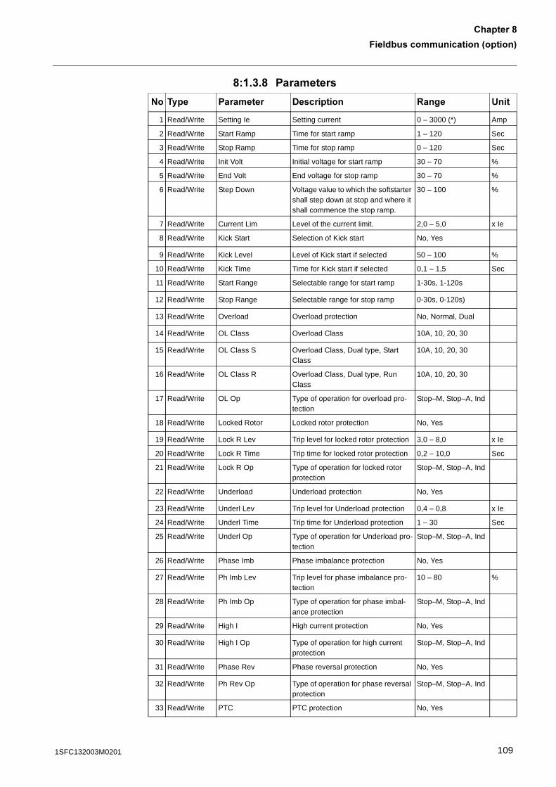
7��������������������3������4
�������6
6� ���6 ���������
9� ��� �������� -���������� :���� &���
1 Read/Write Setting Ie Setting current 0 – 3000 (*) Amp
2 Read/Write Start Ramp Time for start ramp 1 – 120 Sec
3 Read/Write Stop Ramp Time for stop ramp 0 – 120 Sec
4 Read/Write Init Volt Initial voltage for start ramp 30 – 70 %
5 Read/Write End Volt End voltage for stop ramp 30 – 70 %
6 Read/Write Step Down Voltage value to which the softstarter shall step down at stop and where it shall commence the stop ramp.
30 – 100 %
7 Read/Write Current Lim Level of the current limit. 2,0 – 5,0 x Ie
8 Read/Write Kick Start Selection of Kick start No, Yes
9 Read/Write Kick Level Level of Kick start if selected 50 – 100 %
10 Read/Write Kick Time Time for Kick start if selected 0,1 – 1,5 Sec
11 Read/Write Start Range Selectable range for start ramp 1-30s, 1-120s
12 Read/Write Stop Range Selectable range for stop ramp 0-30s, 0-120s)
13 Read/Write Overload Overload protection No, Normal, Dual
14 Read/Write OL Class Overload Class 10A, 10, 20, 30
15 Read/Write OL Class S Overload Class, Dual type, Start Class
10A, 10, 20, 30
16 Read/Write OL Class R Overload Class, Dual type, Run Class
10A, 10, 20, 30
17 Read/Write OL Op Type of operation for overload pro-tection
Stop–M, Stop–A, Ind
18 Read/Write Locked Rotor Locked rotor protection No, Yes
19 Read/Write Lock R Lev Trip level for locked rotor protection 3,0 – 8,0 x Ie
20 Read/Write Lock R Time Trip time for locked rotor protection 0,2 – 10,0 Sec
21 Read/Write Lock R Op Type of operation for locked rotor protection
Stop–M, Stop–A, Ind
22 Read/Write Underload Underload protection No, Yes
23 Read/Write Underl Lev Trip level for Underload protection 0,4 – 0,8 x Ie
24 Read/Write Underl Time Trip time for Underload protection 1 – 30 Sec
25 Read/Write Underl Op Type of operation for Underload pro-tection
Stop–M, Stop–A, Ind
26 Read/Write Phase Imb Phase imbalance protection No, Yes
27 Read/Write Ph Imb Lev Trip level for phase imbalance pro-tection
10 – 80 %
28 Read/Write Ph Imb Op Type of operation for phase imbal-ance protection
Stop–M, Stop–A, Ind
29 Read/Write High I High current protection No, Yes
30 Read/Write High I Op Type of operation for high current protection
Stop–M, Stop–A, Ind
31 Read/Write Phase Rev Phase reversal protection No, Yes
32 Read/Write Ph Rev Op Type of operation for phase reversal protection
Stop–M, Stop–A, Ind
33 Read/Write PTC PTC protection No, Yes
1091SFC132003M0201
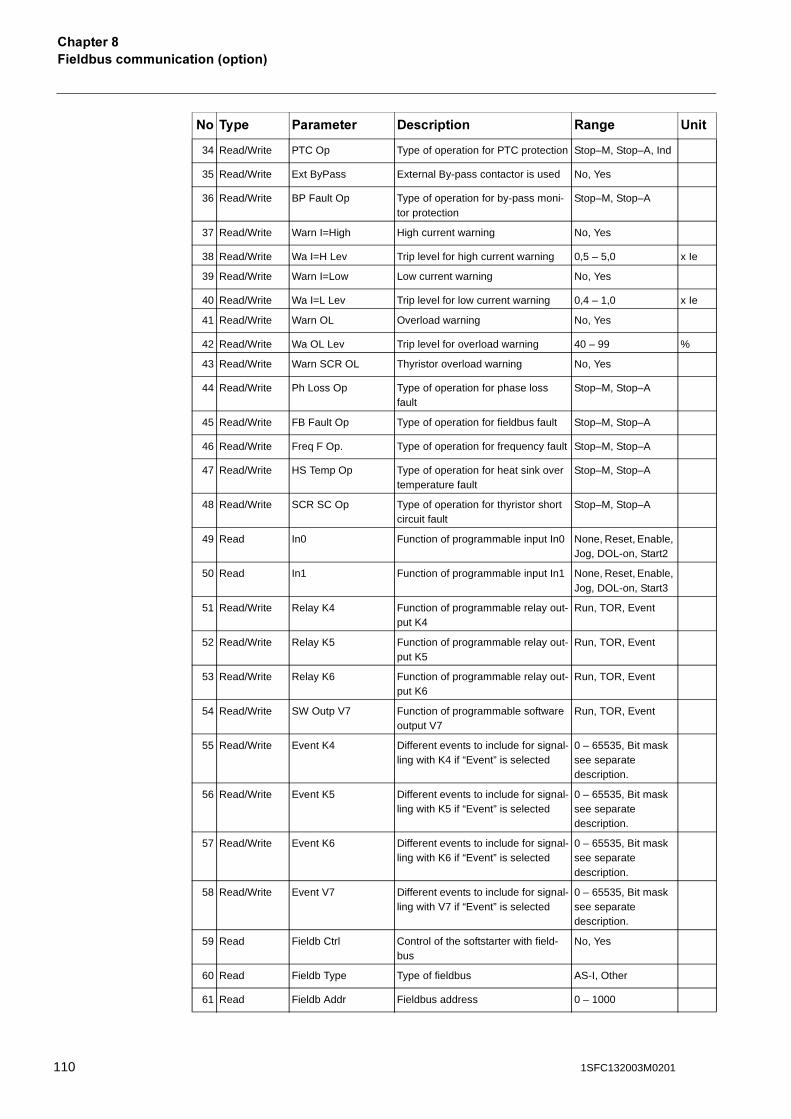
7��������������������3������4�������6
34 Read/Write PTC Op Type of operation for PTC protection Stop–M, Stop–A, Ind
35 Read/Write Ext ByPass External By-pass contactor is used No, Yes
36 Read/Write BP Fault Op Type of operation for by-pass moni-tor protection
Stop–M, Stop–A
37 Read/Write Warn I=High High current warning No, Yes
38 Read/Write Wa I=H Lev Trip level for high current warning 0,5 – 5,0 x Ie
39 Read/Write Warn I=Low Low current warning No, Yes
40 Read/Write Wa I=L Lev Trip level for low current warning 0,4 – 1,0 x Ie
41 Read/Write Warn OL Overload warning No, Yes
42 Read/Write Wa OL Lev Trip level for overload warning 40 – 99 %
43 Read/Write Warn SCR OL Thyristor overload warning No, Yes
44 Read/Write Ph Loss Op Type of operation for phase loss fault
Stop–M, Stop–A
45 Read/Write FB Fault Op Type of operation for fieldbus fault Stop–M, Stop–A
46 Read/Write Freq F Op. Type of operation for frequency fault Stop–M, Stop–A
47 Read/Write HS Temp Op Type of operation for heat sink over temperature fault
Stop–M, Stop–A
48 Read/Write SCR SC Op Type of operation for thyristor short circuit fault
Stop–M, Stop–A
49 Read In0 Function of programmable input In0 None, Reset, Enable, Jog, DOL-on, Start2
50 Read In1 Function of programmable input In1 None, Reset, Enable, Jog, DOL-on, Start3
51 Read/Write Relay K4 Function of programmable relay out-put K4
Run, TOR, Event
52 Read/Write Relay K5 Function of programmable relay out-put K5
Run, TOR, Event
53 Read/Write Relay K6 Function of programmable relay out-put K6
Run, TOR, Event
54 Read/Write SW Outp V7 Function of programmable software output V7
Run, TOR, Event
55 Read/Write Event K4 Different events to include for signal-ling with K4 if “Event” is selected
0 – 65535, Bit mask see separate description.
56 Read/Write Event K5 Different events to include for signal-ling with K5 if “Event” is selected
0 – 65535, Bit mask see separate description.
57 Read/Write Event K6 Different events to include for signal-ling with K6 if “Event” is selected
0 – 65535, Bit mask see separate description.
58 Read/Write Event V7 Different events to include for signal-ling with V7 if “Event” is selected
0 – 65535, Bit mask see separate description.
59 Read Fieldb Ctrl Control of the softstarter with field-bus
No, Yes
60 Read Fieldb Type Type of fieldbus AS-I, Other
61 Read Fieldb Addr Fieldbus address 0 – 1000
9� ��� �������� -���������� :���� &���
110 1SFC132003M0201
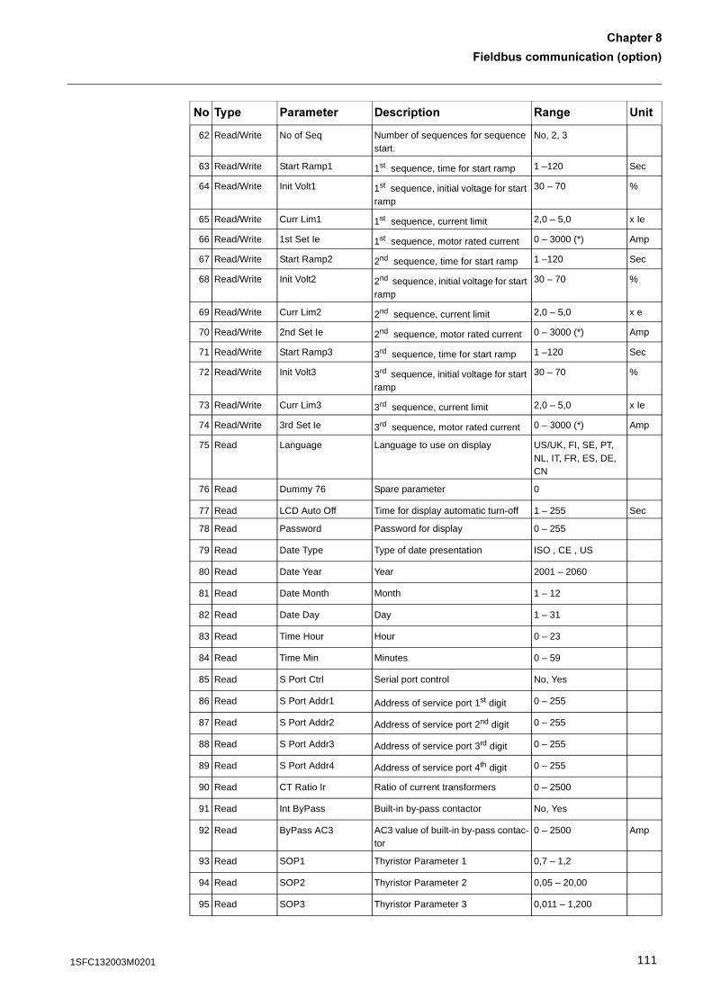
7��������������������3������4
�������6
62 Read/Write No of Seq Number of sequences for sequence start.
No, 2, 3
63 Read/Write Start Ramp1 1st sequence, time for start ramp 1 –120 Sec
64 Read/Write Init Volt1 1st sequence, initial voltage for start ramp
30 – 70 %
65 Read/Write Curr Lim1 1st sequence, current limit 2,0 – 5,0 x Ie
66 Read/Write 1st Set Ie 1st sequence, motor rated current 0 – 3000 (*) Amp
67 Read/Write Start Ramp2 2nd sequence, time for start ramp 1 –120 Sec
68 Read/Write Init Volt2 2nd sequence, initial voltage for start ramp
30 – 70 %
69 Read/Write Curr Lim2 2nd sequence, current limit 2,0 – 5,0 x e
70 Read/Write 2nd Set Ie 2nd sequence, motor rated current 0 – 3000 (*) Amp
71 Read/Write Start Ramp3 3rd sequence, time for start ramp 1 –120 Sec
72 Read/Write Init Volt3 3rd sequence, initial voltage for start ramp
30 – 70 %
73 Read/Write Curr Lim3 3rd sequence, current limit 2,0 – 5,0 x Ie
74 Read/Write 3rd Set Ie 3rd sequence, motor rated current 0 – 3000 (*) Amp
75 Read Language Language to use on display US/UK, FI, SE, PT, NL, IT, FR, ES, DE, CN
76 Read Dummy 76 Spare parameter 0
77 Read LCD Auto Off Time for display automatic turn-off 1 – 255 Sec
78 Read Password Password for display 0 – 255
79 Read Date Type Type of date presentation ISO , CE , US
80 Read Date Year Year 2001 – 2060
81 Read Date Month Month 1 – 12
82 Read Date Day Day 1 – 31
83 Read Time Hour Hour 0 – 23
84 Read Time Min Minutes 0 – 59
85 Read S Port Ctrl Serial port control No, Yes
86 Read S Port Addr1 Address of service port 1st digit 0 – 255
87 Read S Port Addr2 Address of service port 2nd digit 0 – 255
88 Read S Port Addr3 Address of service port 3rd digit 0 – 255
89 Read S Port Addr4 Address of service port 4th digit 0 – 255
90 Read CT Ratio Ir Ratio of current transformers 0 – 2500
91 Read Int ByPass Built-in by-pass contactor No, Yes
92 Read ByPass AC3 AC3 value of built-in by-pass contac-tor
0 – 2500 Amp
93 Read SOP1 Thyristor Parameter 1 0,7 – 1,2
94 Read SOP2 Thyristor Parameter 2 0,05 – 20,00
95 Read SOP3 Thyristor Parameter 3 0,011 – 1,200
9� ��� �������� -���������� :���� &���
1111SFC132003M0201
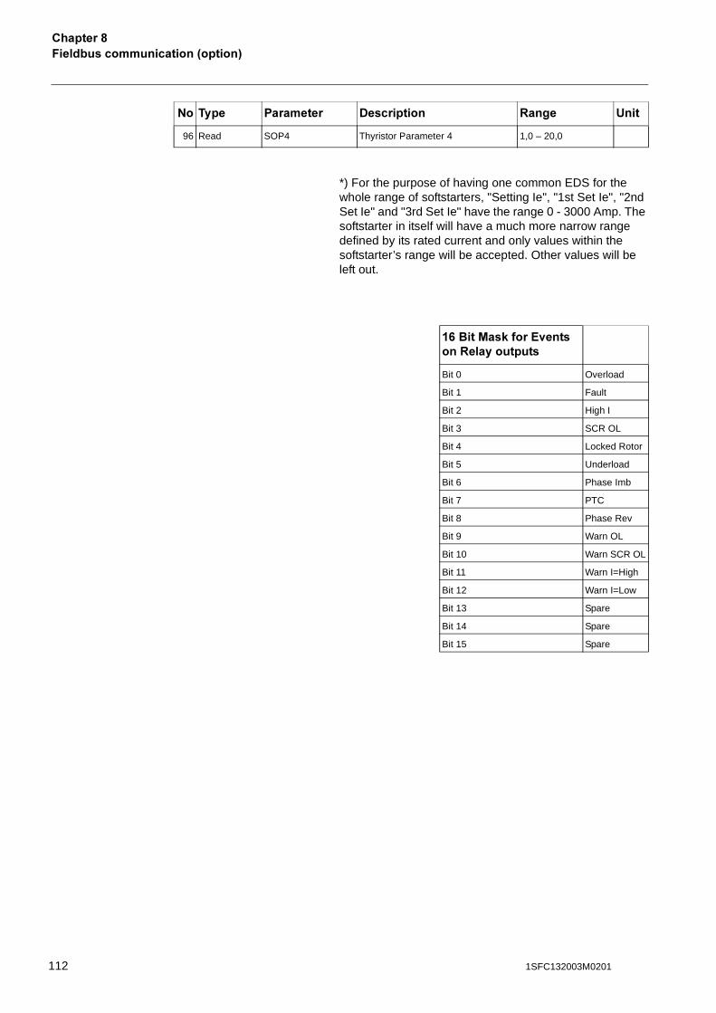
7��������������������3������4�������6
*) For the purpose of having one common EDS for the whole range of softstarters, "Setting Ie", "1st Set Ie", "2nd Set Ie" and "3rd Set Ie" have the range 0 - 3000 Amp. The softstarter in itself will have a much more narrow range defined by its rated current and only values within the softstarter’s range will be accepted. Other values will be left out.
96 Read SOP4 Thyristor Parameter 4 1,0 – 20,0
9� ��� �������� -���������� :���� &���
0���/��,���?<������:�����������
Bit 0 Overload
Bit 1 Fault
Bit 2 High I
Bit 3 SCR OL
Bit 4 Locked Rotor
Bit 5 Underload
Bit 6 Phase Imb
Bit 7 PTC
Bit 8 Phase Rev
Bit 9 Warn OL
Bit 10 Warn SCR OL
Bit 11 Warn I=High
Bit 12 Warn I=Low
Bit 13 Spare
Bit 14 Spare
Bit 15 Spare
112 1SFC132003M0201

/����������
�������5/����������
Regular maintenance ...................................................................................... 115
1131SFC132003M0201

114 1SFC132003M0201
/����������
�������5
�������5/����������
This chapter describes the maintenance required for the softstarter. In principle, the product is maintenance free but some items should be checked regularly.
�������)
������������ �������������������� �������"��������� ���� �����������������"�����������������
5� :�����������������
• Check that all mounting bolts/screws are fastened. Tighten if necessary.
• Check that all connections of main, control- and supply circuits are fastened. Tighten the terminal screws and bolts on the connection bars, if necessary.
• Check that the cooling airways are free from dirt and dust. If required, use pressurised air to clean.
• Check external filters. Clean, if necessary.• Check that the fan is working and rotating freely. The
blades shall rotate without any resistance and this can be checked at voltage free state.
• Check the real time clock and adjust if necessary.
In case of a fault or if a fault can not be reset, see Chapter 11 “Trouble shooting” .
1151SFC132003M0201

/�����������������5
116 1SFC132003M0201
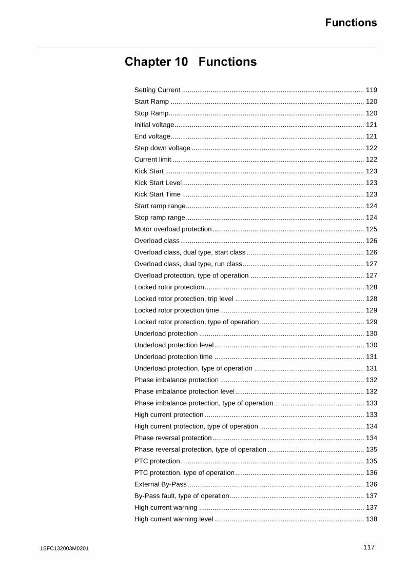
7��������
������� �7��������
Setting Current ................................................................................................ 119
Start Ramp ...................................................................................................... 120
Stop Ramp....................................................................................................... 120
Initial voltage.................................................................................................... 121
End voltage...................................................................................................... 121
Step down voltage ........................................................................................... 122
Current limit ..................................................................................................... 122
Kick Start ......................................................................................................... 123
Kick Start Level................................................................................................ 123
Kick Start Time ................................................................................................ 123
Start ramp range.............................................................................................. 124
Stop ramp range.............................................................................................. 124
Motor overload protection................................................................................ 125
Overload class................................................................................................. 126
Overload class, dual type, start class .............................................................. 126
Overload class, dual type, run class................................................................ 127
Overload protection, type of operation ............................................................ 127
Locked rotor protection.................................................................................... 128
Locked rotor protection, trip level .................................................................... 128
Locked rotor protection time ............................................................................ 129
Locked rotor protection, type of operation ....................................................... 129
Underload protection ....................................................................................... 130
Underload protection level ............................................................................... 130
Underload protection time ............................................................................... 131
Underload protection, type of operation .......................................................... 131
Phase imbalance protection ............................................................................ 132
Phase imbalance protection level .................................................................... 132
Phase imbalance protection, type of operation ............................................... 133
High current protection .................................................................................... 133
High current protection, type of operation ....................................................... 134
Phase reversal protection................................................................................ 134
Phase reversal protection, type of operation ................................................... 135
PTC protection................................................................................................. 135
PTC protection, type of operation.................................................................... 136
External By-Pass ............................................................................................. 136
By-Pass fault, type of operation....................................................................... 137
High current warning ....................................................................................... 137
High current warning level ............................................................................... 138
1171SFC132003M0201
Low current warning ........................................................................................ 138
Low current warning level ................................................................................ 138
Overload warning............................................................................................. 139
Overload warning level .................................................................................... 139
SCR overload warning..................................................................................... 139
Phase loss fault, type of operation................................................................... 140
Fieldbus fault, type of operation....................................................................... 140
Frequency fault, type of operation ................................................................... 141
Heat sink over-temperature fault, type of operation......................................... 141
Thyristor short circuit fault, type of operation................................................... 142
Programmable inputs, In0 and In1................................................................... 143
Programmable outputs, Relay K4, K5 and K6 ................................................. 144
Programmable software output V7 .................................................................. 145
Fieldbus control ............................................................................................... 146
Fieldbus type ................................................................................................... 147
Fieldbus address ............................................................................................. 147
Sequence start, number of sequences ............................................................ 148
Start ramp, first sequence................................................................................ 148
Initial voltage, first sequence ........................................................................... 149
Current limit, first sequence ............................................................................. 149
Setting current, first sequence ......................................................................... 149
Start ramp, second sequence.......................................................................... 150
Initial voltage, second sequence...................................................................... 150
Current limit, second sequence ....................................................................... 150
Setting current, second sequence ................................................................... 151
Start ramp, third sequence .............................................................................. 151
Initial voltage, third sequence .......................................................................... 151
Current limit, third sequence............................................................................ 152
Setting current, third sequence........................................................................ 152
Language......................................................................................................... 153
LCD display automatic switch-off..................................................................... 153
Password ......................................................................................................... 154
Date type ......................................................................................................... 154
Year ................................................................................................................. 155
Month............................................................................................................... 155
Day .................................................................................................................. 155
Hour ................................................................................................................. 156
Minutes ............................................................................................................ 156
118 1SFC132003M0201
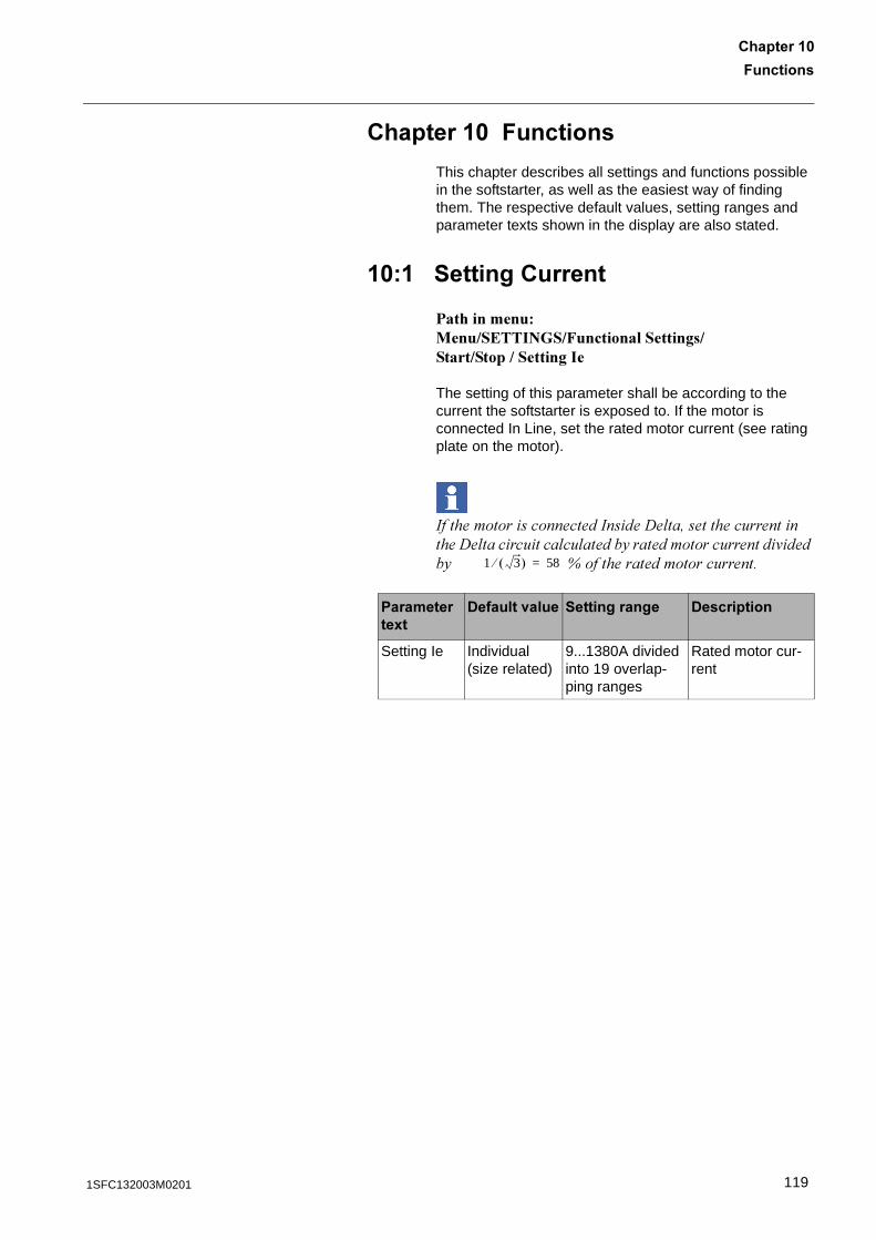
7��������
������� �
������� �7��������
This chapter describes all settings and functions possible in the softstarter, as well as the easiest way of finding them. The respective default values, setting ranges and parameter texts shown in the display are also stated.
�� ��������������
������������ ���������� ��!��������������������������������
The setting of this parameter shall be according to the current the softstarter is exposed to. If the motor is connected In Line, set the rated motor current (see rating plate on the motor).
��������������������������� ��!������������������� ��������� �� �����5������������������'����53333333333 B�����������������������
����������8�
-������<���� ������������ -����������
Setting Ie Individual (size related)
9...1380A divided into 19 overlap-ping ranges
Rated motor cur-rent
1 3� �� 58=
1191SFC132003M0201
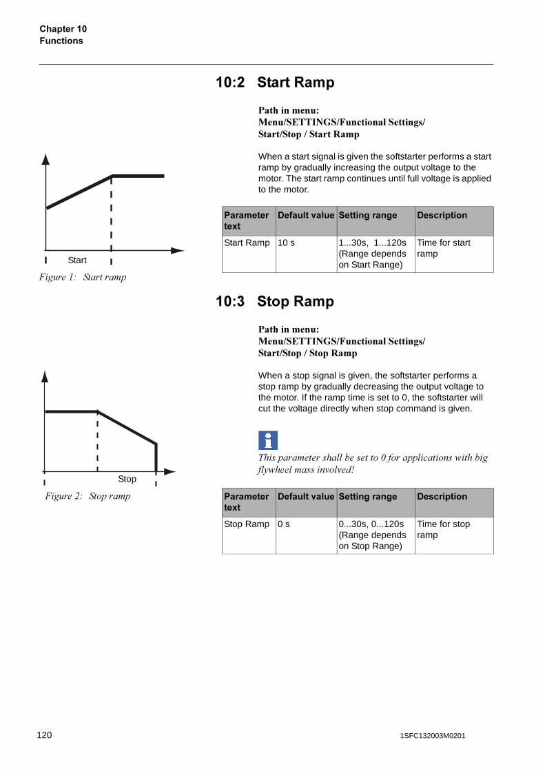
7��������������� �
��% �����:���
������������ ���������� ��!���������������������������#��
When a start signal is given the softstarter performs a start ramp by gradually increasing the output voltage to the motor. The start ramp continues until full voltage is applied to the motor.
��� ����:���
������������ ���������� ��!����������������������������#��
When a stop signal is given, the softstarter performs a stop ramp by gradually decreasing the output voltage to the motor. If the ramp time is set to 0, the softstarter will cut the voltage directly when stop command is given.
��������������� �������1������ ������ ����� 5 ��� �����'� '��G
����������8�
-������<���� ������������ -����������
Start Ramp 10 s 1...30s, 1...120s (Range depends on Start Range)
Time for start ramp
�����"# ���������
Start
����������8�
-������<���� ������������ -����������
Stop Ramp 0 s 0...30s, 0...120s (Range depends on Stop Range)
Time for stop ramp
�����$# ��������
Stop
120 1SFC132003M0201
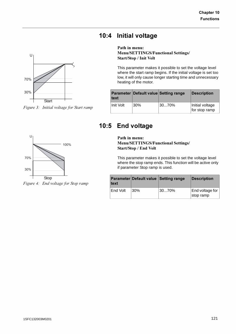
7��������
������� �
��. �������<������
������������ ���������� ��!�������������������������������
This parameter makes it possible to set the voltage level where the start ramp begins. If the initial voltage is set too low, it will only cause longer starting time and unnecessary heating of the motor.
��! ?��<������
������������ ���������� ��!��������������������������$����
This parameter makes it possible to set the voltage level where the stop ramp ends. This function will be active only if parameter Stop ramp is used.
����������8�
-������<���� ������������ -����������
Init Volt 30% 30...70% Initial voltage for stop ramp
30%
70%
U
�����&# ���� '� ����������������
Start
30%
70%
U
100%
�����(# 2��'� ���������������Stop ��������
��8�-������<���� ������������ -����������
End Volt 30% 30...70% End voltage for stop ramp
1211SFC132003M0201
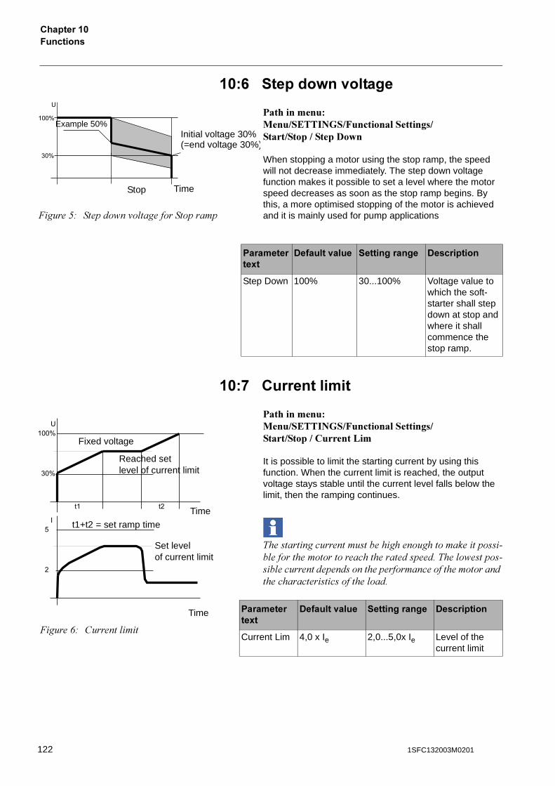
7��������������� �
��0 ������=�<������
����������� ���������� ��!����������������������������%�&�
When stopping a motor using the stop ramp, the speed will not decrease immediately. The step down voltage function makes it possible to set a level where the motor speed decreases as soon as the stop ramp begins. By this, a more optimised stopping of the motor is achieved and it is mainly used for pump applications
��* ������������
������������ ���������� ��!�������������������������������'��
It is possible to limit the starting current by using this function. When the current limit is reached, the output voltage stays stable until the current level falls below the limit, then the ramping continues.
��������������������������������������������� ������������������������������������ � ��������� ����������������������������������������������������������������� ����
����������8�
-������<���� ������������ -����������
Step Down 100% 30...100% Voltage value to which the soft-starter shall step down at stop and where it shall commence the stop ramp.
�����*# ������ �'� ���������������
Example 50%
Stop Time
Initial voltage 30%(=end voltage 30%)
����������8�
-������<���� ������������ -����������
Current Lim 4,0 x Ie 2,0...5,0x Ie Level of the current limit
�����+# ������� ��
�3���Fixed voltage
Reached set level of current limit
t1+t2 = set ramp time
Set level of current limit
Time
Time
122 1SFC132003M0201
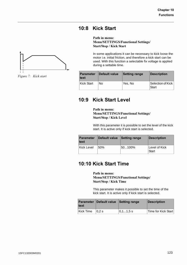
7��������
������� �
��6 A��,�����
������������ ���������� ��!������������������������(��)���
In some applications it can be necessary to kick loose the motor i.e. initial friction, and therefore a kick start can be used. With this function a selectable fix voltage is applied during a settable time.
��5 A��,�����B�<��
������������ ���������� ��!������������������������(��)�'�*��
With this parameter it is possible to set the level of the kick start. It is active only if kick start is selected.
�� � A��,��������
������������ ���������� ��!������������������������(��)�����
This parameter makes it possible to set the time of the kick start. It is active only if kick start is selected.
�����,# @������� ����������8�
-������<���� ������������ -����������
Kick Start No Yes, No Selection of Kick Start
����������8�
-������<���� ������������ -����������
Kick Level 50% 50...100% Level of Kick Start
����������8�
-������<���� ������������ -����������
Kick Time 0,2 s 0,1...1,5 s Time for Kick Start
1231SFC132003M0201
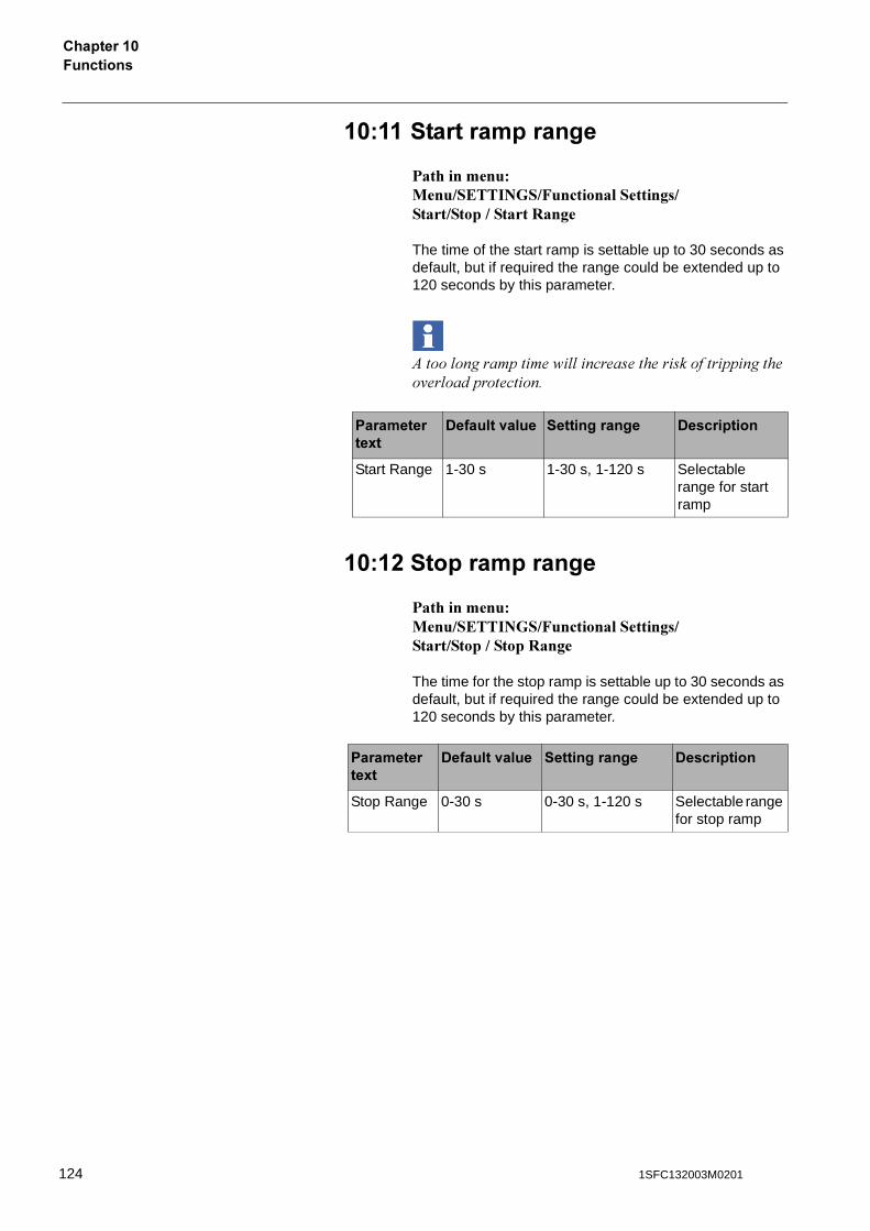
7��������������� �
�� ��������������
������������ ���������� ��!���������������������������#���
The time of the start ramp is settable up to 30 seconds as default, but if required the range could be extended up to 120 seconds by this parameter.
)��� ���������� �������������������������'�� �������������
�� % �������������
������������ ���������� ��!����������������������������#���
The time for the stop ramp is settable up to 30 seconds as default, but if required the range could be extended up to 120 seconds by this parameter.
����������8�
-������<���� ������������ -����������
Start Range 1-30 s 1-30 s, 1-120 s Selectable range for start ramp
����������8�
-������<���� ������������ -����������
Stop Range 0-30 s 0-30 s, 1-120 s Selectable range for stop ramp
124 1SFC132003M0201
7��������
������� �
�� � /�����<����������������
������������ ���������� ��!�������������������������+*����$
This parameter makes it possible to set the required function of the integrated motor overload protection. Too high motor temperature causes a stop of the motor and a reset is necessary before a restart is possible. The motor overload protection has three different modes:
������������������� ���������������������� ������������� �� ����
9� The protection is not activated.
9����� The protection is in normal operation.
-��� The protection has two classes, one during start and another during continuous run.
����������8�
-������<���� ������������ -����������
Overload Normal No, Normal, Dual Overload protec-tion
1251SFC132003M0201
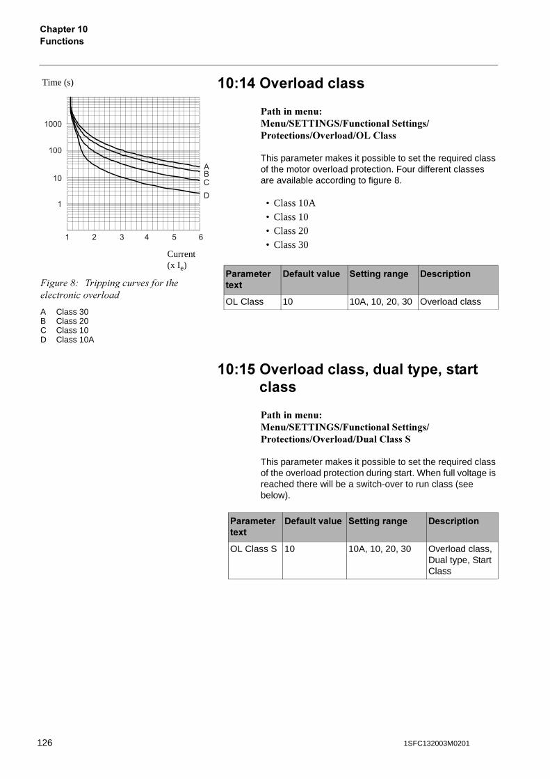
7��������������� �
�� . ><�����������
������������ ���������� ��!�������������������������+*����$�+'�����
This parameter makes it possible to set the required class of the motor overload protection. Four different classes are available according to figure 8.
• Class 10A• Class 10• Class 20• Class 30
�� ! ><�����������'��������'����������
������������ ���������� ��!�������������������������+*����$�%���������
This parameter makes it possible to set the required class of the overload protection during start. When full voltage is reached there will be a switch-over to run class (see below).
����������8�
-������<���� ������������ -����������
OL Class 10 10A, 10, 20, 30 Overload class
1
10
100
1000
1
2 3 4 5 6
ABCD
Time (s)
�����-# ���������'��������� ��������'�� ���
A Class 30B Class 20C Class 10D Class 10A
Current (x Ie)
����������8�
-������<���� ������������ -����������
OL Class S 10 10A, 10, 20, 30 Overload class, Dual type, Start Class
126 1SFC132003M0201
7��������
������� �
�� 0 ><�����������'��������'��������
������������ ���������� ��!�������������������������+*����$�%��������#
This parameter makes it possible to set the required class of the overload protection for continuous run. The run class is activated 30 seconds after full voltage has been reached.
�� * ><����������������'���������������
������������ ���������� ��!�������������������������+*����$�+'�+�
This parameter makes it possible to select between three different actions by the softstarter when the protection is activated. It is active only if the motor overload protection is selected.
����������8�
-������<���� ������������ -����������
OL Class R 10 10A, 10, 20, 30 Overload class, Dual type, Run Class
Stop–M The motor stops and a manual reset is required before restart.
Stop–A The motor stops and an automatic reset is performed when the fault disappears
Ind The motor continues to run but a fault indi-cation is given.
����������8�
-������<���� ������������ -����������
OL Op Stop–M Stop–M, Stop–A, Ind
Type of opera-tion for over-load protection
1271SFC132003M0201

7��������������� �
�� 6 B��,�����������������
������������ ���������� ��!�������������������������'��)�$�#���
If the motor current exceeds the set level and the set time when the motor is running at full voltage, this protection is activated. The protection starts monitoring when full voltage is applied to the motor.
�� 5 B��,�����������������'������<��
������������ ���������� ��!�������������������������'��)�$�#����'��)�#�'�*
This function makes it possible to set the level of the locked rotor protection. It is active only if Locked rotor protection is selected.
����������8�
-������<���� ������������ -����������
Locked Rotor
No Yes, No Locked rotor protection
����������8�
-������<���� ������������ -����������
Lock R Lev 4,0 x Ie 3,0...8,0 x Ie Trip level for locked rotor protection
128 1SFC132003M0201
7��������
������� �
��%� B��,���������������������
������������ ���������� ��!�������������������������'��)�$�#����'��)�#�����
This parameter makes it possible to set the delay time from detection until activation of the protection.It is active only if Locked rotor protection is selected.
��% B��,�����������������'���������������
������������ ���������� ��!�������������������������'��)�$�#����'��)�#�+�
This parameter makes it possible to select between three different actions of the softstarter when the protection is activated. It is active only if the Locked rotor protection is selected.
����������8�
-������<���� ������������ -����������
Lock R Time
1,0 s 0,2...10,0 s Trip time for locked rotor pro-tection
Stop–M The motor stops and a manual reset is required before restart.
Stop–Ind The motor stops and an automatic reset is performed when the fault disappears
Ind The motor continues to run but a fault indi-cation is given.
����������8�
-������<���� ������������ -����������
Lock R Op Stop–M Stop–M, Stop–A, Ind
Type of opera-tion for locked rotor protection
1291SFC132003M0201
7��������������� �
��%% &������������������
������������ ���������� ��!�������������������������,�$����$
If the motor current falls below the set level and the set time when the motor is running at full voltage, the protection is activated. The protection starts monitoring when full voltage is applied to the motor.
��������������� ����������'������3��� ��������������5!��������������� ����� ���
��%� &��������������������<��
������������ ���������� ��!�������������������������,�$����$�,�$����'�*
This parameter makes it possible to set the level of the underload protection. It is active only if the underload protection is selected.
����������8�
-������<���� ������������ -����������
Underload No Yes, No Underload pro-tection
����������8�
-������<���� ������������ -����������
Underl Lev 0,8 x Ie 0,4...0,8 x Ie Trip level for Underload pro-tection
130 1SFC132003M0201
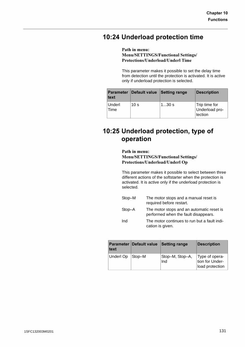
7��������
������� �
��%. &����������������������
������������ ���������� ��!�������������������������,�$����$�,�$��������
This parameter makes it possible to set the delay time from detection until the protection is activated. It is active only if underload protection is selected.
��%! &������������������'���������������
������������ ���������� ��!�������������������������,�$����$�,�$����+�
This parameter makes it possible to select between three different actions of the softstarter when the protection is activated. It is active only if the underload protection is selected.
����������8�
-������<���� ������������ -����������
Underl Time
10 s 1...30 s Trip time for Underload pro-tection
Stop–M The motor stops and a manual reset is required before restart.
Stop–A The motor stops and an automatic reset is performed when the fault disappears.
Ind The motor continues to run but a fault indi-cation is given.
����������8�
-������<���� ������������ -����������
Underl Op Stop–M Stop–M, Stop–A, Ind
Type of opera-tion for Under-load protection
1311SFC132003M0201
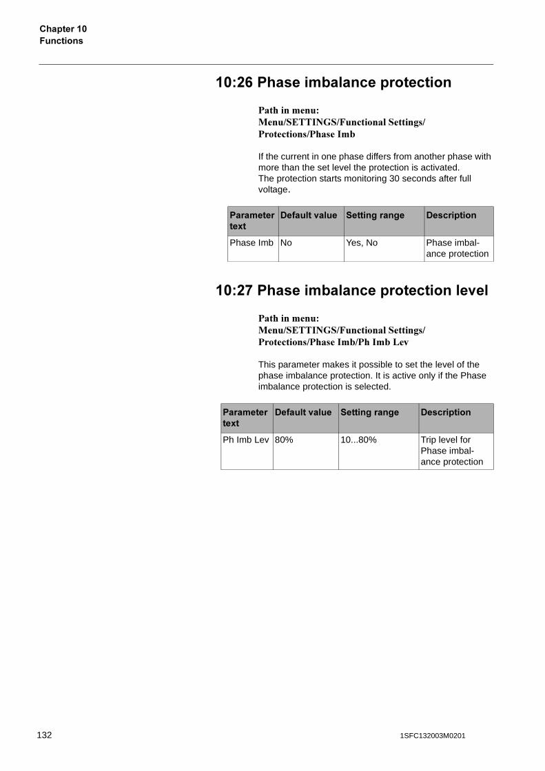
7��������������� �
��%0 �����������������������
������������ ���������� ��!��������������������������������-
If the current in one phase differs from another phase with more than the set level the protection is activated.The protection starts monitoring 30 seconds after full voltage.
��%* �������������������������<��
������������ ���������� ��!��������������������������������-������-�'�*
This parameter makes it possible to set the level of the phase imbalance protection. It is active only if the Phase imbalance protection is selected.
����������8�
-������<���� ������������ -����������
Phase Imb No Yes, No Phase imbal-ance protection
����������8�
-������<���� ������������ -����������
Ph Imb Lev 80% 10...80% Trip level for Phase imbal-ance protection
132 1SFC132003M0201
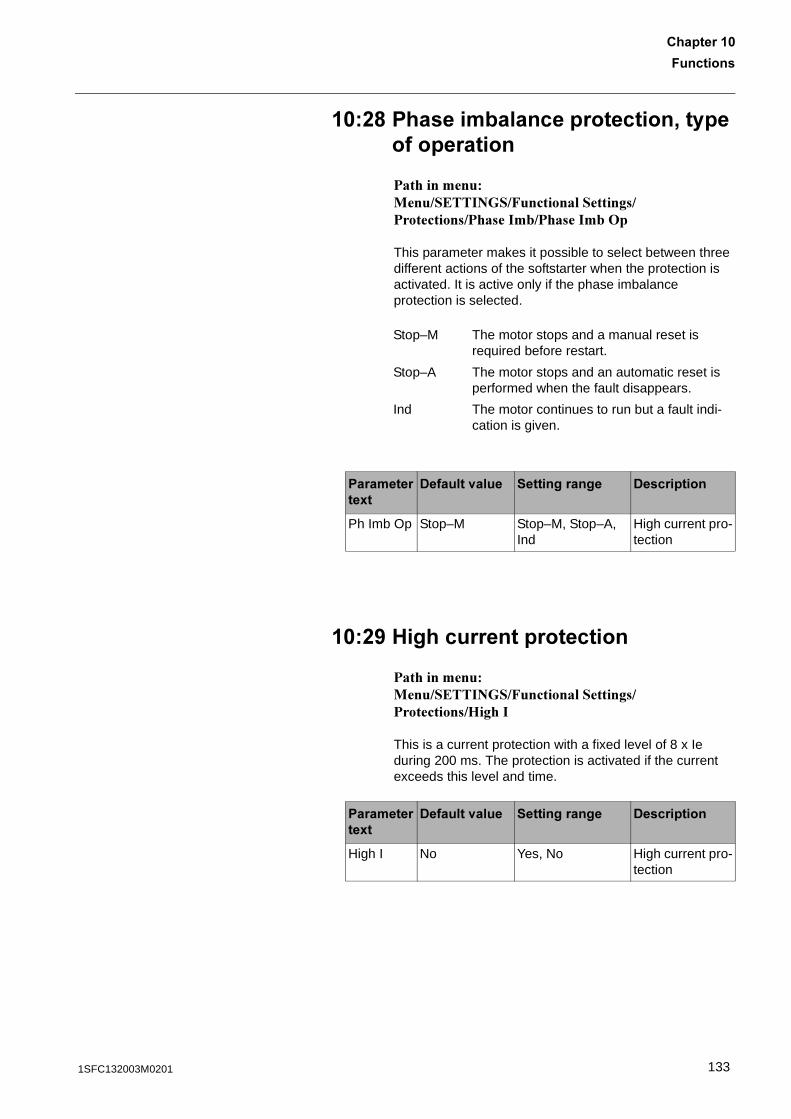
7��������
������� �
��%6 �����������������������'���������������
������������ ���������� ��!��������������������������������-��������-�+�
This parameter makes it possible to select between three different actions of the softstarter when the protection is activated. It is active only if the phase imbalance protection is selected.
��%5 1��������������������
������������ ���������� ��!�������������������������.�����
This is a current protection with a fixed level of 8 x Ie during 200 ms. The protection is activated if the current exceeds this level and time.
Stop–M The motor stops and a manual reset is required before restart.
Stop–A The motor stops and an automatic reset is performed when the fault disappears.
Ind The motor continues to run but a fault indi-cation is given.
����������8�
-������<���� ������������ -����������
Ph Imb Op Stop–M Stop–M, Stop–A, Ind
High current pro-tection
����������8�
-������<���� ������������ -����������
High I No Yes, No High current pro-tection
1331SFC132003M0201
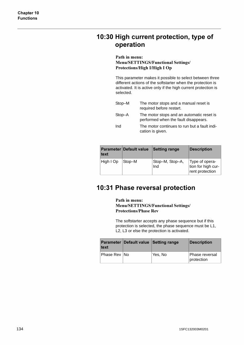
7��������������� �
���� 1��������������������'���������������
������������ ���������� ��!�������������������������.������.������+�
This parameter makes it possible to select between three different actions of the softstarter when the protection is activated. It is active only if the high current protection is selected.
��� ������<���������������
������������ ���������� ��!������������������������������#�*
The softstarter accepts any phase sequence but if this protection is selected, the phase sequence must be L1, L2, L3 or else the protection is activated.
Stop–M The motor stops and a manual reset is required before restart.
Stop–A The motor stops and an automatic reset is performed when the fault disappears.
Ind The motor continues to run but a fault indi-cation is given.
����������8�
-������<���� ������������ -����������
High I Op Stop–M Stop–M, Stop–A, Ind
Type of opera-tion for high cur-rent protection
����������8�
-������<���� ������������ -����������
Phase Rev No Yes, No Phase reversal protection
134 1SFC132003M0201
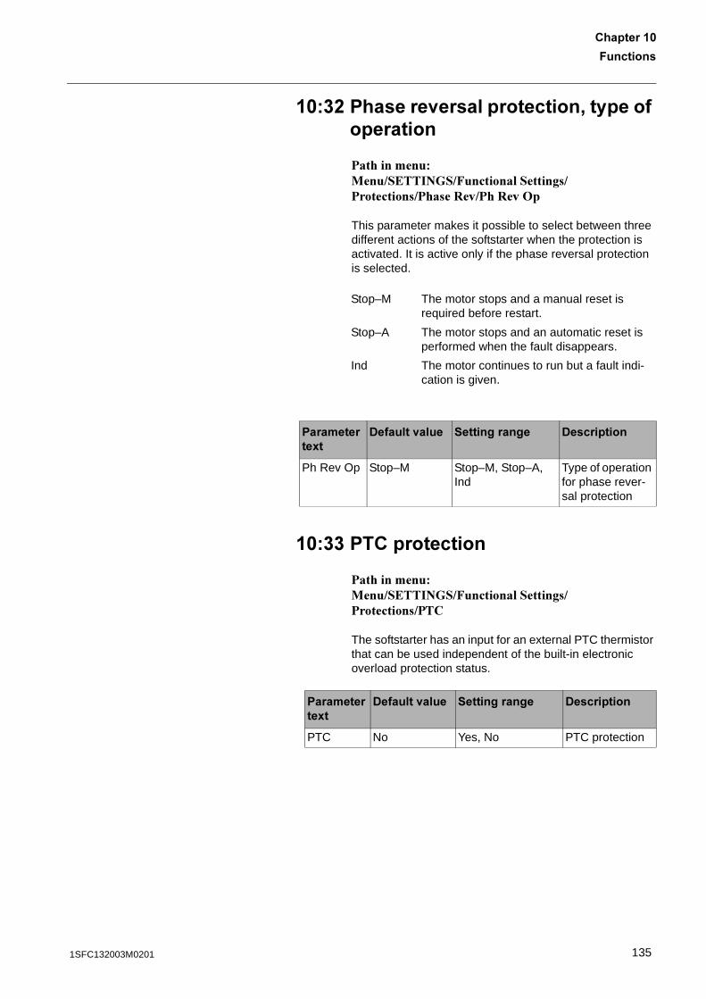
7��������
������� �
���% ������<���������������'���������������
������������ ���������� ��!������������������������������#�*����#�*�+�
This parameter makes it possible to select between three different actions of the softstarter when the protection is activated. It is active only if the phase reversal protection is selected.
���� �����������
������������ ���������� ��!����������������������������
The softstarter has an input for an external PTC thermistor that can be used independent of the built-in electronic overload protection status.
Stop–M The motor stops and a manual reset is required before restart.
Stop–A The motor stops and an automatic reset is performed when the fault disappears.
Ind The motor continues to run but a fault indi-cation is given.
����������8�
-������<���� ������������ -����������
Ph Rev Op Stop–M Stop–M, Stop–A, Ind
Type of operation for phase rever-sal protection
����������8�
-������<���� ������������ -����������
PTC No Yes, No PTC protection
1351SFC132003M0201
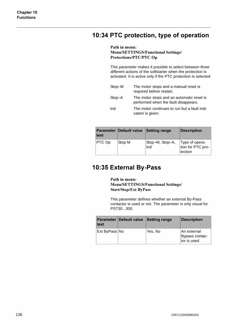
7��������������� �
���. �����������'���������������
������������ ���������� ��!���������������������������������+�
This parameter makes it possible to select between three different actions of the softstarter when the protection is activated. It is active only if the PTC protection is selected
���! ?8��������2 ���
������������ ���������� ��!�����������������������/������
This parameter defines whether an external By-Pass contactor is used or not. The parameter is only visual for PST30...300.
Stop–M The motor stops and a manual reset is required before restart.
Stop–A The motor stops and an automatic reset is performed when the fault disappears.
Ind The motor continues to run but a fault indi-cation is given.
����������8�
-������<���� ������������ -����������
PTC Op Stop M Stop–M, Stop–A, Ind
Type of opera-tion for PTC pro-tection
����������8�
-������<���� ������������ -����������
Ext ByPass No Yes, No An external Bypass contac-tor is used
136 1SFC132003M0201
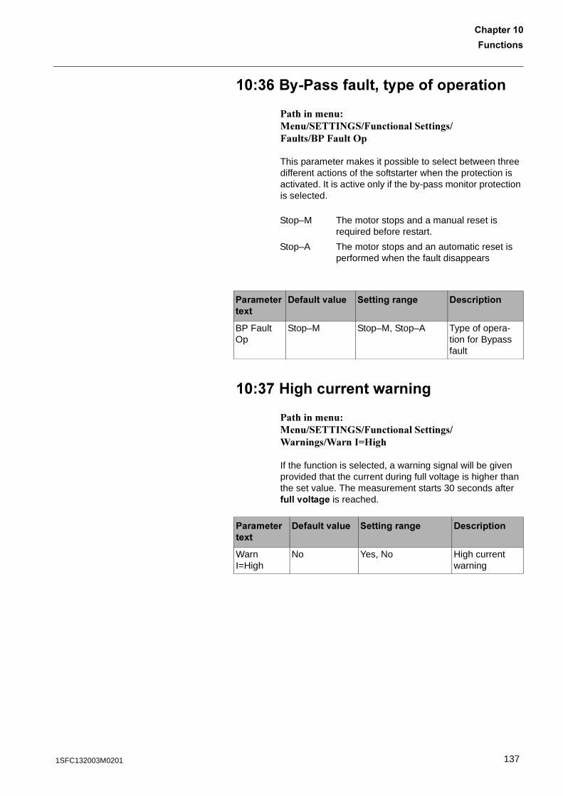
7��������
������� �
���0 ��2 ��������'���������������
������������ ���������� ��!���������������!�������!���+�
This parameter makes it possible to select between three different actions of the softstarter when the protection is activated. It is active only if the by-pass monitor protection is selected.
���* 1����������=������
������������ ���������� ��!���������������0�������0����1.���
If the function is selected, a warning signal will be given provided that the current during full voltage is higher than the set value. The measurement starts 30 seconds after ����<������ is reached.
Stop–M The motor stops and a manual reset is required before restart.
Stop–A The motor stops and an automatic reset is performed when the fault disappears
����������8�
-������<���� ������������ -����������
BP Fault Op
Stop–M Stop–M, Stop–A Type of opera-tion for Bypass fault
����������8�
-������<���� ������������ -����������
Warn I=High
No Yes, No High current warning
1371SFC132003M0201
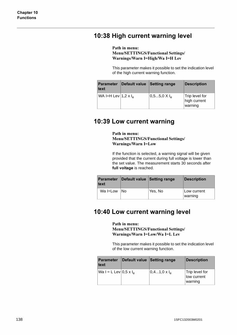
7��������������� �
���6 1����������=��������<��
������������ ���������� ��!���������������0�������0����1.����0��1.�'�*
This parameter makes it possible to set the indication level of the high current warning function.
���5 B�=�������=������
������������ ���������� ��!���������������0�������0����1'�&
If the function is selected, a warning signal will be given provided that the current during full voltage is lower than the set value. The measurement starts 30 seconds after ����<������ is reached.
��.� B�=�������=��������<��
������������ ���������� ��!���������������0�������0����1'�&�0��1'�'�*
This parameter makes it possible to set the indication level of the low current warning function.
����������8�
-������<���� ������������ -����������
WA I=H Lev 1,2 x Ie 0,5...5,0 X Ie Trip level for high current warning
����������8�
-������<���� ������������ -����������
Wa I=Low No Yes, No Low current warning
����������8�
-������<���� ������������ -����������
Wa I = L Lev 0,5 x Ie 0,4...1,0 x Ie Trip level for low current warning
138 1SFC132003M0201
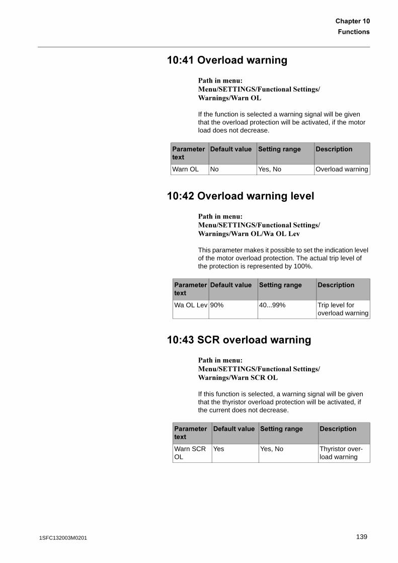
7��������
������� �
��. ><������=������
������������ ���������� ��!���������������0�������0���+'
If the function is selected a warning signal will be given that the overload protection will be activated, if the motor load does not decrease.
��.% ><������=��������<��
������������ ���������� ��!���������������0�������0���+'�0�+'�'�*
This parameter makes it possible to set the indication level of the motor overload protection. The actual trip level of the protection is represented by 100%.
��.� ��:�<������=������
������������ ���������� ��!���������������0�������0�����#�+'
If this function is selected, a warning signal will be given that the thyristor overload protection will be activated, if the current does not decrease.
����������8�
-������<���� ������������ -����������
Warn OL No Yes, No Overload warning
����������8�
-������<���� ������������ -����������
Wa OL Lev 90% 40...99% Trip level for overload warning
����������8�
-������<���� ������������ -����������
Warn SCR OL
Yes Yes, No Thyristor over-load warning
1391SFC132003M0201
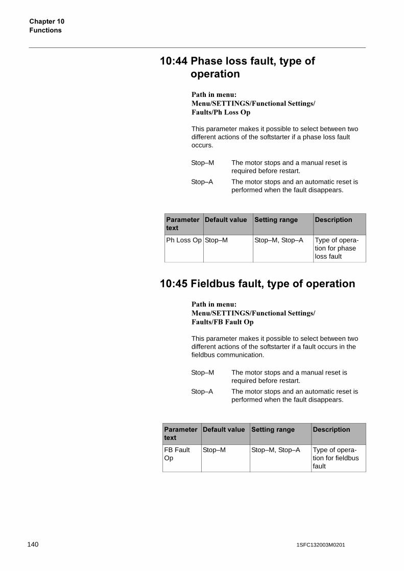
7��������������� �
��.. �������������'���������������
������������ ���������� ��!���������������!�������'����+�
This parameter makes it possible to select between two different actions of the softstarter if a phase loss fault occurs.
��.! 7������������'���������������
������������ ���������� ��!���������������!����!��!���+�
This parameter makes it possible to select between two different actions of the softstarter if a fault occurs in the fieldbus communication.
Stop–M The motor stops and a manual reset is required before restart.
Stop–A The motor stops and an automatic reset is performed when the fault disappears.
����������8�
-������<���� ������������ -����������
Ph Loss Op Stop–M Stop–M, Stop–A Type of opera-tion for phase loss fault
Stop–M The motor stops and a manual reset is required before restart.
Stop–A The motor stops and an automatic reset is performed when the fault disappears.
����������8�
-������<���� ������������ -����������
FB Fault Op
Stop–M Stop–M, Stop–A Type of opera-tion for fieldbus fault
140 1SFC132003M0201
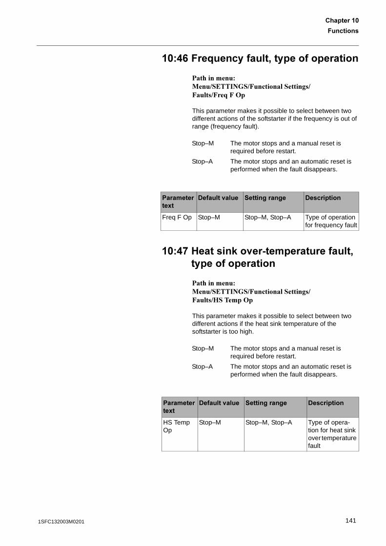
7��������
������� �
��.0 7��;����������'���������������
������������ ���������� ��!���������������!����!��2�!�+�
This parameter makes it possible to select between two different actions of the softstarter if the frequency is out of range (frequency fault).
��.* 1������,�<��2����������������'���������������
������������ ���������� ��!���������������!����.�������+�
This parameter makes it possible to select between two different actions if the heat sink temperature of the softstarter is too high.
Stop–M The motor stops and a manual reset is required before restart.
Stop–A The motor stops and an automatic reset is performed when the fault disappears.
����������8�
-������<���� ������������ -����������
Freq F Op Stop–M Stop–M, Stop–A Type of operation for frequency fault
Stop–M The motor stops and a manual reset is required before restart.
Stop–A The motor stops and an automatic reset is performed when the fault disappears.
����������8�
-������<���� ������������ -����������
HS Temp Op
Stop–M Stop–M, Stop–A Type of opera-tion for heat sink over temperature fault
1411SFC132003M0201
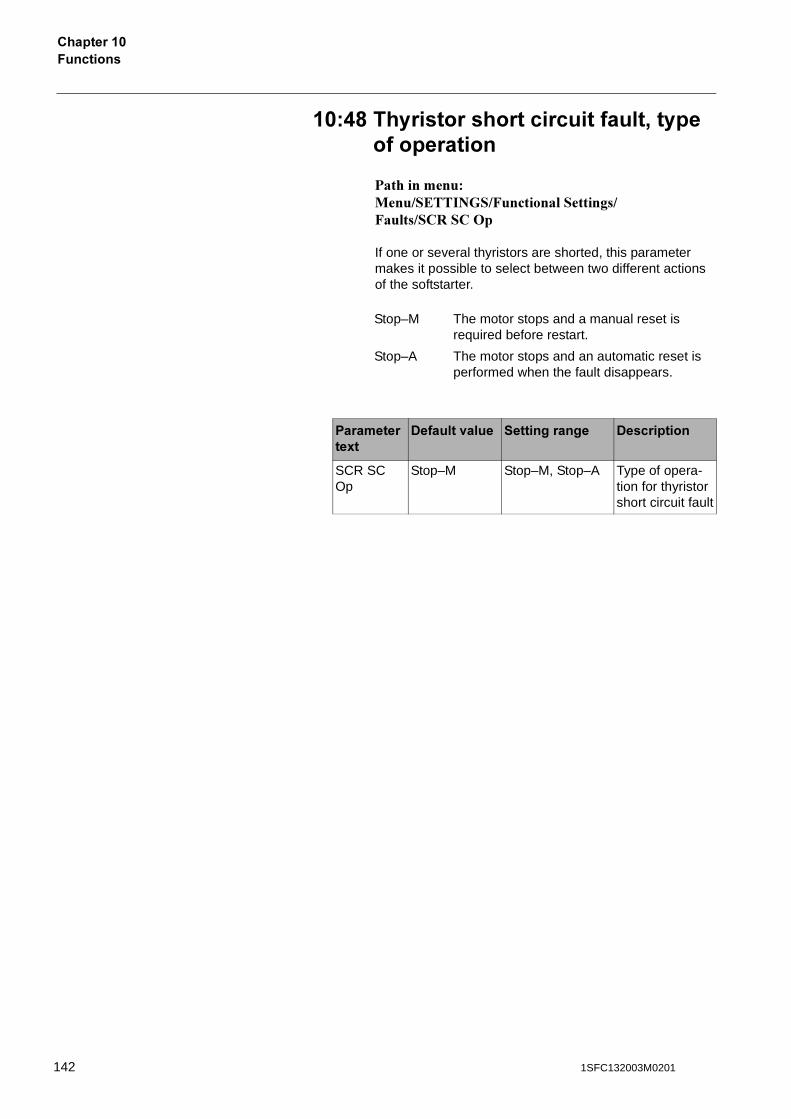
7��������������� �
��.6 �������������������������'���������������
������������ ���������� ��!���������������!������#����+�
If one or several thyristors are shorted, this parameter makes it possible to select between two different actions of the softstarter.
Stop–M The motor stops and a manual reset is required before restart.
Stop–A The motor stops and an automatic reset is performed when the fault disappears.
����������8�
-������<���� ������������ -����������
SCR SC Op
Stop–M Stop–M, Stop–A Type of opera-tion for thyristor short circuit fault
142 1SFC132003M0201
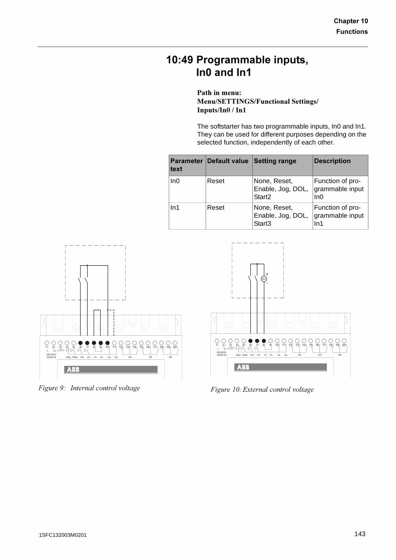
7��������
������� �
��.5 �����������������'��������
������������ ���������� ��!�����������������������3�����4
The softstarter has two programmable inputs, In0 and In1. They can be used for different purposes depending on the selected function, independently of each other.
����������8�
-������<���� ������������ -����������
In0 Reset None, Reset, Enable, Jog, DOL, Start2
Function of pro-grammable input In0
In1 Reset None, Reset, Enable, Jog, DOL, Start3
Function of pro-grammable input In1
1 2 3 4 5 6 7 8 9 10 11 12 13 14 15 16 17 18 19 20
100-250VL N
Stop Start In1 Vc Vn Vp Vp K4 In050/60 Hz K5 K6
�����.# ������� ������ '� ����
DC+
-
1 2 3 4 5 6 7 8 9 10 11 12 13 14 15 16 17 18 19 20
100-250VL N
Stop Start In1 Vc Vn Vp Vp K4 In050/60 Hz K5 K6
�����"1#23����� ������ '� ����
1431SFC132003M0201

7��������������� �
��!� ������������������':����A.'A!���A0
����������� ���������� ��!���������������+�����#����(5���(6���(7
�=�����<��������
The softstarter has three programmable output relays that can be used for different purposes depending on the selected function, independently of each other.Relay K4 has default setting Run, relay K5 has default setting Top of Ramp and relay K6 has default setting Event.
Run signal is given during start ramp, running, and stop ramp if used.
Top of Ramp signal is given when full voltage to the motor is applied.
The event function has several alternatives that can be switched On/Off as required.
One, several or all indications can be used individually, independently of each other at the same time for each output relay.
• Motor Overload Protection• Fault• High Current Protection• SCR Overload Protection• Locked Rotor Protection• Underload Protection• Phase Imbalance Protection• PTC Protection• Phase Reversal Protection• Overload Warning• SCR Overload Warning• High current warning• Low current warning
144 1SFC132003M0201
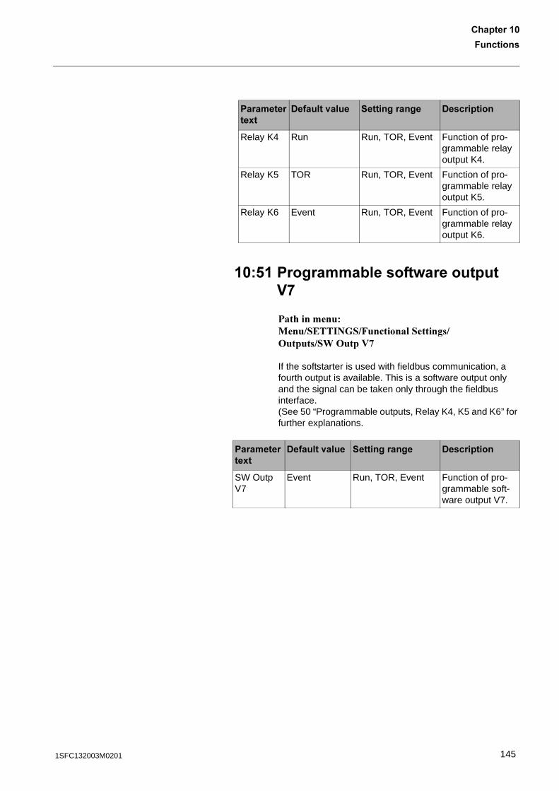
7��������
������� �
��! ���������������=���������D*
����������� ���������� ��!���������������+������0�+����8
If the softstarter is used with fieldbus communication, a fourth output is available. This is a software output only and the signal can be taken only through the fieldbus interface.(See 50 “Programmable outputs, Relay K4, K5 and K6” for further explanations.
����������8�
-������<���� ������������ -����������
Relay K4 Run Run, TOR, Event Function of pro-grammable relay output K4.
Relay K5 TOR Run, TOR, Event Function of pro-grammable relay output K5.
Relay K6 Event Run, TOR, Event Function of pro-grammable relay output K6.
����������8�
-������<���� ������������ -����������
SW Outp V7
Event Run, TOR, Event Function of pro-grammable soft-ware output V7.
1451SFC132003M0201
7��������������� �
��!% 7��������������
����������� ���������� ��!���������������!���$-���!���$-����
If the softstarter is going to be used with fieldbus communication, the fieldbus interface must be activated before any action can be taken.
(������)
)��� ����������������������� ������������/������������� ����������0�����1����� �������������� ��������2����������������"�������� ���������������������3�)��� ��������������������������� ������������/������������� ����������1������0���� ������ ��������� ������������ ���������������������������������� ����������������������
����������8�
-������<���� ������������ -����������
Fieldb Ctrl No Yes, No Control of the softstarter with fieldbus.
146 1SFC132003M0201
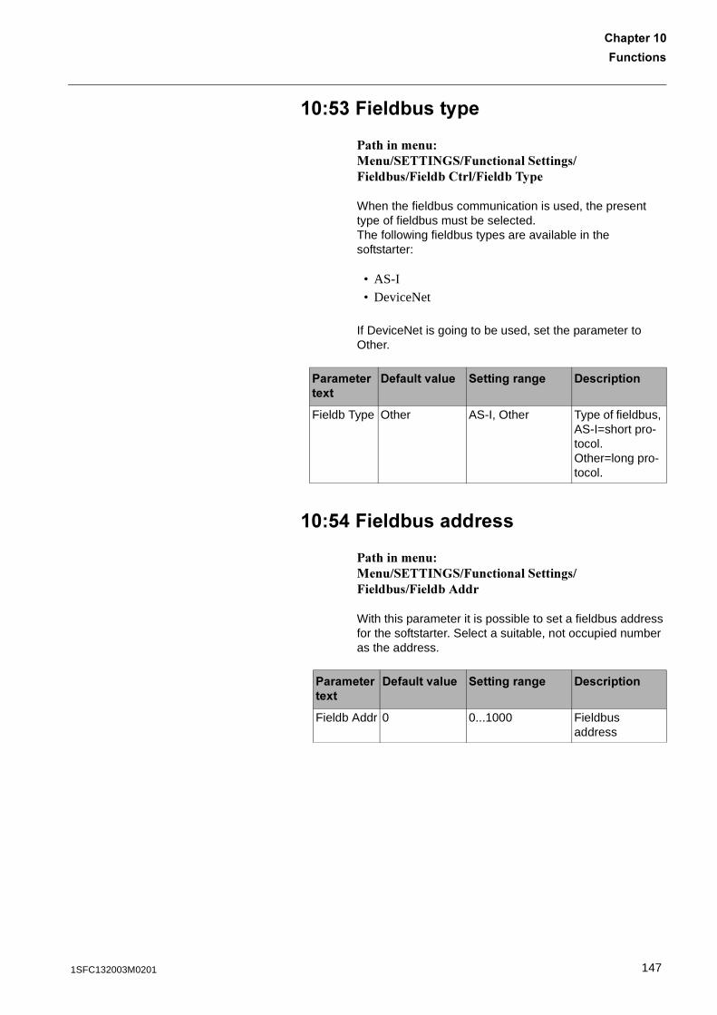
7��������
������� �
��!� 7�����������
����������� ���������� ��!���������������!���$-���!���$-�����!���$-�����
When the fieldbus communication is used, the present type of fieldbus must be selected.The following fieldbus types are available in the softstarter:
• AS-I• DeviceNet
If DeviceNet is going to be used, set the parameter to Other.
��!. 7��������������
����������� ���������� ��!���������������!���$-���!���$-�9$$�
With this parameter it is possible to set a fieldbus address for the softstarter. Select a suitable, not occupied number as the address.
����������8�
-������<���� ������������ -����������
Fieldb Type Other AS-I, Other Type of fieldbus, AS-I=short pro-tocol.Other=long pro-tocol.
����������8�
-������<���� ������������ -����������
Fieldb Addr 0 0...1000 Fieldbus address
1471SFC132003M0201
7��������������� �
��!! ��;����������'����������;������
����������� ���������� ��!�����������������2������������2
The softstarter can start motors with up to three different parameter sets (1st parameter set, 2nd parameter set and 3rd parameter set). This function can be used for starting motors in a sequence (one by one) and also for starting two or three speed motors where different starting parameters are required for each speed.
���0/�)0�/=�6/0����������������������;������������� ������
��!0 ���������'�������;�����
����������� ���������� ��!�����������������2����4����2"����"����#��4
This parameter makes it possible to set the start ramp time for the first parameter set.
����������8�
-������<���� ������������ -����������
No of Seq No No, 2, 3 Number of sequences for sequence start.
����������8�
-������<���� ������������ -����������
Start Ramp1
10 s 1...30s, 1...120s First sequence, time for start ramp
148 1SFC132003M0201
7��������
������� �
��!* �������<������'�������;�����
����������� ���������� ��!�����������������2����4����2"����"��������4
This parameter makes it possible to set the initial voltage for the first parameter set.
��!6 ������������'�������;�����
����������� ���������� ��!�����������������2����4����2"����"������'��4
This parameter makes it possible to set the current limit level for the first parameter set.
��!5 ��������������'�������;�����
����������� ���������� ��!�����������������2����4����2"����"�4�������
This parameter makes it possible to set the rated motor current for the first parameter set.
����������8�
-������<���� ������������ -����������
Init Volt1 30% 30...70% First sequence, initial voltage for start ramp
����������8�
-������<���� ������������ -����������
Curr Lim1 4 x Ie 2,0...5,0 x Ie First sequence, current limit
����������8�
-������<���� ������������ -����������
1st Set Ie Ir 9...1380A divided into 19 overlap-ping ranges
First sequence, motor rated cur-rent
1491SFC132003M0201
7��������������� �
��0� ���������'��������;�����
����������� ���������� ��!�����������������2����:�$���2"����"����#��:
This parameter makes it possible to set the start ramp time for the second parameter set.
��0 �������<������'��������;�����
����������� ���������� ��!�����������������2����:�$���2"����"��������:
This parameter makes it possible to set the initial voltage for the second parameter set.
��0% ������������'��������;�����
����������� ���������� ��!�����������������2����:�$���2"����"������'��:
This parameter makes it possible to set the current limit level for the second parameter set.
����������8�
-������<���� ������������ -����������
Start Ramp2
10 s 1...30s, 1...120s Second sequence, time for start ramp
����������8�
-������<���� ������������ -����������
Init Volt2 30% 30...70% Second sequence, ini-tial voltage for start ramp
����������8�
-������<���� ������������ -����������
Curr Lim2 4 x Ie 2,0...5,0 x Ie Second sequence, cur-rent limit
150 1SFC132003M0201
7��������
������� �
��0� ��������������'��������;�����
����������� ���������� ��!�����������������2����:�$���2"����"�:�$������
This parameter makes it possible to set the rated motor current for the second parameter set.
��0. ���������'�������;�����
����������� ���������� ��!�����������������2����;�$���2"����"����#��;
This parameter makes it possible to set the start ramp time for the third parameter set.
��0! �������<������'�������;�����
����������� ���������� ��!�����������������2����;�$���2"����"��������;
This parameter makes it possible to set the initial voltage for the third parameter set.
����������8�
-������<���� ������������ -����������
2nd Set Ie Ir 9...1380A divided into 19 overlap-ping ranges
Second sequence, motor rated current
����������8�
-������<���� ������������ -����������
Start Ramp3
10 s 1...30s, 1...120s Third sequence, time for start ramp
����������8�
-������<���� ������������ -����������
Init Volt3 30% 30...70% Third sequence, initial voltage for start ramp
1511SFC132003M0201
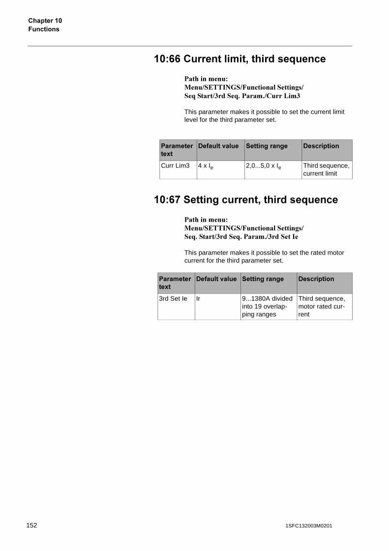
7��������������� �
��00 ������������'�������;�����
����������� ���������� ��!�����������������2����;�$���2"����"������'��;
This parameter makes it possible to set the current limit level for the third parameter set.
��0* ��������������'�������;�����
����������� ���������� ��!�����������������2"����;�$���2"����"�;�$������
This parameter makes it possible to set the rated motor current for the third parameter set.
����������8�
-������<���� ������������ -����������
Curr Lim3 4 x Ie 2,0...5,0 x Ie Third sequence, current limit
����������8�
-������<���� ������������ -����������
3rd Set Ie Ir 9...1380A divided into 19 overlap-ping ranges
Third sequence, motor rated cur-rent
152 1SFC132003M0201

7��������
������� �
��06 B�������
������������ ���������� ��������������"�'�����
The text on the LCD display can be presented in 10 different languages. This parameter makes it possible to select among the following languages:
• English• Chinese• German• Spanish• French• Italian• Dutch• Portuguese• Swedish• Finnish
��05 B�-�����������������=����2���
������������ ���������� ��������������"�'�%�9���+��
The LCD display on the softstarter will be automatically switched off by a pre-set time. This time is always calculated from the last key pressureWith this parameter it is possible to set this time .
����������8�
-������<���� ������������ -����������
Language US/UK US/UK, CN, DE, ES, FR, IT, NL, PT, SE, FI
Language to use on display
����������8�
-������<���� ������������ -����������
LCD Auto Off
15 1...255 min Time for display automatic turn off
1531SFC132003M0201
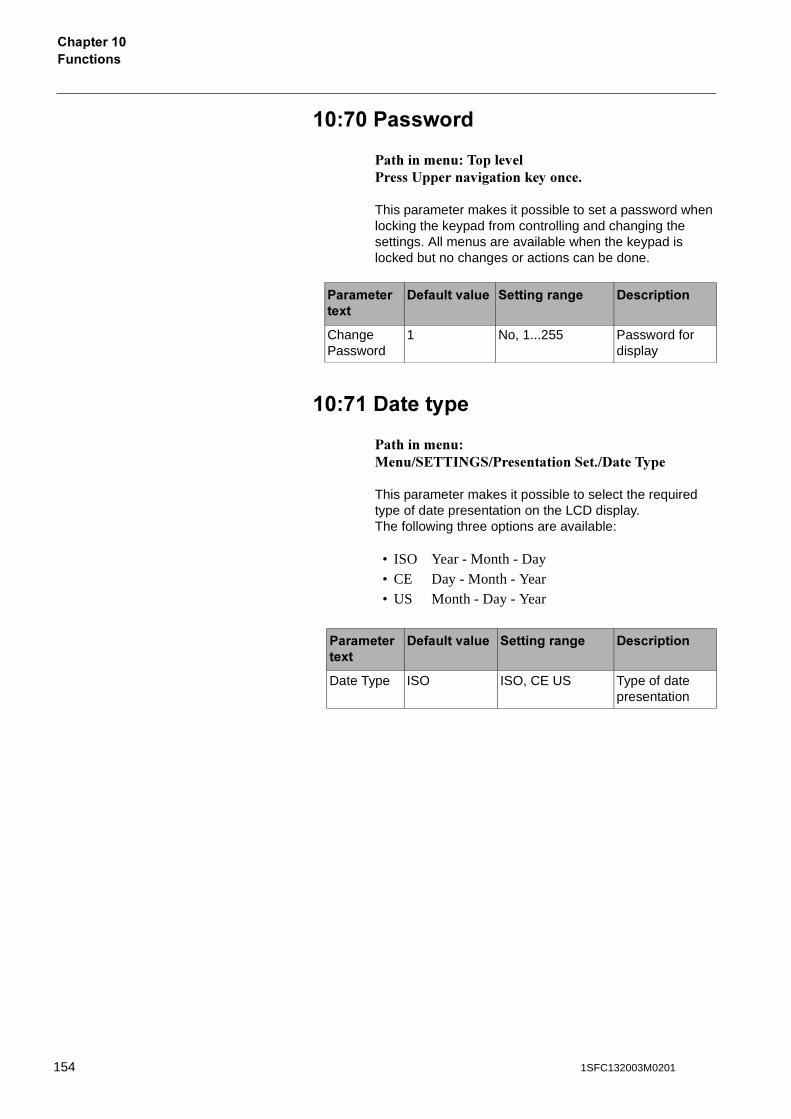
7��������������� �
��*� ���=���
������������������*���������,������*������)�������"
This parameter makes it possible to set a password when locking the keypad from controlling and changing the settings. All menus are available when the keypad is locked but no changes or actions can be done.
��* -�������
������������ ���������� ��������������"�%������
This parameter makes it possible to select the required type of date presentation on the LCD display. The following three options are available:
• ISO Year - Month - Day• CE Day - Month - Year• US Month - Day - Year
����������8�
-������<���� ������������ -����������
Change Password
1 No, 1...255 Password for display
����������8�
-������<���� ������������ -����������
Date Type ISO ISO, CE US Type of date presentation
154 1SFC132003M0201
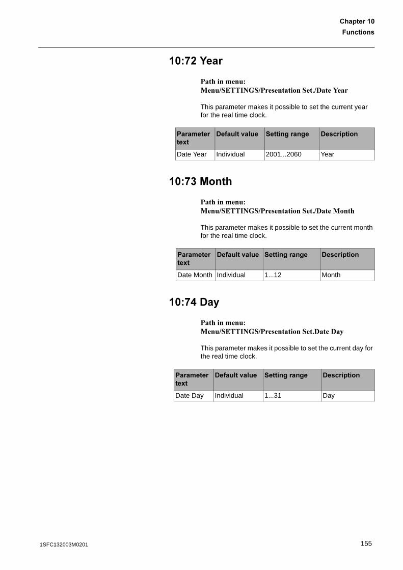
7��������
������� �
��*% G���
������������ ���������� ��������������"�%��<��
This parameter makes it possible to set the current year for the real time clock.
��*� /����
������������ ���������� ��������������"�%�� ���
This parameter makes it possible to set the current month for the real time clock.
��*. -��
������������ ���������� ��������������"%��%�
This parameter makes it possible to set the current day for the real time clock.
����������8�
-������<���� ������������ -����������
Date Year Individual 2001...2060 Year
����������8�
-������<���� ������������ -����������
Date Month Individual 1...12 Month
����������8�
-������<���� ������������ -����������
Date Day Individual 1...31 Day
1551SFC132003M0201
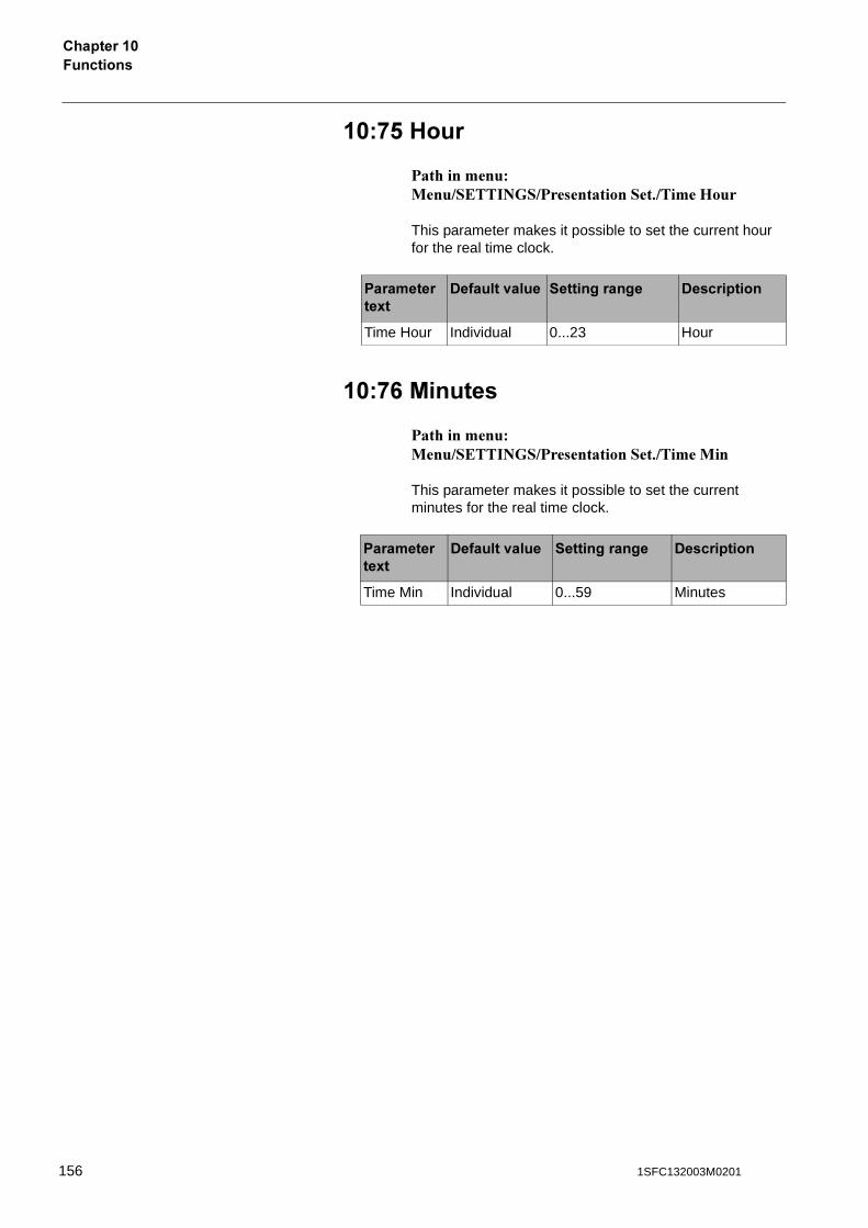
7��������������� �
��*! 1���
������������ ���������� ��������������"������.���
This parameter makes it possible to set the current hour for the real time clock.
��*0 /������
������������ ���������� ��������������"������ ��
This parameter makes it possible to set the current minutes for the real time clock.
����������8�
-������<���� ������������ -����������
Time Hour Individual 0...23 Hour
����������8�
-������<���� ������������ -����������
Time Min Individual 0...59 Minutes
156 1SFC132003M0201

��������������
������� ��������������
General ............................................................................................................ 159
General problems and faults .......................................................................... 159
Start up faults .................................................................................................. 160
Fault indication ................................................................................................ 161
Protection indication ........................................................................................ 164
1571SFC132003M0201

158 1SFC132003M0201
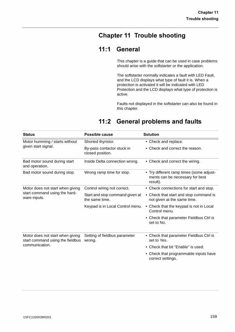
��������������
�������
������� ��������������
� "������
This chapter is a guide that can be used in case problems should arise with the softstarter or the application.
The softstarter normally indicates a fault with LED Fault, and the LCD displays what type of fault it is. When a protection is activated it will be indicated with LED Protection and the LCD displays what type of protection is active.
Faults not displayed in the softstarter can also be found in this chapter.
�% "�����������������������
������ ������������ ��������
Motor humming / starts without given start signal.
Shorted thyristor.
By-pass contactor stuck in closed position.
• Check and replace.
• Check and correct the reason.
Bad motor sound during startand operation.
Inside Delta connection wrong. • Check and correct the wiring.
Bad motor sound during stop. Wrong ramp time for stop. • Try different ramp times (some adjust-ments can be necessary for best result).
Motor does not start when giving start command using the hard-ware inputs.
Control wiring not correct.
Start and stop command given at the same time.
Keypad is in Local Control menu.
• Check connections for start and stop.
• Check that start and stop command is not given at the same time.
• Check that the keypad is not in Local Control menu.
• Check that parameter Fieldbus Ctrl is set to No.
Motor does not start when giving start command using the fieldbus communication.
Setting of fieldbus parameter wrong.
• Check that parameter Fieldbus Ctrl is set to Yes.
• Check that bit "Enable" is used.
• Check that programmable inputs have correct settings.
1591SFC132003M0201
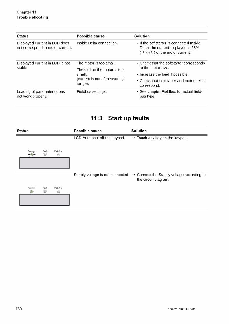
���������������������
�� �������������
Displayed current in LCD doesnot correspond to motor current.
Inside Delta connection. • If the softstarter is connected Inside Delta, the current displayed is 58%( ) of the motor current.
Displayed current in LCD is not stable.
The motor is too small.
Theload on the motor is too small.(current is out of measuring range).
• Check that the softstarter corresponds to the motor size.
• Increase the load if possible.
• Check that softstarter and motor sizes correspond.
Loading of parameters doesnot work properly.
Fieldbus settings. • See chapter Fieldbus for actual field-bus type.
������ ������������ ��������
LCD Auto shut off the keypad. • Touch any key on the keypad.
Supply voltage is not connected. • Connect the Supply voltage according to the circuit diagram.
������ ������������ ��������
1 3� ��
Power on ProtectionFault
Power on ProtectionFault
160 1SFC132003M0201
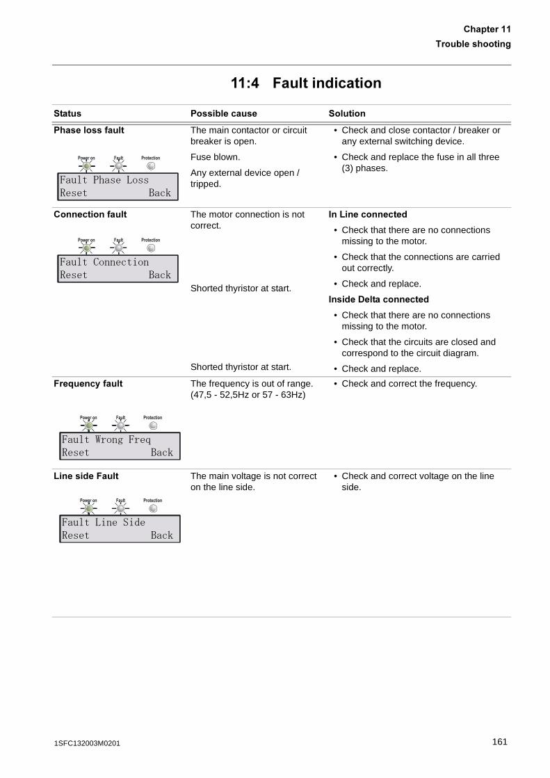
��������������
�������
�. 7��������������
������ ������������ ��������
������������� The main contactor or circuit breaker is open.
Fuse blown.
Any external device open / tripped.
• Check and close contactor / breaker or any external switching device.
• Check and replace the fuse in all three (3) phases.
��������������� The motor connection is not correct.
Shorted thyristor at start.
Shorted thyristor at start.
��B������������
• Check that there are no connections missing to the motor.
• Check that the connections are carried out correctly.
• Check and replace.
������-�������������
• Check that there are no connections missing to the motor.
• Check that the circuits are closed and correspond to the circuit diagram.
• Check and replace.
7��;���������� The frequency is out of range.(47,5 - 52,5Hz or 57 - 63Hz)
• Check and correct the frequency.
B�������7���� The main voltage is not correct on the line side.
• Check and correct voltage on the line side.
Power on ProtectionFault
-������+�"�!�""&"� ����
Power on ProtectionFault
-��������������&"� ����
Power on ProtectionFault
-�����1�����-�9&"� ����
Power on ProtectionFault
-�����!�����'&"� ����
1611SFC132003M0201
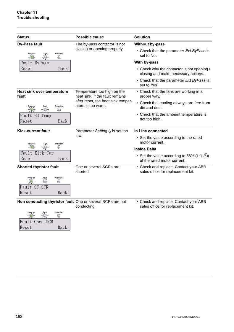
���������������������
��2 �������� The by-pass contactor is not closing or opening properly.
(��������2����
• Check that the parameter ��������� is set to No.
(�����2����
• Check why the contactor is not opening / closing and make necessary actions.
• Check that the parameter ��������� is set to Yes
1������,�<��2����������������
Temperature too high on the heat sink. If the fault remains after reset, the heat sink temper-ature is too warm.
• Check that the fans are working in a proper way.
• Check that cooling airways are free from dirt and dust.
• Check that the ambient temperature is not too high.
A��,2������������ Parameter ����� � is set too
low.��B������������
• Set the value according to the rated motor current.
������-����
• Set the value according to 58% ( ) of the rated motor current.
��������������������� One or several SCRs are shorted.
• Check and replace. Contact your ABB sales office for replacement kit.
9�������������������������� One or several SCRs are not conducting.
• Check and replace. Contact your ABB sales office for replacement kit.
������ ������������ ��������
Power on ProtectionFault
-������%��""&"� ����
Power on ProtectionFault
-�����:��*� &"� ����
Power on ProtectionFault
-�����2���6���&"� ����
1 3� ��
Power on ProtectionFault
-����������&&"� ����
Power on ProtectionFault
-����� ����&&"� ����
162 1SFC132003M0201
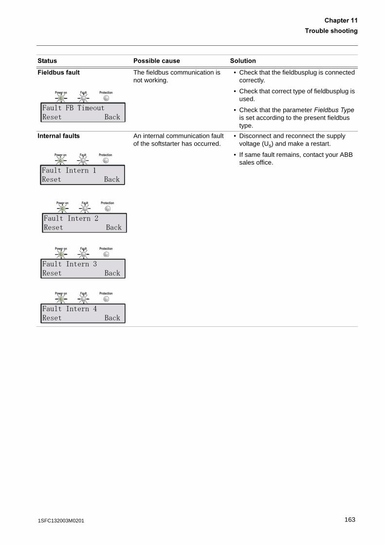
��������������
�������
7������������ The fieldbus communication is not working.
• Check that the fieldbusplug is connected correctly.
• Check that correct type of fieldbusplug is used.
• Check that the parameter�"� ��������� is set according to the present fieldbus type.
�������������� An internal communication fault of the softstarter has occurred.
• Disconnect and reconnect the supply voltage (Us) and make a restart.
• If same fault remains, contact your ABB sales office.
������ ������������ ��������
Power on ProtectionFault
-�����-��*�����&"� ����
Power on ProtectionFault
-�����������#&"� ����
Power on ProtectionFault
-�����������4&"� ����
Power on ProtectionFault
-�����������5&"� ����
Power on ProtectionFault
-�����������;&"� ����
1631SFC132003M0201
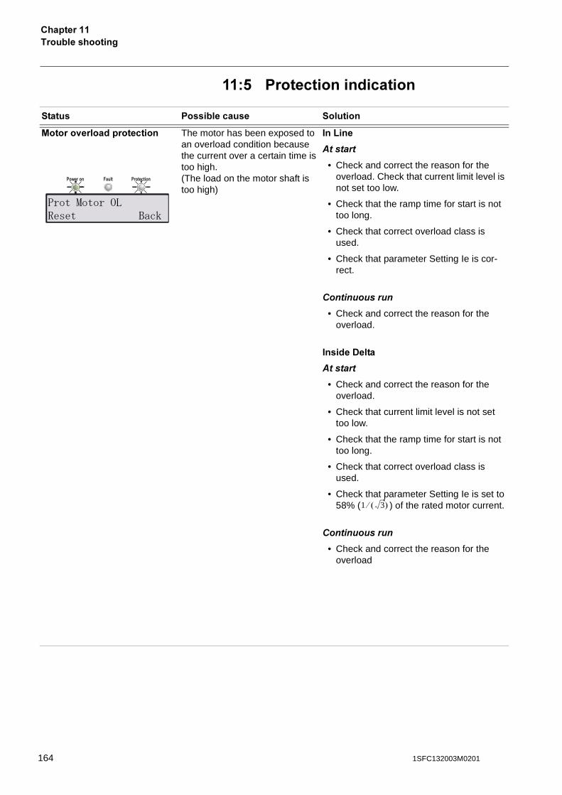
���������������������
�! �������������������
������ ������������ ��������
/�����<���������������� The motor has been exposed to an overload condition because the current over a certain time is too high.(The load on the motor shaft is too high)
��B���
��������
• Check and correct the reason for the overload. Check that current limit level is not set too low.
• Check that the ramp time for start is not too long.
• Check that correct overload class is used.
• Check that parameter Setting Ie is cor-rect.
����������
• Check and correct the reason for the overload.
������-����
��������
• Check and correct the reason for the overload.
• Check that current limit level is not set too low.
• Check that the ramp time for start is not too long.
• Check that correct overload class is used.
• Check that parameter Setting Ie is set to 58% ( ) of the rated motor current.
����������
• Check and correct the reason for the overload
Power on ProtectionFault
���������� !&"� ����
1 3� ��
164 1SFC132003M0201
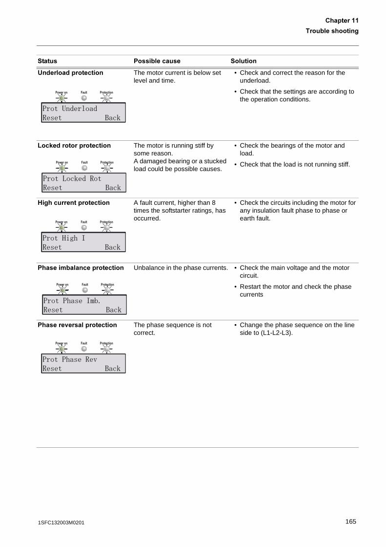
��������������
�������
&������������������ The motor current is below set level and time.
• Check and correct the reason for the underload.
• Check that the settings are according to the operation conditions.
B��,����������������� The motor is running stiff by some reason.A damaged bearing or a stucked load could be possible causes.
• Check the bearings of the motor and load.
• Check that the load is not running stiff.
1�������������������� A fault current, higher than 8 times the softstarter ratings, has occurred.
• Check the circuits including the motor for any insulation fault phase to phase or earth fault.
����������������������� Unbalance in the phase currents. • Check the main voltage and the motor circuit.
• Restart the motor and check the phase currents
������<��������������� The phase sequence is not correct.
• Change the phase sequence on the line side to (L1-L2-L3).
������ ������������ ��������
Power on ProtectionFault
�������'����'&"� ����
Power on ProtectionFault
�����!���'�&��&"� ����
Power on ProtectionFault
�����:��+��&"� ����
Power on ProtectionFault
������+�"���<�&"� ����
Power on ProtectionFault
������+�"�&3&"� ����
1651SFC132003M0201
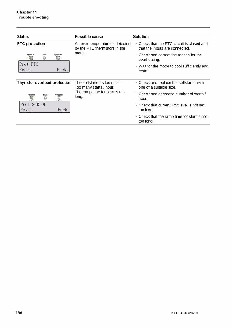
���������������������
����������� An over-temperature is detected by the PTC thermistors in the motor.
• Check that the PTC circuit is closed and that the inputs are connected.
• Check and correct the reason for the overheating.
• Wait for the motor to cool sufficiently and restart.
���������<���������������� The softstarter is too small.Too many starts / hour.The ramp time for start is too long.
• Check and replace the softstarter with one of a suitable size.
• Check and decrease number of starts / hour.
• Check that current limit level is not set too low.
• Check that the ramp time for start is not too long.
������ ������������ ��������
Power on ProtectionFault
������*�&"� ����
Power on ProtectionFault
�������&� !&"� ����
166 1SFC132003M0201

-�������
������� %-�������
Circuit diagram PST30..PST300 ..................................................................... 169
Circuit diagram PSTB370...PSTB1050............................................................ 170
1671SFC132003M0201

168 1SFC132003M0201
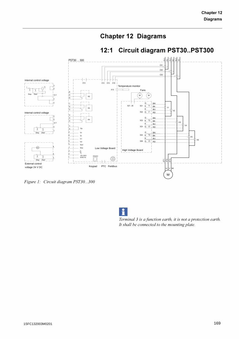
-�������
������� %
������� %-�������
%� �������������� ����� ����
������ &��������������!�������������������������� ������������������������ ����
RS323
1L1
B1
3L2
B2
5L3
B3
�����"# �����������%��&1���&11
Internal control voltage
External control
voltage 24 V DC
Internal control voltage
Temperature monitor
Low Voltage BoardHigh Voltage Board
FieldbusPTCKeypad
Fans
1691SFC132003M0201
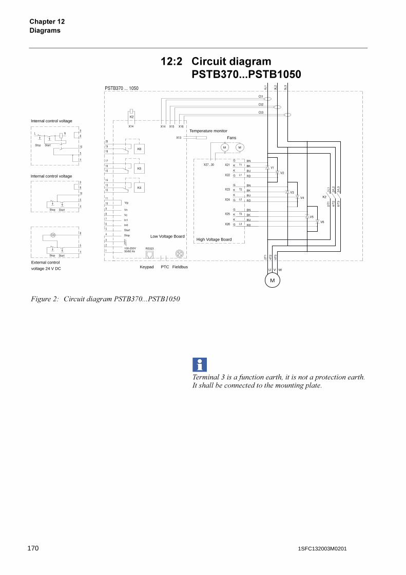
-�������������� %
%�% �������������� ���*���� �� �!�
������ &��������������!�������������������������� ������������������������ ����
�����$# �����������%��4&,1���%��4"1*1
Internal control voltage
External control
voltage 24 V DC
Internal control voltage
Temperature monitor
Low Voltage BoardHigh Voltage Board
FieldbusPTCKeypad
Fans
170 1SFC132003M0201
����8
������� �����8
9�������1st Seq. Param. ��, ���, ���1st Set Ie ��, ���2nd Seq .Param. ��2nd Seq. Param. ���, ���2nd Set Ie ��, ���3rd Seq .Param. ��3rd Seq. Param. ���, ���3rd Set Ie ��3rdSet Ie ���
#Abbreviations ��Acronyms ��Active ��Airways ��All settings �, �, ��Altitude ��Analog input telegram ���Analog output telegram ��Application Setting �, �, �, �AS-I ��, ���, ��Axial Fan �
�Basic settings �, �, �Binary input telegram ���, ���Binary output telegram ���, ��Bow Thruster �BP Fault Op ��, ��Bypass
AC3 ��By-Pass fault ��
Type of operation ��, ��
�Centrifugal Fan �Centrifugal Pump �Change Password Changed settings �, �Circuit diagram ��Communication devices, connection ��Communication protocols ��Compressor �Configuration �Connection ��, ��, �
Communication devices ��Control circuit ��Earthing ��Main circuit ��Programmable inputs ��Programmable output relay K4 �Programmable output relay K5 �Programmable output relay K6 �PTC input �Standard ��Start and Stop ��
Connection fault ��Connections ��
Control circuit ��Connection ��
Conventional circuit ��Conveyor �Cooling ��, ��Cooling system ��Crusher �CT Ratio Ir ��Current ���Current Lim �Current limit ��, �, ���
Curr Lim1 ���Curr Lim2 ���Curr Lim3 ���Current Lim ���First sequence ��, ���Level �, �Second sequence ��, ���Third sequence ��, ���
-Date ���
Day ��, ���Hour ��, ��Minutes ��, ��Month ��, ���Type ��Year ��, ���
Day ���Description ��Description of menus DeviceNet ��, ���, ��Diagnostic inputs ���Dimensions ��Display at start up Document ID �Document number �DOL start ��, ��Drilling plan ��, ��Dual Class R ��Dual Class S ��
?Earthing
Connection ��Edition �Electrical connection
Earthing ��External By-Pass ��Main circuit ��Programmable inputs ��Programmable output relay K4 �Programmable output relay K5 �Programmable output relay K6 �PTC input �Start and Stop ��Supply voltage and control circuit ��
Enclosure sizes ��End Volt �, ���End voltage �, �, �, ���
1711SFC132003M0201
����8
Environmental influence ��Event �Event log ��, �Ext ByPass �, �, ��Extended start range ��, ���Extended stop range ��, ���External By-Pass �, �, ��
Connection ��Contactor �, �
External By-Pass contactor ��External control voltage ��
7Fans ��Fault ��Fault Supervision ��Faults ��, ���Faults indication ��FB Fault Op ��, ���Fieldb Addr ��, ��Fieldb Ctrl ��, ��Fieldb Type ��, ��Fieldbus ��, ��, ��
Address ��Communication ��Connection ��Control ��, ��Fault ��Type ��, ��
Fieldbus faultType of operation ��, ���
Fieldbusplug ��First programmable input ��First sequence parameters ��Freq F Op ��Frequency ��, �Frequency fault ��
Freq F Op ���Type of operation ��, ���
Frequency out of range ��Function earth ��Functional Settings �, �, �Functions ��Fuse ��
1Hardware ��Hardware inputs control ��Heat sink over-temperature fault ��
Type of operation ��, ���High current
Type of operation �High current protection ��, �, ���, ��
Type of operation ���High current warning ��, ��, ��High current warning level ��, ���High I �, ���High I Op �, ���HMI ��Holding circuit ��Hour ��, ��HS Temp Op ��, ���Human-Machine Interface ��Humidity ��
Hydraulic Pump �
�In Line ��In0 ��, ��, ���In1 ��, ��, ���Industrial IT ��Init Volt �, ���Init Volt1 ���Init Volt2 ���Init Volt3 ���Initial voltage ��, �, �, �, ���
First sequence ��, ���Second sequence ��, ���Third sequence ��, ���
Input address map ��Inputs ��Inside Delta ��Insulation ��Int Bypass ��Internal control voltage ��Internal faults ��, ��
CJog ��, ��, ��
AKeypad ��, ��, ��
Locking ��Password ��, ��, ���Status Unlocking ��
Kick Level �, �, ���Kick Start ��, �, �, ���Kick Start Level �, �, ���Kick Start Time �, ���Kick StartTime �Kick Time �, �, ���
BLanguage ��, ���LCD ��, ��LCD Auto Off ��, ���LCD display automatic switch off ���LED ��, ��Line side ��Line side Fault ��LOCAL CONTROL �Local Control menu ��Lock R Lev ���Lock R Op , ���Lock R Time , ���Locked Rotor , ���Locked rotor
Time Type of operation
Locked rotor level Locked rotor protection ��, , ���, ��
Level , ���Time , ���Trip level ���Type of operation , ���
172 1SFC132003M0201
����8
Low current warning ��, ��, ���Level ��, ���
LV Board No �
/MAC Address �Main circuit ��
connection ��Maintenance ���Markings ��Menu tree �Menus, description Minimum distance to wall/front ��Minimum enclosure sizes ��Minutes ��, ��Mixer �Month ���Motor overload protection ��, �, ���, ��
OL Class �, ��OL Op �, ��Overload class �, �Run class Start class Type of operation �, ��
Motor overload warning ��, ���Motor side ��Motor sound ���Motor temperature Motor underload protection ��, ���Mounting ��
9Navigation keys ��No of Seq ��, ���No. Of Starts �Non conducting SCR ��, ��Non conducting thyristor fault ��
>OL Class �, �, �, , ��OL Class R OL Op �, ��Open circuit motor side ��Output address map ���Output relays ��Outputs �Overload �, ��, ���Overload Class �Overload class �, �, �, ��
Dual type, run class ��Dual type, start class ��
Overload protectiontype of operation ��
Overload run class Overload start class Overload type of operation �Overload warning ��, ���Overload warning level ��, ���Over-temperature heat sink ��Overview ��
Parameters ���Password ��, ���Password, setting ��Ph Imb Lev ���Ph Imb Op �Ph Loss Op ��, ���Ph Rev Op ���Phase Imb �, ���Phase Imb Op ���Phase imbalance �
Level �Type of operation �
Phase imbalance protection ��, �, ���, ��Level �, ���Type of operation ���
Phase L1 �Phase L2 �Phase L3 �Phase loss ��Phase loss fault ��
Type of operation ��, ���Phase Rev ��, ���Phase reversal ��
Type of operation ��Phase reversal protection ��, ��, ���, ��
Type of operation ��, ���Phase seq. �Pollution degree ��Presentation Set ���Presentation Settings ��Presentation settings �, �, ��Programmable inputs ��, ��, ���
Connection ��Programmable output relay K4 �, �, ���
Connection �Programmable output relay K5 �, �, ���
Connection �Programmable output relay K6 �, �, ���
Connection �Programmable software output V7 �, ���Protection ��, ��, ��, �Protection indication ��Protections �PTC Op ��, ��PTC protection ��, ��, ���, �
Connection �Type of operation ��, ��
+Quickstart ��
:Real time clock ��, Relay K4 �, �, ���Relay K5 �, �, ���Relay K6 �, �, ���Requirements �Reset all settings �, �, �Run Time �
1731SFC132003M0201
����8
�S Port Addr1 ��S Port Addr2 ��S Port Addr3 ��S Port Addr4 ��S Port Ctrl ��SCR overload protection ��, ��SCR overload warning ���SCR SC Op ��, ���SCR shorted ��, ��SCR temperature Second programmable input ��Second sequence parameters ��Selection keys ��Sequence start ��, ��
First sequence setting current ��Function of first programmable input ��Function of second programmable input ��Number of sequences ��, ���Second sequence setting current ��Third sequence setting current ��
Service settings �, ��Setting current �, ���
First sequence ��, ���Second sequence ��, ���Third sequence ��, ���
Setting Ie �, ��, �, �, �, ���Settings �Settings menu �Shorted SCR ��, ��Shorted SCR type of operation ��Shorted thyristor fault ��Softstarter types �SOP1 ��SOP2 ��SOP3 ��SOP4 ��Specifications ��Standard connection ��Start �Start and Stop
Connection ��Start ramp ��, �, �, �, ���
First sequence ��, ���Range �, ���Second sequence ��, ���Third sequence ��, ���
Start Ramp1 ���Start Ramp2 ���Start Ramp3 ���Start range �, �, ���Start up faults ��Start/Stop ��, ��, ��, �
Circuits, connection ��Status Information menu �Status of inputs/outputs Step down �, ���Step down voltage ��, �, �, ���Stop Ramp
Range ���Stop ramp ��, �, �, �, ���
Range �, �, ���Stop range �, �, ���
Storage ��, ��Supply voltage ��, ��Supply voltage and control circuit, connection ��SW Outp V7 �, ���SW Ver. CU �SW Ver. FU �
Technical data ��Temperature ��Thermistor ��Third sequence parameters ��Thyristor overload protection �Thyristor overload warning ��, ��, ���Thyristor short circuit fault
Type of operation ��, ���Time Hour ��Time Min ��Top level �, Trouble shooting ���Tune Set �Tuning parameters �Type designation ��Type of operation �
&Uin status Underl Lev �, ���Underl Op �, ���Underl Time �, ���Underload �, ��
Level �Time �, ���Type of operation �, ���
Underload protection �, ���, ��Level �, ���Time �, ���Type of operation �, ���
Unlocking the keypad ��Unpacking ��
(Wa I=H Lev ��, ���Wa I=L Lev ��, ���Wa OL Lev ��, ���Warn I=High ��, ��Warn I=Low ��, ���Warn OL ��, ���Warn SCR OL ��, ���Warning ��Warning high current ��
Level ��Warning low current ��
Level ��Warning overload ��
Level ��Warning SCR overload ��Warnings ��Weights �
174 1SFC132003M0201
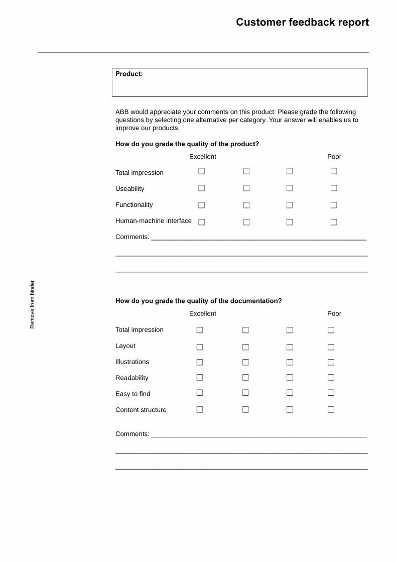
���������������,������
�������
ABB would appreciate your comments on this product. Please grade the following questions by selecting one alternative per category. Your answer will enables us to improve our products.
1�=�������������;������������������I
Excellent Poor
Total impression
Useability
Functionality
Human-machine interface
Comments: __________________________________________________________
____________________________________________________________________
____________________________________________________________________
1�=�������������;������������������������I
Excellent Poor
Total impression
Layout
Illustrations
Readability
Easy to find
Content structure
Comments: __________________________________________________________
____________________________________________________________________
____________________________________________________________________
Rem
ove
from
bin
der
Rem
ove
from
bin
der
�������������������<������
_____________________________________________________________________
_____________________________________________________________________
_____________________________________________________________________
_____________________________________________________________________
_____________________________________________________________________
_____________________________________________________________________
_____________________________________________________________________
_____________________________________________________________________
_____________________________________________________________________
_____________________________________________________________________
_____________________________________________________________________
_____________________________________________________________________
_____________________________________________________________________
_____________________________________________________________________
����������������������
ABB Automation Technology Products AB, ControlS-721 61 VästeråsSweden


AB
B A
utom
atio
n T
echn
olog
y P
rodu
cts
AB
/Con
trol
, SE
-721
61
Väs
terå
s, S
wed
en, T
elep
hone
+46
21
32 0
7 00
, Tel
efax
+46
21
12 6
0 01
Man
ual �
��������������
Mar
ch 2
003
AB
B A
utom
atio
n T
echn
olog
y P
rodu
cts
AB
/Con
trol
Prin
ted
in M
arch
200
3