Embed Size (px)
Citation preview

FRACTIONATIONTRAYS
02/03
INTRODUCTION
Hanbal Masstech Limited[HMT] is a leading company which designs and manufactures Tower Trays, Internals, Packings, Reactor Internals, Wire Mesh Demisters, Mist Eliminators, etc. Our company has been providing these products for Chemical Companies, Oil Refineries, Petrochemical Plants, etc., as well as Engineering and Construction Companies since being founded in 1971.
We joined Norton Chemical Process Products Corporation in 1979 as Sales Representatives and worked with them as the manufacturer, Joint Venture Partner[Norton Hanbal Korea Inc.], design/manufacturer and Licensee until April 2002.
We conducted R&D with the Korea Institute of Energy Resource [KIER]. Especially noteworthy has been the R&D undertaken with the KIER, Ruhr University in Germany, and Hanbal, as a Fractional Research Inc, [FRI] member for five years under government assistance. Our R&D with KIER contin-ues every year.
We have learned most of the design fabrication technologies from Norton CPPC, but we have some of our own that will meet our customer's specific requirements.
Since we know what and how Norton has tested, we built an indoor test facility, 12 meter indoor facil-ity, for distribution quality tests. What we have designed is unquestionable, we conduct tests to make sure our products are perfect.
We also design and produce traditional style internals which are good for easy towers and those costs are about 30% less compared to the high performance towers.
We thank you all for your help and concerns rendered to us so far and wish to do the same in the future.
Sincerely, President & CEO
FRACTIONATION TRAYS
TYPE OF TRAYS
TYPICAL TRAY LAYOUT AND HARDWARES
SELECTION OF TRAY TYPE AND THEIR FEATURES
THE TERMS MOST FREQUENTLY ASKED ON TRAYS
SPECIAL TRAY DESIGN FEATURES TO ENHANCE PERFORMANCE
DISLODGEMENT RESISTANCE TRAYS
NUMBER OF TRAY FLOW PATHS
TRAY CONSTRUCTION MATERIALS
INSTALLATION - DEMOLITION - SUPERVISION
QUALITY ASSURANCE AND CONTROL POLICY
04
05
06
07
08
09
10
10
11
11
04/05
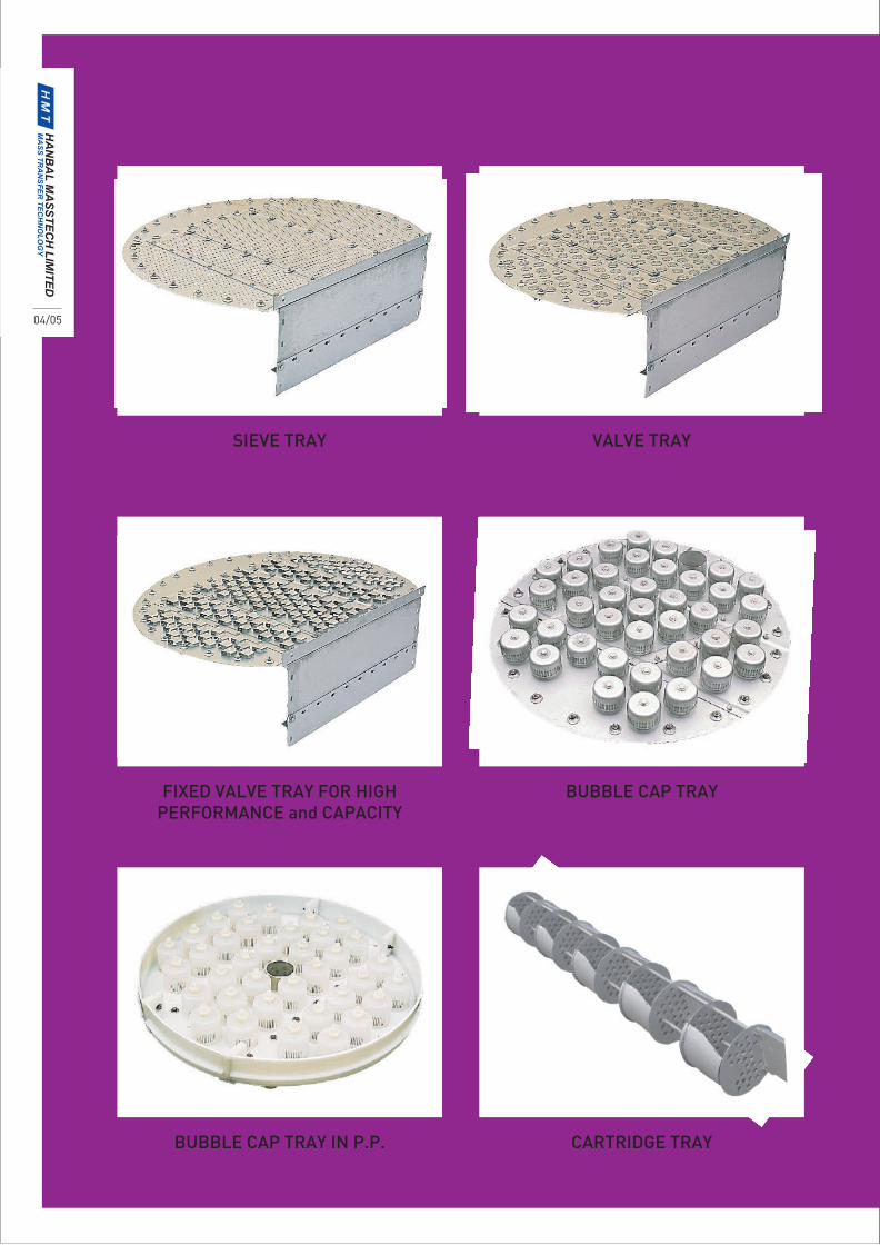
SIEVE TRAY
TYPE OF TRAYS
VALVE TRAY
FIXED VALVE TRAY FOR HIGHPERFORMANCE and CAPACITY
BUBBLE CAP TRAY
BUBBLE CAP TRAY IN P.P. CARTRIDGE TRAY
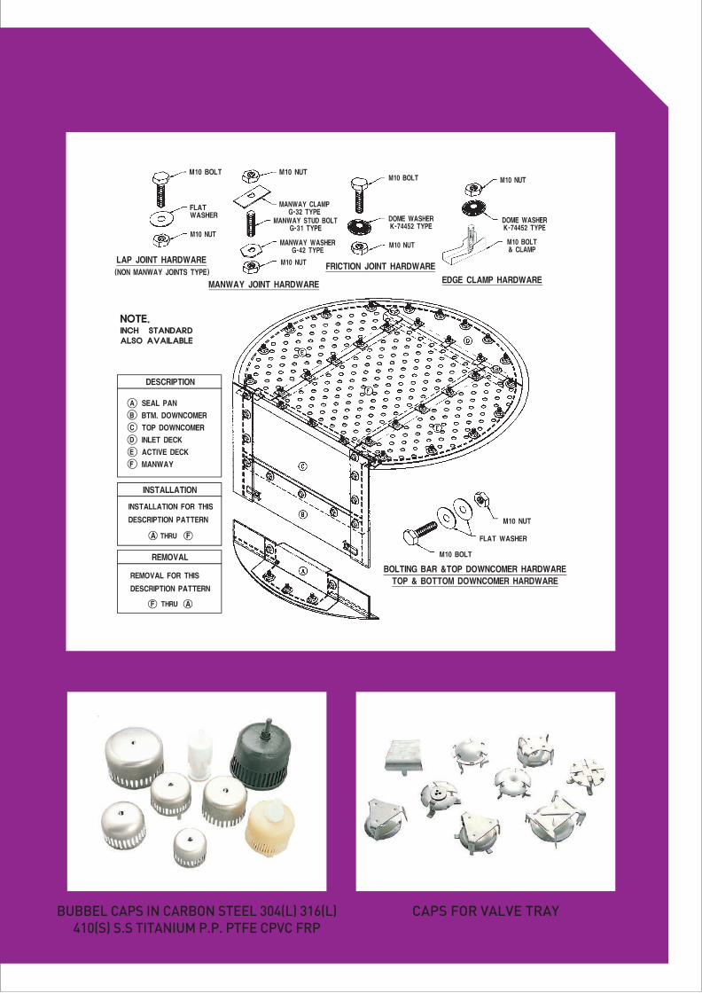
BUBBEL CAPS IN CARBON STEEL 304(L) 316(L)410(S) S.S TITANIUM P.P. PTFE CPVC FRP
CAPS FOR VALVE TRAY
TYPICAL TRAY LAYOUT AND HARDWARES
06/07
SELECTION OF TRAY TYPE AND THEIR FEATURES
The four basic types of fractionation trays are the perforated trays(sieve), valve trays, bubble cap trays and cartridge trays. In general, tray type selection is determined by evaluating various factors, such as process, cost, mechanical, installation and maintenance considerations. Some important areas of performance to be taken into account when selecting the type of tray are capacity, turn-down, efficiency, pressure drop, tendencies toward fouling and scaling, corrosion and actual histori-cal data from previous experiences in the system.
A brief overview of the benefits or disadvantages of each of the four basic conventional tray types are mentioned below:
Some less conventional trays such as dual-flow, side-to-side, and disc and donut trays are advanta-geous for special use where extremely high capacity, fouling and pressure drops are major consid-erations. Hanbal Masstech has the technology and the manufacturing capability to design and fabri-cate almost any type of conventional or specialty tray.
PERFORATED TRAYS are often used when a wide range of flexibility is not required and the lowest tray cost is desired. For very low rate applications, perforated trays are not a good choice. Some instances that require extensive blanking of perforations could result in an ultimate cost greater than valve trays. VALVE TRAYS which usually have a cost comparable to perforated trays, afford the widest operat-ing range and greatest capacity. Considering the additional operating range and capacity of valve trays over perforated trays, it can be concluded that valve trays are actually lower on costs. In many applications, vapor loading controls capacity. In many cases, valve trays may have as much as ten percent more capacity than perforated trays. Trays with valves comprised of three pieces (fixed caged, valve plate and orifice cover) have proven to be very efficient for glycol dehydrators and other services with low liquid rates. In many cases these valve trays can effectively be utilized to replace bubble cap trays (which are considerably more expensive) for these low liquid rate services. BUBBLE CAP TRAYS provide the lowest capacity and the highest cost conventional trays, but they are the best choice for use when leakage must be minimized. Bubble cap trays also require addi-tional installation time due to the need to gasket all of the tray joints to prevent leakage. CARTRIDGE TRAYS (which are shop prefabricated into bundles of 4 or 5 trays each, equipped with enveloped downcomers, peripheral packing glands and spacer rods) are a viable approach to the installation and removability of trays for towers which are too small for workman passage.
THE TERMS MOST FREQUENTLY ASKED ON TRAYS
ACTIVE AREA the mixing area of the tray(located between the inlet area and downcomer). FREE AREA available tower area for vapor flow (tower area less the maximum area in the top of the downcomer(s)). INLET WEIR barrier which is parallel and adjacent to the inlet downcomer. It evenly distributes the liquid flow and provides (in some cases) a liquid seal for the downcomer. Commonly used with valve trays to minimize leakage in the first rows of valves by creating a calming zone. TRAY INLET SUMP located at the inlet side of a tray for the purpose of controlling and assuringequal and even distribution of liquid flow across a tray floor. Also provides downcomer clearancefor high liquid rates. OUTLET (OVERFLOW) WEIR barrier located at the outlet side of the tray creating a seal with the downcomer from the tray above and maintaining liquid on the tray for proper vapor-liquid contact. DOWNCOMER device which transfers or directs liquid from one tray to the tray or equipment below. DOWNCOMER FLOODING excessive liquid velocity in the downcomer that prevents the vapor from disengaging the aerated liquid exiting the downcomer. These excessive downcomer liquid velocities result in low residence time and poor vapor disengagement. Premature flooding occurs when poor vapor disengagement reduces the density of the vapor/liquid mixture in the downcomer, prompting a higher liquid (ie vapor/liquid mixture) level than a higher liquid density. MANWAYS removable panels provided in trays or reinforced openings in tower shells which allow workman passage for installation, maintenance or inspection. COLLECTOR TRAY contains chimneys permitting passage of vapor upward through the tray. It is placed at various levels in the tower for accumulating and drawing off liquids. FLOODING unstable operation where the tower is full of (or in the process of filling with) liquid and/or liquid/vapor mixture. The two main causes of flooding are: excessive downcomer filling and excessive entrainment(jet flood.) SEAL PAN reservoir normally located below the bottom tray in a vessel to prevent vapor from by- passing the downcomer of the lowest tray. SUMP well or cavity which is used to collect all or a portion of liquid from a tray. TRAY EFFICIENCY ratio between the actual number of trays necessary and the number of theoretical equilibrium stages to accomplish a desired separation. WEEP HOLES punched through the tray deck at locations where the liquid would otherwise accumu-late and prevent complete tower drainage during shutdown. DUMPING condition where all the liquid leaks through the tray openings and none flows over the weir.
08/09
SPECIAL TRAY DESIGN FEATURES TO ENHANCE PERFORMANCE
Many of these special features can often greatly improve overall tray performance. Not only do we offer these features upon customer request, but in many cases, we suggest the use of them in instances where our experience indicates the benefits.
Some of these special features and explanations of their uses are as follows:
In addition to the special features listed above, Hanbal Masstech has experience in the utilization of many other tray enhancement features and is open to consideration of the use or development of any new ones that could improve performance in any way.
SWEPT-BACK WEIRS are side outlet weirs which are multichordal in lieu of a single chord design. This design is sometimes utilized for side flow trays of a multipass design to balance liquid loads or sometimes for a single pass tray to reduce the effective liquid height on the tray by decreasing the volume of liquid per unit length which flow over the outlet weir.
SPLASH BAFFLES are used to maximize the liquid retention time on trays used in very low liquid rate services. These baffles are located adjacent and parallel to the outlet weir and clear the tray deck and the outlet weir by 1/2" to 1" whereby exiting liquid is forced to flow under the baffle prior to flowing over the top of the outlet weir.
PICKET-FENCE BAFFLES are used to decrease effective weir length. They are often utilized in cases where the liquid flow over the weir would otherwise be less than one gpm per inch. Picket-fence baffles can increase the effective liquid height on the bubbling (active) area and reduce blowing". These baffles (which either attach or can be formed integrally with the outlet weir) are uniformly spaced to allow evenly distributed flow into the downcomer. They can be used in conjunction with splash baffles when both features are needed.
ANTI-JUMP DOWNCOMER BAFFLES are used on multipass trays for center and off-center down-comers when needed to prevent liquid which is flowing across the tray from blowing or jumping over the downcomer and onto the opposing flow path. When the width of the downcomer is small and the loading is high, these are particularly advantageous. SLOPED DOWNCOMERS WITH RECESSED INLET SUMPS can be effectively utilized in heavy liquid loaded services that would otherwise be prone to downcomer flooding.
ACTIVE AREA the mixing area of the tray(located between the inlet area and downcomer). FREE AREA available tower area for vapor flow (tower area less the maximum area in the top of the downcomer(s)). INLET WEIR barrier which is parallel and adjacent to the inlet downcomer. It evenly distributes the liquid flow and provides (in some cases) a liquid seal for the downcomer. Commonly used with valve trays to minimize leakage in the first rows of valves by creating a calming zone. TRAY INLET SUMP located at the inlet side of a tray for the purpose of controlling and assuringequal and even distribution of liquid flow across a tray floor. Also provides downcomer clearancefor high liquid rates. OUTLET (OVERFLOW) WEIR barrier located at the outlet side of the tray creating a seal with the downcomer from the tray above and maintaining liquid on the tray for proper vapor-liquid contact. DOWNCOMER device which transfers or directs liquid from one tray to the tray or equipment below. DOWNCOMER FLOODING excessive liquid velocity in the downcomer that prevents the vapor from disengaging the aerated liquid exiting the downcomer. These excessive downcomer liquid velocities result in low residence time and poor vapor disengagement. Premature flooding occurs when poor vapor disengagement reduces the density of the vapor/liquid mixture in the downcomer, prompting a higher liquid (ie vapor/liquid mixture) level than a higher liquid density. MANWAYS removable panels provided in trays or reinforced openings in tower shells which allow workman passage for installation, maintenance or inspection. COLLECTOR TRAY contains chimneys permitting passage of vapor upward through the tray. It is placed at various levels in the tower for accumulating and drawing off liquids. FLOODING unstable operation where the tower is full of (or in the process of filling with) liquid and/or liquid/vapor mixture. The two main causes of flooding are: excessive downcomer filling and excessive entrainment(jet flood.) SEAL PAN reservoir normally located below the bottom tray in a vessel to prevent vapor from by- passing the downcomer of the lowest tray. SUMP well or cavity which is used to collect all or a portion of liquid from a tray. TRAY EFFICIENCY ratio between the actual number of trays necessary and the number of theoretical equilibrium stages to accomplish a desired separation. WEEP HOLES punched through the tray deck at locations where the liquid would otherwise accumu-late and prevent complete tower drainage during shutdown. DUMPING condition where all the liquid leaks through the tray openings and none flows over the weir.
DISLODGEMENT RESISTACE TRAYS
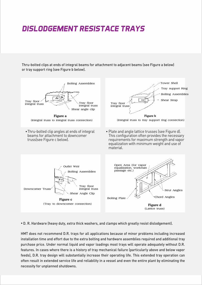
Thru-bolted clips at ends of integral beams for attachment to adjacent beams (see Figure a below) or tray support ring (see Figure b below).
Thru-bolted clip angles at ends of integral beams for attachment to downcomer truss(see Figure c below).
Plate and angle lattice trusses (see Figure d).This configuration often provides the necessary requirements for maximum strength and vapor equalization with minimum weight and use of material.
HMT does not recommend D.R. trays for all applications because of minor problems including increased installation time and effort due to the extra bolting and hardware assemblies required and additional tray purchase price. Under normal liquid and vapor loadings most trays will operate adequately without D.R. features. In cases where there is a history of tray mechanical failure (particularly above and below vapor feeds), D.R. tray design will substantially increase their operating life. This extended tray operation can often result in extended service life and reliability in a vessel and even the entire plant by eliminating the necessity for unplanned shutdowns.
D. R. Hardware (heavy duty, extra thick washers, and clamps which greatly resist dislodgement).
10/11
NUMBER OF TRAY FLOW PATHS
TRAY CONSTRUCTION MATERIALS
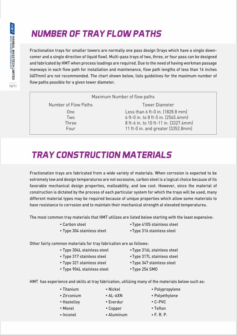
Fractionation trays for smaller towers are normally one pass design (trays which have a single down-comer and a single direction of liquid flow). Multi-pass trays of two, three, or four pass can be designed and fabricated by HMT when process loadings are required. Due to the need of having workman passage manways in each flow path for installation and maintenance, flow path lengths of less than 16 inches (407mm) are not recommended. The chart shown below, lists guidelines for the maximum number of flow paths possible for a given tower diameter.
Fractionation trays are fabricated from a wide variety of materials. When corrosion is expected to be extremely low and design temperatures are not excessive, carbon steel is a logical choice because of its favorable mechanical design properties, malleability, and low cost. However, since the material of construction is dictated by the process of each particular system for which the trays will be used, many different material types may be required because of unique properties which allow some materials to have resistance to corrosion and to maintain their mechanical strength at elevated temperatures.
Maximum Number of flow paths
Number of Flow PathsOneTwo
ThreeFour
Tower DiameterLess than 6 ft-0 in. (1828.8 mm) 6 ft-0 in. to 8 ft-5 in. (2565.4mm) 8 ft-6 in. to 10 ft-11 in. (3327.4mm) 11 ft-0 in. and greater (3352.8mm)
The most common tray materials that HMT utilizes are listed below starting with the least expensive:
Carbon steel Type 304 stainless steel
Type 410S stainless steelType 316 stainless steel
Other fairly common materials for tray fabrication are as follows:
HMT has experience and skills at tray fabrication, utilizing many of the materials below such as:
Type 304L stainless steel Type 317 stainless steel Type 321 stainless steel Type 904L stainless steel
Type 316L stainless steelType 317L stainless steelType 347 stainless steelType 254 SMO
Titanium Zirconium Hastelloy Monel Inconel
Nickel AL-6XN Everdur Copper Aluminum
PolypropylenePolyethyleneC-PVCTeflonF. R. P.
INSTALLATION AND SUPERVISION
QUALITY ASSURANCE AND CONTROL POLICY
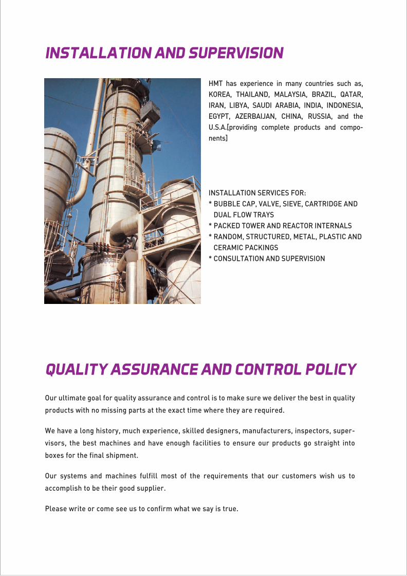
HMT has experience in many countries such as, KOREA, THAILAND, MALAYSIA, BRAZIL, QATAR, IRAN, LIBYA, SAUDI ARABIA, INDIA, INDONESIA, EGYPT, AZERBAIJAN, CHINA, RUSSIA, and the U.S.A.[providing complete products and compo-nents] INSTALLATION SERVICES FOR: * BUBBLE CAP, VALVE, SIEVE, CARTRIDGE AND DUAL FLOW TRAYS * PACKED TOWER AND REACTOR INTERNALS * RANDOM, STRUCTURED, METAL, PLASTIC AND CERAMIC PACKINGS * CONSULTATION AND SUPERVISION
Our ultimate goal for quality assurance and control is to make sure we deliver the best in quality
products with no missing parts at the exact time where they are required.
We have a long history, much experience, skilled designers, manufacturers, inspectors, super-
visors, the best machines and have enough facilities to ensure our products go straight into
boxes for the final shipment.
Our systems and machines fulfill most of the requirements that our customers wish us to
accomplish to be their good supplier.
Please write or come see us to confirm what we say is true.
Seoul Office200, Seochojungang-ro, Seocho-gu, Seoul, Korea Tel. +82 2 412 0851 / Fax. +82 2 413 0272
Main Office 46, Golden root-ro 66beon-gil, Juchon-myeon, Gimhae-si, Gyeongsangnam-do, KoreaTel. +82 55 310 2100 / Fax. +82 55 338 1917 / www.hanbal.kr


![Forno elettrico meccanico - prismafood.com · [56|57] SERIE TRAYS GLASS Medesime caratteristiche tecniche del modello TRAYS. Questa versione offre il vantaggio di una porta con vetro](https://img.pdfslide.tips/doc/110x75/5bb6d49909d3f2a4338c35ba/forno-elettrico-meccanico-5657-serie-trays-glass-medesime-caratteristiche.jpg)