Embed Size (px)
Citation preview
M. Milutinović, Lj. Tanović Sile rezanja kod tvrdog tokarenja koje uključuju stražnji pojas trošenja i njegov utjecaj na trenje izmedju alata i obratka
Tehnički vjesnik 23, 5(2016), 1373-1379 1373
ISSN 1330-3651 (Print), ISSN 1848-6339 (Online) DOI: 10.17559/TV-20140903224947
CUTTING FORCES IN HARD TURNING COMPRISING TOOL FLANK WEAR AND ITS IMPLICATION FOR THE FRICTION BETWEEN TOOL AND WORKPIECE Milan Milutinović, Ljubodrag Tanović
Original scientific paper In this paper, the orthogonal cutting force model is proposed comprising forces due to flank wear in addition to the forces for chip formation during the hard turning of round bar made of steel 60WCrV7 hardened at 55+2HRc. Cutting force model includes two tool conditions: perfectly sharp tool with VBB = 0 and tool with maximum permissible flank wear VBBmax. Based on cutting force measurements and established force relationships between the wear forces and forces for chip formation, it is possible to analytically predict the friction coefficient between the tool and workpiece. From pure geometrical relationships between forces the equation for the friction angle between the tool flank and workpiece can be derived. The friction coefficient at the tool-workpiece interface was measured using block-on-the-disc tribometer. Predictions of the friction coefficient by means of established mathematical model are compared with experimental results, and overall a good agreement is observed. Keywords: cutting forces; flank wear; friction; hard turning Sile rezanja kod tvrdog tokarenja koje uključuju stražnji pojas trošenja i njegov utjecaj na trenje između alata i obratka
Izvorni znanstveni članak U ovom radu, predložen ortogonalni model sila rezanja obuhvaća sile nastale zbog trošenja stražnje površine pored sila za formiranje čestica pri tvrdom tokarenju okrugle šipke napravljene od čelika 60WCrV7 koja je otvrdnuta na 55+2 HRc. Model sila rezanja obuhvaća dva stanja alata: idealno oštar alat s VBB = 0 i alat s maksimalno dopuštenim pojasom istrošenja stražnje površine VBBmax. Na osnovu mjerenja sila rezanja i uspostavljenih odnosa između sila zbog trošenja stražnje površine alata i sila za odvajanje čestica, moguće je analitički predvidjeti faktor trenja između pojasa istrošenja stražnje površine alata i obratka. Iz geometrijskih odnosa između sila može se izvesti jednadžba kuta trenja alata i obratka. Faktor trenja između alata i obratka mjeren je pomoću tribometra blok-na-disku. Predviđanja faktora trenja pomoću uspostavljenog matematičkog modela uspoređena su s eksperimentalnim rezultatima i uočena su dobra poklapanja. Ključne riječi: sile rezanja; trošenje alata; trenje; tvrdo tokarenje 1 Introduction
In general, turning is one of the most important manufacturing operations because parts manufactured by casting, forming or some other shaping process often require further metal cutting operation before the product is ready for use [1]. Hard turning process is recognized as the single point turning of materials with hardness from 45 to 70 HRc [2] and it has been used as a potential alternative to costly, yet environmentally harmful, grinding process [3, 4, 5]. Hard turning can offer attractive benefits in terms of lower equipment costs, shorter setup time, better surface integrity and the elimination of cutting fluid.
During the cutting process, tool wear is an inevitable phenomenon, which is often used in evaluating the performance of a machining process [6]. Tool wear in hard turning is a gradual process that can be described by means of one or several wear mechanisms (abrasion, adhesion and diffusion). Two major wear zones are flank wear and crater wear. In most cases, flank wear is taken as a tool wear criterion because it causes significant increase in cutting forces that contribute to overall cutting force increase, machined surface roughness and machining accuracy [7].
Wang et al. [7] showed that tool flank wear does not statistically affect the basic cutting quantities such as shear angle, friction angle and shear stress but results in an additional wear force on the wearland, which can be incorporated in a model of chip formation in conventional turning process. Also Wang and Liu [8] supported the assumption that forces due to chip formation in hard turning should be coupled with forces due to flank wear.
Flank wear is the result of the frictional action between the tool flank and workpiece causing the occurrence of wear forces besides the shear force. It is obvious that friction is a crucial parameter in many engineering applications when contact surfaces are subjected to heat and wear. Some important investigations considering friction between the flank wear and workpiece have been reported [9, 10]. Waldorf et al. [9] considered that under finishing conditions, when the uncut chip thickness is of the order of the cutting edge radius, a wear force becomes significant as compared to the cutting forces. Armarego et al. [11] suggested that the friction coefficient at the tool-chip interface probably depends on the friction between the tool flank and workpiece and rake angle.
This paper deals with cutting forces in hard turning comprising the flank wear effect in addition to the forces for chip formation. Based on the cutting force measurements friction coefficient between the tool flank and workpiece can be predicted analytically. Force model includes two tool conditions: perfectly sharp tool with VBB = 0 and tool with maximum permissible flank wear VBBmax. The force model includes flank wear effect and it is based on Merchant’s classical thin shear zone analysis. To this end, the classical orthogonal cutting analysis proposed by Merchant and Wang’s orthogonal cutting model for tool with flank wear will be briefly reviewed first.
2 Cutting force models-brief review Most orthogonal cutting analyses are based on a model proposed by Merchant et al. [12].Total force is
Cutting forces in hard turning comprising tool flank wear and its implication for the friction between tool and workpiece M. Milutinović, Lj. Tanović
1374 Technical Gazette 23, 5(2016), 1373-1379
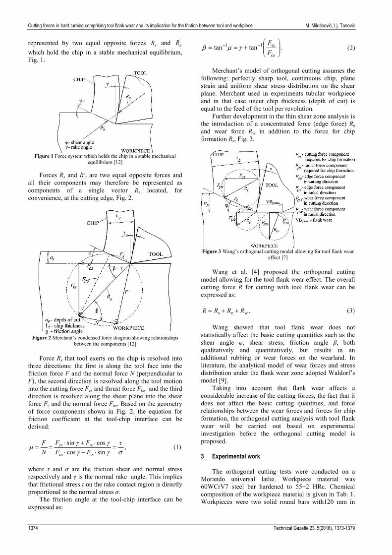
represented by two equal opposite forces sR and 'sR
which hold the chip in a stable mechanical equilibrium, Fig. 1.
Figure 1 Force system which holds the chip in a stable mechanical
equilibrium [12]
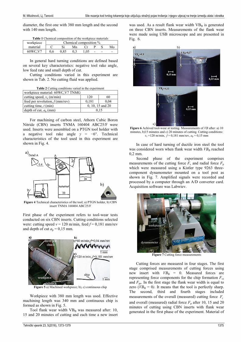
Forces Rs and R's are two equal opposite forces and all their components may therefore be represented as components of a single vector Rs located, for convenience, at the cutting edge, Fig. 2.
Figure 2 Merchant’s condensed force diagram showing relationships
between the components [12]
Force Rs that tool exerts on the chip is resolved into three directions: the first is along the tool face into the friction force F and the normal force N (perpendicular to F), the second direction is resolved along the tool motion into the cutting force Fcs and thrust force Fts, and the third direction is resolved along the shear plane into the shear force Fs and the normal force Fns. Based on the geometry of force components shown in Fig. 2, the equation for friction coefficient at the tool-chip interface can be derived:
,sin cos
cossin
tscs
tsc
st
γγγγ
µ =⋅−⋅⋅+⋅
==FFFF
NF s (1)
where τ and σ are the friction shear and normal stress respectively and γ is the normal rake angle. This implies that frictional stress τ on the rake contact region is directly proportional to the normal stress σ.
The friction angle at the tool-chip interface can be expressed as:
. tantancs
ts11
+== −−
FF
γµβ (2)
Merchant’s model of orthogonal cutting assumes the
following: perfectly sharp tool, continuous chip, plane strain and uniform shear stress distribution on the shear plane. Merchant used in experiments tubular workpiece and in that case uncut chip thickness (depth of cut) is equal to the feed of the tool per revolution.
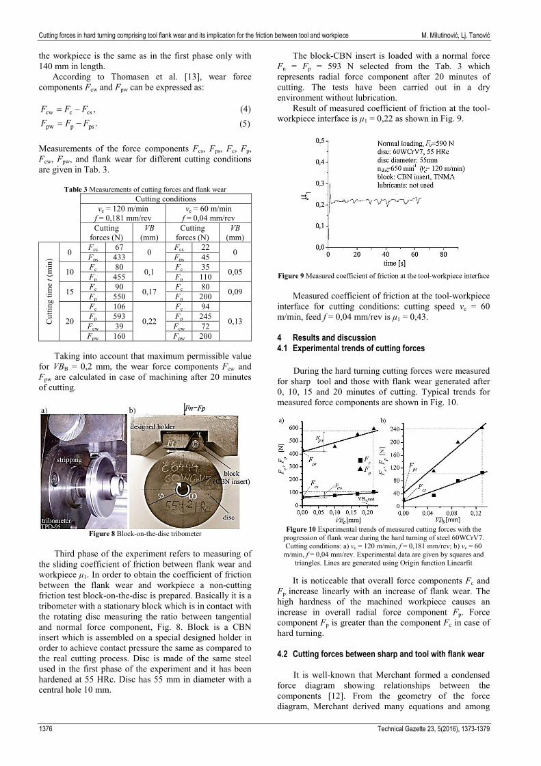
Further development in the thin shear zone analysis is the introduction of a concentrated force (edge force) Re and wear force Rw in addition to the force for chip formation Rs, Fig. 3.
Figure 3 Wang’s orthogonal cutting model allowing for tool flank wear
effect [7]
Wang et al. [4] proposed the orthogonal cutting model allowing for the tool flank wear effect. The overall cutting force R for cutting with tool flank wear can be expressed as:
.wes RRRR ++= (3)
Wang showed that tool flank wear does not statistically affect the basic cutting quantities such as the shear angle φ, shear stress, friction angle β, both qualitatively and quantitatively, but results in an additional rubbing or wear forces on the wearland. In literature, the analytical model of wear forces and stress distribution under the flank wear zone adopted Waldorf’s model [9].
Taking into account that flank wear affects a considerable increase of the cutting forces, the fact that it does not affect the basic cutting quantities, and force relationships between the wear forces and forces for chip formation, the orthogonal cutting analysis with tool flank wear will be carried out based on experimental investigation before the orthogonal cutting model is proposed. 3 Experimental work
The orthogonal cutting tests were conducted on a Morando universal lathe. Workpiece material was 60WCrV7 steel bar hardened to 55+2 HRc. Chemical composition of the workpiece material is given in Tab. 1. Workpieces were two solid round bars with120 mm in
M. Milutinović, Lj. Tanović Sile rezanja kod tvrdog tokarenja koje uključuju stražnji pojas trošenja i njegov utjecaj na trenje izmedju alata i obratka
Tehnički vjesnik 23, 5(2016), 1373-1379 1375
diameter, the first one with 380 mm length and the second with 140 mm length.
Table 1 Chemical composition of the workpiece materials workpiece material
Chemical composition % C Si Mn Cr P S Mo
60WCrV7 0,6 0,85 0,3 1,05 - - -
In general hard turning conditions are defined based on several key characteristics: negative tool rake angle, low feed rate and small depth of cut.
Cutting conditions varied in this experiment are shown in Tab. 2. No cutting fluid was applied.
Table 2 Cutting conditions varied in the experiment workpiece material: 60WCrV7 TNMG cutting speed, vc (m/min) 120 60 feed per revolution, f (mm/rev) 0,181 0,04 cutting time, t (min) 0, 10, 15 and 20 depth of cut, ap (mm) 0,15
For machining of carbon steel, Athorn Cubic Boron
Nitride (CBN) inserts TNMA 160404 ABC25/F were used. Inserts were assembled on a PTGN tool holder with a negative tool rake angle γ = −6°. Technical characteristics of the tool used in this experiment are shown in Fig. 4.
Figure 4 Technical characteristics of the tool; a) PTGN holder, b) CBN insert TNMA 160404 ABC25/F
First phase of the experiment refers to tool-wear tests conducted on six CBN inserts. Cutting conditions selected were: cutting speed v = 120 m/min, feed f = 0,181 mm/rev and depth of cut ap = 0,15 mm.
Figure 5 a) Machined workpiece; b), c) continuous chip
Workpiece with 380 mm length was used. Effective
machining length was 340 mm and continuous chip is formed as shown in Fig. 5.
Tool flank wear width VBB was measured after: 10, 15 and 20 minutes of cutting and each time a new insert
was used. As a result flank wear width VBB is generated on three CBN inserts. Measurements of the flank wear were made using USB microscope and are presented in Fig. 6.
Figure 6 Achived tool-wear at testing. Measurements of VB after: a) 10 minutes, b)15 minutes and c) 20 minutes of cutting. Cutting conditions:
vc =120 m/min, f = 0,181 mm/rev, ap = 0,15 mm
In case of hard turning of ductile iron steel the tool was considered worn when flank wear width VBB reached 0,2 mm. Second phase of the experiment comprises measurements of the cutting force Fc and radial force Fp which were measured using a Kistler type 9263 three- component dynamometer mounted on a tool post as shown in Fig. 7. Amplified signals were recorded and processed by a computer through an A/D converter card. Acquisition software was Labwiev.
Figure 7 Cutting force measurements
Cutting forces are measured in four stages. The first
stage comprised measurements of cutting forces using new insert with VBB = 0. Measured forces are representing force components for the chip formation Fcs and Fps. In the first stage the flank wear width is equal to zero (VBB = 0). It means that the tool is perfectly sharp. The second, third and fourth stages included measurements of the overall (measured) cutting force cF and overall (measured) radial force Fp after 10, 15 and 20 minutes of cutting using CBN inserts with flank wear generated in the first phase of the experiment. Material of
Cutting forces in hard turning comprising tool flank wear and its implication for the friction between tool and workpiece M. Milutinović, Lj. Tanović
1376 Technical Gazette 23, 5(2016), 1373-1379
the workpiece is the same as in the first phase only with 140 mm in length. According to Thomasen et al. [13], wear force components Fcw and Fpw can be expressed as:
,csccw FFF −= (4) .psppw FFF −= (5)
Measurements of the force components Fcs, Fps, Fc, Fp, Fcw, Fpw, and flank wear for different cutting conditions are given in Tab. 3.
Table 3 Measurements of cutting forces and flank wear Cutting conditions
vc = 120 m/min f = 0,181 mm/rev
vc = 60 m/min f = 0,04 mm/rev
Cutting forces (N)
VB (mm)
Cutting forces (N)
VB (mm)
Cut
ting
time
t (m
in)
0 Fcs 67 0 Fcs 22 0 Fps 433 Fps 45
10 Fc 80 0,1 Fc 35 0,05 Fp 455 Fp 110
15 Fc 90 0,17 Fc 80 0,09 Fp 550 Fp 200
20
Fc 106
0,22
Fc 94
0,13 Fp 593 Fp 245 Fcw 39 Fcw 72 Fpw 160 Fpw 200
Taking into account that maximum permissible value
for VBB = 0,2 mm, the wear force components Fcw and Fpw are calculated in case of machining after 20 minutes of cutting.
Figure 8 Block-on-the-disc tribometer
Third phase of the experiment refers to measuring of
the sliding coefficient of friction between flank wear and workpiece μ1. In order to obtain the coefficient of friction between the flank wear and workpiece a non-cutting friction test block-on-the-disc is prepared. Basically it is a tribometer with a stationary block which is in contact with the rotating disc measuring the ratio between tangential and normal force component, Fig. 8. Block is a CBN insert which is assembled on a special designed holder in order to achieve contact pressure the same as compared to the real cutting process. Disc is made of the same steel used in the first phase of the experiment and it has been hardened at 55 HRc. Disc has 55 mm in diameter with a central hole 10 mm.
The block-CBN insert is loaded with a normal force Fn = Fp = 593 N selected from the Tab. 3 which represents radial force component after 20 minutes of cutting. The tests have been carried out in a dry environment without lubrication.
Result of measured coefficient of friction at the tool-workpiece interface is μ1 = 0,22 as shown in Fig. 9.
Figure 9 Measured coefficient of friction at the tool-workpiece interface
Measured coefficient of friction at the tool-workpiece
interface for cutting conditions: cutting speed vc = 60 m/min, feed f = 0,04 mm/rev is μ1 = 0,43. 4 Results and discussion 4.1 Experimental trends of cutting forces
During the hard turning cutting forces were measured for sharp tool and those with flank wear generated after 0, 10, 15 and 20 minutes of cutting. Typical trends for measured force components are shown in Fig. 10.
Figure 10 Experimental trends of measured cutting forces with the
progression of flank wear during the hard turning of steel 60WCrV7. Cutting conditions: a) vc = 120 m/min, f = 0,181 mm/rev; b) vc = 60
m/min, f = 0,04 mm/rev. Experimental data are given by squares and triangles. Lines are generated using Origin function Linearfit
It is noticeable that overall force components Fc and
Fp increase linearly with an increase of flank wear. The high hardness of the machined workpiece causes an increase in overall radial force component Fp. Force component Fp is greater than the component Fc in case of hard turning. 4.2 Cutting forces between sharp and tool with flank wear
It is well-known that Merchant formed a condensed force diagram showing relationships between the components [12]. From the geometry of the force diagram, Merchant derived many equations and among
M. Milutinović, Lj. Tanović Sile rezanja kod tvrdog tokarenja koje uključuju stražnji pojas trošenja i njegov utjecaj na trenje izmedju alata i obratka
Tehnički vjesnik 23, 5(2016), 1373-1379 1377
them the friction coefficient at the tool-chip interface given in Eq. (1). Using the experimental trends of measured cutting forces shown in Fig. 10 relationship between force components for shear process and wear force components can be established as shown in Fig. 11.
Figure 11 Cutting force relationships between sharp and tool with flank wear. Cutting conditions: a) vc = 120 m/min, f = 0,181 mm/rev; b) vc =
60 m/min, f = 0,04 mm/rev
Experimental trend of cutting forces shows that the force Rs that tool exerts on the chip has almost the same slope as the wear force Rw. This means that vectors Rs and Rw are collinear.
However, the same or similar results can be obtained by the analysis of experimental results by Huanget al. [2], which can be presented in the same manner as the experimental results in this paper, Fig. 12.
Figure 12 Cutting force relationships between sharp and tool with flank wear based on experimental results given in [2]. Machined workpiece
was 52100 bearing steel with hardness 62 HRc. Cutting conditions: vc = 90 m/min; ap = 0,2 mm; f = 0,076 mm/rev
Mentioned experimental results confirm identical
cutting force relationships as presented in the experimental part of this paper. 4.3 Proposed cutting force model including tool flank wear
Since tool wear does not affect the basic chip formation process and assuming that the worn flank face is parallel to the cutting direction, overall (measured) force components Fc and Fp are the superposition of the wear force components Fcw and Fpw and force components from shearing Fcs and Fps [13]. Based on these facts and taking into account cutting force relationships between the forces for sharp tool and tool with flank wear, given in the experimental part of this paper, the orthogonal cutting force model with flank wear is proposed, Fig. 13. Force R and its components can be expressed as:
,ws RRR += (6)
,cwcsc FFF += (7) .pwpsp FFF += (8)
It is well-known that due to the friction between the
flank and workpiece, wear forces could occur in the vicinity of the cutting edge.
Figure 13 Proposed orthogonal cutting force model comprising flank
wear effect
There have been many attempts to determine the friction coefficient during machining. Many similar modes have been established such as pin-on-the disc or block-on-the-disc methods in order to identify the friction coefficient mostly between the tool rake face and the chip [10]. There are several ways to determine the friction coefficient between the flank and workpiece: estimating the stress distribution on the rake and flank surface [10], using Waldorf’s model that can analytically determine force components due to wear [9] or to measure overall cutting force components and identify μ1 according to Eq. (9).
.p
c1 F
F=µ (9)
In general, between the force Rs and overall force R
there is angle ς . For the case of experiments conducted in this paper the values of angle ς are between 0° and 3°. The friction angle at the tool-chip interface is defined in Eq. (2). Based on the geometry of the proposed orthogonal force model shown in Fig. 13 the equation for the friction angle between the tool flank and workpiece can be derived as:
.901 ςγββ −−−°= (10)
Friction coefficient, μ1, between flank wear and
workpiece can be expressed as:
Cutting forces in hard turning comprising tool flank wear and its implication for the friction between tool and workpiece M. Milutinović, Lj. Tanović
1378 Technical Gazette 23, 5(2016), 1373-1379
. tan )(
tan tan p
c
pwps
cwcs11
=
++
==FF
FFFF
βµ (11)
According to the cutting force relationship between
the sharp and tool with flank wear, the force Rs is almost collinear with the wear force Rw which implies that, for this case, the angle °≈ 0ς friction angle at the tool-workpiece interface can be derived as:
.901 γββ −−°= (12)
Based on Eq. (12), it can be concluded that the
friction angle between the tool flank and workpiece depends on the friction angle at the tool-chip interface and the rake tool angle. This statement implies that small uncut chip thickness generates small friction on the rake tool surface and friction on the flank surface becomes dominant. For the spatial case, when angle °≈ 0ς and rake angle γ = 0° the sum of friction angles β and β1 equals 90 degrees. Proposed model for prediction of the friction coefficient between the tool flank and workpiece requires only friction angle β, which can be easily calculated using Eq. 2, and rake tool angle γ. Based on measured force components for the chip formation Fcs and Fps given in Tab. 3, the friction angle β can be calculated, and using Eq. (10) and Eq. (11) the friction coefficient μ1 can be calculated. Measured and predicted friction coefficients between the tool flank and workpiece are shown in Tab. 4 and overall a good agreement is observed.
Table 4 Measured and predicted values of μ1 Cutting
conditions Measured μ1 Predicted μ1 Absolute
error vc = 120 m/min f = 0,181 mm/rev 0,22 0,19 0,03
vc = 60 m/min f = 0,04 mm/rev 0,43 0,38 0,05
5 Conclusion
In this paper a series of experiments were conducted during the hard turning of the round bar made of steel 60WCrV7 hardened to 55 HRc. During the longitudinal turning process under the practical cutting conditions the following can be concluded: - after 20 minutes of cutting, the flank wear reached
maximum permissible value, - overall (measured) cutting forces Fc and Fp increase
linearly with an increase of the flank wear. The high hardness of the machined workpiece cause an increase in overall radial force component Fp,
- radial wear force component Fpw is greater than wear force component Fcw which means that component Fp is more sensitive to tool flank wear and may be used as a primary basis for developing tool condition monitoring strategies,
- under finishing conditions, when the uncut chip thickness is of the order of the cutting edge radius, wear force components become significant as compared to the cutting forces for chip formation,
- experimental trend of cutting forces shows that force for chip formation Rs has almost the same slope as the wear force Rw.
Based on experimental results cutting force model comprising flank wear is proposed. From pure geometrical relationships between force component for chip formation and force components due to wear, the friction coefficient at the tool-workpiece interface can be predicted analytically. From Eq. (12) can be concluded that coefficient of friction between tool flank and workpiece depends on the friction coefficient at the tool-chip interface and rake angle.
Predictions of the coefficient of friction μ1 by means of established model are compared with experimental measurements using block-on-the-disc method and overall a good agreement is observed. Achieved contact conditions on tribometer (normal load and sliding speed) meet real machining conditions especially at fine machining in which the proposed model can be applied. 6 References [1] Seker, U.; Kurt, A.; Ciftci, I. Design and construction of a
dynamometer for measurements of cutting forces during machining with linear motion. // Materials and Design. 23, (2002), pp. 355-360. DOI: 10.1016/S0261-3069(02)00013-4
[2] Huang, Y.; Liang, S. Modeling of cutting forces under hard turning conditions considering tool wear effect. // Transactions of the ASME. 127, (2005), pp. 262-270. DOI: 10.1115/1.1852571
[3] Chou, K.; Song, H. Tool nose radius effect on finish hard turning. // Journal of Materials Processing Technology. 148, (2004), pp. 259-268. DOI: 10.1016/j.jmatprotec.2003.10.029
[4] Čep, R.; Janasek, A.; Martinicky, B.; Sadilek, M. Cutting tool life tests of ceramic inserts for car engine sleeves. // Tehnicki vjesnik-Technical Gazette. 18, 2(2011), pp. 203-209.
[5] Čep, R.; Neslušan, M.; Barišić, B. Chip formation analysis during hard turning. // Strojarstvo, 50, 6(2008), pp. 337-345.
[6] Ee, K.; Li, P.; Balaji, A.; Jawahir, I.; Stevenson, R. Performance-based predictive models and optimization methods for turning operations and applications: Part 1-tool wear/tool life in turning with coated grooved tools. // Journal of Manufacturing Processes. 8(2006), pp. 54-66. DOI: 10.1016/S1526-6125(06)70102-5
[7] Wang, J.; Huang, C. Z.; Song, W. G. The effect of tool flank wear on the orthogonal cutting process and its practical implications. // Journal of Materials Processing Technology. 142(2003), pp. 338-346. DOI: 10.1016/S0924-0136(03)00604-6
[8] Wang, J.; Liu, C. The effect of tool flank wear on the heat transfer, thermal damage and cutting mechanics in finish hard turning. // CIRP annals. 48, 1(1999), pp. 53-58. DOI: 10.1016/S0007-8506(07)63130-8
[9] Waldorf, D.; DeVor, R.; Kapoor, S. An evaluation of ploughing models for orthogonal machining. // Transactions of ASME. 121, (1999), pp. 550-558. DOI: 10.1115/1.2833050
[10] Ulutan, D.; Özel, T. Determination of tool friction in presence of flank wear and stress distribution based validation using finite element simulations in machining of titanium and nickel based alloys. // Journal of Materials Processing Technology. 213, (2013), pp. 2217-2237. DOI: 10.1016/j.jmatprotec.2013.05.019
[11] Armarego, E.; Brown, R. The machining of metals. Prentice-Hall, 1977.
M. Milutinović, Lj. Tanović Sile rezanja kod tvrdog tokarenja koje uključuju stražnji pojas trošenja i njegov utjecaj na trenje izmedju alata i obratka
Tehnički vjesnik 23, 5(2016), 1373-1379 1379
[12] Merchant, E. Mechanics of the metal cutting process. I. Orthogonal cutting and a type 2 chip. // Journal of Applied Physics. 16, 5(1945), pp. 267-275. DOI: 10.1063/1.1707586
[13] Thomasen, E.; MacDonald, A.; Kobayashi, S. Flank friction studies with carbide tool reveal sublayer plastic flow. // Transaction of ASME. (1962), pp. 53-62. DOI: 10.1115/1.3667438
Authors’ addresses
M.Sc. Milan Milutinovic, PhD student Mechanical Engineering Faculty Kraljice Marije 16, 11000 Belgrade, Serbia E-mail: [email protected]
Ljubordrag Tanović, prof. PhD Mechanical Engineering Faculty Kraljice Marije 16, 11000 Belgrade, Serbia E-mail: [email protected]