Embed Size (px)
Citation preview

Integral Geometry Science, Inc.
神戸大学
磁気映像化ソフトウェア
Integral Geometry Science社の技術の粋を結集して開発した磁場を用いた映像化技術のソフトウエアを提供いたします。高精度 ・高速のセンサ制御や高品質画像処理技術など世界トップレベルのテクノロジーを集積しています
未来を創るToward future imaging technologies
Integral Geometry Science Inc.
グラフィックユーザーインターフェイス
Integral Geometry Science Inc.
〒 650-0047神戸市中央区港島南町1丁目5番6
神戸大学インキュベーションセンター電話 078-304-6047
Mail: [email protected]: http://ig-instrum.co.jp/
従来、電子部品の分析にはX線透過装置、レーザ抵
抗変化法を用いたOBIRCH、光映像 分析を用いた外
観検査装置、電気的インピーダンス法及び真空電子
ビーム照射法などが用いられていますが、電流を直接
映像化する装置が存在しないため、電子部品の開発時
に必ず遭遇する動作不良箇所を特定することが大変困
難でした。そのため電流の直接映像化へは大きな期待
が掛けられています。
また 環境問題が深刻化する中で、次世代リチウム2次
電池の開発は急務です。電池内部の電流経路を超高
分解能で映像化する画像診断システム、特にリチウム
硫黄2次電池、金属リチウム2次電池、リチウム銅2次電
池などの負極でのデンドライド発生を診断できれば、事
故を未然に防止する可能性がでてきます。磁気映像化
技術はこのような電極間の異常電流を効率よく検出する
ことができます。
適用分野
磁気映像化ソフトウェアを使用した磁場分布画像処理左: 再構成前の磁場分布データ右: 再構成後の電流コントラストデータ
センサの走査、信号の解析、画像処理
磁気映像化技術を用いた電池の映像化のフローチャート
試料の
固定・配線
スキャン装置GUIから操作
スタート磁場の水平成
分を測定(Hx,Hy)
FOCUS座標をインプットして
再構成
画像処理結果の画像表
示
磁場測定装置の制御から再構成解析までのソフトウェアの流れ

磁場計測の原理
磁場計測の方法
静的な磁場ベクトルのある方向成分をΦ(x,y,z) とするとマックスウエルの方程式から次式を満たすことがわかります
計測面をz=MESDZとし、磁場とそのz方向の微分を計測す
ると上記の方程式から任意のz座標における磁場の分布が計算できます。
ここで境界条件は、z=MESDZでfm(x,y,z)と(d/dz)fm(x,y,0)が与えられ、それぞれf(x,y),g(x,y)とします。これらをフーリエ変換したものをf(kx,ky),g(kx,ky)とおいています。Δx,Δz TMRセンサのそれぞれV,W方向のサイズです。(下図参照)
文字“神”の形状をした平面磁気源からの放射磁場を計測すると上側の図のようにぼやけた画像になるが本ソフトウエアを用いて解析すると下の図のように明瞭に結像する
再構成のコンピューターシミュレーション
再構成
測定データ再構成データ
計測データの解析
電子回路の電流パターを解析
Au wiring with 30μm width
Magnetic field image
交流法によりリチウム電池を解析
battery model Magnetic field image
サブサーフェスイメージング-インフラ検査-
2014 年4 月29 日 日刊工業新聞1 面
その他の詳細な資料は下記より無料ダウンロードできます。
Integral Geometry Sciencehttp://ig‐instrum.co.jp/index.html

Integral Geometry Science, Inc.
The University of Kobe
Magnetic Field Imaging Software
We offer you a novel imaging technology software developed by merging the best of IGS technologies. That is integrated with the world’s top-level IGS hardware technologies such as high speed and precise sensor control etc.
未来を創るToward future imaging technologies
Integral Geometry Science Inc.
Graphic User Interface (GUI)
Integral Geometry Science Inc.
Among conventional methodologies for failure analysis of
electric components, X-ray imaging system, OBIRCH (Optical
Beam Induced Resistance Charge method, the vacuum electron
beam irradiation method et al. are familiar. However, there has
not been a device which is capable of visualizing electric current,
and it has been difficult to identify failure parts in an electric
component under development. Therefore, our direct electric
current imaging technique is significantly expected.
Moreover, it is urgently necessary to develop the next
generation rechargeable batteries since the environment issue
has become more serious. Abnormal products of high energy
rechargeable batteries have crucial risks of explosion accidents.
An image diagnosis system with high resolution that visualize
electric current inside the batteries would prevent the accidents,
when it can especially diagnoses dendrite growth on an anode
of Lithium-sulfur secondly battery, Metal lithium secondly battery
and lithium-copper secondly battery. You can effectively detect
such electric current abnormalities between electrodes with
subsurface magnetic field imaging technology of IGS.
Application
High spatial resolution image Produced by magnetic field reconstruction software
Left: Magnetic field distribution before reconstructedRight: Electric current image after reconstructed
Sensor scanning, signal analysis, image processing
Battery Cell Imaging FlowchartSample Setup
Wiring & mounting at a holder
Operate the instrumentusing GUI
StartMeasuring both
horizontal components of
magnetic field vector
Magnetic field reconstruction at
the Focus coordinate
Display
The whole flowchart of image analysis from the dataacquisition to the magnetic field reconstruction
1-5-6 Minatojimaminamimachi,Chuo-ku, Kobe-shi, Hyogo, Japan 650-0047Kobe University Buisiness Incubation Center
Tel: 078-304-6047Mail: [email protected]
URL: http://ig-instrum.co.jp/
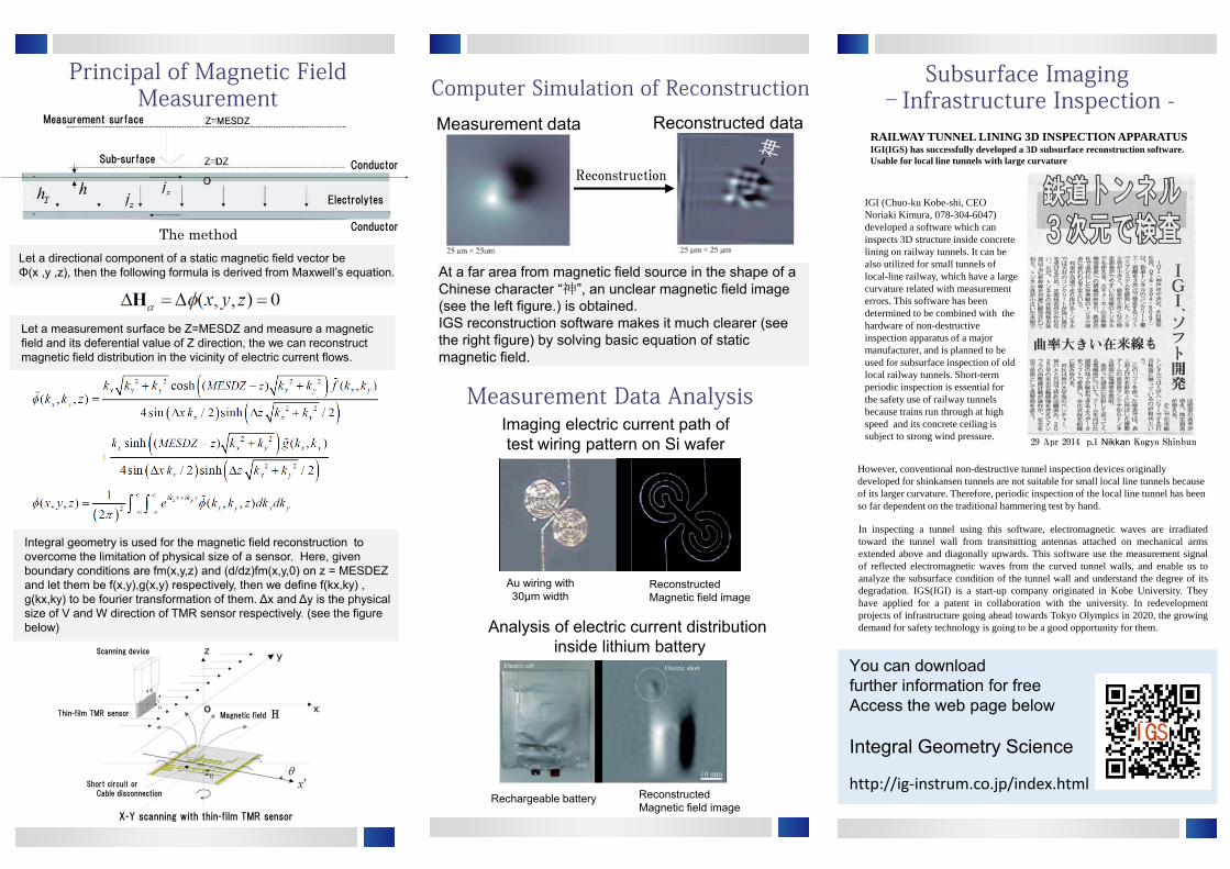
Principal of Magnetic Field Measurement
The methodLet a directional component of a static magnetic field vector be Φ(x ,y ,z), then the following formula is derived from Maxwell’s equation.
Let a measurement surface be Z=MESDZ and measure a magnetic field and its deferential value of Z direction, the we can reconstruct magnetic field distribution in the vicinity of electric current flows.
Integral geometry is used for the magnetic field reconstruction to overcome the limitation of physical size of a sensor. Here, given boundary conditions are fm(x,y,z) and (d/dz)fm(x,y,0) on z = MESDEZ and let them be f(x,y),g(x,y) respectively, then we define f(kx,ky) , g(kx,ky) to be fourier transformation of them. ∆x and ∆y is the physical size of V and W direction of TMR sensor respectively. (see the figure below)
At a far area from magnetic field source in the shape of a Chinese character “神”, an unclear magnetic field image (see the left figure.) is obtained. IGS reconstruction software makes it much clearer (see the right figure) by solving basic equation of static magnetic field.
Computer Simulation of Reconstruction
Reconstruction
Reconstructed dataMeasurement data
Measurement Data Analysis Imaging electric current path of test wiring pattern on Si wafer
Au wiring with 30μm width
Reconstructed Magnetic field image
Analysis of electric current distributioninside lithium battery
Rechargeable battery Reconstructed Magnetic field image
Subsurface Imaging –Infrastructure Inspection -
You can download further information for free Access the web page below
Integral Geometry Science
http://ig‐instrum.co.jp/index.html
Measurement surface
Sub-surfaceConductor
Conductor
Electrolytes
Scanning device
Thin-film TMR sensor
Short circuit orCable disconnection
X-Y scanning with thin-film TMR sensor
Magnetic field H
29 Apr 2014 p.1 Nikkan Kogyo Shinbun
IGI (Chuo-ku Kobe-shi, CEO Noriaki Kimura, 078-304-6047) developed a software which can inspects 3D structure inside concrete lining on railway tunnels. It can be also utilized for small tunnels of local-line railway, which have a large curvature related with measurement errors. This software has been determined to be combined with the hardware of non-destructive inspection apparatus of a major manufacturer, and is planned to be used for subsurface inspection of old local railway tunnels. Short-term periodic inspection is essential for the safety use of railway tunnels because trains run through at high speed and its concrete ceiling is subject to strong wind pressure.
In inspecting a tunnel using this software, electromagnetic waves are irradiatedtoward the tunnel wall from transmitting antennas attached on mechanical armsextended above and diagonally upwards. This software use the measurement signalof reflected electromagnetic waves from the curved tunnel walls, and enable us toanalyze the subsurface condition of the tunnel wall and understand the degree of itsdegradation. IGS(IGI) is a start-up company originated in Kobe University. Theyhave applied for a patent in collaboration with the university. In redevelopmentprojects of infrastructure going ahead towards Tokyo Olympics in 2020, the growingdemand for safety technology is going to be a good opportunity for them.
However, conventional non-destructive tunnel inspection devices originally developed for shinkansen tunnels are not suitable for small local line tunnels because of its larger curvature. Therefore, periodic inspection of the local line tunnel has been so far dependent on the traditional hammering test by hand.
RAILWAY TUNNEL LINING 3D INSPECTION APPARATUSIGI(IGS) has successfully developed a 3D subsurface reconstruction software.Usable for local line tunnels with large curvature

Integral Geometry Science, Inc.
神戸大学
電流経路映像化装置
電流分布測定受託計測開始: 平成24年11月磁場・電流映像化装置: 平成25年1月発売開始
当社は計測機器、信号・画像処理ソフトウエアの専門メーカです。 電子部品 , 電子機器の信頼性向上 , 社会インフラの予防保全 , 医療のために、最先端の検査技術の研究開発を通じて社会に貢献します。
大企業の研究所や大学でナノテク、プラズマやレーダなどの分野でトップレベルの高度な計測技術やソフトウエア開発を行った実績を持つ社員らで2012 年 4 月2日創立しました。神戸大学の研究者と密接な協力関係の下で研究開発を行い、世界最先端の技術を提供します。
未来を創るToward future imaging technologies
Integral Geometry Science Inc.
製品・サービス
○ 分析サービスプリント基板、LSI配線、SDカード、半導体素子、リチウムイオン電池セルなどの分析を受託します。
○ 磁気映像化装置標準型磁気映像化装置超高分解能磁気映像化装置(100nm)
Integral Geometry Science Inc.
〒 650-0047神戸市中央区港島南町1丁目5番6
神戸大学インキュベーションセンター電話 078-304-6047
Mail: [email protected]: http://ig-instrum.co.jp/
電子部品の微細化、集積化や高機能化が進み異常な電気特性 , 故障個所の特定がますます困難となってきています。例えば、・多層基板 ( 携帯電話用 , 大容量メモリカードなど 100 層以上 )・ディスプレイ用 TFT 配線( 高精彩画面の実現のため、配線幅の微細化(数μm)にともなう断線箇所の特定。・リチウムイオン電池の パッケージ内部電極の異常電流箇所 , 爆発事故の要因となる自己放電箇所などの特定。・ 最先端大規模集積回路の微細配線( 微細化 , 多層配線化が進展 , 数十 nm)
従来の研磨 + 表面観察の検査手法の限界 , 問題個所を除去 , 検査歩留りの悪化などから電子部品内部の高分解能非破壊画像検査手法の重要性が大となっています。従来からある X ray-Computed Tomography技術では 例えば電気的な欠陥個所、電流経路などの映像化が困難です。それに比べ磁気イメージング法では電子部品内部の電流経路を直接映像化することができます。従来の磁気イメージング法では空間分解能が磁気センサのサイズに依存していましたが、当社は独自に積分幾何学的再構成理論を用いた映像化技術を開発し、すべての製品にこの技術を搭載しています。磁気センサには薄膜トンネル磁気抵抗素子を使用しており薄膜の膜厚に迫る分解能(100nm)を可能としました。
背景
渦電流画像 電流経路画像
プリント基板の電流経路可視化画像
FOCUS004測定範囲: 150mm×150mm
走査速度: 最大100mm/sec
寸法: 100×60×80mm
重量: 約 80 kg


Integral Geometry Science, Inc.
The University of Kobe
Electric Current Microscope
Measurement service of electric current distribution:Since Nov 2012
Magnetic field and electric current imaging device
IGS is a manufacturer specializing in world’s front-line
measurement devices and image signal processing software.
IGS contributes to society by improving the reliability of
electronic parts and devices, preventive maintenance of
social-infrastructure and advancement of medical science
through research and development of cutting edge technology.
IGS was established on 2 April 2012 by effective and
experienced researchers who have developed top-level
measurement technology and software in the field of Nano
technology, plasma, radar and so on, in leading companies or
academic institutions. IGS provides the world’s most
advanced technic under the close corporation with academic
researchers.
未来を創るToward future imaging technologies
Integral Geometry Science Inc.
○ Measurement and Analysis Service
We provide measurement and analysis
services for Printed Circuit Boards(PCB), LSI,
SD cards, semiconductor devices and lithium-
ion battery cells etc.
○ Magnetic Field Imaging Device
You can chose from two types.
・Standard type
・Super high-resolution type(100nm)
1-5-6 Minatojimaminamimachi,
Chuo-ku, Kobe-shi, Hyogo, Japan 650-0047
Kobe University Buisiness Incubation Center
Tel: 078-304-6047
Mail: [email protected]
URL: http://ig-instrum.co.jp/
Miniaturization of electric components has been
accelerated, and identification of failure parts causing
abnormal electric characteristics has become more difficult.
For example,
・A multi-layer printed circuit board for cell phones or mass
storages, which has more than 100 layers.
・TFT wiring for displays – detection of wire breakage
associated with the miniaturization of wire width (a few
micro-meters) which realizes high resolution screen.
・Lithium-ion battery – detection of anomalous electric
currents inside a package and self-discharge which can
cause explosion accidents.
・ Extremely fine wiring of the forefront very-large-scale
Integrated Circuit, in the size of several tens of nanometers,
brought from the advancement of miniaturization.
The special resolution of conventional magnetic field
imaging strongly depends on the physical size of its
magnetic field sensor, and therefore, we have developed a
novel magnetic field reconstruction theory using integral
geometry mathematics in order to overcome the limitation.
Its magnetic sensors have thin-film Tunnel Magneto
Resistance devices , which provide high resolution reaching
to that of a thin film (below 100nm).
Eddy current image Current path image
Electric current images on printed circuit board
FOCUS004
Measurement range: 150mm×150mm
Scanning speed: Max 100mm/sec
Size: 100×60×80 mm
Weight: Around 80 kg
Invented on Mar 2015
Only needs one sec for imaging
Access to the Kobe office
To Sannomiya
Kobe-ohashi Bridge
Minatojima Tunnel
Minatojima St.
Shimin Hiroba St.
Iryo Center(Shimin Byoin Mae) St.
K coputer mae St.
Kobe Airport St.
IGS Kobe office(Kobe University Business Incubation Center)

Electric Current Microscope “Focus 001”
Reconstruction theory for imaging electric current inside rechargeable batteries
using measured magnetic field outside the ones.
High-speed reconstruction processing.
Considering stray magnetic field around the sensor
equipped with a cutting-edged thin film magnetic
sensor that operates at room temperature
Tunnel Magneto Resistance effect devises (200 pT/√Hz)
In a battery charging and discharging,
magnetic flux is leaked out.
Focus 001 measures the 2-dimensional
distribution of magnetic field outside battery
cell and reconstructs that of inside based on
the data. It gives internal information by solving
fundamental equation of electromagnetic field
by means of own method.
2D scanning
Magnetic field
Battery
Electric current
No need for an initial model for the inverse calculation,
In the case that its magnetic sensor and a measuring object are separated by a
passivating film, the measurement data is going to be blurry (see the left figure)
and it is impossible to identify the electric current pathway. However, you still can
get clear image with a IGS software independently developed in our laboratory.
(see the right figure). After reconstructing, you will notice that the left figure is
actually a electric current path representing a Chinese character “神” of 神戸大学(Kobe University).
When a malfunction occurs such as electric short-circuit or cable disconnection,
you can promptly determine the damaged part by non-destructive image
inspection. It is highly effective especially for complicated wiring.
It has been impossible to image a electric current under a metallic thin film by
optical method, however our method make it possible. The right figure shows
a case of success in finding a crack of wiring under a metallic thin film by
nondestructive inspection. If you break upper parts for the purpose of
inspection, the inside can be simultaneously damaged. That case means you
can inspect malfunctions internal multilayer board without destructing
In case that terminals are nonexistent so you cannot apply electric current or a
wiring pattern is unknown, it still visualizes wiring through a protective film.
1It visualizes electric current distribution clearly
when its magnetic sensor is apart from an object.
2 You can see how electric current flows on the
printed circuit board as an image
3 It visualizes a electric current under a metallic thin
film, which is impossible by optical method.
4 No need to apply an electric current for visualize
wiring.
5 It visualizes an inactive part inside battery in it
charging or discharging
It makes it visible inactive parts and self-discharge inside a battery. When an
inactive region spreads on electrode surfaces, it decreases chargeable energy.
You can inspect such malfunctions inside through a package during battery
charging or discharging.
6 It visualizes electric conductivity differences
between metals.
You can non-destructively inspect what sort of metals a measuring object
contains inside. We aim to apply this experiment to medical technology.
7
8
It visualizes an electric leak part between electrodes
of a capacitor structure (for capacitors or batteries)
As capacity of a capacitor or a battery increases, current leakage between
parallel plates has become a problem lately. This device visualizes a leakage
site with high resolution.
You can see a micron-scale and Nano-scale structure.
A spatial resolution generally depends on the size of its magnetic sensor. This
device has 2 types, 2μm-sensor and 1mm-sensor, so that you can chose
appropriate one according to a measuring object. Figures above shows magnetic
domain and a current path non-destructively visualized with 2μm-sensor.
Measurement data Reconstructed dataMagnetic field sensor
Measurement
surface
Sub-surface
4.5mmCurrent pathPassivating film
Power supply
Sample Reconstructed image
Magnetic field sensor of high sensitivity
Magnetic field
2 dimensional scanning
Cathode
Anode
Power supply
Inactive area
Au wiring with 30μm width Reconstructed Magnetic field imageReconstructed Magnetic field image
of a floppy disk
Scan area:128μm×128μm
Magnetic field sensor of high sensitivity
2 dimensional scanning
Magnetic field
Electrode
Electrode
Power supply
Leakage point
Electric conductivity
Cu (5.977×10⁷S/m)
CuZn (1.429×10⁷S/m)crack
Power supply
crack