Embed Size (px)
Citation preview
- Setup Instructions- PMEL Real-Time Altimeter for Seabird 9/11 CTD
NOAA, PMEL/EDD rev. 5/23/11
Setup Instructions: PMEL Real-Time Altimeter for Seabird 9/11 CTD
2
Table of Contents
Introduction………………………………………………………………………………. 3 Included Parts…………………………………………………………………………….. 4 Installation…………………………………………………………………………..……..8 Charging Altimeter Battery………………………………………………………………11 Configuring SBE Software………………………………………………………………12 Additional Notes……………………………………………………..…………………..15 Appendix…………………………………………………………………………………16

Setup Instructions: PMEL Real-Time Altimeter for Seabird 9/11 CTD
3
Introduction to Using CTD Altimeter Purpose The system is designed to allow real-time monitoring and logging of payload altitude from sea floor. Proper monitoring of data will allow deeper casts while minimizing risk of bottoming rosette. Estimated altimeter range is 0.5m<x<200m. System A battery powered Kongsberg 1007 Altimeter passes a voltage signal (pins 2 and 3, see Appendix B) through a SBE 911plus CTD, where signal is then transmitted up cable to ship-side data processing unit. Using SBE Seasave software, a conversion factor for the appropriate A/D channel converts the voltage signal into a corresponding altitude.
Setup Instructions: PMEL Real-Time Altimeter for Seabird 9/11 CTD
4
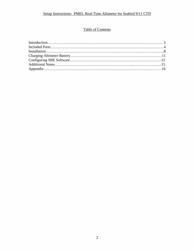
Included Parts 1) Battery case - tested to 10,000psi (Figure 1):
-Ti Lid (2-157 o-ring, 2-242 o-ring, 8-842 parbak, Ti pressure relief valve, purge plug, MCBH6F-Ti ½-20 connector, MCBH4M-Ti ½-20 connector, AG306 ½-20 connector).
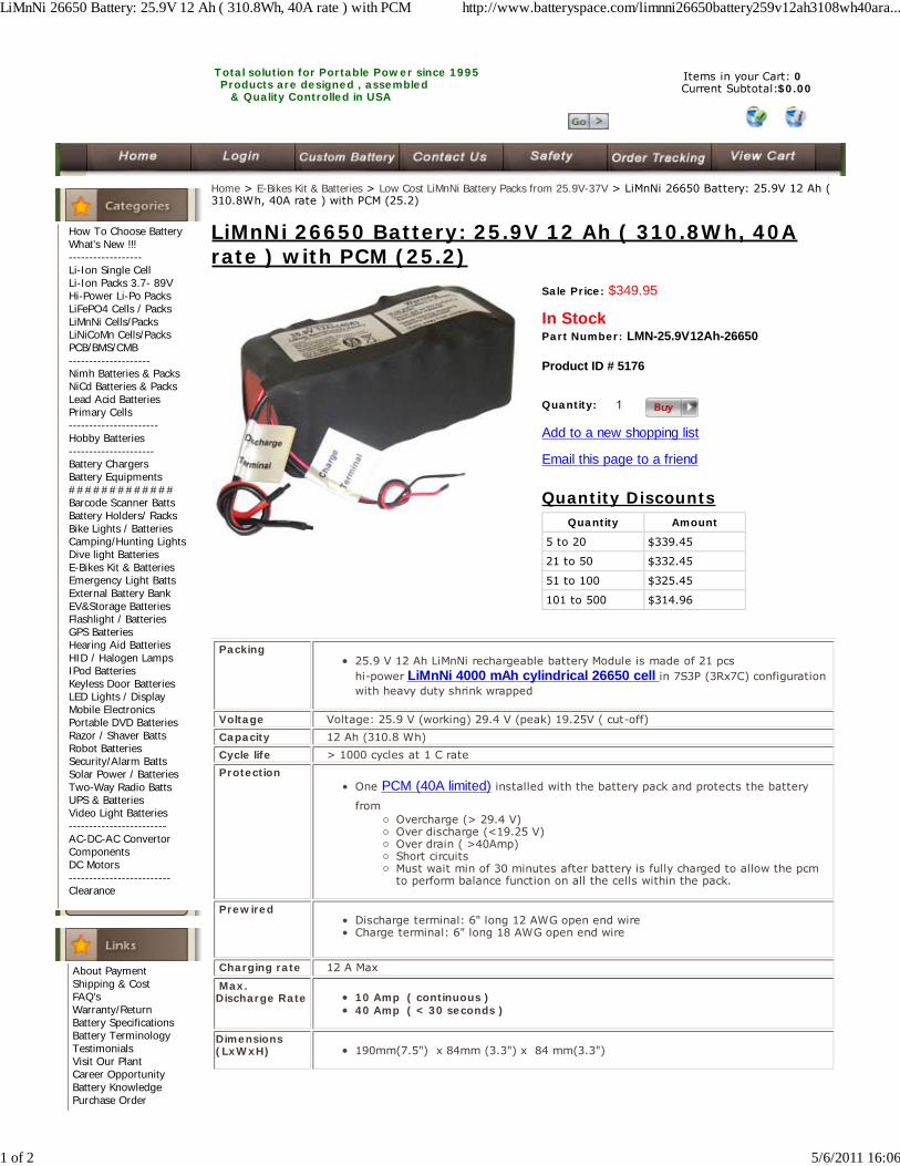
-LiMnNi Battery (25.9V, 12Ah). -Ti Case (w/ 316 SS hardware) -Two open-cell foam cushions for battery. -Purge Plug (2-013 o-ring, 2-010 o-ring).
Figure 1: Battery Case.
Setup Instructions: PMEL Real-Time Altimeter for Seabird 9/11 CTD
5
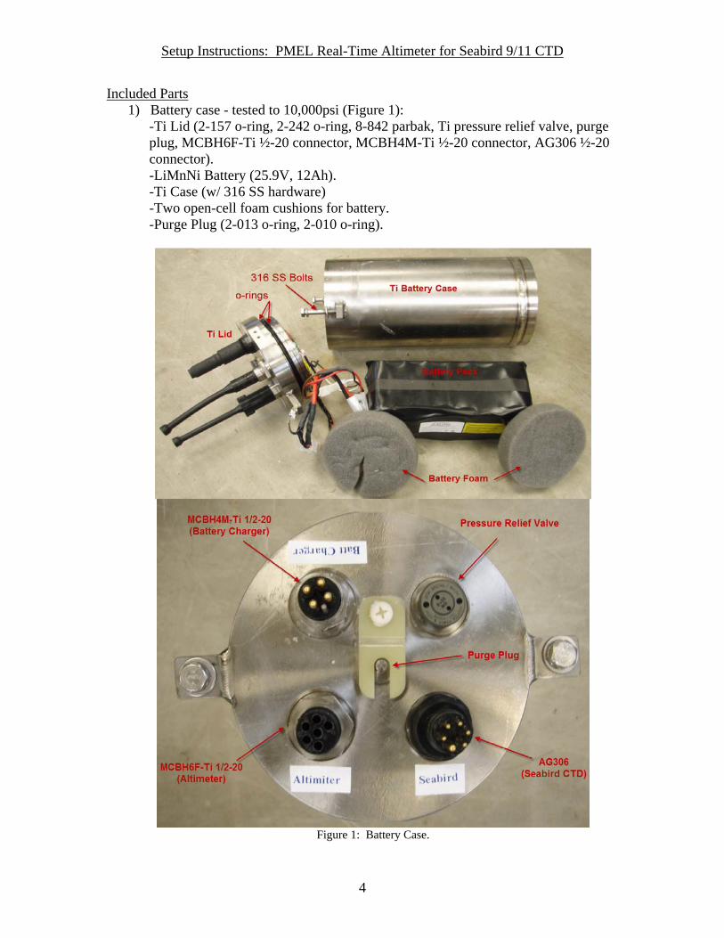
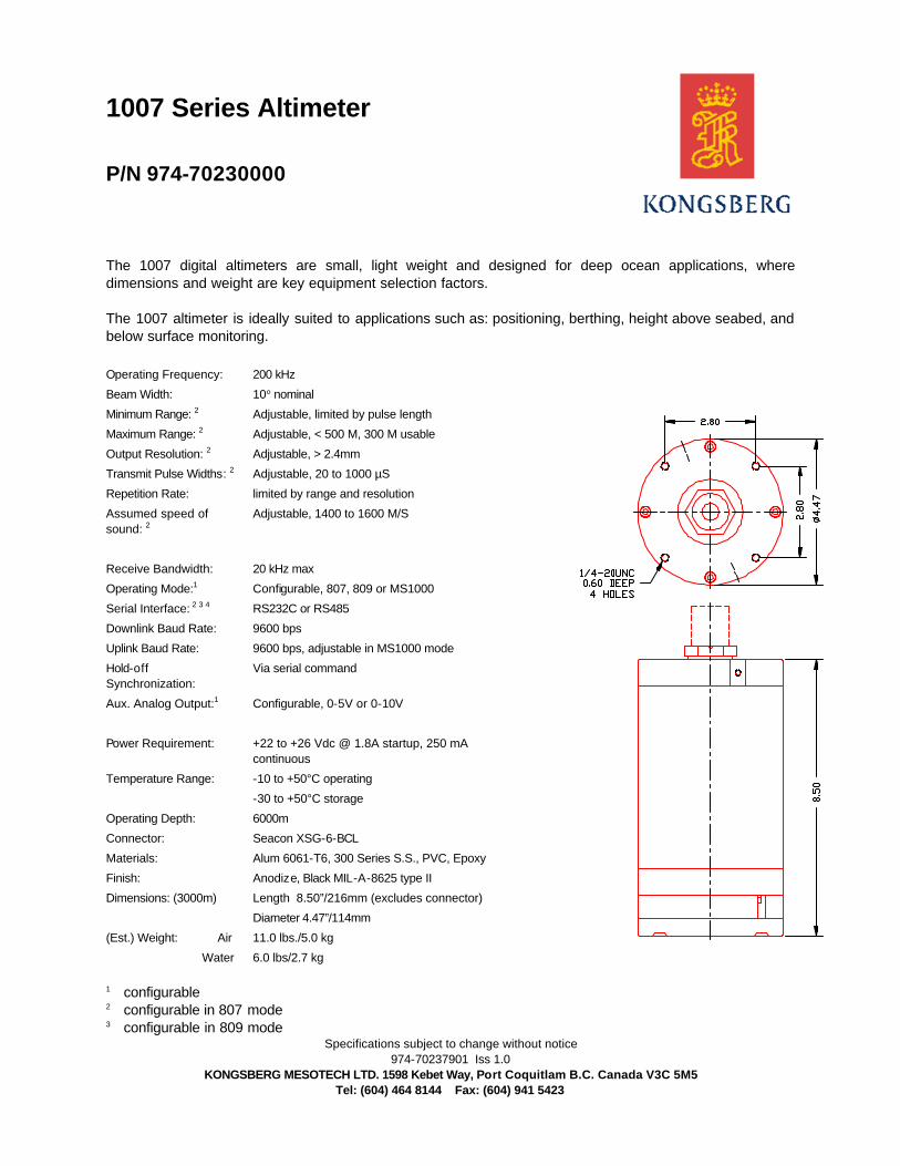
2) Kongsberg 1007 Altimeter – preconfigured (Figure 2).
Figure 2: Kongsberg 1007 Altimeter.
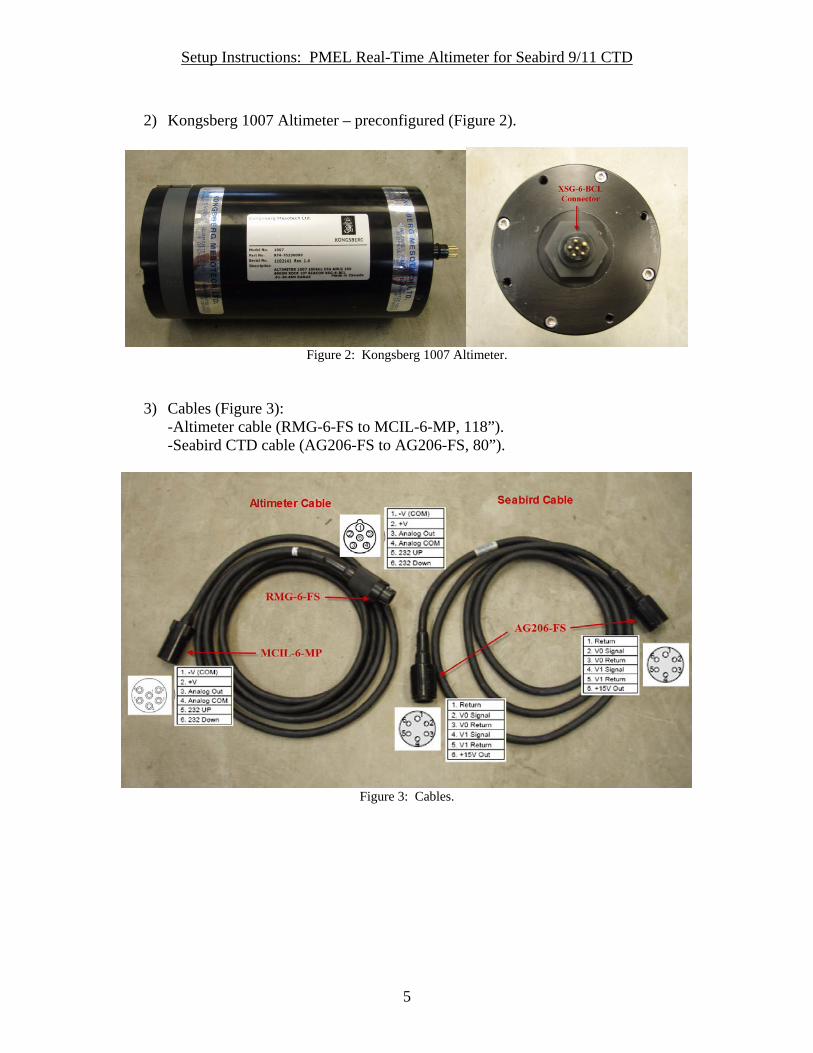
3) Cables (Figure 3): -Altimeter cable (RMG-6-FS to MCIL-6-MP, 118”). -Seabird CTD cable (AG206-FS to AG206-FS, 80”).
Figure 3: Cables.
Setup Instructions: PMEL Real-Time Altimeter for Seabird 9/11 CTD
6
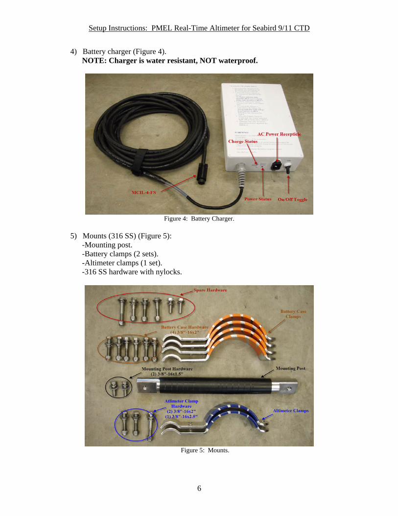
4) Battery charger (Figure 4). NOTE: Charger is water resistant, NOT waterproof.
Figure 4: Battery Charger.
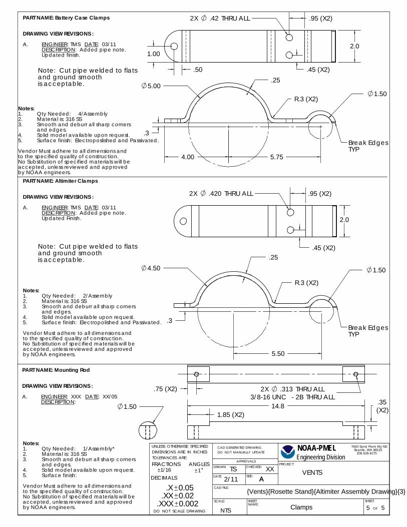
5) Mounts (316 SS) (Figure 5): -Mounting post. -Battery clamps (2 sets). -Altimeter clamps (1 set). -316 SS hardware with nylocks.
Figure 5: Mounts.
Setup Instructions: PMEL Real-Time Altimeter for Seabird 9/11 CTD
7
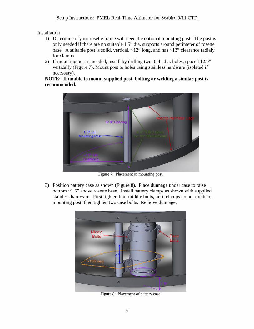
Installation 1) Determine if your rosette frame will need the optional mounting post. The post is
only needed if there are no suitable 1.5” dia. supports around perimeter of rosette base. A suitable post is solid, vertical, ~12” long, and has ~13” clearance radialy for clamps.
2) If mounting post is needed, install by drilling two, 0.4” dia. holes, spaced 12.9” vertically (Figure 7). Mount post to holes using stainless hardware (isolated if necessary).
NOTE: If unable to mount supplied post, bolting or welding a similar post is recommended.
Figure 7: Placement of mounting post.
3) Position battery case as shown (Figure 8). Place dunnage under case to raise
bottom ~1.5” above rosette base. Install battery clamps as shown with supplied stainless hardware. First tighten four middle bolts, until clamps do not rotate on mounting post, then tighten two case bolts. Remove dunnage.
Figure 8: Placement of battery case.
Setup Instructions: PMEL Real-Time Altimeter for Seabird 9/11 CTD
8
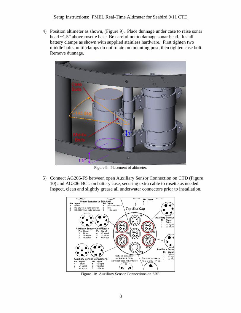
4) Position altimeter as shown, (Figure 9). Place dunnage under case to raise sonar head ~1.5” above rosette base. Be careful not to damage sonar head. Install battery clamps as shown with supplied stainless hardware. First tighten two middle bolts, until clamps do not rotate on mounting post, then tighten case bolt. Remove dunnage.
Figure 9: Placement of altimeter.
5) Connect AG206-FS between open Auxiliary Sensor Connection on CTD (Figure
10) and AG306-BCL on battery case, securing extra cable to rosette as needed. Inspect, clean and slightly grease all underwater connectors prior to installation.
Figure 10: Auxiliary Sensor Connections on SBE.

Setup Instructions: PMEL Real-Time Altimeter for Seabird 9/11 CTD
9
6) Connect MCIL-6-MP to MCBH6F-Ti connector on battery case. Route cable to altimeter, securing extra cable as needed. Inspect, clean and slightly grease all underwater connectors prior to installation. NOTE: Altimeter will start pinging as soon as it is connected. Only connect RMG-6-FS to XSG-6-BCL on altimeter when ready to deploy. Unplug and dummy off after use.

Setup Instructions: PMEL Real-Time Altimeter for Seabird 9/11 CTD
10
Charging Altimeter Battery 1) Verify the altimeter is disconnected from the battery case and dummy off the
XSG-6-BCL connector. 2) Connect battery charger to AC power (100-240VAC, 50-60Hz) and turn on the
charger via the On/OFF toggle switch (Figure 4 above). The Power Status light should illuminate red and the Charge Status should be green.
3) Connect the MCIL-4-FS battery charger cable to MCBH4M-Ti on battery case. When charger is connected to battery, the Charge Status light will turn red indicating unit is charging.
4) When Charge Status light turns green charging is complete. Charger will stop preventing overcharge of battery. If light does not turn green, battery may be faulty.
5) Chargers may get warm during normal charging. NOTE: Always place the charger in well-ventilated, dry environment and indoor use only. Connect AC power (step 2) BEFORE connecting to battery (step 3), otherwise system will not charge. Charger will turn off if not connected to battery for more than three minutes (cycle power, via AC plug, to reset). Battery will take approximately 5-6 hours to charge depending on level of depletion. A fully charged battery will last for approximately 50 hours.
Setup Instructions: PMEL Real-Time Altimeter for Seabird 9/11 CTD
11
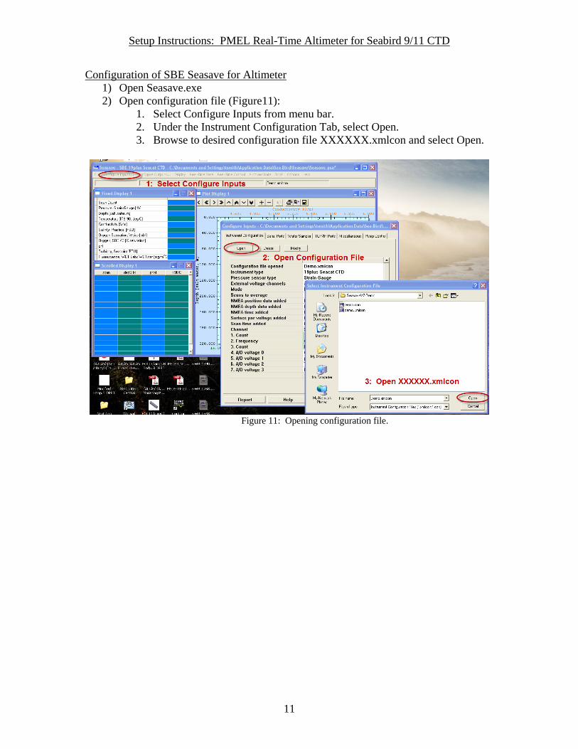
Configuration of SBE Seasave for Altimeter 1) Open Seasave.exe 2) Open configuration file (Figure11):
1. Select Configure Inputs from menu bar. 2. Under the Instrument Configuration Tab, select Open. 3. Browse to desired configuration file XXXXXX.xmlcon and select Open.
Figure 11: Opening configuration file.
Setup Instructions: PMEL Real-Time Altimeter for Seabird 9/11 CTD
12
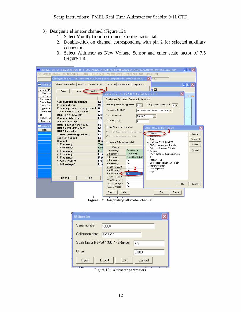
3) Designate altimeter channel (Figure 12): 1. Select Modify from Instrument Configuration tab. 2. Double-click on channel corresponding with pin 2 for selected auxiliary
connector. 3. Select Altimeter as New Voltage Sensor and enter scale factor of 7.5
(Figure 13).
Figure 12: Designating altimeter channel.
Figure 13: Altimeter parameters.

Setup Instructions: PMEL Real-Time Altimeter for Seabird 9/11 CTD
13
4. Exit and Save. NOTE: On deck or in waters greater than 200m (no signal return), altimeter will read full depth (200m). A depleted battery will cause altimeter to return 0m.

Setup Instructions: PMEL Real-Time Altimeter for Seabird 9/11 CTD
14
Additional Info/Notes
• Kongsberg 1007 Altimeter settings have been pre-configured. Do not attempt to alter settings without first consulting PMEL/EDD.
• Altimeter and Battery cases have been pre-wrapped with polymer adhesive for isolation.
• Installation described above is suggested layout. Modifications are possible with consultation from PMEL/EDD.
• Engineering drawings for battery case and mounts can be found in Appendix A • Specs for Altimeter and battery (MSDS), battery charger, and pressure relief
valve (set to 10psi) can be found in Appendix B. • For reference (not to be used without consulting PMEL/EDD), the configuration
manual for the Kongsberg 1007 Series Altimeters is included in Appendix C.

Setup Instructions: PMEL Real-Time Altimeter for Seabird 9/11 CTD
15
APPENDIX

Setup Instructions: PMEL Real-Time Altimeter for Seabird 9/11 CTD
16
APPENDIX A
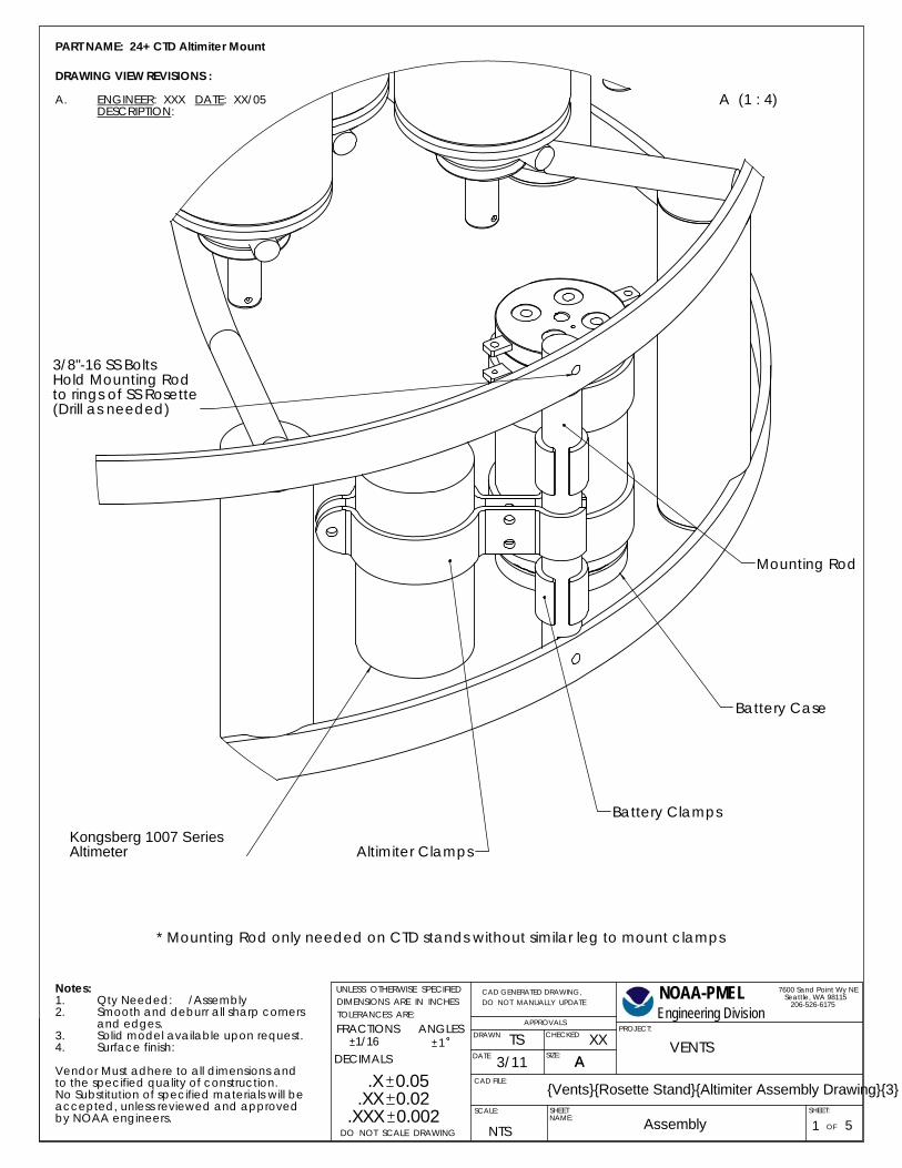
PART NAME: 24+ CTD Altimiter Mount
DRAWING VIEW REVISIONS :
ENGINEER: XXX DATE: XX/05A.DESCRIPTION:
Notes:Qty Needed: /Assembly1.Smooth and deburr all sharp corners2.and edges.Solid model available upon request.3.Surface finish:4.
Vendor Must adhere to all dimensions andto the specified quality of construction.No Substitution of specified materials will beaccepted, unless reviewed and approved by NOAA engineers.
Mounting Rod
A (1 : 4)
Kongsberg 1007 Series Altimeter Altimiter Clamps
Battery Clamps
Battery Case
3/8"-16 SS BoltsHold Mounting Rodto rings of SS Rosette(Drill as needed)
* Mounting Rod only needed on CTD stands without similar leg to mount clamps
PROJECT:
AssemblySHEETNAME:
DECIMALS1
Engineering Division
7600 Sand Point Wy NE Seattle, WA 98115 206-526-6175
NTS
{Vents}{Rosette Stand}{Altimiter Assembly Drawing}{3}
1DO NOT SCALE DRAWING
.X 0.05.XX 0.02
.XXX 0.002
1/16FRACTIONS ANGLESTOLERANCES ARE:DIMENSIONS ARE IN INCHESUNLESS OTHERWISE SPECIFIED
CHECKEDDRAWN
DATE
OF
SHEET:
CAD FILE:
SIZE:
SCALE:
DO NOT MANUALLY UPDATECAD GENERATED DRAWING, NOAA-PMEL
5
APPROVALS
AVENTS
3/11XX
ATS
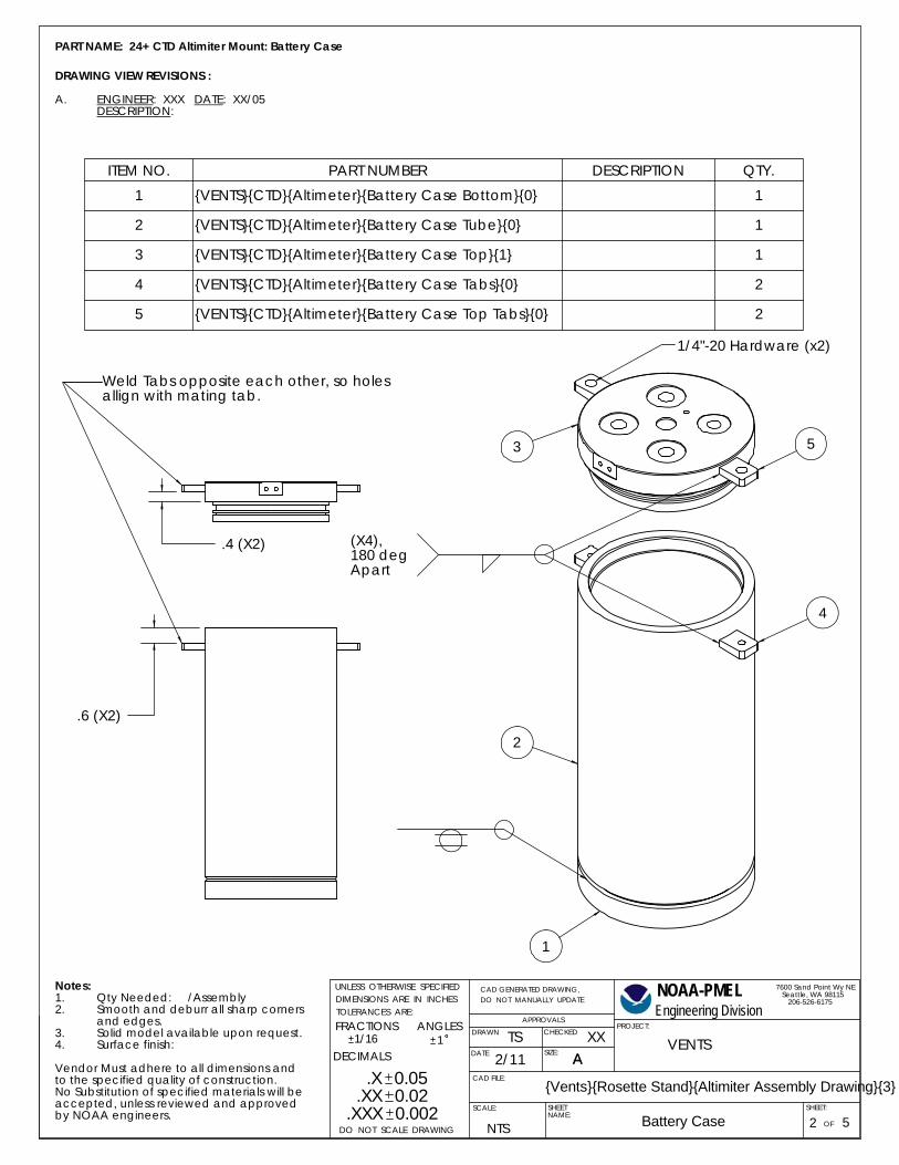
Weld Tabs opposite each other, so holes allign with mating tab.
.6 (X2)
.4 (X2)
1
2
4
53
1/4"-20 Hardware (x2)
(X4),180 deg Apart
PROJECT:
Battery CaseSHEETNAME:
DECIMALS1
Engineering Division
7600 Sand Point Wy NE Seattle, WA 98115 206-526-6175
NTS
{Vents}{Rosette Stand}{Altimiter Assembly Drawing}{3}
2DO NOT SCALE DRAWING
.X 0.05.XX 0.02
.XXX 0.002
1/16FRACTIONS ANGLESTOLERANCES ARE:DIMENSIONS ARE IN INCHESUNLESS OTHERWISE SPECIFIED
CHECKEDDRAWN
DATE
OF
SHEET:
CAD FILE:
SIZE:
SCALE:
DO NOT MANUALLY UPDATECAD GENERATED DRAWING, NOAA-PMEL
5
APPROVALS
AVENTS
2/11XX
ATS
PART NAME: 24+ CTD Altimiter Mount: Battery Case
DRAWING VIEW REVISIONS :
ENGINEER: XXX DATE: XX/05A.DESCRIPTION:
Notes:Qty Needed: /Assembly1.Smooth and deburr all sharp corners2.and edges.Solid model available upon request.3.Surface finish:4.
Vendor Must adhere to all dimensions andto the specified quality of construction.No Substitution of specified materials will beaccepted, unless reviewed and approved by NOAA engineers.
ITEM NO. PART NUMBER DESCRIPTION QTY.1 {VENTS}{CTD}{Altimeter}{Battery Case Bottom}{0} 1
2 {VENTS}{CTD}{Altimeter}{Battery Case Tube}{0} 1
3 {VENTS}{CTD}{Altimeter}{Battery Case Top}{1} 1
4 {VENTS}{CTD}{Altimeter}{Battery Case Tabs}{0} 2
5 {VENTS}{CTD}{Altimeter}{Battery Case Top Tabs}{0} 2
32
A-A (1 : 4)
32
4.3774.375
9.5
15°
.06
.45
CHAMFER .08 45° X
4.30
.800
.040 4.12
CHAMFER .08 45° X
(X4, Evenly spaced on 4.00 BCD)1/4-20 UNC - 2B .350
4X .201 .600
5.0
1/4-20 UNC - 2B THRU ALL .201 THRU ALL
R.1(X2)
.35
.35
R2.5
.9
.25
.7
5.0
AA
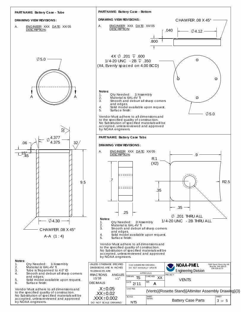
PART NAME: Battery Case - Tube
DRAWING VIEW REVISIONS :
ENGINEER: XXX DATE: XX/05A.DESCRIPTION:
Notes:Qty Needed: 1/Assembly1.Material is: 6AL-4V Ti2.Tube is Trepanned to 4.0" ID3.Smooth and deburr all sharp corners4.and edges.Solid model available upon request.5.Surface finish:6.
Vendor Must adhere to all dimensions andto the specified quality of construction.No Substitution of specified materials will beaccepted, unless reviewed and approved by NOAA engineers.
Notes:Qty Needed: 1/Assembly1.Material is: 6AL-4V Ti2.Smooth and deburr all sharp corners3.and edges.Solid model available upon request.4.Surface finish:5.
Vendor Must adhere to all dimensions andto the specified quality of construction.No Substitution of specified materials will beaccepted, unless reviewed and approved by NOAA engineers.
PART NAME: Battery Case - Bottom
DRAWING VIEW REVISIONS :
ENGINEER: XXX DATE: XX/05A.DESCRIPTION:
PART NAME: Battery Case Tabs
DRAWING VIEW REVISIONS :
ENGINEER: XXX DATE: XX/05A.DESCRIPTION:
Notes:Qty Needed: 2/Assembly1.Material is: 6AL-4V Ti2.Smooth and deburr all sharp corners3.and edges.Solid model available upon request.4.Surface finish:5.
Vendor Must adhere to all dimensions andto the specified quality of construction.No Substitution of specified materials will beaccepted, unless reviewed and approved by NOAA engineers.
PROJECT:
Battery Case PartsSHEETNAME:
DECIMALS1
Engineering Division
7600 Sand Point Wy NE Seattle, WA 98115 206-526-6175
NTS
{Vents}{Rosette Stand}{Altimiter Assembly Drawing}{3}
3DO NOT SCALE DRAWING
.X 0.05.XX 0.02
.XXX 0.002
1/16FRACTIONS ANGLESTOLERANCES ARE:DIMENSIONS ARE IN INCHESUNLESS OTHERWISE SPECIFIED
CHECKEDDRAWN
DATE
OF
SHEET:
CAD FILE:
SIZE:
SCALE:
DO NOT MANUALLY UPDATECAD GENERATED DRAWING, NOAA-PMEL
5
APPROVALS
AVENTS
2/11XX
ATS
45°45°
90°
B (1 : 1).250 TYP .19 TYP
8-32 UNC - 2B .52X .136 .7
4X .323 THRU ALL
.423 X 90°4X .323 THRU ALL
180 APART on 3.60 BCD1/4-20 UNC - 2B .250
2X .201 .400
180 APART on 2.00 BCD1/4-20 UNC - 2B .250
2X .201 .400
A
A
2-157
C (2 : 1)
2-242B 8-842
.142
.136
.083
.081
.215
.208
.115
.112
.25
C
A-A (1 : 2)
4.3724.370
4.541
.50
.040
.75
.85
1.14
1.50
.10
3.90
CHAMFER .05 15° X
CHAMFER .05 (X2)45° X B B5.0
on 2.70 BCDSpotface .95 .03
7/16-20 UNF - 2B .6 .391 1.0
(X3, 90 APART on 2.70 BCD)Spotface 1.10 .03
1/2-20 UNF 1.03X .453 1.3
on 1.60 BCD10-32 UNF - 2B .5
.159 .7
.562±.001 .64 .13 THRU ALL
PROJECT:
Battery Case Parts (2)SHEETNAME:
DECIMALS1
Engineering Division
7600 Sand Point Wy NE Seattle, WA 98115 206-526-6175
NTS
{Vents}{Rosette Stand}{Altimiter Assembly Drawing}{3}
4DO NOT SCALE DRAWING
.X 0.05.XX 0.02
.XXX 0.002
1/16FRACTIONS ANGLESTOLERANCES ARE:DIMENSIONS ARE IN INCHESUNLESS OTHERWISE SPECIFIED
CHECKEDDRAWN
DATE
OF
SHEET:
CAD FILE:
SIZE:
SCALE:
DO NOT MANUALLY UPDATECAD GENERATED DRAWING, NOAA-PMEL
5
APPROVALS
AVENTS
2/11XX
ATS
.9
.7
.35
.35
R.1 (X2)
R2.5
.32 THRU ALL
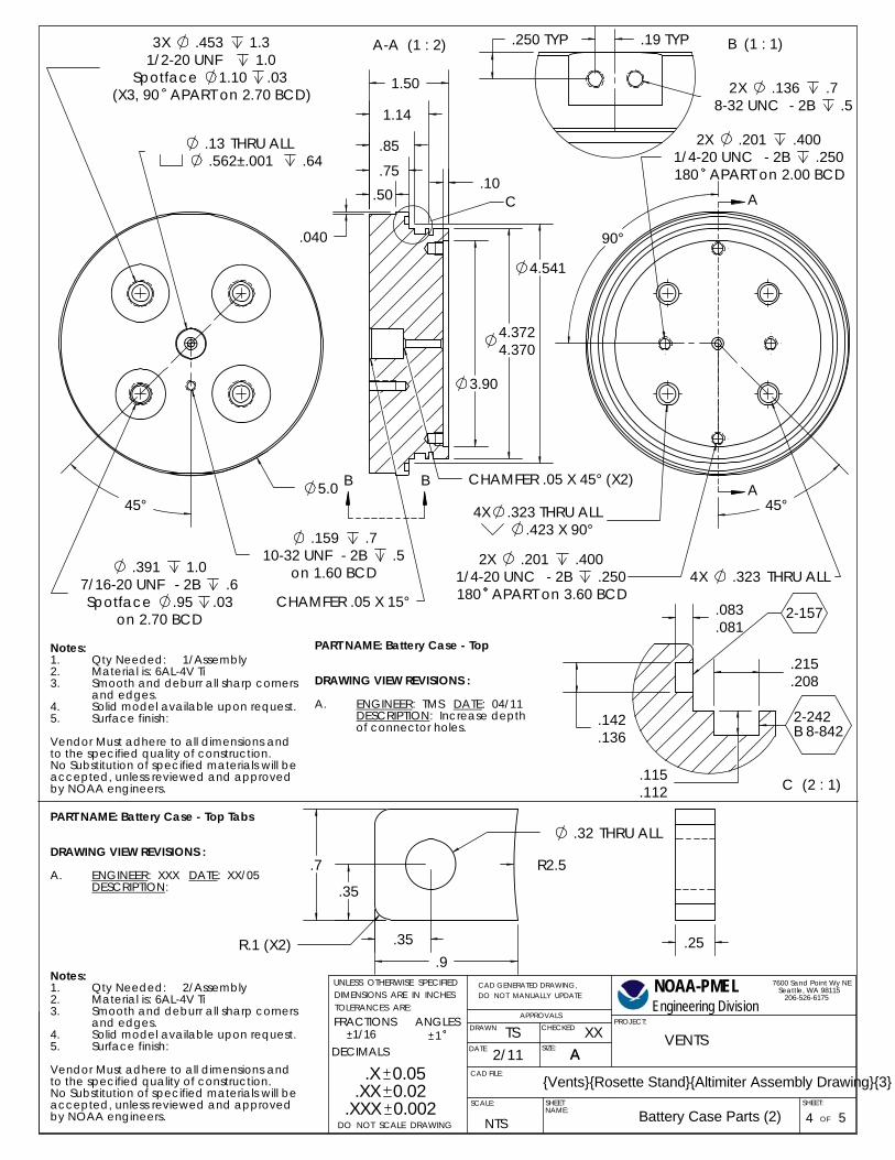
Notes:Qty Needed: 1/Assembly1.Material is: 6AL-4V Ti2.Smooth and deburr all sharp corners3.and edges.Solid model available upon request.4.Surface finish:5.
Vendor Must adhere to all dimensions andto the specified quality of construction.No Substitution of specified materials will beaccepted, unless reviewed and approved by NOAA engineers.
PART NAME: Battery Case - Top
DRAWING VIEW REVISIONS :
ENGINEER: TMS DATE: 04/11A.DESCRIPTION: Increase depth of connector holes.
PART NAME: Battery Case - Top Tabs
DRAWING VIEW REVISIONS :
ENGINEER: XXX DATE: XX/05A.DESCRIPTION:
Notes:Qty Needed: 2/Assembly1.Material is: 6AL-4V Ti2.Smooth and deburr all sharp corners3.and edges.Solid model available upon request.4.Surface finish:5.
Vendor Must adhere to all dimensions andto the specified quality of construction.No Substitution of specified materials will beaccepted, unless reviewed and approved by NOAA engineers.
.3
5.50
5.75
.3
4.00
Break EdgesTYP
4.50 1.50
.25
R.3 (X2)
Break EdgesTYP
R.3 (X2)
.255.00
1.50
2.0
.95 (X2)
.45 (X2)
2X .42 THRU ALL
.50
1.00
2.0
.95 (X2)
.45 (X2)
2X .420 THRU ALL
Notes:Qty Needed: 4/Assembly1.Material is: 316 SS2.Smooth and deburr all sharp corners3.and edges.Solid model available upon request.4.Surface finish: Electroposlished and Passivated.5.
Vendor Must adhere to all dimensions andto the specified quality of construction.No Substitution of specified materials will beaccepted, unless reviewed and approved by NOAA engineers.
PART NAME: Battery Case Clamps
DRAWING VIEW REVISIONS :
ENGINEER: TMS DATE: 03/11A.DESCRIPTION: Added pipe note.Updated finish.
PART NAME: Mounting Rod
DRAWING VIEW REVISIONS :
ENGINEER: XXX DATE: XX/05A.DESCRIPTION:
Notes:Qty Needed: 1/Assembly*1.Material is: 316 SS2.Smooth and deburr all sharp corners3.and edges.Solid model available upon request.4.Surface finish:5.
Vendor Must adhere to all dimensions andto the specified quality of construction.No Substitution of specified materials will beaccepted, unless reviewed and approved by NOAA engineers.
Notes:Qty Needed: 2/Assembly1.Material is: 316 SS2.Smooth and deburr all sharp corners3.and edges.Solid model available upon request.4.Surface finish: Electropolished and Passivated.5.
Vendor Must adhere to all dimensions andto the specified quality of construction.No Substitution of specified materials will beaccepted, unless reviewed and approved by NOAA engineers.
Note: Cut pipe welded to flats and ground smoothis acceptable.
Note: Cut pipe welded to flats and ground smoothis acceptable.
PART NAME: Altimiter Clamps
DRAWING VIEW REVISIONS :
ENGINEER: TMS DATE: 03/11A.DESCRIPTION: Added pipe note.Updated Finish.
1.501.85 (X2)
14.8 .35(X2)
.75 (X2)3/8-16 UNC - 2B THRU ALL
2X .313 THRU ALL
PROJECT:
ClampsSHEETNAME:
DECIMALS1
Engineering Division
7600 Sand Point Wy NE Seattle, WA 98115 206-526-6175
NTS
{Vents}{Rosette Stand}{Altimiter Assembly Drawing}{3}
5DO NOT SCALE DRAWING
.X 0.05.XX 0.02
.XXX 0.002
1/16FRACTIONS ANGLESTOLERANCES ARE:DIMENSIONS ARE IN INCHESUNLESS OTHERWISE SPECIFIED
CHECKEDDRAWN
DATE
OF
SHEET:
CAD FILE:
SIZE:
SCALE:
DO NOT MANUALLY UPDATECAD GENERATED DRAWING, NOAA-PMEL
5
APPROVALS
AVENTS
2/11XX
ATS

Setup Instructions: PMEL Real-Time Altimeter for Seabird 9/11 CTD
17
APPENDIX B
Specifications subject to change without notice 974-70237901 Iss 1.0
KONGSBERG MESOTECH LTD. 1598 Kebet Way, Port Coquitlam B.C. Canada V3C 5M5 Tel: (604) 464 8144 Fax: (604) 941 5423
1007 Series Altimeter P/N 974-70230000 The 1007 digital altimeters are small, light weight and designed for deep ocean applications, where dimensions and weight are key equipment selection factors. The 1007 altimeter is ideally suited to applications such as: positioning, berthing, height above seabed, and below surface monitoring. Operating Frequency: 200 kHz
Beam Width: 10° nominal
Minimum Range: 2 Adjustable, limited by pulse length
Maximum Range: 2 Adjustable, < 500 M, 300 M usable
Output Resolution: 2 Adjustable, > 2.4mm
Transmit Pulse Widths: 2 Adjustable, 20 to 1000 µS
Repetition Rate: limited by range and resolution
Assumed speed of sound: 2
Adjustable, 1400 to 1600 M/S
Receive Bandwidth: 20 kHz max
Operating Mode:1 Configurable, 807, 809 or MS1000
Serial Interface: 2 3 4 RS232C or RS485
Downlink Baud Rate: 9600 bps
Uplink Baud Rate: 9600 bps, adjustable in MS1000 mode
Hold-off Synchronization:
Via serial command
Aux. Analog Output:1 Configurable, 0-5V or 0-10V
Power Requirement: +22 to +26 Vdc @ 1.8A startup, 250 mA continuous
Temperature Range: -10 to +50°C operating
-30 to +50°C storage
Operating Depth: 6000m
Connector: Seacon XSG-6-BCL
Materials: Alum 6061-T6, 300 Series S.S., PVC, Epoxy
Finish: Anodize, Black MIL-A-8625 type II
Dimensions: (3000m) Length 8.50”/216mm (excludes connector)
Diameter 4.47”/114mm
(Est.) Weight: Air 11.0 lbs./5.0 kg
Water 6.0 lbs/2.7 kg 1 configurable 2 configurable in 807 mode 3 configurable in 809 mode

Specifications subject to change without notice 974-70237901 Iss 1.0
KONGSBERG MESOTECH LTD. 1598 Kebet Way, Port Coquitlam B.C. Canada V3C 5M5 Tel: (604) 464 8144 Fax: (604) 941 5423
4 auto-detect in MS1000 mode • configurable settings require ALTCONFIG software
Total solution for Portable Power since 1995 Products are designed , assembled & Quality Controlled in USA
Items in your Cart: 0 Current Subtotal:$0.00
How To Choose BatteryWhat's New !!!------------------Li-Ion Single CellLi-Ion Packs 3.7- 89VHi-Power Li-Po PacksLiFePO4 Cells / PacksLiMnNi Cells/PacksLiNiCoMn Cells/PacksPCB/BMS/CMB--------------------Nimh Batteries & PacksNiCd Batteries & PacksLead Acid BatteriesPrimary Cells----------------------Hobby Batteries---------------------Battery ChargersBattery Equipments#############Barcode Scanner BattsBattery Holders/ RacksBike Lights / BatteriesCamping/Hunting LightsDive light BatteriesE-Bikes Kit & BatteriesEmergency Light BattsExternal Battery BankEV&Storage BatteriesFlashlight / BatteriesGPS BatteriesHearing Aid BatteriesHID / Halogen LampsIPod BatteriesKeyless Door BatteriesLED Lights / DisplayMobile ElectronicsPortable DVD BatteriesRazor / Shaver BattsRobot BatteriesSecurity/Alarm BattsSolar Power / BatteriesTwo-Way Radio BattsUPS & BatteriesVideo Light Batteries------------------------AC-DC-AC ConvertorComponentsDC Motors-------------------------Clearance
About Payment Shipping & Cost FAQ's Warranty/Return Battery Specifications Battery Terminology Testimonials Visit Our Plant Career Opportunity Battery Knowledge Purchase Order
Home > E-Bikes Kit & Batteries > Low Cost LiMnNi Battery Packs from 25.9V-37V > LiMnNi 26650 Battery: 25.9V 12 Ah (310.8Wh, 40A rate ) with PCM (25.2)
LiMnNi 26650 Battery: 25.9V 12 Ah ( 310.8Wh, 40Arate ) with PCM (25.2)
Sale Price: $349.95
In StockPart Number: LMN-25.9V12Ah-26650
Product ID # 5176
Quantity:
Add to a new shopping list
Email this page to a friend
Quantity DiscountsQuantity Amount
5 to 20 $339.45
21 to 50 $332.45
51 to 100 $325.45
101 to 500 $314.96
Packing25.9 V 12 Ah LiMnNi rechargeable battery Module is made of 21 pcshi-power LiMnNi 4000 mAh cylindrical 26650 cell in 7S3P (3Rx7C) configurationwith heavy duty shrink wrapped
Voltage Voltage: 25.9 V (working) 29.4 V (peak) 19.25V ( cut-off) Capacity 12 Ah (310.8 Wh) Cycle life > 1000 cycles at 1 C rate Protection
One PCM (40A limited) installed with the battery pack and protects the battery
fromOvercharge (> 29.4 V)Over discharge (<19.25 V)Over drain ( >40Amp)Short circuitsMust wait min of 30 minutes after battery is fully charged to allow the pcmto perform balance function on all the cells within the pack.
PrewiredDischarge terminal: 6" long 12 AWG open end wire Charge terminal: 6" long 18 AWG open end wire
Charging rate 12 A Max Max.Discharge Rate 10 Amp ( continuous )
40 Amp ( < 30 seconds )
Dimensions(LxWxH) 190mm(7.5") x 84mm (3.3") x 84 mm(3.3")
LiMnNi 26650 Battery: 25.9V 12 Ah ( 310.8Wh, 40A rate ) with PCM http://www.batteryspace.com/limnni26650battery259v12ah3108wh40ara...
1 of 2 5/6/2011 16:06
Privacy Policy Export restrictions
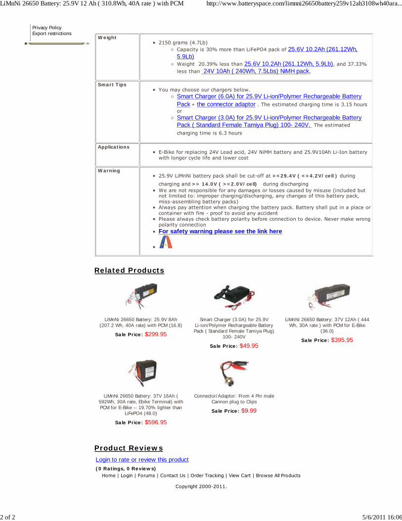
Weight2150 grams (4.7Lb)
Capacity is 30% more than LiFePO4 pack of 25.6V 10.2Ah (261.12Wh,5.9Lb)Weight 20.39% less than 25.6V 10.2Ah (261.12Wh, 5.9Lb), and 37.33%less than 24V 10Ah ( 240Wh, 7.5Lbs) NiMH pack,
Smart TipsYou may choose our chargers below.
Smart Charger (6.0A) for 25.9V Li-ion/Polymer Rechargeable BatteryPack + the connector adaptor . The estimated charging time is 3.15 hoursorSmart Charger (3.0A) for 25.9V Li-ion/Polymer Rechargeable BatteryPack ( Standard Female Tamiya Plug) 100- 240V. The estimatedcharging time is 6.3 hours
ApplicationsE-Bike for replacing 24V Lead acid, 24V NiMH battery and 25.9V10Ah Li-Ion batterywith longer cycle life and lower cost
Warning25.9V LiMnNi battery pack shall be cut-off at =<29.4V ( <=4.2V/cell ) duringcharging and >= 14.0V ( >=2.0V/cell) during discharging We are not responsible for any damages or losses caused by misuse (included butnot limited to: improper charging/discharging, any changes of this battery pack,miss-assembling battery packs)Always pay attention when charging the battery pack. Battery shall put in a place orcontainer with fire - proof to avoid any accidentPlease always check battery polarity before connection to device. Never make wrongpolarity connectionFor safety warning please see the link here
Related Products
LiMnNi 26650 Battery: 25.9V 8Ah(207.2 Wh, 40A rate) with PCM (16.8)
Sale Price: $299.95
Smart Charger (3.0A) for 25.9VLi-ion/Polymer Rechargeable BatteryPack ( Standard Female Tamiya Plug)
100- 240V
Sale Price: $49.95
LiMnNi 26650 Battery: 37V 12Ah ( 444Wh, 30A rate ) with PCM for E-Bike
(36.0)
Sale Price: $395.95
LiMnNi 26650 Battery: 37V 16Ah (592Wh, 30A rate, Ebike Terminal) withPCM for E-Bike -- 19.70% lighter than
LiFePO4 (48.0)
Sale Price: $596.95
Connector/Adaptor: From 4 Pin maleCannon plug to Clips
Sale Price: $9.99
Product ReviewsLogin to rate or review this product(0 Ratings, 0 Reviews)
Home | Login | Forums | Contact Us | Order Tracking | View Cart | Browse All Products
Copyright 2000-2011.
LiMnNi 26650 Battery: 25.9V 12 Ah ( 310.8Wh, 40A rate ) with PCM http://www.batteryspace.com/limnni26650battery259v12ah3108wh40ara...
2 of 2 5/6/2011 16:06

Report No.: 0905272-231 Report Date: 2009-06-04
MSDS Report
+Material Safety Data Sheet+Material Safety Data Sheet+Material Safety Data Sheet+Material Safety Data Sheet
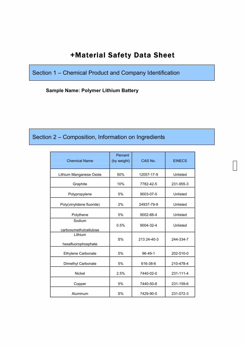
Sample Name: Polymer Lithium Battery
Chemical Name
Percent
(by weight)
CAS No.
EINECS
Lithium Manganese Oxide 50% 12057-17-9 Unlisted
Graphite 10% 7782-42-5 231-955-3
Polypropylene 5% 9003-07-0 Unlisted
Poly(vinylidene fluoride) 2% 24937-79-9 Unlisted
Polythene 5% 9002-88-4 Unlisted
Sodium
carboxymethylcellulose
0.5%
9004-32-4
Unlisted
Lithium
hexafluorophosphate
S%
213 24-40-3
244-334-7
Ethylene Carbonate 5% 96-49-1 202-510-0
Dimethyl Carbonate 5% 616-38-6 210-478-4
Nickel 2.5% 7440-02-0 231-111-4
Copper 5% 7440-50-8 231-159-6
Aluminum S% 7429-90-5 231-072-3
Section 1 – Chemical Product and Company Identification
Section 2 – Composition, Information on Ingredients
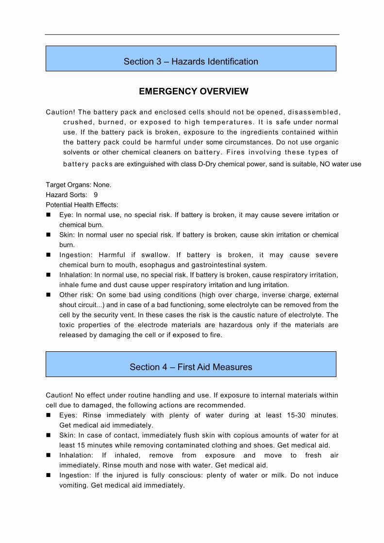
EMERGENCY OVERVIEW
Caution! The battery pack and enclosed cells should not be opened, d isassembled,
c rushed, burned, or exposed to h igh temperatures. I t i s safe under normal
use. If the battery pack is broken, exposure to the ingredients contained within
the battery pack could be harmful under some circumstances. Do not use organic
solvents or other chemical cleaners on bat tery. F i res involv ing these types of
bat tery packs are extinguished with class D-Dry chemical power, sand is suitable, NO water use
Target Organs: None.
Hazard Sorts: 9
Potential Health Effects:
� Eye: In normal use, no special risk. If battery is broken, it may cause severe irritation or
chemical burn.
� Skin: In normal user no special risk. If battery is broken, cause skin irritation or chemical
burn.
� Ingestion: Harmful if swallow. If battery is broken, it may cause severe
chemical burn to mouth, esophagus and gastrointestinal system.
� Inhalation: In normal use, no special risk. If battery is broken, cause respiratory irritation,
inhale fume and dust cause upper respiratory irritation and lung irritation.
� Other risk: On some bad using conditions (high over charge, inverse charge, external
shout circuit...) and in case of a bad functioning, some electrolyte can be removed from the
cell by the security vent. In these cases the risk is the caustic nature of electrolyte. The
toxic properties of the electrode materials are hazardous only if the materials are
released by damaging the cell or if exposed to fire.
Caution! No effect under routine handling and use. If exposure to internal materials within
cell due to damaged, the following actions are recommended.
� Eyes: Rinse immediately with plenty of water during at least 15-30 minutes.
Get medical aid immediately.
� Skin: In case of contact, immediately flush skin with copious amounts of water for at
least 15 minutes while removing contaminated clothing and shoes. Get medical aid.
� Inhalation: If inhaled, remove from exposure and move to fresh air
immediately. Rinse mouth and nose with water. Get medical aid.
� Ingestion: If the injured is fully conscious: plenty of water or milk. Do not induce
vomiting. Get medical aid immediately.
Section 3 – Hazards Identification
Section 4 – First Aid Measures
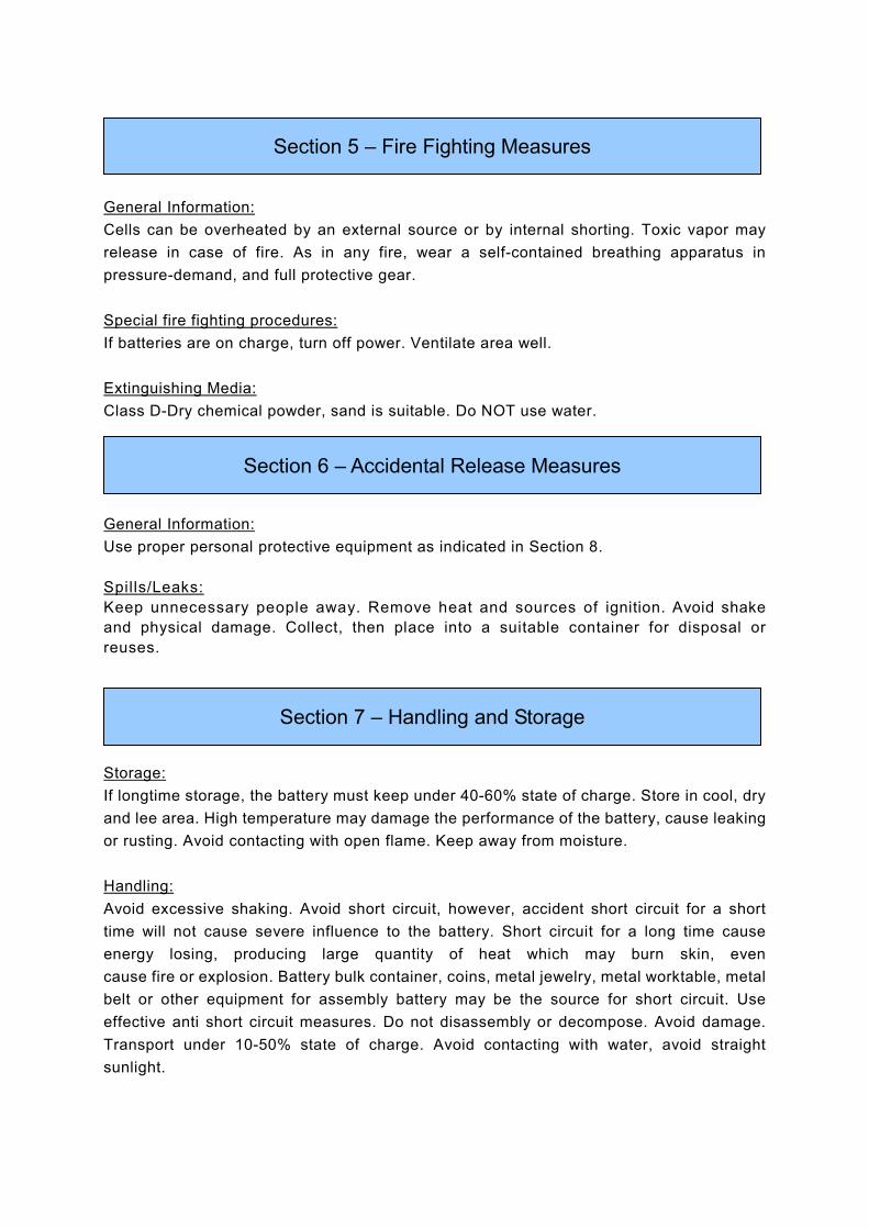
General Information:
Cells can be overheated by an external source or by internal shorting. Toxic vapor may
release in case of fire. As in any fire, wear a self-contained breathing apparatus in
pressure-demand, and full protective gear.
Special fire fighting procedures:
If batteries are on charge, turn off power. Ventilate area well.
Extinguishing Media:
Class D-Dry chemical powder, sand is suitable. Do NOT use water.
General Information:
Use proper personal protective equipment as indicated in Section 8.
Spills/Leaks:
Keep unnecessary people away. Remove heat and sources of ignition. Avoid shake
and physical damage. Collect, then place into a suitable container for disposal or
reuses.
Storage:
If longtime storage, the battery must keep under 40-60% state of charge. Store in cool, dry
and lee area. High temperature may damage the performance of the battery, cause leaking
or rusting. Avoid contacting with open flame. Keep away from moisture.
Handling:
Avoid excessive shaking. Avoid short circuit, however, accident short circuit for a short
time will not cause severe influence to the battery. Short circuit for a long time cause
energy losing, producing large quantity of heat which may burn skin, even
cause fire or explosion. Battery bulk container, coins, metal jewelry, metal worktable, metal
belt or other equipment for assembly battery may be the source for short circuit. Use
effective anti short circuit measures. Do not disassembly or decompose. Avoid damage.
Transport under 10-50% state of charge. Avoid contacting with water, avoid straight
sunlight.
Section 5 – Fire Fighting Measures
Section 6 – Accidental Release Measures
Section 7 – Handling and Storage
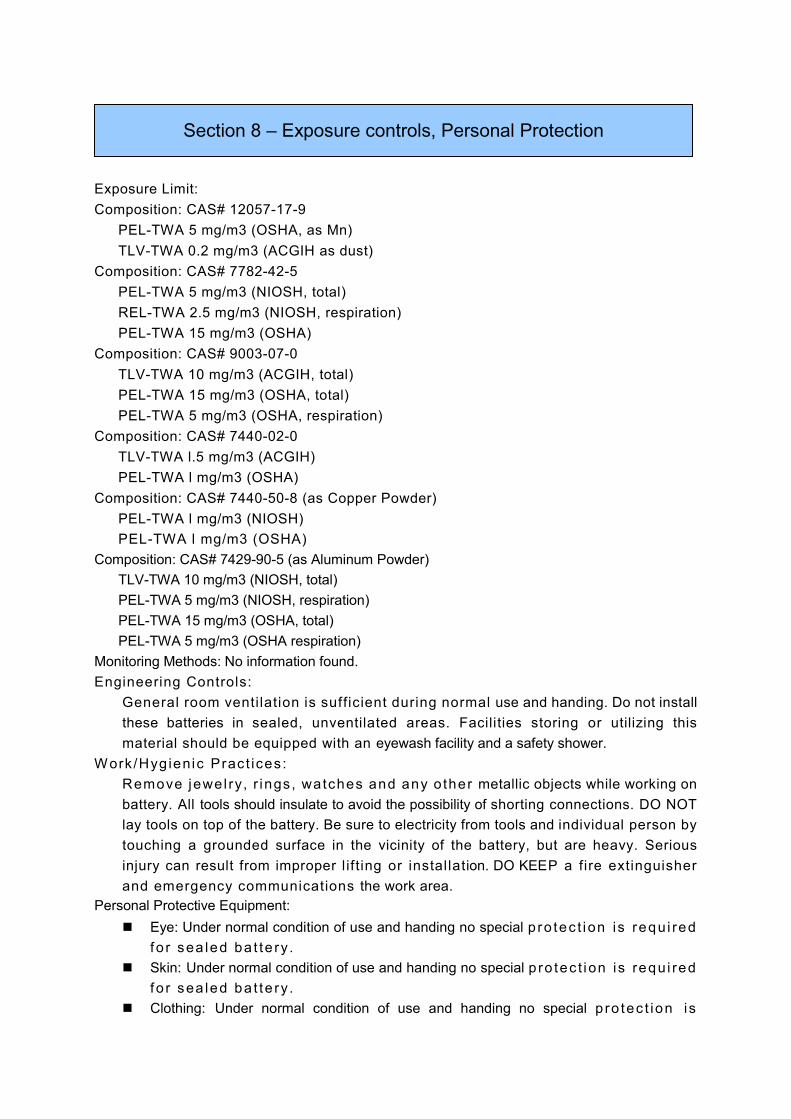
Exposure Limit:
Composition: CAS# 12057-17-9
PEL-TWA 5 mg/m3 (OSHA, as Mn)
TLV-TWA 0.2 mg/m3 (ACGIH as dust)
Composition: CAS# 7782-42-5
PEL-TWA 5 mg/m3 (NIOSH, total)
REL-TWA 2.5 mg/m3 (NIOSH, respiration)
PEL-TWA 15 mg/m3 (OSHA)
Composition: CAS# 9003-07-0
TLV-TWA 10 mg/m3 (ACGIH, total)
PEL-TWA 15 mg/m3 (OSHA, total)
PEL-TWA 5 mg/m3 (OSHA, respiration)
Composition: CAS# 7440-02-0
TLV-TWA l.5 mg/m3 (ACGIH)
PEL-TWA l mg/m3 (OSHA)
Composition: CAS# 7440-50-8 (as Copper Powder)
PEL-TWA l mg/m3 (NIOSH)
PEL-TWA l mg/m3 (OSHA)
Composition: CAS# 7429-90-5 (as Aluminum Powder)
TLV-TWA 10 mg/m3 (NIOSH, total)
PEL-TWA 5 mg/m3 (NIOSH, respiration)
PEL-TWA 15 mg/m3 (OSHA, total)
PEL-TWA 5 mg/m3 (OSHA respiration)
Monitoring Methods: No information found.
Engineering Controls:
General room venti lation is sufficient during normal use and handing. Do not install
these batteries in sealed, unventilated areas. Facilities storing or utilizing this
material should be equipped with an eyewash facility and a safety shower.
Work /Hyg ienic Pract ices:
Remove jewel ry, r ings, watches and any o ther metallic objects while working on
battery. All tools should insulate to avoid the possibility of shorting connections. DO NOT
lay tools on top of the battery. Be sure to electricity from tools and individual person by
touching a grounded surface in the vicinity of the battery, but are heavy. Serious
injury can result from improper l if t ing or instal lation. DO KEEP a fire extinguisher
and emergency communications the work area.
Personal Protective Equipment:
� Eye: Under normal condition of use and handing no special p ro tec t i on is requ i red
fo r sea led ba t te ry .
� Skin: Under normal condition of use and handing no special p ro tec t i on is requ i red
fo r sea led ba t te ry .
� Clothing: Under normal condition of use and handing no special p ro tec t ion is
Section 8 – Exposure controls, Personal Protection
requ i red fo r sea led ba t te ry .
� Respirators: Under normal condition of use and handing no special p ro tect ion is
requi red for sealed bat tery.
Personal Pro tect ive Equipment ( ln the Event o f Bat tery Case Breakage) :
Always wear appropriate safety glasses with side shields or full face shield. Use
appropriate gloves. Wear appropriate boots, apron or clothing. Use appropriate
respirator.
Other P ro tec t ion :
No smok ing o r ea t ing scene work . To ma in ta in good health habits. Wash
hands thoroughly after working with battery and before eating, drinking or smoking.
Physical State: White solid
Odor: Odorless
Voltage: 2.75-48 V
Capacitance: 100-40000 mAh
Weight: 10-4000 g
Chemical Uses: Electrical source
Chemical Stability: Stable under normal use.
Conditions to Avoid:
When a battery cell is exposed to an external short-circuit, crushed, modification, high
temperature above 100 'C, low temperature -10 'C, it will be the cause of heat generation.
and ignition. Direct sunlight and high humidity.
Incompatibilities with Other Materials:
Conductive materials, water, seawater, strong oxidizers and acids. Hazardous
Decomposition Products: Harmful gas is emitted during fire.
Hazardous Polymerization: Will not occur.
Toxicological Information:
Composition: CAS# 12057-17-9
- RTECS# Unlisted
- LD50: 9000 mg/kg (Oral, Guinea pig, as Mn )
Composition: CAS# 7782-42-5
- RTECS# MD9659600
Section 9 – Physical and Chemical Properties
Section 10 – Stability and reactivity
Section 11 – Toxicological Information
- LD50r LC50: Unlisted
Composition: CAS# 9003-07-0
- RTECS# UD1842000
- LD50:>110 mg/kg (lntraperitoneal, rat)
- LD50:>99 mg/kg (Intravenous, rat)
Composition: CAS# 24937-79-9
RTECS# Unlisted
- LD50, LC50: Unlisted
Composition: CAS# 9002-88-4
- RTECS# KX3270000 TQ3325000
- LD50: >2000 mg/kg (Oral, rat)
- LC50: 12 g/m3/30M (Inhalation, mouse)
Composition: CAS# 9004-32-4
- RTECS# FJ5950000
- LC50:≥5800 mg/m3/4h (Inhalation, rat)
- LD50: 27000 mg/kg (Oral, rat)
- LD50:≥27 g/kg (Oral, mouse)
- LD50:≥27 g/kg (Oral, rabbit)
- LD50:≥2 g/kg (Skin, rabbit)
Composition: CAS# 21324-40-3
- RTECS# Unlisted
- LD50: >1702 mg/kg (Oral, rat)
Composition: CAS# 96-49-1
- RTECS# FF9550000
- LD50: >10000 mg/kg (Oral, rat)
- LD50: >3000 mg/kg (Skin, rabbit)
Composition: CAS# 616-38-6
- RTECS# FG0450000
- LD50: >6000 mg/kg (Oral, mouse)
- LD50: >13000 mg/kg (Oral, rat)
- LD50:;5 g/kg (Skin, rabbit)
Composition: CAS# 7440-02-0
- RTECS# QR5950000 QR6126100 QR6555000 QR7120000
- LD50: >2 g/kg (Skin, rabbit)
Composition: CAS# 7440-50-8
- RTECS# GL5325000 GL440000 GL7590000
- LD50: >1124 mg/kg (Oral, rat)
- LD50: >2058 mg/kg (Oral, rabbit)
- LC50: 1303 mg/m3 (Inhalation, rabbit)
Composition: CAS# 7429-90-5
- RTECS# BD0330000 BD1020000
- LD50, LC50: Unlisted
Carcinogenicity:
Composition: CAS# 9003-07-0
- IARC: Group 3-Not classifiable as to carcinogenicity to humans.
- Not listed by ACGIH, NTP, or CA Prop 65.
Composition: CAS# 9002-88-4
- IARC: Group 3-Not classifiable as to carcinogenicity to humans.
- Not listed by ACGIH, NTP, or CA Prop 65.
Composition: CAS# 7440-02-0
- ACGIH: A5-Not suspected as a human carcinogen.
- California: carcinogen; initial date 10/1/89.
- OSHA: Possible Select carcinogen
- IARC: Group 28 carcinogen-Possibly carcinogenic to humans
- NTP: Listed as Nickel Compounds and Metallic Nickel
Other compositions of this product are not listed by ACGIH, IARC, NTP, or
CA Prop 65.
Sensitization Rate: Not available.
Teratogenicity: Not available.
Ecological Toxicity: Not available.
Ecological Degradation: Not available.
Biology Degradation: Not available.
Other Information: If the battery is discarded into the environment, the
harmful contents inside may be dangerous.
Chemical waste generators must determine whether a discarded chemical is classified as a
hazardous waste. Additionally, waste generators must consult state and local hazardous
waste regulations to ensure complete and accurate classification.
RCRA P-Series: None listed.
RCRA U-Series: None listed.
Regulated as a hazardous material for transportation. (IATA DGR)
UN: 3480
Classification:
Packaging Sign:
Section 12 – Ecological Information
Section 13 – Disposal Considerations
Section 14 – transport Information
Shipping Name: LITHIUM BATTERIES
Transport: Fashion: Cargo by air
Packaging Category: 11
Packaging Method: N/A
Other Information: Packing instruction 968
Regulated as a hazardous material for transportation. (IMDG CODE)
UN: 3480
Classification: 9
Packaging Sign:
Shipping Name: LITHIUM BATTERIES
Transport Fashion: Cargo by sea
Packaging Category: lI
Packaging Method: N/A
Other Information: Special provisions 188, 230, 310, and 957.
Regulatory Information:
Reference to the local, national, US and EU / international regulations.
TSCA: All of the chemicals in this product are listed.
DSL or NDSL: All of the chemicals in this product are listed
Except CAS#12057-17-9.
OSHA: CAS# 7440-02-0 is listed.
CAS# 7440-50-8 is listed.
CAS# 7429-90-5 is listed.
California Prop 65: CAS# 7440-02-0 is listed.
Chemical Name
CAS No.
Hazard
Symbols
Risk
Description
Safety
Description
Lithium Manganese
Oxide
12057-17-9
Xi
R 36/37
S22
Graphite
7782-42-5
Xi
R 36/37
s
22-26-37/39.
Polypropylene 9003-07-0 N/A N/A S 24/25
Poly(vinylidene
fluoride)
24937-79-9
N/A
N/A
S 22-24/25
Polythene
9002-88-4
N/A
N/A
S 24/25-
28A-37-45
Section 15 – Regulatory Information
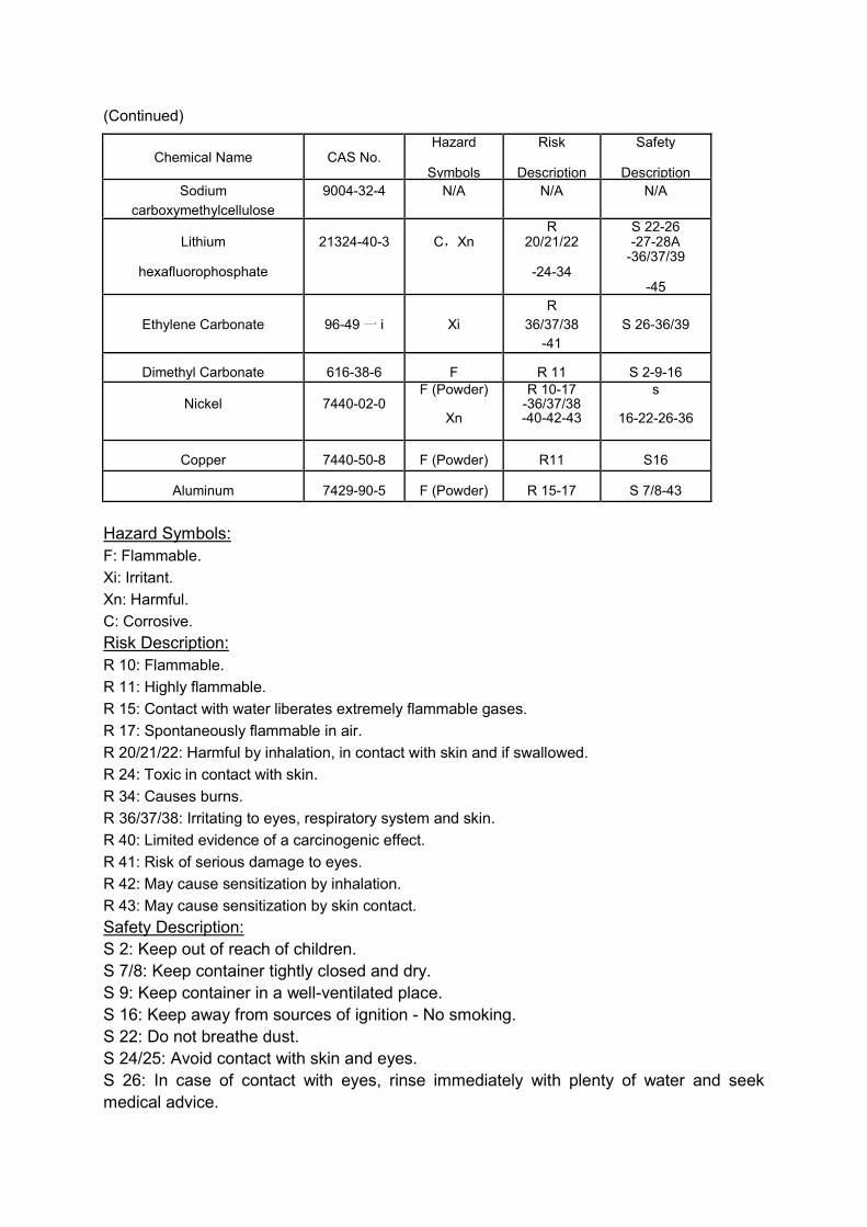
(Continued)
Hazard Symbols:
F: Flammable.
Xi: Irritant.
Xn: Harmful.
C: Corrosive.
Risk Description:
R 10: Flammable.
R 11: Highly flammable.
R 15: Contact with water liberates extremely flammable gases.
R 17: Spontaneously flammable in air.
R 20/21/22: Harmful by inhalation, in contact with skin and if swallowed.
R 24: Toxic in contact with skin.
R 34: Causes burns.
R 36/37/38: Irritating to eyes, respiratory system and skin.
R 40: Limited evidence of a carcinogenic effect.
R 41: Risk of serious damage to eyes.
R 42: May cause sensitization by inhalation.
R 43: May cause sensitization by skin contact.
Safety Description:
S 2: Keep out of reach of children.
S 7/8: Keep container tightly closed and dry.
S 9: Keep container in a well-ventilated place.
S 16: Keep away from sources of ignition - No smoking.
S 22: Do not breathe dust.
S 24/25: Avoid contact with skin and eyes.
S 26: In case of contact with eyes, rinse immediately with plenty of water and seek
medical advice.
Chemical Name
CAS No.
Hazard
Symbols
Risk
Description
Safety
Description
Sodium
carboxymethylcellulose
9004-32-4
N/A
N/A
N/A
Lithium
hexafluorophosphate
21324-40-3
C,Xn
R 20/21/22
-24-34
S 22-26 -27-28A
-36/37/39
-45
Ethylene Carbonate
96-49一 i
Xi
R
36/37/38
-41
S 26-36/39
Dimethyl Carbonate 616-38-6 F R 11 S 2-9-16
Nickel
7440-02-0
F (Powder)
Xn
R 10-17 -36/37/38 -40-42-43
s
16-22-26-36
Copper 7440-50-8 F (Powder) R11 S16
Aluminum 7429-90-5 F (Powder) R 15-17 S 7/8-43
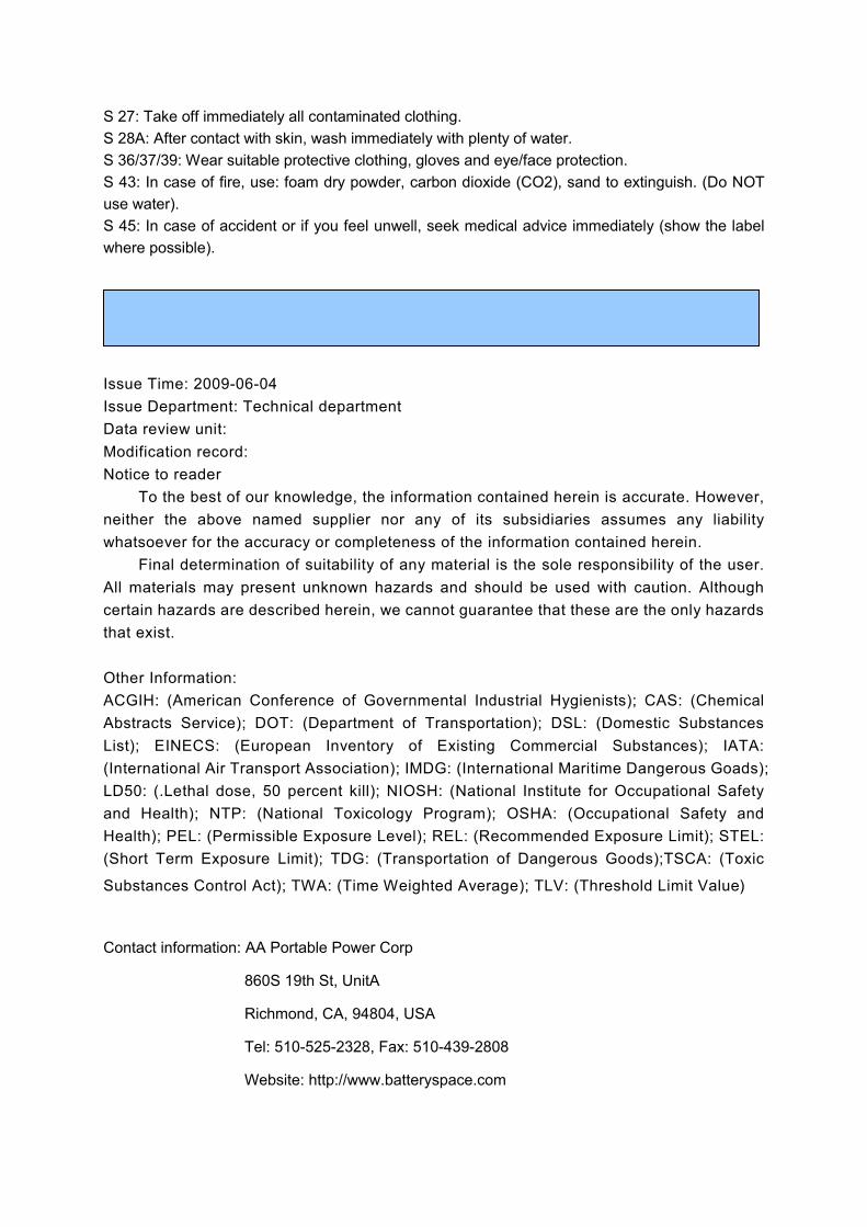
S 27: Take off immediately all contaminated clothing.
S 28A: After contact with skin, wash immediately with plenty of water.
S 36/37/39: Wear suitable protective clothing, gloves and eye/face protection.
S 43: In case of fire, use: foam dry powder, carbon dioxide (CO2), sand to extinguish. (Do NOT
use water).
S 45: In case of accident or if you feel unwell, seek medical advice immediately (show the label
where possible).
Issue Time: 2009-06-04
Issue Department: Technical department
Data review unit:
Modification record:
Notice to reader
To the best of our knowledge, the information contained herein is accurate. However,
neither the above named supplier nor any of its subsidiaries assumes any liability
whatsoever for the accuracy or completeness of the information contained herein.
Final determination of suitability of any material is the sole responsibility of the user.
All materials may present unknown hazards and should be used with caution. Although
certain hazards are described herein, we cannot guarantee that these are the only hazards
that exist.
Other Information:
ACGIH: (American Conference of Governmental Industrial Hygienists); CAS: (Chemical
Abstracts Service); DOT: (Department of Transportation); DSL: (Domestic Substances
List); EINECS: (European Inventory of Existing Commercial Substances); IATA:
(International Air Transport Association); IMDG: (International Maritime Dangerous Goads);
LD50: (.Lethal dose, 50 percent kill); NIOSH: (National Institute for Occupational Safety
and Health); NTP: (National Toxicology Program); OSHA: (Occupational Safety and
Health); PEL: (Permissible Exposure Level); REL: (Recommended Exposure Limit); STEL:
(Short Term Exposure Limit); TDG: (Transportation of Dangerous Goods);TSCA: (Toxic
Substances Control Act); TWA: (Time Weighted Average); TLV: (Threshold Limit Value)
Contact information: AA Portable Power Corp
860S 19th St, UnitA
Richmond, CA, 94804, USA
Tel: 510-525-2328, Fax: 510-439-2808
Website: http://www.batteryspace.com
Section 16 – Additional Information
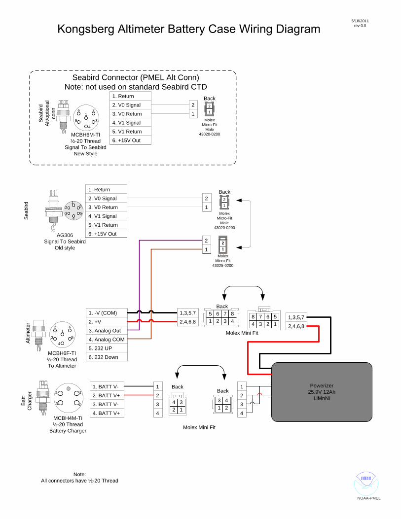
5/18/2011rev 0.0
NOAA-PMEL
43
21
6
5
1. Return
2. V0 Signal
3. V0 Return
4. V1 Signal
5. V1 Return
6. +15V Out
1. -V (COM)
2. +V
3. Analog Out
4. Analog COM
5. 232 UP
6. 232 Down
43
21
6
5
2
14
3
1. BATT V-
2. BATT V+
3. BATT V-
4. BATT V+
123
45
6
1. Return
2. V0 Signal
3. V0 Return
4. V1 Signal
5. V1 Return
6. +15V Out
MCBH6M-TI½-20 Thread
Signal To SeabirdNew Style
AG306Signal To Seabird
Old style
MCBH6F-TI½-20 ThreadTo Altimeter
MCBH4M-Ti½-20 Thread
Battery Charger
2
1
2
1Molex
Micro-Fit43025-0200
21
Back
1 23 4
1234
Back1
2
3
4
1 2 35 6 7
48
Back1,3,5,7
2,4,6,8
Back
MolexMicro-Fit
Male43020-0200
21
1
2
3
4
1,3,5,7
2,4,6,8246
378
15
2
1
Back
MolexMicro-Fit
Male43020-0200
21
Note:All connectors have ½-20 Thread
Powerizer25.9V 12Ah
LiMnNi
Molex Mini Fit
Molex Mini Fit
Alti
met
erB
att
Cha
rger
Sea
bird
Alt/
optio
nal
conn
Sea
bird
Seabird Connector (PMEL Alt Conn)Note: not used on standard Seabird CTD
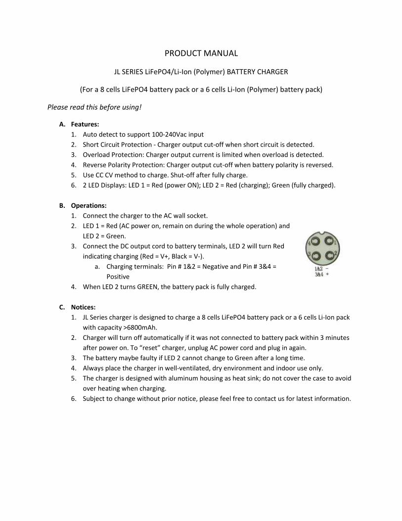
PRODUCT MANUAL
JL SERIES LiFePO4/Li-Ion (Polymer) BATTERY CHARGER
(For a 8 cells LiFePO4 battery pack or a 6 cells Li-Ion (Polymer) battery pack)
Please read this before using!
A. Features:
1. Auto detect to support 100-240Vac input
2. Short Circuit Protection - Charger output cut-off when short circuit is detected.
3. Overload Protection: Charger output current is limited when overload is detected.
4. Reverse Polarity Protection: Charger output cut-off when battery polarity is reversed.
5. Use CC CV method to charge. Shut-off after fully charge.
6. 2 LED Displays: LED 1 = Red (power ON); LED 2 = Red (charging); Green (fully charged).
B. Operations:
1. Connect the charger to the AC wall socket.
2. LED 1 = Red (AC power on, remain on during the whole operation) and
LED 2 = Green.
3. Connect the DC output cord to battery terminals, LED 2 will turn Red
indicating charging (Red = V+, Black = V-).
a. Charging terminals: Pin # 1&2 = Negative and Pin # 3&4 =
Positive
4. When LED 2 turns GREEN, the battery pack is fully charged.
C. Notices:
1. JL Series charger is designed to charge a 8 cells LiFePO4 battery pack or a 6 cells Li-Ion pack
with capacity >6800mAh.
2. Charger will turn off automatically if it was not connected to battery pack within 3 minutes
after power on. To “reset” charger, unplug AC power cord and plug in again.
3. The battery maybe faulty if LED 2 cannot change to Green after a long time.
4. Always place the charger in well-ventilated, dry environment and indoor use only.
5. The charger is designed with aluminum housing as heat sink; do not cover the case to avoid
over heating when charging.
6. Subject to change without prior notice, please feel free to contact us for latest information.
®®
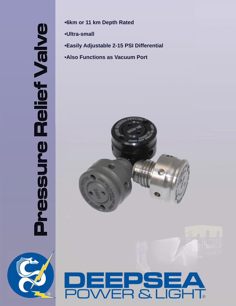
•6km or 11 km Depth Rated
•Ultra-small
•Easily Adjustable 2-15 PSI Differential
•Also Functions as Vacuum Port
DEEPSEA®POWER & LIGHT
®®
DEEPSEAPower & Light®
4033 Ruffi n RoadSan Diego, CA 92123ph: (858) 576-1261
[email protected]: (858)576-0219
Specifi cations subject to change without notice.
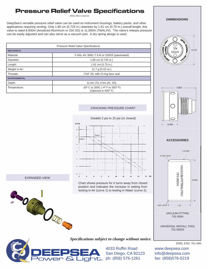
Pressure Relief Valve SpecificationsSPEC REV A 3/31/10
DeepSea’s versatile pressure relief valve can be used on instrument housings, battery packs, and other applications requiring venting. Only 1.85 cm (0.725 in.) diameter by 1.91 cm (0.75 in.) overall length, this valve is rated 6,000m (Anodized Aluminum or 316 SS) or 11,000m (Ti6AL4V). The valve’s release pressure can be easily adjusted and can also serve as a vacuum port. A dry spring design is used.
DSPL ENG 701-000
MECHANICAL
Material: Ti 6AL-4V, 6061-T 6 Al or 316SS (passivated)
Diameter: 1.85 cm (0.725 in.)
Length: 1.91 cm (0.75 in.)
Weight in Air: 11.7 g (0.42 oz.)
Threads: 7/16”-20, with O-ring face sealENVIRONMENTAL
Depth: 11 km (Ti); 6 km (AI, SS)
Temperature: -20º C to 200C (-4º F to 392º F) (Optional to 500º F)
Pressure Relief Valve Specifi cations
CRACKING PRESSURE CHART
Setable 2 psi to 15 psi (or closed)
Chart shows pressure for # turns away from closed position and indicates the increase in setting from testing in Air (curve 1) to testing in Water (curve 2).
EXPANDED VIEW
ACCESSORIES
DIMMENSIONS
VACUUM FITTING701-0004
UNIVERSAL INSTALL TOOL 701-00020
0.725
0.850
0.400
VACUUM FITTING
0.100 x 45.0º
0.05 x 45.0º
1/4” NPT
(2.000)
1.10

Setup Instructions: PMEL Real-Time Altimeter for Seabird 9/11 CTD
18
APPENDIX C
ALTCONFIG
Operator manual
Configuration Software for the Model 1007 Altimeter

All rights reserved. No parts of this work may be reproduced in any form or by any means - graphic, electronic, ormechanical, including photocopying, recording, taping, or information storage and retrieval systems - without thewritten permission of the publisher.
Products that are referred to in this document may be either trademarks and/or registered trademarks of therespective owners. The publisher and the author make no claim to these trademarks.
While every precaution has been taken in the preparation of this document, the publisher and the author assume noresponsibility for errors or omissions, or for damages resulting from the use of information contained in this documentor from the use of programs and source code that may accompany it. In no event shall the publisher and the author beliable for any loss of profit or any other commercial damage caused or alleged to have been caused directly orindirectly by this document.
ALTCONFIG
Copyright 2004...Kongsberg Mesotech Ltd
Technical Editor
...Gary Mochizuki...
Kongsberg Mesotech Ltd.
1598 Kebet Way, Port Coquitlam, BC, V3C 5M5 CanadaTelephone +1 604 464 8144 Telefax +1 604 941 5423
www.kongsberg-mesotech.comEmail [email protected]

Kongsberg Mesotech Ltd. warrants that its products are free from defective materialsand/or workmanship for a period of 12 months from the date of receipt of goods bythe end user, or 18 months from the date of product shipment from themanufacturing facility (which ever occurs first). Kongsberg Mesotech Ltd. will - at nocharge - repair or replace (at its option) any part(s) determined to be defective ofworkmanship or materials, provided the warranty claim is made to either themanufacturing facility, or its authorized repair centers within the warrany period.
The purchaser is responsible for the examination of the product upon receipt. Thepurchaser is required to report any irregularity to received Kongsberg Mesotech Ltd.goods to either the manufacturer - its Sister companies - or Agents, within 15 days ofreceipt of goods. Proof of date received may be required.
The warranty is void if warranty labels are broken; Kongsberg Mesotech Ltd. will notwarrant any product which is physically damaged, abused, altered, subjected toaccident or negligence or misuse, or is incorrectly installed or used by the purchaser -or purchaser's representative.
Consumable items (includeing lamps, fuses, and worn O rings or shaft-seals) areexcluded by the warranty.
All Product/Equipment returned under warranty shall have freight charges "prepaid". All Product/Equipment forwarded under warranty will be freight charges "prepaid" byKongsberg Mesotech Ltd.
NOTE: Shipping method and carrier for warranty return will be at the discretion ofKongsberg Mesotech Ltd.
Kongsberg Mesotech cannot warranty that its products are suitable for any particularor intended purpose. No other warranty is expressed or implied; KongsbergMesotech Ltd. accepts no liability of consequential damages. Consequentialdamages include, but are not limited to: loss of profit, property damage, personalinjury.
The maximum liability shall not, in any case, exceed the price of the product claimedto be defective.
Kongsberg Mesotech Ltd.Warranty Statement

Table of Contents
Foreword 0
Part I Contents 3
Part II Introduction 5
................................................................................................................................... 51 General Description
................................................................................................................................... 52 Model 1007 Altimeter
................................................................................................................................... 63 Theory of Operation
Part III Installation 8
................................................................................................................................... 81 System Requirements
................................................................................................................................... 82 Installation
Part IV Usage 10
................................................................................................................................... 101 Configuration Sequence
................................................................................................................................... 102 Altimeter Configuration
................................................................................................................................... 123 Configuration Files
................................................................................................................................... 134 Troubleshooting
Part V Reference 16
................................................................................................................................... 161 File Menu
................................................................................................................................... 162 View Menu
................................................................................................................................... 163 Initialize Menu
................................................................................................................................... 164 Configure Menu
................................................................................................................................... 175 Help Menu
Part VI Appendix 19
................................................................................................................................... 191 Appendix
................................................................................................................................... 192 MS1000 software
................................................................................................................................... 193 Model MS1000 Power Supply/Interface Box
................................................................................................................................... 204 Contacting Us
................................................................................................................................... 205 Glossary
Index 22
ALTCONFIGI
Copyright © 2004 Kongsberg Mesotech

Contents
ALTCONFIG Operator's Manual
Part
I

ALTCONFIG3
Copyright © 2004 Kongsberg Mesotech
1 Contents
General Description
Model 1007 Altimeter
Theory of Operation
System Requirements
Installation
Configuration Files
Configuration Sequence
Altimeter Configuration Dialog Box
Troubleshooting
File Menu
View Menu
Initialize Menu
Configure Menu
Help Menu
Appendix

Introduction
ALTCONFIG Operator's Manual
Part
II
ALTCONFIG5
Copyright © 2004 Kongsberg Mesotech
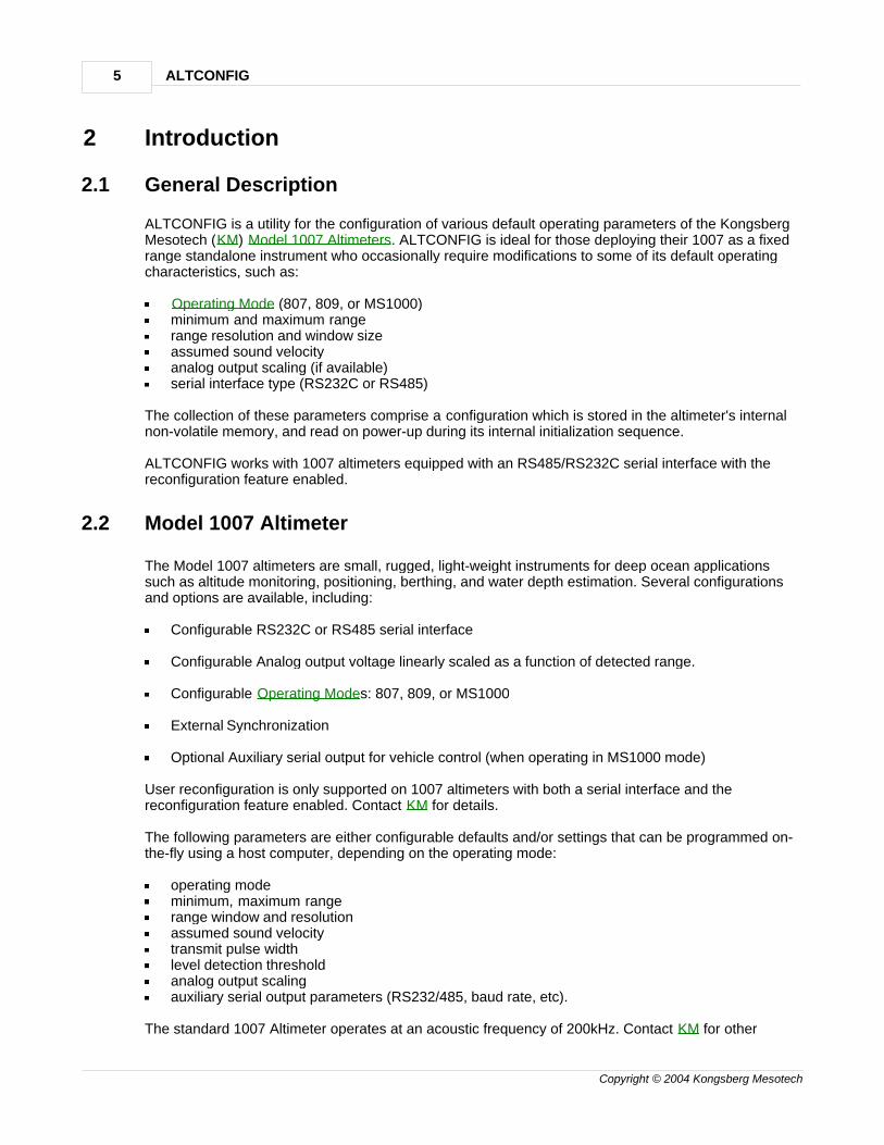
2 Introduction
2.1 General Description
ALTCONFIG is a utility for the configuration of various default operating parameters of the KongsbergMesotech (KM) Model 1007 Altimeters. ALTCONFIG is ideal for those deploying their 1007 as a fixedrange standalone instrument who occasionally require modifications to some of its default operatingcharacteristics, such as:
Operating Mode (807, 809, or MS1000)minimum and maximum rangerange resolution and window sizeassumed sound velocityanalog output scaling (if available)serial interface type (RS232C or RS485)
The collection of these parameters comprise a configuration which is stored in the altimeter's internalnon-volatile memory, and read on power-up during its internal initialization sequence.
ALTCONFIG works with 1007 altimeters equipped with an RS485/RS232C serial interface with thereconfiguration feature enabled.
2.2 Model 1007 Altimeter
The Model 1007 altimeters are small, rugged, light-weight instruments for deep ocean applicationssuch as altitude monitoring, positioning, berthing, and water depth estimation. Several configurationsand options are available, including:
Configurable RS232C or RS485 serial interface
Configurable Analog output voltage linearly scaled as a function of detected range.
Configurable Operating Modes: 807, 809, or MS1000
External Synchronization
Optional Auxiliary serial output for vehicle control (when operating in MS1000 mode)
User reconfiguration is only supported on 1007 altimeters with both a serial interface and thereconfiguration feature enabled. Contact KM for details.
The following parameters are either configurable defaults and/or settings that can be programmed on-the-fly using a host computer, depending on the operating mode:
operating modeminimum, maximum rangerange window and resolutionassumed sound velocitytransmit pulse widthlevel detection thresholdanalog output scalingauxiliary serial output parameters (RS232/485, baud rate, etc).
The standard 1007 Altimeter operates at an acoustic frequency of 200kHz. Contact KM for other
Introduction 6
Copyright © 2004 Kongsberg Mesotech
frequencies. Refer to the 1007 Altimeter Specifications Sheet and Operators Manual for moreinformation.
Operating Modes
807 mode
All parameters in the altimeter are fixed (e.g. range, resolution, window, etc.) during operation,therefore cannot be changed on-the-fly via serial commands. This mode is typically used with 1007altimeters with the analog output option in applications that only require the altimeter to output altitudemeasurements in analog (voltage) form as a standalone instrument.
809 mode
A standalone mode backward-compatible with the KM Model 809 Programmable Digital Echo Sounderoutputting data via serial interface (RS232 or RS485) to a host computer or data logger. Normally usedin applications with a PC host used as a terminal emulator or running a custom, application-specificsoftware. On-the-fly programmable parameters (e.g. range, resolution, window, etc.) via serialcommands from a host computer.
MS1000 mode
For connection via serial interface (RS232 or RS485) to a host computer running the KMMS1000 software application. This is a slave-oriented mode i.e. every ping is initiated by the hostcomputer. Provides the ultimate in control and flexibility.
2.3 Theory of Operation
ALTCONFIG works by overriding the current/default operating mode of the target 1007 Altimeter byissuing commands via serial interface using KM's proprietary protocol.
Configuration data is then read directly non-volatile memory inside the altimeter and displayed in an"Altimeter Configuration" dialog box in a summarized form. Some of the configuration settings can thenbe user-modified in the dialog box, or the entire configuration can be replaced entirely by any one ofthe configuration files included with this utility.
The new and/or modified settings can then be downloaded to update the altimeter's internal non-volatile memory. The altimeter is then automatically reset (via command) and the configuration data isreread and logged to a text file for diagnostic purposes.
The reconfigured altimeter is then ready to use, requiring only that altimeter be powered off prior to firstuse.

Installation
ALTCONFIG Operator's Manual
Part
III
Installation 8
Copyright © 2004 Kongsberg Mesotech
3 Installation
3.1 System Requirements
ALTCONFIG requires a PC with an available COM port and running either Windows 9x, Me, NT, or2000. Preferably, the same PC will be used to with the 1007 altimeter if using a digital serial interface.
1007 altimeters can only be reconfigured if they have a digital serial interface (RS232 or RS485) andhave the user reconfiguration feature enabled. Therefore, analog-output altimeters cannot bereconfigured. Contact KM regarding user reconfigurabiliby.
3.2 Installation
No special installation procedure of ALTCONFIG is required. Simply copy all the files in theALTCONFIG software package to a dedicated directory (e.g. "c:\altconfig") in the host PC. A shortcutto "altconfig.exe" should then be created on the desktop for convenience.
ALTCONFIG supports only single head operation per COM port. Disconnect all other devicesconnected to the same COM port as the altimeter of interest.

Usage
ALTCONFIG Operator's Manual
Part
IV
Usage 10
Copyright © 2004 Kongsberg Mesotech
4 Usage
4.1 Configuration Sequence
1007 Altimeter reconfiguration is a two-part procedure. Before commencing, make sure there are noother PC applications currently running that require access to serial ports (e.g. MS1000, HyperTerminal,WinFax, etc).
Initialization
1. Start ALTCONFIG.
2. Select "Initialize...Port" and specify the serial (COM) port used to connect the PC to the targetedaltimeter. This needs to be done only once each time ALTCONFIG is started, or if another serialport needs to selected.
3. With the altimeter turned OFF, select "Initialize...Altimeter". An mode-overriding serial transmissionsequence will be continuously issued to the altimeter while a "Altimeter Initialization" pop-up boxwill be displayed. Do not click on the "OK" button yet.
4. Turn ON the altimeter, then wait approximately 5 seconds after power is applied.
5. Click on the "OK" button in the "Altimeter Initialization" pop-up box to terminate transmission. Thealtimeter should now be ready for configuration operations.
Configuration
1. Select "Configure...1007 Altimeter" to establish communications with the altimeter and read thecurrent configuration parameters from the altimeter's non-volatile memory. The main display areadisplays the messaging sequence involved. If successful, an "Altimeter Configuration" dialog boxwill be displayed, summarizing the configuration information read from the altimeter. Theconfiguration read is also saved in the text report file "altimeter.rep" for diagnostic reference.
2. Edit the parameters as required for 809 or MS1000 mode, OR select/load a new configuration fileby clicking on the "Load from File" button.
3. Click on "Write to Head" button to write the configuration information to the altimeter's non-volatilememory, reset the altimeter, and read back the configuration information. The main display logsthe messaging sequence involved, which can be saved later in a ".ACL" text file. Configurationinformation is logged to a text report file "altimeterw.rep" for diagnostic purposes.
4. The configuration information is then read back to update both the "Altimeter Configuration" dialogbox and the text report file "altimeter.rep" for diagnostic comparison with "altimeterw.rep".
5. Turn OFF altimeter power. The altimeter is now ready to use with the new configuration.
4.2 Altimeter Configuration
The "Altimeter Configuration" pop-up dialog box summarizes the configuration parameters read fromthe altimeter, along with controls and adjustments to allow the user to modify them. This dialog box
ALTCONFIG11
Copyright © 2004 Kongsberg Mesotech
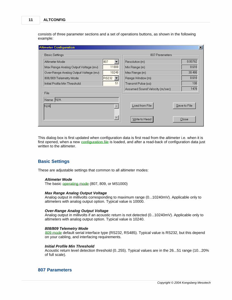
consists of three parameter sections and a set of operations buttons, as shown in the followingexample:
This dialog box is first updated when configuration data is first read from the altimeter i.e. when it isfirst opened, when a new configuration file is loaded, and after a read-back of configuration data justwritten to the altimeter.
Basic Settings
These are adjustable settings that common to all altimeter modes:
Altimeter ModeThe basic operating mode (807, 809, or MS1000)
Max Range Analog Output VoltageAnalog output in millivolts corresponding to maximum range (0...10240mV). Applicable only toaltimeters with analog output option. Typical value is 10000.
Over-Range Analog Output VoltageAnalog output in millivolts if an acoustic return is not detected (0...10240mV). Applicable only toaltimeters with analog output option. Typical value is 10240.
808/809 Telemetry Mode809 mode default serial interface type (RS232, RS485). Typical value is RS232, but this dependon your cabling, and interfacing requirements.
Initial Profile Min ThresholdAcoustic return level detection threshold (0..255). Typical values are in the 26...51 range (10...20%of full scale).
807 Parameters
Usage 12
Copyright © 2004 Kongsberg Mesotech
These are parameters specific to 807 mode only, summarized from a number of settings not displayedor accessible in this dialog box and cannot be modified.
ResolutionRange resolution in millimeters.
Min RangeMinimum measured range in meters. This is set to start after the end of the transmit pulse pluspost-pulse transducer ringing.
Max RangeMaximum measured range in meters.
Range WindowMaximum allowed difference between range readings. Used to filter out large range changes dueto noise or interference.
Transmit PulseTransmit pulse length in microseconds.
Assumed Velocity of SoundVelocity of sound used to estimate range in meters per second.
File
Displays the configuration file name and specifications banner stored in it and cannot be modified. Notapplicable to configuration data read from the altimeter.
Buttons
Load from FileReads and displays configuration information from a user-selected configuration file.
Save to FileSaves the currently displayed configuration information to a user-selected configuration file.
Write to HeadWrites the displayed configuration information to the altimeter's non-volatile memory andgenerates a text report file "altimeterw.rep". ALTCONFIG then resets the altimeter and reads backthe configuration information, updates the displayed parameters, and updates the file"altimeter.rep" for diagnostic comparison with "altimeterw.rep". The main display area logs themessaging sequence involved, which can be saved later in a ".ACL" text file.
CloseCloses the "Altimeter Configuration" dialog box.
4.3 Configuration Files
ALTCONFIG includes several ".CFG" text files which represent several configurations covering most ofthe typical 1007 applications. These configurations can be split into two major classes: fixed-rangeoperation and programmable operation. The ".CFG" files are by default stored in the same directory asALTCONFIG, along with "README.TXT", which summarizes their attributes.
ALTCONFIG13
Copyright © 2004 Kongsberg Mesotech
Configuration files are used in a manner similar to Windows ".INI" files with many interdependentparameters and therefore must *NOT* be modified in any way! Consult KM for any specificconfiguration requirements.
4.4 Troubleshooting
1007 Altimeter reconfiguration should be relatively error free if it has been correctly installed and theConfiguration Sequence is correctly followed. For correct operation, ensure that the followingprerequisites are met:
ALTCONFIG is correctly installed in a PC meeting all System Requirements.
ALTCONFIG supports only 1007 Altimeters with serial interfaces. Analog-only 1007 Altimeters andother devices such as 1071 digital heads are not supported.
ALTCONFIG only supports re-configuration of 1007 Altimeters that have reconfiguration featuresenabled. Altimeters without this feature cannot be reconfigured. Contact KM for details.
ALTCONFIG supports only single head operation per COM port. Disconnect all other devicesconnected to the same COM port as the altimeter to be configured.
Verify that the unit provides a digital serial interface and that the mating cable is correctly wired forthe altimeter. Altimeters with an analog-only output are not supported by ALTCONFIG.
If an error message is logged on the main display area, for example:
"Head timeout: CommID=...""Altimeter configuration mismatch..."
or if the "Altimeter Configuration" dialog box fails to display, then try the following suggestions beforeretrying Configuration Sequence:
Close all other PC applications requiring serial (COM) port access, such as HyperTerminal, WinFax,MS1000, etc.
Check all connections/cabling between the host PC, altimeter, and your power source. Verify theCOM port selected in ALTCONFIG corresponds to the COM port used for connection to thealtimeter.
Verify power is being supplied to the altimeter within the specified voltage range and currenthandling capacity. Refer to the Model 1007 Altimeter Specifications Sheet for details.
Confirm the PC's COM port operation by either connecting to a known working serial portperipheral (such as a mouse) or by a serial loopback test. Alternatively, try another COM port ifavailable.
If using an Model MS1000 Power Supply/Interface Box, verify the front panel POWER indicator islit when power is turned ON. Confirm the front panel Tx and Rx indicators momentarily flash after"Configure...1007 Altimeter" is selected, indicating serial communications with the altimeter.
In the case of a configuration mismatch error, compare the log files "altimeterw.rep" (configurationinformation written to altimeter) and "altimeter.rep" (configuration information read back) to see ifthere are any differences. Patterns in the mismatch may aid in the diagnosis.

Usage 14
Copyright © 2004 Kongsberg Mesotech
Contact KM if further assistance is required.

Reference
ALTCONFIG Operator's Manual
Part
V
Reference 16
Copyright © 2004 Kongsberg Mesotech
5 Reference
5.1 File Menu
Clear LogClears the main display area, which lists the messages issued to the altimeter.
Save LogSaves the current contents of the main display area to the current text log file for diagnostic purposes.By default, the current log file is initially "untitled.acl".
Save Log AsSaves the current contents of the main display to a text log file other than the current log file.
ExitTerminates the ALTCONFIG application.
5.2 View Menu
Status BarEnables or disables the status bar immediately below the main display area.
5.3 Initialize Menu
PortSelects the serial (COM) port connected to the altimeter. This needs to be selected only once afterALTCONFIG is started, or if another serial port is to be used.
AltimeterOpens the "Altimeter Initialization" dialog box and enables the continuous transmission of aninitialization sequence to the altimeter for overriding the altimeter's operating mode on power-up. Clickon the "OK" button approximately 5 seconds after altimeter power-up to terminate the transmission.
The overriding sequence has no effect on altimeters already powered-up and running in a standalonemode (807 or 809).
5.4 Configure Menu
1007 AltimeterReads configuration data from the targeted altimeter. If successful, opens up the"Altimeter Configuration" dialog box for display and modification of configuration data.

ALTCONFIG17
Copyright © 2004 Kongsberg Mesotech
5.5 Help Menu
ContentsDisplays a list of help topics.
AboutDisplays the ALTCONFIG version.

Appendix
ALTCONFIG Operator's Manual
Part
VI
ALTCONFIG19
Copyright © 2004 Kongsberg Mesotech
6 Appendix
6.1 Appendix
MS1000 software
Model MS1000 Power Supply/Interface Box
Contacting Us
Glossary
6.2 MS1000 software
KM's Windows-based sonar application. that provides the ultimate in control and flexibility of Model1007 Altimeters.
Some of the features:
compatible with a number of KM sonar heads and altimeterssupports single or multiple head/altimeter operation.sonar data recording/playback.echo sounder imaging.screen capture and printoutpowerful target measurement toolsflexible display configurationaccepts external navigation and sensor information for display and/or data logging.serial output of optional sensor data.for Windows 95/98/ME or NT/2000.
Contact KM for further details and specifications.
6.3 Model MS1000 Power Supply/Interface Box
KM's integrated power supply / interface unit for use in systems using the MS1000 host software.
+24V power for KM digital telemetry heads and altimeters,
RS485/232 interface conversion between the head/altimeter and PC for multi-drop configurations(single cable/multiple heads).
Contact KM for further details and specifications.
Appendix 20
Copyright © 2004 Kongsberg Mesotech
6.4 Contacting Us
Kongsberg Mesotech Ltd.1598 Kebet WayPort Coquitlam, B.C.CanadaV3C 5M5
tel: (604) 464-8144fax: (604) 941-5423e-mail: [email protected]: http://www.kongsberg-mesotech.com
Kongsberg Mesotech (KM) is a wholly owned subsidiary of the Kongsberg Group of companies(Norway). MS1000, Model 1007 Altimeter, and ALTCONFIG are copyright 2001 Kongsberg Mesotech,All rights reserved.
6.5 Glossary
configuration
A collection of parameters that specify the operating behavior and measurement properties of thealtimeter.
fixed range operation
An operating mode where all parameters (e.g. range, resolution, window, etc.) are fixed duringoperation, therefore cannot be changed on-the-fly via serial commands. This mode is typically usedwith 1007 altimeters with the analog output option in applications only require the altimeter to outputaltitude measurements in analog (voltage) form. The 807 operating mode is an example of a fixed-range operating mode.
Operating Mode
The 1007 Altimeter can operate in several operating modes (807, 808, 809, MS1000) that are furtherdescribed in the "1007 Altimeter Operator's Manual".
ping
ALTCONFIG21
Copyright © 2004 Kongsberg Mesotech
A single altitude measurement cycle, consisting of the following sequence:a. transmission of an insonifying acoustic tone burst,b. receive signal data acquisition interval (duration determined by maximum range),c. receive data analysis and altitude estimation.
programmable operation
An operating mode with parameters (e.g. range, resolution, window, etc.) programmable on-the-fly viaserial commands from a host computer. This mode is typically used in applications where the altimeteris connected to a host computer for control and data uplink via a serial interface (RS232 or RS485).The 809 and MS1000 operating modes are examples of modes with programmable operation.
standalone operation
Autonomous pinging and output of altitude measurements in digital and/or analog form i.e. does notrequire host computer control to initiate pinging. The 807 and 809 operating modes are examples ofmodes catered for standalone operation.
Index- C -Configuration Files 12Configuration Sequence 10Configure Menu 16
1007 Altimeter 16Contacting Us 20Contents 3
- F -File Menu 16
Clear Log 16Exit 16Save Log 16Save Log As 16
- G -General Description 5
- H -Help 17Help Menu 17
About 17Index 17
- I -Initialize Menu 16
Altimeter 16Port 16
Installation 8
- M -Model 1007 Altimeter 5MS1000 Power Supply 19
- O -operating mode 5, 20Operating Modes 5
- S -System Requirements 8
- T -Theory of Operation 6Troubleshooting 13
- V -View Menu 16
Status Bar 16
Index 22
Copyright © 2004 Kongsberg Mesotech