Embed Size (px)
Citation preview
INSTITUT ZA RUDARSTVO I METALURGIJU BOR KOMITET ZA PODZEMNU EKSPLOATACIJU MINERALNIH SIROVINA
RUDARSKI RADOVI je časopis baziran na bogatoj tradiciji stručnog i naučnog rada u oblasti rudarstva, podzemne i površinske eksploatacije, pripreme mineralnih sirovina, geologije, mineralogije, petrologije, geomehanike i povezanih srodnih oblasti. Izlazi dva puta godišnje od 2001. godine, a od 2011. godine četiri puta godišnje.
Glavni i odgovorni urednik Akademik dr Milenko Ljubojev, naučni savetnik Institut za rudarstvo i metalurgiju Bor E-mail: [email protected] Tel. 030/454-109, 435-164
Zamenik glavnog i odgovornog urednika Dr Mirko Ivković, viši naučni saradnik Komitet za podzemnu eksploataciju mineralnih sirovina Resavica E-mail: [email protected] Tel. 035/627-566
Urednik Vesna Marjanović, dipl.inž.
Prevodilac Nevenka Vukašinović, prof.
Tehnički urednik Suzana Cvetković, teh.
Priprema za štampu Ljiljana Mesarec, teh.
Štamparija: Grafomedtrade Bor
Tiraž: 200 primeraka
Internet adresa www.irmbor.co.rs
Izdavanje časopisa finansijski podržavaju Ministarstvo za prosvetu i nauku Republike Srbije Institut za rudarstvo i metalurgiju Bor Komitet za podzemnu eksploataciju mineralnih sirovina Resavica
ISSN 1451-0162 Indeksiranje časopisa u SCIndeksu i u ISI. Sva prava zadržana.
Izdavač Institut za rudarstvo i metalurgiju Bor 19210 Bor, Zeleni bulevar 35 E-mail: [email protected] Tel. 030/454-110 Komitet za podzemnu eksploataciju mineralnih sirovina Resavica E-mail: [email protected] Tel. 035/627-566 Naučno - tehnička saradnja sa Inženjerskom Akademijom Srbije
Uređivački odbor Prof. dr Živorad Milićević
Tehnički fakultet Bor Akademik Prof. dr Mladen Stjepanović
Inženjerska akademija Srbije Prof. dr Vladimir Bodarenko
Nacionalni rudarski univerzitet, Odeljenje za podzemno rudarstvo, Ukrajina
Prof. dr Miroslav Ignjatović Institut za rudarstvo i metalurgiju Bor
Prof. dr Milivoj Vulić Univerzitet u Ljubljani, Slovenija
Akademik Prof. dr Jerzy Kicki Državni institut za mineralne sirovine i energiju, Krakov, Poljska
Prof. dr Vencislav Ivanov Rudarski fakultet Univerziteta za rudarstvo i geologiju "St. Ivan Rilski" Sofija Bugarska
Prof. dr Tajduš Antoni Stanislavov univerzitet za rudarstvo i metalurgiju, Krakov, Poljska
Dr Dragan Komljenović Nuklearna generatorska stanica G2, Hidro-Quebec, Kanada
Prof. dr Dušan Gagić Rudarsko geološki fakultet Beograd
Prof. dr Nebojša Vidanović Rudarsko geološki fakultet Beograd
Prof. dr Neđo Đurić Tehnički institut, Bijeljina, Republika Srpska, BiH
Prof. dr Vitomir Milić Tehnički fakultet Bor
Prof. dr Rodoljub Stanojlović Tehnički fakultet Bor
Prof. dr Mevludin Avdić RGGF-Univerzitet u Tuzli, BiH
Prof. dr Nenad Vušović Tehnički fakultet Bor
Dr Miroslav R. Ignjatović, viši naučni saradnik Privredna komora Srbije
Dr Mile Bugarin, viši naučni saradnik Institut za rudarstvo i metalurgiju Bor
Dr Dragan Zlatanović Ministarstvo životne sredine, rudarstva i prostornog planiranja Srbije
Dr Miodrag Denić JP za podzemnu eksploataciju Resavica
Dr Ružica Lekovski, naučni saradnik Institut za rudarstvo i metalurgiju Bor
Dr Jovo Miljanović Rudarski fakultet Prijedor RS, BiH
Dr Zlatko Dragosavljević Ministarstvo životne sredine, rudarstva i prostornog planiranja Srbije
Prof. dr Kemal Gutić RGGF-Univerzitet u Tuzli, BiH
VODEĆI ČASOPIS NACIONALNOG ZNAČAJA M51 ZA 2012.
MINING AND METALLURGY INSTITUTE BOR COMMITTEE OF UNDERGROUND EXPLOITATION OF THE MINERAL DEPOSITS
MINING ENGINEERING is a journal based on the rich tradition of expert and scientific work from the field of mining, underground and open-pit mining, mineral processing, geology, mineralogy, petrology, geomechanics, as well as related fields of science. Since 2001, published twice a year, and since 2011 four times year. Editor-in-chief
Academic Ph.D. Milenko Ljubojev, Principal Reasearch Fellow, Associate member of ESC Mining and Metallurgy Institute Bor E-mail: [email protected] Phone: +38130/454-109, 435-164
Co-Editor Ph.D. Mirko Ivković, Senior Research Associate Committee of Underground Exploitation of the Mineral Deposits Resavica E-mail: [email protected] Phone: +38135/627-566
Editor Vesna Marjanović, B.Eng.
English Translation Nevenka Vukašinović
Technical Editor Suzana Cvetković
Preprinting Ljiljana Mesarec
Printed in: Grafomedtrade Bor Circulation: 200 copies Web site
www.irmbor.co.rs MINING ENGINEERING is financially supported by
The Ministry of Education and Science of the Republic Serbia Mining and Metallurgy Institute Bor Committee of Underground Exploitation of the Mineral Deposits Resavica
ISSN 1451-0162 Journal indexing in SCIndex and ISI. All rights reserved. Published by
Mining and Metallurgy Institute Bor 19210 Bor, Zeleni bulevar 35 E-mail: [email protected] Phone: +38130/454-110 Committee of Underground Exploitation of the Mineral Deposits Resavica E-mail: [email protected] Phone: +38135/627-566 Scientific – Teshnical Cooperation with the Engineering Academy of Serbia
Editorial Board Prof.Ph.D. Živorad Milićević
Technical Faculty Bor Academic Prof.Ph.D. Mladen Stjepanović
Engineering Academy of Serbia Prof.Ph.D. Vladimir Bodarenko
National Mining University, Department of Deposit Mining, Ukraine
Prof.Ph.D. Miroslav Ignjatović Mining and Metallurgy Institute Bor
Prof.Ph.D. Milivoj Vulić University of Ljubljana, Slovenia
Academic Prof.Ph.D. Jerzy Kicki Gospodarkl Surowcami Mineralnymi i Energia, Krakow, Poland
Prof.Ph.D. Vencislav Ivanov Mining Faculty, University of Mining and Geology "St. Ivan Rilski" Sofia Bulgaria Prof.Ph.D. Tajduš Antoni
The Stanislaw University of Mining and Metallurgy, Krakow, Poland
Ph. D. Dragan Komljenović Nuclear Generating Station G2, Hydro-Quebec, Canada
Prof.Ph.D. Dušan Gagić Faculty of Mining and Geology Belgrade
Prof.Ph.D. Nebojša Vidanović Faculty of Mining and Geology Belgrade
Prof.Ph.D. Neđo Đurić Technical Institute, Bijeljina, Republic Srpska, B&H
Prof.Ph.D. Vitomir Milić Technical Faculty Bor Prof.Ph.D. Rodoljub Stanojlović,
Technical Faculty Bor Prof.Ph.D. Mevludin Avdić
MGCF-University of Tuzla, B&H Prof.Ph.D. Nenad Vušović
Technical Faculty Bor Ph.D. Miroslav R. Ignjatović, Senior Research Associate
Chamber of Commerce and Industry Serbia Ph.D. Mile Bugarin, Senior Research Associate
Mining and Metallurgy Institute Bor Ph.D. Dragan Zlatanović
Ministry of Environment, Physical Planing and Mining of Republic Serbia
Ph.D. Miodrag Denić PC for Underground Exploitation Resavica
Ph.D. Ružica Lekovski, Research Associate Mining and Metallurgy Institute Bor
Ph.D. Jovo Miljanović Faculty of Mining in Prijedor, RS, B&H
Ph.D. Zlatko Dragosavljević Ministry of Environment, Physical Planing and Mining of Republic Serbia
Prof.Ph.D. Kemal Gutić MGCF-University of Tuzla, B&H
LEADING NATIONAL JOURNAL CATEGORIZATION M51 FOR 2012.
SADR@AJ CONTENS
Ratomir Popović, Milenko Ljubojev, Dragan Ignjatović, Lidija Đurđevac - Ignjatović MEHANIZAM DEFORMISANJA STENSKOG MASIVA OKO TUNELA KRUŽNOG POPREČNOG PRESEKA NA TRASI „KRIVELJSKA REKA“ IZGRAĐENOG U JEDNORODNOJ IZOTROPNOJ STENSKOJ MASI ..........................................................................................1
MECHANISM OF DEFORMATION THE ROCK MASS AROUND THE TUNNEL OF CIRCULAR SECTION ON THE “KRIVELJ RIVER” ROUTE BUILT IN THE HOMOGENOUS ISOTROPIC ROCK MASS......................................................................................................7
Miodrag Miljković, Rodoljub Stanojlović, Jovica Sokolović SIGURNOSNE I DEFORMACIONE KARAKTERISTIKE ZASIPNIH MATERIJALA U RUDNICIMA .....................................................................................................13
SAFETY AND DEFORMATION CHARACTERISTICS OF STOPING MATERIALS IN THE MINES .........................................................................................................21
Ratomir Popović, Milenko Ljubojev, Dragan Ignjatović, Lidija Đurđevac Ignjatović VIBRACIJE TEMELJA NA ELASTO-PLASTIČNOJ OSNOVI PRI KONSTANTNO DELUJUĆOJ I PERIODIČNOJ SILI......................................................................................29
VIBRATIONS OF FOUNDATION ON ELASTIC-PLASTIC BASE AT CONSTANT AND PERIODICAL ACTING FORCE........................................................................................33
Mirko Ivković, Mile Bugarin, Sead Softić TEHNOLOGIJA UGRADNJE PRSKANOG BETONA KOD PODGRAĐIVANJA PODZEMNIH RUDARSKIH PROSTORIJA .....................................................................................................37
TECHNOLOGY OF SPRAYED CONCRETE LINING IN SUPPORT OF UNDERGROUND MINING FACILITIES.........................................................................................................43
Boško Vuković, Vesna Ljubojev TEHNOLOŠKI POSTUPCI POVEĆANJA STEPENA ISKORIŠĆENJA TOPLOTNE VRIJEDNOSTI UGLJA KAO ENERGETSKOG RESURSA LEŽIŠTA GACKO...........................................49
TECHNOLOGICAL PROCESSES OF INCREASING THE EFFICIENCY OF CALORIFIC VALUE OF COAL AS THE ENERGY RESOURCE OF THE GACKO DEPOSIT .................57
Dragomir Bukumirović, Mensud Turković, Zdravko Zarić STRUKTURNO ISPITIVANJE SLOJEVA U JAMI RMU „ŠTAVALJ“ .........................................................65
STRUCTURAL INVESTIGATION OF SEAMS IN THE PIT OF THE BROWN COAL MINE “ŠTAVALJ”..................................................................................................................73
Mirko Ivković, Mile Bugarin, Sead Softić NOVA METODOLOGIJA OCENE UGROŽENOSTI EKSPLOZIVNOM UGLJENOM PRAŠINOM U JAMAMA RMU „REMBAS“ – RESAVICA ...........................................................................81
THE NEW RISK ASSESSMENT METHODOLOGY FOR EXPLOSION OF COAL DUST IN RMU "REMBAS" - RESAVICA............................................................................................87
Srđana Magdalinović, Vesna Marjanović, Daniela Urošević, Dragiša Stanujkić FLOTACIJSKA KONCENTRACIJA POLIMETALIČNE BARITSKE RUDE ...............................................93
FLOTATION CONCENTRATION OF POLYMETALLIC BARITE ORE......................................................99
Mensud Turković, Dragomir Bukumirović, Gojko Radeka, Safet Mušović POTENCIJALNOST I PERSPEKTIVNOST PODZEMNE EKSPLOATACIJE UGLJA U SJENIČKOM UGLJENOM BASENU..............................................................................................................105
POTENTIALITY AND PROSPECTS OF UNDERGROUND COAL MINING IN THE SJENICA COAL BASIN ...................................................................................................................................115
Bojan Drobnjaković, Dragan Milanović, Vesna Drobnjaković, Branislav Čađenović REKONSTRUKCIJA ČLANKASTOG DODAVAČA DROBILIČNOG POSTROJENJA ZA RUDU/JALOVINU NA POVRŠINSKOM KOPU RUDNIKA VELIKI KRIVELJ........................................125
RECONSTRUCTION THE APRON FEEDER OF THE CRUSHING PLANT FOR ORE/WASTE AT THE OPEN PIT OF THE VELIKI KRIVELJ MINE .........................................................131
Branislav Čađenović, Vesna Marjanović, Vesna Ljubojev, Dragan Milanović MOGUĆNOST ISKORIŠĆENJA BAKRENCA IZ TOPIONIČKE ŠLJAKE KOD NJENOG DIREKTNOG IZLIVANJA IZ PEĆI................................................................................................137
POSSIBILITIES OF USE THE COPPER MATTE FROM SMELTER SLAG IN ITS DIRECT BAKRENCA OF SMELTING SLAG IN ITS DIRECT DISCHARGE FROM FURNACE ..........143
Ljiljana Savić, Vladimir Radovanović, Ljubinko Savić, Radiša Janković FAKTORI EKONOMSKE USPEŠNOSTI U RUDNICIMA ...........................................................................149
FACTORS OF ECONOMIC SUCCESS IN THE MINES ...............................................................................157
Broj 2,2012. RUDARSKI RADOVI
1
INSTITUT ZA RUDARSTVO I METALURGIJU BOR YU ISSN: 1451-0162 KOMITET ZA PODZEMNU EKSPLOATACIJU MINERALNIH SIROVINA UDK: 622
UDK: 551.49:622.26:622.01(045)=861
Ratomir Popović*, Milenko Ljubojev*, Dragan Ignjatović*, Lidija Đurđevac - Ignjatović*
MEHANIZAM DEFORMISANJA STENSKOG MASIVA OKO TUNELA KRUŽNOG POPREČNOG PRESEKA NA TRASI „KRIVELJSKA REKA“ IZGRAĐENOG U JEDNORODNOJ
IZOTROPNOJ STENSKOJ MASI**
Izvod
U radu su prikazani naponi u plastičnoj zoni prostorije kružnog poprečnog preseka izgrađenoj u jednorodnoj izotropnoj stenskoj masi. Takođe je određena veličina zone RT u kojoj se formiraju mikropukotine oko podzemne prostorije. Ta zona je određena u zavisnosti od veličine otpora podgrade i primenjenog reološkog modela analizirane stenske mase.
Ključne reči: jednorodna izotropna stensa masa, naponsko-deformacijsko stanje stenske mase
* Institut za rudarstvo i metalurgiju Bor ** Ovaj rad je proistekao iz Projekta broj 33021 „Istraživanje i praćenje promena naponsko
deformacionog stanja u stenskom masivu“ in-situ“ oko podzemnih prostorija sa izradom modela sa posebnim osvrtom na tunel Kriveljske reke i Jame Bor“, koga finansira Ministarstvo za prosvetu i nauku Republike Srbije
UVOD
Pri rešavanju problema stabilnosti podzemnih prostorija polazi se od dva osnovna stava:
- načina na koji dolazi do izmene pri-rodnog naponskog stanja stenskog ma-siva uzrokovanog izradom podzemne prostorije
- kako reaguju dotične stene na te izmene.
Predmet geomehanike je da ukaže na uzajamne veze ukoliko su osnovne defor-macije stenske mase izazvane preraspo-delom naponskog stanja, što u određenom broju dovodi do njihovog progresivnijeg deformisanja.
Teoretske postavke se baziraju u
sadašnje vreme na primeni stenskog modela oko podzemne prostorije sa nekoliko raspoređenih zona sa različitim mehaničko-deformabilnim karakteristikama. Pri ovome, osnovni problem pri izvođenju analitičkog rešenja za određivanje stabilnosti i veličine deformacija konture podzemne prostorije je u iznalaženju metode prognoziranja, koja uzima u obzir najoptimalnije karakteristike dubokih horizonata za proces rušenja stena oko podzemne prostorije. To je vezano s tim što klasična rešenja zasnovana na elasto-plastičnom zadatku daju deformacije kon-ture prostorije bliske faktičnim (izmerenim)
Broj 2,2012. RUDARSKI RADOVI
2
samo pri mehaničkim parametrima znatno manjim od onih dobijenih ispitivanjem na uzorcima. Za eliminisanje te protivrečnosti uključuje se koeficijent oslabljenja stenske mase. Razlike, koje se najupečatljivije uočavaju u neslaganju rezultata, vezane su za različiti prilaz dozvoljenoj čvrstoći stena konture poprečnog preseka podzemne prostorije u zoni neelastičnih deformacija. Uvođenje dozvoljene čvrstoće, vezano je za raši-renost uslova čvrstoće Kulon-Mora ostvarujući pri prelazu stena u granično stanje na slučaj zagraničnih deformacija. Aproksimacija funkcije sniženja čvrstoće karakterističnim različitim analitičkim funkcijama ne daje zadovoljavajući rezu-ltat, a da istovremeno zadovolji opis datog eksperimenta. Prihvatljiviji je složeniji pristup rešenja datog zadatka, uzimajući u obzir zonu uticajnog rušenja i ispucalost stena oko prostorije, neophodno je u svakom konkretnom slučaju povećati broj uzoraka stena za ispitivanje, što se pra-ktično ne realizuje u stadijumu prognoze.
Naznačene protivrečnosti uslovljene su isključivo složenošću istraživanog objekta. Oblast oko prostorije u principu je isprese-cana sistemom pukotina. Na taj način, zona neelastičnih deformacija predstavljena stena-ma, izdeljena je pukotinama i blokovima. Pri sastavljanju jednačina kontinuma za takvu sredinu, obično sastavljamo jednačine za fenomenologičnu sredinu sa parametrima zapremine ΔV, ili formiramo te jednačine sa početnom razmerom, koja malo reprezen-tatuje razmeru mikrostrukture, a uprosečuje je po zapremini.
- U prvom slučaju, uprosečenost (osred-njavanje) se sprovodi u odsustvu mogućnosti stvarnog utvrđivanja specijalnih reoloških opita za for-miranje sistema jednačina koje formu-lišu zakonitost stenske mase u celini.
- U drugom slučaju, oblik formiranih jednačina, a ponekad i konkretne vrednosti reoloških parametara, odre-đeni su teoretski.
Razmatrajući proces defomisanja zone neelastičnih deformacija, koja je obrazovana oko podzemne prostorije; u procesu obrazovanja te zone, stenska masa je izdeljena sistemom pukotina na blokove. Pri tom, bez obzira na to što zona stenske mase oko prostorije dobija nepovratne (neelastične) deformacije, a svaki od blokova podčinjava se zakonu elastičnih deformacija. To se potvrđuje faktom da uzorak stene izvađen iz zone neelastičnih deformacija pri ispitivanju ponaša se kao elastično telo. Uočena osobenost daje mogućnost predstaviti zonu neelastičnih deformacija kao sredinu koja je u stanju elastičnog stanja sa mikrostrukturom. Mikrostruktura je određena (definisana) početnom mikroispucalošću stena. Ako izdelimo celokupnu stensku masu na zapreminu i izjednačimo po razmeri sa mikroispucalošću, tada možemo uzeti u obzir ranije rečeno, da ta izdvojena zapremina se ponaša po zakonu teorije elastičnosti.
1. NAPONSKO-DEFORMACIJSKO STANJE STENSKE MASE OKO PODZEMNE PROSTORIJE
1.1. Naponsko stanje stenske mase oko podzemne prostorije
Izvedena podzemna rudarska prosto-rija na znatnoj dubini gde je H više puta veće od poluprečnika prostorije Ro. To je osnovna pretpostavka da su stene na konturi podzemne prostorije u plastičnom stanju. Polazeći od navedene pretpostavke i usvajajući uslov čvrstoća Kulon-Mora i kriterijum rušenja Grifits-a, polazni sistem jednačina je sledeći:
Broj 2,2012. RUDARSKI RADOVI
3
( )ϕσσσσ θθ Kctgrr ++=− sin (1)
( ) ( ) 08 312
31 =++− σσσσσ z (2)
σz – otpornost stene sa mikropukotinama na zatezanje
Naglašavamo da dati model omogu-ćava sprovesti razmišljanja (rasuđivanja) bez ograničenja za bilo koji uslov plastičnosti i kriterijum rušenja.
1.1.1. Zona neelastičnih deformacija
Saglasno određenim rešenjima, naponi u plastičnoj zoni imaju oblik:
( )( )( )
⎪⎭
⎪⎬
⎫
=⋅−⋅+⋅+=
⋅−⋅⋅+=
01
2
θ
αθ
τϕαϕσ
ϕϕσ
r
r
ctgKrctgKPctgKrctgKP
(3)
gde je:
ϕϕα
sin1sin2−
=
P – otpor lučne podgrade Razmatrajući sada malu elastičnu zapre-
minu u plastičnoj zoni sa mikropukotinama i uvrštavanjem izraza (3) u (2), dobija se uslov rasta mikropukotina u slučaju izrade kružne podzemne prostorije.
( )( )( )[ ] 02
82
222
=⋅−⋅+⋅+⋅
⋅+⋅⋅⋅+
ϕαϕσαϕ α
ctgKrctgKPrctgKP z (4)
Rešenjem izraza (4) po rα dobije se:
( ) ( )( )
2222 224 α
ϕϕασασασα
ctgKPctgKr zzz
+⋅⋅++±+
⋅=
(5)
Sada se mora pronaći veza između K i σz. Stena sa mikropukotinama može se u celini razmatrati kao ravnijsko telo sa graničnom čvrstoćom na zatezanje
ησασ ⋅=Mz
- ησ , pretstavlja teoretsku čvrstoću
- α , koeficijent elipsastog defekta Koristeći uslov čvrstoće Kulon-Mora,
lako je dobiti vezu zMz σσ ⋅= 2
( )ϕ
ϕσcos
sin1+−= zK (6)
Uvrštavajući (6) u (5) i vršeći zamenu
ησPP =1 , dobije se
( )( )
( )ϕϕϕϕ
ϕϕα sinsinsinsinP
sinsinr −⋅++⋅
+−+= 1
11112 2
1 (7)
Izraz (7) daje dimenzije zone RT u kojoj počinju rast mikropukotine.
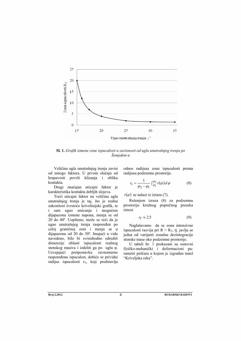
Moramo naglasiti da pri realnom otporu podgrade, radijus zone ispucalosti nastaje pri izradi prostorije i ne zavisi od mehaničkih karakteristika okolnih stena. Odlučujući faktor je samo ugao unutra-šnjeg trenja. Na sl. 1 grafički je prikazana izmena zone ispucalosti u zavisnosti od ugla unutražnjeg trenja.
Broj 2,2012. RUDARSKI RADOVI
4
Sl. 1. Grafik izmene zone ispucalosti u zavisnosti od ugla unutrašnjeg trenja po Šemjakin-u
Veličina ugla unutrašnjeg trenja zavisi
od mnogo faktora. U prvom slučaju od hrapavosti površi klizanja i oblika kontakta.
Drugi značajan uticajni faktor je karakteristika kontakta debljih slojeva.
Treći uticajni faktor na veličinu ugla unutrašnjeg trenja je taj, što je realna zakonitost čvrstoće krivolinijski grafik, te i sam ugao smicanja i mogućem dijapazonu izmene napona, menja se od 20 do 40º. Uopšteno, može se reći da je ugao unutrašnjeg trenja raspoređen po celoj graničnoj zoni i menja se u dijapazonu od 20 do 30º. Imajući u vidu navedeno, bilo bi svrsishodno odrediti dimenzije oblasti ispucalosti realnog stenskog masiva i izdeliti ga po uglu φ. Usvajajući pretpostavku ravnomerno raspoređenu ispucalost, dobiće se prividni radijus ispucalosti rT, koji predstavlja
odnos radijusa zone ispucalosti prema radijusu podzemne prostorije.
( ) ϕϕϕϕ
ϕϕτ drr ∫
−= 2
112
1 (8)
( )ϕr se nalazi iz izraza (7). Rešenjem izraza (8) za podzemnu
prostoriju kružnog poprečnog preseka iznosi
52,rT ≈ (9)
Naglašavamo da se zona intenzivne ispucalosti razvija pri R > RT, tj. javlja se jedna od varijanti zonalne dezintegracije stenske mase oko podzemne prostorije.
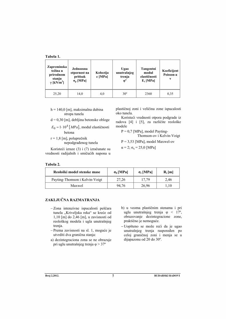
U tabeli br. 1 prokazani su osnovni fizičko-mehanički i deformacioni pa-rametri peščara u kojem je izgrađen tunel “Kriveljska reka”.
Broj 2,2012. RUDARSKI RADOVI
5
Tabela 1.
Zapreminska težina u
prirodnom stanju
γ [kN/m3]
Jednoosna otpornost na
pritisak σp [MPa]
Kohezija c [MPa]
Ugao unutrašnjeg
trenja φº
Tangentni modul
elastičnosti Et [MPa]
Koeficijent Poisson-a
ν
25,20 14,0 4,0 30º 2360 0,35
h = 140,0 [m], maksimalna dubina
stropa tunela d = 0,30 [m], debljina betonske obloge
[ ]MPaE 40 101⋅= , modul elastičnosti
betona r = 1,8 [m], poluprečnik
nepodgrađenog tunela
Koristeći izraze (3) i (7) izračunate su vrednosti radijalnih i smičućih napona u
plastičnoj zoni i veličina zone ispucalosti oko tunela.
Koristeći vrednosti otpora podgrade iz radova [4] i [5], za različite reološke modele
P = 0,7 [MPa], model Payting-Thomson-ov i Kelvin-Voigt
P = 3,53 [MPa], model Maxwel-ov α = 2; ση = 25,0 [MPa]
Tabela 2.
Reološki model stenske mase σθ [MPa] σr [MPa] Rt [m]
Payting-Thomson i Kelvin-Voigt 27,26 17,79 2,46 Maxwel 94,76 26,96 1,10
ZAKLJUČNA RAZMATRANJA
− Zona intenzivne ispucalosti peščara tunela „Kriveljska reka“ se kreće od 1,10 [m] do 2,46 [m], u zavisnosti od reološkog modela i ugla unutrašnjeg trenja.
− Prema zavisnosti na sl. 1, moguće je utvrditi dva granična stanja:
a) dezintegraciona zona se ne obrazuje pri uglu unutrašnjeg trenja φ > 37º
b) u veoma plastičnim stenama i pri
uglu unutrašnjeg trenja φ < 17º, obrazovanje dezintegracione zone, praktično je nemoguće.
− Uopšteno se može reći da je ugao unutrašnjeg trenja raspoređen po celoj graničnoj zoni i menja se u dijapazonu od 20 do 30º.
Broj 2,2012. RUDARSKI RADOVI
6
LITERATURA
[1] Šemjakim E. I., Fisenko G. L., Kurlejnja M. V. Zonalnaja dezintegracija gornih parod vokrug podzemnih virabotok, FTPRPI, 1986.
[2] Černjak I. L. Predatorasšćenije pučenija počvih gornih virabotok, M. Njedra, 1978.
[3] Fisenko G. L. Predelnije sastojanija gornih parod vokrug virabotok, Moskva, Njedra, 1976.
[4] Ljubojev M., Popović R., Bugarin M., Deformacioni pritisak, krutost pograde i karakteristike stenskog masiva trase tunela „Kriveljska reka“, Rudarski ra-dovi, 2(2008), Bor, str. 123 - 128.
[5] Popović R., Ljubojev M., Bugarin M., Osnove postavki mehaničkih modela sadejstva podgrade sa stenskim masi-vom, Bakar, 1(2007), str. 53 – 64.
[6] Ljubojev M., Popović R., Osnove geomehanike, RTB Bor, Institut za bakar, Bor, 2006.
[7] Popović R., Ljubojev M., Definisanje opterećenja na podgradu podzemne prostorije, Bakar, 1(2008), Bor, str. 1-16.
No 2, 2012. MINING ENGINEERING
7
MINING AND METALLURGY INSTITUTE BOR YU ISSN: 1451-0162 COMMITTEE OF UNDERGROUND EXPLOITATION OF THE MINERAL DEPOSITS UDK: 622
UDK: 551.49:622.26:622.01 (045)=20
Ratomir Popović*, Milenko Ljubojev*, Dragan Ignjatović*, Lidija Đurđevac - Ignjatović*
MECHANISM OF DEFORMATION THE ROCK MASS AROUND THE TUNNEL OF CIRCULAR SECTION ON THE “KRIVELJ RIVER”
ROUTE BUILT IN THE HOMOGENOUS ISOTROPIC ROCK MASS**
Abstract
This paper presents the stresses in the plastic zone circular cross-section room, built in the ho-mogenous isotropic rock mass. The size of the zone RT was also determined where the micro cracks are formed around the underground room. This zone is determined depending on the size of the support resistance and applied rheological model of the analyzed rock mass.
Keywords: homogeneous isotropic rock mass, stress-strain state of rock mass
* Mining and Metallurgy Institute Bor, 35 Zeleni bulevar, 19210 Bor ** This paper is produced from the project no. 33021 “Researching and monitoring changes in
stress-deformation condition of rock massif “in-situ” around undergraund facilities with devel-opment of model with special emphasis on Krivelj river tunnel and Bor pit”, which is funded by means of the Ministry of Education and Science of the Republic of Serbia
INTRODUCTION
To solve the problem of stability the underground rooms, it is started from two basic attitudes:
- the way in which there are changes in natural stress state of the rock mass caused by the construction the underground room,
- the reaction of respective rock mass to those changes.
The subject of geomechanics is to show the mutual connections if the basic rock mass deformations are caused by redistribution of stress state, which in the
certain number results to their progressive deformation.
Theoretical foundations are based nowadays on the use of rock model around the underground room with several distrib-uted zones with different mechanical-deformable characteristics. In this, the main problem in performing the analytical solu-tion for determining the stability and size of deformation the contour of underground room is in finding out a method of forecast-ing, which takes into account the most op-timum characteristics of deep horizons in the process of rocks destruction around the
No 2, 2012. MINING ENGINEERING
8
underground room. This is connected with the fact that the classical solutions, based on the elastoplastic task, give deforma-tions of the room contours close to the factual (measured) ones only in the me-chanical parameters significantly lower than those obtained by testing the samples.
To eliminate this contradiction, the coef-ficient of weakened rock mass is involved. The differences, which are the most striking, are observed in noncompliance of the re-sults, related to the different approach to the permitted strength of rock of cross section contour the underground room in the zone of inelastic deformations. Introduction of the permitted strength is related to the preva-lence of the Coulomb-More strength condi-tions strength in transition of rocks to the limit state in the case limit deformations. Approximation of functions for strength reduction by the characteristic variety of analytical functions do not give a satisfac-tory result, and to simultaneously meet the description of given experiment. More com-plex approach to the task solution is accept-able, taking into account the zone of influen-tial destruction and cracked rocks around the room; it is necessary in the certain case to increase the number of rock samples for testing, which is not practically implemented in a stage of forecast.
Designated contradictions are exclusively caused by complexity of investigated object. Thus, the inelastic deformation zone, repre-sented by the rocks, is divided by fissures and blocks. To compose the continuum equa-tions for such media, usually the equations are composed for fenomenological environ-ment with parameters of volume ΔV, or to form these equations with the initial ratio, which little represents the microstructure ratio and averages it by volume.
- In the first case, the averaging is performed in the absence of real possibility to establish the special rheological experiments for formation the system of equations that formulate the lawfulness of rock mass as a whole.
- In the second case, the shape of formed equations, and sometimes the actual values of rheological parameters were theoretically determined.
Considering the deformation process of inelastic deformation zone, which is formed around the underground room, in the formation process of this zone, the rock mass is divided by a system of cracks on the blocks. In addition, regardless of the fact that the zone of rock mass around the room gets irreversible (inelastic) de-formations, and each of the blocks is sub-mitted to the law of elastic deformations. This is confirmed by the fact that a rock sample, taken from the inelastic deforma-tion zone in the test behaves as an elastic body. The observed characteristic pro-vides the possibility to introduce the non-elastic deformation zone as an environ-ment that is in an elastic state with micro-structure. Microstructure is determined (defined) by the initial micro-cracked rocks. If the entire volume of the rock mass is divided and scale by ratio with micro-cracked rock, then the above can be taken into consideration and that this sepa-rated volume behaves according to the law of the elasticity theory.
1. STRESS-DEFORMATION STATE OF THE ROCK MASS AROUND THE UNDERGROUND ROOM
1.1. Stress state of the rock mass around the underground room
The constructed underground mining room is at a considerable depth, where H is several times higher than the room ra-dius Ro. This is the basic assumption that the rocks on the underground room con-tours are in a plastic state. Starting from these assumptions and by adopting the strength condition of the Coulomb-More and breaking criterion of the Grifits, the starting system of equations is as follows:
No 2, 2012. MINING ENGINEERING
9
( )ϕσσσσ θθ Kctgrr ++=− sin (1)
( ) ( ) 08 312
31 =++− σσσσσ z (2)
σz – tensile strength of rocks with micro cracks
It is emphasized that the given model enables implementation of reasoning without limitation for any of the plasticity condition and destruction criteria.
1.1.1. Zone of inelastic deformations
In accordance with the certain solu-tions, stresses in the plastic zone have the form:
( )( )( )
⎪⎭
⎪⎬
⎫
=⋅−⋅+⋅+=
⋅−⋅⋅+=
01
2
θ
αθ
τϕαϕσ
ϕϕσ
r
r
ctgKrctgKPctgKrctgKP
(3)
where:
ϕϕα
sin1sin2−
=
P – resistance of arched support Considering now a small elastic vol-
ume in the plastic zone of micro cracks and inclusion the expression (3) into (2), the condition of growth the micro cracks is obtained in the case of making a circu-lar underground chamber.
( )( )( )[ ] 02
82
222
=⋅−⋅+⋅+⋅
⋅+⋅⋅⋅+
ϕαϕσαϕ α
ctgKrctgKPrctgKP z (4)
By solution the expression (4) per rα, the following is obtained
( ) ( )( )
2222 22
4 αϕ
ϕασασασαctgKP
ctgKr zzz
+⋅⋅++±+
⋅=
(5)
Now, a relationship between K and σz has to be found out. Rocks with micro cracks can be considered as a whole body with limit tensile strength.
ησασ ⋅=Mz
- ησ , represents the theoretical strength - α , coefficient of elliptical defect Using the Coulomb-More strength
condition, it is easy to get a connection
zMz σσ ⋅= 2 .
( )ϕ
ϕσcos
sin1+−= zK (6)
Incorporating (6) into (5) and perform-
ing the replacement ησ
PP =1 , the fol-
lowing is obtained
( )( )
( )ϕϕϕϕ
ϕϕα sinsinsinsinP
sinsinr −⋅++⋅
+−+= 1
11112 2
1 (7)
Expression (7) gives the sizes of the zone RT where micro cracks begin to grow.
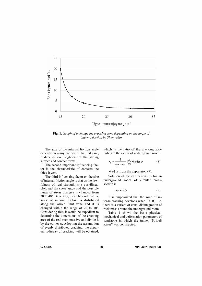
It should be emphasized that in the real resistance of roof supports, the radius of cracking zone occurs in the room con-struction and does not depend on the me-chanical characteristics of the surrounding rocks. Deciding factor is only the angle of internal friction. Figure 1 graphically shows a change of cracking zone changes depending on the angle of internal friction.
No 2, 2012. MINING ENGINEERING
10
Fig. 1. Graph of a change the cracking zone depending on the angle of internal friction by Shemyakin
The size of the internal friction angle
depends on many factors. In the first case, it depends on roughness of the sliding surface and contact forms.
The second important influencing fac-tor is the characteristic of contacts the thick layers.
The third influencing factor on the size of internal friction angle is that as the law-fulness of real strength is a curvilinear plot, and the shear angle and the possible range of stress changes is changed from 20 to 40º. Generally, it can be said that the angle of internal friction is distributed along the whole limit zone and it is changed within the range of 20 to 30º. Considering this, it would be expedient to determine the dimensions of the cracking area of the real rock massive and divide it by the corner φ. Adopting the assumption of evenly distributed cracking, the appar-ent radius rT of cracking will be obtained,
which is the ratio of the cracking zone radius to the radius of underground room.
( ) ϕϕϕϕ
ϕϕτ drr ∫
−= 2
112
1 (8)
( )ϕr is from the expression (7). Solution of the expression (8) for an
underground room of circular cross-section is
52,rT ≈ (9)
It is emphasized that the zone of in-tense cracking develops when R> RT, i.e. there is a variant of zonal disintegration of rock mass around the underground room.
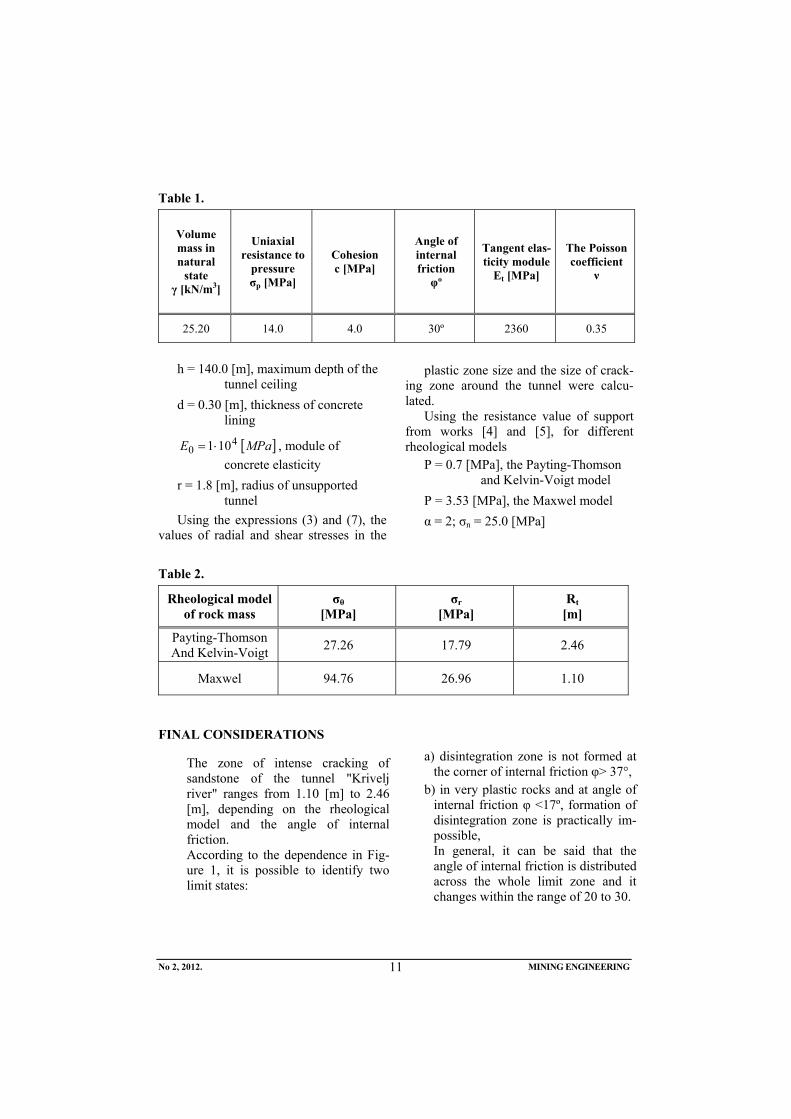
Table 1 shows the basic physical-mechanical and deformation parameters of sandstone in which the tunnel “Krivelj River” was constructed.
No 2, 2012. MINING ENGINEERING
11
Table 1.
Volume mass in natural
state γ [kN/m3]
Uniaxial resistance to
pressure σp [MPa]
Cohesion c [MPa]
Angle of internal friction φº
Tangent elas-ticity module
Et [MPa]
The Poisson coefficient
ν
25.20 14.0 4.0 30º 2360 0.35
h = 140.0 [m], maximum depth of the
tunnel ceiling d = 0.30 [m], thickness of concrete
lining
[ ]MPaE 40 101⋅= , module of
concrete elasticity r = 1.8 [m], radius of unsupported
tunnel Using the expressions (3) and (7), the
values of radial and shear stresses in the
plastic zone size and the size of crack-ing zone around the tunnel were calcu-lated.
Using the resistance value of support from works [4] and [5], for different rheological models
P = 0.7 [MPa], the Payting-Thomson and Kelvin-Voigt model
P = 3.53 [MPa], the Maxwel model α = 2; σn = 25.0 [MPa]
Table 2.
Rheological model of rock mass
σθ [MPa]
σr [MPa]
Rt [m]
Payting-Thomson And Kelvin-Voigt 27.26 17.79 2.46
Maxwel 94.76 26.96 1.10
FINAL CONSIDERATIONS
The zone of intense cracking of sandstone of the tunnel "Krivelj river" ranges from 1.10 [m] to 2.46 [m], depending on the rheological model and the angle of internal friction.
According to the dependence in Fig-ure 1, it is possible to identify two limit states:
a) disintegration zone is not formed at the corner of internal friction φ> 37°,
b) in very plastic rocks and at angle of internal friction φ <17º, formation of disintegration zone is practically im-possible,
In general, it can be said that the angle of internal friction is distributed across the whole limit zone and it changes within the range of 20 to 30.
No 2, 2012. MINING ENGINEERING
12
REFERENCES
[1] Šemjakim E. I., Fisenko G. L., Kurlejnja M. V., Zonalnaja dezintegracija gornih parod vokrug podzemnih virabotok, FTPRPI, 1986;
[2] Černjak I. L., Predatorasšćenije pučenija počvih gornih virabotok, M. Njedra, 1978;
[3] Fisenko G. L., Predelnije sastojanija gornih parod vokrug virabotok, Moskva, Njedra, 1976;
[4] Ljubojev M., Popović R., Bugarin M., Deformation Pressure, Rigidity of Support and Characteristics of Rock Massif of the Tunnel Route "Krivelj River", Mining Engineering, No.2, Bor, 2008 (in Serbian);
[5] Popović R., Ljubojev M., Bugarin M.,
Basic Settings of Mechanical Models of Support Interaction with the Rock Massif, Copper, No.1, Bor, 2007 (in Serbian);
[6] Ljubojev M., Popović R., Basis of Geomechanics, RTB Bor, Copper Institute, Bor, 2006 (in Serbian);
[7] Popović R., Ljubojev M., Defining of Load on the Support of Underground Room, Copper No.1., Bor, 2008 (in Serbian);
Broj 2,2012. RUDARSKI RADOVI
13
INSTITUT ZA RUDARSTVO I METALURGIJU BOR YU ISSN: 1451-0162 KOMITET ZA PODZEMNU EKSPLOATACIJU MINERALNIH SIROVINA UDK: 622
UDK: 622:261.2:581.5:504.06(045)=861
Miodrag Miljković*, Rodoljub Stanojlović*, Jovica Sokolović*
SIGURNOSNE I DEFORMACIONE KARAKTERISTIKE ZASIPNIH MATERIJALA U RUDNICIMA**
Izvod
Za postizanje potpunog iskorišćenja ležišta, bez osiromašenja rude, uz očuvanje zemljine površine od deformacija, primenjuju se otkopne metode sa zapunjavanjem otkopanih prostora bez ostavljanja zaštitnih stubova ili sa naknadnim dobijanjem zaštitnih stubova. U te svrhe vrši se zapunjavanje otkopa zasipom potrebne čvrstoće i deformacionih karakteristika. U daljem tekstu su razmatrani matematički modeli za izbor zasipnog materijala u zavisnosti od funkcije koju treba da ispuni u toku dobijanja rude i po završetku otkopavanja ležišta.
Ključne reči: zapunjavanje otkopa, deformacione karakteristike zasipa, zaštita životne sredine
* Univerzitet u Beogradu, Tehnički fakultet u Boru, V.J. 12, 19210 Bor, Srbija
Osoba za kontakt: Jovica Sokolović, Univerzitet u Beogradu, Tehnički fakultet u Boru Vojske Jugoslavije 12, 19210, Bor, Srbija Tel.: +381 30 424 555; Fax: +381 30 421 078. E-mail: [email protected]
** U ovom radu su prikazani rezultati projekata TR 33007 „Implementacija savremenijih tehničko-tehnoloških i ekoloških rešenja u postojećim proizvodnim sistemima Rudnika bakra Bor i Rudnika bakra Majdanpek“ i TR 33038 „Usavršavanje tehnologija eksploatacije i pre-rade rude bakra sa monitoringom životne i radne sredine u RTB Bor Grupa“ finansiranih od strane Ministarstva prosvete i nauke Republike Srbije. Autori se zahvaljuju pomenutom Min-istarstvu na finansijskoj podršci.
1. UVOD
Za zapunjavanje otkopanih prostora, zavisno od cilja koji se želi postići pri-menom izabrane varijante otkopne me-
tode, geometrije i kvaliteta ležišta, bira se odgovarajući materijal za zapunjavanje i tehnologija dopreme i ugradnje u otkope
Broj 2,2012. RUDARSKI RADOVI
14
[1]. Rudarsko geološki uslovi po-javljivanja ležišta i njegov kvalitet (vred-nost rude) i zahtevi za očuvanjem eko-loških faktora područja utiču na izbor načina otkopavanja, a takođe ima izbor materijala i tehnologiju zapunjavanja ot-kopa [2]. Dobijanje ležišta može da se vrši u slojevima ili etažama, bez ostavljanja zaštitnih stubova ili sa ostavljanjem zaštit-nih stubova od rude i njihovog naknadnog dobijanja između stubova [3]. Ot-kopavnjanje ležišta sa zapunjavanjem ot-kopa nekom vrstom zasipa od zasipa može da se vrši sledećim otkopnim metodama:
1.Etažno otkopavanje hodnicima strmih rudnih žica i sočiva kretanje opreme pozasipu
2.Jednoslojno ili višeslojno, panelno, ver-tikalno ili horizontalno otkopavanje
3.Podetažno otkopavanje sa naknadnim zapunjavanjem praznih otkopa
4.Komorno stubno otkopavanje ležišta sa i bez ostavljanja plafona
5.Komorno stubno otkopavanje ležišta sa magazioniranjem rude i naknadnim zapunjavanjem otkopa po istakanju rude i naknadnog dobijanja stubova.
Zapunjavanje otkopa kod nabrojanih ot-kopnih metoda za čisto otkopavanje rude u određenim uslovima geometrije otkopa, me-haničkih karakteristika stena krovine, zahteva za očuvanjem zemljine površine i dubine ležišta, može da se realizuje pri-menom zasipnog materijala odgovarajuće čvrstoće i deformacionih karakteristika i to:
1.Suvog zasipa od lomljenog stenskog materijala pratećih stena ležišta ili do-premljenog sa zemljine površine (sa dodatkom vezivnog sredstva ili bez do-datka).
2.Pneumatskog zasipa od drobljenog stenskog materijala, peska, pepela sa dodatkom vezivnih sredstava ili injekti-ranja vezivnim sredstvima već ugrađ-ene zasipne mase.
3.Hidrauličkog zasipa od hidrociklirane flotacione jalovine, pepela iz ter-moelektrana ili peskova sa dodatkom vezivnih materijala ili bez njih.
4.Specijalnog zasipa od ledenih blokova, ekspondirajućih masa, vode koja se zamrzava ili kombinovano, izgradnjom veštačkih stubova od kamenih ili betonskih blokova i zapunjavanjem praznih prostora između njih flo-tacionom jalovinom.
2. KOMPRESIONE KARAKTERISTIKE ZASIPNIH MATERIJALA U OTKOPIMA
Prema sabijanju i smanjenju zapremine zasipni materijali se mogu podeliti na pet grupa i to:
1. Visoko otporni očvršćavajući (betonski) zasip kod koga deformacije ne prelaze 3%.
2.Srednje otporni očvršćavajući zasip od slabih agregata deformacija 2-5 % .
3.Kombinovani masivi koji se sastoje od tvrdog i sipkog materijala ili nisko ot-porne očvršćavajuće smese deforma-cionih karakteristika 5-10%.
4.Drobljene stene sa malim učešćem sit-nih frakcija, deformacione karakte-ristike iznose 10-15%.
5.Jednorodno drobljeni stenski materijal male čvrstoće sa deformacionim karak-teristikama više od 15%.
Deformaciona karakteristika εk % zasipa se određuje na osnovu smanjenja zapremine pri pritisku. Nanošenje optere-ćenja vrši se do trenutka prestanka porasta deformacija. Na osnovu prolaznih optere-ćenja i deformacija može se, u zavisnosti od vrste zasipnog materijala, njegovog granulometrijskog sastava i načina ugrad-nje odrediti funkcionalna zavisnost:
εk% = f⋅σz /σe gde su:
σz - opterećenje, (MPa) σc - pritisna čvrstoća zasipa, (MPa) Vrednosti deformacija u zavisnosti od
odnosa vertikalnog napona σz prema čvrstoći zasipa na jednoosni pritisak σc. Pri σz<1,5 σc, mogu se približno izraziti:
Broj 2,2012. RUDARSKI RADOVI
15
- za drobljeni dolomit krupnoće 10 x d < 25 mm
εK = α σz/σc pri, 1,5 σc < τz < 6 σc
εK = a σz/σc (1 - bσz/σc+c) gde su:
- a, b, c, koeficijenti regresije dati u lit-eraturi i tabeli 5.3.5.
Deformaciona svojstva stvrdnjavajućih zasipa na pojedinim rudnicima izražavaju se posebnim empirijskim formulama. U Noriljskom kombinatu pri q/σc < 6.
εk = Kε q/σc gde je:
εK - koeficijent kompresije, % Kε - empirijski koeficijenti proporcio-
nalnosti, q - pritisak u zasipnom materijalu od
višeležećih stena, (MPa) Kompresiona svojstva hidrauličnih
zasipa od drobljenih dolomita izražavaju se relacijom vida
εK = q / (E+Dq), % gde je:
q - pritisak u masivu od hidrauličnog zasipa, (MPa)
E, D - empirijski koeficijenti
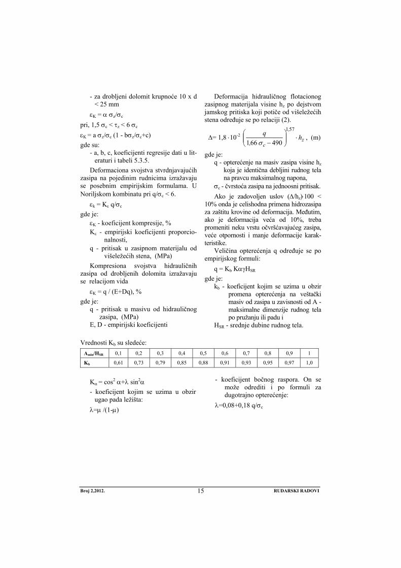
Deformacija hidrauličnog flotacionog zasipnog materijala visine hz po dejstvom jamskog pritiska koji potiče od višeležećih stena određuje se po relaciji (2).
Δ= 1,8 ⋅10-2 z
,
ch
,q
⋅⎟⎟⎠
⎞⎜⎜⎝
⎛−
571
490661 σ, (m)
gde je: q - opterećenje na masiv zasipa visine hz
koja je identična debljini rudnog tela na pravcu maksimalnog napona,
σc - čvrstoća zasipa na jednoosni pritisak. Ako je zadovoljen uslov (Δ/hz)⋅100 <
10% onda je celishodna primena hidrozasipa za zaštitu krovine od deformacija. Međutim, ako je deformacija veća od 10%, treba promeniti neku vrstu očvršćavajućeg zasipa, veće otpornosti i manje deformacije karak-teristike.
Veličina opterećenja q određuje se po empirijskog formuli:
q = Kb KαγHSR gde je:
kb - koeficijent kojim se uzima u obzir promena opterećenja na veštački masiv od zasipa u zavisnosti od A - maksimalne dimenzije rudnog tela po pružanju ili padu i
HSR - srednje dubine rudnog tela.
Vrednosti Kb su sledeće: Amin/HSR 0,1 0,2 0,3 0,4 0,5 0,6 0,7 0,8 0,9 1
Kb 0,61 0,73 0,79 0,85 0,88 0,91 0,93 0,95 0,97 1,0
Kα = cos2 α+λ sin2α - koeficijent kojim se uzima u obzir
ugao pada ležišta: λ=μ /(1-μ)
- koeficijent bočnog raspora. On se može odrediti i po formuli za dugotrajno opterećenje:
λ=0,08+0,18 q/σc
Broj 2,2012. RUDARSKI RADOVI
16
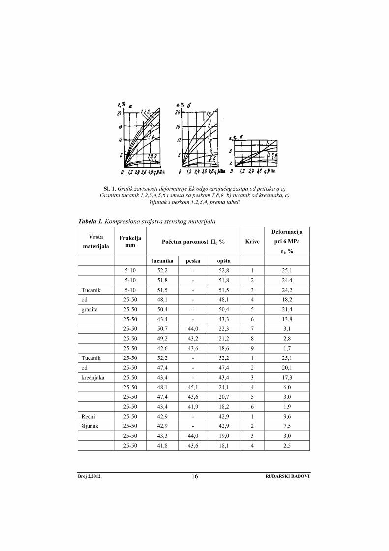
Sl. 1. Grafik zavisnosti deformacije Ek odgovarajućeg zasipa od pritiska q a) Granitni tucanik 1,2,3,4,5,6 i smesa sa peskom 7,8,9. b) tucanik od krečnjaka, c)
šljunak s peskom 1,2,3,4, prema tabeli
Tabela 1. Kompresiona svojstva stenskog materijala
Vrsta materijala
Frakcija mm Početna poroznost Π0 % Krive
Deformacija pri 6 MPa
εk %
tucanika peska opšta 5-10 52,2 - 52,8 1 25,1
5-10 51,8 - 51,8 2 24,4
Tucanik 5-10 51,5 - 51,5 3 24,2
od 25-50 48,1 - 48,1 4 18,2
granita 25-50 50,4 - 50,4 5 21,4
25-50 43,4 - 43,3 6 13,8
25-50 50,7 44,0 22,3 7 3,1
25-50 49,2 43,2 21,2 8 2,8
25-50 42,6 43,6 18,6 9 1,7
Tucanik 25-50 52,2 - 52,2 1 25,1
od 25-50 47,4 - 47,4 2 20,1
krečnjaka 25-50 43,4 - 43,4 3 17,3
25-50 48,1 45,1 24,1 4 6,0
25-50 47,4 43,6 20,7 5 3,0
25-50 43,4 41,9 18,2 6 1,9
Rečni 25-50 42,9 - 42,9 1 9,6
šljunak 25-50 42,9 - 42,9 2 7,5
25-50 43,3 44,0 19,0 3 3,0
25-50 41,8 43,6 18,1 4 2,5
Broj 2,2012. RUDARSKI RADOVI
17
Tabela 2. Koeficijenti sigurnosti Kate-gorija
objekata
Dopuštena deformacija
mm/m Kd - za ležišta
rudna ugljena
I 2,0 150 300 II 3,5 100 200 III 5,5 50 100
Tabela 3. Empirijski koeficijent regresije Zasipni
materijal frakcije
a b c
0-5 1,2 0,09 0,54 0-10 0,8 0,08 0,45 0-25 0,6 0,07 0,36
Deformacione karakteristike očvršćava-jućih zasipnih materijala pri jednoos-nom pritisku
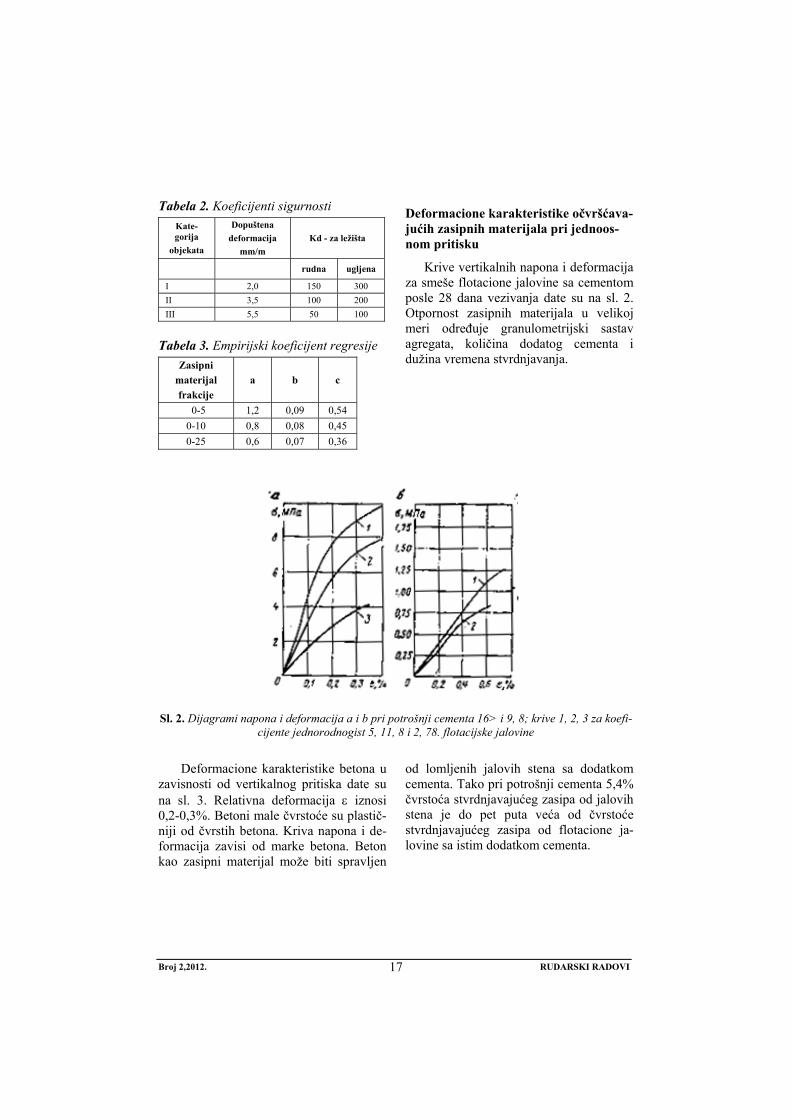
Krive vertikalnih napona i deformacija za smeše flotacione jalovine sa cementom posle 28 dana vezivanja date su na sl. 2. Otpornost zasipnih materijala u velikoj meri određuje granulometrijski sastav agregata, količina dodatog cementa i dužina vremena stvrdnjavanja.
Sl. 2. Dijagrami napona i deformacija a i b pri potrošnji cementa 16> i 9, 8; krive 1, 2, 3 za koefi-cijente jednorodnogist 5, 11, 8 i 2, 78. flotacijske jalovine
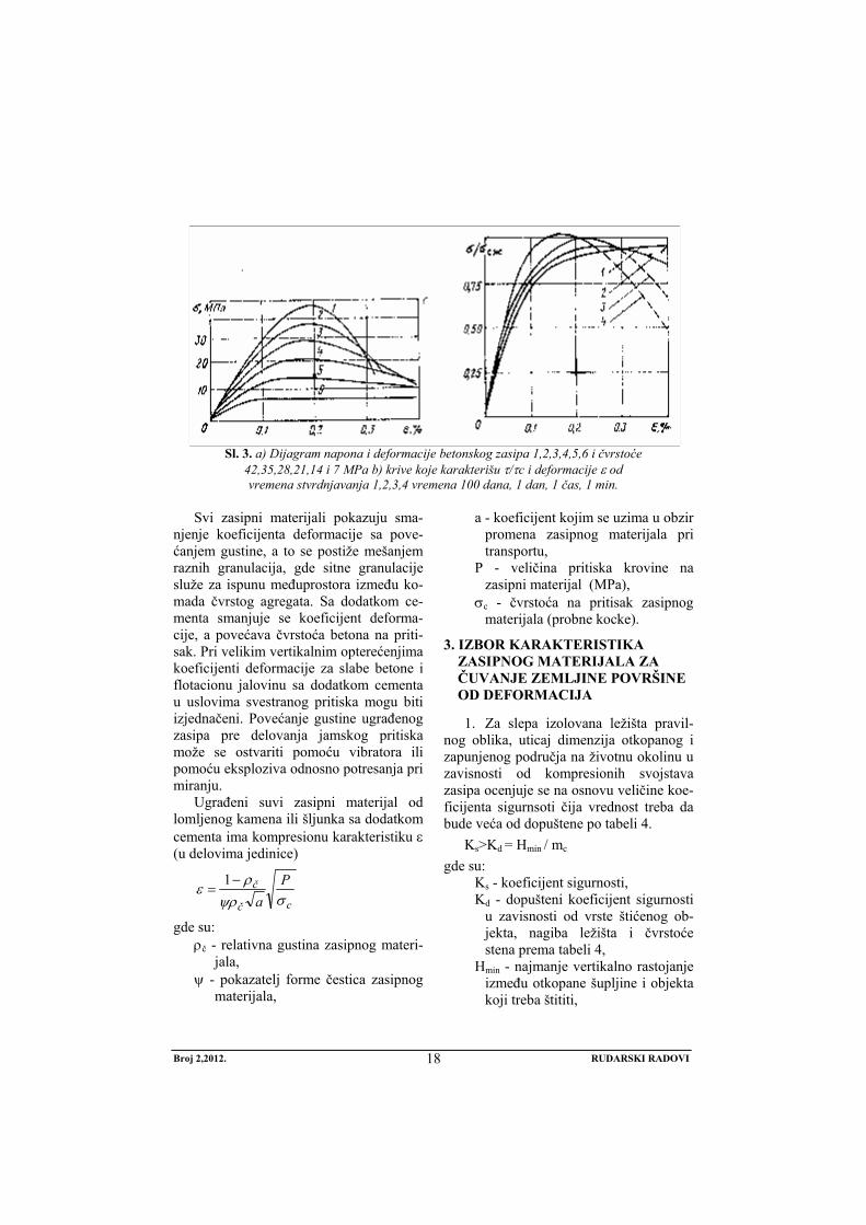
Deformacione karakteristike betona u
zavisnosti od vertikalnog pritiska date su na sl. 3. Relativna deformacija ε iznosi 0,2-0,3%. Betoni male čvrstoće su plastič-niji od čvrstih betona. Kriva napona i de-formacija zavisi od marke betona. Beton kao zasipni materijal može biti spravljen
od lomljenih jalovih stena sa dodatkom cementa. Tako pri potrošnji cementa 5,4% čvrstoća stvrdnjavajućeg zasipa od jalovih stena je do pet puta veća od čvrstoće stvrdnjavajućeg zasipa od flotacione ja-lovine sa istim dodatkom cementa.
Broj 2,2012. RUDARSKI RADOVI
18
Sl. 3. a) Dijagram napona i deformacije betonskog zasipa 1,2,3,4,5,6 i čvrstoće 42,35,28,21,14 i 7 MPa b) krive koje karakterišu τ/τc i deformacije ε od vremena stvrdnjavanja 1,2,3,4 vremena 100 dana, 1 dan, 1 čas, 1 min.
Svi zasipni materijali pokazuju sma-
njenje koeficijenta deformacije sa pove-ćanjem gustine, a to se postiže mešanjem raznih granulacija, gde sitne granulacije služe za ispunu međuprostora između ko-mada čvrstog agregata. Sa dodatkom ce-menta smanjuje se koeficijent deforma-cije, a povećava čvrstoća betona na priti-sak. Pri velikim vertikalnim opterećenjima koeficijenti deformacije za slabe betone i flotacionu jalovinu sa dodatkom cementa u uslovima svestranog pritiska mogu biti izjednačeni. Povećanje gustine ugrađenog zasipa pre delovanja jamskog pritiska može se ostvariti pomoću vibratora ili pomoću eksploziva odnosno potresanja pri miranju.
Ugrađeni suvi zasipni materijal od lomljenog kamena ili šljunka sa dodatkom cementa ima kompresionu karakteristiku ε (u delovima jedinice)
cč
č Pa σψρ
ρε −=
1
gde su: ρč - relativna gustina zasipnog materi-
jala, ψ - pokazatelj forme čestica zasipnog
materijala,
a - koeficijent kojim se uzima u obzir promena zasipnog materijala pri transportu,
P - veličina pritiska krovine na zasipni materijal (MPa),
σc - čvrstoća na pritisak zasipnog materijala (probne kocke).
3. IZBOR KARAKTERISTIKA ZASIPNOG MATERIJALA ZA ČUVANJE ZEMLJINE POVRŠINE OD DEFORMACIJA
1. Za slepa izolovana ležišta pravil-nog oblika, uticaj dimenzija otkopanog i zapunjenog područja na životnu okolinu u zavisnosti od kompresionih svojstava zasipa ocenjuje se na osnovu veličine koe-ficijenta sigurnsoti čija vrednost treba da bude veća od dopuštene po tabeli 4.
Ks>Kd = Hmin / mc gde su:
Ks - koeficijent sigurnosti, Kd - dopušteni koeficijent sigurnosti
u zavisnosti od vrste štićenog ob-jekta, nagiba ležišta i čvrstoće stena prema tabeli 4,
Hmin - najmanje vertikalno rastojanje između otkopane šupljine i objekta koji treba štititi,
Broj 2,2012. RUDARSKI RADOVI
19
mc-srednja debljina visina šupljine zaostala posle konsolidacije i sle-ganja zasipa pod pritiskom krovine, mc = ho + ε(m-ho).
Ako se uzme da je A =ho /m koefici-jent zapune otkopa onda je:
mc = m (1-A+εA), (m) m - debljina (visina) otkopanog dela
ležišta (horizonta ili više horizonata), ho-deo nezapunjenog dela otkopa u
poslednjem pojasu, ε - koeficijent kompresionih svojstava
zasipnog materijala pod opterećen-jem krovine.
Objekti na zemljinoj površini i površina neće biti izloženi deformacijama ako je zadovoljen uslov Hmin>mc⋅kb=Hp ili po Akimovu, u zavisnosti od dimenzija šupljine:
Hmin>Hp=K’ 300 ⋅ mc ⋅n /(n-74⋅ mc) gde su:
Hp - proračunska bezbedna dubina do gornje granice ležišta,
N - dužina horizontalne projekcije rudnog tela upravno na prostiranje L (pri n >L u formuli se umesto n može uzeti veličina (L+n)/2),
L - dužina rudnog tela po prostiranju K’ - koeficijent kojim se uzima u obzir
čvrstoća stena krovine i osetljivost objekata na površini. Orjentacione vrednosti K’ u zavisnosti od koefi-cijenta čvrstoće stena po M. M. Protodjakonovu su:
⎥⎦⎤
⎢⎣⎡
<>
0,8 0,9 ,1 ; K'9 9-5 ,5-2 ; f
Zadovoljavajući koeficijent kompre-sionih svojstava zasipnog materijala, pa sa tim i vrsta zasipnog materijala može se odrediti unošenjem izraza za određivanje mc .Sređivanjem prethodnih formula i izražavanjem eksplicitno ε dobijaju se formula: H=K’300 ⋅n (1-A+εA)m/[n-74 m(1-A+εA)] εdop = 1-A - Hn /(300 K’ n+74 H)mA
Zasip za ispunu otkopa ispod štićenih objekata mora imati manji koeficijent kompresije εk < (εdop), pa se u tabelama za razne vrste zasipa na osnovu njihovih kompresionih karakteristika može naći odgovarajuća vrsta zasipa.
2. Dopuštena karakteristika zasipa može biti određena i na osnovu poznatih dopuštenih horizontalnih deformacija zemljišta ispod objekata, na konturi uleg-nuća i nagiba, iz uslova:
ε < εdop ; i < i dop gde su:
ε, εdop; i, idop - odgovarajuće očekivane horizontalne deformacije i nagibi u okviru ulegnuća.
Dopuštene deformacije zasipa ispod štićene teritorije po uslovu ε<εdop određuje se po formul:
1110
21
3+−−=
−
Amh
Anncos'AmF
L H
)z(
dop
α
εε , (mm/m),
i po uslovu i < idop :
11
10
21
3
+−−
−=
Amh
A
nncosq'AmS
Li
H
o)z(
dop
αε
gde su: L - minimalna dužina polovine uleg-
nuća u m. Određuje se grafički na osnovu uglova sleganja (δ, γ, β),
α - ugao nagiba ležišta, εdop , idop - dopuštene horizontalne de-
formacije i nagibi ispod štićenih ob-jekata. One zavise od vrste objekata i njihovog značaja.
A - koeficijent zapunjavanja otkopa, m -debljina ležišta, F(z) - funkcija krive horizontalnih de-
formacija, S(z) - funkcija tipične krive naklona, qo - relativno sleganje qo=0,65-0,75,
Broj 2,2012. RUDARSKI RADOVI
20
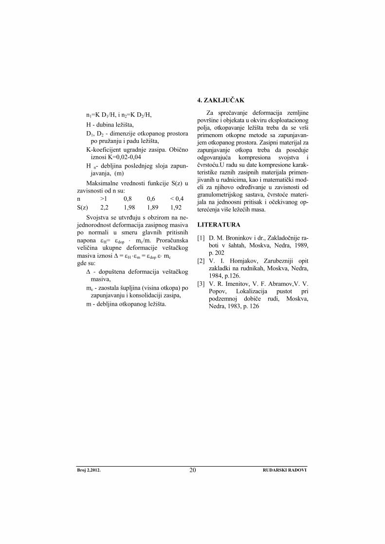
n1=K D1/H, i n2=K D2/H, H - dubina ležišta, D1, D2 - dimenzije otkopanog prostora
po pružanju i padu ležišta, K-koeficijent ugradnje zasipa. Obično
iznosi K=0,02-0,04 H n- debljina poslednjeg sloja zapun-
javanja, (m) Maksimalne vrednosti funkcije S(z) u
zavisnosti od n su: n >1 0,8 0,6 < 0,4 S(z) 2,2 1,98 1,89 1,92
Svojstva se utvrđuju s obzirom na ne-jednorodnost deformacija zasipnog masiva po normali u smeru glavnih pritisnih napona εH= εdop ⋅ mc/m. Proračunska veličina ukupne deformacije veštačkog masiva iznosi Δ = εH ⋅εm = εdop ε⋅ mc gde su:
Δ - dopuštena deformacija veštačkog masiva,
mc - zaostala šupljina (visina otkopa) po zapunjavanju i konsolidaciji zasipa,
m - debljina otkopanog ležišta.
4. ZAKLJUČAK
Za sprečavanje deformacija zemljine površine i objekata u okviru eksploatacionog polja, otkopavanje ležišta treba da se vrši primenom otkopne metode sa zapunjavan-jem otkopanog prostora. Zasipni materijal za zapunjavanje otkopa treba da poseduje odgovarajuća kompresiona svojstva i čvrstoću.U radu su date kompresione karak-teristike raznih zasipnih materijala primen-jivanih u rudnicima, kao i matematički mod-eli za njihovo određivanje u zavisnosti od granulometrijskog sastava, čvrstoće materi-jala na jednoosni pritisak i očekivanog op-terećenja više ležećih masa.
LITERATURA
[1] D. M. Broninkov i dr., Zakladočnije ra-boti v šahtah, Moskva, Nedra, 1989, p. 202
[2] V. I. Homjakov, Zarubezniji opit zakladki na rudnikah, Moskva, Nedra, 1984, p.126.
[3] V. R. Imenitov, V. F. Abramov,V. V. Popov, Lokalizacija pustot pri podzemnoj dobiče rudi, Moskva, Nedra, 1983, p. 126
No 2, 2012. MINING ENGINEERING
21
MINING AND METALLURGY INSTITUTE BOR YU ISSN: 1451-0162 COMMITTEE OF UNDERGROUND EXPLOITATION OF THE MINERAL DEPOSITS UDK: 622
UDK: 622:261.2:581.5:504.06 (045)=20
Miodrag Miljković*, Rodoljub Stanojlović*, Jovica Sokolović*
SAFETY AND DEFORMATION CHARACTERISTICS OF STOPING MATERIALS IN THE MINES**
Abstract
For achievement a complete efficiency of deposit without depletion of ore, with preservation of the Earth surface from deformations, the stope mining methods with backfilling are used, without leaving the safety pillars or with subsequent obtaining the safety pillars. For these purposes, back-filling of stope is done with necessary strength and deformation characteristics. The mathematical models are discussed in this work for selection the filling material depending on a function in the process of ore mining and after mining the deposit.
Keywords: stope filling, deformation characteristics, backfilling, environmental protection
* Corresponding author: Jovica Sokolović, University of Belgrade, Technical faculty Bor Vojske Jugoslavije 12, 19210, Bor, Serbia Tel.: +381 30 424 555; Fax: +381 30 421 078. E-mail address: [email protected] ** This paper presents the results of the Projects TR 33007, “Implementation of Modern Techical-
technological and Environmental Solutions in the Existing Production Systems of the Copper Mine Bor and Copper Mine Majdanpek” and TR 33038 “Improving the Technology of Copper Ore Mining and Processing with Monitoring of Living and Working Environment in RTB Bor Group”, funded by the Ministry of Education and Science of the Republic of Serbia. The au-thors are grateful to the Ministry for financial support.
1. INTRODUCTION
For filling the cavities, depending on the aim to be achieved using the selected variant of stope mining method, geometry and quality of the deposit, the appropriate
material for filling and technology of trans-portation and installation in excavated cavi-ties are selected [1]. Mining and geolo- gical conditions of deposit occur-
No 2, 2012. MINING ENGINEERING
22
rence and its quality (value of ore) and demands for preservation the environ-mental factors have influence on selection the stope mining method, and also on se-lection the material and filling technology [2]. Obtaining of deposit can be carried out in layers or benches, without living safety protective pillars or with safety pillars of ore and their subsequent obtain-ing between the pillars [3]. Mining of de-posit with backfilling of stopes with some kind of filling material can be done by the following stope mining methods:
1.Bench mining in descending steps by drifts of steep ore veins and movement of equipment on stoping
2.Single or multiple layer, panel, vertical or horizontal stoping
3.Sublevel stoping with subsequent backfilling of empty stopes
4.Chamber pillar stoping with or without living the roof
5.Chamber pillar stoping with ore stor-ages and subsequent filling after ore discharge and subsequent obtaining of pillars
Backfilling of stope in the mentioned stoping methods for clean ore stoping un-der the certain circumstances of geometry, mechanical characteristics of roof rocks, demands for preservation of earth surface and deposit depth, can be realized using the stoping material with adequate strength and deformation characteristics such as:
1. Dry stoping of crushed rock mate-rial of deposit surrounding rocks or transported from the earth’s surface ( with addition of bonding agent or without it)
2. Pneumatic stoping of crushed rock material, sand, ash with addition of bonding agent or by injection with bonding agents already fitted stop-ing mass.
3. Hydraulic stoping of hydro cyclone flotation waste rock, ashes from thermal power plants or sands with
addition of bonding materials or without them.
4. Special stoping of blocks of ice, expounding masses, frizzing water or combined by construction of ar-tificial pillars of stone or concrete blocks and filling the empty space between them by flotation tailings.
2. COMPRESSION CHARACTERISTICS OF STOPING MATERIALS IN STOPES
By compaction and volume reduction stoping materials can be divided into five groups as:
1. Highly resistant solidifying (concrete) stoping in which deformation does not exceed 3%.
2. Medium resistant solidifying stoping made of weak aggregate deformations of 2-5 %.
3. Combined massifs consisting of hard and loosely material or low resistant so-lidifying mixture with deformation characteristics of 5-10%.
4. Crushed rocks with little participation of small classes, with deformation char-acteristic of 10-15%.
5. Uniform crushed rocky material of low strength with deformation characteris-tics over 15%.
Deformation characteristic εk % of stoping is determined based on the reduc-tion of volume under the pressure. Load-ing is performed from the time of cessa-tion of deformation increase. Based on temporarily load and deformation it can be, depending on a type of stoping mate-rial, its grain-size distribution and installa-tion method, determined the functional dependence as:
εk% = f⋅σz /σe where:
σz - load, (MPa) σc - compressive strength of backfill,
(MPa)
No 2, 2012. MINING ENGINEERING
23
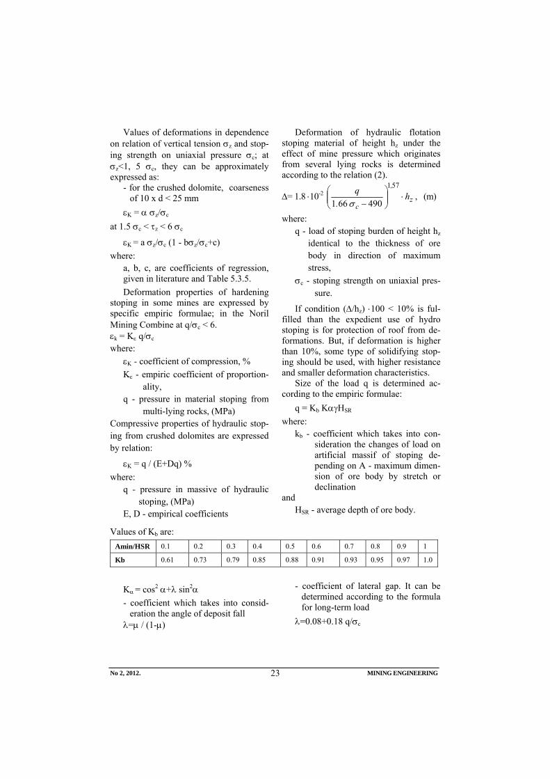
Values of deformations in dependence on relation of vertical tension σz and stop-ing strength on uniaxial pressure σc; at σz<1, 5 σc, they can be approximately expressed as:
- for the crushed dolomite, coarseness of 10 x d < 25 mm
εK = α σz/σc at 1.5 σc < τz < 6 σc
εK = a σz/σc (1 - bσz/σc+c) where:
a, b, c, are coefficients of regression, given in literature and Table 5.3.5. Deformation properties of hardening
stoping in some mines are expressed by specific empiric formulae; in the Noril Mining Combine at q/σc < 6. εk = Kε q/σc where:
εK - coefficient of compression, % Kε - empiric coefficient of proportion-
ality, q - pressure in material stoping from
multi-lying rocks, (MPa) Compressive properties of hydraulic stop-ing from crushed dolomites are expressed by relation:
εK = q / (E+Dq) % where:
q - pressure in massive of hydraulic stoping, (MPa)
E, D - empirical coefficients
Deformation of hydraulic flotation stoping material of height hz under the effect of mine pressure which originates from several lying rocks is determined according to the relation (2).
Δ= 1.8 ⋅10-2 z
,
ch
.q
⋅⎟⎟⎠
⎞⎜⎜⎝
⎛−
571
490661 σ, (m)
where: q - load of stoping burden of height hz
identical to the thickness of ore body in direction of maximum stress,
σc - stoping strength on uniaxial pres-sure.
If condition (Δ/hz) ⋅100 < 10% is ful-filled than the expedient use of hydro stoping is for protection of roof from de-formations. But, if deformation is higher than 10%, some type of solidifying stop-ing should be used, with higher resistance and smaller deformation characteristics.
Size of the load q is determined ac-cording to the empiric formulae:
q = Kb KαγHSR where:
kb - coefficient which takes into con-sideration the changes of load on artificial massif of stoping de-pending on A - maximum dimen-sion of ore body by stretch or declination
and HSR - average depth of ore body.
Values of Kb are: Amin/HSR 0.1 0.2 0.3 0.4 0.5 0.6 0.7 0.8 0.9 1
Kb 0.61 0.73 0.79 0.85 0.88 0.91 0.93 0.95 0.97 1.0
Kα = cos2 α+λ sin2α - coefficient which takes into consid-
eration the angle of deposit fall λ=μ / (1-μ)
- coefficient of lateral gap. It can be determined according to the formula for long-term load
λ=0.08+0.18 q/σc
No 2, 2012. MINING ENGINEERING
24
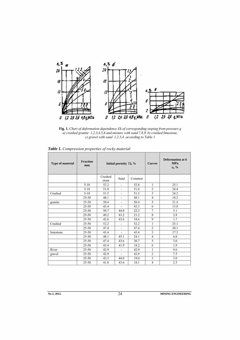
Fig. 1. Chart of deformation dependence Ek of corresponding stoping from pressure q a) crushed granite 1,2,3,4,5,6 and mixture with sand 7,8,9. b) crushed limestone,
c) gravel with sand 1,2,3,4, according to Table 1
Table 1. Compression properties of rocky material
Type of material Fraction mm Initial porosity Π0 % Curves
Deformation at 6 MPa εk %
Crushed stone Sand Common
5-10 52.2 - 52.8 1 25.1 5-10 51.8 - 51.8 2 24.4 Crushed 5-10 51.5 - 51.5 3 24.2 25-50 48.1 - 48.1 4 18.2 granite 25-50 50.4 - 50.4 5 21.4 25-50 43.4 - 43.3 6 13.8 25-50 50.7 44.0 22.3 7 3.1 25-50 49.2 43.2 21.2 8 2.8 25-50 42.6 43.6 18.6 9 1.7 Crushed 25-50 52.2 - 52.2 1 25.1 25-50 47.4 - 47.4 2 20.1 limestone 25-50 43.4 - 43.4 3 17.3 25-50 48.1 45.1 24.1 4 6.0 25-50 47.4 43.6 20.7 5 3.0 25-50 43.4 41.9 18.2 6 1.9 River 25-50 42.9 - 42.9 1 9.6 gravel 25-50 42.9 - 42.9 2 7.5 25-50 43.3 44.0 19.0 3 3.0 25-50 41.8 43.6 18.1 4 2.5
No 2, 2012. MINING ENGINEERING
25
Table 2. Coefficient of safety
Category of object
Allowed deformation
mm/m Kd - for layers
ore coal I 2.0 150 300 II 3.5 100 200 III 5.5 50 100
Table 3. Empirical coefficient of regression
Fraction of stoping mate-
rial a b c
0-5 1.2 0.09 0.54 0-10 0.8 0.08 0.45 0-25 0.6 0.07 0.36
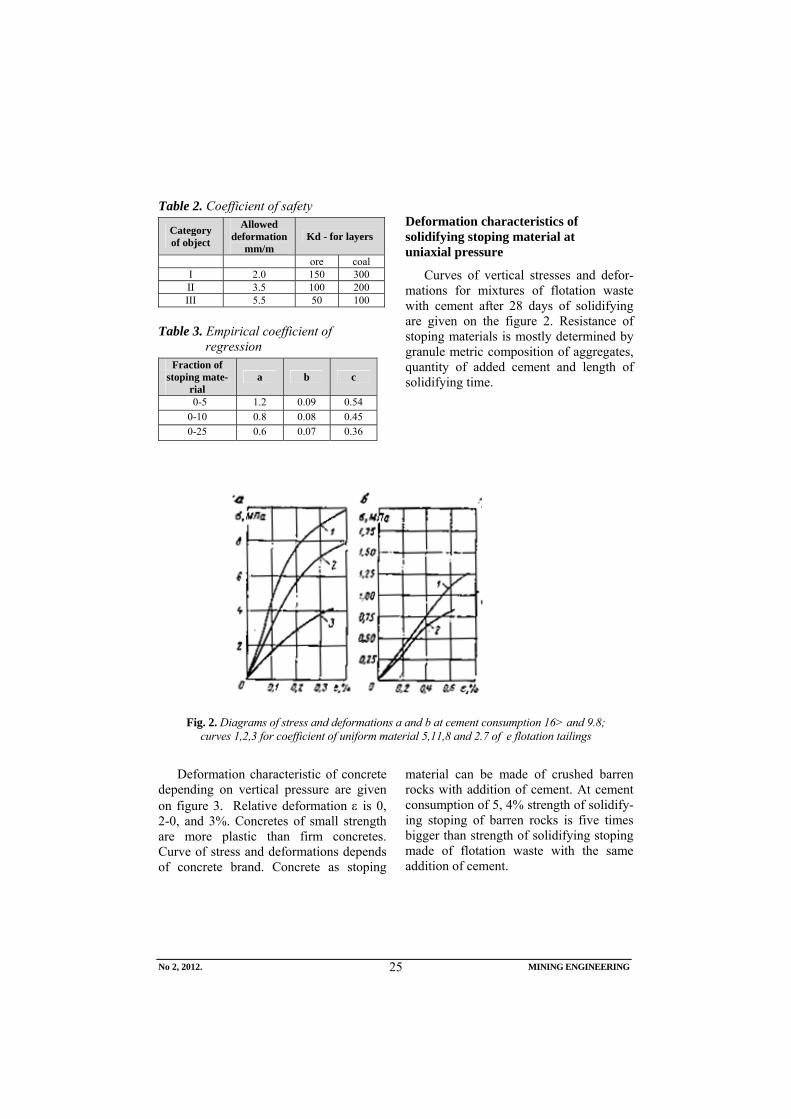
Deformation characteristics of solidifying stoping material at uniaxial pressure
Curves of vertical stresses and defor-mations for mixtures of flotation waste with cement after 28 days of solidifying are given on the figure 2. Resistance of stoping materials is mostly determined by granule metric composition of aggregates, quantity of added cement and length of solidifying time.
Fig. 2. Diagrams of stress and deformations a and b at cement consumption 16> and 9.8; curves 1,2,3 for coefficient of uniform material 5,11,8 and 2.7 of e flotation tailings
Deformation characteristic of concrete
depending on vertical pressure are given on figure 3. Relative deformation ε is 0, 2-0, and 3%. Concretes of small strength are more plastic than firm concretes. Curve of stress and deformations depends of concrete brand. Concrete as stoping
material can be made of crushed barren rocks with addition of cement. At cement consumption of 5, 4% strength of solidify-ing stoping of barren rocks is five times bigger than strength of solidifying stoping made of flotation waste with the same addition of cement.
No 2, 2012. MINING ENGINEERING
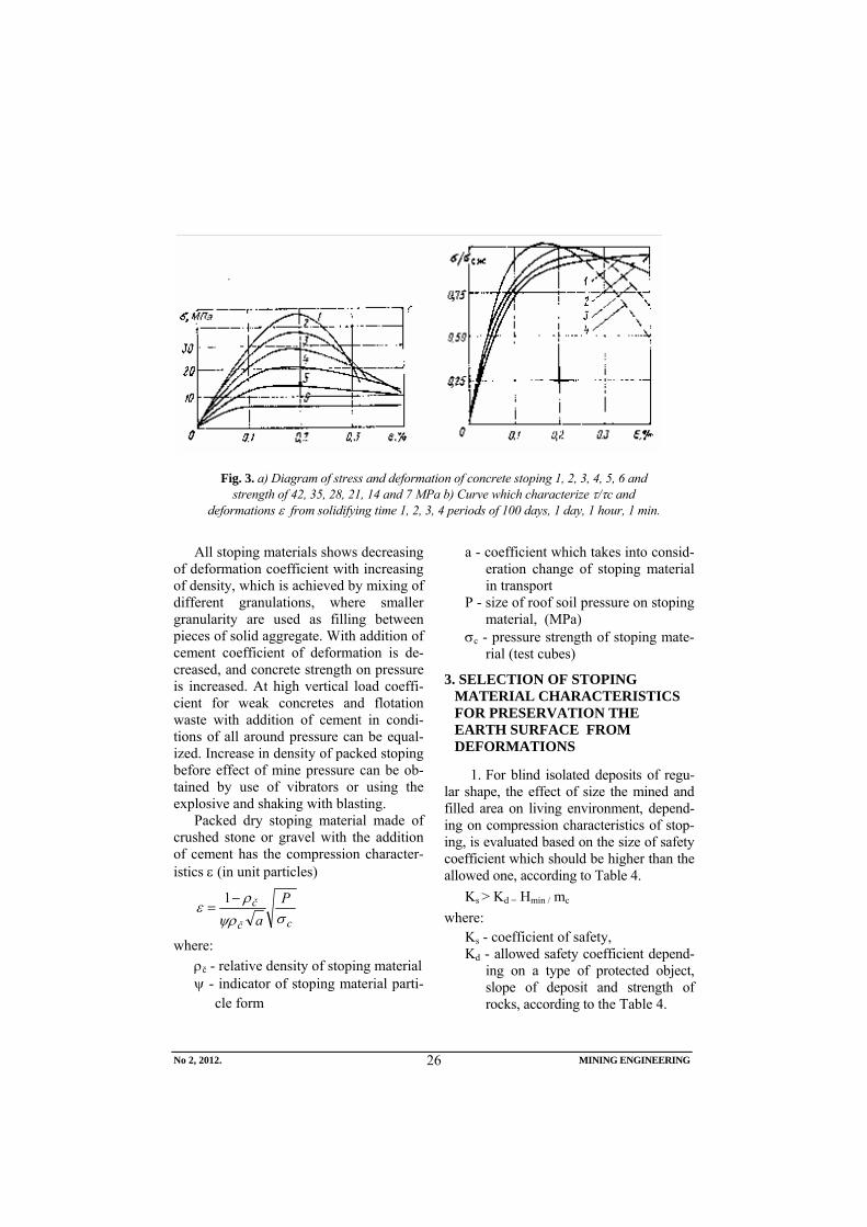
26
Fig. 3. a) Diagram of stress and deformation of concrete stoping 1, 2, 3, 4, 5, 6 and strength of 42, 35, 28, 21, 14 and 7 MPa b) Curve which characterize τ/τc and
deformations ε from solidifying time 1, 2, 3, 4 periods of 100 days, 1 day, 1 hour, 1 min.
All stoping materials shows decreasing
of deformation coefficient with increasing of density, which is achieved by mixing of different granulations, where smaller granularity are used as filling between pieces of solid aggregate. With addition of cement coefficient of deformation is de-creased, and concrete strength on pressure is increased. At high vertical load coeffi-cient for weak concretes and flotation waste with addition of cement in condi-tions of all around pressure can be equal-ized. Increase in density of packed stoping before effect of mine pressure can be ob-tained by use of vibrators or using the explosive and shaking with blasting.
Packed dry stoping material made of crushed stone or gravel with the addition of cement has the compression character-istics ε (in unit particles)
cč
č Pa σψρ
ρε
−=
1
where: ρč - relative density of stoping material ψ - indicator of stoping material parti-
cle form
a - coefficient which takes into consid-eration change of stoping material in transport
P - size of roof soil pressure on stoping material, (MPa)
σc - pressure strength of stoping mate-rial (test cubes)
3. SELECTION OF STOPING MATERIAL CHARACTERISTICS FOR PRESERVATION THE EARTH SURFACE FROM DEFORMATIONS
1. For blind isolated deposits of regu-lar shape, the effect of size the mined and filled area on living environment, depend-ing on compression characteristics of stop-ing, is evaluated based on the size of safety coefficient which should be higher than the allowed one, according to Table 4.
Ks > Kd = Hmin / mc where:
Ks - coefficient of safety, Kd - allowed safety coefficient depend-
ing on a type of protected object, slope of deposit and strength of rocks, according to the Table 4.
No 2, 2012. MINING ENGINEERING
27
Hmin - minimum vertical distance be-tween mined cavity and protected object,
mc - average thickness, height of resid-ual cavity after consolidation and subsidence of stoping under pres-sure of roof soil, mc = ho + ε(m-ho).
If A =ho /m is taken as coefficient of
stope filling than: mc = m (1-A+εA), (m) m - thickness (height) of mined part of
deposit (horizon or several hori-zons)
ho - part of unfilled section of stope in the last zone,
ε - coefficient of compression features of stoping material under the pres-sure of roof soil.
Objects on the Earth’ surface and sur-face will not be exposed to deformation if the condition is fulfilled Hmin>mc⋅kb=Hp or according to Akimov, depending on the cavity dimension Hmin>Hp=K’ 300 ⋅ mc ⋅n /(n-74⋅ mc) where:
Hp - calculated safety depth up to the upper border of layer
N - length of horizontal projection of the ore body perpendicular to the spreading L (at n >L in formula instead of n, the value (L+n)/2) can be taken
L - length of ore body to the spreading K’ - coefficient which takes into ac-
count the strength of roof rocks and sensitivity of structures on the sur-face.
Approximate values of K’ depending on a coefficient of strength for rocks ac-cording to the author of this article.
According to Protodjakonov, they are:
⎥⎦⎤
⎢⎣⎡
<>
0.8 0.9 ,1 ; K'9 9-5 ,5-2 ; f
Satisfying coefficient of compression properties of stoping material, and also stoping material itself can be determined using the expression for determination of mc. By arrangement the previous formula and explicit expression of ε, the following formulae are obtained: H=K’300⋅n (1-A+εA)m/[n-74 m(1-A+εA)]
εdop = 1-A - Hn /(300 K’ n+74 H)mA
Stoping for filling of stopes under pro-tected objects must have smaller coeffi-cient of compression εk<(εdop), and in Ta-bles for different types of stoping based in their compression characteristics can find the suitable type of stoping material.
2. Allowed characteristic of stoping can be also determined based on known allowed horizontal deformations of the ground under objects, on the contour of depressions and slopes, from condition:
ε < εdop ; i < i dop where:
ε, εdop; i, idop - corresponding and ex-pecting horizontal deformations and slopes within the depres-sions.
Permissible deformations of stoping under protected territory according to the condition ε<εdop are determined by formu-lae:
11
10
21
3
+−−
−=−
Amh
A
nncos'AmF
L
H
)z(
dop
α
εε
, (mm/m)
And condition i < idop :
11
10
21
3
+−−
−=
Amh
A
nncosq'AmS
Li
H
o)z(
dop
αε
where: L - minimum length of half depression in
m. It is determined graphically based on angles of subsidence (δ, γ,β)
No 2, 2012. MINING ENGINEERING
28
α - subsidence angle of layer εdop , idop - permitted horizontal defor-
mations and slopes under protected objects. They depend on a type of object and their importance.
A - coefficient of filling of stope m - thickness of the layer F(z) - function of horizontal deforma-
tion curve S(z) - function of typical inclination
curve, qo - relative subsidence qo=0,65-0,75 n1=K D1/H, and n2=K D2/H, H - layer depth , D1, D2 - dimension of excavated space
to the spreading and fall of the layer, K - coefficient of installation of stop-
ing. It is usually K=0.02-0.04 H n- thickness of last layer of stoping,
(m) Maximum values of function S(z) de-
pending of n are: n >1 0.8 0.6 < 0.4
S(z) 2.2 1.98 1.89 1.92
Properties are determined due to ine-quality of deformations of stoping massive across the normal in direction of main pushing stresses εH= εdop ⋅ mc/m. Calcu-lated value of total deformation of the artificial massive is Δ = εH ⋅εm = εdop ε⋅ mc where:
Δ - allowed deformation of artificial massive,
mc - residual cavity (height of stope) after filling and consolidation of stoping
m - thickness of excavated layer
4. CONCLUSION
To prevent deformations of the Earth surface and objects in the area of exploita-tion field, excavation of ore layer should be done by use of stoping method with backfilling of excavated space. Stoping material for filling of stope should have the appropriate compression features and strength. In this article are given compres-sion characteristics of different stoping materials applied in mines, and mathe-matical models for their determination in dependence of granulometric composition, strength of material on uniaxial pressure and expected stress of several laying masses.
REFERENCES
[1] D. M. Broninkov et al., Backfill Works in the Mines, Moscow, Nedra, 1989, pp. 202 (in Russian);
[2] V. I. Homjakov, Zarubezniji opit zakladki na rudnikah, Moscow, Nedra, 1984, pp. 126 (in Russian);
[3] V. R. Imenitov, V. F. Abramov,V. V. Popov, Localization of Emptiness in Underground Ore Mining, Moscow, Nedra, 1983, pp. 126 (in Russian).
Broj 2,2012. RUDARSKI RADOVI
29
INSTITUT ZA RUDARSTVO I METALURGIJU BOR YU ISSN: 1451-0162 KOMITET ZA PODZEMNU EKSPLOATACIJU MINERALNIH SIROVINA UDK: 622
UDK: 624.12:624.02(045)=861
Ratomir Popović*, Milenko Ljubojev*, Dragan Ignjatović*, Lidija Đurđevac Ignjatović*
VIBRACIJE TEMELJA NA ELASTO-PLASTIČNOJ OSNOVI PRI KONSTANTNO DELUJUĆOJ I PERIODIČNOJ SILI**
Izvod
U radu se analizira nelinearno stanje napon-deformacija pri konstantno delujućem opterećenju i sa periodičnim dejstvom. Rešenja se izvode za oblast elastičnih deformacija tj. Do stanja tla na granici proporcionalnosti i za elastoplastičnu oblast iza granice proporcionalnosti.
Ključne reči: vibracija, frekvencija, napon proporcionalnosti, brzina, ubrzanje
* Institut za rudarstvo i metalurgiju Bor ** Ovaj rad je proistekao iz Projekta broj 33021 „Istraživanje i praćenje promena naponsko
deformacionog stanja u stenskom masivu“ in-situ“ oko podzemnih prostorija sa izradom modela sa posebnim osvrtom na tunel Kriveljske reke i Jame Bor“, koga finansira Ministarstvo za prosvetu i nauku Republike Srbije
1. UVOD
Pri proračunu statički neodređenih sistema, sile se određuju na bazi jednačina deformabilnosti međusobno povezanih sila i pomeranje, ne obraćajući pažnju da i pri određivanju bočnog pritiska tla, takođe predstavlja svojevrsni statički neodređen problem, jer nema funkcionalne veze izme-đu sila i pomeranja. Iz navedenog razloga u radu se analizira zavisnost između verifiko-vanog napona promenljivog intenziteta i sleganja temelja koja je predstavljena u obliku bilinearnog zakona.
Osim uspostavljenih sila, sile inercije temelja, uzima se u obzir i sila otpora nastala u obliku početnog trenja u tlu.
Nelinearna zavisnost napon-deformacija
se razdvaja u dva dela. Prvi elastični deo se razmatra do granice proporcionalnosti, a druga oblast elastoplastičnog stanja se razmatra sa novom ishodišnom tačkom.
2. DEJSTVO KONSTANTNE SILE
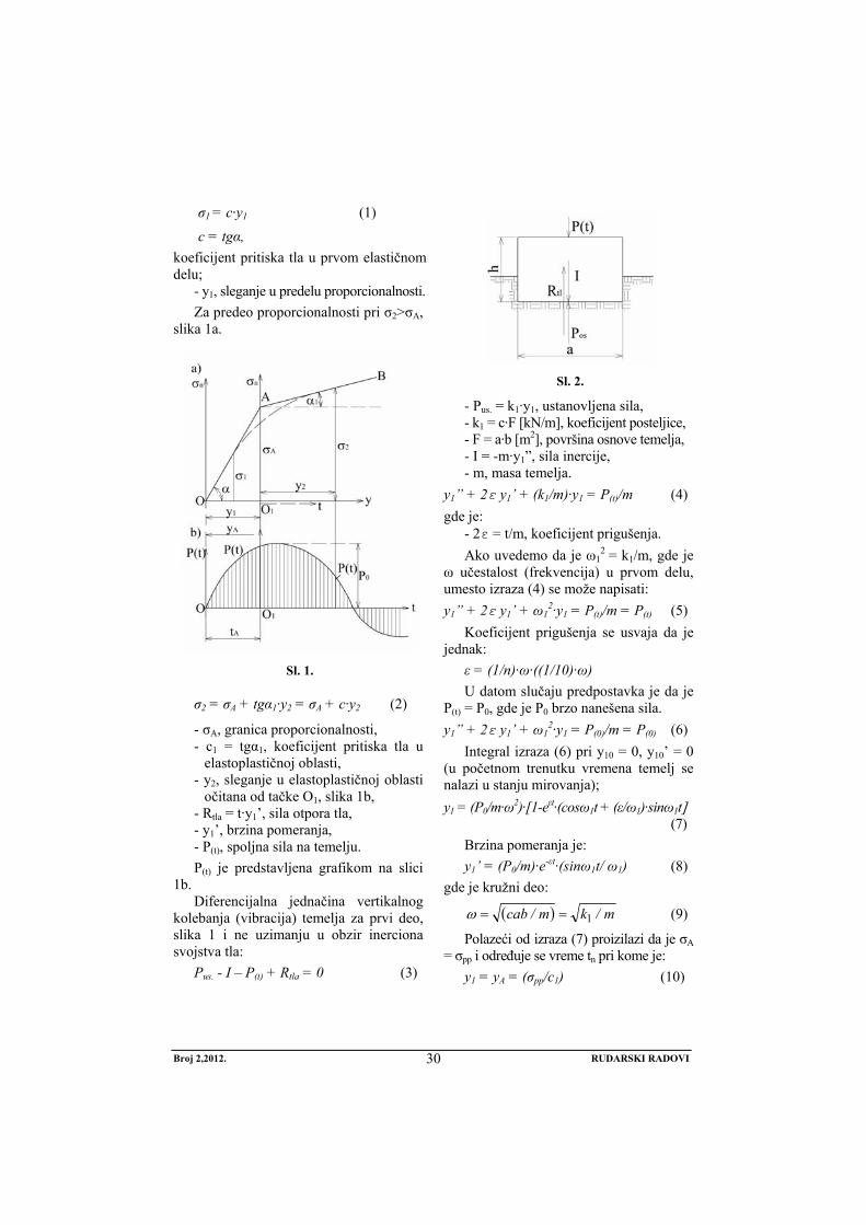
Pravougli, masivni temelj, oslonjen na tlo sa elastoplastičnim svojstvima i nelinearnom zavisnošću napon-sleganje (deformacija) izlo-žen je vibriranju (oscilovanju). Inerciona svoj-stva osnove za sad zanemarujemo. Zavisnost između vertikalnog napona na osnovu σn i sle-ganja y, slika 1a, predstavljen je u vidu bili-nearnog zakona do granice proporcionalnosti.
Broj 2,2012. RUDARSKI RADOVI
30
σ1 = c·y1 (1)
c = tgα, koeficijent pritiska tla u prvom elastičnom delu;
- y1, sleganje u predelu proporcionalnosti. Za predeo proporcionalnosti pri σ2>σA,
slika 1a.
Sl. 1.
σ2 = σA + tgα1·y2 = σA + c·y2 (2)
- σA, granica proporcionalnosti, - c1 = tgα1, koeficijent pritiska tla u
elastoplastičnoj oblasti, - y2, sleganje u elastoplastičnoj oblasti
očitana od tačke O1, slika 1b, - Rtla = t·y1’, sila otpora tla, - y1’, brzina pomeranja, - P(t), spoljna sila na temelju. P(t) je predstavljena grafikom na slici
1b. Diferencijalna jednačina vertikalnog
kolebanja (vibracija) temelja za prvi deo, slika 1 i ne uzimanju u obzir inerciona svojstva tla:
Pus. - I – P(t) + Rtla = 0 (3)
Sl. 2.
- Pus. = k1·y1, ustanovljena sila, - k1 = c·F [kN/m], koeficijent posteljice, - F = a·b [m2], površina osnove temelja, - I = -m·y1”, sila inercije, - m, masa temelja.
y1” + 2ε y1’ + (k1/m)·y1 = P(t)/m (4) gde je:
- 2ε = t/m, koeficijent prigušenja. Ako uvedemo da je ω1
2 = k1/m, gde je ω učestalost (frekvencija) u prvom delu, umesto izraza (4) se može napisati: y1” + 2ε y1’ + ω1
2·y1 = P(t)/m = P(t) (5) Koeficijent prigušenja se usvaja da je
jednak: ε = (1/n)·ω·((1/10)·ω) U datom slučaju predpostavka je da je
P(t) = P0, gde je P0 brzo nanešena sila. y1” + 2ε y1’ + ω1
2·y1 = P(0)/m = P(0) (6) Integral izraza (6) pri y10 = 0, y10’ = 0
(u početnom trenutku vremena temelj se nalazi u stanju mirovanja); y1 = (P0/m·ω2)·[1-eεt·(cosω1t + (ε/ω1)·sinω1t] (7)
Brzina pomeranja je: y1’ = (P0/m)·e-εt·(sinω1t/ ω1) (8)
gde je kružni deo:
( ) m/km/cab 1==ω (9)
Polazeći od izraza (7) proizilazi da je σA = σpp i određuje se vreme tn pri kome je:
y1 = yA = (σpp/c1) (10)
Broj 2,2012. RUDARSKI RADOVI
31
gde je: - σpp granica proporcionalnosti. Za drugi elastoplastični deo koristimo
nove koordinatne ose, slika 1a, i sa koordinatnim početkom u tački O1 i tada koristimo izraz (2) za σ2. Tada je uspostavljena sila P2:
P2 = σ2·F = σA·F + c1·F·y2 = c·F·y2 = = k1·yA + k2·yA
Diferencijalna jednačina kolebanja (vibracija) je:
(k1·yA + k2·yA) + t1·y2’ + m·y2’’ = P(t)
y2” + 2·ε· y2’ + ω22·y2 =
= (P(t) - k1·yA)/m = P1(t)/m Nastala sila ima drugi izraz: P1(t) = P(t) - k1·yA = P0 - k1·yA (11) Sada nova frekvencija (kolebanje) ima
sledeću vrednost:
⎪⎪⎭
⎪⎪⎬
⎫
+=
==
21
222
12
εωω
ω
'
mabc
mk
(12)
Sada je koeficijent prigušenja:
211 ωε ⋅=n
Konačna diferencijalna jednačina frekvencije (kolebanja) drugog dela dijagrama, slika 1, je:
y2” + 2·ε1· y2’ + ω22·y2 =
= (P0 - k1·yA)/m = P1(t)/m (13) Integral izraza (13), uzevši u obzir da
je t1=0, tačka O1, dijagram slika 1a, od-stranjen je yA, i gde je yA' brzina:
⎥⎦
⎤⎢⎣
⎡⎟⎟⎠
⎞⎜⎜⎝
⎛+−⋅
⋅−+
+⎟⎟⎠
⎞⎜⎜⎝
⎛+=
−
−
−
tsintcose
Psiney
tsintcoseyy
''
't
'
't'
A
''
'tA
22
12
22
1
2
2
22
122
1
1
1
1 ωωεω
ωωω
ωωεω
ε
ε
ε
(14)
Brzina pomeranja je:
'
't
't'
A
''
't'A
'
tsinePtsiney
tsintcoseyy
2
212
2
22
22
122
11
1
ωωω
ω
ω
ωωεω
εε
ε
−−
−
+−
−⎟⎟⎠
⎞⎜⎜⎝
⎛+=
(15)
Maksimalni otklon određen je priraštajem brzine po izrazu (15).
3. DEJSTVO PERIODIČNE SILE
Diferencijalna jednačina vibracija za prvi deo dijagrama, slika 1b, umesto izraza (4), a pri početnom prigušenju, je sledeća: y1” + 2·ε· y1’ + ω1
2·y1 = P0 sin(θt+λ) (16) gde je:
- P0, amplituda sile. P0/m [m/s], m = P/g [kNs2/m]
gde je: - m, masa temelja - g = 9,806 [m/s2], ubrzanje zemljine
teže, - ε, koeficijent prigušenja, određen kao
n-ti deo sopstvenih vibracija, - y1, vertikalno pomeranje centra podloge
temelja u elastičnoj oblasti (t≤tA), - λ, početni stadijum dejstva periodične
sile (u prvom delu se uzima λ = 0). Pun integral diferencijalnog izraza (16)
a pri početnim uslovima t = 0, y1 = y0 i y1' = y0, ima sledeći oblik:
( ){ ( )[ ]
( ) ( ) }tsincossine
tcossinetsinz
P
tsinytsintcosyey
t
t
't
111111
111
0
1
101
1
1101
1
1
1
ωδλωθδλ
ωε
ωδλδλθ
ωω
ωωε
ω
ε
ε
ε
⎥⎦
⎤⎢⎣
⎡+++−
+−+++
+⎥⎦
⎤⎢⎣
⎡+⎟⎟⎠
⎞⎜⎜⎝
⎛+=
−
−
−
(17) gde je:
z1 = (ω12-θ2)2 + 4 θ2ε1
2; ε1 = (1/n)·ω1.
Broj 2,2012. RUDARSKI RADOVI
32
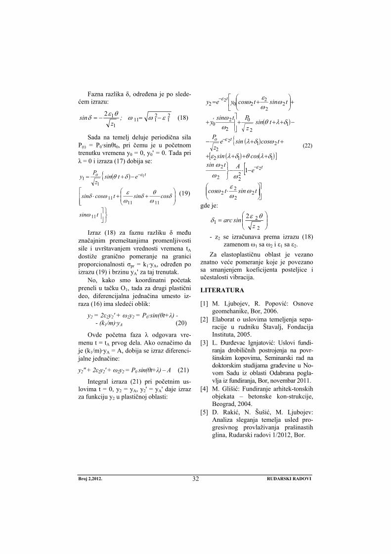
Fazna razlika δ, određena je po slede-ćem izrazu:
21
2111
1
12 εωωθεδ −=−= ;z
sin (18)
Sada na temelj deluje periodična sila P(t) = P0·sinθt0, pri čemu je u početnom trenutku vremena y0 = 0, y0' = 0. Tada pri λ = 0 i izraza (17) dobija se:
( ){
⎭⎬⎫
⎥⎦
⎤⎢⎢⎣
⎡⎟⎟⎠
⎞⎜⎜⎝
⎛++⋅
−+= −
tsin
cossintcossin
etsinz
Py to
11
111111
11 1
ω
δωθδ
ωεωδ
δθ ε
(19)
Izraz (18) za faznu razliku δ među značajnim premeštanjima promenljivosti sile i uvrštavanjem vrednosti vremena tA dostiže granično pomeranje na granici proporcionalnosti σpr = k1·yA, određen po izrazu (19) i brzinu yA' za taj trenutak.
No, kako smo koordinatni početak preneli u tačku O1, tada za drugi plastični deo, diferencijalna jednačina umesto iz-raza (16) ima sledeći oblik:
y2 = 2ε2y2' + ω2y2 = P0·sin(θt+λ) - - (k1/m)·yA (20)
Ovde početna faza λ odgovara vre-menu t = tA prvog dela. Ako označimo da je (k1/m)·yA = A, dobija se izraz diferenci-jalne jednačine:
y2" + 2ε2y2' + ω2y2 = P0 sin(θt+λ) – A (21)
Integral izraza (21) pri početnim us-lovima t = 0, y2 = yA, y2' = yA' daje izraz za funkciju y2 u plastičnoj oblasti:
( )
( ){( ) ( )[ ]
[
⎥⎦
⎤⎟⎟⎠
⎞⎜⎜⎝
⎛⋅
−⋅−⎭⎬⎫
++++
++−
−+++⎥⎥⎦
⎤+
⎢⎣
⎡+⎟⎟⎠
⎞⎜⎜⎝
⎛+=
−
−
−
tsintcos
eAtsincossin
tcossinezP
tsinzPtsin
y
tinstcosyey
t
to
'
t
22
22
222
2
112
212
12
0
2
20
22
2202
2
2
2
1
ωωε
ω
ωω
ωδλθδλε
ωδλ
δλθωω
ωωε
ω
ε
ε
ε
(22)
gde je:
⎟⎟⎠
⎞⎜⎜⎝
⎛=
2
21
2z
sinarc θεδ
- z2 se izračunava prema izrazu (18) zamenom ω1 sa ω2 i ε1 sa ε2.
Za elastoplastičnu oblast je vezano znatno veće pomeranje koje je povezano sa smanjenjem koeficijenta posteljice i učestalosti vibracija.
LITERATURA
[1] M. Ljubojev, R. Popović: Osnove geomehanike, Bor, 2006.
[2] Elaborat o uslovima temeljenja sepa-racije u rudniku Štavalj, Fondacija Instituta, 2005.
[3] L. Đurđevac Ignjatović: Uslovi fundi-ranja drobiličnih postrojenja na povr-šinskim kopovima, Seminarski rad na doktorskim studijama građevine u No-vom Sadu iz oblasti Odabrana pogla-vlja iz fundiranja, Bor, novembar 2011.
[4] M. Glišić: Fundiranje arhitek-tonskih objekata – betonske kon-strukcije, Beograd, 2004.
[5] D. Rakić, N. Šušić, M. Ljubojev: Analiza sleganja temelja usled pro-gresivnog provlaživanja prašinastih glina, Rudarski radovi 1/2012, Bor.
No 2, 2012. MINING ENGINEERING
33
MINING AND METALLURGY INSTITUTE BOR YU ISSN: 1451-0162 COMMITTEE OF UNDERGROUND EXPLOITATION OF THE MINERAL DEPOSITS UDK: 622
UDK: 624.12:624.02(045)=20
Ratomir Popović*, Milenko Ljubojev*, Dragan Ignjatović*, Lidija Đurđevac Ignjatović*
VIBRATIONS OF FOUNDATION ON ELASTIC-PLASTIC BASE AT CONSTANT AND PERIODICAL ACTING FORCE**
Abstract
This paper analyzes the nonlinear stress-strain state at constant applied loads and periodic ef-fect. The solutions are carried out in the field of elastic deformations, i.e. to the soil condition at proportionality limit and elastoplastic area beyond the proportionality limit.
Keywords: vibration, frequency, proportionality stress, rate, acceleration
* Mining and Metallurgy Institute Bor, 35 Zeleni bulevar, 19210 Bor ** This paper is produced from the project no. 33021 “Researching and monitoring changes in
stress-deformation condition of rock massif “in-situ” around undergraund facilities with devel-opment of model with special emphasis on Krivelj river tunnel and Bor pit”, which is funded by means of the Ministry of Education and Science of the Republic of Serbia
1. INTRODUCTION
In calculation the statically undetermi-nated systems, the forces are determined based on deformation equations of interre-lated forces and movement, not paying attention to and in determination the lat-eral pressure of soil, also presents a stati-cally undetermined problem, because there is no functional relationship between force and movement. For this reason, this paper analyzes the relationship between the verified stress of variable intensity and foundation settlement, which is repre-sented as a bilinear law.
In addition to the established powers, the forces of foundation inertia, the resis-
tance force, created in the form of initial friction in the soil, is taken into account.
Non-linear stress-strain dependence is separated into two parts. The first elastic is considered to the limit of proportionality, and the second area elastoplastic condition is considered with the new starting point.
2. EFFECT OF CONSTANT FORCE
Rectangular, solid foundation, resting on the elastoplastic properties and non-linear dependence of sress-subsidence (strain) is exposed to vibration (oscillation). The iner-tion properties are neglected for now.
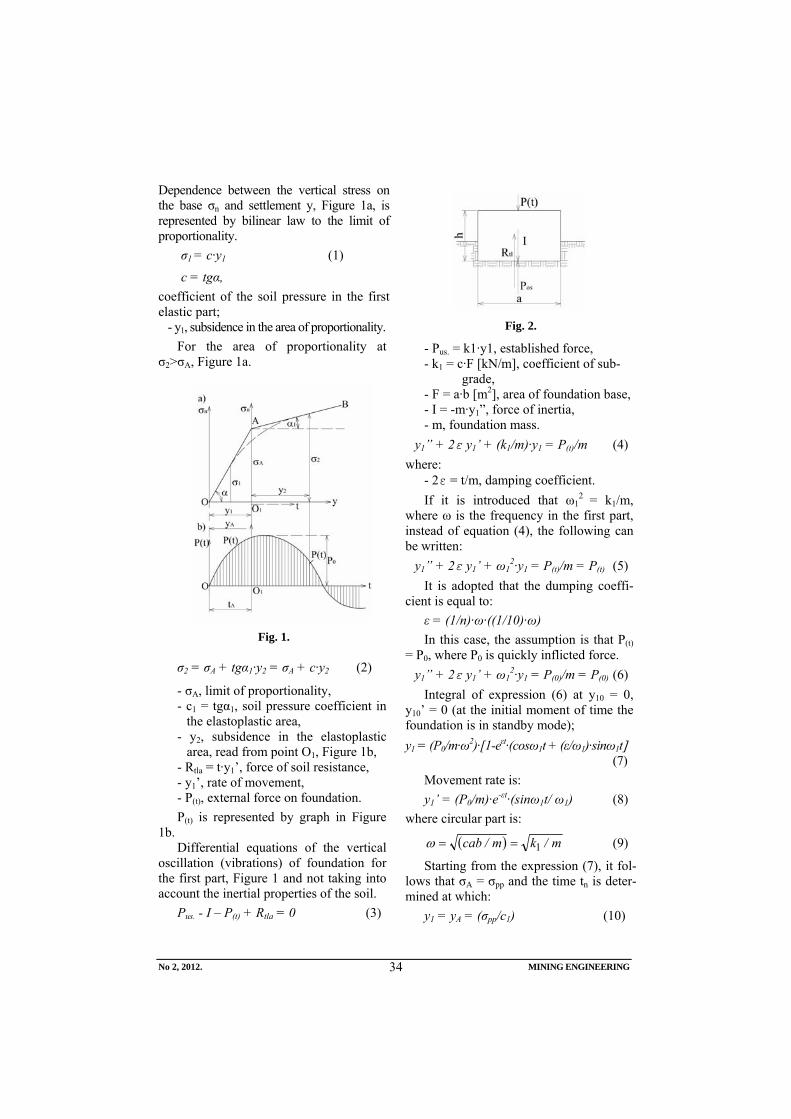
No 2, 2012. MINING ENGINEERING
34
Dependence between the vertical stress on the base σn and settlement y, Figure 1a, is represented by bilinear law to the limit of proportionality.
σ1 = c·y1 (1)
c = tgα, coefficient of the soil pressure in the first elastic part;
- y1, subsidence in the area of proportionality. For the area of proportionality at
σ2>σA, Figure 1a.
Fig. 1.
σ2 = σA + tgα1·y2 = σA + c·y2 (2)
- σA, limit of proportionality, - c1 = tgα1, soil pressure coefficient in
the elastoplastic area, - y2, subsidence in the elastoplastic
area, read from point O1, Figure 1b, - Rtla = t·y1’, force of soil resistance, - y1’, rate of movement, - P(t), external force on foundation. P(t) is represented by graph in Figure
1b. Differential equations of the vertical
oscillation (vibrations) of foundation for the first part, Figure 1 and not taking into account the inertial properties of the soil.
Pus. - I – P(t) + Rtla = 0 (3)
Fig. 2.
- Pus. = k1·y1, established force, - k1 = c·F [kN/m], coefficient of sub-
grade, - F = a·b [m2], area of foundation base, - I = -m·y1”, force of inertia, - m, foundation mass.
y1” + 2ε y1’ + (k1/m)·y1 = P(t)/m (4) where:
- 2ε = t/m, damping coefficient. If it is introduced that ω1
2 = k1/m, where ω is the frequency in the first part, instead of equation (4), the following can be written:
y1” + 2ε y1’ + ω12·y1 = P(t)/m = P(t) (5)
It is adopted that the dumping coeffi-cient is equal to:
ε = (1/n)·ω·((1/10)·ω) In this case, the assumption is that P(t)
= P0, where P0 is quickly inflicted force. y1” + 2ε y1’ + ω1
2·y1 = P(0)/m = P(0) (6) Integral of expression (6) at y10 = 0,
y10’ = 0 (at the initial moment of time the foundation is in standby mode); y1 = (P0/m·ω2)·[1-eεt·(cosω1t + (ε/ω1)·sinω1t] (7)
Movement rate is: y1’ = (P0/m)·e-εt·(sinω1t/ ω1) (8)
where circular part is:
( ) m/km/cab 1==ω (9)
Starting from the expression (7), it fol-lows that σA = σpp and the time tn is deter-mined at which:
y1 = yA = (σpp/c1) (10)
No 2, 2012. MINING ENGINEERING
35
where: - p is the proportionality limit. For the second elastoplastic part, the
new axe coordinates are used, Figure 1a, with the coordinate start at the point O1 and then the expression (2) is used for σ2. Then, the force P2 is established:
P2 = σ2·F = σA·F + c1·F·y2 = c·F·y2 = = k1·yA + k2·yA
Differential equation of vibrations is: (k1·yA + k2·yA) + t1·y2’ + m·y2’’ = P(t)
y2” + 2·ε· y2’ + ω22·y2 =
= (P(t) - k1·yA)/m = P1(t)/m The resulting force has another expres-
sion: P1(t) = P(t) - k1·yA = P0 - k1·yA (11) The resulting force has another expres-
sion:
⎪⎪⎭
⎪⎪⎬
⎫
+=
==
21
222
12
εωω
ω
'
mabc
mk
(12)
Now, the dumping coefficient is:
211 ωε ⋅=n
The final differential equation of fre-quency (variation) of the second part of diagram, Figure 1, is:
y2” + 2·ε1· y2’ + ω22·y2 =
= (P0 - k1·yA)/m = P1(t)/m (13) Integral of expression (13), taking into
account that t1=0, tačka O1, diagram in Figure 1a, is removed yA, and where yA' is speed:
⎥⎦
⎤⎢⎣
⎡⎟⎟⎠
⎞⎜⎜⎝
⎛+−⋅
⋅−+
+⎟⎟⎠
⎞⎜⎜⎝
⎛+=
−
−
−
tsintcose
Psiney
tsintcoseyy
''
't
'
't'
A
''
'tA
22
12
22
1
2
2
22
122
1
1
1
1 ωωεω
ωωω
ωωεω
ε
ε
ε
(14)
Movement rate is:
'
't
't'
A
''
't'A
'
tsinePtsiney
tsintcoseyy
2
212
2
22
22
122
11
1
ωωω
ω
ω
ωωεω
εε
ε
−−
−
+−
−⎟⎟⎠
⎞⎜⎜⎝
⎛+=
(15)
Maximum deviation is determined by the rate increment by the expression (15).
3. EFFECT OF PERIODICAL FORCE
Differential equation of vibration for the first part of diagram, Figure 1b, in-stead of the expression (4), and at starting dumping, is he following: y1” + 2·ε· y1’ + ω1
2·y1 = P0 sin(θt+λ) (16) where:
- P0, force amplitude. P0/m [m/s], m = P/g [kNs2/m]
where: - m, foundation mass - g = 9.806 [m/s2], gravitational cceleration - ε, damping coefficient, defined as the
n-th part of its own vibrations, - y1, vertical movement the centre of
foundation ground surface in the elastic area (t≤tA),
- λ, initial stage of periodic force action (in the first part the following is taken λ = 0).
Full integral of differential expression (16) and at the initial conditions t = 0, y1 = y0 and y1' = y0, has the following form:
( ){ ( )[ ]
( ) ( ) }tsincossine
tcossinetsinz
P
tsinytsintcosyey
t
t
't
111111
111
0
1
101
1
1101
1
1
1
ωδλωθδλ
ωε
ωδλδλθ
ωω
ωωε
ω
ε
ε
ε
⎥⎦
⎤⎢⎣
⎡+++−
+−+++
+⎥⎦
⎤⎢⎣
⎡+⎟⎟⎠
⎞⎜⎜⎝
⎛+=
−
−
−
(17) where:
z1 = (ω12-θ2)2 + 4 θ2ε1
2; ε1 = (1/n)·ω1.
No 2, 2012. MINING ENGINEERING
36
Phase difference δ, is determined by the following expression:
21
2111
1
12 εωωθεδ −=−= ;z
sin (18)
Now, the periodical force P(t) = P0·sinθt0 acts on a foundation, where it is at the initial moment of time y0 = 0, y0' = 0. Then at λ = 0 and expression (17), the follo0wing is obtained:
( ){
⎭⎬⎫
⎥⎦
⎤⎢⎢⎣
⎡⎟⎟⎠
⎞⎜⎜⎝
⎛++⋅⋅
⋅−+= −
tsin
cossintcossin
etsinz
Py to
11
111111
11 1
ω
δωθδ
ωεωδ
δθ ε
(19)
Expression (18) for the phase differ-ence δ between the major movements of force variability and including the value of time tA, attains the boundary movement at the proportionality limit σpr = k1·yA, de-termined by expression (19) and rate yA' for this moment.
But, as the coordinate start is trans-ferred to the point O1, then the second plastic part, the differential equation in-stead of expression (16) has the following form:
y2 = 2ε2y2' + ω2y2 = P0·sin(θt+λ) - - (k1/m)·yA (20)
Here, the starting phase λ is suitable to time t = tA of the first part. If it is denoted that (k1/m)·yA = A, an expression of dif-ferential equation is obtained:
y2" + 2ε2y2' + ω2y2 = P0 sin(θt+λ) – A (21)
Integral of the expression (21) at the initial conditions t = 0, y2 = yA, y2' = yA' gives an expression for function y2 in the plastic area:
( )
( ){( ) ( )[ ]
[
⎥⎦
⎤⎟⎟⎠
⎞⎜⎜⎝
⎛⋅
−⋅−⎭⎬⎫
++++
++−
−+++⎥⎥⎦
⎤+
⎢⎣
⎡+⎟⎟⎠
⎞⎜⎜⎝
⎛+=
−
−
−
tsintcos
eAtsincossin
tcossinezP
tsinzPtsin
y
tinstcosyey
t
to
'
t
22
22
222
2
112
212
12
0
2
20
22
2202
2
2
2
1
ωωε
ω
ωω
ωδλθδλε
ωδλ
δλθωω
ωωε
ω
ε
ε
ε
(22)
where:
⎟⎟⎠
⎞⎜⎜⎝
⎛=
2
21
2z
sinarc θεδ
- z2 is calculated according to the ex-pression (18) bu replacement of ω1 with ω2 and ε1 with ε2.
The elastoplastic area is related to lar-ger movement that is associated with the reduction ratio of subgrade and fre-quency of vibration.
REFERENCES
[1] M. Ljubojev, R. Popović: Basics of geomechanics, Bor, 2006 (in Serbian);
[2] Project Study on Foundation Conditions the Coal Separation in the Mine Štavalj, Foundation of Institute (in Serbian);
[3] L. Djurdjevac Ignjatović: Conditions of Foundation the Crushing Plants at the Open Pits, Seminar Work on Doctoral Studies of Civil Construction in Novi Sad in the Field Selected Chapters from Foundation, Bor, November 2011 (in Serbian);
[4] M. Glišić: Foundation of Architectural Structures – Concrete Structures, Belgrade (in Serbian);
[5] D. Rakić, N. Šušić, M. Ljubojev: Analysis of Foundation Subsidence due to Progressive Wetting the Dusty Clay, Mining Engineering 1/2012, Bor, 2012.
Broj 2,2012. RUDARSKI RADOVI
37
INSTITUT ZA RUDARSTVO I METALURGIJU BOR YU ISSN: 1451-0162 KOMITET ZA PODZEMNU EKSPLOATACIJU MINERALNIH SIROVINA UDK: 622
UDK:622.272:622.33:669.033.14(045)=861
Mirko Ivković*, Mile Bugarin**, Sead Softić***
TEHNOLOGIJA UGRADNJE PRSKANOG BETONA KOD PODGRAĐIVANJA PODZEMNIH RUDARSKIH PROSTORIJA
Izvod
Ovde je obrađivana tehnologija ugradnje prskanog betona (torketiranje) u fazi podgrađivanja i osiguranja podzemnih rudarskih prostorija pri njihovoj izradi ili rekonstrukciji. Ovim se želi dati doprinos unapređenju ove tehnološke faze i pružiti informacije stručnoj javnosti o potrebi njene šire primene.
Ključne reči: rudnik, ugalj, podgrađivanje, beton
* JP PEU Resavica ** Institut za rudarstvo i metalurgiju Bor *** Rudnik Mrkog uglja „Đurđevik“
1. UVOD Podgrađivanje i osiguranje podzemnih
rudarskih prostorija je izuzetno složen pro-blem u rudnicima uglja, kako sa sigurnosnog tako i ekonomskog aspekta. U osnovi pred rudarske stručnjake se postavlja problem kako racionalno podgraditi rudarsku prostoriju, kod faze izrade i održati njenu funkcionalnost za predviđeno vreme korišćenja uz minimalne troškove. U uslovima podzemnih rudnika uglja u Srbiji veoma su složeni geotehnički uslovi, i sa aspekta izgradnje i podgrađivanja prostorija prisutna je česta promena uslova radne sredine, a što iziskuje potrebu prilagođavanja tehnologije rada i primene različitih sistema podgrađivanja. Sada se u podzemnim rudnicima uglja u Srbiji izradi nešto više od 6000 m, rudarskih prostorija godišnje, pri čemu su dominantni sistemi podgrađivanja sa popustljivim čeličnim lučnim okvirima i sa drvenom trapeznom podgradom. Pri ovome se samo različitim razmakom podgradnih
okvira i izmenom profila prostorija nastoji održati funkcionalnost podzemnih prostorija. Prema dostupnim podacima u toku 2011. godine u jamama rudnika JP PEU izvršena je rekonstrukcija prostorija u obimu od oko 2000 m,, što je veoma veliki izdatak, sa aspekta troškova materijala i radne snage, angažovanja opreme i izgubljene proizvodnje uglja iz otkopa.
Detaljnom analizom uslova radne sredine u sada aktivnim rudnicima i potrebnog obima izrade novih i održa-vanja postojećih rudarskih prostorija, kao i troškova za iste istaknuta je potreba da se ovom problemu da značaj koji mu u rudarskoj struci i pripada. U primeni navedene tehnologije, posebno u rudnicima metaličnih mineralnih sirovina, vodeći izvođač radova bio je RGP »Vrdnik« koji je razvio postupak od projektovanja, ugradnje, nadzora i monitoringa sa svojim kadrom.
Broj 2,2012. RUDARSKI RADOVI
38
2. OPŠTE NAPOMENE O PODGRAĐIVANJU TEHNOLOGIJOM PRSKANOG BETONA
Podgrađivanje i osiguranje podzemnih rudarskih prostorija prskanim betonom (torketiranje) je postupak koji se sastoji u nabacivanju cementnog maltera na stenu pomoću vazduha pod pritiskom. U rudarskoj praksi podgrađivanje sa prskanim betonom je našlo primenu ili kao samostalna podgrada ili što je najčešći slučaj u kombinaciji sa nekom drugom podgradom. Kod kombinovanog podgrađivanja često se koriste kombinacije:
●prskani beton - sidra ●prskani beton - čelična mreža ●prskani beton - čelična mreža- sidra ●prskani beton - čelična mreža- čelični
okviri ●prskani beton - čelična mreža- sidra - čelični okviri
Prskani beton primenjuje se samostalno u povoljnim geološkim i hidrogeološkim uslovima radne sredine i kod prostorija kod kojih su deformacije konture neznatne. Pri ovome podgrada od prskanog betona po svojoj nameni može biti zaštitna i noseća.
Zaštitna podgrada predstavlja sloj prskanog betona, debljine od nekoliko do 5 cm, nanešen po čitavoj površini iskopane konture. Ova vrsta podgrade isključivo je namenjena površinskoj zaštiti stenske mase od gubitka vlage i propadanja, kao i povezivanja manjih komada stena i sprečavanja njihovog ispadanja i osipanja. Noseća podgrada od prskanog betona ima funkciju konačne podgrade, jer je dokazano da se sa povećanjem debljine nanetog prskanog betona može postići isti efekat kao i kod ugradnje betonske podgrade. S obzirom da je kod podgrade od prskanog betona vezivanje betonske smese sa stenom 2 - 2,5 puta bolje nego kod monolitnog betona, kao i da su mehaničke karakteristike nešto bolje,
to se u praksi i kod manjih debljina nanetog sloja prskanog betona (u odnosu na beton) postižu povoljniji ili isti efekti.
Bazična filozofija podgrađivanja prskanim betonom zasnovana je na konceptu da stena koja okružuje iskopni deo prostorije postaje deo nosive konstrukcije kroz aktiviranje nosivog prstena.Statički se rudarska prostorija razmatra kao cev koja se sastoji od nosećeg prstena u stenskoj masi i podgrade.
Stenska masa je glavni nosivi element rudarske prostorije, i kao takvu, nastoji se održati njena čvrstoća koju je imala pre iskopa. Ugrađivanje podgrade treba uraditi pravrovremeno, ni previše rano ni previše kasno, i ne sme biti ni previše kruta ni previše fleksibilna. Kruta i rano ugrađena podgrada izaziva visoka naprezanja, a previše fleksibilna ili kasno ugrađena podgrada prouzrokuje kretanje stenske mase što za posledicu ima visoka naprezanja na podgradu. U kvalitetnoj i dobro držećoj stenskoj masi iskop može ostati duže nepodgrađen, a u stenskoj masi lošijeg kvaliteta treba se što pre izvršiti podgrađivanje.
Primarna (zaštitna) podgrada od prskanog betona treba da stabilizuje masiv, a sekundarna - noseća podgrada treba da povećava sigurnost. Probleme stabilnosti iskopa treba rešavati pojačavanjem primarne podgrade (armaturne mreže, sidra....) a ne njenim podebljanjem. Sekundarna obloga prostorije takođe ne treba biti debela i nije poželjno da se sile između primarne i sekundarne podgrade prenose trenjem. Takođe, pri podgrađivanju važi pravilo da profil rudarske prostorije treba biti zaobljen kako bi se izbegla koncentracija naprezanja koja bi mogla izazvati slom stenske mase u široj okolini.
Broj 2,2012. RUDARSKI RADOVI
39
3. UGRADNJA PRSKANOG BETONA
Prskani beton ne zahteva nikakvu posebnu pripremu, kao što je priprema oplate, montaža i demontaža iste. Ravnomerno se nanosi na obrađen profil i na taj način obrazuje oblogu koja već nakon 2-3 sata posle nanošenja dostiže čvrstoću 0,8 N/cm2, što omogućava rad na podgrađivanju čeličnom podgradom. Čvrstoća prskanog betona dostiže i do 60 N/cm2, otpornost na zatezanje iznosi 5-15 N/cm2.
Postoje dve metode ugrađivanja prskanog betona, u literaturi poznate kao:
- suvi postupak - vlažan postupak Kod suvog postupka mešavina agregata
i cementa sa dodatkom brzovezujućeg sredstva transportuje se pneumatskim putem, kroz cevovod kao suva mešavina sa vodom pod pritiskom. Maksimalna veličina zrna je do 30 mm. Mešavina se transportuje i ugrađuje pod pritiskom 3-5 atm, a u zavisti od veličine zrna.
Suva smeša materijala potiskuje se komprimiranim vazduhom kroz cev mlaznice, gde se vlaži vodom dovedenom pomoću drugog creva. Navlažena smesa izlazi iz mlaznice brzinom od 135-170 m/s i nabacuje se na površinu.
Kvalitet nabačenog sloja prskanog betona zavisi kako od izbora materijala koji će se nabacivati, od načina rada mašinom kojom se nabacuje prskani beton, zatim od rukovanja mlaznicom i od izbora brzovezujućeg sredstva. U toku nabacivanja sloja prskanog betona vodi se računa o sledećem:
- formiranje sloja prskanog betona, - postupak nabacivanja prskanog
betona, - nagib površina koje se prskaju, - odstojanje mlaznice od površine, - ugao pod kojim se vrši prskanje, - regulisanje dotoka vode u mlaznicu,
- maksimalnoj i minimalnoj debljinu slojeva,
- proveri debljine nabačenog sloja i kvalitet nabacivanja,
- temperaturi vazduha pri nabacivanja. Formiranje sloja prskanog betona se vrši
stalnim vrlo značajnim udarcima zrnaca agregata. Ovo se nabijanje vrši ravnomerno od sloja do sloja, a u tome i jeste preimućstvo nabijanja pomoću mehaničkog nabacivanja. Tanki cementni sloj uslovljava solidan spoj prskanog betona sa površinom na koju se nabacuje i povećava vodonepropusnost prskanog betona. Pri nabacivanju nekoliko slojeva jedan na druge stvara se također dobar spoj a vodopropusnost betona se znatno povećava.
Pri nabacivanju prskanog betona koristi se dizna sa priključkom za vodu. Regulisanjem dotoka vode reguliše se vodocementni faktor. Prskani beton se nabacuje na površine koje po položaju mogu biti horizontalne i vertikalne.
- Nabacivanje na vertikalne površine:
Nabacivanje počinje od temelja vertikalne površine sa pokretanjem dizne levo i desno i sa malim potiskivanjem krugova. Po dovoljno nabačenom sloju, postepeno se dizna podiže naviše, kada se opet pokretom levo desno nabacuje dalja površina. Pri ovom postupku potrebno je da se izlazaći mlaz materijala uperi upravno na površinu stene ili zida, sa nešto više podignutim vrhom dizne. Ovakvim načinom držanja dizne postiže se ravnomernije nabacivanje materijala i ne dolazi do curenja materijala naniže.
Ako se nabacivanje prskanog betona vrši u više slojeva potrebno je da se prvi sloj stvrdne, pa tek onda nanositi drugi sloj. Neispravno je da se slojevi nanose na još nestvrdnuti sloj, jer tu dolazi do vibriranja čitave nabačene mase prvog sloja i postoji opasnost da se taj prvi sloj
Broj 2,2012. RUDARSKI RADOVI
40
odvoji od stene. Obično se drugi sloj nanosi posle 12 časova, a to vreme zavisi od toga koliko ima cementa i vezivnog sredstva u mešavini.
- Nabacivanje na horizontalne površine:
Pri nabacivanju prskanog betona na horizontalne površine, treba voditi računa da se ne stvori odvajanje većih zrna od mase betona ispred i u pravcu kretanja i da isti bude podjednako nabacivan na površinu. Stoga treba i ovde prvo unapred nabaciti tanji sloj, a zatim ga pokriti završnim slojem. Diznu treba držati nešto više uperenu prema već nabačenom materijalu, pa se time otklanja izbacivanje većih zrna ispred sloja na površini.
- Postupak nabacivanja na čeličnu mrežu ili armaturu
Pri nabacivanju slojeva prskanog betona gde se upotrebljava čelična mreža ili armatura, postupak je isti kao i bez armature, ali je potrebno da se nabacivanje na zid ili stenu vrši jednim slojem pre postavljanja armature. Ovo se zahteva zato što armatura stvara izvesnu prepreku prskanom materijalu, da ista pravilno prione na zid ili stenu. Prskani materijal u većoj meri jednostano curi iza armature i stvara se neispravan spoj između zida ili stena sa armaturom. Zbog udara zrna za vreme prskanja dolazi do vibriranja čitave postavljene armature. Ona se usled toga ne spaja potpuno sa materijalom koji je već u fazi vezivanja. Da bi se svi navedeni nedostaci izbegli i da bi se postigao što bolji kvalitet, čvrstoća i dobra zaptivenost, potrebno je da se nakon prvog nabačenog sloja odmah postavi i armatura utisne u taj sloj. Nakon 10-12 časova posle vezivanja, ovako nabačenog sloja i postavljene armature, prska se drugi sloj, te ako je potrebno i više slojeva, ali sa vremenskim razmacima radi stvrdnjavanja.
Kod svih položaja stena i zidova dizna se drži upravno na površinu, jer kod kosog držanja dizne postotak odskoka je veći.
Diznu treba uvek voditi sa premeštanjem položaja stanja, levo-desno, a nikako je ne pokretati iz centra stajanja.
Smatra se da se na svakom nanesenom sloju nakon njegovog stvrdnjavanja pojavljuju pukotine i to kod debljih slojeva u većoj meri, te ako se prskanje izvodi u više slojeva pukotine se pokrivaju drugim nanesenim slojem i zaptivenost je bolja. Ugao pod kojim se vrši nabacivanje prskanog betona treba da je uvek približno upravan na površinu na koju se nanosi prskani beton. Rastojanje mlaznice treba prilagoditi zavisno od krupnoće zrna, tako da odskok bude najmanji.
- Regulisanje vode u mlaznici
U toku rada treba stalno regulisati doticaj vode u mlaznicu. Kad se masa nabacuje na stenu, ona ima karakterističan mastan sjaj, ako je propisno nakvašena. Nedostatak vode ogleda se u vidu suvih mrlja, a kod viška vode prskani beton curi. Posebno treba voditi računa da je čvrstoća prskanog betona zavisna od vodocementnog faktora, te je potrebno dodavati što manje vode, odnosno samo onoliko koliko je neophodno da prskani beton dobro prilegne na površinu koju pokriva.
- Izbor materijala i kontrola kvaliteta betona
Da bi prskani beton zadovoljio zahteve nužno je izvršiti predhodna ispitivanja sastavnog materijala: agregata, cementa, vode i brzovezujućeg dodatka.
AGREGAT: Pesak treba da bude oštrouglast, čist od štetnih sastojaka, kao npr. zemlje, uglja, gline, soli i kiselina. Pored toga, treba da je otporan na mraz. S druge strane, materijal ne sme da bude suviše mokar, maksimalno 5% vlage da bi se sprečilo vezivanje cementa unutar mašine koje može da prouzrokuje smetnje.
CEMENT: Za vezivna sredstva upotrebljavaju se svi normalni cementi, kao i specijalni cementi. Koji cement treba izabrati zavisi od traženih čvrstoća.
Broj 2,2012. RUDARSKI RADOVI
41
Načelno treba upotrebljavati uvek svež cement. U svemu ovome najbolje su se pokazali portland cementi. Odnos mešavine u težini leži po pravilu između 1:3 i 1:6.
VODA: Značaj vode za spravljanje prskanog betona se obično pocenjuje. Čvrstoća vode je od velike važnosti, jer se u suprotnom ugrožava čvrstoća betona, ili čak sprečava pravilno vezivanje. Upotrebljavaju se vode iz vodovoda i sve prirodne koje nisu zagađene. Ako postoji sumnja na čistoću, vodu treba dati na ispitivanje, jer i kod bistrih voda može postojati nečistoća koja beton hemijski oštećuje.
DODACI ZA UBRZAVANJE VEZI-VANJA: Kod podzemnih radova je neophodno potrebno da se prskani beton posle nabacivanja trenutno stegne i da počne vezivanje. Već nakon nekoliko časova mora veći deo da postigne krajnju čvrstoću, da se ne bi za drugim nabacivanjem čekalo danima. To se postiže dodavanjem speci-jalnih dodataka koji pospešuju brzo vezi-vanje prskanog betona. Ova sredstva, dodaci, moraju predhodno biti ispitana, kako ne bi nepovoljno uticali na cement koji se upotrebljava. Doziranje tih sredstava potrebno je predhodno utvrditi. Važno je da se brzovezujuće sredstvo dodaje prskanom betonu neposredno pred samo nabacivanje prskanog betona. - Određivanje recepture za prskani beton
Za spravljanje projektovane marke prskanog betona MB-30 upotrebljavaju se sledeće količine materijala:
1. CEMENT PC 450 (350) 400,00 kg/m3
2. AGREGAT - I frakcija agregata 60% x 1800 kg/m3 = 1296,00 kg/m3 - II frakcija agregata 40% x 1800 kg/m3 = 864,00 kg/m3
,20,0=CW prema tome, maksimalna
količina vode za spravljanje 1,00 m3 betona iznosi 200 3/ ml .
Ukoliko se beton nanosi u dva sloja, a koje je potrebno nanositi brzo jedan za drugim, potrebno je upotrebljavati i dodatak za brzo vezivanje prskanog betona. Doziranje brzovezujućeg dodatka vrši se u skladu sa preporukom proizvođača. Suva smeša treba da sadrži cca 5% vlage ( agregat ne sme biti sasvim suv.)
Za izvođenje radova prskanim betonom u jami koristi se najčešće sledeća oprema:
1. Pumpa za prskani beton 2. Priključak za cevovod komprimi-
ranog vazduha 3. Vagoni za transport suve mešavine 4. Lokomotiva za transport vagona sa
potrebnim materijalom 5. Mešalica za beton
4. ZAKLJUČAK
Sistem osiguranja i podgrađivanja rudarskih prostorija u podzemnim rudnicima Srbije iziskuje potrebu unapređenja i uvođenja novih rešenja, kako bi se uticalo na sigurnost i sniženje troškova izrade i održavanja. Sadašnji sistemi podgrađivanja sa čeličnim okvirima, odnosno drvenom podgradom su dosta skupi i odlikuje se visokim učešćem radova rekonstrukcije.
Analizom uslova radne sredine u aktivnim rudnicima i sagledavanjem tehnologije ugradnje prskanog betona došlo se do saznanja da se ova tehnologija može uspešno primeniti u određenim slučajevima.
Broj 2,2012. RUDARSKI RADOVI
42
LITERATURA
[1] Dragosavljević Z., Denić M., Ivković M.: Strategija razvoja podzemnih rudnika uglja u Srbiji u okviru razvoja ugljenih besena sa površinskom eksploatacijom, Časopis Rudarski radovi 1(2009), Bor, str. 115-122.
[2] Đukanović D., Đukanović D.: Analiza zavisnosti ostvarenih troškova i brzine izrade podzemnih prostorija u rudnicima uglja u Srbiji, Časopis Rudarski radovi 1(2005), Bor, str. 51-55.
[3] Ivković M., Ljubojev M, Perendić S.: Istraživanje uslova radne sredine u cilju uvođenja metode mehanizovanog otkopavanja I ugljenog sloja u jami Rudnika „Lubnica“, Časopis Rudarski radovi 1 (2001), Bor.
[4] Miljanović J.: Uticajni faktori pri realizaciji predviđene proizvodnje uglja u rudnicima sa podzemnom eksploa-tacijom Republike Srbije, Časopis Rudarski radovi 1(2001), Bor.
[5] Magdalinović N., Jovanović R., Stanujkić D., Magdalinović - Kalinović M.: Optimizacija rudarskih projekata i proizvodnje, Časopis Rudarski radovi 2(2009), Bor, str. 35-38.
[6] Stjepanović M.: Strateški pristup
planiranju razvoja i proizvodnje mineralnih sirovina u oblasti rudarstva Srbije, Časopis Rudarski radovi 1(2002) Bor, str. 53-58.
[7] Milićević Z., Milić V., Vušović M., Svrkota I.: Mogućnosti izmene metoda otkopavanja u rudnicima uglja sa podzemnom eksploatacijom u Srbiji, Časopis Rudarski radovi 2(2002), Bor, str. 43-54.
[8] Kokerić S., Denić M., Guberinić R.: Stanje i mogućnosti daljeg razvoja proizvodnje uglja u RMU“ Soko“ Sokobanja, Zbornik radova, Simpo-zijuma Rudarstvo 2011, Apatin, 2011
[9] Ignjatović M.: Restruktuiranje pod-zemne eksploatacije uglja u Srbiji, Časopis Rudarski radovi 2(2002), Bor, str. 1-8.
[10] Ljubojev M., Popović R., Rakić D.: Razvoj dinamičkih pojava u stenskoj masi, Časopis Rudarski radovi 1(2011), Bor, str. 101-108.
No 2, 2012. MINING ENGINEERING
43
MINING AND METALLURGY INSTITUTE BOR YU ISSN: 1451-0162 COMMITTEE OF UNDERGROUND EXPLOITATION OF THE MINERAL DEPOSITS UDK: 622
UDK: 622.272:622.33:669.033.14(045)=20
Mirko Ivković*, Mile Bugarin**, Sead Softić ***
TECHNOLOGY OF SPRAYED CONCRETE LINING IN SUPPORT OF UNDERGROUND MINING FACILITIES
Abstract
This work gives a technology of sprayed concrete lining (guniting) at the stage of supporting and securing the underground mining facilities during their construction or reconstruction. This is a contribution to the improvement of this technological stage and providing the information to the professional community about the need for its wider use.
Keywords: mine, coal, support, concrete
* JP PEU Resavica ** Mining and Metallurgy Institute Bor *** Mine of Brown coal
INTRODUCTION
Supporting and securing the under-ground mining facilities is an extremely complex problem in the coal mines, both from the security and economic aspects. Basically, the mining experts have the problem how to support rationally a min-ing room in a development stage and to maintain its functionality for the estimated time of use with minimum costs. Under the conditions of underground coal mines in Serbia, the geotechnical conditions are very complex, and in terms of construc-tion and supporting the facilities, the change of working environment is very frequent, which initiates a need to adapt the operation technology and use differ-ent system of supporting. Now, in the un-derground coal mines in Serbia, more than 6000 m of mining facilities annually are
developed, with the dominant support systems with semi steel arch frames with wooden trapezoid support. Hence, only different spacing support frames and change the profile of facilities has been seeking to maintain the functionality of underground rooms. According to the available data in 2011, in the mine pits of JP PEU, the rooms were reconstructed to the extent of about 2000 m, which is very high expense, in terms of material costs and labor, hiring of equipment and lost coal production from the stope.
A detailed analysis of the working conditions in the existing active mines and an adequate amount of new development and maintenance the existing mining fa-cilities, as well as costs for the same, needs to address the importance to this
No 2, 2012. MINING ENGINEERING
44
issue that belongs to it in mining profes-sion. In the use of this technology, particu-larly in the mines of metallic mineral re-sources, the leading contractor was RGP "Vrdnik" that developed the procedure from design, installation, supervision and monitoring with its staff.
2. GENERAL NOTES ON SUPPORT USING THE TECHNOLOGY OF SPRAYED CONCRETE
Supporting and securing the under-ground mining facilities using sprayed concrete (guniting) is a procedure which consists in lining the cement mortar on a rock using the compressed air. In mining practice, supporting with sprayed concrete has found its use or as an independent support or, what is the most common case, in a combination with some other support. The following combinations are often used in combined support:
● Sprayed concrete - anchors ● Sprayed concrete - steel mesh ● Sprayed concrete - steel mesh -
anchors ● Sprayed concrete - steel mesh- steel
frames ● Sprayed concrete - steel mesh -
anchors - steel frames Sprayed concrete is applied independ-
ently in favorable geological and hydro-geological conditions of the working envi-ronment and facilities where contour de-formations are slight. In this, the support of sprayed concrete may be protective and supporting.
The protective support is a layer of sprayed concrete, thickness from a few to 5 cm, applied over the entire surface of the excavated contour. This type of support is only intended to the surface protection of rock mass from moisture loss and decay, and connection of smaller pieces of rocks and prevention their falling and dropping. Supporting reinforcement of sprayed con-crete is a function of the final support,
because it was approved that with increas-ing thickness of sprayed concrete, the same effect can be achieved as with instal-lation of concrete support. Since bonding of sprayed concrete support with concrete mixture with rock is 2 to 2.5 times better than that of monolithic concrete, and me-chanical properties are slightly better, in practice, with smaller thicknesses of sprayed concrete layer (with respect the concrete), the same or better effects are attained.
The basic philosophy of supporting by sprayed concrete is based on a concept that the rock surrounding the excavation part of the room becomes a part of the supporting structure by activating the bearing ring. Statically, the mining room is considered as a tube that consists of a bearing ring in the rock mass and support.
Rock mass is the main bearing element of the mining room, and as such, it seeks to maintain its strength that it had prior to excavation. Fitting the roof support has to be done on time, neither too early nor too late, and neither too rigid nor too flexible. Rigid and early built support causes high stress, and too flexible or too late built sup-port causes the rock mass movement which results in high stresses on support. In the quality and well stable rock mass, the ex-cavation can stay longer unsupported, and in the poor quality rock mass, supporting should be made as soon as possible.
The primary (safety) support of sprayed concrete should have to stabilize the massive, and the secondary - bearing support should have to increase security. Excavation stability problem should be solved by increasing the primary support (mesh, anchors, etc.) and not by its bold-ing. The secondary lining of the room should not be too thick and it is not desir-able that the forces between the primary and secondary roof supports are trans-ferred by friction. Also, during supporting, there is a rule that the profile of mining room should be rounded to avoid stress
No 2, 2012. MINING ENGINEERING
45
concentration that could cause a collapse of rock mass in the vicinity.
3. SPRAYED CONCRETE LINING
Sprayed concrete does not require any special preparation, such as the prepara-tion of formwork, assembly and disas-sembly thereof. Uniformly applied to the processed profile and thus forms a lining that after 2-3 hours after application reaches strength of 0.8 N/cm2, allowing the supporting of the steel support. The strength of sprayed concrete reaches up to 60 N/cm2, and tensile strength is 5-15 N/cm2,
There are two methods of placing the sprayed concrete, as known in the litera-ture:
- dry process - wet process In dry process, the mixture of aggregate
and cement with the addition of quickly binding agent is transported by pneumati-cally, through the pipeline as a dry mixture with water under pressure. Maximum grain size is 30 mm. The mixture is transported and sprayed under pressure of 3-5 atm, and depending on a grain size.
Dry mixture of materials is pushed by compressed air through a pipe of nozzle, where it is wetted by water supplied by another water hose. Wet mixture exits from the nozzle at rate of 135-170 m/s and sprayed on a surface.
Quality of lined layer of sprayed con-crete depends on a material selection that will be sprayed, the way of machine op-eration which threw the sprayed concrete, then the handling with nozzle and selec-tion of quicly binding agent. During throwing a layer of sprayed concrete, the following shall be paid:
- Forming the layer of sprayed concrete,
- Process of sprayed concrete throwing,
- Slope of sprayed surfaces,
- Distance of nozzle from surface, - Angle of spraying, - Regulation of water flow in the nozzle, - Maximum and minimum thickness
of layers, - Checking the thrown layer thickness
and quality of throwing, - Air temperature at throwing Formation of sprayed concrete layer is
done by constant very important blows of aggregate grains. This compaction is car-ried out uniformly from layer to layer, and that is the advantage of mechanical com-paction by throwing. A thin layer of ce-ment causes a solid binding of sprayed concrete to the surface of throwing and increases the water non-permeability of sprayed concrete. In throwing a few layers on each other, also a good bonding is cre-ated, and water permeability of concrete increases significantly.
A nozzle with water connection is used in throwing the sprayed concrete. Water flow is regulated by water-cement factor. Sprayed concrete is thrown on the sur-faces of horizontal or vertical positions.
- Throwing on vertical surfaces:
Throwing starts from the foundation of vertical surface with nozzle movement left and right and small pushing of circles. After enough thrown layer, the nozzle gradually raises upward when further area is thrown by the left and right movements. In this method, it is necessary to spray the jet of spraying material perpendicular to the surface of rock or wall, with a slightly more elevated nozzle tip. This type of nozzle posture is achieved by more uni-formly spraying of material and without leakage of material down.
If throwing of sprayed concrete is done in many layers, it is required that the first layer is hardened and then applies the sec-ond layer. Incorrectly that the layers are applied onto unhardened layer, because that leads to vibration of the whole
No 2, 2012. MINING ENGINEERING
46
sprayed mass of the first layer and there is a danger is that this first layer is separated from the rocks. Usually, the second layer is applied after 12 hours and this time de-pends on how much cement and binding agent are in the mixture.
- Throwing on horizontal surfaces:
In throwing of sprayed concrete on horizontal surfaces, the care should be taken not to create a separation of large grains from concrete mass in front and in a direction of movement and that the same is equally thrown on the surface. There-fore, the first pre-thin layer has to be thrown here and then cover it by final layer. Nozzle needs to keep a little more directed towards already sprayed material, and it removes the ejection of larger grains in front of the layer on the surface.
- Procedure of throwing on a steel mesh or reinforcement
In throwing the sprayed concrete layers where steel mesh or reinforcement is used, the procedure is the same as without rein-forcement, but it is necessary to throw on a wall or rock in one layer before placement the reinforcement. This is required because the reinforcement creates the certain barrier to the sprayed material and proper adhering of the same on the wall or rock. Sprayed material to a greater extent simply leaks behind the reinforcement and a faulty con-tact is created between the wall or rocks with reinforcement. Due to the impact of grain during the spraying occurs, the entire set reinforcement vibrates. Due to this, it does not connect fully with the material already in the binding phase. To avoid all these disadvantages and to achieve better quality, strength and a good seal, it is nec-essary, after the first sprayed layer, to set up immediately reinforcement and to fit the reinforcement into this layer. After 10-12 hours after binding, such thrown layer and set reinforcements, the second layer is sprayed, and if multiple layers are required, but with the intervals for hardening.
With all positions of rocks and walls, the held nozzle is held perpendicular to the surface because with the sloping holding, a percentage of jumps is higher. Nozzle should always be led with the position movement of conditions left-right, and does not run it from the center of condition.
It is considered that at each applied layer after its hardening, the cracks occur, and also at thick layers to a greater extent, and if the spraying is performed in multiple layers, the cracks are covered with the sec-ond sprayed layer and the sealing is better. Angle of concrete spraying should always be approximately perpendicular to the sur-face to which the sprayed concrete is ap-plied. Distance between nozzles should be adjusted depending on the grain size, so the jumps are minimal.
- Regulation of water in the nozzle During the work, the water flow into noz-
zle has to be constantly regulated. When the concrete is thrown on the rock, it has a char-acteristic greasy luster, if it is properly wetted. Lack of water is reflected in the form of dry spots, and with the excess of water, the sprayed concrete leaks. It should take into account the strength of sprayed concrete de-pending on the water cement ratio, and the need to add less water, or only to the extent necessary to well lining of sprayed concrete on the surface that it covers.
- Selection of materials and quality control of concrete
It is necessary to carry out the previous testing of constitutive material: aggregate, cement, water and quickly bonding addi-tive, as the sprayed concrete could satisfy the requirements.
AGGREGATE: Sand should be sharply angular, free of harmful ingredi-ents, such as soil, coal, clay, salts and acid. In addition, it should be resistant to frost. On the other hand, the material must not be too wet, maximum 5% of moisture to prevent the binding of cement inside the machine that can cause interference.
No 2, 2012. MINING ENGINEERING
47
CEMENT: All normal cements and special cements are used as binders. A type of cement that should be chooses depends on the required strengths. In prin-ciple, the fresh cement has to be always used. In all of this, the Portland cement has proved as the best. Mixing ratio by weight is generally between 1:3 and 1:6.
WATER: The importance of water for making the prayed concrete is usually underestimated. Hardness of water is of great importance, because otherwise it jeopardizes the strength of concrete, or even prevents proper bonding. Tap water and all natural non-polluted water are used. If there is doubt on the purity, the water should be analyzed, because the clear water could have the impurities that can chemically damage the concrete.
ADDITIVES FOR QUICKLY BONDING: In the ground works, it is nec-essary that the sprayed concrete after throw-ing is instantly hardened and starts with bonding. After a few hours, the most of con-crete has to reach the ultimate strength, not to wait for days to the other spraying. waited for days. This is achieved by adding the special additives that promote quickly bond-ing of sprayed concrete. These additives must be pre-tested, so as not to have adverse effect to the used cement. Dosage of these additives must be previously determined. It is important that quickly bonding additive is added to the sprayed concrete immediately before throwing of sprayed concrete.
- Determination of a recipe for sprayed concrete
For making the designed brand of sprayed concrete MB-30, the following amounts of materials are used:
1. CEMENT PC 450 (350) 400.00 kg/m3
2. AGGREGATE - I fraction of aggregate 60% x 1800 kg/m3= 1296.00 kg/m3
- II fraction of aggregate 40% x 1800 kg/m3= 864.00 kg/m3
,.CW 200= therefore, maximum quantity
of water to make 1.00 m3 of concrete is 200 3m/l .
If concrete is applied in two layers, which need to be applied quickly one after the other, it is necessary to use an additive for quickly bonding of sprayed concrete. Dosage of quickly binding additive shall be in accordance with the manufacturer rec-ommendation. Dry mixture should contain about 5% moisture (aggregate must not be completely dry).
For implementation the works with sprayed concrete in the mine, the follow-ing equipment is mostly used:
1.Pump for sprayed concrete 2.Connection for compressed air piping 3.Wagons for transport of dry mixture 4.Locomotive for transport of wagons
with necessary material 5.Concrete mixer
CONCLUSION
System of insurance and supporting the mining facilities in the underground mines of Serbia requires the need to im-prove and introduce the new solutions in order to affect the safety and reduction of manufacturing and maintenance costs. The current systems of supporting with steel frames and wooden roof supports are quite expensive and characterized by high per-centage of reconstruction works.
Analyzing the working conditions in the active mines and considering the technology of lining the sprayed concrete have resulted into knowledge that this technology can be successfully applied in certain cases.
REFERENCES
[1] Dragosavljević Z., Denić M., Ivković M., Strategy of Development the Underground Coal Mines in Serbia within Development the Coal Basins with Open Pit Mining, Mining Engineering No.1/2009, Bor, 2009;
No 2, 2012. MINING ENGINEERING
48
[2] Đukanović D., Analysis the Dependence of Realized Expenditures and Rate of Development the Underground Facilities in the Coal Mines in Serbia, Mining Engineering No. 1/2005, Bor, 2005;
[3] Ivković M., Ljubojev M, Perendić S. Investigation the Working Conditions for Introduction the Mechanized Mining Method of the First Coal Seam in the Pit of the Mine “Lubnica“, Mining Engineering No. 1/2001, Bor, 2001;
[4] Miljanović J., Influential Factors in Realization the Planned Coal Production in the Underground Coal Mines of the Republic of Serbia, Mining Engineering No. 1/2001, Bor, 2001;
[5] Magdalinović N., Jovanović R., Stanujkić D., Magdalinović-Kalinović M., Optimization of Mining Projects and Production, Mining Engineering No. 2/2009, Bor, 2009;
[6] Stjepanović M., Strategic Approach to the Planning of Development and Production the Mineral Resources in the Field of Mining of Serbia, Mining Engineering No. 1/2002, Bor, 2002;
[7] Milićević Z., Milić V.,Vušović M., Svrkota I., Possibilities of Changing the Mining Methods in the Coal Mines with Underground Mining, Mining Engineering No. 2/2002, Bor, 2002;
[8] Kokerić S., Denić M., Guberinić R., Condition and Possibilities of Further Development the Coal Production in the Brown Coal Mine “Soko“ Sokobanja, Proceedings, Symposium on Mining 2011, Apatin, 2011 (in Serbian);
[9] Ignjatović M., Restructuring the Under-ground Coal Mining in Serbia, Mining Engineering No.2/2002, Bor, 2009;
[10] Ljubojev M., Popović R., Rakić D., Development of Dynamic Phenomena in the Rock Mass, Mining Engineering No.1/2011, Bor, 2011.
Broj 2,2012. RUDARSKI RADOVI
49
INSTITUT ZA RUDARSTVO I METALURGIJU BOR YU ISSN: 1451-0162 KOMITET ZA PODZEMNU EKSPLOATACIJU MINERALNIH SIROVINA UDK: 622
UDK:622.33:662.642.2:621.311.24(045)=861
Boško Vuković*, Vesna Ljubojev**
TEHNOLOŠKI POSTUPCI POVEĆANJA STEPENA ISKORIŠĆENJA TOPLOTNE VRIJEDNOSTI UGLJA KAO ENERGETSKOG RESURSA
LEŽIŠTA GACKO
Izvod
U radu su opisani idejni tehnološki postupci pripreme i prerade uglja eksploatsanog sa ležišta Gacko (Republika Srpska) u cilju pocećanja stepena iskorištenja toplotne vrijednosti energetskog goriva za potrebe termoelektrane Gacko. Ugalj koji se otkopava sa ležišta uglja Gacko isporučuje se kao energetsko gorivo za potrebe termoelektrane Gacko, kao i za potrebe komercijalne potrošnje. Od ukupno proizvedenih količina uglja sa površinskog kopa, koje na godišnjem nivou prosječno iznose 2,2 Mt, za potrebe termoelektrane Gacko isporuči se 97% a za komercijalnu potrošnju 3%. U toku dosadašnje eksploatacije, (1983-2012), evidentirana su odstupanja u pogledu rezultata toplotne vrijednosti uglja dobijenih detaljnim geološkim istraživanjima i rezultata dobijenih laboratorijskim analizama na dozatorima termoelektrane Gacko. Prosječna toplotna vrijednost uglja, ležišta Gacko, dobijena geološkim istraživanjima iznosi 10,2 MJ/kg.
Ležište uglja Gacko je složene geološke građe a ugljeni slojevi su raslojeni znatnim brojem jalovih proslojaka debljine od 0,2 do 0,5 m. Selektivnom eksploatacijom otkopavaju se proslojci međuslojne jalovine debljine veće od 0,2 m, a svi manji proslojci se otkopavaju zajedno sa ugljem. Ovim tehnološkim rješenjem selektivne eksploatacije ne postižu se optimalni ekonomski efekti iskorištenja ugljene materije iz ležišta. Za termoelektranu Gacko isporučije energetsko gorivo topletne vrijednosti 8-8,5 MJ/kg, i ista je manja u odnosu na projektovane parametre kotlovskog postrojenja termoelktrane Gacko (9,2MJ/kg). Tehnološkim postupcima oplemenjivanja i klasiranja uglja povećala bi se toplotna vrijednost uglja u odnosu na eksplotacione uslove.
Ključne riječi: ugalj, toplotna vrijednost, struktura sloja, tehnološki tip, prerada uglja, oplemenjivanje, klasiranje.
* Rudnik i TE Gacko, Industrijska zona bb., e-mail:[email protected] ** Institut za rudarstvo i metalurgiju Bor, Zeleni bulevar 35
UVOD
Ugalj je veoma složena mješavina minerala i macerala, nastao pod uticajem veoma neujednačenih prirodnih procesa. Priroda je izmješala ova dva elementa u praistoriji, prije mnogo miliona godina. Ugalj je, sa rezervama većim od rezervi
svih ostalih fosilnih goriva, jedan od najvećih izvora energije na svijetu. Većina ugljeva u svijetu ima upotrebnu vrijednost prije svega kao energent. Pri tome sa stepenom karboni-fikacije raste energetska moć uglja svedena na jedinicu mase. Ali, ugalj gotovo
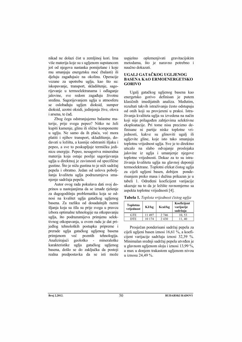
Broj 2,2012. RUDARSKI RADOVI
50
nikad ne dolazi čist u zemljinoj kori. Ima više materija koje su s ugljenom supstancom još od njegova nastanka pomiješane i koje mu smanjuju energetsku moć (balasti) ili djeluju zagađujuće na okolinu. Operacije vezane za upotrebu uglja, kao što su: iskopavanje, transport, skladištenje, sago-rijevanje u termoelektranama i odlaganje jalovine, sve redom zagađuju životnu sredinu. Sagorijevanjem uglja u atmosferu se oslobađaju ugljen dioksid, sumpor dioksid, azotni oksidi, jedinjenja žive, olova i arsena, te čađ.
Zbog čega odstranjujemo balastne ma-terije, prije svega pepeo? Nitko ne želi kupiti kamenje, glinu ili slične komponente u uglju. Ne samo da ih plaća, već mora platiti i njihov transport, skladištenje, do-davati u ložišta, a kasnije odstraniti šljaku i pepeo, a sve to poskupljuje termičku jedi-nicu energije. Pepeo, nesagoriva mineralna materija koja ostaje poslije sagorijevanja uglja u direktnoj je zavisnosti od specifične gustine. Što je niža gustina to je niži sadržaj pepela i obratno. Jedan od uslova pobolj-šanja kvaliteta uglja podrazumjeva sma- njenje sadržaja pepela.
Autor ovog rada pokušava dati svoj do-prinos u nastojanjima da se iznađe rješenje za dugogodišnju problematiku koja se od-nosi na kvalitet uglja gatačkog ugljenog basena. Za razliku od dosadašnjih razmi šljanja koja su išla su prije svega u pravcu izbora optimalne tehnologije na otkopavanju uglja, što podrazumijeva primjenu selek-tivnog otkopavanja, u ovom radu je dat pri-jedlog tehnoloških postupka pripreme i prerade uglja gatačkog ugljenog basena primjenom već pozntih tehnologija. Analizirajući geološko - mineraloške karakteristike uglja gatačkog ugljenog basena, došlo se do zaključka da postoji realna predpostavka da se isti može
uspješno oplemenjivati gravitacijskim metodama, što je naravno potrebno i naučno dokazati.
UGALJ GATAČKOG UGLJENOG BASENA KAO ERMOENERGETSKO GORIVO
Ugalj gatačkog ugljenog basena kao energetsko gorivo definisan je putem klasičnih imedijatnih analiza. Međutim, rezultati takvih istraživanja često odstupaju od onih koji su provjereni u praksi. Istra-živanja kvaliteta uglja su izvedena na način koji nije prilagođen zahtjevima selektivne eksploatacije. Pri tome nisu precizno de-finisane ni partije niske toplotne vri-jednosti, kakve su glinoviti ugalj ili ugljevite gline, koje isto tako smanjuju toplotnu vrijednost uglja. Sve je to direktno uticalo na slabo odvajanje proslojaka jalovine iz uglja i umanjenje njegove toplotne vrijednosti. Dokaz za to su istra-živanja kvaliteta uglja na glavnoj deponiji termoelektrane. Toplotni efekat čistog uglja za cijeli ugljeni basen, dobijen ponde-risanjem preko masa i dužina prikazan je u tabeli 1. Određeni koeficijent varijacije ukazuje na to da je ležište ravnomjerno sa aspekta toplotne vrijednosti [4].
Tabela 1. Toplota vrijednost čistog uglja
Toplotna vrijednost KJ/kg Kcal/kg
Koeficijent varijacije sadržaja
GTE 11 497 2 746 10, 53 DTE 10 174 2 430 11, 40 Prosječan ponderisani sadržaj pepela za
cijeli ugljeni basen iznosi 16,61 %, a koefi-cijent varijacije sadržaja iznosi 32,39 %. Minimalan srednji sadržaj pepela utvrđen je u glavnom ugljenom sloju i iznosi 13,99 %, a max u donjem trakastom ugljenom nivou u iznosu 24,49 %.
Broj 2,2012. RUDARSKI RADOVI
51
Hemijska analiza pepela uglja ukazuje na njegov različit hemijski sastav po ugl-jenim slojevima. Izražene razlike hemi-jskog sastava pepela uglja po slojevima upućuju da ovaj parametar mora biti poštovan pri korišćenju uglja u ter-moenergetske svrhe, načinu odšlja- kivanja, te pri planiranju dinamike ot-kopavanja uglja u cilju obezbjeđenja nje-govog što konstantnijeg hemijskog sastava, da bi se smanjili poremećaji u radu kotlovskog postrojenja.
Veoma značajan kvalitativni poka-zatelj uglja Gatačkog ugljenog basena je njegova meljivost, odnosno lakoća sa ko-jom se može dovoljno fino usitniti, da bi se mogao koristiti kao pulverizirano gorivo. Laboratorijski test meljivosti, preko koga se dolazi do koeficijenta mel-jivosti uglja, od odlučujućeg je značaja pri izgradnji mlinova za usitnjavanje uglja, zatim za pravilno vođenje procesa mljevenja, kao i za ispravno konceptiranje i konstruisanje kotlova za loženje uglje-nim prahom. Dobijeni rezultati ispitivanja meljivosti uglja po metodi Hardgrove ukazuju da je ugalj sva tri ugljena sloja Gatačkog ugljenog basena teško meljiv.
Prioritetni potrošač uglja sa PK „Gračanica” je TE, instalisane snage 300 MW, tako da se kapacitet površinskog kopa i kvalitet otkopanog uglja definiše prema potrebama TE. Ispitivanjem kvaliteta uglja utvrđeno je da se kreće u rasponu od 7.296 do 13.700 KJ/kg, tako da je poznat i mogući raspon kvaliteta otkopanog uglja. Na osnovu podataka isporučioca opreme, za blok snage 300 MW, uključujući i gubitke, specifična potrošnja toplote je 9.837 KJ/KWh, odnosno, potrebna potrošnja uglja za te uslove iznosi 305 t/h. Na godišnjem nivou za fond od 6.000 h rada TE, potreban kapacitet površinskog kopa iznosi 1.830.000 t/god. Pošto je godišnji kapacitet pratećih (mlinskih) postrojenja TE 2.200.000 t/god., minimalna prosječna DTE uglja za taj kapacitet iznosi 8.182 KJ/kg.
Od samog početka rada na PK “Gra-čanica”, prisutan je problem eksploatacije uglja sa velikim učešćem jalovine, što znatno smanjuje snagu kotlovskog postro-jenja TE i povećava količinu pepela koji odlazi u atmosferu i zagađuje čovjekovu okolinu. U zavisnosti od vrste jalovine, smanjenje toplotnog efekta je različito i za 1 % razblaženja iznosi:
• žuti laporac smanjuje toplotni efekat za 122 KJ/kg,
• sivi laporac smanjuje toplotni efekat za 77,98 KJ/kg,
• glinoviti laporac smanjuje toplotni efekat za 67,26 KJ/kg.
Ovo se objašnjava povećanim učešćem karbonatne komponente u određenoj vrsti laporca. Sa porastom karbonata u laporcu, ostvaruje se pad toplotne moći uglja kao goriva. Takozvani žuti laporci, koji najviše utiču na smanjenje toplotne energije, sadrže najviše CaCO3, što se automatski odražava na većem smanjenju toplotne energije po jedinici učešća. Na suprot tome, glinoviti laporci sadrže svega oko 40% CaCO3 i najmanje utiču na smanjenje toplotne energije.
PRIMIJENJENE TEHNOLOGIJE OTKOPAVANJA UGLJA SA LEŽIŠTA GACKO
Osnovni aspekti iskorištavanja posto-jećih rezervi uglja, u cilju dobijanja kvalitet-nog goriva za termoelektranu zahtjevaju vrlo ozbiljan pristup, kako bi se se dobili adek-vatni, maksimalno racionalni tehnološki procesi proizvodnje i sagorjevanja uglja. Imajući u vidu da je ugalj heterogena si-rovina, da se iz istog sloja njegov sastav i osobine mogu razlikovati, postoji potreba da se tehnološkim rješe-njima i postupcima dobijaju što ujednačenije i kvalitetnije karak-teristike.
Iz tih razloga sva problematika vezana za obezbjeđivanje garantovanog kvaliteta uglja kao goriva za TE Gacko, postizanja nominalnog kapaciteta i pouzdanosti rada
Broj 2,2012. RUDARSKI RADOVI
52
kotlovskog postrojenja se usmjerava na iznalaženje tehnoloških rješenja u cilju poboljšanja i ujednačavanja kvaliteta ot-kopanog uglja koji jako varira. Sva dosa-dašnja razmišljanja išla su prije svega u pravcu izbora optimalne tehnologije na otkopavanju uglja, što podrazumijeva prim-jenu selektivnog otkopavanja. Ugalj u ležištu gatačkog basena je složene geološke građe, raslojen znatnim brojem jalovih proslojaka male moćnosti i zbog toga, veoma nezahvalan u pogledu kvaliteta, za eksploataciju i pripremu za potrebe sagor-jevanja u termoelektrani. Primjena rotornog bagera ER-1250 16/1.5, na selektivnom izdvajanju jalovih proslojaka u uslovima gatačkog ugljenog basena je do sada bilo skoro nemoguća, jer se ne dobija ugalj odgovarajućeg kvaliteta.
Primjena rotornog bagera ER-1250 16/1.5, na selektivnom izdvajanju jalovih proslojaka u uslovima gatačkog ležišta je do sada bilo skoro nemoguća, jer se ne dobija ugalj odgovarajućeg kvaliteta. Kod primjene rotornog bagera, veličina reza mora biti najmanje 0,7 prečnika rotora, da bi se postigao optimalni kapacitet. To je uticalo da se odustane od ovog i pristupi traženju novog rešenja.
Primjenu bagera kašikara takođe ograničava nemogućnost selektivnog izdvajanja jalovih proslojaka male moć-nosti, što bitno umanjuje toplotnu vrijed-nost uglja. Sa bagerima kašikarima, jalovi proslojci male debljine se najčešće ot-kopavaju zajedno sa ugljem i transportuju direktno do elektrane.
Primjena otkopne mašine Wirtgen SM 2100 sastoji se u otkopavanju mineralne sirovine u tankim horizontalnim slojevima do 0,20 m, pomoću radnog valjka sa spi-ralno raspoređenim noževima. Iako se, u poređenju sa hidrauličnim bagerima kašikarima, radi o mašini sa velikim mogućnostima u selektivnom radu, ona proizvodi ipak značajne gubitke, jer je praktično nemoguće izdvojiti proslojak jalovine, a da pri tome određene količine
uglja ne budu otkopane s njim. Naravno, javlja se i problem razblaženja jer je nemoguće otkopati ugalj koji zaliježe pod određenim uglom što je čest slučaj u ležišnim uslovima na terenu, a da neke količine jalovine ne budu otkopane sa njim.
Imajući u vidu ovu činjenicu, kao i to:
• da se otkopnim mašinom WIRTGEN ipak daje samo dio proizvodnje uglja (25 %), a ostatak se dobija hidrauličnim bagerima,
• da se ne možemo potpuno osloniti ni na faktor „rukovaoca”, pogotovu pri radu u noćnim smjenama i lošim vremenskim uslovima,
• da se u „čistom” uglju nalaze proslojci i ugljevitog lapora, laporovitog uglja, ugljevite gline, manje toplotne vrijedosti, i proslojci jalovine debljine do 0,2 m koji se selektivno ne odvajaju,
• da je zalijeganje ugljenog sloja pod padnim uglom od 70 – 90,
dolazi se do zaključka da je praktično nemoguće obezbijediti kvalitet „čistog” uglja, već moraju postojati i određena raz-blaženja, zbog primjesa međuslojne ja-lovine koja se otkopava zajedno sa „čistim” ugljem.
U svim ovim slučajevima, kada se ne izvrši kvalitetno odvajanje jalovine ili jalovinskih proslojaka, nastaju između ostalih i dodatni troškovi: otkopavanja i transporta jalovine do elektrane, električne energije koja se troši na mljevenje uglja, vezani za habanje mlinskih postrojenja, prouzrokavani gubitkom toplotne energije na sagorjevanje jalovine, transporta pepela do deponije i deponovanja pepela, a osim toga, često odstupanje karakteristika uglja od garantovanog kvaliteta, ima negativan uticaj na stabilan rad termoelektrane.
Obezbjeđenje karakteristika uglja, u određenim granicama, moguće je ostvariti
Broj 2,2012. RUDARSKI RADOVI
53
postupcima ujednačavanja karakteristika uglja homogenizacijom. Kvalitet postupka homogenizacije, između ostalog zavisi od:
• kvalitetnog dijagnosticiranja kvaliteta uglja u ležištu,
• kontinualnog praćenjem kvaliteta uglja u toku samog procesa proizvodnje,
• tehnologije otkopavanja uglja u ležištu,
• planiranja dinamike otkopavanja, koje se vode u skladu sa dijagno-sticiranim kvalitetom uglja.
I pod uslovom da se svi navedeni zahtjevi ispune, postupkom homogenizacije ipak ne možemo odstraniti jalovinu koja nije ranije izdvojena selektivnim radom na dobijanju uglja. Osim toga, sve podobnosti koje deponija pruža u energetskom kompleksu mogu biti znatno umanjene, ako se ne vodi pravilna tehnologija deponovanja i uzimanja i ako se ne prate promjene u uglju koji je odložen, odnosno spriječi pojava samozapaljenja uglja. Naravno, podra-zumjeva se prije svega, da postoje dovoljne količine otkrivenog uglja različitog kvaliteta, da bi se uopšte moglo pristupiti homo-genizaciji. U situaciji kada zbog zaostatka na otkrivci ne postoje dovoljne količine otkrivenog uglja, različitog kvaliteta, odnosno, kada se zbog „raubovanja“ ležišta na radilištima javlja lošiji ugalj sličnih karakteristika, homogenizacija je nemoguća. Zbog svega navedenog, nameće se pitanje mogućnosti iznalaženje tehnoloških postupaka pripreme i prerade uglja iz gatačkog ležišta u cilju ujednačenja kvaliteta i povećanja toplotne vrijednosti.
TEHNOLOŠKI TIP SIROVINE LEŽIŠTA UGLJA GACKO
Eksploatacija uglja iz ležišta Gacko od 2010. godine vrši se isključivo hidrauličnim bagerima kašikarima, a transport kamionima do deponije drobilice gdje se vrši primarno drobljenje na granulaciju – 300+0 mm.
Ugalj se, potom, transportnim trakama transportuje na sekundarno drobljenje na granulaciju -50+0 mm i na kraju transportnim trakama deponuje na deponiji termoelektrane. Ugalj otkopan mašinom Wirgen, granulacije -50+0 mm se kamionima direktno transportuje na deponiju termoelektrane. Ugalj za potrebe široke potrošnje, otkopan hidrauličnim bagerima kašikarima, direktno se utovara u kamione veće zapremine sanduka ili se transportuje damperima na namjensku deponiju gdje se vrši ručni utovar u kamione manje zapremine sanduka. Ugalj namijenjen kao termoenergetsko gorivo i ugalj namijenjen za potrebe široke potrošnje, isporučuje se krajnjim potrošačima bez dodatnih tehnoloških procesa oplemenjivanja i klasiranja uglja, tako da ugalj iz ležišta Gacko karakteriše jedan tehnološki tip [10].
TEHNOLOŠKI POSTUPCI PRIPREME I PRERADE SIROVINE IZ LEŽIŠTA GACKO
Ugalj otkopan u rudniku uglja „Gacko” se trakastim transporterima doprema do bunkera Glavnog pogonskog objekta termoelektrane (GPO), a zatim u mlinove gdje se melje na određenu granulaciju; potom se ubacuje u ložište kotla gdje sagorijeva. Za proces pripreme uglja, kao namjenskog goriva, vezane su operacije drobljenja i mljevenja, jer se ugalj kao gorivo koristi u vidu praha. Vri-jednost indeksa Hardgrove pokazuje da je ugalj teško meljiv što zahtijeva odgovarajuće mlinove izgrađene od prvoklasnih materijala.
Dobijena toplotna energija zagrijava vodu koja struji kroz cijevni sistem kotla i pretvara se u paru, koja se pregrijava do 545°C i pritiska 24 MPa. Takva para ulazi u turbinu i pokreće rotor turbine brzinom 3.000 o/min, a ujedno i rotor generatora, pa mehaničku energiju pretvara u elek-tričnu. Izlazni napon generatora od
Broj 2,2012. RUDARSKI RADOVI
54
20.000 V transformiše se u napon 400.000 V i takav predaje u sistem. Izlazni gasovi iz kotla prečišćavaju se u elektrofilterima i kroz dimnjak odlaze u atmosferu.
Proizvodnja uglja budućeg PK "Gacko" (kao i sadašnjeg PK "Gračanica") koristiće se za potrebe TE ''Gacko'', za koju je projektovana potrošnja uglja, don-jeg toplotnog efekta 9.100 kJ/kg. Upore-đujući ovu vrijednost sa toplotnom vrijed-nošću ''čistog'' uglja, koja iѕnosi 10.200 kJ/kg, može se konstatovati da će ugalj odgovarati namjeni, uz uslov da se vrši selekcija jalovih proslojaka od 0,2 do 1 m i debljih od 1 m, jer upravo to us-lovljava stepen razblaženja kvaliteta. U periodu 1998-2008. godine, ostvarena je prosječna toplotna vrijednost lignita od oko 8.000 kJ/kg (prema analizama u labo-ratoriji ''Rudnika'' i TE "Gacko").
Usled povećanja procentualnog učešća jalovine u uglju dolazi do povećanja sa-držaja pepela. Sadržaj pepela u uglju varira od sloja do sloja. Najviši je u pov-latnoj ugljenoj zoni (donji trakasti nivo) 24,49%, a najniži u glavnom ugljenom sloju, 13,99%. Prosječan sadržaj pepela u ''čistom'' uglju za cijeli basen je 16,6%. U proračun kvaliteta ''čistog'' uglja uključeni svi oni dijelovi ugljenog sloja koji daje toplotnu energiju veću od 5.000 kJ/kg, (ranije preko 1.200 kcal/kg). Ova vrijed-nost je uzeta kao granica, jer samo ugalj sa manjim DTE, u kombinaciji sa znatno kvalitetnijim dijelovima slojeva u ležištu, daje zadovoljavajuću toplotnu vrijednost.
Upotreba sirovog lignita u komadnom obliku u širokoj i opštoj potrošnji i indus-triji opravdana je samo u okviru ekonom-skog radijusa transporta, jer je njegova top-lotna vrijednost niska. To znači da bi se prodajom prethodno sortiranog sirovog lignita kao goriva u manjim urbanim nasel-jima (bliža okolina rudnika), ostvarili pozitivni ekonomski efekti. Najveći dio proizvedenog sirovog lignita u Republici Srpskoj, međutim, koristi se u TE za proiz-vodnju električne energije.
Problematika vezana za obezbjeđi-vanje garantovanog kvaliteta uglja kao goriva za TE Gacko, postizanja nominal-nog kapaciteta i pouzdanosti rada kot-lovskog postrojenja se usmjerava na iznalaženje tehnoloških rješenja u cilju poboljšanja i ujednačavanja kvaliteta ot-kopanog uglja koji jako varira. Ri-ješavanje problema obezbjeđenja uglja ujednačenog kvaliteta i sastava, može se istraživati u pet elementarnih pravaca:
• primjena selektivne eksploatacije, • homogenizacija uglja na deponiji
termoelektrane, • istraživanje mogućnosti
oplemenjivanja rovnog uglja, • klasiranje uglja, i • termičko iskorištenja uglja.
Oplemenjivanje uglja gravitacijskim metodama
Čišćenje uglja obavlja se u autogenoj suspenziji uz uobičajno korištenje dinamičkog efekta ugrađene opreme. Pod autogenom suspenzijom podrazumjevamo sredinu koja se sama stvara. Ugalj koji treba da se čisti, sam za sebe stvara suspenziju. U svim ugljevima postoje vrlo fine čestice gline, uglja i jalovine, koje predstavljaju vrlo stabilnu suspenziju u vodi. Ova prirodna teška sredina predstavlja ogromnu uštedu u čišćenju uglja pošto nikakva skupa, vještačka suspenzija ne mora da se kupuje, recirkuliše ili regeneriše. Pri određenoj gustini, suspenzija sastavljena od sitnih čestica koje se u prirodnom stanju nalaze u sirovini koja se čisti, postaje suviše viskozna i počinje da gubi određene osobine tečnosti koje su neophodne za proces odvajanja. Gornja granica za gustinu autogene suspenzije maksimalno je 1.25 g/cm3, dok specifična gustina ugljeva iznosi od 1.23 g/cm3, pa naviše. Kod "Parnaby" procesa ovaj nedostatak stvarne gustine nadoknađuje se kombinacijom različitih dinamičkih efekata [7].
Broj 2,2012. RUDARSKI RADOVI
55
Prilikom izbora najpogodnijeg postupka za oplemenjivanje uglja uobičajno je da se u razmatranje tebaju uzeti slijedeći parametri: oštrina odvajanja, visina investicionih ulaganja, rok isporuke opreme, veličina ulazne granulacije, brzina montaže, troškovi čišćenja uglja, instalisana snaga, utrošak vode, broj radnika.
Klasiranje uglja
Jedan dio proizvedenog uglja iz ležišta Gacko (25-30x103 t/god.), isporučuje se za komercijalne potrebe. Već duži vremenski period na površinskom kopu Gacko postoji tehnološki problem isporuke uglja za ko-mercijalne potrebe. Na površinskom kopu nema postrojenja za klasiranje uglja, pa se utovar uglja obavlja direktno hidrauličnim bagerima kašikarima ili ručno na namjen-skoj deponiji. Osim toga, stalno prisustvo kamiona zapremine sanduka od 3-15 m3 u zoni izvođenja rudarskih radova, otežava redovnu proizvodnju i ugrožava bezbjednost rada na površinskom kopu. Rješavanje problema obezbeđenja frakcija uglja za komercijalne potrebe [2], moguće je izgradnjom postrojenja za klasiranje uglja, kapaciteta 250-300 t/h, na najpovoljnijoj lokaciji rudnika tj. pristupnog puta za dampere i kamione, vodeći računa o prilazu utovarnih kamiona na postojeću vagu. Klasiranjem uglja obezbijedile bi se frakcije: komad (-350 do + 100 mm) i kocka (-100 do +30 mm), dok bi se sitni ugalj (-30 mm) transportovao tračnim transporterima na deponiju termo-elektrane. Postrojenje klasirnice uglja je tehnološki nezavisno od postojećeg transporta dopreme uglja sa površinskog kopa u termoelektranu. Zgrada klasirnice ima dva bunkera za komad i kocku kapaciteta 2x150 t/h. Izgradnjom postrojenja za klasiranje uglja omogućilo bi se plansko povećanje količina proizvedenog uglja namijenjenog za komercijalne potrebe u iznosu od 50.000 t/godišnje, a sama tehno-logija pripreme i isporuke uglja za ovu namjenu nema tehnološki uticaj na proiz-vodni proces na površinskom kopu.
Za pojedine frakcije uglja (kocka, orah, sitni) neophodno uraditi skraćenu tehničku analizu (vlaga, pepeo, DTE) jer zhtjevi tržišta i namjena uglja za komerci-jalne potrebe to zahtijevaju. Na osnovu navedenih kvalitativnih karakteristika formira se cijena pojedinih frakcija uglja (KM,€,RSD/MJ).
Bolje termičko iskorištenje uglja iz ležišta Gacko
Najznačajnija fizička svojstva uglja su: optičke osobine, mehaničko-strukturne osobine, specifična gustina, električne osobine, osobine specifične površine [1]. Ugalj proizveden u rudniku Gacko nije naknadno tehnološki oplemenjivan, dok se u Ugljeviku primjenjuje Parnaby tehnologija oplemenjivanja uglja za ko-mercijalne potrebe, čime se postiže bolje termičko iskorišćenje uglja. Da bi se sagledala mogućnost dobijanje goriva boljih kvalitativnih karakteristika neo-phodno je izvršiti ispitivanja uglja iz ležišta Gacko kroz različite tehnološke procese oplemenjivanja uglja (briketi-ranje, gasifikacija, sušenje lignita, likvi-fakcija-tečni proizvod hidrogenizacije) sa ciljem dobijanja produkata uglja veće top-lotne vrijednosti. Pri izboru tehnologije oplemenjivanja mekog mrkog uglja, pot-rebno je prethodno utvrditi njegove fizičke i hemijske karakteristike, kao i izvršiti ispitivanje kvalitativno-kvantitativnom mikro-petrografskom analizom [6].
ZAKLJUČAK
Imajući u vidu da je ugalj heterogena sirovina, da se iz istog sloja njegov sastav i osobine mogu razlikovati, postoji potreba za tehnološkim postupcima pripreme i prerade u cilju dobijaju što kvalitetnijeg goriva za potrebe termoelektrane Gacko i komerci-jalnu potrošnju. Uvođenjem ovih rješenja stiču se uslovi za vođenje procesa sagori-jevanja uglja sa što manje oscilacija. Pri sagorijevanju ugljenog praha u kotlovima
Broj 2,2012. RUDARSKI RADOVI
56
mogu se očekivati neželjene i neočekivane posljedice. U principu, kotlovi su pro-jektovani da zadovolje garantovane karak-teristike za određeni ugalj, i u tom slučaju da termoelektrana radi sa maksimalnom efikasnošću. Uobičajeno je da postoji dopušteni opseg promjena najvažnijih karakteristika uglja sa kojima se očekuje ostvarivanje maksimalnog opterećenja.
Tehnološkim postupcima pripreme i prerade uglja sa ležišta Gacko, bili bi tretirani samo oni dijelovi ugljenog sloja koji postojećim sistemom eksploatacije ne mogu obezbijediti gorivo za termoe-lektranu garantovane toplotne vrijednosti.
Uvođenje tehnoloških postupaka oplemenjivanja uglja gravitacijskim metodama valorizovala bi se cjelokupna količina uglja na ležištu Gacko. Kla-siranjem i oplemenivanjem uglja kao i primjenom metoda boljeg termičkog iskorištenja uglja dobio bi se tržišni proizvod namijenjen za komercijalnu potrošnju, konkurentan u regionu.
LITERATURA
[1] Bugarin M, Geologija ugljeva, Institut za bakar, Bor, 2006, str. 9-10.
[2] Mujezinović I., Begić A., Bijedić N., Đulović K., Moranjkić I., Pirić E., Kurtić N., Mulahasanović F, Glavni rudarski projekat klasiranja uglja na PK „Gračanica” Gacko, Rudarski institut d.d., Tuzla, 2010, str. 1-4.
[3] Janković S., Milovanović D, Eko-nomska geologija i osnovi ekonomike mineralnih sirovina, Beograd, 1985, str. 66-76.
[4] Olujić J., Glavaš S., Nikolić D, Elaborat o klasifikaciji, kategorizaciji i proračunu rezervi uglja u ležištu Gacko sa stanjem 31.12.2006. g, Geozavod – Zvornik, 2007, str. 10 – 48.
[5] Projekat, Dopunski rudarski projekat površinskog kopa Gračanica - Gacko do kraja eksploatacije, Centar za površinsku eksploataciju, Beograd, 2005.
[6] Stojanović R., Vuković B, Primjena hidrauličnih bagera kašikara na selektivnoj eksploataciji uglja na PK „Gračanica“ Gacko,-Zbornik radova, Rudarstvo 2011, Vrnjačka Banja, 2011, str. 353-362
[7] Vuković B., Petrović M., Petrović P., Bijelić V., Stanimirović B, Mogućnost poboljšanja kvaliteta uglja sa PK „Gračanica” Gacko uvođenjem paranaby tehnologije, Naučno-stručni skup “Savremena dostignuća u istraživanju, eksploataciji i korišćenju mineralnih sirovina u Republici Srpskoj”, Gacko, 2004, str. 96-111.
[8] Vuković B, Uticaj međuslojne jalovine na toplotni efekat čistog uglja kao energetskog goriva za potrebe termoelektrane Gacko, - Zbornik radova, II savjetovanje geologa BiH, Teslić, 2006, str. 213.
[9] Vuković B, Geološko-ekonomska ocena neobnovljivih energetskih resursa Republike Srpske u funkciji nacionalne i komercijalne isplativosti, doktorska disertacija, RGF, Beograd, 2011, str. 127-129.
No 2, 2012. MINING ENGINEERING
57
MINING AND METALLURGY INSTITUTE BOR YU ISSN: 1451-0162 COMMITTEE OF UNDERGROUND EXPLOITATION OF THE MINERAL DEPOSITS UDK: 622
UDK: 622.33:662.642.2:621.311.24 (045)=20
Boško Vuković*, Vesna Ljubojev**
TECHNOLOGICAL PROCESSES OF INCREASING THE EFFICIENCY OF CALORIFIC VALUE OF COAL AS THE
ENERGY RESOURCE OF THE GACKO DEPOSIT
Abstract
This paper describes the conceptual technological processes of coal preparation and process-ing from the deposit Gacko (Republic Srpska) to the aim of increasing the efficiency of calorific value of fuel for the needs of Thermal Power Plant Gacko.The excavated coal from the coal de-posit Gacko is supplied as the energy fuel for the needs od Thermal Power Plant Gacko as well as for commercial consumption. From total output of coal from from the open pit, which annually amounts on average to 2.2 Mt, and 97% is supplied for the needs of Thermal Power Plant Gacko and 3% forcommercial consumption. During previous mining (1983-2012), some deviations were recorded regarded to the results of calorific value of coal, obtained by detailed geological explo-rations and the results obtained from laboratory analyses on dosers in the Thermal Power Plant Gacko The average calorific value of coal in the deposit Gacko, obtained by geological explora-tions is 10.2 MJ/kg.
The coal deposit Gacko has a complex geological structure and the carbon layers are stratified by substantial numbers of interbeds, thickness of 0.2 to 0.5 m. The selective mining is used for excavation the interbeds of interlayer waste, thickness greater than 0.2 m, and all minor interbeds are mined together with the coal. This technological solution of selective mining does not achieve the optimum economic effects of utilization the carbon material from deposit. The energy fuel of caloricif value from 8 to 8.5 MJ/kg is supplied for the needs of Thermal Power Plant Gacko and and it is lower than the designed parameters for the boiler plant in the Thermal Power Plant Gacko (9.2 MJ kg). Technological methods of coal upgrading and classification would increase the calorific value of coal in relation to the mining conditions.
Keywords: coal, calorificvalue, layer structure, technology type, coal processing, upgrading, classification
* Mine and Thermal Power Plant Gacko, Industrijska zona bb.,
e-mail: [email protected] ** Mining and Metallurgy Institute Bor, 35 Zeleni bulevar, 19210 Bor
INTRODUCTION
Coal is a very complex mixture of minerals and macerals, formed under the influence of very unequal natural proc-
esses. Nature has mixed and blended these two elements in the prehistoric times, many millions of years ago. Coal, with
No 2, 2012. MINING ENGINEERING
58
reserves greater than all other reserves of fossil fuels, is one of the largest sources of energy in the world. Most of the coal in the world has the use value primarily as the energy source. In addition, the degree of carbonification increases with the en-ergy value of coal, reduced to the unit mass. But, coal almost never comes clean in the earth crust. There are several sub-stances, mixed with the coal substance since its formation and that it reduce its energy power (ballasts) or pollute the en-vironment. Operations related to the use of coal, such as mining, transport, storage, combustion in the power plants and dis-posal of waste, all of them, pollute the environment. Coal combustion releases into the atmosphere carbon dioxide, sulfur dioxide, nitrogen oxides, compounds of mercury, lead and arsenic, and soot.
Why the ballast substances, primarily ash, are removed? Nobody wants to buy the stones, clay or similar components in coal. Not only to pay for them, their trans-port and storage have to be paid and later to add them into the fireboxes, and later to remove the slag and ash, and all that raise in price the thermal unit of energy. Ash, the incombustible mineral matter, re-mained after coal combustion, is directly depending on density. Lower the density, lower the ash content and vice versa. One of the conditions to improve the coal qual-ity involves the reduction of ash content.
The author of this paper tries to con-tribute in the efforts to find a solution to longstanding problems related to the coal quality of the Gacko Coal Basin. In con-trast to previous thinking that went pri-marily towards a choice of optimum technology in coal mining, which involves the use of selective mining, this paper presents a proposal of technological pro-cedures of preparation and processing of coal in the Gacko Coal Basin using the already known technologies.
Analyzing the geological-minera-logical characteristics of coal from the Gacko Coal Basin, it was concluded that
there is a supposition that it can be success-fully refined using the gravity methods, whichhas to be scientifically proven.
COAL FROM THE GACKO COAL BASIN AS A THERMAL ENERGY FUEL
Coal from the Gacko Coal Basin as an energy fuel is defined by the classical im-mediate analyses. However, the results of such studies often differ from those tested in practice. Investigations of the coal qual-ity were carried out in a way that is not modified to the requirements of selective exploitation. In doing so, the parties of low calorific value were not precisely de-fined, such as clay coal or carbonaceous clay, which also reduce the calorific value of coal. All of this has directly affected the poor separation of waste interlayers from coal and reduction of its calorific value. The investigations of coal quality are the proof of this on the main landfill of the Power Plant. Thermal effect of clean coal for the entire coal basin, obtained by weighting the masses and lengths is shown in Table 1. The certain coefficient of variation indicates that the deposit is uniform in terms of calorific value [4].
Table 1. Calorific value of pure coal
Calorific value KJ/kg Kcal/kg
Coefficient of content variation
GTE 11 497 2 746 10.53
DTE 10 174 2 430 11.40
The average weighted ash content for the entire coal basin is 16.61%, and coef-ficient of content variation is 32.39%. Minimum average ash content was deter-mined in the main coal seam and it is 13.99%, and maximum in the lower band level of coal in the amount of 24.49%.
Chemical analysis of coal ash shows its different chemical composition per coal seams. The marked differences of chemical composition of coal ash in seams indi-
No 2, 2012. MINING ENGINEERING
59
cate that this parameter has be respected in the use of coal for thermal power pur-poses, the way deslaging and planning the dynamics of coal mining in order to en-sure it as much as possible constat chemi-cal composition, to reduce disorders in a boiler operation.
Very important indicator of coal qual-ity in the Gacko Coal Basin is its grindability, and ease with which it can be finely comminuted, as it could be used as a pulverized fuel. Laboratory test of grindability, through which the grindabil-ity coefficient of coal is obtained, is of decisive importance in construction of mills for coal comminution, then the proper running of the grinding process, and proper conception and construction of boilers for firing with pulverized coal powder. The obtained testing results of coal grindability by the Hardgrove method have indicated that all three coal seams of the Gacko Coal basin are hard grindable.
Priority consumer of coal from the Open Pit “Gračanica” is the Thermal Power Plant, 300 MW of installed capac-ity, so that the capacity and open pit and quality of excavated coal are defined ac-cording to the needs of Thermal Power Plant. Testing the coal quality has found that it ranges from 7,296 to 13,700 KJ/kg, so the possible range of excavated coal quality is well known. Based on the data equipment supplier, for a block of 300 MW, including losses, the specific heat consumption is 9837 kJ/kWh, respec-tively, the required consumption of coal for these conditions is 305 t/h. On the an-nual basis for fund of 6,000 h operation of the Thermal Power Plant, the required capacity of open pit is 1,830,000 t/year. Since the annual capacity of supporting (mill) plants of the Thermal Power Plant is 2.2 million t/y, minimum average DTE of coal for this capacity is 8,182 KJ/kg.
From the beginning of operation at the Open Pit “Gračanica” there is a problem of coal mining with a high share of waste
which significantly reduces the power of boiler plant of the Thermal Power Plant and increases the amount of ash into the atmosphere and polluting the human envi-ronment. Depending on the type of waste, reduction of the thermal effect is different and for 1% dilution is:
• yellow marl reduces the thermal effect for 122 KJ/kg,
• gray marl reduces the thermal effect for 77.98 KJ/kg,
• clay marl reduces the thermal effect for 67.26 KJ/kg.
This is explained by the increased par-ticipation of carbonate components in a particular type of marl. With the increase of carbonate in marl, a decline in calorific power coal as fuel is realized. The so-called yellow marl, which mostly reduces the calorific power, contains the highest CaCO3, which is automatically reflected in higher reduction in thermal energy per unit of share. In contrast, clay marl con-tains only about 40% CaCO3 and at least reduce the calorific power.
THE APPLIED TECHNOLOGIES OF COAL MINING FROM THE GACKO DEPOSIT
The basic aspects of utilization the ex-isting coal reserves, in order to obtain high-quality fuels for the Thermal Power Plant require very serious approach, in order to obtain adequate, maximum rational techno-logical processes of production and com-bustion of coal. Having in mind that coal is a heterogeneous material, and that its com-position and properties can varyfrom the same seam, there is a need to get smoother and better characteristics using the techno-logical solutions and procedures.
Due to these reasons, all problems re-lated to providing the guaranteed quality of coal as a fuel in TPP Gacko, achieving the rated capacity and reliability of the boiler plant operation is focused on find-ing the technological solutions to improve and standardize the quality of mined coal
No 2, 2012. MINING ENGINEERING
60
that varies very much. All previous thinking went so far primarily towards the choice of optimum technology of coal mining, which involves the use of selective mining. Coal in the deposit of Gacko Basin is of a complex geological structure, stratified by substantial numbers of dirt bands of small thicknrss and therefore it is ungrateful in terms of quality for exploitation and preparation and exploi-tation for the needs of combustion in the power plant. The use of bucket wheel exca-vator ER-1250 16/1.5 for selective separa-tion of dirt bands in the conditions of the Gacko Coal Basin was almost impossible until now, because the suitable quality of coal was not obtained. In the use of bucket wheel excavator, the size of cut must be at least 0.7 of rotor diameter to achieve the optimum capacity. It has an influence to withdraw this and to find out a new solution.
The use of shovel excavator also limits the impossibility of selective extraction of dirt bands moćnosti small, which signifi-cantly reduces the calorific value of coal. With shovel excavators, thin waste inter-beds are usually excavated with coal and transported directly to the Power Plant.
The use of excavation machine Wirt-gen 2100 SM consists in mining the min-eral resources in thin horizontal seams up to 0.20 m, with the working cylinder with spirally arranged knives. Although, com-pared with hydraulic shovels, it is a ma-chine with a large range in selective work; it still produces significant losses because it is practically impossible to separate a dirt band of waste without having the cer-tain amount of coal which cannot be exca-vated with it. Of course, there is a problem of dilution because it is impossible to ex-cavate coal at certain angle, what is often a case in the conditions of deposit on the ground, and that some amount of waste would not been excavated with it.
Having in mind this fact, as well as that:
• the excavation machine WIRTGEN still provides only a portion of coal production (25%), and the rest is obtained by hydraulic excavators,
• it could not be completely relied on a factor of "operator", especially dur-ing work in night shifts and poor weather conditions,
• in the "clean" coal ther are the inter-beds of carbonaceous marl, marl coal, carbonaceous clay, of lower calorific value and interbeds of waste, thickness to 0.2 m, which are not selectively separated,
• the coal seams fall under an angle of 70 – 90,
it can be concluded that it is practically impossible to provide the quality of "clean" coal, but there must be some dilu-tion due to the additions in interbed waste that is excavated with the "clean" coal.
In all these cases when there is no suit-able separation of waste or waste inter-beds, there are the additional costs of: excavation and transport of waste to the Power Plant, electrical energy used for coal grinding, related to the wear of mill-ing facilities, caused by the loss of heat energy for waste burning, ash transport disposal to the landfill, and beside this, and ash disposal, often deviation of the coal characteristics from the guaranteed coal quality, what has a negative effect on stable operation of the Power Plant.
Providing the characteristics of coal, within the certain limits, is possible to achieve by the equalization procedures of coal characteristics by homogenization. The quality of the homogenization proce-dure, among other things, depends on:
• diagnostic quality of coal quality in the deposit,
• continuous monitoring of coal qual-ity during the production process,
No 2, 2012. MINING ENGINEERING
61
• technology of coal mining in the de-posit,
• planning the dynamics of mining, managed under the diagnosed coal quality.
And under the conditions that all the above requirements are met, the homogeni-zation procedure cannot remove the waste which was not previously extracted by se-lective operation of coal obtaining. In addi-tion, all suitabilities provided by the landfill in the energy complex can be significantly reduced if the technology fails to keep proper and deposit taking and if the changes are not followed in coal, which is delayed, or prevent the occurrence of spon-taneous combustion of coal. Of course, it implies, first of all, there is a sufficient quantity of discovered coal of different quality, to be able to access the homogeni-zation. In a situation when there are no sufficient quantities of discovered coal of different quality, i.e. due to utilization of deposit, low quality coal of similar deposit occurs at sites with similar characteristics, the homogenization is impossible. Because of this, there is a question on a possibility of finding out the technological methods of preparation and processing of coal from the Gacko coal deposit for balance of quality and increase the calorific value.
TECHNOLOGICAL TYPE OF MIN-ERAL RESOURCE AT THE GACKO COAL DEPOSIT
Coal mining in the Gacko deposit since 2010 has been exclusively done by hydrau-lic shovels and dump trucks for transport to the crusher where the primary crushing is done to the grain size of - 300 +0 mm. Coal is then transported by belt conveyors to the secondary crushing to the grain size of -50 +0 mm and, at the end, by belt conveyor is deposited in the landfill of the Power Plant. Coal excavated by Wirgen machine, grain size -50 +0 mm is directly transported by trucks to the landfill of the Power Plant. Coal for the consumer needs,
excavated by hydraulic shovels, is directly loaded into trucks with larger volume boxes or transported to a dedicated landfill by dump trucks where it is manually loaded into trucks with small volume boxes. Coal, intended as the thermal energy fuel and coal for the needs of consumers are deliv-ered to the end users without additional technological processes of coal refining and classification, such as the coal from the Gacko deposit is characterized by one technological type [10].
TECHNOLOGICAL METHODS OF PREPARATION AND PROCESSING THE MINERAL RESOURCE FROM THE GACKO DEPOSIT
The excavated coal in the mine "Gacko" is delivered by belt conveyors to the bins of the Main drive facility of the Power Plant (MDF), and then into the mills where it is ground to the certain grain size, then injected into the combus-tion chamber of boiler where it burns. For the process of coal preparation, as the purposed fuel, the operations of crushing and grinding are connected, because coal is used as fuel in the form of powder. Value of the Hardgroove index shows that coal is difficult grindable, what requires the appropriate mills constructed of first-class materials.
The resulting heat warms the water that flows through the pipe system of the boiler and turns into steam, which heats up to 545°C and pressure of 24 MPa. This steam enters the turbine and drives the turbine rotor in speed 3000 rpm, and also the rotor of generator and converts the mechanical energy into electrical energy. Generator output voltage of 20,000 V is transformed into voltage V 400,000, and as such is taught into system. Output gases from the boiler are purified in electric fil-ters and leave through the chimney into the atmosphere.
Coal production of the future Open Pit "Gacko" (as well as the current Open Pit
No 2, 2012. MINING ENGINEERING
62
"Gračanica") will be used for the needs of “TPP Gacko”, with designed coal con-sumption of lower calorific effect of 9,100 kJ/kg. Comparing this value with the thermal value of ''clean'' coal, which amounts to 10 200 kJ / kg, it can be con-cluded that coal will be suitable for the purpose, providing that the selection is made of dirt bands from 0.2 to 1 m and thicker than 1 m, because the degree of quality dilution is conditioned by selec-tion. In the period 1998-2008, the average lignite calorific value was achieved of about 8000 kJ/kg (according to the analy-ses in the laboratory of the ''Mine and TPP Gacko").
Due to the increased percentage of waste in coal, the increased content of ash occurs. Ash content in coal varies from seam to seam. The highest is in the imme-diate coal zone (lower band level) 24.49%, and the lowest in the main coal seam, 13.99%. The average ash content of the ''clean'' coal for the entire basin is 16.6%. Calculation the quality of “pure'” coal includes all those parts of coal seam, which provides thermal energy higher than 5,000 kJ / kg, (earlier over 1,200 kcal/kg). This value is taken as the limit, because only coal with lower DTE, com-bined with more qualitative parts of seams in the deposit, providest the sufficient calorific value.
The use of raw coal in a piece shape in broad and general consumption and indus-try is justified only within the economic radius of transport, due to its low calorific value. This means that the sale of pre-sorted raw lignite as a fuel in small urban areas (closer to the mine environment), would achieve the positive economic ef-fects. Most of the produce raw coal in the Republic Srpska, however, is used in the thermal power plants for the production of electricity.
The problems related to supply the guaranteed quality of coal as a fuel for
TPP Gacko, achieving the rated capacity and reliability of operation the boiler plant, is focused on finding out the tech-nological solutions to improve and stan-dardize the quality of excavated coal that varies greatly. Solving the problem of supplying the coal of uniform quality and composition, can be studied in five basic directions:
• application of selective exploitation; • homogenization of coal at the landfill
of power plant; • investigation the possibility of val-
orization the run-of-mine coal, • classification of coal, and • thermal efficiency of coal.
Coal valorization using the gravity methods
Coal cleaning is carried out in autoge-nous suspension with usual use of dy-namic effect of installed equipment. The autogenous suspension means a self-created medium. Coal to be cleaned, itself creates a suspension. In all coals, there are very fine particles of clay, coal and waste, which are very stable suspension in water. This natural hard environment is an enor-mous saving in coal cleaning because no expensive, artificial suspension have to be purchased, recycled or regenerated. At the certain density, suspension composed of fine particles, which in the natural state are present in the raw material to be cleaned, becomes too viscous and begins to lose some fluid properties, required for the separation process. The upper limit for density of autogenous suspension is maximum of 1.25 g/cm3, while specific mass of coal 1.23 g/cm3, and more. In the "Parnaby" process, this lack of real den-sity is compensated by combining the various dynamic effects [7].
In selection the most appropriate proce-dure for coal valorization, it is common to take into consideration the following pa-rameters: sharpness of separation, amount of
No 2, 2012. MINING ENGINEERING
63
investments, term of equipment delivery, size of the input grain size, rate of installa-tion, cost of coal cleaning, installed capacity, water consumption, number of employees.
Coal classification
A part of produced coal from the de-posit Gacko (25-30x103 t/year) is supplied for commercial purposes. For a long time, in the Open Pit Gacko, there is a techno-logical problem of coal delivery for com-mercial needs. The Open Pit does not have facilities for coal classification, so coal loading is direct by hydraulic shovels, or manually at a dedicated landfill. In addi-tion, constant presence of trucks with box volume of 3-15 m3 in the area of mining works makes difficult the regular produc-tion and threats the safety of works at the open pit. Solving the problem of supply-ing the coal fractions for commercial pur-poses [2], it is possible to build a plant for coal classification, capacity 250-300 t/h at the most suitable location of the mine, i.e. the access road for dump trucks and trucks, taking into account the entrance of loading trucks at the existing scale. Classi-fication of coal would provide the follow-ing fractions: a piece (-350 to + 100 mm) and a cube (-100 to +30 mm), while the fine coal (-30 mm) would be transported by belt conveyors to the landfill of power plant. Coal classification plant is techno-logically independent of the existing transport of coal delivery from the open pit into power plant.
The building of classification plant has two bins for a piece and cube, capacity of 2x150 t/h. The construction of facilities for coal classification would allow the planned increase in the quantities of pro-duced coal, intended for commercial pur-poses in the amount of 50,000 t/year, and the technology itself of preparation and delivery of coal for this purpose has no a technological impact not impact on tech-nological process at the open pit.
For each coal fractions (cube, nut, fine), it is necessary to carry out a short-
ened technical analysis (moisture, ash, DTE), because the market needs and uses of coal for commercial purposes require it. Based on these qualitative characteristics, the price of certain fractions is formed (KM, €, RSD/MJ).
Better thermal utilization of coal from the Gacko deposit
The most important physical properties of coal are: optical properties, mechanical-structural properties, specific density, elec-trical properties, and the properties of spe-cific surface area [1]. The produced coal in the mine Gacko was not subsequently tech-nologically valorized technology, while the Parnaby technology of coal valorization is used in Ugljevik for commercial purposes, resulting in better thermal utilization of coal. In order to consider the possibility of obtaining the fuels with better quality char-acteristics, it is necessary to carry out test-ing of coal from the depositGacko through various technological processes of coal valorization (briquetting, gasification, coal drying, liquefaction-liquid product of hy-drogenation) in order to obtain the coal products of higher calorific value. In selec-tion of valorization technology of soft brown coal, it is firstly necessary to deter-mine its physical and chemical properties, as well as carrying out testing by qualita-tive and quantitative micro-petrographic analysis [6].
CONCLUSION
Having in mind that coal is a hetero-geneous mineral resources, the composi-tion and properties can vary from the same seam, there is a need for technological processes of preparation and processing in order to obtain as much as possible quality fuel for the needs of Thermal Power Plant Gacko and commercial consumption. By introduction of these solutions, the condi-tions are acquired for leading the process of coal combustion with as less as possible
No 2, 2012. MINING ENGINEERING
64
oscillations. During burning the coal powder in the boilers, the unintended and unwanted side effects can be expected. In principle, the boilers are designed to meet the guaranteed characteristics for the certain coal, and in this case the power plant is at maximum efficiency. Normally, there is a permissible range of the most important changes in coal characteristics which are expected to realize maximum loads.
Technological methods of coal prepara-tion and processing from the deposit Gacko, only those parts of the coal seam would be treated that cannot provide fuel for the Thermal Power Plant of guaranteed values by the existing system of exploitation.
The introduction of technological methods of coal valorization using the gravity methods would valorise total quantity of coal in the Gacko deposit. Coal classification and valorization as well as the use of methods with better thermal efficiency of coal would produce a market product intended for commercial consumption, competitive in the region.
REFERENCES
[1] Bugarin M, Geology of Coal, Copper Institute, Bor, 2006, pp. 9-10 (in Serbian)
[2] Mujezinović I., Begić A., Bijedić N., Đulović K., Moranjkić I., Pirić E., Kurtić N., Mulahasanović F., The Main Mining Design of Coal Classification at the Open Pit “Gračanica” Gacko, Mining Institute Ltd., Tuzla, 2010, pp. 1-4 (in Serbian);
[3] Janković S., Milovanović D., Economic Geology and Basis of Economics of Mineral Resources, Belgrade, 1985, pp. 66-76 (in Serbian);
[4] Olujić J., Glavaš S., Nikolić D., Study on Classification, Cathegorization and Calculation the Ore Reserves in the Deposit Gacko as of 31.12.2006, Geozavod – Zvornik, 2007, pp.10-48 (in Serbian);
[5] Design, The Additional Mining Design of the Open Pit Gračanica - Gacko by the end of Mining, Centre for Open Pit Mining, Belgrade, 2005 (in Serbian);
[6] Stojanović R., Vuković B., The Use of Hydraulic Shovel Excavators on the Selective Coal Mining at the Open Pit “Gračanica“ Gacko, Proceedings, Mining 2011, Vrnjačka Banja, 2011,pp.353-362 (in Serbian);
[7] Vuković B., Petrović M., Petrović P., Bijelić V., Stanimirović B., Possibility of Coal Improvement from the Open Pit “Gračanica“ Gacko by Introduction the Paranaby Technology, Scientific Conference "Modern Achievements in Exloration, Exploitation and Use the Mineral Resources in the Republic Srpska", Gacko, 2004, pp.96-111 (in Serbian);
[8] Vuković B., The Influence of Interlayered Waste on Thermal Effect of Pure Coal as the Energy Fuel for the Needs of Thermal Power Plant Gacko, Proceedings, II Conference of the B&H Geologists BiH, Teslić, 2006, p.213 (in Serbian);
[9] Vuković B., Geological – Economic Evaluation of Non-renewable Resources of the Republic Srpska as a Function of National and Commercial Profitability, Ph.D.Thesis, Faculty of Mining and Geology, 2011, pp.127-129 (in Serbian).
Broj 2,2012. RUDARSKI RADOVI
65
INSTITUT ZA RUDARSTVO I METALURGIJU BOR YU ISSN: 1451-0162 KOMITET ZA PODZEMNU EKSPLOATACIJU MINERALNIH SIROVINA UDK: 622
UDK: 622.332:622.261.2(045)=861
Dragomir Bukumirović*, Mensud Turković*, Zdravko Zarić*
STRUKTURNO ISPITIVANjE SLOJEVA U JAMI RMU „ŠTAVALj“
Izvod
Na osnovu sprovedenih istraživanja i iskustva stečenih dosadašnjim radovima eksploatacije uglja u Sjeničkom basenu neosporno je da se kapacitet proizvodnje može značajno uvećati uz prethodno rešavanje pitanja izgradnje termoenergetskog objekta. Rezerve uglja i relativno pov-o-ljni prirodno-geološki uslovi koji dopuštaju primenu visokoproduktivnih mehanizovanih tehnoloških rešenja, što ovom rudniku daje niz komparativnih prednosti u odnosu na ostale rud-nike uglja u Srbiji.
Ključne reči: podzemna eksploatacija, jamske prostorije, indirektno merenje, prirodni padni ugao
* JP PEU Resavica, Rudnik „Štavalj“-Sjenica * JP PEU Resavica, Rudnik Mrkog uglja „Rembas“
1. UVOD
Podzemne prostorije predstavljaju, izvan-redne i kontinuirane izdanke, često mnogo kilometara duge, ali tako lokalizovane da omogućavaju upoznavanje i ispitivanje ležišta samo po strogo određenim i ogra-ničenim putevima. Slika o geologiji ležišta koju tokom kartiranja stvori geolog ne predstavlja samo neobaveznu geološku pretpostavku o sastavu i strukturi jednog određenog terena, nego prikaz od kojeg zavise često veoma obimne i skupe investicije i koji će već prvi dalji istražni radovi podvrgnuti strogoj kontroli i proveriti u pogledu ispravnosti pretpostavki i rešenja.
Osnovni zadatakrudara - geologa u rud-niku predstavlja stalno praćenje i rešavanje geologije ležišta putem kartiranja jamskih prostorija. Ovo je veoma odgovoran posao koji traži brižljivu pripremu i precizno
izvođenje, uz korišćenje svih geoloških metoda koje mogu pomoći pri rešavanju brojnih pitanja ležišta – strukturnih i genetskih, teoretskih i praktičnih, vezanih za rešavanje odnosa masa u ležištu, važnih za dalje istraživanje i eksploataciju. Sveže izgrađene jamske prostorije daju najviše informacija, pa se stoga snimanje izvodi paralelno sa napredovanjem jamskih radova.
Pored geološke građe i istorije terena kar-tiranje jamskih prostorija treba da pruži po-datke praktičnog značaja o mineralnim sirovi-nama, a zatim o inženjersko-geološkim, hidro-geološkim i geomorfološkim osobinama leži-šta. Od svih ovih ispitivanja najvažnija su ona koja su vezana za mineralne sirovine; ostala se najčešće svode na notiranje određenih pojava i osobina, osim ako su tereni izuzetno zanimljivi sa gledišta neke od ovih disciplina.
Broj 2,2012. RUDARSKI RADOVI
66
Kartiranjem jamskih prostorija dobijaju se precizni podaci o tipovima slojevitosti, planara i lineara koji su u ležištu razvijeni. Jamske prostorije predstavljaju ključne izdanke čije pravilno kartiranje daje prave i tačne podatke za tumačenje osmatranih podataka a time i ispravno projektovanje i izvođenje podzemnih prostorija.
2. DEFINISANJE PROSTORNE ORIJENTACIJE LINEARA I PLANARA
Prostornu orijentaciju lineara i planara pokazuju njihovi elementi pada – azimut pada i padni ugao.
Geometrijsko mesto tačaka sa istom kotom na jednoj geološkoj ravni zove se pružanje; normalno na pružanje u merenoj ravni stoji padna prava ravni. Njeni elementi pada ujedno određuju i elemente pada ravni.
Azimut pada (ν) je horizontalni ugao koji zaklapa geološka lineara ili padna pra-va geološke planare sa meridijanom mesta, meren od meridijana mesta u smeru kaza-ljke na satu. Može imati vrednost 0-360 º.
Padni ugao (α) je vertikalan između horizontalne ravni i geološke lineare, odnosno padne prave geološke planare. Vrednosti mu iznose 0-90o .
Elementi pada se ispisuju: azimut pada/padni ugao (na primer 234/47).
3. TAČNOST MERENJA ELEMENATA PADA
Više faktora utiče na tačnost merenja elemenata pada. To su pre svega subjek-tivni psihološki faktori, reprezentativnost merene površi, ispravnost kompasa, pri-sustvo magnetske anomalije.
Uslovi merenja su često nepogodni u jami (atmosferski uslovi: vlaga, prašina, nedostatak kisonika, osvetljenost, pri-sustvo metala, zagušljivost, zamor i dr.). Sa druge strane neki kompasi imaju obeležene samo uglove od po 5º na skali, pa na ove greške treba obratiti pažnju.
Reprezentativnost merene površi je od najvećeg značaja. Geološke planare mogu
imati neravne površi zbog načina kako su fizički izražene, čak iako su same u celini posmatrano idealne geometrijske ravni. Čak i statističko merenje desetina eleme-nata pada može dati sumnjive rezultate.
Zato smo u praksi rudnika »Štavalj« poznavajući globalno strukturu i tektoniku celokupnog ležišta i njegovih pojedinih delo-va pribegao drugim metodama indirektnog merenja elemenata pada u dekametarskom i hektometarskom mernom području i dobio rezultate koji u praktičnom smislu nepogre-šivo usmeravaju rudarske radove.
4. INDIREKTNO MERENJE ELEMENATA PADA METODOM »TRI TAČKE«
Kod geoloških karata, situacionih planova jame ili kod dubinskog bušenja, gde se mogu dobiti tri tačke koje leže u sloju a poznate su im planimetrijske koordinate i kote može se primeniti metod indirektnog merenja elemenata pada sloja. Ako planara između njih nije raskinuta i dislokovana rasedom, ili jače u većim razmerama ubrana, te tri tačke definišu ravan sloja i pomoću njih se mogu odrediti njegovi elementi pada.
Rešenje se dobija nalaženjem hori-zontalne prave u ovoj ravni, koja tada pokazuje pružanje, i obaranje padne prave u horizontalnicu radi određivanja padnog ugla. Tehnički se problem može rešiti na više načina, koji se svode na razne varijante realizacijom istog osnovnog postupka.
Primer 1. Na situacionom plan jame »Štavalj«
razmere 1: 1000 u jugozapadnom delu bloka 8 definisane su tri geodetske tačke izvedenih rudarskih radova, sa poznatim koordinatama i kotom podine ugljenog sloja. Metodom nacrtne geometrije treba odrediti elemente pada ugljenog sloja.
Tri tačke koje leže u sloju su: A: X=4 792 560; Y=7 429 898; Z= 945,31 B: X= 4 792 580; Y= 7 430 022; Z= 902,73 C: X= 4 792 626; Y= 7 429 926; Z= 881,42
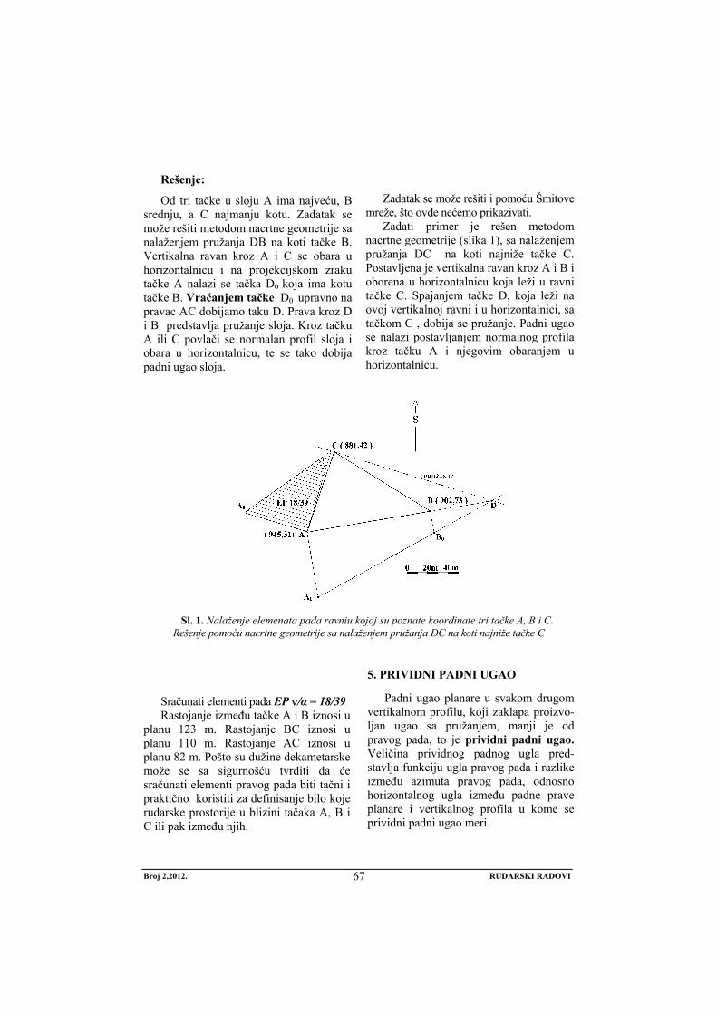
Broj 2,2012. RUDARSKI RADOVI
67
Rešenje:
Od tri tačke u sloju A ima najveću, B srednju, a C najmanju kotu. Zadatak se može rešiti metodom nacrtne geometrije sa nalaženjem pružanja DB na koti tačke B. Vertikalna ravan kroz A i C se obara u horizontalnicu i na projekcijskom zraku tačke A nalazi se tačka D0 koja ima kotu tačke B. Vraćanjem tačke D0 upravno na pravac AC dobijamo taku D. Prava kroz D i B predstavlja pružanje sloja. Kroz tačku A ili C povlači se normalan profil sloja i obara u horizontalnicu, te se tako dobija padni ugao sloja.
Zadatak se može rešiti i pomoću Šmitove
mreže, što ovde nećemo prikazivati. Zadati primer je rešen metodom
nacrtne geometrije (slika 1), sa nalaženjem pružanja DC na koti najniže tačke C. Postavljena je vertikalna ravan kroz A i B i oborena u horizontalnicu koja leži u ravni tačke C. Spajanjem tačke D, koja leži na ovoj vertikalnoj ravni i u horizontalnici, sa tačkom C , dobija se pružanje. Padni ugao se nalazi postavljanjem normalnog profila kroz tačku A i njegovim obaranjem u horizontalnicu.
S i 1
Sl. 1. Nalaženje elemenata pada ravniu kojoj su poznate koordinate tri tačke A, B i C. Rešenje pomoću nacrtne geometrije sa nalaženjem pružanja DC na koti najniže tačke C
Sračunati elementi pada EP ν/α = 18/39 Rastojanje između tačke A i B iznosi u
planu 123 m. Rastojanje BC iznosi u planu 110 m. Rastojanje AC iznosi u planu 82 m. Pošto su dužine dekametarske može se sa sigurnošću tvrditi da će sračunati elementi pravog pada biti tačni i praktično koristiti za definisanje bilo koje rudarske prostorije u blizini tačaka A, B i C ili pak između njih.
5. PRIVIDNI PADNI UGAO
Padni ugao planare u svakom drugom vertikalnom profilu, koji zaklapa proizvo-ljan ugao sa pružanjem, manji je od pravog pada, to je prividni padni ugao. Veličina prividnog padnog ugla pred-stavlja funkciju ugla pravog pada i razlike između azimuta pravog pada, odnosno horizontalnog ugla između padne prave planare i vertikalnog profila u kome se prividni padni ugao meri.
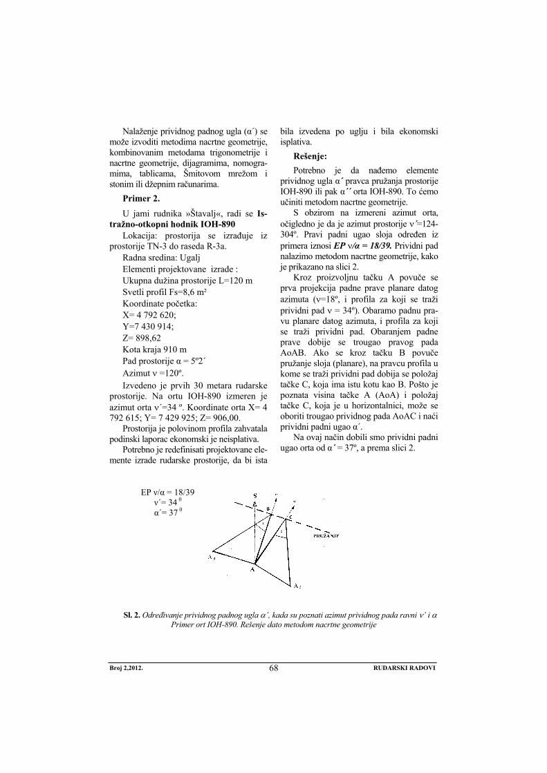
Broj 2,2012. RUDARSKI RADOVI
68
Nalaženje prividnog padnog ugla (α´) se može izvoditi metodima nacrtne geometrije, kombinovanim metodama trigonometrije i nacrtne geometrije, dijagramima, nomogra-mima, tablicama, Šmitovom mrežom i stonim ili džepnim računarima.
Primer 2.
U jami rudnika »Štavalj«, radi se Is-tražno-otkopni hodnik IOH-890
Lokacija: prostorija se izrađuje iz prostorije TN-3 do raseda R-3a.
Radna sredina: Ugalj Elementi projektovane izrade : Ukupna dužina prostorije L=120 m Svetli profil Fs=8,6 m² Koordinate početka: X= 4 792 620; Y=7 430 914; Z= 898,62 Kota kraja 910 m Pad prostorije α = 5º2´ Azimut ν =120º. Izvedeno je prvih 30 metara rudarske
prostorije. Na ortu IOH-890 izmeren je azimut orta ν´=34 º. Koordinate orta X= 4 792 615; Y= 7 429 925; Z= 906,00.
Prostorija je polovinom profila zahvatala podinski laporac ekonomski je neisplativa.
Potrebno je redefinisati projektovane ele-mente izrade rudarske prostorije, da bi ista
bila izvedena po uglju i bila ekonomski isplativa.
Rešenje: Potrebno je da nađemo elemente
prividnog ugla α´ pravca pružanja prostorije IOH-890 ili pak α´´ orta IOH-890. To ćemo učiniti metodom nacrtne geometrije.
S obzirom na izmereni azimut orta, očigledno je da je azimut prostorije ν´=124-304º. Pravi padni ugao sloja određen iz primera iznosi EP ν/α = 18/39. Prividni pad nalazimo metodom nacrtne geometrije, kako je prikazano na slici 2.
Kroz proizvoljnu tačku A povuče se prva projekcija padne prave planare datog azimuta (ν=18º, i profila za koji se traži prividni pad ν = 34º). Obaramo padnu pra-vu planare datog azimuta, i profila za koji se traži prividni pad. Obaranjem padne prave dobije se trougao pravog pada AoAB. Ako se kroz tačku B povuče pružanje sloja (planare), na pravcu profila u kome se traži prividni pad dobija se položaj tačke C, koja ima istu kotu kao B. Pošto je poznata visina tačke A (AoA) i položaj tačke C, koja je u horizontalnici, može se oboriti trougao prividnog pada AoAC i naći prividni padni ugao α´.
Na ovaj način dobili smo prividni padni ugao orta od α´ = 37º, a prema slici 2.
EP ν/α = 18/39 ν΄= 34 0 α΄= 37 0
Slik 2 ΄
Sl. 2. Određivanje prividnog padnog ugla α’, kada su poznati azimut prividnog pada ravni ν’ i α Primer ort IOH-890. Rešenje dato metodom nacrtne geometrije
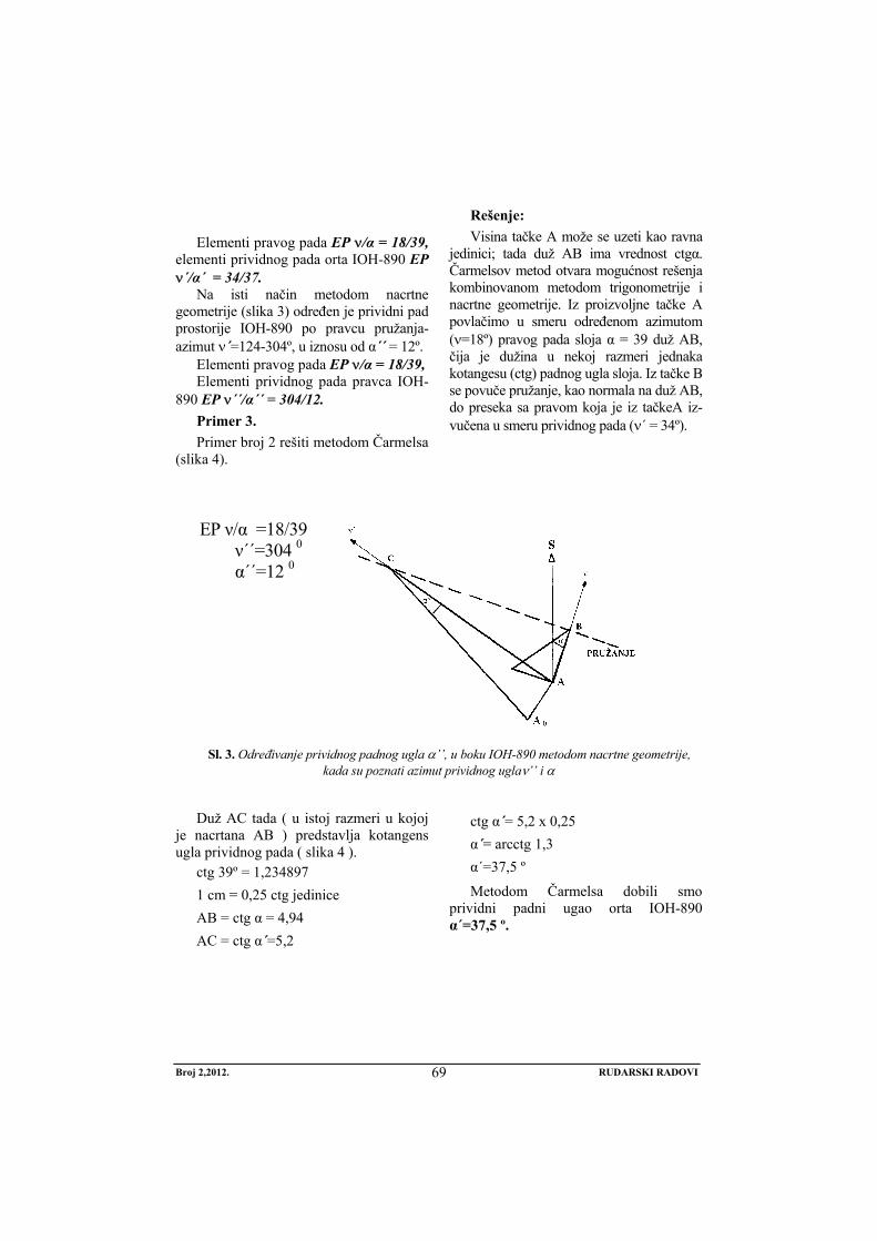
Broj 2,2012. RUDARSKI RADOVI
69
Elementi pravog pada EP ν/α = 18/39,
elementi prividnog pada orta IOH-890 EP ν´/α´ = 34/37.
Na isti način metodom nacrtne geometrije (slika 3) određen je prividni pad prostorije IOH-890 po pravcu pružanja-azimut ν´=124-304º, u iznosu od α´´ = 12º.
Elementi pravog pada EP ν/α = 18/39, Elementi prividnog pada pravca IOH-
890 EP ν´´/α´´ = 304/12. Primer 3. Primer broj 2 rešiti metodom Čarmelsa
(slika 4).
Rešenje: Visina tačke A može se uzeti kao ravna
jedinici; tada duž AB ima vrednost ctgα. Čarmelsov metod otvara mogućnost rešenja kombinovanom metodom trigonometrije i nacrtne geometrije. Iz proizvoljne tačke A povlačimo u smeru određenom azimutom (ν=18º) pravog pada sloja α = 39 duž AB, čija je dužina u nekoj razmeri jednaka kotangesu (ctg) padnog ugla sloja. Iz tačke B se povuče pružanje, kao normala na duž AB, do preseka sa pravom koja je iz tačkeA iz-vučena u smeru prividnog pada (ν´ = 34º).
EP ν/α =18/39 ν΄΄=304 0 α΄΄=12 0
Sl. 3. Određivanje prividnog padnog ugla α’’, u boku IOH-890 metodom nacrtne geometrije, kada su poznati azimut prividnog uglaν’’ i α
Duž AC tada ( u istoj razmeri u kojoj
je nacrtana AB ) predstavlja kotangens ugla prividnog pada ( slika 4 ).
ctg 39º = 1,234897 1 cm = 0,25 ctg jedinice AB = ctg α = 4,94 AC = ctg α´=5,2
ctg α´= 5,2 x 0,25 α´= arcctg 1,3 α´=37,5 º
Metodom Čarmelsa dobili smo prividni padni ugao orta IOH-890 α´=37,5 º.
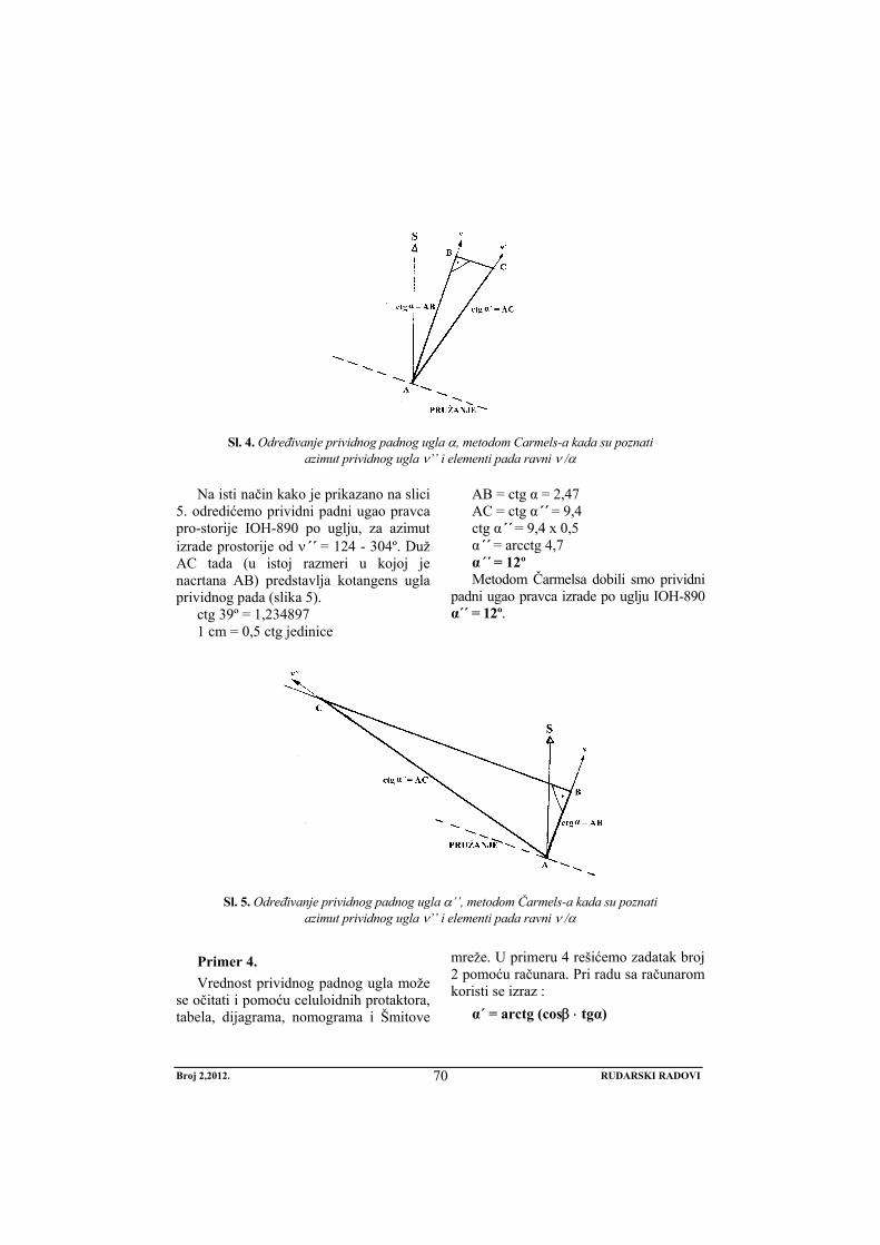
Broj 2,2012. RUDARSKI RADOVI
70
Sl. 4. Određivanje prividnog padnog ugla α, metodom Carmels-a kada su poznati azimut prividnog ugla ν’’ i elementi pada ravni ν /α
Na isti način kako je prikazano na slici 5. odredićemo prividni padni ugao pravca pro-storije IOH-890 po uglju, za azimut izrade prostorije od ν´´ = 124 - 304º. Duž AC tada (u istoj razmeri u kojoj je nacrtana AB) predstavlja kotangens ugla prividnog pada (slika 5).
ctg 39º = 1,234897 1 cm = 0,5 ctg jedinice
AB = ctg α = 2,47 AC = ctg α´´ = 9,4 ctg α´´ = 9,4 x 0,5 α´´ = arcctg 4,7 α´´ = 12º Metodom Čarmelsa dobili smo prividni
padni ugao pravca izrade po uglju IOH-890 α´´ = 12º.
Sl. 5. Određivanje prividnog padnog ugla α’’, metodom Čarmels-a kada su poznati
azimut prividnog ugla ν’’ i elementi pada ravni ν /α
Primer 4. Vrednost prividnog padnog ugla može
se očitati i pomoću celuloidnih protaktora, tabela, dijagrama, nomograma i Šmitove
mreže. U primeru 4 rešićemo zadatak broj 2 pomoću računara. Pri radu sa računarom koristi se izraz :
α´ = arctg (cosβ ⋅ tgα)
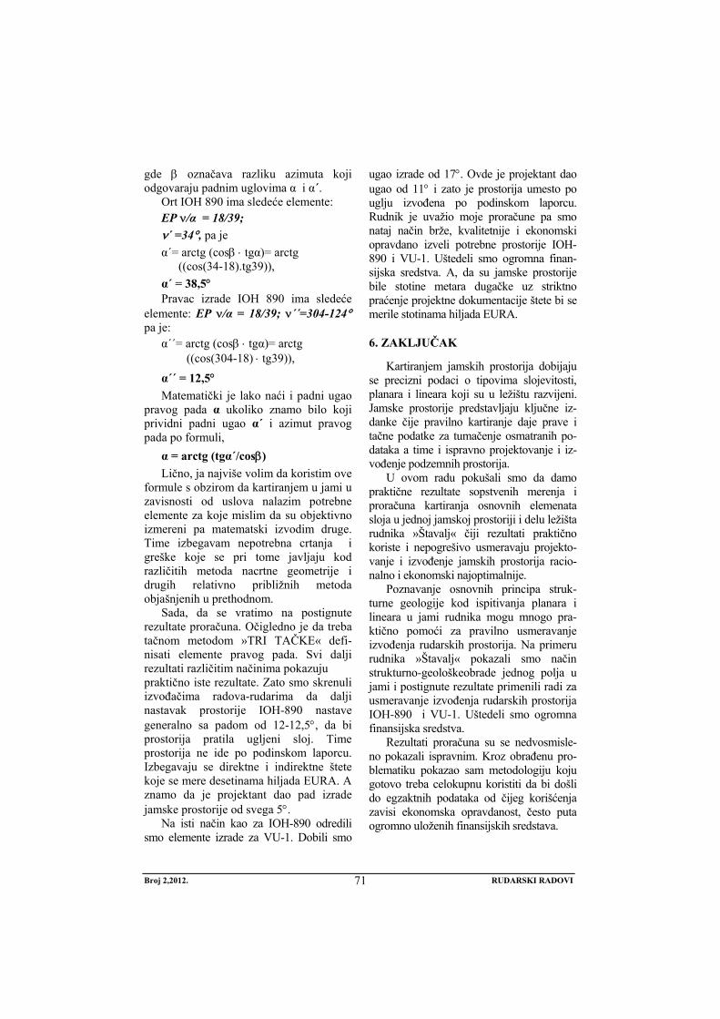
Broj 2,2012. RUDARSKI RADOVI
71
gde β označava razliku azimuta koji odgovaraju padnim uglovima α i α´.
Ort IOH 890 ima sledeće elemente: EP ν/α = 18/39; ν´ =34°, pa je α´= arctg (cosβ ⋅ tgα)= arctg
((cos(34-18).tg39)), α´ = 38,5° Pravac izrade IOH 890 ima sledeće
elemente: EP ν/α = 18/39; ν´´=304-124° pa je:
α´´= arctg (cosβ ⋅ tgα)= arctg ((cos(304-18) ⋅ tg39)),
α´´ = 12,5° Matematički je lako naći i padni ugao
pravog pada α ukoliko znamo bilo koji prividni padni ugao α´ i azimut pravog pada po formuli,
α = arctg (tgα´/cosβ) Lično, ja najviše volim da koristim ove
formule s obzirom da kartiranjem u jami u zavisnosti od uslova nalazim potrebne elemente za koje mislim da su objektivno izmereni pa matematski izvodim druge. Time izbegavam nepotrebna crtanja i greške koje se pri tome javljaju kod različitih metoda nacrtne geometrije i drugih relativno približnih metoda objašnjenih u prethodnom.
Sada, da se vratimo na postignute rezultate proračuna. Očigledno je da treba tačnom metodom »TRI TAČKE« defi-nisati elemente pravog pada. Svi dalji rezultati različitim načinima pokazuju praktično iste rezultate. Zato smo skrenuli izvođačima radova-rudarima da dalji nastavak prostorije IOH-890 nastave generalno sa padom od 12-12,5°, da bi prostorija pratila ugljeni sloj. Time prostorija ne ide po podinskom laporcu. Izbegavaju se direktne i indirektne štete koje se mere desetinama hiljada EURA. A znamo da je projektant dao pad izrade jamske prostorije od svega 5°.
Na isti način kao za IOH-890 odredili smo elemente izrade za VU-1. Dobili smo
ugao izrade od 17°. Ovde je projektant dao ugao od 11° i zato je prostorija umesto po uglju izvođena po podinskom laporcu. Rudnik je uvažio moje proračune pa smo nataj način brže, kvalitetnije i ekonomski opravdano izveli potrebne prostorije IOH-890 i VU-1. Uštedeli smo ogromna finan-sijska sredstva. A, da su jamske prostorije bile stotine metara dugačke uz striktno praćenje projektne dokumentacije štete bi se merile stotinama hiljada EURA.
6. ZAKLJUČAK
Kartiranjem jamskih prostorija dobijaju se precizni podaci o tipovima slojevitosti, planara i lineara koji su u ležištu razvijeni. Jamske prostorije predstavljaju ključne iz-danke čije pravilno kartiranje daje prave i tačne podatke za tumačenje osmatranih po-dataka a time i ispravno projektovanje i iz-vođenje podzemnih prostorija.
U ovom radu pokušali smo da damo praktične rezultate sopstvenih merenja i proračuna kartiranja osnovnih elemenata sloja u jednoj jamskoj prostoriji i delu ležišta rudnika »Štavalj« čiji rezultati praktično koriste i nepogrešivo usmeravaju projekto-vanje i izvođenje jamskih prostorija racio-nalno i ekonomski najoptimalnije.
Poznavanje osnovnih principa struk-turne geologije kod ispitivanja planara i lineara u jami rudnika mogu mnogo pra-ktično pomoći za pravilno usmeravanje izvođenja rudarskih prostorija. Na primeru rudnika »Štavalj« pokazali smo način strukturno-geološkeobrade jednog polja u jami i postignute rezultate primenili radi za usmeravanje izvođenja rudarskih prostorija IOH-890 i VU-1. Uštedeli smo ogromna finansijska sredstva.
Rezultati proračuna su se nedvosmisle-no pokazali ispravnim. Kroz obrađenu pro-blematiku pokazao sam metodologiju koju gotovo treba celokupnu koristiti da bi došli do egzaktnih podataka od čijeg korišćenja zavisi ekonomska opravdanost, često puta ogromno uloženih finansijskih sredstava.
Broj 2,2012. RUDARSKI RADOVI
72
LITERATURA
[1] S. Ćosić, H. Okanović, Modeliranje naponsko-deformacijskog stanja nume-ričkim metodama kod širokočelnog otkopavanja, Časopis Rudarski radovi 2(2010), Bor, str. 53-72.
[2] M. Ivković, Lj. Figun, I. Živojinović, S. Ivković, Optimizacija proizvodno – tehničkih parametara stubne metode otkopavanja ugljenih slojeva, Časopis Rudarski radovi 4(2011), Bor, str. 65-72.
[3] M. Ivković, M. Ljubojev, Ocena ugroženosti eksplozivnom ugljenom prašinom u podzemnim rudnicima uglja u Srbiji, Časopis Rudarski radovi 1(2009), Bor, str. 53-56.
[4] M. Ivković, Application of the
Haulage System With Upper Rales in Mines With Undergraund Explatation, 38th International October Conference on Mining and Metallurgy, Donji Milanovac, 2006, pp. 316-320.
[5] M. Turković, D. Bukumirović, G. Radeka, S. Mušović, Dalji pravci unapređenja podzemne eksploatacije uglja u Sjeničkom ugljenom basenu, Nacionalna konferencija o podzemnoj eksploataciji uglja , Resavica, 2011, str. 49-59.
No 2, 2012. MINING ENGINEERING
73
MINING AND METALLURGY INSTITUTE BOR YU ISSN: 1451-0162 COMMITTEE OF UNDERGROUND EXPLOITATION OF THE MINERAL DEPOSITS UDK: 622
UDK: 622.332:622.261.2(045)=20
Dragomir Bukumirović* , Mensud Turković*, Zdravko Zarić*
STRUCTURAL INVESTIGATION OF SEAMS IN THE PIT OF THE BROWN COAL MINE “ŠTAVALJ”
Abstract
Based on the conducted investigations and experiences, gained by the previous exploitation works in the Sjenica Basin, it is undisputed that the production capacity can be significantly in-creased by previous solution the issues of construction the thermal power facility. Coal reserves and the relatively favorable natural and geological conditions that allow the use of highly mecha-nized technological solutions, which gives the mine a number of comparative advantages over other coal mines in Serbia.
Keywords: underground mining, underground facilities, indirect measuring, natural fall angle
* JP PEU Resavica, Mine“Štavalj“- Sjenica JP PEU Resavica, Mine“Štavalj“- Sjenica *JP PEU Resavica, Mine of Brown coal „Rembas“
1. INTRODUCTION
The underground facilities present the excellent continuous shoots, often many kilometers long, but also localized to al-low introduction and investigation the deposit only under strictly defined and limited ways. The image of deposit geol-ogy that a geologist create during the mapping is not just an optional assump-tion of geological composition and struc-ture of a particular field, but a view on which often very extensive and expensive investments depend and that the first fur-ther investigations will subject on a strict control and check the correctness of as-sumptions and solutions.
The main task of a miner geologist is constantly monitoring and solution the de-posit geology by mapping the underground
facilities. This is a very responsible job that requires careful preparation and precise execution using the all geological methods that can help solving many issues of de-posit - structural and genetic, theoretical and practical, related to solution the masses in deposit, important for further investiga-tion and mining. Fresh constructed under-ground facilities provide the most informa-tion, and therefore recording is performed in parallel with the progress of mining works.
In addition to the geological structure and field history, mapping of the under-ground facilities should provide informa-tion with practical significance of mineral resources and engineering-geological, hydrogeological and geomorphological
No 2, 2012. MINING ENGINEERING
74
characteristics of the deposit. He most important investigations are those related to mineral resources; others are commonly reduced to the quotation of certain phe-nomena and properties, unless the fields are extremely interesting from the view-point of some of these disciplines.
Mapping of the mine facilities gives the precise data on types of stratification, planars and linears, which are developed in deposit. Mine facilities are the key shoots whose proper mapping gives the true and accurate information for interpre-tation of the observed data and thus the proper design and construction of under-ground facilities.
2. DEFINING THE SPATIAL ORIENTATION OF LINEAR AND PLANAR
Spatial orientation of linear and planar elements is shown by their elements of fall – azimuth of fall and azimuth angle.
Locus of points with the same elevation on a geological plane is called rendering; normal to rendering in the measuring plane is a fall plane. Its elements of fall also de-termine the elements of a plane fall.
Azimut of fall (ν) is a horizontal angle inclinated by geological linear or fall right with meridian, measured from the meridian of the clockwise direction. It can range 0-360º.
Fall angle (α) is vertical between hori-zontal plane amd geological linear, i.e. the fall right of geological planar. Its values amount to 0-90.
Elements of the fall are written as: the azimuth of fall/fall angle (for example 234/47).
3. MEASURING ACCURACY OF FALL ELEMENTS
Several factors affect the accuracy of measurement the elements of fall. These are primarily subjective psychological fac-tors, the measured surface representation,
the compass accuracy, the presence of magnetic anomaly.
Measurement conditions are often un-suitable in the pit (atmospheric conditions, moisture, dust, lack of oxygen, light, pres-ence of metals, sticky, fatigue, etc.). On the other hand, some compasses are marked only at angles of 5° on the scale, and these errors should be addressed.
Representativeness of the measured surface is of the utmost importance. Geo-logical planar surfaces can be uneven be-cause of how they are physically distinct, even though the same as a whole ideal geometrical plane. Even the statistical measurement of dozens the fall elements may give questionable results.
Due to this in the practice of the mine "Štavalj", knowing the global structure and tectonics of the entire deposit and its individual parts, the other methods of indirect measurement of elements were used in the decametric and hectometric measuring area and the results are ob-tained that in practical term unmistakably direct mining works..
4. INDIRECT MEASURING THE FALL ELEMENTS USING THE “THREE POINT” METHOD
In geological maps, situational plans of pit or deep drilling, where three points can be obtained that lie in a seam with known planimetric coordinates and elevations, the indirect method of measuring the elements of seam fall can be applied. If a planar be-tween them is not broken and dislocated by the fault, or more in larger scale wrinkled, these three points define a seam plane and their fall elements can be determined using them.
The solution is obtained by finding the horizontal right in this plane, which then shows the extension and breaking of fall right in a horizontal in order to determine the fall angle. This problem to be solved techni-cally in several ways, which are reduced to
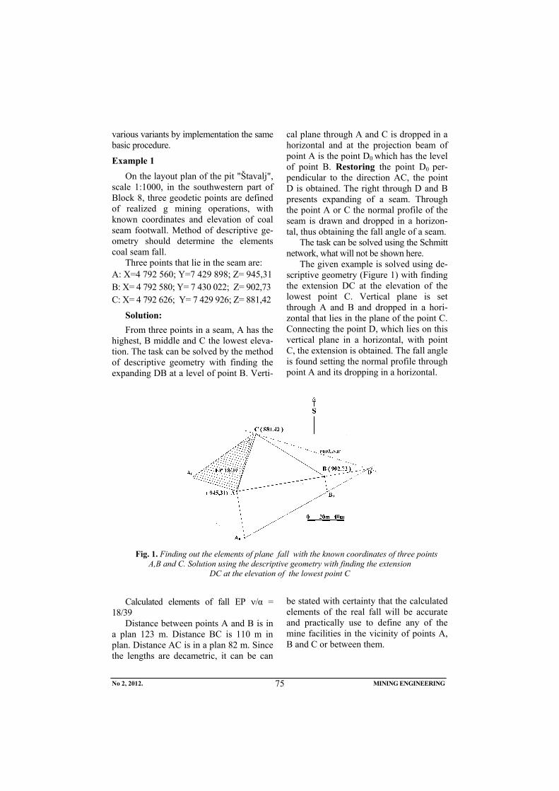
No 2, 2012. MINING ENGINEERING
75
various variants by implementation the same basic procedure.
Example 1 On the layout plan of the pit "Štavalj",
scale 1:1000, in the southwestern part of Block 8, three geodetic points are defined of realized g mining operations, with known coordinates and elevation of coal seam footwall. Method of descriptive ge-ometry should determine the elements coal seam fall.
Three points that lie in the seam are: A: X=4 792 560; Y=7 429 898; Z= 945,31 B: X= 4 792 580; Y= 7 430 022; Z= 902,73 C: X= 4 792 626; Y= 7 429 926; Z= 881,42
Solution: From three points in a seam, A has the
highest, B middle and C the lowest eleva-tion. The task can be solved by the method of descriptive geometry with finding the expanding DB at a level of point B. Verti-
cal plane through A and C is dropped in a horizontal and at the projection beam of point A is the point D0 which has the level of point B. Restoring the point D0 per-pendicular to the direction AC, the point D is obtained. The right through D and B presents expanding of a seam. Through the point A or C the normal profile of the seam is drawn and dropped in a horizon-tal, thus obtaining the fall angle of a seam.
The task can be solved using the Schmitt network, what will not be shown here.
The given example is solved using de-scriptive geometry (Figure 1) with finding the extension DC at the elevation of the lowest point C. Vertical plane is set through A and B and dropped in a hori-zontal that lies in the plane of the point C. Connecting the point D, which lies on this vertical plane in a horizontal, with point C, the extension is obtained. The fall angle is found setting the normal profile through point A and its dropping in a horizontal.
Slik 1
Fig. 1. Finding out the elements of plane fall with the known coordinates of three points A,B and C. Solution using the descriptive geometry with finding the extension
DC at the elevation of the lowest point C
Calculated elements of fall EP ν/α = 18/39
Distance between points A and B is in a plan 123 m. Distance BC is 110 m in plan. Distance AC is in a plan 82 m. Since the lengths are decametric, it can be can
be stated with certainty that the calculated elements of the real fall will be accurate and practically use to define any of the mine facilities in the vicinity of points A, B and C or between them.
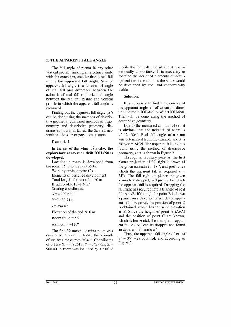
No 2, 2012. MINING ENGINEERING
76
5. THE APPARENT FALL ANGLE
The fall angle of planar in any other vertical profile, making an arbitrary angle with the extension, smaller than a real fall - it is the apparent fall angle. Size of apparent fall angle is a function of angle of real fall and difference between the azimuth of real fall or horizontal angle between the real fall planar and vertical profile in which the apparent fall angle is measured
Finding out the apparent fall angle (α ') can be done using the methods of descrip-tive geometry, combined methods of trigo-nometry and descriptive geometry, dia-grams nomograms, tables, the Schmitt net-work and desktop or pocket calculators.
Example 2
In the pit of the Mine »Štavalj«, the exploratory-excavation drift IOH-890 is developed.
Location: a room is developed from the room TN-3 to the fault R-3a.
Working environment: Coal Elements of designed development: Total length of a room L=120 m Bright profile Fs=8.6 m² Starting coordinates: X= 4 792 620; Y=7 430 914; Z= 898.62 Elevation of the end: 910 m Room fall α = 5º2´ Azimuth ν =120º
The first 30 meters of mine room was developed. On ort IOH-890, the azimuth of ort was measuredν´=34 º. Coordinates of ort are X = 4792615, Y = 7429925, Z = 906.00. A room was included by a half of
profile the footwall of marl and it is eco-nomically unprofitable. It is necessary to redefine the designed elements of devel-opment the mine room as the same would be developed by coal and economically viable.
Solution:
It is necessary to find the elements of the apparent angle α ' of extension direc-tion the room IOH-890 or α'' ort IOH-890. This will be done using the method of descriptive geometry.
Due to the measured azimuth of ort, it is obvious that the azimuth of room is ν´=124-304º. Real fall angle of a seam was determined from the example and it is EP ν/α = 18/39. The apparent fall angle is found using the method of descriptive geometry, as it is shown in Figure 2.
Through an arbitrary point A, the first planar projection of fall right is drawn of the given azimuth (ν=18 º, and profile for which the apparent fall is required ν = 34º). The fall right of planar the given azimuth is dropped, and profile for which the apparent fall is required. Dropping the fall right has resulted into a triangle of real fall AoAB. If through the point B is drawn a planar on a direction in which the appar-ent fall is required, the position of point C is obtained, which has the same elevation as B. Since the height of point A (AoA) and the position of point C are known, which is horizontal, the triangle of appar-ent fall AOAC can be dropped and found an apparent fall angle α '.
Thus, the apparent fall angle of ort of α´ = 37º was obtained, and according to Figure 2.
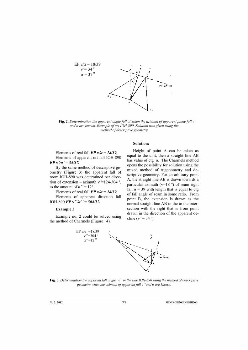
No 2, 2012. MINING ENGINEERING
77
EP ν/α = 18/39 ν΄= 34 0 α΄= 37 0
Fig. 2. Determination the apparent angle fall α΄,when the azimuth of apparent plane fall ν΄
and α are known. Example of ort IOH-890. Solution was given using the method of descriptive geometry
Elements of real fall EP ν/α = 18/39, Elements of apparent ort fall IOH-890
EP ν´/α´ = 34/37. By the same method of descriptive ge-
ometry (Figure 3) the apparent fall of room IOH-890 was determined per direc-tion of extension – azimuth ν´=124-304 º, to the amount of α´´ = 12º.
Elements of real fall EP ν/α = 18/39, Elements of apparent direction fall
IOH-890 EP ν´´/α´´ = 304/12.
Example 3
Example no. 2 could be solved using the method of Charmels (Figure 4).
Solution:
Height of point A can be taken as equal to the unit, then a straight line AB has value of ctg α. The Charmels method opens the possibility for solution using the mixed method of trigonometry and de-scriptive geometry. For an arbitrary point A, the straight line AB is drawn towards a particular azimuth (ν=18 º) of seam right fall α = 39 with length that is equal to ctg of fall angle of seam in some ratio. From point B, the extension is drawn as the normal straight line AB to the to the inter-section with the right that is from point drawn in the direction of the apparent de-cline (ν´ = 34 º).
EP ν/α =18/39 ν΄΄=304 0 α΄΄=12 0
Fig. 3. Determination the apparent fall angle α΄΄in the side IOH-890 using the method of descriptive geometry when the azimuth of apparent fall ν΄΄and α are known.
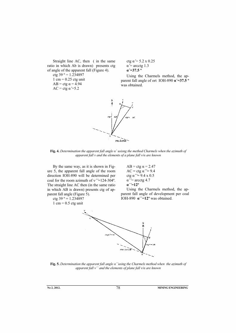
No 2, 2012. MINING ENGINEERING
78
Straight line AC, then ( in the same
ratio in which Ab is drawn) presents ctg of angle of the apparent fall (Figure 4).
ctg 39 º = 1.234897 1 cm = 0.25 ctg unit AB = ctg α = 4.94 AC = ctg α´=5.2
ctg α´= 5.2 x 0.25 α´= arcctg 1.3 α´=37.5 º Using the Charmels method, the ap-
parent fall angle of ort IOH-890 α´=37.5 º was obtained.
Fig. 4. Determination the apparent fall angle α΄ usisng the method Charmels when the azimuth of apparent fall ν and the elements of a plane fall ν/α are known
By the same way, as it is shown in Fig-
ure 5, the apparent fall angle of the room direction IOH-890 will be determined per coal for the room azimuth of ν´´=124-304º. The straight line AC then (in the same ratio in which AB is drawn) presents ctg of ap-parent fall angle (Figure 5).
ctg 39 º = 1.234897 1 cm = 0.5 ctg unit
AB = ctg α = 2.47 AC = ctg α´´= 9.4 ctg α´´= 9.4 x 0.5 α´´= arcctg 4.7 α´´=12º Using the Charmels method, the ap-
parent fall angle of development per coal IOH-890 α´´=12º was obtained.
Fig. 5. Determination the apparent fall angle α΄΄using the Charmels method when the azimuth of
apparent fall ν΄΄ and the elements of plane fall ν/α are known
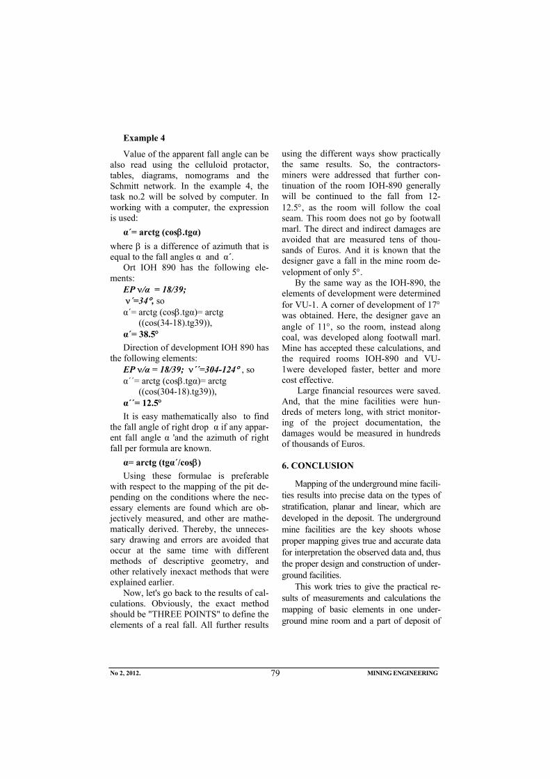
No 2, 2012. MINING ENGINEERING
79
Example 4
Value of the apparent fall angle can be also read using the celluloid protactor, tables, diagrams, nomograms and the Schmitt network. In the example 4, the task no.2 will be solved by computer. In working with a computer, the expression is used:
α´= arctg (cosβ.tgα) where β is a difference of azimuth that is equal to the fall angles α and α´.
Ort IOH 890 has the following ele-ments:
EP ν/α = 18/39; ν´=34°, so α´= arctg (cosβ.tgα)= arctg
((cos(34-18).tg39)), α´= 38.5° Direction of development IOH 890 has
the following elements: EP ν/α = 18/39; ν´´=304-124° , so α´´= arctg (cosβ.tgα)= arctg
((cos(304-18).tg39)), α´´= 12.5° It is easy mathematically also to find
the fall angle of right drop α if any appar-ent fall angle α 'and the azimuth of right fall per formula are known.
α= arctg (tgα´/cosβ) Using these formulae is preferable
with respect to the mapping of the pit de-pending on the conditions where the nec-essary elements are found which are ob-jectively measured, and other are mathe-matically derived. Thereby, the unneces-sary drawing and errors are avoided that occur at the same time with different methods of descriptive geometry, and other relatively inexact methods that were explained earlier.
Now, let's go back to the results of cal-culations. Obviously, the exact method should be "THREE POINTS" to define the elements of a real fall. All further results
using the different ways show practically the same results. So, the contractors-miners were addressed that further con-tinuation of the room IOH-890 generally will be continued to the fall from 12-12.5°, as the room will follow the coal seam. This room does not go by footwall marl. The direct and indirect damages are avoided that are measured tens of thou-sands of Euros. And it is known that the designer gave a fall in the mine room de-velopment of only 5°.
By the same way as the IOH-890, the elements of development were determined for VU-1. A corner of development of 17° was obtained. Here, the designer gave an angle of 11°, so the room, instead along coal, was developed along footwall marl. Mine has accepted these calculations, and the required rooms IOH-890 and VU-1were developed faster, better and more cost effective.
Large financial resources were saved. And, that the mine facilities were hun-dreds of meters long, with strict monitor-ing of the project documentation, the damages would be measured in hundreds of thousands of Euros.
6. CONCLUSION
Mapping of the underground mine facili-ties results into precise data on the types of stratification, planar and linear, which are developed in the deposit. The underground mine facilities are the key shoots whose proper mapping gives true and accurate data for interpretation the observed data and, thus the proper design and construction of under-ground facilities.
This work tries to give the practical re-sults of measurements and calculations the mapping of basic elements in one under-ground mine room and a part of deposit of
No 2, 2012. MINING ENGINEERING
80
the mine »Štavalj«, whose results are used for correct design and development the un-derground facilities as the rational and eco-nomically the most optimum.
Knowing the basic principles of struc-tural geology study of planar and linear in the pit of the mine have much practical help for the proper routing performance of mining facilities. In the example of the mine »Štavalj", the structural-geological processing of a field in the pit and the ob-tained results were shown in the use for routing performance of the mine facilities IOH-890 and V-1. Large financial re-sources were saved..
The calculation results are shown as undoubtedly correct. Through procesed the methodology was shown that should be almost complete use to get to the exact data whose use depends on the economic justification, often times a huge invested financial assets..
REFERENCES
[1] S. Ćosić, H. Okanović, Modeling of Stress-Deformation State Using the Numerical Methods in the Wide Face Mining, Mining Engineering, 2(2010), Bor, pp. 73-92.
[2] M. Ivković, Lj. Figun, I. Živojinović, S. Ivković, Optimization of Natural – Tehnical Parameters for the Pillar Method of Coal Excavation, Mining Engineering, 4(2011), Bor, pp. 73-80.
[3] M. Ivković, M. Ljubojev, Endanger Evaluation of Explosive Coal Dust in Underground Coal-Mines in Serbia, Mining Engineering, 1(2009), Bor, pp. 53-56.
[4] M. Ivković, Application of the Haul-age System With Upper Rales in Mines With Undergraund Explatation, 38th International October Conference on Mining and Metallurgy, Donji Mi-lanovac, 2006, pp. 316-320.
[5] M. Turkovic, D. Bukumirovic, G. Radeka, S. Musovic, Further Direc-tions of Improvement the Underground Coal Mining in the Sjenica Coal Basin, National Conference on Underground Coal Mining, Resavica, 2011, pp. 49-59 (in Serbian)
Broj 2,2012. RUDARSKI RADOVI
81
INSTITUT ZA RUDARSTVO I METALURGIJU BOR YU ISSN: 1451-0162 KOMITET ZA PODZEMNU EKSPLOATACIJU MINERALNIH SIROVINA UDK: 622
UDK:622.33:622.272:662.87(045)=861
Mirko Ivković*, Mile Bugarin**, Sead Softić***
NOVA METODOLOGIJA OCENE UGROŽENOSTI EKSPLOZIVNOM UGLJENOM PRAŠINOM U JAMAMA RMU „REMBAS“ – RESAVICA
Izvod
U radu se obrađuje postojeći pristup oceni ugroženosti od eksplozivne prašine koji se sada primenjuje u jamama RMU „Rembas“ – Resavica, daje ocena njegove primenljivosti, kao i predlozi za odgovarajuće izmene.
Ključne reči: ugljena prašina, ugalj, rudnik, eksplozivna prašina
* JP PEU Resavica ** Institut za rudarstvo i metalurgiju Bor *** Rudnik Mrkog uglja Đurđevik
UVOD
Resavsko-moravski ugljeni basen nalazi se u zapadnim delovima istočne Srbije i u geografskom smislu basen se prostire od se-la Lipovica i Panjevac na severu do Često-brodice i Smoljinca na jugu. Ukupna dužina basena iznosi 45 km, a širina oko 7 km. Sedište basena je u Resavici, a admini-strativni centar ove oblasti je Despotovac.
Eksploatacija uglja u sklopu basena odvija se na prostoru koji sada obuhvata četiri ležišta:
- Strmosten, - Jelovac, - Ravna Reka – IV blok, i - Senjski rudnik.
Ležišta Strmosten i Jelovac obuhvataju severni deo Resavsko - moravskog ugljono-snog basena, a nalaze se na jugozapadnim padinama planine Beljanica. Ležište Senjski rudnik obuhvata južni deo basena, a Ravna reka – IV blok centralni deo. Sva četiri
ugljonosna ležišta su potkopima (Strmo-stenski, Jelovački, Bučarski, Severni i Južni) povezani sa Separacijom u Resavici.
Geološku građu basena čine različite litostratigrafske jedinice paleozojske, mezo-zojske i kenozojske starosti. Paleozoik je predstavljen formacijom permskih crvenih peščara koji imaju najveće rasprostranjenje. Mezozoik je predstavljen jurskim krečnja-cima uklještenim u okviru krljušti u crvenim peščarima i donjokrednim krečnjacima.
Kenozoik je predstavljen stenama tercijara i kvartara. U okviru tercijara izdvojeni su andenziti uslovno paleogene starosti i ugljonosna miocenska serija. Po litološkom sastavu i superpoziciji slojeva ugljonosna miocenska serija predstavljena je sa više odeljaka, i to:
- bazalni odeljak, - podina ugljenog sloja, - ugljeni sloj, - krovina ugljenog sloja
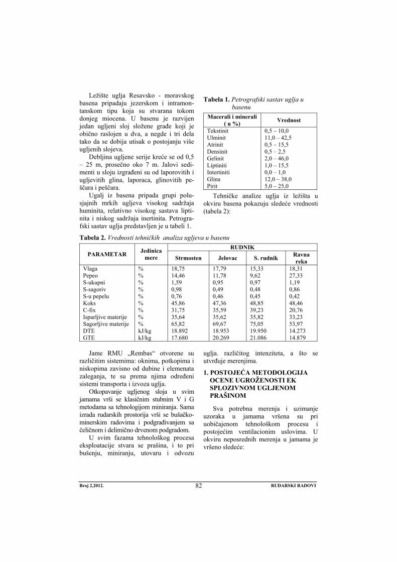
Broj 2,2012. RUDARSKI RADOVI
82
Ležište uglja Resavsko - moravskog basena pripadaju jezerskom i intramon-tanskom tipu koja su stvarana tokom donjeg miocena. U basenu je razvijen jedan ugljeni sloj složene građe koji je obično raslojen u dva, a negde i tri dela tako da se dobija utisak o postojanju više ugljenih slojeva.
Debljina ugljene serije kreće se od 0,5 – 25 m, prosečno oko 7 m. Jalovi sedi-menti u sloju izgrađeni su od laporovitih i ugljevitih glina, laporaca, glinovitih pe-ščara i peščara.
Ugalj iz basena pripada grupi polu-sjajnih mrkih ugljeva visokog sadržaja huminita, relativno visokog sastava lipti-nita i niskog sadržaja inertinita. Petrogra-fski sastav uglja predstavljen je u tabeli 1.
Tabela 1. Petrografski sastav uglja u basenu
Macerali i minerali ( u %) Vrednost
Tekstinit Ulminit Atrinit Densinit Gelinit Liptiniti Intertiniti Glina Pirit
0,5 – 10,0 11,0 – 42,5 0,5 – 15,5 0,5 – 2,5 2,0 – 46,0 1,0 – 15,5 0,0 – 1,0 12,0 – 38,0 5,0 – 25,0
Tehničke analize uglja iz ležišta u okviru basena pokazuju sledeće vrednosti (tabela 2):
Tabela 2. Vrednosti tehničkih analiza ugljeva u basenu RUDNIK
PARAMETAR Jedinica mere Strmosten Jelovac S. rudnik Ravna
reka Vlaga Pepeo S-ukupni S-sagoriv S-u pepelu Koks C-fix Isparljive materije Sagorljive materije DTE GTE
% % % % % % % % % kJ/kg kJ/kg
18,75 14,46 1,59 0,98 0,76 45,86 31,75 35,64 65,82 18.892 17.680
17,79 11,78 0,95 0,49 0,46 47,36 35,59 35,62 69,67 18.953 20.269
15,33 9,62 0,97 0,48 0,45 48,85 39,23 35,82 75,05 19.950 21.086
18,31 27,33 1,19 0,86 0,42 48,46 20,76 33,23 53,97 14.273 14.879
Jame RMU „Rembas“ otvorene su
različitim sistemima: oknima, potkopima i niskopima zavisno od dubine i elemenata zaleganja, te su prema njima određeni sistemi transporta i izvoza uglja.
Otkopavanje ugljenog sloja u svim jamama vrši se klasičnim stubnim V i G metodama sa tehnologijom miniranja. Sama izrada rudarskih prostorija vrši se bušačko-minerskim radovima i podgrađivanjem sa čeličnom i delimično drvenom podgradom.
U svim fazama tehnološkog procesa eksploatacije stvara se prašina, i to pri bušenju, miniranju, utovaru i odvozu
uglja. različitog intenziteta, a što se utvrđuje merenjima.
1. POSTOJEĆA METODOLOGIJA OCENE UGROŽENOSTI EK SPLOZIVNOM UGLJENOM PRAŠINOM
Sva potrebna merenja i uzimanje uzoraka u jamama vršena su pri uobičajenom tehnološkom procesu i postojećim ventilacionim uslovima. U okviru neposrednih merenja u jamama je vršeno sledeće:
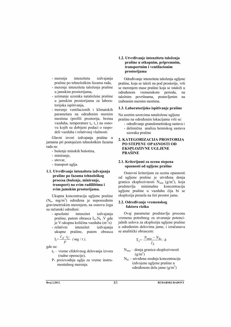
Broj 2,2012. RUDARSKI RADOVI
83
- merenja intenziteta izdvajanja
prašine po tehnološkim fazama rada, - merenje intenziteta taloženja prašine
u jamskim prostorijama, - uzimanje uzoraka nataložene prašine
u jamskim prostorijama za labora-torijska ispitivanja,
- merenje ventilacionih i klimatskih parametara na određenim mernim mestima (profili prostorija, brzina vazduha, temperature ts, tv,) na osno-vu kojih su dobijeni podaci o raspo-deli vazduha i relativnoj vlažnosti.
Glavni izvori izdvajanja prašine u jamama pri postojećem tehnološkim fazama rada su:
- bušenje minskih bušotina, - miniranje, - utovar, - transport uglja.
1.1. Utvrđivanje intenziteta izdvajanja prašine po fazama tehnološkog procesa (bušenje, miniranje, transport) na svim radilištima i svim jamskim prostorijama.
Ukupna koncentracija ugljene prašine (Nk, mg/m3) određena je neposrednim gravimetriskim merenjem, na osnovu čega su računski određeni:
- apsolutni intenzitet izdvajanja prašine, putem obrasca IA=Nk .V gde je V-ukupna količina vazduha (m3/s)
- relativni intenzitet izdvajanja ukupne prašine, putem obrasca
Ir= ),t/mg(P
tI CA ⋅
gde su: tC – vreme efektivnog delovanja izvora
(radne operacije), P- proizvodnja uglja za vreme instru-
mentalnog merenja.
1.2. Utvrđivanje intenziteta taloženja prašine u otkopnim, pripremnim, transportnim i ventilacionim prostorijama
Određivanje intenziteta taloženja ugljene prašine, koja se taloži na pod prostorije, vrši se merenjem mase prašine koja se istaloži u određenom vremenskom periodu, na taložnim površinama, postavljenim na izabranim mernim mestima.
1.3. Laboratorijsko ispitivanje prašine
Na uzetim uzorcima nataložene ugljene prašine na određenim lokacijama vrši se:
- određivanje granulometriskog sastava i - delimična analiza hemiskog sastava
uzoraka prašine
2. KATEGORIZACIJA PROSTORIJA PO STEPENU OPASNOSTI OD EKSPLOZIVNE UGLJENE PRAŠINE
2.1. Kriterijumi za ocenu stepena opasnosti od ugljene prašine
Osnovni kriterijum za ocenu opasnosti od ugljene prašine je utvrđena donja granica eksplozivnosti Nmin (g/m3), koja predstavlja minimalnu koncentraciju ugljene prašine u vazduhu čija bi se eksplozija prenela na širi prostor jame.
2.2. Određivanje vremenskog faktora rizika
Ovaj parametar predstavlja procenu vremena potrebnog za stvaranje potenci-jalnih uslova za eksploziju ugljene prašine u određenim delovima jame, i izračunava se analitički obrascem:
To= hI
NN
S
ksmin ⋅−
Nmin – donja granica eksplozivnosti (g/m3)
Nks – utvrđena srednja koncentracija izdvojene ugljene prašine u određenom delu jame (g/m3)
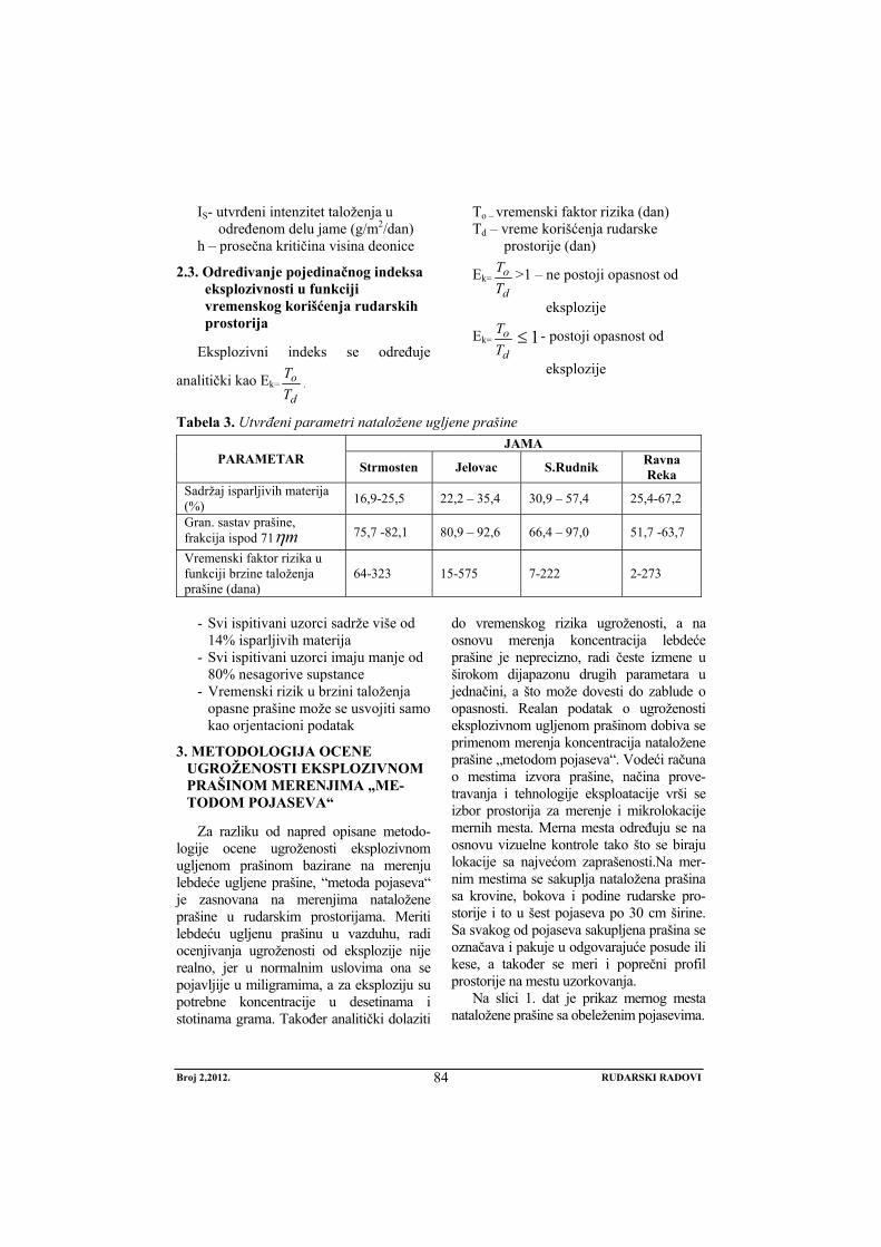
Broj 2,2012. RUDARSKI RADOVI
84
IS- utvrđeni intenzitet taloženja u određenom delu jame (g/m2/dan)
h – prosečna kritičina visina deonice
2.3. Određivanje pojedinačnog indeksa eksplozivnosti u funkciji vremenskog korišćenja rudarskih prostorija
Eksplozivni indeks se određuje
analitički kao Ek=d
oTT
.
To – vremenski faktor rizika (dan) Td – vreme korišćenja rudarske
prostorije (dan)
Ek=d
oTT >1 – ne postoji opasnost od
eksplozije
Ek=d
oTT 1≤ - postoji opasnost od
eksplozije
Tabela 3. Utvrđeni parametri nataložene ugljene prašine JAMA
PARAMETAR Strmosten Jelovac S.Rudnik Ravna Reka
Sadržaj isparljivih materija (%) 16,9-25,5 22,2 – 35,4 30,9 – 57,4 25,4-67,2
Gran. sastav prašine, frakcija ispod 71 mη 75,7 -82,1 80,9 – 92,6 66,4 – 97,0 51,7 -63,7
Vremenski faktor rizika u funkciji brzine taloženja prašine (dana)
64-323 15-575 7-222 2-273
- Svi ispitivani uzorci sadrže više od
14% isparljivih materija - Svi ispitivani uzorci imaju manje od
80% nesagorive supstance - Vremenski rizik u brzini taloženja
opasne prašine može se usvojiti samo kao orjentacioni podatak
3. METODOLOGIJA OCENE UGROŽENOSTI EKSPLOZIVNOM PRAŠINOM MERENJIMA „ME-TODOM POJASEVA“
Za razliku od napred opisane metodo-logije ocene ugroženosti eksplozivnom ugljenom prašinom bazirane na merenju lebdeće ugljene prašine, “metoda pojaseva“ je zasnovana na merenjima nataložene prašine u rudarskim prostorijama. Meriti lebdeću ugljenu prašinu u vazduhu, radi ocenjivanja ugroženosti od eksplozije nije realno, jer u normalnim uslovima ona se pojavljije u miligramima, a za eksploziju su potrebne koncentracije u desetinama i stotinama grama. Također analitički dolaziti
do vremenskog rizika ugroženosti, a na osnovu merenja koncentracija lebdeće prašine je neprecizno, radi česte izmene u širokom dijapazonu drugih parametara u jednačini, a što može dovesti do zablude o opasnosti. Realan podatak o ugroženosti eksplozivnom ugljenom prašinom dobiva se primenom merenja koncentracija nataložene prašine „metodom pojaseva“. Vodeći računa o mestima izvora prašine, načina prove-travanja i tehnologije eksploatacije vrši se izbor prostorija za merenje i mikrolokacije mernih mesta. Merna mesta određuju se na osnovu vizuelne kontrole tako što se biraju lokacije sa najvećom zaprašenosti.Na mer-nim mestima se sakuplja nataložena prašina sa krovine, bokova i podine rudarske pro-storije i to u šest pojaseva po 30 cm širine. Sa svakog od pojaseva sakupljena prašina se označava i pakuje u odgovarajuće posude ili kese, a također se meri i poprečni profil prostorije na mestu uzorkovanja.
Na slici 1. dat je prikaz mernog mesta nataložene prašine sa obeleženim pojasevima.
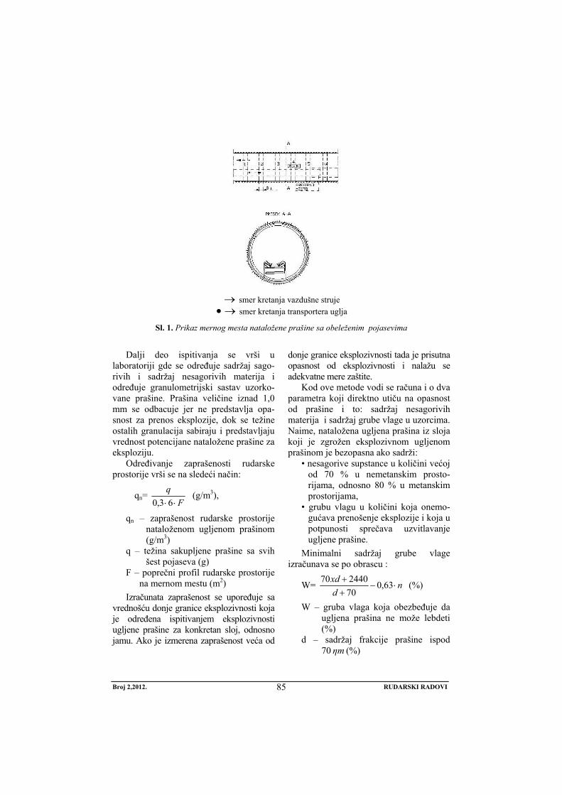
Broj 2,2012. RUDARSKI RADOVI
85
→ smer kretanja vazdušne struje →• smer kretanja transportera uglja
Sl. 1. Prikaz mernog mesta nataložene prašine sa obeleženim pojasevima
Dalji deo ispitivanja se vrši u
laboratoriji gde se određuje sadržaj sago-rivih i sadržaj nesagorivih materija i određuje granulometrijski sastav uzorko-vane prašine. Prašina veličine iznad 1,0 mm se odbacuje jer ne predstavlja opa-snost za prenos eksplozije, dok se težine ostalih granulacija sabiraju i predstavljaju vrednost potencijane nataložene prašine za eksploziju.
Određivanje zaprašenosti rudarske prostorije vrši se na sledeći način:
qn= F
q⋅⋅63,0
(g/m3),
qn – zaprašenost rudarske prostorije nataloženom ugljenom prašinom (g/m3)
q – težina sakupljene prašine sa svih šest pojaseva (g)
F – poprečni profil rudarske prostorije na mernom mestu (m2)
Izračunata zaprašenost se upoređuje sa vrednošću donje granice eksplozivnosti koja je određena ispitivanjem eksplozivnosti ugljene prašine za konkretan sloj, odnosno jamu. Ako je izmerena zaprašenost veća od
donje granice eksplozivnosti tada je prisutna opasnost od eksplozivnosti i nalažu se adekvatne mere zaštite.
Kod ove metode vodi se računa i o dva parametra koji direktno utiču na opasnost od prašine i to: sadržaj nesagorivih materija i sadržaj grube vlage u uzorcima. Naime, nataložena ugljena prašina iz sloja koji je zgrožen eksplozivnom ugljenom prašinom je bezopasna ako sadrži:
• nesagorive supstance u količini većoj od 70 % u nemetanskim prosto-rijama, odnosno 80 % u metanskim prostorijama,
• grubu vlagu u količini koja onemo-gućava prenošenje eksplozije i koja u potpunosti sprečava uzvitlavanje ugljene prašine.
Minimalni sadržaj grube vlage izračunava se po obrascu :
W= ndxd
⋅−++ 63,070244070 (%)
W – gruba vlaga koja obezbeđuje da ugljena prašina ne može lebdeti (%)
d – sadržaj frakcije prašine ispod 70 mη (%)
Broj 2,2012. RUDARSKI RADOVI
86
n – sadržajnesagorivih čestica u uglje- noj prašini (%)
Ukoliko nisu ispunjeni navedeni uslovi tada je uzorkovana ugljena na mernom mestu opasna.
ZAKLJUČAK
Utvrđivanje, odnosno ocena ugrože-nosti eksplozivnom ugljenom prašinom podzemnih rudarskih prostorija je složen i odgovoran zadatak tehničkog osoblja ru-dnika, koje mora blagovremeno doneti i sprovesti odgovarajuće mere zaštite. Me-todologija merenja koncentracija lebdeće
prašine i analitički izraz o oceni opasnosti u samom pristupu ima niz nepoznanica, te se u ovom radu prišlo njenoj analizi i razradi metodologije zasnovane na merenju nataložene prašine u rudarskim prostorijama „metodom pojaseva“.
Ispitivanjima u laboratorijskim uslovima po standardizovanoj metodi utvrđeno je da je ugljena prašina u sve četiri jame RMU „Rembas“ pod određenim uslovima eksplo-zivno opasna. Donja granica eksplozivnosti za ugljenu prašinu iz ovih jama prikazana je u tabeli 4.
Tabela 4. Parametri eksplozivnosti ugljene prašine u jamama RMU „Rembas“ JAMA
KARAKTERISTIKA Strmosten Jelovac S.Rudnik Ravna Reka
Donja granica eksplozivnosti prašina (g/m3) u sistemu • prašina – vazduh • prašina – vazduh – 2% CH4
200 125
300 200
320 180
- 100
Utvrđena donja granica eksplozivnosti
upoređuje se sa količinom ugljene prašine prikupljene na mernim mestima i daje ocena u stvarnom stanju zaprašenosti.
LITERATURA
[1] Ćurčić A.: Industriske prašine kao potencijalni izvori opasnosti od eksplozija, Zbornik savetovanja „Požari i eksplozije“, Budva, 1987
[2] Ćurčić A.: Istraživanje karakteristika samozapaljivih i eksplozivnih osobina prašine u rudnicima uglja SR Srbije sa podzemnom eksploatacijom, Časopis Rudarski glasnik 1 (28), Rudarski institut, Beograd, 1989
[3] Đurđević A., Grahovac J., Kovačević Lj.: Ispitivanje zapaljivih prašina u skladu sa harmonizovanim standardima za protiveksplozivnu zaštitu, Zbornik radova, 34 Nacionalne konferencije o kvalitetu „Festival kvaliteta 2007“, Kragujevac, 2007
[4] Ivković M., Tanović H., Bijelić V.: Problematika borbe sa eksplozivnom ugljenom prašinom sa osvrtom na stanje standarda i propisa koji regulišu ovu oblast u jugoslovenskim rudnicima, Zbornik radova IX Jugoslovenski simpozijum o sigurnosti i zaštiti u RGM, Herceg Novi, 1989
[5] Ivković M.: Ispitivanje svojstava i zaštita od eksplozivne ugljene prašine u podzemnim rudnicima uglja u Srbiji, Časopi Arhiv za tehničke nauke, Godina I - br. 1, Bijeljina, 2009
[6] Ivković M., Ljubojev M.: Ocena ugroženosti eksplozivnom ugljenom prašinom u podzemnim rudnicima uglja u Srbiji, Časopis Rudarski radovi 1(2009), Bor, str. 53-56.
[7] Stjepanović M., Mitić R., Mitić S., Stjepanović J.: Potencijalne bolesti i opasnosti kod rudarske profesije, Časopis Rudarski radovi br. 3(2011), Bor, str. 121-130.
No 2, 2012. MINING ENGINEERING
87
MINING AND METALLURGY INSTITUTE BOR YU ISSN: 1451-0162 COMMITTEE OF UNDERGROUND EXPLOITATION OF THE MINERAL DEPOSITS UDK: 622
UDK: 622.33:622.272:662.87 (45)=20
Mirko Ivković*, Mile Bugarin**, Sead Softić***
THE NEW RISK ASSESSMENT METHODOLOGY FOR EXPLOSION OF COAL DUST IN RMU "REMBAS" - RESAVICA
Abstract
The paper discusses the current approach to evaluation of the threat of explosive dust that is now used in the mines of RMU "Rembas" – Resavica, gives an appreciation of its applicability, as well as suggestions for appropriate changes.
Keywords: coal dust, coal mines, explosive dust
* JP PEU Resavica ** Mining and Metallurgy Institute Bor, 35 Zeleni bulevar, 19210 Bor *** Mine of Brown coal Đurđevik
INTRODUCTION
The Resavsko-Moravski Coal Basin is located in western Serbia and eastern parts of the geographic basin extend from the village of Lipovica and Panjevac to the north and Cestobrodica and Smoljinca to the south. The total length of the basin is 45 km and width of about 7 km. The headquarters of the basin is in Resavica and the admini-strative centre of the area is Despotovac.
Coal mining in the basin takes place in the area that now includes four deposits:
- Strmosten - Jelovac - Ravna Reka - IV block and - Senjski Mine
The deposits in Strmosten and Jelovac include the northern part of Resavsko-Moravski Basin, situated on the south-western slopes of the mountain Beljanica. Deposit of the Senjski Mine covers the southern part of the basin, and Ravna
Reka - IV block the central part. All four coal-bearing deposits (Strmostenski, Jelovački, Bučarski, North and South) are connected by adits to the Separation facil-ity in Resavica.
The geological structure is made of the different lithostratigraphic units of Paleo-zoic, Mesozoic and Cenozoic ages. Paleo-zoic is represented by Permian red sand-stone formations that have the greatest extent. Mesozoic is represented by Juras-sic limestones squeezed in the red scales in the Lower Cretaceous sandstones and limestones.
Cenozoic is represented by rocks of the Tertiary and Quaternary. Within the Tertiary were selected adenitis conditional Palaeogene coal-bearing age and the Mio-cene series. By superposition and lithological composition of coal-bearing strata of Miocene series is presented with multiple sections, as follows:
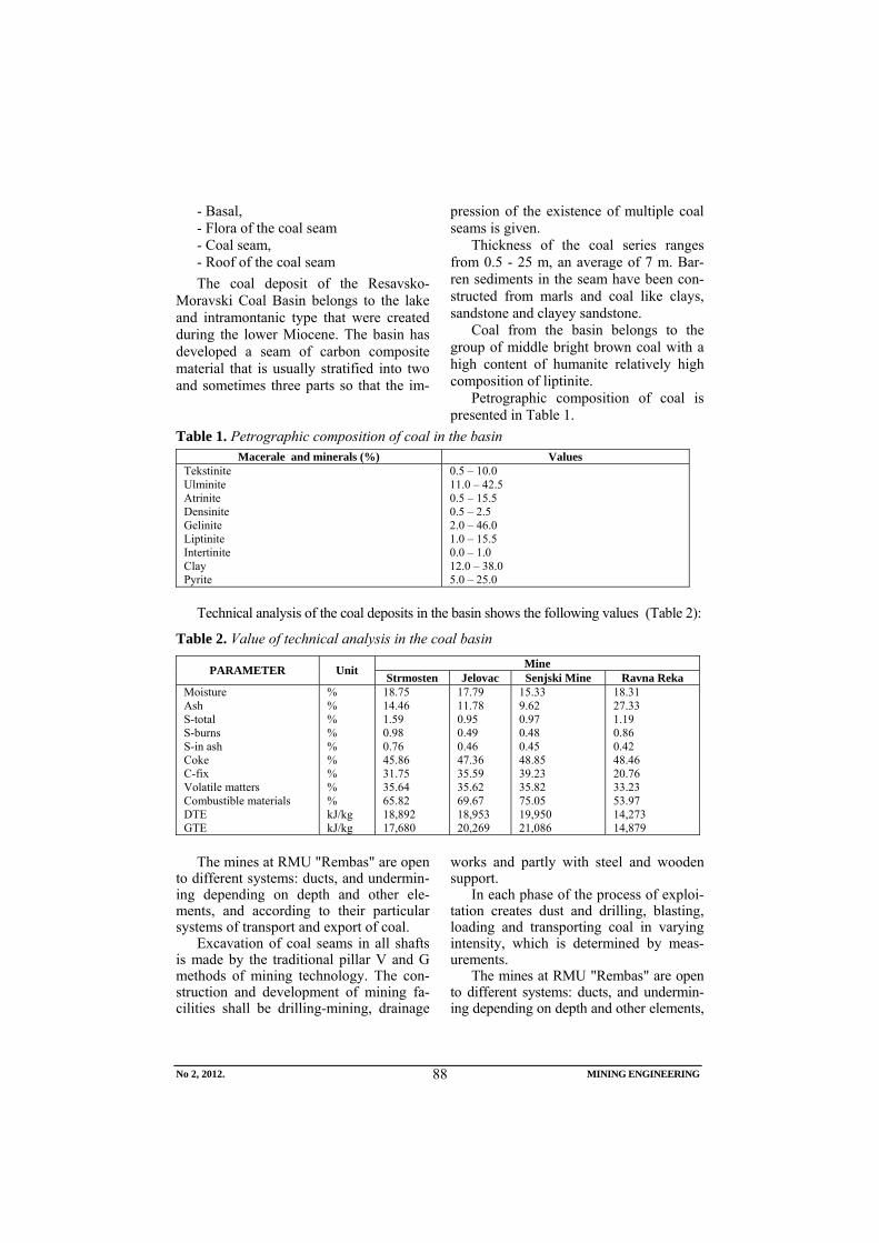
No 2, 2012. MINING ENGINEERING
88
- Basal, - Flora of the coal seam - Coal seam, - Roof of the coal seam The coal deposit of the Resavsko-
Moravski Coal Basin belongs to the lake and intramontanic type that were created during the lower Miocene. The basin has developed a seam of carbon composite material that is usually stratified into two and sometimes three parts so that the im-
pression of the existence of multiple coal seams is given.
Thickness of the coal series ranges from 0.5 - 25 m, an average of 7 m. Bar-ren sediments in the seam have been con-structed from marls and coal like clays, sandstone and clayey sandstone.
Coal from the basin belongs to the group of middle bright brown coal with a high content of humanite relatively high composition of liptinite.
Petrographic composition of coal is presented in Table 1.
Table 1. Petrographic composition of coal in the basin Macerale and minerals (%) Values
Tekstinite Ulminite Atrinite Densinite Gelinite Liptinite Intertinite Clay Pyrite
0.5 – 10.0 11.0 – 42.5 0.5 – 15.5 0.5 – 2.5 2.0 – 46.0 1.0 – 15.5 0.0 – 1.0 12.0 – 38.0 5.0 – 25.0
Technical analysis of the coal deposits in the basin shows the following values (Table 2):
Table 2. Value of technical analysis in the coal basin Mine PARAMETER Unit Strmosten Jelovac Senjski Mine Ravna Reka
Moisture Ash S-total S-burns S-in ash Coke C-fix Volatile matters Combustible materials DTE GTE
% % % % % % % % % kJ/kg kJ/kg
18.75 14.46 1.59 0.98 0.76 45.86 31.75 35.64 65.82 18,892 17,680
17.79 11.78 0.95 0.49 0.46 47.36 35.59 35.62 69.67 18,953 20,269
15.33 9.62 0.97 0.48 0.45 48.85 39.23 35.82 75.05 19,950 21,086
18.31 27.33 1.19 0.86 0.42 48.46 20.76 33.23 53.97 14,273 14,879
The mines at RMU "Rembas" are open
to different systems: ducts, and undermin-ing depending on depth and other ele-ments, and according to their particular systems of transport and export of coal.
Excavation of coal seams in all shafts is made by the traditional pillar V and G methods of mining technology. The con-struction and development of mining fa-cilities shall be drilling-mining, drainage
works and partly with steel and wooden support.
In each phase of the process of exploi-tation creates dust and drilling, blasting, loading and transporting coal in varying intensity, which is determined by meas-urements.
The mines at RMU "Rembas" are open to different systems: ducts, and undermin-ing depending on depth and other elements,
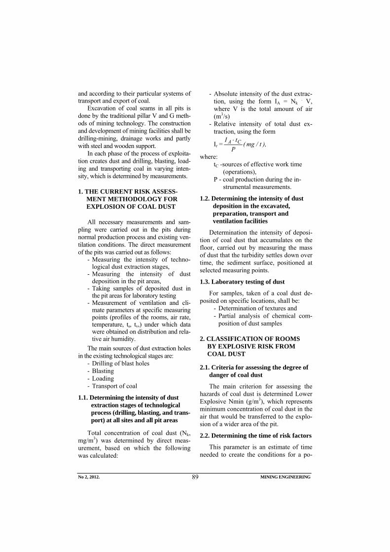
No 2, 2012. MINING ENGINEERING
89
and according to their particular systems of transport and export of coal.
Excavation of coal seams in all pits is done by the traditional pillar V and G meth-ods of mining technology. The construction and development of mining facilities shall be drilling-mining, drainage works and partly with steel and wooden support.
In each phase of the process of exploita-tion creates dust and drilling, blasting, load-ing and transporting coal in varying inten-sity, which is determined by measurements.
1. THE CURRENT RISK ASSESS-MENT METHODOLOGY FOR EXPLOSION OF COAL DUST
All necessary measurements and sam-pling were carried out in the pits during normal production process and existing ven-tilation conditions. The direct measurement of the pits was carried out as follows:
- Measuring the intensity of techno-logical dust extraction stages,
- Measuring the intensity of dust deposition in the pit areas,
- Taking samples of deposited dust in the pit areas for laboratory testing
- Measurement of ventilation and cli-mate parameters at specific measuring points (profiles of the rooms, air rate, temperature, ts, tv,) under which data were obtained on distribution and rela-tive air humidity.
The main sources of dust extraction holes in the existing technological stages are:
- Drilling of blast holes - Blasting - Loading - Transport of coal
1.1. Determining the intensity of dust extraction stages of technological process (drilling, blasting, and trans-port) at all sites and all pit areas
Total concentration of coal dust (Nk, mg/m3) was determined by direct meas-urement, based on which the following was calculated:
- Absolute intensity of the dust extrac-tion, using the form IA = Nk . V, where V is the total amount of air (m3/s)
- Relative intensity of total dust ex-traction, using the form
Ir = ),t/mg(P
tI CA ⋅
where: tC -sources of effective work time
(operations), P - coal production during the in-
strumental measurements.
1.2. Determining the intensity of dust deposition in the excavated, preparation, transport and ventilation facilities
Determination the intensity of deposi-tion of coal dust that accumulates on the floor, carried out by measuring the mass of dust that the turbidity settles down over time, the sediment surface, positioned at selected measuring points.
1.3. Laboratory testing of dust
For samples, taken of a coal dust de-posited on specific locations, shall be:
- Determination of textures and - Partial analysis of chemical com-
position of dust samples
2. CLASSIFICATION OF ROOMS BY EXPLOSIVE RISK FROM COAL DUST
2.1. Criteria for assessing the degree of danger of coal dust
The main criterion for assessing the hazards of coal dust is determined Lower Explosive Nmin (g/m3), which represents minimum concentration of coal dust in the air that would be transferred to the explo-sion of a wider area of the pit.
2.2. Determining the time of risk factors
This parameter is an estimate of time needed to create the conditions for a po-
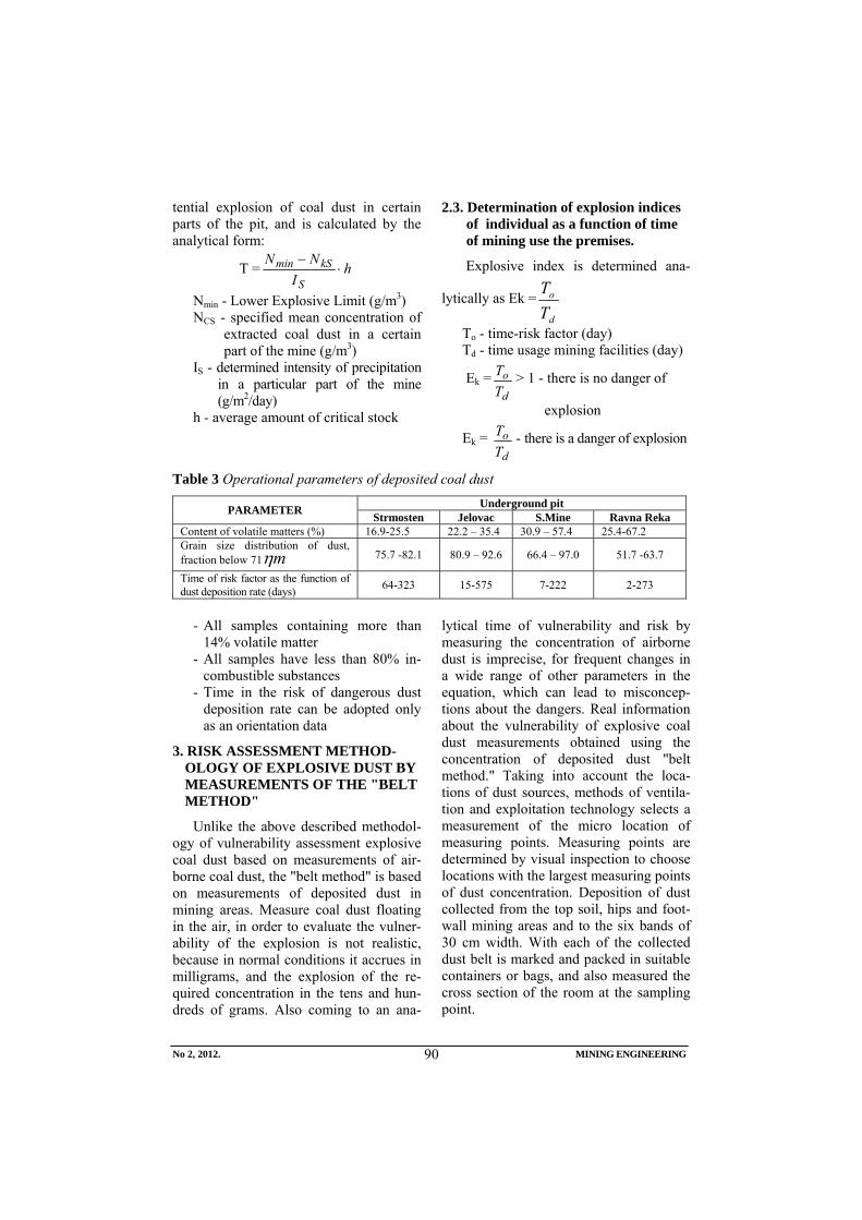
No 2, 2012. MINING ENGINEERING
90
tential explosion of coal dust in certain parts of the pit, and is calculated by the analytical form:
T = hI
NN
S
kSmin ⋅−
Nmin - Lower Explosive Limit (g/m3) NCS - specified mean concentration of
extracted coal dust in a certain part of the mine (g/m3)
IS - determined intensity of precipitation in a particular part of the mine (g/m2/day)
h - average amount of critical stock
2.3. Determination of explosion indices of individual as a function of time of mining use the premises.
Explosive index is determined ana-
lytically as Ek =d
o
TT
To - time-risk factor (day) Td - time usage mining facilities (day)
Ek =d
oTT > 1 - there is no danger of
explosion
Ek = d
oTT - there is a danger of explosion
Table 3 Operational parameters of deposited coal dust Underground pit PARAMETER Strmosten Jelovac S.Mine Ravna Reka
Content of volatile matters (%) 16.9-25.5 22.2 – 35.4 30.9 – 57.4 25.4-67.2 Grain size distribution of dust, fraction below 71 mη 75.7 -82.1 80.9 – 92.6 66.4 – 97.0 51.7 -63.7
Time of risk factor as the function of dust deposition rate (days) 64-323 15-575 7-222 2-273
- All samples containing more than
14% volatile matter - All samples have less than 80% in-
combustible substances - Time in the risk of dangerous dust
deposition rate can be adopted only as an orientation data
3. RISK ASSESSMENT METHOD-OLOGY OF EXPLOSIVE DUST BY MEASUREMENTS OF THE "BELT METHOD"
Unlike the above described methodol-ogy of vulnerability assessment explosive coal dust based on measurements of air-borne coal dust, the "belt method" is based on measurements of deposited dust in mining areas. Measure coal dust floating in the air, in order to evaluate the vulner-ability of the explosion is not realistic, because in normal conditions it accrues in milligrams, and the explosion of the re-quired concentration in the tens and hun-dreds of grams. Also coming to an ana-
lytical time of vulnerability and risk by measuring the concentration of airborne dust is imprecise, for frequent changes in a wide range of other parameters in the equation, which can lead to misconcep-tions about the dangers. Real information about the vulnerability of explosive coal dust measurements obtained using the concentration of deposited dust "belt method." Taking into account the loca-tions of dust sources, methods of ventila-tion and exploitation technology selects a measurement of the micro location of measuring points. Measuring points are determined by visual inspection to choose locations with the largest measuring points of dust concentration. Deposition of dust collected from the top soil, hips and foot-wall mining areas and to the six bands of 30 cm width. With each of the collected dust belt is marked and packed in suitable containers or bags, and also measured the cross section of the room at the sampling point.
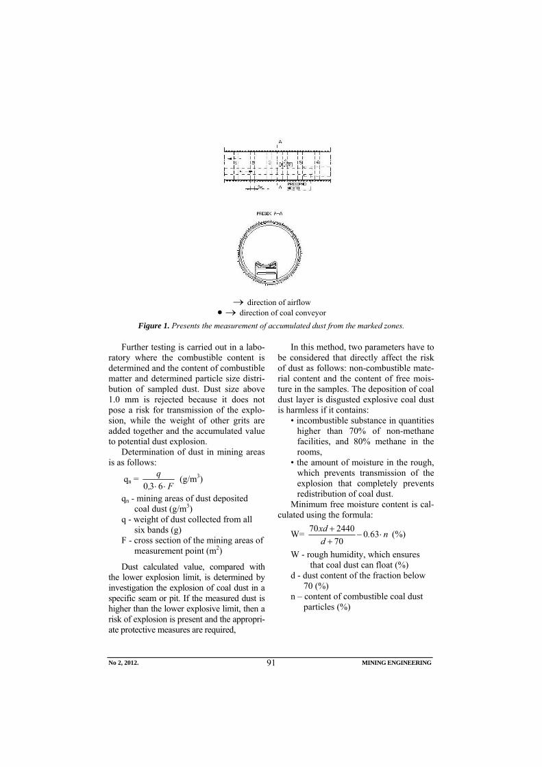
No 2, 2012. MINING ENGINEERING
91
→ direction of airflow
→• direction of coal conveyor Figure 1. Presents the measurement of accumulated dust from the marked zones.
Further testing is carried out in a labo-
ratory where the combustible content is determined and the content of combustible matter and determined particle size distri-bution of sampled dust. Dust size above 1.0 mm is rejected because it does not pose a risk for transmission of the explo-sion, while the weight of other grits are added together and the accumulated value to potential dust explosion.
Determination of dust in mining areas is as follows:
qn = F,
q⋅⋅630
(g/m3)
qn - mining areas of dust deposited coal dust (g/m3)
q - weight of dust collected from all six bands (g)
F - cross section of the mining areas of measurement point (m2)
Dust calculated value, compared with the lower explosion limit, is determined by investigation the explosion of coal dust in a specific seam or pit. If the measured dust is higher than the lower explosive limit, then a risk of explosion is present and the appropri-ate protective measures are required,
In this method, two parameters have to be considered that directly affect the risk of dust as follows: non-combustible mate-rial content and the content of free mois-ture in the samples. The deposition of coal dust layer is disgusted explosive coal dust is harmless if it contains:
• incombustible substance in quantities higher than 70% of non-methane facilities, and 80% methane in the rooms,
• the amount of moisture in the rough, which prevents transmission of the explosion that completely prevents redistribution of coal dust.
Minimum free moisture content is cal-culated using the formula:
W= n.dxd
⋅−++ 63070244070 (%)
W - rough humidity, which ensures that coal dust can float (%)
d - dust content of the fraction below 70 (%)
n – content of combustible coal dust particles (%)
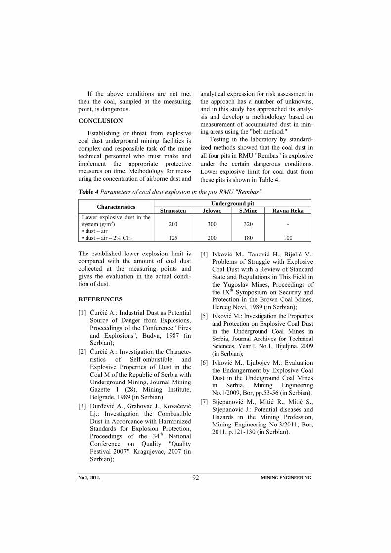
No 2, 2012. MINING ENGINEERING
92
If the above conditions are not met then the coal, sampled at the measuring point, is dangerous.
CONCLUSION
Establishing or threat from explosive coal dust underground mining facilities is complex and responsible task of the mine technical personnel who must make and implement the appropriate protective measures on time. Methodology for meas-uring the concentration of airborne dust and
analytical expression for risk assessment in the approach has a number of unknowns, and in this study has approached its analy-sis and develop a methodology based on measurement of accumulated dust in min-ing areas using the "belt method."
Testing in the laboratory by standard-ized methods showed that the coal dust in all four pits in RMU "Rembas" is explosive under the certain dangerous conditions. Lower explosive limit for coal dust from these pits is shown in Table 4.
Table 4 Parameters of coal dust explosion in the pits RMU "Rembas"
Underground pit Characteristics Strmosten Jelovac S.Mine Ravna Reka Lower explosive dust in the system (g/m3) • dust – air • dust – air – 2% CH4
200
125
300
200
320
180
-
100
The established lower explosion limit is compared with the amount of coal dust collected at the measuring points and gives the evaluation in the actual condi-tion of dust.
REFERENCES
[1] Ćurčić A.: Industrial Dust as Potential Source of Danger from Explosions, Proceedings of the Conference "Fires and Explosions", Budva, 1987 (in Serbian);
[2] Ćurčić A.: Investigation the Characte-ristics of Self-ombustible and Explosive Properties of Dust in the Coal M of the Republic of Serbia with Underground Mining, Journal Mining Gazette 1 (28), Mining Institute, Belgrade, 1989 (in Serbian)
[3] Đurđević A., Grahovac J., Kovačević Lj.: Investigation the Combustible Dust in Accordance with Harmonized Standards for Explosion Protection, Proceedings of the 34th National Conference on Quality "Quality Festival 2007", Kragujevac, 2007 (in Serbian);
[4] Ivković M., Tanović H., Bijelić V.: Problems of Struggle with Explosive Coal Dust with a Review of Standard State and Regulations in This Field in the Yugoslav Mines, Proceedings of the IXth Symposium on Security and Protection in the Brown Coal Mines, Herceg Novi, 1989 (in Serbian);
[5] Ivković M.: Investigation the Properties and Protection on Explosive Coal Dust in the Underground Coal Mines in Serbia, Journal Archives for Technical Sciences, Year I, No.1, Bijeljina, 2009 (in Serbian);
[6] Ivković M., Ljubojev M.: Evaluation the Endangerment by Explosive Coal Dust in the Underground Coal Mines in Serbia, Mining Engineering No.1/2009, Bor, pp.53-56 (in Serbian).
[7] Stjepanović M., Mitić R., Mitić S., Stjepanović J.: Potential diseases and Hazards in the Mining Profession, Mining Engineering No.3/2011, Bor, 2011, p.121-130 (in Serbian).
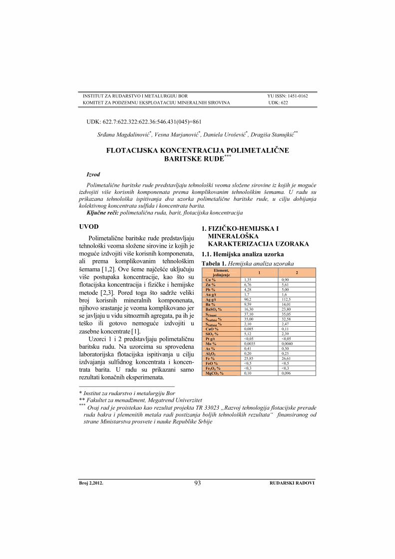
Broj 2,2012. RUDARSKI RADOVI
93
INSTITUT ZA RUDARSTVO I METALURGIJU BOR YU ISSN: 1451-0162 KOMITET ZA PODZEMNU EKSPLOATACIJU MINERALNIH SIROVINA UDK: 622
UDK: 622.7:622.322:622.36:546.431(045)=861
Srđana Magdalinović*, Vesna Marjanović*, Daniela Urošević*, Dragiša Stanujkić**
FLOTACIJSKA KONCENTRACIJA POLIMETALIČNE BARITSKE RUDE***
Izvod
Polimetalične baritske rude predstavljaju tehnološki veoma složene sirovine iz kojih je moguće izdvojiti više korisnih komponenata prema komplikovanim tehnološkim šemama. U radu su prikazana tehnološka ispitivanja dva uzorka polimetalične baritske rude, u cilju dobijanja kolektivnog koncentrata sulfida i koncentrata barita.
Ključne reči: polimetalična ruda, barit, flotacijska koncentracija
* Institut za rudarstvo i metalurgiju Bor ** Fakultet za menadžment, Megatrend Univerzitet *** Ovaj rad je proistekao kao rezultat projekta TR 33023 „Razvoj tehnologija flotacijske prerade
ruda bakra i plemenitih metala radi postizanja boljih tehnoloških rezultata“ finansiranog od strane Ministarstva prosvete i nauke Republike Srbije
UVOD
Polimetalične baritske rude predstavljaju tehnološki veoma složene sirovine iz kojih je moguće izdvojiti više korisnih komponenata, ali prema komplikovanim tehnološkim šemama [1,2]. Ove šeme najčešće uključuju više postupaka koncentracije, kao što su flotacijska koncentracija i fizičke i hemijske metode [2,3]. Pored toga što sadrže veliki broj korisnih mineralnih komponenata, njihovo srastanje je veoma komplikovano jer se javljaju u vidu sitnozrnih agregata, pa ih je teško ili gotovo nemoguće izdvojiti u zasebne koncentrate [1].
Uzorci 1 i 2 predstavljaju polimetaličnu baritsku rudu. Na uzorcima su sprovedena laboratorijska flotacijska ispitivanja u cilju izdvajanja sulfidnog koncentrata i koncen-trata barita. U radu su prikazani samo rezultati konačnih eksperimenata.
1. FIZIČKO-HEMIJSKA I MINERALOŠKA KARAKTERIZACIJA UZORAKA
1.1. Hemijska analiza uzorka Tabela 1. Hemijska analiza uzoraka
Element, jedinjenje 1 2
Cu % 1,35 0,90 Zn % 6,76 5,61 Pb % 4,28 5,00 Au g/t 1,7 1,6 Ag g/t 90,2 112,5 Ba % 9,59 14,01 BaSO4 % 16,30 23,80 SUkupni 37,10 35,05 SSulfidni % 35,00 32,58 SSulfatni % 2,10 2,47 CaO % 0,085 0,11 SiO2 % 5,12 2,39 Pt g/t <0,05 <0,05 Mo % 0,0035 0,0040 As % 0,41 0,30 Al2O3 0,20 0,23 Fe % 25,85 26,61 FeO % <0,5 <0,5 Fe3O4 % <0,3 <0,3 MgCO3 % 0,10 0,096
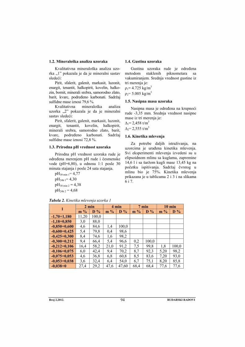
Broj 2,2012. RUDARSKI RADOVI
94
1.2. Mineraloška analiza uzoraka
Kvalitativna mineraloška analiza uzo-rka „1” pokazala je da je mineralni sastav sledeći:
Pirit, sfalerit, galenit, markasit, luzonit, enargit, tenantit, halkopirit, kovelin, halko-zin, bornit, minerali srebra, samorodno zlato, barit, kvarc, podređeno karbonati. Sadržaj sulfidne mase iznosi 79,6 %.
Kvalitativna mineraloška analiza uzorka „2” pokazala je da je mineralni sastav sledeći:
Pirit, sfalerit, galenit, markasit, luzonit, enargit, tenantit, kovelin, halkopirit, minerali srebra, samorodno zlato, barit, kvarc, podređeno karbonati. Sadržaj sulfidne mase iznosi 72,8 %.
1.3. Prirodna pH vrednost uzoraka
Prirodna pH vrednost uzoraka rude je određena merenjem pH rude i česmenske vode (pH=6,80), u odnosu 1:1 posle 30 minuta stajanja i posle 24 sata stajanja.
pH30 min 1= 4,77 pH24h 1= 4,30 pH30 min 2 = 4,38 pH24h 2 = 4,68
1.4. Gustina uzoraka
Gustina uzoraka rude je određena metodom staklenih piknometara sa vakumiranjem. Srednja vrednost gustine iz tri merenja je: ρ1= 4.725 kg/m3 ρ2= 5.005 kg/m3
1.5. Nasipna masa uzoraka
Nasipna masa je određena na krupnoći rude -3,35 mm. Srednja vrednost nasipne mase iz tri merenja je: ∆1= 2,458 t/m3 ∆2= 2,555 t/m3
1.6. Kinetika mlevenja
Za potrebe daljih istraživanja, na uzorcima je urađena kinetika mlevenja. Svi eksperimenti mlevenja izvedeni su u elipsoidnom mlinu sa kuglama, zapremine 14,6 l i sa šaržom kugli mase 13,45 kg na početku ispitivanja. Sadržaj čvrstog u mlinu bio je 75%. Kinetika mlevenja prikazana je u tablicama 2 i 3 i na slikama 6 i 7.
Tabela 2. Kinetika mlevenja uzorka 1 2 min 4 min 7 min 10 min 1 m % D % m % D % m % D % m % D %
-1,70+1,180 11,20 100,0 -1,18+0,850 3,0 88,0 -0,850+0,600 4,6 84,6 1,4 100,0 -0,600+0,425 5,4 79,8 0,4 98,6 -0,425+0,300 8,4 74,6 1,6 98,2 -0,300+0,212 9,4 66,4 5,4 96,6 0,2 100,0 -0,212+0,106 16,4 58,2 21,0 91,2 7,5 99,8 1,8 100,0 -0,106+0,075 6,0 42,4 9,4 70,2 8,7 92,3 5,20 98,2 -0,075+0,053 4,6 36,8 6,8 60,8 8,5 83,6 7,20 93,0 -0,053+0,038 3,6 32,4 6,4 54,0 6,7 75,1 8,20 85,8 -0,038+0 27,4 29,2 47,6 47,60 68,4 68,4 77,6 77,6
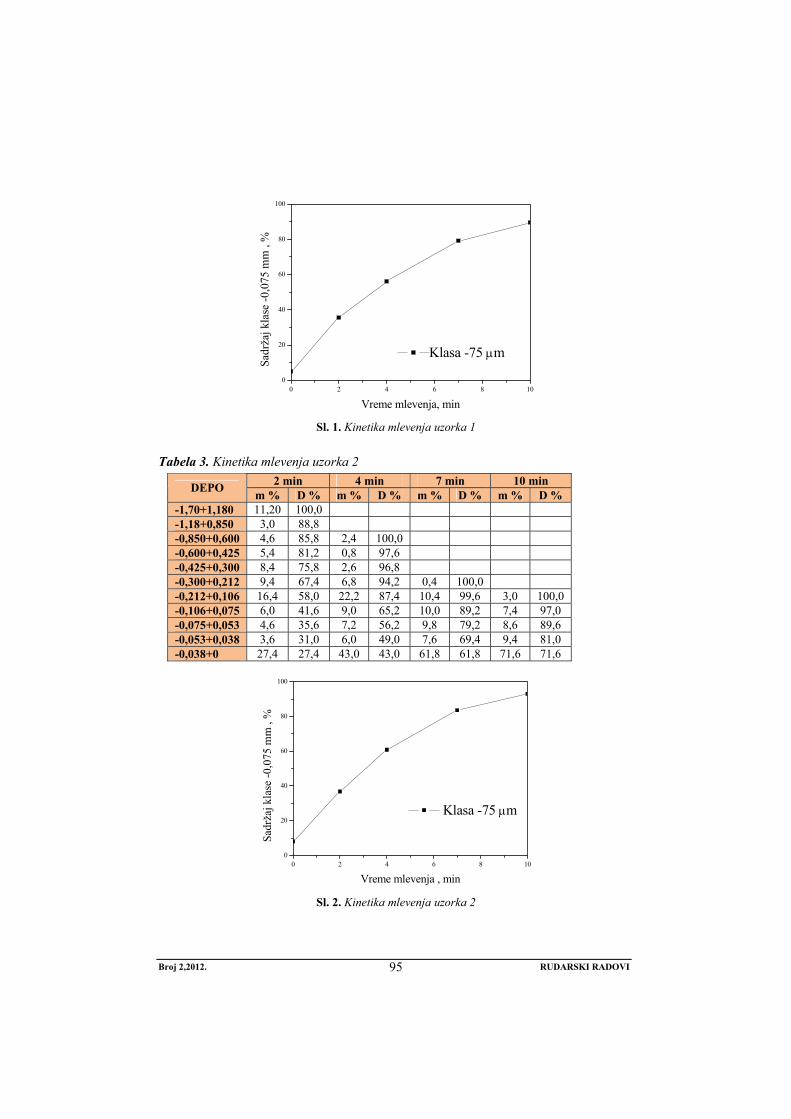
Broj 2,2012. RUDARSKI RADOVI
95
0 2 4 6 8 100
20
40
60
80
100
Klasa -75 μm
Sadr
žaj k
lase
-0,0
75 m
m ,
%
Vreme mlevenja, min Sl. 1. Kinetika mlevenja uzorka 1
Tabela 3. Kinetika mlevenja uzorka 2 2 min 4 min 7 min 10 min DEPO m % D % m % D % m % D % m % D %
-1,70+1,180 11,20 100,0 -1,18+0,850 3,0 88,8 -0,850+0,600 4,6 85,8 2,4 100,0 -0,600+0,425 5,4 81,2 0,8 97,6 -0,425+0,300 8,4 75,8 2,6 96,8 -0,300+0,212 9,4 67,4 6,8 94,2 0,4 100,0 -0,212+0,106 16,4 58,0 22,2 87,4 10,4 99,6 3,0 100,0 -0,106+0,075 6,0 41,6 9,0 65,2 10,0 89,2 7,4 97,0 -0,075+0,053 4,6 35,6 7,2 56,2 9,8 79,2 8,6 89,6 -0,053+0,038 3,6 31,0 6,0 49,0 7,6 69,4 9,4 81,0 -0,038+0 27,4 27,4 43,0 43,0 61,8 61,8 71,6 71,6
0 2 4 6 8 100
20
40
60
80
100
Klasa -75 μm
Sadr
žaj k
lase
-0,0
75 m
m ,
%
Vreme mlevenja , min Sl. 2. Kinetika mlevenja uzorka 2
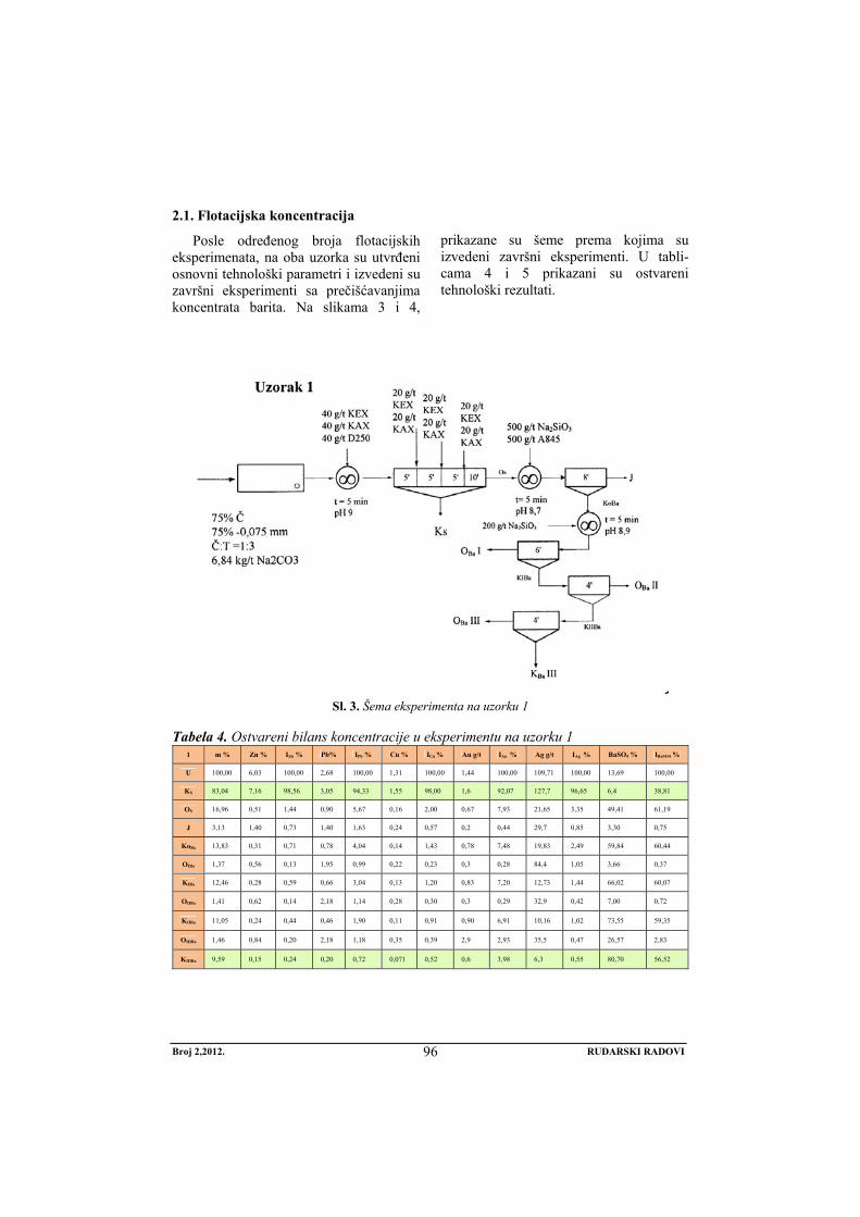
Broj 2,2012. RUDARSKI RADOVI
96
2.1. Flotacijska koncentracija
Posle određenog broja flotacijskih eksperimenata, na oba uzorka su utvrđeni osnovni tehnološki parametri i izvedeni su završni eksperimenti sa prečišćavanjima koncentrata barita. Na slikama 3 i 4,
prikazane su šeme prema kojima su izvedeni završni eksperimenti. U tabli-cama 4 i 5 prikazani su ostvareni tehnološki rezultati.
Sl. 3. Šema eksperimenta na uzorku 1
Tabela 4. Ostvareni bilans koncentracije u eksperimentu na uzorku 1
1 m % Zn % IZn % Pb% IPb % Cu % ICu % Au g/t IAu % Ag g/t IAg % BaSO4 % IBaSO4 %
U 100,00 6,03 100,00 2,68 100,00 1,31 100,00 1,44 100,00 109,71 100,00 13,69 100,00
KS 83,04 7,16 98,56 3,05 94,33 1,55 98,00 1,6 92,07 127,7 96,65 6,4 38,81
OS 16,96 0,51 1,44 0,90 5,67 0,16 2,00 0,67 7,93 21,65 3,35 49,41 61,19
J 3,13 1,40 0,73 1,40 1,63 0,24 0,57 0,2 0,44 29,7 0,85 3,30 0,75
KoBa 13,83 0,31 0,71 0,78 4,04 0,14 1,43 0,78 7,48 19,83 2,49 59,84 60,44
OIBa 1,37 0,56 0,13 1,95 0,99 0,22 0,23 0,3 0,28 84,4 1,05 3,66 0,37
KIBa 12,46 0,28 0,59 0,66 3,04 0,13 1,20 0,83 7,20 12,73 1,44 66,02 60,07
OIIBa 1,41 0,62 0,14 2,18 1,14 0,28 0,30 0,3 0,29 32,9 0,42 7,00 0,72
KIIBa 11,05 0,24 0,44 0,46 1,90 0,11 0,91 0,90 6,91 10,16 1,02 73,55 59,35
OIIIBa 1,46 0,84 0,20 2,18 1,18 0,35 0,39 2,9 2,93 35,5 0,47 26,57 2,83
KIIIBa 9,59 0,15 0,24 0,20 0,72 0,071 0,52 0,6 3,98 6,3 0,55 80,70 56,52
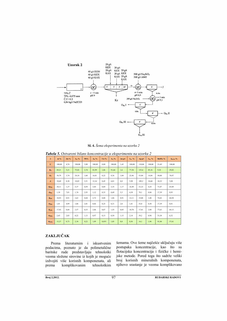
Broj 2,2012. RUDARSKI RADOVI
97
Sl. 4. Šema eksperimenta na uzorku 2
Tabela 5. Ostvareni bilans koncentracije u eksperimentu na uzorku 2
ZAKLJUČAK
Prema literaturnim i iskustvenim podacima, poznato je da polimetalične baritske rude predstavljaju tehnološki veoma složene sirovine iz kojih je moguće izdvojiti više korisnih komponenata, ali prema komplikovanim tehnološkim
šemama. Ove šeme najčešće uključuju više postupaka koncentracije, kao što su flotacijska koncentracija i fizičke i hemi-jske metode. Pored toga što sadrže veliki broj korisnih mineralnih komponenata, njihovo srastanje je veoma komplikovano
2 m % Zn % IZn % Pb% IPb % Cu % ICu % Au g/t IAu % Ag g/t IAg % BaSO4 % IBaSO4 %
U 100,00 4,76 100,00 3,08 100,00 0,80 100,00 1,43 100,00 110,04 100,00 21,69 100,00
KS 69,21 5,21 75,82 3,74 83,99 1,06 91,64 1,6 77,54 135,4 85,16 9,10 29,03
OS 30,79 3,74 24,18 1,60 16,01 0,22 8,36 1,04 22,46 53,04 14,84 50,00 70,97
J 10,68 8,38 18,82 3,51 12,16 0,45 6,01 0,8 5,98 109,2 10,60 10,32 5,08
KoBa 20,11 1,27 5,37 0,59 3,84 0,09 2,35 1,17 16,49 23,22 4,24 71,07 65,89
OIBa 1,18 7,01 1,74 2,93 1,12 0,33 0,49 5,3 4,38 78,1 0,84 17,39 0,95
KIBa 18,93 0,91 3,63 0,44 2,72 0,08 1,86 0,91 12,11 19,80 3,40 74,42 64,94
OIIBa 1,01 4,99 1,06 2,01 0,66 0,25 0,31 2,0 1,41 55,0 0,50 17,39 0,81
KIIBa 17,92 0,68 2,57 0,35 2,06 0,07 1,55 0,85 10,70 17,81 2,90 77,63 64,13
OIIIBa 2,65 2,03 0,22 1,13 0,97 0,15 0,50 1,15 2,14 39,2 0,94 53,38 6,52
KIIIBa 15,27 0,73 2,34 0,22 1,09 0,055 1,05 0,8 8,56 14,1 1,96 81,84 57,61
Broj 2,2012. RUDARSKI RADOVI
98
jer se javljaju se u vidu sitnozrnih agregata, pa ih je teško ili gotovo nemoguće izdvojiti u zasebne koncentrate.
Uzorci 1 i 2 predstavljaju polimetaličnu baritsku rudu. Uzorak 1 sadrži: 1,35%Cu, 6,76 % Zn, 4,28 % Pb, 1,7 g/t Au, 90,2 g/t Ag, 9,59 % Ba i 16,30 % BaSO4. Uzorak 2 sadrži 0,90 % Cu, 5,61 % Zn, 5,00 % Pb, 1,6 g/t Au, 112,5 g/t Ag, 11,01 % Ba i 23,80 % BaSO4. Na osnovu sprovedenih eksperimenata flotacijske koncentracije doneti su sledeći zaključci:
- Oba uzorka su tehnološki vrlo slična tako da ruda koju predstavljaju može da se prerađuje prema istim šemama.
- U uzorcima je sulfidna masa dominantna, što je pokazala i miner-loška analiza. To se odrazilo na masu sulfidnog koncentrata koja je varirala uglavnom od 75-80% u odnosu na ulaz u flotaciju.
- Velika količina sulfidnog kon-centrata značajno se odrazila na nisku koncentraciju korisnih metala
- Sadržaj barita u otoku flotacije sulfida je nizak pa ga je neophodno koncentrisati flotiranjem.
- Sa tri prečišćavanja koncentrata barita, dobijen je sadržaj BaSO4 od 80% što je niže nego što su zahtevi za upotrebu. Dva do tri dodatna prečišćavanja koncentrata bi dovela do kvaliteta koncentrata odgo-varajuće tržišne vrednosti.
Optimizacijom tehnoloških parametara verovatno bi mogli da se dobiju nešto bolji rezultati u koncentraciji barita.
Konačno, na osnovu sprovedenih ispitivanja može da se zaključi da uzorci 1 i 2 predstavljaju komplikovanu sirovinu, masivno sulfidnu sa velikim sadržajem bakra, cinka, olova, srebra, zlata i barita. Tako komplikovana sirovina, zahteva detaljna laboratorijska ispitivanja sa ciljem utvrđivanja tehnologije za najoptimalniju valorizaciju svih korisnih mineralnih komponenata.
LITERATURA
[1] Handbook of Flotation reagent: Chemistry, Theory and Practice: Flotation of Sulfide Ores, Srdjan M. Bulatović, ISBN: 0444530290, Publisher: Elsevier Science & Technology Books, 2007.
[2] Priprema nemetaličnih mineralnih sirovina, J. Pavlica, D. Dračkić, ISBN 86-7352-012-6, RGF Beograd, 1997.
[3] Domaće nemetalične mineralne sirovine za primenu u privredi, Grupa autora, ISBN 86-82867-09-5, ITNMS, Beograd 1998.
[4] Mining Chemical Handbook, Cytec, 2010.
No 2, 2012. MINING ENGINEERING
99
MINING AND METALLURGY INSTITUTE BOR YU ISSN: 1451-0162 COMMITTEE OF UNDERGROUND EXPLOITATION OF THE MINERAL DEPOSITS UDK: 622
UDK: 622.7:622.33:622.36:546.431(045)=20
Srđana Magdalinović*, Vesna Marjanović*, Daniela Urošević*, Dragiša Stanujkić**
FLOTATION CONCENTRATION OF POLYMETALLIC BARITE ORE***
Abstract
The polymetallic barite ore is technologically very complex raw material from which is possi-ble to extract more useful components using the complex technological schemes. This paper pre-sents the technological testing of two samples the polymetallic barite ore, in order to obtain a collective concentrate of sulphides and barite concentrate.
Keywords: polymetallic ore, barite, flotation concentration
* Mining and Metallurgy Institute Bor ** Faculty of Management in Zaječar, University Megatrend Belgrade *** This work has resulted from the TR Project: 33023, entitled "Technology Development of Flo-
tation Processing of Copper Ore and Precious Metals in Order to Achieve Better Technological Results" for which we would like to thank to the Ministry of Education and Science of the Repub-lic of Serbia for funding.
INTRODUCTION
The polymetallic barite ore is techno-logically very complex raw material from which is possible to extract more useful components but using the complex tech-nological schemes [1, 2]. These schemes usually involve multiple processes of con-centration, such as the flotation concentra-tion and physical and chemical methods [2, 3]. In addition to the content a number of useful mineral components, their inter-growth is very complicated, because they
appear in the form of fine grained aggre-gates, so it is difficult or almost impossi-ble to separate them into separate concen-trates [1]. Samples 1 and 2 represent the polymetallic barite ore. Were conducted on samples of The laboratory flotation tests f were carried out on samples in or-der to separate the sulphide concentrate and barite concentrate. This paper presents only the results of final experiments.
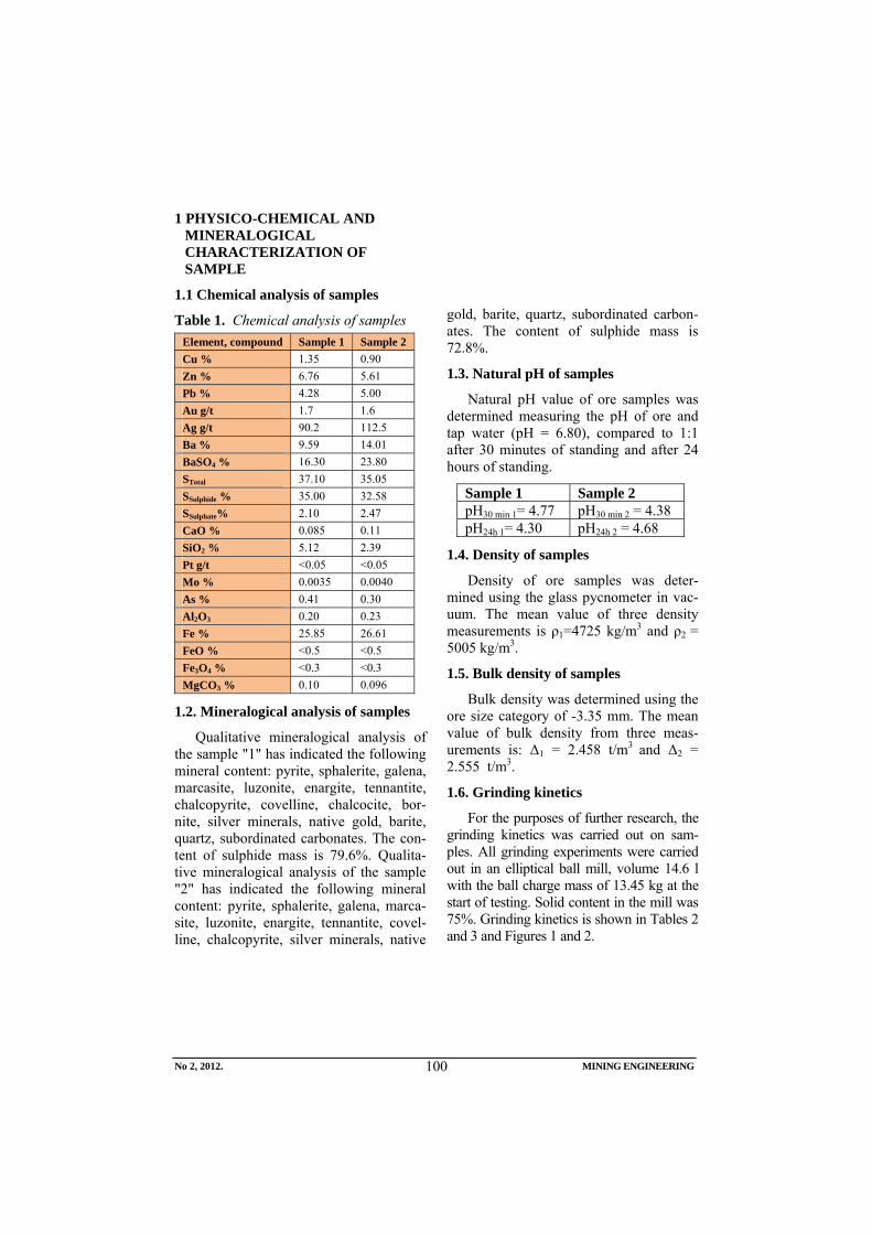
No 2, 2012. MINING ENGINEERING
100
1 PHYSICO-CHEMICAL AND MINERALOGICAL CHARACTERIZATION OF SAMPLE
1.1 Chemical analysis of samples
Table 1. Chemical analysis of samples Element, compound Sample 1 Sample 2 Cu % 1.35 0.90 Zn % 6.76 5.61 Pb % 4.28 5.00 Au g/t 1.7 1.6 Ag g/t 90.2 112.5 Ba % 9.59 14.01 BaSO4 % 16.30 23.80 STotal 37.10 35.05 SSulphide % 35.00 32.58 SSulphate% 2.10 2.47 CaO % 0.085 0.11 SiO2 % 5.12 2.39 Pt g/t <0.05 <0.05 Mo % 0.0035 0.0040 As % 0.41 0.30 Al2O3 0.20 0.23 Fe % 25.85 26.61 FeO % <0.5 <0.5 Fe3O4 % <0.3 <0.3 MgCO3 % 0.10 0.096
1.2. Mineralogical analysis of samples
Qualitative mineralogical analysis of the sample "1" has indicated the following mineral content: pyrite, sphalerite, galena, marcasite, luzonite, enargite, tennantite, chalcopyrite, covelline, chalcocite, bor-nite, silver minerals, native gold, barite, quartz, subordinated carbonates. The con-tent of sulphide mass is 79.6%. Qualita-tive mineralogical analysis of the sample "2" has indicated the following mineral content: pyrite, sphalerite, galena, marca-site, luzonite, enargite, tennantite, covel-line, chalcopyrite, silver minerals, native
gold, barite, quartz, subordinated carbon-ates. The content of sulphide mass is 72.8%.
1.3. Natural pH of samples
Natural pH value of ore samples was determined measuring the pH of ore and tap water (pH = 6.80), compared to 1:1 after 30 minutes of standing and after 24 hours of standing.
Sample 1 Sample 2 pH30 min 1= 4.77 pH30 min 2 = 4.38 pH24h 1= 4.30 pH24h 2 = 4.68
1.4. Density of samples
Density of ore samples was deter-mined using the glass pycnometer in vac-uum. The mean value of three density measurements is ρ1=4725 kg/m3 and ρ2 = 5005 kg/m3.
1.5. Bulk density of samples
Bulk density was determined using the ore size category of -3.35 mm. The mean value of bulk density from three meas-urements is: Δ1 = 2.458 t/m3 and Δ2 = 2.555 t/m3.
1.6. Grinding kinetics
For the purposes of further research, the grinding kinetics was carried out on sam-ples. All grinding experiments were carried out in an elliptical ball mill, volume 14.6 l with the ball charge mass of 13.45 kg at the start of testing. Solid content in the mill was 75%. Grinding kinetics is shown in Tables 2 and 3 and Figures 1 and 2.
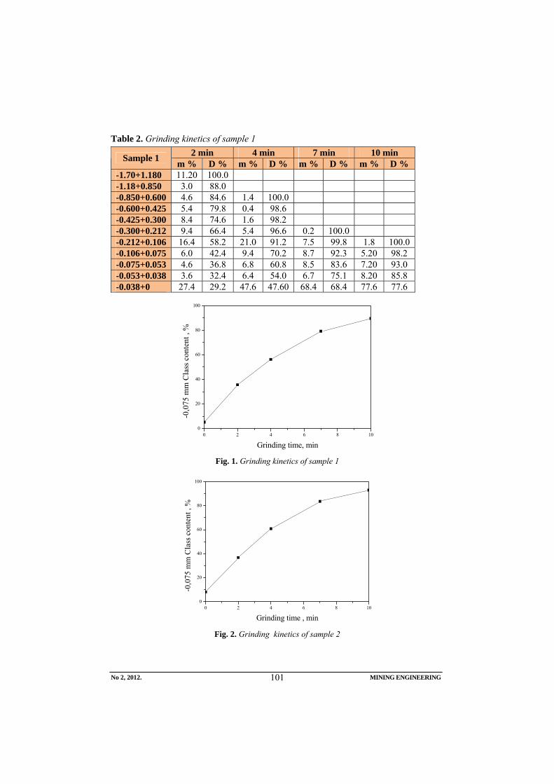
No 2, 2012. MINING ENGINEERING
101
Table 2. Grinding kinetics of sample 1 2 min 4 min 7 min 10 min Sample 1 m % D % m % D % m % D % m % D %
-1.70+1.180 11.20 100.0 -1.18+0.850 3.0 88.0 -0.850+0.600 4.6 84.6 1.4 100.0 -0.600+0.425 5.4 79.8 0.4 98.6 -0.425+0.300 8.4 74.6 1.6 98.2 -0.300+0.212 9.4 66.4 5.4 96.6 0.2 100.0 -0.212+0.106 16.4 58.2 21.0 91.2 7.5 99.8 1.8 100.0 -0.106+0.075 6.0 42.4 9.4 70.2 8.7 92.3 5.20 98.2 -0.075+0.053 4.6 36.8 6.8 60.8 8.5 83.6 7.20 93.0 -0.053+0.038 3.6 32.4 6.4 54.0 6.7 75.1 8.20 85.8 -0.038+0 27.4 29.2 47.6 47.60 68.4 68.4 77.6 77.6
0 2 4 6 8 100
20
40
60
80
100
-0,0
75 m
m C
lass
con
tent
, %
Grinding time, min Fig. 1. Grinding kinetics of sample 1
0 2 4 6 8 100
20
40
60
80
100
-0,0
75 m
m C
lass
con
tent
, %
Grinding time , min Fig. 2. Grinding kinetics of sample 2
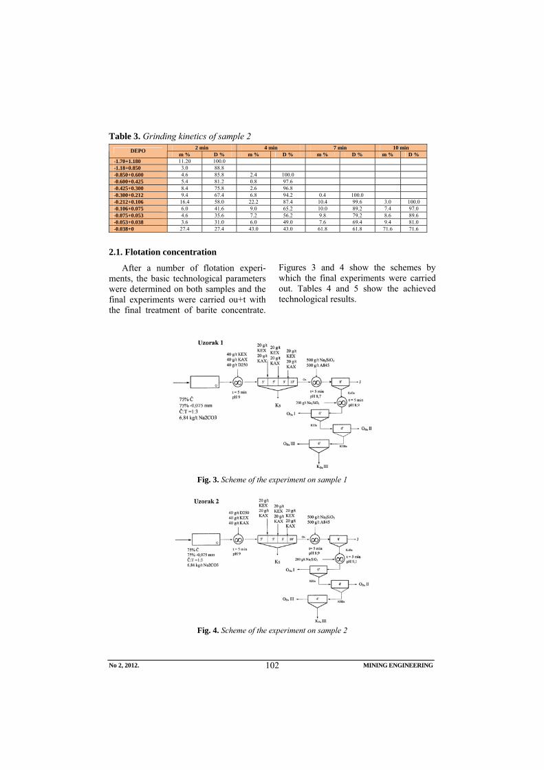
No 2, 2012. MINING ENGINEERING
102
Table 3. Grinding kinetics of sample 2 2 min 4 min 7 min 10 min DEPO
m % D % m % D % m % D % m % D % -1.70+1.180 11.20 100.0 -1.18+0.850 3.0 88.8 -0.850+0.600 4.6 85.8 2.4 100.0 -0.600+0.425 5.4 81.2 0.8 97.6 -0.425+0.300 8.4 75.8 2.6 96.8 -0.300+0.212 9.4 67.4 6.8 94.2 0.4 100.0 -0.212+0.106 16.4 58.0 22.2 87.4 10.4 99.6 3.0 100.0 -0.106+0.075 6.0 41.6 9.0 65.2 10.0 89.2 7.4 97.0 -0.075+0.053 4.6 35.6 7.2 56.2 9.8 79.2 8.6 89.6 -0.053+0.038 3.6 31.0 6.0 49.0 7.6 69.4 9.4 81.0 -0.038+0 27.4 27.4 43.0 43.0 61.8 61.8 71.6 71.6
2.1. Flotation concentration
After a number of flotation experi-ments, the basic technological parameters were determined on both samples and the final experiments were carried ou+t with the final treatment of barite concentrate.
Figures 3 and 4 show the schemes by which the final experiments were carried out. Tables 4 and 5 show the achieved technological results.
Fig. 3. Scheme of the experiment on sample 1
Fig. 4. Scheme of the experiment on sample 2
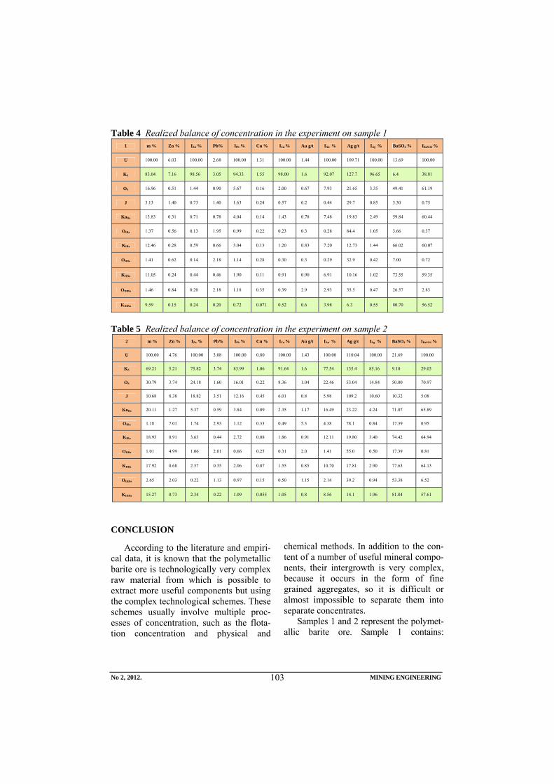
No 2, 2012. MINING ENGINEERING
103
Table 4 Realized balance of concentration in the experiment on sample 1
Table 5 Realized balance of concentration in the experiment on sample 2
CONCLUSION
According to the literature and empiri-cal data, it is known that the polymetallic barite ore is technologically very complex raw material from which is possible to extract more useful components but using the complex technological schemes. These schemes usually involve multiple proc-esses of concentration, such as the flota-tion concentration and physical and
chemical methods. In addition to the con-tent of a number of useful mineral compo-nents, their intergrowth is very complex, because it occurs in the form of fine grained aggregates, so it is difficult or almost impossible to separate them into separate concentrates.
Samples 1 and 2 represent the polymet-allic barite ore. Sample 1 contains:
1 m % Zn % IZn % Pb% IPb % Cu % ICu % Au g/t IAu % Ag g/t IAg % BaSO4 % IBaSO4 %
U 100.00 6.03 100.00 2.68 100.00 1.31 100.00 1.44 100.00 109.71 100.00 13.69 100.00
KS 83.04 7.16 98.56 3.05 94.33 1.55 98.00 1.6 92.07 127.7 96.65 6.4 38.81
OS 16.96 0.51 1.44 0.90 5.67 0.16 2.00 0.67 7.93 21.65 3.35 49.41 61.19
J 3.13 1.40 0.73 1.40 1.63 0.24 0.57 0.2 0.44 29.7 0.85 3.30 0.75
KoBa 13.83 0.31 0.71 0.78 4.04 0.14 1.43 0.78 7.48 19.83 2.49 59.84 60.44
OIBa 1.37 0.56 0.13 1.95 0.99 0.22 0.23 0.3 0.28 84.4 1.05 3.66 0.37
KIBa 12.46 0.28 0.59 0.66 3.04 0.13 1.20 0.83 7.20 12.73 1.44 66.02 60.07
OIIBa 1.41 0.62 0.14 2.18 1.14 0.28 0.30 0.3 0.29 32.9 0.42 7.00 0.72
KIIBa 11.05 0.24 0.44 0.46 1.90 0.11 0.91 0.90 6.91 10.16 1.02 73.55 59.35
OIIIBa 1.46 0.84 0.20 2.18 1.18 0.35 0.39 2.9 2.93 35.5 0.47 26.57 2.83
KIIIBa 9.59 0.15 0.24 0.20 0.72 0.071 0.52 0.6 3.98 6.3 0.55 80.70 56.52
2 m % Zn % IZn % Pb% IPb % Cu % ICu % Au g/t IAu % Ag g/t IAg % BaSO4 % IBaSO4 %
U 100.00 4.76 100.00 3.08 100.00 0.80 100.00 1.43 100.00 110.04 100.00 21.69 100.00
KS 69.21 5.21 75.82 3.74 83.99 1.06 91.64 1.6 77.54 135.4 85.16 9.10 29.03
OS 30.79 3.74 24.18 1.60 16.01 0.22 8.36 1.04 22.46 53.04 14.84 50.00 70.97
J 10.68 8.38 18.82 3.51 12.16 0.45 6.01 0.8 5.98 109.2 10.60 10.32 5.08
KoBa 20.11 1.27 5.37 0.59 3.84 0.09 2.35 1.17 16.49 23.22 4.24 71.07 65.89
OIBa 1.18 7.01 1.74 2.93 1.12 0.33 0.49 5.3 4.38 78.1 0.84 17.39 0.95
KIBa 18.93 0.91 3.63 0.44 2.72 0.08 1.86 0.91 12.11 19.80 3.40 74.42 64.94
OIIBa 1.01 4.99 1.06 2.01 0.66 0.25 0.31 2.0 1.41 55.0 0.50 17.39 0.81
KIIBa 17.92 0.68 2.57 0.35 2.06 0.07 1.55 0.85 10.70 17.81 2.90 77.63 64.13
OIIIBa 2.65 2.03 0.22 1.13 0.97 0.15 0.50 1.15 2.14 39.2 0.94 53.38 6.52
KIIIBa 15.27 0.73 2.34 0.22 1.09 0.055 1.05 0.8 8.56 14.1 1.96 81.84 57.61
No 2, 2012. MINING ENGINEERING
104
1.35% Cu, 6.76% Zn, 4.28% Pb, 1.7 g / t Au, 90.2 g / t Ag, 9.59% Ba and 16.30% BaSO4. Sample 2 contains 0.90% Cu, 5.61% Zn, 5.00% Pb, 1.6 g / t Au, 112.5 g / t Ag, Ba 11.01% and 23.80% BaSO4. Based on the carried out experiments of flotation concentration, the following con-clusions were made:
- Both samples are technologically very similar so the ore, presented by them, could be processed using the same schemes,
- Sulphide mass is dominant in the samples as shown by mineralogical analysis. This is reflected in the mass of sulphide concentrate which mainly varied of 75-80% over the entrance in the flotation,
- Large amount of sulphide concen-trate has significantly affected the low concentration of valuable metals,
- Barite content in the sulphide flota-tion underflow is low, so it is neces-sary to concentrate it by flotation,
- BaSO4 content of 80% was obtained by three treatments of barite concen-trate, what is lower than the require-ments for use. Two to three addi-tional concentrate treatments would lead to the quality of concentrate with appropriate market value.
Slightly better results in the barite con-centration would be probably obtained by optimization of technological parameters.
Finally, on the basis of carried out in-vestigations, it can be concluded that the samples 1 and 2 are complex raw mineral resource, massive sulphide with high con-tent of copper, zinc, lead, silver, gold and barite. Such complex raw mineral re-source requires a detailed laboratory test-ing with the aim to determine the technol-ogy for the most optimum evaluation the all useful mineral components.
REFERENCES
[1] S. M. Bulatović, Handbook of Flotation Reagent: Chemistry, Theory and Practice: Flotation of Sulfide Ores, ISBN: 0444530290, Publisher: Elsevier Science & Technology Books, 2007;
[2] J. Pavlica, D. Draškić, Preparation of Non-metallic Mineral Resources, ISBN 86-7352-012-6, RGF Belgrade, 1997 (in Serbian);
[3] Group of Authors, Domestic Non-metallic Mineral Resources for the Use in Industry, ISBN 86-82867-09-5, ITNMS, Belgrade, 1998 (in Serbian);
[4] Mining Chemical Handbook, Cytec, 2010.
Broj 2,2012. RUDARSKI RADOVI
105
INSTITUT ZA RUDARSTVO I METALURGIJU BOR YU ISSN: 1451-0162 KOMITET ZA PODZEMNU EKSPLOATACIJU MINERALNIH SIROVINA UDK: 622
UDK: 622.332:622.261.2:621.311.24(045)=861
Mensud Turković*, Dragomir Bukumirović*, Gojko Radeka*, Safet Mušović*
POTENCIJALNOST I PERSPEKTIVNOST PODZEMNE EKSPLOATACIJE UGLJA U SJENIČKOM UGLJENOM BASENU
Izvod
Sadašnji stepen istraženosti Sjeničkog basena sa neosporno dokazanim velikim rezervama kvalitetnog uglja, potvrđuje da je ovo ležište uglja najperspektivnije u Republici Srbiji za jamsku eksploataciju. Ukupne do sada istražene geološke rezerve uglja na svega 20 % istraženog prostora iznose oko 194.000.000 tona uglja.
Na osnovu analize rudarsko-geoloških uslova eksploatacije i stanja ugljenih rezervi, činjenice da se na ovom području i sada vrši eksploatacija, kao i svih komparativnih prednosti može se zaključiti da postoje realne tehničke mogućnosti za izgradnju rudnika sa proizvodnim kapacitetima veoma širokog dijapazona.
Proizvodnja energije sagorevanjem uglja u neposrednoj blizini rudnika zahteva izgradnju termoenergetskog objekta Termoelektrane snage 250 MW.
Sveobuhvatna analiza postojećeg stanja jame Rudnika “Štavalj” pokazuje da se sprovodeći program optimizacije, na osnovu rudarsko-geoloških uslova eksploatacije i stanja ugljenih rezervi u basenu, može se zaključiti da postoje realne mogućnosti za izgradnju više podzemno proizvodnih sistema – jama .
- Postojeća jama rudnika proizvodnja od 130.000 tona godišnje - Jama “ Zapadna varijanta “ sa proizvodnjom od 700.000 tona godišnje - Jama “ Istočna varijanta “ sa proizvodnjom od 200.000 tona godišnje
Sa postojećom jamom može se u drugoj etapi razvoja basena proizvoditi godišnje oko 1.000.000 tona uglja iz jamske eksploatacije.
To omogućava izgradnju termoenergetskog objekta Termoelektrane snage 250 MW na lokaciji izlaz iz Štavaljske klisure prema Mravin polju.
Ključne reči: ugljeni basen, rudnik uglja, podzemna eksploatacija, sagorevanje uglja, termoelektrana
* JP PEU Resavica, Rudnik „Štavalj“-Sjenica
1. UVOD
Geološka istraživanja šireg područja Sjeničkog basena utvrdila su velike rezerve kvalitetnog mrkolignitskog uglja koje predstavljaju značajan energetski potencijal i sirovinsku bazu za izgradnju
rudnika sa jamskom eksploatacijom većeg kapaciteta za uslove Srbije.
Sadašnji stepen istraženosti Sjeničkog basena sa neosporno dokazanim velikim rezervama kvalitetnog uglja, potvrđuje da je ovo ležište uglja najperspektivnije u Republici Srbiji za jamsku eksploataciju.
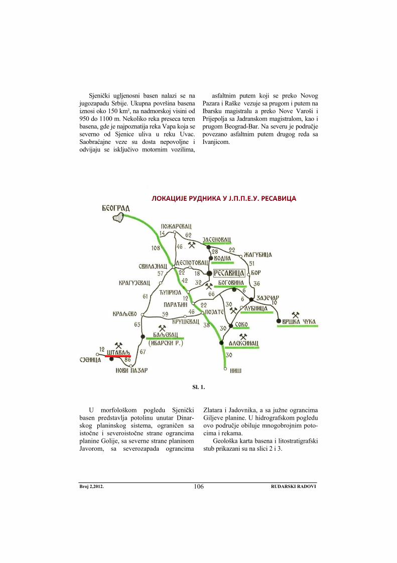
Broj 2,2012. RUDARSKI RADOVI
106
Sjenički ugljenosni basen nalazi se na jugozapadu Srbije. Ukupna površina basena iznosi oko 150 km², na nadmorskoj visini od 950 do 1100 m. Nekoliko reka preseca teren basena, gde je najpoznatija reka Vapa koja se severno od Sjenice uliva u reku Uvac. Saobraćajne veze su dosta nepovoljne i odvijaju se isključivo motornim vozilima,
asfaltnim putem koji se preko Novog Pazara i Raške vezuje sa prugom i putem na Ibarsku magistralu a preko Nove Varoši i Prijepolja sa Jadranskom magistralom, kao i prugom Beograd-Bar. Na severu je područje povezano asfaltnim putem drugog reda sa Ivanjicom.
Sl. 1.
U morfološkom pogledu Sjenički
basen predstavlja potolinu unutar Dinar-skog planinskog sistema, ograničen sa istočne i severoistočne strane ograncima planine Golije, sa severne strane planinom Javorom, sa severozapada ograncima
Zlatara i Jadovnika, a sa južne ograncima Giljeve planine. U hidrografskom pogledu ovo područje obiluje mnogobrojnim poto-cima i rekama.
Geološka karta basena i litostratigrafski stub prikazani su na slici 2 i 3.
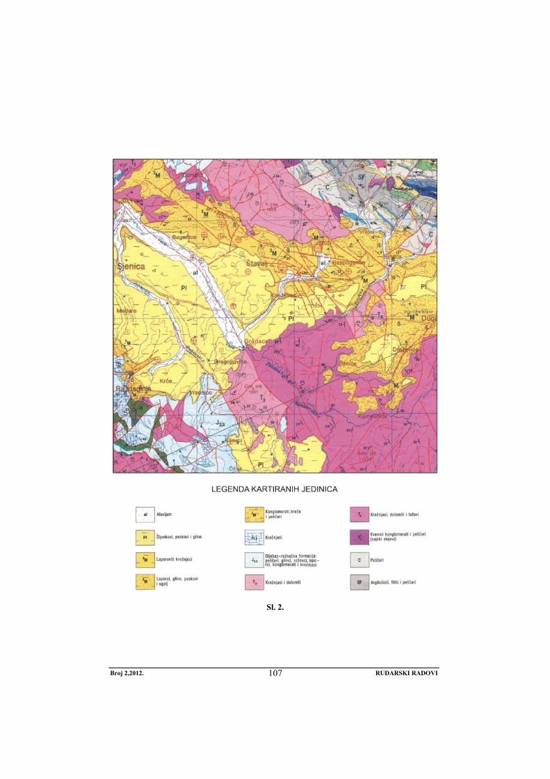
Broj 2,2012. RUDARSKI RADOVI
107
Sl. 2.
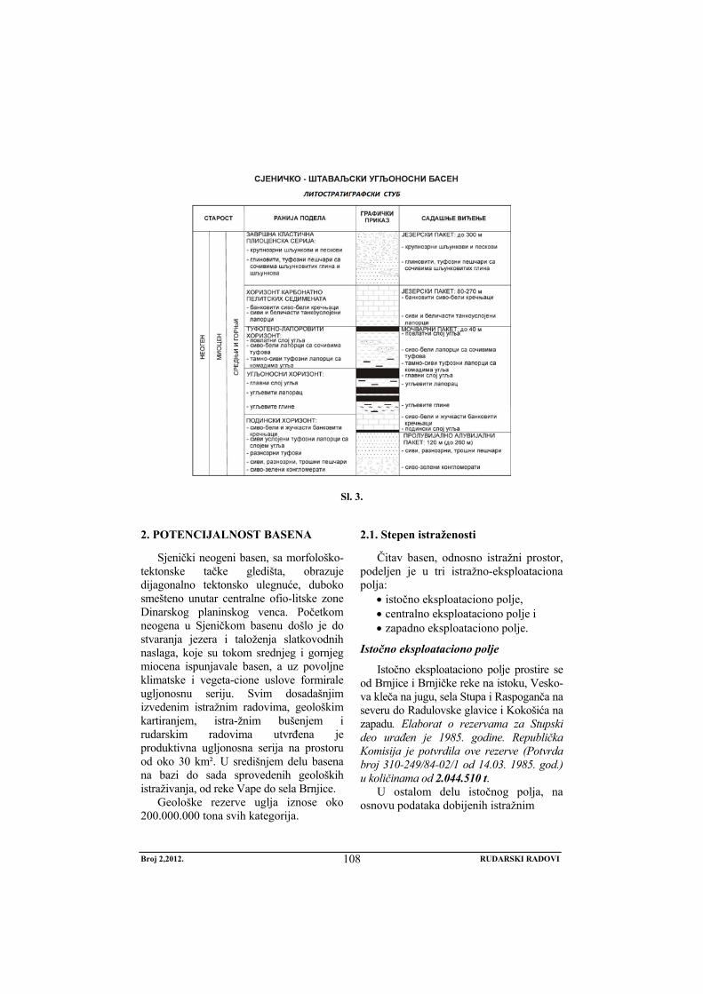
Broj 2,2012. RUDARSKI RADOVI
108
Sl. 3.
2. POTENCIJALNOST BASENA
Sjenički neogeni basen, sa morfološko-tektonske tačke gledišta, obrazuje dijagonalno tektonsko ulegnuće, duboko smešteno unutar centralne ofio-litske zone Dinarskog planinskog venca. Početkom neogena u Sjeničkom basenu došlo je do stvaranja jezera i taloženja slatkovodnih naslaga, koje su tokom srednjeg i gornjeg miocena ispunjavale basen, a uz povoljne klimatske i vegeta-cione uslove formirale ugljonosnu seriju. Svim dosadašnjim izvedenim istražnim radovima, geološkim kartiranjem, istra-žnim bušenjem i rudarskim radovima utvrđena je produktivna ugljonosna serija na prostoru od oko 30 km². U središnjem delu basena na bazi do sada sprovedenih geoloških istraživanja, od reke Vape do sela Brnjice.
Geološke rezerve uglja iznose oko 200.000.000 tona svih kategorija.
2.1. Stepen istraženosti
Čitav basen, odnosno istražni prostor, podeljen je u tri istražno-eksploataciona polja:
• istočno eksploataciono polje, • centralno eksploataciono polje i • zapadno eksploataciono polje.
Istočno eksploataciono polje
Istočno eksploataciono polje prostire se od Brnjice i Brnjičke reke na istoku, Vesko-va kleča na jugu, sela Stupa i Raspoganča na severu do Radulovske glavice i Kokošića na zapadu. Elaborat o rezervama za Stupski deo urađen je 1985. godine. Republička Komisija je potvrdila ove rezerve (Potvrda broj 310-249/84-02/1 od 14.03. 1985. god.) u količinama od 2.044.510 t.
U ostalom delu istočnog polja, na osnovu podataka dobijenih istražnim
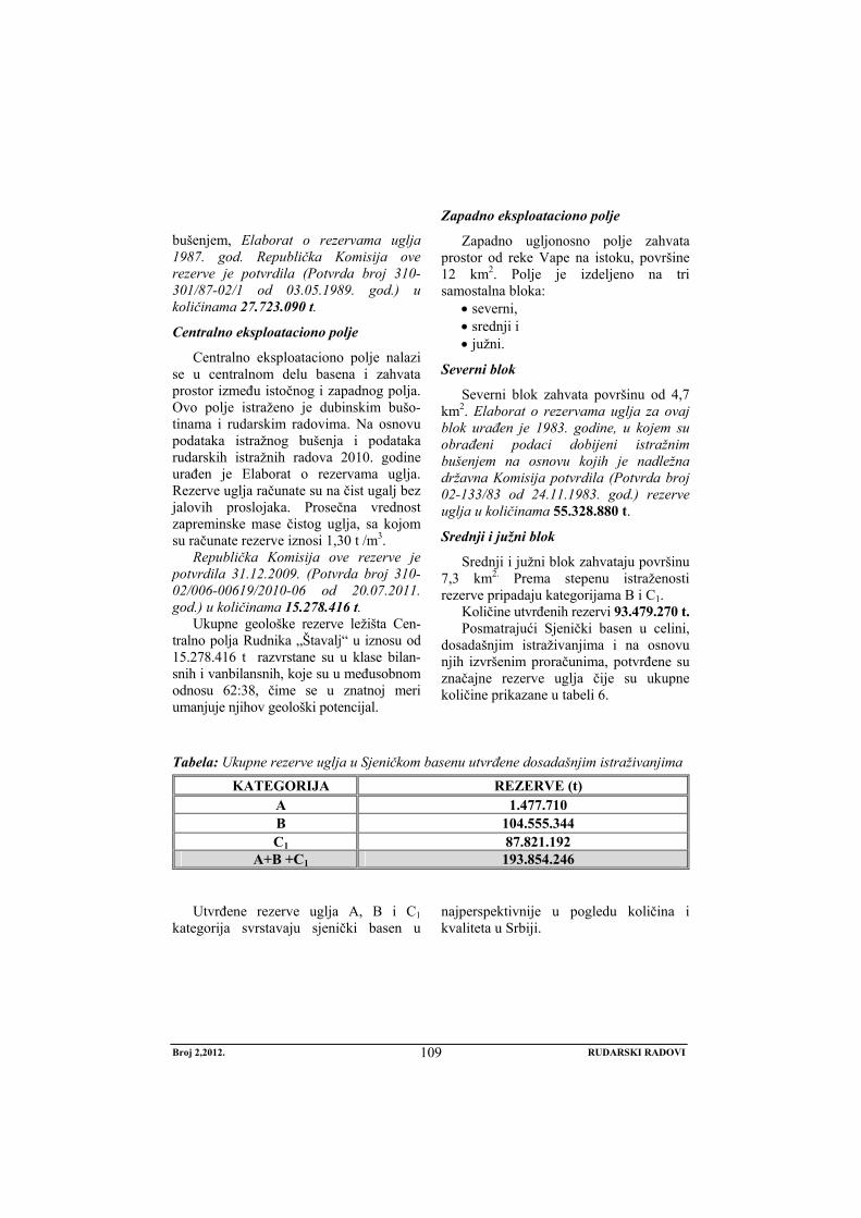
Broj 2,2012. RUDARSKI RADOVI
109
bušenjem, Elaborat o rezervama uglja 1987. god. Republička Komisija ove rezerve je potvrdila (Potvrda broj 310-301/87-02/1 od 03.05.1989. god.) u količinama 27.723.090 t.
Centralno eksploataciono polje
Centralno eksploataciono polje nalazi se u centralnom delu basena i zahvata prostor između istočnog i zapadnog polja. Ovo polje istraženo je dubinskim bušo-tinama i rudarskim radovima. Na osnovu podataka istražnog bušenja i podataka rudarskih istražnih radova 2010. godine urađen je Elaborat o rezervama uglja. Rezerve uglja računate su na čist ugalj bez jalovih proslojaka. Prosečna vrednost zapreminske mase čistog uglja, sa kojom su računate rezerve iznosi 1,30 t /m3.
Republička Komisija ove rezerve je potvrdila 31.12.2009. (Potvrda broj 310-02/006-00619/2010-06 od 20.07.2011. god.) u količinama 15.278.416 t.
Ukupne geološke rezerve ležišta Cen-tralno polja Rudnika „Štavalj“ u iznosu od 15.278.416 t razvrstane su u klase bilan-snih i vanbilansnih, koje su u međusobnom odnosu 62:38, čime se u znatnoj meri umanjuje njihov geološki potencijal.
Zapadno eksploataciono polje
Zapadno ugljonosno polje zahvata prostor od reke Vape na istoku, površine 12 km2. Polje je izdeljeno na tri samostalna bloka:
• severni, • srednji i • južni.
Severni blok
Severni blok zahvata površinu od 4,7 km2. Elaborat o rezervama uglja za ovaj blok urađen je 1983. godine, u kojem su obrađeni podaci dobijeni istražnim bušenjem na osnovu kojih je nadležna državna Komisija potvrdila (Potvrda broj 02-133/83 od 24.11.1983. god.) rezerve uglja u količinama 55.328.880 t.
Srednji i južni blok
Srednji i južni blok zahvataju površinu 7,3 km2. Prema stepenu istraženosti rezerve pripadaju kategorijama B i C1.
Količine utvrđenih rezervi 93.479.270 t. Posmatrajući Sjenički basen u celini,
dosadašnjim istraživanjima i na osnovu njih izvršenim proračunima, potvrđene su značajne rezerve uglja čije su ukupne količine prikazane u tabeli 6.
Tabela: Ukupne rezerve uglja u Sjeničkom basenu utvrđene dosadašnjim istraživanjima
Utvrđene rezerve uglja A, B i C1
kategorija svrstavaju sjenički basen u najperspektivnije u pogledu količina i kvaliteta u Srbiji.
KATEGORIJA REZERVE (t) A 1.477.710 B 104.555.344 C1 87.821.192
A+B +C1 193.854.246
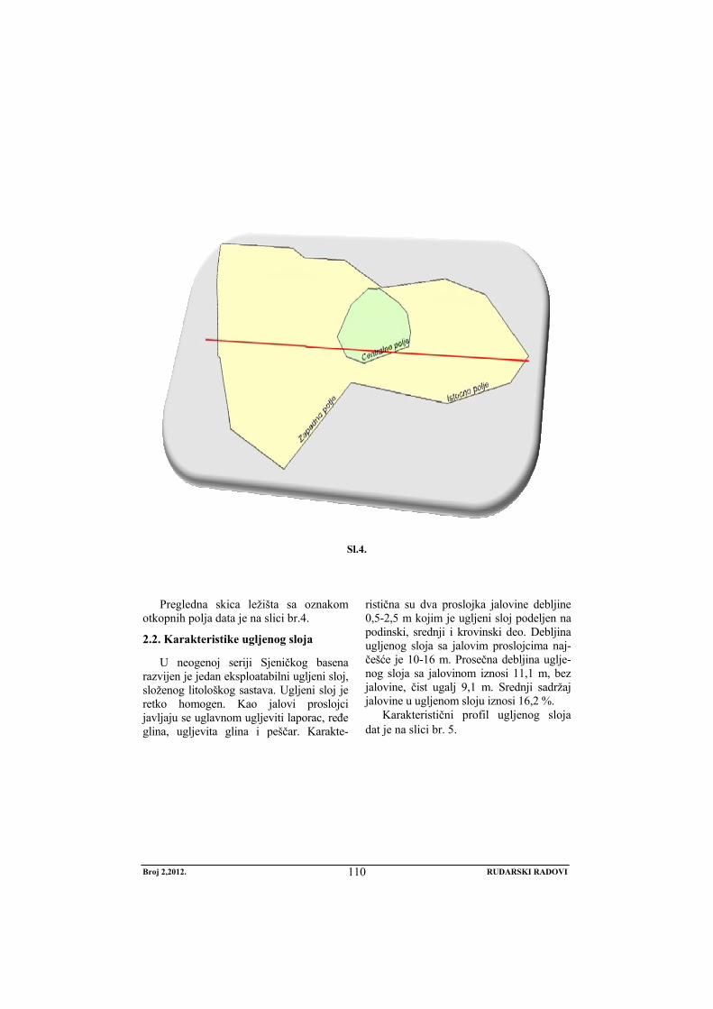
Broj 2,2012. RUDARSKI RADOVI
110
Sl.4.
Pregledna skica ležišta sa oznakom otkopnih polja data je na slici br.4.
2.2. Karakteristike ugljenog sloja
U neogenoj seriji Sjeničkog basena razvijen je jedan eksploatabilni ugljeni sloj, složenog litološkog sastava. Ugljeni sloj je retko homogen. Kao jalovi proslojci javljaju se uglavnom ugljeviti laporac, ređe glina, ugljevita glina i peščar. Karakte-
ristična su dva proslojka jalovine debljine 0,5-2,5 m kojim je ugljeni sloj podeljen na podinski, srednji i krovinski deo. Debljina ugljenog sloja sa jalovim proslojcima naj-češće je 10-16 m. Prosečna debljina uglje-nog sloja sa jalovinom iznosi 11,1 m, bez jalovine, čist ugalj 9,1 m. Srednji sadržaj jalovine u ugljenom sloju iznosi 16,2 %.
Karakteristični profil ugljenog sloja dat je na slici br. 5.
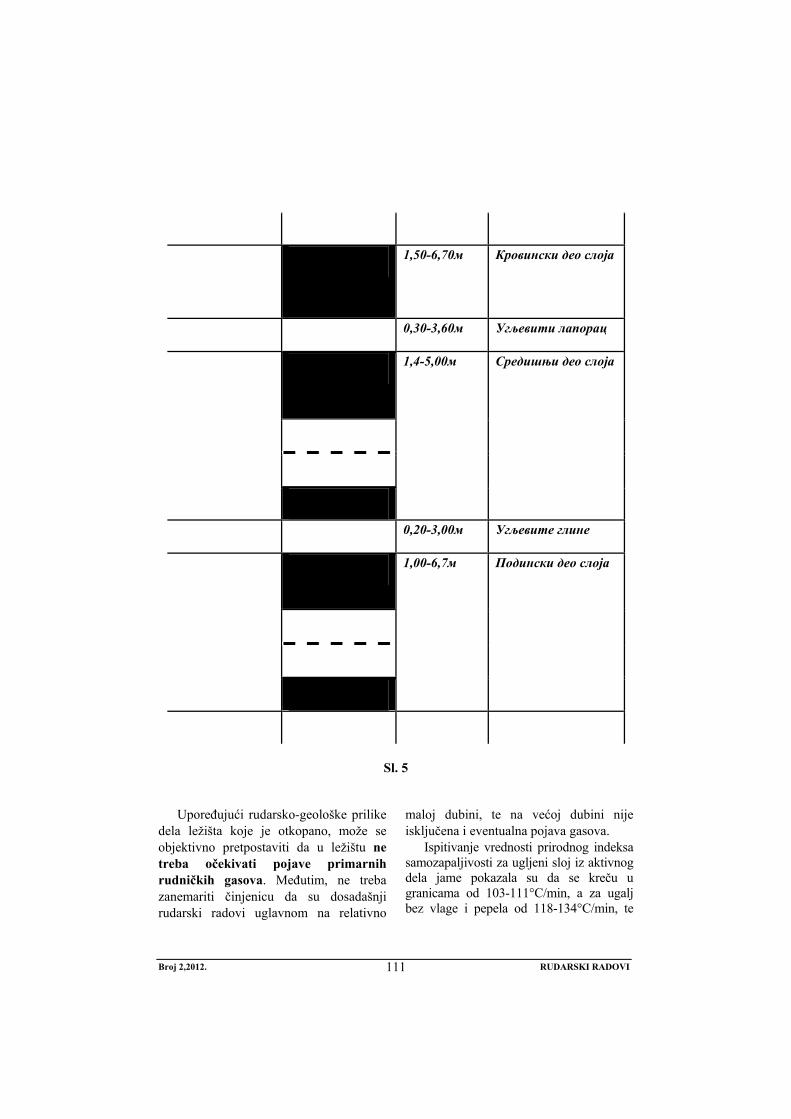
Broj 2,2012. RUDARSKI RADOVI
111
1,50-6,70м Кровински део слоја
0,30-3,60м Угљевити лапорац
1,4-5,00м Средишњи део слоја
0,20-3,00м Угљевите глине
1,00-6,7м Подински део слоја
Sl. 5
Upoređujući rudarsko-geološke prilike
dela ležišta koje je otkopano, može se objektivno pretpostaviti da u ležištu ne treba očekivati pojave primarnih rudničkih gasova. Međutim, ne treba zanemariti činjenicu da su dosadašnji rudarski radovi uglavnom na relativno
maloj dubini, te na većoj dubini nije isključena i eventualna pojava gasova.
Ispitivanje vrednosti prirodnog indeksa samozapaljivosti za ugljeni sloj iz aktivnog dela jame pokazala su da se kreču u granicama od 103-111°C/min, a za ugalj bez vlage i pepela od 118-134°C/min, te
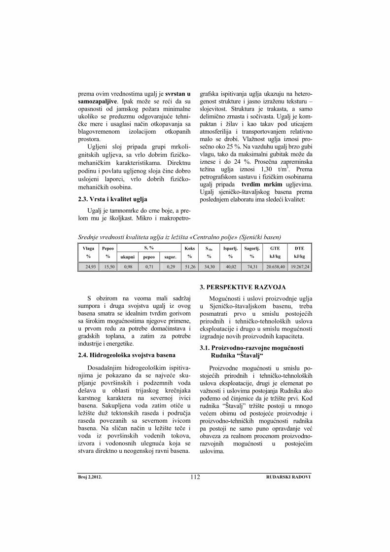
Broj 2,2012. RUDARSKI RADOVI
112
prema ovim vrednostima ugalj je svrstan u samozapaljive. Ipak može se reći da su opasnosti od jamskog požara minimalne ukoliko se preduzmu odgovarajuće tehni-čke mere i usaglasi način otkopavanja sa blagovremenom izolacijom otkopanih prostora.
Ugljeni sloj pripada grupi mrkoli-gnitskih ugljeva, sa vrlo dobrim fizičko-mehaničkim karakteristikama. Direktnu podinu i povlatu ugljenog sloja čine dobro uslojeni laporci, vrlo dobrih fizičko-mehaničkih osobina.
2.3. Vrsta i kvalitet uglja
Ugalj je tamnomrke do crne boje, a pre-lom mu je školjkast. Mikro i makropetro-
grafska ispitivanja uglja ukazuju na hetero-genost strukture i jasno izraženu teksturu – slojevitost. Struktura je trakasta, a samo delimično zrnasta i sočivasta. Ugalj je kom-paktan i žilav i kao takav pod uticajem atmosferilija i transportovanjem relativno malo se drobi. Vlažnost uglja iznosi pro-sečno oko 25 %. Na vazduhu ugalj brzo gubi vlagu, tako da maksimalni gubitak može da iznese i do 24 %. Prosečna zapreminska težina uglja iznosi 1,30 t/m3. Prema petrografskom sastavu i fizičkim osobinama ugalj pripada tvrdim mrkim ugljevima. Ugalj sjeničko-štavaljskog basena prema poslednjem elaboratu ima sledeći kvalitet:
Srednje vrednosti kvaliteta uglja iz ležišta «Centralno polje» (Sjenički basen) S, % Vlaga
%
Pepeo
% ukupni pepeo sagor.
Koks
%
S-fix
%
Isparlj.
%
Sagorlj.
%
GTE
kJ/kg
DTE
kJ/kg
24,93 15,50 0,98 0,71 0,29 51,26 34,30 40,02 74,31 20.638,40 19.267,24
S obzirom na veoma mali sadržaj
sumpora i druga svojstva ugalj iz ovog basena smatra se idealnim tvrdim gorivom sa širokim mogućnostima njegove primene, u prvom redu za potrebe domaćinstava i gradskih toplana, a zatim za potrebe industrije i energetike.
2.4. Hidrogeološka svojstva basena
Dosadašnjim hidrogeološkim ispitiva-njima je pokazano da se najveće sku-pljanje površinskih i podzemnih voda dešava u oblasti trijaskog krečnjaka karstnog karaktera na severnoj ivici basena. Sakupljena voda zatim otiče u ležište duž tektonskih raseda i područja raseda povezanih sa severnom ivicom basena. Na sličan način u ležište teče i voda iz površinskih vodenih tokova, izvora i vodonosnih ulegnuća koja se stvara direktno u neogenskoj ravni basena.
3. PERSPEKTIVE RAZVOJA
Mogućnosti i uslovi proizvodnje uglja u Sjeničko-štavaljskom basenu, treba posmatrati prvo u smislu postojećih prirodnih i tehničko-tehnoloških uslova eksploatacije i drugo u smislu mogućnosti izgradnje novih proizvodnih kapaciteta.
3.1. Proizvodno-razvojne mogućnosti Rudnika “Štavalj“
Proizvodne mogućnosti u smislu po-stojećih prirodnih i tehničko-tehnoloških uslova eksploatacije, drugi je elemenat po važnosti i uslovima postojanja Rudnika ako pođemo od činjenice da je tržište prvi. Kod rudnika “Štavalj” tržište postoji u mnogo većem obimu od postojeće proizvodnje i proizvodno-tehničkih mogućnosti rudnika pa postoji ne samo puno opravdanje već obaveza za realnom procenom proizvodno-razvojnih mogućnosti u postojećim uslovima.
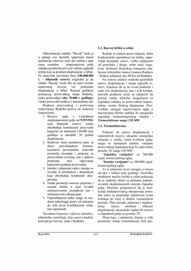
Broj 2,2012. RUDARSKI RADOVI
113
Mikrolokacija rudnika “Štavalj” kada je
u pitanju ceo Sjenički ugljenosni basen predstavlja relativno mali deo ležišta a ipak samo centralno – eksploataciono polje rudnika predstavlja prvi red veličina ugljenih ležišta koji su predmet eksploatacije u Srbiji. Sa stanovišta sirovinske baze (186.000.000 t. – bilansnih rezervi) očigledno je da rudnik “Štavalj” može biti ne samo nosilac sopstvenog razvoja već podzemne eksploatacije u Srbiji. Reperni problemi postojećeg proizvodnog stanja Rudnika, niska proizvodnja (oko 70.000 t. godišnje) visoki proizvodni troškovi i nerentabilan rad.
Realnost proizvodnog i poslovnog ozdravljenja Rudnika počiva na sledećim činjenicama:
1. Rezerve uglja u Centralnom eksploatacionom polju od 9.519.554. tona bilansnih rezervi, realno obezbeđuju kontinuirani proizvodni kapacitet od minimum 130.000 tona godišnje u narednih 30 godina eksploatacije.
2. Relativno mala razuđenost jame sa skoro pravolinijskom komuni-kacionom povezanošću osnovnih prostorija otvaranja i pripreme sa proizvodnim revirima, kao i njihova propustna moć odgovaraju kapacitetu godišnje proizvodnje.
3. Istražni i pripremni radovi moraju se izvoditi sa prioritetom i dinamikom koja obezbeđuje kontinuitet otko-pavanja.
4. Izrada prostorija osnovne pripreme i razrade ležišta u jami izvoditi mehanizovanim postupkom kao i mehanizovano otkopavanje.
5. Osposobljenost radne snage za mo-derne tehnologije počev od inženjera do svih nivoa kvalifikacione struk-ture zaposlenih.
Navedene činjenice i njihovo tehničko-tehnološko razrešenje, čine osnovu buduće koncepcije razvoja jame i Rudnika.
3.2. Razvoj ležišta u celini
Rudnik sa malom proizvodnjom, slaba konkurentska sposobnost na tržištu, nepo-voljni klimatski uslovi, velika udaljenost od potrošača i drugo, treba istaći nega-tivne okolnosti drumskog transporta uda-ljenost železničke stanice (stanica Rudnica - Raška) udaljenoj oko 60 km od Rudnika.
Na osnovu analize rudarsko-geoloških uslova eksploatacije i stanja ugljenih re-zervi, činjenice da se na ovom području i sada vrši eksploatacija, kao i svih kompa-rativnih prednosti može se zaključiti da postoje realne tehničke mogućnosti za izgradnju rudnika sa proizvodnim kapaci-tetima veoma širokog dijapazona. Proi-zvodnju energije sagorevanjem uglja u neposrednoj blizini rudnika bi omogućila izgradnja termoenergetskog objekta - Termoelektrane snage 250 MW.
3.3. Termoelektrana
Polazeći od uslova eksploatacije i raspoloživih rezervi, aktuelne energetske situacije u zemlji, zatim kvaliteta uglja, mogu se razmatrati sledeće varijante proizvodnog kapaciteta koje bi zadovoljilo potrebe TE snage 250 MW.
“Zapadna varijanta“ sa 700.000 t/god. komercijalnog uglja,
“Istočna varijanta“ sa 300.000 t/god. komercijalnog uglja,
To je planirani izvor energije u iznosu od oko 1 milion tona godišnje. Geološko strukturne analize ležišta u celini pokazuju da je najbolja oblast za primenu mehani-zovanih eksploatacionih sistema Zapadno polje. Možemo pretpostaviti da je kori-šćenje mehanizovanog otkopavanja potre-ban uslov za postizanje isplativosti (cena koštanja po toni) u dužem vremenskom periodu. Plan razrade, pripreme i eksploa-tacije rešava problem efikasne eksploatacije ekonomski isplativih rezervi u Zapadnom polju za potrebe TE.
Zbog toga, s namerom, imamo u vidu parametre manje koncentracije kod pro-
Broj 2,2012. RUDARSKI RADOVI
114
storija i otkopnih čela. Sa druge strane, nakon proveravanja povoljnih eksploa-tacionih uslova u Zapadnom polju, koje jedino može, u ovoj fazi, biti uzeto u obzir, na osnovu iskustva prilikom otko-pavanja u Centralnom polju, razrada, priprema i eksploatacija mogu postati efi-kasniji.
Detaljno analizirajući rudarsko-geol-oške uslove Zapadnog polja, mišljenja smo da se može napraviti Rudnik kapa-citeta 700.000 t/god. komercijalnog uglja. Lokacija Termoelektrane bi bila baš u neposrednoj blizini na izlazu iz Štavaljske klisure, bliže Mravin polju.
Izgradnja proizvodnog kapaciteta po “Zapadnoj varijanti“ vršila bi se u Severnom bloku zapadnog polja gde su rezerve uglja oko 55.000.000 tona. Mikrolokacija jame bi se nalazila u Mravin polju. Postojeća infrastruktura Rudnika “Štavalj bi u potpunosti zadovoljavala potrebe jame “Mravin polje”.
Za potrebe proizvodnje po Istočnoj varijanti izgradio bi se moderni manji Rudnik na mikrolokaciji Vilujak nekih 600 m od asfaltnog puta ka selu Stup. Iz ove jame zahvatale bi se rezerve uglja Istočnog polja u količinama od 200.000 t/god. komercijalnog uglja istočno prema selu Veskovićima i zapadno prema jami rudnika “Štavalj”.
Ostatak od 130.000 t/god. komerci-jalnog uglja do milion tona koliko je po-trebno za TE snage 250 MW obezbeđivala bi postojeća jama RMU „Štavalj”.
Sa proizvodnjom iz postojeće jame rudnika “Štavalj” ukupna proizvodnja iz celog basena iznosila bi oko 1.000.000 t/god. komercijalnog uglja. Ove količine uglja predstavljale bi veću proizvodnju od celokupne sadašnje proizvodnje JP za PEU “Resavica“.
LITERATURA
[1] D. Đukanović, M. Denić, D. Dragojević, Brzina izrade podzemnih prostorija, kao uslov uvođenja meha-nizovane izrade podzemnih prostorija u rudnicima JP PEU Resavica, Časopis Rudarski radovi 1(2011), Bor, str. 167-170.
[2] D. Đukanović, M. Popović, D. Zečević, Ekonomski efekti upotrebe jalovine iz separacije uglja Ibarskih rudnika, Časopis Rudarski radovi 1(2011), Bor, str. 187-190.
[3] M. Ivković, J. Miljanović, Izračunavanje koncentacije gasova pri podzemnom sagorevanju uglja, Časopis Rudarski radovi 1(2010), Bor, str. 127-130.
[4] M. Plasto, Analiza rizika i hazarda evidentiranih u RMU Kakanj, Časopis Rudarski radovi 4(2011), Bor, str. 105-118.
[5] S. Ćosić, H. Okanović, Modeliranje naponsko-deformacijskog stanja nu-meričkim metodama kod širokočelnog otkopavanja, Časopis Rudarski radovi 2(2010), Bor, str. 53-72.
No 2, 2012. MINING ENGINEERING
115
MINING AND METALLURGY INSTITUTE BOR YU ISSN: 1451-0162 COMMITTEE OF UNDERGROUND EXPLOITATION OF THE MINERAL DEPOSITS UDK: 622
UDK: 622.332:622.261.2:621.311.24 (045)=20
Mensud Turković*, Dragomir Bukumirović*, Gojko Radeka*, Safet Mušović*
POTENTIALITY AND PROSPECTS OF UNDERGROUND COAL MINING IN THE SJENICA COAL BASIN
Abstract
The current level of exploration the Sjenica Basin with undeniably proven large reserves of quality coal, confirms that this is the most prospective coal deposit in the Republic Srpska for underground mining. Total explored geological coal reserves until now of approximately 20% of explored area are around 194 million tons of coal.
Based on the analysis of mining-geological conditions of mining the coal reserves and balances, the fact of current mining in this area, and all comparative advantages, it can be concluded that there are real technical possibilities for construction the mine with production capacity of a very wide range.
Production of energy by coal combustion in the immediate vicinity of the mine requires the construction of the facility of Thermal Power Plant of 250 MW.
Comprehensive analysis the current state of the pit of the Mine "Štavalj" shows that by implementing the optimization program, based on mining-geological conditions of exploitation and stateof coal reserves in the Basin, it can be concluded that there are real opportunities to construct several underground production systems - pits.
The existing mine pit with production of 130,000 tons per year - The pit “Western Variant“ with production of 700,000 tons per year - The pit “Eastern Variant“ with production of 200,000 tons per year
With the existing pit, in the second stage of development of the Basin, it can be possible to produce annually about 1 million tons of coal from the underground mining.
It enables the construction of the facility of Thermal Power Plant of 250 MW at the location exit from the Štavalj gorge towards the Mravin field.
Keywords: coal basin, coal mine, underground mining, coal combustion, thermal power plant
* JP PEU Resavica, Rudnik „Štavalj“-Sjenica
1. INTRODUCTION
Geological explorations the wider area of the Sjenica Basin have found out large reserves of quality brown lignite coal that represent a significant potential for energy
potential and raw materials for the mine with underground exploitation with higher capacity for the conditions in Serbia.
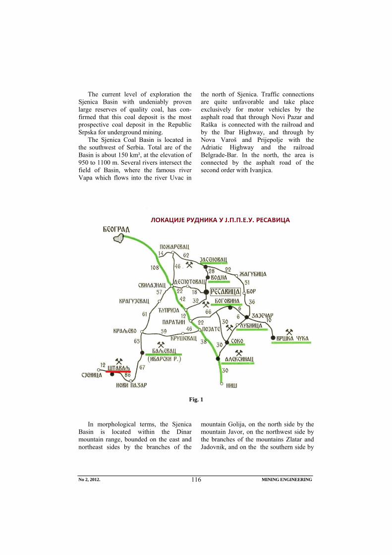
No 2, 2012. MINING ENGINEERING
116
The current level of exploration the Sjenica Basin with undeniably proven large reserves of quality coal, has con-firmed that this coal deposit is the most prospective coal deposit in the Republic Srpska for underground mining.
The Sjenica Coal Basin is located in the southwest of Serbia. Total are of the Basin is about 150 km², at the elevation of 950 to 1100 m. Several rivers intersect the field of Basin, where the famous river Vapa which flows into the river Uvac in
the north of Sjenica. Traffic connections are quite unfavorable and take place exclusively for motor vehicles by the asphalt road that through Novi Pazar and Raška is connected with the railroad and by the Ibar Highway, and through by Nova Varoš and Prijepolje with the Adriatic Highway and the railroad Belgrade-Bar. In the north, the area is connected by the asphalt road of the second order with Ivanjica.
Fig. 1
In morphological terms, the Sjenica
Basin is located within the Dinar mountain range, bounded on the east and northeast sides by the branches of the
mountain Golija, on the north side by the mountain Javor, on the northwest side by the branches of the mountains Zlatar and Jadovnik, and on the the southern side by
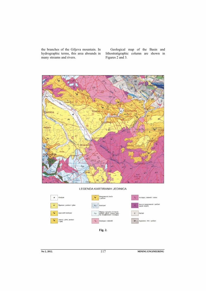
No 2, 2012. MINING ENGINEERING
117
the branches of the Giljeva mountain. In hydrographic terms, this area abounds in many streams and rivers.
Geological map of the Basin and lithostratigraphic column are shown in Figures 2 and 3.
Fig. 2.
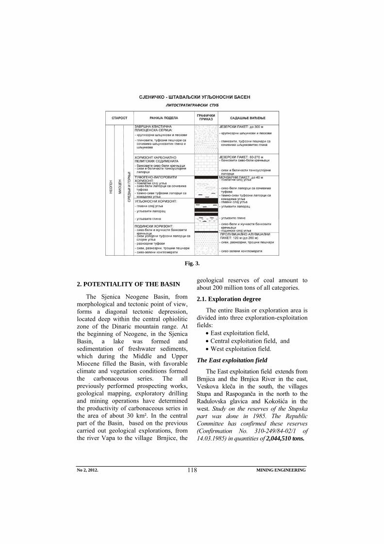
No 2, 2012. MINING ENGINEERING
118
Fig. 3.
2. POTENTIALITY OF THE BASIN
The Sjenica Neogene Basin, from morphological and tectonic point of view, forms a diagonal tectonic depression, located deep within the central ophiolitic zone of the Dinaric mountain range. At the beginning of Neogene, in the Sjenica Basin, a lake was formed and sedimentation of freshwater sediments, which during the Middle and Upper Miocene filled the Basin, with favorable climate and vegetation conditions formed the carbonaceous series. The all previously performed prospecting works, geological mapping, exploratory drilling and mining operations have determined the productivity of carbonaceous series in the area of about 30 km². In the central part of the Basin, based on the previous carried out geological explorations, from the river Vapa to the village Brnjice, the
geological reserves of coal amount to about 200 million tons of all categories.
2.1. Exploration degree
The entire Basin or exploration area is divided into three exploration-exploitation fields:
• East exploitation field, • Central exploitation field, and • West exploitation field.
The East exploitation field
The East exploitation field extends from Brnjica and the Brnjica River in the east, Veskova kleča in the south, the villages Stupa and Raspoganča in the north to the Radulovska glavica and Kokošića in the west. Study on the reserves of the Stupska part was done in 1985. The Republic Committee has confirmed these reserves (Confirmation No. 310-249/84-02/1 of 14.03.1985) in quantities of 2,044,510 tons.
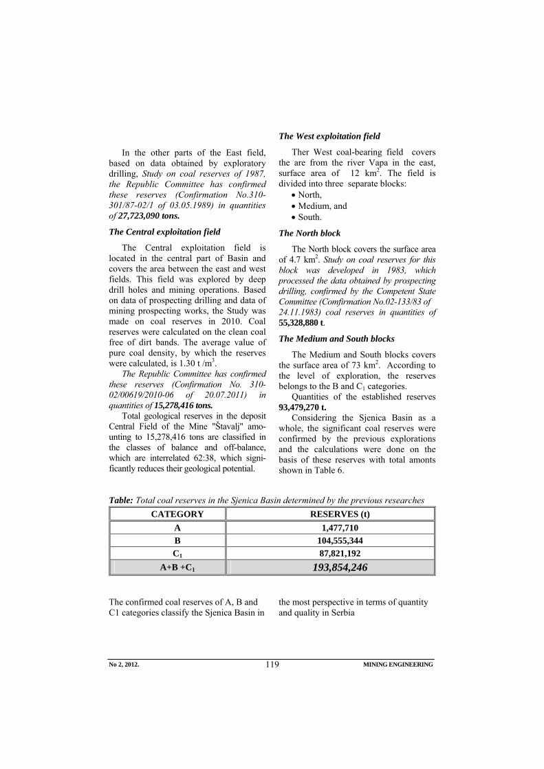
No 2, 2012. MINING ENGINEERING
119
In the other parts of the East field,
based on data obtained by exploratory drilling, Study on coal reserves of 1987, the Republic Committee has confirmed these reserves (Confirmation No.310-301/87-02/1 of 03.05.1989) in quantities of 27,723,090 tons.
The Central exploitation field
The Central exploitation field is located in the central part of Basin and covers the area between the east and west fields. This field was explored by deep drill holes and mining operations. Based on data of prospecting drilling and data of mining prospecting works, the Study was made on coal reserves in 2010. Coal reserves were calculated on the clean coal free of dirt bands. The average value of pure coal density, by which the reserves were calculated, is 1.30 t /m3.
The Republic Committee has confirmed these reserves (Confirmation No. 310-02/00619/2010-06 of 20.07.2011) in quantities of 15,278,416 tons.
Total geological reserves in the deposit Central Field of the Mine "Štavalj" amo-unting to 15,278,416 tons are classified in the classes of balance and off-balance, which are interrelated 62:38, which signi-ficantly reduces their geological potential.
The West exploitation field
Ther West coal-bearing field covers the are from the river Vapa in the east, surface area of 12 km2. The field is divided into three separate blocks:
• North, • Medium, and • South.
The North block
The North block covers the surface area of 4.7 km2. Study on coal reserves for this block was developed in 1983, which processed the data obtained by prospecting drilling, confirmed by the Competent State Committee (Comfirmation No.02-133/83 of 24.11.1983) coal reserves in quantities of 55,328,880 t.
The Medium and South blocks
The Medium and South blocks covers the surface area of 73 km2. According to the level of exploration, the reserves belongs to the B and C1 categories.
Quantities of the established reserves 93,479,270 t.
Considering the Sjenica Basin as a whole, the significant coal reserves were confirmed by the previous explorations and the calculations were done on the basis of these reserves with total amonts shown in Table 6.
Table: Total coal reserves in the Sjenica Basin determined by the previous researches
The confirmed coal reserves of A, B and C1 categories classify the Sjenica Basin in
the most perspective in terms of quantity and quality in Serbia
CATEGORY RESERVES (t) A 1,477,710 B 104,555,344 C1 87,821,192
A+B +C1 193,854,246
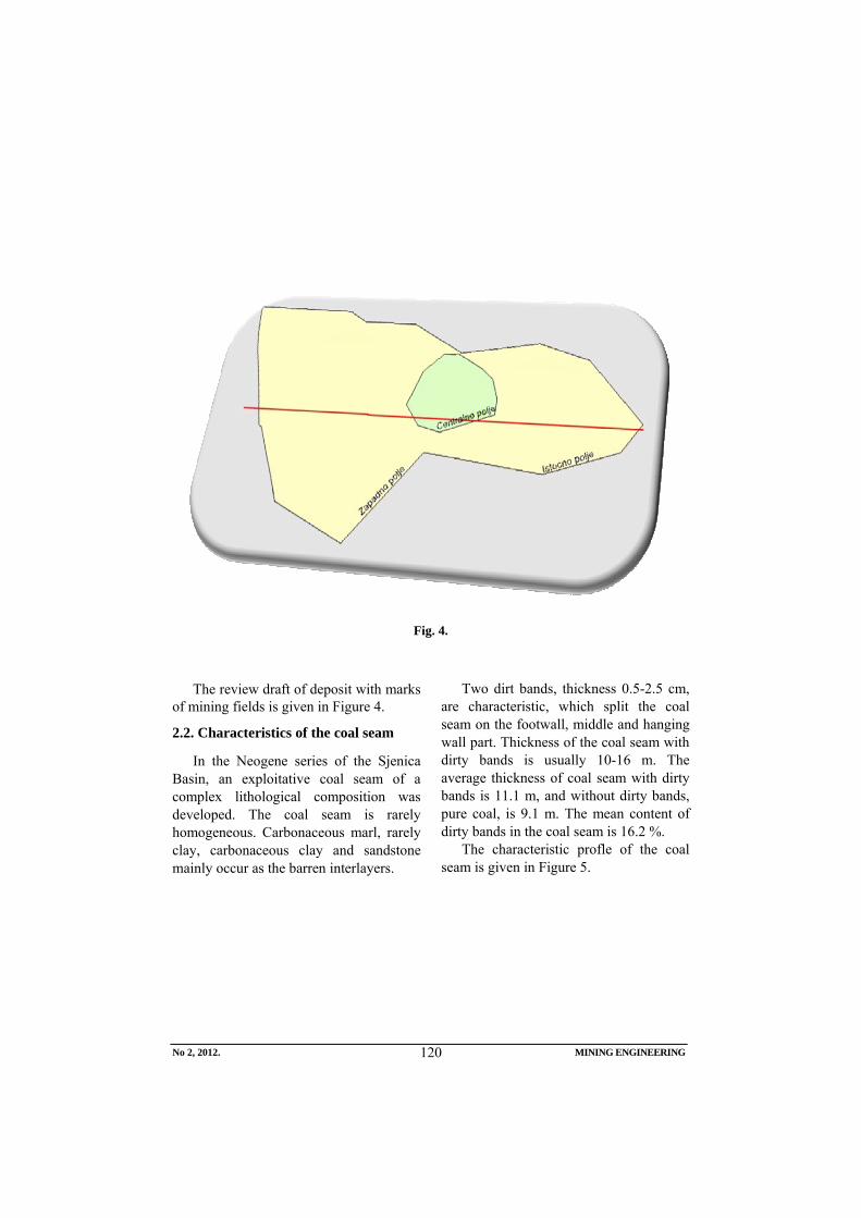
No 2, 2012. MINING ENGINEERING
120
Fig. 4.
The review draft of deposit with marks of mining fields is given in Figure 4.
2.2. Characteristics of the coal seam
In the Neogene series of the Sjenica Basin, an exploitative coal seam of a complex lithological composition was developed. The coal seam is rarely homogeneous. Carbonaceous marl, rarely clay, carbonaceous clay and sandstone mainly occur as the barren interlayers.
Two dirt bands, thickness 0.5-2.5 cm, are characteristic, which split the coal seam on the footwall, middle and hanging wall part. Thickness of the coal seam with dirty bands is usually 10-16 m. The average thickness of coal seam with dirty bands is 11.1 m, and without dirty bands, pure coal, is 9.1 m. The mean content of dirty bands in the coal seam is 16.2 %.
The characteristic profle of the coal seam is given in Figure 5.
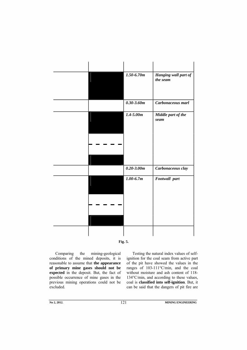
No 2, 2012. MINING ENGINEERING
121
1.50-6.70m Hanging wall part of the seam
0.30-3.60m Carbonaceous marl
1.4-5.00m Middle part of the seam
0.20-3.00m Carbonaceous clay
1.00-6.7m Footwall part
Fig. 5.
Comparing the mining-geological
conditions of the mined deposits, it is reasonable to assume that the appearance of primary mine gases should not be expected in the deposit. But, the fact of possible occurrence of mine gases in the previous mining operations could not be excluded.
Testing the natural index values of self-ignition for the coal seam from active part of the pit have showed the values in the ranges of 103-111°C/min, and the coal without moisture and ash content of 118-134°C/min, and according to these values, coal is classified into self-ignition. But, it can be said that the dangers of pit fire are
No 2, 2012. MINING ENGINEERING
122
minimum if the appropriate technical measures are taken and the mining method and timely insulation of excavated rooms are coordinated.
The coal seam belongs to the group of brown lignite coal, with very good physical and mechanical properties. Direct floor and roof of the coal seam include the well-stratified marls of very good physical and mechanical properties.
2.3. Type and quality of coal
Coal is a dark brown to black with shelly fracture. Micro - and macro-petrographic testing of coal indicate heterogeneity of the
structure and clearly expressed texture – bedding. The structure is banded, and only partly granular and lenticular. Coal is compact and tough and, as such, under the influence of weathering and transport it is relatively little crushed. The average moisture content of coal is about 25%. On the air, coal quickly loses moisture, so that maximum loss that can bring up to 24%. The average bulk density of coal is 1.30 t/m3. According to the petrographic composition and physical properties, coal belongs to the hard brown coals. Coal of the Sjenica - Štavalj Basin, according to the latest technical project study has the following qualities:
Mean values of coal quality from the field «Centralno polje» (Sjenica Basin) S, % Moisture
%
Ash
% Total Ash Combustible
Coke
%
S-fix
%
Evaporative
%
Combustible
%
GTE
kJ/kg
DTE
kJ/kg
24.93 15.50 0.98 0.71 0.29 51.26 34.30 40.02 74.31 20,638.40 19,267.24
Considering very low sulfur content and
other characteristics of coal from this Basin, it is considered as an ideal solid fuel with wide possibilities of use, primarily for the needs of households and district heating plants, and for the needs of industry and energy.
2.4. Hydrogeological properties of the Basin
Previous hydrogeological testing has shown that the highest ground and surface water collection occurs in the area of Triassic limestone of karst character on the northern edge of the Basin. Collected water then flows into deposit along tectonic faults and fault areas associated with the northern edge of the Basin. In a similar way, water from the surface water streams, springs and water bearing depressions flows into deposit, formed directly in the Neogene plane of the Basin.
3. PERSPECTIVES OF DEVELOPMENT
Possibilities and conditions of coal production in the Sjenica - Štavalj Basin, should be firstly considered in terms of the existing natural and technical-technological conditions of exploitation and secondly in terms of possibility of construction the new production capacities.
3.1. Production-development options of the Mine “ Štavalj “
Production options, is the second element by priority and conditions of the Mine existence in terms of the existing natural and technical-technological mining conditions is the second element of importance in the conditions of the mine existence, is it starts from the fact that the market is the first element. In the Mine "Štavalj", there is the market in a much larger scale than the existing production and production-technical possibilities of
No 2, 2012. MINING ENGINEERING
123
the mine and it is not only fully justified but obligation to the real evalution the production-development possibilities in existing conditions.
Micro-location of the mine "Štavalj" considering the whole Sjenica Coal Basin is relatively a small part of the deposit and yet only the central - exploitation field of the mine is the first order of coal deposits size that are the subject to exploitation in Serbia. From the standpoint of raw materials (186 million tons - Balance reserves), it is obvious that the mine "Štavalj" cannot be only the holder of its own development but the underground mining in Serbia. The markable problems of the production existing state of the Mine, low production (about 70,000 tons per year) high production costs and unprofitable work.
The reality of production and business recovery of the Mine is based on the following facts:
1.Coal reserves in the Central exploitation field of 9,519,554 tons of balance reserves provide the continuous production capacity of at least 130,000 tons annually over the next 30 years of exploitation.
2.Relatively small branching of the pit with almost straight line of connection the basic rooms by opening and preparation from the mining district, as their corresponding throughput capacity are suitable to the annual production.
3.Prospecting and preparation works have to be done with the priority and dynamics that provides the continuous mining.
4.Drivage of room for basic preparation and development in the pit have to be done using the mechanized method as well as the mechanized mining.
5.Qualifications of the workforce for modern technologies starting from engineers to the all levels of qualified staff structure.
The given facts and their technical-technological solution are the basis for future development concept of the pit and Mine.
3.2. Deposit development as a whole
The mine with low production, weak market competitiveness, unfavorable climatic conditions, large distance from consumers and others; the negative circumstances of road transport have to be emphasized as the distance of railway station (the station Rudnica - Raška) some 60 km away from the Mine.
Based on the analysis of mining-geological conditions of exploitation and condition of the coal reserves, and the fact that in this area the exploitation is underway as well as the all comparative benefits, it can be concluded that there are real technical possibilities for construction of the mine with production capacities of a wide range. Energy production by combustion coal in the immediate vicinity of the mine would allow the construction of the thermal power facility - Power Plant of 250 MW.
3.3. Power Plant
Starting from the conditions of exploitation and available reserves, the current energy situation in the country, then the quality of coal, the following variants of production capacity can be considered that would satisfy the needs of the Power Plant of 250 MW:
“West variant“ with 700,000 t/year of commercial coal.,
“East variant“ with 300,000 t/year of commercial coal.
It is the planned source of energy to the amount of about 1 million tons per year. Geological - structural analyses of deposit as a whole show that the best area for use the mechanized exploitation systems is the West field. It can be assumed that the required condition of cost-effectiveness (costs per ton) is the use
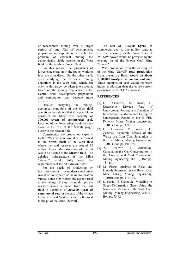
No 2, 2012. MINING ENGINEERING
124
of mechanized mining over a longer period of time. Plan of development, preparation and exploitation will solve the problem of efficient mining the economically viable reserves in the West field for the needs of Power Plant.
For this reason, the parameters of lower concentration in the rooms working face are considered. On the other hand, after verifying the favorable mining conditions in the West field, which can only, at this stage, be taken into account, based on the mining experience in the Central field, development, preparation and exploitation can become more effective.
Detailed analyzing the mining-geological conditions of the West field conditions has shown that it is possible to construct the Mine with capacity of 700,000 t/year of commercial coal. Location of the Power plant would be very close to the exit of the Štavalj gorge, closer to the Mravin field.
Construction the production capacity by the "West version" would be performed in the North block of the West field where the coal reserves are around 55 million tones. Micro-location of the pit would be located in the Mravin field. The existing infrastructure of the Mine “Štavalj” would fully meet the requirements of the pit “Mravin field”.
For the needs of production by the“East variant“ a modern small mine would be constructed at the micro location Vilujak some 600 m from the asphalt road to the village of Stup. From this pi, the reserves would be mined from the East field in quantities of 200,000 t/year of commercial coal in the east of the village to the west and Veskovići and in the west to the pit of the Mine "Štavalj".
The rest of 130,000 t/year of commercial coal to one million tons, as shall be necessary for the Power Plant of 250 MW power, would be provided by the existing pit of the Brown Coal Mine "Štavalj".
With production from the existing pit of the Mine "Štavalj" total production from the entire Basin would be about 1,000,000 tons/year of commercial coal. These amounts of coal would represent higher production than the entire current production of JP PEU "Resavica".
REFERENCES
[1] D. Đukanović, M. Denić, D. Dragojević, Drivage Rate of Underground Rooms, as a Condition of Introduction the Mechanized Drivage of Underground Rooms in the JP PEU Resavica Mines, Mining Engineering, 1(2011), Bor, pp. 171-175.
[2] D. Đukanović, M. Popović, D. Zečević, Economic Effects of the Waste use from Coal Separation in the Ibar Mines, Mining Engineering, 1(2011), Bor, pp. 191-196.
[3] M. Ivković, J. Miljanović, Calculation the Gas Concentration in the Underground Coal Combustion, Mining Engineering, 1(2010), Bor, pp. 131-134.
[4] M. Plasto, Analysis of Risks and Hazards Registered in the Brown Coal Mine Kakanj, Mining Engineering, 1(2010), Bor, pp. 119-130.
[5] S. Ćosić, H. Okanović, Modeling of Stress-Deformation State Using the Numerical Methods in the Wide Face Mining, Mining Engineering, 2(2010), Bor, pp. 73-92.
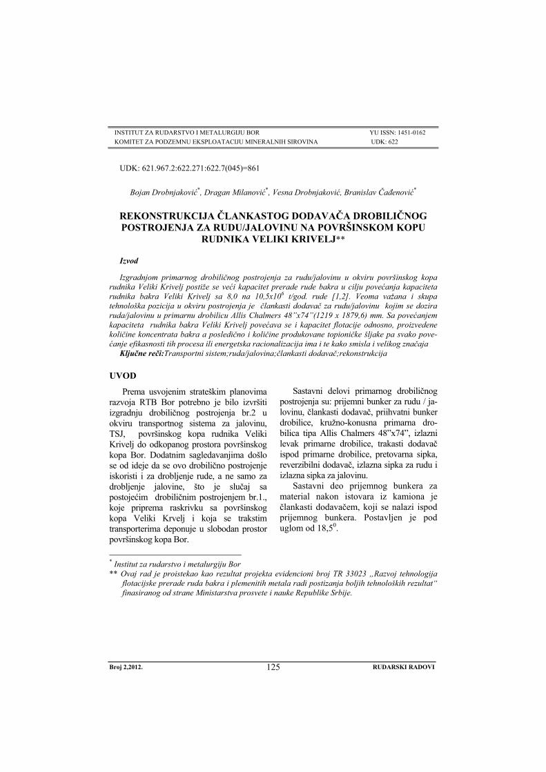
Broj 2,2012. RUDARSKI RADOVI
125
INSTITUT ZA RUDARSTVO I METALURGIJU BOR YU ISSN: 1451-0162 KOMITET ZA PODZEMNU EKSPLOATACIJU MINERALNIH SIROVINA UDK: 622
UDK: 621.967.2:622.271:622.7(045)=861
Bojan Drobnjaković*, Dragan Milanović*, Vesna Drobnjaković, Branislav Čađenović*
REKONSTRUKCIJA ČLANKASTOG DODAVAČA DROBILIČNOG POSTROJENJA ZA RUDU/JALOVINU NA POVRŠINSKOM KOPU
RUDNIKA VELIKI KRIVELJ**
Izvod
Izgradnjom primarnog drobiličnog postrojenja za rudu/jalovinu u okviru površinskog kopa rudnika Veliki Krivelj postiže se veći kapacitet prerade rude bakra u cilju povećanja kapaciteta rudnika bakra Veliki Krivelj sa 8,0 na 10,5x10⁶ t/god. rude [1,2]. Veoma važana i skupa tehnološka pozicija u okviru postrojenja je člankasti dodavač za rudu/jalovinu kojim se dozira ruda/jalovinu u primarnu drobilicu Allis Chalmers 48”x74”(1219 x 1879,6) mm. Sa povećanjem kapaciteta rudnika bakra Veliki Krivelj povećava se i kapacitet flotacije odnosno, proizvedene količine koncentrata bakra a posledično i količine produkovane topioničke šljake pa svako pove-ćanje efikasnosti tih procesa ili energetska racionalizacija ima i te kako smisla i velikog značaja
Ključne reči:Transportni sistem;ruda/jalovina;člankasti dodavač;rekonstrukcija
* Institut za rudarstvo i metalurgiju Bor ** Ovaj rad je proistekao kao rezultat projekta evidencioni broj TR 33023 „Razvoj tehnologija
flotacijske prerade ruda bakra i plemenitih metala radi postizanja boljih tehnoloških rezultat“ finasiranog od strane Ministarstva prosvete i nauke Republike Srbije.
UVOD
Prema usvojenim strateškim planovima razvoja RTB Bor potrebno je bilo izvršiti izgradnju drobiličnog postrojenja br.2 u okviru transportnog sistema za jalovinu, TSJ, površinskog kopa rudnika Veliki Krivelj do odkopanog prostora površinskog kopa Bor. Dodatnim sagledavanjima došlo se od ideje da se ovo drobilično postrojenje iskoristi i za drobljenje rude, a ne samo za drobljenje jalovine, što je slučaj sa postojećim drobiličnim postrojenjem br.1., koje priprema raskrivku sa površinskog kopa Veliki Krvelj i koja se trakstim transporterima deponuje u slobodan prostor površinskog kopa Bor.
Sastavni delovi primarnog drobiličnog
postrojenja su: prijemni bunker za rudu / ja-lovinu, člankasti dodavač, priihvatni bunker drobilice, kružno-konusna primarna dro-bilica tipa Allis Chalmers 48”x74”, izlazni levak primarne drobilice, trakasti dodavač ispod primarne drobilice, pretovarna sipka, reverzibilni dodavač, izlazna sipka za rudu i izlazna sipka za jalovinu.
Sastavni deo prijemnog bunkera za material nakon istovara iz kamiona je člankasti dodavačem, koji se nalazi ispod prijemnog bunkera. Postavljen je pod uglom od 18,50.
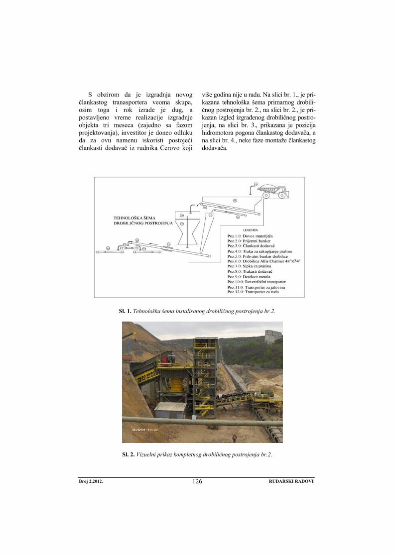
Broj 2,2012. RUDARSKI RADOVI
126
S obzirom da je izgradnja novog člankastog tranasportera veoma skupa, osim toga i rok izrade je dug, a postavljeno vreme realizacije izgradnje objekta tri meseca (zajedno sa fazom projektovanja), investitor je doneo odluku da za ovu namenu iskoristi postojeći člankasti dodavač iz rudnika Cerovo koji
više godina nije u radu. Na slici br. 1., je pri-kazana tehnološka šema primarnog drobili-čnog postrojenja br. 2., na slici br. 2., je pri-kazan izgled izgrađenog drobiličnog postro-jenja, na slici br. 3., prikazana je pozicija hidromotora pogona člankastog dodavača, a na slici br. 4., neke faze montaže člankastog dodavača.
Sl. 1. Tehnološka šema instalisanog drobiličnog postrojenja br.2.
Sl. 2. Vizuelni prikaz kompletnog drobiličnog postrojenja br.2.
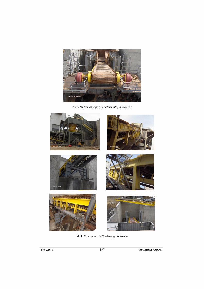
Broj 2,2012. RUDARSKI RADOVI
127
Sl. 3. Hidromotor pogona člankastog dodavača
Sl. 4. Faze montaže člankastog dodavača
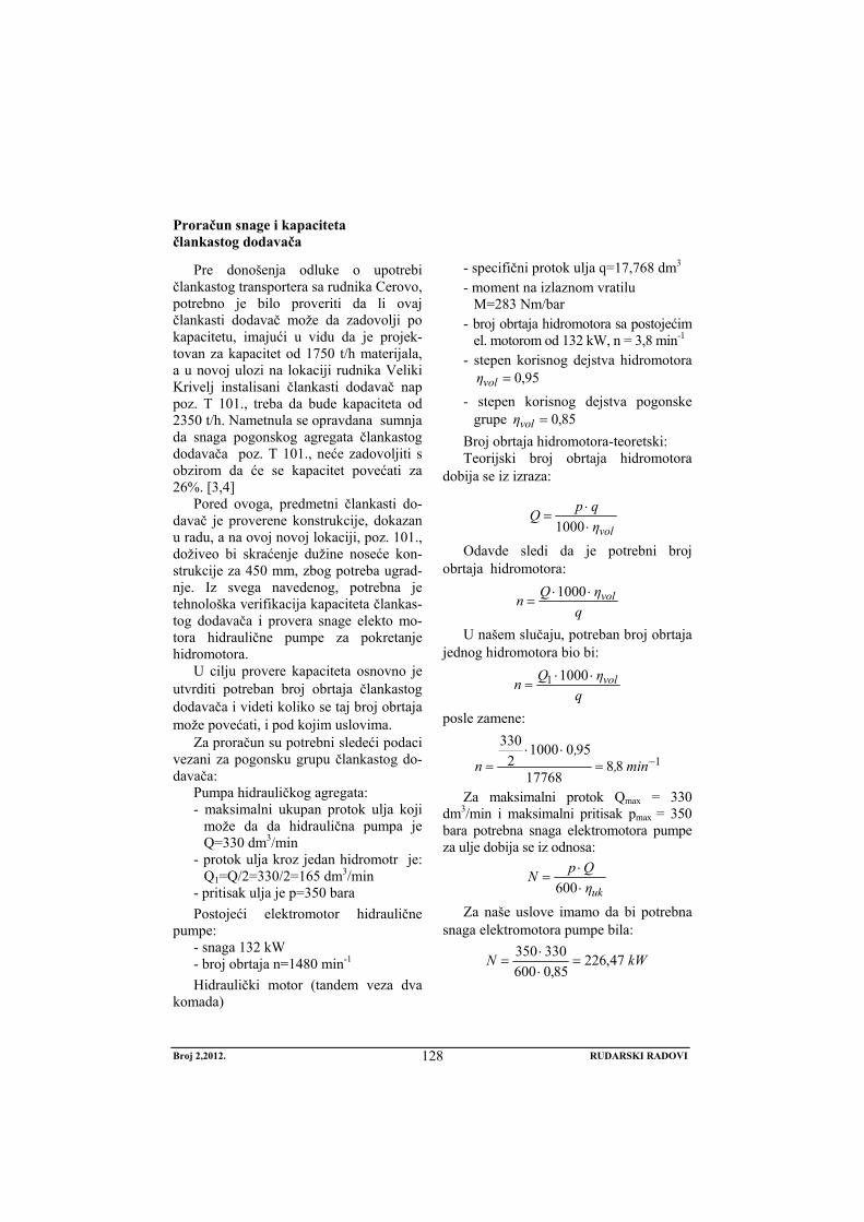
Broj 2,2012. RUDARSKI RADOVI
128
Proračun snage i kapaciteta člankastog dodavača
Pre donošenja odluke o upotrebi člankastog transportera sa rudnika Cerovo, potrebno je bilo proveriti da li ovaj člankasti dodavač može da zadovolji po kapacitetu, imajući u vidu da je projek-tovan za kapacitet od 1750 t/h materijala, a u novoj ulozi na lokaciji rudnika Veliki Krivelj instalisani člankasti dodavač nap poz. T 101., treba da bude kapaciteta od 2350 t/h. Nametnula se opravdana sumnja da snaga pogonskog agregata člankastog dodavača poz. T 101., neće zadovoljiti s obzirom da će se kapacitet povećati za 26%. [3,4]
Pored ovoga, predmetni člankasti do-davač je proverene konstrukcije, dokazan u radu, a na ovoj novoj lokaciji, poz. 101., doživeo bi skraćenje dužine noseće kon-strukcije za 450 mm, zbog potreba ugrad-nje. Iz svega navedenog, potrebna je tehnološka verifikacija kapaciteta člankas-tog dodavača i provera snage elekto mo-tora hidraulične pumpe za pokretanje hidromotora.
U cilju provere kapaciteta osnovno je utvrditi potreban broj obrtaja člankastog dodavača i videti koliko se taj broj obrtaja može povećati, i pod kojim uslovima.
Za proračun su potrebni sledeći podaci vezani za pogonsku grupu člankastog do-davača:
Pumpa hidrauličkog agregata: - maksimalni ukupan protok ulja koji
može da da hidraulična pumpa je Q=330 dm3/min
- protok ulja kroz jedan hidromotr je: Q1=Q/2=330/2=165 dm3/min
- pritisak ulja je p=350 bara Postojeći elektromotor hidraulične
pumpe: - snaga 132 kW - broj obrtaja n=1480 min-1 Hidraulički motor (tandem veza dva
komada)
- specifični protok ulja q=17,768 dm3 - moment na izlaznom vratilu
M=283 Nm/bar - broj obrtaja hidromotora sa postojećim
el. motorom od 132 kW, n = 3,8 min-1 - stepen korisnog dejstva hidromotora
95,0=volη - stepen korisnog dejstva pogonske
grupe 85,0=volη Broj obrtaja hidromotora-teoretski: Teorijski broj obrtaja hidromotora
dobija se iz izraza:
volηqpQ⋅⋅
=1000
Odavde sledi da je potrebni broj obrtaja hidromotora:
qηQn vol⋅⋅
=1000
U našem slučaju, potreban broj obrtaja jednog hidromotora bio bi:
qηQn vol⋅⋅
=10001
posle zamene:
18817768
95010002
330−=
⋅⋅= min,
,n
Za maksimalni protok Qmax = 330 dm3/min i maksimalni pritisak pmax = 350 bara potrebna snaga elektromotora pumpe za ulje dobija se iz odnosa:
ukηQpN⋅⋅
=600
Za naše uslove imamo da bi potrebna snaga elektromotora pumpe bila:
kWN 47,22685,0600
330350=
⋅⋅
=
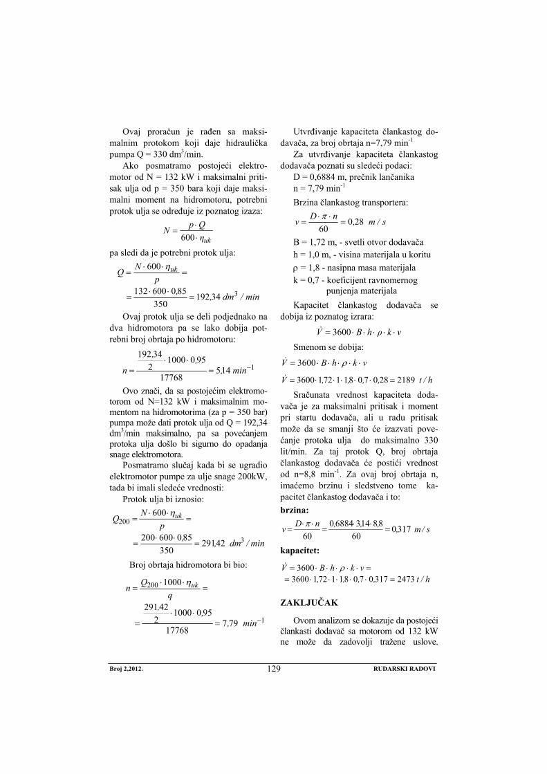
Broj 2,2012. RUDARSKI RADOVI
129
Ovaj proračun je rađen sa maksi-malnim protokom koji daje hidraulička pumpa Q = 330 dm3/min.
Ako posmatramo postojeći elektro-motor od N = 132 kW i maksimalni priti-sak ulja od p = 350 bara koji daje maksi-malni moment na hidromotoru, potrebni protok ulja se određuje iz poznatog izaza:
ukηQpN⋅⋅
=600
pa sledi da je potrebni protok ulja:
min/dm,,p
NQ uk
334192350
850600132
600
=⋅⋅
=
=⋅⋅
=η
Ovaj protok ulja se deli podjednako na dva hidromotora pa se lako dobija pot-rebni broj obrtaja po hidromotoru:
114517768
95010002
34192−=
⋅⋅= min,
,,
n
Ovo znači, da sa postojećim elektromo-torom od N=132 kW i maksimalnim mo-mentom na hidromotorima (za p = 350 bar) pumpa može dati protok ulja od Q = 192,34 dm3/min maksimalno, pa sa povećanjem protoka ulja došlo bi sigurno do opadanja snage elektromotora.
Posmatramo slučaj kada bi se ugradio elektromotor pumpe za ulje snage 200kW, tada bi imali sledeće vrednosti:
Protok ulja bi iznosio:
min/dm,,p
NQ uk
3
200
42291350
850600200
600
=⋅⋅
=
=⋅⋅
=η
Broj obrtaja hidromotora bi bio:
1
200
79717768
95010002
42291
1000
−=⋅⋅
=
=⋅⋅
=
min,,,
qQn ukη
Utvrđivanje kapaciteta člankastog do-davača, za broj obrtaja n=7,79 min-1
Za utvrđivanje kapaciteta člankastog dodavača poznati su sledeći podaci:
D = 0,6884 m, prečnik lančanika n = 7,79 min-1
Brzina člankastog transportera:
s/m,nDv 28060
=⋅⋅
=π
B = 1,72 m, - svetli otvor dodavača h = 1,0 m, - visina materijala u koritu ρ = 1,8 - nasipna masa materijala k = 0,7 - koeficijent ravnomernog
punjenja materijala Kapacitet člankastog dodavača se
dobija iz poznatog izrara:
vkρhBV ⋅⋅⋅⋅⋅= 3600&
Smenom se dobija:
vkhBV ⋅⋅⋅⋅⋅= ρ3600&
h/t,,,,V 2189280708117213600 =⋅⋅⋅⋅⋅=& Sračunata vrednost kapaciteta doda-
vača je za maksimalni pritisak i moment pri startu dodavača, ali u radu pritisak može da se smanji što će izazvati pove-ćanje protoka ulja do maksimalno 330 lit/min. Za taj protok Q, broj obrtaja člankastog dodavača će postići vrednost od n=8,8 min-1. Za ovaj broj obrtaja n, imaćemo brzinu i sledstveno tome ka-pacitet člankastog dodavača i to: brzina:
s/m,,,,nDv 317060
881436884060
=⋅⋅
=⋅⋅
=π
kapacitet:
h/t,,,,vkhBV
247331707081172136003600
=⋅⋅⋅⋅⋅==⋅⋅⋅⋅⋅= ρ&
ZAKLJUČAK
Ovom analizom se dokazuje da postojeći člankasti dodavač sa motorom od 132 kW ne može da zadovolji tražene uslove.
Broj 2,2012. RUDARSKI RADOVI
130
Takođe, ova analza pokazuje da člankasti dodavač samo sa izborom jačeg elektromotora od 200 kW može da ispuni zahtevani kapacitet od 2350 t/h. Ostali elementi pogonske grupe, pumpa za ulje, hidromotori (tipa Heglund) ostaju isti tj. postojeći. Prema ovoj analizi, investotor je preuzeo sve potrebne aktivnosti da izvrši potrebnu rekonstrukciju pogonske grupe člankastog dodavača i praktično iskoristi postojeći dodavač sa rudnika bakra Cerovo-Cementacija 1, i sa veoma malo ulaganja reši problem člankastog dodavača za drobilično postrojenje br. 2 na površinskom kopu rudnika Veliki Krivelj. Eksploatacioni period od godinu dana unazad je najbolji dokaz da je ova analiza bila ispravna, jer se pokazalo da je rad člankastog dodavača, uostalom kao i celog predmetnog sistema, [5,6] stabilan, pouzdan i odgovara traženim tehnološkim zahtevima.
LITERATURA
[1] „Tehnološke osnove projektovanja po-strojenja za pripremu mineralnih siro-vina“, Rudarski Institut Beograd, 1999. god.
[2] „Dopunski rudarski projekat povećanja godišnje prerade rude u flotaciji Veliki Krivelj na 10,6 mil.t rovne rude.“ Tehnološki projekat – Institut za Bakar Bor, 1997. god.
[3] „Dopunski rudarski projekat otkopa-vanja i prerade rude bakra u ležištu „Veliki Krivelj“ za kapacitet 10,6 x10⁶ tona vlažne rude godišnje. II. Tehnički projekti-Rudarski deo. II.3. Verifikacija kapaciteta i tehničko tehnološkog reše-nja transportnog sistemamza jalovinu. Institut za Bakar Bor, 2011. god
[4] „Dopunski rudarski projekat otkopava-nja i prerade rude bakra u ležištu „Veliki Krivelj“ za kapacitet 10,6 x 10⁶ tona vlažne rude godišnje. III. Tehnički projekt-PMS deo. III.1. Tehnički pro-jekt prerade rude. Institut za Bakar Bor, 2011. god.
[5] D. Milanović, Z. Marković, N. Magda-linović, R. Jovanović, D. Urošević. „Increasing of annually crusing and sie-ving capacity of wet ore in the flotation plant „Veliki Krivelj“ RTB Bor“. Proceedings of the XIV Balkanmineral Processing Congress, Volume I, Tuzla, B i H, june 14 -16, 2011. pp. 125-132.
[6] D. Milanović, Z. Marković, D. Uro-šević, M. Ignjatović, „Sistem impro-vement of ore comminuting in Veliki Krivelj plant“, Časopis: Rudarski radovi, 1(2011), pp. 155-166 .
No 2, 2012. MINING ENGINEERING
131
MINING AND METALLURGY INSTITUTE BOR YU ISSN: 1451-0162 COMMITTEE OF UNDERGROUND EXPLOITATION OF THE MINERAL DEPOSITS UDK: 622
UDK: 621.967.2:622.271:622.7(045)=20
Bojan Drobnjaković*, Dragan Milanović*, Vesna Drobnjaković, Branislav Čađenović*
RECONSTRUCTION THE APRON FEEDER OF THE CRUSHING PLANT FOR ORE/WASTE AT THE OPEN PIT OF THE VELIKI
KRIVELJ MINE**
Abstract
Construction of the primary crushing plant for ore/waste within the Open Pit of the Veliki Krivelj Mine has achieved higher capacity of copper pre tprocessing capacity in order to increase the capacity of the copper Mine Veliki Krivelj from 8.0 to 10.5 x 10⁶ t/year of ore [1,2]. Very im-portant and expensive technological position within the plant is the apron feeder for ore/waste which feeds the ore/waste into the primary crusher Allis Chalmers 48”x74”(1219 x 1879.6) mm. With the increasing of capacity of the copper Mine Veliki Krivelj, capacity of Flotation plant is also incrfeased, that is the produced quantities of copper concentrate and consequently the amounts of produced smelter slag, so each increasing the efficiency of these processes or ration-alization of energy have very important meaning.
Keywords: conveyor system, ore/waste, apron feeders, reconstruction
* Mining and Metallurgy Institute Bor, 35 Zeleni bulevar, 19210 Bor ** This work is the result of the Project No. TR 33023 “Development of Technologies for Flotation
Processing the Copper Ore and Precious Metals to Achieve Better Technological Results”, funded by the Ministry of Education and Science of the Republic of Serbia.
INTRODUCTION
According to the adopted strategic plans for development of RTB Bor, it is necessary to carry out the construction of Crushing Plant No. 2 within the conveyor system for waste, the open pit Veliki Krivelj to the excavated area of the Open Pit Bor. Additional insights has resulted into an idea of using this crushing plant for ore crushing ore, not only for waste crushing, what is the case with the exist-ing Crushing Plant No.1, used for
preparing the oberburden material from the Open Pit Veliki Krivelj and which is disposed by belt conveyor into the free space of the Open Pit Bor.
Constituent components of the primary crushing plant are: receiving bin for ore / waste products, apron feeder, acceptance bin of the crusher, primary crusher of the circu-lar-conical type Allis Chalmers 48" x 74", output hopper of the primary crusher, belt feeder under the primary crusher, reloading
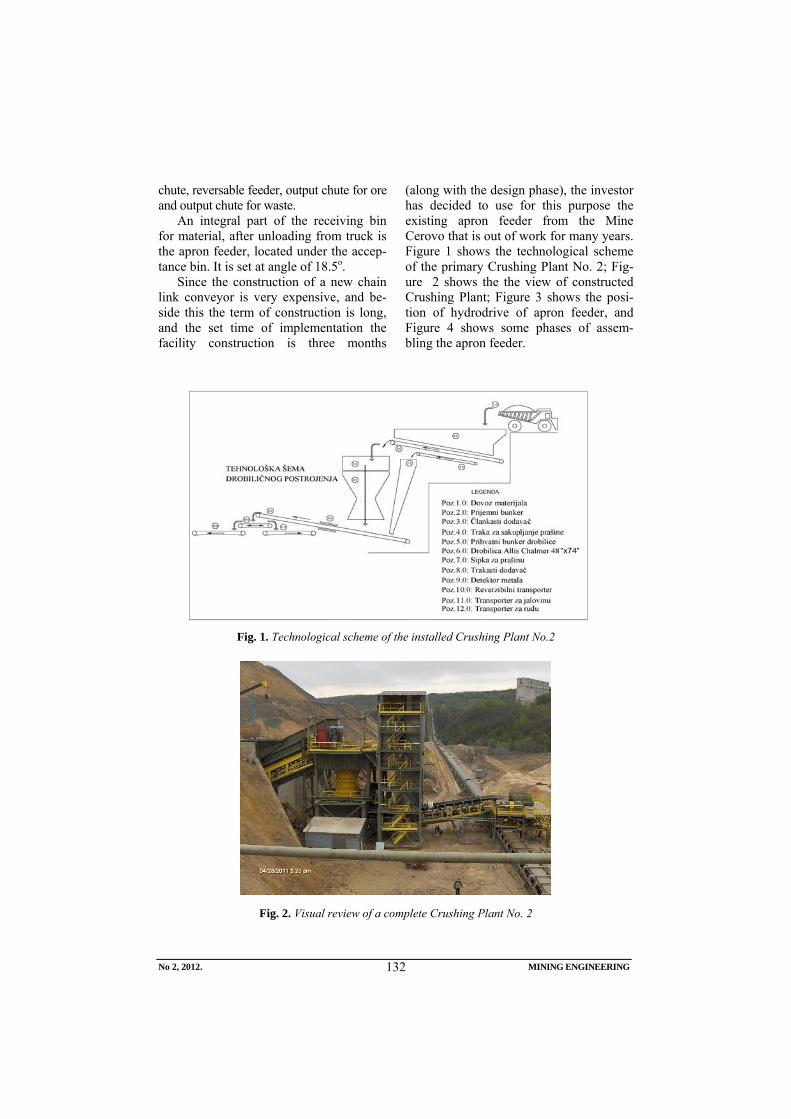
No 2, 2012. MINING ENGINEERING
132
chute, reversable feeder, output chute for ore and output chute for waste.
An integral part of the receiving bin for material, after unloading from truck is the apron feeder, located under the accep-tance bin. It is set at angle of 18.5o.
Since the construction of a new chain link conveyor is very expensive, and be-side this the term of construction is long, and the set time of implementation the facility construction is three months
(along with the design phase), the investor has decided to use for this purpose the existing apron feeder from the Mine Cerovo that is out of work for many years. Figure 1 shows the technological scheme of the primary Crushing Plant No. 2; Fig-ure 2 shows the the view of constructed Crushing Plant; Figure 3 shows the posi-tion of hydrodrive of apron feeder, and Figure 4 shows some phases of assem-bling the apron feeder.
Fig. 1. Technological scheme of the installed Crushing Plant No.2
Fig. 2. Visual review of a complete Crushing Plant No. 2
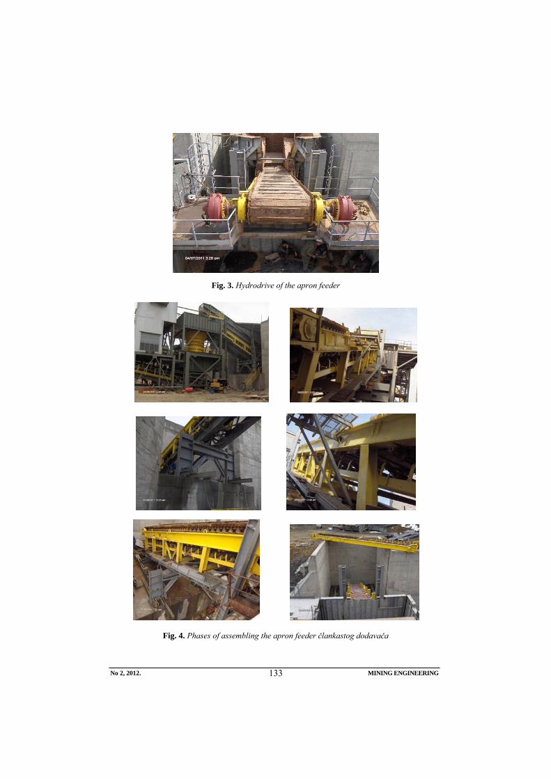
No 2, 2012. MINING ENGINEERING
133
Fig. 3. Hydrodrive of the apron feeder
Fig. 4. Phases of assembling the apron feeder člankastog dodavača
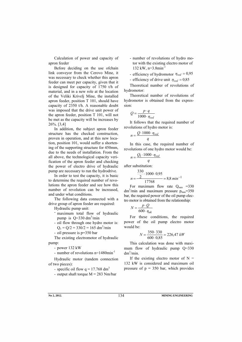
No 2, 2012. MINING ENGINEERING
134
Calculation of power and capacity of apron feeder
Before deciding on the use ofchain link conveyor from the Cerovo Mine, it was necessary to check whether this apron feeder can meet per capacity, given that it is designed for capacity of 1750 t/h of material, and in a new role at the location of the Veliki Krivelj Mine, the installed apron feeder, position T 101, should have capacity of 2350 t/h. A reasonable doubt was imposed that the drive unit power of the apron feeder, position T 101, will not be met as the capacity will be increases by 26%. [3,4]
In addition, the subject apron feeder structure has the checked construction, proven in operation, and at this new loca-tion, position 101, would suffer a shorten-ing of the supporting structure for 450mm, due to the needs of installation. From the all above, the technological capacity veri-fication of the apron feeder and checking the power of electro drive of hydraulic pump are necessary to run the hydrodrive.
In order to test the capacity, it is basic to determine the required number of revo-lutions the apron feeder and see how this number of revolution can be increased, and under what conditions.
The following data connected with a drive group of apron feeder are required:
Hydraulic pump unit: - maximum total flow of hydraulic
pump is Q=330 dm3/min - oil flow through one hydro motor is:
Q1 = Q/2 = 330/2 = 165 dm3/min - oil pressure is p=350 bar The existing electromotor of hydraulic
pump: - power 132 kW - number of revolutions n=1480min-1 Hydraulic motor (tandem connection
of two pieces): - specific oil flow q = 17.768 dm3 - output shaft torque M = 283 Nm/bar
- number of revolutions of hydro mo-tor with the existing electro motor of 132 kW, n=3.8min-1
- efficiency of hydromotor 95,0=volη - efficiency of drive unit 850,vol =η Theoretical number of revolutions of
hydromotor: Theoretical number of revolutions of
hydromotor is obtained from the expres-sion:
volηqpQ⋅⋅
=1000
It follows that the required number of revolutions of hydro motor is:
qηQn vol⋅⋅
=1000
In this case, the required number of revolutions of one hydro motor would be:
qηQn vol⋅⋅
=10001
after substitution:
18817768
95010002
330−=
⋅⋅= min,
,n
For maximum flow rate Qmax =330 dm3/min and maximum pressure pmax=350 bar, the required power of the oil pump elec-tro motor is obtained from the relationship:
ukηQpN⋅⋅
=600
For these conditions, the required power of the oil pump electro motor would be:
kWN 47,22685,0600
330350=
⋅⋅
=
This calculation was done with maxi-mum flow of hydraulic pump Q=330 dm3/min.
If the existing electro motor of N = 132 kW is considered and maximum oil pressure of p = 350 bar, which provides
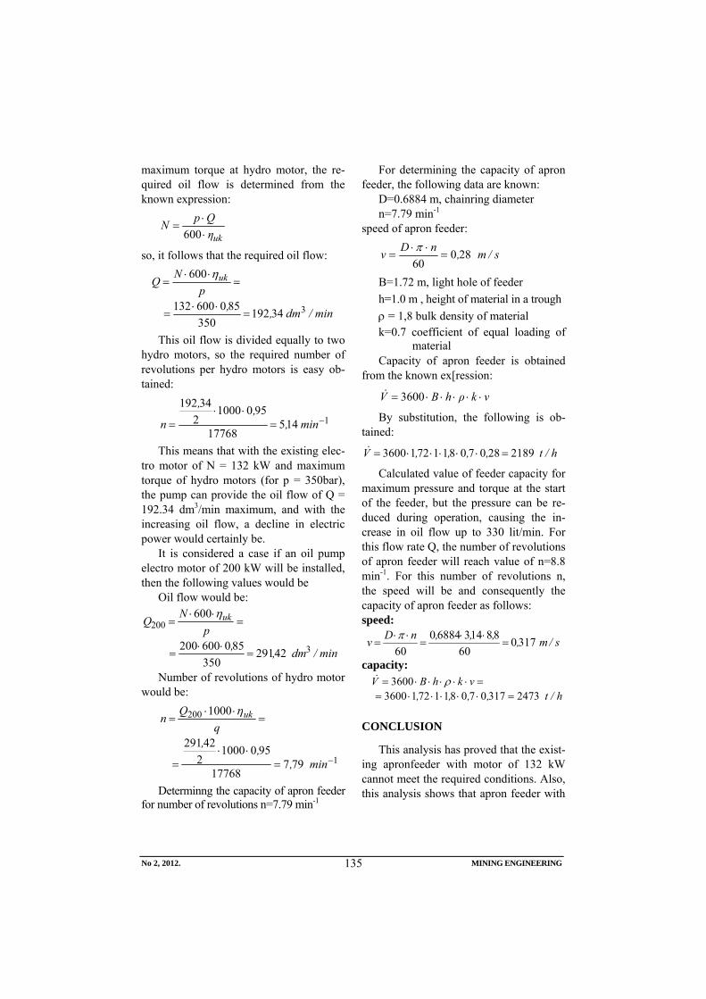
No 2, 2012. MINING ENGINEERING
135
maximum torque at hydro motor, the re-quired oil flow is determined from the known expression:
ukηQpN⋅⋅
=600
so, it follows that the required oil flow:
min/dm,,p
NQ uk
334192350
850600132
600
=⋅⋅
=
=⋅⋅
=η
This oil flow is divided equally to two hydro motors, so the required number of revolutions per hydro motors is easy ob-tained:
114517768
95010002
34192−=
⋅⋅= min,
,,
n
This means that with the existing elec-tro motor of N = 132 kW and maximum torque of hydro motors (for p = 350bar), the pump can provide the oil flow of Q = 192.34 dm3/min maximum, and with the increasing oil flow, a decline in electric power would certainly be.
It is considered a case if an oil pump electro motor of 200 kW will be installed, then the following values would be
Oil flow would be:
min/dm,,p
NQ uk
3
200
42291350
850600200
600
=⋅⋅
=
=⋅⋅
=η
Number of revolutions of hydro motor would be:
1
200
79717768
95010002
42291
1000
−=⋅⋅
=
=⋅⋅
=
min,,,
qQn ukη
Determinng the capacity of apron feeder for number of revolutions n=7.79 min-1
For determining the capacity of apron feeder, the following data are known:
D=0.6884 m, chainring diameter n=7.79 min-1
speed of apron feeder:
s/m,nDv 28060
=⋅⋅
=π
B=1.72 m, light hole of feeder h=1.0 m , height of material in a trough ρ = 1,8 bulk density of material k=0.7 coefficient of equal loading of
material Capacity of apron feeder is obtained
from the known ex[ression:
vkρhBV ⋅⋅⋅⋅⋅= 3600&
By substitution, the following is ob-tained:
h/t,,,,V 2189280708117213600 =⋅⋅⋅⋅⋅=&
Calculated value of feeder capacity for maximum pressure and torque at the start of the feeder, but the pressure can be re-duced during operation, causing the in-crease in oil flow up to 330 lit/min. For this flow rate Q, the number of revolutions of apron feeder will reach value of n=8.8 min-1. For this number of revolutions n, the speed will be and consequently the capacity of apron feeder as follows: speed:
s/m,,,,nDv 317060
881436884060
=⋅⋅
=⋅⋅
=π
capacity:
h/t,,,,vkhBV
247331707081172136003600
=⋅⋅⋅⋅⋅==⋅⋅⋅⋅⋅= ρ&
CONCLUSION
This analysis has proved that the exist-ing apronfeeder with motor of 132 kW cannot meet the required conditions. Also, this analysis shows that apron feeder with
No 2, 2012. MINING ENGINEERING
136
a choice of more powerful 200 kW electro motor can meet the required capacity of 2350 t/h. Other elements of drive unit: oil pump, hydro motors (type Heglund) re-main the same, i.e. the existing ones. Ac-cording to this analysis, the investor has taken all necessary activities to carry out the necessary reconstruction of drive unit of apron feeders and practically use the existing feeder from the Copper Mine Cerovo Cementacija-1, and with very little investment to solve the problem of apron feeder for the Crushing Plant No. 2 at the Open Pit Veliki Krivelj. Exploitation pe-riod of a year back is the best proof that this analysis was correct, because it was proved that the operation of apron feeder, just like the whole subject system [5,6] is a stable, reliable and suitable to the re-quired technological requirements.
REFERENCES
[1] Technological Basis in Designing the Plant for Mineral Processing, Mining Institute, Belgrade, 1999 (in Serbian);
[2] AMP of Increase the Annual Ore Processing in the Veliki Krivelj Flotation Plant to 10.6 million t of Run-of- Mine Ore, Technological Project – Copper Institute Bor, 1997 (in Serbian)
[3] AMP of Copper Ore Mining and Processing in the Deposit Veliki Krivelj for Capacity of 106 x106 t of Wet Ore Annually II, Technical Projects – Part Mining, II.3. Verification the Capacity and Technical-Technological Solution of the Transport System for Waste, Mining and Metallurgy Institute Bor, 2011 (in Serbian);
[4] AMP of Copper Ore Mining and Processing in the Deposit Veliki Krivelj for Capacity of 106 x106 t of Wet Ore Annually III, Technical Project – Part Mineral Processing, III.1.Technical Project of Ore Processing, Mining and Metallurgy Institute Bor, 2011 (in Serbian);
[5] D. Milanović, Z. Marković, N. Magdalinović, R. Jovanović, D. Urošević, Increasing of Annual Crusing and Sieving Capacity of Wet Ore in the Flotation Plant Veliki Krivelj RTB Bor, Proceedings, XIV Balkan Mineral Processing Congress, Volume I, Tuzla, B&H, June 14-16, 2011, pp. 125-132;
[6] D. Milanović, Z. Marković, D. Urošević, M. Ignjatović, System Improvement of Ore Comminuting in the Veliki Krivelj Plant, Mining Engineering, 1/2011, pp. 155-166 .
Broj 2,2012. RUDARSKI RADOVI
137
INSTITUT ZA RUDARSTVO I METALURGIJU BOR YU ISSN: 1451-0162 KOMITET ZA PODZEMNU EKSPLOATACIJU MINERALNIH SIROVINA UDK: 622
UDK: 666.952:546.54:669.015:622.7(045)=861
Branislav Čađenović*, Vesna Marjanović*, Vesna Ljubojev*, Dragan Milanović*
MOGUĆNOST ISKORIŠĆENJA BAKRENCA IZ TOPIONIČKE ŠLJAKE KOD NJENOG DIREKTNOG IZLIVANJA IZ PEĆI**
Izvod
U ovom radu su prikazana labaratorijska ispitivanja uzoraka šljake iz “Depoa šljake 1” koji se nalazi u industrijskom krugu RTB-a Bor. Ispitivanjem je uočeno izdvanjanje bakrenca sa visokim sadržajem bakra, kao i izdvajanje elementarnog bakra. Zbog boljih ekonomskih efekata treba razmotriti mogućnost fizičke metode koncetracije bakrenca na osnovu njegovih fizičko - hemijskih osobina.
Ključne reči: topionička šljaka, bakrenac, bakar, iskorišćenje
*Institut za rudarstvo i metalurgiju Bor **Ovaj rad je proistekao kao rezultat projekta evidencioni broj TR 33023 „Razvoj tehnologija
flotacijske prerade ruda bakra i plemenitih metala radi postizanja boljih tehnoločkih rezultata“ finansiranog od strane Ministarstva prosvete i nauke Republike Srbije.
UVOD
U industrijskom krugu RTB Bor u Boru nalaze četiri deponije topioničke šljake. Najznačajnija i najveća deponija šljake iz plamenih peći je „Depo šljake 1”, gde je šljaka odlagana do 1997. godine. Ova deponija šljake može se posmatrati kao tehnogeno ležište mineralnih sirovina, zbog sadržaja korisnih komponenti i mogućnosti njihove valorizacije.
Na reprezentativnim uzorcima izvr-šenja su mineraloška, strukturna, fizička i hemijska ispitivanja topioničke šljake.
GEOLOSKE KARAKTERISTIKE TEHNOGENOG LEŽIŠTA “DEPO ŠLJAKE 1”
Tehnogeno ležište bakra “Depo šljake 1” je izometričnog oblika, čija duža osa ima orijentaciju SZ-JI i dužinu oko 700 m, a
kraća osa ima orjentaciju JZ-SI i dužinu oko 200 m. U jugoistočnom delu graniči se sa flotacijskim jalovištem, dok se na severozapadu graniči sa tehnogenim ležištem “Depo šljake 4” na kome se, od 1997. godine deponuje topionička šljaka iz plamenih peći. Severoistočnu granicu ležišta čini jalovište površinskog kopa, a jugozapadnu industrijska postrojenja TIR-a (Fabrika sumporne kiseline, topionička postrojenja i termoelektrana), te indu-strijska putna i železnička infrastruktura.
Geološke karakteristike tehnogenog ležišta bakra “Depo šljake 1“ uslovljene su, pre svega, neposrednom podlogom na kojoj su deponovane, kao i načinom obrazovarnja deponije. Podloga deponije najvećim delom je tehnogeni materijal tj. stenska otkrivka sa površinskog kopa,
Broj 2,2012. RUDARSKI RADOVI
138
prethodno deponovaniu u koritu Borske reke, dok su samo malim delom neposredno ispod šljake geogene tvorevine (borski konglomerati, vulkano-klastične stene i aluvion). Deponija je stvarana sukcesivnim izlivanjem užarenog rastopa šljake, pa je u tom pogledu slična izlivima lave.[1]
ŠLJAKA IZ METALURŠKOG PROCESA TOPLJENJA ŠARŽE U TOPIONICI U BORU
Kod svih pirometalurških procesa dobijanja metala (bakra), pored osnovnog produkta (metalnog rastopa), obrazuje se i druga tečna faza (šljaka), koja sadrži nemetalične uključke i novoobrazovane okside, i predstavlja balast prilikom dobijanja čistog metala. Da bi proces dobijanja metala tekao po tehnološkom zahtevu, neophodno je da šljaka ispunjava sledeće uslove:
• šljake moraju imati dobru tečljivost, i • da se dobro odvajaju od metala
(bakrenca) i da dobro rastvaraju razne elemente koji štetno utiču na osobine metala, koji se u procesima dobijaju.
Šljake predstavljaju složene sisteme od većeg broja komponenata, a najčešće su to rastopi različitih oksida sa vrlo visokim temperaturama topljenja.
Sastav šljake veoma utiče na tok samog metalurškog procesa, kao i na kvalitet konačnog proizvoda, pa se zato značaju šljake u metalurgiji sve više posvećuje posebna pažnja.
Za objašnjenje formiranja i strukture metalurških šljaka koristi se molekularna teorija i jonska teorija obrazovanja šljake.
Osnovne komponente šljake prilikom topljenja bakarnog koncentrata su SiO2, FeO, Fe2O3 i MgO. Pored navedenih komponenti šljaka često sadrži Fe3O4, Al2O3, Cu2S, i skoro redovno sitne kapljice mehanički zahvaćenog bakrenca.
Jedinjenje FeO u šljaci se najčešće nalazi u obliku fajalita (FeO)2·SiO2, ali u fajalitu može biti rastvoren i višak gvožđe-oksida, kao što je slučaj u baznim šljakama.
Fajalit (Fe2SiO4) pripada grupi olivina koji kristališu rombično u obliku kratkostubičastih kristala ili se pojavljuju u zrnastim agregatima. Najčešće imaju karakterističnu maslinastozelenu boju po kojoj su i dobili ime, ali mogu biti i različito obojeni od bele, svetlozelene, preko maslinaste i tamnozelene, do crne. Staklaste su sjajnosti ili masne na prelomima. Gotovo su bez cepljivosti, tvrdine 6,5-7.[4]
Šljake plamene peći prema svom hemijskom sastavu i stvarnoj rastvorljivosti bakrenca u njima, u stanju ravnoteže, trebalo bi da sadrže 0,15 do 0,25 % bakra.
To se međutim ne postiže u prvenstveno zbog značajnog prisustva mehanički uključenog bakrenca u šljakama, kao i zbog hemijski vezanog bakra u obliku oksida u slučaju kada se topi prženac.
LABARATORIJSKA ISPITIVANJA
Na pet reprezativnih uzoraka šljake izvršene su minerološke i labaratorijske analize. Hemijski sastav uzoraka šljake dat je u tabeli 1., a hemijski sastav reprezan-tativnog uzorka šljake dat je u tabeli 2.
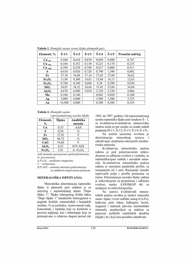
Broj 2,2012. RUDARSKI RADOVI
139
Tabela 1. Hemijski sastav rovne šljake plamenih peći
Elementi, % Š-1/1 Š-1/2 Š-1/3 Š-1/4 Š-1/5 Prosečni sadržaj
Cu uk. 0,560 0,610 0,870 0,850 0,980 0,747 Cu oks. 0,166 0,352 0,130 0,223 0,178 0,233 Cu sulf. 0,394 0,258 0,740 0,617 0,800 0,511
S 0,610 0,920 0,720 0,790 1,390 0,892 Fe 37,70 34,98 37,14 37,05 37,89 36,62
Fe2O3 11,98 9,300 14,01 15,04 16,13 12,63 Fe3O4 8,760 8,540 9,680 9,38 9,290 9,030 SiO2 34,03 34,52 34,66 33,45 33,04 34,04 Al2O3 4,670 6,080 5,010 3,230 5,330 5,066 Mo 0,160 0,140 0,042 0,020 0,100 Ag 3,000 4,900 3,500 3,500 3,725 Au <0,500 0,800 0,500 0,300 0,525
Tabela 2. Hemijski sastav reprezentativnog uzorka šljake
Elementi, %
Šljaka Analitička metoda
Cu 0,33 AAS S 0,20 G
Fe 27,92 V SiO2 46,72 G CaO 19,60 V Al2O3 4,52 ICP-AES Fe3O4 3,41 A- Fe3O4
AAS-atomska apsorpciona spektrofotometrija, G- gravimetrija, A-Fe3O4 – analizator magnetita, V – volumetrija, ICP-AES – atomska emisiona spektrometrija
sa induktivno kuplovanom plazmom.
MINERALOŠKA ISPITIVANJA
Mineraloška determinacija topioničke šljake iz plamenih peći urađena je sa najvećeg i najznačajnijeg depoa “Depo šljake 1”. Šljaku tehnogenog ležišta bakra “Depo šljake 1” karakteriše heterogenost u pogledu fizičkih, mineraloških i hemijskih osobina. To je posledica raznovrsnosti ruda, koncentrata i topitelja koji su korišćeni u procesu topljenja, kao i tehnologije koje su primenjivane u relativno dugom period (do
1943. do 1997. godine). Od reprezentativnog uzorka topioničke šljake pod oznakom Š - 1, za kvalitativno-kvantitativnu minera-lošku analizu uzeta su pet uzorka za izradu rudnih preparata (Š-1/1, Š-1/2, Š-1/3, Š-1/4, Š-1/5).
Na uzetim uzorcima izvršena je determinacija mineralnog sastava i određivanje strukturno-teksturnih karakte-ristika minerala.
Kvalitativna mineraloška analiza rađena je pod polarizacionim mikro-skopom za odbijenu svetlost u vazduhu, sa indentifikacijom rudnih i nerudnih mine-rala. Kvantitativna mineraloška analiza rađena je metodom paralelnih profila, sa rastojanjem od 1 mm. Rastojanje između ispitivanih polja i profila pomerana su ručno. Determinacja uzoraka šljake rađena je mikroskopom za propuštenu i odbijenu svetlost, marke AXIOSKOP 40, sa uređajem za mikrofotografiju.
Na osnovu kvalitativnih minera-loških analiza utvrđen je sledeći mineralni sastav šljake: čvrsti sulfidni rastop (Cu-Fe), halkozin, pirit, bakar, halkopirit, bornit, magnetit i minerali jalovine (nemetalidni minerali), predstavljeni su staklom sa pojavom razllčitih eutekličkih dendrita (fajalit i dr.) koji nisu posebno određivani.
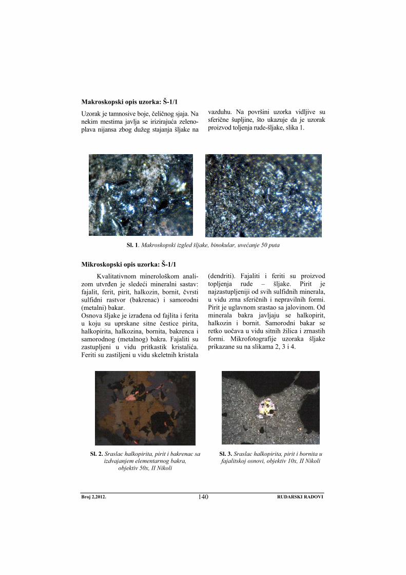
Broj 2,2012. RUDARSKI RADOVI
140
Makroskopski opis uzorka: Š-1/1
Uzorak je tamnosive boje, čeličnog sjaja. Na nekim mestima javlja se irizirajuća zeleno-plava nijansa zbog dužeg stajanja šljake na
vazduhu. Na površini uzorka vidljive su sferične šupljine, što ukazuje da je uzorak proizvod toljenja rude-šljake, slika 1.
Sl. 1. Makroskopski izgled šljake, binokular, uvećanje 50 puta
Mikroskopski opis uzorka: Š-1/1
Kvalitativnom minerološkom anali-zom utvrđen je sledeći mineralni sastav: fajalit, ferit, pirit, halkozin, bornit, čvrsti sulfidni rastvor (bakrenac) i samorodni (metalni) bakar. Osnova šljake je izrađena od fajlita i ferita u koju su uprskane sitne čestice pirita, halkopirita, halkozina, bornita, bakrenca i samorodnog (metalnog) bakra. Fajaliti su zastupljeni u vidu pritkastik kristalića. Feriti su zastiljeni u vidu skeletnih kristala
(dendriti). Fajaliti i feriti su proizvod topljenja rude – šljake. Pirit je najzastupljeniji od svih sulfidnih minerala, u vidu zrna sferičnih i nepravilnih formi. Pirit je uglavnom srastao sa jalovinom. Od minerala bakra javljaju se halkopirit, halkozin i bornit. Samorodni bakar se retko uočava u vidu sitnih žilica i zrnastih formi. Mikrofotografije uzoraka šljake prikazane su na slikama 2, 3 i 4.
Sl. 2. Sraslac halkopirita, pirit i bakrenac sa izdvajanjem elementarnog bakra,
objektiv 50x, II Nikoli
Sl. 3. Sraslac halkopirita, pirit i bornita u fajalitskoj osnovi, objektiv 10x, II Nikoli
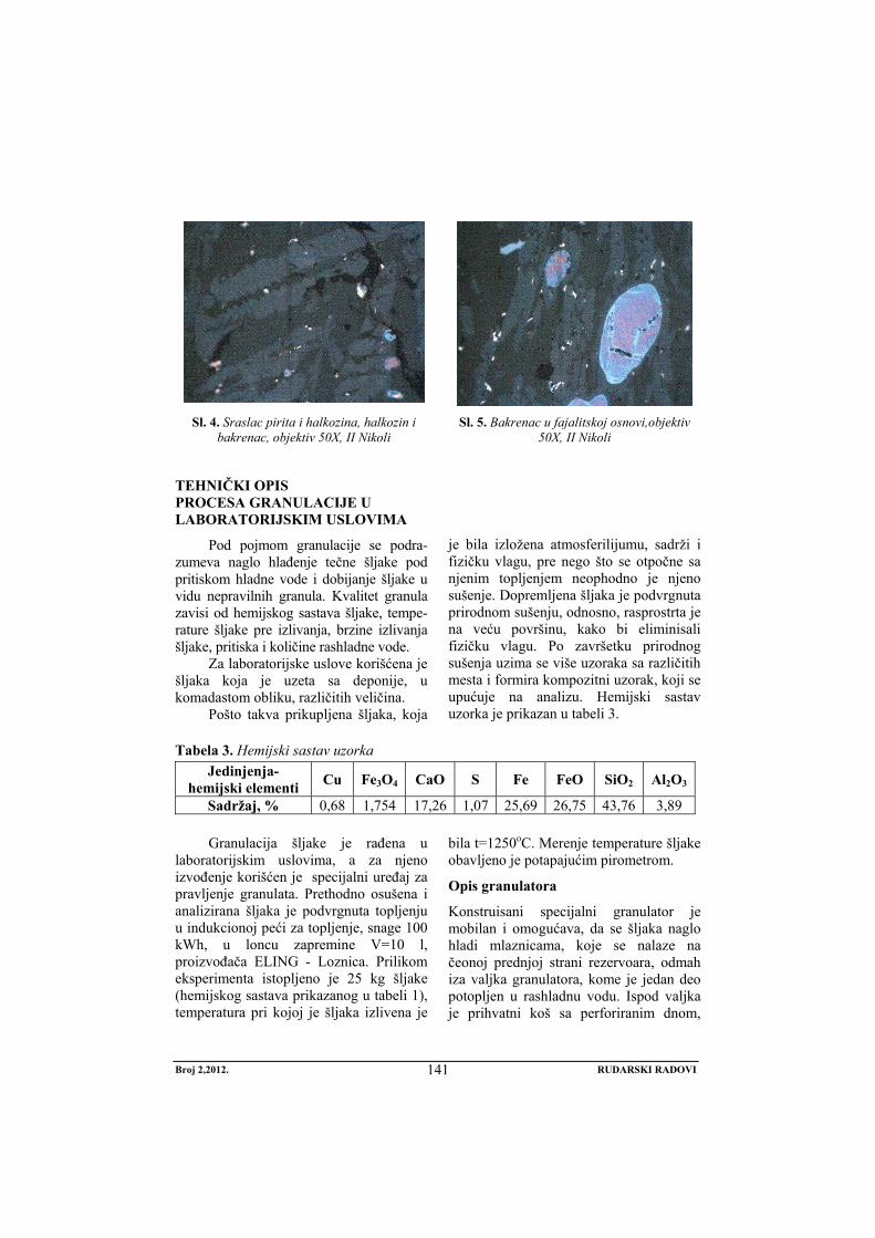
Broj 2,2012. RUDARSKI RADOVI
141
Sl. 4. Sraslac pirita i halkozina, halkozin i
bakrenac, objektiv 50X, II Nikoli Sl. 5. Bakrenac u fajalitskoj osnovi,objektiv
50X, II Nikoli
TEHNIČKI OPIS PROCESA GRANULACIJE U LABORATORIJSKIM USLOVIMA
Pod pojmom granulacije se podra-zumeva naglo hlađenje tečne šljake pod pritiskom hladne vode i dobijanje šljake u vidu nepravilnih granula. Kvalitet granula zavisi od hemijskog sastava šljake, tempe-rature šljake pre izlivanja, brzine izlivanja šljake, pritiska i količine rashladne vode.
Za laboratorijske uslove korišćena je šljaka koja je uzeta sa deponije, u komadastom obliku, različitih veličina.
Pošto takva prikupljena šljaka, koja
je bila izložena atmosferilijumu, sadrži i fizičku vlagu, pre nego što se otpočne sa njenim topljenjem neophodno je njeno sušenje. Dopremljena šljaka je podvrgnuta prirodnom sušenju, odnosno, rasprostrta je na veću površinu, kako bi eliminisali fizičku vlagu. Po završetku prirodnog sušenja uzima se više uzoraka sa različitih mesta i formira kompozitni uzorak, koji se upućuje na analizu. Hemijski sastav uzorka je prikazan u tabeli 3.
Tabela 3. Hemijski sastav uzorka
Jedinjenja- hemijski elementi Cu Fe3O4 CaO S Fe FeO SiO2 Al2O3
Sadržaj, % 0,68 1,754 17,26 1,07 25,69 26,75 43,76 3,89
Granulacija šljake je rađena u laboratorijskim uslovima, a za njeno izvođenje korišćen je specijalni uređaj za pravljenje granulata. Prethodno osušena i analizirana šljaka je podvrgnuta topljenju u indukcionoj peći za topljenje, snage 100 kWh, u loncu zapremine V=10 l, proizvođača ELING - Loznica. Prilikom eksperimenta istopljeno je 25 kg šljake (hemijskog sastava prikazanog u tabeli 1), temperatura pri kojoj je šljaka izlivena je
bila t=1250oC. Merenje temperature šljake obavljeno je potapajućim pirometrom.
Opis granulatora
Konstruisani specijalni granulator je mobilan i omogućava, da se šljaka naglo hladi mlaznicama, koje se nalaze na čeonoj prednjoj strani rezervoara, odmah iza valjka granulatora, kome je jedan deo potopljen u rashladnu vodu. Ispod valjka je prihvatni koš sa perforiranim dnom,
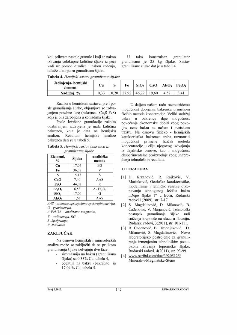
Broj 2,2012. RUDARSKI RADOVI
142
koji prihvata nastale granule i koji se nakon izlivanja celokupne količine šljake iz peći vadi uz pomoć dizalice i nakon ceđenja, odlaže u korpu za granulisanu šljaku.
U tako konstruisan granulator granulisano je 25 kg šljake. Sastav granulisane šljake dat je u tabeli 4.
Tabela 4. Hemijski sastav granulisane šljake
Jedinjenja- hemijski elementi Cu S Fe SiO2 CaO Al2O3 Fe3O4
Sadržaj, % 0,33 0,20 27,92 46,72 19,60 4,52 3,41
Razlika u hemiskom sastavu, pre i po-sle granulisanja šljake, objašnjava se izdva-janjem posebne faze (bakrenca- Cu2S FeS) koja je bila zarobljena u komadima šljake.
Posle izvršene granulacije ručnim odabiranjem izdvojena je mala količina bakrenca, koja je data na hemijsku analizu. Rezultati hemijske analize bakrenca dati su u tabeli 5. Tabela 5. Hemijski sastav bakrenca iz
granulisane šljake Elementi,
% Šljaka Analitička metoda
Cu 17,04 EG Fe 36,38 V S 15,13 S
CaO 7,40 AAS FeO 44,02 R
Fe3O4 6,53 A- Fe3O4 SiO2 17,00 G Al2O3 1,63 AAS
AAS - atomska apsorpciona spektrofotometrija, G - gravimetrija, A-Fe3O4 – analizator magnetita, V – volimetrija, EG - , S -Spaljivanje, R -Računski
ZAKLJUČAK
Na osnovu hemijskih i mineroloških analiza može se zaključiti da se prilikom granulisanja šljake izdvajuju dve faze:
- siromašnija na bakru (granulisana šljaka) sa 0,33% Cu, tabela 4,
- bogatija na bakru (bakrenac) sa 17,04 % Cu, tabela 5.
U daljem našem radu razmotrićemo mogućnost dobijanja bakrenca primenom fizičih metoda koncetracije. Veliki sadržaj bakra u bakrencu daje mogućnost povećanja ekonomske dobiti zbog povo-ljne cene bakra na našem i svetskom tržištu. Na osnovu fizičko - hemijskih karakteristika bakrenca treba razmotriti mogućnost primene fizičih metoda koncentracije u cilju njegovog izdvajanja iz fajalitske osnove, kao i mogućnost eksperimentalne proizvodnje zbog unapre-đenja tehnoloških rezultata.
LITERATURA
[1] D. Kržanović, R. Rajković, V. Marinković, Geološke karakteristike, modeliranje i tehničko rešenje otko-pavanja tehnogenog ležišta bakra „Depo šljake 1“ u Boru, Rudarski radovi 1(2009), str. 7-17
[2] S. Magdalinović, D. Milanović, B. Čađenović, V. Marjanović: Tehnološki postupak granuliranja šljake radi sniženja krupnoće na ulazu u flotaciju, Rudarski radovi, 3(2011), str. 101-111.
[3] B. Čađenović, B. Drobnjaković, D. Milanović, S. Magdalinović, Novo laboratorijsko postrojenje za granuli-ranje izmenjenim tehnološkim postu-pkom izlivanja topioničke šljake, Rudarski radovi, 4(2011), str. 93-99.
[4] www.scribd.com/doc/39205125/ Minerali-i-Magmatske-Stene
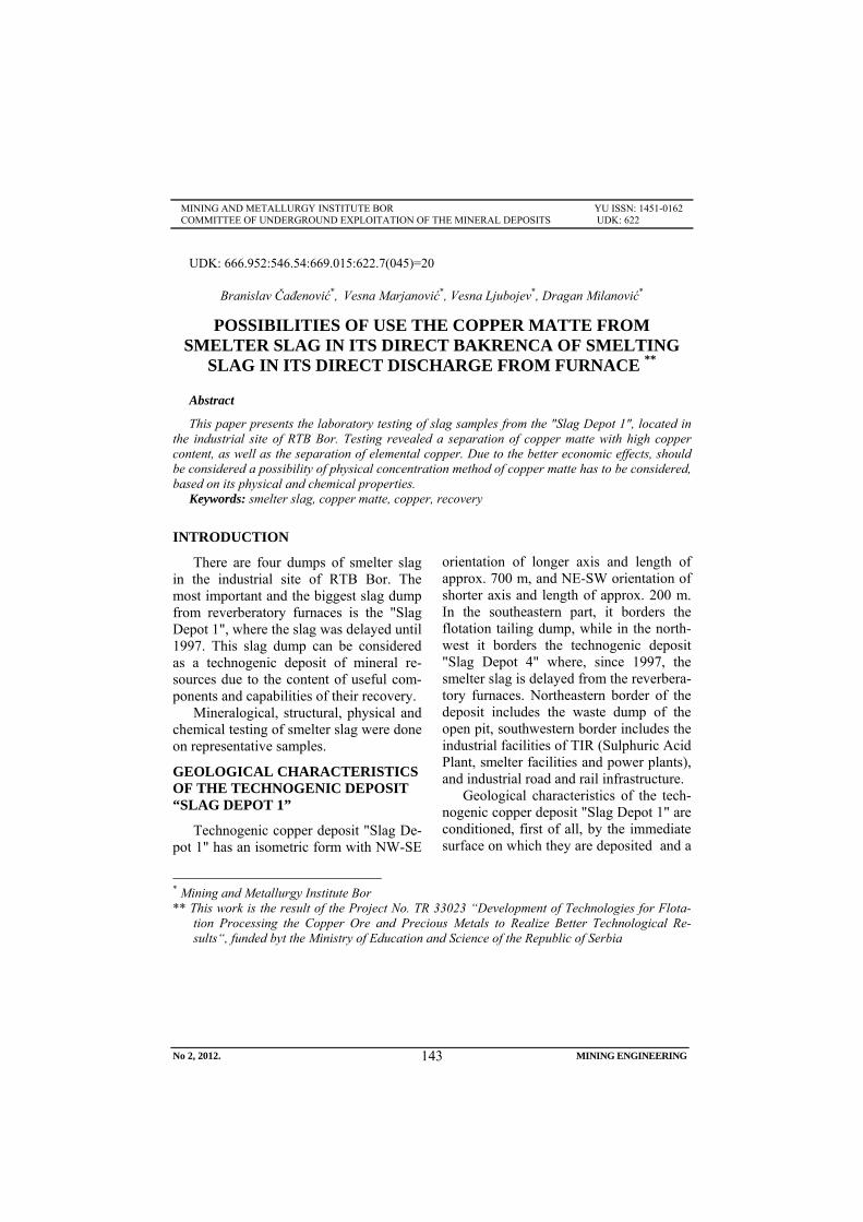
No 2, 2012. MINING ENGINEERING
143
MINING AND METALLURGY INSTITUTE BOR YU ISSN: 1451-0162 COMMITTEE OF UNDERGROUND EXPLOITATION OF THE MINERAL DEPOSITS UDK: 622
UDK: 666.952:546.54:669.015:622.7(045)=20
Branislav Čađenović*, Vesna Marjanović*, Vesna Ljubojev*, Dragan Milanović*
POSSIBILITIES OF USE THE COPPER MATTE FROM SMELTER SLAG IN ITS DIRECT BAKRENCA OF SMELTING
SLAG IN ITS DIRECT DISCHARGE FROM FURNACE **
Abstract
This paper presents the laboratory testing of slag samples from the "Slag Depot 1", located in the industrial site of RTB Bor. Testing revealed a separation of copper matte with high copper content, as well as the separation of elemental copper. Due to the better economic effects, should be considered a possibility of physical concentration method of copper matte has to be considered, based on its physical and chemical properties.
Keywords: smelter slag, copper matte, copper, recovery
* Mining and Metallurgy Institute Bor ** This work is the result of the Project No. TR 33023 “Development of Technologies for Flota-
tion Processing the Copper Ore and Precious Metals to Realize Better Technological Re-sults“, funded byt the Ministry of Education and Science of the Republic of Serbia
INTRODUCTION
There are four dumps of smelter slag in the industrial site of RTB Bor. The most important and the biggest slag dump from reverberatory furnaces is the "Slag Depot 1", where the slag was delayed until 1997. This slag dump can be considered as a technogenic deposit of mineral re-sources due to the content of useful com-ponents and capabilities of their recovery.
Mineralogical, structural, physical and chemical testing of smelter slag were done on representative samples.
GEOLOGICAL CHARACTERISTICS OF THE TECHNOGENIC DEPOSIT “SLAG DEPOT 1”
Technogenic copper deposit "Slag De-pot 1" has an isometric form with NW-SE
orientation of longer axis and length of approx. 700 m, and NE-SW orientation of shorter axis and length of approx. 200 m. In the southeastern part, it borders the flotation tailing dump, while in the north-west it borders the technogenic deposit "Slag Depot 4" where, since 1997, the smelter slag is delayed from the reverbera-tory furnaces. Northeastern border of the deposit includes the waste dump of the open pit, southwestern border includes the industrial facilities of TIR (Sulphuric Acid Plant, smelter facilities and power plants), and industrial road and rail infrastructure.
Geological characteristics of the tech-nogenic copper deposit "Slag Depot 1" are conditioned, first of all, by the immediate surface on which they are deposited and a
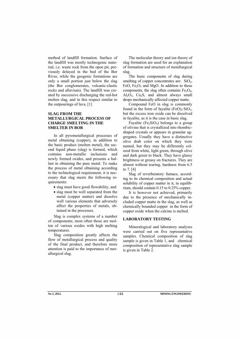
No 2, 2012. MINING ENGINEERING
144
method of landfill formation. Surface of the landfill was mostly technogenic mate-rial, i.e. waste rock from the open pit, pre-viously delayed in the bed of the Bor River, while the geogenic formations are only a small portion just below the slag (the Bor conglomerates, volcanic-clastic rocks and alluvium). The landfill was cre-ated by successive discharging the red-hot molten slag, and in this respect similar to the outpourings of lava. [1]
SLAG FROM THE METALLURGICAL PROCESS OF CHARGE SMELTING IN THE SMELTER IN BOR
In all pyrometallurgical processes of metal obtaining (copper), in addition to the basic product (molten metal), the sec-ond liquid phase (slag) is formed, which contains non-metallic inclusions and newly formed oxides, and presents a bal-last in obtaining the pure metal. To make the process of metal obtaining according to the technological requirement, it is nec-essary that slag meets the following re-quirements:
• slag must have good flowability, and • slag must be well separated from the
metal (copper matter) and dissolve well various elements that adversely affect the properties of metals, ob-tained in the processes.
Slag is complex systems of a number of components; most often those are mol-ten of various oxides with high melting temperatures.
Slag composition greatly affects the flow of metallurgical process and quality of the final product, and therefore more attention is paid to the importance of met-allurgical slag.
The molecular theory and ion theory of slag formation are used for an explanation of formation and structure of metallurgical slag.
The basic components of slag during smelting of copper concentrates are: SiO2, FeO, Fe2O3 and MgO. In addition to these components, the slag often contains Fe3O4, Al2O3, Cu2S, and almost always small drops mechanically affected copper matte.
Compound FeO in slag is commonly found in the form of fayalite (FeO)2·SiO2, but the excess iron oxide can be dissolved in fayalite, as it is the case in basic slag.
Fayalite (Fe2SiO4) belongs to a group of olivine that is crystallized into rhombic-shaped crystals or appears in granular ag-gregates. Usually they have a distinctive olive drab color on which they were named, but they may be differently col-ored from white, light green, through olive and dark green to black. They have glassy brightness or greasy on fractures. They are almost without tearing, hardness from 6.5 to 7. [4]
Slag of reverberatory furnace, accord-ing to its chemical composition and actual solubility of copper matter in it, in equilib-rium, should contain 0.15 to 0.25% copper.
It is however not achieved, primarily due to the presence of mechanically in-cluded copper matte in the slag, as well as chemically bounded copper in the form of copper oxide when the calcine is melted.
LABORATORY TESTING
Mineralogical and laboratory analyses were carried out on five representative samples. Chemical composition of slag sample is given in Table 1, and chemical composition of representative slag sample is given in Table 2.
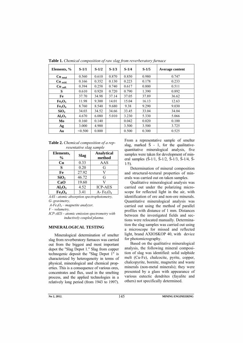
No 2, 2012. MINING ENGINEERING
145
Table 1. Chemical composition of raw slag from reverberatory furnace
Elements, % S-1/1 S-1/2 S-1/3 S-1/4 S-1/5 Average content
Cu total 0.560 0.610 0.870 0.850 0.980 0.747 Cu oxid. 0.166 0.352 0.130 0.223 0.178 0.233 Cu sulf. 0.394 0.258 0.740 0.617 0.800 0.511
S 0.610 0.920 0.720 0.790 1.390 0.892 Fe 37.70 34.98 37.14 37.05 37.89 36.62
Fe2O3 11.98 9.300 14.01 15.04 16.13 12.63 Fe3O4 8.760 8.540 9.680 9.38 9.290 9.030 SiO2 34.03 34.52 34.66 33.45 33.04 34.04
Al2O3 4.670 6.080 5.010 3.230 5.330 5.066 Mo 0.160 0.140 0.042 0.020 0.100 Ag 3.000 4.900 3.500 3.500 3.725 Au <0.500 0.800 0.500 0.300 0.525
Table 2. Chemical composition of a rep-resentative slag sample
Elements, % Slag Analytical
method Cu 0.33 AAS S 0.20 G
Fe 27.92 V SiO2 46.72 G CaO 19.60 V Al2O3 4.52 ICP-AES Fe3O4 3.41 A- Fe3O4
AAS - atomic absorption spectrophotometry, G- gravimetry, A-Fe3O4 – magnetite analyzer, V – volumetry, ICP-AES – atomic emission spectrometry with
inductively coupled plasma.
MINERALOGICAL TESTING
Mineralogical determination of smelter slag from reverberatory furnaces was carried out from the biggest and most important depot the "Slag Depot 1." Slag from copper technogenic deposit the "Slag Depot 1" is characterized by heterogeneity in terms of physical, mineralogical and chemical prop-erties. This is a consequence of various ores, concentrates and flux, used in the smelting process, and the applied technologies in a relatively long period (from 1943 to 1997).
From a representative sample of smelter slag, marked Š - 1, for the qualitative-quantitative mineralogical analysis, five samples were taken for development of min-eral samples (Š-1/1, Š-1/2, Š-1/3, Š-1/4, Š-1/5).
Determination of mineral composition and structural-textural properties of min-erals was carried out on taken samples.
Qualitative mineralogical analysis was carried out under the polarizing micro-scope for reflected light in the air, with identification of ore and non-ore minerals. Quantitative mineralogical analysis was carried out using the method of parallel profiles with distance of 1 mm. Distances between the investigated fields and sec-tions were relocated manually. Determina-tion the slag samples was carried out using a microscope for missed and reflected light, brand AXIOSKOP 40, with device for photomicrography.
Based on the qualitative mineralogical analysis, the following mineral composi-tion of slag was identified: solid sulphide melt (Cu-Fe), chalcocite, pyrite, copper, chalcopyrite, bornite, magnetite and waste minerals (non-metal minerals); they were presented by a glass with appearance of various eutectic dendrites (fayalite and others) not specifically determined.
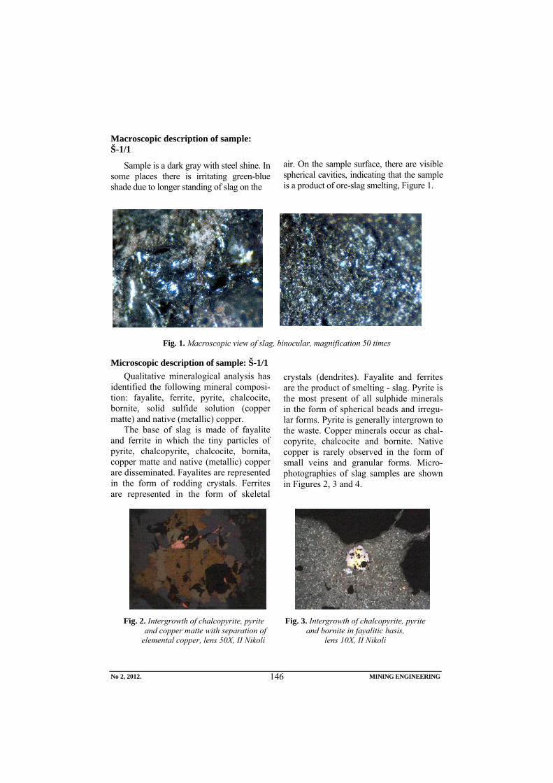
No 2, 2012. MINING ENGINEERING
146
Macroscopic description of sample: Š-1/1
Sample is a dark gray with steel shine. In some places there is irritating green-blue shade due to longer standing of slag on the
air. On the sample surface, there are visible spherical cavities, indicating that the sample is a product of ore-slag smelting, Figure 1.
Fig. 1. Macroscopic view of slag, binocular, magnification 50 times
Microscopic description of sample: Š-1/1 Qualitative mineralogical analysis has
identified the following mineral composi-tion: fayalite, ferrite, pyrite, chalcocite, bornite, solid sulfide solution (copper matte) and native (metallic) copper.
The base of slag is made of fayalite and ferrite in which the tiny particles of pyrite, chalcopyrite, chalcocite, bornita, copper matte and native (metallic) copper are disseminated. Fayalites are represented in the form of rodding crystals. Ferrites are represented in the form of skeletal
crystals (dendrites). Fayalite and ferrites are the product of smelting - slag. Pyrite is the most present of all sulphide minerals in the form of spherical beads and irregu-lar forms. Pyrite is generally intergrown to the waste. Copper minerals occur as chal-copyrite, chalcocite and bornite. Native copper is rarely observed in the form of small veins and granular forms. Micro-photographies of slag samples are shown in Figures 2, 3 and 4.
Fig. 2. Intergrowth of chalcopyrite, pyrite and copper matte with separation of elemental copper, lens 50X, II Nikoli
Fig. 3. Intergrowth of chalcopyrite, pyrite and bornite in fayalitic basis,
lens 10X, II Nikoli
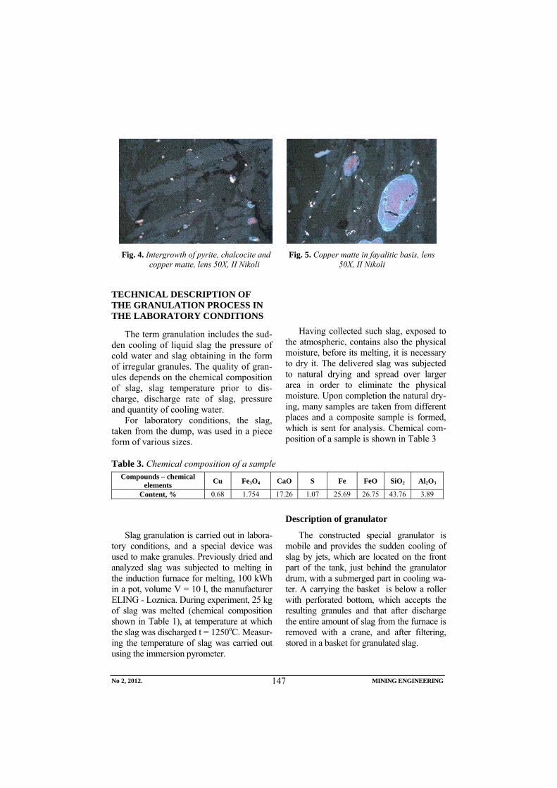
No 2, 2012. MINING ENGINEERING
147
Fig. 4. Intergrowth of pyrite, chalcocite and
copper matte, lens 50X, II Nikoli Fig. 5. Copper matte in fayalitic basis, lens
50X, II Nikoli
TECHNICAL DESCRIPTION OF THE GRANULATION PROCESS IN THE LABORATORY CONDITIONS
The term granulation includes the sud-den cooling of liquid slag the pressure of cold water and slag obtaining in the form of irregular granules. The quality of gran-ules depends on the chemical composition of slag, slag temperature prior to dis-charge, discharge rate of slag, pressure and quantity of cooling water.
For laboratory conditions, the slag, taken from the dump, was used in a piece form of various sizes.
Having collected such slag, exposed to
the atmospheric, contains also the physical moisture, before its melting, it is necessary to dry it. The delivered slag was subjected to natural drying and spread over larger area in order to eliminate the physical moisture. Upon completion the natural dry-ing, many samples are taken from different places and a composite sample is formed, which is sent for analysis. Chemical com-position of a sample is shown in Table 3
Table 3. Chemical composition of a sample Compounds – chemical
elements Cu Fe3O4 CaO S Fe FeO SiO2 Al2O3
Content, % 0.68 1.754 17.26 1.07 25.69 26.75 43.76 3.89
Slag granulation is carried out in labora-tory conditions, and a special device was used to make granules. Previously dried and analyzed slag was subjected to melting in the induction furnace for melting, 100 kWh in a pot, volume V = 10 l, the manufacturer ELING - Loznica. During experiment, 25 kg of slag was melted (chemical composition shown in Table 1), at temperature at which the slag was discharged t = 1250oC. Measur-ing the temperature of slag was carried out using the immersion pyrometer.
Description of granulator
The constructed special granulator is mobile and provides the sudden cooling of slag by jets, which are located on the front part of the tank, just behind the granulator drum, with a submerged part in cooling wa-ter. A carrying the basket is below a roller with perforated bottom, which accepts the resulting granules and that after discharge the entire amount of slag from the furnace is removed with a crane, and after filtering, stored in a basket for granulated slag.
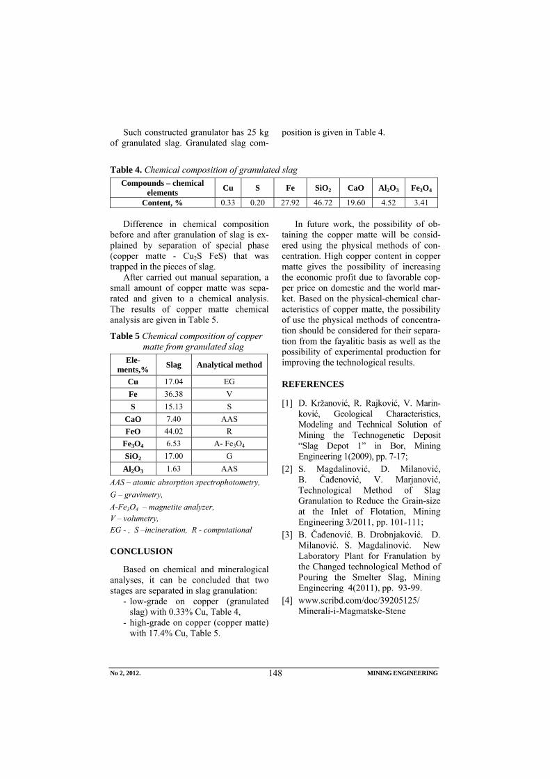
No 2, 2012. MINING ENGINEERING
148
Such constructed granulator has 25 kg of granulated slag. Granulated slag com-
position is given in Table 4.
Table 4. Chemical composition of granulated slag Compounds – chemical
elements Cu S Fe SiO2 CaO Al2O3 Fe3O4
Content, % 0.33 0.20 27.92 46.72 19.60 4.52 3.41
Difference in chemical composition before and after granulation of slag is ex-plained by separation of special phase (copper matte - Cu2S FeS) that was trapped in the pieces of slag.
After carried out manual separation, a small amount of copper matte was sepa-rated and given to a chemical analysis. The results of copper matte chemical analysis are given in Table 5.
Table 5 Chemical composition of copper matte from granulated slag
Ele-ments,% Slag Analytical method
Cu 17.04 EG Fe 36.38 V S 15.13 S
CaO 7.40 AAS FeO 44.02 R
Fe3O4 6.53 A- Fe3O4 SiO2 17.00 G
Al2O3 1.63 AAS AAS – atomic absorption spectrophotometry, G – gravimetry, A-Fe3O4 – magnetite analyzer, V – volumetry, EG - , S –incineration, R - computational
CONCLUSION
Based on chemical and mineralogical analyses, it can be concluded that two stages are separated in slag granulation:
- low-grade on copper (granulated slag) with 0.33% Cu, Table 4,
- high-grade on copper (copper matte) with 17.4% Cu, Table 5.
In future work, the possibility of ob-taining the copper matte will be consid-ered using the physical methods of con-centration. High copper content in copper matte gives the possibility of increasing the economic profit due to favorable cop-per price on domestic and the world mar-ket. Based on the physical-chemical char-acteristics of copper matte, the possibility of use the physical methods of concentra-tion should be considered for their separa-tion from the fayalitic basis as well as the possibility of experimental production for improving the technological results.
REFERENCES
[1] D. Kržanović, R. Rajković, V. Marin-ković, Geological Characteristics, Modeling and Technical Solution of Mining the Technogenetic Deposit “Slag Depot 1” in Bor, Mining Engineering 1(2009), pp. 7-17;
[2] S. Magdalinović, D. Milanović, B. Čađenović, V. Marjanović, Technological Method of Slag Granulation to Reduce the Grain-size at the Inlet of Flotation, Mining Engineering 3/2011, pp. 101-111;
[3] B. Čađenović. B. Drobnjaković. D. Milanović. S. Magdalinović. New Laboratory Plant for Franulation by the Changed technological Method of Pouring the Smelter Slag, Mining Engineering 4(2011), pp. 93-99.
[4] www.scribd.com/doc/39205125/ Minerali-i-Magmatske-Stene
Broj 2,2012. RUDARSKI RADOVI
149
INSTITUT ZA RUDARSTVO I METALURGIJU BOR YU ISSN: 1451-0162 KOMITET ZA PODZEMNU EKSPLOATACIJU MINERALNIH SIROVINA UDK: 622
UDK: 622:338.93:330.1(045)=861
Ljiljana Savić∗, Vladimir Radovanović∗∗, Ljubinko Savić*, Radiša Janković∗∗∗
FAKTORI EKONOMSKE USPEŠNOSTI U RUDNICIMA****
Izvod
Upravljačke odluke u rudarskim preduzećima zasnivaju se na mogućnostima regulisanja tokova poslovanja u pojedinim segmentima ciklusa reprodukcije. Pri tome, uočavaju se i određena objektivna dejstva koje preduzeće svojim upravljačkim merama ne može da otklanja i menja u toku procesa reprodukcije. Određena subjektivna dejstva na poslovanje mezoekonomskog sistema podložna su promenama upravljačkim odnosima.
U ovom radu biće analizirani objektivno uslovljeni faktori ekonomske uspešnosti u rudnicima. U grupu dejstava na poslovanje mezoekonomskog sistema koja su objektivno data mogu se svrstati: prirodni, društveni i tehnički faktori. Prirodni faktori se javljaju kao specifična dejstva čiji se uticaj na preduzeće ne može menjati organizacionim merama ali se može racionalnim po-našanjem preduzeća u korišćenju prirodnih uslova obezbediti njihovo očuvanje. Bogatiji prirodni resursi su u dobroj meri već iscrpljeni, pa su preduzeća iz ove oblasti prinuđena da eksploatišu manje kvalitetne izvore, a to će imati za posledicu poskupljenje proizvodnje. Uticaj društvenih i tehničkih faktora u rudnicima može se menjati, ali ne u toku reprodukcije, već na osnovu opštih promena u privrednom i društvenom okruženju kao i promenom proizvodne snage rada za koju je potrebno dodatno ulaganje iz prethodne akumulacije.
Ključne reči: ekonomska uspešnost, rudarska preduzeća, objektivni faktori, reprodukcija.
∗ FTN K. Mitrovica, [email protected] ∗∗ FTN Čačak, [email protected] ∗∗∗ JPPK Kosovo Obilić, [email protected] **** Ovaj rad je proistekao kao rezultat projekta TR 33045, „Optimizacija pripreme PK prlovi u
rudniku flotacije“, finansiranog od strane Ministarstva prosvete i nauke Republike Srbije
Broj 2,2012. RUDARSKI RADOVI
150
UVOD
Rudnici su takve privredne organizacije ekstraktivne industrije, u kojima se obavlja ekstrakcija mineralnih sirovina sa ciljem da se njihovom pripremom i realizacijom na tržištu omogući što potpunije zadovoljenje društvenih potreba u svrhu dalje prerade ili potrošnje.
Specifičnost poslovanja rudnika kao mezoekonomskog sistema proističe upravo iz uloge da se u procesu društvene reprodukcije eksploatiše ležište jedne vrste sirovina, koja su data od prirode i koja se mogu eksploatisati dok ih ima u ležištu. Rudno blago se ne regeneriše, jednom otkopana ruda se više ne može nadoknaditi već se novim istraživanjima mogu obezbediti nova ležišta za eksploataciju. S obzirom da je rudno blago dobro od opšteg interesa onda se kod otkopavanja posebno mora voditi računa da se rudna tela sa nižim sadržajem metala ne smeju ostavljati neotkopana već naprotiv njihovu eksploataciju kombinovati sa eksploatacijom rudnih tela sa bogatijim sadržajima. Montan geološke karakteristike rudnih ležišta i njihove osobine u pogledu kvantiteta rude, kvaliteta rude - sadržaja metala u rudi i prostorna orijentacija su prirodno definisani i time je ljudski uticaj zanemarljiv.
Uticaj prirodnih uslova je značajan na rezultate koji se postižu u radu rudarskih preduzeća gde je ležište mineralnih sirovina polazni element rudarske proizvodnje. Zna-čajno je i dejstvo faktora vremena u efek-tima koje vreme istraživanja, izgradnje rudnika uslovljava u rezultatima poslovanja.
Na ostvarenje stepena ekonomske uspešnosti (odnos rezultata i ulaganja) rudarskih preduzeća pored ekonomskih zakonitosti procesa reprodukcije, utiču razni faktori različitog inteziteta delovanja i različitog kvaliteta, koji se obično grupišu u objektivne i subjektivne faktore.
OBJEKTIVNO USLOVLJENI FAKTORI
Objektivno uslovljeni faktori u rudnicima čiji se uticaj ne može menjati u toku datog ciklusa reprodukcije potiču iz same sredine koja se eksploatiše (prirodni uslovi ležišta mineralne sirovine) kao i tehničkih uslova u kojima se proizvodnja odvija (tehnička opremljenost rada, primena metoda otkopavanja, ulaganja u kapacitet i dr.) ili se njihov uticaj ispoljava kao dejstvo iz okruženja (društveni faktori). Kako je njihovo delovanje na ekomsku uspešnost u rudnicima različito izdvajaju se: prirodni, tehnički i društveni faktori.
Prirodni faktori u rudnicima
Osnovu rudarske proizvodnje čine ležišta mineralnih sirovina, iz kojih se ulaganjem živog ljudskog rada uz pomoć sredstava za rad, otkopavaju pojedine mineralne sirovine, pogodne za zadovo-ljenje određenih potreba. Ležišta minera-lnih sirovina su data od prirode i razme-štena su na različitim lokacijama. Pri izučavanju faktora koji deluju u rudarskoj proizvodnji specifičan uticaj imaju ležišta mineralnih sirovina čije su razlike uslovlje-ne na osnovu prirodnih činilaca kao što su:
- kvalitet, odnosno bogastvo mineralnih sirovina korisnim komponentama,
- sadržaj štetnih primesa, - položaj ležišta u odnosu na površinu,
tjst na uslove eksploatacije, - strkuturno teksturne osobine, - montan geološke prilike, - saobraćajni uslovi, - blizina tržišta i stalnost potrošnje. Usled dejstva prirodnih faktora dolazi do
različitih efekata u proizvodnji iako su uložena ista sredstva i ista količina rada.
Broj 2,2012. RUDARSKI RADOVI
151
Razlika u proizvodnji je uslovljena
kvalitetom i količinom korisnih komponenti ili lokacijom područja gde se ležište nalazi.
Kao uticajni prirodni faktori čije se dejstvo ispoljava kao uticaj prirodnih uslova koji utiču na proces reprodukcije i ekonomsku uspešnost mogu se posmatrati: metalogenetski faktori, geološki faktori i regionalni (ekonomsko - geografski) faktori.
Metalogenetski faktori - pružaju osnovu da se na osnovu uočenih kontrolnih faktora stvaranja i razmeštaja rudnih ležišta (genetski tip, razmere, kvalitet orudnjenja) može ocenjivati potencijalnost pojedinih metalogenetskih jedinica u pogledu odre-đenih mineralnih sirovina.
Geološki faktori - imaju uglavnom natu-ralni karakter. Među njima su najznačajniji: a) ekonomski tip rude, b) ekonomski tip ležišta, c) razmere, d) morfološke karak-teristike rudnih tela i ležišta i dr.) uslovi vezani sa prostornim položajem ležišta.
Regionalni (geografski) faktori dejstvo ovih faktora se ispoljava u zavisnosti od lokacije ležišta mineralnih sirovina u odnosu na potrošača, odnosno tržište kao i od uslova i troškova snabdevanja energijom, vodom, radnom snagom, različitim građevinskim materijalom, građom za podgrađivanje i dr.
Na osnovu specifičnih naturalnih poka-zatelja uz primenu adekvatnih ekonomskih kriterijuma i metoda, utvrđuju se određeni vrednosni pokazatelji koji zajedno sa natura-lnim ili u kombinaciji sa njima u okviru karakterističnih metodologija ekonomske (vrednosne) ocene obezbeđuju kompleksno sagledavanje ležišta u odnosu na njegov ukupni a i širi društveni značaj.
DRUŠTVENI FAKTORI
Kao uticajni društveni faktori čije se dejstvo posmatra kao objektivno dato (postojeće društvene institucije i društvene vrednosti) ističu se: osvojenost područja u kome se ležište nalazi kao i tržišni faktori.
Osvojenost područja - u smislu stepena razvoja tako da se sa relativno manjim inve-sticionim ulaganjima obezbede optimalni ekonomski rezultati. Tako je za rudnike zna-čajna obezbeđenost područja rezervama razli-čitih sirovina za proizvodnju građevinskog materijata kao i postojanje nekih već izgra-đenih industrijskih objekata sa kojima se rud-nici povezuju. Ekonomija rudarskih predu-zeća je pod snažnim uticajem društvene eko-nomije pošto je ona sama deo tog sistema. Otuda viši ili niži nivoi razvoja nacionalne privrede utiču i na ulaganja u konkretnom- preduzeću.
Jedan od značajnih društvenih faktora koji utiče na ulaganje i kreira krajnji poslovni rezultat jesu tržišni uslovi, odnosno nabavka elemenata proizvodnje i prodaja gotovih proizvoda.
Tržište mineralnih sirovina je po mnogim karakteristikama specifično u odnosu na tržište drugih industrijskih proizvoda. Pre svega, najpovoljniji uslovi realizacije su tamo gde se poklapaju mesto eksploatacije (ležište - rudnik) i tržište (potrošač). To je slučaj kod ležišta uglja u blizini termoelektrana. Veliki proizvođački kapaciteti mineralnih sirovina moraju biti dugoročno orijentisani na velika (stabilna) tržišta.
U zemljama sa slobodnom tržišnom privredom plasman novih količina mine-ralnih sirovina na tržištu određen je stanjem ponude i potražnje, odnosno razvojem industrijskih i drugih grana koji koriste datu
Broj 2,2012. RUDARSKI RADOVI
152
mineralnu sirovinu, kao i od profita koji se kupovinom (prodajom) može ostvariti.
Berzanske cene metala su često niže od onih koje su trebalo da se uspostave na bazi odnosa između ponude i tražnje pod uticajem snažnih korporacija iz razvijenih zemalja koje veštački uslovljavaju ponudu metala.
TEHNIČKI FAKTORI U RUDNICIMA
Na ostvarivanje ekonomske uspešnosti (kvaliteta ekonomije) u rudnicima kao i pogonima za flotacijsku i metaluršku preradu veliki značaj imaju tehnički faktori. Oni se ogledaju: u primenjenim metodama eksploatacije ležišta mineralnih sirovina, karakteristikama tehnološkog procesa prerade rude i koncentrata, tehničkoj opremljenosti rada, sredstava za rad, kvaliteta ulazne sirovine - rude, kvalitetu proizvoda - koncentrata, odnosno metala u proizvedenom koncentratu.
Analizom tehničkih faktora (tehničko - eksploatacioni faktori) još pre početka rada rudnika može se utvrditi da li je tehnički moguće i ekonomski opravdano eksploatisati određeno ležište uz optimalnu kombinaciju ekonomije mine-ralne sirovine i ekonomije novčanih sredstava. U tom cilju se utvrđuju:
- troškovi eksploatacije, i uticaj izbora metode (sistema) eksploatacije i veli-čine proizvodnog kapaciteta na veli-činu i strukturu troškova,
- obezbeđivanje optimalne raciona-lnosti iskorišćavanja mineralne siro-vine pri eksploataciji, sa posebnim osvrtom na gubitke i razblaženje korisne komponente u ležištu.
Troškovi eksploatacije su jedan od najpotpunijih tehničko - ekonomskih pokazatelja. Njihova veličina u osnovi zavisi od opštih uslova u kojima se nalazi ležište, i u skladu sa tim uslovima izabrane metode (sistema) otkopavanja, kao i veličine proizvodnog kapaciteta. Kod troškova eksploatacije u rudnicima važno je u strukturi ukupnih troškova utvrditi veličinu fiksnih i proporcionalnih troškova kao i uticaj stepena iskorišćenja kapaciteta na njihovo ponašanje. S obzirom da je mineralno blago dobro od opšteg interesa i ne regeneriše se, mora se eksploatisati racionalno. Kada ovo kažemo mislimo da se mora težiti ostvarenju opti-malnih tehnoloških parametara u svim fazama:
- eksploataciji (otkopavanju rude) - pripremi mineralnih sirovina (flota-cijama, separacijama i slično) i - visokoj koncentraciji mineralnih siro-vina (u metalurgijama za metalične mineralne sirovine).
Metode eksploatacije rude kao tehnički faktor – Primenjene metode otkopavanja izabrane u zavisnosti od opštih uslova u kojima se ležište nalazi, njegovih karak-teristika i veličina proizvodnog kapaciteta su značajni tehnički faktori koji uslovljavaju troškove eksploatacije. Razlikuju se tri na-čina otkopavanja ležišta čvrstih mineralnih sirovina:površinski podzemni i podvodni.
Jedan od zahteva koji se nameće savremenoj rudarskoj proizvodnji je zahtev za kompleksno iskorišćenje pratećih komponenti iz ležišta mineralnih sirovina. Ovo naročito ima značaja onda kada se ove sirovine mogu rentabilno otkopavati i prerađivati kao prateći proizvodi u okviru eksploatacije osnovne mineralne sirovine.
Broj 2,2012. RUDARSKI RADOVI
153
Karakteristike tehnološkog procesa prerade mineralnie sirovine kao tehnički faktor - Tehnološki procesi i postupci imaju značajnu ulogu u procesu dobijanja koncentrata i metala iz tako proizvedenih koncentrata.
Kvaliteti koncentrata, odnosno proi-zvoda dobijenih u procesu pripreme (kon-centracije) moraju da zadovolje određene standarde, ali u isto vreme troškovi pripreme i primarne prerade ne smeju preći određene, ekonomski opravdane granice.
Najveći deo mineralnih sirovina izlaže se postupcima koji imaju za cilj poboljšanje kvaliteta i koncentraciju korisnih komponenti u mineralnoj sirovini, kao i njeno dovođenje u stanje koje odgovara tržišnim uslovima ili zahtevima dalje prerade. U procesu pripreme primenjuju se različite metode odnosno postupci koncentracije korisnih komponenti (ili smanjenje udela štetnih i nepoželjnih komponenti) koji se zasnivaju na razlikama u mineralnom i hemijskom sastavu, kao i u fizičkim osobinama korisnih minerala i minerala jalovine.
U savremenim uslovima, tehnika i tehnologija pripremanja (koncentracije) omogućavaju da se uspešno koriste mineralne sirovine sa relativno niskim sadržajem korisne komponente i kompleksnim sastavom.
Od veličine iskorišćenja zavisi količina mineralne sirovine odnosno korisne komponente koja će u postupku pripremanja (koncentracije) biti iskorišćena. Od iskorišćenja u velikoj meri zavisi veličina rezervi koje se mogu praktično iskoristiti. Zbog toga se kao imperativ nameće potreba, optimalizacija iskorišćenja u postupku pripreme jer je to značajan faktor racionalnog i efikasnog iskorišćenja mineralnih sirovina i povećanja ekonomske uspešnosti.
Karakteristike tehnološkog procesa prerade koncentrata kao tehnički faktor - Metalurškom preradom se različitim procesima izdvajaju korisne komponente (metali i legure) iz prispelog koncentrata. Metalurškim načinom prerade metali i legure dobijaju odgovarajući oblik i postižu potrebna svojstva za njihovo što racionalnije korišćenje.
Efekti metalurške prerade mogu se po-smatrati preko: troškova prerade, iskori-šćenja metala odnosno korisne komponente, veličine kapaciteta i pokazatelja kom-pleksnog iskorišćenja mineralne sirovina. Stepen ekonomske uspešnosti je uslovljen ovim efektima.
U metalurškim pogonima se preu-zimaju na preradu, uz naknadu, kon-centrati proizvođača. Troškovi metalurške prerade zavise od kvaliteta isporučenog koncentrata (opšti uslovi uređeni su međusobnim ugovorima koji sadrže odre-đene klauzule).
U odnosu na iskorišćenje metala odnosno korisnih komponenti u fazi metalurške prerade, karaktreristično je da su gubici znatno manji nego u fazi otkopavanja i pripreme (koncentracije) i iznose nekoliko procenata.
U razvoju savremene metalurgije zapaža se tendencija permanentnih povećanja kapaciteta metalurških postrojenja, što se po-zitivno odražava na smanjenje troškova proi-zvodnje po jedinici proizvoda. Isto tako neprekidno se usavršava postojeća tehno-logija, poboljšavaju postojeći i uvode novi postupci proizvodnje i sve šire primenjuje automatizacija za vođenje i kontrolu procesa proizvodnje. Adekvatnom pripremom se intenzivira radni proces što utiče na porast produktivnosti rada. Novi tehnološki postupci pripreme (koncentracije) i primarne prerade
Broj 2,2012. RUDARSKI RADOVI
154
mineralnih sirovina utiču na značajna pome-ranja na niže kriterijuma koji danas služe za razdvajanje bilansnih od vanbilansnih (uslo-vno bilansnih) rezervi. Jedan od važnih zah-teva koji se postavlja savremenoj metalurškoj preradi je kompleksno iskorišćenje mineralne sirovine u procesu metalurške prerade kao i što potpunije iskorišćavanje različitih međuprodukata koji nastaju pri preradi koncentrata. Ispunjenje ovog zahteva vodi povećanju ekonomske uspešnosti. Obim proizvodnje uslovljen kapa-citetom rudnika kao tehnički faktor - Kapacitet je značajan objektivni faktor. Između troškova proizvodnje mineralnih sirovina i veličine proizvodnih kapaciteta postoji najuža povezanost. Kod izbora kapaciteta značajno je utvrditi njegovu optimalnu veličinu. Optimalni kapacitet rudnika je onaj koji obezbeđuje najniže troškove po jedinici proizvoda i najpovoljniju stopu renta-bilnosti (utvrđuje se u okviru geološko - ekonomske ocene). Ako se pri izboru kapaciteta rudnika vodilo računa o obezbeđenju najnižih troškova po jedinici proizvoda kao i opti-malnim tržišnim i društvenim mogućno-stima, onda rad sa punim kapacitetom predstavlja istovremeno i rad optimalnog obima proizvodnje. Ako rudnik (površinski kop) radi sa punim kapacitetom ili radi na nivou gornje granice konkretne zone obima, utošci i troškovi, koji nastaju u vezi sa takvom proizvodnjom, objektivno su uslovljeni. Čim obim padne ispod punog kapaciteta ili se poveća preko, odnosno padne ispod gornje granice konkretne zone obima, promeniće se utrošci i troškovi, ali ta promena ima organizacioni (subjektivni) karakter.
Ako promene kapaciteta rudnika (površinskog kopa) proizilaze iz promene tehničkih faktora onda će te promene imati za posledicu, promenu proizvodne snage rada, a preko nje promenu obima proizvodnje i promenu produktivnosti.
Promene objektivnih tehničkih faktora kao rezultat naučnog i tehničkog progresa ispoljavaju se osim na promene strukture radne snage i njeno trošenje i na strukturu utrošaka sredstava za rad odnosno trošenje ovog elementa proizvodnje. U dinamici proizvodnje menjaće se i ekonomičnost kao pokazatelj ekonomske uspešnosti. Sa izmenom tehničkih faktora izmeniće se visina angažovanih sredstava i niza drugih faktora što dovodi do promene rentabilnosti.
Obim proizvodnje uslovljen kapa-citetom postrojenja za pripremu mineralnih sirovina kao tehnički faktor – Kapacitet postrojenja za pripremu mineralnih sirovina uslovljen je samim postupkom koncentracije u zavisnosti od vrste mineralnih sirovina. Veličina kapaciteta pored uticaja drugih faktora uslovljava i troškove pripreme mineralnih sirovina.
U cilju obezbeđenja nižih troškova pripreme značajna je lokacija kapaciteta flotacijskih postrojenja u blizini rudnika kao i obezbeđenje potrebne energije i građevinskog materijala iz najbliže okoline.
Uspostavljanje optimalnog kapaciteta podrazumeva najniže troškove po 1 [t] pripremane rude.
Optimalizacija proizvodnih kapaciteta flotacijskih pogona uslovljava i opti-malizaciju iskorišćenja u postupku koncen-tracije kao značajnog tehničkog faktora isko-rišćenja mineralne sirovine i povećanja ekonomske uspešnosti.
Broj 2,2012. RUDARSKI RADOVI
155
Obim proizvodnje uslovljen kapa-citetom postrojenja za metaluršku preradu kao tehnički faktor - U razvoju savremene metalurgije izražena je tendencija ka povećanju kapaciteta kako bi se snizili troškovi proizvodnje (metalurške prerade) po jedinici proizvoda. Troškovi metalurške prerade zavise od kvaliteta koncentrata koji se prerađuje. Osim usavršavanja postojeće tehnologije i uvođenja novih postupaka, primene automatizacije, posebni napori su usmereni na obezbeđenje boljih radnih uslova i zaštite radne sredine.
Savremena metalurška prerada nameće kao zahtev što potpunije iskorišćavanje različitih međuprodukata koji nastaju pri preradi koncentrata (nalaze primenu u građe-vinskoj ili hemijskoj industriji). Kompleksno iskorišćavanje mineralnih sirovina pri meta-lurškoj preradi obuhvata i korišćenje topio-ničarskih gasova. Ukupni efekti se odra-žavaju na povećanje ekonomske uspešnosti.
Optimalni kapacitet metalurške prerade će se postići na nivou, gde se najveća količina metala dobija uz najmanje utrošenih sredstava po jedinici proizvoda. Izbor optimalnog kapaciteta uslovljen je raznim činiocima uglavnom internim faktorima koji ga uslovljavaju (kvalitet isporučenog koncentrata, obim, vrsta, struktura i stanje sredstava - nivo tehničke opremljenosti, nivo organizacije, struktura radne snage na različitim poslovima i dr.). Izabran u postojećim uslovima ovaj kapacitet metalurškog pogona deluje kao objektivni tehnički faktor.
ZAKLJUČAK
Teorijska istraživanja u ovom radu ukazuju na specifičnosti rudnika kao kao preduzeća, sagledavajući uticaj prirodnih, društvenih i tehničkih faktora na ekonom-sku uspešnost rudarskih preduzeća.
Imajući u vidu da su mineralne sirovine neobnovljivi resursi, što se usled njihovog ograničenog oblima nameće i potreba visokog iskorišćenja ležišta pod ekon-omskim prihvatljivim uslovima, što zahteva izbor savremenih metoda i visoko-produktivnu tehnologiju rada, sa visokim stepenom mehanizacije, kao i mogućnost ostvarenja većih tehnoloških iskorišćenja u flotaciji i metalurškoj preradi.
Prirodni faktori se javljaju kao speci-fična dejstva čiji se uticaj ne može men-jati, ali se može racionalnim ponašanjem u korišćenju prirodnih uslova obezbediti njihovo očuvanje.
Uticaj tehničkih i društvenih faktora može se menjati, ali ne u toku procesa reprodukcije niti organizacionim naporima zaposlenih. Različitim merama u pravcu povećanja proizvodne snage rada, investi-cionim ulaganjem u nove tehničke faktore kao i opštim promenama u privrednom i društvenom okruženju može se uticati na povećanje ekonomske uspešnosti.
Spoznaja dejstva objektivnih faktora u rudarskoj proizvodnji čije je dejstvo na ukupna ulaganja u konkretnoj ekonomiji značajno,neophodno je kako bi se na naje-fikasniji način njima upravljalo u vremenu i tako uticalo na ekonomsku uspešnost rudarskih preduzeća.
LITERATURA
[1] Milutinović V. Rudnička ekonomija, RGF Beograd, 1985.
[2] Janković S. Milovanović D. Ekonomska geologija i osnovi ekono-mike mineralnih sirovina, RGF Beo-grad, 1985.
[3] Savić LJ. Troškovi i utrošci kao faktori ekonomske uspešnosti i produktivnisti rada organizacijskih sistema sa posebnim osvrtom na rudnike RMHK “Trepča“ DD, Magistarski rad, Ekonomski fakultet Priština - Blace 2002

Broj 2,2012. RUDARSKI RADOVI
156
[4] Stavrić B. Kokeza G. Upravljanje poslovnim sistemom - Ekonomika preduzeća i menadžment, Tehnološko Metalurški fakultet Beograd 2002
[5] Nikolić M., Malenović N., Pokrajčić D. i Paunović B. Ekonomika preduzeća, Ekonomski fakultet Beograd, 2005
No 2, 2012. MINING ENGINEERING
157
MINING AND METALLURGY INSTITUTE BOR YU ISSN: 1451-0162 COMMITTEE OF UNDERGROUND EXPLOITATION OF THE MINERAL DEPOSITS UDK: 622
UDK: 622:338.93:330.1 (045)=20
Ljiljana Savic*, Vladimir Radovanovic**, Ljubinko Savic*, Radisa Jankovic***
FACTORS OF ECONOMIC SUCCESS IN THE MINES****
Abstract
Management decisions in the mining companies are based on the possibilities of regulation the operation flows in the certain segments of reproduction cycle. In addition, there are also some objective effects that company management measures can not eliminate and change in the repro-duction process. Some subjective effects of the business meso economic systems are subject to the changes of control relations.
In this paper, the objectively conditioned factors of economic success in the mines will be ana-lyzed. The group of objective given effects on the meso economic system business can be classified as: natural, social and technical factors. Natural factors appear as the specific effects whose in-fluence on the company cannot be changed by the organizational measures, but the rational be-havior of enterprises in the use of natural conditions can ensure their preservation. The rich natu-ral resources have already largely been exhausted, so the companies in this field are forced to exploit the lower-quality sources, what will result in more expensive production. The influence of social and technical factors in the mines can be changed, but not during reproduction, but based on general changes in the economic and social environment as well as the change of production sources that requires an additional investment from the previous accumulation.
Keywords: economic success, mining companies, objective factors, reproduction
* FTN K. Mitrovica,[email protected] ** FTN Cacak, [email protected] *** JPPK Kosovo Obilic, [email protected] **** The work is derived from the Project No. 33045, Optimization of Preparation the Open Pit
Prlovi in the Mine Flotation, funded by the Ministry of Education and Science of the Republic of Serbia
No 2, 2012. MINING ENGINEERING
158
INTRODUCTION
The mines are such economic organi-zations of extractive industry, where the extraction of mineral resources is per-formed with the aim to make fully satis-faction of social needs for further process-ing and consumption by their preparation and market realization.
The specific operation of the mine as the meso economic system originates from a role that one type of raw materials can be exploited in the process of social re-production, which are given by nature and which can be mined until the raw materi-als are present in the deposit. Mineral wealth is not regenerated, once excavated ore cannot be compensated but new re-searches may provide the new deposits for mining. As the mineral wealth is of gen-eral interest then the excavation shall in particular ensure that the ore bodies with lower metal content must not be left unex-cavated, on the contrary, their exploitation has to be combined with the exploitation of ore bodies with richer content. The montan geological characteristics of ore deposits and their characteristics in terms of quantity of ore, ore-quality content in the metal mining and spatial orientation are defined by nature and thus the human influence is negligible.
The influence of natural conditions is important in the operation of mining com-panies where deposit of mineral resources is the starting point of mining production. The effect of time factor is significant in the effects where the operating results are conditioned by the time of research and mine construction.
The achievement level of economic success (as the ratio of results and invest-ments) of mining companies, in addition to the economic laws of reproduction process, is affected by various factors of different intensity of activities and differ-ent qualities, which are grouped into ob-jective and subjective factors.
OBJECTIVELY CONDITIONED FACTORS
Objectively conditioned factors in the mines whose influence cannot be changed in the given reproduction cycle comes from the environment being exploited (natural conditions raw material deposit) and technical conditions in which the pro-duction takes place (technical equipment of operation, the use of mining method, investments in the capacity, etc.) or their influence is manifested as the effect of environment (social factors). As their ef-fect on the economic success in mines is different, they are: natural, technical and social factors.
Natural factors in mines
The basis of mining production includes the mineral deposits, where some minerals are mined by investment the living human labor and with help of working assets, suitable to meet the specific needs. Deposits of mineral raw materials are given by nature and placed at different locations. In the study on the factors of mining production, the mineral deposits have a specific influence with the conditioned differences by natural factors such as:
- quality, i.e. richness of mineral resources with useful components,
- content of impurities - deposit position to the surface, i.e. the
operating conditions - structural-textural properties - montan geological conditions - traffic conditions - proximity to the markets and
permanence of consumption.
There are different effects in productions due to the effects of natural factors, even though the same means and same amount of work are invested. The difference in
No 2, 2012. MINING ENGINEERING
159
production is determined by the quality and quantity of useful components and location of areas where the site is located.
As an influential natural factors whose effect is expressed as the influence of natural conditions that influence on the process of reproduction and economic success can be seen: metallogenic factors, geological factors and regional (economic and geographic) factors.
Metallogenic factors - make it possi-ble that based on the identified control factors of creation and deployment of ore deposits (genetic type, extent, ore quality), the potentiality of some metallogenetic unit in respect of certain minerals can be evaluated.
Geological factors - are mostly of natural character. Among the most impor-tant are: a) economic ore type, b) type of economic deposits, v)scale, g) morpho-logical characteristics of the ore bodies and deposits, and d) conditions relating to the spatial position of deposit.
Regional (geographical) factors - these factors are manifested depending on the location of mineral deposits in relation to the consumer and market as well as on the costs of supplying the energy, water, labor, various construction materials, and materials and others.
Based on the specific natural indica-tors, using appropriate economic criteria and methods, some value indicators are identified which, with natural factors or in combination with them in the typical methodology of economic (value) assess-ment, provide a complex overview of de-posit in relation to its overall wider social significance.
Social factors
As the influential social factors, whose effect is seen as the objective given (exist-ing social institutions and social values),
the followings are noted: conquest of the area where the deposit is located as well as the market factors.
Conquest of the area – in terms of level of development so that relatively small investments provide the optimum economic results. So it is important for the mines that area is provided with reserves of different raw materials for production the construction material as well as the existence of some already built industrial buildings associated with the mines. The economy of mining companies is strongly influenced by the social economy as it is itself part of that system. Hence, higher or lower levels of national economic devel-opment influence on investment in the company.
One of the major social factors that in-fluence on investment and create the ulti-mate business results are the market con-ditions, that is supply of elements of pro-duction and sales of finished products.
The market for mineral raw materials has many features specifically in relation to the market of other industrial products. First of all, the most favorable conditions of realization are at the places where the place of exploitation (deposit-mine) and market (consumer) are matched. This is the case for the coal deposits near to the power plants. High raw material produc-tion capacities must be long-term oriented to the large (stable) markets.
In countries with free market econ-omy, the placement of new quantities of mineral raw materials is determined by supply and demand situation and the de-velopment of industrial and other sectors that use a given mineral raw materials, and profit that can be achieved by pur-chase (sale).
Stock prices of metals are often lower than those which would be established on the basis of the relationship between sup-ply and demand under the influence of
No 2, 2012. MINING ENGINEERING
160
powerful corporations from developed countries that cause the artificial offer of metals.
Technical factors in the mines
Technical factors are highly significant for the realization of economic success (quality of the economy) in the mines and plants for flotation and metallurgical proc-essing. They are reflected in: the applied methods of exploitation of mineral depos-its, characteristics of technological process of processing the ore and concentrates, technical equipment, means of work, qual-ity of raw material – ore, product quality – concentrate, i. e. metals in the produced concentrate.
Analyzing the technical factors (techni-cal – exploitation factors), even before the mine starts to work, it can be determined whether it is technically possible and eco-nomically feasible to mine the certain de-posit with an optimum combination of economy of mineral raw materials and economy of financial resources. The follow-ing should be determined to this aim:
- operating costs, and the influence of mining method (system) selection and size of production capacity on the size and cost structure,
- ensuring the optimum rationality of recovery the mineral resources in mining, with special reference to the loss and dilution of useful components in the deposit
Exploitation costs are one of the most complete technical and economic indica-tors. Their size depends on general condi-tions in which the deposit is placed and, in accordance with these conditions, on the chosen method (system) of excavation and size of production capacity. With operat-ing costs at the mines it is important to
determine the magnitude of fixed and pro-portional costs in the structure of total costs and the effect of capacity utilization degree on their behavior.
As the mineral wealth is of general in-terest and it is not regenerated, it must be exploited rationally. This means that achieving the optimum technological pa-rameters at all stages have to be strived:
- exploitation (ore mining) - mineral processing (flotation,
separations, etc.), and - high concentration of mineral
resources (in metallurgy for metallic mineral resources).
Methods of ore exploitation as a technical factor - The applied mining method, selected depending on the general conditions in which the deposit is located, its characteristics and size of production capacity are important technical factors that have influence on exploitation costs. There are three ways of mining deposits of solid mineral resources: surface, under-ground and underwater.
One of the requirements, imposed by modern mining production, is the re-quirement for complex utilization the sec-ondary components of mineral deposits. This is especially important when these materials can be profitably extracted and processed as the secondary products under the exploitation of primary raw materials.
Characteristics of technological proc-essing the mineral raw material as a technical factor - Technological processes and procedures play a significant role in the production of concentrates and metals.
Quality of the concentrate and the products obtained in the preparation (con-centration) must meet the certain stan-dards, but at the same time costs of prepa-ration and primary processing must not
No 2, 2012. MINING ENGINEERING
161
exceed the certain, economically viable limits.
Most of the mineral raw materials are exposed to procedures aimed at improving the quality and concentration of useful components in the mineral raw material, and bringing it to a state that corresponds to market conditions or requirements for further processing. In the process of preparation, the different methods or pro-cedures for concentrations of useful com-ponents (or reducing the harmful and un-desirable components) are applied on the bases of differences in the mineral and chemical composition and physical char-acteristics of useful minerals and gangue.
In the modern conditions, preparation techniques and technologies (concentra-tion) allow the successful use of mineral raw materials with a relatively low content of useful components and complex com-position.
Quantity of mineral raw materials or useful components that will be used in preparation (concentration) depends on the amount of utilization. The size of re-serves that can be practically used de-pends largely on utilization. Therefore, there is a need as an imperative for opti-mum utilization in preparation because it is a significant factor in the rational and efficient utilization of mineral raw materi-als and increase the economic success.
Characteristics of technological process of concentrate processing as a technical factor - Metallurgical process-ing and different processes give the useful components (metals and alloys) from con-centrate. Metallurgical method of process-ing the metals and alloys receive the ap-propriate form and attain the required properties for their rational use.
Effects of metallurgical processing can be seen through: the cost of processing, utilization and useful metal components, capacity size and indicators of complex utilization the mineral raw materials. The degree of economic success is conditioned by these effects.
Concentrates of producer are taken over in the metallurgical plants, under compensation, for treatment. Metallurgical treatment costs depend on the quality of supplied concentrate (general conditions are governed by the mutual agreements containing the certain clauses).
In relation to the use of metal or useful components in the metallurgical treatment stage, it is characteristic that the losses are much lower than in the stage of excava-tion and preparation (concentration) and amount to several percents.
In development of modern metallurgy, there is a tendency to increase the perma-nent capacity of metallurgical plant, which has a positive impact on reduction the production costs per unit. Also, the exist-ing technology constantly improves and introduces new production processes and autoimmunization is more widely applied to manage and control the manufacturing process. The work process is intensive by adequate preparation, which affects the growth of work productivity. New techno-logical methods of preparation (concentra-tion) and primary processing of mineral raw materials affect the significant shifts to lower the criteria now used for the separation of off-balance sheet (balance suspended) reserves. One of the important requirements that are set to the modern metallurgical treatment is complex utiliza-tion of mineral raw material in the metal-lurgical treatment process as well as more
No 2, 2012. MINING ENGINEERING
162
complete utilization the various interme-diates that arise during concentrate proc-essing. The fulfillment of this requirement leads to greater economic success.
Production volume conditioned by the mine capacity as a technical factor - Ca-pacity is an important objective factor. Between the costs of production the min-eral raw materials and size of production capacity is the narrowest link.
In selection the capacity, it is impor-tant to determine its optimum size. Opti-mum capacity of the mine is one that pro-vides the lowest per-unit cost and the best rate of return (determined in the geologi-cal and economic evaluation).
If the selection capacity of the mine took care of providing the lowest costs per unit and optimum market and social op-portunities, then operation with full capac-ity is the operation of optimum produc-tion. If the mine (open pit) is in operation with full capacity or operating on the up-per limit of the specific zone volume, the consumptions and costs incurred in con-nection with such production objectively are conditioned. As soon as the volume drops below the full capacity or increase over, or fall below the upper limit of the specific zone volume, consumptions and costs will change, but this change has the organizational (subjective) character.
If change the capacity of the mine (open pit) results from changes in techni-cal factors, then these changes will result in change of productive forces, change of production volume and productivity changes.
Changes of objective technical factors as the result of scientific and technical progress are expressed in addition to
change the structure of workforce also to the structure of consumption of means of production. In production dynamics, also, the economy will be changes as an indica-tor of economic success. With the change of technical factors, amount of assets em-ployed and many other factors will change, what leads to a change in profitability.
Production volume conditioned by the plant capacity for preparation the min-eral raw materials as a technical factor – Capacity of the plant for preparation the mineral raw materials is conditioned by the process of concentration depending on the type of mineral raw materials. Capac-ity size, in addition to the influence of other factors, causes the costs of prepara-tion of mineral raw materials.
In order to ensure lower cost of prepa-ration, location of flotation plant near the mine is important as well as providing the necessary energy and construction materi-als from the nearest environment.
Establishing optimum capacity means the lowest cost per (t) of prepared ore.
Optimization of production capacity in the flotation plant causes optimum utiliza-tion in the process of concentration as the important technical factors of utilization the mineral raw materials and increase of economic success.
Production volume caused by capac-ity of metallurgical treatment plant as a technical factor - In development of mod-ern metallurgy there is a tendency to in-crease capacity in order to reduce produc-tion costs (metallurgical treatment per unit. Metallurgical treatment costs depend on the quality of processed concentrate. Besides the improvement of existing tech-nology and introducing the new proce-
No 2, 2012. MINING ENGINEERING
163
dures and application of automation, the special efforts are focused on providing better working conditions and working environment protection.
Modern metallurgical treatment im-poses a requirement for better utilization the various intermediates that arise during concentrate treatment (found application in the construction and chemical industry). The complex utilization of mineral raw materials in metallurgical treatment in-cludes the use of metallurgical gases. The overall effects are reflected in the eco-nomic success increase.
Optimum metallurgical treatment ca-pacity will be achieved at the level where the greatest amount of metal, obtained with the least resources, is consumed per unit of product. The choice of optimum capacity is determined by various factors, mainly internal factors (quality of the sup-plied concentrate, volume, type, structure and condition-level of technical resources, level of organization, structure of work force in various jobs, etc.). This capacity of the metallurgical plant, selected in the existing conditions, acts as an objective technical factor.
CONCLUSION
Theoretical researches in this paper in-dicate the specificity of mine as a com-pany, considering the impact of natural, social and technical factors on the eco-nomic success of mining companies.
Having in mind that mineral resources are non-renewable resources, due to their limited volume, there is a need for high utilization of deposits under the acceptable economic conditions, which require selec-tion of modern methods and high produc-tive work technology, with high degree of mechanization, and the possibility of major
technological efficiency in flotation and metallurgical treatment.
Natural factors appear as a specific ef-fect whose influence cannot be changed, but it can ensure their preservation by ra-tional behavior in the use of natural condi-tions.
The influence of technical and social factors can be changed, but not during the reproduction process or by organizational efforts of the employees. Various measures in order to increase the productive forces of labor, investments in new technical factors as well as general changes in economic and social environment can affect the increase in economic performance.
It is necessary to learn the effects of objective factors in the mining production whose effect on total investment in par-ticular economic is important, in order to manage them by the most effective way, and thus affect the economic success of mining companies.
REFERENCES
[1] Milutinović V. Mining Economy, Faculty of Mining and Geology, Belgrade, 1985 (in Serbian);
[2] Janković S. Milovanović D., Econo-mic Geology and Basis of Economics of Mineral Resources, Faculty of Mining and Geology, Belgrade, 1985 (in Serbian);
[3] Savić LJ., Costs and Consumptions as Factors of Economic Success and Operation Productivity of Organi-zational Systems with a Special Reference to Mining RMHK “Trepča“ DD, Master Thesis, Faculty of Economics, Priština - Blace 2002 (in Serbian);
No 2, 2012. MINING ENGINEERING
164
[4] Stavrić B. Kokeza G. Management of Business System – Economics of Enterprise and Management, Faculty of Technology and Metallurgy, Belgrade, 2002 (in Serbian);
[5] Nikolić M., Malenović N., Pokrajčić D. and Paunović B., Economics of Enterprise, Faculty of Economics, Belgrade, 2005 (in Serbian).
INSTITUT
O
B R
INSTITUT ZA RUDARSTVO I METALURGIJU BOR
19210 BOR, Zeleni bulevar 35Tel: +381 30 454-109 Tel/fax: +381 30 435 247
E-mail: [email protected]
LABORATORIJAZA GEOMEHANIKU I ISPITIVANJE MATERIJALALaboratorija za geomehaniku i ispitivanje materijala u svom sastavu ima slede}u opremu zaispitivanja i atestiranja:
Rastresite ~vrste stene
Gra|evinski kamen
Plasti~ne stene
Arhitektonski kamen
Metali
INSTITUT
O
B R
INSTITUT ZA RUDARSTVO I METALURGIJU BOR
SONDA MS FI110
SONDA MS – Za građevinske objekte
19210 BOR, Zeleni bulevar 35 Tel: +381 30 454-109 Tel/fax: +381 30 435 247
E-mail: [email protected]
JP PEU RESAVICA
ЈП ПЕУ Ресавица
Петра Жалца 2, Ресавица ПИБ: 103084723
Матични број: 17507699 Tel: 035 627 722 / 627 702
Web adresa: jppeu.rs
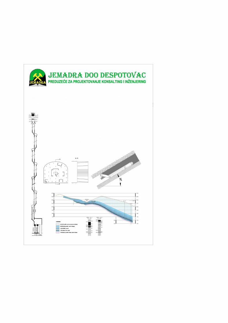
UPUTSTVO AUTORIMA Časopis RUDARSKI RADOVI izlazi četiri puta godišnje i objavljuje naučne, stručne i pregledne radove. Za
objavljivanje u časopisu prihvataju se isključivo originalni radovi koji nisu prethodno objavljivani i nisu istovremeno podneti za objavljivanje negde drugde. Radovi se dostavljaju i na srpskom i na engleskom jeziku. Radovi se anonimno recenziraju od strane recenzenta posle čega uredništvo donosi odluku o objavljivanju. Rad priložen za objavljivanje treba da bude pripremljen prema dole navedenom uputstvu da bi bio uključen u proceduru recenziranja. Neodgovarajuće pripremljeni rukopisi biće vraćeni autoru na doradu.
Obim i font. Rad treba da je napisan na papiru A4 formata (210x297 mm), margine (leva, desna, gornja i donja) sa po 25 mm, u Microsoft Wordu novije verzije, fontom Times New Roman, veličine 12, sa razmakom 1,5 reda, obostrano poravnat prema levoj i desnoj margini. Preporučuje se da celokupni rukopis ne bude manji od 5 strana i ne veći od 10 strana.
Naslov rada treba da je ispisan velikim slovima, bold. Ispod naslova rada pišu se imena autora i institucija u kojoj rade. Autor rada zadužen za korespodenciju sa uredništvom mora da navede svoju e-mail adresu za kontakt u fusnoti.
Izvod se nalazi na početku rada i treba biti dužine do 200 reči, da sadrži cilj rada, primenjene metode, glavne rezultate i zaključke. Veličina fonta je 10, italic.
Ključne reči se navode ispod izvoda. Treba da ih bude minimalno 3, a maksimalno 6. Veličina fonta je 10, italic.
Osnovni tekst. Radove treba pisati jezgrovito, razumljivim stilom i logičkim redom koji, po pravilu, uključuje uvodni deo s određenjem cilja ili problema rada, opis metodologije, prikaz dobijenih rezultata, kao i diskusiju rezultata sa zaključcima i implikacijama.
Glavni naslovi trebaju biti urađeni sa veličinom fonta 12, bold, sve velika slova i poravnati sa levom marginom. Podnaslovi se pišu sa veličinom fonta 12, bold, poravnato prema levoj margini, velikim i malim slovima. Slike i tabele. Svaka ilustracija i tabela moraju biti razumljive i bez čitanja teksta, odnosno, moraju imati redni
broj, naslov i legendu (objašnjenje oznaka, šifara, skraćenica i sl.). Tekst se navodi ispod slike, a iznad tabele. Redni brojevi slika i tabela se daju arapskim brojevima.
Reference u tekstu se navode u ugličastim zagradama, na pr. [1,3]. Reference se prilažu na kraju rada na sledeći način:
[1] B.A. Willis, Mineral Procesing Technology, Oxford, Perganom Press, 1979, str. 35. (za poglavlje u knjizi) [2] H. Ernst, Research Policy, 30 (2001) 143–157. (za članak u časopisu) [3] www: http://www.vanguard.edu/psychology/apa.pdf (za web dokument) Navođenje neobjavljenih radova nije poželjno, a ukoliko je neophodno treba navesti što potpunije podatke o
izvoru. Zahvalnost se daje po potrebi, na kraju rada, a treba da sadrži ime institucije koja je finansirala rezultate koji se
daju u radu, sa nazivom i brojem projekta; ili ukoliko rad potiče iz magistarske teze ili doktorske disertacije, treba dati naziv teze/disertacije, mesto, godinu i fakultet na kojem je odbranjena. Veličina fonta 10, italic.
Radovi se šalju prevashodno elektronskom poštom ili u drugom elektronskom obliku. Adresa uredništva je: Časopis RUDARSKI RADOVI
Institut za rudarstvo i metalurgiju Zeleni bulevar 35, 19210 Bor E-mail: [email protected] ; [email protected] Telefon: 030/435-164; 030/454-110
Svim autorima se zahvaljujemo na saradnji.
INSTRUCTIONS FOR THE AUTHORS
MINING ENGINEERING Journal is published four times per a year and publishes the scientific, technical
and review paper works. Only original works, not previously published and not simultaneously submitted for publication elsewhere, are accepted for publication in the journal. The papers should be submitted in both, Serbian and English language. The papers are anonymously reviewed by the reviewers after that the editors decided to publish. The submitted work for publication should be prepared according to the instructions below as to be included in the procedure of reviewing. Inadequate prepared manuscripts will be returned to the author for finishing.
Volume and Font size. The work needs to be written on A4 paper (210x297 mm), margins (left, right, upper and bottom) with each 25 mm, in the Microsoft Word later version, font Times New Roman, size 12, with 1.5 line spacing, justified to the left and right margins. It is recommended that the entire manuscript cannot be less than 5 pages and not exceed 10 pages.
Title of Work should be written in capital letters, bold, in Serbian and English. Under the title, the names of authors and institutions where they work are written under the title. The author of work, responsible for correspondence with the editorial staff, must provide his/her e-mail address for contact in a footnote.
Abstract is at the beginning of work and should be up to 200 words, include the aim of the work, the applied methods, the main results and conclusions. The font size is 10, italic.
Key words are listed below abstract. They should be minimum 3 and maximum of 6. The font size is 10, italic. Basic text. The papers should be written concisely, in understandable style and logical order that, as a rule,
including the introductory section with a definition of the aim or problem, a description of the methodology, presentation of the results as well as a discussion of the results with conclusions and implications.
Main titles should be done with the font size 12, bold, all capital letters and aligned with the left margin. Subtitles are written with the font size 12, bold, aligned to the left margin, large and small letters. Figure and Tables. Each figure and table must be understandable without reading the text, i.e., must have a
serial number, title and legend (explanation of marks, codes, abbreviations, etc.). The text is stated below the figure and above the table. Serial numbers of figures and tables are given in Arabic numbers.
References in the text are referred to in angle brackets, exp. [1, 3]. References are enclosed at the end in the following way:
[1] Willis B. A., Mineral Procesing Technology, Oxford, Pergamon Press, 1979, pg. 35. (for the chapter in a book) [2] Ernst H., Research Policy, 30 (2001) 143–157. (for the article in a journal) [3] www: http://www.vanguard.edu/psychology/apa.pdf (for web document)
Specifying the unpublished works is not desirable and, if it is necessary, as much as possible data on the source should be listed.
Acknowledgement is given where appropriate, at the end of the work and should include the name of institution that funded the given results in the work, with the name and number of project, or if the work is derived from the master theses or doctoral dissertation, it should give the name of thesis / dissertation, place, year and faculty where it was defended. Font size is 10, italic.
The paper works are primarily sent by e-mail or in other electronic form. Editorial address : Journal MINING ENGINEERING
Mining and Metallurgy Institute 35 Zeleni bulevar, 19210 Bor E-mail: [email protected]; [email protected] Telephone: +381 (0) 30/435-164; +381 (0) 30/454-110 We are thankful for all authors on cooperation