Embed Size (px)
Citation preview
Set A
Set B
003-360 Rev 2
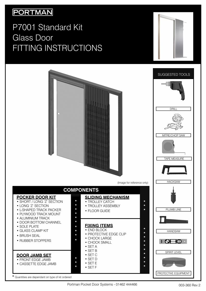
P7001 Standard Kit
Glass Door
FITTING INSTRUCTIONS
SUGGESTED TOOLS
COMPONENTS
PROTECTIVE EQUIPMENT
POCKER DOOR KIT• SHORT / LONG ‘Z’ SECTION
• LONG ’Z’ SECTION
• L-SHAPED TRACK PACKER
• PLYWOOD TRACK MOUNT
• ALUMINIUM TRACK
• DOOR BOTTOM CHANNEL
• SOLE PLATE
• GLASS CLAMP KIT
• BRUSH SEAL
• RUBBER STOPPERS
DOOR JAMB SET• FRONT EDGE JAMB
• CASSETTE EDGE JAMB
SLIDING MECHANISM• TROLLEY CATCH
• TROLLEY ASSEMBLY
• FLOOR GUIDE
FIXING ITEMS• END BLOCK
• PROTECTIVE EDGE CLIP
• CHOCK LARGE
• CHOCK SMALL
• SET A
• SET B
• SET C
• SET D
• SET E
• SET F
*
*
*
*
*
*
*
*
*
*
*
*
*
*
*
*
*
*
*
*
*
*
*
*
*
*
SPIRIT LEVEL
HANDSAW
PLUMB LINE
HACKSAW
TAPE MEASURE
MITRE/CHOP SAW
DRILL
(Image for reference only)
* Quantities are dependant on type of kit ordered
Portman Pocket Door Systems - 01462 444466
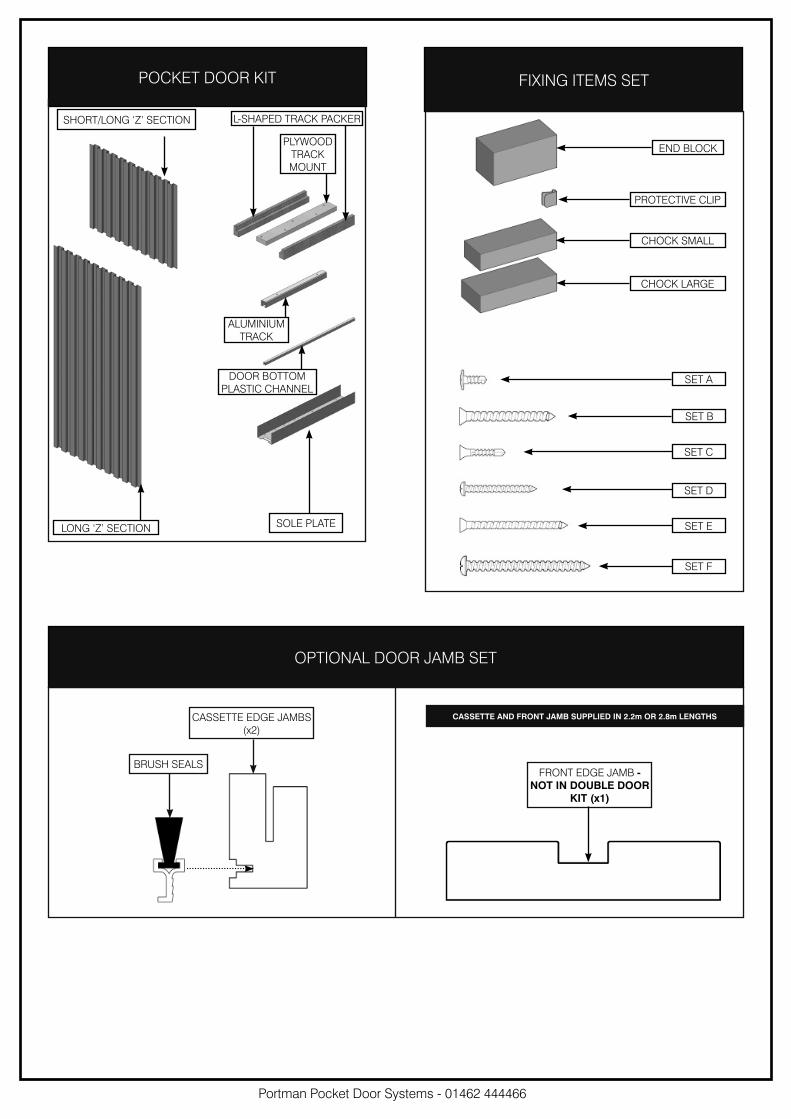
POCKET DOOR KIT
OPTIONAL DOOR JAMB SET
FIXING ITEMS SET
SHORT/LONG ‘Z’ SECTION
SOLE PLATELONG ‘Z’ SECTION
L-SHAPED TRACK PACKER
PLYWOOD
TRACK
MOUNT
ALUMINIUM
TRACK
DOOR BOTTOM
PLASTIC CHANNEL
SET E
SET D
SET C
SET B
SET A
END BLOCK
PROTECTIVE CLIP
CHOCK SMALL
CHOCK LARGE
Portman Pocket Door Systems - 01462 444466
CASSETTE EDGE JAMBS
(x2)
BRUSH SEALSFRONT EDGE JAMB -
NOT IN DOUBLE DOOR
KIT (x1)
CASSETTE AND FRONT JAMB SUPPLIED IN 2.2m OR 2.8m LENGTHS
SET F
Portman Pocket Door Systems - 01462 444466
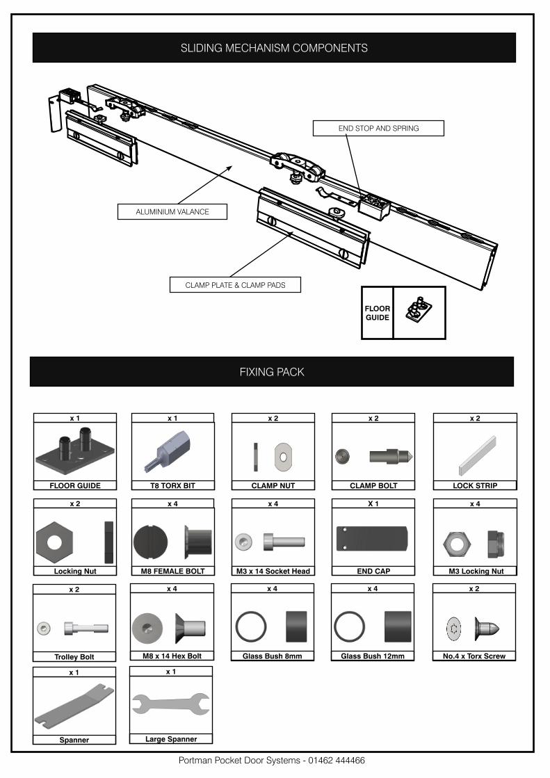
SLIDING MECHANISM COMPONENTS
FLOOR
GUIDE
FIXING PACK
x 2 x 4 x 4 X 1 x 4
x 4 x 4 x 4 x 2x 2
x 1
M3 x 14 Socket Head END CAP
M8 x 14 Hex Bolt Glass Bush 8mm Glass Bush 12mm No.4 x Torx Screw
M8 FEMALE BOLT M3 Locking NutLocking Nut
Trolley Bolt
Spanner
x 1
Large Spanner
x 1 x 1 x 2 x 2 x 2
CLAMP NUT CLAMP BOLTT8 TORX BIT LOCK STRIP FLOOR GUIDE
CLAMP PLATE & CLAMP PADS
ALUMINIUM VALANCE
END STOP AND SPRING
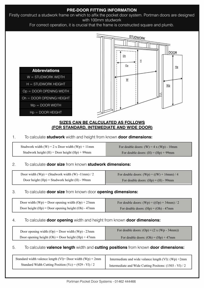
PRE-DOOR FITTING INFORMATION
Firstly construct a studwork frame on which to affix the pocket door system. Portman doors are designed
with 100mm studwork
For correct operation, it is crucial that the frame is constructed square and plumb.
Abbreviations
W = STUDWORK WIDTH
H = STUDWORK HEIGHT
Op = DOOR OPENING WIDTH
Oh = DOOR OPENING HEIGHT
Wp = DOOR WIDTH
Hp = DOOR HEIGHT
SIZES CAN BE CALCULATED AS FOLLOWS
(FOR STANDARD, INTEMEDIATE AND WIDE DOOR)
1. To calculate studwork width and height from known door dimensions:
2. To calculate door size from known studwork dimensions:
4. To calculate door opening width and height from known door dimensions:
3. To calculate door size from known door opening dimensions:
Portman Pocket Door Systems - 01462 444466
Studwork width (W) = 2 x Door width (Wp) + 11mm
Studwork height (H) = Door height (Hp) + 99mm
For double doors: (W) = 4 x (Wp) - 10mm
For double doors: (H) = (Hp) + 99mm
Door width (Wp) = (Studwork width (W) -11mm) / 2
Door height (Hp) = Studwork height (H) - 99mm
For double doors: (Wp) = ((W) + 16mm) / 4
For double doors: (Hp) = (H) - 99mm
Door width (Wp) = Door opening width (Op) + 23mm
Door height (Hp) = Door opening height (Oh) - 47mm
For double doors: (Wp) = ((Op) + 34mm) / 2
For double doors: (Hp) = (Oh) - 47mm
Door opening width (Op) = Door width (Wp) - 23mm
Door opening height (Oh) = Door height (Hp) + 47mm
For double doors: (Op) = (2 x (Wp - 34mm))
For double doors: (Oh) = (Hp) + 47mm
5. To calculate valence length width and cutting positions from known door dimensions:
Standard width valence length (Vl)= Door width (Wp) + 2mm
Standard Width Cutting Position (Vc) = (929 - Vl) / 2
Intermediate and wide valance length (Vl): (Wp) +2mm
Intermediate and Wide Cutting Positons: (1503 - Vl) / 2
Portman Pocket Door Systems - 01462 444466
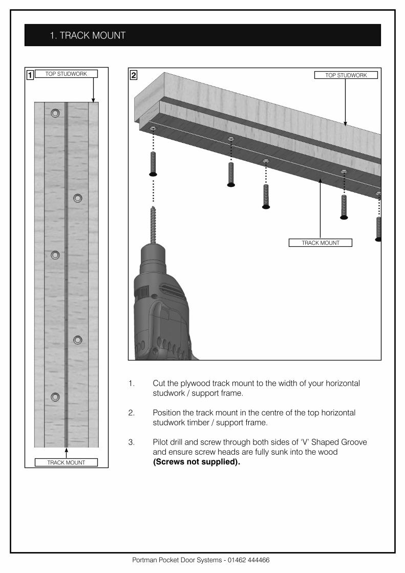
1. TRACK MOUNT
1. Cut the plywood track mount to the width of your horizontal
studwork / support frame.
2. Position the track mount in the centre of the top horizontal
studwork timber / support frame.
3. Pilot drill and screw through both sides of ‘V’ Shaped Groove
and ensure screw heads are fully sunk into the wood
(Screws not supplied).
TOP STUDWORK
TRACK MOUNT
TOP STUDWORK
TRACK MOUNT
1 2
Portman Pocket Door Systems - 01462 444466
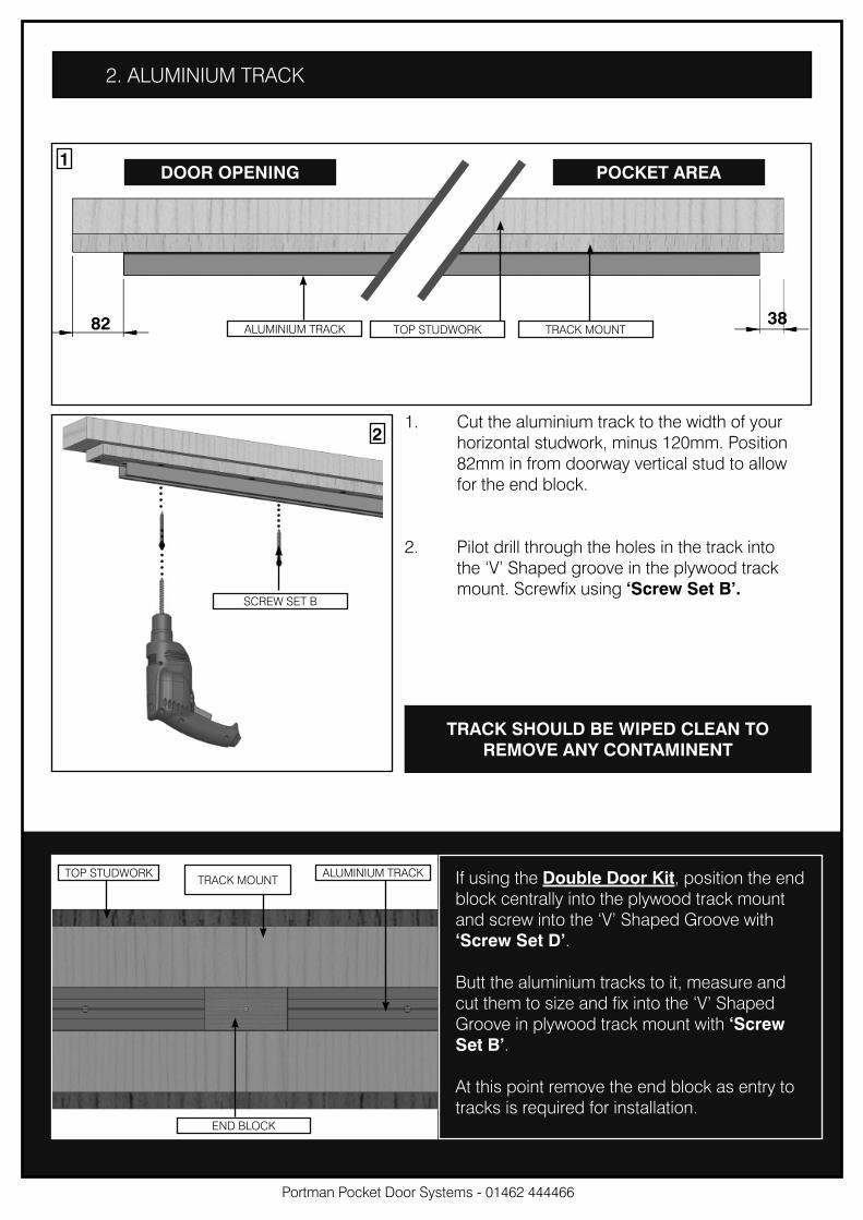
2. ALUMINIUM TRACK
82
1
21. Cut the aluminium track to the width of your
horizontal studwork, minus 120mm. Position
82mm in from doorway vertical stud to allow
for the end block.
2. Pilot drill through the holes in the track into
the ‘V’ Shaped groove in the plywood track
mount. Screwfix using ‘Screw Set B’.A
TOP STUDWORK TRACK MOUNTALUMINIUM TRACK
SCREW SET B
DOOR OPENING
38
TRACK SHOULD BE WIPED CLEAN TO
REMOVE ANY CONTAMINENT
If using the Double Door Kit, position the end
block centrally into the plywood track mount
and screw into the ‘V’ Shaped Groove with
‘Screw Set D’.
Butt the aluminium tracks to it, measure and
cut them to size and fix into the ‘V’ Shaped
Groove in plywood track mount with ‘Screw
Set B’.
At this point remove the end block as entry to
tracks is required for installation.
TOP STUDWORK ALUMINIUM TRACK
END BLOCK
TRACK MOUNT
POCKET AREA
Portman Pocket Door Systems - 01462 444466
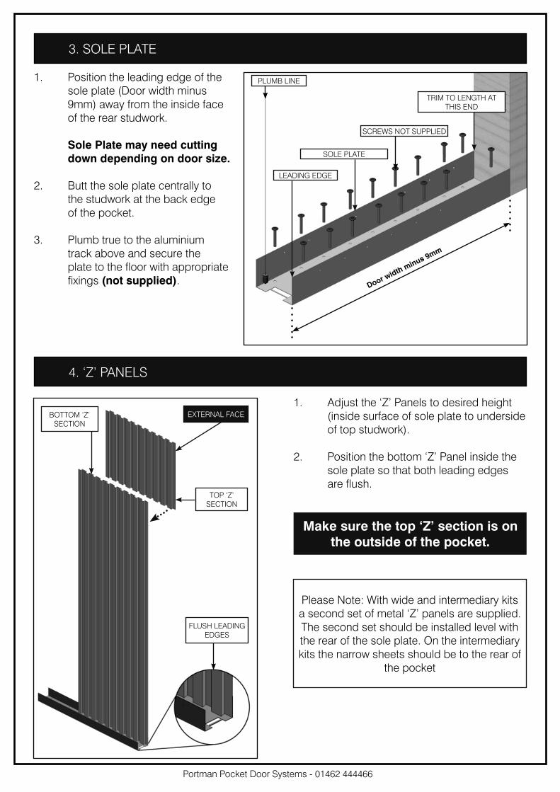
3. SOLE PLATE
1. Position the leading edge of the
sole plate (Door width minus
9mm) away from the inside face
of the rear studwork.
Sole Plate may need cutting
down depending on door size.
2. Butt the sole plate centrally to
the studwork at the back edge
of the pocket.
3. Plumb true to the aluminium
track above and secure the
plate to the floor with appropriate
fixings (not supplied).
PLUMB LINE
SOLE PLATE
TRIM TO LENGTH AT
THIS END
LEADING EDGE
SCREWS NOT SUPPLIED
4. ‘Z’ PANELS
1. Adjust the ‘Z’ Panels to desired height
(inside surface of sole plate to underside
of top studwork).
2. Position the bottom ‘Z’ Panel inside the
sole plate so that both leading edges
are flush.
Make sure the top ‘Z’ section is on
the outside of the pocket.
Please Note: With wide and intermediary kits
a second set of metal ‘Z’ panels are supplied.
The second set should be installed level with
the rear of the sole plate. On the intermediary
kits the narrow sheets should be to the rear of
the pocket
TOP ‘Z’
SECTION
BOTTOM ‘Z’
SECTION
FLUSH LEADING
EDGES
EXTERNAL FACE
Door width m
inus 9mm
Portman Pocket Door Systems - 01462 444466
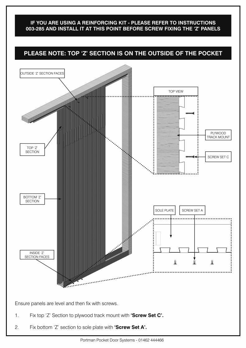
Ensure panels are level and then fix with screws.
1. Fix top ‘Z’ Section to plywood track mount with ‘Screw Set C’.
2. Fix bottom ‘Z’ section to sole plate with ‘Screw Set A’.
TOP ‘Z’
SECTION
BOTTOM ‘Z’
SECTION
OUTSIDE ‘Z’ SECTION FACES
INSIDE ‘Z’
SECTION FACES
TOP VIEW
PLYWOOD
TRACK MOUNT
SOLE PLATE
SCREW SET C
SCREW SET A
PLEASE NOTE: TOP ‘Z’ SECTION IS ON THE OUTSIDE OF THE POCKET
IF YOU ARE USING A REINFORCING KIT - PLEASE REFER TO INSTRUCTIONS
003-285 AND INSTALL IT AT THIS POINT BEFORE SCREW FIXING THE ‘Z’ PANELS

Portman Pocket Door Systems - 01462 444466
5. PANEL JOINING
At the back of the pocket, place the protective edge clip onto the ‘Z’ section, covering where the
panels join.
In the last ‘Z’ section slot towards the back of the inside pocket, push the large chock into the top
‘Z’ section and the two small chocks into the bottom ‘Z’ section.
This pushes the edge outwards so the door does not snag on it when closing.
For intermediary and wide kits, fit the chocks in the first and last slot in the rear ‘Z’ sections as
detailed above. Fit protective edge clips to all joints on rear panels.
Repeat stages 4 - 5 on the other side of the pocket.
LARGE CHOCK
SMALL CHOCK
PROTECTIVE EDGE CLIP
1. Screw through from
outside to join panels
together in five
locations using ‘Screw
Set A’ (pilot holes not
required).
1
INSIDE CASSETTE VIEW
OUTSIDE CASSETTE VIEW
ENSURE WHEN
SCREWING THE TWO
SHEETS THEY ARE
STRAIGHT AND DO NOT
BECOME BOWED AS
THE SCREW PUSHES
THROUGH
PLASTIC CLAMP STRIP
GLASS SPACER
ASSEMBLE GLASS CLAMPS ON DOOR
PLASTIC CLAMP STRIP
GLASS SPACER
ASSEMBLE GLASS CLAMPS ON DOOR
Portman Pocket Door Systems - 01462 444466
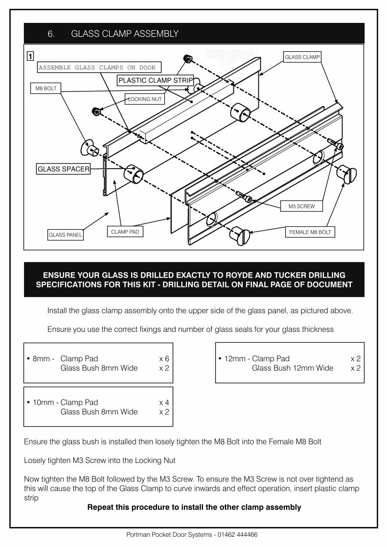
6. GLASS CLAMP ASSEMBLY
1
Install the glass clamp assembly onto the upper side of the glass panel, as pictured above.
Ensure you use the correct fixings and number of glass seals for your glass thickness
Ensure the glass bush is installed then losely tighten the M8 Bolt into the Female M8 Bolt
Losely tighten M3 Screw into the Locking Nut
Now tighten the M8 Bolt followed by the M3 Screw. To ensure the M3 Screw is not over tightend as
this will cause the top of the Glass Clamp to curve inwards and effect operation, insert plastic clamp
strip
Repeat this procedure to install the other clamp assembly
ENSURE YOUR GLASS IS DRILLED EXACTLY TO ROYDE AND TUCKER DRILLING
SPECIFICATIONS FOR THIS KIT - DRILLING DETAIL ON FINAL PAGE OF DOCUMENT
GLASS CLAMP
GLASS PANEL
M3 SCREW
M8 BOLT
LOCKING NUT
CLAMP PAD FEMALE M8 BOLT
• 8mm - Clamp Pad x 6
Glass Bush 8mm Wide x 2
• 10mm - Clamp Pad x 4
Glass Bush 8mm Wide x 2
• 12mm - Clamp Pad x 2
Glass Bush 12mm Wide x 2

12mm GLASS 12mm GLASS 10mm GLASS 10mm GLASS 8mm GLASS 8mm GLASS
1. Set the door guide to your glass width as
shown in illustrations below .
2. Place the door guide inside the sole plate on
the edge of the outer cut out and pencil mark
all 3 hole positions.
3. Pilot drill the holes in preperation for screwing.
4. Fix the door guide in place using
suitable countersunk screws (not provided)
to complete the installation.
7. DOOR GUIDE
Portman Pocket Door Systems - 01462 444466
8mm Glass 12mm Glass10mm Glass
1
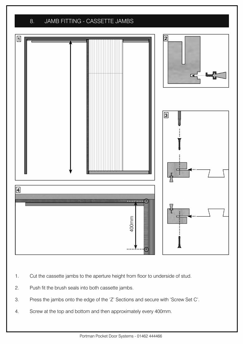
8. JAMB FITTING - CASSETTE JAMBS
2
1. Cut the cassette jambs to the aperture height from floor to underside of stud.
2. Push fit the brush seals into both cassette jambs.
3. Press the jambs onto the edge of the ‘Z’ Sections and secure with ‘Screw Set C’.
4. Screw at the top and bottom and then approximately every 400mm.
40
0m
m
4
Portman Pocket Door Systems - 01462 444466
3
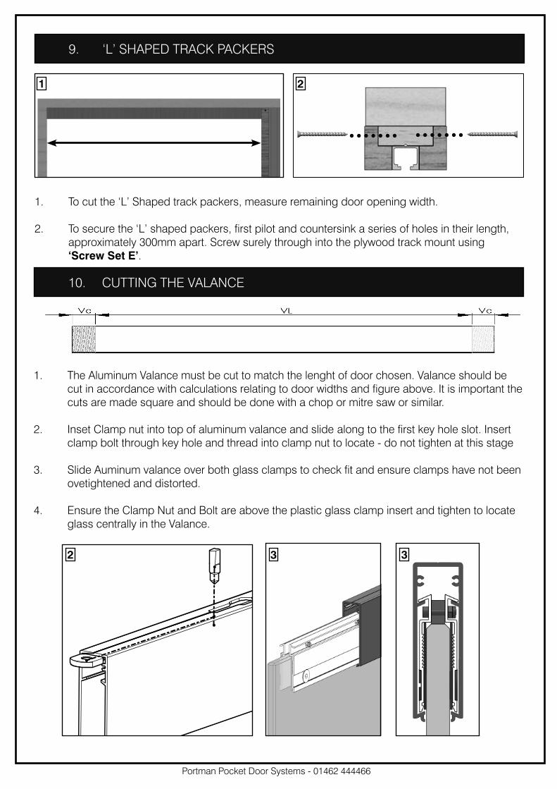
1. To cut the ‘L’ Shaped track packers, measure remaining door opening width.
2. To secure the ‘L’ shaped packers, first pilot and countersink a series of holes in their length,
approximately 300mm apart. Screw surely through into the plywood track mount using
‘Screw Set E’.
9. ‘L’ SHAPED TRACK PACKERS
1 2
Portman Pocket Door Systems - 01462 444466
10. CUTTING THE VALANCE
33
1. The Aluminum Valance must be cut to match the lenght of door chosen. Valance should be
cut in accordance with calculations relating to door widths and figure above. It is important the
cuts are made square and should be done with a chop or mitre saw or similar.
2. Inset Clamp nut into top of aluminum valance and slide along to the first key hole slot. Insert
clamp bolt through key hole and thread into clamp nut to locate - do not tighten at this stage
3. Slide Auminum valance over both glass clamps to check fit and ensure clamps have not been
ovetightened and distorted.
4. Ensure the Clamp Nut and Bolt are above the plastic glass clamp insert and tighten to locate
glass centrally in the Valance.
2

12. TROLLEY CATCHES
21PLYWOOD TRACK MOUNT
ALUMINIUM TRACK
3
SPRING
SPRING
FIXING
BOLT
SPRING
TENSION
SCREW
1. Place trolley catches in front and back of aluminium track.
2. Fix trolley catches in required positions within the aluminium track by removing the spring
giving access to the centre hole locking grub screw. A 3mm allen key is required.
3. Replace the spring and adjust the clamping bolt to the desired tension to hold the trollies in
place using an M5 allen key.
Portman Pocket Door Systems - 01462 444466
11. TROLLEY INSTALLATION
1. Assemble the trolley as pictured, screwing the bolt up into the trolley.
2. Slide both trolleys into the top rail at the front and back.
1 2
Portman Pocket Door Systems - 01462 444466
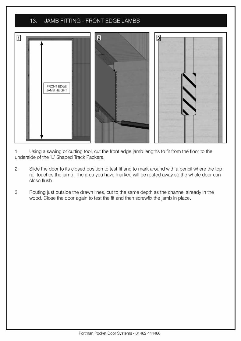
13. JAMB FITTING - FRONT EDGE JAMBS
1. Using a sawing or cutting tool, cut the front edge jamb lengths to fit from the floor to the
underside of the ‘L’ Shaped Track Packers.
2. Slide the door to its closed position to test fit and to mark around with a pencil where the top
rail touches the jamb. The area you have marked will be routed away so the whole door can
close flush
3. Routing just outside the drawn lines, cut to the same depth as the channel already in the
wood. Close the door again to test the fit and then screwfix the jamb in place.
1 2
FRONT EDGE
JAMB HEIGHT
3
Portman Pocket Door Systems - 01462 444466
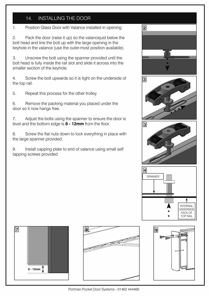
14. INSTALLING THE DOOR
1. Position Glass Door with Valance installed in opening
2. Pack the door (raise it up) so the valancejust below the
bolt head and line the bolt up with the large opening in the
keyhole in the valance (use the outer-most position available).
3. Unscrew the bolt using the spanner provided until the
bolt head is fully inside the rail slot and slide it across into the
smaller section of the keyhole.
4. Screw the bolt upwards so it is tight on the underside of
the top rail.
5. Repeat this process for the other trolley.
6. Remove the packing material you placed under the
door so it now hangs free.
7. Adjust the bolts using the spanner to ensure the door is
level and the bottom edge is 8 - 12mm from the floor.
8. Screw the flat nuts down to lock everything in place with
the large spanner provided.
9. Install capping plate to end of valance using small self
tapping screws provided
8 - 12mm
87 9
2
3
3
4
SPANNER
INTERNAL
UNDERSIDE
FACE OF
TOP RAIL
Portman Pocket Door Systems - 01462 444466
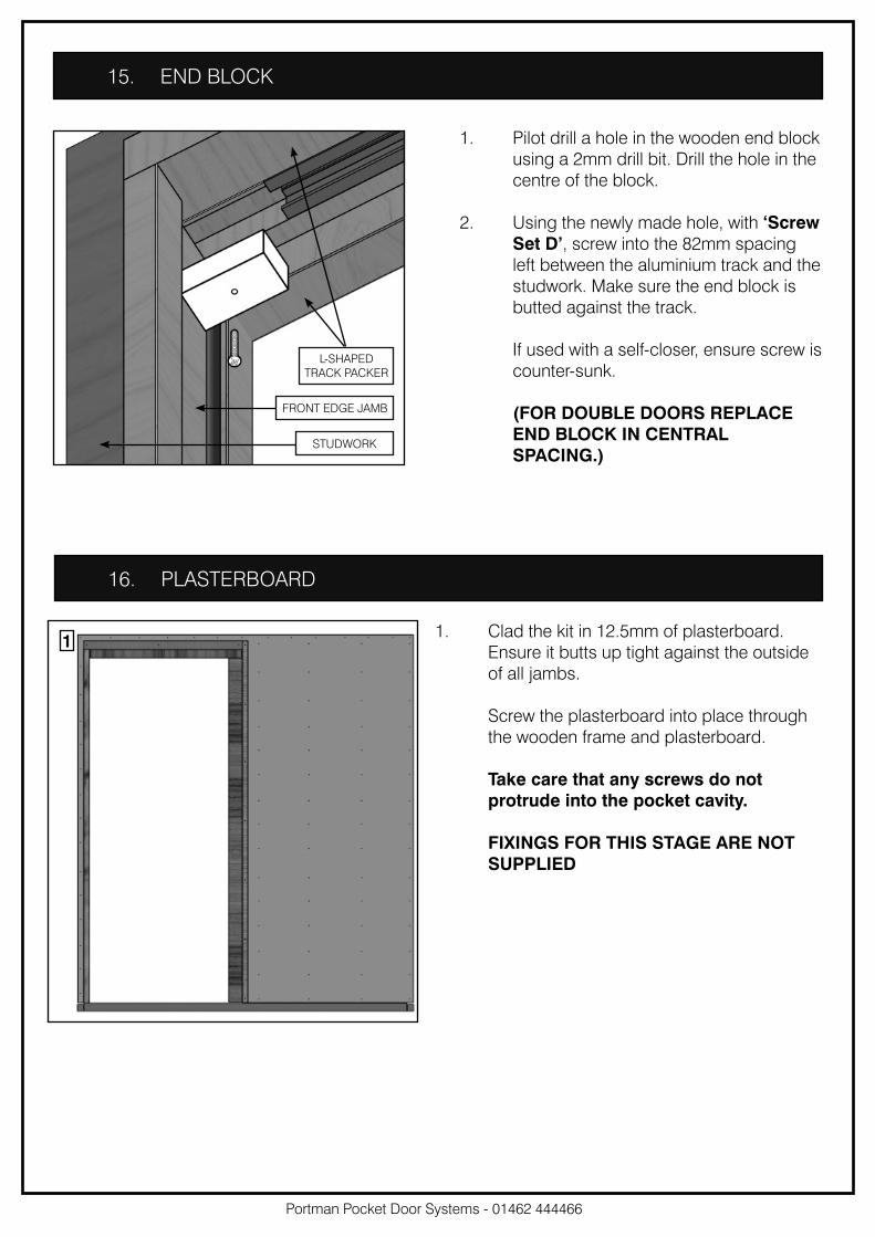
15. END BLOCK
1. Pilot drill a hole in the wooden end block
using a 2mm drill bit. Drill the hole in the
centre of the block.
2. Using the newly made hole, with ‘Screw
Set D’, screw into the 82mm spacing
left between the aluminium track and the
studwork. Make sure the end block is
butted against the track.
If used with a self-closer, ensure screw is
counter-sunk.
(FOR DOUBLE DOORS REPLACE
END BLOCK IN CENTRAL
SPACING.)
16. PLASTERBOARD
1. Clad the kit in 12.5mm of plasterboard.
Ensure it butts up tight against the outside
of all jambs.
Screw the plasterboard into place through
the wooden frame and plasterboard.
Take care that any screws do not
protrude into the pocket cavity.
FIXINGS FOR THIS STAGE ARE NOT
SUPPLIED
1
L-SHAPED
TRACK PACKER
FRONT EDGE JAMB
STUDWORK
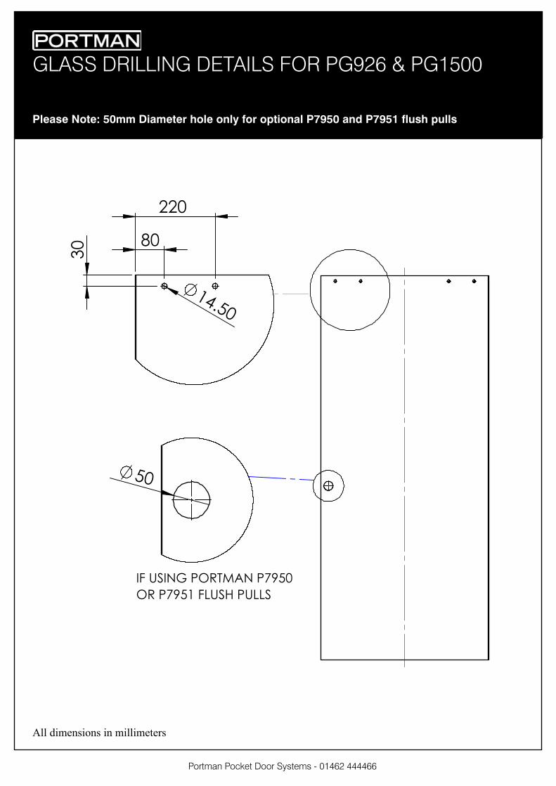
GLASS DRILLING DETAILS FOR PG926 & PG1500
Portman Pocket Door Systems - 01462 444466
Please Note: 50mm Diameter hole only for optional P7950 and P7951 flush pulls
!"#$%
&%
''%
(%
$%
)* +,)-. /01234- /56$%
01 /56$! *7+,8 /+77,
All dimensions in millimeters