Embed Size (px)
Citation preview

1
AUTODESK INVENTORانجمن اینونتور ایران/ هندبوک مهندسی نرم افزار
Autodesk Inventor Engineer s Handbook
انجمن اینونتور ایران
www.irinventor.com
Tel: 09352191813 &
021-46088862
قابل توجه خوانندگان عزیر: کلیه مطالب [
Autodeskاین هندبوک از سایت شرکت
]کپی برداری شده است.
Autodesk Inventor هندبوک مهندسی نرم افزار
Gears Calculation
Spur Gear
Generator

2
AUTODESK INVENTORانجمن اینونتور ایران/ هندبوک مهندسی نرم افزار
Basic geometric calculation
Input Parameters
Gear type - internal or external gear
Gear ratio and tooth numbers
Pressure angle (the angle of tool profile) α
Helix angle β
Module m (for metric calculation)
Diametral Pitch P (for English units)
NoteModule and Diametral Pitch are reciprocal values.
Unit addendum a *
Unit clearance c *
Unit dedendum fillet r f *
Gear widths b 1 , b 2
Unit corrections x 1 , x 2
NoteFor internal gears the opposite sign for unit correction is used in following formulas.
Summary of unit correction Σ x = x 1 + x 2
Auxiliary Geometric Calculations
Distribution of Unit Corrections for Single Gears
Design of the Module and Tooth Number
Design of Tooth Number
Design According to the Strength Calculation
Calculation of Helix Angle
Calculation of Summary Correction
Design of Gearing Width
3
AUTODESK INVENTORانجمن اینونتور ایران/ هندبوک مهندسی نرم افزار
Calculation of Maximum Dedendum Filleting
Calculated parameters
Gearing number
for i > 1
u = i
for i < 1
u = 1 / i
Tangential module
Normal pitch
p = π m

4
AUTODESK INVENTORانجمن اینونتور ایران/ هندبوک مهندسی نرم افزار
Axial pitch
p t = π m t
Base pitch
p tB = p t cos α t
Helix angle on the basic cylinder
sin β b = sin β cos α
Axial pressure angle
Rolling/working pressure angle
Axial rolling/working pressure angle
Pitch diameter
d 1,2 = z 1,2 m t
Base circle diameter
d b1,2 = d 1,2 cos α t
Theoretical center distance

5
AUTODESK INVENTORانجمن اینونتور ایران/ هندبوک مهندسی نرم افزار
Real center distance
Feed factor/addendum lowering
Outside diameter
d a1,2 = d 1,2 + 2m (a * + x 1,2 - ∆ y )
- for internal gearing the interference
check is done as well
for km > 0 is accomplished by addendum lowering d a2 =
d a2 - 2km
Root diameter
d f1,2 = d 1,2 - 2m (a * + c * - x 1,2 )
Work pitch diameter
Virtual Number of Teeth

6
AUTODESK INVENTORانجمن اینونتور ایران/ هندبوک مهندسی نرم افزار
Virtual Pitch Diameter
d n1,2 = z v1,2 m
Virtual Base Circle Diameter
d bn1,2 = d n1,2 cos(α)
Virtual Outside Diameter
d an1,2 = d n1,2 + d a1,2 – d1,2
Tooth thickness (measured normally on the pitch diameter)
s 1,2 = p/2 + 2m x1,2 tg α
Tooth width on the chord (measured normally)
s c1,2 = s 1,2 cos 2 α
Addendum height above the chord
Unit addendum width (measured normally)
where:
Operating width of gearings

7
AUTODESK INVENTORانجمن اینونتور ایران/ هندبوک مهندسی نرم افزار
b w = min( b 1 , b 2 )
Relative width
Factor of mesh duration
ε γ = ε α + ε β
Factor of profile mesh duration
(the minus sign applies to internal gearing)
Factor of step mesh duration
Minimum correction without tapering
where:
a 0 * = a * + c * - r f
* (1 - sin α)
Minimum correction without undercut
Minimum correction with the allowable undercut

8
AUTODESK INVENTORانجمن اینونتور ایران/ هندبوک مهندسی نرم افزار
Checking chordal dimension
W 1,2 = ((z w - 0.5) π + z 1,2 inv α t ) m cos α) + 2 x 1,2 m sin α
where: z w is the tooth number across which the measure is performed
Checking size across rollers/balls
- for even tooth number
M 1,2 = D s1,2 + d M
- for odd tooth number
M 1,2 = D s1,2 cos(90 / z 1,2 ) + d M
where:
d M wire (ball) diameter
diameter of the wire center circle
wire (ball) contact angle

9
AUTODESK INVENTORانجمن اینونتور ایران/ هندبوک مهندسی نرم افزار
Design of the module and tooth number
Module for external gear
Module for internal gear
Tooth numbers
The minus sign (-) applies to the internal gear.
Design of Tooth number:
The minus sign (-) applies to internal gearing.
.
Helix Angle Calculation:
Other parameters are calculated as in the Basic geometric calculation
Axial pressure angle

10
AUTODESK INVENTORانجمن اینونتور ایران/ هندبوک مهندسی نرم افزار
Axial rolling/working pressure angle
Unit summary correction
Unit dedendum filleting

11
AUTODESK INVENTORانجمن اینونتور ایران/ هندبوک مهندسی نرم افزار
Backlash of gears
Backlash types (defined for each gear in a gear set)
Real gears must be manufactured with a specific backlash allowance. Designate the allowance by
considering the machining and working conditions.
In spur and helical gearing, there are two alternate ways to obtain the appropriate amount of
backlash. First, decrease tooth thickness by sinking the hob deeper into the blank than the
theoretical standard depth is. Second, increase the center distance than theoretically computed.
When designing a backlash, consider following factors:
Lubricant space required. Differential expansion between the gear components and the housing. Errors in machining. Run-out of both gears, errors in profile, pitch, tooth thickness, helix angle
and center distance. The smaller the amount of backlash, the more accurate the machining of the gears is.
Working conditions such as frequent reversing or overrunning load.
The amount of backlash must not be excessive for the requirements of the job. Ensure it is
sufficient so that machining costs are not higher than necessary.
It is customary to make half of the allowance for backlash on the tooth thickness of each gear of
a pair, although there are exceptions. For example, on pinions having low numbers of teeth, it
provides all the allowance on the driven gear. It avoids weakening the pinion teeth.
Circular backlash j t [mm/in] Normal backlash j n [mm/in] Center backlash j r [mm/in] Angular backlash j Θ [deg]
Type of Gear
Meshes
The Relation between
Circular Direction j t and
Normal Direction j n
The Relation between Circular
Direction j t and Center Direction
j r
The Relation between
Circular Direction j t and
Angular Backlash j Θ
Spur Gear j n = j t cos α

12
AUTODESK INVENTORانجمن اینونتور ایران/ هندبوک مهندسی نرم افزار
Helical Gear j nn = j tt cos α n cos β
Backlash of Helical Gear Mesh
The helical gear has two kinds of backlash when referring to the tooth space. There is a cross
section in the normal direction of the tooth surface “n”, and a cross section in the transverse
direction perpendicular to the axis “t”.

13
AUTODESK INVENTORانجمن اینونتور ایران/ هندبوک مهندسی نرم افزار
j nn Backlash in the direction normal to the tooth surface
j nt Backlash in the circular direction in the cross section normal to the
tooth
j tn Backlash in the direction normal to the tooth surface in the cross section
perpendicular to the axis
j tt Backlash in the circular direction perpendicular to the axis
In the plane normal to
the tooth: j nn = j nt cos α n
On the pitch surface: j nt = j tt cos β
In the plane perpendicular to the axis
j tn = j tt cos α t
where:
α Pressure angle
α n Pressure angle in normal direction, α = α n

14
AUTODESK INVENTORانجمن اینونتور ایران/ هندبوک مهندسی نرم افزار
α t Pressure angle in transverse direction
β Helix angle
d Pitch diameter

15
AUTODESK INVENTORانجمن اینونتور ایران/ هندبوک مهندسی نرم افزار
Calculation of strength proportions
Input values:
Input power P 1
Input speed n 1
Gearing ratio i
Gearing efficiency η
Calculated values
Output: P 2 = P 1 η
Output speed:
Metric units
Input moment:
Tangential/circumferential force:
Circumferential speed:
Resonance speed:
ANSI (English) units
Input moment:
Tangential/circumferential force:
Circumferential speed:
Resonance speed:
Output moment
M k2 = M k1 i η
Radial force
F r = F t tg α tw
Axial force
F a = F t tg β

16
AUTODESK INVENTORانجمن اینونتور ایران/ هندبوک مهندسی نرم افزار
Normal force

17
AUTODESK INVENTORانجمن اینونتور ایران/ هندبوک مهندسی نرم افزار
Strength calculation according to Bach
Based on the fixed-end beam calculation, and anticipates that the total circumferential force can
only be carried by one tooth.
Allowable load
F all = π c b m ≥ F t
where:
c = 0.065 σ Ab tooth allowable stress in bending [MPa, psi]
σ Ab allowable stress in bending (material property)
b tooth gearing width
m module
F t circumferential force acting on the gearing
Safety factor
S = F all / F t

18
AUTODESK INVENTORانجمن اینونتور ایران/ هندبوک مهندسی نرم افزار
Strength calculation with Merrit method
Based on the fixed-end beam calculation. Anticipates that the total circumferential force can only
be carried by one tooth.
Allowable load
F all = π c min b w m μ≥ F t
where:
c min = min (c b , c c ) minimum tooth allowable stress
b w operating tooth bearing width
m module
μ factor of dependence on the precision degree (table value)
F t circumferential force acting on the teeth
Safety factor
S = F all / F t
Bending factor
where:
σ Ab allowable stress in bending (material property)
r b speed bending factor (table value)
y b shape bending factor (table value)
Contact factor

19
AUTODESK INVENTORانجمن اینونتور ایران/ هندبوک مهندسی نرم افزار
where:
σ Ac allowable stress in contact (material property)
r c speed pressure factor (table value)
y c shape pressure factor (table value)
size factor

20
AUTODESK INVENTORانجمن اینونتور ایران/ هندبوک مهندسی نرم افزار
Strength calculation with CSN 01 4686, ISO 6336 and DIN 3990
Based on the fixed-end beam calculation. Contains the majority of effects.
Safety factors
Contact fatigue
where:
σ Hlim contact fatigue limit (material property)
F t tangential force acting at teeth
b w operating face width
d 1 pitch diameter of pinion
Contact during one-time loading
where:
σ HPmax permissible contact stress
K AS one-time overloading factor
Bending fatigue

21
AUTODESK INVENTORانجمن اینونتور ایران/ هندبوک مهندسی نرم افزار
where:
σ Flim bending fatigue limit (material property)
b wF1,2 = min (b 1,2 , b w + 2m) tooth width for bending
Bending during one-time loading
where:
σ FPmax permissible bending stress
Factor calculations
Z N ... life factor (for contact)
1 ≤ Z N ≤ 1.3 nitridated steels
1 ≤ Z N ≤ 1.6 other steels
N Hlim base number of load cycles for contact (material property)
N K1,2 = 60 L h n 1,2 required number of load cycles (speed)
Y N ... life factor (for bending)
1 ≤ Y N ≤ 1.6 nitridated steels
1 ≤ Y N ≤ 2.5 other steels

22
AUTODESK INVENTORانجمن اینونتور ایران/ هندبوک مهندسی نرم افزار
N Flim base number of load cycles for bending (material property)
N K1,2 = 60 L h n 1,2 required number of load cycles (speed)
Z L ... lubricant factor
DIN and ISO:
Z L = C ZL + 4 (1 - C ZL ) 0.158
C ZL = σ Hlim / 4375 + 0.6357
for σ Hlim < 850 Mpa C ZL = 0.83
for σ Hlim > 1200 Mpa C ZL = 0.91
Z R ... roughness factor
Z V ... speed factor
CSN:
Z v = 0.95 + 0.08 log v
ISO and DIN:
C ZV = C ZL + 0.02
Z E ... elasticity factor
where:
μ Poisson's ratio (material property)
E modulus of elasticity (material property)
Z H ... zone factor
Z B ... single pair tooth contact factor

23
AUTODESK INVENTORانجمن اینونتور ایران/ هندبوک مهندسی نرم افزار
for ε β ≥ 1 or internal gearing: Z B1,2 = 1
for ε β = 0:
for ε β < 1:
Z B1,2 = Z B0 - ε b (Z B0 - 1)
where: Z B0 = Z B1,2 calculated for ε β = 0
Z ε ... contact ratio factor
for ε β = 0:
for ε β < 1:
for ε β ≥ 1:
Y ε ... contact ration factor (for bending)
CSN:
for ε β < 1:
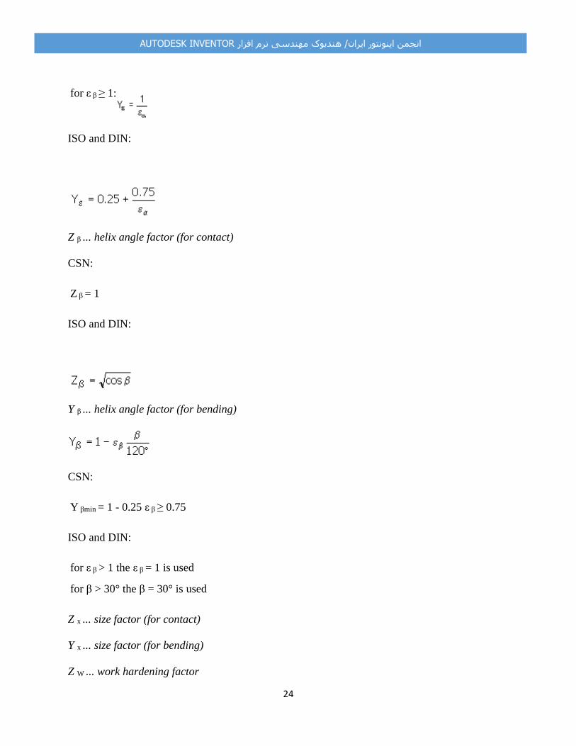
24
AUTODESK INVENTORانجمن اینونتور ایران/ هندبوک مهندسی نرم افزار
for ε β ≥ 1:
ISO and DIN:
Z β ... helix angle factor (for contact)
CSN:
Z β = 1
ISO and DIN:
Y β ... helix angle factor (for bending)
CSN:
Y βmin = 1 - 0.25 ε β ≥ 0.75
ISO and DIN:
for ε β > 1 the ε β = 1 is used
for β > 30° the β = 30° is used
Z x ... size factor (for contact)
Y x ... size factor (for bending)
Z W ... work hardening factor

25
AUTODESK INVENTORانجمن اینونتور ایران/ هندبوک مهندسی نرم افزار
Y Fa ... form factor
where:
h Fa bending arm of a force acting on the tooth end
s Fn thickness of dedendum dangerous section of alternate gear
α Fan bending angle at the end of straight tooth of alternate gear
Y Sa ... stress correction factor
Y Sa = (1.2 + 0.13 L a ) q s exp
Y Sag ... teeth with grinding notches factor
Y δ ... notch sensitivity factor (depends on the material and curvature radius of dedendum
transition)
Y R ... tooth root surface factor

26
AUTODESK INVENTORانجمن اینونتور ایران/ هندبوک مهندسی نرم افزار
K H ... additional loads factor (for contact)
K H = K A K Hv K Hb K Ha
K F ... additional loads factor (for bending)
K F = K A K Fv K Fb K Fa
K A ... application factor (external dynamic forces)
K Hv ... dynamic factor (internal dynamic forces) for contact
K Fv ... dynamic factor (internal dynamic forces) for bending
for CSN:
at K A F t / b w < 150 considering K A F t / b w = 150
for ISO and DIN:
at K A F t / b w < 100 considering K A F t / b w = 100
where: K P , K Q ... table values
K Hβ ... face load factor (for contact)
for CSN:
where:
c = 0.4 gears with hardened tooth sides
c = 0.3 non-hardened gears
f ky = | f sh1 + f sh2 | + f kZ - y β

27
AUTODESK INVENTORانجمن اینونتور ایران/ هندبوک مهندسی نرم افزار
f b , f x , f y ... teeth tolerance
y β ... table value
for ISO and DIN:
for
otherwise ( < 1):
F βy = F βx χ β
for gears with hardened tooth sides χ β = 0.85
for others
F βx = 1.33 f sh + f ma
q' = 0.04723 + 0.15551/z v1 + 0.25791/z v2 - 0.00635 x 1 - 0.11654 x 1 /z v1 - 0.00193 x 2 - 0.24188
x 2 /z v2 + 0.00529 x 1 2 + 0.00182 x 2
2
for F t K A / b w < 100 the values are interpolated
for ISO c' = c' [(F t K A / b w ) / 100] 0.25
for DIN c' = c' (F t K A / b w ) / 100
C M = 0.8
C R = 1 for solid gears
C B = [1 + 0.5 (1.2 - h f /m)] [1 - 0.02 (20° - α)]

28
AUTODESK INVENTORانجمن اینونتور ایران/ هندبوک مهندسی نرم افزار
E steel = 206 000
c γ = c' (0.75 ε α + 0.25)
A, B ... table values depend on the arrangement of teeth gears, shafts, and bearings
K Fβ ... face load factor (for bending)
K Fβ = (K Hβ ) NF
where:
h = 2 m/ε α spur gears
h = 2 m helical gears
K Fa ... transverse load factor (for bending)
for ε γ < 2:
for ε γ > 2:
at K A F t / b w < 100 considering K A F t / b w = 100
limit values:
for CSN: 1 ≤ K Fα ≤ε γ

29
AUTODESK INVENTORانجمن اینونتور ایران/ هندبوک مهندسی نرم افزار
K Hα ... transverse load factor (for contact)
for CSN:
K Hα = 1 for straight teeth
K Hα = K Fα for helical teeth
DIN and ISO:
K Hα = K Fα
for limit values:

30
AUTODESK INVENTORانجمن اینونتور ایران/ هندبوک مهندسی نرم افزار
Strength Calculation according to ANSI/AGMA 2001-D04:2005
Based on the fixed-end beam calculation. Includes the majority of effects.
Safety factor of contact fatigue
where:
s ac allowable contact stress number (material property)
F t tangential force acting at teeth
d w1 operating pitch diameter of pinion
b w operating tooth width
Safety factor of bending fatigue
where:
s at allowable bending stress
P t tangential diametral pitch
b wF1,2 = min (b 1,2 , b w + 2m) operating tooth width
Factor Calculations
31
AUTODESK INVENTORانجمن اینونتور ایران/ هندبوک مهندسی نرم افزار
where:
μ
Poisson's ratio (material property)
E modulus of elasticity (material property)
I geometry factor for pitting resistance
Z N stress cycle factor for pitting resistance
C H hardness ratio factor
K o overload factor
K v dynamic factor
K s size factor
K m load distribution factor K m = 1 + C mc (C pf C pm + C ma C e )
C mc - Lead Correction Factor
C pf - Pinion proportion factor
C ma - Mesh Alignment Factor
C e - Mesh Alignment Correction Factor
J geometry factor for bending strength
Y N stress cycle factor for bending strength
Y a reverse loadingfactor
C f surface condition factor
K R reliability factor
K T temperature factor
K B rim thickness factor
------------------------------------------------------------------------------------------------------------------------------------------
-----------------------------------------------------------------------------------------------------------------------------------------
Web: www.irinventor.ir Email: [email protected] & [email protected] Tel: 09352191813 & 021-46088862

32
AUTODESK INVENTORانجمن اینونتور ایران/ هندبوک مهندسی نرم افزار