Embed Size (px)
Citation preview
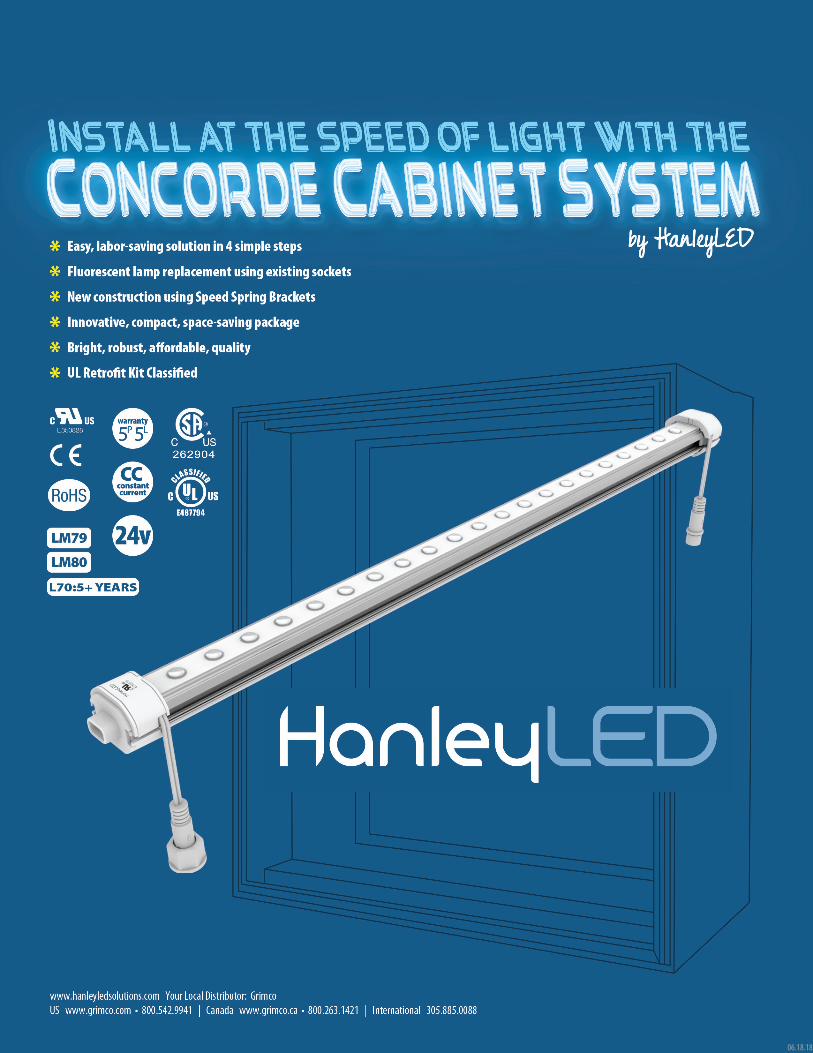
06.18.18
2
READ THESE INSTRUCTIONS COMPLETELY AND CAREFULLY
24v Power Supply Speed Spring Bracket Set(Spring and stationary)
Optional
Concorde Cable Connectors Optional
Retrofit (RF) ConnectorWatertight End Cap Concorde Joint
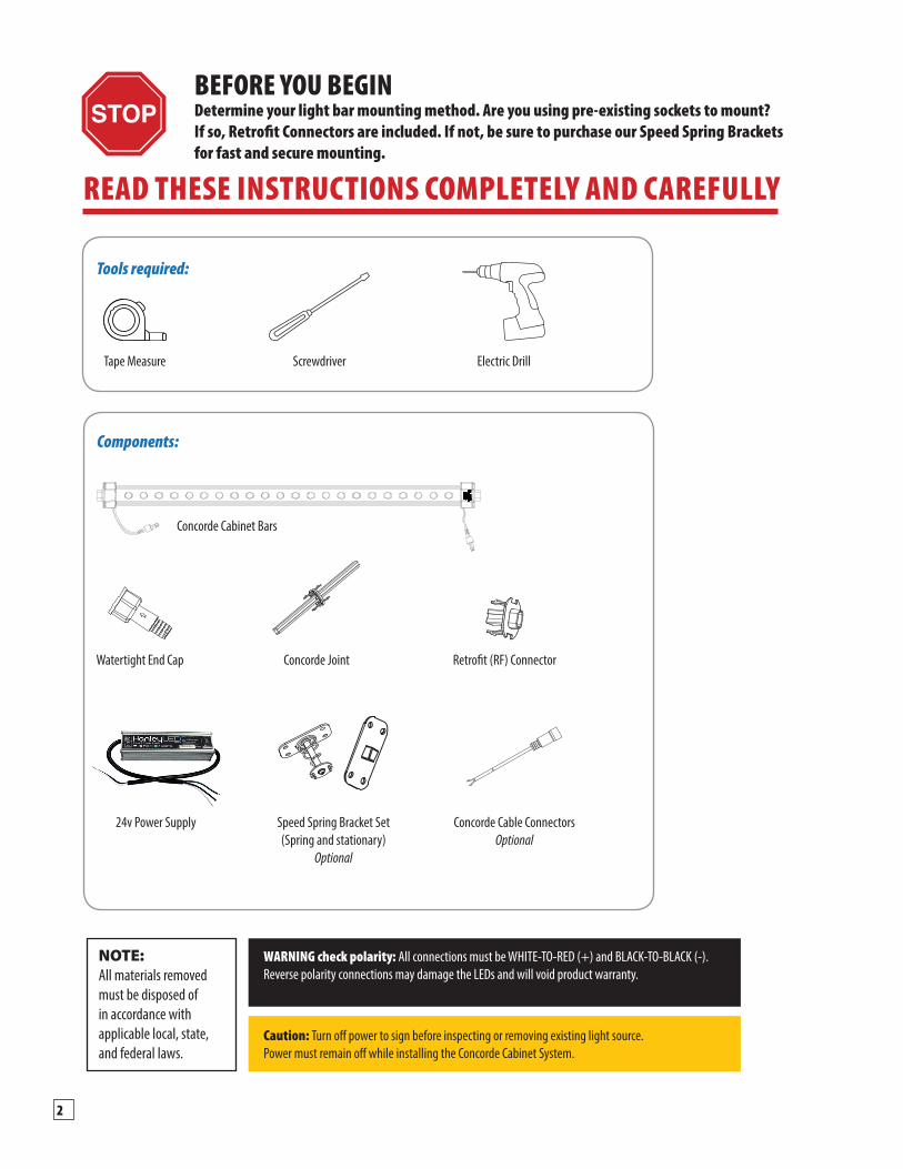
Tools required:
Components:
NOTE:All materials removed must be disposed of in accordance with applicable local, state, and federal laws.
WARNING check polarity: All connections must be WHITE-TO-RED (+) and BLACK-TO-BLACK (-). Reverse polarity connections may damage the LEDs and will void product warranty.
Caution: Turn off power to sign before inspecting or removing existing light source. Power must remain off while installing the Concorde Cabinet System.
Screwdriver Electric DrillTape Measure
BEFORE YOU BEGINDetermine your light bar mounting method. Are you using pre-existing sockets to mount? If so, Retrofit Connectors are included. If not, be sure to purchase our Speed Spring Brackets for fast and secure mounting.
Concorde Cabinet Bars
3Installation Guide | www.hanleyledsolutions.com | 800.542.9941
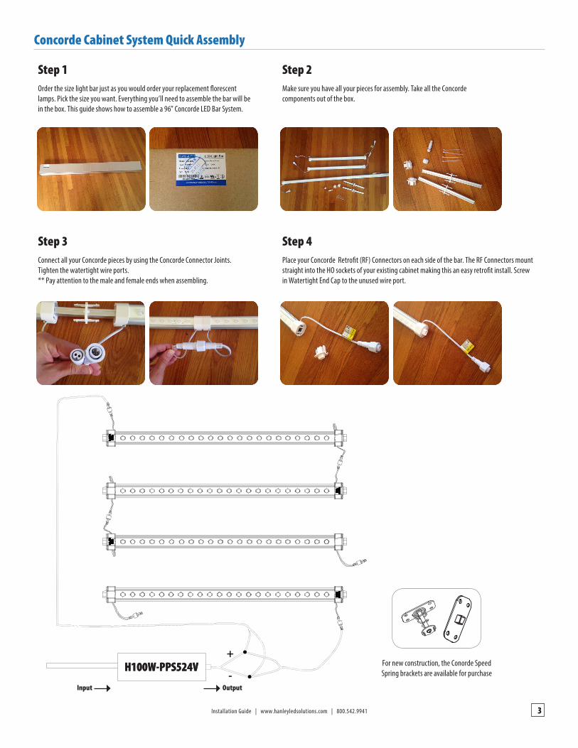
Concorde Cabinet System Quick Assembly
Step 1
Step 3
Step 2
Step 4
Order the size light bar just as you would order your replacement florescent lamps. Pick the size you want. Everything you’ll need to assemble the bar will be in the box. This guide shows how to assemble a 96” Concorde LED Bar System.
Connect all your Concorde pieces by using the Concorde Connector Joints. Tighten the watertight wire ports. ** Pay attention to the male and female ends when assembling.
Make sure you have all your pieces for assembly. Take all the Concorde components out of the box.
Place your Concorde Retrofit (RF) Connectors on each side of the bar. The RF Connectors mount straight into the HO sockets of your existing cabinet making this an easy retrofit install. Screw in Watertight End Cap to the unused wire port.
For new construction, the Conorde SpeedSpring brackets are available for purchase
Input Output
4
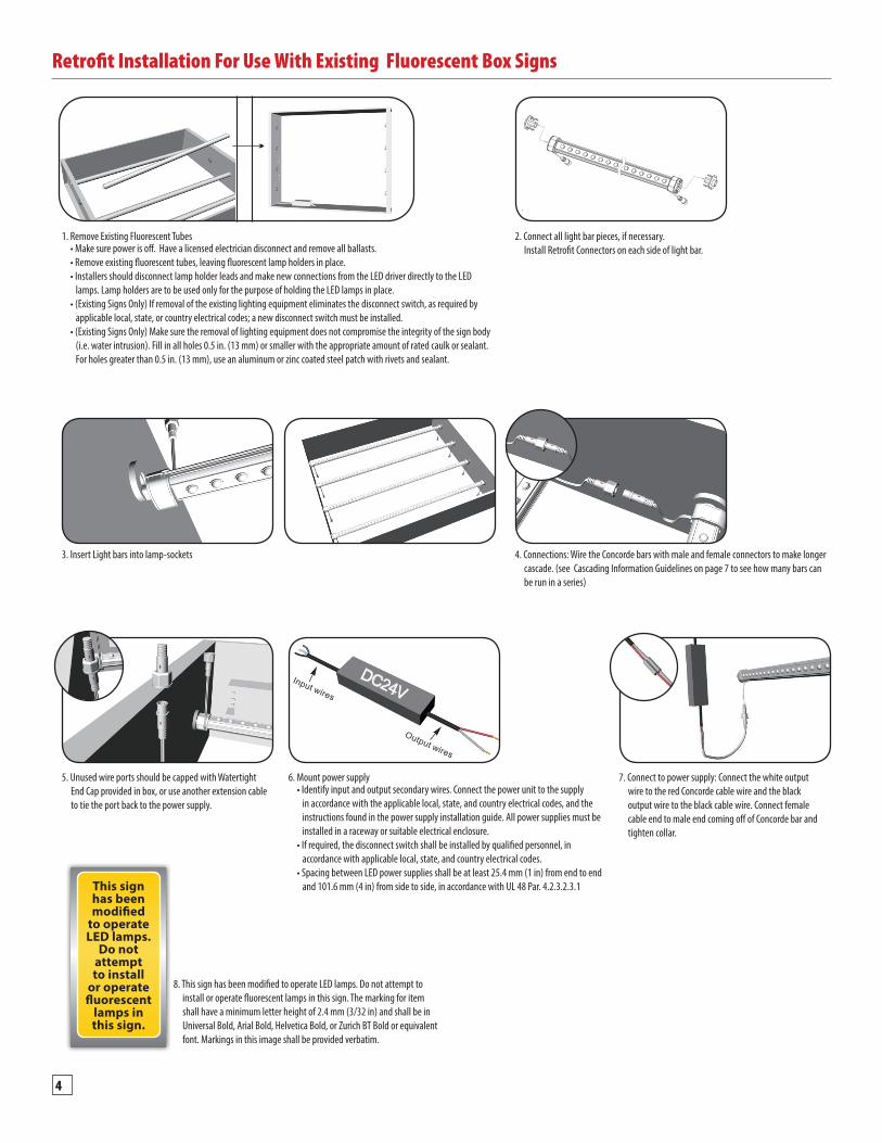
Retrofit Installation For Use With Existing Fluorescent Box Signs
1. Remove Existing Fluorescent Tubes 2. Connect all light bar pieces, if necessary. Install Retrofit Connectors on each side of light bar.• Make sure power is off. Have a licensed electrician disconnect and remove all ballasts.
• Remove existing fluorescent tubes, leaving fluorescent lamp holders in place.• Installers should disconnect lamp holder leads and make new connections from the LED driver directly to the LED lamps. Lamp holders are to be used only for the purpose of holding the LED lamps in place.• (Existing Signs Only) If removal of the existing lighting equipment eliminates the disconnect switch, as required by applicable local, state, or country electrical codes; a new disconnect switch must be installed. • (Existing Signs Only) Make sure the removal of lighting equipment does not compromise the integrity of the sign body (i.e. water intrusion). Fill in all holes 0.5 in. (13 mm) or smaller with the appropriate amount of rated caulk or sealant. For holes greater than 0.5 in. (13 mm), use an aluminum or zinc coated steel patch with rivets and sealant.
4. Connections: Wire the Concorde bars with male and female connectors to make longer cascade. (see Cascading Information Guidelines on page 7 to see how many bars can be run in a series)
3. Insert Light bars into lamp-sockets
6. Mount power supply5. Unused wire ports should be capped with Watertight End Cap provided in box, or use another extension cable to tie the port back to the power supply.
7. Connect to power supply: Connect the white output wire to the red Concorde cable wire and the black output wire to the black cable wire. Connect female cable end to male end coming off of Concorde bar and tighten collar.
• Identify input and output secondary wires. Connect the power unit to the supply in accordance with the applicable local, state, and country electrical codes, and the instructions found in the power supply installation guide. All power supplies must be installed in a raceway or suitable electrical enclosure. • If required, the disconnect switch shall be installed by qualified personnel, in accordance with applicable local, state, and country electrical codes. • Spacing between LED power supplies shall be at least 25.4 mm (1 in) from end to end and 101.6 mm (4 in) from side to side, in accordance with UL 48 Par. 4.2.3.2.3.1
8. This sign has been modified to operate LED lamps. Do not attempt to install or operate fluorescent lamps in this sign. The marking for item shall have a minimum letter height of 2.4 mm (3/32 in) and shall be in Universal Bold, Arial Bold, Helvetica Bold, or Zurich BT Bold or equivalent font. Markings in this image shall be provided verbatim.
This sign has been modified
to operate LED lamps.
Do not attempt to install
or operate fluorescent
lamps in this sign.
5Installation Guide | www.hanleyledsolutions.com | 800.542.9941
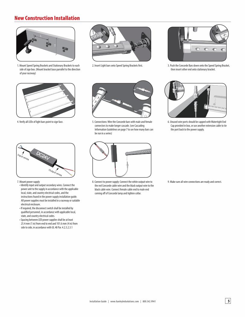
New Construction Installation
4. Verify all LEDs of light bars point to sign face. 5. Connections: Wire the Concorde bars with male and female connectors to make longer cascade. (see Cascading Information Guidelines on page 7 to see how many bars can be run in a series)
6. Unused wire ports should be capped with Watertight End Cap provided in box, or use another extension cable to tie the port back to the power supply.
8. Connect to power supply: Connect the white output wire to the red Concorde cable wire and the black output wire to the black cable wire. Connect female cable end to male end coming off of Concorde lamp and tighten collar.
9. Make sure all wire connections are ready and correct.
1. Mount Speed Spring Brackets and Stationary Brackets to each side of sign box. (Mount bracket base parrallel to the direction of your raceway)
2. lnsert Light bars onto Speed Spring Brackets first. 3. Push the Concorde Bars down onto the Speed Spring Bracket, then insert other end onto stationary bracket.
7. Mount power supply• Identify input and output secondary wires. Connect the power unit to the supply in accordance with the applicable local, state, and country electrical codes, and the instructions found in the power supply installation guide. All power supplies must be installed in a raceway or suitable electrical enclosure. • If required, the disconnect switch shall be installed by qualified personnel, in accordance with applicable local, state, and country electrical codes. • Spacing between LED power supplies shall be at least 25.4 mm (1 in) from end to end and 101.6 mm (4 in) from side to side, in accordance with UL 48 Par. 4.2.3.2.3.1
6
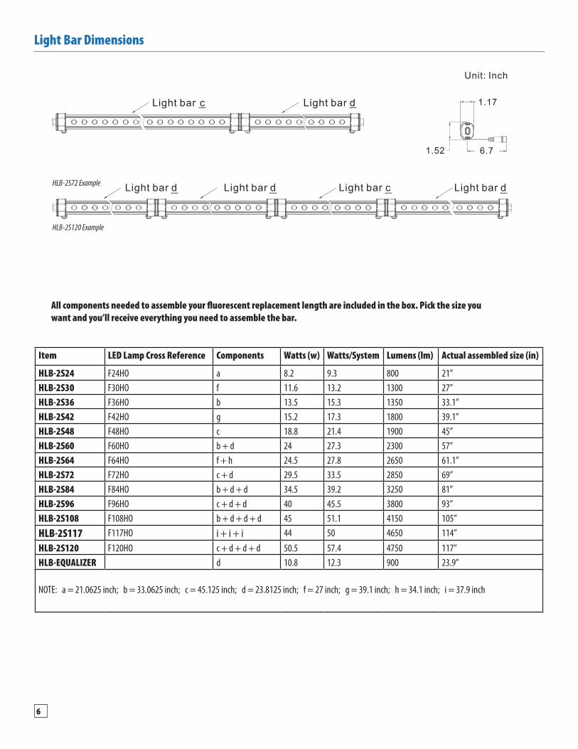
Light Bar Dimensions
All components needed to assemble your fluorescent replacement length are included in the box. Pick the size you want and you’ll receive everything you need to assemble the bar.
HLB-2S72 Example
HLB-2S120 Example
Item LED Lamp Cross Reference Components Watts (w) Watts/System Lumens (lm) Actual assembled size (in)
HLB-2S24 F24HO a 8.2 9.3 800 21”HLB-2S30 F30HO f 11.6 13.2 1300 27”HLB-2S36 F36HO b 13.5 15.3 1350 33.1”HLB-2S42 F42HO g 15.2 17.3 1800 39.1”HLB-2S48 F48HO c 18.8 21.4 1900 45”HLB-2S60 F60HO b + d 24 27.3 2300 57”HLB-2S64 F64HO f + h 24.5 27.8 2650 61.1”HLB-2S72 F72HO c + d 29.5 33.5 2850 69”HLB-2S84 F84HO b + d + d 34.5 39.2 3250 81”HLB-2S96 F96HO c + d + d 40 45.5 3800 93”HLB-2S108 F108HO b + d + d + d 45 51.1 4150 105”HLB-2S117 F117HO i + i + i 44 50 4650 114”HLB-2S120 F120HO c + d + d + d 50.5 57.4 4750 117”HLB-EQUALIZER d 10.8 12.3 900 23.9”
NOTE: a = 21.0625 inch; b = 33.0625 inch; c = 45.125 inch; d = 23.8125 inch; f = 27 inch; g = 39.1 inch; h = 34.1 inch; i = 37.9 inch
7Installation Guide | www.hanleyledsolutions.com | 800.542.9941
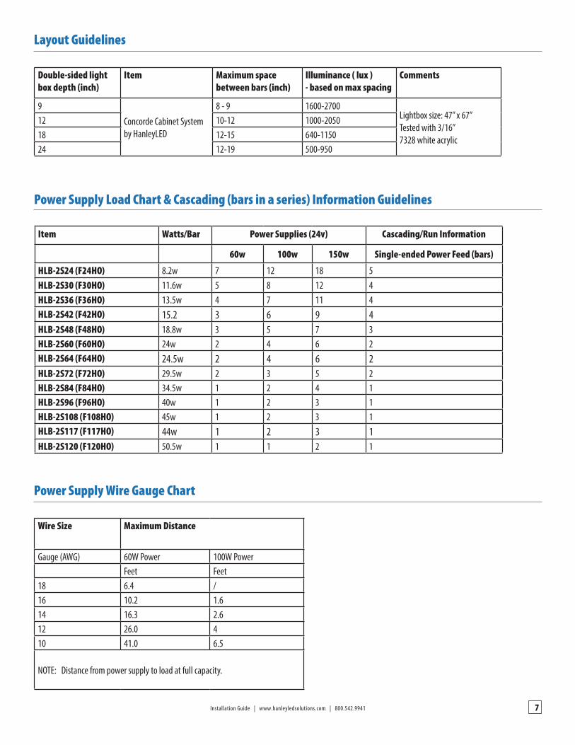
Layout Guidelines
Power Supply Wire Gauge Chart
Power Supply Load Chart & Cascading (bars in a series) Information Guidelines
Double-sided light box depth (inch)
Item Maximum space between bars (inch)
Illuminance ( lux )- based on max spacing
Comments
9
Concorde Cabinet Systemby HanleyLED
8 - 9 1600-2700Lightbox size: 47” x 67”Tested with 3/16” 7328 white acrylic
12 10-12 1000-205018 12-15 640-115024 12-19 500-950
Wire Size Maximum Distance
Gauge (AWG) 60W Power 100W PowerFeet Feet
18 6.4 /16 10.2 1.614 16.3 2.612 26.0 410 41.0 6.5
NOTE: Distance from power supply to load at full capacity.
Item Watts/Bar Power Supplies (24v) Cascading/Run Information
60w 100w 150w Single-ended Power Feed (bars)
HLB-2S24 (F24HO) 8.2w 7 12 18 5HLB-2S30 (F30HO) 11.6w 5 8 12 4HLB-2S36 (F36HO) 13.5w 4 7 11 4HLB-2S42 (F42HO) 15.2 3 6 9 4HLB-2S48 (F48HO) 18.8w 3 5 7 3HLB-2S60 (F60HO) 24w 2 4 6 2HLB-2S64 (F64HO) 24.5w 2 4 6 2HLB-2S72 (F72HO) 29.5w 2 3 5 2HLB-2S84 (F84HO) 34.5w 1 2 4 1HLB-2S96 (F96HO) 40w 1 2 3 1HLB-2S108 (F108HO) 45w 1 2 3 1HLB-2S117 (F117HO) 44w 1 2 3 1HLB-2S120 (F120HO) 50.5w 1 1 2 1
8
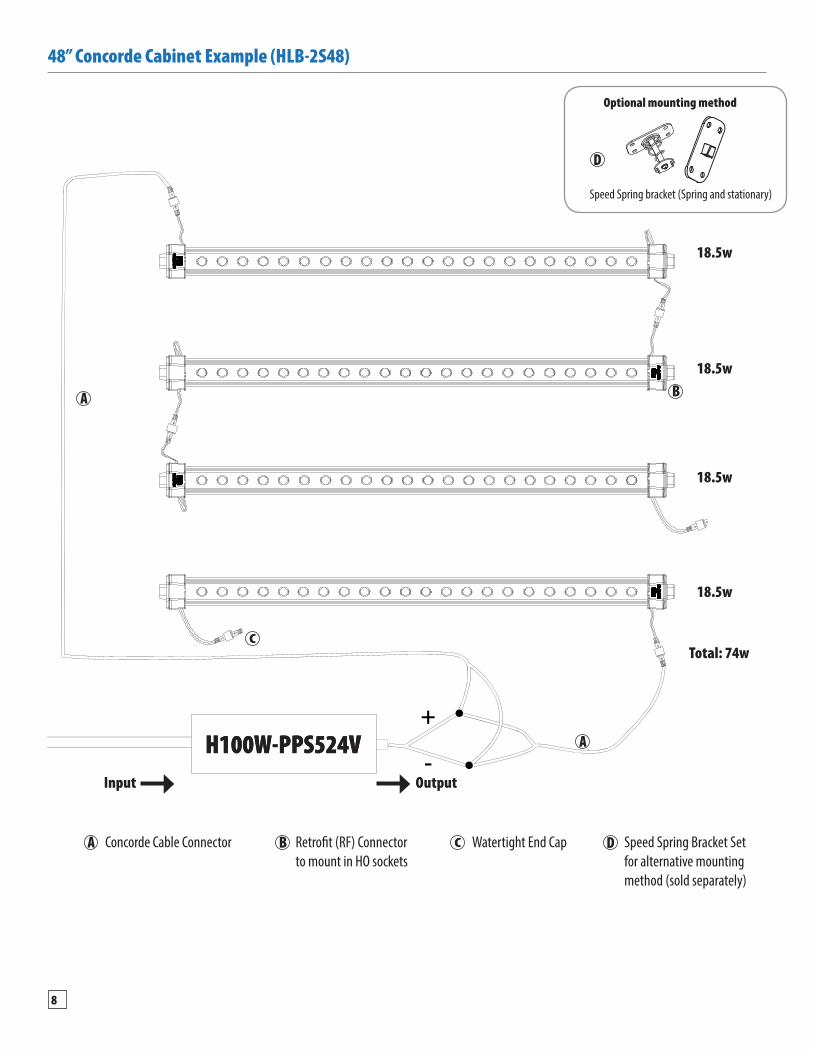
Speed Spring bracket (Spring and stationary)
18.5w
18.5w
18.5w
18.5w
Total: 74w
48” Concorde Cabinet Example (HLB-2S48)
Optional mounting method
Input Output
Concorde Cable Connector Retrofit (RF) Connector to mount in HO sockets
Watertight End Cap Speed Spring Bracket Set for alternative mounting method (sold separately)
9Installation Guide | www.hanleyledsolutions.com | 800.542.9941
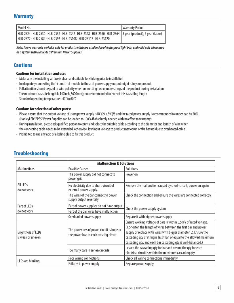
Warranty
Cautions
Troubleshooting
Model No. Warranty Period HLB-2S24 · HLB-2S30 · HLB-2S36 · HLB-2S42 · HLB-2S48 · HLB-2S60 · HLB-2S64 HLB-2S72 · HLB-2S84 · HLB-2S96 · HLB-2S108 · HLB-2S117 · HLB-2S120
5 year (product), 5 year (labor)
Note: Above warranty period is only for products which are used inside of waterproof light box, and valid only when used as a system with HanleyLED Premium Power Supplies.
Cautions for installation and use:- Make sure the installing surface is clean and suitable for sticking prior to installation- Inadequately connecting the ‘+’ and ‘-’ of module to those of power supply output might ruin your product- Full attention should be paid to wire polarity when connecting two or more strings of the product during installation- The maximum cascade length is 142inch[3600mm]; not recommended to exceed this cascading length- Standard operating temperature: -40° to 60°C
Cautions for selection of other parts:- Please ensure that the output voltage of using power supply is DC (24±5%)V, and the rated power supply is recommended to underload by 20%. (HanleyLED “PPS5” Power Supplies can be loaded to 100% if absolutely needed with no effect to warranty) - During installation, please ask qualified person to count and select the suitable cable according to the diameter and length of wire when the connecting cable needs to be extended, otherwise, low input voltage to product may occur, or fire hazard due to overheated cable - Prohibited to use any acid or alkaline glue to fix this product
Malfunction & SolutionsMalfunctions Possible Causes Solutions
All LEDs do not work
The power supply did not connect to power grid
Power on
No electricity due to short-circuit of external power supply.
Remove the malfunction caused by short-circuit, power on again
The wires of the bar connect to power supply output reversely
Check the connection and ensure the wires are connected correctly
Part of LEDs do not work
Part of power supplies do not have outputCheck the power supply system
Part of the bar wires have malfunction
Brightness of LEDs is weak or uneven
0verloaded power supply Replace it with higher power supply
The power loss of power circuit is huge or the power loss to each existing circuit
Ensure working voltage of bars is within ±5%V of rated voltage. (1.Shorten the length of wires between the first bar and power supply or replace with wires with bigger diameter; 2. Ensure the cascading qty of string is less than or equal to the allowed maximum cascading qty, and each bar cascading qty is well-balanced.)
Too many bars in series/cascadeLessen the cascading qty for bar and ensure the qty for each electrical circuit is within the maximum cascading qty
LEDs are blinkingPoor wiring connections Check all wiring connections immediatlyFailures in power supply Replace power supply