Embed Size (px)
Citation preview

L854227107/2011 rev 3
BOB 50M
BOB 50ME
UNIONE NAZIONALE COSTRUTTORIAUTOMATISMI PER CANCELLI, PORTE
SERRANDE ED AFFINI
3
45
5 /
48
5 /
52
0
85
7
10
0
87
48
70
10
7
98
0
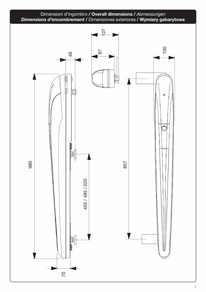
Dimensioni d’ingombro / Overall dimensions / AbmessungenDimensions d’encombrement / Dimensiones exteriores / Wymiary gabarytowe
4
1
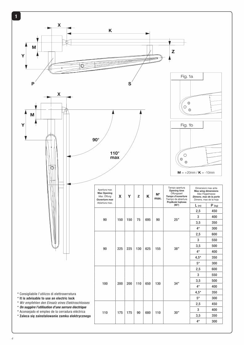
Apertura max
Max OpeningMax. Öffung
Ouverture max
Abiertura max.
X Y Z K M*max.
Tempo aperturaOpening time
ÖffungszeitTemps d'ouverture
Tiempo de abierturaPrędkość kątowa
(90°)
Dimensioni max antaMax wing dimensions
Max FlügelmasseDimens. max de la porte
Dimens. max de la hoja
L (m) P (kg)
90 150 150 75 695 90 25”
2,5 450
3 400
3,5 350
4* 300
90 225 225 130 625 155 38”
2,5 600
3 550
3,5 500
4* 400
4,5* 350
5* 300
100 200 200 110 650 130 34”
2,5 600
3 550
3,5 500
4* 400
4,5* 350
5* 300
110 175 175 90 680 110 30”
2,5 450
3 400
3,5 350
4* 300
XK
P S
Y
MZ
M
Y
X
90°
110°max
M = +20mm / K = -10mm
Fig. 1a
Fig. 1b
* Consigliabile l’utilizzo di elettroserratura
* It is advisable to use an electric lock* Wir empfehlen den Einsatz eines Elektroschlosses
* On suggère l’utilisation d’une serrure électrique
* Aconsejado el empleo de la cerradura eléctrica
* Zaleca się zainstalowanie zamka elektrycznego
5
3
2
V1
V2
BB
P
F
D
P
S V
R
C
T
Mettere a livello.Level.Nivellieren.Mettre de niveau.
Nivelar.Ustawić na wysokości
Saldare.Weld.Anschweißen.Souder.
Soldar.Spawać
Saldare.Weld.Anschweißen.Souder.
Soldar.Spawać.
GrassoGrease Fett Graisse
GrasaSmar
6
4
5
VP
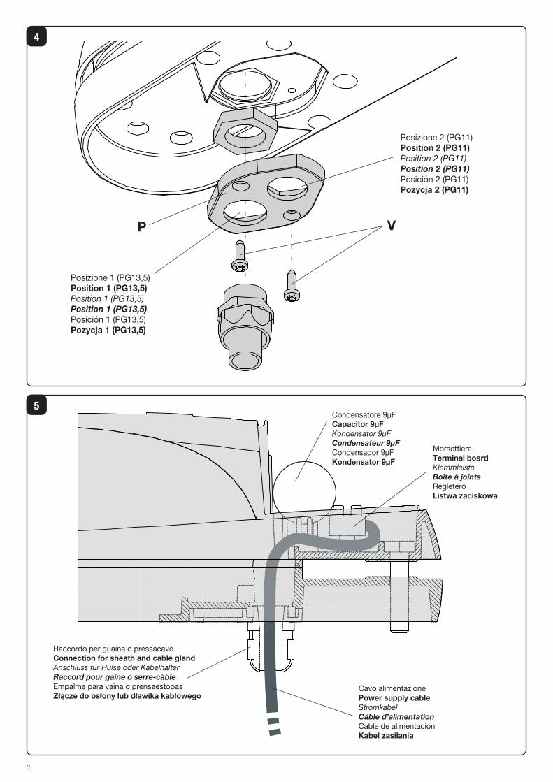
Posizione 2 (PG11)Position 2 (PG11)Position 2 (PG11)Position 2 (PG11)
Posición 2 (PG11)Pozycja 2 (PG11)
Posizione 1 (PG13,5)Position 1 (PG13,5)Position 1 (PG13,5)Position 1 (PG13,5)
Posición 1 (PG13,5)Pozycja 1 (PG13,5)
Condensatore 9μFCapacitor 9μFKondensator 9μFCondensateur 9μF
Condensador 9μFKondensator 9μF
Cavo alimentazionePower supply cableStromkabelCâble d’alimentation
Cable de alimentaciónKabel zasilania
Raccordo per guaina o pressacavoConnection for sheath and cable glandAnschluss für Hülse oder KabelhalterRaccord pour gaine o serre-câble
Empalme para vaina o prensaestopasZłącze do osłony lub dławika kablowego
MorsettieraTerminal boardKlemmleisteBoîte à joints
RegleteroListwa zaciskowa
7
6
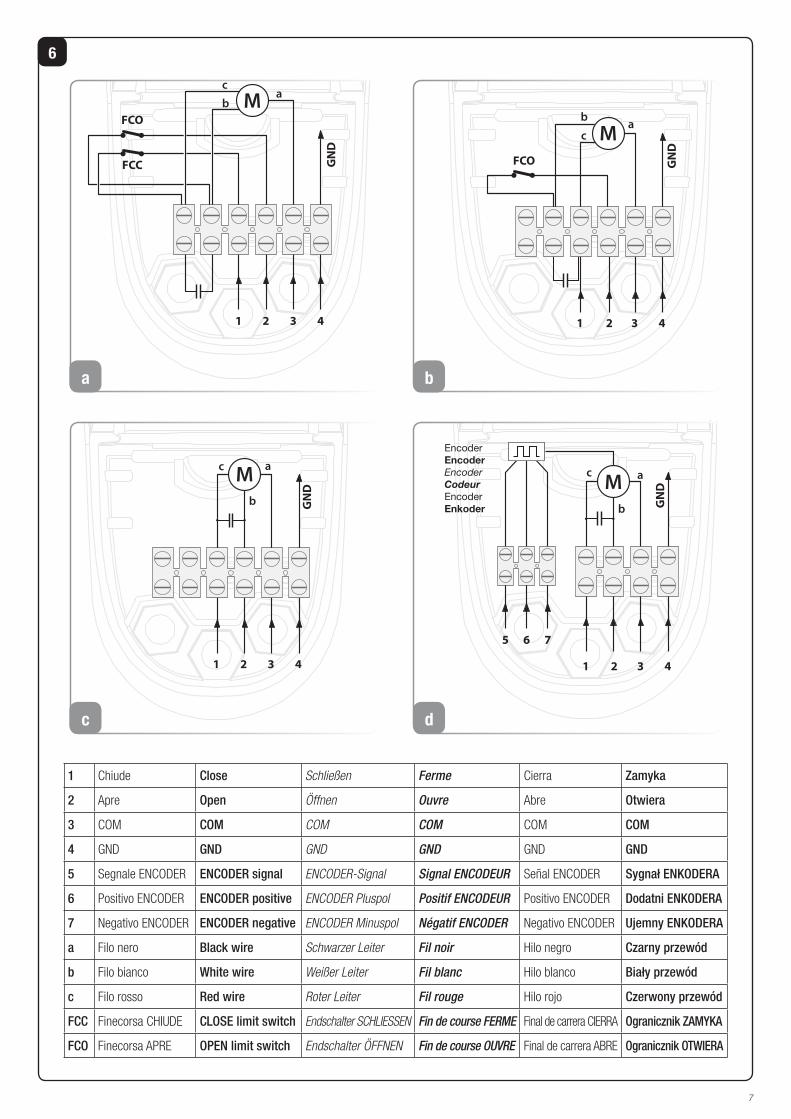
1 Chiude Close Schließen Ferme Cierra Zamyka
2 Apre Open Öffnen Ouvre Abre Otwiera
3 COM COM COM COM COM COM
4 GND GND GND GND GND GND
5 Segnale ENCODER ENCODER signal ENCODER-Signal Signal ENCODEUR Señal ENCODER Sygnał ENKODERA
6 Positivo ENCODER ENCODER positive ENCODER Pluspol Positif ENCODEUR Positivo ENCODER Dodatni ENKODERA
7 Negativo ENCODER ENCODER negative ENCODER Minuspol Négatif ENCODER Negativo ENCODER Ujemny ENKODERA
a Filo nero Black wire Schwarzer Leiter Fil noir Hilo negro Czarny przewód
b Filo bianco White wire Weißer Leiter Fil blanc Hilo blanco Biały przewód
c Filo rosso Red wire Roter Leiter Fil rouge Hilo rojo Czerwony przewód
FCC Finecorsa CHIUDE CLOSE limit switch Endschalter SCHLIESSEN Fin de course FERME Final de carrera CIERRA Ogranicznik ZAMYKA
FCO Finecorsa APRE OPEN limit switch Endschalter ÖFFNEN Fin de course OUVRE Final de carrera ABRE Ogranicznik OTWIERA
M
1
ba
c
2 3 4GND
FCO
FCC
a
ba
c
FCO
2 3
GND
41
M
b
M
b
ac
1 2 3 4
GND
c
1 2 3 4
a
b
c
5 6 7
GNDM
Encoder
Encoder
Encoder
Codeur
Encoder
Enkoder
d
8
3 4
2
1
5
3x1,5 min.
230Vac
2
1
2x1,
52x
0,5
2x0,5
4x1
4x1
3x0,5*
3x0,5*
4x0,5
RG
58
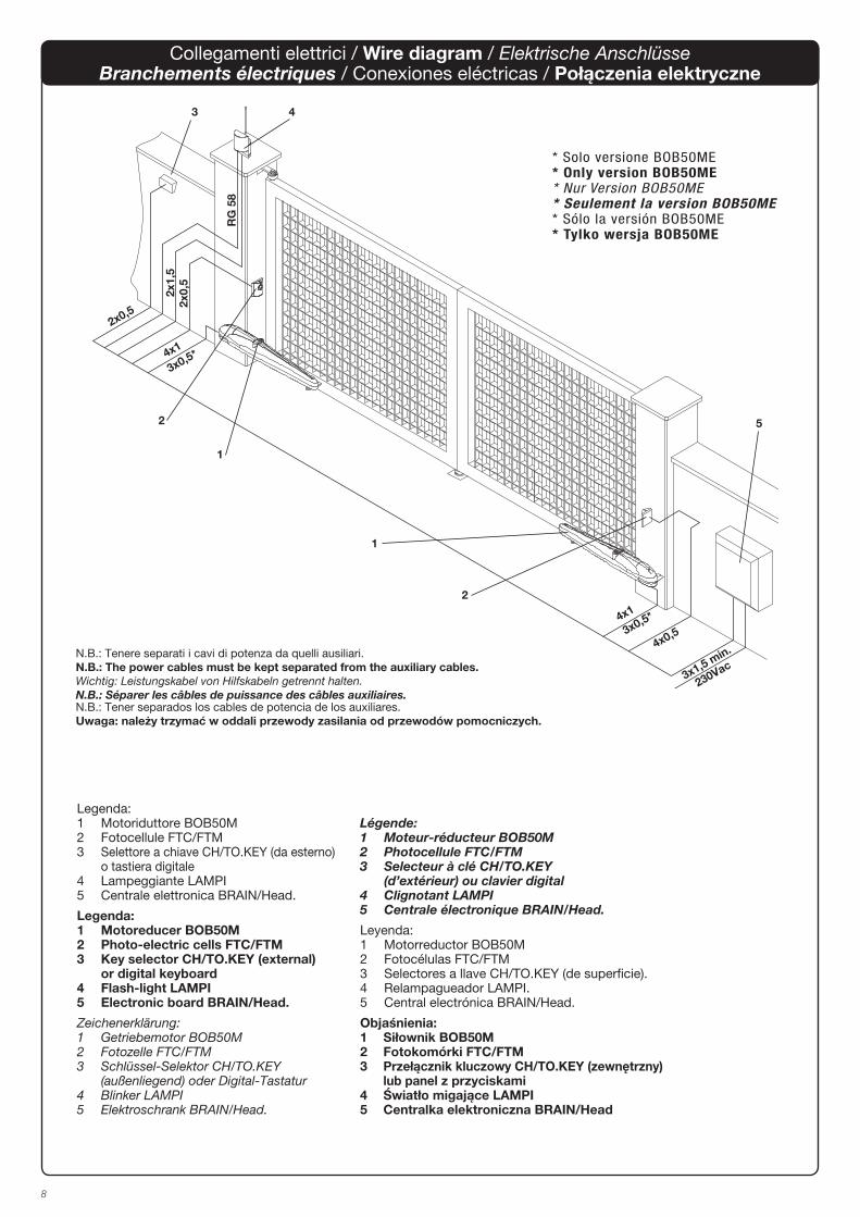
Légende:1 Moteur-réducteur BOB50M2 Photocellule FTC/FTM3 Selecteur à clé CH/TO.KEY (d’extérieur) ou clavier digital4 Clignotant LAMPI5 Centrale électronique BRAIN/Head.
Leyenda:1 Motorreductor BOB50M2 Fotocélulas FTC/FTM3 Selectores a llave CH/TO.KEY (de superficie).4 Relampagueador LAMPI.5 Central electrónica BRAIN/Head.
Objaśnienia:1 Siłownik BOB50M2 Fotokomórki FTC/FTM3 Przełącznik kluczowy CH/TO.KEY (zewnętrzny) lub panel z przyciskami4 Światło migające LAMPI5 Centralka elektroniczna BRAIN/Head
Legenda:1 Motoriduttore BOB50M2 Fotocellule FTC/FTM3 Selettore a chiave CH/TO.KEY (da esterno) o tastiera digitale4 Lampeggiante LAMPI5 Centrale elettronica BRAIN/Head.
Legenda:1 Motoreducer BOB50M2 Photo-electric cells FTC/FTM3 Key selector CH/TO.KEY (external) or digital keyboard4 Flash-light LAMPI5 Electronic board BRAIN/Head.
Zeichenerklärung:1 Getriebemotor BOB50M2 Fotozelle FTC/FTM3 Schlüssel-Selektor CH/TO.KEY (außenliegend) oder Digital-Tastatur4 Blinker LAMPI5 Elektroschrank BRAIN/Head.
Collegamenti elettrici / Wire diagram / Elektrische AnschlüsseBranchements électriques / Conexiones eléctricas / Połączenia elektryczne
* Solo versione BOB50ME* Only version BOB50ME* Nur Version BOB50ME* Seulement la version BOB50ME* Sólo la versión BOB50ME* Tylko wersja BOB50ME
N.B.: Tenere separati i cavi di potenza da quelli ausiliari.
N.B.: The power cables must be kept separated from the auxiliary cables.Wichtig: Leistungskabel von Hilfskabeln getrennt halten.N.B.: Séparer les câbles de puissance des câbles auxiliaires.N.B.: Tener separados los cables de potencia de los auxiliares.
Uwaga: należy trzymać w oddali przewody zasilania od przewodów pomocniczych.

11
WARNINGThe product shall not be used for purposes or in ways
other than those for which the product is intended for and
as described in this manual. Incorrect uses can damage
the product and cause injuries and damages.
The company shall not be deemed responsible for the
non-compliance with a good manufacture technique of
gates as well as for any deformation, which might occur
during use.
Keep this manual for further use.
Qualified personnel, in compliance with regulations in
force, shall install the system.
Packaging must be kept out of reach of children, as it can
be hazardous. For disposal, packaging must be divided
the various types of waste (e.g. carton board, polystyrene)
in compliance with regulations in force.
The installer must supply all information on the automatic,
manual and emergency operation of the automatic sy-
stem and supply the end user with instructions for use.
An omnipolar switch/section switch with remote
contact opening equal to, or higher than 3mm
must be provided on the power supply mains..
Make sure that before wiring an adequate differential
switch and an overcurrent protection is provided.
Pursuant to safety regulations in force, some types of in-
stallation require that the gate connection be earthed.
During installation, maintenance and repair, cut off power
supply before accessing to live parts.
Descriptions and figures in this manual are not binding.
While leaving the essential characteristics of the product
unchanged, the manufacturer reserves the right to modify
the same under the technical, design or commercial point
of view without necessarily update this manual.
EC Declaration of Conformity
Manufacturer: Automatismi Benincà SpA.Address: Via Capitello, 45 - 36066 Sandrigo (VI) - Italia
Herewith declares that: the operator for hinged gates model BOB50M / BOB50ME.
is complying with provisions set forth by the following other EC Directive:
- DIRECTIVE 2004/108/EC OF THE EUROPEAN PARLIAMENT AND OF THE COUNCIL
of 15 December 2004, on the harmonisation of the laws of Member States relating to
electromagnetic compatibility and which cancels Directive 89/336/EEC, according to the
following harmonised regulations: EN 61000-6-2:2005, EN 61000-6-3:2007.
- DIRECTIVE 2006/95/EC OF THE EUROPEAN PARLIAMENT AND OF THE COUNCIL of 12
December 2006, on the harmonisation of the laws of Member States relating to electrical
equipment designed for use with certain voltage limits, according to the following harmonised
regulations: EN 60335-1:2002 + A1:2004 + A11:2004 + A12:2006 + A2:2006 + A13:2008;
EN 60335-1-103:2003.
Benincà Luigi, Legal responsible.
Sandrigo, 10/06/2010.

12
Introduction
herein.
item for applications different from those indicated in the instructions herein.
system.The end user should receive special instruction manual.
for damages and injuries caused by manufacture faults. It is however required that the machine bear the CE marking and original Benincà parts be used.
General information To ensure a good operation of these automatic devices, the gate to be automated should meet the following requirements:- good strength and stiffness.- hinges should have a minimum backlash and allow
for smooth and regular manual operations.- when closed, the gate leaves should correctly
overlap for their entire height.
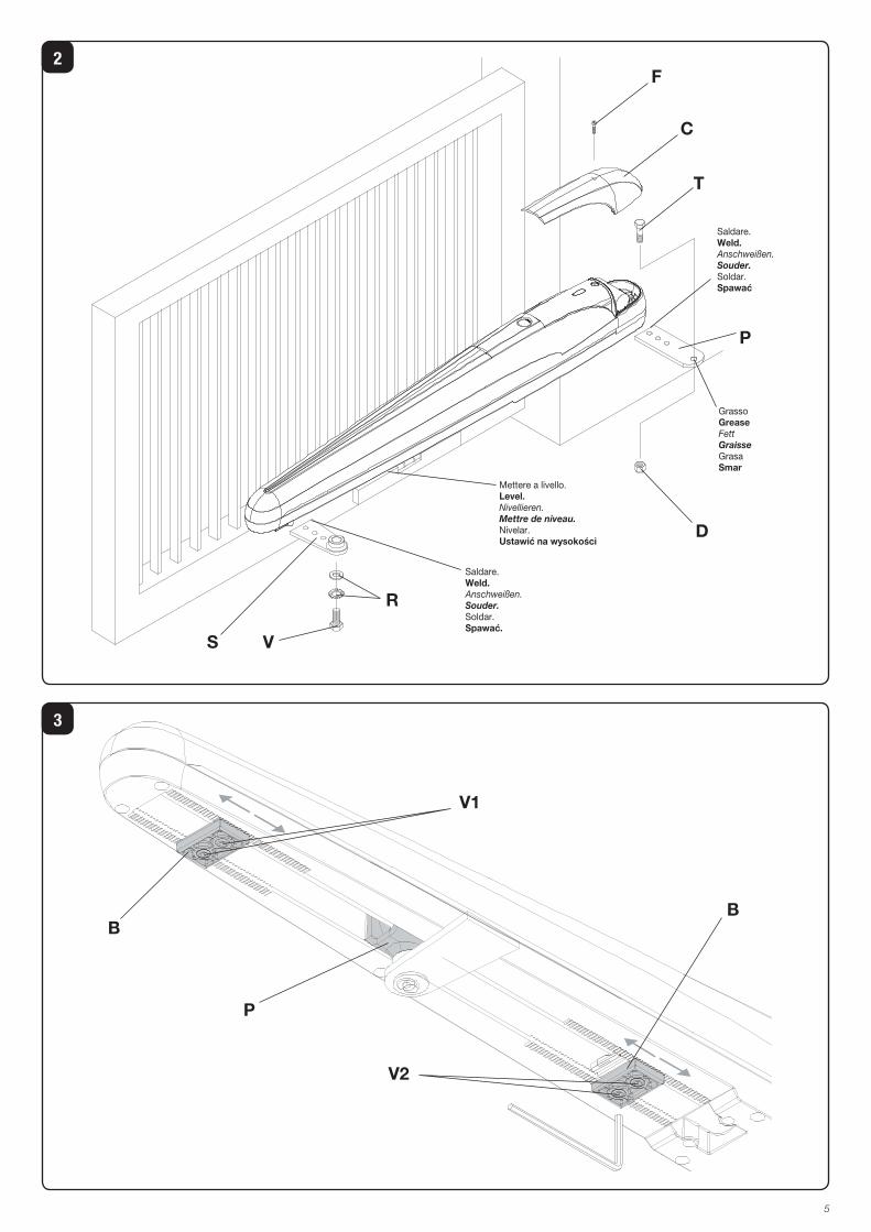
How to install the automatic system Calculate the height of the system from the ground (it is advisable to define a position as much centred as possible with respect to the main door and in correspondence with a strong cross girder). Weld the plate P, following measures in Fig. 1.With the door closed, weld bracket S to a cross beam of the main door or other element with equal strength, according to measures shown in Fig. 1. Keep in mind that, when carrying out this operation, the actuator should not be totally in a stroke end position.Remove the cover C by loosening the screw F. Then fix the actuator to the plate P by means of the screw T and the nut D (Fig. 2). Lock the actuator to plate S by means of screw V and washer R.
The holes in the acturator (Fig. 1a-1b) help to keep to the optimum installation measures.
How to adjust the mechanical stoppersThe actuator is provided with adjustable mechanical stoppers in the opening and closing phases. The system is adjusted by suitably positioning the “Open” and “Close” mechanical locks, as shown hereunder (Fig.3):
1) Unlock the automatic system by using the special release lever, as shown in the instructions for the user (page 21-22).
2) Close the door/gate leaf.
3) Loosen screws V1 and move the “Close” lock until it reaches the pivot P, then tighten screws V1.
4) Open the door/gate leaf.
5) Loosen screws V2 and move the “Open” lock until it reaches the pivot P, then tighten screws V2.
6) Reset the automatic operating mode.
In the BOB 5M version, two limit micro-switches are provided fixed to the mechanical stoppers.The micro-switches trigger slightly in advance with respect to the mechanical stop.
Connections
1) The special plate P (Fig. 4) allows for using a link for sheath or cable gland PG11, or PG13,5. Once the type of cable gland is applied to the plate, fix the latter to the adaptor cover by means of screws V.
2) Insert the cable, or cables, under the terminal board, as shown in Fig.5. This will leave enough space for the capacitor.
3) BOB 5M: carry out the wiring by referring to the wire diagram shown in Fig 6a (use both limit switches). In order to use either the opening limit switch or the mechanical stoppers, change wiring as shown in Fig. 6b (opening limit switch only) or 6c (mechanical stoppers only).
N.B: in wiring connections shown in Fig. 6a and 6b, the capacitor MUST NOT be connected to the control unit, while for wire connection shown in Fig. 6c, the capacitor can be connected to the control unit.
4) BOB 5ME: carry out the wiring by referring to wire diagram shown in Fig 6d.
5) It is mandatory to provide for ground by using the special GND terminal.
WARNINGThe insurance policy, which covers any damages or injuries caused by manufacture faults, requires that the installation comply with regulations in force and Benincà original accessories be used.
TECHNICAL DATA BOB50MBOB50ME
Power supply 230Vac 50/60Hz
Absorbed rating 310 W
Absorbed current 1,4 A
Thrust 3500 N
Jogging 40%
Protection degree IP54
Operating temperature -20°C / +70°C
Capacitor 9 μF
Door leaf max. weight 600 kg
Useful stroke:
- with 2 mechanical stoppers
- with 1 mechanical stopper
- without mechanical stoppers
455 mm485 mm520 mm
Translation speed 0,7 m/min
Noise level <70 dB
Lubrication Permanentgrease
Weight 11,6 kg
21
Libro istruzioni per l’utilizzatore
User’s handbook for the userHandbuch für den VerbraucherManuel d’instructions pour l’utilisateur
Libro de instrucciones para el usuario
Instrukcja obsługi dla użytkownika
Norme di sicurezza
Non lasciare che i bambini giochino con i comandi o in prossimità delle ante.
ma avvertire un tecnico specializzato.
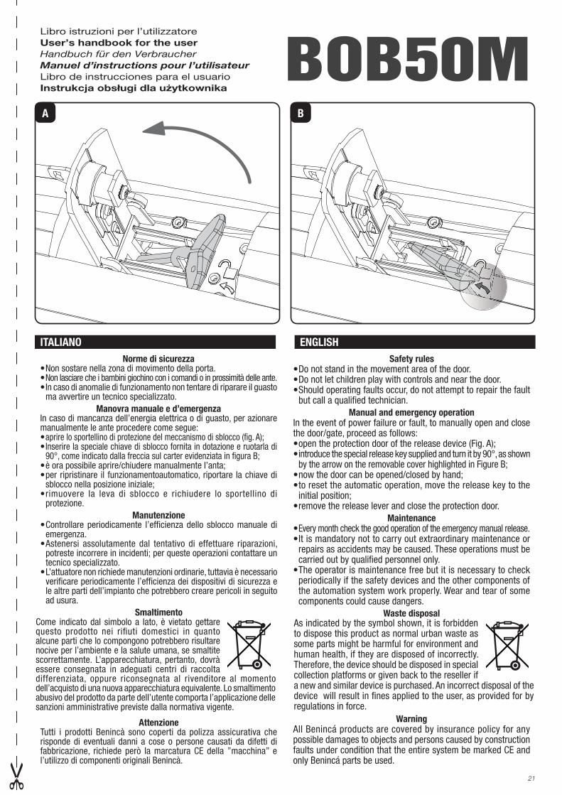
Manovra manuale e d’emergenzaIn caso di mancanza dell’energia elettrica o di guasto, per azionare manualmente le ante procedere come segue:aprire lo sportellino di protezione del meccanismo di sblocco (fig. A); Inserire la speciale chiave di sblocco fornita in dotazione e ruotarla di 90°, come indicato dalla freccia sul carter evidenziata in figura B;
sblocco nella posizione iniziale;
protezione.
Manutenzione
emergenza.
potreste incorrere in incidenti; per queste operazioni contattare un tecnico specializzato.
verificare periodicamente l’efficienza dei dispositivi di sicurezza e le altre parti dell’impianto che potrebbero creare pericoli in seguito ad usura.
Smaltimento
AttenzioneTutti i prodotti Benincà sono coperti da polizza assicurativa che risponde di eventuali danni a cose o persone causati da difetti di fabbricazione, richiede però la marcatura CE della ”macchina” e l’utilizzo di componenti originali Benincà.
Safety rules
but call a qualified technician.
Manual and emergency operationIn the event of power failure or fault, to manually open and close
introduce the special release key supplied and turn it by 90°, as shown by the arrow on the removable cover highlighted in Figure B;
initial position;
MaintenanceEvery month check the good operation of the emergency manual release.
repairs as accidents may be caused. These operations must be carried out by qualified personnel only.
periodically if the safety devices and the other components of the automation system work properly. Wear and tear of some components could cause dangers.
Waste disposal
WarningAll Benincá products are covered by insurance policy for any possible damages to objects and persons caused by construction faults under condition that the entire system be marked CE and only Benincá parts be used.
ITALIANO ENGLISH
BOB50MA B
questo prodotto nei rifiuti domestici in quanto alcune parti che lo compongono potrebbero risultare nocive per l’ambiente e la salute umana, se smaltite scorrettamente. L’apparecchiatura, pertanto, dovrà essere consegnata in adeguati centri di raccolta differenziata, oppure riconsegnata al rivenditore al momento dell’acquisto di una nuova apparecchiatura equivalente. Lo smaltimento abusivo del prodotto da parte dell’utente comporta l’applicazione delle sanzioni amministrative previste dalla normativa vigente.
As indicated by the symbol shown, it is forbidden to dispose this product as normal urban waste as some parts might be harmful for environment and human health, if they are disposed of incorrectly. Therefore, the device should be disposed in special collection platforms or given back to the reseller if a new and similar device is purchased. An incorrect disposal of the device will result in fines applied to the user, as provided for by regulations in force.

23
n° BOB50M / BOB50ME
Denominazione - Description - Bezeichnung - Dénomination - Denominación - OkreślenieCod.
1 Copertura plastica Plastic cover Plastikabdeckungen Couverture plast. Cubierta de plástico Obudowy Plastykowe 9686630
2 Leva di sblocco Release lever Entriegelungshebel Levier de déblocage Palanca de desbloq. Dźwig. odblokowująca 9686631
3 Gruppo sblocco Unblock. group Ent. Gruppe Déblocage Desbloqueo Zespół odblok. 9686632
4 Blister Blister Blister Blister Blister Blister 9686633
5 Motore Motor Motor Moteur Motor Silnik 9686634
6 Carter superiore Upper cover Gehäuse Carter Cárter Karter 9686635
7 Ingranaggio di riduzione Gear Zahnrad Engranage Engranaje Koło zębate 9686636
8 Vite senza fine Worm screw Welle Vis sans fin Tornillo sin fin Śruba dwustronna 9686637
9 Perno di sblocco Lock with pin Entblockung Plaque avec pivot Bloqueo Chwytak blok. 9686638
10 Carter inferiore Lower cover Gehäuse Carter Cárter Karter 9686639
11 Finecorsa
(solo BOB 5M)
Limit stop (Only BOB 5M)
Endschalter
(Nur BOB 5M)
Fin de course
(Seulement BOB 5M)
Final de carrera
(Sólo BOB 5M)
Krańcówka (Tylko BOB 5M)
9686640
12 Fermi meccanici Locks Blöcke Blocages Bloques Blokady 9686641
13 Madrevite con forcella Wormscrew supp. WelleStütze Support vis sans fin Soporte tornillo sin fin Zaczep śruba dwustron. 9686642
14 Encoder
(solo BOB 5ME)
Encoder (Only BOB 5ME)
Encoder
(Nur BOB 5ME)
Encodeur
(Seulement BOB 5ME)
Encoder
(Sólo BOB 5ME)
Enkoder (Tylko BOB 5ME)
9686516
1
9
5
13
3
11
7
2
10
6
4 14
11
12
12
8