Embed Size (px)
Citation preview

Inte
rpre
tati
e I -
Pro
gra
mm
eerp
roje
ct I
A Scheme Interpreter on a Microcontroller1
runs Armpit Scheme interpreter
+/- R5RS compliant
repl accessible through serial
communication
Hands on: have the board execute a factorial function
notice any non-R5RS compliance?

Inte
rpre
tati
e I -
Pro
gra
mm
eerp
roje
ct I
Essential μC-specific Scheme extensions2
binary operations
base to format 32-bit number in
(number->string (logior #b1100 #b1010) 2) ; -> "00000000000000000000000000001110" (number->string (logxor #b1100 #b1010) 2) ; -> "00000000000000000000000000000110" (number->string (logand #b1100 #b1010) 2) ; -> "00000000000000000000000000001000" (number->string (lognot #b1100) 2) ; -> "11111111111111111111111111110011" (number->string (ash #b1100 4) 2) ; -> "00000000000000000000000011000000" (number->string (ash #b1100 -2) 2) ; -> "00000000000000000000000000000011"
arithmetic shift direction
binary literals

Inte
rpre
tati
e I -
Pro
gra
mm
eerp
roje
ct I
3
Essential μC-specific Scheme extensions
reading and writing to and from memory
(read memory-location offset number-of-bytes)(write value memory-location offset number-of-bytes)
optional arguments
base address added to base address
example
(read #xE002800C 0) (define BASE #xE0028000) (read BASE #x0C)
=
Inte
rpre
tati
e I -
Pro
gra
mm
eerp
roje
ct I
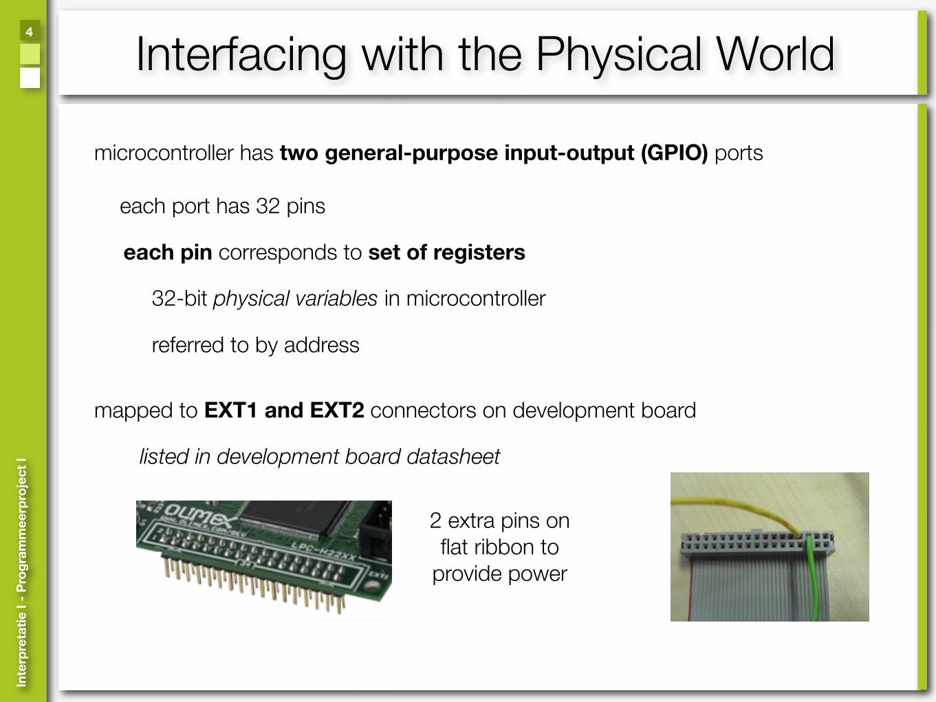
Interfacing with the Physical World4
microcontroller has two general-purpose input-output (GPIO) ports
mapped to EXT1 and EXT2 connectors on development board
each port has 32 pins
2 extra pins on flat ribbon to
provide power
listed in development board datasheet
each pin corresponds to set of registers
32-bit physical variables in microcontroller
referred to by address
Inte
rpre
tati
e I -
Pro
gra
mm
eerp
roje
ct I
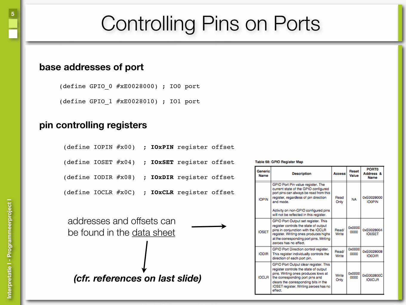
Controlling Pins on Ports5
(define GPIO_0 #xE0028000) ; IO0 port (define GPIO_1 #xE0028010) ; IO1 port
base addresses of port
(define IOPIN #x00) ; IOxPIN register offset
(define IOSET #x04) ; IOxSET register offset
(define IODIR #x08) ; IOxDIR register offset
(define IOCLR #x0C) ; IOxCLR register offset
pin controlling registers
addresses and offsets can be found in the data sheet
(cfr. references on last slide)

Inte
rpre
tati
e I -
Pro
gra
mm
eerp
roje
ct I
Configuring Pin Direction6
(define pin6 (ash 1 6))(write pin6 GPIO_0 IODIR)
Setting P0.06 to outputEverything else is input now!!
Using logical or to set P0.06 respecting previous settings
(define previous-dir (read port IODIR))(write (logior previous-dir (ash 1 6)) GPIO_0 IODIR)
(define (set-dir! port pin) (write (logior (read port IODIR) pin) port IODIR))
Abstracted away into functions
(define (set-dir-input! port pin) (write (logand (read port IODIR)
(lognot pin)) port IODIR))

Inte
rpre
tati
e I -
Pro
gra
mm
eerp
roje
ct I
Producing High Value On Pin7
(write (ash 1 6) gpio0 IOSET)
Setting P0.06 to high = writing 1 << 6
Does not change other pins
(define (set-pin! port pin) (write pin port IOSET))
Abstracted away away into a function
(define (clear-pin! port pin) (write pin port IOCLR))
Setting a pin to low is very similar

Inte
rpre
tati
e I -
Pro
gra
mm
eerp
roje
ct I
Exercise: Blinking LED8
What do we need to do:
1. set target pin direction2. set pin to high3. wait for a while4. set pin to low5. wait for a while6. repeat from 2

Inte
rpre
tati
e I -
Pro
gra
mm
eerp
roje
ct I
Exercise: Blinking LED8
What do we need to do:
1. set target pin direction2. set pin to high3. wait for a while4. set pin to low5. wait for a while6. repeat from 2
(define led-pin (ash 1 6))
(set-dir! GPIO_0 led-pin)

Inte
rpre
tati
e I -
Pro
gra
mm
eerp
roje
ct I
Exercise: Blinking LED8
What do we need to do:
1. set target pin direction2. set pin to high3. wait for a while4. set pin to low5. wait for a while6. repeat from 2
(define led-pin (ash 1 6))
(set-dir! GPIO_0 led-pin)
(set-pin! GPIO_0 led-pin)

Inte
rpre
tati
e I -
Pro
gra
mm
eerp
roje
ct I
Exercise: Blinking LED8
What do we need to do:
1. set target pin direction2. set pin to high3. wait for a while4. set pin to low5. wait for a while6. repeat from 2
(define led-pin (ash 1 6))
(set-dir! GPIO_0 led-pin)
(set-pin! GPIO_0 led-pin)
(clear-pin! GPIO_0 led-pin)

Inte
rpre
tati
e I -
Pro
gra
mm
eerp
roje
ct I
Exercise: Blinking LED8
What do we need to do:
1. set target pin direction2. set pin to high3. wait for a while4. set pin to low5. wait for a while6. repeat from 2
(wait-us 1000000) ; this will wait for that ; many μsecs, one second
(define led-pin (ash 1 6))
(set-dir! GPIO_0 led-pin)
(set-pin! GPIO_0 led-pin)
(clear-pin! GPIO_0 led-pin)

Inte
rpre
tati
e I -
Pro
gra
mm
eerp
roje
ct I
References9
http://www.nxp.com/acrobat_download/usermanuals/UM_LPC2114_2124_2212_2214_2.pdf
Datasheet NXP LPC2214 Microcontroller
Armpit Scheme Interpreter
http://armpit.sourceforge.net/
http://library.thinkquest.org/16497/intro/index.html
Introduction to Electronics
Datasheet Olimex H-2214 Develoment Board
http://machineproject.com/2007/06/02/electronics-for-artists/
http://openbookproject.net//electricCircuits/
http://www.olimex.com/dev/lpc-h2214.html