Embed Size (px)
Citation preview
1
Basic network Concepts
Instructors:
Fu-Chiung Cheng
(鄭福炯 )
Associate Professor
Computer Science & Engineering
Tatung University
2
Contents
Networks Layers TCP/IP Packet format
3
Networks
• Network: a collection of computers and other devices that can send data to and receive data from each other.
• Each machine on a network is called a node
• Nodes that are fully functional computers are also called hosts
• Each network node has an address
4
G
G
G
G
G
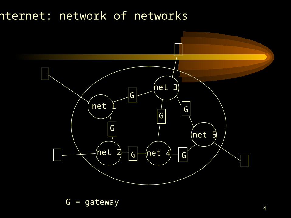
net 1
net 2
net 3
net 4
net 5
G = gateway
G
Internet: network of networks
5
Layers of a Network
• Networking is complex• Networking is divided into several layers• Each layer represents a different level of
abstraction between the physical hardware and the information to be transmitted
• Layering: the grouping of the communication functions into related and manageable sets
• Network architecture: a set of protocols that specify how every layer is to function
6
Layers of a Network
• Benefits of layering: – Simplifying he design process – Leading to flexibility in modifying and developing
the network
• There are several different layer models.– OSI seven-layer model– TCP/IP
• We focus on standard TCP/IP four-layer model.
7
The OSI reference model
• There was pressure in the 1970s for an open systems architecture.
• International Organization for Standardization (ISO) developed a reference model for open system interconnect (OSI) and later to develop associated standard protocols.
• The OSI reference model provided a framework for the overall communications process and was intended to facilitate the development of standards.
8
The OSI reference model
• The OSI model partitions the overall communication process into functions that are carried out by various layers.
• In each layer a process on one machine carries out a conversation with a peer process on the other machine.
• The processes at layer n are referred to as layer n entities.
9
The OSI reference model
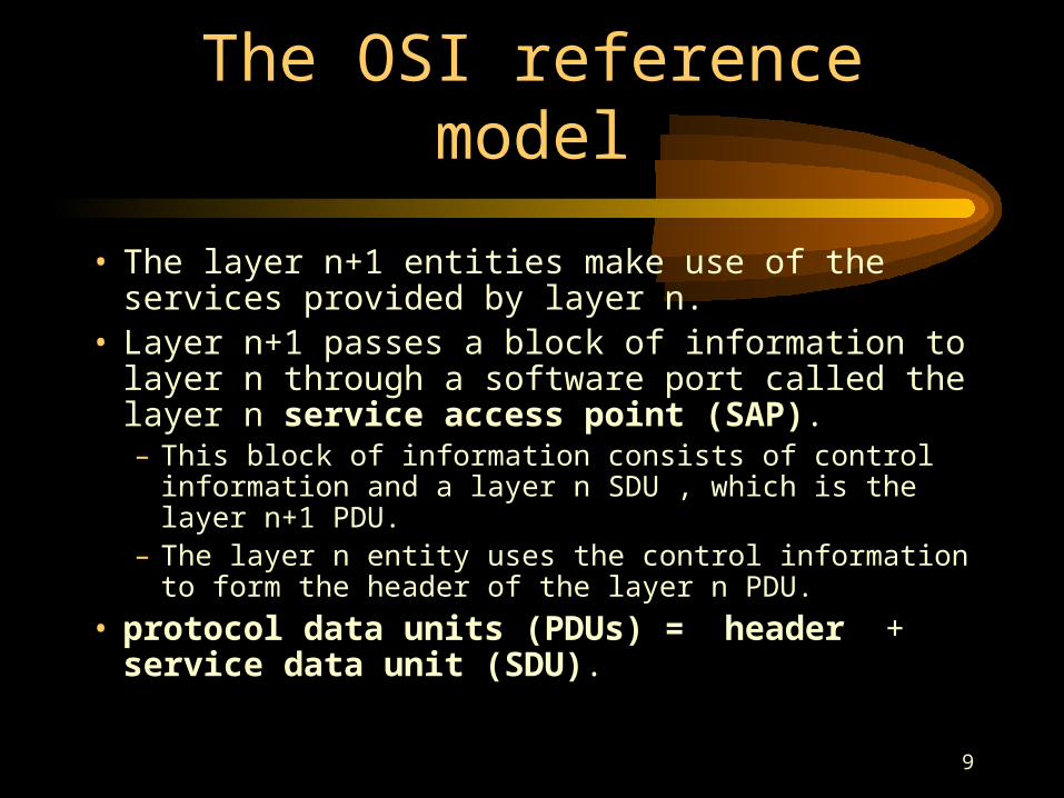
• The layer n+1 entities make use of the services provided by layer n.
• Layer n+1 passes a block of information to layer n through a software port called the layer n service access point (SAP).– This block of information consists of control information
and a layer n SDU , which is the layer n+1 PDU.– The layer n entity uses the control information to form
the header of the layer n PDU.
• protocol data units (PDUs) = header + service data unit (SDU).
10
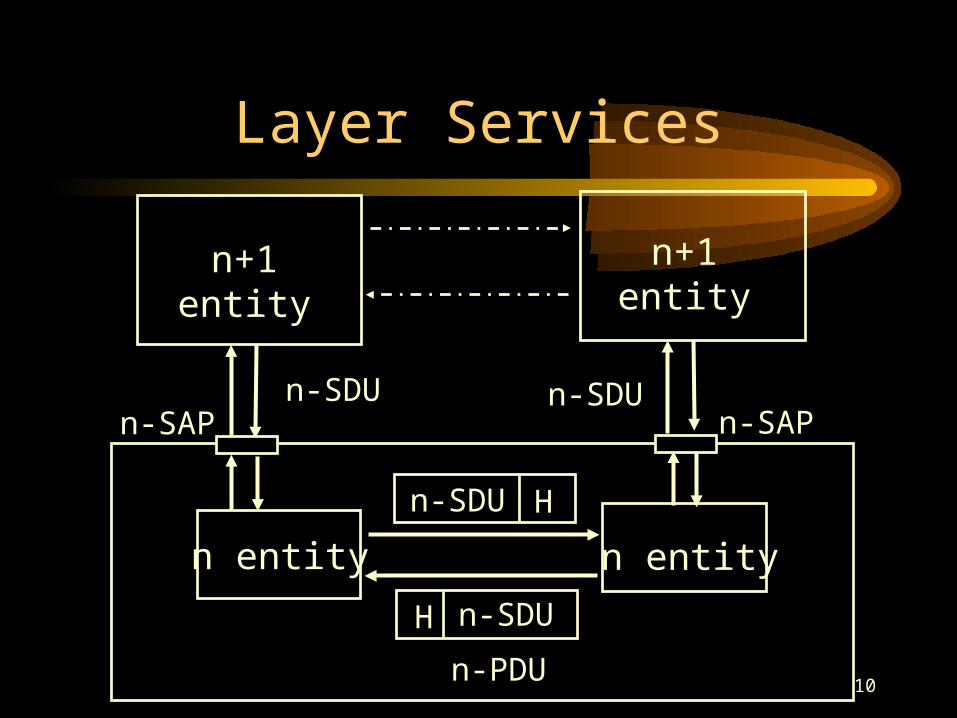
Layer Services
n+1entity
n-SAP
n+1entity
n-SAP
n entity n entity
n-SDU
n-SDU
n-SDU
H
H n-SDU
n-PDU
11
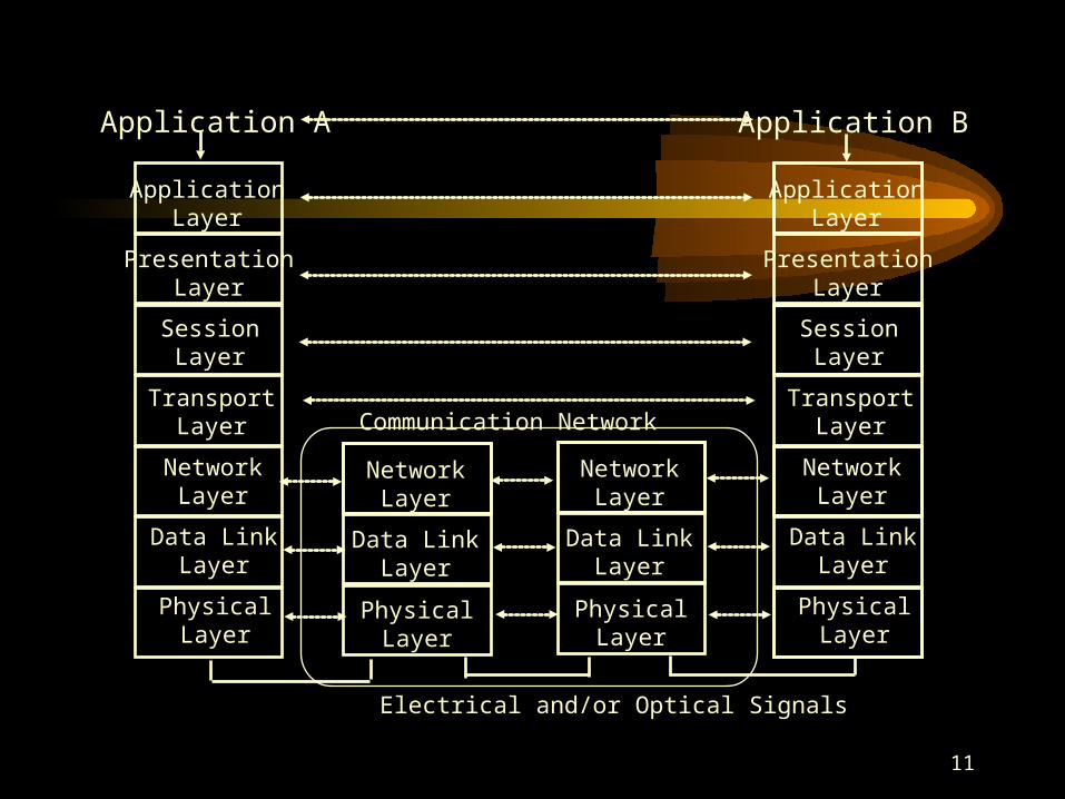
ApplicationLayer
PresentationLayer
SessionLayer
TransportLayer
NetworkLayer
Data LinkLayer
PhysicalLayer
ApplicationLayer
PresentationLayer
SessionLayer
TransportLayer
NetworkLayer
Data LinkLayer
PhysicalLayer
NetworkLayer
Electrical and/or Optical Signals
Application A Application B
Data LinkLayer
PhysicalLayer
NetworkLayer
Data LinkLayer
PhysicalLayer
Communication Network
12
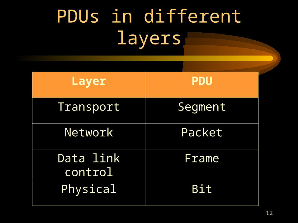
PDUs in different layers
Layer PDU
Transport Segment
Network Packet
Data link control Frame
Physical Bit
13
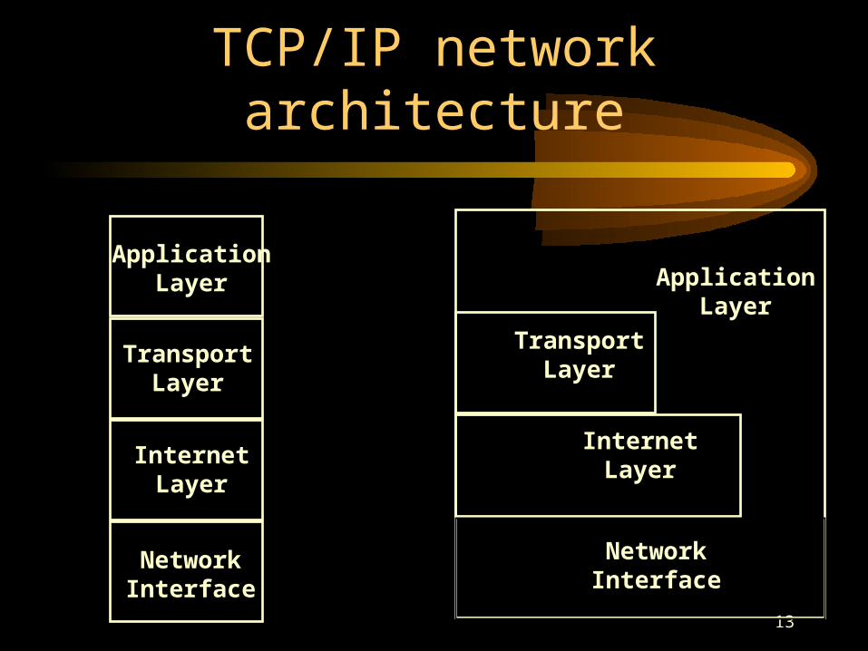
TCP/IP network architecture
ApplicationLayer
TransportLayer
InternetLayer
NetworkInterface
ApplicationLayer
TransportLayer
InternetLayer
NetworkInterface
14
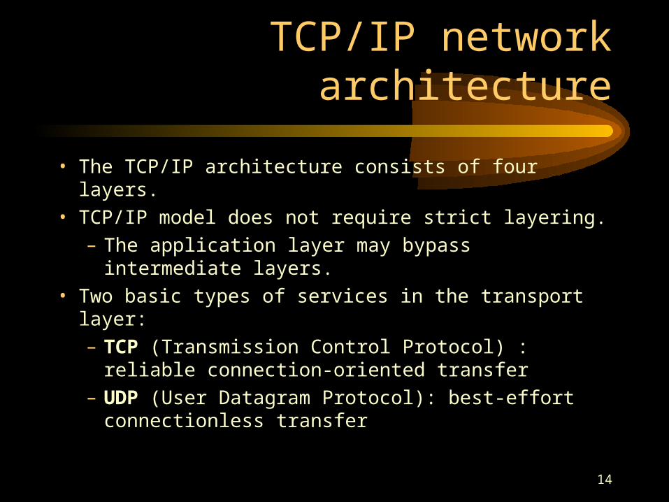
TCP/IP network architecture
• The TCP/IP architecture consists of four layers.• TCP/IP model does not require strict layering.
– The application layer may bypass intermediate layers.
• Two basic types of services in the transport layer:– TCP (Transmission Control Protocol) : reliable
connection-oriented transfer– UDP (User Datagram Protocol): best-effort
connectionless transfer
15
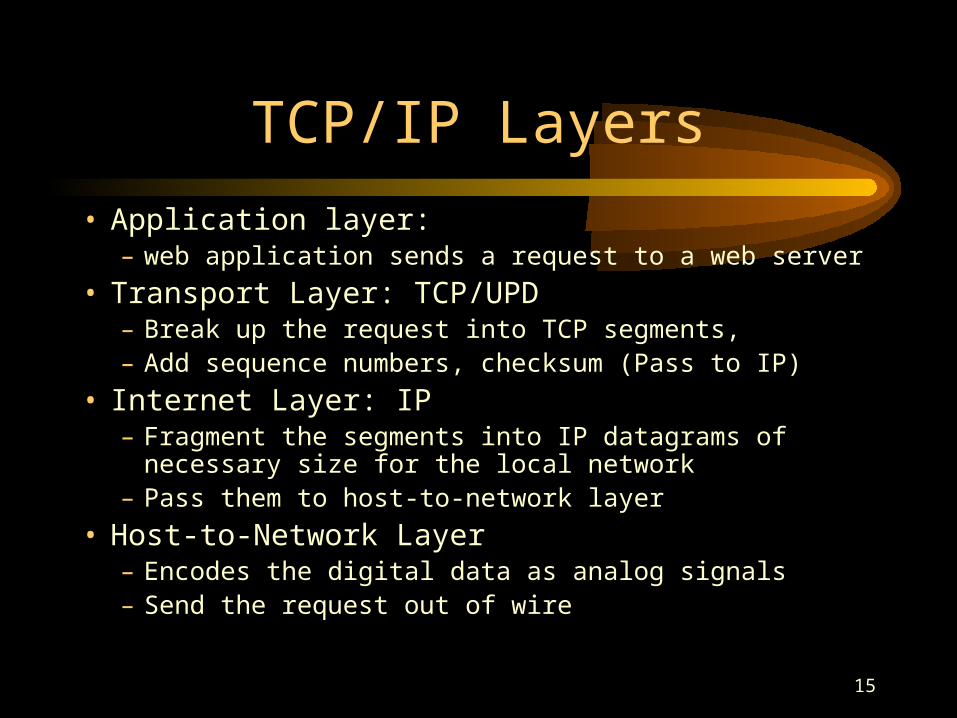
TCP/IP Layers
• Application layer: – web application sends a request to a web server
• Transport Layer: TCP/UPD– Break up the request into TCP segments,– Add sequence numbers, checksum (Pass to IP)
• Internet Layer: IP– Fragment the segments into IP datagrams of necessary size
for the local network– Pass them to host-to-network layer
• Host-to-Network Layer– Encodes the digital data as analog signals – Send the request out of wire
16
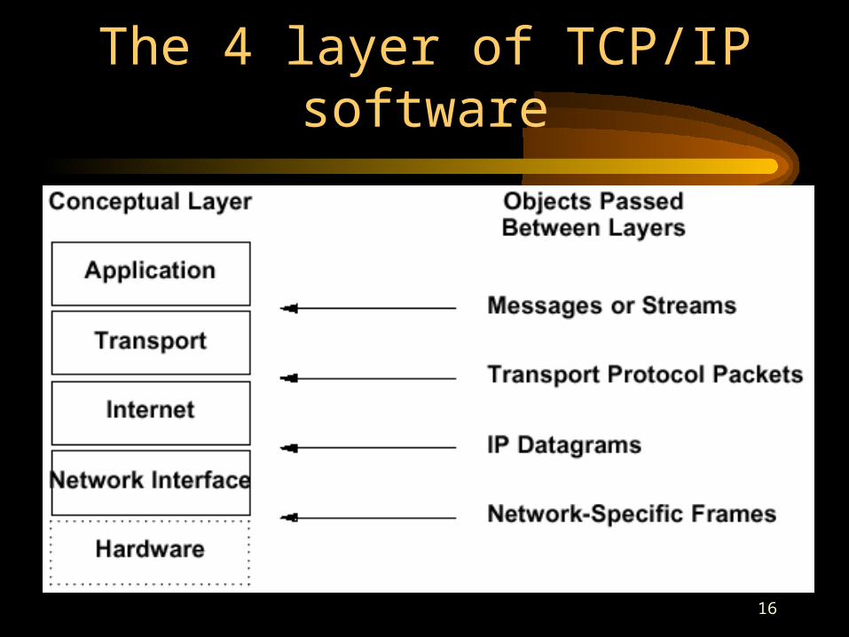
The 4 layer of TCP/IP software
17
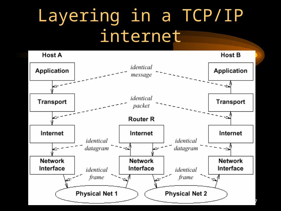
Layering in a TCP/IP internet
18
Application Layer
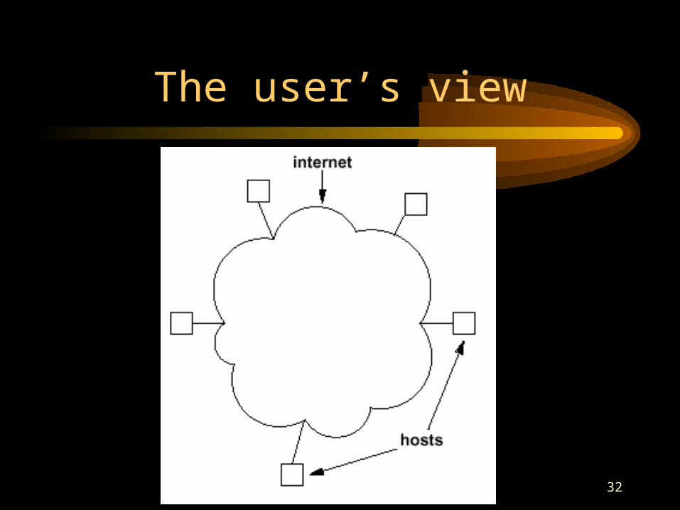
• From the user’s point of view, the Internet appears to consists of a set of application programs that carry out useful communication tasks.
• The most popular Internet application services include:– WWW– E-mail– File transfer– Remote login
19
Transport Layer: TCP/UPD
• There is no guarantee that datagrams will be delivered based on TCP/IP.
• Even datagrams may be delivered, they may have been corrupted in transit.
• Even datagrams arrive uncorrupted, they do not necessarily arrive in the order in which they are sent.
• Transport layer is responsible for ensuring that packets are received in the order they were sent and making sure that no data is lost or corrupted.
20
Transport Layer: TCP/UPD
• There are two primary protocols:– TCP (transmission control protocol)– UDP (User Datagram Protocol)
• TCP (reliable protocol)– High-overhead protocol that allows for transmission of
lost or corrupted data and delivery of bytes in the order they were sent
• UDP (unreliable protocol)– Allows the receiver to detect corrupted packages but
does not guarantee that packets are delivered in the correct order
– Much faster than TCP
21
Internet Layer
• OSI model: network layer• Network layer:
– Define how bits and bytes of data are organized into larger groups called packets
– Define addressing scheme by which different machines can find each other
– Internet protocol (IP protocol) is the most widely used network layer protocol in the world.
– Other protocols: IPX (NetWare), AppleTalk (Mac.), NetBEUI (Windows)
22
Internet Layer
• Datagrams: packets sent across internet• IP datagram:
– header: 20~60 bytes– Data: up to 65515– In practice a few dozen byte to 8K+
• At the network level, an internet provides two broad types of services that all application program use.– Connectionless packet delivery service– Reliable stream transport service
23
Host-to-Network Layer
• Hardware• OSI model (physical & link layers)• Physical layer is alanlog
– Bits and bytes are digital– Digital-to-analog conversion on senders– Analog-to-digital conversion on receivers
• Link layer– Error correction and redundancy– Real analog systems have noise
24
Protocols
• Protocols provide the syntactic and semantic rules for communications.– the details of message formats – how a computer responds when a message arrives – how a computer handles errors or abnormal conditions.
• Protocols are to communication what algorithms are to computation.
• Protocols allows one to understand data communication without depending on detailed knowledge of a particular vendor’s network hardware.
25
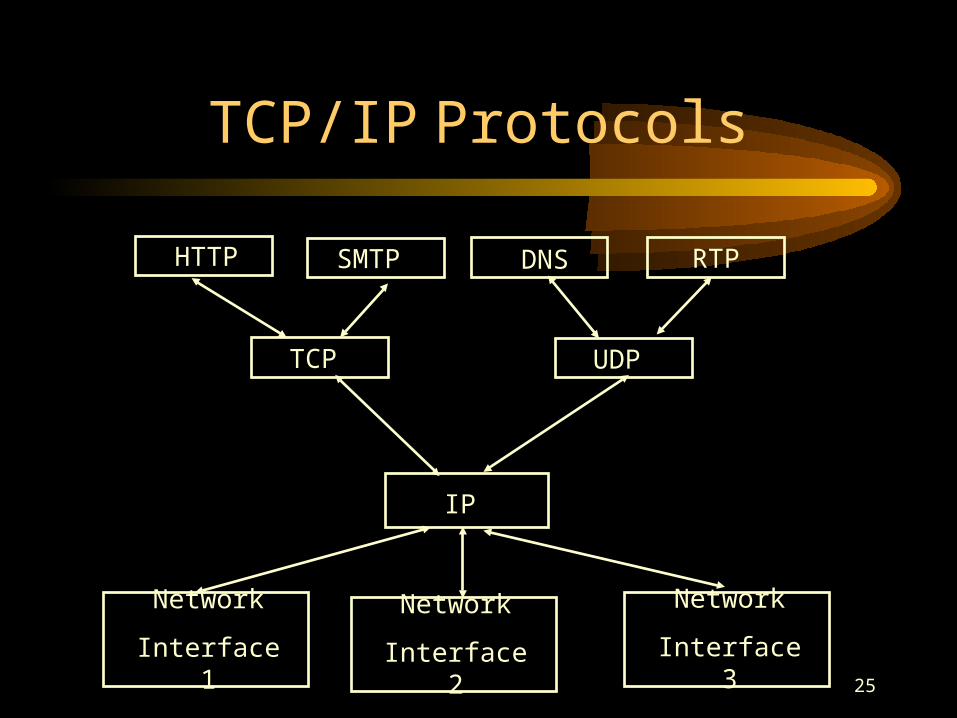
TCP/IP Protocols
HTTP SMTP RTP
TCP UDP
IP
Network
Interface 1
Network
Interface 3
Network
Interface 2
DNS
26
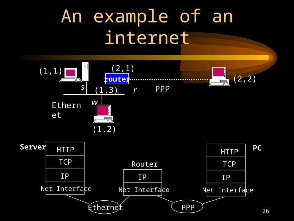
An example of an internet
(1,1)
Net Interface
IP
TCP
HTTP
Net Interface
IP
Net Interface
IP
TCP
HTTP
Ethernet PPP
Router
routers
(1,2)
w
(2,1)
(1,3) r(2,2)
PPP
Ethernet
Server PC
27
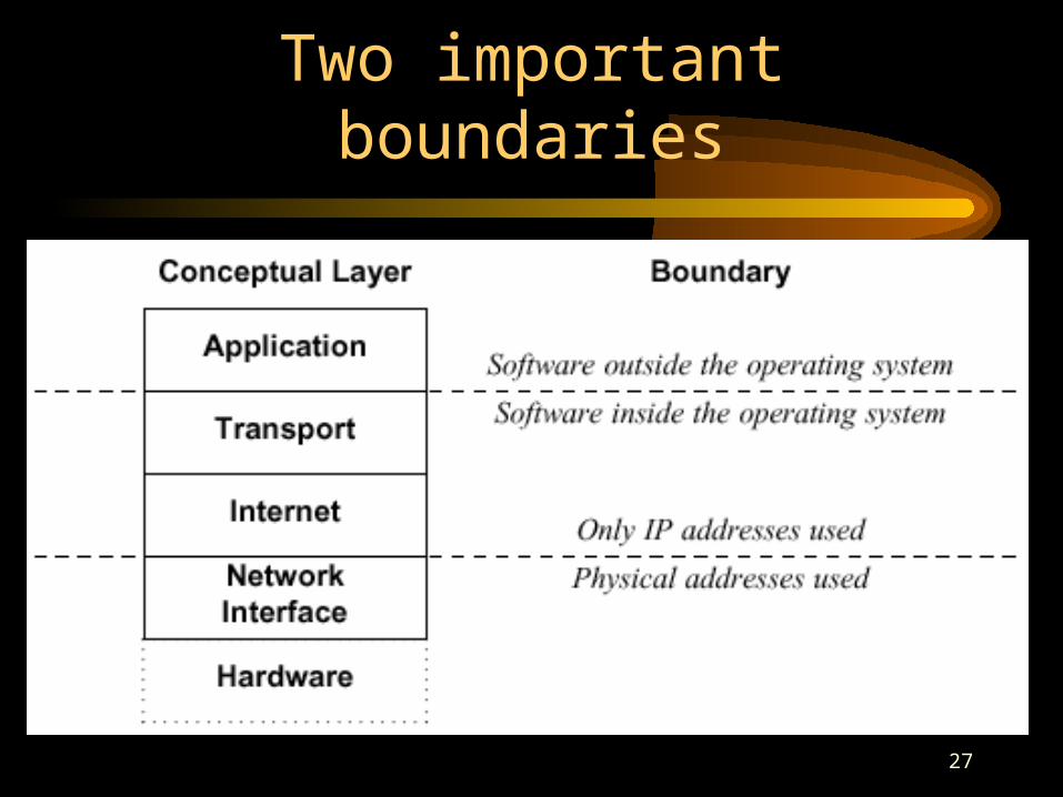
Two important boundaries
28
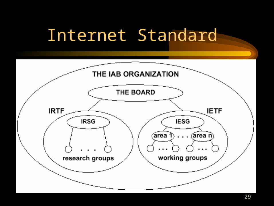
Internet Standard
• The IETF (Internet Engineering Task Force) concentrate on short-term or medium-term engineering problems.
• The IRTF (Internet Research Task Force) coordinates research activities related to TCP/IP protocols or internet architecture in general.
• IETF RFCs (Request for Comments) – page 42~45
• Other group: W3C (http, HTML, XML)
29
Internet Standard
30
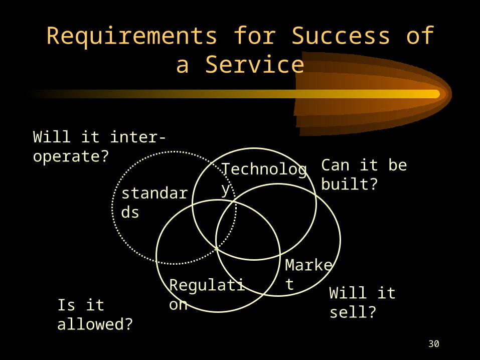
Requirements for Success of a Service
standards
Regulation
Technology
Market
Will it inter-operate? Can it be
built?
Is it allowed?
Will it sell?
31
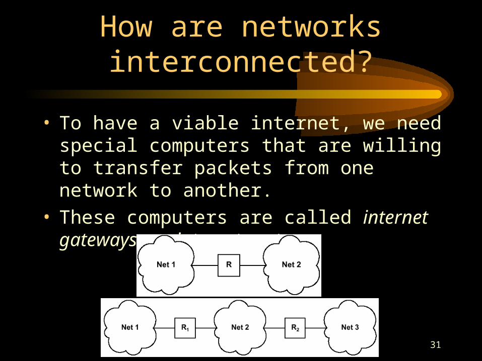
How are networks interconnected?
• To have a viable internet, we need special computers that are willing to transfer packets from one network to another.
• These computers are called internet gateways or internet routers.
32
The user’s view
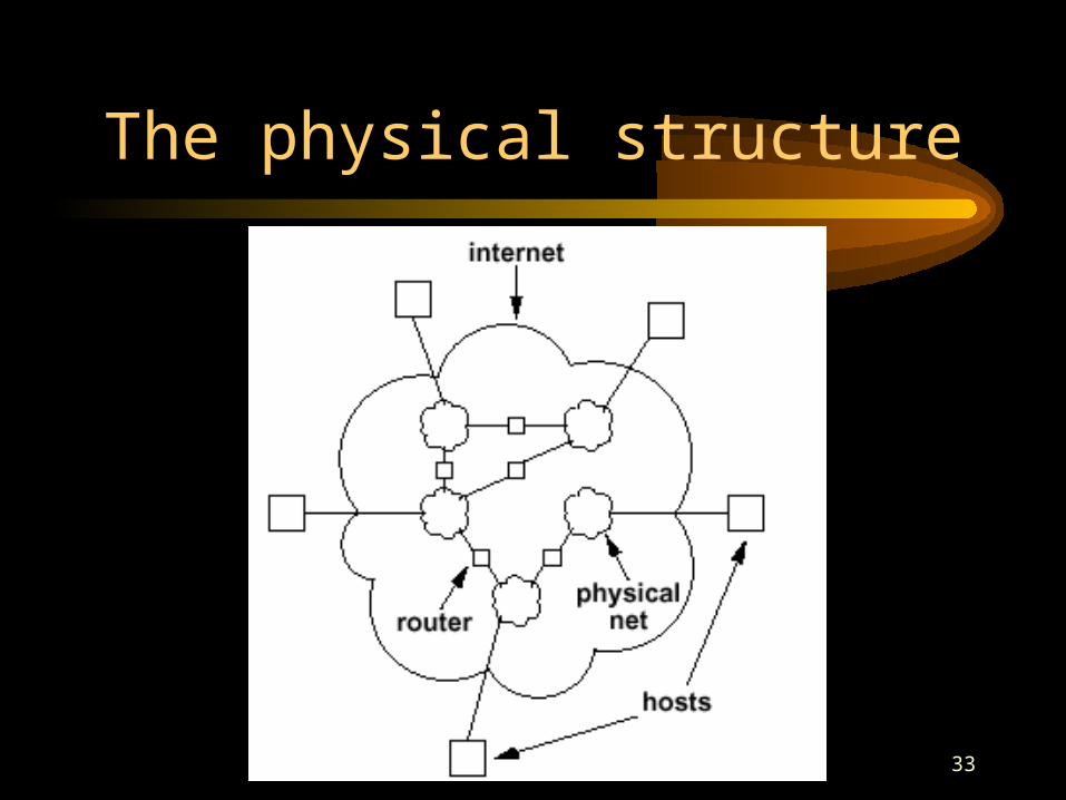
33
The physical structure
34
IP address
• To provide universal communication service, it needs a globally accepted method of identifying each computer that attached to it.
• Host identifiers are classified as– names: what an object is– addresses: where it is– routes: how rot get there
• Compact, binary addresses are chosen as the TCP/IP universal host identifiers.
• This make computations such as the selection of a route efficient.
35
IP address
• Each host on a TCP/IP internet is assigned a unique 32-bit internet address that is used in all communication with that host.
• Each address is a pair (netid, hostid).– netid identifies a network– hostid identifies a host on that network
• IP addresses do not specify an individual computer, but a connection to a network.
36
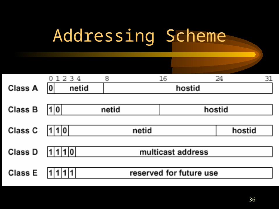
Addressing Scheme
37
IP address
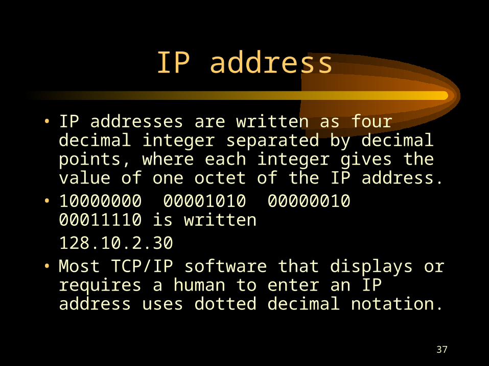
• IP addresses are written as four decimal integer separated by decimal points, where each integer gives the value of one octet of the IP address.
• 10000000 00001010 00000010 00011110 is written128.10.2.30
• Most TCP/IP software that displays or requires a human to enter an IP address uses dotted decimal notation.
38
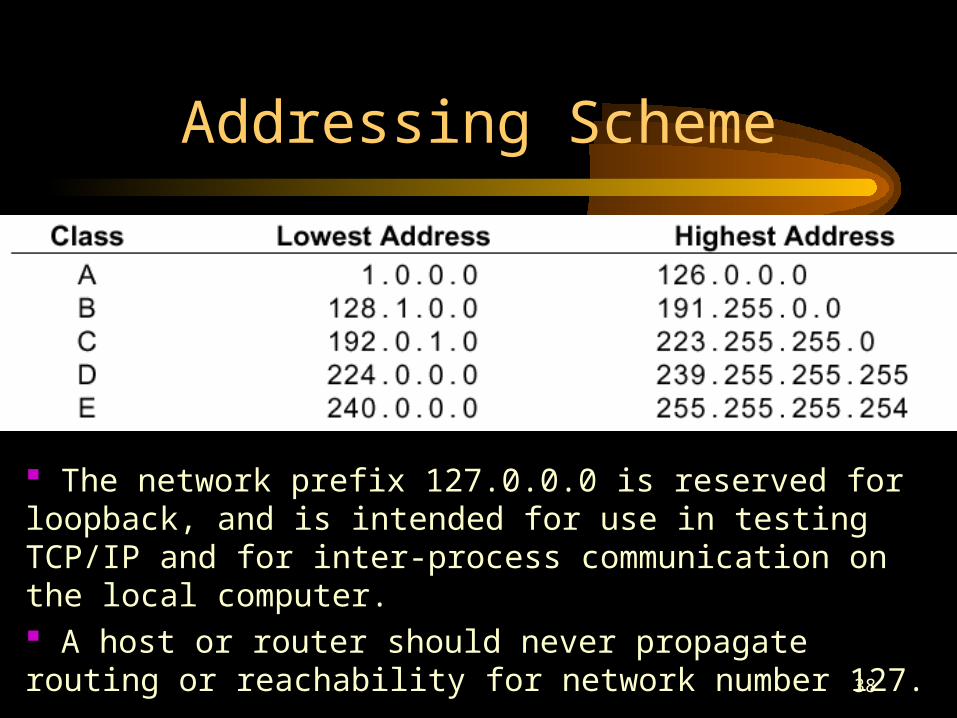
Addressing Scheme
The network prefix 127.0.0.0 is reserved for loopback, and is intended for use in testing TCP/IP and for inter-process communication on the local computer. A host or router should never propagate routing or reachability for network number 127.
39
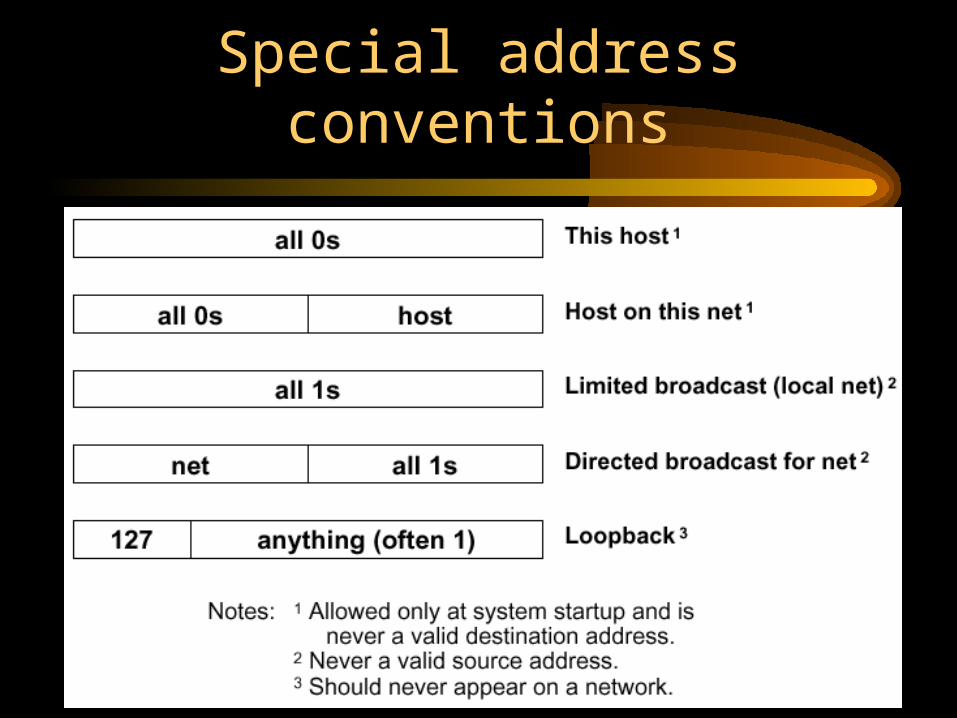
Special address conventions
40
Internet addressing authority
• Originally, the Internet Assigned Number Authority (IANA) had control over numbers assigned, and set the policy.
• In late 1998, the Internet Corporation For Assigned Names and Numbers (ICANN) sets policy and assigns values for name and other constants used in protocols as well as address.
41
Internet addressing authority
• Only the largest ISPs need to contact ICANN.
• Once an organization obtains a prefix for a network, the organization can choose how to assign a unique suffix to each host on the network without contacting the central authority.
42
Network byte order
• The internet standard specifies that integers are sent with the most significant byte first (i.e., big endian).
• Computers using Intel microprocessors are based on little-endian system.
43
Connectionless delivery system
• The packet delivery service is an unreliable, best-effort, connectionless service.
• The protocol that defines the unreliable, connectionless delivery mechanism is called the Internet Protocol, or IP.
44
Connectionless delivery system
• Unreliable– Delivery is not guaranteed.– The packet may be lost, duplicated, delayed, or
delivered out of order.
• Best-effort– The internet software makes an earnest attempt to
deliver packets.– Unreliability arises only when resources are exhausted
or underlying networks fail.
• Connectionless– Each packet is treated independently from all others.
45
IP Protocol
• IP provides three definitions:– IP specifies the exact format of all data as
it passes across the internet.– IP software performs the routing function.– IP includes a set of rules that embody the
idea of unreliable packet delivery.
• A TCP/IP internet is sometimes called an IP-based technology.
46
Internet Datagram
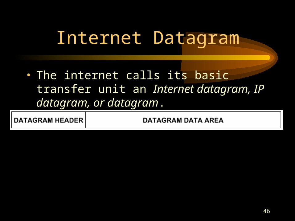
• The internet calls its basic transfer unit an Internet datagram, IP datagram, or datagram.
47
Internet Datagram
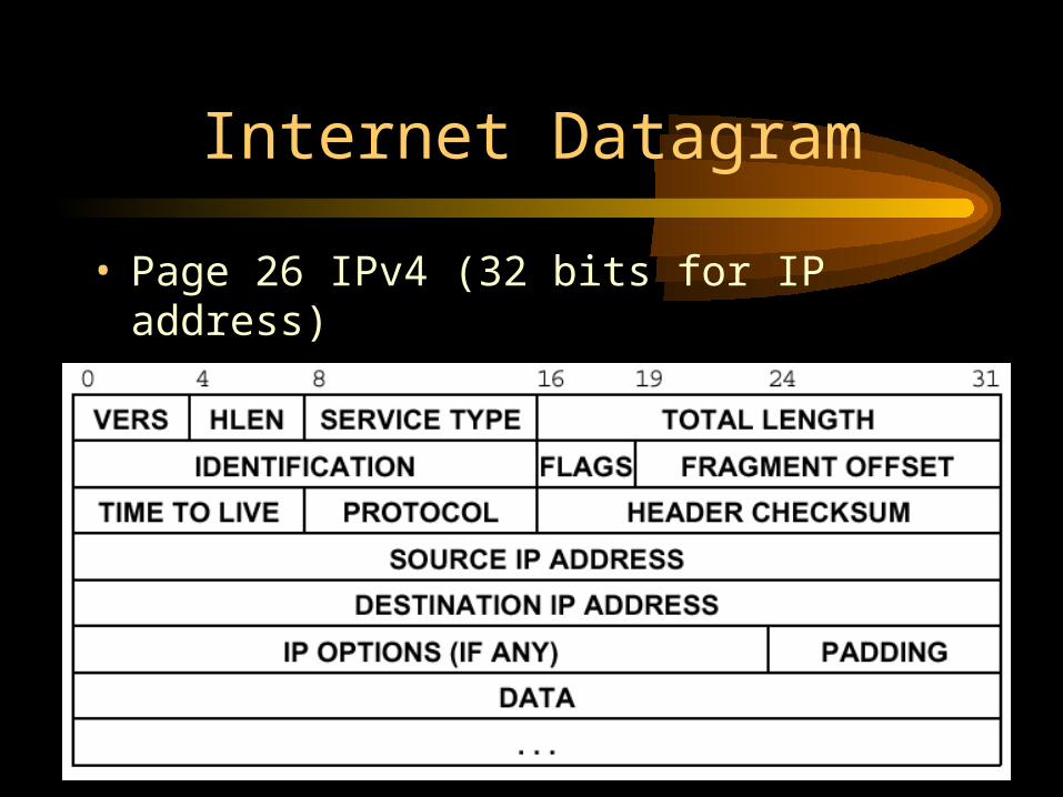
• Page 26 IPv4 (32 bits for IP address)• IPv6 128 bits for IP address
48
Protocol version
• All IP software is required to check the 4-bit version field before processing a datagram to ensure it matches the format the software expects.
• If standards change, machines will reject datagrams with protocol versions that differ from theirs.
• The current IP protocol version is 4.• IPv4 is often used to denote the current
protocol.
49
Header length
• The 4-bit header length field gives the datagram header length measured in 32-bit words.
• All fields in the header have fixed length except for IP OPIONS and corresponding PADDING fields.
• The most common header, which contains no options and no padding, measures 20 octets and has a header length field equal to 5.
50
Total length
• The TOTAL LENGTH field gives the length of IP datagram, including header and data.
• The size of data area can be computed by subtracting the length of the header from the TOTAL LENGTH.
• Because the TOTAL LENGTH field is 16 bits long, the maximum possible size of an IP datagram is 216 or 65,535 octets.
• This may become more important in the future if higher speed networks can carry data packets larger than 65,535 octets.
51
Datagram type of service
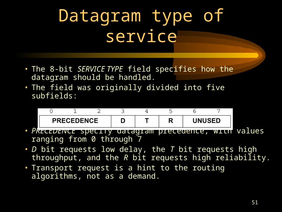
• The 8-bit SERVICE TYPE field specifies how the datagram should be handled.
• The field was originally divided into five subfields:
• PRECEDENCE specify datagram precedence, with values ranging from 0 through 7
• D bit requests low delay, the T bit requests high throughput, and the R bit requests high reliability.
• Transport request is a hint to the routing algorithms, not as a demand.
52
Fragmentation control
53
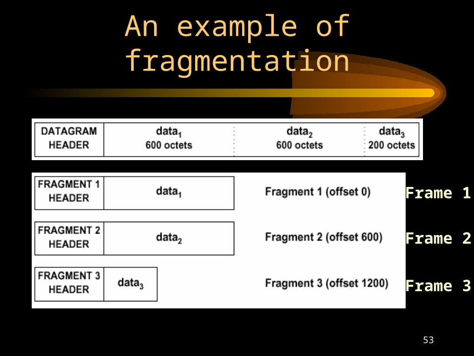
An example of fragmentation
Frame 1
Frame 2
Frame 3
54
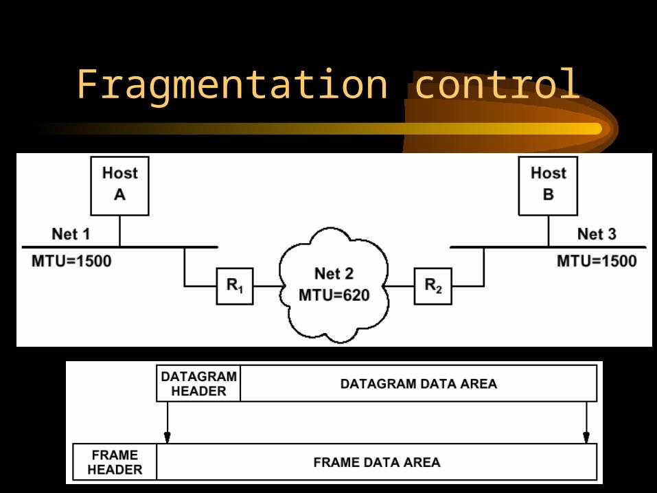
Fragmentation control
• Three fields in the datagram header control fragmentation and reassembly of datagrams.– IDENTIFCATION
• Computers sending IP datagrams must generate a unique value for the IDENTIFCATION field for each datagram.
55
Fragmentation control
– FLAGS• Setting the do not fragment bit to 1 specifies
that the datagram should not be fragmented.• The more fragment bit specifies whether the
fragment contains data from the middle of the original datagram or from the end.
– We need this bit because the TOTAL LENGTH field refers to the size of the fragment.
– FRAGMENT OFFSET• This field specifies the offset in the original
datagram of the data being carried in the fragment, measured in units of 8 octets, starting at offset zero.
56
Time to Live
• Routers and hosts must decrement the TIME TO LIVE field by one and remove the datagram from the internet when its time expires.
• In practice, the TTL acts a “hop limit” rather than an estimate of delays.
• Two uses:– It guarantees that datagrams cannot travel around
an internet forever.– Source might want to intentionally limit the journey of
the packet.
57
Other datagram header fields
• Field PROTOCOL specifies which high-level protocol was used to create the message carried in the DATA area of the datagram.
• Field HEADER CHECKSUM ensures integrity of header values.
• Field SOURCE IP ADDRESS and DESTINATION IP ADDRESS contains the 32-bit IP addresses.
• Field PADDING contains zeros that may be needed to ensure the datagram header extends to an exact multiple of 32 bits.
58
IP checksum
• This is formed by treating the header as a sequence of 16-bit integers, adding them together using one’s complement arithmetic, an then taking the one’s complement of the result.
59
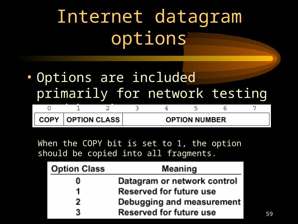
Internet datagram options
• Options are included primarily for network testing or debugging.
When the COPY bit is set to 1, the option should be copied into all fragments.