Embed Size (px)
Citation preview
8/3/2019 10.1.1.14.8516(2)
http://slidepdf.com/reader/full/10111485162 1/7
Smart Transducers - Principles, Communications, and Configuration
Wilfried Elmenreich Stefan Pitzek
Institut f ur Technische Informatik Institut f ur Technische Informatik
Technische Universitat Wien Technische Universitat WienKarlsplatz 13, Vienna, Austria Karlsplatz 13, Vienna, Austria
[email protected] [email protected]
Abstract — Transducers are sensors and actuators
in order that a computer system can interact with the
physical environment. An intelligent or smart trans-
ducer is the integration of an analog or digital sensor
or actuator element, a processing unit, and a communi-
cation interface. In this paper we describe the basic de-
sign principles for smart transducers and compare two
smart transducer interface standards, the IEEE 1451.2STI and the OMG STI, with respect to general design
decisions and the management of configuration infor-
mation in particular. The IEEE 1451.2 standard favors
the introduction of self-contained nodes, which keep the
configuration data physically associated to the nodes. In
contrast, the OMG STI standard follows the approach
of keeping memory requirements on nodes very low and
instead enforces a tight integration of smart transducer
systems with software tools and external system descrip-
tions in a general configuration framework.
1 Introduction
Transducers are sensors and actuators in order that a com-
puter system can interact with the physical environment. In
1982, Ko and Fung introduced the term “intelligent trans-
ducer” [1]. An intelligent or smart transducer is the inte-
gration of an analog or digital sensor or actuator element,
a processing unit, and a communication interface. In case
of a sensor, the smart transducer transforms the raw sen-
sor signal to a standardized digital representation, checks
and calibrates the signal, and transmits this digital signal to
its users via a standardized communication protocol [2]. In
case of an actuator, the smart transducer accepts standard-ized commands and transforms these into control signals for
the actuator. In many cases, the smart transducer is able to
locally verify the control action and provide a feedback at
the transducer interface. With the advent of modern micro-
controllers it became possible to built low-cost smart trans-
ducers by using commercial-off-the-shelf microcontrollers
that provide a standard communication interface, such as
a UART (Universal Asynchronous Receiver/Transmitter).
Thus, the usage of smart transducers can become a cost-
decreasing factor for building embedded control systems.
The objective of this paper is to give a brief overview
on principles, communications, and configuration aspects
for smart transducers. The remainder of the paper is struc-
tured as follows. Section 2 discusses the basic principles of
smart transducers. Section 3 gives an overview on existingcommunication interfaces for smart transducers. Section 4
describes various approaches for configuration support of
smart transducer networks. The paper is concluded in sec-
tion 5
2 Smart Transducer Principles
This section gives an introduction to the basic principles
that are used for the design of smart transducer systems.
Note that a particular smart transducer system will not nec-
essarily implement the whole set of the presented ideas.
2.1 Two-Level Design Approach
The smart transducer technology introduces a two-level de-
sign approach [3] that helps to reduce the overall complex-
ity of a system by separating transducer-specific implemen-
tation issues from interaction issues between different smart
transducers.
The transducer manufacturer will deal with instrument-
ing the local transducer and signal conditioning in order
to export the transducer’s service in a standardized way.
Transducer manufacturers are thus liberated from interoper-ability issues between sensors, naming inconsistencies and
the network topology of the total system.
The user of a smart transducer’s service can access its
data via an abstract interface that hides the internal com-
plexity of the transducer hardware and software. Thus,
smart transducer applications can be built in a less complex
way.
8/3/2019 10.1.1.14.8516(2)
http://slidepdf.com/reader/full/10111485162 2/7
2.2 Interface Design
The most critical factor for a smart transducer design is the
construction of the interfaces to smart transducers. We dis-
tinguish the smart transducer interface and the transducer
communication interface.
The smart transducer interface is an abstract interface
that gives access to the transducer features, such as mea-surement value or set value, respectively, but also ven-
dor ID numbers, diagnostic information and setup parame-
ters. Usually, a smart transducer interface provides different
types of service, such as configuration, remote diagnosis,
and real-time measurement. In order to keep a clean sepa-
ration of functionalities and achieve a better understandabil-
ity of a smart transducer interface, Kopetz proposes the in-
troduction of distinct interfaces for functional different ser-
vices [4]. In detail the following three interface types can
be distinguished:
Real-Time Service (RS) interface: This interface pro-
vides the timely real-time services to the smarttransducer during the operation of the system.
Diagnostic and Management (DM) interface: This
interface opens a communication channel to the inter-
nals of a smart transducer. It is used to set parameters
and to retrieve information about the internals of a
component, e. g., for the purpose of fault diagnosis.
The DM interface is available during system operation
without disturbing the real-time service. Normally,
the DM interface is not time-critical.
Configuration and Planning (CP) interface: This inter-
face is necessary to access configuration properties
of a node. During the integration phase this inter-face is used to generate the “glue” between the au-
tonomous smart transducers. The CP interface is not
time-critical.
The transducer communication interface defines the com-
munication among the transducers in the network. The idea
to connect multiple transducers to a single communication
bus has its roots in the industrial fieldbus networks that date
back to the early 1970s [5]. An early example for a trans-
ducer communication interface is the 4-20 mA current loop,
an analog signal standard for the point-to-point connection
of analogue devices. The transducer communication inter-
face handles aspects such as the communication baud rate,data encoding, flow control, and message scheduling.
The difference between these two interfaces becomes
clear, when they are aligned to the 7-layer of the Interna-
tional Standard Organizations Open System Interconnect
(ISO/OSI) model [6]. While the issues on the smart trans-
ducer interface relate to the application layer (layer 7) of the
OSI reference model, the network communication relates to
the layers below 7, especially the physical layer (layer 1)
and the data link layer (layer 2). The intermediate layers
3-6 are usually not defined for fieldbus systems.
All interfaces have to be well-defined in the value and in
the time domain in order to enable desirable properties such
as interoperability, i. e., the ability of two or more devices,
independent of the manufacturer, to work together in one or
more distributed applications [7], and composability, i. e., if each subsystem implements well-defined interfaces in the
temporal and value domain, it can be guaranteed a priori
that the subsystem provides its specified service also in the
composite system.
2.3 Configuration Support
Dealing with the large number of transducers in many sys-
tems requires a generic approach for configuration and
maintenance. A smart transducer system should thus pro-
vide an automatic or at least semi-automatic configuration.
This requirement for a plug-and-play-like configuration can
be justified by three arguments: First, an automated config-
uration saves time and therefore leads to better maintain-
ability and lower costs. Second, the required qualification
of the person who sets up the system is lower when the
overall system is easier to configure. Third, the number
of configuration faults will decrease, since monotone and
error-prone tasks like looking up configuration parameters
in heavy manuals can be replaced with respective opera-
tions done by a computer. A fully automatic configuration
will in most cases only be possible if the functionality of
the system is reduced to a manageable subset. For more
complex applications consulting a human mind is unavoid-
able. Thus, we distinguish two cases, the automatic set-upof simple subsystems and the computer-supported configu-
ration of large distributed systems.
3 Communication in Smart Trans-
ducer Networks
The design of the network interface for smart transducers
is of great importance. Transducers come in a great variety
with different capabilities from different vendors. Thus, a
smart transducer interface must be very generic to support
all present and future types of transducers. However, it must
also provide standard functionalities to transmit data in atemporally deterministic manner, support a standard data
format, encompass means for fault tolerance, and provide
means for smooth integration into a transducer network and
its application.
A smart transducer interface should conform to a world-
wide standard. Such a standard for a real-time communica-
tion network has been sought for a long time, but efforts to
8/3/2019 10.1.1.14.8516(2)
http://slidepdf.com/reader/full/10111485162 3/7
find a single agreed standard have been hampered by ven-
dors, which were reluctant to support such a single com-
mon standard in fear of losing some of their competitive
advantages [8]. Hence, several different fieldbus solutions
have been developed and promoted. Some of these existing
solutions have been combined and standardized. In 1994,
the two large fieldbus groups ISP (Interoperable Systems
Project supported by Fisher-Rosemount, Siemens, Yoko-gawa, and others) and the WorldFIP (Flux Information Pro-
cessus or Factory Instrumentation Protocol, supported by
Honeywell, Bailey, and others) joined to form the Fieldbus
Foundation (FF). It is the stated objective of the FF to de-
velop a single interoperable fieldbus standard in cooperation
with the International Electrotechnical Commission (IEC)
and the Instrumentation Society of America (ISA).
The IEC worked out the IEC 61158 standard. It is based
on the following existing fieldbus systems [9]:
Foundation Fieldbus: A functional superset of WorldFIP.
The IEC 61158 standard defines also a Foundation
Fieldbus High Speed Ethernet type.
ControlNet: ControlNet has been primarily designed to
meet the requirements of high speed real-time appli-
cations for automation and control. ControlNet fea-
tures the Control and Information Protocol that pro-
vides real-time and peer-to-peer messaging.
Ethernet/IP: EtherNet/IP is an open network based on the
IEEE 802.3 Physical and Data Link standard, the Eth-
ernet TCP/IP protocol suite and the Control and Infor-
mation Protocol.
Profibus: Profibus is a distributed control system for pro-cess automation. Profibus is one of the most popu-
lar fieldbus protocols in this area. In 2001 it claimed
53.6% of the revenue created in the fieldbus sector in
Europe [10].
SwiftNet: SwiftNet is a high performance fieldbus that was
created as a synchronous, high speed flight data bus for
Boeing Commercial Airplane. SwiftNet provides high
data efficiency and clock synchronization among the
communicating nodes.
WorldFIP: WorldFIP is designed with a strictly real-time
capable control scheme based on a producer-consumer
communication model. WorldFIP was published as a
French standard in the late 80s. No significant change
has taken place since the first French standard.
Interbus: Interbus is a digital, serial communication sys-
tem for communication between control systems and
transducer devices. Interbus is optimized, but not lim-
ited to factory automation applications.
P-NET: The P-NET Fieldbus has been used for many
years, and has more than 5000 applications in the pro-
cess industry environment and in discrete parts manu-
facturing plants. P-NET supports also configuration of
transducers by downloading of programs.
The IEC 61158 has the great disadvantage that it still
keeps a diversity of eight different solutions. The ISA,which developed the SP50 standard, and IEC committees
jointly met to make the development of an international
standard possible. ISA SP50 was the same committee that
introduced the 4-20 mA standard back in the 1970s. Mean-
while, other standards for smart transducers were devel-
oped. The IEEE 1451.2 standard [11] deals with the spec-
ification of interfaces for smart transducers. An idea pro-
posed by this standard is the specification of electronic data
sheets to describe the hardware interface and communica-
tion protocols of the smart transducer interface model in a
machine-readable format [12].
In December 2000 the Object Management Group
(OMG) issued a request for proposal (RFP) [13] of a smart transducer interface (STI) in order to form a world-wide
standard that satisfies the following needs: (i) real-time
characteristics and functionalities for the smart transducer
network (ii) online diagnostic service capability (iii) sup-
port for start-up and dynamic configuration (iv) a uniform
naming and addressing scheme for all relevant data in the
smart transducer system (v) a generic interface that en-
ables the smart transducer system to interact with other
systems via a CORBA (Common Object Request Broker
Architecture) gateway, and (vi) the support of communi-
cation interfaces available on current low-cost microcon-
trollers, e. g., UART ports. In response to this RFP, the
time-triggered communication protocol TTP/A extended bya well-defined interface to a CORBA environment has been
submitted jointly by three companies with support of the
Vienna University of Technology. The interface to the
smart transducers uses the concept of an interface file sys-
tem (IFS) that maps all relevant transducer data to a com-
mon address scheme. This IFS allows different application-
specific views of a system, namely a real-time service view,
a diagnostic and management view, and a configuration and
planning view. The interface concept encompasses a com-
munication model that allows accessing the IFS data via a
uniform addressing scheme from the CORBA gateway ob-
ject and provides real-time time-triggered communication
among the smart transducers. This proposed STI standard
has been adopted by the OMG in 2002 [14].
4 Computer-Aided Configuration
To ease the management of fieldbus systems, all major pro-
tocols provide mechanisms, formalisms, and tools that sup-
8/3/2019 10.1.1.14.8516(2)
http://slidepdf.com/reader/full/10111485162 4/7
port this process.
The Foundation Fieldbus [15] provides predefined func-
tion blocks for creating applications and a uniform access
model for nodes with virtual field devices. Field devices
are modelled by a formal description using the device de-
scription language (DDL).
Another fieldbus with an extensive support framework
is LONworks [16], which provides a uniform applica-tion model with predefined data types for communicated
data. LONworks uses standardized functional profiles for
the functional description of field devices. The system is
mainly used for home automation and process control appli-
cations with a strong focus on multi-vendor interoperability
(within LON networks).
The configuration and management framework of the
LIN bus [17] has been specifically tailored for its intended
applications in low-cost car body instrumentation. It en-
forces a tight integration with software tools by defining the
interfaces between the bus and support software and incurs
only a very low overhead on the nodes.
Most of these approaches were developed independently
of each other and specifically tailored for the respective
fieldbus system and its technical attributes. Most notable
exceptions are CAN Kingdom [18], OSEK [19], and IEEE
1451 in their target of being in principle independent of the
underlying physical fieldbus.
4.1 IEEE 1451 Smart Transducer
IEEE 1451 is a family of standards (and proposed stan-
dards) for connecting smart transducers to networks. The
first standard to be published was IEEE 1451.2, which was
approved in September 1997 [20]. IEEE 1451.2 specifiesan electronic data sheet and a digital interface to access
that data sheet, read sensors, and set actuators. IEEE 1451
is not another fieldbus network and covers mainly smart
transducer interface issues. In its current form, IEEE 1451
is divided into four sub-standards as described in the fol-
lowing. IEEE 1451.1 defines a network independent com-
mon object model for networked smart transducers [21].
IEEE 1451.2 defines a digital interface and communica-
tion protocol for the connection of transducers and a mi-
crocontroller. Furthermore, IEEE 1451.2 defines transducer
electronic data sheet (TEDS) that describe the smart trans-
ducer properties in a machine-readable format. The other
two parts of the standard, IEEE P1451.3 and IEEE P1451.4are not yet ratified. IEEE P1451.3 specifies properties for
distributed multi-drop systems in hazardous environments,
while IEEE P1451.4 covers a mixed-mode service of analog
and digital transducers, whereas analog transducers shall be
enhanced with self-identification and configuration capabil-
ities [22].
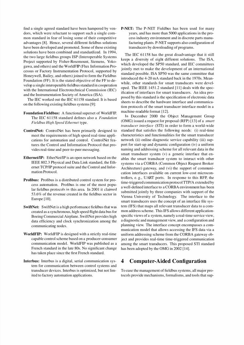
Figure 1 depicts a sample IEEE 1451 network with three
Actuator
NCAP
Network
TIIControl/Monitoring Device
Address
Logic
Sensor
NCAP
Address
Logic
NCAP
STIM STIM
TII TII
Address
Logic
STIMSensorActuator
Fig. 1: Example IEEE 1451 network
STIMs (Smart Transducer Interface Modules). The first
STIM contains a sensor, the second one an actuator and
the third one contains both, e. g., for a distributed control
application (actuating based on local measurements). The
STIMs are interfaced by a 10-wire connection that is stan-
dardized in IEEE 1451.2 as Transducer Independent Inter-
face (TII). IEEE 1451.1 specifies an information model forNetwork Capable Application Processors (NCAPs). The
NCAP may contain application software that can access the
transducer(s) through a set of standardized functions. The
architecture lines out clearly the two-level design approach
as described in Section 2.
4.2 OMG Smart Transducers Interface Stan-
dard Descriptions
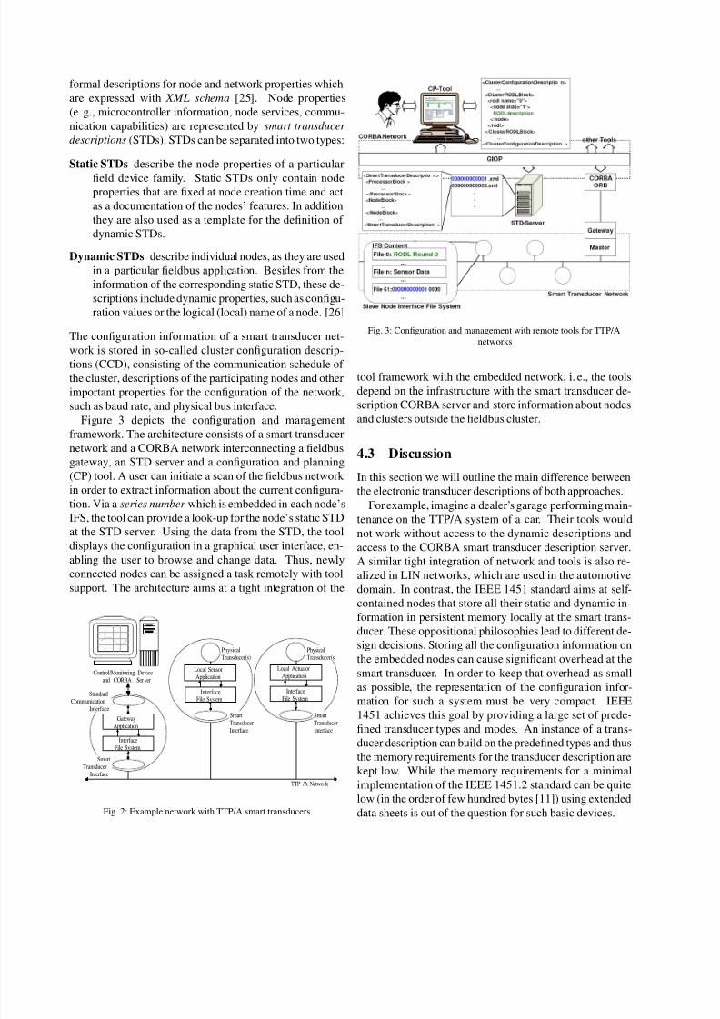
Figure 2 depicts a sample network with two TTP/A smart
transducers and a gateway node. The local application of
a smart transducer maps the functionality of the transducerinto an interface file system (IFS), i. e., a set of small mem-
ory elements that are typically located at the local memory
of the smart transducer’s microcontroller. The IFS is hierar-
chically structured into files and records enabling a unique
addressing scheme. The main advantage of this approach
is that such files and records are easily translated into vari-
ous bus protocols, thus enabling an easy implementation of
gateway nodes supporting interoperability between various
systems. However, it may be difficult to map all capabilities
of a smart device in terms of reads and writes of memory lo-
cations [23]. Therefore, the IFS provides a further operation
named execute that is used to trigger a function assigned to
a record, like “update sensor measurement”, etc. The IFSconcept is very resource-efficient. A typical smart trans-
ducer will fit into an 8 bit RISC microcontroller with 128
bytes RAM and 4 Kbytes of flash ROM [2].
Pitzek and Elmenreich [24] describe a configuration and
management framework for the low-cost real-time fieldbus
network TTP/A (according to the OMG Smart Transduc-
ers Interface Specification [14]). The approach consists of
8/3/2019 10.1.1.14.8516(2)
http://slidepdf.com/reader/full/10111485162 5/7
formal descriptions for node and network properties which
are expressed with XML schema [25]. Node properties
(e. g., microcontroller information, node services, commu-
nication capabilities) are represented by smart transducer
descriptions (STDs). STDs can be separated into two types:
Static STDs describe the node properties of a particular
field device family. Static STDs only contain nodeproperties that are fixed at node creation time and act
as a documentation of the nodes’ features. In addition
they are also used as a template for the definition of
dynamic STDs.
Dynamic STDs describe individual nodes, as they are used
in a particular fieldbus application. Besides from the
information of the corresponding static STD, these de-
scriptions include dynamic properties, such as configu-
ration values or the logical (local) name of a node. [26]
The configuration information of a smart transducer net-
work is stored in so-called cluster configuration descrip-
tions (CCD), consisting of the communication schedule of
the cluster, descriptions of the participating nodes and other
important properties for the configuration of the network,
such as baud rate, and physical bus interface.
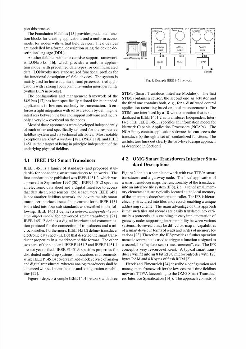
Figure 3 depicts the configuration and management
framework. The architecture consists of a smart transducer
network and a CORBA network interconnecting a fieldbus
gateway, an STD server and a configuration and planning
(CP) tool. A user can initiate a scan of the fieldbus network
in order to extract information about the current configura-
tion. Via a series number which is embedded in each node’s
IFS, the tool can provide a look-up for the node’s static STD
at the STD server. Using the data from the STD, the tooldisplays the configuration in a graphical user interface, en-
abling the user to browse and change data. Thus, newly
connected nodes can be assigned a task remotely with tool
support. The architecture aims at a tight integration of the
Control/Monitoring DeviceandCORBASer ver
TTP/A Network
PhysicalTransducer(s)
PhysicalTransducer(s)
SmartTransducerInterface
SmartTransducerInterface
SmartTransducer
Interface
StandardCommunication
Interface
GatewayApplication
InterfaceFile System
InterfaceFile System
InterfaceFile System
Local SensorApplication
Local ActuatorApplication
Fig. 2: Example network with TTP/A smart transducers
Fig. 3: Configuration and management with remote tools for TTP/A
networks
tool framework with the embedded network, i. e., the tools
depend on the infrastructure with the smart transducer de-
scription CORBA server and store information about nodes
and clusters outside the fieldbus cluster.
4.3 Discussion
In this section we will outline the main difference between
the electronic transducer descriptions of both approaches.
For example, imagine a dealer’s garage performing main-
tenance on the TTP/A system of a car. Their tools would
not work without access to the dynamic descriptions andaccess to the CORBA smart transducer description server.
A similar tight integration of network and tools is also re-
alized in LIN networks, which are used in the automotive
domain. In contrast, the IEEE 1451 standard aims at self-
contained nodes that store all their static and dynamic in-
formation in persistent memory locally at the smart trans-
ducer. These oppositional philosophies lead to different de-
sign decisions. Storing all the configuration information on
the embedded nodes can cause significant overhead at the
smart transducer. In order to keep that overhead as small
as possible, the representation of the configuration infor-
mation for such a system must be very compact. IEEE
1451 achieves this goal by providing a large set of prede-fined transducer types and modes. An instance of a trans-
ducer description can build on the predefined types and thus
the memory requirements for the transducer description are
kept low. While the memory requirements for a minimal
implementation of the IEEE 1451.2 standard can be quite
low (in the order of few hundred bytes [11]) using extended
data sheets is out of the question for such basic devices.
8/3/2019 10.1.1.14.8516(2)
http://slidepdf.com/reader/full/10111485162 6/7
The STD and CCD descriptions for the TTP/A protocol
are very generic and need more memory. For example the
size of uncompressed static STDs for the smart transducers
used in the smart car case study is between 5 and 15 Kbytes.
The uncompressed CCD for this case study had a size of
124 Kbytes [24]. However, this information is stored at
personal computers, while the smart transducer nodes con-
tain only a unique identification number and some config-uration parameters that are necessary for operation. The
unique identification number serves as reference to the ac-
cording information that is stored as STDs and CCD outside
the cluster. This approach comes with two advantages:
• First, the overhead at the node is very low. Current
low-cost microcontrollers provide RAM or EEPROM
memory of around 128 bytes. This will not suffice
to store more than the most basic parts of data-sheets
according to the IEEE 1451.2 standard without extra
hardware. With TTP/A, only the ROM memory for
storing the identification number is necessary.
• Second, instead of implicitly representing the node-
information with many predefined data structures
mapped to a compact format, we have an explicit rep-
resentation of the information in a well-structured and
easy to understand way. Since the system hosting the
configuration tool usually provides memory for sev-
eral megabytes of data, the specification of transducer
types and services using generic XML constructs is no
major limiting factor for the framework. The generic
format also improves the openness of the system for
future extensions of transducer or service types.
5 Summary and Conclusion
This paper presented basic principles of smart transducers
and shortly examined multiple solutions for communica-
tion in transducer networks. Furthermore, we compared
two different standardized smart transducer interfaces, the
IEEE 1451.2 standard for smart transducer interfaces and
the OMG STI standard. The standards were examined with
respect to design decisions for dealing with configuration
and handling configuration information.
The OMG STI standard supports the configuration of time-triggered communication schedules, which makes it
suitable for connecting smart transducers to hard real-time
systems. The OMG STI standard consists of the TTP/A
fieldbus network and a fieldbus to CORBA interface specifi-
cation. For TTP/A there exists a framework that introduces
smart transducer and cluster configuration descriptions that
enable a computer supported configuration.
IEEE 1451 does not specify an according fieldbus pro-
tocol. The transducer electronic data sheets of IEEE 1451
are more compact than the smart transducer descriptions of
TTPA, however since IEEE 1451 favors the introduction of
self-contained nodes that keep the configuration data phys-
ically associated to the nodes, memory requirements for
IEEE 1451 will be higher at the smart transducer. In general
it depends on the area of application which approach suitsbest.
6 Acknowledgments
We would like to give special thanks to our colleagues
Thomas Losert, Roman Obermaisser, and Martin Schlager
who made fruitful comments on an earlier version of this
paper. This work was supported in part by the Hochschulju-
bilaumsstiftung der Stadt Wien via project CoMa (H-
965/2002) and by the European IST project DSoS under
contract No IST-1999-11585.
7 References
[1] W. H. Ko and C. D. Fung. VLSI and intelligent trans-
ducers. Sensors and Actuators, (2):239–250, 1982.
[2] H. Kopetz, M. Holzmann, and W. Elmenreich. A uni-
versal smart transducer interface: TTP/A. Interna-
tional Journal of Computer System Science & Engi-
neering, 16(2):71–77, March 2001.
[3] S. Poledna, H. Angelow, M. Gluck, M. Pisecky,
I. Smaili, G. Stoger, C. Tanzer, and G. Kroiss. TTP
two level design approach: Tool support for com-
posable fault-tolerant real-time systems. SAE World
Congress 2000, Detroit, Michigan, USA, March 2000.
[4] H. Kopetz. Software engineering for real-time: A
roadmap. In Proceedings of the IEEE Software En-
gineering Conference, Limmerick, Ireland, 2000.
[5] M. Felser and T. Sauter. The fieldbus war: History or
short break between battles? In Proceedings of the
4rd IEEE International Workshop on Factory Com-
munication Systems, pages 73–79, Vasteras, Sweden,
August 2002.
[6] International Standardization Organization (ISO).
ISO/IEC 7498-1:1994 - Information technology –
Open Systems Interconnection – Basic Reference
Model: The Basic Model, 1994. available at
http://www.iso.ch.
8/3/2019 10.1.1.14.8516(2)
http://slidepdf.com/reader/full/10111485162 7/7
[7] D. Loy, D. Dietrich, and H.-J. Schweinzer, editors.
Open Control Networks. Kluwer Academic Publish-
ing, October 2001.
[8] J. J. Pinto. A neutral instrumentation vendor’s per-
spective. ISA Proceedings ’94 and Intech July ’95,
July 1995.
[9] DKE Deutsche Kommission Elektrotechnik Elek-
tronik Informationstechnik im DIN und VDE. Infor-
mation about the International Fieldbus Standards Se-
ries IEC 61158 and 61784, February 2002. Available
at http://www.dke.de.
[10] I. Nather. Profibus dominiert noch immer klar.
Markt&Technik - Die Wochenzeitung f ur Elektronik
und Informati onstechnik , 22, May 2002.
[11] P. Conway, D. Heffernan, B. O’Mara, D. P. Burton,
and T. Miao. IEEE 1451.2: An interpretation and
example interpretation. In Proceedings of the Instru-
mentation and Measurement Technology Conference,
pages 535–540, Baltimore, MD, USA, May 2000.
[12] L. H. Eccles. A brief description of IEEE P1451.2.
Sensors Expo, May 1998.
[13] Object Management Group (OMG). Smart Trans-
ducers Interface Request for Proposal, December
2000. Available at http://www.omg.org as document
orbos/2000-12-13.
[14] Object Management Group (OMG). Smart Trans-
ducers Interface Final Adopted Specification, August
2002. Available at http://www.omg.org as documentptc/2002-10-02.
[15] Fieldbus technical overview - understanding FOUN-
DATION fieldbus technology, 2001. Available at
http://www.fieldbus.org.
[16] Electronic Industry Alliance (EIA). Control Network
Specification. EIA Standard 709.1, March 1998.
[17] Audi AG, BMW AG, DaimlerChrysler AG, Motorola
Inc. Volcano Communication Technologies AB, Volk-
swagen AG, and Volvo Car Corporation. LIN spec-
ification and LIN press announcement. SAE World
Congress Detroit, http://www.lin-subbus.org, 1999.
[18] L.-B. Fredriksson. A CAN Kingdom - Revision 3.01.
available at http://www.cankingdom.org, 1995.
[19] Bosch. OSEK/VXD operating system - version
2.1 revision 1. available at http://www-iiit.etec.uni-
karlsruhe.de/ ∼osek/, Dec. 2000.
[20] Institute of Electrical and Electronics Engineers, Inc.
IEEE Std 1451.2-1997, Standard for a Smart Trans-
ducer Interface for Sensors and Actuators - Trans-
ducer to Micro-processor Communication Protocols
and Transducer Electronic Data Sheet (TEDS) For-
mats, September 1997.
[21] J. Warrior. IEEE P1451 network capable applicationprocessor information model. Proceedings Sensors
Expo Anaheim, pages 15–21, April 1996.
[22] S.Chen and K.Lee. A mixed-mode smart transducer
interface for sensors and actuators. Sound & Vibra-
tion, April 1998.
[23] J. Warrior. Open systems: Reality or illusion? Sensors
Magazine, September 1998.
[24] S. Pitzek and W. Elmenreich. Configuration and man-
agement of a real-time smart transducer network. Re-
search Report 6/2003, Technische Universitat Wien,
Institut fur Technische Informatik, Vienna, Austria,2003.
[25] World Wide Web Consortium (W3C). XML
Schema Part 0: Primer , May 2001. Available at
http://www.w3.org.
[26] S. Pitzek. Description mechanisms supporting the
configuration and management of TTP/A fieldbus sys-
tems. Master’s thesis, Technische Universitat Wien,
Institut fur Technische Informatik, Vienna, Austria,
2002.


![[XLS] · Web view3 3 3 3 3 3 3 3 3 3 2 4 4 4 4 4 2 2 2 3 3 3 3 3 3 3 3 3 2 2 2 2 2 2 2 2 2 2 2 2 2 2 2 2 2 2 2 2 3 3 3 3 3 3 3 3 3 3 3 2 2 2 2 4 4 4 4 4 4 4 4 4 4 2 2 2 2 2 2 2 2](https://img.pdfslide.tips/doc/110x75/5b1aa0e07f8b9a3c258de1b1/xls-web-view3-3-3-3-3-3-3-3-3-3-2-4-4-4-4-4-2-2-2-3-3-3-3-3-3-3-3-3-2-2-2.jpg)