Embed Size (px)
Citation preview
11
5 1
74
05
17/
1310
- 1
.0
Mega 370/100 W
Mega 370/100 D
Mega 490/50 W
Mega 490/50 D
Mega 490/100 W
Mega 490/100 D
Mega 500/150 D
Mega 550/200 D
Mega 650/200 D
Originalbetriebsanleitung. . . . . . . . . . . . . . . . . . . . . . . . . . 2
Original operating instructions . . . . . . . . . . . . . . . . . . . . . 10
Instructions d’utilisation originales . . . . . . . . . . . . . . . . . . 17
Manuale d’uso originale. . . . . . . . . . . . . . . . . . . . . . . . . . 25
Origineel gebruikaanwijzing. . . . . . . . . . . . . . . . . . . . . . . 33
Manual de instrucciones original . . . . . . . . . . . . . . . . . . . 41
Manual de serviço original. . . . . . . . . . . . . . . . . . . . . . . . 49
Original brugsvejledning . . . . . . . . . . . . . . . . . . . . . . . . . 57
Original instruksjonsbok . . . . . . . . . . . . . . . . . . . . . . . . . 64
Original bruksanvisning . . . . . . . . . . . . . . . . . . . . . . . . . . 71
Alkuperäiskäyttöohje . . . . . . . . . . . . . . . . . . . . . . . . . . . . 78
Originál használati utasítás . . . . . . . . . . . . . . . . . . . . . . . 86
Oryginalna instrukcja obs!ugi. . . . . . . . . . . . . . . . . . . . . . 94
"#$%$&'()&*+ #,-*.*/01.* 2* 3-02(,'1'4$$ . . . . . . 102
567898:;< <=>?@AB CD@8<:6?EFG. . . . . . . . . . . . . . . . . . 110
0031_1_1v1IVZ.fm
ENGLISH
10
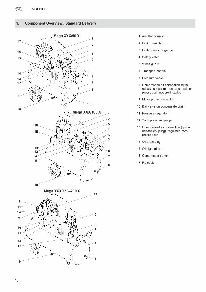
1. Component Overview / Standard Delivery
1 Air filter housing
2 On/Off switch
3 Outlet pressure gauge
4 Safety valve
5 V-belt guard
6 Transport handle
7 Pressure vessel
8 Compressed air connection (quick-
release coupling), non-regulated com-
pressed air, not pre-installed
9 Motor protection switch
10 Ball valve on condensate drain
11 Pressure regulator
12 Tank pressure gauge
13 Compressed air connection (quick-
release coupling), regulated com-
pressed air
14 Oil drain plug
15 Oil sight glass
16 Compressor pump
17 Re-cooler
Mega XXX/50 X1
2
3
4
5
6
7
8
9
10
11
12
13
15
16
17
14
Mega XXX/100 X
Mega XXX/150–200 X
1
2
5
3
12
13
10
9
4
8
11
14
15
16
7
6
13
16
5
8
11
4
14
15
3
12
2
1
10
76
13
I_0023en1A.fm 1.4.10 Original operating instructions
ENGLISH
11
1. Component Overview /
Standard Delivery...................10
2. EC Declaration of
Conformity ..............................11
3. Please Read First! ..................11
4. Safety.......................................11
4.1 Specified conditions of use.......11
4.2 General safety instructions.......11
4.3 Symbols on the machine ..........12
4.4 Safety devices ..........................13
5. Operation ................................13
5.1 Prior to initial operation.............13
5.2 Installation ................................13
5.3 Mains connection .....................13
5.4 Generating compressed air ......13
6. Care and Maintenance ...........14
6.1 Periodic maintenance...............14
6.2 Machine storage.......................15
7. Troubleshooting .....................15
8. Repairs ....................................15
9. Environmental Protection......15
10. Technical Data ........................16
We hereby declare that this machine complies with the basic requirements and provisions of the applicable direc-tives.
These operating instructions have been written so that you can quickly learn how to operate your device safely. Here is how to read the instructions:
– Read these instructions completely before use. Pay special attention to the safety information.
– These instructions are intended for persons with basic technical knowl-edge in the handling of machines such as the one described here. In-experienced persons are strongly advised to seek competent advice and guidance from an experienced person before operating this ma-chine.
– Retain all documents delivered to-gether with this device so that you and other users have access to the relevant information at all times. Re-tain proof of purchase for any future warranty claims.
– If you lend or sell this device be sure to have these Operating In-structions go with it.
– The manufacturer is not liable for any damage arising from disregard of these instructions.
Information in these Operating Instruc-
tions is denoted as follows:
A Danger!
Risk of personal injury or environmental
damage.
B Risk of electric shock!
Risk of personal injury by electric
shock.
A Caution!
Risk of material damage.
3 Note:
Additional information.
– Numbers in illustrations (1, 2, 3
etc.)
– denote component parts;
– are consecutively numbered;
– relate to the corresponding number(s) in brackets (1), (2), (3) etc. in the neighbouring text.
– Numbered steps must carried out in sequence.
– Instructions which can be carried out in any sequence are indicated by a bullet point (•).
– Listings are preceded by a dash (–).
4.1 Specified conditions of use
This machine is designed to generate
compressed air required for the opera-
tion of air tools. The machine should
only be used under supervision.
Any use for medical purposes, food
processing or filling of oxygen cylinders
for breathing equipment is not permit-
ted.
Gas or dust which is explosive, com-bustible or detrimental to health may not be compressed. Operation in explo-siver or dusty environments is prohibit-ed.
Any other use is not as specified. Use not as specified, alteration of the ma-chine or use of parts that are not ap-proved by the equipment manufacturer can cause unforeseeable damage!
Children, juveniles and persons not in-structed in use of this machine are not permitted to operate the machine or any air tools connected to it.
4.2 General safety instruc-tions
When using this electric tool ob-serve the following safety instruc-tions to exclude the risk of personal injury or material damage.
Please also observe the special safety instructions in the respective chapters.
Keep all documents supplied with the machine for future reference.
Observe the statutory accident in-surance institution guidelines and regulations for the prevention of ac-cidents pertaining to the operation of air compressors and air tools where applicable.
Observe the legal regulations re-garding operation of systems sub-ject to technical inspections.
When operating and storing the ma-chine be aware that leaking conden-sate and operating materials can contaminate the environment and lead to environmental damage.
A General hazard!
Keep your work area tidy – a messy work area invites accidents.
Be alert. Know what you are doing. Set out to work with reason. Do not operate the electric tool while under the influence of drugs, alcohol or medication.
Consider environmental conditions.
Keep work area well lighted.
Prevent adverse body positions. En-sure firm footing and keep your bal-ance at all times.
Do not operate the electric tool near inflammable liquids or gases.
Keep bystanders, particularly chil-dren, out of the work area. Do not permit other persons to touch the tool or power cable while the elec-tric tool is running.
Table of Contents
2. EC Declaration of Con-formity
3. Please Read First!
4. Safety
ENGLISH
12
Do not overload the electric tool – use it only within the performance range it was designed for (see 'Technical Data').
B Danger! Risk of electric
shock!
Do not expose the electric tool to
rain.
Do not operate the electric tool in a
damp or wet environment.
Prevent body contact with earthed
objects such as radiators, pipes,
cooking stoves or refrigerators
when operating this electric tool.
Do not use the power cable for pur-
poses it is not intended for.
A Risk of personal injury by es-
caping compressed air and parts
hurled about by escaping air!
Never direct compressed air against persons or animals!
Ensure all air tools and accessories used are designed for the working pressure or are supplied via a pres-sure regulator.
Please note that when the quick coupler is disconnected the com-pressed air contained in the pres-sure hose will escape all of a sud-den. You should therefore firmly hold the air hose when disconnect-ing it.
Ensure all screwed connections are fully tightened at all times.
Do not attempt to repair the device yourself! Only trained specialists are permitted to service or repair com-pressors, pressure vessels and air tools.
A Hazard generated by lubricat-
ed compressed air!
Use oil-saturated compressed air
only for air tools requiring such sup-
ply.
Do not use an air hose used to sup-
ply compressed air containing oil to
supply air tools not designed for op-
eration on compressed air contain-
ing oil.
Do not fill tires with compressed air
containing oil.
A Risk of burns from the surfac-
es of parts carrying compressed air!
Let tool cool off before servicing.
A Risk of personal injury and
crushing by moving parts!
Do not operate the compressor
without installed guards.
Please note that the compressor will
start automatically when the pres-
sure falls off to minimum! – Discon-
nect from power supply prior to any
servicing.
When turning ON the machine (e.g.
after servicing) ensure that no tools
or loose parts are left on or in the
machine.
A Hazard generated by insuffi-
cient personal protective equipment!
Wear hearing protection.
Wear safety glasses.
Wear mask respirator when work
generates dust or mist detrimental
to health.
Wear suitable work clothes. When
working outdoors wearing of non-
slip shoes is recommended.
B Hazard generated by electric
tool defects!
Keep electric tool and accessories in good repair. Observe the mainte-nance instructions.
Prior to use check the electric tool for possible damage: before using the electric tool carefully check safety devices, protection devices and any slightly damaged parts for proper function as specified. Dam-aged machines must be properly re-paired before use.
Check to see that all moving parts work properly and do not jam. All parts must be correctly installed and meet all conditions necessary for the proper operation of the electric tool.
Damaged protection devices or parts must be repaired or replaced by an authorised repair centre.
Have damaged switches replaced by a customer service centre.
Do not operate electric tool if the switch cannot be turned ON or OFF.
Keep handles dry and free of oil and grease.
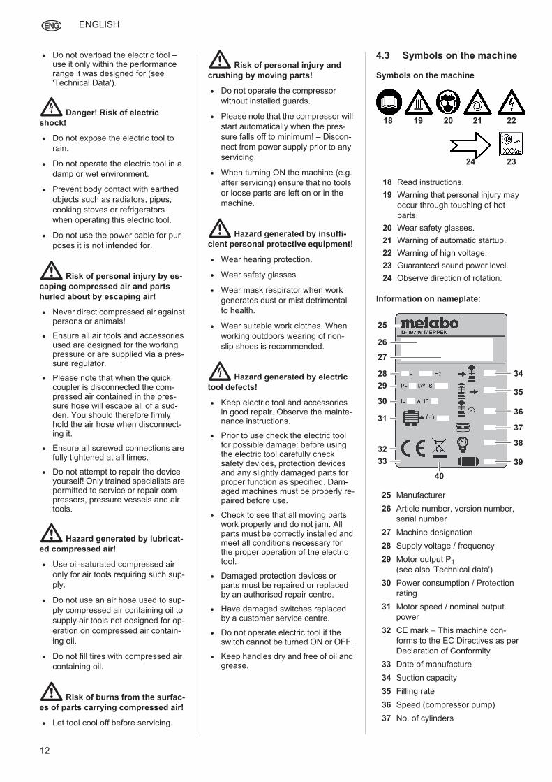
4.3 Symbols on the machine
Symbols on the machine
Information on nameplate:
18 Read instructions.
19 Warning that personal injury may
occur through touching of hot
parts.
20 Wear safety glasses.
21 Warning of automatic startup.
22 Warning of high voltage.
23 Guaranteed sound power level.
24 Observe direction of rotation.
25 Manufacturer
26 Article number, version number,
serial number
27 Machine designation
28 Supply voltage / frequency
29 Motor output P1
(see also 'Technical data')
30 Power consumption / Protection
rating
31 Motor speed / nominal output
power
32 CE mark – This machine con-
forms to the EC Directives as per
Declaration of Conformity
33 Date of manufacture
34 Suction capacity
35 Filling rate
36 Speed (compressor pump)
37 No. of cylinders
18 19 20 21 22
2324
27
28
29
30
32
35
36
37
38
31
34
39
40
33
25
26
ENGLISH
13
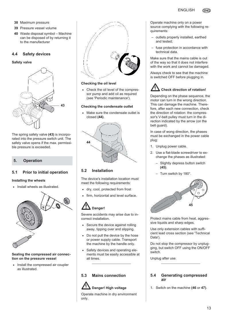
4.4 Safety devices
Safety valve
The spring safety valve (43) is incorpo-
rated into the pressure switch unit. The
safety valve opens if the max. permissi-
ble pressure is exceeded.
5.1 Prior to initial operation
Installing the wheels
Install wheels as illustrated.
Sealing the compressed air connec-
tion on the pressure vessel
Install the compressed air coupler
as illustrated.
Checking the oil level
Check the oil level of the compres-
sor pump and add oil as required
(see 'Periodic maintenance').
Checking the condensate outlet
Make sure the condensate outlet is
closed (44).
5.2 Installation
The device's installation location must
meet the following requirements:
dry, cool, protected from frost
firm, horizontal and level surface.
A Danger!
Severe accidents may arise due to in-
correct installation.
Secure the device against rolling
away, tipping over and slipping.
Do not pull the device by the hose
or power supply cable. Transport
the machine by the handle only.
Safety devices and operating ele-
ments must be easily accessible at
all times.
5.3 Mains connection
B Danger! High voltage
Operate machine in dry environment
only.
Operate machine only on a power
source complying with the following re-
quirements:
– outlets properly installed, earthed
and tested;
– fuse protection in accordance with
technical data.
Make sure that the mains cable is out
of the way so that it does not interfere
with the work and cannot be damaged.
Always check to see that the machine
is switched OFF before plugging in.
B Check direction of rotation!
Depending on the phase sequence, the
motor can turn in the wrong direction.
This can damage the machine. There-
fore, after each new connection, check
the direction of rotation: the compres-
sor's V-belt pulley must turn in the di-
rection indicated by the arrow (on the
belt guard).
In case of wong direction, the phases
must be exchanged in the power cable
plug:
1. Unplug power cable.
2. Use a flat-blade screwdriver to ex-
change the phases as illustrated:
– Slightly depress button switch
(45).
– Turn switch by 180°.
Protect mains cable from heat, aggres-
sive liquids and sharp edges.
Use only extension cables with suffi-
cient lead cross section (see 'Technical
Data').
Do not stop the compressor by unplug-
ging, but switch OFF using the ON/OFF
switch.
Unplug after use.
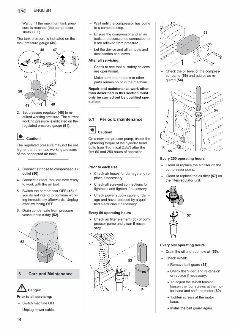
5.4 Generating compressed air
1. Switch on the machine (46 or 47).
38 Maximum pressure
39 Pressure vessel volume
40 Waste disposal symbol – Machine
can be disposed of by returning it
to the manufacturer
5. Operation
43
44
45
ENGLISH
14
Wait until the maximum tank pres-
sure is reached (the compressor
shuts OFF).
The tank pressure is indicated on the
tank pressure gauge (49).
2. Set pressure regulator (48) to re-
quired working pressure. The current
working pressure is indicated on the
regulated pressure gauge (51).
A Caution!
The regulated pressure may not be set
higher than the max. working pressure
of the connected air tools!
3. Connect air hose to compressed air
outlet (50).
4. Connect air tool. You are now ready
to work with the air tool.
5. Switch the compressor OFF (46) if
you do not intend to continue work-
ing immediately afterwards. Unplug
after switching OFF.
6. Drain condensate from pressure
vessel once a day (52).
A Danger!
Prior to all servicing:
– Switch machine OFF.
– Unplug power cable.
– Wait until the compressor has come
to a complete stop.
– Ensure the compressor and all air
tools and accessories connected to
it are relieved from pressure.
– Let the device and all air tools and
accessories cool down.
After all servicing:
– Check to see that all safety devices
are operational.
– Make sure that no tools or other
parts remain on or in the machine.
Repair and maintenance work other
than described in this section must
only be carried out by qualified spe-
cialists.
6.1 Periodic maintenance
A Caution!
On a new compressor pump, check the
tightening torque of the cylinder head
bolts (see 'Technical Data') after the
first 50 and 250 hours of operation.
Prior to each use
Check air hoses for damage and re-
place if necessary.
Check all screwed connections for
tightness and tighten if necessary.
Check power supply cable for dam-
age and have replaced by a quali-
fied electrician if necessary.
Every 50 operating hours
Check air filter element (53) of com-
pressor pump and clean if neces-
sary.
Check the oil level of the compres-
sor pump (56) and add oil as re-
quired (54).
Every 250 operating hours
Clean or replace the air filter on the
compressor pump.
Clean or replace the air filter (57) on
the filter/regulator unit.
Every 500 operating hours
Drain the oil and add new oil (55).
Check V-belt:
Remove belt guard (58).
Check the V-belt and re-tension
or replace if necessary.
To adjust the V-belt tension,
loosen the four screws at the mo-
tor base and shift the motor (59).
Tighten screws at the motor
base.
Install the belt guard again.
6. Care and Maintenance
49
50
46
48
51
47
52
53
53
54
5556
57
ENGLISH
15
Every 1000 operating hours
Have unit serviced by an authorised
service centre. This will extend the
compressor's service life considerably.
6.2 Machine storage
1. Switch unit OFF and unplug.
2. Release pressure from tank and all connected air tools.
3. Drain condensate from pressure vessel .
4. Store device in such way that it can-not be started by unauthorised per-sons.
A Caution!
Do not store or transport machine un-
protected outdoors or in a damp envi-
ronment.
Do not lay machine on its side for trans-
port or storage.
A Danger!
Prior to all servicing:
– Switch machine OFF.
– Unplug power cable.
– Wait until the compressor has come
to a complete stop.
– Ensure the compressor and all air
tools and accessories connected to
it are relieved from pressure.
– Let the device and all air tools and accessories cool down.
After all servicing:
– Reactivate all safety devices and ensure they are operational.
– Make sure that no tools or other parts remain on or in the machine.
Compressor does not run:
No mains voltage.
– Check cables, plug, outlet and mains fuse.
Mains voltage too low.
– Use only extension cables of suf-ficient lead cross section (see 'Technical Data'). When the ma-chine is cold avoid extension ca-bles and relieve the pressure in the pressure tank.
Compressor was stopped by un-plugging.
– Switch compressor OFF and then ON again using the On/Off switch.
Motor has overheated, e.g. due to
insufficient cooling (cooling fins cov-
ered).
– First switch off the compressor using the ON/OFF switch and al-low to cool.
– Eliminate the cause of overheat-ing.
Only for version with AC motor:
– Check the motor protection switch; reset if necessary.
– Switch the compressor back on.
Compressor runs but does not build
up sufficient pressure.
Condensate drain cock of pressure
tank leaky.
– Check gasket of drain cock(s); replace if necessary.
– Tighten drain cock(s) hand-tight.
Check valve leaky.
– Have check valve serviced by qualified service centre.
Air tool is not supplied with suffi-cient pressure.
Pressure regulator not opened wide enough.
– Open pressure regulator more.
Hose connection between compres-sor and air tool leaky.
– Check air hoses; replace defec-tive parts if necessary.
Further work on the machine should only be carried out by a qualified electrician or the Service Centre in your country.
A Danger!
Repairs to electric tools must be carried
out by qualified electricians only!
Electric tools in need of repair can be sent to the Service Centre in your coun-try. See Spare Parts List for address.
Please attach a description of the fault to the power tool.
A Danger!
The condensation water from the pres-
sure vessel contains oil residues. Dis-
pose of the condensation water in an
environmentally-oriented manner at an
appropriate collection point!
A Danger!
Dispose of the waste oil from the com-
pressor pump in an environmentally-ori-
ented manner at an appropriate collec-
tion point!
The tool's packaging can be 100% re-cycled.
Worn out machines and accessories contain considerable amounts of valua-ble raw and plastic materials, which can be recycled.
These instructions are printed on paper
produced with an elemental chlorine-
free bleaching process.
7. Troubleshooting
58
59
8. Repairs
9. Environmental Protec-tion
ENGLISH
16
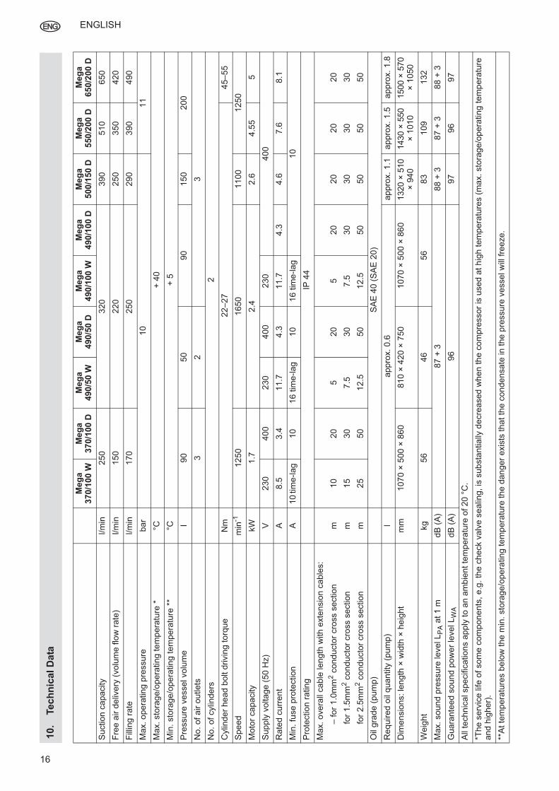
10
.Tec
hn
ical
Da
ta
Meg
a
370/1
00
WM
eg
a
370/1
00
DM
eg
a
490/5
0 W
Meg
a
490/5
0 D
Meg
a
490/1
00
WM
eg
a
490/1
00
DM
eg
a
500/1
50 D
Meg
a
550
/200 D
Meg
a
65
0/2
00 D
Suction
ca
pacity
l/m
in
250
320
39
05
10
650
Fre
e a
ir d
eliv
ery
(vo
lum
e f
low
rate
) l/m
in
150
220
25
03
50
420
Fill
ing r
ate
l/m
in
170
250
29
03
90
490
Max. o
pera
tin
g p
ressure
bar
10
11
Max. sto
rag
e/o
pera
ting te
mp
era
ture
*°C
+40
Min
. sto
rage/o
pera
ting t
em
pera
ture
**
°C+
5
Pre
ssure
vessel volu
me
l 90
50
90
150
200
No
. of a
ir o
utlets
3
23
No
. of cylin
de
rs
2
Cylin
de
r he
ad b
olt d
rivin
g to
rque
Nm
22
–27
45–55
Spe
ed
min
-1
12
50
16
50
1100
125
0
Moto
r capacity
kW
1.7
2
.42.6
4.5
55
Sup
ply
voltage
(50
Hz)
V
230
40
02
30
400
230
400
Ra
ted
cu
rre
nt
A
8.5
3.4
11
.74
.31
1.7
4.3
4.6
7.6
8.1
Min
. fu
se p
rote
ction
A
10
tim
e-l
ag
10
16 t
ime-lag
10
16
tim
e-la
g10
Pro
tection
ratin
gIP
44
Max. o
vera
ll cab
le len
gth
with e
xte
nsio
n c
able
s:
– fo
r 1.0
mm
2 c
onducto
r cro
ss s
ection
m10
20
520
520
20
20
20
for
1.5
mm
2 c
on
ducto
r cro
ss s
ection
m1
530
7.5
30
7.5
30
30
30
30
for
2.5
mm
2 c
on
ducto
r cro
ss s
ection
m2
550
12.5
50
12.5
50
50
50
50
Oil
gra
de (
pum
p)
SA
E 4
0 (
SA
E 2
0)
Re
quire
d o
il qu
antity
(pu
mp
) l
appro
x.
0.6
appro
x.
1.1
appro
x.
1.5
app
rox.
1.8
Dim
ensio
ns: le
ngth
× w
idth
× h
eig
ht
mm
1070
×5
00
×86
0810
×4
20
×75
01070
×5
00
×86
01320
×510
×940
1430
×550
×1
010
1500
×570
×1050
Weig
ht
kg
56
46
56
83
109
132
Max. so
und p
ressu
re level LPA a
t 1
mdB
(A
)87 +
388 +
387
+ 3
88
+ 3
Guara
nte
ed s
oun
d p
ow
er
level LWA
dB
(A
)96
97
96
97
All
techn
ical specific
ations a
pp
ly to a
n a
mb
ient
tem
pera
ture
of 2
0°C
.
*The
serv
ice
life
of som
e c
om
pon
ents
, e.g
. th
e c
heck v
alv
e s
ealin
g, is
sub
sta
ntially
de
cre
ased w
hen th
e c
om
pre
ssor
is u
sed a
t h
igh
tem
pera
ture
s (
max. sto
rag
e/o
pera
ting te
mp
era
ture
an
d h
igher)
.
**A
t te
mpera
ture
s b
elo
w t
he m
in. sto
rag
e/o
pera
ting te
mp
era
ture
the d
an
ger
exis
ts tha
t th
e c
onde
nsate
in t
he p
ressure
vessel w
ill f
reeze.


![[ROBIX] Naruto 490](https://img.pdfslide.tips/doc/110x75/568bdd001a28ab2034b441fd/robix-naruto-490.jpg)