Embed Size (px)
Citation preview

7/31/2019 11E-YorkBucketElevatorM16-M24LeggingConstructionManual (1)
http://slidepdf.com/reader/full/11e-yorkbucketelevatorm16-m24leggingconstructionmanual-1 1/84
P/N 10230002 rev 6-09 [1]
Bucket Elevator M16 - M24 13”[0.33 m] x 9”[0.23 m] LEGGING
CONSTRUCTION AND OWNER’S MANUAL

7/31/2019 11E-YorkBucketElevatorM16-M24LeggingConstructionManual (1)
http://slidepdf.com/reader/full/11e-yorkbucketelevatorm16-m24leggingconstructionmanual-1 2/84
M16 - M24 Bucket Elevator, 13 x 9 Legging 10230002 6-09 [1]
2
The Symbol shown below is used to call your attention to instructionsconcerning your personal safety. Watch this symbol - it points outimportant safety precautions. It means “ATTENTION” - Become Alert!Your Personal Safety Is Involved! Read the message that followsand be alert to the possibility of personal injury or death.
Your Personal Safety Is Involved
A copy of this manual should be available at all times to the owner/operator. Additionalcopies may be requested from the company at the address shown on the back cover.Please reference part number #10230002 when requesting additional copies.
Please Contact MFS/YORK/STORMOR or Your DealerIf You Have Any Questions Concerning This Manual
Keep This Manual In A Safe Place Available For Future Reference
Be Alert!
The safety and performance of this elevator, constructed and readied foroperation will be affected by the installation and construction personnel.Elevators generally involve extreme heights and high winds. Carefulconsideration must be given to the structural requirements. We therefore
highly recommend the use of a skilled construction company with a qualifiedstructural engineer. MFS/YORK/STORMOR cannot be responsible for theconstruction of the elevator. The information obtained in this manual isoffered only as a convenience to the installer. No liability is expressed orimplied toward the installation.

7/31/2019 11E-YorkBucketElevatorM16-M24LeggingConstructionManual (1)
http://slidepdf.com/reader/full/11e-yorkbucketelevatorm16-m24leggingconstructionmanual-1 3/843
M16 - M24 Bucket Elevator, 13 x 9 Legging 10230002 6-09 [1]
PREFACE
You have purchased the finest bucket elevator manufactured today. The following informationis intended as a guide for: bucket elevator pre-assembly, proper construction, and safe andproper use after construction.
A G E N U I N E
P R O D U C T
GLOBAL INDUSTRIES, INC.
General Safety Statement
Your safety and the safety of others associated with your grain system equipment is ofprime concern to us at MFS/YORK/STORMOR. We wrote this manual to help you tobetter understand how to safely build and use this YORK bucket elevator.
It is your responsibility as the owner, builder, operator, or supervisor, to know whatspecific requirements, precautions, and hazards exist and to make these known to all
personnel working with the equipment or in the area, so that they too may take anynecessary safety precautions that may be required!
Failure to read this Manual and its Safety Instructions by all personnel is a misuse ofthe equipment. We want you as our partner in safety!
All personnel, including construction personnel, must read and understand allequipment Operator’s Manuals before starting bucket elevator construction!

7/31/2019 11E-YorkBucketElevatorM16-M24LeggingConstructionManual (1)
http://slidepdf.com/reader/full/11e-yorkbucketelevatorm16-m24leggingconstructionmanual-1 4/84
M16 - M24 Bucket Elevator, 13 x 9 Legging 10230002 6-09 [1]
4
Be Alert ...................................................................2
General Safety Statement .....................................3
Warranty .................................................................6
1 Maintenance .................................................7
2 Safety ............................................................8
Grain Dust Explosions .............................................. 10
Operating Safety .......................................................12
Lock-Out ................................................................... 13
Warning Decals ........................................................ 14
3 Pit Drawings ...............................................16
4 Specifications .............................................18
M16 Dimensions ....................................................... 18
M24 Dimensions ....................................................... 19Model Specifications .................................................20
Parts Identification ....................................................21
Stacking Drawing ......................................................22
Ladder and Platform Arrangement............................23
5 Pre-Assembly .............................................24
Guy Cables and Anchors ..........................................25
Spouting Accessories (Distributor)............................28
Check Delivery.......................................................... 31
Hardware .................................................................. 32
Contents

7/31/2019 11E-YorkBucketElevatorM16-M24LeggingConstructionManual (1)
http://slidepdf.com/reader/full/11e-yorkbucketelevatorm16-m24leggingconstructionmanual-1 5/845
M16 - M24 Bucket Elevator, 13 x 9 Legging 10230002 6-09 [1]
General Assembly Instructions ................................. 33
6 Assembly ....................................................34
Drive Assembly ......................................................... 36
Legs Position ............................................................38
Install the First Legs..................................................39
Work Platform ...........................................................40
Distributor Platform ................................................... 45
Ladders ..................................................................... 49
Rest Platform ............................................................56
Stackable Leg Sections ............................................ 58
Setting and Guying ...................................................60
Belt and Buckets .......................................................61
Belt Splice ................................................................. 62
Wire Rope Indicator .................................................. 64
Drive Packages......................................................... 65Truss Kits, 6’ - 12’ Diameter Downspouts .................68
Typical Spider Arm ....................................................69
Truss Cables .............................................................70
Wire Rope Termination .............................................71
Belt Tension ..............................................................73
7 Start-Up and Operation ..............................74
Troubleshooting ..................................................75
Index .....................................................................78

7/31/2019 11E-YorkBucketElevatorM16-M24LeggingConstructionManual (1)
http://slidepdf.com/reader/full/11e-yorkbucketelevatorm16-m24leggingconstructionmanual-1 6/84
M16 - M24 Bucket Elevator, 13 x 9 Legging 10230002 6-09 [1]
6
Warranty
MFS/YORK/STORMOR DIVISION (the Company) makes the following warranty to theinitial retail purchaser of its products (the Customer).
MATERIALS and WORKMANSHIP:
The Company warrants products manufactured by it to be free from defects in materialsand workmanship in normal use and service for a period of one (1) year after date ofdelivery to the Customer.
COMPANY’S OBLIGATION andCUSTOMER’S EXCLUSIVE REMEDY:
The Company’s sole obligation and the Customer’s exclusive remedy under this warrantyis as follows:
If within one (1) year after delivery to the customer the product fails to function properlydue to a defect in either materials or workmanship, the Company will at its option, eitherrepair the defective part or replace the defective part with a new or reconditioned part.Labor charges for removing defective parts and installing replacement parts, shippingcharges with respect to such parts, and applicable sales and other taxes, if any, shall notbe covered by this warranty.
CONDITIONS, LIMITATIONS, AND EXCLUSIONS:
There are no warranties or merchantability or fitness for a particular purpose withrespect to any product manufactured or sold by the Company. Motors provided by theCompany are in most instances warranted by the manufacturer thereof and are notwarranted by the Company. The Company shall not be responsible under this warrantyor otherwise for personal injury or for Incidental or Consequential Damages, including,without limitation, loss of use and lost profits. This warranty does not apply to defectsor damages caused by misuse, improper maintenance, or improper installation ofthe Company’s product or any equipment attached to or used in connection with theCompany’s product. The Company reserves the right to make changes or improvementsto its products without incurring any obligation with respect to previously manufacturedproducts. Field modification of this product without the expressed written permission ofthe Company constitutes a misuse of the product. The Company shall have no liabilityunder this warranty until payment in full for the product in question has been made bythe customer. The foregoing is the sole warranty made by the Company. No one is
authorized to make other warranties on behalf of the Company.

7/31/2019 11E-YorkBucketElevatorM16-M24LeggingConstructionManual (1)
http://slidepdf.com/reader/full/11e-yorkbucketelevatorm16-m24leggingconstructionmanual-1 7/847
M16 - M24 Bucket Elevator, 13 x 9 Legging 10230002 6-09 [1]
1 Maintenance1
Regularly scheduled maintenance can greatly increase the life of your equipment and reducedowntime. A good maintenance program includes general housekeeping, adequate regularlubrication, and periodic inspection. Remember to check the bucket elevator immediately if anyunusual noise or vibration is observed.
Following is a list of some things you should check regularly at the given specified intervals.
1 Check the belt frequently to make certain it is running in the center of the leg. Check thebelt alignment every hour for the first 10 hours and daily thereafter. A rubbing belt couldquickly cut a hole in the side of the leg or cause sparks.
2 Check the bucket bolts for tightness after 10, 30, and 100 hours of operation and every200 hours thereafter.
3 Bearings are greased at the factory and do not need to be greased prior to start-up.Grease all bearings every 800 - 1000 hours after start up. When the unit is running useonly enough grease until you can see the fresh grease at the seals. If you cannot lubricatethe bearings when the unit is running, do it immediately after shut down when the bearingis still warm. Do not grease a cold bearing.
4 Be certain to maintain the reducer as specified by the manufacturer. Follow themanufacturer’s instructions for periodic oil level inspection and oil changes.
5 Check the head pulley and drive belt after 10, 30, 100 and every 300 hours, or twice yearlythereafter. See page 73 for correct belt tension! The best belt tension for a V-belt drive is thelowest tension at which the belts will not slip under the highest load condition.
6 Oil motor every 1000 hours or once yearly if equipped with oil holes or grease unit if zerksare available.
7 Check guy cables, turnbuckles, and cable clips every 3 months for damage or loosening. Ifany cable needs to be tightened, use the procedure given on pages 69 - 71 in this manual.Note: Any change in the cable tension may cause the leg to go out of plumb, resulting in
the belt not running straight or even in structural damage to the leg.8 Check for deterioration or looseness of any bolts or fasteners and check to make certain
all ladder connections continue to be secure.
9 Check for damaged or missing cups.
10 Check the pulley hub bolts and set screws after the first 8 - 10 hours of operation.
11 Check for worn holes in the spouting.
WARNING! NEVER REMOVE OR LOOSEN (1) OR MORE GUY CABLESWITHOUT PROVIDING OTHER MEANS OF SUPPORT TO THE ELEVATOR LEG!

7/31/2019 11E-YorkBucketElevatorM16-M24LeggingConstructionManual (1)
http://slidepdf.com/reader/full/11e-yorkbucketelevatorm16-m24leggingconstructionmanual-1 8/84
M16 - M24 Bucket Elevator, 13 x 9 Legging 10230002 6-09 [1]
8
2 Safety2This MFS/YORK/STORMOR Construction/Safety Manual is written to assist and instructthose who are responsible for the complete elevator assembly, and for those whooperate it after assembly.
MFS/YORK/STORMOR assumes no liability with respect to proper construction,assembly, inspection, or use of its products established under applicable laws, all ofwhich is the sole responsibility of the purchaser and those doing the assembly work.
Appurtenances and the accessories manufactured by us for use with our productsconform only to applicable Federal or Safety Standards in effect at such time.
GENERAL SAFETY STATEMENT
Occupational Safety is of prime concern to us at MFS/YORK/STORMOR. This manualwas written with the safety of the operator and others who come in contact with theequipment as our prime concern. The manual presents day to day work problemsencountered by the operator and other personnel. We wrote this manual to help youunderstand safe operating procedures for bucket elevators with accessory equipment.
It is your responsibility as an owner or operator or supervisor, to know what specificrequirements, precautions, and work hazards exist and to make these known to all otherpersonnel working with the equipment or in the area, so that they too may take anynecessary safety precautions that may be required.
Failure to read this Manual and its Safety Instructions by all personnel is a misuse of theequipment.
WORK AREA SAFETY STATEMENT
Under no circumstances should persons not involved in the operation be allowed to
tresspass into or be present in the work area.
It shall be the duty of all operators to see that children and/or other persons stay outof the work area! Trespassing into the work area by anyone not involved in the actualoperations, or trespasssing into a hazard area by anyone, shall result in an immediateshut down by the operator.
It shall be the duty of all operators to see that the work area has a secure footing and isclean and free of all debris and tools which might cause accidental tripping and/or falling. Itshall also be their responsibility to keep the work area clean and orderly during operation.
WARNING! Watch For This Symbol: ! It Points Out Important Safety Precautions. It Means “ATTENTION” - Become Alert! Your Safety Is Involved.

7/31/2019 11E-YorkBucketElevatorM16-M24LeggingConstructionManual (1)
http://slidepdf.com/reader/full/11e-yorkbucketelevatorm16-m24leggingconstructionmanual-1 9/849
M16 - M24 Bucket Elevator, 13 x 9 Legging 10230002 6-09 [1]
OPERATOR QUALIFICATIONS
Operation of this elevator and your grain systems equipment shall be limited to competent andexperienced persons. In order to be qualified, they must know and meet all other requirements,such as, but not limited to, the following:
1 Some laws and regulations specify that no one under the age of 16 years may operate
power machinery. It is your responsibility to know what these requirements are in your ownarea or situation.
2 Current OSHA regulations state in part: “At the time of initial assignment and at leastannually thereafter, the employer shall instruct every employee in the safe operation andservicing of all equipment with which the employee is, or will be involved” *
3 Unqualified persons are to stay out of the work area.
4 A person who has not read and understood all operating and safety instructions is notqualified to operate the machine.
* Federal Occupational Safety and Health Standards for AgricultureSubpart D. Section 9128.57 (a) (6).
OSHA OCCUPATIONAL SAFETY AND HEALTH ACT OF 1970
Certain purchasers of our products may be subject to the requirements and standards of theWilliam-Steiger Occupational Safety and Health Act of 1970, which prescribes standards for useof appurtenances of our manufacture, such as handrails, platforms, stairways, fixed ladders,ladder cages, and guard rails. (Occupational Safety and Health Standards Section 1910.21through 1910.32). Before installing these devices, familiarize yourself with the above FederalStandards.
At the time of manufacture, these optional items conform to applicable standards.MFS/YORK/STORMOR assumes no liability with respect to proper construction, assembly,inspection, or use of its products under applicable laws, all of which is the sole responsibility ofthe purchaser and those doing the assembly work.
PROPER PERSONNEL
To insure the safe use of all your material handling equipment be certain that only trainedpersonnel install, maintain, and operate your bucket elevator!
2 Safety

7/31/2019 11E-YorkBucketElevatorM16-M24LeggingConstructionManual (1)
http://slidepdf.com/reader/full/11e-yorkbucketelevatorm16-m24leggingconstructionmanual-1 10/84
M16 - M24 Bucket Elevator, 13 x 9 Legging 10230002 6-09 [1]
10
2 Safety
A L L I N F O R M A T I O N O N T H I S P A G E
I S W
A R N I N G I N F O R M A T I O N !
Grain Dust Explosions
Any facility that stores and handles any type of grain is susceptible to a grain dust explosion.Grain dust is not dirt. It is not inert, but highly flammable and can be very explosive in a confinedarea. Seven elements must work together to produce a potentially deadly explosion.
1 Air - Air must be present to provide the oxygen necessary for combustion.
2 Fuel - In this case the fuel is the grain dust. The finer the dust, the easier it is to ignite.
3 Suspension - A pile of grain dust will not explode, it must be suspended in air.
4 Minimum Concentration - There must be a minimum concentration of grain dust in suspension
in the air. Current tests seem to indicate the minimum concentration is about 0.4 oz/ft2.
5 Low Moisture - The grain dust must be of a relatively low moisture content. Ambient airmoisture or relative humidity, has no bearing on the potentiality of an explosion.
6 Ignition Source - The ignition source could come from a fire, an overheated bearing, a spark,welding or cutting sparks or debris, hot metal electric failure or other similar sources.
7 Confined Area - An explosive action must take place within a confined area.
Recognizing this hazard, MFS/YORK/STORMOR believes that we all need to work together toprevent grain dust explosions in order to protect lives, jobs, property, and profits. A number ofpreventive measures can be taken to lesson the likelihood of an explosion. Following are somesuggested measures.
CONTROL THE DUST
a Employ methods to clean the grain to reduce the fines.
b Use equipment to minimize the breakage, such as decelerators. Corn that is brokenexposes the starch, the most explosive element of the grain.
c Use an outside bag filter to capture the dust.
d Use an air system on the bucket elevator to reduce the dust inside grain elevators andconveyors.
e Spraying edible mineral oil on the grain significantly reduces the airborn dust whenhandling grain.
f Paint equipment that is in the interior of a facility with a coating that is slick, not allowingthe dust to accumulate.
g Enclose all conveyors to keep the dust from escaping.

7/31/2019 11E-YorkBucketElevatorM16-M24LeggingConstructionManual (1)
http://slidepdf.com/reader/full/11e-yorkbucketelevatorm16-m24leggingconstructionmanual-1 11/8411
M16 - M24 Bucket Elevator, 13 x 9 Legging 10230002 6-09 [1]
CONTROL THE IGNITION SOURCE
a Apply a “no smoking” policy in all potentially hazardous areas.
b Use only explosion proof lights.
c All welding and cutting is to take place on the outside of the facility.
d Properly lubricate bearings on all equipment at the required intervals.
e Use magnets to trap metal that might be mixed in with the grain.
f Check the lagging on the bucket elevator head pulley and replace it if it is worn or smooth.
g Use recommended safety devices such as heat detectors on bearings, motion sensorson the boot shaft, belt alignment sensors, or limit switches to shut down the system ifthe leg is choked. Make certain all electrical wiring, lights and outlets meet local codes.(DANGER! Do not “jog” a choked leg.)
2 Safety
GRAIN DUST EXPLOSION MYTHS
Throughout the years several myths have surrounded grain dust explosions. These are some ofthe most common:
a Grain dust explosions do not occur in times of high humidity False: Dust explosions have occurred during rain storms.
b Grain dust explosions do not occur in wooden elevators. False
c Grain dust explosions do not occur in small country elevators.False: 70% - 80% of grain elevator explosions occur in small country terminals.
d There are only (2) explosions that occur, a primary and a secondaryFalse: Up to (13) explosions have been documented during (1) incident.
EXPLOSION VENTING
Explosion vents for the trunking can be supplied as optional equipment for all models of bucketelevators. Explosion vents for heads are standard on all SC models and optional on smallerunits. These vents, should an explosion occur within a leg, may possibly minimize damage tothe leg and prevent a secondary explosion.
Note: Remember: Good housekeeping and safety procedures will helpprotect lives, jobs, property and profits.
A L L I N F O R M A T I O N O N T H I S P A G E
I S W
A R N I N G I N F O R M A T I O N !

7/31/2019 11E-YorkBucketElevatorM16-M24LeggingConstructionManual (1)
http://slidepdf.com/reader/full/11e-yorkbucketelevatorm16-m24leggingconstructionmanual-1 12/84
M16 - M24 Bucket Elevator, 13 x 9 Legging 10230002 6-09 [1]
12
2 Safety
Operating Safety
Follow these 4 BASIC SAFETY RULES for your bucket elevator to make certain that
accidents do not occur! Make certain that everyone working with or around your bucket elevatorfollows these rules!
1 Be certain that all covers, grates, and guards are in place and securely fastenedbefore operating!
2 Never step or walk on conveyor covers, grates or guards!
3 Lock out all power before removing covers, grates or guards! Secure all chains andbelts so that they can’t move before working on any part of your bucket elevator orconveyor.
4 Don’t modify or redesign your bucket elevator without first obtaining written approvalfrom MFS/YORK/STORMOR.
Following these 4 basic safety rules is a proven way to reduce accidents! Be certain to provideall employees working on or near your bucket elevator with effective safety training, includingmanagement.
It is ok to add extra safety rules for your job site but DO NOT SUBSTITUTE other safetyprocedures for the 4 safety rules! Following the safety rules given for the safe use of yourbucket elevator requires a commitment at all levels within your company.
SECONDARY SAFETY DEVICES
Devices such as interlock switches, may be helpful but are not fail safe and should not be
substituted for a proper lock-out procedure. Do not rely on a switch that can fail, can loseadjustment or can be bypassed. A proper lock-out procedure will prevent accidents.
REMEMBER! There is no substitute for a commitment to safety! A L L I N F O R M A T I O N O N T H I S P A G E
I S W
A R N I N G I N F O R M A T I O N !

7/31/2019 11E-YorkBucketElevatorM16-M24LeggingConstructionManual (1)
http://slidepdf.com/reader/full/11e-yorkbucketelevatorm16-m24leggingconstructionmanual-1 13/8413
M16 - M24 Bucket Elevator, 13 x 9 Legging 10230002 6-09 [1]
2 Safety
FOLLOW A PROPER LOCKOUT PROCEDURE
This suggested procedure must be performed EVERY TIME your bucket elevator is to beworked on. Stick with these steps and they will assist in preventing accidents.
1 Shut down the bucket elevator in a normal manner.
2 Shut off energy to the bucket elevator at the main power source.
3 Turn the power switch back on to confirm that power has been deactivated.
4 Attempt to restart the elevator to guarantee the power is shut off and then return theswitch to the off position.
5 Using your own lock, lock-out all (other) energy sources which could provide anypower to the bucket elevator.
6 With your lock in place test the disconnect to make certain the power cannot berestored.
7 Make absolutely certain that the power can’t be supplied by any means to the bucket
elevator.
8 All authorized personnel must put his/her own personal lock on the switch to lock it inthe off position. Everyone must use only his or her own personal key.
9 Nobody is to return power to the bucket elevator until all work on the elevator hasbeen completed and, all locks have been removed.
Company management needs to look for maintenance or other employees working on thebucket elevator without following the proper lock out procedure. Management also needs to lookfor any cover or guard not in its proper place. It is the responsibility of everyone to report anymissing grates, guards, equipment failures, or failures to lock out. Make certain that no cover isremoved unless power is locked out.
SAFETY QUESTIONS OR CONCERNS
Please be free to contact MFS/YORK/STORMOR with any specific safety needs surroundingyour bucket elevator or its use!
Lock-Out
A L L I N F O R M A T I O N O N T H I S P A G E
I S W
A R N I N G I N F O R M A T I O N !

7/31/2019 11E-YorkBucketElevatorM16-M24LeggingConstructionManual (1)
http://slidepdf.com/reader/full/11e-yorkbucketelevatorm16-m24leggingconstructionmanual-1 14/84
M16 - M24 Bucket Elevator, 13 x 9 Legging 10230002 6-09 [1]
14
Warning Decals
2 Safety
A L L I N F O R M A T I O N O N T H I S P A G E
I S W
A R N I N G I N F O R M A T I O N !
1 on each inspection section opening
1 on each side of the sliding hood
1 on each side of the sliding hood
1 per each inspection door
WARNING
P/N 90204012
Exposed movingparts can causesevere injury
LOCK OUT POWERbefore servicing
1 on the drive side of the head hood, 1 on the drive guard
Exposed moving partscan cause severe injury.
LOCK OUT POWER beforeremoving guard.
DO NOT OPERATEWITHOUT GUARDS in place.

7/31/2019 11E-YorkBucketElevatorM16-M24LeggingConstructionManual (1)
http://slidepdf.com/reader/full/11e-yorkbucketelevatorm16-m24leggingconstructionmanual-1 15/8415
M16 - M24 Bucket Elevator, 13 x 9 Legging 10230002 6-09 [1]
2 Safety
A L L I N F O R M A T I O N O N T H I S P A G E
I S W
A R N I N G I N F O R M A T I O N !
1 per boot
1 on both sides of each boot intake
1 at the boot end
1 at the boot end
1 for each explosion panel on head and legs
1 at each end panel

7/31/2019 11E-YorkBucketElevatorM16-M24LeggingConstructionManual (1)
http://slidepdf.com/reader/full/11e-yorkbucketelevatorm16-m24leggingconstructionmanual-1 16/84
M16 - M24 Bucket Elevator, 13 x 9 Legging 10230002 6-09 [1]
16
3 Pit Drawings3 300 Bushel Pit
17’ 1”[5,207mm]
12’
[3,658mm]
45°
5’ 1”[1,549mm]
6’
[1829mm]
8’
[2,438mm]
8’
[2,438mm]
11’
[3,353mm]
4’
[1,219mm]

7/31/2019 11E-YorkBucketElevatorM16-M24LeggingConstructionManual (1)
http://slidepdf.com/reader/full/11e-yorkbucketelevatorm16-m24leggingconstructionmanual-1 17/8417
M16 - M24 Bucket Elevator, 13 x 9 Legging 10230002 6-09 [1]
3 Pit Drawings
500 Bushel Pit6’
[1,829mm]
8’[2,438mm]
8’
[2,438mm]
12’[3,658mm]
5’ 1”[1,549mm]
12’[3,658mm]
4’
[1,219mm]
19’ 1”[5,817mm]
45°
14’
[4,267mm]
2”[51mm]

7/31/2019 11E-YorkBucketElevatorM16-M24LeggingConstructionManual (1)
http://slidepdf.com/reader/full/11e-yorkbucketelevatorm16-m24leggingconstructionmanual-1 18/84
M16 - M24 Bucket Elevator, 13 x 9 Legging 10230002 6-09 [1]
18
4 Specifications4
M16 Dimensions
T
R
Q
S
U
N
M
D C
L
K
J
H
Y
Z
E
F
G
A
B
X
V
Shaft Projection
P
DENOTES OPTIONAL
1/4” EXPANDED METAL
URETHANE LINED AREAS
A = 13” [330mm]
B = 15 5/8” [397mm]
C = 9” [229mm]
D = 15” [381mm]
E = 33” [838mm]
F = 26” [660mm]
G = 39” [991mm]
H = 16” [406mm]
J = 29” [737mm]
K = 48” [1,219mm]
L = 60” [1,524mm]
M = 18 1/8” [460mm]
N = 8” SQ [203mm]
P = 9 3/4” [248mm]
Q = 16 5/8” [422mm]
R = 21 3/4” [552mm]
S = 38 3/8” [975mm]
T = 53” [1,346mm]
U = 19 1/2” [495mm]
V = 2 3/16” [56mm]
W = 28 7/8” [733mm]
X = 19 1/8” [486mm]
Y = 13” [330mm]
Z = 10” [254mm]

7/31/2019 11E-YorkBucketElevatorM16-M24LeggingConstructionManual (1)
http://slidepdf.com/reader/full/11e-yorkbucketelevatorm16-m24leggingconstructionmanual-1 19/84
19 M16 - M24 Bucket Elevator, 13 x 9 Legging 10230002 6-09 [1]
4 Specifications
DENOTES OPTIONAL
1/4” EXPANDED METALURETHANE LINED AREAS
T
P
D C
L
Y
J
H
K
F
G
E B
Shaft Projection
X
U
R
Q
S
N
M
V
A
Z
A = 13” [330mm]
B = 15 5/8” [397mm]
C = 9” [229mm]
D = 23” [584mm]
E = 41” [1,041mm]
F = 31” [787mm]
G = 44” [1,118mm]
H = 21” [533mm]
J = 34” [864mm]
K = 48” [1,219mm]L = 60” [1,524mm]
M = 22” [559mm]
N = 8” SQ [203mm]
10” SQ [254mm]
P - 13 1/2” [343mm] @ N = 8”
11 1/2” [292mm] @ N = 10”
Q = 21 3/4” [552mm]
R = 28” [711mm]
S = 49 3/4” [1,264mm]
T = 64 5/8” [1,641mm]
U = 19 1/2” [495mm]
V = 2 7/16” [62mm]
P - 38 1/4” [972mm] @ N = 8”
36 1/4” [921mm] @ N = 10”
X = 24 3/4” [629mm]
Y = 13” [330mm]
Z = 10” [254mm]
M24 Dimensions

7/31/2019 11E-YorkBucketElevatorM16-M24LeggingConstructionManual (1)
http://slidepdf.com/reader/full/11e-yorkbucketelevatorm16-m24leggingconstructionmanual-1 20/84
M16 - M24 Bucket Elevator, 13 x 9 Legging 10230002 6-09 [1]
20
Model Specifications
M - 16 Elevator
MODEL
capacity in
bushelsper hour
WL + 10%
headpulley
/ RPM
cup size/ cup
spacing
head
shaft /boot
shaft
head
shell /boot
shell
legging spoutingrequired
belt size and
specification/ belt
strength
bearings
16 - 10 1,000
16”
[406mm] / 60
9” x 5” CC
[228mm x 127mm]
type / 9”[229mm]
2 - 3/16”
[56mm] /
1 - 7/16”[37mm]
11 gage /
11 gage14 gage
“lockformed”6” [152mm]
10” [254mm]
PVC - static,
oil andfireresistant (SOF)
/ 225# PIW
self
aligning
sealedball
bearings
16 - 15 1,500
16”
[406mm] / 90
9” x 5” CC
[228mm x 127mm]
type / 9”[229mm]
2 - 3/16”
[56mm] /
1 - 7/16”[37mm]
11 gage / 11 gage
14 gage“lockformed”
6” [152mm]
16 - 20 2,000
16”
[406mm] / 80
9” x 5” CC
[228mm x 127mm]
type / 6”[229mm]
2 - 3/16”
[56mm] /
1 - 7/16”[37mm]
11 gage /
11 gage
14 gage
“lockformed” 8” [203mm]
16 - 25 2,50016”
[406mm] /
100
9” x 5” CC
[228mm x 127mm]
type / 6”[229mm]
2 - 3/16”
[56mm] /
1 - 7/16”[37mm]
11 gage / 11 gage
14 gage“lockformed”
8” [203mm]
16 - 30 3,00016”
[406mm] /
120
9” x 5” CC
[228mm x 127mm]
type / 6”[229mm]
2 - 3/16”
[56mm] /
1 - 7/16”[37mm]
11 gage / 11 gage
14 gage“lockformed”
8” [203mm]
M - 24 Elevator
MODEL
capacity inbushelsper hour
WL + 10%
head
pulley/ RPM
cup size
/ cupspacing
headshaft /boot
shaft
headshell /boot
shell
leggingspoutingrequired
belt size andspecification
/ belt
strength
bearings
24 - 20 2,000
24”
[610mm] / 50
9” x 6”
[229mm x 152mm] / 8” [203mm]
2 - 7/16”
[62mm] /
1 - 7/16”[37mm]
11 gage /
11 gage14 gage
“lockformed”8” [203mm]
10” [254mm]
PVC - static,oil and fireresistant (SOF)
/ 350# PIW
heavy
duty ballbearing,pillow
block
24 - 25 2,500
24”
[610mm] / 60
9” x 6”
[229mm x 152mm] / 8” [203mm]
2 - 7/16”
[62mm] /
1 - 7/16”[37mm]
11 gage / 11 gage
14 gage“lockformed”
8” [203mm]
24 - 30 3,000 24”[610mm] /
70
9” x 6”[229mm x 152mm] /
8” [203mm]
2 - 7/16”
[62mm] / 1 - 7/16”[37mm]
11 gage / 11 gage
14 gage“lockformed”
8” [203mm]
24 - 35 3,50024”
[610mm] /
65
9” x 6”
[229mm x 152mm] /
6” [152mm]
2 - 7/16”
[62mm] /
1 - 7/16”[37mm]
11 gage / 11 gage
14 gage“lockformed”
10”[254mm]
24 - 40 4,00024”
[610mm] /
70
9” x 6”
[229mm x 152mm] /
6” [152mm]
2 - 7/16”
[62mm] / 1 - 7/16”[37mm]
11 gage /
11 gage14 gage
“lockformed”10”
[254mm]

7/31/2019 11E-YorkBucketElevatorM16-M24LeggingConstructionManual (1)
http://slidepdf.com/reader/full/11e-yorkbucketelevatorm16-m24leggingconstructionmanual-1 21/84
21M16 - M24 Bucket Elevator, 13 x 9 Legging 10230002 6-09 [1]
head head pulley
discharge
hopper
speed reducer motor
belt drive
belt
bucket
up leg section
down leg
section
spacer angle
leg flange
guy wire
bracket
guy cable
inspectiondoor
inspection
section
inlet hopper
boot
boot pulley
NOTE: For clarity the belt guard is not shown.Do not operate the bucket elevator
without the guard installed.
motor mount
RIGHT OR LEFT HAND
DRIVE ILLUSTRATION
left handdrive
right handdrive
head
(top view)
bearing angles
Parts Identification
4 Specifications
hood front
hood back

7/31/2019 11E-YorkBucketElevatorM16-M24LeggingConstructionManual (1)
http://slidepdf.com/reader/full/11e-yorkbucketelevatorm16-m24leggingconstructionmanual-1 22/84

7/31/2019 11E-YorkBucketElevatorM16-M24LeggingConstructionManual (1)
http://slidepdf.com/reader/full/11e-yorkbucketelevatorm16-m24leggingconstructionmanual-1 23/8423
M16 - M24 Bucket Elevator, 13 x 9 Legging 10230002 6-09 [1]
Ladder and Platform Arrangement
NOTE: The platforms on this drawingare positioned for a head assemblywith a right hand drive. All items arereversed for a left hand drive.
NOTE: Ladders need to extendabove platforms by 4’ [1,219mm].
NOTE: Depending on the height ofthe bucket elevator, the unit may havemultiple rest platforms (rest stops). Ifthis is the case, alternate them so thatthe ladder is not continuous.
4 Specifications
distributor platform
work platform
rest platform
customer’s discretion
20’ [6,096mm] maximum with no cage30’ [9,144mm] maximum with cage
20’ [6,096mm] maximum with no cage
30’ [9,144mm] maximum with cage
4’ [1,219mm]

7/31/2019 11E-YorkBucketElevatorM16-M24LeggingConstructionManual (1)
http://slidepdf.com/reader/full/11e-yorkbucketelevatorm16-m24leggingconstructionmanual-1 24/84
M16 - M24 Bucket Elevator, 13 x 9 Legging 10230002 6-09 [1]
24
5 Elevator Specifications
4 Pre-Assembly5 STRUCTURAL CAPACITY Safety must be first in all planning for the installation and operation of the elevator. This elevatoris designed to safely support its own weight and withstand winds up to 100 mph [160 km/h] forthe height specified when properly guyed. It has not been designed to support or brace otherequipment. ALL DISTRIBUTORS, CLEANERS, AND/OR SPOUTING MUST BE APPROVEDIN WRITING BY MFS/YORK/STORMOR WHEN SUPPORTED OR BRACED FROM THEELEVATOR. OTHERWISE THE EXTRA ATTACHMENTS MUST BE INDEPENDENTLYSUPPORTED OR BRACED.
ELEVATOR LOCATION
The elevator must be properly located to receive the incoming material and discharge it at thedesired location. This requires an exact location for the boot. Determine whether the boot is tobe fed from the down leg side, the up leg side or both sides of the elevator. The down leg side isrecommended for light materials like ground feed. The up leg side is recommended for heavierfree flowing materials like whole grains. The discharge height should be such that the spoutingis at a minimum slope of 45º for whole grains. Contact MFS/YORK/STORMOR for specificrecommendations on other materials.
On outside installations, check the planned location for the boot, head, spouting and guy cablesfor clearance to other structures. Driveways, overhead power lines and building structures canpresent special hazards and obstructions.
On inside installations, check the location for the leg as it passes through each floor. Additional
clearance for the ladder must be provided through each floor.
BOOT FOOTING AND PIT
Enough area on the ground must be provided to adequately support the weight of the elevatorand cable reaction loads in high winds. Table 1 shows footing loads for each model and heightof elevator. Consult a local Structural Engineer for a properly designed boot footing.
If the boot is installed in a pit, or other permanent structure, adequate clearance must beprovided to service the elevator. Of prime concern is the removal of the boot pulley and use ofthe clean-out door. On outdoor installations the pit will require a sump pump or drain.
M16 M24
160’ [48,768mm] --- 38,500 [17,463kg]
140’ [42,672mm] --- 31,900 [14,470kg]
120’ [36,576mm] 26,100 [11,839kg] 27,800 [12,610kg]
100’ [30,480mm] 22,500 [10,206kg] 23,900 [10,841kg]
80’ [24,384mm] 18,600 [8,437kg] 19,800 [8,981kg]
60’ [18,288mm] 12,500 [5,670kg] 13,500 [6,123kg]
Table 1. Boot Footing Loads

7/31/2019 11E-YorkBucketElevatorM16-M24LeggingConstructionManual (1)
http://slidepdf.com/reader/full/11e-yorkbucketelevatorm16-m24leggingconstructionmanual-1 25/8425
M16 - M24 Bucket Elevator, 13 x 9 Legging 10230002 6-09 [1]
Guy Cables and Anchors
The Leg must be braced every 20’ [6096mm] from the head section to the top of the boot. Guy cables aregenerally used for bracing above ground level. Legs extending into pits (below ground level) are braced nearthe ground level. If the pit is over 20’ [6096mm] deep, brace the leg every 20’ [6096mm]. By bracing near theground level the maximum overhead guy clearance is obtained to the first set of cables.
All connections to the leg for guy cables or bracing must be made with guy wire brackets. Guy wire bracketsare to be located against the top edge of the leg section flanges. (4) cables, 90º apart are installed to each guywire bracket. Anchor locations are shown on the next page. Anchor lengths are shown on page 27.
Anchors must be properly designed to withstand the cable loads. The total loads imposed on the anchors arelisted in the table below. All anchors must be designed by a Structural Engineer to match soil and groundconditions. Install wire rope clips (cable clips) correctly. See the instructions starting on page 71!
Some protection is gained by guard fences and elevated anchors. Guard fences will keep equipment a safedistance from cables. Elevated anchors will help vehicles to pass under the cables near the anchor. Thenext page shows a typical elevator anchor.
Anchor A Anchor B Anchor C
ModelHeight
HNumberof Sets
Horz.Dist.X
Horz. LoadLH
VerticalLoad
LV
Numberof Sets
Horz.Dist.Y
Horz. LoadLH
VerticalLoad
LV
Numberof Sets
Horz.Dist.Z
Horz. LoadLH
VerticalLoad
LV
M16
and
M24
160’[48.77m]
240’
[12.19m]5010 lbs[2,273kg]
3780 lbs[1,715kg]
280’
[24.38m]5040 lbs[2,287kg]
4,410 lbs[2000kg]
4160’
[48.77m]10,100 lbs
[4581kg]8,160 lbs
[3702kg]
140’[42.67m]
360’
[18.29m]7520 lbs[3,411kg]
5030 lbs[2,282kg]
4140’
[42.67m]10,100 lbs[4,581kg]
7,890 lbs[3579kg]
120’[36.58m]
240’
[12.19m]5010 lbs[2,272kg]
3780 lbs[1,715kg]
4120’
[36.58m]10,010 lbs[4,540kg]
7,470 lbs[3388kg]
100’[30.48m]
240’
[12.19m]5010 lbs[2,272kg]
3780 lbs[1,715kg]
3100’
[30.48m]7400 lbs[3,357kg]
5,910 lbs[2681kg]
80’[24.38m]
240’
[12.19m]5010 lbs[2,272kg]
3780 lbs[1,715kg]
280’
[24.38m]4870 lbs[2,209kg]
4,270 lbs[1937kg]
60’[18.29m]
360’
[18.29m]7330 lbs[3,325kg]
4880 lbs[2,214kg]
40’[12.19m]
240’
[12.19m]4910 lbs[2,227kg]
3650 lbs[1,656kg]
Table 2
Horz. = HorizontalDist. = Distance
WARNING! CARE SHOULD BE GIVEN TO PROTECT GUY CABLES
FROM ACCIDENTAL DAMAGE. Trucks and farm machinery could cause seriousdamage to a cable and result in the elevator collapse.
WARNING! ALL CABLES OR BRACES CONNECTED (OR AFFIXED)TO BUILDINGS OR OTHER STRUCTURES MUST BE APPROVED BY THE
MANUFACTURER OF THE STRUCTURE or by a structural engineer.

7/31/2019 11E-YorkBucketElevatorM16-M24LeggingConstructionManual (1)
http://slidepdf.com/reader/full/11e-yorkbucketelevatorm16-m24leggingconstructionmanual-1 26/84
M16 - M24 Bucket Elevator, 13 x 9 Legging 10230002 6-09 [1]
26
5 Pre-Assembly
LV
LH
guy cables
anchor distancefrom elevator
A
deadman
footing
turnbuckle
guy cables
A
TYPICAL ELEVATOR ANCHOR
Cable Anchor Locations

7/31/2019 11E-YorkBucketElevatorM16-M24LeggingConstructionManual (1)
http://slidepdf.com/reader/full/11e-yorkbucketelevatorm16-m24leggingconstructionmanual-1 27/84
27 M16 - M24 Bucket Elevator, 13 x 9 Legging 10230002 6-09 [1]
40’ [12,192mm] leg
(1) 57’ [17,374mm]
(2) 45’ [13,716mm]
TOTAL CABLE:
408’ [124,359mm]
5 Pre-Assembly
160’
140’
120’
100’
80’
60’
40’
20’
(1)
(2)
(3)
(4)
(5)
(6)
(7)
(8)
160’ [48,768mm] leg
(1) 227’ [69,190mm]
(2) 213’ [64,922mm]
(3) 200’ [60,960mm]
(4) 189’ [57,607mm]
(5) 114’ [34,747mm]
(6) 100’ [30,480mm]
(7) 57’ [17,374mm]
(8) 45’ [13,716mm]
TOTAL CABLE:
4,580’ [1,395,984mm]
180’ [54,864mm] leg
(1) 255’ [77,724mm]
(2) 241’ [73,457mm]
(3) 228’ [69,494mm]
(4) 217’ [66,142mm]
(5) 142’ [43,282mm]
(6) 129’ [39,319mm]
(7) 117’ [35,662mm]
(8) 57’ [17,374mm]
(9) 45’ [13,716mm]
TOTAL CABLE:
5,724’ [1,744,675mm]
140’ [42,672mm] leg
(1) 198’ [60,350mm]
(2) 185’ [56,388mm]
(3) 172’ [52,426mm]
(4) 162’ [49,378mm]
(5) 85’ [34,747mm]
(6) 73’ [17,374mm](7) 64’ [19,507mm]
TOTAL CABLE:
3,756’ [1,144,829mm]
120’ [36,576mm] leg
(1) 170’ [51,816mm]
(2) 157’ [47,854mm]
(3) 145’ [44,196mm]
(4) 135’ [41,148mm]
(5) 57’ [17,374mm]
(6) 45’ [13,716mm]
TOTAL CABLE:
2,836’ [864,413mm]
100’ [30,480mm] leg
(1) 142’ [43,282mm]
(2) 129’ [39,319mm]
(3) 117’ [35,662mm]
(4) 57’ [17,374mm]
(5) 45’ [13,716mm]
TOTAL CABLE:
1,960’ [597,408mm]
80’ [24,384mm] leg
(1) 114’ [34,747mm]
(2) 100’ [30,480mm]
( 3) 57’ [17,374mm]
(4) 45’ [13,716mm]
TOTAL CABLE:
1,264’ [385,268mm]
60’ [18,288mm] leg
(1) 85’ [25,908mm]
(2) 73’ [22,250mm]
(3) 64’ [19,507mm]
TOTAL CABLE:888’ [270,662mm]
NOTES:
1. All cables are 3/8” [10mm] diameter.
2. You must space guy cables in (4) equal directions.
3. Cable lengths shown are straight line lengths. They are based on the connecting heights shown on the left side of each
example. These heights are from ground level to the connecting point on the guy wire bracket. No allowance in the length ismade for sag, cable clamping, turnbuckles, or off level anchors.
Cable Lengths
160’
140’
120’
100’
80’
60’
40’
20’
180’(1)
(2)
(3)
(4)
(5)
(6)
(7)
(8)
(9)
140’
120’
100’
80’
60’
40’
20’
(1)
(2)
(3)
(4)
(5)
(6)
(7)
120’
100’
80’
60’
40’
20’
(1)
(2)
(3)
(4)
(5)
(6)
8
100’
80’
60’
40’
20’
(1)
(2)
(3)
(4)
(5)
80’
60’
40’
20’
(1)
(2)
(3)
(4)
(1)
(2)
(3)
60’
40’
20’
40’
20’(1)
(2)
KEY:
180’ = [54,864mm]160’ = [48,768mm]140’ = [54,864mm]120’ = [36,567mm]100’ = [30,480mm]80’ = [24,384mm]60’ = [18,288mm]40’ = [12,192mm]20’ = [6,096mm]

7/31/2019 11E-YorkBucketElevatorM16-M24LeggingConstructionManual (1)
http://slidepdf.com/reader/full/11e-yorkbucketelevatorm16-m24leggingconstructionmanual-1 28/84
M16 - M24 Bucket Elevator, 13 x 9 Legging 10230002 6-09 [1]
28
5 Pre-Assembly
evlav"8&"6 evlav"01
A "2 / 1-01 "2 / 1-21
B "8 "01
C"6="6
"8="8"01
D"2 / 1-8="6
"2 / 101="8"2 / 1-21
E "4 / 1-7 "9
F "11 "4 / 1-31
G "4 / 3-51 "4 / 3-91
H "8 / 3-01 "21
I "2 / 1-61 "91
J "4 / 3-31 "71
K "21 "2 / 1-51
L "8 / 3-81 "2 / 1-42
M "4 / 3-52 "2 / 1-33
N "8 / 3-71 "4 / 3-02
O "4 / 1-9 "4 / 1-11
P "2 / 1-1 "2 / 1-1
Q "2 / 1-7="6"8 / 5-7="8
"2 / 1-8
R "53 "53
S"4 / 371="6
"4 / 381="8"4 / 391
T"31="6
"61="8"02
U"11="6
"31="8"61
V"9="6
"8 / 501="8"31
W"2 / 16="6
"7="8"9
X"2 / 14="6
"3="8"4
Y"2 / 102="6
"2 / 132="8"61 / 792
Z"23 / 5102="6
"22="8"2 / 172
AA "23 / 791 "2 / 142
2 - way valve
3 - way valve
K valve
A
B
F
O
E
G
B
I
J
H
A
K
B
N
L
M
Spouting AccessoriesSpouting Accessories
6” [152mm]
and
8” [203mm] valve
10” [254mm]valve
A 10 1/2” [267mm] 12 1/2” [318mm]
B 8” [152mm] 10” [254mm]
C6” [152mm] = 6” [152mm]
8” [203mm] = 8” [203mm]10” [254mm]
D6” [152mm] = 8 1/2” [216mm]
8” [203mm] = 10 1/2” [268mm]12 1/2” [318mm]
E 7 1/4” [184mm] 9” [229mm]
F 11” [279mm] 13 1/4” [337mm]
G 15 3/4” [400mm] 19 3/4” [502mm]
H 10 3/8” [264mm] 12” [305mm]
I 16 1/2” [419mm] 19” [483mm]
J 13 3/4” [349mm] 17” [432mm]
K 12” [305mm] 15 1/2” [394mm]
L 18 3/8” [467mm] 24 1/2” [622mm]
M 25 3/4” [654mm] 33 1/2” [851mm]
N 17 3/8” [441mm] 20 3/4” [518mm]
O 9 1/4” [235mm] 11 1/4” [286mm]
P 1 1/2” [38mm] 1 1/2” [38mm]
Q6” [152mm] = 7 1/2” [191mm]
8” [203mm] = 7 5/8” [200mm]8 1/2” [216mm]
R 35” [889mm] 35” [889mm]
S6” [152mm] = 17 3/4” [451mm]
8” [203mm] = 18 3/4” [476mm]19 3/4” [502mm]
T6” [152mm] = 13” [330mm]
8” [203mm] = 16” [406mm]20” [508mm]
U6” [152mm] = 11” [279mm]
8” [203mm] = 13” [330mm]16” [406mm]
V6” [152mm] = 9” [229mm]
8” [203mm] = 10 5/8” [270mm]13” [889mm]
W6” [152mm] = 6 1/2” [165mm]
8” [203mm] = 7” [178mm]9” [330mm]
X6” [152mm] = 4 1/2” [114mm]
8” [203mm] = 3” [76mm]4” [102mm]
Y6” [152mm] = 20 1/2” [521mm]
8” [203mm] = 23 1/2” [597mm]29 7/16” [748mm]
Z
6” [152mm] = 20 15/32”
[520mm]
8” [203mm] = 22” [559mm]
27 1/2” [699mm]
AA 19 7/32” [488mm] 24 1/2” [622mm]

7/31/2019 11E-YorkBucketElevatorM16-M24LeggingConstructionManual (1)
http://slidepdf.com/reader/full/11e-yorkbucketelevatorm16-m24leggingconstructionmanual-1 29/84
29 M16 - M24 Bucket Elevator, 13 x 9 Legging 10230002 6-09 [1]
A
Q
C
D
A
P
transition
flat top adaptor
B
T
C
D
U
3 ¼
3 ¼
3¾
R
S
V
W
C
D
X
Z
C
3 piece elbow
2 piece elbow
dead end
decelerator
C
AA
Y
NOTE: Dead end, elbows, and
decelerator dimensioned at 45º.
5 Pre-Assembly

7/31/2019 11E-YorkBucketElevatorM16-M24LeggingConstructionManual (1)
http://slidepdf.com/reader/full/11e-yorkbucketelevatorm16-m24leggingconstructionmanual-1 30/84

7/31/2019 11E-YorkBucketElevatorM16-M24LeggingConstructionManual (1)
http://slidepdf.com/reader/full/11e-yorkbucketelevatorm16-m24leggingconstructionmanual-1 31/84

7/31/2019 11E-YorkBucketElevatorM16-M24LeggingConstructionManual (1)
http://slidepdf.com/reader/full/11e-yorkbucketelevatorm16-m24leggingconstructionmanual-1 32/84
M16 - M24 Bucket Elevator, 13 x 9 Legging 10230002 6-09 [1]
32
Hardware
5 Pre-Assembly
WARNING! UNDER NO CIRCUMSTANCES SHALL ANYOTHER BOLT BE SUBSTITUTED FOR THOSE SUPPLIED BYMFS/YORK/STORMOR!
WARNING! Use only 3/8” diameter grade 5 bolts at leg sectionconnections!
BoltDescription
BoltGrade
Torque Bolt Identification
3/8”hex bolt
Grade 5
34 ft-lbs
46 N•m
4.7 kgf-m
1/2”
hex boltGrade 2
63 ft-lbs
85 N•m
8.7 kgf-m
BOLT TORQUE (Approximate Torque Values)

7/31/2019 11E-YorkBucketElevatorM16-M24LeggingConstructionManual (1)
http://slidepdf.com/reader/full/11e-yorkbucketelevatorm16-m24leggingconstructionmanual-1 33/8433
M16 - M24 Bucket Elevator, 13 x 9 Legging 10230002 6-09 [1]
General Assembly Instructions
Actual elevator construction will differ between contractors depending on available equipment,
crew experience and personal preference. However, we suggest the following procedure:
1 Set the boot on the footing.
2 Assemble the head section complete with the work platform, drive components and aminimum of a 10’ [3,048mm] leg section.
3 Position the crane so the leg and all spouting can be constructed in (1) set up.
4 Sub-assemble leg sections together in 30’ [9,144mm] segments with ladders, safety cages andany platforms. Remember, position the guy wire brackets and cables at 20’ [6,096mm] intervals.
Alternate Method - 4. Some contractors prefer to lift the elevator in 10’ [3,048mm] increments and bolt the leg sections on individually.
5 Lift the elevator and continue to add sub-assembled leg sections until legs are complete.
6 Securely guy and plumb the elevator.
7 Install the belt and make a temporary splice.
8 Fasten the buckets to the belt and make a permanent splice.
9 Check for loose fasteners and check the operation of the elevator without material.
Note: Crane time is reduced if approximately 30’ [9,144mm] of legging,ladder, etc. can be installed to the head when it still rests on the ground.
5 Pre-Assembly

7/31/2019 11E-YorkBucketElevatorM16-M24LeggingConstructionManual (1)
http://slidepdf.com/reader/full/11e-yorkbucketelevatorm16-m24leggingconstructionmanual-1 34/84

7/31/2019 11E-YorkBucketElevatorM16-M24LeggingConstructionManual (1)
http://slidepdf.com/reader/full/11e-yorkbucketelevatorm16-m24leggingconstructionmanual-1 35/8435
M16 - M24 Bucket Elevator, 13 x 9 Legging 10230002 6-09 [1]
6 Assembly
2 install the inlet hopper(s)
Although inlet hoppers can be installedon either end, we recommend you installthem on the up leg side for free-flowingmaterials, such as whole grains. For lightfluffy material a better cup fill will result ifthe inlet hopper is mounted on the downleg side. Do not cut the opening forthe inlet hopper lower than shown inexample a above. Doing so will reducethe capacity of the elevator.
3 install the discharge hopper
Remove the hood front and back fromthe head assembly. Elevate the headenough to install the discharge hopperto the front of the unit (example b). Use3/8” hardware and install the dischargehopper as shown in example c. INSTALL THE DISCHARGE HOPPER
b
front of head
discharge hopper
INSTALL INLET HOPPER(S)
a
standard
inlet hopper
flared
inlet hopper
13” [3,962mm]
at standard inlet16” [4,877mm]
at flared inlet
up leg
B
H
A
C
J
E
D
G
F
inlethopper
inlethopper
C
Model A B S tandard Flared D E F G H J
M1626”
[7,925mm]16”
[4,877mm]13”
[3,962mm]16”
[4,877mm]13”
[3,962mm]15 1/2”
[4,724mm]24”
[7,315mm]26 1/2”
[8,077mm]33”
[10,058mm]48”
[14,630mm]
M2431”
[9,449mm]21”
[6,401mm]13”
[3,962mm]16”
[4,877mm]13”
[3,962mm]15 1/2”
[4,724mm]24”
[7,315mm]26 1/2”
[8,077mm]41”
[12,497mm]48”
[14,630mm]

7/31/2019 11E-YorkBucketElevatorM16-M24LeggingConstructionManual (1)
http://slidepdf.com/reader/full/11e-yorkbucketelevatorm16-m24leggingconstructionmanual-1 36/84
M16 - M24 Bucket Elevator, 13 x 9 Legging 10230002 6-09 [1]
36
STEP 4install the drive assembly
Assemble the motor, reducer, sheaves, belts
and guard per the illustrations that follow
and the instructions that accompany the
drive components. Refer to pages 57 - 59
for a drive package breakdown.
support bracket
support angle
support
mounting angle
belt guard
bracket
motor mount
motor mount
motor
M-24 AND
M-30 ONLY
M-16 ONLY
support
bracket
support
angle
support
mounting
angle
a
SET BELT GUARD BRACKETIN PLACE.
b
ATTATCH MOTOR TOMOTOR MOUNT.
c1
ADD THE SUPPORT BRACKETAND ANGLES.
c2
ADD THE SUPPORT BRACKETAND ANGLES.
d
ATTATCH THE TORQUEARM BRACKET
M-30 AND LEFT HAND DRIVEM-16 WITH TXT115 REDUCER
M-24 AND ALL OTHERM-16 MODELS
motor
torque arm
bracket
head on
this side
head on
this side
protrudesaway
protrudes
near
gussets
gussets
Drive Assembly4
install the drive assembly
Assemble the motor, reducer, sheaves,belts and guard per the examples
that follow and the instructions thataccompany the drive components.See pages 65 - 67 for drive packagesbreakdowns.
6 Assembly
Drive Assembly
INSTALL MOTOR TOMOTOR MOUNT
M-24 ONLY
M-16 WITH TXT115 REDUCER
ATTACH

7/31/2019 11E-YorkBucketElevatorM16-M24LeggingConstructionManual (1)
http://slidepdf.com/reader/full/11e-yorkbucketelevatorm16-m24leggingconstructionmanual-1 37/84
37 M16 - M24 Bucket Elevator, 13 x 9 Legging 10230002 6-09 [1]
M-16 ONLY
M-24 ANDM-30 ONLY
f1
f2
belt guard(open position)
reducer sheave
belt guardmounting strap
reducer
reducer
belts
motor sheave
belt guard(open position)
reducer sheave
belt guardmounting strap
reducer
belts
motor sheave
mounting anglewasher plate
NOTE: This plate may belocated in one of the 2positions shown depending onwhat size of reducer you have.
shaft
torque arm torque armbracket
motor mount
torque arm
foot mount
NOTE: The location wherethe torque arm foot mountattaches to the torque armbracket may vary dependingon the size of reducer.
ADD REST OF GUARD ASSEMBLY
ADD REST OF GUARD ASSEMBLY
e
ATTACH REDUCER TOHEAD ASSEMBLY
rod mountingbracket
6 Assembly
NOTE: This plate may be locatedin (1) of the (2) positions showndepending on the size of reducer.
M-24 ONLY

7/31/2019 11E-YorkBucketElevatorM16-M24LeggingConstructionManual (1)
http://slidepdf.com/reader/full/11e-yorkbucketelevatorm16-m24leggingconstructionmanual-1 38/84
M16 - M24 Bucket Elevator, 13 x 9 Legging 10230002 6-09 [1]
38
Legs Position
5 position elevator legs correctly
Make certain the legs are properlypositioned throughout the completeassembly of this bucket elevator (asshown in the examples at right).
6 Assembly
LEGS WITH NO REINFORCING ANGLESa
SET LOCK FORM JOINTS FACING OUT
lockform joints
leg leg
LEGS WITH REINFORCING ANGLESb
SET LOCK FORM JOINTS FACING IN
legleg
lockform joints
reinforcing angle
BOLTED LEGSc
leg
bolted joints
leg

7/31/2019 11E-YorkBucketElevatorM16-M24LeggingConstructionManual (1)
http://slidepdf.com/reader/full/11e-yorkbucketelevatorm16-m24leggingconstructionmanual-1 39/8439
M16 - M24 Bucket Elevator, 13 x 9 Legging 10230002 6-09 [1]
Install the First Legs
6 install the fi rst (2) leg sections
Tip the head assembly toward the frontso that the motor mount is up in the air(example a) and install (2) 10’ [3048mm] leg sections to the head. Install theupper ladder bracket to the mainbearing angle on the side opposite thedrive (example b, the next page).
TIP THE HEAD ASSEMBLY WITH THE MOTOR MOUNT STICKING UPa
motor mount
main bearing angle
10’ [3048mm] leg sections
head assembly use a temporary spacer
to keep the legs parallel
NOTE: Make certain the legs are
properly positioned here as well as
throughout the rest of the assembly.See the previous page.
6 Assembly

7/31/2019 11E-YorkBucketElevatorM16-M24LeggingConstructionManual (1)
http://slidepdf.com/reader/full/11e-yorkbucketelevatorm16-m24leggingconstructionmanual-1 40/84
M16 - M24 Bucket Elevator, 13 x 9 Legging 10230002 6-09 [1]
40
Work Platform
7 vertical channels & support bracket
Install the vertical support bracketto the main bearing angles andthe platform support bracket to thedown leg in the position indicated inexamples a - d. Bolt the main supportchannels to these brackets.
6 Assembly
INSTALL PLATFORM SUPPORT BRACKETS AND CHANNELSb
main support channel
motor mount
vertical support bracket, 37 1/4” [946mm]
M16 - use upper hole set
M24 - use lower hole set
16” [406mm]
platform support bracket
(10033185)(see example c)
main
support channel
head assembly
main bearing angle
d o w n l e g
INSTALL THE LADDER BRACKETa
main bearing angle
ladder bracket

7/31/2019 11E-YorkBucketElevatorM16-M24LeggingConstructionManual (1)
http://slidepdf.com/reader/full/11e-yorkbucketelevatorm16-m24leggingconstructionmanual-1 41/84

7/31/2019 11E-YorkBucketElevatorM16-M24LeggingConstructionManual (1)
http://slidepdf.com/reader/full/11e-yorkbucketelevatorm16-m24leggingconstructionmanual-1 42/84
M16 - M24 Bucket Elevator, 13 x 9 Legging 10230002 6-09 [1]
42
8 assemble the work platform
Assemble the basic platform on a flatsurface (example a and example a onthe next page). Make certain the unit is
square and tighten all bolts.
102 3/4” [2,610mm]
91 1/2” [2,324mm]
17” [432mm]
M16 AND M24 WORK PLATFORM DIMENSIONS
a
platform brace(underneath), note
position in relation to door
door
main supportchannel
M24 location
main support
channelM16 location
M24 legs
shown
6 Assembly
7/31/2019 11E-YorkBucketElevatorM16-M24LeggingConstructionManual (1)
http://slidepdf.com/reader/full/11e-yorkbucketelevatorm16-m24leggingconstructionmanual-1 43/84
43 M16 - M24 Bucket Elevator, 13 x 9 Legging 10230002 6-09 [1]
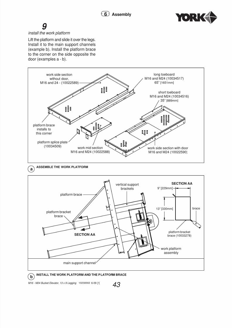
9 install the work platform
Lift the platform and slide it over the legs.Install it to the main support channels(example b). Install the platform braceto the corner on the side opposite thedoor (examples a - b).
ASSEMBLE THE WORK PLATFORMa
work side section
without door,M16 and 24 - (10022589)
long toeboardM16 and M24 (10034517)
65” [1651mm]
short toeboard
M16 and M24 (10034516)
35” [889mm]
work side section with doorM16 and M24 (10022590)
platform braceinstalls to
this corner
platform splice plate
(10034509) work mid sectionM16 and M24 (10022588)
6 Assembly
INSTALL THE WORK PLATFORM AND THE PLATFORM BRACEb
platform brace
vertical support
brackets
platform bracket
brace
work platform
assembly
main support channel
SECTION AA
13 1/2" [343mm]
9" [229mm]
platform bracketbrace (10033278)
SECTION AA
brace
9” [229mm]
13” [330mm]

7/31/2019 11E-YorkBucketElevatorM16-M24LeggingConstructionManual (1)
http://slidepdf.com/reader/full/11e-yorkbucketelevatorm16-m24leggingconstructionmanual-1 44/84
M16 - M24 Bucket Elevator, 13 x 9 Legging 10230002 6-09 [1]
44
10 add the hand rails & guy wire bracket
Install posts and hand rails to theplatform. Securely tighten allplatform bolts! Fasten the guy wirebracket approximately 8” [203mm] below the work platform channels(example a).
ASSEMBLE THE M16 AND M24 WORK PLATFORM RAILINGb
work platform
platform rail
33 1/2” [851mm]
(10033175) upright post41 3/4” [1,060mm]
(10033147)
rail
104” [2,642mm]
(10033176)
NOTE: Welding the guy wire bracket tothe leg section will make the connection
more secure at this location!
6 Assembly
INSTALL THE GUY WIRE BRACKETa
guy wire bracket
spacer: M16 - no spacer M24 - 8” [203mm] spacer
3” [76mm] of weld
minimum.Use touch-upfor paintedunits or a zincrich spraypaint forgalvanizedlegs.
see alsopage 58

7/31/2019 11E-YorkBucketElevatorM16-M24LeggingConstructionManual (1)
http://slidepdf.com/reader/full/11e-yorkbucketelevatorm16-m24leggingconstructionmanual-1 45/8445
M16 - M24 Bucket Elevator, 13 x 9 Legging 10230002 6-09 [1]
Distributor Platform
11 distributor platform channels & brkts.
Bolt the distributor platform bracketsand support channels to the legs at apoint that allows easy access to work on
the distributor and/or valving that maybe supplied (example a and example aon the next page).
6 Assembly
BOLT DISTRIBUTOR CHANNELS AND BRACKETS IN PLACE
a
work platform
customer's discretion
platform brace
head assembly
guy wire bracket
distributorplatform
main
support channel
customer’s discretion

7/31/2019 11E-YorkBucketElevatorM16-M24LeggingConstructionManual (1)
http://slidepdf.com/reader/full/11e-yorkbucketelevatorm16-m24leggingconstructionmanual-1 46/84
M16 - M24 Bucket Elevator, 13 x 9 Legging 10230002 6-09 [1]
46
12 build the distributor platform
Put the distributor platform together by joining the parts in the manner shownin example c (the next page) and
examples a - b. Make certain the unitis square and tighten all bolts.
DISTRIBUTOR PLATFORM SUPPORTS DETAILa
main support
channel
up leg
down leg
auxiliary support
channel
auxiliary support
channel
ASSEMBLE THE DISTRIBUTOR PLATFORMb
distributor auxiliarywalkway
M16 and M24(10022593)
platform side toe boardM16 and M24(10034551)32” [813mm]
auxiliary distributorsupport channelM16 and M24(10034524)
main distributor support channelM16 and M24(10022601)
splice plate(10034509)
distributor platform bracket(10033263)
distributor platform side sectionM16 and M24 RH (10022591)M16 and M24 LH (10022592)
NOTE: Components are shown for
a right hand drive setup. Reverse
for a left hand unit.
6 Assembly

7/31/2019 11E-YorkBucketElevatorM16-M24LeggingConstructionManual (1)
http://slidepdf.com/reader/full/11e-yorkbucketelevatorm16-m24leggingconstructionmanual-1 47/84

7/31/2019 11E-YorkBucketElevatorM16-M24LeggingConstructionManual (1)
http://slidepdf.com/reader/full/11e-yorkbucketelevatorm16-m24leggingconstructionmanual-1 48/84
M16 - M24 Bucket Elevator, 13 x 9 Legging 10230002 6-09 [1]
48
13 install posts, rails, and walk surface
Assemble the walkways to the supportchannels on the distributor platform(example c). Assemble posts and rails
to the platform. Tighten all bolts.
NOTE: The corner assembly in
DETAIL b is not typical forthe platform.
DETAIL aa
rail
platform
upright post
rail
DETAIL bb
rail
rail
platformupright post
ASSEMBLE THE DISTRIBUTOR PLATFORM RAILINGc
DETAIL a DETAIL b
rail37 3/4”[959mm]
(10033143)
upright post41 3/4”
[1,060mm]
(10033147)
railM16 and M24 - 90”
[2,286mm]
(10033142)
railM16 and M24 - 51”
[1,295mm]
(10034675)
railM16 and M24 - 63 3/4”
[1,619mm]
(10034676)
rail
M16 and M24 - 28”[711mm]
(10033139)
railM16 and M24 - 89”
[2,261mm]
(10033140)
6 Assembly

7/31/2019 11E-YorkBucketElevatorM16-M24LeggingConstructionManual (1)
http://slidepdf.com/reader/full/11e-yorkbucketelevatorm16-m24leggingconstructionmanual-1 49/84
49 M16 - M24 Bucket Elevator, 13 x 9 Legging 10230002 6-09 [1]
14 correctly install ladder clips and splices
Before installing ladders, note howto correctly install ladder clips andsplices. (examples a - g). Laddersplices are used to join ladder sections.Ladder clips are used to install ladderbrackets and ladder cages to ladders.When installing the ladder be certain tofollow all instructions regarding correctladder bracket spacing and alwayssecurely tighten all bolts!
Ladders
TOP VIEW, LADDER CLIP AND BOLTc
LADDER CLIP AND BOLT,PREASSEMBLED
NOTE how theclip flattens out.
TOP VIEW, LADDER CLIP AND BOLTd
LADDER CLIP AND BOLT,ASSEMBLED
TOP VIEW, LADDER SPLICEb
ladder side rail
ladder splice
(088029)
TOP VIEW, LADDER SPLICE
LADDER CONNECTION ASSEMBLYa
ladder section
ladder splice(088029)
5/16” bin bolt,hex nut & washer
6 Assembly

7/31/2019 11E-YorkBucketElevatorM16-M24LeggingConstructionManual (1)
http://slidepdf.com/reader/full/11e-yorkbucketelevatorm16-m24leggingconstructionmanual-1 50/84
M16 - M24 Bucket Elevator, 13 x 9 Legging 10230002 6-09 [1]
50
NOTE: OSHA Regulation -Subpart D., Section 1910.27 (d) (iv)
states in part: “Cages shall extend
down the ladder to a point not lessthan seven (7’ feet [2135 mm]) nor
more than eight (8’ feet [2438 mm])above the base of the ladder.”
LEG CASING LADDER BRACKET ASSEMBLYe
see
examples
c and d
on theprevious page
Securely tighten all bolts!
FLANGE LADDER BRACKET ASSEMBLY TOP VIEWf
seeexamples
c and d
on the
previous page
6 Assembly
LADDER WITH CAGEg
ladder cage upright
ladder cage upright
ladder section
see
examples
c and d
on the
previous page

7/31/2019 11E-YorkBucketElevatorM16-M24LeggingConstructionManual (1)
http://slidepdf.com/reader/full/11e-yorkbucketelevatorm16-m24leggingconstructionmanual-1 51/84
51M16 - M24 Bucket Elevator, 13 x 9 Legging 10230002 6-09 [1]
15 install ladders, fl ange ladder brackets
Where ladder brackets must beinstalled on the flanges, use theprovided 3/8” x 1 3/4” bolts to securethe flange and spacer angle together.When adding the ladder bracket,install the included spacer on the endbolt. Align the ladder bracket over thebolts and secure with 3/8” flange nuts.When installing the ladder, place thebracket side plate, install a ladder clipand bolt, then fasten to the ladderbracket using 3/8” x 1” bolts and flangenuts. (see the example below).
LADDER CLIP AND BOLT AND BRACKET SIDE PLATE INSTALLATIONb
ladder clip
and bolt
(088028)
3/8” x 1” bin boltand flange nut
flange bracket
side plate(10035561)
6 Assembly
a
3/8” x 1 3/4” grade 8 binbolt with seal washer
(018982)and flange nut (90005027)
spacer (10035666)
flange bracket complete
assembly (10022907)spacer
angle
ladder bracket universal (small)(10035560)

7/31/2019 11E-YorkBucketElevatorM16-M24LeggingConstructionManual (1)
http://slidepdf.com/reader/full/11e-yorkbucketelevatorm16-m24leggingconstructionmanual-1 52/84
M16 - M24 Bucket Elevator, 13 x 9 Legging 10230002 6-09 [1]
52
16 leg casing ladder bracket installation
Continue installing the ladders tothe elevator legs (examples a - bon the previous page, example b on
the next page, and the examples onpage 54). Follow all ladder instructionsand examples given on pages 49 - 55when installing ladders. Your elevatorshould come with at least (1) ladderbracket assembly per every 10’ [3048mm] of ladder. There should also be (1) extraladder bracket for the work platform,and (1) extra for the distributor platformand (1) extra for the complete elevator.Install ladders to each stackable legsection before stacking your elevator.
(See page 59 to view an exampleof a stackable leg section.) See thestacking drawing sent with yourorder acknowledgement as individualelevators are stacked differently!
6 Assembly
LEG CASING LADDER BRACKET INSTALLATIONa
leg
ladder section
leg casing
ladder bracket

7/31/2019 11E-YorkBucketElevatorM16-M24LeggingConstructionManual (1)
http://slidepdf.com/reader/full/11e-yorkbucketelevatorm16-m24leggingconstructionmanual-1 53/8453
M16 - M24 Bucket Elevator, 13 x 9 Legging 10230002 6-09 [1]
LEG CASING LADDER BRACKET ASSEMBLY TOP VIEWb
flat washer(90010020)
ladder bracket back piece
(10033274)
3/8” lock washer(90010021)
ladder bracket
side piece
(10033271)
ladder bracketoutside
(080022)
ladder rung
ladder clip assembly
3/8” hex nut
(90005021)
ladderbracket
outside
3/8” x 1 1/2” hex bolt
(018981)
Complete Assembly
(10022191)
6 Assembly

7/31/2019 11E-YorkBucketElevatorM16-M24LeggingConstructionManual (1)
http://slidepdf.com/reader/full/11e-yorkbucketelevatorm16-m24leggingconstructionmanual-1 54/84
M16 - M24 Bucket Elevator, 13 x 9 Legging 10230002 6-09 [1]
54
flange bracketflange bracket
flange bracket
flange bracket
leg casingbracket
leg casing bracket
flange bracket
flange bracket
leg casing
bracket
flange bracket
leg casingbracket
4’ [1219mm]
ladderextension
platform
assembly
6 Assembly
WARNING! Install leg casingbrackets where necessary to secure
ladder for safe ascension anddescension, or at customer’s discretion
where desired.

7/31/2019 11E-YorkBucketElevatorM16-M24LeggingConstructionManual (1)
http://slidepdf.com/reader/full/11e-yorkbucketelevatorm16-m24leggingconstructionmanual-1 55/84
55 M16 - M24 Bucket Elevator, 13 x 9 Legging 10230002 6-09 [1]
STANDARD, DOUBLE, AND FLARED D-RINGSa
double d-ring
used to join cage sections together
standard d-ring
flared d-ring
TYPICAL CAGE ASSEMBLYb
10’ [3048mm]
cage
10’ [3048mm]
flared cage
17 install ladder cages
Assemble the ladder cages as shownin the examples on this page andpages 49 - 50.
6 Assembly

7/31/2019 11E-YorkBucketElevatorM16-M24LeggingConstructionManual (1)
http://slidepdf.com/reader/full/11e-yorkbucketelevatorm16-m24leggingconstructionmanual-1 56/84
M16 - M24 Bucket Elevator, 13 x 9 Legging 10230002 6-09 [1]
56
18 install the rest platform surface Assemble the basic rest platform on aflat surface (examples a and b). Make
INSTALL BRACKETS AND CHANNELS TO THE REST PLATFORMa
rest platform channel bracket
(10022187)
rest platform walk assemblyM16 and M24 (10022604)
rest platform support channel(10034548)
support channel bracket(10033199)
Rest Platform
certain the unit is square and tightenall bolts. Install the rest platform(s) to
the legs at predesignated locations foreach leg it installs to (example b). Seepage 23.
6 Assembly
PLATFORM DIMENSIONSb
legs
rest platform
support channel
32” [813mm] = M2424” [610mm] = M16
38” [965mm]
64 1/2” [1,638mm]

7/31/2019 11E-YorkBucketElevatorM16-M24LeggingConstructionManual (1)
http://slidepdf.com/reader/full/11e-yorkbucketelevatorm16-m24leggingconstructionmanual-1 57/8457
M16 - M24 Bucket Elevator, 13 x 9 Legging 10230002 6-09 [1]
19 install rest platform handrails & posts
Install the posts and hand rails to theplatform (example a). Securely tightenall bolts on the platform.
ASSEMBLE THE REST PLATFORM RAILINGa
short platform rail(10033143)
37 7/8” [962mm]
outside long
platform railM16 and M24
(10033186)66” [1676mm]
platform upright
post(10033147)
41 3/4” [1060mm]
platform walkassembly
M16 and M24
(10022604)
leg side long platform rail,
M16 and M24 (10034681)61 1/2” [1,562mm]
6 Assembly

7/31/2019 11E-YorkBucketElevatorM16-M24LeggingConstructionManual (1)
http://slidepdf.com/reader/full/11e-yorkbucketelevatorm16-m24leggingconstructionmanual-1 58/84
M16 - M24 Bucket Elevator, 13 x 9 Legging 10230002 6-09 [1]
58
20 make stackable leg sections
Follow the stacking drawing for yourelevator (the plans sent with the orderacknowledgement). Refer to thisstacking plan and start connectingleg to leg (example a) to build thepre-planned stackable leg sections.
Note: Read this note before lifting sections as shown on the next page. Mostcontractors use this procedure: Lift the uppermost assembly section by looping anylon choker or other strapping device around the shaft. Wire or install the headcover to the work platform when lifting the uppermost assembly section. This willeliminate a separate lifting of the head cover.
TYPICAL, ALL HOLESb
3/8” bolt
3/8” nut
NOTE: Use a bead of caulking at
all flange connections including theleg-to-boot connection.
6 Assembly
Stackable Leg Sections
CONNECT LEG SECTIONSa
see
example b
legsections
spacer angle
M16 (10030116)M24 (10330160)
TYPICAL GUY WIRE BRACKET INSTALLATIONc
guy wire bracket
3” [76mm] of weldminimum. Usetouch-up painton painted unitsor a zinc richspray paint forgalvanized legs.See page 44.
spacer: M16 - no spacer M24 - 8” [203mm] spacer
(10030560)

7/31/2019 11E-YorkBucketElevatorM16-M24LeggingConstructionManual (1)
http://slidepdf.com/reader/full/11e-yorkbucketelevatorm16-m24leggingconstructionmanual-1 59/8459
M16 - M24 Bucket Elevator, 13 x 9 Legging 10230002 6-09 [1]
Note: Welding the guy wire bracket to the leg section will make theconnection more secure at this location.
ComponentElevator Model
M16 M24
Head 460 [209] 615 [279]
Drive with Motor 160 [73] 280 [127]
Work Platform 718 [326] 718 [326]
Distributor Platform 559 [000] 559 [000]
10’ [3048mm] Leg Section
300 [137] 300 [137]
10’ [3048mm] Ladder 40 [18] 40 [18]
10’ [3048mm] Cage 40 [18] 40 [18]
Rest Stop 198 [90] 198 [90]
Guy Cable/Bracket/10’ [3048mm]
70 [32] 70 [32]
Miscellaneous 250 [113] 300 [113]
Approx. Hoisting Weight - lb. [kg]
21
install guy wire brackets Follow the stacking drawing for yourelevator and pages 25 - 27 to placeguy wire brackets at preplanned legconnections (example c, the previouspage). Remember: When completed,the elevator should have (1) guy wirebracket per every 20’ [6096mm] (or less)of leg section.
22 install stackable leg sections Follow the stacking drawing sent withthe order acknowledgement. Stack thestackable leg sections which are nowassembled. Set (1) on another until thecomplete basic elevator assembly is(1) unit (example a). See the importantinstructions on the next page that gowith this step.
NOTE: If elevator sits in a pit, guying startsapproximately 20’ [6096mm] above grade.
6 Assembly
STACKING THE ELEVATOR IN SECTIONSa
wire on hood
an upper
stackable leg
section
an
intermediate
stackable leg
section
boot
30’ [9,144mm] or less
30’ [9,144mm] or less

7/31/2019 11E-YorkBucketElevatorM16-M24LeggingConstructionManual (1)
http://slidepdf.com/reader/full/11e-yorkbucketelevatorm16-m24leggingconstructionmanual-1 60/84
M16 - M24 Bucket Elevator, 13 x 9 Legging 10230002 6-09 [1]
60
Setting and Guying
Instructions
1 If the boot is located in a pit, the leg in the pit must also be laterally (horizontally) braced.The leg may be braced near ground level (work floor) to obtain maximum head clearance onthe first set of cables above the ground level.
2 Before setting the leg on the boot, be certain that the head section is in an exactplumb position to the boot. Use a transit (or transits) to check its position. Use abead of caulking at the flanges and set the leg into position. Bolt the flanges together.
3 Connect each guy cable to its anchor. See page 26. Start connecting the lower setof cables first and progress towards the top. Locate a turnbuckle in each cable at aconvenient distance from the anchor. Extend the turnbuckles as far as possible for lateradjustment. See pages 25 - 27 and 71 - 72 for anchor and cable clamping information.
4 Use (2) transits to keep the leg straight and plumb when tightening the cables. Locate(1) transit in line with (1) row of anchors and about 50’ [15,240mm] further away from theleg than the furthest anchor. This transit will be used for adjusting cables extending tothe right and left of it. Set a second transit 90 degrees from the first transit in line withthe second row of anchors to adjust cables extending in the other (2) directions. Whenplumbing the leg, tension the cables to 600-700 pounds [273-317kg].
5 Tighten (2) opposite cables on the same level together. Keep the leg straight whentightening the cables. This will balance the tension in the (2) cables. Tighten all (4)cables at each level before proceeding upward to the next level of cables.
6 A final recheck on the plumbing is made with a plumb bob. If the leg is not perfectlyplumb, there can be difficulty experienced with the belt not running true. Inserta plumb bob into the up leg section from the head section. Lower the plumb bob pastthe inspection door. Tie the plumb line to a cross board over the top of the head frame.Locate the line so it clears all sides inside the leg. Note the position of the plumb lineat the top end and bottom end.. The distance to the sides of the leg must be the sameat the top and bottom. If it is not the same within 1/2” [13mm], readjust the guy cables.Readjustment of the transits may be helpful to maintain the straightness of the leg.
Note: Either end or the center of a turnbuckle may turn and loosen thecable. (1) method of securing the cable is to lace a short length of cablethrough the ends and center of the turnbuckle and secure the cable with cableclips. This also deters unauthorized persons from loosening the cables.
6 Assembly

7/31/2019 11E-YorkBucketElevatorM16-M24LeggingConstructionManual (1)
http://slidepdf.com/reader/full/11e-yorkbucketelevatorm16-m24leggingconstructionmanual-1 61/8461
M16 - M24 Bucket Elevator, 13 x 9 Legging 10230002 6-09 [1]
6 Assembly
Belt and Buckets
23 install buckets to the belt
Install the buckets to the belt using thepre-punched holes in the belt (see theexamples on this page). Tighten the
nuts so that the head draws influshwith the belt surface.
24 thread assembled belt into elevator
Remove the inspection door cover.(Do not do this if winds exceed 20 mph[32 km/h].) From the top of the elevatorthread a rope down the leg to the pointwhere the inspection door is located.Fasten the rope to the assembled belt.
Using a come-along pull the belt throughthe inspection opening to the top of theleg, wrap it over the head pulley, andthread it down the other leg.
STEEL BUCKET INSTALLATIONa
flat headbolt
flange nut
Note: Let the belt hang over thehead pulley for 24 hours. This willallow gravity to stretch the beltand will provide some initial beltstretch. This will minimize future
belt stretch.
WARNING! After all cables have been tensioned and the leg recheckedfor plumb and straightness, secure the turnbuckles from loosening.
PLASTIC BUCKET INSTALLATIONb
flat headbolt nut
flat washer
lock washer

7/31/2019 11E-YorkBucketElevatorM16-M24LeggingConstructionManual (1)
http://slidepdf.com/reader/full/11e-yorkbucketelevatorm16-m24leggingconstructionmanual-1 62/84
M16 - M24 Bucket Elevator, 13 x 9 Legging 10230002 6-09 [1]
62
25 make the fi nal belt splice
Adjust the boot pulley into its highestposition with the take-up screws. Pullthe belt around the boot pulley andback up to the inspection opening
to make the final belt splice. Beltsplice clamps are shipped with eachelevator. An alternate method is thelap splice as shown in example b.Reinstall the inspection door coverwhen complete.
Belt Splice
6 Assembly
FINAL BELT SPLICEa
10” bar splice(10020149)belt
belt
LAP SPLICEb
belt
5’ [1,524mm]
minimum
WARNING! It is very important that the final belt splice is made squarewith the belt to insure a straight running belt.

7/31/2019 11E-YorkBucketElevatorM16-M24LeggingConstructionManual (1)
http://slidepdf.com/reader/full/11e-yorkbucketelevatorm16-m24leggingconstructionmanual-1 63/8463
M16 - M24 Bucket Elevator, 13 x 9 Legging 10230002 6-09 [1]
26 adjust the belt tension
Belt tension is adjusted by use of thetake-up assemblies at the boot. Tensionthe belt to remove all slack. Lower
the boot pulley 1” [25mm] more if yourbucket elevators is under 60’ [18,288mm] and 2” [50mm] if your elevator is over60’ [18,288mm]. Steering (centering)action is accomplished by adjusting (1)side of the boot tighter than the other.The belt will move to the slack side.The belt must have enough tensionto keep the head pulley from slippingunder a full load condition. Thereshould be no “rattling” when the elevatorruns empty.
27 adjust the discharge baf fl e
The discharge hopper is located inthe head discharge section. It deflectsthe material from the buckets so onlya minimal amount of material returnsdown the leg (called “back legging”).Adjust the hopper so it will clear thebuckets by 1/8” [3mm] (see example
at right). This adjustment should bemade when the splice is located at thedischarge baffle. Install the head frontand back to the head housing usingthe hold-down clips.
ADJUST THE DISCHARGE BAFFLEa
bucket
discharge baffle
cup bolt and nut
back-up-plate
discharge hopper
bucket
belt
1/8” [3mm]
6 Assembly

7/31/2019 11E-YorkBucketElevatorM16-M24LeggingConstructionManual (1)
http://slidepdf.com/reader/full/11e-yorkbucketelevatorm16-m24leggingconstructionmanual-1 64/84
M16 - M24 Bucket Elevator, 13 x 9 Legging 10230002 6-09 [1]
64
The drawing at the left designates the various parts of the indicator that
are supplied for cable control.
1 Install the upper pulley to the pipe on the bottom of the distributor
and tighten the set screws securely.
2 The upper transfer pulley should then be installed to the elevator leg
casing, making certain that the upper pulley is in line with the transfer
pulleys which will make the cable run freely.
3 The latch control transfer pulley is supplied so that the cable thatcontrols the latch cable can run down the side of the leg casing. Toprevent as much drag as possible on the cable, this pulley should
be located so that the cable is at a 45°angle.
4 On taller installations, you may want to use intermediate cable
guides to prevent the cable from whipping around and becomingcaught or tangled. These can be installed where you deem
necessary.
5 Install the indicator wheel so that it can easily be operated from the
work room floor. Install it to the leg using the provided clamps.
6 Locate the foot pedal so that it can be operated at the same time
the number disc is being turned.
7 The amount of cable needed can be determined by taking theheight of the distributor above the work floor times three (x3). When
installing the cable, be certain that it is secured to both the top andbottom pulleys so that it cannot slip. If possible, start at the bottom,
run up through the transfer pulley, wrap the cable twice and secure.A turnbuckle is supplied to splice the cable with and to adjust
tension.
8 Install the cable to the spout latch inside the distributor and run itdown through the pipe, through the latch control cable pulley and
install to the foot pedal.
9 The adhesive-backed numbers can be placed on the number disc,as the spouts moved from opening to opening. Place the numbersso that when vertical, it indicates which spout is located for feeding.
10 For easier operation, ensure that all control cables are not rubbingon flanges or other obstructions.
28 install the wire rope indicator
a
the foot pulley isnormally installed
on the main floorso that the pedaland number disccan be operatedat the same time
distributor
down leg
pipe
upper pulley
transfer pulley
latch control cablepulley (installed tofirst lower section)
latch control cable
turnbuckle
indicator numberwheel completewith pressuresensitive numbersfor installing tonumber disc
Typical Installation Instructions
Wire Rope Indicator
6 Assembly

7/31/2019 11E-YorkBucketElevatorM16-M24LeggingConstructionManual (1)
http://slidepdf.com/reader/full/11e-yorkbucketelevatorm16-m24leggingconstructionmanual-1 65/8465
M16 - M24 Bucket Elevator, 13 x 9 Legging 10230002 6-09 [1]
Drive Packages
6 Assembly
TORQUE ARM MOUNTING BRACKET POSITIONS
A B C D

7/31/2019 11E-YorkBucketElevatorM16-M24LeggingConstructionManual (1)
http://slidepdf.com/reader/full/11e-yorkbucketelevatorm16-m24leggingconstructionmanual-1 66/84
M16 - M24 Bucket Elevator, 13 x 9 Legging 10230002 6-09 [1]
66
6 Assembly
Horsepower and Drive RequirementsDrive
(Class 1)DischargeFt.
1000HP
1500HP
2000HP
2500HP
3000HP
20 2 2 2 2 3
TA1(60)
25 2 2 2 3 3
30 2 2 3 3 5
35 2 2 3 5 5
40 2 3 3 5 5
45 2 3 5 5 5
50 2 3 5 5 7.5
55 2 3 5 5 7.5
60 3 5 5 7.5 7.5
65 3 5 5 7.5 7.5
70 3 5 5 7.5 7.5
75 3 5 7.5 7.5 10
80 3 5 7.5 7.5 10
85 5 5 7.5 10 10
90 5 5 7.5 10 10
95 5 7.5 7.5 10 15
100 5 7.5 7.5 10 15
TA2(100)
105 5 7.5 10 10 15
110 5 7.5 10 10 15
115 5 7.5 10 15 15120 5 7.5 10 15 15
Model 16 Horsepower Requirements

7/31/2019 11E-YorkBucketElevatorM16-M24LeggingConstructionManual (1)
http://slidepdf.com/reader/full/11e-yorkbucketelevatorm16-m24leggingconstructionmanual-1 67/8467
M16 - M24 Bucket Elevator, 13 x 9 Legging 10230002 6-09 [1]
6 Assembly
Horsepower and Drive RequirementsDrive
(Class 1)Discharge
Ft.
2000HP
2500HP
3000HP
3500HP
4000HP
25 3 5 5 5 5
TA1(60)
30 3 5 5 5 5
35 3 5 5 5 5
40 3 5 5 5 7.5
TA2(100)
45 5 5 5 7.5 7.5
50 5 5 7.5 7.5 7.5
55 5 7.5 7.5 7.5 10
60 5 7.5 7.5 7.5 10
65 5 7.5 7.5 10 10
70 7.5 7.5 10 10 10
75 7.5 7.5 10 10 15
TA3(120)
80 7.5 7.5 10 10 1585 7.5 7.5 10 15 15
90 7.5 10 10 15 15
95 7.5 10 10 15 15
100 7.5 10 15 15 15
105 7.5 10 15 15 20
TA4(200)
110 10 10 15 15 20
115 10 15 15 15 20
120 10 15 15 20 20
125 10 15 15 20 20
1301 10 15 15 20 20
1351 10 15 15 20 20
1401 10 15 20 20 25
1451 15 15 20 20 25
1501 15 15 20 20 25
Model 24 Horsepower Requirements

7/31/2019 11E-YorkBucketElevatorM16-M24LeggingConstructionManual (1)
http://slidepdf.com/reader/full/11e-yorkbucketelevatorm16-m24leggingconstructionmanual-1 68/84
M16 - M24 Bucket Elevator, 13 x 9 Legging 10230002 6-09 [1]
68
Truss Kits, 6” - 12” Diameter Downspouts
29 install downspouts and truss kits
Install trusses. Use approximatedimensions shown in these examples.Set spout flat on the ground.
Note: The detail drawings for theexamples below are on page 70.
6 Assembly
40 ft. (above) and 60’ (below) truss kits should be installed with approximate dimensions as shown. Overalldiameter of 24” spider will be 5 feet.
80 ft. (below) truss kits should be installed with approximate dimensions, as shown. Overall diameter of48” spider will be 8 feet and diameter of 24” spider will be 5 feet.
100 ft. (below) truss kits should be installed with approximate dimensions, as shown. Overall diameter of 66”
spider will be 10-1/2 feet. 48” spider will be 8 feet and 24” spider will be 5 feet.
example a
A
1
A
1
A
1
A
1
B
1field weld all endclamps to spout
B
1
field weld all endclamps to spout
B
1
field weld all endclamps to spout
B
1
field weld all endclamps to spout
example b
example c
example d
SI conversions:
ft = [mm]
5’ = [1524mm]8’ = [2438mm]
10 1/2” = [3,200mm]40’ = [12,192mm]
60’ = [18,288mm]
80’ = [24,384mm]
100’ = [30,480mm]
inches = [mm]
24” = [610mm]
48” = [1,219mm]
[1,524mm]
[4,572mm] [4,572mm]
[1,524mm]
[ 1 , 5
2 4 m m ]
[4,572mm] [4,572mm][6,096mm]
[ 1 , 5
2 4 m m ]
[6,096mm] [6,096mm][4,572mm] [4,572mm]
[ 1 , 5
2 4 m m ]
[ 1 , 5
2 4 m m ]
[6,096mm] [6,096mm][4,572mm] [4,572mm]
[3,048mm] [3,048mm]
[1,524mm] [1,524mm]

7/31/2019 11E-YorkBucketElevatorM16-M24LeggingConstructionManual (1)
http://slidepdf.com/reader/full/11e-yorkbucketelevatorm16-m24leggingconstructionmanual-1 69/84

7/31/2019 11E-YorkBucketElevatorM16-M24LeggingConstructionManual (1)
http://slidepdf.com/reader/full/11e-yorkbucketelevatorm16-m24leggingconstructionmanual-1 70/84
M16 - M24 Bucket Elevator, 13 x 9 Legging 10230002 6-09 [1]
70
31install the cables
Install the cables to the arm assemblies.Tighten the cables (see examples A/1,B/1, and pages 71 - 72. Install thespouts into place. Be certain to installthe wire rope clips following theinstructions in this manual!
Important Note: Bottom cable(s)should be taut enough to keep the downspout
straight. Top cables should be drawn up snug!
Truss Cables
DETAIL OF PIPE CLAMPA
1
3/8” x 1 1/4” bolt (900-00032)
and nut (900-05021)
1/2” pipe clamp welded
assembly (2)3/8” cable clip (900-31015)
3/8” cable thimble (900-31030)
downspout
DETAIL OF PIPE CLAMPB
1
downspout
3/8” cable clamp (900-31015)
3/8” cable thimble
(900-31030)
3/8” x 1 1/4” bolt (900-00032)
and nut (900-05021)
1/2 pipe clamp
welded assembly
1/2” [13mm] x 6” [152mm] turnbuckle
(use on end of spout with easiest
access from bin top, serviceplatform, ground, etc. so turnbuckle
can be adjusted.) (900-31023)
6 Assembly

7/31/2019 11E-YorkBucketElevatorM16-M24LeggingConstructionManual (1)
http://slidepdf.com/reader/full/11e-yorkbucketelevatorm16-m24leggingconstructionmanual-1 71/8471
M16 - M24 Bucket Elevator, 13 x 9 Legging 10230002 6-09 [1]
Wire Rope Termination
Wire Rope Clip Installation 1 TURN BACK the specified amount of rope from the thimble. Apply the firstclip approximately (1) base width from the dead end of the wire rope (Install theU-bolt onto the dead end of the wire rope, and install the saddle onto the liveend of the wire rope.
2 APPLY THE NEXT CLIP as near the loop or thimble as possible. Turn on nutsfirm but do not tighten.
3 SPACE ADDITIONAL CLIPS, if required, between the first (2). Turn on nuts- take up rope slack - tighten all nuts evenly on all clips to recommended torque.
NOTICE!
4 APPLY THE INTITIAL LOAD and retighten nuts to the recommended torque.Rope will stretch and shrink in diameter when loads are applied. Inspect regularlyand retighten.
Note: A wire rope termination made in accordance with the instructions, and using the
number of clips shown has an approximate 80% effi
ciency rating. This rating is based on thecatalog breaking strength of the wire rope.
6 Assembly
WARNING! Failure to make wire rope terminations in accordance with the instructionsor failure to regularly check and retighten to recommended torque will cause a reduction in the
wire rope efficiency rating noted on this page!
WARNING!
• Failure to read, understand, and follow all Wire Rope Terminationinstructions on this page and the next page may cause death or serious injury!
• Read and understand these instructions before using wire rope clips.
• Match the same size clip to the same size wire rope.
• Do not mismatch wire rope clips with wire rope clips made by other manufacturers.
• Prepare wire rope end termination only as instructed.

7/31/2019 11E-YorkBucketElevatorM16-M24LeggingConstructionManual (1)
http://slidepdf.com/reader/full/11e-yorkbucketelevatorm16-m24leggingconstructionmanual-1 72/84
M16 - M24 Bucket Elevator, 13 x 9 Legging 10230002 6-09 [1]
72
6 Assembly
WIRE ROPE TERMINATION; WIRE ROPE CLIP INSTALLATIONa
7” [178mm]
turnbackdead end
live end
Right Way for maximum
rope strength
Wrong Way! clips staggered
Wrong Way!clips reversed
clip facingwrong way!
clip facing
wrong way!
clip facing
wrong way!
install firstinstall second
cable stop sleeve(not provided by Mfs/York/Stormor)
base width

7/31/2019 11E-YorkBucketElevatorM16-M24LeggingConstructionManual (1)
http://slidepdf.com/reader/full/11e-yorkbucketelevatorm16-m24leggingconstructionmanual-1 73/8473
M16 - M24 Bucket Elevator, 13 x 9 Legging 10230002 6-09 [1]
Belt Tension
32 adjust the belts
Tighten the (4) jackscrews hex nutsat the motor base to adjust the V-belt.Maintain shaft alignment. Adjustthe motor base equally at all (4)
jackscrews. Tighten the V-belts tothe correct tension. When the V-belttension is correct, tighten the topon the jackscrews to lock the motorbase in position. Belt deflection is1/64” [0.4mm] per 1” [25.4mm] of span.
CrossSection Smallest SheaveDiameter Range MotorRPM
Belt Deflection Force
Normal New
3VX2.65 - 3.65 1750 4.2 6.2
4.12 - 6.90 1750 5.3 7.9
5VX4.4 - 6.7 1750 8.8 13.2
7.1 - 10.9 1750 13.7 20.1
Drive Belt Deflection Force
6 Assembly
BELT INSTALLATION AND TENSIONa
Belt deflection is 1/64” [0.4mm] per inch ofspan at proper belt tension!
span
belt deflection
force

7/31/2019 11E-YorkBucketElevatorM16-M24LeggingConstructionManual (1)
http://slidepdf.com/reader/full/11e-yorkbucketelevatorm16-m24leggingconstructionmanual-1 74/84
M16 - M24 Bucket Elevator, 13 x 9 Legging 10230002 6-09 [1]
74
7 Assembly
7 Start-Up and Operation7
2. Completion of Flow SystemTo complete an elevator system, otherconnections must be made to the leg.These will need to be completed before
placing the leg into service.
3. Operating the ElevatorSince the elevator has been previouslyoperated without material, it may now betested under load. It is suggested that theflow systems be checked next. Allow only a
small amount of grain to enter the elevatorwhen it is running. Check that the materialcan flow through the system, connections,valves, distributors, etc. After all flow paths
have been checked, the elevator may beloaded to capacity.
4. Check the Elevator for:
a. Back legging (grain returning downthe leg).
b. Head pulley slippage.
c. Proper cup filling.
d. Electrical current draw on the motor.
5. An inspection of the elevatoris recommended after the first8-10 hours of operation.Inspect each of the following:
a. Check all bolts holding the cups tothe belt for tightness.
b. Make certain the belt is running
in the center of the leg past theinspection station.
c. Inspect motor drive for loosenessof pulleys, sprockets, belts, chains ortorque arm.
d. Check for oil leakage or overheatingof the gear reducer.
e. Head pulley hub bolts & set screws.
1. Start Up InspectionBefore operating the elevator, check allareas for SAFETY and machine damagewhich could happen during construction.
a. Has the leg been correctly plumbed,guy cables tensioned, and cables
secured from loosening?
b. Check all set screws in drivesheaves, head and boot pulleys, shaftbearings to make certain they are tight.Follow the torque recommendations ofthe manufacturer(s).
c. Check lubrication of all bearings and
gear reducer.
d. Operate the elevator empty underpower for a period of time. Be certaincups are traveling in the right direction.Be certain the belt is running on center
over the head and boot pulleys. Keeppersonnel away from moving parts.
e. Install the hood, motor driveshields, inspection section screen,door, all covers/guards, and theboot clean-out doors.
f. Review the possibility of vehicle
damage to leg or guy cables.
g. Children and unauthorizedpersons should not have access tothe electric controls or the climbingladder.
h. Are pits designed to preventpersonal injury?
i. Has the electrical equipment been
installed to meet safety codes? Thisincludes explosion proof equipmentwhere used.
NOTE: Your drive belt must be
properly tensioned. See page 73.

7/31/2019 11E-YorkBucketElevatorM16-M24LeggingConstructionManual (1)
http://slidepdf.com/reader/full/11e-yorkbucketelevatorm16-m24leggingconstructionmanual-1 75/8475
M16 - M24 Bucket Elevator, 13 x 9 Legging 10230002 6-09 [1]
back legging (materialfalling down the down leg)
see also “material backlegging” undertroubleshooting, “cups not filling”
belt too loose tighten or shorten belt when needed
head shaft speed not correct correct sheaves, check motor speeds (drivescalculated on motor speeds of 1,750 RPM
damaged cups replace or straighten / find out the cause for damage
spouting too flat angle to be 45°or steeper for dry material, wetmaterial requires steeper angles
overfeeding check conveyor output / make adjustments at inlet
air locked vent may be needed at the boot or in the head
boot pulley out of adjustment move take up rods to center pulley
conveying light material replace the buckets with perforated buckets
wrong style cup consult MFS/YORK/STORMOR for proper cup
belt excessive slipping,burning, or melting
belt slipping or worn head pulley the belt is loose / tighten it
lagging worn off head pulley / replace lagging
belt is running to (1) side(belt will not track)
belt on boot pulley not running oncenter
belt too loose to give guidance / tighten or shortenthe belt as needed
boot pulley not level / re-check and align pulley
material build-up on boot pulley / clean pulley
belt on head pulley not running oncenter
leg out of plumb / re-check and plumb legs
belt on head pulley not running oncenter
leg out of plumb / re-check and plumb legs
head pulley not level / re-check andalign pulley
belt loose and slipping / tighten or shorten the beltas needed
cups not filling evenly / check and adjust intake
belt splice crooked or slipped / straighten andtighten splice
legging bent due to stress / damage repair or replace bent section
legging on pulley worn replace with new lagging kit
bearings on head uneven shim lower side until belt centers. Or, move (1) headbearing forward or backward within bearing slots
head pulley has no crown replace pulley
bearing worn defective bearing at head or boot / needs replacement
boot pul ley out of adjustment move take up rods to center the pulley
Trouble Problem Cause / Solution
Troubleshooting

7/31/2019 11E-YorkBucketElevatorM16-M24LeggingConstructionManual (1)
http://slidepdf.com/reader/full/11e-yorkbucketelevatorm16-m24leggingconstructionmanual-1 76/84
M16 - M24 Bucket Elevator, 13 x 9 Legging 10230002 6-09 [1]
76
TroubleShooting
Trouble Problem Cause / Solution
belt loose tighten belt adjust the boot pulley
redo the splice or remove a section of belt
boot pulley build-up excessive powder or sticky material slatted boot pulley required
cups damaged belt loose check boot tension or replace belt
leg bowed and catching re-plumb
obstruction within leg repair or remove
cups too large for casing replace with proper size cups
belt not running smooth may require a different style splice
cups not filling orreduced rated capacity
under feeding check conveyor output
cups running above inlet or improper hopperinstallation / adjust inlet hopper; see page 35.
plugging / check for and remove any inlet plugging
material back-legging the down leg discharge spouting too small or plugged / check for and remove any spouting plugging
incorrect belt speed / adjust speed
incorrect baffle adjustment / adjust it; see page 63.
improper cup design / call MFS/YORK/STORMOR
inlet opening too small increase opening
incorrect belt speed wrong drive sheaves / obtain correct sheaves
incorrect motor speed / adjust speed
incorrect reducer ratio / change ratio
head pulley slipping
drive belt slipping
cups short on volume cups caked full of material (wet or powder type) / material too wet
improper cup size / type material
boot pulley high lower pulley in boot to insure full loading of cups
air lock either vent the bin or the bucket elevator
spouting too small or flat check instructions for sizing
belt loose see troubleshooting, belt loose
obstruction in boot or head remove obstruction and replace damaged cups
cups caked or bent visually inspect, clean or replace damaged cups
cups overfilling overloading elevator inlet feed exceeding capacity of leg / adjust feed
belt speed too slow / adjust speed
belt slipping on head pulley / tighten belt
improper cups / obtain proper cups

7/31/2019 11E-YorkBucketElevatorM16-M24LeggingConstructionManual (1)
http://slidepdf.com/reader/full/11e-yorkbucketelevatorm16-m24leggingconstructionmanual-1 77/8477
M16 - M24 Bucket Elevator, 13 x 9 Legging 10230002 6-09 [1]
TroubleShooting
motor cannot start belt backstop reversed backstop installed wrong / reinstall correctly
motor rotation reversed wired wrong / wire correctly
boot filled with material material not shut off when leg was stopped
damaged reducer broken gears or bearings / replace them
cup caught in leg loose cup or belt
motor starter kicking out
motor overloaded leg being overloaded / adjust load
line voltage low
wrong drive sheaves
motor too small current draw excessive
starter not sized to motor heaters wrong size
motor / starter device defective fix or replace
noise and vibration excessive
cups hitting obstruction in leg
bent or damaged cups / see troubleshooting, bentcups
belt loose / tighten the belt
cups striking base of boot / adjust boot pulley andtighten belt / see troubleshooting, belt loose
excessive belt speed / adjust speed
motor drive noise failed bearings in motor, head shaft or boot shaft / replace as needed
failed bearings in gears or reducers / replace as
neededlow oil level in reducer / add oil
cups not filling evenly / check and adjust intake
belt splice crooked or slipped / straighten and tightensplice
legging bent due to stress / damage repair or replace bent section
lagging on pulley worn replace with new lagging kit
bearings on head uneven shim lower side until belt centers or move (1) headbearing forward or backward within bearing slots
head pulley has no crown replace pulley
bearing worn defective head or boot bearing / needs replacement
boot pul ley out of adjustment move take up rods to center the pulley
reducer overheating low or overfilled gear lubricant not filled according to manufacturers instructions / refill
wrong grade or weight of lubricant see manufacturers instructions and replace
reducer overloaded wrong size reducer / obtain proper size
reducer failing worn gears or failed bearings
Trouble Problem Cause / Solution

7/31/2019 11E-YorkBucketElevatorM16-M24LeggingConstructionManual (1)
http://slidepdf.com/reader/full/11e-yorkbucketelevatorm16-m24leggingconstructionmanual-1 78/84
M16 - M24 Bucket Elevator, 13 x 9 Legging 10230002 6-09 [1]
78
Index
Numbers
300 bushel pit 16
4 basic safety rules 12
500 bushel pit 17
A
accessories 8
airborn dust 10
air system 10
anchor bolts 34
anchors 25, 60
approximate hoisting weights 59
assembly 8, 34
auxiliary distributor support channel 46
auxiliary support channel 46
B
back-up-plate 63
back legging 74
bag filter 10
bar splice 62
be alert 2
bearings 7, 11, 74
belt (elevator belt) 7, 12, 31, 33, 61, 63, 74
belt alignment 7
belt alignment sensors 11
belt and buckets 61
belts (drive belts) 7, 12, 36, 73, 74
belt splice 63
belt tension 63, 73
bolted joints 38
bolted legs 38
boot 22, 24, 33, 34, 59
boot clean-out doors 74
boot footing and pit 24
boot footing loads 24
boot pulley 24, 62, 74
boot shaft 11
bracing 25
buckets 33, 61, 63
buildings 25
C
cable anchor locations 26, 27
cable clips 7, 25, 70, 71
cable control 64
cable loads 25
cables 61
cage 50
caulking 60
chains 12, 74
check delivery 31
choked leg 11
clean-out door 24
cleaners 24
codes 74
construction personnel 2
contents 4
control the dust 10
control the ignition source 11
conveyors 10, 12
covers 12, 74
crane 33
cup bolt and nut 63
cups 7, 31, 74
cutting 11

7/31/2019 11E-YorkBucketElevatorM16-M24LeggingConstructionManual (1)
http://slidepdf.com/reader/full/11e-yorkbucketelevatorm16-m24leggingconstructionmanual-1 79/8479
M16 - M24 Bucket Elevator, 13 x 9 Legging 10230002 6-09 [1]
Index
D
door 74
d-rings 55
decelerators 10
discharge baffle 63
discharge hopper 35
distributor 30, 45, 64
distributor auxiliary walkway 46
distributor dimensions 30
distributor platform 23, 45, 46, 48, 52
distributor platform brackets 45, 46
distributor platform dimensions 47
distributors 24
double d-ring 55
down leg side 24
downspouts 68
drain 24
drive assembly 36, 74
drive belt deflection force 73
drive belts 7, 12, 36, 73, 74
drive components 33
driveways 24
E
edible mineral oil 10
electrical equipment 74
electrical wiring 11
electric controls 74
elevated anchors 25
elevator drive packages 65
elevator leg casing 64
elevator location 24
elevator operation 74
elevator pits 24, 25, 59, 74
equipment failures 13
explosion 10
explosion proofing 74
explosion proof lights 11
explosion venting 11
explosion vents 11, 74
F
farm machinery 25
final belt splice 62
first legs 39
fixed ladders 9
flange bracket side plate 51
flange ladder brackets 50, 51, 54
flared d-ring 55
flared inlet hopper 35
flared ladder cages 55
flow system 74
follow a proper lock-out procedure 13
footing loads 24
foot pedal 64
free flowing materials 24
G
gear reducer 74
general assembly instructions 33
general safety statement 3, 8
grain dust explosion myths 11
grain dust explosions 10
grates 12
grease 7
ground conditions 25
guard fences 25
guard rails 9
guards 12, 36, 74
guy cables 7, 24, 25, 60, 74
guy cables and anchors 25
guy clearance 25
guy wire brackets 25, 33, 44, 45, 58, 59

7/31/2019 11E-YorkBucketElevatorM16-M24LeggingConstructionManual (1)
http://slidepdf.com/reader/full/11e-yorkbucketelevatorm16-m24leggingconstructionmanual-1 80/84
M16 - M24 Bucket Elevator, 13 x 9 Legging 10230002 6-09 [1]
80
Index
H
handrails 9, 44
hardware 32
hazardous areas 11
hazards 3, 8, 10, 24
head 22, 23, 24, 35, 39, 40, 45, 58, 63, 74
head cover 74
head housing 63
head pulley 7, 11, 61, 63, 74
head pulley hub bolts 74
head section 25
heat detectors 11
high winds 24
hold-down clips 63
hood 74
hood back 21, 35
hood front 21, 35
humidity 11
I
indicator wheel 64
inlet hoppers 35
inspection 7, 8, 74
inspection door 61
inspection door cover 61
inspection section screen 74
installation 24
interlock switches 12
intermediate sections 22
J jackscrews 73
K
keys 13
L
ladder and platform arrangement 23
ladder brackets 40, 49
ladder cages 9, 50, 55
ladder clip and bolt 49, 51
ladder clips 49
ladders 23, 24, 33, 49, 74
ladder section 50
ladder side rail 49
ladder splices 49
lagging 11
latch control transfer pulley 64
leg casing ladder brackets 50, 52, 53, 54
leg connections 59
leg section flanges 25
leg sections 31, 33, 39, 44, 58, 59
legs position 38
lights 11
limit switches 11
lock-out 13
lock-out procedure 12
lock form joints 38
locks 13
long toeboard 43
lubrication 7, 11, 74
M
machinery clips 34
magnets 11
main bearing angle 39, 40
main power source 13
main support channels 40, 41, 46
maintenance 7
material handling equipment 9
mineral oil 10
model specifications 20
motion sensors 11

7/31/2019 11E-YorkBucketElevatorM16-M24LeggingConstructionManual (1)
http://slidepdf.com/reader/full/11e-yorkbucketelevatorm16-m24leggingconstructionmanual-1 81/8481
M16 - M24 Bucket Elevator, 13 x 9 Legging 10230002 6-09 [1]
Index
motor 36, 74
motor base 73
motor drive shields 74
motor mount 39, 40
N
no smoking 11
nylon choker 58
O
occupational safety and health act of 1970 9
oil changes 7
oil level inspection 7
operating safety 12
operation 8, 9, 24, 74
operator’s manuals 3
operator qualifications 9
operators 8
OSHA 9, 50
outdoor installations 24
outlets 11
outside bag filter 10
P
parts identification 21
personnel 9
pit drawings 16
pits 24, 25, 59, 74
platform brace 43
platform bracket brace 43
platforms 9, 23
platform side toe board 46
platform splice plate 43
platform support bracket 40, 41
platform upright post 48
power 13
power machinery 9
pre-assembly 24
precautions 3, 8
preface 3
proper personnel 9
pulley hub bolts 7
pulleys 74
R
reaction loads 24
reducers 36, 74
rest platform 56, 58
rest platform channel bracket 56
rest platform handrails and posts 57
rest platform support channel 56
rest stops 23
right hand drive 23

7/31/2019 11E-YorkBucketElevatorM16-M24LeggingConstructionManual (1)
http://slidepdf.com/reader/full/11e-yorkbucketelevatorm16-m24leggingconstructionmanual-1 82/84
M16 - M24 Bucket Elevator, 13 x 9 Legging 10230002 6-09 [1]
82
Index
S
safety 2, 3, 8, 9, 10, 11, 12, 13, 14, 24
safety cages 33
safety questions or concerns 13
seals 7
secondary safety devices 12
see the packing list 31
set screws 7, 74
setting and guying 60
sheaves 36
shims 34
short toeboard 43
shut down 13
soil conditions 25
specifications 18
spider arm assembly 69
splice plate 46
spouting 7, 24, 33, 69
spouting accessories 28
sprockets 74
square and round flanges 30
stackable leg sections 52, 58, 59
stacking drawing / plan 22, 52, 58, 59
stacking exception 22
stacking styles 22
stairways 9
standard d-ring 55
standard inlet hopper 35
start-up 7, 74
start assembly 34
structural capacity 24
structural engineer 2, 24, 25
sump pump 24
support bracket 40
support channels 45, 48
switches 12
T
temporary splice 33
torque arm 74
torque arm mounting bracket positions 65
transfer pulleys 64
transit 60
troubleshooting 75, 76, 77
trucks 25
truss cables 70
truss kits 68, 69
turnbuckles 7, 60, 61, 64
typical elevator anchor 26
typical spider arm 69
U
up leg side 24
upper pulley 64
upper transfer pulley 64
V
v-belts 7, 12, 36, 73, 74
valving 45
vents 11
vertical boot stiffener 34
vertical channels 40
vertical support brackets 40
vertical support channels 43

7/31/2019 11E-YorkBucketElevatorM16-M24LeggingConstructionManual (1)
http://slidepdf.com/reader/full/11e-yorkbucketelevatorm16-m24leggingconstructionmanual-1 83/8483
M16 - M24 Bucket Elevator, 13 x 9 Legging 10230002 6-09 [1]
Recent Significant Manual Changes:
8-08 [1] Revision Changes
1 Model M30 13x9 information was removed throughout.
2 More SI units were added at various locations throughout the manual.
3 Numerous other changes were made throughout the entire manual.
3-09 [1] Revision Changes
1 Pages 4, 5, 36, 57, 58, 59, 69, 74, 75, 76, and 77. Text corrections were made.
2 Page 47. A couple drawing corrections were made.
3 Pages 78 - 82. The index was regenerated. 4 Changes were made throughout the manual to aide in reducing the pdf file size.
5 Other minor changes were made throughout this manual.
6-09 [1] Revision Changes
1 Page 15. A warning decal replacement was made.
2 Pages 16 and 17. A couple drawing corrections were made.
3 Page 32. The bolt torques were updated.
4 Page 64. A type correction was made.
5 Pages 66 and 67. The drive packages information was changed.
6 Page 69. Improvements were made to the instructions on this page.
7 Page 70. Some changes were made to reduce the pdf file size.
Index
W
warning decals 14
warranty 6
welding 11, 44, 59
whole grains 24
wind/weather 2, 24, 61
wind loads 69
wire rope clip installation 71
wire rope clips 7, 25, 70, 71
wire rope indicator 64
wire rope termination 71
work area 8, 9
work area safety statement 8
work hazards 8
work mid section 43
work platform 23, 33, 40, 42, 43, 44, 45, 52
work platform channels 44
work side section with door 43
Z
zerks 7

7/31/2019 11E-YorkBucketElevatorM16-M24LeggingConstructionManual (1)
http://slidepdf.com/reader/full/11e-yorkbucketelevatorm16-m24leggingconstructionmanual-1 84/84
www.globalindinc.comfor information on other Global Industries products see:
GLOBAL INDUSTRIES, INC.


![Ch 1 Making Econ Dcsn 11e[1]](https://img.pdfslide.tips/doc/110x75/55cf94e9550346f57ba54042/ch-1-making-econ-dcsn-11e1.jpg)