Embed Size (px)
Citation preview
Pilot
TNC 426B
TNC 430
11/99
NC Software
280 474-xx
280 475-xx

3
Co
nte
nts
The Pilot
�������������������� ����� � ���������������������������������������� ������� �����!���"�������������#����$����������������� ����� ����������� %�����������������&���'��(���!������������)�!!��������!��������������*
+ ,#������������� ����� + ��������!����!���!�+ ������!����������+ ���!�����������
����������-�!�����������������.�!������������������������������������*
������������
/��� *��� ����������������������������0
������������������������!������-�����������-��������������!�-��!���������������������������0
����������&���'��(���!�)���������)�!!��������������!������������������������������
���������������������.�!������!������������)����������!!�)� ����)������-���*
Cont ro l NC Software Number
�������%������� �1 ��2��33�������4%������� 4 �1 ��25�33
������������ ��
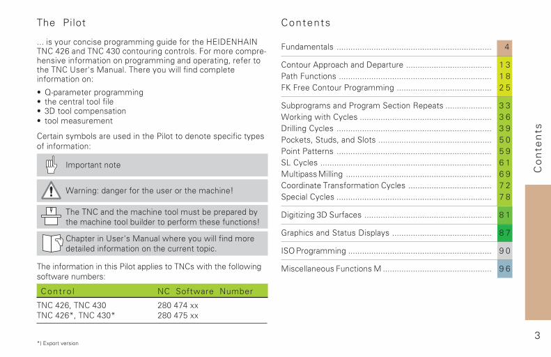
Contents
"�������!� ������������������������������������������������������������������� 4
��������������������������� ������������������������������������� 1 3.����"����� ������������������������������������������������������������������ 1 8"6�"�����������.�� ����� ����������������������������������������� 2 5
7�-��� ��������.�� ����7�����8������ �������������������� 3 3/��9� �)������!�� ��������������������������������������������������������� 3 6���!!� ���!�� ������������������������������������������������������������������� 3 9.�9���%�7����%����7!��� ������������������������������������������������� 5 0.����.������ ������������������������������������������������������������������� 5 97:���!�� �������������������������������������������������������������������������� 6 1(�!�������(�!!� ��������������������������������������������������������������� 6 9�������������������������!�� ������������������������������������ 7 27����!���!�� ������������������������������������������������������������������� 7 8
�� ���;� ����7������ ������������������������������������������������������� 8 1
<����������7����������!��� ������������������������������������������� 8 7
�7=�.�� ����� �������������������������������������������������������������� 9 0
(���!!������"������( ����������������������������������������������� 9 6
4
Fu
nd
ame
nta
lsFundamenta ls
Programs / Fi les
������������� ��������������
������������������������ ������������������������������������������� ������������!�� ��������"
�#$%�&'�#
File name File type
���(�������" ����������������)*� �� ����
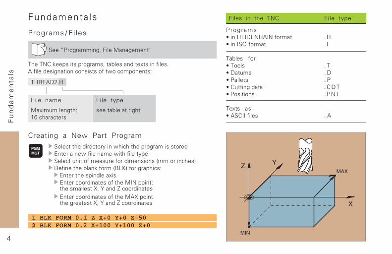
Creating a New Part Program���� ���������� ���+����!�� ���������������������%��������!���������!����������+������ ��(���������(�����������������,������ ���-&�������������������,./0-���������� �"%��������������������%����� ������������������1�������"�����������2 �3����4� ���������%����� �������������������2������"������������2 �3����4� ���������
File type
.H
. I
. T
. D
. P
.CDT
.PNT
. A
Files in the TNC
Programs5����#%1&%�#�1������5����1�6�����
Tables ���5������5�&�(�5�������5��(��������5����������
Texts �5����11������
1 BLK FORM 0.1 Z X+0 Y+0 Z-502 BLK FORM 0.2 X+100 Y+100 Z+0
5
Fu
nd
ame
nta
ls
��������������������� ������������������������������������������
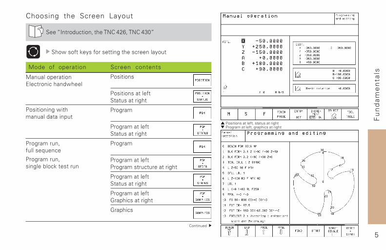
Choosing the Screen Layout
�����1�����( ���� ���������7'* �����789�
���!��������+������������������� ������+�(�
������ ���
Mode of operation Screen contents
���������
�������������������(���������
�����
���������������(���������
�����
���������������������( �(����������
���������������(���������
������������:���� ���������
:���� �
�������(� �(�����;(�� �
�������(� ���������� ��������(�
��(����������%�� ����� ����!����
������������!����(��������(�
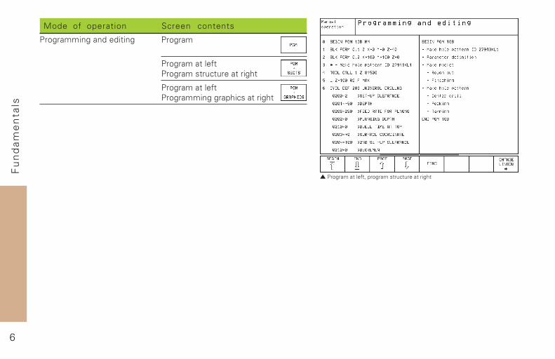
6
Fu
nd
ame
nta
ls
�������������������������� �� ����������
Mode of operation Screen contents
�����
���������������������( �(����������
�������������������������� ���������
�������������������
7
Fu
nd
ame
nta
ls
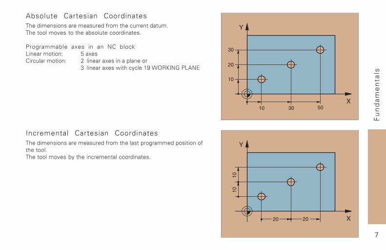
Incremental Cartesian Coordinates�������������������(������������������������������������������������������<���by������� ������� ����������
Absolute Cartesian Coordinates�������������������(������������ (��������(�����������<���to���������(��� ����������
Programmable axes in an NC block/����������" =������� (��������" ' ���������������������
8 ����������!���� + ���)>�?6$01�:��/��%
8
Fu
nd
ame
nta
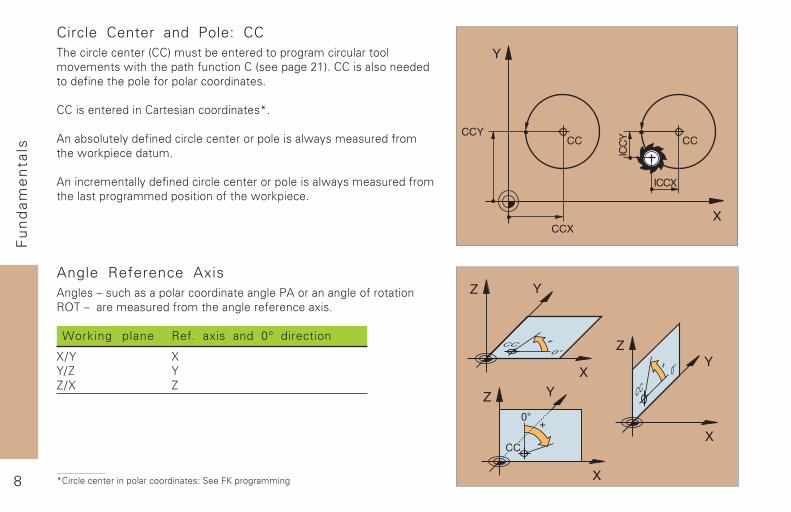
lsCircle Center and Pole: CC���� �� ��� ������,��-�(����������������������� �� (��������<������!�������������(� �������,��������')-���������������������������������������������� ����������
������������������������� ���������@�
�������(���+��������� �� ��� ������������������!+����(�����������!������ ����(�
����� �������+��������� �� ��� ������������������!+����(���������������������������������������!������ ��
Angle Reference Axis�������A��( ���������� �������������������������������������$6��A�������(������������������������ ������
Working plane Ref. axis and 0° direction
2B3 23B4 34B2 4
������������������ �������� ���������������� ����
9
Fu
nd
ame
nta
ls
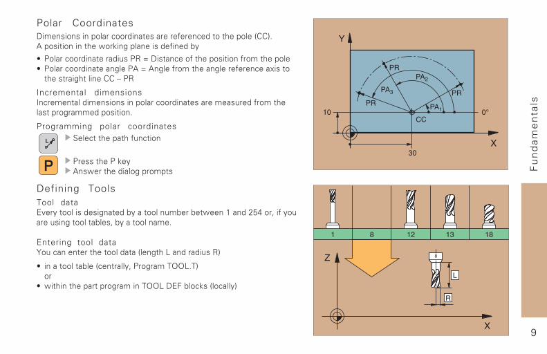
Polar Coordinates&����������������� �������������������� ���������������,��-�������������������!������������������������+
5 ����� ������������(���$�C�&���� ������������������������������5 ����� �����������������C��������������������������� ����������������������������A��$
Incremental dimensions1� ������������������������� ���������������(��������������������������������
Programming polar coordinates
Defining ToolsTool data%<��+��������������������+��������(�������!����)����'=7��� ����+�(���(��������������� ��+����������
Entering tool data3�(� ��������������������,�������/�������(��$-
5 ��������������, ������+ ��������66/��-��
5 !������������������������66/�&%����� ���,�� ��+-
���� �����������(� ����
��������������+���!�������������������
1 0
Fu
nd
ame
nta
ls
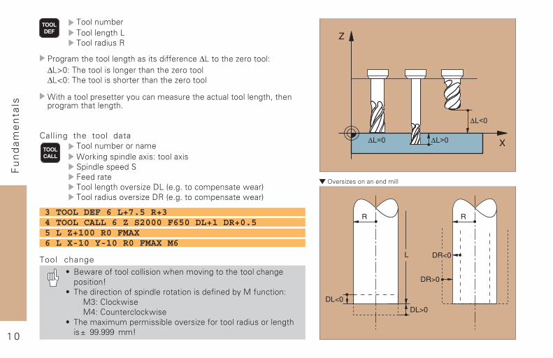
������������� ��������
������(���������������/��������(��$
������������������������������������ ��∆/��������D��������"∆/E9"����������������������������D��������∆/F9"�����������������������������D��������
?��������������������+�(� ����(������� �(������������� ����������������������
Calling the tool data������(���������?������������������"���������������������������������������������<����D��&/�,�������� ��������!��-��������(���<����D��&$�,�������� ��������!��-
3 TOOL DEF 6 L+7.5 R+34 TOOL CALL 6 Z S2000 F650 DL+1 DR+0.55 L Z+100 R0 FMAX6 L X-10 Y-10 R0 FMAX M6
Tool change5 .�!����������� ���������!�����<���������������� ������������G
5 �������� ������������������������������������+����(� ����"�8"���� �!����7"���(���� �� �!���
5 ������(�������������<����D��������������(��������������HI>>�>>>IG
1 1
Fu
nd
ame
nta
ls
�S���� ��� E�����
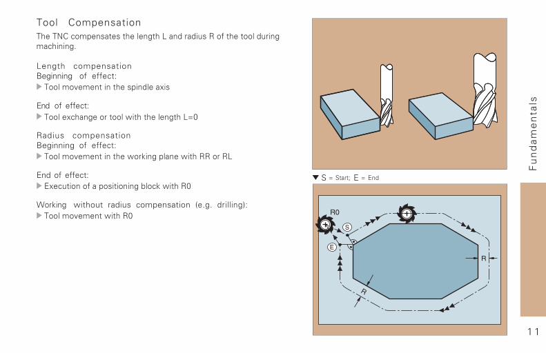
Tool Compensation�������� ��������������������/�������(��$��������������(���� �������
Length compensationBeginning ��� ���� �"������<�����������������������
End ��� ���� �"������� �������������!���������������/C9
Radius compensationBeginning� ��� ���� �"������<������������!������������!����$$����$/
End� ��� ���� �"%�� (������������������������ ��!����$9
?������� without radius compensation� ,����� ��������-"������<�����!����$9
1 2
Fu
nd
ame
nta
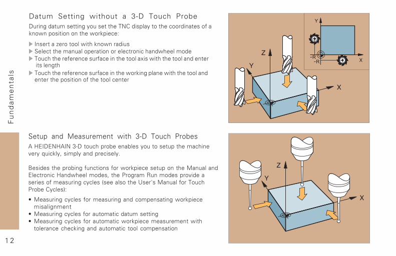
lsDatum Setting without a 3-D Touch Probe&(�������(���������+�(������������������+�������� ����������������!������������������!������ �"
1�������D���������!�������!�����(����� �������(����������������� ����� ����!����������( ������������� ���(�� ������������������!����������������������������������( ������������� ���(�� ���������!������������!���������������������������������������������� �����
Setup and Measurement with 3-D Touch Probes��#%1&%�#�1��8J&���( ���������������+�(�������(������ ����<��+�;(� ��+ �����+������� ����+�
.��������������������(� ����������!������ �����(�����������(����%�� ����� �#��!��������� �����������$(����������<����������������(����� + ����,������������K���L����(��������( ��������+ ���-"
5 ���(����� + ����������(�������� ����������!������ ����������
5 ���(����� + ��������(���� ���(��������5 ���(����� + ��������(���� �!������ ����(������!��������� �� �� ��������(���� � ����� ���������
1 3
Co
nto
ur
Ap
pro
ach
and
D
ep
artu
re
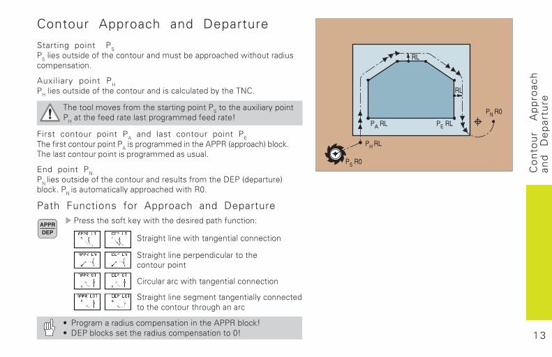
Contour Approach and Departure
Starting point PS
�������������������� ���������������������� ��������������
�����������
Auxiliary point PH
�������������������� ������������ �� ���������������
��������������������������������������������������������
��������������������������������������
First contour point PA and last contour point PE
��������� �������������������������������������� ������ �!���� "�
�������� ���������������������������������
End point PN
���
����������������� ������������������������#$�� �������!��� "���
����������� ����������� ��������%�
Path Functions for Approach and Departure�������������"����������������������� ���&
'������������������������ ���� ���
'������������������ ��������� ����������
��� ������� �������������� ���� ���
'����������������������������� ���� ������ ������������������
( ���������������� ������������������������� "�( #$����� "�������������� �������������%�
1 4
Co
nto
ur
Ap
pro
ach
and
D
ep
artu
re
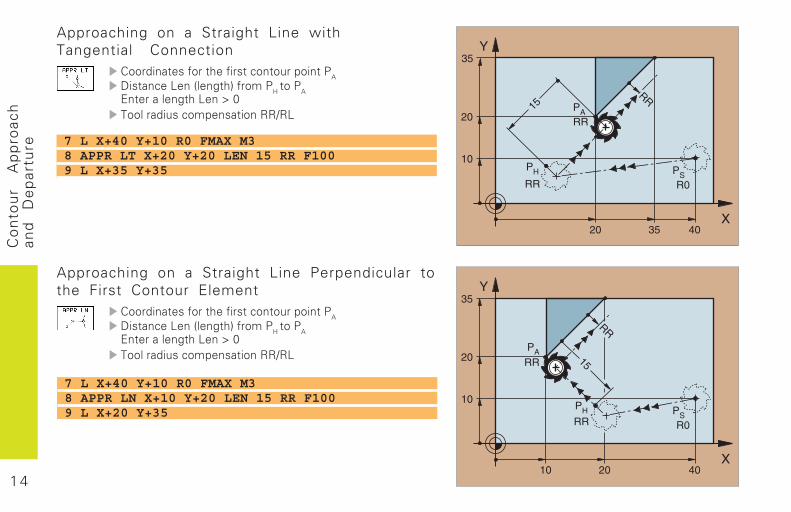
Approaching on a Straight Line Perpendicular tothe First Contour Element
���������������������� �������������
#���� ��)��� �����!���������
����
$������������)���*�%����������� �������������+�)
Approaching on a Straight Line withTangential Connection
���������������������� �������������
#���� ��)��� �����!���������
����
$������������)���*�%����������� �������������+�)
7 L X+40 Y+10 R0 FMAX M38 APPR LT X+20 Y+20 LEN 15 RR F1009 L X+35 Y+35
7 L X+40 Y+10 R0 FMAX M38 APPR LN X+10 Y+20 LEN 15 RR F1009 L X+20 Y+35
1 5
Co
nto
ur
Ap
pro
ach
and
D
ep
artu
re
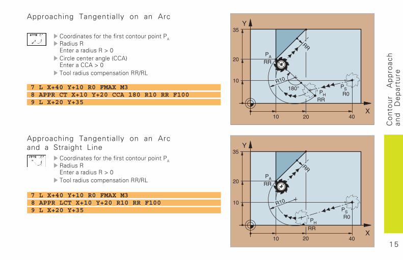
Approaching Tangentially on an Arcand a Straight Line
���������������������� �������������
�������$��������������*�%����������� �������������+�)
7 L X+40 Y+10 R0 FMAX M38 APPR CT X+10 Y+20 CCA 180 R10 RR F1009 L X+20 Y+35
7 L X+40 Y+10 R0 FMAX M38 APPR LCT X+10 Y+20 R10 RR F1009 L X+20 Y+35
Approaching Tangentially on an Arc
���������������������� �������������
�������$��������������*�%��� ��� ����������� ���!$����������*�%����������� �������������+�)
1 6
Co
nto
ur
Ap
pro
ach
and
D
ep
artu
re
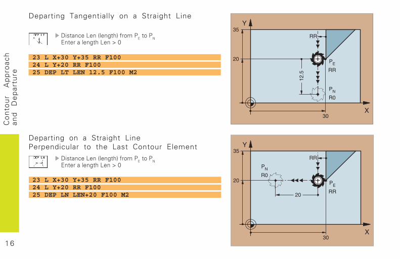
Departing on a Straight LinePerpendicular to the Last Contour Element
#���� ��)��� �����!������������
�$������������)���*�%
Departing Tangentially on a Straight Line
#���� ��)��� �����!������������
�$������������)���*�%
23 L X+30 Y+35 RR F10024 L Y+20 RR F10025 DEP LT LEN 12.5 F100 M2
23 L X+30 Y+35 RR F10024 L Y+20 RR F10025 DEP LN LEN+20 F100 M2
1 7
Co
nto
ur
Ap
pro
ach
and
D
ep
artu
re
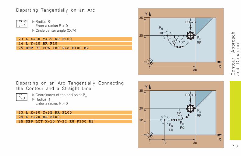
�������$��������������*�%��� ��� ����������� ���!
Departing on an Arc Tangentially Connectingthe Contour and a Straight Line
��������������������������
�������$��������������*�%
23 L X+30 Y+35 RR F10024 L Y+20 RR F1025 DEP CT CCA 180 R+8 F100 M2
23 L X+30 Y+35 RR F10024 L Y+20 RR F10025 DEP LCT X+10 Y+12 R8 F100 M2
Departing Tangentially on an Arc
1 8
Pat
h
Fu
nct
ion
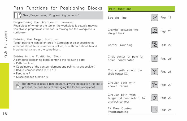
sPath functions
Straight line
Chamfer �������� ������� �������
Corner rounding
Circle center � pole forpolar coordinates
Circular path ������ ���������������
Circular path withknown radius
Circular path withtangential connection ����������������
FK Free ContourP rog ramming
���� 19
���� 20
���� 22
���� 21
���� 21
���� 23
���� 20
���� 25
Path Functions for Positioning Blocks
���������������������������������
Programming the Direction of Traverse������������� �� ��� ���������� ������������������� �������! ����� ������������� ��������������������� ������������������� �
Entering the Target Positions"�����������������������������������������������������#��� �����������������������������!������ ���� ������������������������������� ������������
Entries in the Positioning Block$������������������������������������� ���������������% �� ���������% �������������� ����������������������������&�������������'% ��������������������(�)(�*% +�������+% ,���������������������,
-����� ����.��������������!��� ����/���������� ����������������� ������������ ������������ �����������������0
1 9
Pat
h
Fu
nct
ion
s
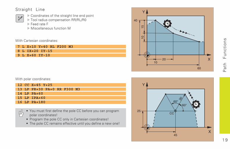
1�� ���������������
Straight Line�������������� ������ ����������������"�����������������������(�)(�*+�������+,���������������������,
1�� ������������������
7 L X+10 Y+40 RL F200 M38 L IX+20 IY-159 L X+60 IY-10
12 CC X+45 Y+2513 LP PR+30 PA+0 RR F300 M314 LP PA+6015 LP IPA+6016 LP PA+180
% 2��������������������� ���������������� �����������������������0
% ������ ������������� ��������������������0% " �������������������������������� ������������������0
2 0
Pat
h
Fu
nct
ion
s
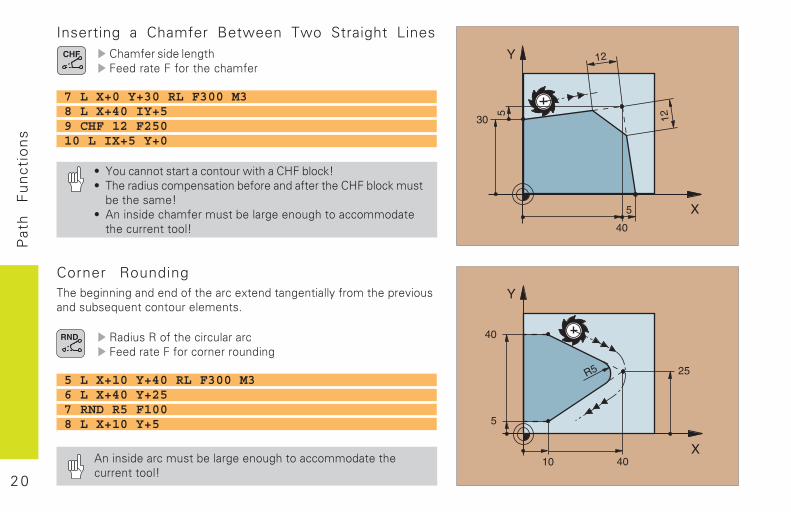
Corner Rounding" ����������������������� �����.�������������� ������ �����������������3���������������������
������������ ���������+�������+����������������
Inserting a Chamfer Between Two Straight Lines� �������������� +�������+����� ��� ���
7 L X+0 Y+30 RL F300 M38 L X+40 IY+59 CHF 12 F25010 L IX+5 Y+0
% 2������������������������ ���4+������0% " ��������������������������������� ���4+��������������� �����0
% $���������� ��������������������� �������������� ������������0
5 L X+10 Y+40 RL F300 M36 L X+40 Y+257 RND R5 F1008 L X+10 Y+5
$���������������������������� ��������������� �����������0
2 1
Pat
h
Fu
nct
ion
s
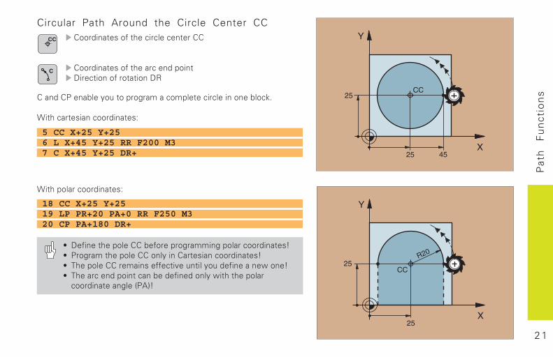
Circular Path Around the Circle Center CC�������������� ����������������
�������������� �������������5������������������5�
�������������� ����������������������������������������
1�� ������������������
1�� ���������������
5 CC X+25 Y+256 L X+45 Y+25 RR F200 M37 C X+45 Y+25 DR+
18 CC X+25 Y+2519 LP PR+20 PA+0 RR F250 M320 CP PA+180 DR+
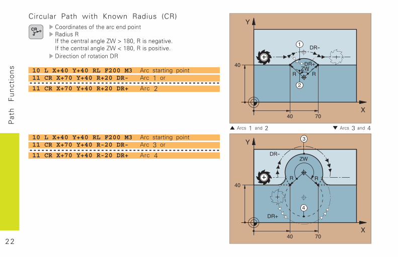
% 5������� ��������������������������������������0% ������ ������������� ��������������������0% " �������������������������������� ������������������0% " ������������������������������� ���� �� �������������������&�$'0
2 2
Pat
h
Fu
nct
ion
s
� ����� 1� ���� 2 � ����� 3� ���� 4
10 L X+40 Y+40 RL F200 M3 Arc starting point11 CR X+70 Y+40 R-20 DR- Arc 3 or
11 CR X+70 Y+40 R-20 DR+ Arc 4
Circular Path with Known Radius (CR)�������������� ��������������������6��� �������������71�8�9:*!��������������6��� �������������71�;�9:*!���������������5������������������5�
10 L X+40 Y+40 RL F200 M3 Arc starting point11 CR X+70 Y+40 R+20 DR- Arc 1 or
11 CR X+70 Y+40 R+20 DR+ Arc 2
2 3
Pat
h
Fu
nct
ion
s
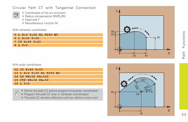
Circular Path CT with Tangential Connection�������������� ���������������������������������(�)(�*+�������+,���������������������,
1�� ������������������
1�� ���������������
5 L X+0 Y+25 RL F250 M36 L X+25 Y+307 CT X+45 Y+208 L Y+0
12 CC X+40 Y+3513 L X+0 Y+35 RL F250 M314 LP PR+25 PA+12015 CTP PR+30 PA+3016 L Y+0
% 5������� ��������������������������������������0% ������ ������������� ��������������������0% " �������������������������������� ������������������0
2 4
Pat
h
Fu
nct
ion
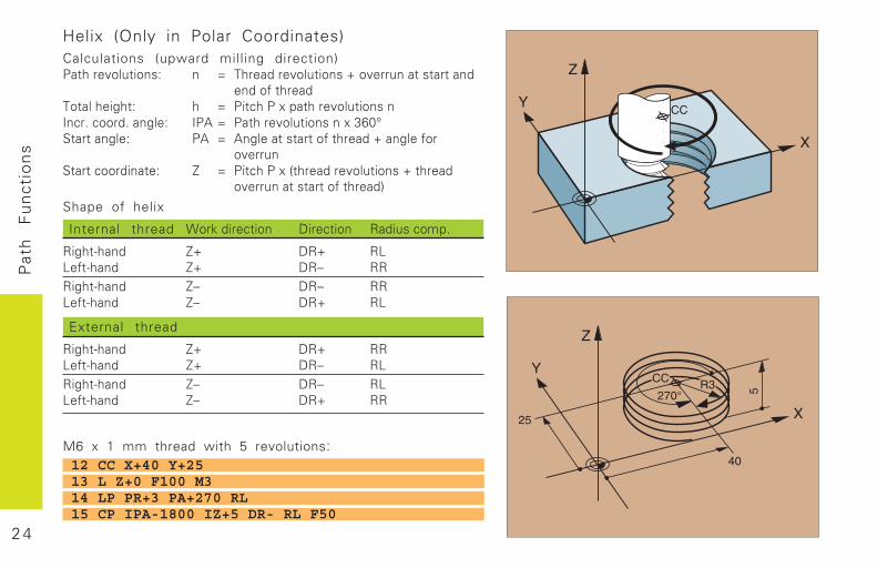
sHelix (Only in Polar Coordinates)Calculations (upward milling direction)�� ������������ � < " ��������������=���������������
�������� ��"���� ��� �� < ���� ���.��� �������������6��������������� 6�$ < �� ��������������.�>?*@��������� �$ < $��������������� ���=��������
������������������ 7 < ���� ���.�&� ��������������=�� ��
���������������� ��'
Shape of helix
Internal thread 1����������� 5������� �����������
��� �/ �� 7= 5�= �))���/ �� 7= 5�# ����� �/ �� 7# 5�# ��)���/ �� 7# 5�= �)
External thread
��� �/ �� 7= 5�= ��)���/ �� 7= 5�# �)��� �/ �� 7# 5�# �))���/ �� 7# 5�= ��
M6 x 1 mm thread with 5 revolutions:12 CC X+40 Y+2513 L Z+0 F100 M314 LP PR+3 PA+270 RL15 CP IPA-1800 IZ+5 DR- RL F50
2 5
FK
F
ree
C
on
tou
rP
rog
ram
min
g
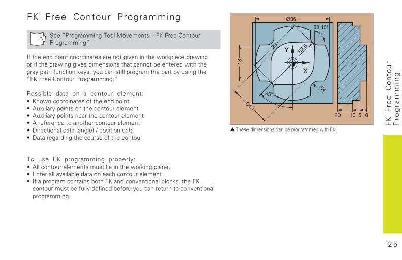
FK Free Contour Programming
�������������� ���������������������������������������
��������������������������������������������������� �������������������������������������������������������!��������������������"�������������� �"�#�"��������������������������!"�����������������������������������$�
Possible data on a contour element:% ���������������������������������% &�'����"�����������������������������% &�'����"������������������������������% &�����������������������������������% (�������������)����*�+������������% (������������������������������������
To use FK programming properly:% &������������������������������������� ��������$% ,�����������!���������������������������$% ������������������!����������������������!��� �#�������������������!������"���������!������"�����������������������������������$
������������������ �������������������
2 6
FK
F
ree
C
on
tou
rP
rog
ram
min
g
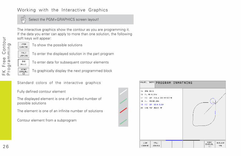
Standard colors of the interactive graphics
����"�����������������������
��������"������������������������������!����������!������������
���������������������������������!���������������
����������������������!�����
Working with the Interactive Graphics
������������-�.-/&�0������������"���1
�����������������������������������������"�����������������$����������"���������������"������������������������#������������������� �"�����������2
����������������!������������
�����������������"����������������������������
�����������������!��3��������������������
����������"������"�������'����������!���
2 7
FK
F
ree
C
on
tou
rP
rog
ram
min
g
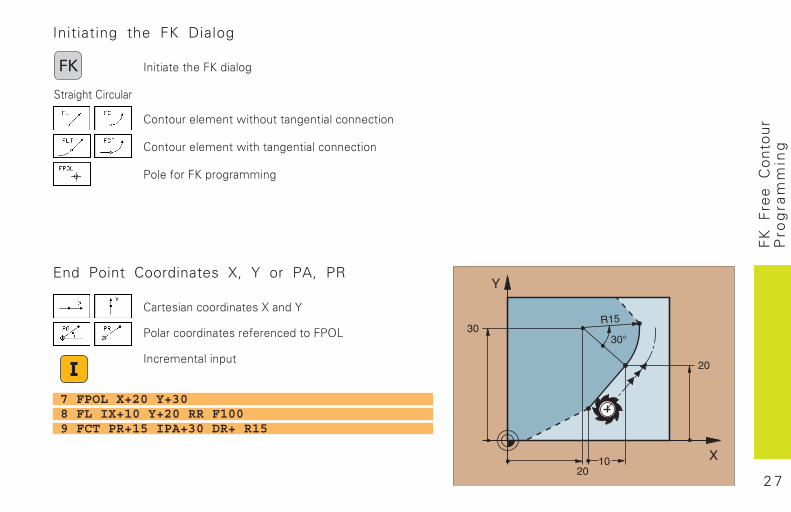
Initiating the FK Dialog
��������������������
������������������������������������������
���������������������������������������
��������������������
������� �������
End Point Coordinates X, Y or PA, PR
�������������������4����5
��������������������������������67
���������������
7 FPOL X+20 Y+308 FL IX+10 Y+20 RR F1009 FCT PR+15 IPA+30 DR+ R15
2 8
FK
F
ree
C
on
tou
rP
rog
ram
min
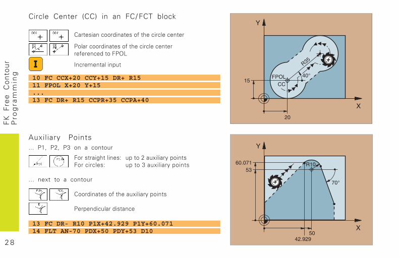
gCircle Center (CC) in an FC/ FCT block
���������������������������������������
����������������������������������������������������67
���������������
Auxiliary Points... P1, P2, P3 on a contour
�����������������2 ������8��'����"������������������2 ������9��'����"�������
... next to a contour
�������������������'����"�������
��������������������
10 FC CCX+20 CCY+15 DR+ R1511 FPOL X+20 Y+15...13 FC DR+ R15 CCPR+35 CCPA+40
13 FC DR- R10 P1X+42.929 P1Y+60.07114 FLT AN-70 PDX+50 PDY+53 D10
2 9
FK
F
ree
C
on
tou
rP
rog
ram
min
g
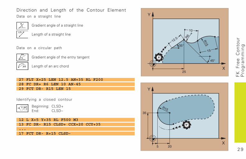
Direction and Length of the Contour ElementData on a straight line
-����������������������������
7����������������������
Data on a circular path
-�����������������������"�������
7�������������������
27 FLT X+25 LEN 12.5 AN+35 RL F20028 FC DR+ R6 LEN 10 AN-4529 FCT DR- R15 LEN 15
Identifying a closed contour
:��������2 �7�(.,��2 �7�(�
12 L X+5 Y+35 RL F500 M313 FC DR- R15 CLSD+ CCX+20 CCY+35...17 FCT DR- R+15 CLSD-
3 0
FK
F
ree
C
on
tou
rP
rog
ram
min
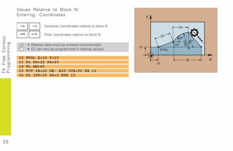
gValues Relative to Block N:Entering Coordinates
������������������������������!��� �;
���������������������������!��� �;
% /��������������!��������������������"1% ����������!��������������������������1
12 FPOL X+10 Y+1013 FL PR+20 PA+2014 FL AN+4515 FCT IX+20 DR- R20 CCA+90 RX 1316 FL IPR+35 PA+0 RPR 13
3 1
FK
F
ree
C
on
tou
rP
rog
ram
min
g
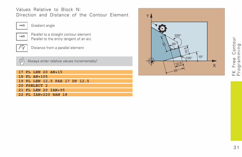
Values Relative to Block N:Direction and Distance of the Contour Element
-�����������
���������������������������������������������������"���������������
(�������������������������
&��"��������������������������������"1
17 FL LEN 20 AN+1518 FL AN+10519 FL LEN 12.5 PAR 17 DP 12.520 FSELECT 221 FL LEN 20 IAN+9522 FL IAN+220 RAN 18
3 2
FK
F
ree
C
on
tou
rP
rog
ram
min
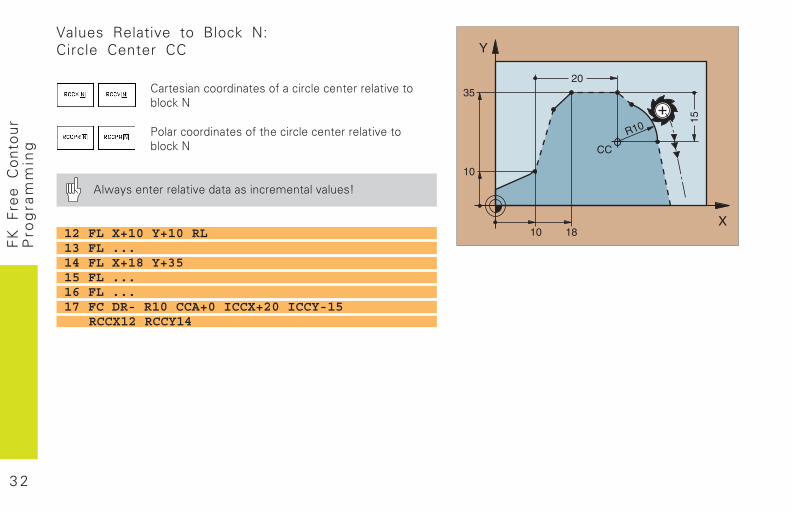
gValues Relative to Block N:Circle Center CC
�����������������������������������������������!��� �;
�����������������������������������������������!��� �;
&��"������������������������������������1
12 FL X+10 Y+10 RL13 FL ...14 FL X+18 Y+3515 FL ...16 FL ...17 FC DR- R10 CCA+0 ICCX+20 ICCY-15
RCCX12 RCCY14
3 3
Su
bp
rog
ram
s
���� �S���������R�������� ���
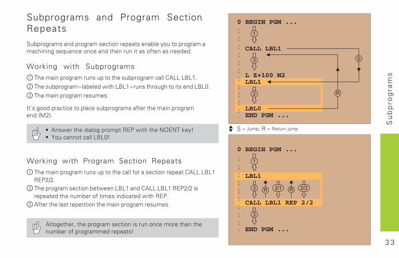
Subprograms and Program SectionRepeats
������������ �������������������������������������������������������������������� �������������������������� � �
Working with Subprograms
� �����������������������������������������������������
� ��������������������� ��������������������������������� ���� �
� ��������������������
!�"���� �������������������������������������������������� �#$%&�
' ���������� ������������()*����������+,)+��-��.' /������������������ .
Working with Program Section Repeats
� ���������������������������������������������������������������()*%0%�
� ��������������������������������� �����������()*%0%��������� �������������������� ����� ������()*�
� ���������������������������������������������
����������1���������������������������������������������������������� �������.
3 4
Su
bp
rog
ram
s
S���������R�������� ����
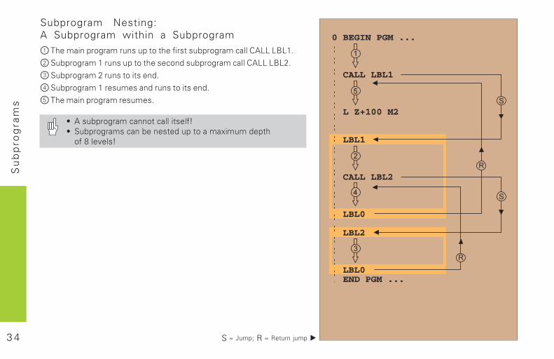
Subprogram Nesting:A Subprogram within a Subprogram
� ����������������������������������������������������������
� ������������������������������ �����������������������%�
� ����������%������������� �
� ������������������� ������������� �
� ��������������������
' ����������������������������.' ��������������������� ����������2��� �������3���4��.
3 5
Su
bp
rog
ram
s
�S���������R�������� ���
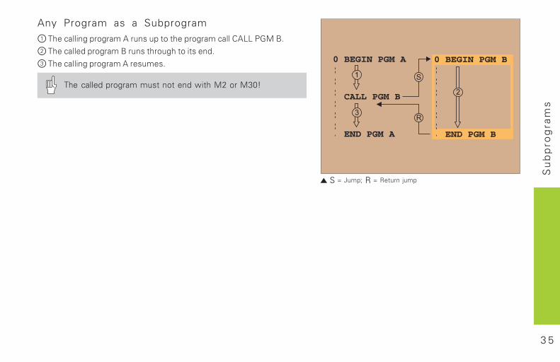
Any Program as a Subprogram
� ����������������������������������������������������*5$���
� ��������� ������������������������������ �
� ��������������������������
����called����������������� ������$%����$6 .
3 6
Wo
rkin
g
wit
h
Cyc
les
Drill ing Cycles
� ������� ��� ���� �������� �������� ������� �������� ������ ������� ������������������ ���� ��� ���������������� �������� ����������������� �������� ������������ ������ ������� ����
��� ����������! ������ ������������� ������� ����������������! ������� �"������������ �����
���������������� ��
Pockets, Studs, and Slots
� �������������� �������� �������#����"��� ������� �����#����"��� ������ ����������������������� ����
��� ����������������#����"��� �������� ��������������#����"��� ����� ������������ �����
��� �����!��"������$������� ���� ��� ������������� �����
Point Patterns
��� ���������������� �������� �������������� �����
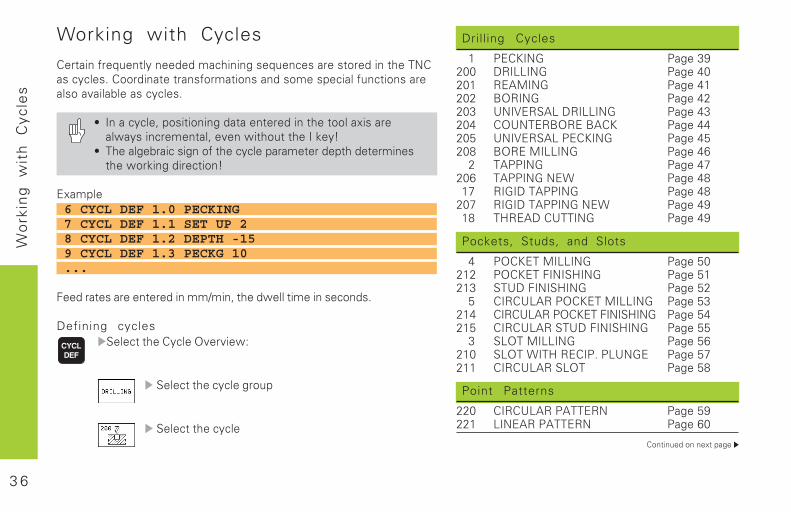
Working with Cycles
��%&'(�)%�*+�(&,-�(��.�.�/01'('(�2�*+�(0�2�%��2&3%�.�'(�&1�����2�0-0,�2$��33%.'(&��&%(2)3%/&'3(2�(.�23/��24�0',�)+(0&'3(2�%�,23�5',6,��2�0-0,�2$
7 �(��0-0,�8�432'&'3('(�.&��(&�%�.�'(�&1��&33,�9'2�%�,:-2�'(0%�/�(&,8��5�(�:'&13+&�&1����;�-<
7 �1��,�6%'0�2'(�3)�&1��0-0,��4%/�&�%�.�4&1�.�&�%/'(�2&1��:3%;'(�.'%�0&'3(<
�9/4,�6 CYCL DEF 1.0 PECKING7 CYCL DEF 1.1 SET UP 28 CYCL DEF 1.2 DEPTH -159 CYCL DEF 1.3 PECKG 10...
#��.�%&�2�%���(&�%�.�'(�//=/'(8�&1��.:�,,�&'/��'(�2�03(.2$
Defining cycles��,�0&�&1���-0,���5�%5'�:>
��,�0&�&1��0-0,��%3+4
��,�0&�&1��0-0,�
3 7
Wo
rkin
g
wit
h
Cyc
les
SL Cycles
�� ���������������? ������� ������������ ���� �� �������������� ������� ����"@��� ������ #�����#����"��� ������� �����#����"��� ������� ������������� ������ �?����������#��� ���� �� �?����������#�������� �����
Multipass Milling
� ����������A������� ������ � ����������������� ��� �� � ���������#��� ��� �
Cycles for Coordinate Transformations
�������"�#� ��� �� ������������ ��� �� �������� ��� ��� !������������ ��� ��� ��������#����� ��� ��� �B��@�����#���������� ���
Special Cycles
� �!�������� ��� ��� �������� ��� �� ��������������������� ��� � � ��������� �����
3 8
Wo
rkin
g
wit
h
Cyc
les
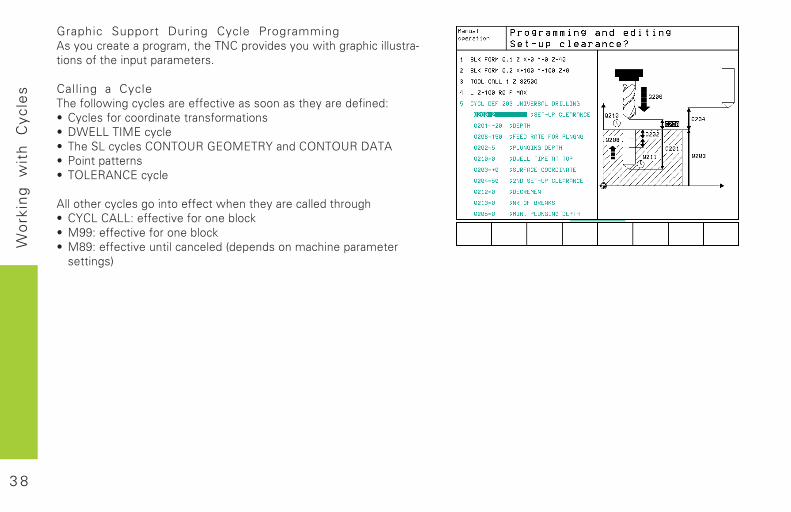
Graphic Support During Cycle Programming�2�-3+�0%�&���4%3%/8�&1������4%35'.�2�-3+�:'&1�%41'0�',,+2&%@&'3(2�3)�&1��'(4+&�4%/�&�%2$
Calling a Cycle�1��)3,,3:'(�0-0,�2�%���))�0&'5��2�233(�2�&1�-�%��.�)'(�.>7 �-0,�2�)3%�033%.'(&��&%(2)3%/&'3(27 �!���������0-0,�7 �1�����0-0,�2����������������?�(.�������������7 �3'(&�4&&�%(27 ����������0-0,�
�,,�3&1�%�0-0,�2�3�'(&3��))�0&�:1�(�&1�-�%��0,,�.�&1%3+17 �?�������>��))�0&'5��)3%�3(��6,30;7 ���>��))�0&'5��)3%�3(��6,30;7 ���>��))�0&'5��+(&',�0(0�,�.�C.�4�(.2�3(�/01'(��4%/�&�%2�&&'(2D
3 9
Dri
llin
g
Cyc
les
Drilling Cycles
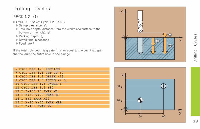
PECKING (1)������������ ���������������
���� ��������� A�� ��������� ���� ! ����"��#� ��$��%� ��!��"��� �� �&� �#��"� �����'��B��% �(� �� ��� C�$��� #� ��!����!����� ��
�"� �� � ��������� �� !�(�� �� �������)���� �� ����% �(��� �* �� ������ ��!� ��� ������ ���������(+
6 CYCL DEF 1.0 PECKING7 CYCL DEF 1.1 SET UP +28 CYCL DEF 1.2 DEPTH -159 CYCL DEF 1.3 PECKG +7.510 CYCL DEF 1.4 DWELL 111 CYCL DEF 1.5 F8012 L Z+100 R0 FMAX M613 L X+30 Y+20 FMAX M314 L Z+2 FMAX M9915 L X+80 Y+50 FMAX M9916 L Z+100 FMAX M2
4 0
Dri
llin
g
Cyc
les
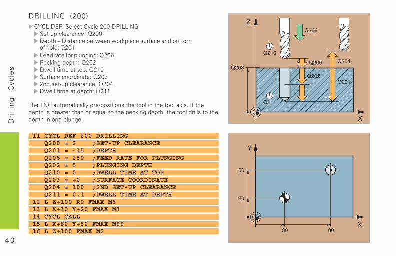
DRILLING (200)������������ ������,--��.������
�������������/,--�� ��0�� ! ����& $��$��%� ��!��"�������&� �#�"������/,-������ �"�������( �(��/,-1��% �(��� ���/,-,�$��� #�� � ����/,�-��"�������� �� ��/,-2,���! �������������/,-3�$��� #�� ��� ���/,��
��������� �#� �����������! ��!� �� ���� �� �� �����4 !+��"� ��� �� !�(�� �� �������)���� �� ����% �(��� �*� �� ������ ��!� �� ��� �� ���������(+
11 CYCL DEF 200 DRILLING Q200 = 2 ;SET-UP CLEARANCE Q201 = -15 ;DEPTH Q206 = 250 ;FEED RATE FOR PLUNGING Q202 = 5 ;PLUNGING DEPTH Q210 = 0 ;DWELL TIME AT TOP Q203 = +0 ;SURFACE COORDINATE Q204 = 100 ;2ND SET-UP CLEARANCE Q211 = 0.1 ;DWELL TIME AT DEPTH12 L Z+100 R0 FMAX M613 L X+30 Y+20 FMAX M314 CYCL CALL15 L X+80 Y+50 FMAX M9916 L Z+100 FMAX M2
4 1
Dri
llin
g
Cyc
les
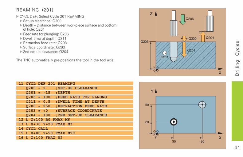
REAMING (201)������������ ������,-��.�56���
�������������/,--�� ��0�� ! ����& $��$��%� ��!��"�������&� �#�"������/,-������ �"�������( �(��/,-1�$��� #�� ��� ���/,��. ��� ���"���� ��/,-7��"�������� �� ��/,-2,���! �������������/,-3
��������� �#� �����������! ��!� �� ���� �� �� �����4 !+
11 CYCL DEF 201 REAMING Q200 = 2 ;SET-UP CLEARANCE Q201 = -15 ;DEPTH Q206 = 100 ;FEED RATE FOR PLNGNG Q211 = 0.5 ;DWELL TIME AT DEPTH Q208 = 250 ;RETRACTION FEED RATE Q203 = +0 ;SURFACE COORDINATE Q204 = 100 ;2ND SET-UP CLEARANCE12 L Z+100 R0 FMAX M613 L X+30 Y+20 FMAX M314 CYCL CALL15 L X+80 Y+50 FMAX M9916 L Z+100 FMAX M2
4 2
Dri
llin
g
Cyc
les
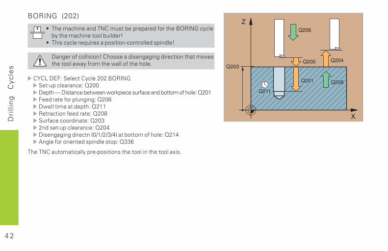
BORING (202)
8 ���#��� ����������#�! �&��������"��� ��9:.��������&�� ��#��� �� ����&� ���;
8 �� !�������)� �!�����! ������ ������!� ���;
���(���"����� ! ��;�����!���� !�(�( �(�� �� ��� �� �#�<! �� �����$���"��#� ��$�����"� �����+
������������ ������,-,�9:.��� �������������/,--�� ��=�� ! ����& $��$��%� ��!��"�������&� �#��"������/,-������ �"�������( �(��/,-1�$��� #�� ��� ���/,��. ��� ���"���� ��/,-7��"�������� �� ��/,-2,���! �������������/,-3� !�(�( �(�� �� ���->�>,>2>3'�� �&� �#��"������/,�35�(��"����� � ��!� ����! ����/221
��������� �#� �����������! ��!� �� ���� �� �� �����4 !+
4 3
Dri
llin
g
Cyc
les
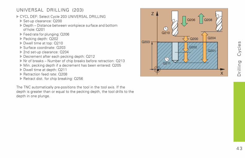
UNIVERSAL DRILLING (203)������������ ������,-2�?��@�.5���.������
�������������/,--�� ��0�� ! ����& $��$��%� ��!��"�������&� �#�"������/,-������ �"�������( �(��/,-1��% �(��� ���/,-,�$��� #�� � ����/,�-��"�������� �� ��/,-2,���! �������������/,-3���#� ��" ��������% �(��� ���/,�,����"�&��%!�0���#&���"��� ��&��%!�&"���� ��� ����/,�26 �+���% �(��� �� "������#� ���!�&��� ����/,-A�$��� #�� ��� ���/,��. ��� ���"���� ��/,-7. ��� �� ! +�"����� ��&��% �(��/,A1
��������� �#� �����������! ��!� �� ���� �� �� �����4 !+��"� ��� �� !�(�� �� �������)���� �� ����% �(��� �*� �� ������ ��!� �� ��� �� ���������(+
4 4
Dri
llin
g
Cyc
les
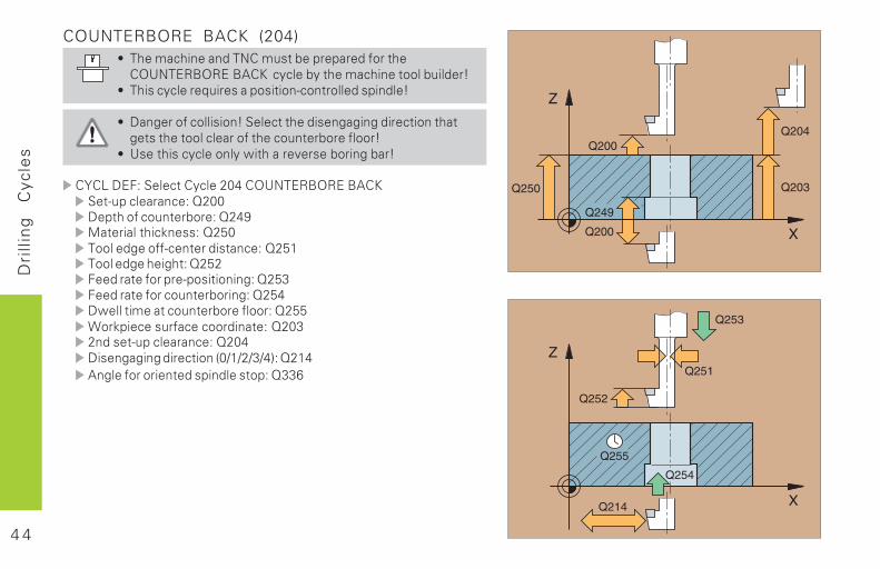
COUNTERBORE BACK (204)8 ���#��� ����������#�! �&��������"��� �
�:?���.9:.��95�� �����&�� ��#��� �� ����&� ���;8 �� !�������)� �!�����! ������ ������!� ���;
8 ���(���"����� ! ��;��� � ��� !�(�( �(�� �� ��� �� ( !� �� ����������"� ������ �&���"����;
8 ?!� � !�����������$ �����<�!�&�� �(�&��;
������������ ������,-3��:?���.9:.��95�� �������������/,--�� ���"����� �&����/,3B6� � ��� � �%�!!��/,A-������(��""��� ��� ! �����/,A�������(�� (� ��/,A,����� �"��������! �� �(��/,A2����� �"������� �&�� �(��/,A3�$��� #�� ����� �&���"������/,AAC��%� ��!��"�������� �� ��/,-2,���! �������������/,-3� !�(�( �(�� �� ����->�>,>2>3'��/,�35�(��"����� � ��!� ����! ����/221
4 5
Dri
llin
g
Cyc
les
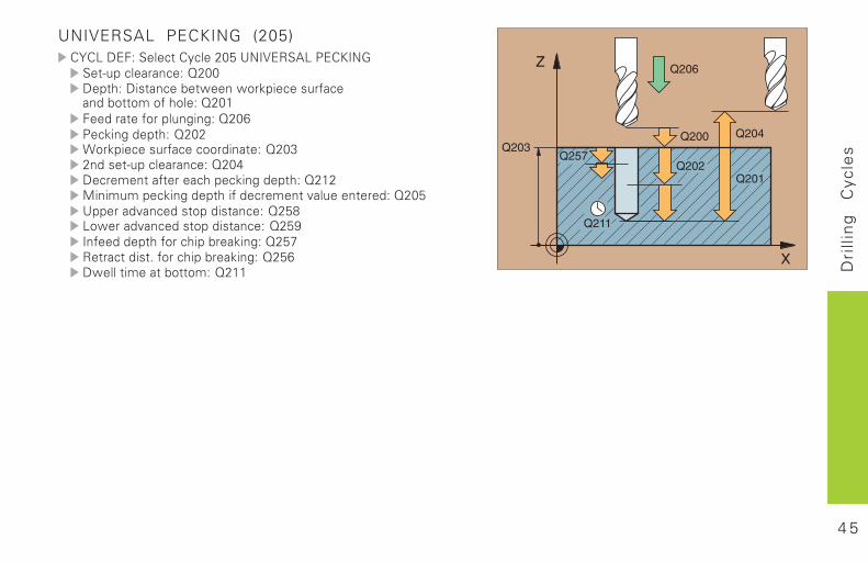
UNIVERSAL PECKING (205)������������ ������,-A�?��@�.5���������
�������������/,--�� ���� ! ����& $��$��%� ��!��"������&� �#��"������/,-������ �"�������( �(��/,-1��% �(��� ���/,-,C��%� ��!��"�������� �� ��/,-2,���! �������������/,-3���#� ��" ��������% �(��� ���/,�,6 � #�#���% �(��� �� "����#� �<����� ����/,-A?������<�����! ���� ! �����/,A7��$����<�����! ���� ! �����/,AB��"���� ��"����� ��&��% �(��/,AD. ��� �� ! +�"����� ��&��% �(��/,A1�$��� #�� �&� �#��/,��
4 6
Dri
llin
g
Cyc
les
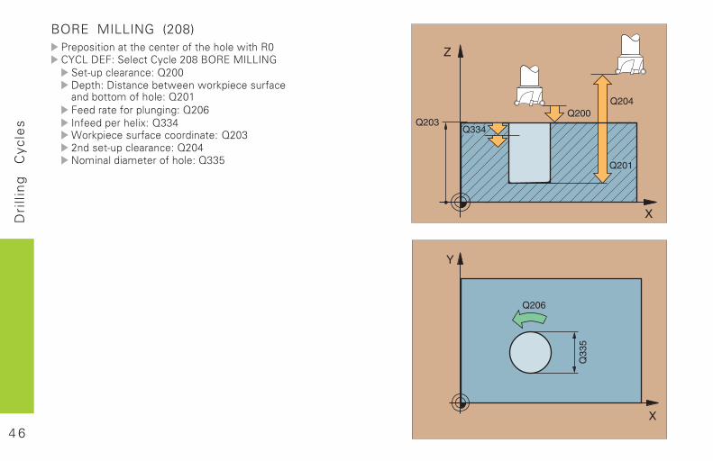
BORE MILLING (208)����! ���� � ���� ���"� ������$ ��.-������������ ������,-7�9:.��6������
�������������/,--�� ���� ! ����& $��$��%� ��!��"������&� �#��"������/,-������ �"�������( �(��/,-1��"������� 4��/223C��%� ��!��"�������� �� ��/,-2,���! �������������/,-3��# ����� �# ���"������/22A
4 7
Dri
llin
g
Cyc
les
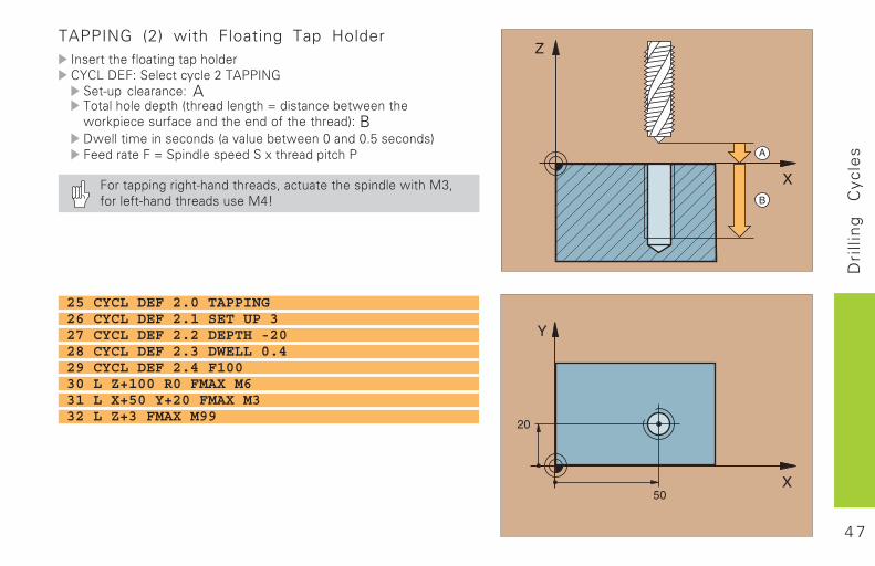
TAPPING (2) with Floating Tap Holder��!� � ��"��� �(� �������������������� ������,��5�����
���� ��������� A�� ��������� ��� �������( ��E�� ! ����& $�� �$��%� ��!��"������� ������"� �� ����'��B�$��� #� ��!����!����<����& $��-�����-+A�!����!'����� ���E�� ����!����4� ������ ����
���� ��� �(�� (� ������ ����!*��� �� � ��!� ����$ ��62*"����" ������ ����!��!�63;
25 CYCL DEF 2.0 TAPPING26 CYCL DEF 2.1 SET UP 327 CYCL DEF 2.2 DEPTH -2028 CYCL DEF 2.3 DWELL 0.429 CYCL DEF 2.4 F10030 L Z+100 R0 FMAX M631 L X+50 Y+20 FMAX M332 L Z+3 FMAX M99
4 8
Dri
llin
g
Cyc
les
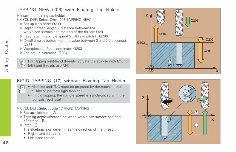
RIGID TAPPING (17) without Floating Tap Holder8 6��� ����������#�! �&��������&�� ��#��� �� ���
&� ���� ����"��#�� ( �� ��� �(;8 ���� ( �� ��� �(*� ��!� ����!��� !�!������� F��$ �� �
�����4 !�"���� ;
������������ �������D�.������5����� ���� ��������� A���� �(��� ���� ! ����& $��$��%� ��!��"����������"� ����'�� B� ���� C�����(&�� ��! (��� �# �!� ��� �� ����"� �� �����8 . (� ������ ������G8 �" ������ ������0
TAPPING NEW (206) with Floating Tap Holder��!� � ��"��� �(� �������������������� ������,-1��5��������C
�������������/,--�� ��� �������( ��E�� ! ����& $�� �$��%� ��!��"������� ������"� �� ������/,-������ ���E�!� ����!����4� ������ ������/,-1�$��� #�� �&� �#��� ����<����& $��-�����-+A�!����!'�/,��C��%� ��!��"�������� �� ��/,-2,���! �������������/,-3
���� ��� �(�� (� ������ ����!*��� �� � ��!� ����$ ��62*�"���" ������ ����!��!�63;
4 9
Dri
llin
g
Cyc
les
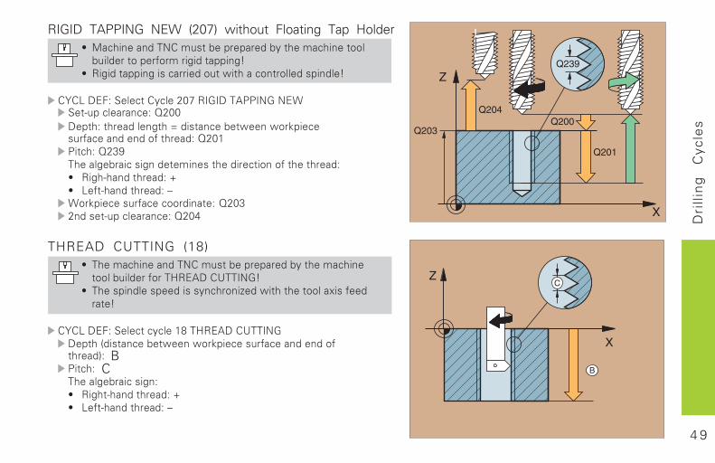
RIGID TAPPING NEW (207) without Floating Tap Holder8 6��� ����������#�! �&��������&�� ��#��� �� ���
&� ���� ����"��#�� ( �� ��� �(;8 . ( �� ��� �(� !����� ���� �$ ������� ������!� ���;
������������ ������,-D�.������5��������C �������������/,--�� ��� �������( ��E�� ! ����& $��$��%� �!��"�����������"� ������/,-�� ����/,2B�����(&�� ��! (��� # �!� ��� �� ����"� �� �����8 . (������� ������G8 �" ������ ������0C��%� ��!��"�������� �� ��/,-2,���! �������������/,-3
THREAD CUTTING (18)8 ���#��� ����������#�! �&��������&�� ��#��� �
����&� ����"����H.�5���?�����;8 ���!� ����!��� !�!������� F��$ �� �� �����4 !�"�
�� ;
������������ �������7��H.�5���?������� ���� ! ����& $��$��%� ��!��"�����������" ����'�� B� ���� C�����(&�� ��! (��8 . (� ������ ������G8 �" ������ ������0
Z
X
Q203
Q204Q200
Q201
Q239
5 0
Po
cke
ts,
Stu
ds,
an
d
Slo
ts
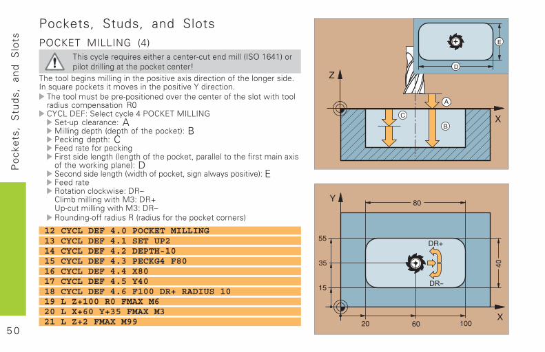
12 CYCL DEF 4.0 POCKET MILLING13 CYCL DEF 4.1 SET UP214 CYCL DEF 4.2 DEPTH-1015 CYCL DEF 4.3 PECKG4 F8016 CYCL DEF 4.4 X8017 CYCL DEF 4.5 Y4018 CYCL DEF 4.6 F100 DR+ RADIUS 1019 L Z+100 R0 FMAX M620 L X+60 Y+35 FMAX M321 L Z+2 FMAX M99
Pockets, Studs, and SlotsPOCKET MILLING (4)
���������������� ������ ��� ������������������������� ���������� � ������ ��� �
��� ���� ���������������� ������ �!��"������ �����#� ����������$������������ ��� ���!����� ������ �!�%���� ���$��� ������� � ������� ������!� ���� ��#� ����� �&� �� ���������������� ����R0'%'(�)*+,���� ��������-�'.*��/�((�01� ����������,�A/��������� ����� ���#� ������ �,�B-�������� �,�C+��� �#��������+�� �������� ������ ���#� ������ 2�������� �� ��#�� �������"���#� ��&�����������,�D������������� ���&�� ���#����� 2��������&�������� �!�,�E+��� 3� � ���������&��,�)34'��� ���������&� ��/5,�)367���� ���������&� ��/5,�)343���������##�������3��������#�� ������ ������
5 1
Po
cke
ts,
Stu
ds,
an
d
Slo
ts
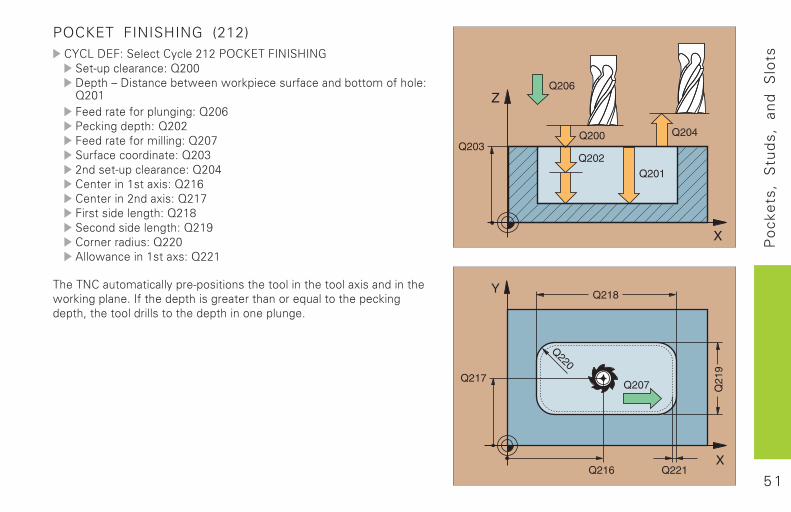
POCKET FINISHING (212)'%'(�)*+,���� �'����8�8�-�'.*��+�0��9�01� ����������,�:8;;)� ��4�)�� ���� &��&��������#������� � ����#����,:8;�+��� �#����������,�:8;�-�������� �,�:8;8+��� �#���������,�:8;<��#���������� ,�:8;58���� ����������,�:8;�'� ������ ��"��,�:8��'� ����8����"��,�:8�<+�� �������� �,�:8�=������������� �,�:8�>'��������,�:88;?���&��������� ��"�,�:88�
����0'��� ��� ������������� ����� �� ������� �� �����"���������� �&����������$��#� ���� ������� � ����������� �� ���������� �2� �� ���������� �� ���� �������������$
5 2
Po
cke
ts,
Stu
ds,
an
d
Slo
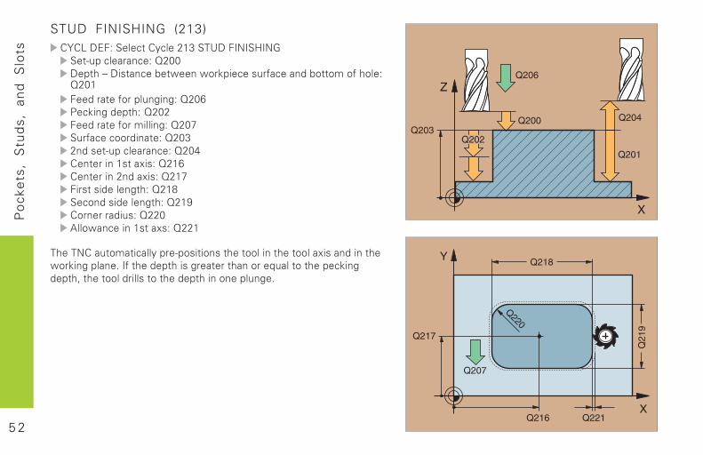
tsSTUD FINISHING (213)'%'(�)*+,���� �'����8�5���7)�+�0��9�01� ����������,�:8;;)� ��4�)�� ���� &��&��������#������� � ����#����,:8;�+��� �#����������,�:8;�-�������� �,�:8;8+��� �#���������,�:8;<��#���������� ,�:8;58���� ����������,�:8;�'� ������ ��"��,�:8��'� ����8����"��,�:8�<+�� �������� �,�:8�=������������� �,�:8�>'��������,�:88;?���&��������� ��"�,�:88�
����0'��� ��� ������������� ����� �� ������� �� �����"���������� �&����������$��#� ���� ������� � ����������� �� ���������� �2� �� ���������� �� ���� �������������$
5 3
Po
cke
ts,
Stu
ds,
an
d
Slo
ts
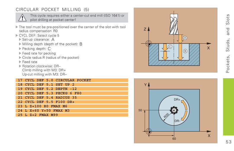
CIRCULAR POCKET MILLING (5)���������������� ������ ��� ������������������������� ���������� ����� ��� �
��� ������� � ������� ������!� ���� ��#� ����� �&� �� ���������������� ����R0'%'(�)*+,���� ������@� ����������,�A/��������� ����� ���#� ������ �,�B-�������� �,�C+��� �#��������'����������3���������#� ������ �+��� 3� � ���������&��,�)34'��� ���������&� ��/5,�)367���� ���������&� ��/5,�)34
17 CYCL DEF 5.0 CIRCULAR POCKET18 CYCL DEF 5.1 SET UP 219 CYCL DEF 5.2 DEPTH -1220 CYCL DEF 5.3 PECKG 6 F8021 CYCL DEF 5.4 RADIUS 3522 CYCL DEF 5.5 F100 DR+23 L Z+100 R0 FMAX M624 L X+60 Y+50 FMAX M325 L Z+2 FMAX M99
5 4
Po
cke
ts,
Stu
ds,
an
d
Slo
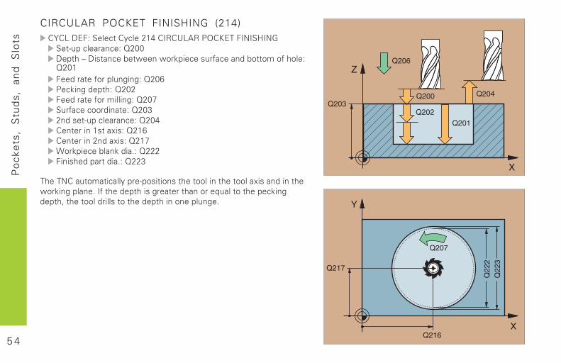
tsCIRCULAR POCKET FINISHING (214)'%'(�)*+,���� �'����8���'�3'7(?3�-�'.*��+�0��9�01� ����������,�:8;;)� ��4�)�� ���� &��&��������#������� � ����#����,:8;�+��� �#����������,�:8;�-�������� �,�:8;8+��� �#���������,�:8;<��#���������� ,�:8;58���� ����������,�:8;�'� ������ ��"��,�:8��'� ����8����"��,�:8�<A������ ��������$,�:888+��������� ����$,�:885
����0'��� ��� ������������� ����� �� ������� �� �����"���������� �&����������$��#� ���� ������� � ����������� �� ���������� �2� �� ���������� �� ���� �������������$
5 5
Po
cke
ts,
Stu
ds,
an
d
Slo
ts
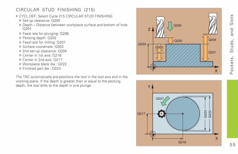
CIRCULAR STUD FINISHING (215)'%'(�)*+,���� �'����8�@�'�3'7(?3���7)�+�0��9�01� ����������,�:8;;)� ��4�)�� ���� &��&��������#������� � ����#����,:8;�+��� �#����������,�:8;�-�������� �,�:8;8+��� �#���������,�:8;<��#���������� ,�:8;58���� ����������,�:8;�'� ������ ��"��,�:8��'� ����8����"��,�:8�<A������ ��������$,�:888+��������� ����$,�:885
����0'��� ��� ������������� ����� �� ������� �� �����"���������� �&����������$��#� ���� ������� � ����������� �� ���������� �2� �� ���������� �� ���� �������������$
5 6
Po
cke
ts,
Stu
ds,
an
d
Slo
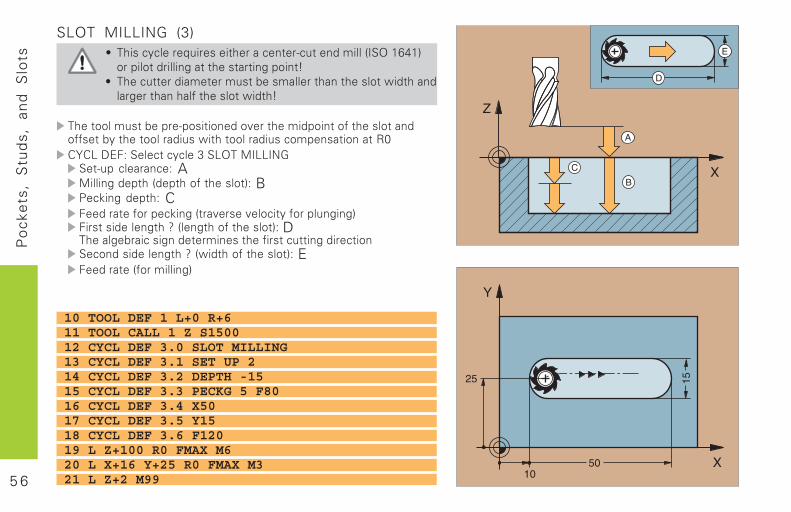
tsSLOT MILLING (3)
B ���������������� ������ ��� ������������������������� ���������� � ��� � �������� �
B ����� ����� ���� � ������� ���� ����� �&�� ��������� �������#� ����� �&�� ��
��� ������� � ������� ������!� ��������� ��#� ����� �����##� � �� �� ����������&� �� ����������������� ����� �R0'%'(�)*+,���� ������5��(���/�((�01� ����������,�A/��������� ����� ���#� ����� �,�B-�������� �,�C+��� �#���������� �!��!���� ��#�����������+�� �������� ��C����� ���#� ����� �,�D������ ���������� ����� ��#�� ��� ������� ���������������� ��C��&�� ���#� ����� �,�E+��� ��#����������
10 TOOL DEF 1 L+0 R+611 TOOL CALL 1 Z S150012 CYCL DEF 3.0 SLOT MILLING13 CYCL DEF 3.1 SET UP 214 CYCL DEF 3.2 DEPTH -1515 CYCL DEF 3.3 PECKG 5 F8016 CYCL DEF 3.4 X5017 CYCL DEF 3.5 Y1518 CYCL DEF 3.6 F12019 L Z+100 R0 FMAX M620 L X+16 Y+25 R0 FMAX M321 L Z+2 M99
5 7
Po
cke
ts,
Stu
ds,
an
d
Slo
ts
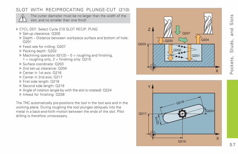
SLOT WITH RECIPROCATING PLUNGE-CUT (210)����� ����� ���� � �������� ���� ��&�� ���#� ���� 2�������������� ������� ����
'%'(�)*+,���� �'����8�;��(���3*'�-$�-(01� ����������,�:8;;)� ��4�)�� ���� &��&��������#������� � ����#����,:8;�+��� �#���������,�:8;<-�������� �,�:8;8/������������ �����;D�D8��4�;�E�������������#��������2��E�������������2�8�E�#�������������,�:8�@��#���������� ,�:8;58���� ����������,�:8;�'� ������ ��"��,�:8��'� ����8����"��,�:8�<+�� �������� �,�:8�=������������� �,�:8�>?�����#�� � ���������� ��&� �� ����� ����� � ��,�:88���#��#��#��������,�:55=
����0'��� ��� ������������� ����� �� ������� �� �����"���������� �&����������$�)������������� �� ������������ ��������� �� �� �������� ��������#� ���� ���� &�� �������#� ����� $�-��� ����������� �#����������$
5 8
Po
cke
ts,
Stu
ds,
an
d
Slo
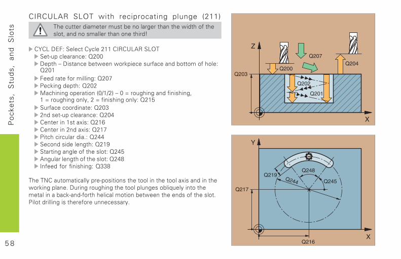
tsCIRCULAR SLOT with reciprocating plunge (211)
����� ����� ���� � �������� ���� ��&�� ���#� ���� 2�������������� ������� ����
'%'(�)*+,���� �'����8���'�3'7(?3��(��� ����������,�:8;;)� ��4�)�� ���� &��&��������#������� � ����#����,:8;�+��� �#���������,�:8;<-�������� �,�:8;8/������������ �����;D�D8��4�;�E�������������#��������2��E�������������2�8�E�#�������������,�:8�@��#���������� ,�:8;58���� ����������,�:8;�'� ������ ��"��,�:8��'� ����8����"��,�:8�<-� �������������$,�:8��������������� �,�:8�>� � ����������#� ����� ,�:8�@?��������� ���#� ����� ,�:8�=��#��#��#��������,�:55=
����0'��� ��� ������������� ����� �� ������� �� �����"���������� �&����������$�)������������� �� ������������ ��������� �� �� �������� ��������#� ����������� ���� &�� �������#� ����� $-��� ������������ �#����������$
5 9
Po
int
Pat
tern
s
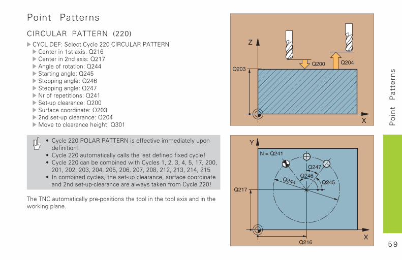
Point Patterns
CIRCULAR PATTERN (220)������������ ���������������������������� ������� ���������� �� �������!����������"��#��$%��$ � �$�����&& �� ��#���#�����&' $((��#���#�����& ((��#���#�����&"���$%��( � �$������&� )*(��������������*�%����$$�!��� �����+��!�� )*(�������������&,$-� $���������.�#. ���+��
/ ����������0���������������%%� �-��11!�� ���*($�!%��� �$�2
/ ����������* $1� ������������� .���� �!%��!�%��!�����2/ �������������3��$13��!�4� .��������5��5�+5�&5�'5��"5����5���5����5���+5���&5���'5��� 5���"5���65����5���+5���&5���'
/ ����$13��!������5� .�� )*(��������5��*�%����$$�!��� ��!���!�� )*()�������������4���� �7��%�$1���������2
�.������* $1� �������(�)($�� �$��� .� $$����� .� $$���������!���� .4$�7��#�(���8
6 0
Po
int
Pat
tern
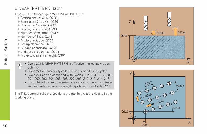
sLINEAR PATTERN (221)������������ ������������������������ �� �#�(� ��� ����������' �� �#�(� ���!���������� (����#������ ���������+"(����#������!���������+6�*13��$%��$�*1������&��*13��$%���������&+��#��$%��$ � �$������& )*(��������������*�%����$$�!��� �����+��!�� )*(�������������&,$-� $���������.�#. ���+��
/ ���������������������������%%� �-��11!�� ���*($�!%��� �$�2
/ ����������* $1� ������������� .���� �!%��!�%��!�����2/ �������������3��$13��!�4� .��������5��5�+5�&5�'5��"5����5���5����5���+5���&5���'5��� 5���"5���65����5���+5���&5���'
/ ����$13��!������5� .�� )*(��������5��*�%����$$�!��� ��!���!�� )*()�������������4���� �7��%�$1���������2
�.������* $1� �������(�)($�� �$��� .� $$����� .� $$���������!���� .4$�7��#�(���8
6 1
SL
C
ycle
s
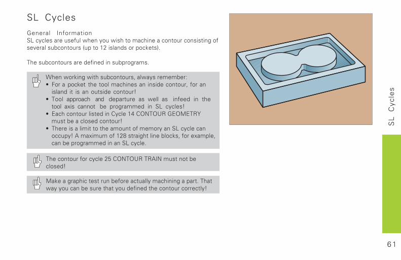
SL Cycles
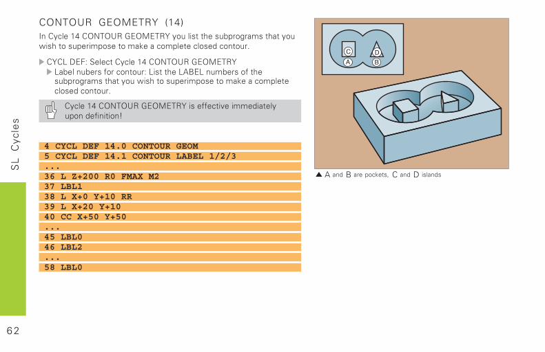
General Information������������������� �������� ��������������������������������������������������������������������������������
�������������������������������������
���� ������ ��������������!�� ���������"# $���pocket ��������������������������������!�����
island� ��� �������������������%# ���� approach ��� departure� �� ���� �� infeed in the
tool axis cannot ��� �������� ��� ��� ������%# &��������������������'������(�')*�)+,�-&).&�,/����������������������%# ��������������������������������������������������������%�0��1����������2�������������������!�����1����!����������������������������
���������������������3�')*�)+,��,04*������������������%
.������������������������������������������������ ��������������������������������������������������%
6 2
SL
C
ycle
s
�A����� B���������� � C����� D� �������
4 CYCL DEF 14.0 CONTOUR GEOM5 CYCL DEF 14.1 CONTOUR LABEL 1/2/3...36 L Z+200 R0 FMAX M237 LBL138 L X+0 Y+10 RR39 L X+20 Y+1040 CC X+50 Y+50...45 LBL046 LBL2...58 LBL0
CONTOUR GEOMETRY (14)4��'������(�')*�)+,�-&).&�,/������������������������������ �������������������������������������������������
'/'��5&$"��������'������(�')*�)+,�-&).&�,/��������������������"�����������06&�������������������������������� ������������������������������������������������
'������(�')*�)+,�-&).&�,/���������������������������������������%
6 3
SL
C
ycle
s
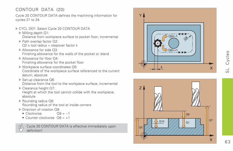
CONTOUR DATA (20)'������7�')*�)+,�50�0������������������������������������������������(�
'/'��5&$"��������'������7�')*�)+,�50�0.�������������8�"5����������� ����������������������������9����������:��������������8�"8��1�����������;���������������0��� ������������8<"$������������ ����������� �������������������������0��� ������������8("$������������ ���������������������� ������������������������83"'��������������� ���������������������������������������9�����������=����������8>"5��������������������������� �������������9����������'�������������8?"@�������� ���������������������������� �������� �������9�������,�������������82",���������������������������������������5������������������8A"# '���� ��� 8A�; B�# '����������� ��� 8A�; C�
'������7�')*�)+,�50�0���������������������������������������%
6 4
SL
C
ycle
sPILOT DRILLING (21)
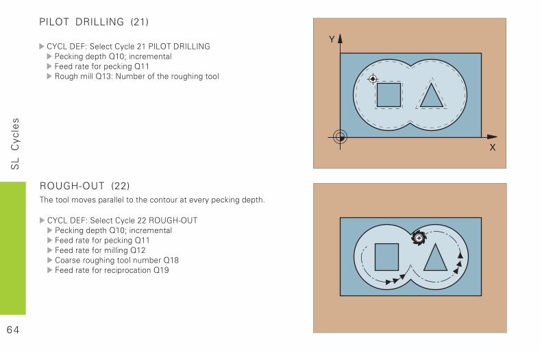
'/'��5&$"��������'��������:4�)��5,4��4*-:�������������8�79����������$������������������8��,����������8�<"�*������������������������
ROUGH-OUT (22)��������������������������������������������������������
'/'��5&$"��������'��������,)+-@=)+�:�������������8�79����������$������������������8��$������������������8��'�����������������������8�2$���������������������8�A
6 5
SL
C
ycle
s
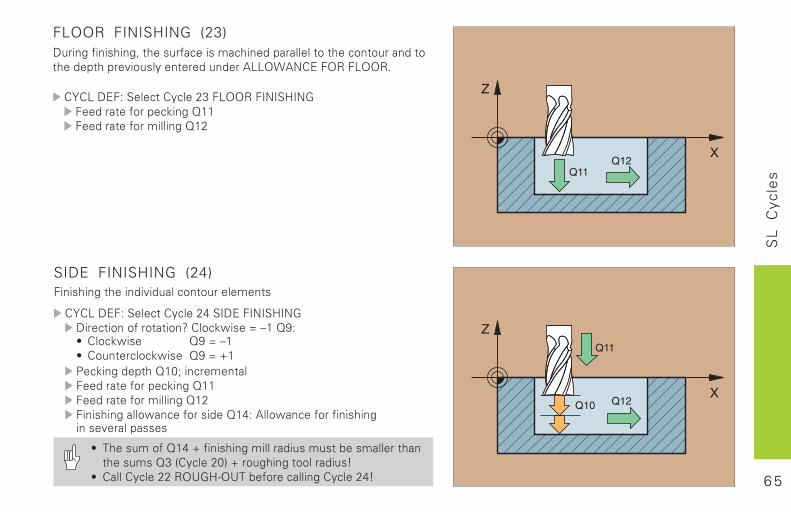
FLOOR FINISHING (23)5��������������!�������������������������������������������������������������������������������0��) 0*'&�$),�$�)),�
'/'��5&$"��������'������<�$�)),�$4*4�@4*-$������������������8��$������������������8��
SIDE FINISHING (24)$��������������������������������������
'/'��5&$"��������'������(��45&�$4*4�@4*-5�����������������D�'���� ����;�B��8A"# '���� ��� 8A�;�B�# '���������� ��� 8A�;�C�:�������������8�79����������$������������������8��$������������������8��$������������ ������������8�("�0��� ������������������������������
# �����������8�(�C�����������������������������������������������8<��'������7��C������������������%# '���'��������,)+-@=)+���������������'������(%
6 6
SL
C
ycle
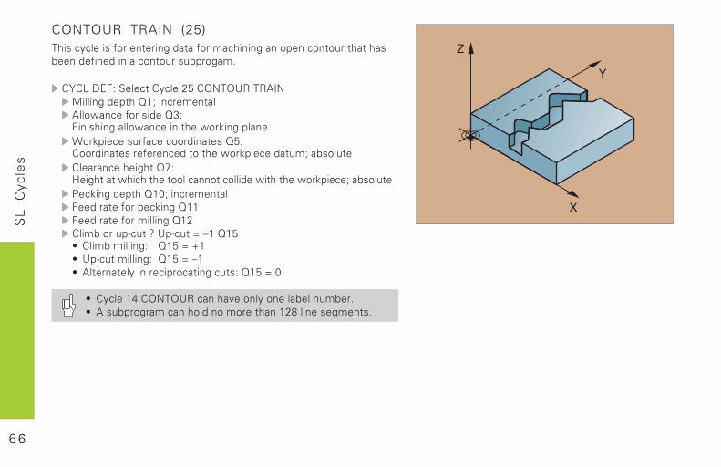
sCONTOUR TRAIN (25)��������������������������������������������������������������������������������������������
'/'��5&$"��������'������3�')*�)+,��,04*.�������������8�9����������0��� ������������8<"$������������ ����������� ���������� ������������������������83"'������������������������� ������������9��������'�������������8?"@�������� ���������������������������� �������� �������9��������:�������������8�79����������$������������������8��$������������������8��'���������=����D�+�=����;�B��8�3# '������������" 8�3�;�C�# +�=�����������" 8�3�;�B�# 0���������������������������"�8�3�;�7
# '������(�')*�)+,����������������������������# 0������������������������������2���������������
6 7
SL
C
ycle
s
CYLINDER SURFACE (27)
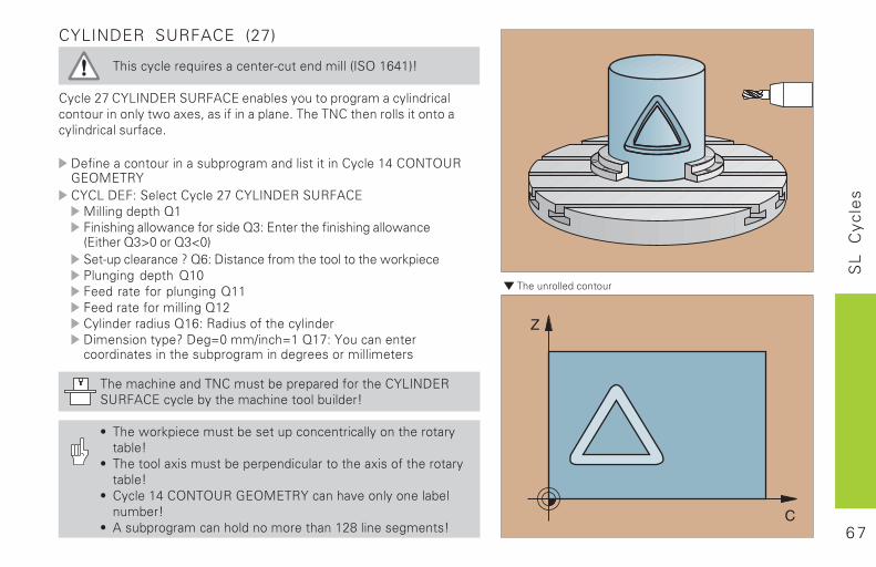
������������E�����������=��������������4�)��>(��%
'������?�'/�4*5&,��+,$0'&���������������������������������������������� ��1��!���������������������*'�����������������������������������
5����������������������������������������'������(�')*�)+,-&).&�,/'/'��5&$"��������'������?�'/�4*5&,��+,$0'&.�������������8�$������������ ������������8<"�&��������������������� ����&�����8<F7���8<G7����=����������D�8>"�5��������������������������� �������:��������������8�7$�������������������8��$������������������8��'������������8�>"�,�������������������5�������������D�5��;7���H����;��8�?"�/���������������������������������������������������������
���������������*'����������������������'/�4*5&,�+,$0'&��������������������������������%
# ���� ��������������������������������������������������%# ���������1�����������������������������1�����������������%# '������(�')*�)+,�-&).&�,/��������������������������%# 0������������������������������2��������������%
��������������������
6 8
SL
C
ycle
sCYLINDER SURFACE (28)
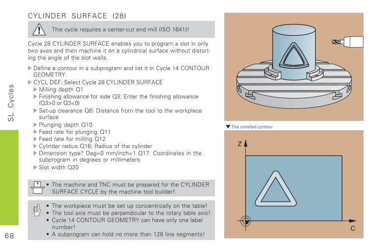
������������E�����������=��������������4�)��>(��%
'������2�'/�4*5&,��+,$0'&���������������������������������� ��1����������������������������������������� �������������=������������������������� ����
5����������������������������������������'������(�')*�)+,-&).&�,/�'/'��5&$"��������'������2�'/�4*5&,��+,$0'&.�������������8�$������������ ������������8<"�&��������������������� ����8<F7���8<G7����=����������8>"�5��������������������������� ������������:��������������8�7$�������������������8��$������������������8��'������������8�>"�,�������������������5�������������D�5��;7���H����;��8�?"�'����������������������� ��������������������������� �����8�7
# ���������������*'����������������������'/�4*5&,�+,$0'&�'/'�&��������������������������%
# ���� �����������������������������������������������%# ���������1��������������������������������������1��%# '������(�')*�)+,�-&).&�,/��������������������������%# 0������������������������������2��������������%
��������������������
6 9
Mu
ltip
ass
Mill
ing
Multipass Milling
RUN DIGITIZED DATA (30)
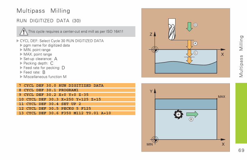
��������������� ����������������� �������������
������� !�����������"#�$%&���'���(����)�)�*��� ��+,���*���-��� � .�&/��,���� �*.)0/��,���� �*�������� ��!� A1�2��*�����!� C �� ��+,���2��*!�D �� �!� B.����� �,���+�����,��.
7 CYCL DEF 30.0 RUN DIGITIZED DATA8 CYCL DEF 30.1 PROGRAM19 CYCL DEF 30.2 X+0 Y+0 Z-3510 CYCL DEF 30.3 X+250 Y+125 Z+1511 CYCL DEF 30.4 SET UP 212 CYCL DEF 30.5 PECKG 5 F12513 CYCL DEF 30.6 F350 M112 T0.01 A+10
A
C X
Z
D
7 0
Mu
ltip
ass
Mill
ing
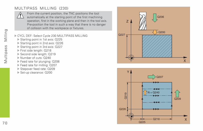
MULTIPASS MILLING (230) ,�����������,����,�3�����&���,����,�������,,� ��,� ��� ���� ������� ���*��,����,+����+����� ������*,� ��,�3�+����������4,2��*��� �� ��������������,,�� 5��/1��,����,������,,���������� �4 ���� ���������,�� �*,+��,�����,��4�������4,2����,�+�5���/
������� !�����������6"#�.%���1)���.����&'�� ���*��,����������� 5��!�7668�� ���*��,�������6��� 5��!�766��� ���*��,�������"�� 5��!�7669 ����������*��!�76�:��,���������*��!�76�;&��<�,+�����!�76�# �� ��+,�����*��*!�76#� �� ��+,�������*!�76#9���,=�+�� �!�76#;�������� ��!�76##
7 1
Mu
ltip
ass
Mill
ing
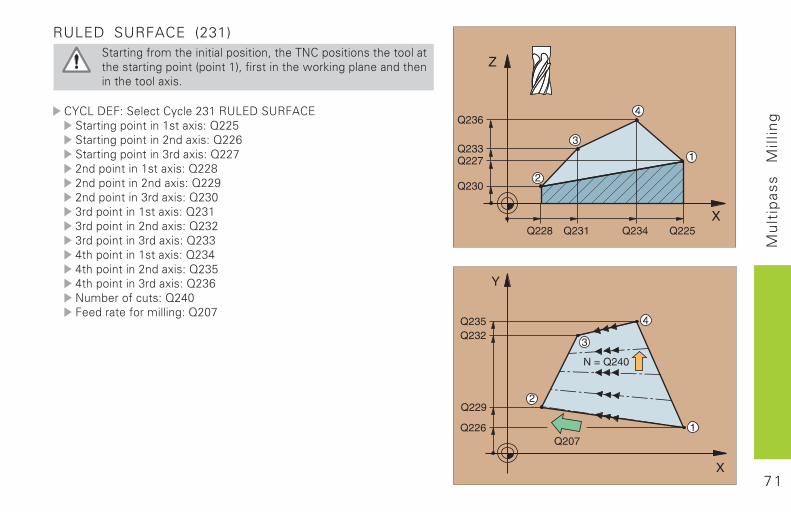
RULED SURFACE (231)�� ���*�+,���������� ���,����,�3�����&���,����,�������,,�� ������ ���*��,����>�,�����?3�+����������4,2��*��� �� �������������,,�� 5��/
������� !�����������6"��$%�����%$ )���� ���*��,����������� 5��!�7668�� ���*��,�������6��� 5��!�766��� ���*��,�������"�� 5��!�76696����,����������� 5��!�766:6����,�������6��� 5��!�766;6����,�������"�� 5��!�76"#"���,����������� 5��!�76"�"���,�������6��� 5��!�76"6"���,�������"�� 5��!�76""�����,����������� 5��!�76"������,�������6��� 5��!�76"8�����,�������"�� 5��!�76"�&��<�,+�����!�76�# �� ��+,�������*!�76#9
7 2
Cyc
les
for
Co
ord
inat
eT
ran
sfo
rma
tio
ns
Cycles for Coordinate Transformation
������������ ������ ������ �������� ��������
� ������� ����� � ������������ ���� ����� ��!!"!����#$� !������%� �������� �& ����� '( !"����")� ������������������� � ����� '* +"!,�)#�-.�)$� $ ��/���������� ����� '' ���.�)#
����� 01 �2��3�-$���������.�)#
������������ ������ ������ �����������4���� ����� ��� �� ���������������������� ��5������/� ���� ���������������� ���� ������/��5�� ����4�������� ����������������� ��� ���� ���5
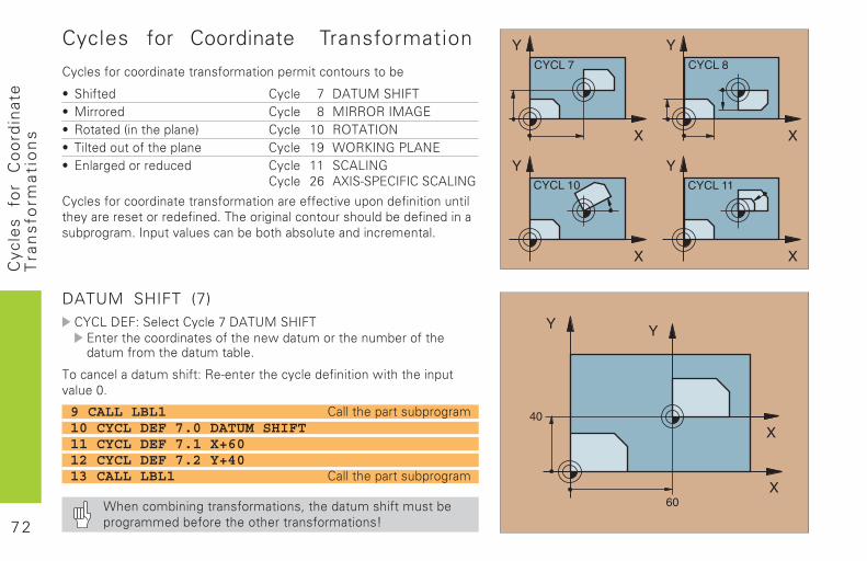
DATUM SHIFT (7)�6�.��$�7���������������������������$ ���������� ����������� �8������������ ����������������������������������5
���� �����������������7�!�3� ����������������� ��� �8��������� ���4�����(5
9 CALL LBL1 �����������������/��10 CYCL DEF 7.0 DATUM SHIFT11 CYCL DEF 7.1 X+6012 CYCL DEF 7.2 Y+4013 CALL LBL1 �����������������/��
+�� ����� � /��� ������ �9�������������������������/��������������������� ������ �:
7 3
Cyc
les
for
Co
ord
inat
eT
ran
sfo
rma
tio
ns
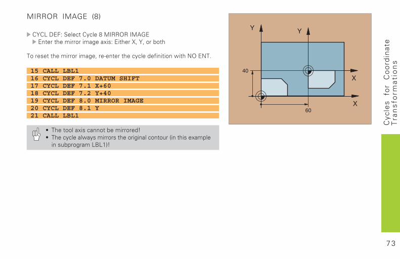
MIRROR IMAGE (8)
�6�.��$�7�������������� ���!!"!����#$$ �������������/���;��7�$�����29�69�����
�����������������/�9��3� ����������������� ��� �8����)"�$)�5
15 CALL LBL116 CYCL DEF 7.0 DATUM SHIFT17 CYCL DEF 7.1 X+6018 CYCL DEF 7.2 Y+4019 CYCL DEF 8.0 MIRROR IMAGE20 CYCL DEF 8.1 Y21 CALL LBL1
� ��������;����� ���������:� ������������8�������������/� ���� ���%� �������;������ �����/���.<.'&:
7 4
Cyc
les
for
Co
ord
inat
eT
ran
sfo
rma
tio
ns
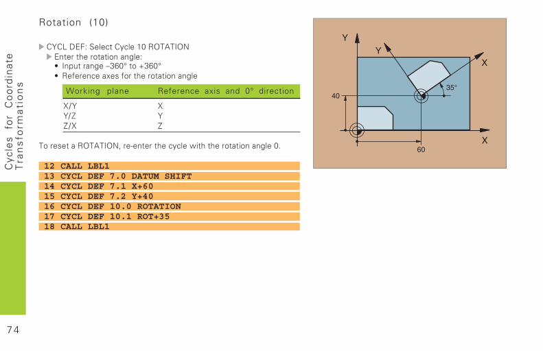
Rotation (10)
�6�.��$�7��������������'(�!"����")$ ����������� �� /��7� � ����� /��=>1(?���@>1(?� !���� ����;������������� �� /��
Working plane Reference axis and 0° direction
2A6 26AB 6BA2 B
���������!"����")9��3� �������������8������������ �� /���(5
12 CALL LBL113 CYCL DEF 7.0 DATUM SHIFT14 CYCL DEF 7.1 X+6015 CYCL DEF 7.2 Y+4016 CYCL DEF 10.0 ROTATION17 CYCL DEF 10.1 ROT+3518 CALL LBL1
7 5
Cyc
les
for
Co
ord
inat
eT
ran
sfo
rma
tio
ns
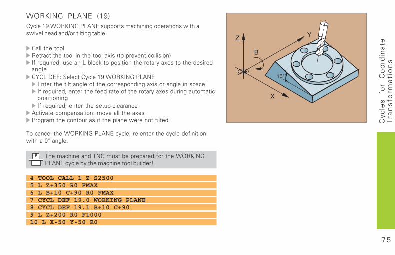
WORKING PLANE (19)������'*�+"!,�)#�-.�)$������������� � /������ ��8������8�4��������� �A������ /������5
�����������!�������������� ���������;���%����4� �������� &����C����9������ �.����D�������� ����������;���������������� /���6�.��$�7��������������'*�+"!,�)#�-.�)$$ ������������� /������������� �� /��;����� /���� ����������C����9�� ���������������������������;������ /�������������� � /����C����9�� ������������3����� ��
����4�������� ���� 7��4�����������;��-/�������� ���������������� ��8��� ��������
���� ��������+"!,�)#�-.�)$������9��3� ����������������� ��� 8������(?�� /��5
��������� ��� ���)�����������������������+"!,�)#-.�)$������������������� �����������:
4 TOOL CALL 1 Z S25005 L Z+350 R0 FMAX6 L B+10 C+90 R0 FMAX7 CYCL DEF 19.0 WORKING PLANE8 CYCL DEF 19.1 B+10 C+909 L Z+200 R0 F100010 L X-50 Y-50 R0
7 6
Cyc
les
for
Co
ord
inat
eT
ran
sfo
rma
tio
ns
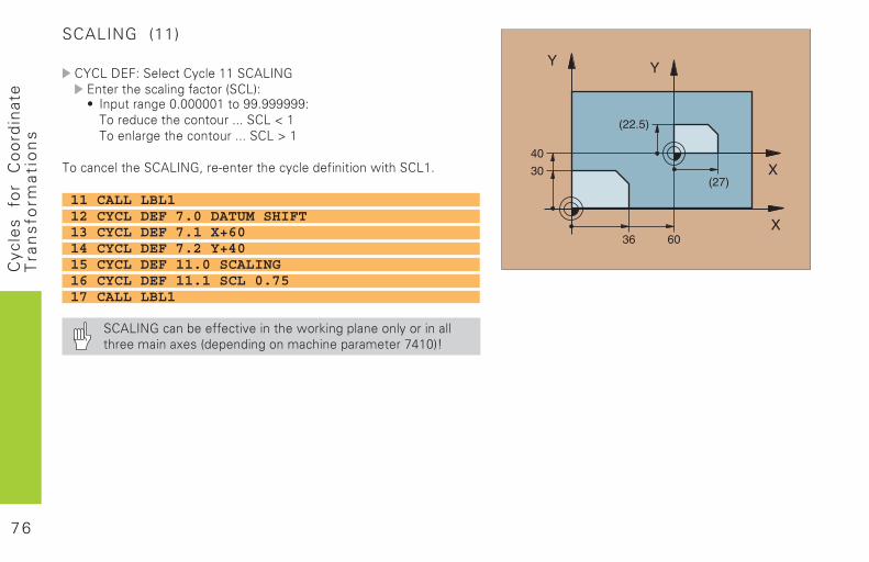
SCALING (11)
�6�.��$�7��������������''����.�)#$ ������������ /������%��.&7� � ����� /��(5((((('���**5******7������������� ���555���.�E�'��� ��/������� ���555���.�F�'
���� �����������.�)#9��3� ����������������� ��� �8������.'5
11 CALL LBL112 CYCL DEF 7.0 DATUM SHIFT13 CYCL DEF 7.1 X+6014 CYCL DEF 7.2 Y+4015 CYCL DEF 11.0 SCALING16 CYCL DEF 11.1 SCL 0.7517 CALL LBL1
���.�)#��� �����������4��� �����8D� /���� �� ����� ������������ ��;���%���� �� /� ������ �����������G'(&:
7 7
Cyc
les
for
Co
ord
inat
eT
ran
sfo
rma
tio
ns
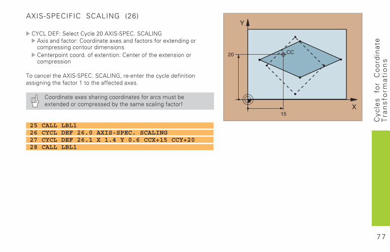
AXIS-SPECIFIC SCALING (26)
�6�.��$�7��������������0(��2��3�-$�5����.�)#�;���� ������7���� �����;���� �����������;�� �� /�������� /�� ������� �� ��� ���� ����5����;�� �� 7��� ����������;�� �� ��������
���� ���������2��3�-$�5����.�)#9��3� ����������������� ��� ����/ � /����������'�����������������;��5
��� �����;������� /���� �������������������;�� ������������������������������� /�����:
25 CALL LBL126 CYCL DEF 26.0 AXIS-SPEC. SCALING27 CYCL DEF 26.1 X 1.4 Y 0.6 CCX+15 CCY+2028 CALL LBL1
7 8
Sp
ec
ial-
Cy
cle
sSpecial Cycles
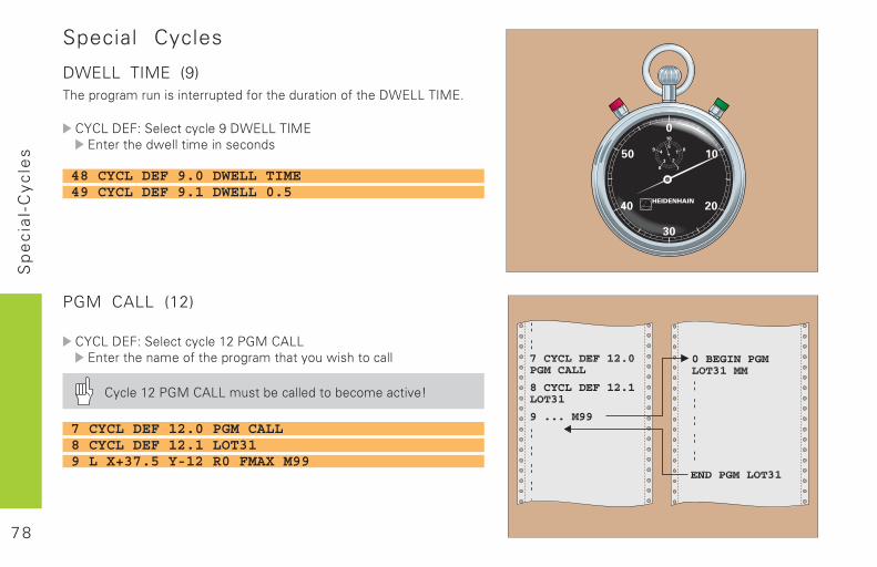
DWELL TIME (9)�������������� �� ����������������������� ���������������������
������������������ ����!����������������������"����� �� ���������
PGM CALL (12)
������������������ ����#$�%&���'�������������������������������� ���" ���������
� ����#$�%&���'�������(�����������(������� )�*
48 CYCL DEF 9.0 DWELL TIME49 CYCL DEF 9.1 DWELL 0.5
7 CYCL DEF 12.0 PGM CALL8 CYCL DEF 12.1 LOT319 L X+37.5 Y-12 R0 FMAX M99
7 9
Sp
ec
ial-
Cy
cle
s
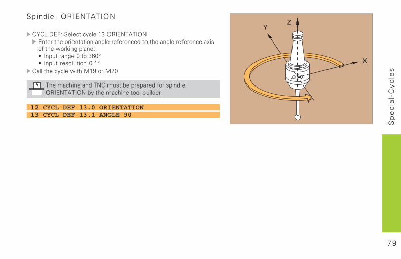
Spindle ORIENTATION
������������������ ����#+�,-��.�'��,.������������ ���� �����������������������������������������/ ��������"��0 ��������1 �����������2����+3241 ������ ������� ���2�#4
��������� ����" ����#!�����$2
������ �������.������(���������������� ����,-��.�'��,.�( ������� ��������(� ����*
12 CYCL DEF 13.0 ORIENTATION13 CYCL DEF 13.1 ANGLE 90
8 0
Sp
ec
ial-
Cy
cle
s
X
Z
T
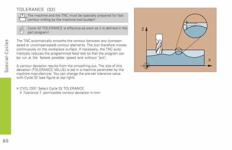
TOLERANCE (32)������ �����������.������(������ �� ������������������������ �� ���( ������� ��������(� ����*
� ����+$��,��-'.��� �������� )����������� �� ����� ���� ��������������*
�����.������ ��� ��������������������(��"����� �5�����6�������������������7��������������������������������������)������ ������ ��������"��0� ���������������������� 8������.�����6� ��� �������������������������������������������������(�� ���� �� ���� fastest possible ������ ���" ������ 9:��09�
'�����������) � ������������������������ ������������� ;������� ���) � ���5�,��-'.���<'�=�7� ������ ����� ����������( ������ ����������������������������������6�������������)���" ���� ����+$�5����� ������������ ���7�
������������������ ����+$��,��-'.����������������� �� (�������������) � ��� ��
8 1
Dig
itiz
ing
Digitizing 3D Surfaces������������������ ���������������������������������������������� �����
������������ ������������������������������������������������ ����� ���������� ������������������� ���� !"#$�%�!&�'$
���� !"#$�(%�!&�'$� )���������������������������� ���� !"#$�(*�+$&�)$!� )����������,��������,��� ���� !"#$�(-��"��".!�/0�$1� )���������� ���������������� ���� !"#$�(2�/0�$
�������������������������������������������������� ���������3��������������������������������������45�6���7�������������������������������&5�#����3
� )������������������������������������������������������������������������������,��
� )������������������������������3�����������������,������������ �����������
Selecting digitizing cycles
��������,��,��������� ���������� �����
1���������������������
�3�3��������������(%
8 2
Dig
itiz
ing
Digitizing Cycle RANGE (5)
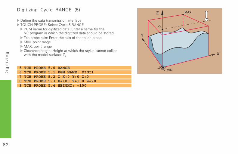
)���������������������������������".��� !"#$��1������������%�!&�'$ '+����������������������$������������������������������������������������������� ����������3����������������$���������������������� ��������+0�3����������+&43��������������������������������������������������� ���������������������������� �������7
�
5 TCH PROBE 5.0 RANGE6 TCH PROBE 5.1 PGM NAME: DIGI17 TCH PROBE 5.2 Z X+0 Y+0 Z+08 TCH PROBE 5.3 X+100 Y+100 Z+209 TCH PROBE 5.4 HEIGHT: +100
8 3
Dig
itiz
ing
Digitizing Cycle RANGE (15)
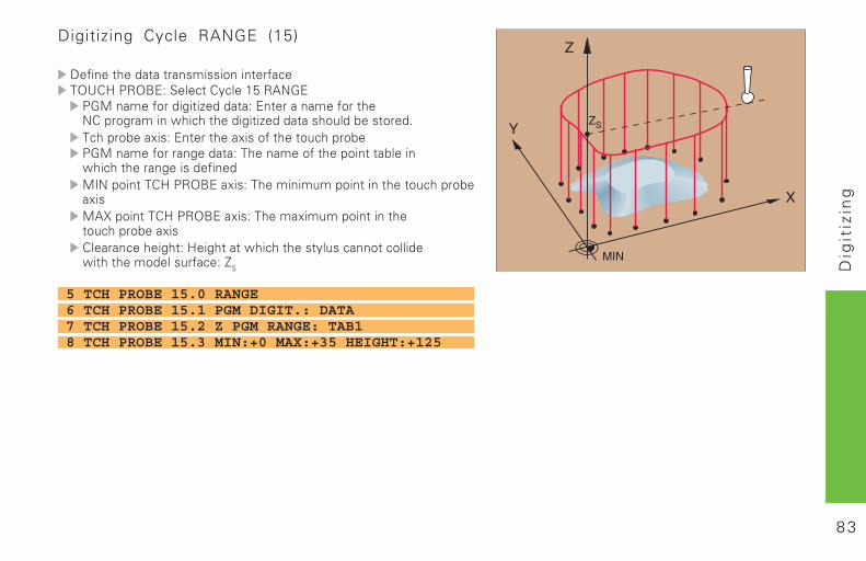
)���������������������������������".��� !"#$��1������������(%�!&�'$ '+����������������������$������������������������������������������������������� ����������3����������������$���������������������� �������� '+��������������������������������������������������������������������+0����������� !"#$��������������� ��������������� ������������+&4���������� !"#$���������������� �������������� ������������������������������������������������������ ���������������������������� �������7
�
5 TCH PROBE 15.0 RANGE6 TCH PROBE 15.1 PGM DIGIT.: DATA7 TCH PROBE 15.2 Z PGM RANGE: TAB18 TCH PROBE 15.3 MIN:+0 MAX:+35 HEIGHT:+125
8 4
Dig
itiz
ing
������ ��� � ���� �������������������� � ������ �����
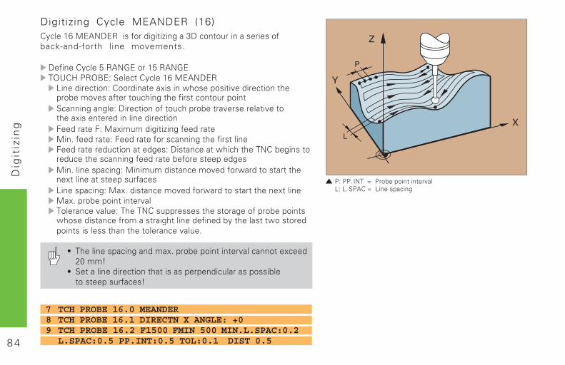
Digitizing Cycle MEANDER (16)������(*�+$&�)$!��������������������8)����� ���������������back-and-forth line movements3
)�����������%�!&�'$����(%�!&�'$�".��� !"#$��1������������(*�+$&�)$!/����������������������������������������,���������������������,����������� ������������������� ������1�����������)������������� ������������,�����������,��������������������������������������������+���� �������������������+�3������������������������������������������������������ ��������������)���������������������������������� ���������������������������������������+�3�������������+��� �����������,��������������������������������������� ������/�����������+��3����������,�����������������������������+��3����������������,�����������,�� ������������ �����������������������������������������������������������������������������������������������������������������������������,�� �3
� ��������������������3����������������,�������������9:����
� 1����������������������������������� ������������������������� �������
7 TCH PROBE 16.0 MEANDER8 TCH PROBE 16.1 DIRECTN X ANGLE: +09 TCH PROBE 16.2 F1500 FMIN 500 MIN.L.SPAC:0.2
L.SPAC:0.5 PP.INT:0.5 TOL:0.1 DIST 0.5
8 5
Dig
itiz
ing
������ ��� � ���� �������������������� � ������ �����
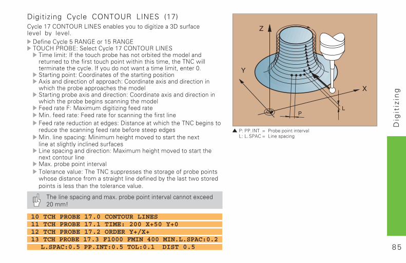
Digitizing Cycle CONTOUR LINES (17)������(-��"��".!�/0�$1���������� ��������������8)�� �����level by level3)�����������%�!&�'$����(%�!&�'$�".��� !"#$��1������������(-��"��".!�/0�$1������������0�������� ������������������������������������ ������������������ �����������������������5�������������������������������3�0���� ����������������������5������:31���������������������������������������������&���������������������������������������������������������������������������������������1������������������������������������������������������������������������������������������������������+���� �������������������+�3������������������������������������������������������ ��������������)���������������������������������� ���������������������������������������+�3�������������+��� �����������,����������������������������������������� ������/���������������������+���� �����������,���������������������� �����+��3����������������,�����������,�� ������������ �����������������������������������������������������������������������������������������������������������������������������,�� �3
��������������������3����������������,�������������9:����
10 TCH PROBE 17.0 CONTOUR LINES11 TCH PROBE 17.1 TIME: 200 X+50 Y+012 TCH PROBE 17.2 ORDER Y+/X+13 TCH PROBE 17.3 F1000 FMIN 400 MIN.L.SPAC:0.2 L.SPAC:0.5 PP.INT:0.5 TOL:0.1 DIST 0.5
8 6
Dig
itiz
ing
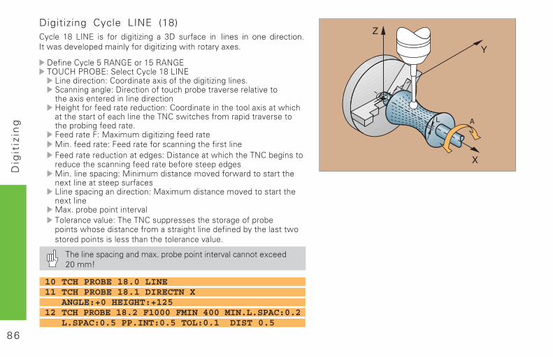
Digitizing Cycle LINE (18)������ (2� /0�$� ��� ���� ��������� �� 8)� � ������ �� lines in one direction30�������,�����������������������������������������3
)�����������%�!&�'$����(%�!&�'$�".��� !"#$��1������������(2�/0�$/����������������������������������������������31�����������)������������� ������������,�����������,������������������������������������������������������ ����������������������������������������������������������������������������������������������,��������������������������3������������+���� �������������������+�3������������������������������������������������������ ��������������)���������������������������������� ���������������������������������������+�3�������������+��� �����������,��������������������������������������� ������/����������������������+���� �����������,���������������������+��3����������������,�����������,�� ������������ �����������������������������������������������������������������������������������������������������������������������������,�� �3
��������������������3����������������,�������������9:����
10 TCH PROBE 18.0 LINE11 TCH PROBE 18.1 DIRECTN X ANGLE:+0 HEIGHT:+12512 TCH PROBE 18.2 F1000 FMIN 400 MIN.L.SPAC:0.2 L.SPAC:0.5 PP.INT:0.5 TOL:0.1 DIST 0.5
8 7
Gra
ph
ics
and
Sta
tus
Dis
pla
ys
Graphics and Status Displays
������������� �����������������
Defining the Workpiece in the Graphic Window����������������������������� !����������������������"� �#��������������� �"�������������$
%�������� �"�����������&������������������� ����������&��������������'��������� !�� �����(�!)*�� ��!+,��� �
��������" ������������� �������-�� ���� �������� ��� �$
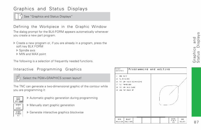
Interactive Programming Graphics
����������.�!/� +.0)%������� �������1
����*%��� ��� ���������"����� �� ����������������� �����"������������������ ���2
+���������������� ����� ���� ���������� �
!� �������������������� �����
�� ������ ������#���������3���'"��
8 8
Gra
ph
ics
and
Sta
tus
Dis
pla
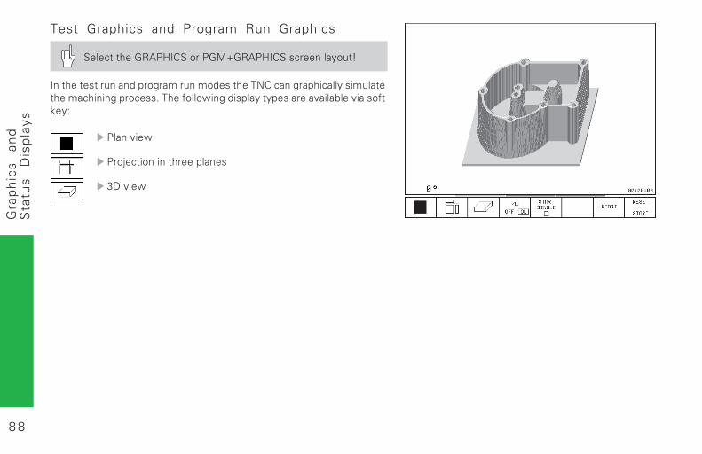
ysTest Graphics and Program Run Graphics
����������� +.0)%�����.�!/� +.0)%������� �������1
) ����������� �� ������������ �����������*%��� ������������������������ ���������$���������" ��������������������#���3���#������'��2
.�� �#�"
.��4���� � ��������� ��
5��#�"
8 9
Gra
ph
ics
and
Sta
tus
Dis
pla
ys
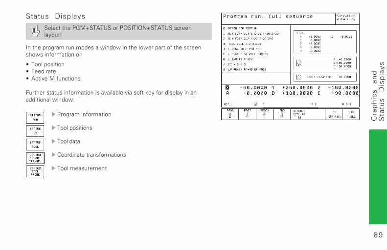
Status Displays
����������.�!/��+�6�����.��)�)�*/��+�6������� ������1
) �������������� ���������" ��"� ������"������������������� ��"�� ������� ��
7 ���������� 7 ���������7 +��#��!��� ��� �
�������������� ������� ����#���3���#�������'�������������� �� ����� ���" ��"2
.������� �������
���������� �
���������
%���� ������� �������� �
�������������� �
9 0
ISO
P
rog
ram
min
g
*) Effective blockwise
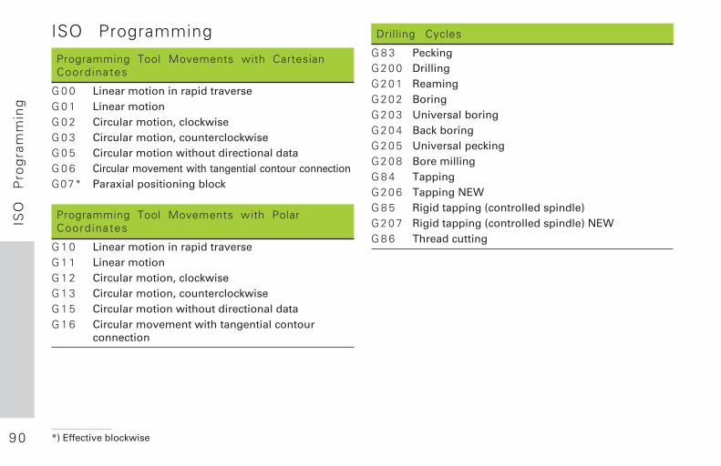
ISO Programming
Programming Tool Movements with CartesianCoord inates
G 0 0 Linear motion in rapid traverseG 0 1 Linear motionG 0 2 Circular motion, clockwiseG 0 3 Circular motion, counterclockwiseG 0 5 Circular motion without directional dataG 0 6 Circular movement with tangential contour connectionG07* Paraxial positioning block
Programming Tool Movements with PolarCoord inates
G 1 0 Linear motion in rapid traverseG 1 1 Linear motionG 1 2 Circular motion, clockwiseG 1 3 Circular motion, counterclockwiseG 1 5 Circular motion without directional dataG 1 6 Circular movement with tangential contour
connection
Drilling Cycles
G 8 3 PeckingG 2 0 0 DrillingG 2 0 1 ReamingG 2 0 2 BoringG 2 0 3 Universal boringG 2 0 4 Back boringG 2 0 5 Universal peckingG 2 0 8 Bore millingG 8 4 TappingG 2 0 6 Tapping NEWG 8 5 Rigid tapping (controlled spindle)G 2 0 7 Rigid tapping (controlled spindle) NEWG 8 6 Thread cutting
9 1
ISO
P
rog
ram
min
g
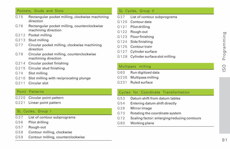
Pockets, Studs and Slots
G 7 5 Rectangular pocket milling, clockwise machiningdirection
G 7 6 Rectangular pocket milling, counterclockwisemachining direction
G 2 1 2 Pocket millingG 2 1 3 Stud millingG 7 7 Circular pocket milling, clockwise machining
directionG 7 8 Circular pocket milling, counterclockwise
machining directionG 2 1 4 Circular pocket finishingG 2 1 5 Circular stud finishingG 7 4 Slot millingG 2 1 0 Slot milling with reciprocating plungeG 2 1 1 Circular slot
Point Patterns
G 2 2 0 Circular point patternG 2 2 1 Linear point pattern
SL Cycles, Group I
G 3 7 List of contour subprogramsG 5 6 Pilot drillingG 5 7 Rough-outG 5 8 Contour milling, clockwiseG 5 9 Contour milling, counterclockwise
SL Cycles, Group II
G 3 7 List of contour subprogramsG120 Contour dataG121 Pilot drillingG122 Rough-outG123 Floor finishingG124 Side finishingG125 Contour trainG127 Cylinder surfaceG 1 2 8 Cylinder surface slot milling
Multipass milling
G 6 0 Run digitized dataG230 Multipass millingG231 Ruled surface
Cycles for Coordinate Transformation
G 5 3 Datum shift from datum tablesG 5 4 Entering datum shift directlyG 2 8 Mirror imageG 7 3 Rotating the coordinate systemG 7 2 Scaling factor: enlarging/reducing contoursG 8 0 Working plane
9 2
ISO
P
rog
ram
min
g
*) Effective blockwise
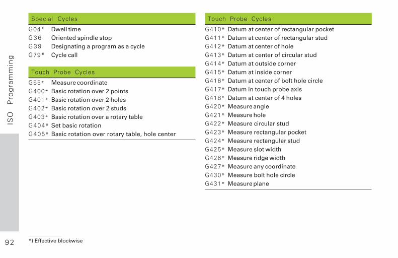
Special Cycles
G04* Dwell timeG 3 6 Oriented spindle stopG 3 9 Designating a program as a cycleG79* Cycle call
Touch Probe Cycles
G55* Measure coordinateG400* Basic rotation over 2 pointsG401* Basic rotation over 2 holesG402* Basic rotation over 2 studsG403* Basic rotation over a rotary tableG404* Set basic rotationG405* Basic rotation over rotary table, hole center
Touch Probe Cycles
G410* Datum at center of rectangular pocketG411* Datum at center of rectangular studG412* Datum at center of holeG413* Datum at center of circular studG414* Datum at outside cornerG415* Datum at inside cornerG416* Datum at center of bolt hole circleG417* Datum in touch probe axisG418* Datum at center of 4 holesG420* Measure angleG421* Measure holeG422* Measure circular studG423* Measure rectangular pocketG424* Measure rectangular studG425* Measure slot widthG426* Measure ridge widthG427* Measure any coordinateG430* Measure bolt hole circleG431* Measure plane
9 3
ISO
P
rog
ram
min
g
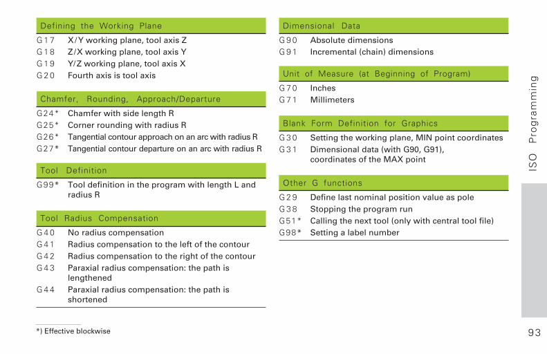
Defining the Working Plane
G 1 7 X/Y working plane, tool axis ZG 1 8 Z/X working plane, tool axis YG 1 9 Y/Z working plane, tool axis XG 2 0 Fourth axis is tool axis
Chamfer, Rounding, Approach/Departure
G24* Chamfer with side length RG25* Corner rounding with radius RG26* Tangential contour approach on an arc with radius RG27* Tangential contour departure on an arc with radius R
Tool Definition
G99* Tool definition in the program with length L andradius R
Tool Radius Compensation
G 4 0 No radius compensationG 4 1 Radius compensation to the left of the contourG 4 2 Radius compensation to the right of the contourG 4 3 Paraxial radius compensation: the path is
lengthenedG 4 4 Paraxial radius compensation: the path is
shortened
Dimensional Data
G 9 0 Absolute dimensionsG 9 1 Incremental (chain) dimensions
Unit of Measure (at Beginning of Program)
G 7 0 InchesG 7 1 Millimeters
Blank Form Definition for Graphics
G 3 0 Setting the working plane, MIN point coordinatesG 3 1 Dimensional data (with G90, G91),
coordinates of the MAX point
Other G functions
G 2 9 Define last nominal position value as poleG 3 8 Stopping the program runG51* Calling the next tool (only with central tool file)G98* Setting a label number
*) Effective blockwise
9 4
ISO
P
rog
ram
min
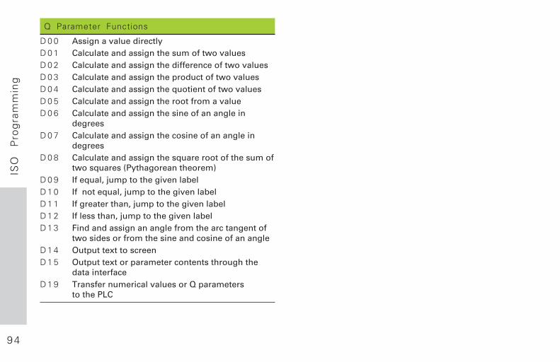
gQ Parameter Functions
D 0 0 Assign a value directlyD 0 1 Calculate and assign the sum of two valuesD 0 2 Calculate and assign the difference of two valuesD 0 3 Calculate and assign the product of two valuesD 0 4 Calculate and assign the quotient of two valuesD 0 5 Calculate and assign the root from a valueD 0 6 Calculate and assign the sine of an angle in
degreesD 0 7 Calculate and assign the cosine of an angle in
degreesD 0 8 Calculate and assign the square root of the sum of
two squares (Pythagorean theorem)D 0 9 If equal, jump to the given labelD 1 0 If not equal, jump to the given labelD 1 1 If greater than, jump to the given labelD 1 2 If less than, jump to the given labelD 1 3 Find and assign an angle from the arc tangent of
two sides or from the sine and cosine of an angleD 1 4 Output text to screenD 1 5 Output text or parameter contents through the
data interfaceD 1 9 Transfer numerical values or Q parameters
to the PLC
9 5
ISO
P
rog
ram
min
g
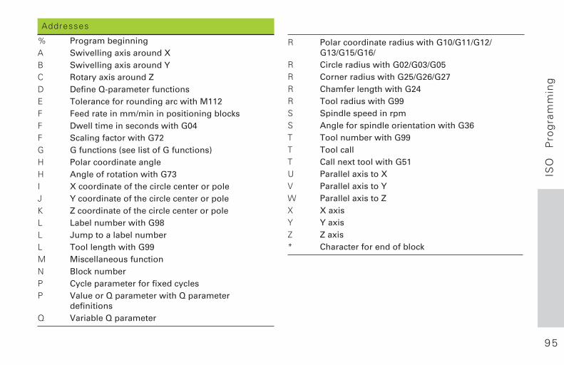
Addresses
% Program beginningA Swivelling axis around XB Swivelling axis around YC Rotary axis around ZD Define Q-parameter functionsE Tolerance for rounding arc with M112F Feed rate in mm/min in positioning blocksF Dwell time in seconds with G04F Scaling factor with G72G G functions (see list of G functions)H Polar coordinate angleH Angle of rotation with G73I X coordinate of the circle center or poleJ Y coordinate of the circle center or poleK Z coordinate of the circle center or poleL Label number with G98L Jump to a label numberL Tool length with G99M Miscellaneous functionN Block numberP Cycle parameter for fixed cyclesP Value or Q parameter with Q parameter
definitionsQ Variable Q parameter
R Polar coordinate radius with G10/G11/G12/G13/G15/G16/
R Circle radius with G02/G03/G05R Corner radius with G25/G26/G27R Chamfer length with G24R Tool radius with G99S Spindle speed in rpmS Angle for spindle orientation with G36T Tool number with G99T Tool callT Call next tool with G51U Parallel axis to XV Parallel axis to YW Parallel axis to ZX X axisY Y axisZ Z axis* Character for end of block
9 6
Mis
cella
ne
ou
s F
un
ctio
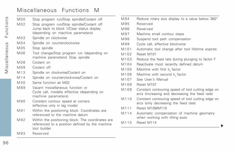
ns M94 Reduce rotary axis display to a value below 360°
M95 ReservedM96 ReservedM97 Machine small contour stepsM98 Suspend tool path compensationM99 Cycle call, effective blockwiseM101 Automatic tool change after tool lifetime expiresM102 Reset M101M103 Reduce the feed rate during plunging to factor FM104 Reactivate most recently defined datumM105 Machine with first kV factorM106 Machine with second kV factorM107 See User's ManualM108 Reset M107M109 Constant contouring speed of tool cutting edge on
arcs (increasing and decreasing the feed rate)M110 Constant contouring speed of tool cutting edge on
arcs (only decreasing the feed rate)M111 Reset M109/M110M114 Automatic compensation of machine geometry
when working with tilting axesM115 Reset M114
Miscellaneous Functions M
M00 Stop program run/Stop spindle/Coolant offM02 Stop program run/Stop spindle/Coolant off
Jump back to block 1/Clear status display(depending on machine parameters)
M03 Spindle on clockwiseM04 Spindle on counterclockwiseM05 Stop spindleM06 Tool change/Stop program run (depending on
machine parameters) Stop spindleM08 Coolant onM09 Coolant offM13 Spindle on clockwise/Coolant onM14 Spindle on counterclockwise/Coolant onM30 Same function as M02M89 Vacant miscellaneous function or
Cycle call, modally effective (depending onmachine parameters)
M90 Constant contour speed at corners(effective only in lag mode)
M91 Within the positioning block: Coordinates arereferenced to the machine datum
M92 Within the positioning block: The coordinates arereferenced to a position defined by the machinetool builder
M93 Reserved
9 7
Mis
cella
ne
ou
s F
un
ctio
ns
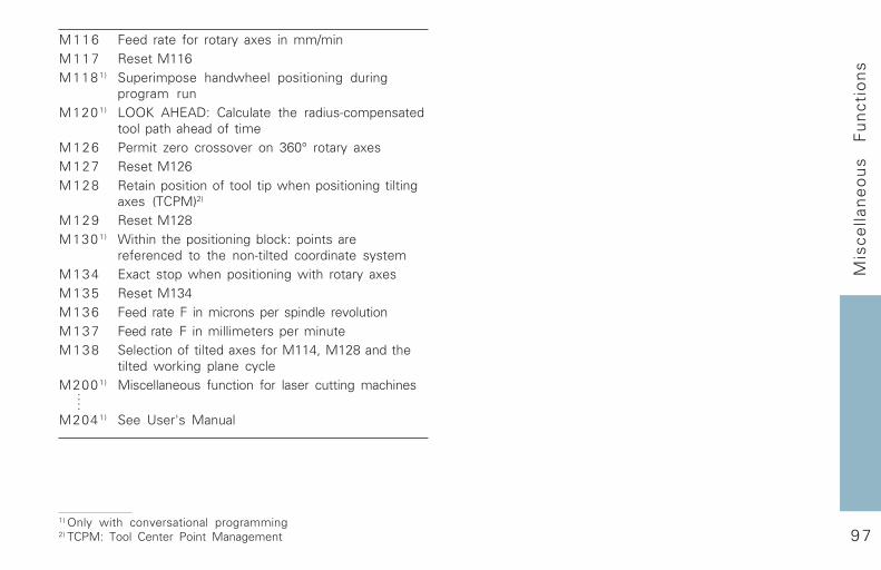
1) Only with conversational programming2) TCPM: Tool Center Point Management
M116 Feed rate for rotary axes in mm/minM117 Reset M116M1181) Superimpose handwheel positioning during
program runM1201) LOOK AHEAD: Calculate the radius-compensated
tool path ahead of timeM126 Permit zero crossover on 360° rotary axesM127 Reset M126M128 Retain position of tool tip when positioning tilting
axes (TCPM)2)
M129 Reset M128M1301) Within the positioning block: points are
referenced to the non-tilted coordinate systemM134 Exact stop when positioning with rotary axesM135 Reset M134M136 Feed rate F in microns per spindle revolutionM137 Feed rate F in millimeters per minuteM138 Selection of tilted axes for M114, M128 and the
tilted working plane cycleM2001) Miscellaneous function for laser cutting machines
M2041) See User's Manual
....

������������ ��� ��������������� ��������������������������������������� ���������������� ����������������� �!"��#�$����������
����� ��!�"�##$�� � �������������������� �!"����%�&�$����������
%��"�� �&�"�"���" � �������������������� �!"����%�&��'���())���$����������
�'�"�##$�� � �������������������� �!"����%�&��&��())���$����������
'�#�$&���� �& � �������������������� �!"����%�&��&�)*'$����������
()'�#�$&���� �& � �����������������+�� �!"����%�&��)!&$����������
)������$���$!" � �����,������+������� �!"����%�&����#$����������
***��� +���� ��+�
Ve 02322 441-22 · SW14 · 11/99 · pdf · Subject to change without notice