Embed Size (px)
Citation preview

1.A-72.370-MS
UC-706ati[iUC-721/!;s1{1’1/:S1’pl’ttliw” 199.3
“f//llh”ll .%11”. .1/)”/“lJ,”l”(’.Illllhwu,%ldhruil.+fl/iliSlllU. fh’/WflWIW/ Ill / Il;;llh”to)lll::MI”I IMIIII’>II(J llSAFAll~FEM. }“tfirihild Ihll,(-,t/t,r,l,f(t Sltrjrl,.:.. C( ) S11S.1[).
LosAlarms)/ATIO NAI !ABCR ATORY
LosAlamos. New Mexico 87545%/
01STl<iiKJT10f4OF THISDOCUMENT ISUNLIMITEO

THE POTENTIAL OF CENTRIFUGAL CASTINGFOR THE PRODUCTION OF NEAR NET SHAPE URANIUM PARTS
by
Erica Robertson
1 :\B3T&%.”’I’
This report was written to provide a detailedsummary of a literature survey on ‘the near net shapecasting process of centrifugal casting. Centrifugalcasting is one potential casting method which couldsatisfy the requirements of the LANL program titled NearNet Shape Casting of Uranilm for Reduced Environmental,Safety and Health Impact. In this report, centrifugalcasting techniques are reviewed and an assessment of theability to achieve the near net shape and wasteminimization goals of the LANL program by using thesetechniques is made. Based upon the literature reviewed,it is concluded that if properly modified for operationwithin a vacuum, vertical or horizontal centrifugationcould be used to safely cast uranium for the productionof hollow, cylindrical parts. However, for theproduction of components of geometries other than hollowtubes, vertical centrifugation could be combined withother casting methods such as semi-permanent mold orinvestment casting.
1. INTRODUCTION
The purpose of this report is to describe centrifugal casting
practices and to determine the viability of using these techniques
to achieve near net shape uranium and uranium alloy products which
minimize hazardous waste generation. A general description of thecentrifugal casting process is given followed by a discussion of
the different types of centrifugal casting machines, the product
forms most often manufactured by centrifugal casting technique:,
some specific advantages of centrifugal casting methods, thecombination of centrifugal force with other casting processes, and
a summary of research findings on the relationships between various
process parameters and final product properties based upon
1

experimentation and validation of
This report is concluded with a
centrifugal casting techniques
models with
section on
to achieve
experimental results.
the potential use of
near net shapes and
subsequent hazardous waste minimization when casting uranium or
uranium alloys.
II. PROCESS DEFINITION
Centrifugal casting is ~ casting process in which molten metal
is poured into a rapidly rotating mold. The centrifugal force due
to Lotation causes the molten metal to be spread over the mold
surface such ttl~ta hollow, cylindrical type casting is producedafter complete solidification. The axis of mold rotat:on may be
either vertical ok-hol-izontal. In either case, the centrifugalforce causes high pressuces to develop in the metal as it freezes
with directional solidification, helps in metal feeding andcontributes to the removal of non--metallicinclusions and evolved
gases toward tileinner ~:ll~-faceOf the kliow casting.
Although the centrifugal technique is used primarily for the
production of hollow components, there ha:e been occasions when theuse of centrifugal action was used to create solid parts.;
:;~wever, this is most often found when centrifugal force is
combined with <lnothercasting technique such as investment casting.
This specialized use of cent~ifuga.1action will be discussed in a
-er section of this report.......
III. CENTRIFUGAL CASTING MACHINES AND THEIR PRODUCT FORMS%
A. Flanqed Shaft Machine
This type of machine
on a flange as an overhung
(Fig. I)L supports a mold horizontally
load. Horizontal mold orientations are
usually used for castings which are sufficiently long, i.e.
length/diameter ratios > 1.5. The flarlgedshaft machine is used to
2

make all forms of flanges, ring-type castings and general
cylindrical shapes but is most often used to m~ke short tubes for
cylinder linerj, bushes, sleeves, tubes to be cut into rings, gear-
wheel blanks, piston and bearing cage uings. Castirlgweight is’limited to less than one ton.
g. Horizontal Machine (Roller TYRe)
This machine (Fig. 2); is used to make tubular castingsusually where production quantities are high. It is not the same
as the pipe casting machine. The horizontally rotated mold is
composed of four parts: 1) the shell, 2) t-hecasting s~out (the
end of the mold into which the molten metal i~ poured), 3) the
roller tracks and 4) the two end heads. The mold usually lies on
fouL- interchangeable carrying rollel-s which are capable of
providing good contact becween different sizes of mold diameters
and the roller tracks. As the mold is.rotated, it is also cooled
with a controlled water spray system. With the horizontal
centrifugation technique, castings up to 8 m long, 30 tons in
weight, up to 1000 mm in diameter, as well as tubes up to 5 m long
for all diameters down to 75 mm, in most alloys, have been made.
c. Double-Face Plate Machine
This is another horizontal machine (Fig. 3)- which was
originally develop~d co line bearing shells with white metal. In
chis technique, simple cylindrical molds of steel or cast-iron are
clamped between the two face plates and the pouring operation takes
place through one of the bearings supporting the face plate. When
the casting operation is finished, the cylindrical mold, together
with the casting, is removed from the machine for casting
extraction.

,.,., ,!..,, .,. . .. ... ,.
. ,., ,
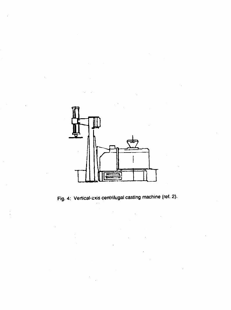
D. Vertical-Axis Centrifugal Castinq itiachine
In this machine, (Fig. 4)’ molds are oriented vertically,
either attached to a face plate or to the flange of a vertical
shaft. The vertical mold orientation is usually used when the
diameter of the c~s~ing is greater than its length or the
length/diameter ratio < 1.5. However, Pfeifer and Moak4 modified
this technique to produce a misch-metal integral liner in the
standard 105 mm projectile. Small machines are used at floor level
til~dt~~eused mainly to make qear-wheel bl~,nks,flanges and bushes.
For larger and heavier castings (>200 tons), machines are usrdlly
pla:ed below floor ievel. This is the te ;...LcqueInostoften used
for fiidkingIoli]l,qmii; rolls.
the ba: :).
The ot:ierdifference be~ween Lj~et~.tiomold orient aLions is the
speed obtained by the molten I,’eta1 ‘3s it is :swir1d around the
~iol d. W)__:‘-nmolten m%a 1 is poured into the horizontu1ly rotatirig
mold, .:onsidel”ableS1ip occurs between the metal un~ the mold such
tiic:‘“ the metal does mot move as fast as che rotating mold. To
overcome this inertia, the metal must be accelerated to reach the
mold rotation speed. This is not a problem in the vertical
centrifugation process where the molten metal reaches the speed of
4

t!:emold soon after pouring. However, wit)~a vertical mold axis,there is a tendency for the moltel metal to form a parabolic shaped
bore due to the competing gravitational and centrifugal forces
acting on the molten metal.
v. ADVANTAGES OF THE CENTRIFUGAL CASTING METHODS
“The following is a list
casting process often cited in
1. The centrifugal action
and gases thus yielding a
of advantages of the centrifugal
the literature:l”~’G’7
removes unwanted inclusions, dross,cleaner casting.
2. Castings are free from any form of shrinkage because the
material that contains the shrinkage is rnachirledaway (e.g.
boring out the center to make tubes).
3. Mechanical properties are often superior to those of
static castings due to the finer grains resulting from the
process which are of constant size in circumferential and
axial directions.
4. Due to cleanliness and finer grain size, good weldability
is achie-~ed.
5. A 100% design factor can be used with the advantages of
less metal beinq required which generates a cost saving.
6. Class I castings can be produced without the need for
upgrading and costly weld repairs.
7. The flexibility of the process allows 4 inch to 120 inch
diameters to be cast and lengths from a few inches to 16 ft
depending on the machine selected. And, with the use ofrefractory ceramic molds, complex outer part profiles may be
K

cast.
VI. DEFECTS IN CENTRIFUGAL CASTINGS
The three most common defects observed in centrifugal castings
are segregation banding, raining and vibration defects.~Segregation banding can occur in both horizontal and verticalcentrifugally cast parts, but usually is only found in castings
with wall thicknesses greater thaxi50 to 75 mm ( 2 to 3 in.). Thebands that can occur are annular segregated zones of low melting
constituents. Banding is more prevalent in alloys with ,a widesolidification range and greater solidification shrinkage. Bandinghas also been as’s’oci~tedwith a critical level of mold rotation
speed as well as with low rotational speeds. However, there are no
“definitive answers abo~lt what facto~~ contribute t. banding.
Several theories have been p~oposed to explain this phenomenon
which include the effect of vibration, variation in gravitational“force,and ii-regularitiesillmetal flo~vo
Raining is a phenomenon that occurs in horizontal centrifugal
castings. If the mold is rotated at too low a
metal is poured into the mold tuo fast, the metal
falls from the top of the mold to the bottom.
control can eiifi~inateraining and thereby ensure
a cascir,g w~.tha ‘Jniforrnstructul”e.
speed or if the
actually rains or
Proper process
the formation of
Vibracion can lead to defects in centrifugal castings ,whlch
manifest themselves as laminations in the castings. This problemcan often be overcome by minimizing vibrations affecting the
casting equipment; e.g. ensuring proper
of the molds, and frequent inspections
casting machine.
mounting, careful balancing
of other vital parts of the
6

VII. THE
METHODS
COMBINATION OF CENTRIFUGAL FORCE WITH OTHER CASTING
A . Cel!trifuqalForce and Investment Castinq
When the action of centrifugal force is ccmbined with
investment casting, the main benefit is an ilnprovementin casting
soundness with subsequent improvements in mechanical properties.
In an article by Lee and Yun”, the influence of centrifugal force
upon aluminum investment castings was explored. They found that 1)
a down-tapered sprue was more effective in eliminating turbulence
of the metal stream and non metallic incisions, 2) surface
smoothness and dimensional accuracy of Ai-alloy centrifugal
castings were much better than the gl-avityinvestment castings, but
they were much more affected by the fineness of investment material
than centrifugal force, and 3) the soundness and mechanical
properties were improved with increased centrifugal force.
A more detailed study by Osinskii et al. discusses the
importance of the liquidus-solidus interval degree range on
solidification in centrifugally cast ivestment mold castings.]”
This work also investigated the quantitative relationships between
the ‘technological production” conditions and the gating system
dimensions in relation to final casting soundness in ‘castings of
alloys with narrow and wide freezing ranges. Factors which
influenced the casting sounaness were identified as:
1.
2.
3.
4.
5.
6.
7.
8.
ingate diameter, d
sprue diameter, D
metal pour temperature
moid temperature prior to pour
mold speed, n
spinning period
casting weight (expressed as a castings length, 1)
the number, N, of castings in each ring on the sprue
7
9. the distance, L, from the axis of rotati into the castings
on the sprue (which characterizes the sprue length)
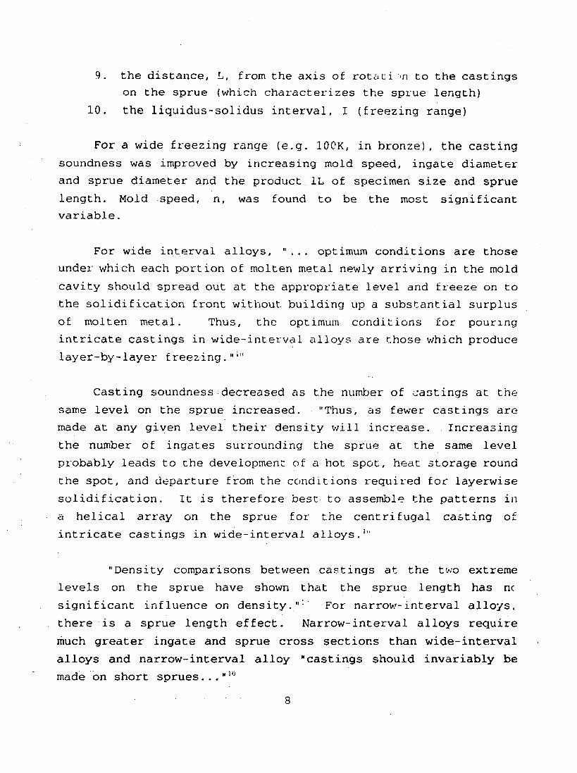
10. the liquidus-solidus interval, I (freezing range)
For a wide freezing range (e.g. 1OCK, in bronze), the casting
soundness was improved by increasing mold speed, ingate diameter
and sprue diameter and the product,IL of specimen size and sprue
length. Mold speed, n, was found to be the most significant
variable.
For wide interval alloys, “... optimum conditions are those
under which each portion of molten metal newly arriving in the mold
cavity should spread out at the appropriate level and freeze on to
the solidification front without building up a substantial surPluS
of molten metal. Thus, the optimum conditions for pouring
intricate castings in wide-interval alloys are
layer-by-layer freezing.’’ti’
Casting soundnessdecreased as the number
same level on the sprue increased. “Thus, as
those which produce
of castings at the
fewer castings are
made at any given level their density will increase. Increasing
the number of ingates surrounding the sprue at the same level
probably leads to the development of a hot spot, heat storage round
the spot, and departure from the ccjnditionsrequired for layerwise
solidification. It is therefore best to assemble the patterns in
a helical array on the sprue for
intricate castings in wide-interval
“Density comparisons between
the centrifugal casting of
alloys.1”
castings at the tww extreme
levels on the sprue have shown that the sprue length has n(
significant influence on density.”;’ For narrow-interval alloys,.
there is a sprue length effect. Narrow-interval alloys require
much greater ingate and sprue cross sections than wide-interval
alloys and narrow-interval alloy “castings should invariably be.—made “on short sprues...“1°
8

The authors conclude with two summary paragraphs and state
that their recmrmendations have been verified in the production cf
steel castings with different liquidus-solidus intervals:
“Narrow-intervalalloys require heat accumulation around
the sprue and ingates. Sound castings can be made byaccumulating surplus molten metal ahead of the solidification
front. In this case, the optimum conditions correspond to
wide-section ingates and sprues, mold pr~h~a~ing, the use of
short sprues and some reduction in the relative rate of molten
metal supply to the mold cavities.:’
“Intricate castings in wide-interval alloys must be
under conditions which will prevent excessive
made
heataccumulation round the gating system and mold cavities and
minimize the volume Gf mol~en metal ahead of the
solidification front. Sound metal can be ensured bydirectional solidification. In this case, mold pre-heating,
commensurate metal weights and sprue lengths, helical mold
assemblies round the sprue ana normal ingate and sprue cross
sections should lead to a certain ‘freezing’ action, while
rapid molcicavity filling with metal in this condition should
lead to layerwise solidific~tion.”:
B. Centrifugal Force Combined wich Electroslaq Castinq
A process called centrifugal e.le,ctroslagcasting was developed
at the E.O. Paton Welding Insticute, Academy of Sciences of the
Ukranian SSR; Kiev.:: In this process, liquid metal fromelectroslag melting is collected in a lined refractory crucible and
poured intl~a horizontally rotating mold together with slag used
for remelting. This method is used for the production of “billetsU
in the shapes of rings, sleeves or pipes which replace forgings in
various components.
9

The authors set out to detel”mine the optimum casting
parameters which wculd ensure maximum mechanical properties of the
centrifugal electroslag blanks. The authors noted that ‘The amount
l)f infol-mationof the CESC process accumulated as a result of
r.heoretical examination, physical modeling and analysis of
~]~eliminaryexperiments was insufficient for considering the effect
~L the individual technological factors and, in particular, the
,?ffect of their interaction ~n the service properties of the
,:dstings.““ The authors therefore invoked the theory of extreme
.~pcrirnentswhich “makes it possible to solve the problem of
imising technology and examine the properties of resultin9,.?.idls even if the data on the process is [sic] incomplete.“‘“
.r.,-1upon this theory, the method of random balance, computer
programs which yielded a five-factor regression equation for the
‘ESCprocess and their experimental results, the,authors concluded
~i~t the strongest effect on the qua~ity of the castings is exerted
:Lrthe temperature of the metal yflaredinto the mold a;ldby the
tate of metal feed into the mold. They Jiso CbSf3L_V~d a correlation
between the speed of rotation and the mass (wall thickness) of the
casting which showed that the effect of the speed of rotation of
the mold on the quality of the casting became stronger
increase of its wall thickiless.
\!III. MODE~,I1.j~~~.~JDExperimental RESE.~RCHON CENTRIFUGAL
with the
CASTING
A ver}-et~!”l>~attempt to model tilecentrifugal casting prOCeSS
was m~de by S.L. Conner in the early 1930’s.:- An effort was made
to mcdel the thermal contours in the casting mold used to produce
castings of the gun barrels for the U.S. Army’s 75 mm Pack
Howitzers. !3Ut, in the author’s own words, “the results were
approximations dt best based on assumptions that were not
necessarily correct.”; Although the degree of sophistication
involved in this early modeling attempt may have been lacking, it
was adequate for its intended purpose. Between 1932 and 1935, this
work enabled centrifugal casting to,evolve from an experimental
10
—

In 1970, J . Jez 1e~sk i pel”tal-I[lI:Ci~[1 expel iIner,r u 1Hleu ,3c
determining the facto~s which lead to i[lcre<,sed centLifugal ~sasLir~(j
mold 1ife by mocle1ing rhe tempera cure gL-aciien rs in .3 mb 1d .3n~:
comparing the results with experiment 1 data . T1~ Lhis 5tUdy,
temperd tuL-e gradien ts were de rermi ned fl-on] therrnocoup 1e
measurements o f the Cempel”atul’e~ Gf the out~~” al]d irlrlel rr,oIu
surfdces du K“inq c’ent~ifuqa 1 cd stiIlg o t Cc-lstilorltubing. ~>,
ga inlng a bet Ler uncle~standi~lg ‘of tlle theL-ma1 gLadi ents iI: & mol ~i
and the ~-esu1ting the~”ma1 stress states, the jegree of mold pre-
heating necessary to extend mo lci 1ite by minimizing therma 1 shock
effQC ts was de”tez-minecl.
Iri1933, the therrna1 dspects o f ho l-izont it1 CeIIrLifugti.1casting
weL-e e:<p1Ored at the I?esearch Ce,~tre of PonL-a-Mcus son S .A. i:~
France us .ing a se.mi-indus tL-ia1 sized iIIStIument ed c~s ting maclIine . ‘
The emphasis CJf this wo~-k wds the det erminat ion o f which casting
parameters most in f1uence the Cemperature histoL-y during
solidificdtion of a cast tube of a Mn-Ni-Me-Nb dispersoid steel, or
Centrishore V, u we1dable high-strength stee1 with good impact
resistance at low temperatures ,used to manufacture 1~rge sized
heavy-wal1 pipes for offshore oi1 constructions.
This pilot centrifugal spinning m~chine cou1d be, us,ed to
measure t.he temperature inside the rotating mo1d and on th.einner
surface of the tube during solidification. This was possible
because the mold was eq(lipped with a telemetering device, a
balancing system to ensure regular and uniform rotation Gf the
mold, 6 thermocouples placed at different levels in the mold
section, a fixed receiving aerial.fastened under the machine frame
and a receiving set connected to a ketching table to allow for
continuous monitoring “ofthe temperature profiles in the mold. In
addition, an optica1 pyrometer was used for measuring the inner
11

tube wall temperature.
Using this set-up, experimental and mathematical studies wereperformed to examine the influence of various parameters on the
thermal behavior of the cast tube and the mold in order to validate
a classical model of heat-trar,sferby conduction. The authorsconcluded that the parameters directly related to the mold itself
had almost no influence on the thermal solidification rate of the
steel. From evaluation of the temperature curves of ttlesteel
during solidification, the authors determined that the moldthickness, the mold thermal conductivity, the initicl temperature
of the mold, and the sprinkling flow used to cool the mold had a
very small and limited effect such that the metallurgical
parameters G/R and G.R were not affected.
In contrast, the factors exerting the strongest influence upon
solidification rates and final grain size were the casting
temperature and the thickness of the coating material sprayed in
the moid. For a high casting temperature, the size of the coarse
grain zone and Lhe average grain size were reduced with thinner
mold ..oatingthicknesses. For low casting temperatures, a decrease
in the :old coating thickness led to a decrease of the average
grain size but not to that of the size of the coarse grain zone.
In 1985, Y. Ebisu used different solution methods for thermo-
plastic plastic finite element analysis to analyze centrifugal
casting molds.*C The influence of the casting parameters on the
stress-strain state of the molds was then analyzed. It was
determined that the occurrence of mold warping or bowing decreased
considerably by increasing the thermal resistance of the mold
coating, by lowering the metal pour temperature and by thickening
the mold wall.
12
—

—
IX. CONSIDERATION IN THE APPLICATION OF CENTRIFUGAL CASTING TO
URANIUM AND URANIUM ALLOYS
Centrifuga1 casting, in general, is best suited to the
production of hollow, cylindrical parts. If it ~~eredesired toproduce .~uch a uranium or uranium alloy tube, vertical orhorizontal centrifugal casting could be a cost effective production
method to achieve this near net shape with the added benefit of
~.educedmachining waste generation and a cost savings. In fact,centrifugal casting of uranium has been performed by the French in
1968.:” It would be interesting and
~-~fe~.ence t.Lal]slated into English to
been done. In the meantime, to
cent~-ifllgal casting to uranium, the
be addressed:
perhaps valuable to have this
learn exactly what has already
consider the application of
following areas would need to
1) Selection of a machine with ~ vertical or horizontal mold
rotation d~is. This decision should be”based on the length to
diameter ratio as well as the production capabilities and
efficiencies of the chosen machine.
2J Consideration of castinq atmosphere. To minimize oxidationeffects, the selected centrifugal casting machine would need to be
able to operate in a vacuum. This would obviously necessitate the
elimination of the usual water sprinkling system used to cool the
molds. An alternative mechanism to provide mold cooling could be
the back-filling of che vacuum chamber with a circulated inert gas
such as argon or helium.
3) Selection of a suitable mold. Material selection andcompatibility issues would need to be addressed with emphasis on
material reactivity, thermal and mechanical properties. Otherconsiderations would be mold design and mold geometry (e.g. mold
thickness, mold coating selection, application and thickness).
13

4) Determination of metal pour ... - ture and mold ~re-heat
temperature. Experimental researc : shown that higher pourtemperatures result in more dense casc~~g~ with better mechanical
properties. Thus, the optimum temperatures for pouring uranium or
its alloys would need to be determined. If mold life is to beconsidered, determination of the optimum mold pre-heat temperature
would be useful to minimize the effects of thermal shock and
thermal fatigue.
5) Determination of metal feed rate, o~timum mold sReed andspinninq period. In order to achieve a layered directional
solidification effect, the freezing rana~ width must be considered
when casting an alloy. If the alloy has a wide freezing range, a
faster mold speed and slower metal feed rate will ensure that
excessive heat accumulation is avoided and the volume of metal
ahead of the solidification front is minimized. If the alloy hasa narrow freezing range, a slower mold speed and faster metal pour
rate would be needed to ensure that there is sufficient surplus
metal ahead of the solidification front.
In conclusion, the determination of which combination ofmaterial and casting parameters would provide the best casting
soundness and mechanical properties could be a lengthy and costly
process if an entirely experimental approach were selected. A more
cost-effective and time-effective approach would be to use computer
modeling of the casting process (considering such factors asmaterial properties, fluid flow and heat transfer) in conjunction
with experimentation to prove the validity of the model. By usingsuch an approach, the potential benefit of applying centrifugal
casting techniques to uraxiiumor uranium alloys, the production of’
near net shape, hollow, cylindricalparts at lower costs associated
with less final machining and less hazardous waste generation could
be realized. Also, vertical centrifugation could be combined with
another casting technique, such as investment.casting, to takeadvantage of centrifugal force when producing parts that are not
hollow tubes.14

x. ACKNOWLEDGEEMEI’JT!;
The author acknowledges ~}1~.:~i~~’t)~c.ei~ffic,.r,i:;;:i,<llciti::
Research fcr the position of Mi1itary Research As.sociate In the
MST-6 Group of Los .llanosNationa1 Label.atory.
XI. REFERENCES
1. L.J . Stefan et a1, “Research on Refractory Alloys of Tungsten,Tantalurn,Molybdenum, and Columbium,“ Thompson Ramo WooldridgetInc., Technica1 Documentary Report”NJr: ML T9R 64-271, (September1964).
2. D.S. Gibson, “Basic” Designs of Centrifugal Casting Machines,“Founc/l-yTrdde Journ~~, 156 (3278), 61-62, (Feb 2, 1984).
3. A. Royer, “The Horizontal Centrlfugation: A Technique cfFoundry Well Adapted to the Processing of High Reliability Pieces,“in Proceedings of the International Conference on Adv~nced CastingTech.nolCJgy,Ka1amazoo, M1, 12-14 November 1986. (1987), pp. 1-12.
4. W.H. Pfeifer and D.P. Moak, “CentI-ifugal Casting of Misch-MetalLiners for the 105 mm Projectile,“ Journal of Vacuum Science andTechnology, 11 (6), 1072-1083, (Nov/Dec 1974).
5. R.L. Kum~r and S.K. Dike, “Experiments on Centrifugal Castingof Aluminum in Horizontal and Vertical Axis Machines,” IndiafiFoundry Journal, 28 (l), 9-12, (Jan 1982).
6. !?. Nixon, “Advantages of Castings Produced by theCentrispinning Process,” Foundry Trade Journ~l, 161 (3352), 557-559, (z JUIY 1987).
7. B.14.Jones, “CentrifugalMolding and Casting,“ American Societyof Tool and Manufacturing Engineers Technical Paper #SP66-67, (Jan1966).
8. Metalsffankbook,9th ed., Volume 15, (ASM International, MetalsPark, OH, 1988), pp. 297-307.
9. Jong-Nam Lee and Gi-Cheon Yun, ‘Effect of Centrifugal ForceApplied During Investment Casting on the Soundness of Cast AlAlloys,“ Journal of the Korean Institute of Metals, 15 (2), 155-163, (1977) .
10. V.I. Osinskii, M.V. Solov’ev, and A.V. Morozov, “Soundness ofIntricate Centrifugally Cast Investment-Mold Castings,”(Translation) Soviet CastingsTechnology,7, 50-54, (1987).
15

11. V.v. Shakhov and V.L. Shevtsov, “Optimisatl(’[1 ofTechnological Parameters of Centrifugal Electroslag CaPtillgwiththe Horizontal Axis of Rotation,0 Prohlemy spt- ‘al‘noiElektormetallurgii, 3 (4), 35-3’7,(198’7).
12. S.L. Conner, “Operating Report, Centrifuge::’CastingEquipment,u Watertown Arsenal Report No. 613/131, (1 July 1935).
13. J.Jezierski,“Analysisof the Stateof The~malStressin MoldsDuring CentrifugalCasting,” AFS Cast Metals Research Journal, 6(2),75-79, (June 1970) .
14. S. Vasseur,R. Roll-Duchanoy,5. Metauer,C, Frantz,and M,Gantois, “Thermal, Metallurgical and ‘mechanicalA:~ects ofDispersoid CentrifugallyCast Steels,” in ‘proceedingsof theInternational Conference on Techno20q~ and A~plications of HSLASteels, Metals Park, OH, 3-6 octobe~ :983, American Society forMetals,pp. 1155-1169.
15. Y. Ebisu, “SolutionMethodsfor .le:~.u-clas~icPldsticFEM andIts Applicationto Centrifuc,lCast: .g Mold,U Tz-ansactions IL71J,25, 30-39, (1985).
16. Y. Orteland J. Vayra, “Cc! ri:ugalCasting of Uranium, ~ paperfrom Congres Internat sur les April.‘ations des Techniques du videa la Metallurgic 1968 Societe F .caise,94 Nogent/ Marne, 195-198,
16

. . .- —————-... .— —.——-. .——
,,
—
Fig. 1: Flangedshaftcentrifugalcastir,.jmachine(ref.2).
7.

.,
-L.—. -. * -– .– — —. ... -— —-
99z 1
Fig.2: Horizontal roller centrifugal casting machine (ref. 3).
(f}(2}(3}(4)(5)
-JdMl Jer crdckcast An9 spoutc~SCJQ~POt
.
...
,!,
—— —

I
Fig.3: Double-faceplatecentrifugalcastingmachine(ref. ::
1“
I
It
II
... .—..—.-—L. .- .- —- — -- — - .-, —— .. — — -’ -—
.
d
m
1
1
II
●
Fig.4: Vertical-axiscentrifugalcasting (ref.2).