Embed Size (px)
Citation preview

创新科技的开关装置低压配电产品目录 2001
Power Distribution Products Catalog 2001
Low-Voltage Controlgear, Switchgear and Systems低压控制产品与系统
INNO
VATI
VESW
ITCH
GEAR
如有改动,恕不事先通知
西门子(中国)有限公司 订货号:E20001-K4180-C200-X-6C00
236-903159-04018
北京北京市朝阳区望京中环南路 7 号邮政信箱: 8543邮政编码: 100102电话: (010) 6472 1888传真: (010) 6472 1459
上海上海市浦东新区浦东大道 1 号中国船舶大厦 7-11 楼邮政编码: 200120电话: (021) 5888 2000传真: (021) 5878 4401
广州广东省广州市先烈中路 69 号东山广场 16-17 层邮政编码: 510095电话: (020) 8732 0088传真: (020) 8732 0121
沈阳辽宁省沈阳市和平区南京北街 206 号沈阳城市广场写字楼第二座 14-15 层邮政编码: 110001电话: (024) 2334 1110传真: (024) 2334 1125
成都四川省成都市人民南路二段 18 号川信大厦 18/17 楼邮政编码: 610016电话: (028) 619 9499传真: (028) 619 9355
大连辽宁省大连市西岗区新开路 99 号珠江国际大厦 1809-1810 室邮政编码: 116011电话: (0411) 369 9760传真: (0411) 360 9468
长春吉林省长春市西安大路 9 号香格里拉大饭店 809 室邮政编码: 130061电话: (0431) 898 1100传真: (0431) 898 1087
西安陕西省西安市长乐西路 8 号香格里拉金花饭店 310/312 室邮政编码: 710032电话: (029) 324 5666传真: (029) 324 8000
济南山东省济南市泺源大街 22 号中银大厦 18 楼邮政编码: 250063电话: (0531) 699 8118传真: (0531) 641 3242
武汉湖北省武汉市汉口江汉区建设大道 709 号 建银大厦 18 楼邮政编码: 430015电话: (027) 8548 6688传真: (027) 8548 6668
长沙湖南省长沙市五一路 160 号银华大厦 2218 室邮政编码: 410011电话: (0731) 441 1115传真: (0731) 441 4722
福州福建省福州市东街 98 号东方大厦 15 楼邮政编码: 350001电话: (0591) 750 0888传真: (0591) 750 0333
厦门福建省厦门市嘉禾路 321 号汇腾大厦 15-02 室邮政编码: 361012电话: (0592) 520 1408传真: (0592) 520 4535
深圳广东省深圳市深南大道 6008 号深圳特区报业大厦 28 层南 A、B、C 区邮政编码: 518009电话: (0755) 351 6188传真: (0755) 351 6527
重庆四川省重庆市渝中区邹容路 68 号大都会商厦 18 层 08A-11邮政编码: 400010电话: (023) 6382 8919传真: (023) 6370 2886
昆明云南省昆明市青年路 395 号邦克大厦 26 楼邮政编码: 650011电话: (0871) 315 8080传真: (0871) 315 8093
西门子有限公司 (香港)香港湾仔港湾道 18 号中环广场 58 楼电话: (00852) 2583 3388传真: (00852) 2802 9802
售后服务中心西门子工厂自动化工程有限公司 (SFAE)北京市朝阳区东直门外京顺路 7 号邮政编码: 100028电话: (010) 6461 0005传真: (010) 6463 2976E-mail: [email protected]
上海西门子工业自动化有限公司 (SIAS)上海市延安西路 1599 号怡翔大楼 5 层邮政编码: 200050电话: (021) 6213 2050传真: (021) 6213 5538
技术培训 热线电话北 京: (010) 6472 1888-3718上 海: (021) 6213 2050-306广 州: (020) 8732 0088-2279武 汉: (027) 8548 6688-6601哈尔滨: (0451) 641 3050重 庆: (023) 6382 8919-25
技术资料 热线电话电话: (010) 6472 1888-3726
技术支持热线: (010) 6473 8566传真: (010) 6473 1096E-mail: [email protected]
用户咨询热线电话: (010) 6473 1919E-mail: [email protected]
西门子 (中国) 有限公司
www.ad.siemens.com.cn
Beijing7, Wangjing Zhonghuan Nanlu ChaoyangDistrict, Beijing 100102, P.R. ChinaP.O.China: 8543Tel: (010) 6472 1888Fax: (010) 6472 1459
Shanghai7-11/F Floor, China Marine Tower 1, PudongAvenue, Shanghai 200120, P.R. ChinaTel: (021) 5888 2000Fax: (021) 5878 4401
Guangzhou16-17/F, Dongshan Plaza, 69 Xianlie Zhonglu,Guangahou 510095, Guangdong Province,P.R. ChinaTel: (020) 8732 0088Fax: (020) 8732 0121
ShenyangCity Plaza Shengyang Office Tower 2 206Nanjing North Street, He ping District,Shengyang 110001, Liaoning Province, P.R.ChinaTel: (024) 2334 1110Fax: (024) 2334 1125
Chengdu18/17F, Chuanxin Manion, 18 Sec. 2, Remin S.Road, Chengdu 610016, Sichuan Province,P.R. ChinaTel: (028) 619 9499Fax: (028) 619 9355
DalianRm. 1809-1810, Dalian Pearl River InternatonalBuilding 99, Xin Kai Road, Xigang District,Dalian 116011, Liaoning Province, P.R. ChinaTel: (0411) 369 9760Fax: (0411) 360 9468
ChangchunRm. 809, Changchun Shangri-la Hotel 9, Xi’anAvenue Changchun 130061, Jilin Province,P.R. ChinaEAST RegionTel: (0431) 898 1100Fax: (0431) 898 1087
Xi’anRm. 310/312 Shangri-La Golden Flower 8,Chang Le Road West Xian 710032, P.R. ChinaNORTHEAST RegionTel: (029) 324 5666Fax: (029) 324 8000
Jinan18/F, Bank of China Tower, 22, Luo YuanStreet, Jinan 250063, Shangdong Province,P.R. ChinaTel: (0531) 699 8118Fax: (0531) 641 3242
Wuhan18/F, Jian Ying Tower No. 709 Jian SheAvenue, Jianghan District Hankou, Wuhan430015, Hubei, P.R. ChinaSOUTH RegionTel: (027) 8548 6688Fax: (027) 8548 6668
Changsha2218, Yinhua Building, No. 160 Wuyi Road,Changsha, Hunan Province, P.R. ChinaTel: (0731) 441 1115Fax: (0731) 441 4722
Fuzhou15/F, Fujian Orient Tower, 98 Dongjie,Fuzhou 350001, Fujian Province, P.R. ChinaTel: (0591) 750 0888Fax: (0591) 750 0333
Xiamen15F, Unit-02 Huiteng Metropolis 321 JiaheRoad, Xiamen 361012, P.R. ChinaTel: (0592) 520 1408Fax: (0592) 520 4535
ShenzhenUnites ABC, 28/F, South, Shenzhen SpecialZone Press Tower, No. 6008 Shennan MainRoad, Shenzhen 518009, Guangdong Province,P.R. ChinaTel: (0755) 351 6188Fax: (0755) 351 6527
ChongqingRoom 08A-11, 18th Floor, MetropolitanBusiness Mansion, 68 Zou Rong Road,Yuzhong District, Chongqing 400010,P.R. ChinaTel: (023) 6382 8919Fax: (023) 6370 2886
Kunming26/F, Bank Building 395 Youth Road, Kunming650011, Yunnan Province, P.R. ChinaTel: (0871) 315 8080Fax: (0871) 315 8093
Siemens Ltd., Hong Kong58 Floor, Central Plaza, 18 Harbour RoadWanchai, Hong KongTel: (00852) 2583 3388Fax: (00852) 2802 9802
After Sales Service CenterSFAE7, Jingshun Road, Dongzhimen Wai ChaoyangDistrict Beijing 100028, P.R. ChinaTel: (010) 6461 0005Fax: (010) 6463 2976E-mail: [email protected]
SIAS5/F, Yixiang Building 1599, Yan'an Xi RoadShanghai 200050, P.R. ChinaTel: (021) 6213 2050Fax: (021) 6213 5538
Training HotlineBeijing: (010) 6472 1888-3718Shanhai: (021) 6213 2050-306Guangzhou: (020) 8732 0088-2279Wuhan: (027) 8548 6688-6601Haerbin: (0451) 641 3050Chongqing: (023) 6382 8919-25
DocumentationTel: (010) 6472 1888-3726
Customer SupportHotline: (010) 6473 8566Fax: (010) 6473 1096E-mail: [email protected]
A&D CalldeskTel: (010) 6473 1919E-mail: [email protected]
Siemens Ltd., China
低压控制产品与系统
Low-Voltage Controlgear, Sw
itchgear and Systems
低压配电产品目录 2001
Power D
istribution Products Catalog 2001

样本索引Catalog Index
如需以上样本,请向就近的西门子办事处联系。Please contact your Siemens Representative for the catalogs.
您的西门子联系人Your contact person at Siemens
低压控制产品与系统 (中/英文)
Low-Voltage Control Equipment, Switchgear and Systems (Chinese/English)
用于配电的保护系统和解决方案 (中/英文)
Protective Systems and Solutions for Power Distribution (Chinese/English)
控制与配电(NSK) (英文)
Controls and Distribution (NSK) (English)
美国 UL 标准电器产品 (英文)
Electrical Products SPEEDFAXTM 1998 (English)
低压控制与配电Low-Voltage Controlsand Distribution
姓名name:
电话Telephone:
传真Fax:
小型断路器和熔断器系统 (中/英文)
Miniature Circuit-Breakers and Fuse System (Chinese/English)
西门子剩余电流保护断路器 (中/英文)
Residual Current Operated Circuit-Breakers (Chinese/English)
终端配电保护产品 (中文)
Terminal Electrical Distribution and Protection Products (Chinese)
SIKUS 和 STAB UNIVERSAL 从 630A 到 3200A 的低压配电柜 (中文)
SIKUS and STAB UNIVERSAL (Chinese)
From 630A to 3200A Low-Voltage Electrical Distribution Cabinet
SIKUS UNIVERSAL HC 最高电流为 6400A 的低压配电柜 (中文)
SIKUS UNIVERSAL HC (Chinese)
Up to 6400A Low-Voltage Electrical Distribution Cabinet
电气安装技术Electrical InstallationTechnology
2
3
4
用于配电控制的开关装置Switchgear forPower Distribution
控制用开关装置Control Switches
1
断路器最大至 3200ACircuit-breakers up to 3200 A
3WN6 交流断路器3WN6 circuit-breakers for AC
具有通讯能力的断路器Communication-capable circuit-breakers
主控和急停开关Main control and EMERGENCY-STOP switches
3VL断路器3VL Circuit-Breakers
线路保护用断路器Circuit-breakers for line protection
电动机 / 发电机保护用断路器Circuit-breakers for motor/generator protection
起动器组合用断路器Circuit-breakers for starter combinations
不带过电流脱扣器的断路器Circuit-breakers without overcurrent release
隔离开关Non-automatic circuit-breakers
隔离开关Switch disconnectors
可配熔断器的隔离开关Switch disconnectors with or without fuse
顺列式熔断器隔离开关In-line fuse switch disconnectors
插入式熔断器隔离开关Plug-in fuse switch disconnectors
带熔断器的隔离开关Fuse switch disconnectors
1/1
3VL160X ~ VL1600 断路器3VL160X to VL1600 Circuit-Breakers 1
产品系列及其通用性 The family and their commonalities
● 额定电流 16A~1600A。● 每个壳架等级具有各种分断能力。
N 标准型H 高分断型L 极高分断型
● 温度在 50°C 时,仍无须降容。
Flexible
● 壳架等级 160A (VL160) 及以上具有电子式过电流脱扣器,特别提供选择性保护和接地故障保护。
● 两类内部附件。● 外部附件齐全,例如用于铝制电缆的接线端子也可提供。
可用
- 不可用
available
- not available
● Range of rated current from 16Ato 1600A.
● Various switching capacities foreach frame size.N StandardH HighL Very High
● No derating up to 50°C● Electronic overcurrent release
from frame size 160A (VL160),especially for time discrimina-tion and earth fault protection.
● 2 groups of internal accessories.● Complete range of external
accessories, e.g. terminals alsofor aluminium cables.
断路器 /Circuit-breakers VL160X VL160 VL400 VL630 VL1250VL250 VL800 VL1600
内部附件Internal accessories
● 分励脱扣器和欠压脱扣器● 辅助开关和报警开关● Shunt & undervoltage release● Auxiliary & alarm switches
外部附件External accessories
● 直接旋转驱动机构● Rotary direct drive
● 储能操作机构● Stored energy operators
● 端子盖● 面框● Terminal covers● Cover frames
保护特性Features of protection
● 剩余电流装置 (RCD) - -● 热 /磁式 (TM) -
(VL630)● Residual current device (RCD) - -● Thermal/magnetic (TM) -
(VL630)● 电子式脱扣器 (ETU) -选项:接地故障
● Electronic release (ETU) -Option: earth fault
灵活 /可升级性Flexible/upgradeable
● 断路器固定式 →插入式 →抽屉式
● Circuit-breakerFix→plug−in→draw−out
● 过电流脱扣器 -TM →ETU→LCD ETU
● Overcurrent release -TM →ETU→LCD ETU

3VL160X ~ VL1600 断路器3VL160X to VL1600 Circuit-Breakers
1/2
前言 Introduction
3VL 系列断路器以其紧凑式设计和
高运行特性满足了当今配电系统的
高要求。
该系列断路器具有系列齐全、技术
先进、节省空间和易于操作等特点。
3VL 系列断路器是为保护电缆、电
线、母排、电动机、变压器以及其他
工厂设备和耗电装置免受热过载和
短路而设计的。
该系列断路器可用于热 /磁式脱扣器
(16A~630A) 以及数字式电子脱扣器
(63A~1600A) 中。
应用
3VL 系列断路器可按照不同类型适
用于不同场合:● 用作配电系统中的输入和输出断
路器;● 用作电动机、变压器和电容器的
开关和保护设备;● 与可锁定的旋转驱动机构和端子
盖组合,用作主开关和急停
(EMERGENCY-STOP)设备。
类型
3VL 系列断路器有下列类型:
1. 用于线路保护
(3 极和 4 极)
过载和短路脱扣器可作各电缆、电
线和非电动机负载的保护。
2. 用于电动机保护
(3 极)
过载和短路脱扣器互相配合达到三
相鼠笼式电动机直接起动的最佳保
护。电动机保护用断路器具有断相
保护和可调脱扣等级。过电流脱扣
器是由微处理器进行数据分析。
3. 用于起动器组合
(3 极)
这些断路器用于短路保护以及用于
起动器组合中可能所需的隔离功能。
该起动器组合由断路器、过载继电
器和电动机型接触器组成。这些断
路器具有可调的瞬时短路脱扣器。
4. 隔离型断路器
(3 极和 4 极)
这些断路器可用作不带过载保护的
电源开关、主开关或非自动开关。它
们均设有固定短路脱扣整定值。因
此,无需使用后备熔断器。
所有断路器均是与过电流脱扣器一
起成套供应的。3VL160X~ VL1600
断路器具有端子盒或母排连接件。
辅助开关 /报警开关和 /或辅助脱扣
器均可由用户现场改装,也可根据
需要由工厂装配。电流分断能力被
注明在各断路器的前部。
● 标准分断能力:
在380/ 415V AC 50/60Hz 时 Icu =
40~50kA● 高分断能力:
在380/415V AC 50/60Hz 时 Icu =
70kA● 极高分断能力:
在380/415V AC 50/60Hz 时 Icu =
100kA
标准和规格
3VL 断路器符合下列标准:
IEC 60 947-1, EN 60 947-1
DIN VDE 0660, Part 100
IEC 60 947-2, EN 60 947-2
DIN VDE 0660, Part 101
隔离特性符合 IEC 60 947-3, EN 60
947-3 标准。
有关其他标准,请向西门子公司
咨询。
电动机保护用断路器的过电流脱扣
器还符合 IEC 60 947-4-1, DIN VDE
0660 Part 102 标准。
运行条件
3VL 断路器是耐气候型。它们是为
在无苛刻运行条件 (例如灰尘、碱性
气体、有害气体)的封闭房间内使用
而设计的。
当安装在有灰尘及潮湿的房间内时,
必须提供合适的外壳。
限流性
3VL 断路器是根据触点磁斥的原理
而设计的。在达到短路电流预期峰
值之前,触点开启。3VL 断路器的
限流作用将有效保护系统部件在电
气故障时免受短路电流的热效应和
动态效应的影响。
使用类别
所有 3VL 适用于使用类别 A。
安装
3VL 断路器既适用于敝开式框架内也
适合安装在封闭型开关设备和配电
系统中。3VL 断路器的推荐安装位置
在“技术数据”项下的插图中说明。
3VL 系列断路器
1/3
3VL160X ~ VL1600 断路器3VL160X to VL1600 Circuit-Breakers 1
前言 Introduction
The compact design of the 3VL
family, with elevated operational
characteristics meet the high
demands of todays electrical
distribution systems.
This family of circuit-breakers
offers a wide product range,
advanced technology, space
savings and easy operation.
The 3VL circuit-breaker is
designed to protect cables,
wiring, busbars, motors,
transformers as well as other
plant components and consumers
from thermal overloads and in the
event of short-circuits.
This family of circuit-breakers is
available in both thermal/
magnetic (16 A to 630A) and
electronic digital release (63 A to
1600A).
Application
The 3VL circuit-breakers are
suitable in accordance with the
different versions:● as incoming and outgoing
circuit-breakers in distribution
systems● as switching and protecting
devices for motors, trans-
formers and capacitors● as main switches and EMER-
GENCY-STOP devices in
combination with lockable
rotary drives and terminal
covers.
Versions
The 3VL circuit-breakers are
supplied in the following versions:
1. For line protection
(in 3- and 4-pole versions)
The overload and short-circuit
releases are matched to the
protection of cables, wiring and
nonmotorized loads.
2. For motor protection
(in 3-pole version)
The overload and short-circuit
releases are matched to the
optimum protection and the
direct-on-line starting of 3-phase
squirrel cage motors. The circuit-
breakers for motor protection
have sensitivity to phase failure
and adjustable trip class. The
overcurrent releases function by
means of a microprocessor.
3. For starter combinations
(in 3-pole version).
These circuit-breakers are used
for the short-circuit protection as
well as for the isolating function
possibly required in starter
combinations consisting of circuit-
breaker, overload relay and motor
contactor. These circuit-breakers
are exclusively equipped with
adjustable instantaneous short-
circuit releases.
4. As nonautomatic circuit-
breaker
(in 3- and 4-pole version)
These circuit-breakers can be
used as supply, main or nonauto-
matic switches without overload
protection. They are fitted with
fixed short-release settings.
Therefore, no back-up fuses are
needed.
All the circuit-breakers com-
pletely supplied with integrated
overcurrent releases. 3VL160X to
VL1600 circuit-breakers have box
terminals or busbar connection
pieces. Auxiliary switches/alarm
switches and/or auxiliary releases
are field adaptable by the
customer or may be fitted by the
factory, if required.
Ampere breaking capacities are
inscribed on the front of each
circuit-breaker.
● Standard breaking capacity:
Icu = 40 to 50 kA at
380/415 V AC 50/60 Hz● High breaking capacity:
Icu = 70 kA at 380/415 V AC
50/60 Hz● Very high breaking capacity
Icu = 100 kA at 380/415 V AC
50/60Hz
Standards and specifications
The 3VL circuit-breakers comply
with:
IEC 60 947-1, EN 60 947-1
DIN VDE 0660, Part 100
IEC 60 947-2, EN 60 947-2
DIN VDE 0660, Part 101 Isolating
characteristics according to IEC 60
947-3, EN 60 947-3.
For additional standards con-sult
Siemens.
The overcurrent releases of the
circuit-breakers for motor
protection comply additionally
with IEC 60 947-4-1,
DIN VDE 0660, Part 102.
Operating conditions
The 3VL circuit-breakers are
climate-proof. They are designed
for use in enclosed rooms, in
which there are no arduous
operating conditions (e.g. dust,
caustic vapors, destructive
gases).
For installation in dusty and damp
rooms, suitable enclosures must
be provided.
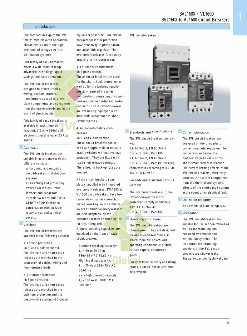
3VL circuit-breakers
Current Limitation
The 3VL circuit-breakers are
designed on the principles of
contact magnetic repulsion. The
contacts open before the
prospective peak value of the
short-circuit current is reached.
The current limiting effects of the
3VL circuit-breakers, effectively
protects the system components
from the thermal and dynamic
effects of the short-circuit current
in the event of an electrical fault.
Utilization category
All Siemens 3VL are category A.
Installation
The 3VL circuit-breakers are
suitable for use in open frames as
well as for mounting into
enclosed switchgear and
distribution systems. The
recommended mounting
positions of the 3VL circuit-
breakers are shown in the
illustrations under "technical data".

3VL160X ~ VL1600 断路器3VL160X to VL1600 Circuit-Breakers
1/4
VL160X
( A )In 16 20 25 32 40 50 63 80 100 125 160 200 250 315 400 500 630 800 1000 1250 1600
VL160
VL250
VL400
VL630
VL800
VL1250
VL1600
VL160
VL250
VL400
VL630
VL160
VL250
VL400
VL630
VL800
NSK-8872c
VL160X
VL160
VL250
VL400
VL630
VL800
VL1250
VL1600A
A
标准分断能力 N
额定电流/Rated current
用于线路保护
3 极断路器和�4 极断路器
用于电动机保护
3 极断路器
用于起动器组合
3 极断路器
隔离开关
3 极断路器和4 极断路器
高分断能力 H 极高分断能力 L
Standard switching capacity N High switching capacity H Very high switching capacity L
For line protection
3-pole circuit-breakersand4-pole circuit-breakers
3-pole circuit-breakersand4-pole circuit-breakers
For motor protection
3-pole circuit-breakers
3-pole circuit-breakers
For starter combinations
Non-automaticcircuit-breakers
Flexible
概览 Overview
160A 及以下 3VL 断路器的特点Features for 3VL Circuit-breakers up to 160A断路器 /Circuit-breaker VL160X VL160分断能力 (Icu,415V AC) 高达 /up to 70 kA 高达 /up to 100 kASwitching capacity (Icu,at 415V)模块化内部附件 /Modular internal accessories x x过电流脱扣器 /Overcurrent releases热 / 磁式 固定 / 固定 可调 /
可调 / 固定 可调thermal/magnetic fixed/fixed adjustable/
adjustable/fixed adjustable电子式 /electronic - x可互换式 /interchangeable - x尺寸 /Physical size高度 /height 157 175宽度 /width 105 105深度 /depth 81 81安装 /Mounting固定式 /fixed x x插入式 /plug-in x x抽屉式 /draw-out - x剩余电流装置 RCD/Residual current device RCD并排安装 /side mounting x -底部安装 /bottom mounting x x
x = 有此特点 x = available- = 无此特点 - = not available

1/5
3VL160X ~ VL1600 断路器3VL160X to VL1600 Circuit-Breakers 1
说明 Description
3VL160X~VL160 系列断路器带有工厂提供的输入和输出端子,适用于多股导线,铜排,以及带终端套管的细多股导线。另外,提供VL630 ~ VL1600 (630A~1600A)用的多种进线端子。
对于铜排或电缆的螺丝连接来说,可为 3VL160X~ VL1600 断路器提供合适的适配器。
3VL160X~VL1600 断路器可借助母排加长件连接。这些母排加长件是为连接标准化母排而设计和布置的,并可用于正面连接或背面连接。3VL1600 断路器提供有正面母排连接件。
该系列断路器可提供上进线、下进线,技术数据保持不变。带 RCD 模块的断路器可从顶部或底部进线。
与进线端连接的未绝缘导线必须在灭弧室上方飞弧距离范围内进行绝缘。为此,可使用相间隔板或端子盖。
对于所有的 3VL 160X~ VL1600 系列断路器来说,内部附件 (分励脱扣器,辅助开关和报警开关) 的连接件提供端子螺丝。
对于所有的 3VL 系列断路器来说,辅助脱扣器(分励脱扣器和欠压脱扣器)以及辅助开关和报警开关均可在现场容易地连接到各装置的端子上。
储能操作机构始终装有端子。装有辅助开关的旋转驱动操作机构始终提供有连接导线。
防护等级
断路器 IP20面框 IP40端子盖 IP30带正面旋转直接操作机构 IP40带加长旋转操作机构 IP65带电动机操作机构 IP30带电动机操作机构和门开孔面框 IP40插入式 / 抽屉式插座 IP20
结构
3VL160X 断路器
3VL160X 系列断路器的主要部件是三个带输入和输出端子的导电回路。静触头和动触头配置的方式能使触头的磁斥在短路条件下得到利用。该系列断路器结合灭弧室一起使用,生成一个动态阻抗,该动态阻抗通过减少 I2t和 IP 能量实现了限流性能。
脱扣器在工厂装配,并且在各极中设计有固定或可调的过载脱扣器和固定短路脱扣器。
断路器设有自由脱扣机构。
在断路器操作机构的右边和左边均设有双隔离辅助室,用于辅助脱扣器和辅助开关。
3VL160~VL630 断路器
导电回路布置、触头配置和断路器机构布置均与 3VL160X 系列断路器相 同 。 只 是 在 脱 扣 结 构 上 与3VL160X 不同。
● 采用热 /磁式和电子式设计的脱扣器均可现场安装,无需专用工具。
● 热/磁式脱扣器的过载脱扣器和短路脱扣器均可调整。
3VL800~VL1600 断路器
与 3VL160X~VL630 系列断路器的导电回路和操作机构的布置是相同的。不过, 3VL800~ VL1600 系列只有电子式脱扣器。
对于 3VL 系列断路器用的所有电子式脱扣器设计来说,电流互感器内置于一个独立的脱扣器中。它们将一个与负荷电流成正比的信号提供给电子式过电流脱扣器系统。
所有的 3VL 数字式电子脱扣器都测量实际 RMS 电流。以这种方式测量可确保当配电系统中有谐波时能够精确地测量电流值。
过电流脱扣器系统
1. 3VL160X~VL630 断路器的热/磁式过电流脱扣器。
过电流和短路保护脱扣器均是借助双金属或电磁线圈来实现的。这些脱扣器可提供有两种类型,即整定值固定型和整定值可调型。
线路保护用 4 极断路器具有两种过电流脱扣器,一种是可在所有 4 极中提供过电流保护,另一种是在第4 (N) 极中不带过电流保护。110A及以上,第 4 (N) 极中的脱扣器整定在 60% 的三相主电路电流 (Ir),以便保证导电截面减小的 N 极的安全。起动器组合用断路器通常与电动机型接触器和匹配的过载继电器组合使用。
隔离开关具有整定值固定的短路保护脱扣器,因而无需使用后备熔断器。这些装置不含有过载保护。4 极断路器在第 4 (N) 极中不设有短路保护。
2. 电动机保护用 3VL160~ VL630断路器的过电流脱扣器。
电子式脱扣器系统由下列部件组成:
● 3 个电流互感器● 带微处理器的电子测量装置● 脱扣电磁线圈
脱扣器系统无需使用辅助电源。
要使微处理器的脱扣器正常工作,所需的最小负荷电流约为断路器相应额定电流 In 的 20%。
在电子式过电流脱扣器模块的输出处设有一个脱扣电磁线圈。在发生过载或短路时,该脱扣电磁线圈使断路器脱扣。
3VL160X ~ VL1600 断路器3VL160X to VL1600 Circuit-Breakers
1/6
The 3VL160X to VL160 circuit-breaker families are factorysupplied with both incoming andoutgoing terminals suitable forstranded conductors, flexiblecopper bus, finely stranded wireconductors with end sleeves.Multiple feedin terminals forVL630 to VL1600 (sizes 630A to1600A) are available.
For the screw connection of solidand flexible copper busbars orcable, appropriate adapters areavailable for the 3VL160X toVL1600 circuit-breakers.
The 3VL160X to VL1600 circuit-breakers may be connected by busextenders. These are designedand laid out for the connection ofstandardized busbars andavailable for front or rearconnections. The 3VL1600 circuit-breaker is supplied with frontconnection busbar pieces.
The incoming and outgoing sidecan be selected on the circuit-breaker as desired. The electricaldata remains unchanged. Circuit-breakers with RCD modules arefed from top or bottom.
Uninsulated conductors which areconnected to the upper terminalsmust be insulated in thearcventing space for spacerequired above arc chutes.Interphase barriers or terminalcovers can be used for thispurpose.
For the 3VL160X to VL1600circuit-breaker families, theconnections for the integratedaccessories (auxiliary releases,auxiliary and alarm switches) areavailable with terminal screws.
For all circuit-breakers of the 3VLfamily, the auxiliary releasedevices (shunt release andundervoltage) and auxiliary andalarm switches are easily fieldwired directly to terminals oneach device.
The stored energy operatingmechanisms are always equippedwith terminals. The rotary drive
operators supplied with auxiliaryswitches are always suppliedwith connecting leads.
Degree of protection
Circuit-breaker IP 20Cover frame IP 40Terminal covers IP 30With front rotarydirect drive IP 40With rotarydrive extended IP 65With motor operator IP 30With motor operatorand cover framefor door cutout IP 40Plug-in socket/draw-out IP 20
Construction
3VL160X circuit-breakers
The main components of the3VL160X circuit-breaker familyare the three conducting pathswith incoming and out-goingterminals. The fixed andmoveable contacts are configuredin such a manner as to employmagnetic repulsion of thecontacts under short-circuitconditions. In conjunction withthe arc quenching chambers, adynamic impedance is generatedthat causes current limitation byreducing the damaging effects ofI2t and the Ip energy createdduring short-circuits. The releaseis factory fitted and is designedwith both fixed or adjustableoverload releases and fixed short-circuit releases in each pole. Thebreaker has a trip freemechanism. On the right and onthe left of the breaker operatingmecha-nism are the doubleisolation accessory compart-ments for the auxiliary releasesand switches.
3VL160 to VL630 circuit-breakers
The arrangement of the conduct-ing path, contact configurationand the breaker mechanism isidentical to the 3VL160X circuit-breaker family. This exception tothe 3VL160X is related to the tripconstruction.
● The releases are field installablewith no special tools for boththermal/magnetic and electronicdesigns.
● The thermal/magnetic releaseshave both adjustable overloadand short-circuit releases.
3VL800 to VL1600 circuit-breakers
As with the 3VL160X to VL630families of circuit-breakers, thearrangement of the conductingpaths and operating mechanismsis identical. The 3VL800 toVL1600 families, however, areavailable only in an electronicrelease design.
As with all of the electronicrelease designs for the 3VLcircuit-breaker families, thecurrent transformers are housedin a separable release. Theysupply a signal proportional to theload current to the electronicovercurrent release system.
All of the 3VL digital releasecircuit-breakers measure trueRMS current. This type ofmeasurement ensures the mostaccurate means of measuringcurrents in today's harmonic filledelectrical distributions systems.
Overcurrent release systems
1. Overcurrent releases of the3VL160X to VL630 circuit-breakers ther mal/magnetic
The overcurrent and short-circuitreleases function by means ofbimetals or solenoids. They canbe supplied either as fixed settingor adjustable.
The 4-pole circuit-breakers for lineprotection can be supplied withovercurrent releases in all 4 polesor without overcurrent releases inthe 4th (N) pole. From 110A andabove, the releases in the 4th (N)pole are set at 60% of current inthe 3 main conducting paths soas to ensure a safe protection ofneutral conductors with reducedcross-sections.
说明 Description
The circuit-breakers for startercombination applications areusually combined with motorcontactors and matched overloadrelays.
The non-automatic circuit-breakers are equipped with fixedshort-circuit release settings sothat back-up fuses are notrequired. These devices do notcontain overload protection. 4-pole circuit-breakers do not havea short-circuit release in the 4th
(N) pole.
2. Overcurrent releases of the3VL160 to VL630 circuit-breakers for motor protection
The electronic overcurrentrelease system consists of:
● 3 current transformers● evaluation electronics with
microprocessor● tripping solenoid.
An auxiliary power supply is notneeded for the release system.
Activation of the microprocessorbased release requires aminimum load current ofapproximately 20% of therespective rated current In of thecircuit-breaker.
At the output of the electronicovercurrent release module, thereis a tripping solenoid, which tripsthe circuit-breaker in the event ofoverload or short-circuit.

1/7
3VL160X ~ VL1600 断路器3VL160X to VL1600 Circuit-Breakers 1
过电流脱扣器系统—概览 Overcurrent release system - Overview
缩写(功能)
L = LTD = 过载保护S = STD = 短路保护 (短延时)I = INST = 短路保护(瞬时)G = GF = 接地故障保护
应用
Line = 线路保护Mot = 电动机保护Gen = 发电机保护Start = 起动器组合
I = INST = Short-circuit pro-tection (instantaneous)
G = GF = Earth fault protection
ApplicationLine = Line protectionMot = Motor protectionGen = Generator protectionStart = Starter combinationsIsol = Non-automatic
circuit-breaker withself protection
adj. = adjustableETU = Electronic overcurrent
releasesLCDETU = Electronic overcurrent
releases with LCD
壳架等级 热 / 磁式过电流脱扣器 电子式过电流脱扣器
Size Thermal/Magnetic overcurrent releases Electronic overcurrent releases
固定 / 固定 可调 / 固定 -/ 固定 -/ 可调 可调 / 可调 ETU LCD ETU
fixed/fixed adj./fixed -/fixed -/adj. adj./adj.
VL160X Line Line Isol - - - -
VL160 - - Isol Start Line Line Mot Gen Line Mot Gen
VL250 - - Isol Start Line Line Mot Gen Line Mot Gen
VL400 - - Isol Start Line Line Mot Gen Line Mot Gen
VL630 - - Isol Start Line Line Mot Gen Line Mot Gen
VL800 - - Isol - - - Line - - Line -
VL1250 - - Isol Start - - Line - - Line -
VL1600 - - Isol Start - - Line - - Line -
接地故障保护
说明
接地故障脱扣器“G”检测流经大地
并可能在系统中引起火灾的故障电
流。几个串联断路器可借助可调的
动作时间实现选择性保护。
下列测量方法可用于检测 N 导线和
接地故障电流:
矢量和
在对称负载的系统中进行接地故障
检测
三相电流按照矢量和予以计算。
N 导线电流是直接测量的,并且实
现对 N 导线过载保护。
过电流脱扣器借助三相电流和 N
导线电流的矢量和来计算接地故障
电流。
3 极断路器,在 N 导线电流中的电流
互感器
对于 4 极断路器来说,N 导线用的
第 4 个电流互感器在内部安装。
通过位于变压器接地中性点处
的电流互感器对接地故障电流
进行直接检测
电流互感器直接安装在变压器的接
地中性点处。
3 极断路器,位于变压器接地中性点处
的电流互感器
剩余电流检测 (RCD) 见第 1/52 页。
外部电流互感器见第 1/18 页。
Earth fault protection
Description
The earthfault release "G" detects
fault currents which flow through
earth and could cause fires in the
system. Several circuit-breakers
connected in series can be given
time-graded discrimination by
means of the adjustable operating
delay time.
The following measuring
methods can be used to detect
N-conductor and earth fault
currents:
Vectorial summation
Earth fault detection in symmetri-
cally loaded systems
The three phase currents are
evaluated following vectorial
summation
The N-conductor current is
measured directly and is
evaluated for N-conductor
overload protection.
The overcurrent release calcu-
lates the earthfault current by
means of vectorial summation of
the three phase currents and the
N-conductor current.
3-pole circuit-breaker, currenttransformer in the N-conductor
current
In the case of 4-pole circuit-
breakers, the 4th current
transformer for the N-conductor
is installed internally.
Direct detection of the earth-
fault current via a current
transformer at the earthed
star point of the transformer
The current transformer is installed
directly at the earthed star point of
the transformer.
3-pole circuit-breaker, currenttransformer at the earthed star point
of the transformer
Residual current detection (RCD)
see page 1/52.
External current transformer see
page 1/18.
NSK - 10 22
L1
L2
L3
PE
3VL
NSK - 10 23
L1
L2
L3
N
PE
3VL
L1L2
L33VL
T6
NSK-1021
PE
N
Isol = 隔离开关adj. = 可调整ETU = 电子式过电流脱扣器LCDETU = 带 LCD 的电子式过
电流脱扣器
Abbrevations (Functions)
L = LTD = Overload protectionS = STD = Short-circuit pro-
tection (short time delay)
NSK - 10 20
L1
L2
L3
N
PE
3VL
T5
3VL160X ~ VL1600 断路器3VL160X to VL1600 Circuit-Breakers
1/8
NSK-1024
L
I
NSK-1025
L
I
NSK-1026
L
I
2 4 6
63AOFF
CAT.A50∞ CTM ~=
NSK-1055
I1.0 .8
RInx
63AOFF
CAT.A50∞ CTM ~=
2 4 6
NSK-1056
I
nxI
10
9
7 8
6
5
iI
nI.8
x
.9
1.0
RI
n
I iIR50∞ C
=160A
CAT.ATM ~=
16 DCNSK-1057
NSK-1026
L
I
CAT.A =250A ~I n 25 AB
nxI
RIAlarm
X3
>1.05
25 AB
.45
.6
.9
1.0.95
.7.8
.4
.63
30
14
Rt 20.5
(S)RT
25
RI iI
17
8
I i
nxI
6
2.54
108
2
1.251.5
43
1011
56
Active
NSK-1058
过电流脱扣器系统—概览 Overcurrent release system - Overview
热磁式过电流脱扣器 TM
电子式过电流脱扣器 ETU用于 VL160~VL1600 壳架等级
应用:线路保护 - TM,功能 LI带固定的过载保护整定值,带固定的短路保护整定值,VL160X 壳架等级的具体选型,见选型表。
应用:线路保护 - TM,功能 LI带可调的过载保护整定值 IR = 0.8~1 x In,带固定的短路保护整定值,VL160X 壳架等级的具体选型,见选型表。
应用:线路保护 - TM,功能 LI带可调的过载保护整定值 IR = 0.8~1 x In,带可调的短路保护整定值 Ii = 5~10 x In,用于 VL160~VL630 壳架等级。
概述:脱扣器系统无需使用辅助电压。绿色闪烁 LED 表明微处理器运行正确。
应用:线路保护 - ETU10,功能 LI过载保护 IR = 0.4; 0.45; 0.5~0.95; 1 x In,时滞等级 TR = 2.5~30短路保护(瞬时) Ii = 1.25~11 x In
应用:线路和发电机保护 - ETU20,功能 LSI过载保护 IR = 0.4; 0.45; 0.5~0.95; 1 x In,短路保护 (短延时) Isd = 1.5~10 x IR,tsd = 0~0.5 秒,I2t 可选择有 / 无短路保护(瞬时) Ii = 11 x In (固定)
应用:线路保护 - ETU12,功能 LIG过载保护 IR = 0.4; 0.45; 0.5~0.95; 1 x In,时滞等级 TR = 2.5~30短路保护 (瞬时) Ii = 1.25~11 x In
接地故障保护:第一种测量方法:( GR) 三线系统 / 及 N 导线 (4 线系统) 中的电流矢量和 I∆n = In,第二种测量方法:(GGND) 通过安装在接地中性点处的电流互感器来直接检测接地故障电流,Ig = In (瞬时)
过载状态 (I > 1.05 x IR) 由常亮黄色 LED 显示,集成自测试功能测试装置用插入端口
NSK-1028
L
IG
NSK-1188
L
S
I
Alarm
>1.05
CAT.A
25 AEX3
.45
=250A
.6
1.0IR
.95
.9
.4
nI
nIx.7 .63
.8
108
Isd
sdt 7.5
~
sdRII 56
.2
(S)
t22
tsd
I1.5
ONxI
2.5
4 3 R
0OFF
t2I.1
.2
.4
Active
.3
.3.4
.5.1
25 AE
NSK-1059
.95
I
CAT.A
X3
>1.05
25 AD
R
xIn
.8
.9
Alarm (S)T1.0 2.530.4
.5
.45
.7 .63
R
iIRI
Rt
101417
25
2086
4
iI 1.2511
Active5
x In
6
8
10
4
2
3
1.5
=250AnI ~ 25 ADn nI = I
NSK-1060
1/9
3VL160X ~ VL1600 断路器3VL160X to VL1600 Circuit-Breakers 1
NSK-1024
L
I
NSK-1025
L
I
NSK-1026
L
I
2 4 6
63AOFF
CAT.A50∞ CTM ~=
NSK-1055
I1.0 .8
RInx
63AOFF
CAT.A50∞ CTM ~=
2 4 6
NSK-1056
I
nxI
10
9
7 8
6
5
iI
nI.8
x
.9
1.0
RI
n
I iIR50∞ C
=160A
CAT.ATM ~=
16 DCNSK-1057
NSK-1026
L
I
CAT.A =250A ~I n 25 AB
nxI
RIAlarm
X3
>1.05
25 AB
.45
.6
.9
1.0.95
.7.8
.4
.63
30
14
Rt 20.5
(S)RT
25
RI iI
17
8
I i
nxI
6
2.54
108
2
1.251.5
43
1011
56
Active
NSK-1058
过电流脱扣器系统—概览 Overcurrent release system - Overview
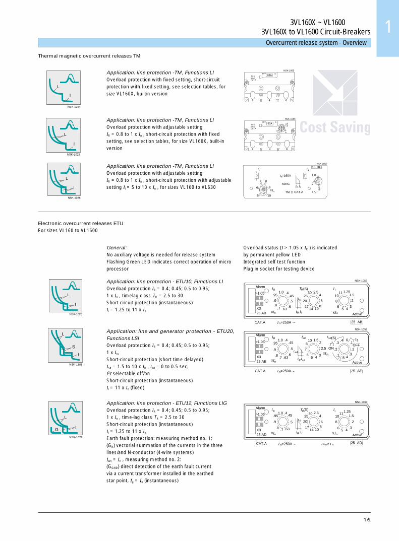
Thermal magnetic overcurrent releases TM
Electronic overcurrent releases ETUFor sizes VL160 to VL1600
Application: line protection -TM, Functions LIOverload protection with fixed setting, short-circuitprotection with fixed setting, see selection tables, forsize VL160X, builtin version
Application: line protection -TM, Functions LIOverload protection with adjustable settingIR = 0.8 to 1 x In , short-circuit protection with fixedsetting, see selection tables, for size VL160X, built-inversion
Application: line protection -TM, Functions LIOverload protection with adjustable settingIR = 0.8 to 1 x In , short-circuit protection with adjustablesetting Ii = 5 to 10 x In , for sizes VL160 to VL630
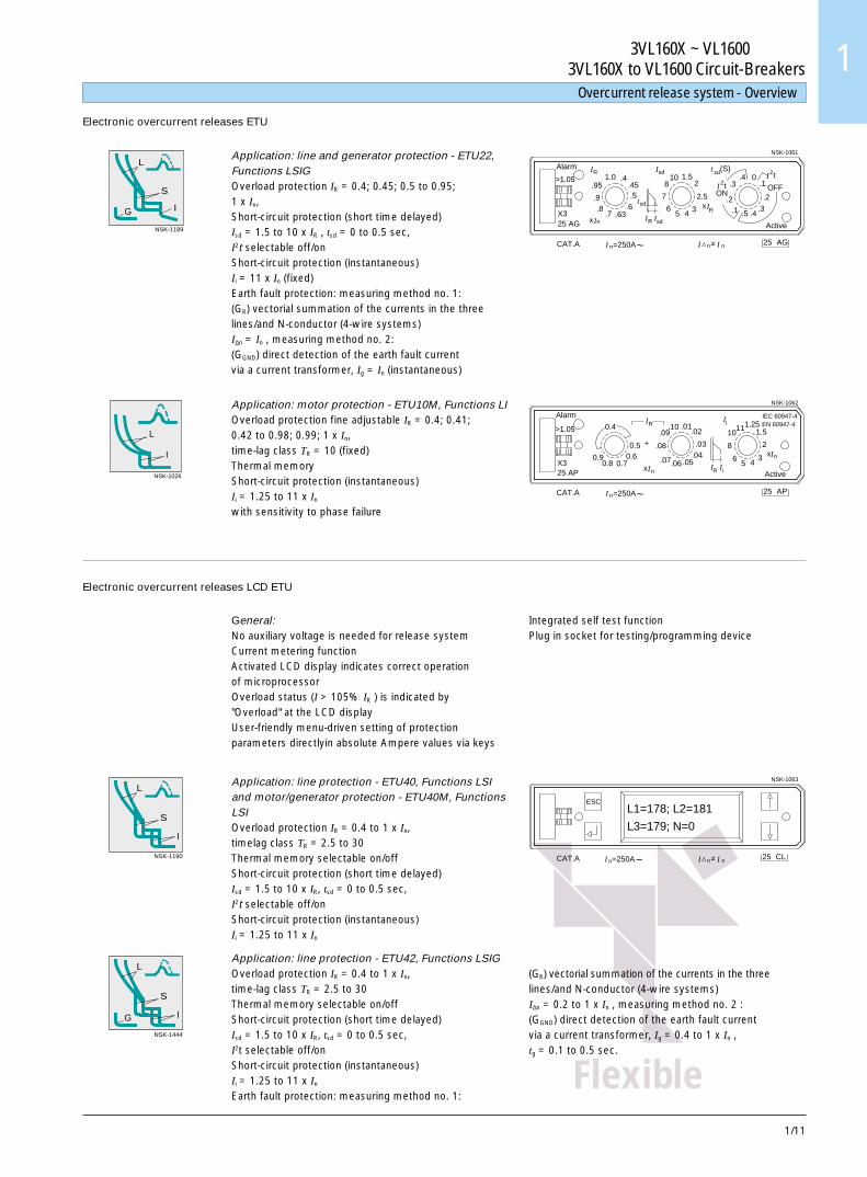
General:No auxiliary voltage is needed for release systemFlashing Green LED indicates correct operation of microprocessor
Application: line protection - ETU10, Functions LIOverload protection IR = 0.4; 0.45; 0.5 to 0.95;1 x In , timelag class TR = 2.5 to 30Short-circuit protection (instantaneous)Ii = 1.25 to 11 x In
Application: line and generator protection - ETU20,Functions LSIOverload protection IR = 0.4; 0.45; 0.5 to 0.95;1 x In,Short-circuit protection (short time delayed)Isd = 1.5 to 10 x IR , tsd = 0 to 0.5 sec,I2t selectable off/onShort-circuit protection (instantaneous)Ii = 11 x In (fixed)
Application: line protection - ETU12, Functions LIGOverload protection IR = 0.4; 0.45; 0.5 to 0.95;1 x In , time-lag class TR = 2.5 to 30Short-circuit protection (instantaneous)Ii = 1.25 to 11 x In
Earth fault protection: measuring method no. 1:(GR) vectorial summation of the currents in the threelines/and N-conductor (4-wire systems)I∆n = In , measuring method no. 2:(GGND) direct detection of the earth fault currentvia a current transformer installed in the earthedstar point, Ig = In (instantaneous)
Overload status (I > 1.05 x IR ) is indicatedby permanent yellow LEDIntegrated self test functionPlug in socket for testing device
NSK-1028
L
IG
NSK-1188
L
S
I
Alarm
>1.05
CAT.A
25 AEX3
.45
=250A
.6
1.0IR
.95
.9
.4
nI
nIx.7 .63
.8
108
Isd
sdt 7.5
~
sdRII 56
.2
(S)
t22
tsd
I1.5
ONxI
2.5
4 3 R
0OFF
t2I.1
.2
.4
Active
.3
.3.4
.5.1
25 AE
NSK-1059
.95
I
CAT.A
X3
>1.05
25 AD
R
xIn
.8
.9
Alarm (S)T1.0 2.530.4
.5
.45
.7 .63
R
iIRI
Rt
101417
25
2086
4
iI 1.2511
Active5
x In
6
8
10
4
2
3
1.5
=250AnI ~ 25 ADn nI = I
NSK-1060

3VL160X ~ VL1600 断路器3VL160X to VL1600 Circuit-Breakers
1/10
Flexible
过电流脱扣器系统—概览 Overcurrent release system - Overview
NSK-1189
L
S
IG
NSK-1026
L
I
sd
.95
25 AG
CAT.A
X3
.9
Ix n
.8
Alarm
>1.05RI sd
.5
.63.7.6 sdt
RI Isd
.45.41.0
I
4
7
65
Ix2.5
R3
1.58
10t
2 OFF
Active
I t
.5
ON.2
.1
.2
.4.3
.4(S)
2 .3 .10 I2t
=250AnI ~ 25 AGn
NSK-1061
nI = I
Alarm
25 AP
CAT.A
>1.05
X3
I.100.4
0.70.80.9
+
xI
0.60.5
R
n
.07.06
.08
.09
IEC 60947-4EN 60947-4iI
11.01 1.2510
.04.05
.03
.02
6
RI iI
8
3
1.5
5 4
Active
Inx2
=250AnI ~ 25 AP
NSK-1062
电子式过电流脱扣器 ETU
应用:线路和发电机保护 - ETU22,功能 LSIG过载保护 Ir = 0.4; 0.45; 0.5~0.95; 1 x In,短路保护 (短延时) Isd = 1.5~10 x IR,tsd = 0~0.5 秒,I2t 可选择有 / 无短路保护 (瞬时) Ii = 11 x In (固定)接地故障保护:第一种测量方法:(GR) 三线系统 /及N 导线(4 线系统) 中的电流矢量和 I∆n = In,第二种测量方法: (GGND)通过电流互感器来直接检测接地故障电流,Ig = In (瞬时)
应用:电动机保护 - ETU10M,功能 LI过载保护可微调 IR =0.41; 0.42~0.98; 0.99; 1 x In,时滞等级 TR = 10 (固定)热记忆短路保护(瞬时) Ii = 1.25~11 x In
具有断相保护功能
电子式过电流脱扣器 LCD ETU
NSK-1444
L
S
IG
NSK-1190
L
S
I
概述:脱扣器系统无需使用辅助电压电流计量功能激活的 LCD 显示器表明微处理器运行正确过载状态(I > 105% IR) 由 LCD 显示器显示“过载”通过各键直接采用安培绝对值以用户友好的菜单驱动方式整定保护参数
应用:线路保护 - ETU40,功能 LSI 和电动机 /发电机保护- ETU40M,功能 LSI过载保护 IR = 0.4~1 x In,时滞等级 TR = 2.5~30热记忆可选择有 / 无短路保护 (短延时) Isd = 1.5~10 x IR,tsd = 0~0.5秒,I2t 可选择有 / 无短路保护 (瞬时) Ii = 1.25~11 x In
应用:线路保护 - ETU42,功能 LSIG过载保护 IR = 0.4~1 x In,时滞等级 TR = 2.5~30热记忆可选择有 / 无短路保护 (短延时) Isd = 1.5~10 x IR,tsd = 0~0.5秒,I2t 可选择有 / 无短路保护 (瞬时) Ii = 1.25~11 x In
接地故障保护:第一种测量方法:(GR) 三线系统 /及N 导线(4 线系统) 中的电流矢量和 I∆n = 0.2~1 x In,第二种测量方法:(GGND) 通过电流互感器来直接检测接地故障电流,Ig = 0.4~1 x In,tg = 0.1~0.5 秒
集成自测试功能测试 / 编程装置用插入端口
ESCL1=178; L2=181
L3=179; N=0
CAT.A =250AnI ~ 25 CLn nI = I
NSK-1063
1/11
3VL160X ~ VL1600 断路器3VL160X to VL1600 Circuit-Breakers 1
Flexible
过电流脱扣器系统—概览 Overcurrent release system - Overview
NSK-1189
L
S
IG
NSK-1026
L
I
sd
.95
25 AG
CAT.A
X3
.9
Ix n
.8
Alarm
>1.05RI sd
.5
.63.7.6 sdt
RI Isd
.45.41.0
I
4
7
65
Ix2.5
R3
1.58
10t
2 OFF
Active
I t
.5
ON.2
.1
.2
.4.3
.4(S)
2 .3 .10 I2t
=250AnI ~ 25 AGn
NSK-1061
nI = I
Alarm
25 AP
CAT.A
>1.05
X3
I.100.4
0.70.80.9
+
xI
0.60.5
R
n
.07.06
.08
.09
IEC 60947-4EN 60947-4iI
11.01 1.2510
.04.05
.03
.02
6
RI iI
8
3
1.5
5 4
Active
Inx2
=250AnI ~ 25 AP
NSK-1062
Electronic overcurrent releases ETU
Application: line and generator protection - ETU22,Functions LSIGOverload protection IR = 0.4; 0.45; 0.5 to 0.95;1 x In,Short-circuit protection (short time delayed)Isd = 1.5 to 10 x IR , tsd = 0 to 0.5 sec,I2t selectable off/onShort-circuit protection (instantaneous)Ii = 11 x In (fixed)Earth fault protection: measuring method no. 1:(GR) vectorial summation of the currents in the threelines/and N-conductor (4-wire systems)I∆n = In , measuring method no. 2:(GGND) direct detection of the earth fault currentvia a current transformer, Ig = In (instantaneous)
Application: motor protection - ETU10M, Functions LIOverload protection fine adjustable IR = 0.4; 0.41;0.42 to 0.98; 0.99; 1 x In,time-lag class TR = 10 (fixed)Thermal memoryShort-circuit protection (instantaneous)Ii = 1.25 to 11 x In
with sensitivity to phase failure
Electronic overcurrent releases LCD ETU
NSK-1444
L
S
IG
NSK-1190
L
S
I
General:No auxiliary voltage is needed for release systemCurrent metering functionActivated LCD display indicates correct operationof microprocessorOverload status (I > 105% IR ) is indicated by"Overload" at the LCD displayUser-friendly menu-driven setting of protectionparameters directlyin absolute Ampere values via keys
Application: line protection - ETU40, Functions LSIand motor/generator protection - ETU40M, FunctionsLSIOverload protection IR = 0.4 to 1 x In,timelag class TR = 2.5 to 30Thermal memory selectable on/offShort-circuit protection (short time delayed)Isd = 1.5 to 10 x IR, tsd = 0 to 0.5 sec,I2t selectable off/onShort-circuit protection (instantaneous)Ii = 1.25 to 11 x In
Application: line protection - ETU42, Functions LSIGOverload protection IR = 0.4 to 1 x In,time-lag class TR = 2.5 to 30Thermal memory selectable on/offShort-circuit protection (short time delayed)Isd = 1.5 to 10 x IR, tsd = 0 to 0.5 sec,I2t selectable off/onShort-circuit protection (instantaneous)Ii = 1.25 to 11 x In
Earth fault protection: measuring method no. 1:
Integrated self test functionPlug in socket for testing/programming device
ESCL1=178; L2=181
L3=179; N=0
CAT.A =250AnI ~ 25 CLn nI = I
NSK-1063
(GR) vectorial summation of the currents in the threelines/and N-conductor (4-wire systems)I∆n = 0.2 to 1 x In , measuring method no. 2 :(GGND) direct detection of the earth fault currentvia a current transformer, Ig = 0.4 to 1 x In ,tg = 0.1 to 0.5 sec.

3VL160X ~ VL1600 断路器3VL160X to VL1600 Circuit-Breakers
1/12
说明 Description
3VL 断路器可根据要求与整机一起提供内部附件 (例如辅助报警开关,欠压脱扣器或分励脱扣器)。所供类型,可参见订货号后缀表。另外,单独提供外部附件 (旋转驱动机构,电动机构,抽出式或插入式部件以及各种接线端子)。
固定安装式,插入式或抽出式
固定安装式断路器为基本类型。它们通过选配适当的部件可容易地改装成插入式或抽出式断路器。该配件含有插入式断路器用的刀形触头、联锁销和端子盖。抽出式配件还含有托架。通过增设面框和摇手柄,可进行闭门抽出。
操作机构
3VL 系列断路器在其基本类型中都含有扳动手柄操作机构。该操作机构也可用作开关位置指示器,其不仅显示合闸 (ON) 和分闸 (OFF),还显示自由脱扣 (TRIPPED) 位置。
如果内部脱扣机构是通过过电流例如过载或短路等而动作,则扳动手柄处于自由脱扣 (TRIPPED) 位置。由欠压脱扣器或分励脱扣器引起的动作,也将使扳动手柄处于自由脱扣 (TRIPPED) 位置。在断路器可进行重合闸之前,扳动手柄必须移到分闸 / 复位 (OFF/RESET) 位置。这就可实现内部脱扣器机构的复位,以及实现断路器主触头的重合闸 (见右图)。
扳动手柄加长件将随 3VL1250 和VL1600 断路器一起提供。对于3VL400~ VL800 断路器来说,如有需要,该装置将单独订货。
正面旋转直接驱动机构
这些机构直接安装于断路器的正面,并且将扳动手柄动作从直线运动形式变成旋转形式。
AN
S1-
5174
a
分闸复位
合闸
自由脱扣
NS
K -
1064
对于带超前动作辅助触头的断路器来说,可提前提供欠压脱扣器电源,这将使断路器可以闭合。
加长旋转驱动机构(整套机构)
如果断路器安装在开关柜和配电板内,则加长旋转驱动机构可用于柜门和移动式盖的装置中。这些机构是整套提供的,包括铰接轴机构。
开关的操作及复位(RESET),对扳动机构适用的也同样适用于旋转驱动机构。操作手柄(旋钮)的位置显示断路器所处的状态。
所有旋转驱动机构都可借助合适的挂锁锁定在分闸 (OFF) 位置。因此,所有装有这些驱动机构和相应端子盖的
3VL 系列断路器都可用作主开关。
主端子,基本供货范围和选项
3VL160X 和 VL160 断路器 3VL250~VL1250 断路器 3VL1600 断路器
铜电缆和铜排卡箍式端子 电缆接线头或母排用螺母定位板 铜排加长式端子
主功率输入和输出终端
断路器 端子,基本供货范围 连接件概览
压板式端子 公制螺纹螺母定位板 铝端子 背后端子 正面母排端子VL160X 压板式端子 x x x x xVL160 x x x x xVL250 公制螺纹螺母定位板 x x x x xVL400 x x x x xVL630 - x x x xVL800 - x x x xVL1250 - x x x xVL1600 加长铜排 - - - x x
x = 可用- = 不可用
NSK-1080
NS
K-1
082
NS
K-1
075
扳动手柄机构位置
具有挂锁锁定的旋转驱动机构
1/13
3VL160X ~ VL1600 断路器3VL160X to VL1600 Circuit-Breakers 1
说明 Description
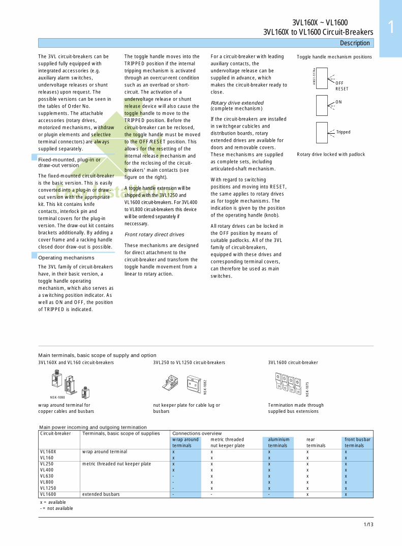
The 3VL circuit-breakers can besupplied fully equipped withintegrated accessories (e.g.auxiliary alarm switches,undervoltage releases or shuntreleases) upon request. Thepossible versions can be seen inthe tables of Order No.supplements. The attachableaccessories (rotary drives,motorized mechanisms, withdrawor plugin elements and selectiveterminal connectors) are alwayssupplied separately.
Fixed-mounted, plug-in ordraw-out version
The fixed-mounted circuit-breakeris the basic version. This is easilyconverted into a plug-in or draw-out version with the appropriatekit. This kit contains knifecontacts, interlock pin andterminal covers for the plug-inversion. The draw-out kit containsbrackets additionally. By adding acover frame and a racking handleclosed door draw-out is possible.
Operating mechanisms
The 3VL family of circuit-breakershave, in their basic version, atoggle handle operatingmechanism, which also serves asa switching position indicator. Aswell as ON and OFF, the positionof TRIPPED is indicated.
The toggle handle moves into theTRIPPED position if the internaltripping mechanism is activatedthrough an overcur-rent conditionsuch as an overload or short-circuit. The activation of aundervoltage release or shuntrelease device will also cause thetoggle handle to move to theTRIPPED position. Before thecircuit-breaker can be reclosed,the toggle handle must be movedto the OFF/RESET position. Thisallows for the resetting of theinternal release mechanism andfor the reclosing of the circuit-breakers' main contacts (seefigure on the right).
A toggle handle extension will beshipped with the 3VL1250 andVL1600 circuit-breakers. For 3VL400to VL800 circuit-breakers this devicewill be ordered separately ifneccessary.
Front rotary direct drives
These mechanisms are designedfor direct attachment to thecircuit-breaker and transform thetoggle handle movement from alinear to rotary action.
For a circuit-breaker with leadingauxiliary contacts, theundervoltage release can besupplied in advance, whichmakes the circuit-breaker ready toclose.
Rotary drive extended(complete mechanism)
If the circuit-breakers are installedin switchgear cubicles anddistribution boards, rotaryextended drives are available fordoors and removable covers.These mechanisms are suppliedas complete sets, includingarticulated-shaft mechanism.
With regard to switchingpositions and moving into RESET,the same applies to rotary drivesas for toggle mechanisms. Theindication is given by the positionof the operating handle (knob).
All rotary drives can be locked inthe OFF position by means ofsuitable padlocks. All of the 3VLfamily of circuit-breakers,equipped with these drives andcorresponding terminal covers,can therefore be used as main
switches.
AN
S1-
5174
a
OFFRESET
ON
Tripped
Main terminals, basic scope of supply and option3VL160X and VL160 circuit-breakers 3VL250 to VL1250 circuit-breakers 3VL1600 circuit-breaker
wrap around terminal for nut keeper plate for cable lug or Termination made throughcopper cables and busbars busbars supplied bus extensions
Main power incoming and outgoing terminationCircuit-breaker Terminals, basic scope of supplies Connections overview
wrap around metric threaded aluminium rear front busbarterminals nut keeper plate terminals terminals terminals
VL160X wrap around terminal x x x x xVL160 x x x x xVL250 metric threaded nut keeper plate x x x x xVL400 x x x x xVL630 - x x x xVL800 - x x x xVL1250 - x x x xVL1600 extended busbars - - - x x
x = available- = not available
NSK-1080
NS
K-1
082
NS
K-1
075
Toggle handle mechanism positions
Rotary drive locked with padlock

3VL160X ~ VL1600 断路器3VL160X to VL1600 Circuit-Breakers
1/14
储能操作机构
3VL160X~VL1600 断路器 (壳架等级 160~1600A) 可安装电动机操作机构,用于远程操作合闸和分闸。
这些用于 3VL160X~ VL800 断路器的储能操作机构均具有储能特点 (用于同步),最大合闸速度 tE ≤ 100ms。3VL1250 和 VL1600 断路器将由电动机操作 (tE ≤ 5s)。它们也可实现断路器的远距离分闸。储能操作机构始终提供有挂锁锁定装置。可选的柱形锁定装置可提供用于所有的储能操作机构。
这些装置可用于操作机构的电气闭锁和机械闭锁。所有远程操作机构都装有手动执行机构,以便进行维护。
说明 Description
Flexible
1 & 2
NSK-1033b
1 HS
2 HS
U<
U<
U<
U<
U<
3 HS
4 HS
1 AS
2 AS
U<
U<
U<
U<
1 HS + 1 AS
2 HS + 1 AS
U<
1 HS + 1 AS
2 HS + 1 AS
2 HS + 2 AS
1 HS
2 HS
3 HS
4 HS
1 AS
2 AS
1 & 2
1 & 2
2
1 & 2
2
1 & 2
1 & 2
2
1 HS
2 HS
3 HS
4 HS
A
3 极断路器
4 极断路器
N 极
组左
左 右
左表
右
带辅助开关和报警开关的 3VL 断路器的位置配置
辅助脱扣器和辅助开关
分励脱扣器 / 欠压脱扣器
HS 一个辅助开关 1 个常开 (NO) 触头或 1 个常闭(NC) 触头
AS 一个报警开关 1 个常开 (NO) 触头或 1 个常闭(NC) 触头
第 1 组 - VL160X, VL160, VL250, VL400第 2 组 - VL630, VL800, VL1250, VL1600
报警开关或报警开关组合将不适合装入第 2 组断路器的右极。
欠压脱扣器,超前动作辅助开关
只有在欠压脱扣器已通电之后,断路器才能合闸。 如果脱扣器未通电,断路器虽有闭合操作,但不能实现真正闭合。
应避免欠压脱扣器没有通电而频繁地使断路器空合闸,因为这样会缩短断路器的寿命。
所有欠压脱扣器的设计和测试都符合所有在 IEC 60 947 标准中所列的适用要求 (释放电压 0.70~0.35Ue 断路器可在 -0.85~1.10Ue 之间接通)。
对于带超前动作辅助开关触头的断路器来说,欠压脱扣器可提前得电,这使断路器合闸准备就绪。
对于 3VL 系列断路器来说,超前动作辅助开关可随旋转机构一起供货。有关详情,请见附件选型和订购表。
分励脱扣器
分励脱扣器用于断路器的远程脱扣。
分励脱扣器的线圈是为短时操作而设计的。其内部具有线圈电流自动切断开关。
这些装置是符合 IEC 60 947 标准(脱扣电压 0.70~1.10Ue)。
分励脱扣器不能连续施加断开信号来达到防止断路器合闸。
辅助开关
辅助开关 (HS) 用于信号发送和控制。辅助开关的各种功能见上图。
报警开关
报警开关 (AS) 只有在过电流条件,例如过载或短路引起断路器脱扣时才动作,但是当分励脱扣器或欠压脱扣器引起断路器脱扣时,报警开关也会被激活。
辅助报警开关的安装(见上图)
断路器安装辅助开关和报警开关,取决于断路器内部附件的安装位置以及断路器的壳架等级。不同壳架的断路器其安装位置各不相同。
1/15
3VL160X ~ VL1600 断路器3VL160X to VL1600 Circuit-Breakers 1
Flexible
1 & 2
NSK-1033b
1 HS
2 HS
U<
U<
U<
U<
U<
3 HS
4 HS
1 AS
2 AS
U<
U<
U<
U<
1 HS + 1 AS
2 HS + 1 AS
U<
1 HS + 1 AS
2 HS + 1 AS
2 HS + 2 AS
1 HS
2 HS
3 HS
4 HS
1 AS
2 AS
1 & 2
1 & 2
2
1 & 2
2
1 & 2
1 & 2
2
1 HS
2 HS
3 HS
4 HS
3-polecircuit-breakers
4-polecircuit-breakers
left leftright right
N - pole
A
Use table on the left
Group
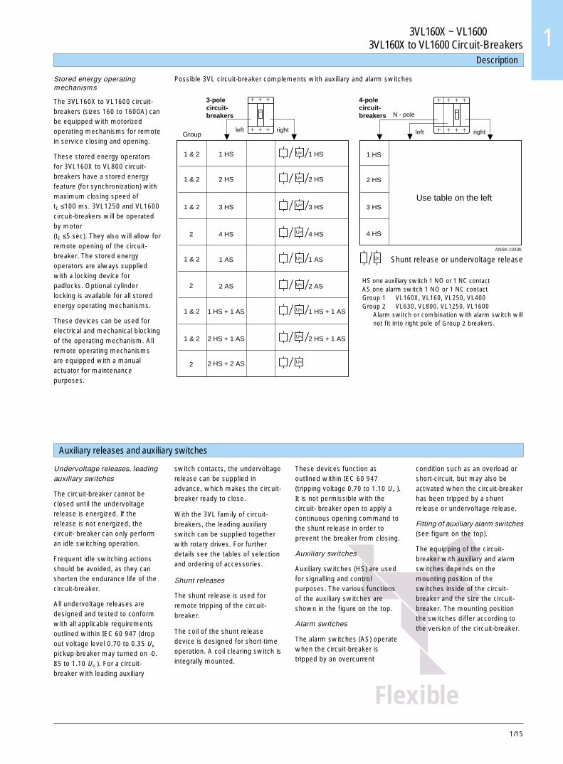
Possible 3VL circuit-breaker complements with auxiliary and alarm switches
说明 Description
Auxiliary releases and auxiliary switches
Shunt release or undervoltage release
HS one auxiliary switch 1 NO or 1 NC contactAS one alarm switch 1 NO or 1 NC contactGroup 1 � VL160X, VL160, VL250, VL400Group 2 � VL630, VL800, VL1250, VL1600
Alarm switch or combination with alarm switch willnot fit into right pole of Group 2 breakers.
Undervoltage releases, leadingauxiliary switches
The circuit-breaker cannot beclosed until the undervoltagerelease is energized. If therelease is not energized, thecircuit- breaker can only performan idle switching operation.
Frequent idle switching actionsshould be avoided, as they canshorten the endurance life of thecircuit-breaker.
All undervoltage releases aredesigned and tested to conformwith all applicable requirementsoutlined within IEC 60 947 (dropout voltage level 0.70 to 0.35 Ue
pickup-breaker may turned on -0.85 to 1.10 Ue ). For a circuit-breaker with leading auxiliary
switch contacts, the undervoltagerelease can be supplied inadvance, which makes the circuit-breaker ready to close.
With the 3VL family of circuit-breakers, the leading auxiliaryswitch can be supplied togetherwith rotary drives. For furtherdetails see the tables of selectionand ordering of accessories.
Shunt releases
The shunt release is used forremote tripping of the circuit-breaker.
The coil of the shunt releasedevice is designed for short-timeoperation. A coil clearing switch isintegrally mounted.
These devices function asoutlined within IEC 60 947(tripping voltage 0.70 to 1.10 Ue ).It is not permissible with thecircuit- breaker open to apply acontinuous opening command tothe shunt release in order toprevent the breaker from closing.
Auxiliary switches
Auxiliary switches (HS) are usedfor signalling and controlpurposes. The various functionsof the auxiliary switches areshown in the figure on the top.
Alarm switches
The alarm switches (AS) operatewhen the circuit-breaker istripped by an overcurrent
Stored energy operatingmechanisms
The 3VL160X to VL1600 circuit-breakers (sizes 160 to 1600A) canbe equipped with motorizedoperating mechanisms for remotein service closing and opening.
These stored energy operatorsfor 3VL160X to VL800 circuit-breakers have a stored energyfeature (for synchronization) withmaximum closing speed oftE ≤100 ms. 3VL1250 and VL1600circuit-breakers will be operatedby motor(tE ≤5 sec). They also will allow forremote opening of the circuit-breaker. The stored energyoperators are always suppliedwith a locking device forpadlocks. Optional cylinderlocking is available for all storedenergy operating mechanisms.
These devices can be used forelectrical and mechanical blockingof the operating mechanism. Allremote operating mechanismsare equipped with a manualactuator for maintenancepurposes.
condition such as an overload orshort-circuit, but may also beactivated when the circuit-breakerhas been tripped by a shuntrelease or undervoltage release.
Fitting of auxiliary alarm switches(see figure on the top).
The equipping of the circuit-breaker with auxiliary and alarmswitches depends on themounting position of theswitches inside of the circuit-breaker and the size the circuit-breaker. The mounting positionthe switches differ according tothe version of the circuit-breaker.
1/16
额定电流RatedcurrentIn
A
过载反时限脱扣器“L”的整定电流Settingcurrent ofinverse-timedelayedoverloadrelease "L"IR
A
短路瞬时脱扣器“I”的整定电流Operatingcurrent ofcurrent ofinstantaneousshort-circuitrelease "I"Ii
A
标准分断能力N40/45/50kA,在 380/415V AC 时见第 1/60 页Standard switching capacity N40/45/50 kA at 380/415 V ACsee page 1/60.订货号根据第 1/30 页和第 1/31 页所需的订货号后缀Order No.Order No. supplementrequired according topages 1/30 and 1/31
极高分断能力 L100kA,在 380/415V AC 时Very high switching capacity L100 kA at 380/415 V AC
订货号根据第 1/30 页和第 1/31 页所需的订货号后缀Order No.Order No. supplementrequired according topages 1/30 and 1/31
高分断能力H70kA,在 380/415V AC时High switching capacity H70 kA at 380/415 V AC
订货号根据第 1/30 页和第 1/31 页所需的订货号后缀Order No.Order No. supplementrequired according topages 1/30 and 1/31
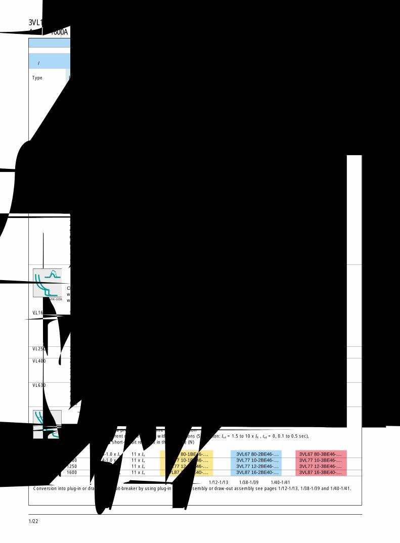
选型和订货数据 Selection and ordering data
3 极,630A 及以下 3-Pole, up to 630A
固定安装式断路器 /Fixed-mounted circuit-breakers热 /磁式过电流脱扣器 /Thermal/magnetic overcurrent releases
型号Type
NSK-1034
NSK-1035
NSK-1036
通过使用插入式插座组件或抽屉式组件可改装成插入式断路器或抽屉式断路器。见第 1/12-1/13 页、1/38-1/39 页和 1/40-1/41 页。Conversion into plug-in or draw-out circuit-breaker by using plug-in socket assembly or draw-out assembly see pages 1/12-1/13, 1/38-1/39 and 1/40-1/41.
3VL160X ~ VL630 断路器 3VL160X to VL630 Circuit-Breakers
线路保护用断路器,TM带可调整定值的热过载脱扣器,固定短路脱扣器Circuit-breakers for line protection, TMwith adjustable-thermal setting overload releases, fixed short-circuit releases
线路保护用断路器,TM带可调整定值的热过载脱扣器,可调短路脱扣器Circuit-breakers for line protection, TMwith adjustable-thermal setting overload releases, adjustable short-circuit releases
线路保护用断路器,TM带固定整定值的热过载脱扣器,固定短路脱扣器Circuit-breakers for line protection, TMwith fixed-setting thermal overload releases, fixed short-circuit releases
VL160X 16 16 300 3VL17 96-1DA33-.... 3VL17 96-2DA33-.... -20 20 300 3VL17 02-1DA33-.... 3VL17 02-2DA33-....25 25 300 3VL17 25-1DA33-.... 3VL17 25-2DA33-....32 32 300 3VL17 03-1DA33-.... 3VL17 03-2DA33-....40 40 600 3VL17 04-1DA33-.... 3VL17 04-2DA33-....50 50 600 3VL17 05-1DA33-.... 3VL17 05-2DA33-....63 63 600 3VL17 06-1DA33-.... 3VL17 06-2DA33-....80 80 1000 3VL17 08-1DA33-.... 3VL17 08-2DA33-....
100 100 1000 3VL17 10-1DA33-.... 3VL17 10-2DA33-....125 125 1000 3VL17 12-1DA33-.... 3VL17 12-2DA33-....160 160 1600 3VL17 16-1DA33-.... 3VL17 16-2DA33-....
VL160X 20 16-20 300 3VL17 02-1DD33-.... 3VL17 02-2DD33-.... -32 25-32 300 3VL17 03-1DD33-.... 3VL17 03-2DD33-....40 32-40 600 3VL17 04-1DD33-.... 3VL17 04-2DD33-....50 40-50 600 3VL17 05-1DD33-.... 3VL17 05-2DD33-....63 50-63 600 3VL17 06-1DD33-.... 3VL17 06-2DD33-....80 63-80 1000 3VL17 08-1DD33-.... 3VL17 08-2DD33-....
100 80-100 1000 3VL17 10-1DD33-.... 3VL17 10-2DD33-....125 100-125 1000 3VL17 12-1DD33-.... 3VL17 12-2DD33-....160 125-160 1600 3VL17 16-1DD33-.... 3VL17 16-2DD33-....
VL160 50 40-50 300-600 3VL27 05-1DC33-.... 3VL27 05-2DC33-.... 3VL27 05-3DC33-....63 50-63 300-600 3VL27 06-1DC33-.... 3VL27 06-2DC33-.... 3VL27 06-3DC33-....80 63-80 400-800 3VL27 08-1DC33-.... 3VL27 08-2DC33-.... 3VL27 08-3DC33-....
100 80-100 500-1000 3VL27 10-1DC33-.... 3VL27 10-2DC33-.... 3VL27 10-3DC33-....125 100-125 625-1250 3VL27 12-1DC33-.... 3VL27 12-2DC33-.... 3VL27 12-3DC33-....160 125-160 800-1600 3VL27 16-1DC33-.... 3VL27 16-2DC33-.... 3VL27 16-3DC33-....
VL250 200 160-200 1000-2000 3VL37 20-1DC36-.... 3VL37 20-2DC36-.... 3VL37 20-3DC36-....250 200-250 1200-2500 3VL37 25-1DC36-.... 3VL37 25-2DC36-.... 3VL37 25-3DC36-....
VL400 200 160-200 1000-2000 3VL47 20-1DC36-.... 3VL47 20-2DC36-.... 3VL47 20-3DC36-....250 200-250 1200-2500 3VL47 25-1DC36-.... 3VL47 25-2DC36-.... 3VL47 25-3DC36-....315 250-315 1575-3150 3VL47 31-1DC36-.... 3VL47 31-2DC36-.... 3VL47 31-3DC36-....400 315-400 2000-4000 3VL47 40-1DC36-.... 3VL47 40-2DC36-.... 3VL47 40-3DC36-....
VL630 315 250-315 1575-3150 3VL57 31-1DC36-.... 3VL57 31-2DC36-.... 3VL57 31-3DC36-....400 315-400 2000-4000 3VL57 40-1DC36-.... 3VL57 40-2DC36-.... 3VL57 40-3DC36-....500 400-500 2500-5000 3VL57 50-1DC36-.... 3VL57 50-2DC36-.... 3VL57 50-3DC36-....630 500-630 3250-6500 3VL57 63-1DC36-.... 3VL57 63-2DC36-.... 3VL57 63-3DC36-....

1/17
13 极,800A 及以下 3-Pole, up to 800A选型和订货数据 Selection and ordering data
NSK-1037
NSK-1038
NSK-1039
固定安装式断路器 /Fixed-mounted circuit-breakers电磁式和电子式过电流脱扣器 /Magnetic and electronic overcurrent releases
型号Type
额定电流RatedcurrentIn
A
过载反时限脱扣器“L”的整定电流Settingcurrent ofinverse-timedelayedoverloadrelease "L"IR
A
短路瞬时脱扣器“I”的整定电流Operatingcurrent ofcurrent ofinstantaneousshort-circuitrelease "I"Ii
A
标准分断能力N40/45/50kA,在 380/415V AC 时见第 1/60 页Standard switching capacity N40/45/50 kA at 380/415 V ACsee page 1/60.订货号根据第 1/30 页和第 1/31 页所需的订货号后缀Order No.Order No. supplementrequired according topages 1/30 and 1/31
3VL160 ~ VL800 断路器 3VL160 to VL800 Circuit-Breakers
高分断能力H70kA,在 380/415V AC 时High switching capacity H70 kA at 380/415 V AC
订货号根据第 1/30 页和第 1/31 页所需的订货号后缀Order No.Order No. supplementrequired according topages 1/30 and 1/31
电动机 /发电机保护用断路器带电子式过电流脱扣器 ETU10M,固定时滞等级为 TR = 10,断相敏感Circuit-breakers for motor/generator protectionwith electronic overcurrent release ETU10M, with fixed trip class TR = 10, with sensitivity to phase failure
电动机 /发电机保护用断路器,带电子式过电流脱扣器 LCD ETU40M,可调时滞等级为 TR (5, 10, 15, 20, 30),断相敏感Circuit breakers for motor/generator protectionwith electronic overcurrent release LCD ETU40M, with adjustable trip class TR (5,10,15, 20, 30), with sensitivity to phase failure
带电磁式过电流脱扣器的起动器组合用断路器Circuit-breakers for starter combinations with magnetic overcurrent release
极高分断能力 L100kA,在 380/415V AC 时Very high switching capacity L100 kA at 380/415 V AC
订货号根据第 1/30 页和第 1/31 页所需的订货号后缀Order No.Order No. supplementrequired according topages 1/30 and 1/31
VL160 63 25-63 1.25-11 x In 3VL27 06-1AP33-.... 3VL27 06-2AP33-.... 3VL27 06-3AP33-....
100 40-100 1.25-11 x In 3VL27 10-1AP33-.... 3VL27 10-2AP33-.... 3VL27 10-3AP33-....
160 64-160 1.25-11 x In 3VL27 16-1AP33-.... 3VL27 16-2AP33-.... 3VL27 16-3AP33-....
VL250 200 80-200 1.25-11 x In 3VL37 20-1AP36-.... 3VL37 20-2AP36-.... 3VL37 20-3AP36-....
250 100-250 1.25-11 x In 3VL37 25-1AP36-.... 3VL37 25-2AP36-.... 3VL37 25-3AP36-....
VL400 400 150-400 1.25-11 x In 3VL47 40-1AP36-.... 3VL47 40-2AP36-.... 3VL47 40-3AP36-....
VL630 630 252-630 1.25-11 x In 3VL57 63-1AP36-.... 3VL57 63-2AP36-.... 3VL57 63-3AP36-....
VL160 63 25-63 1.25-11 x In 3VL27 06-1CP33-.... 3VL27 06-2CP33-.... 3VL27 06-3CP33-....
100 40-100 1.25-11 x In 3VL27 10-1CP33-.... 3VL27 10-2CP33-.... 3VL27 10-3CP33-....
160 64-160 1.25-11 x In 3VL27 16-1CP33-.... 3VL27 16-2CP33-.... 3VL27 16-3CP33-....
VL250 200 80-200 1.25-11 x In 3VL37 20-1CP36-.... 3VL37 20-2CP36-.... 3VL37 20-3CP36-....
250 100-250 1.25-11 x In 3VL37 25-1CP36-.... 3VL37 25-2CP36-.... 3VL37 25-3CP36-....
VL400 400 160-400 1.25-11 x In 3VL47 40-1CP36-.... 3VL47 40-2CP36-.... 3VL47 40-3CP36-....
VL630 630 252-630 1.25-11 x In 3VL57 63-1CP36-.... 3VL57 63-2CP36-.... 3VL57 63-3CP36-....
VL160 至 /up to 63 - 450-900 3VL27 06-1DK33-.... 3VL27 06-2DK33-.... 3VL27 06-3DK33-....
至 /up to 100 - 750-1500 3VL27 10-1DK33-.... 3VL27 10-2DK33-.... 3VL27 10-3DK33-....
至 /up to 160 - 1250-2500 3VL27 16-1DK33-.... 3VL27 16-2DK33-.... 3VL27 16-3DK33-....
VL250 至 /up to 250 - 2000-4000 3VL37 25-1DK36-... 3VL37 25-2DK36-.... 3VL37 25-3DK36-....
VL400 至 /up to 200 - 1250-2500 3VL47 20-1DK36-.... 3VL47 20-2DK36-.... 3VL47 20-3DK36-....
至 /up to 250 - 2000-4000 3VL47 25-1DK36-.... 3VL47 25-2DK36-.... 3VL47 25-3DK36-....
至 /up to 400 - 3000-6000 3VL47 40-1DK36-.... 3VL47 40-2DK36-.... 3VL47 40-3DK36-....
VL630 至 /up to 315 - 2000-4000 3VL57 31-1DK36-.... 3VL57 31-2DK36-.... 3VL57 31-3DK36-....
至 /up to 630 - 3250-6500 3VL57 63-1DK36-.... 3VL57 63-2DK36-.... 3VL57 63-3DK36-....
VL800 至 /up to 800 - 3250-6500 3VL67 80-1DK36-.... 3VL67 80-2DK36-.... 3VL67 80-3DK36-....
通过使用插入式插座组件或抽屉式组件可改装成插入式断路器或抽屉式断路器。见第 1/12-1/13 页、1/38-1/39 页和 1/40-1/41 页。Conversion into plug-in or draw-out circuit-breaker by using plug-in socket assembly or draw-out assembly see pages 1/12-1/13, 1/38-1/39 and 1/40-1/41.
1/18
选型和订货数据 Selection and ordering data
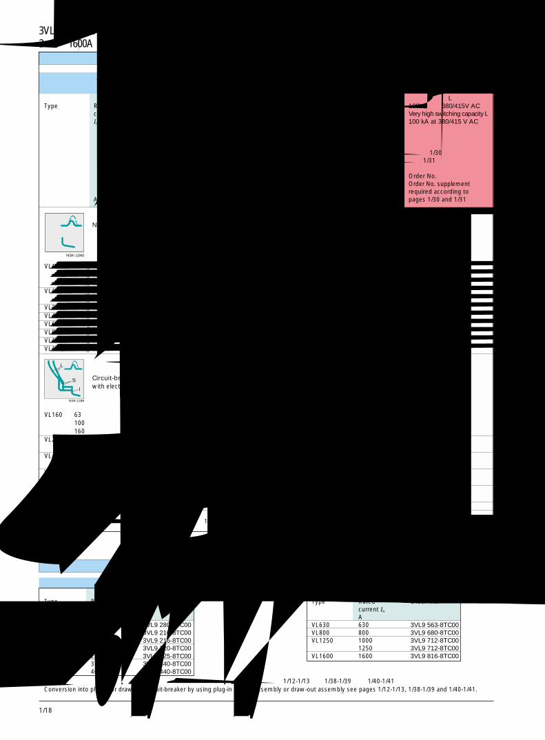
3 极,1600A 及以下 3-Pole, up to 1600A
固定安装式断路器 /Fixed-mounted circuit-breakers电磁式和电子式过电流脱扣器 /Magnetic and electronic overcurrent releases
型号Type
额定电流RatedcurrentIn
A
过载反时限脱扣器“L”的整定电流Settingcurrent ofinverse-timedelayedoverloadrelease "L"IR
A
短路瞬时脱扣器“I”的整定电流Operatingcurrent ofcurrent ofinstantaneousshort-circuitrelease "I"Ii
A
标准分断能力N40/45/50kA,在 380/415V AC 时见第 1/60 页Standard switching capacity N40/45/50 kA at 380/415 V ACsee page 1/60.订货号根据第 1/30 页和第 1/31 页所需的订货号后缀Order No.Order No. supplementrequired according topages 1/30 and 1/31
高分断能力H70kA,在 380/415V AC 时High switching capacity H70 kA at 380/415 V AC
订货号根据第 1/30 页和第 1/31 页所需的订货号后缀Order No.Order No. supplementrequired according topage 1/30 and 1/31
3VL160X ~ VL1600 断路器 3VL160X to VL1600 Circuit-Breakers
NSK-1040
带电磁式过电流的隔离开关Non-automatic circuit-breakers with magnetic overcurrent release
NSK-1188
L
S
I
线路保护用断路器,用于时间选择性带电子式过电流脱扣器 ETU20,带 LSI 功能 (S 功能:Isd = 1.5~10 IR,tsd = 0, 0.1~0.5s)Circuit-breakers for line protection, for time discriminationwith electronic overcurrent release ETU20, with LSI functions (S-function: Isd = 1.5 to 10 x IR , tsd = 0, 0.1 to 0.5 sec)
有关短路和 / 或接地故障保护用的其他类型断路器,见第 1/19-1/20 页 /Further versions also for short-circuit and/or earth fault protection, see page 1/19-1/20.
附件 Accessories
型号 额定电流 订货号Type Rated Order No.
current In
AVL160 63 3VL9 280-8TC00
100 3VL9 210-8TC00160 3VL9 216-8TC00
VL250 200 3VL9 320-8TC00250 3VL9 325-8TC00
VL400 315 3VL9 440-8TC00400 3VL9 440-8TC00
类型 额定电流 订货号Type Rated Order No.
current In
AVL630 630 3VL9 563-8TC00VL800 800 3VL9 680-8TC00VL1250 1000 3VL9 712-8TC00
1250 3VL9 712-8TC00VL1600 1600 3VL9 816-8TC00
用于三相四线系统中 N 极用于接地故障保护的电流互感器 /Current transformers for N-conductor for earth fault protection in 3-phase 4-wire systems
通过使用插入式插座组件或抽屉式组件可改装成插入式断路器或抽屉式断路器。见第 1/12-1/13 页、1/38-1/39 页和 1/40-1/41 页。Conversion into plug-in or draw-out circuit-breaker by using plug-in socket assembly or draw-out assembly see pages 1/12-1/13, 1/38-1/39 and 1/40-1/41.
极高分断能力 L100kA,在 380/415V AC 时Very high switching capacity L100 kA at 380/415 V AC
订货号根据第 1/30 页和第 1/31 页所需的订货号后缀Order No.Order No. supplementrequired according topages 1/30 and 1/31
VL160X 至 /up to 100 - 2500 3VL17 10-1DE33-.... 3VL17 10-2DE33-.... -至 /up to 125 - 3000 3VL17 12-1DE33-.... 3VL17 12-2DE33-....至 /up to 160 - 3000 3VL17 16-1DE33-.... 3VL17 16-2DE33-....
VL160 至 /up to 100 - 2500 3VL27 10-1DE33-.... 3VL27 10-2DE33-.... 3VL27 10-3DE33-....至 /up to 160 - 2500 3VL27 16-1DE33-.... 3VL27 16-2DE33-.... 3VL27 16-3DE33-....
VL250 至 /up to 250 - 4000 3VL37 25-1DE36-.... 3VL37 25-2DE36-.... 3VL37 25-3DE36-....VL400 至 /up to 400 - 6000 3VL47 40-1DE36-.... 3VL47 40-2DE36-.... 3VL47 40-3DE36-....VL630 至 /up to 630 - 6500 3VL57 63-1DE36-.... 3VL57 63-2DE36-.... 3VL57 63-3DE36-....VL800 至 /up to 800 - 8000 3VL67 80-1DE36-.... 3VL67 80-2DE36-.... 3VL67 80-3DE36-....VL1250 至 /up to 1250 - 12000 3VL77 12-1DE36-.... 3VL77 12-2DE36-.... 3VL77 12-3DE36-....VL1600 至 /up to 1600 - 16000 3VL87 16-1DE30-.... 3VL87 16-2DE30-.... 3VL87 16-3DE30-....
VL160 63 0.4 - 1.0 x In 11 x In 3VL27 06-1AE33-.... 3VL27 06-2AE33-.... 3VL27 06-3AE33-....100 0.4 - 1.0 x In 11 x In 3VL27 10-1AE33-.... 3VL27 10-2AE33-.... 3VL27 10-3AE33-....160 0.4-1.0 x In 11 x In 3VL27 16-1AE33-.... 3VL27 16-2AE33-.... 3VL27 16-3AE33-....
VL250 200 0.4-1.0 x In 11 x In 3VL37 20-1AE36-.... 3VL37 20-2AE36-.... 3VL37 20-3AE36-....250 0.4-1.0 x In 11 x In 3VL37 25-1AE36-.... 3VL37 25-2AE36-.... 3VL37 25-3AE36-....
VL400 315 0.4-1.0 x In 11 x In 3VL47 31-1AE36-.... 3VL47 31-2AE36-.... 3VL47 31-3AE36-....400 0.4-1.0 x In 11 x In 3VL47 40-1AE36-.... 3VL47 40-2AE36-.... 3VL47 40-3AE36-....
VL630 630 0.4-1.0 x In 11 x In 3VL57 63-1AE36-.... 3VL57 63-2AE36-.... 3VL57 63-3AE36-....VL800 800 0.4-1.0 x In 11 x In 3VL67 80-1AE36-.... 3VL67 80-2AE36-.... 3VL67 80-3AE36-....VL1250 1000 0.4-1.0 x In 11 x In 3VL77 10-1AE36-.... 3VL77 10-2AE36-.... 3VL77 10-3AE36-....
1250 0.4-1.0 x In 11 x In 3VL77 12-1AE36-.... 3VL77 12-2AE36-.... 3VL77 12-3AE36-....VL1600 1600 0.4-1.0 x In 11 x In 3VL87 16-1AE30-.... 3VL87 16-2AE30-.... 3VL87 16-3AE30-....
1/19
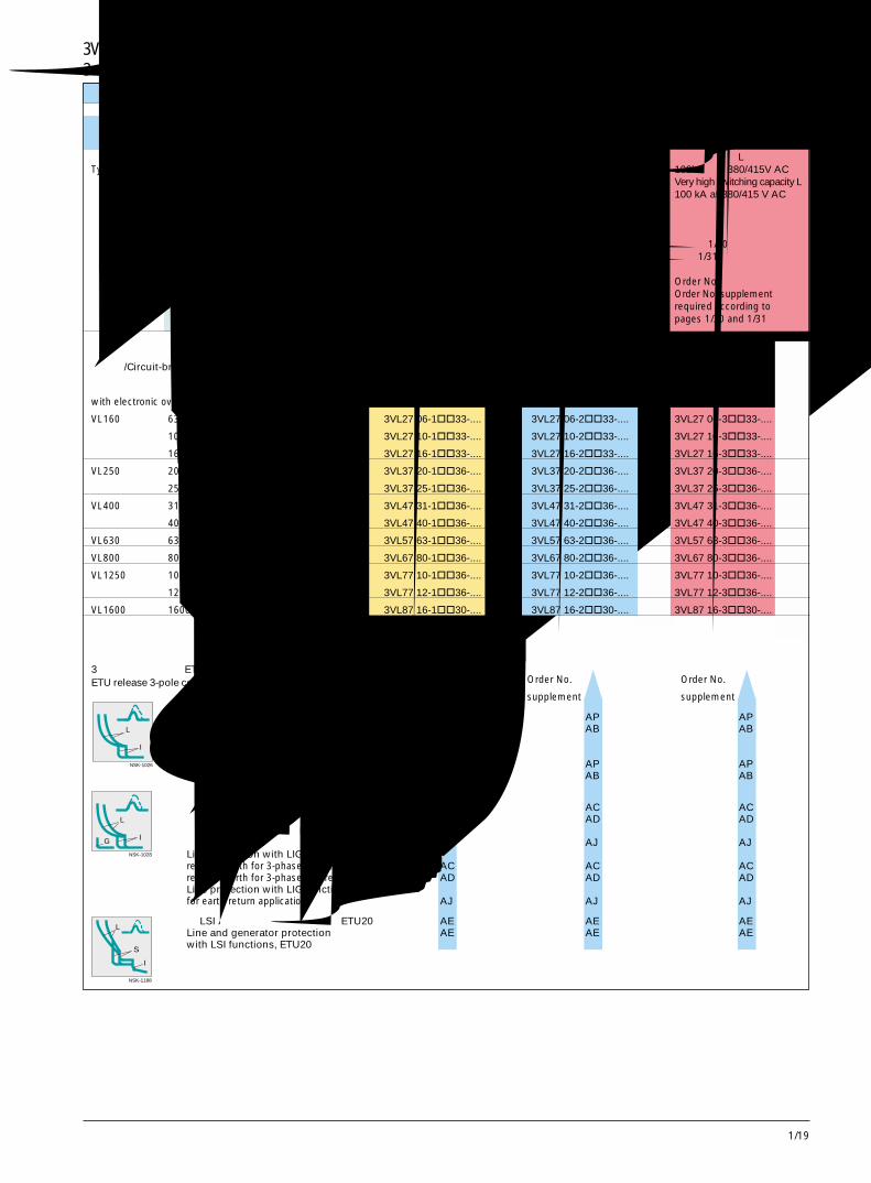
13 极,1600A 及以下 3-Pole, up to 1600A选型和订货数据 Selection and ordering data
固定安装式断路器 /Fixed-mounted circuit-breakers电子式过电流脱扣器 /Electronic overcurrent releases
型号Type
额定电流RatedcurrentIn
A
过载反时限脱扣器“L”的整定电流Setting current ofinverse-time delayedoverload release "L"IR
A
标准分断能力N40/45/50kA,在 380/415V AC 时见第 1/60 页Standard switching capacity N40/45/50 kA at 380/415 V ACsee page 1/60.订货号根据第 1/30 页和第 1/31 页所需的订货号后缀Order No.Order No. supplementrequired according topages 1/30 and 1/31
高分断能力H70kA,在 380/415V AC 时High switching capacity H70 kA at 380/415 V AC
订货号根据第 1/30 页和第 1/31 页所需的订货号后缀Order No.Order No. supplementrequired according topages 1/30 and 1/31
3 极断路器的脱扣器 ETUETU release 3-pole construction
NSK-1026
L
I
NSK-1028
L
IG
NSK-1188
L
S
I
带 LI 功能的电动机 /发电机保护,ETU10M63~630A (VL160~VL630) AP AP AP带 LI功能的线路保护,ETU10 AB AB ABMotor/generator protection withLI functions, ETU10Mfrom 63 to 630A (VL160~VL630) AP AP APLine protection with LI functions, ETU10 AB AB AB
带 LIG功能的线路保护,ETU12接地保护用于 3 相 3 线系统 AC AC AC接地保护用于 3 相 4 线系统 AD AD AD带 LIG功能的线路保护,ETU12用于直接测量接地电流 AJ AJ AJLine protection with LIG functions, ETU12residual earth for 3-phase 3-wire systems AC AC ACresidual earth for 3-phase 4-wire systems AD AD ADLine protection with LIG functions, ETU12for earth return applications AJ AJ AJ
带 LSI 功能的线路和发电机保护,ETU20 AE AE AELine and generator protection AE AE AEwith LSI functions, ETU20
3VL160 ~ VL1600 断路器 3VL160 to VL1600 Circuit-Breakers
极高分断能力 L100kA,在 380/415V AC 时Very high switching capacity L100 kA at 380/415 V AC
订货号根据第 1/30 页和第 1/31 页所需的订货号后缀Order No.Order No. supplementrequired according topages 1/30 and 1/31
断路器 /Circuit-breakers
带电子式过电流脱扣器 ETU
with electronic overcurrent release ETU
VL160 63 25-63 3VL27 06-1��33-.... 3VL27 06-2��33-.... 3VL27 06-3��33-....
100 40-100 3VL27 10-1��33-.... 3VL27 10-2��33-.... 3VL27 10-3��33-....
160 64-160 3VL27 16-1��33-.... 3VL27 16-2��33-.... 3VL27 16-3��33-....
VL250 200 80-200 3VL37 20-1��36-.... 3VL37 20-2��36-.... 3VL37 20-3��36-....
250 100-250 3VL37 25-1��36-.... 3VL37 25-2��36-.... 3VL37 25-3��36-....
VL400 315 128-315 3VL47 31-1��36-.... 3VL47 31-2��36-.... 3VL47 31-3��36-....
400 160-400 3VL47 40-1��36-.... 3VL47 40-2��36-.... 3VL47 40-3��36-....
VL630 630 252-630 3VL57 63-1��36-.... 3VL57 63-2��36-.... 3VL57 63-3��36-....
VL800 800 320-800 3VL67 80-1��36-.... 3VL67 80-2��36-.... 3VL67 80-3��36-....
VL1250 1000 400-1000 3VL77 10-1��36-.... 3VL77 10-2��36-.... 3VL77 10-3��36-....
1250 500-1250 3VL77 12-1��36-.... 3VL77 12-2��36-.... 3VL77 12-3��36-....
VL1600 1600 640-1600 3VL87 16-1��30-.... 3VL87 16-2��30-.... 3VL87 16-3��30-....
订货号后缀 订货号后缀 订货号后缀
Order No. Order No. Order No.
supplement supplement supplement
1/20
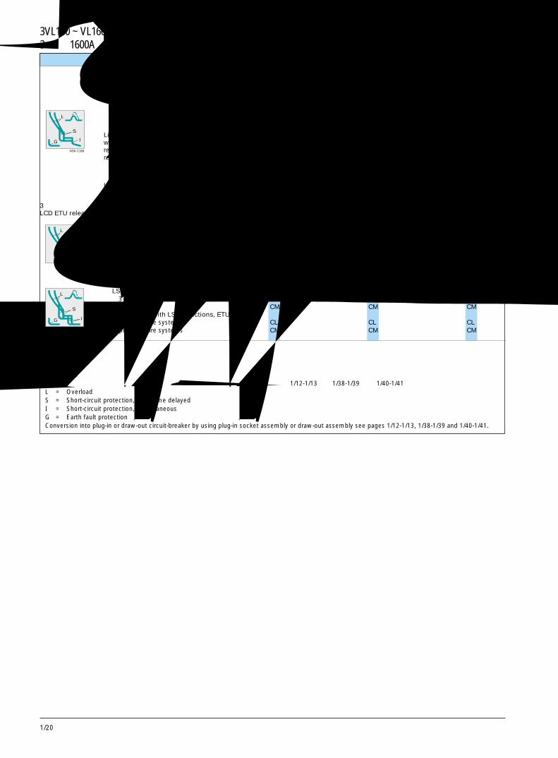
L = 过载长延时S = 短路短延时保护I = 短路瞬时保护G = 接地故障保护通过使用插入式插座组件或抽屉式组件可改装成插入式断路器或抽屉式断路器。见第 1/12-1/13 页、1/38-1/39 页和 1/40-1/41 页。L = OverloadS = Short-circuit protection, short-time delayedI = Short-circuit protection, instantaneousG = Earth fault protectionConversion into plug-in or draw-out circuit-breaker by using plug-in socket assembly or draw-out assembly see pages 1/12-1/13, 1/38-1/39 and 1/40-1/41.
NSK-1190
L
S
I
NSK-1444
L
S
IG
带 LSIG 功能的线路和发电机保护,ETU22接地保护用于 3 相 3 线系统 AG AG AG接地保护用于 3 相 4 线系统 AH AH AHLine and generator protectionwith LSIG functions, ETU22residual earth for 3-phase 3-wire systems AG AG AGresidual earth for 3-phase 4-wire systems AH AH AH
带 LSIG 功能的线路和发电机保护,ETU22 AK AK AK用于接地回路应用Line and generator protection AK AK AKwith LSIG functions, ETU22
3 极断路器的脱扣器 LCD ETULCD ETU release 3-pole construction
带 LI 功能的电动机 /发电机保护,ETU40M (至VL630) CP C P CP带 LI/LS/LSI 功能的线路保护,ETU40 CH CH CHMotor/generator protection withLI functions, ETU40M (to VL630) CP CP CPLIne protection with LI/LS/LSIfunctions, ETU40 CH CH CH
带 LSIG 功能的线路保护,ETU42用于 3 相 3 线系统 CL CL CL用于 3 相 4 线系统 CM CM CMLine protection with LSIG functions, ETU42for 3-phase 3-wire systems CL CL CLfor 3-phase 4-wire systems CM CM CM
选型和订货数据 Selection and ordering data
3 极,1600A 及以下 3-Pole, up to 1600A
NSK-1189
L
S
IG
订货号后缀 订货号后缀 订货号后缀
Order No. Order No. Order No.supplement supplement supplement
3VL160 ~ VL1600 断路器 3VL160 to VL1600 Circuit-Breakers
1/21
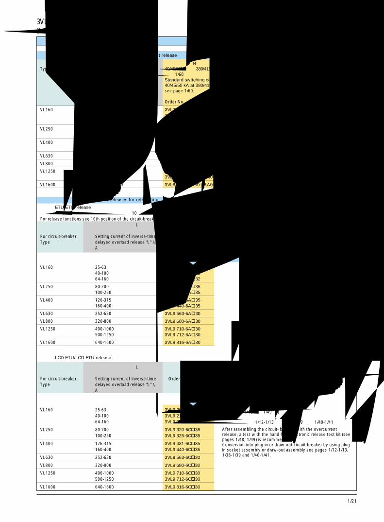
1选型和订货数据 Selection and ordering data
3 极,1600A 及以下 3-Pole, up to 1600A
不带过电流脱扣器的断路器 /-breakers without overcurrent release
型号Type
过载反时限脱扣器“L”的整定电流Setting current ofinverse-time delayedoverload release "L"IR
A
标准分断能力N40/45/50kA,在 380/415V AC 时见第 1/60 页Standard switching capacity N40/45/50 kA at 380/415 V ACsee page 1/60.订货号Order No.
高分断能力H70kA,在 380/415V AC 时High switching capacity H70 kA at 380/415 V AC
订货号Order No.
极高分断能力 L100kA,在 380/415V AC 时Very high switching capacity L100 kA at 380/415 V AC
订货号Order No.
VL160 25-63 3VL27 16-1AA31-0AA0 3VL27 16-2AA31-0AA0 3VL27 16-3AA31-0AA040-100 3VL27 16-1AA31-0AA0 3VL27 16-2AA31-0AA0 3VL27 16-3AA31-0AA064-160 3VL27 16-1AA31-0AA0 3VL27 16-2AA31-0AA0 3VL27 16-3AA31-0AA0
VL250 80-200 3VL37 25-1AA34-0AA0 3VL37 25-2AA34-0AA0 3VL37 25-3AA34-0AA0100-250 3VL37 25-1AA34-0AA0 3VL37 25-2AA34-0AA0 3VL37 25-3AA34-0AA0
VL400 126-315 3VL47 40-1AA34-0AA0 3VL47 40-2AA34-0AA0 3VL47 40-3AA34-0AA0160-400 3VL47 40-1AA34-0AA0 3VL47 40-2AA34-0AA0 3VL47 40-3AA34-0AA0
VL630 252-630 3VL57 63-1AA36-0AA0 3VL57 63-2AA36-0AA0 3VL57 63-3AA36-0AA0
VL800 320-800 3VL67 80-1AA36-0AA0 3VL67 80-2AA36-0AA0 3VL67 80-3AA36-0AA0
VL1250 400-1000 3VL77 12-1AA36-0AA0 3VL77 12-2AA36-0AA0 3VL77 12-3AA36-0AA0500-1250 3VL77 12-1AA36-0AA0 3VL77 12-2AA36-0AA0 3VL77 12-3AA36-0AA0
VL1600 640-1600 3VL87 16-1AA30-0AA0 3VL87 16-2AA30-0AA0 3VL87 16-3AA30-0AA0
功能
function
P B C D J E G H K
改装用过电流脱扣器 /Overcurrent releases for retrofitting
脱扣器 ETU/ETU release有关脱扣器功能,参见上页断路器订货号的第 10 个位置。For release functions see 10th position of the circuit-breaker Order No. on previous page.用于断路器型号 过载反时限脱扣器“L” 订货号
的整定电流For circuit-breaker Setting current of inverse-time Order No.Type delayed overload release "L" IR
A
VL160 25-63 3VL9 206-6A�3240-100 3VL9 210-6A�3264-160 3VL9 216-6A�32
VL250 80-200 3VL9 320-6A�35100-250 3VL9 325-6A�35
VL400 126-315 3VL9 431-6A�35160-400 3VL9 440-6A�35
VL630 252-630 3VL9 563-6A�30
VL800 320-800 3VL9 680-6A�30
VL1250 400-1000 3VL9 710-6A�30500-1250 3VL9 712-6A�30
VL1600 640-1600 3VL9 816-6A�30
3VL160 ~ VL1600 断路器 3VL160 to VL1600 Circuit-Breakers
P H L M
功能
function
脱扣器 LCD ETU/LCD ETU release
用于断路器型号 过载反时限脱扣器“L” 订货号的整定电流
For circuit-breaker Setting current of inverse-time Order No.Type delayed overload release "L" IR
A
VL160 25-63 3VL9 206-6C�3240-100 3VL9 210-6C�3264-160 3VL9 216-6C�32
VL250 80-200 3VL9 320-6C�35100-250 3VL9 325-6C�35
VL400 126-315 3VL9 431-6C�35160-400 3VL9 440-6C�35
VL630 252-630 3VL9 563-6C�30
VL800 320-800 3VL9 680-6C�30
VL1250 400-1000 3VL9 710-6C�30500-1250 3VL9 712-6C�30
VL1600 640-1600 3VL9 816-6C�30
在组装带过电流脱扣器的断路器之后,应使用手持电子式脱扣器测试元件 (见第 1/48 页,1/49 页) 进行测试。通过使用插入式插座组件或抽屉式组件可改装成插入式断路器或抽屉式断路器。见第 1/12-1/13 页、1/38-1/39 页和 1/40-1/41 页。
After assembling the circuit- breaker with the overcurrentrelease, a test with the hand held electronic release test kit (seepages 1/48, 1/49) is recommended.Conversion into plug-in or draw-out circuit-breaker by using plug-in socket assembly or draw-out assembly see pages 1/12-1/13,1/38-1/39 and 1/40-1/41.
1/22
NSK-1034
选型和订货数据 Selection and ordering data
4 极,1600A 及以下 4-Pole, up to 1600A
固定安装式断路器 /Fixed-mounted circuit-breakers热 /磁式和电子式过电流脱扣器 /Thermal/magnetic and electronic overcurrent releases
型号Type
额定电流RatedcurrentIn
A
过载反时限脱扣器“L”的整定电流Settingcurrent ofinverse-timedelayedoverloadrelease "L"IR
A
短路瞬时脱扣器“I”的整定电流Operatingcurrent ofcurrent ofinstantaneousshort-circuitrelease "I"Ii
A
标准分断能力 N40/45/50kA,在 380/415V AC 时见第 1/60 页Standard switching capacity N40/45/50 kA at 380/415 V ACsee page 1/60.订货号根据第 1/30 页和第 1/31 页所需的订货号后缀Order No.Order No. supplementrequired according topages 1/30 and 1/31
通过使用插入式插座组件或抽屉式组件可改装成插入式断路器或抽屉式断路器。见第 1/12-1/13 页、1/38-1/39 页和 1/40-1/41 页。Conversion into plug-in or draw-out circuit-breaker by using plug-in socket assembly or draw-out assembly see pages 1/12-1/13, 1/38-1/39 and 1/40-1/41.
3VL160X ~ VL1600 断路器 3VL160X to VL1600 Circuit-Breakers
高分断能力 H70kA,在 380/415V AC 时High switching capacity H70 kA at 380/415 V AC
订货号根据第 1/30 页和第 1/31 页所需的订货号后缀Order No.Order No. supplementrequired according topages 1/30 and 1/31
线路保护用断路器,TM带固定整定值的热过载脱扣器,固定短路脱扣器,在第 4 极 (N) 中不带过载和短路脱扣器Circuit-breakers for line protection, TMwith fixed-setting thermal overload releases, fixed short-circuit releases,without overload and short-circuit releases in the 4th pole (N)
NSK-1036
L
S
I
NSK-1041
线路保护用断路器,TM带可调整定值的热过载脱扣器,可调短路脱扣器,在第 4 极 (N) 中不带过载和短路脱扣器Circuit-breakers for line protection, TMwith adjustable thermal setting overload releases, adjustable short-circuit releases,without overload and short-circuit releases in the 4th pole (N)
线路保护用断路器,用于时间选择性带电子式过电流脱扣器 ETU20,带 LSI 功能 (S 功能:Isd = 1.5~10 x IR, tsd = 0, 0.1~0.5s)在第 4 极 (N) 中不带过载和短路脱扣器Circuit-breakers for line protection, for time discriminationwith electronic overcurrent release ETU20, with LSI functions (S-function: Isd = 1.5 to 10 x IR , tsd = 0, 0.1 to 0.5 sec),without overload and short-circuit releases in the 4th pole (N)
极高分断能力 L100kA,在 380/415V AC 时Very high switching capacity L100 kA at 380/415 V AC
订货号根据第 1/30 页和第 1/31 页所需的订货号后缀Order No.Order No. supplementrequired according topages 1/30 and 1/31
VL160X 16 16 300 3VL17 96-1EH43-.... 3VL17 96-2EH43-.... -20 20 300 3VL17 02-1EH43-.... 3VL17 02-2EH43-....25 25 300 3VL17 25-1EH43-.... 3VL17 25-2EH43-....32 32 300 3VL17 03-1EH43-.... 3VL17 03-2EH43-....40 40 600 3VL17 04-1EH43-.... 3VL17 04-2EH43-....50 50 600 3VL17 05-1EH43-.... 3VL17 05-2EH43-....63 63 600 3VL17 06-1EH43-.... 3VL17 06-2EH43-....80 80 1000 3VL17 08-1EH43-.... 3VL17 08-2EH43-....100 100 1000 3VL17 10-1EH43-.... 3VL17 10-2EH43-....125 125 1000 3VL17 12-1EH43-.... 3VL17 12-2EH43-....160 160 1600 3VL17 16-1EH43-.... 3VL17 16-2EH43-....
VL160 50 40-50 300-600 3VL27 05-1EJ43-.... 3VL27 05-2EJ43-.... 3VL27 05-3EJ43-....63 50-63 300-600 3VL27 06-1EJ43-.... 3VL27 06-2EJ43-.... 3VL27 06-3EJ43-....80 63-80 400-800 3VL27 08-1EJ43-.... 3VL27 08-2EJ43-.... 3VL27 08-3EJ43-....100 80-100 500-1000 3VL27 10-1EJ43-.... 3VL27 10-2EJ43-.... 3VL27 10-3EJ43-....125 100-125 625-1250 3VL27 12-1EJ43-.... 3VL27 12-2EJ43-.... 3VL27 12-3EJ43-....160 125-160 800-1600 3VL27 16-1EJ43-.... 3VL27 16-2EJ43-.... 3VL27 16-3EJ43-....
VL250 200 160-200 1000-2000 3VL37 20-1EJ46-.... 3VL37 20-2EJ46-.... 3VL37 20-3EJ46-....250 200-250 1250-2500 3VL37 25-1EJ46-.... 3VL37 25-2EJ46-.... 3VL37 25-3EJ46-....
VL400 200 160-200 1000-2000 3VL47 20-1EJ46-.... 3VL47 20-2EJ46-.... 3VL47 20-3EJ46-....250 200-250 1250-2500 3VL47 25-1EJ46-.... 3VL47 25-2EJ46-.... 3VL47 25-3EJ46-....315 250-315 1575-3150 3VL47 32-1EJ46-.... 3VL47 32-2EJ46-.... 3VL47 32-3EJ46-....400 320-400 2000-4000 3VL47 40-1EJ46-.... 3VL47 40-2EJ46-.... 3VL47 40-3EJ46-....
VL630 315 200-315 1575-3150 3VL57 32-1EJ46-.... 3VL57 32-2EJ46-.... 3VL57 32-3EJ46-....400 320-400 2000-4000 3VL57 40-1EJ46-.... 3VL57 40-2EJ46-.... 3VL57 40-3EJ46-....500 400-500 2500-5000 3VL57 50-1EJ46-.... 3VL57 50-2EJ46-.... 3VL57 50-3EJ46-....630 500-630 3250-6500 3VL57 63-1EJ46-.... 3VL57 63-2EJ46-.... 3VL57 63-3EJ46-....
VL800 800 0.4-1.0 x In 11 x In 3VL67 80-1BE46-.... 3VL67 80-2BE46-.... 3VL67 80-3BE46-....VL1250 1000 0.4-1.0 x In 11 x In 3VL77 10-1BE46-.... 3VL77 10-2BE46-.... 3VL77 10-3BE46-....
1250 0.4-1.0 x In 11 x In 3VL77 12-1BE46-.... 3VL77 12-2BE46-.... 3VL77 12-3BE46-....VL1600 1600 0.4-1.0 x In 11 x In 3VL87 16-1BE40-.... 3VL87 16-2BE40-.... 3VL87 16-3BE40-....
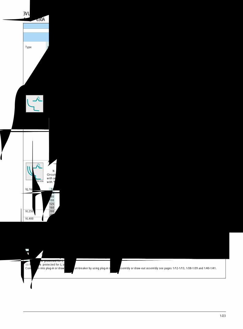
1/23
14 极,630A 及以下 4-Pole, up to 630A选型和订货数据 Selection and ordering data
固定安装式断路器 /Fixed-mounted circuit-breakers热磁式过电流脱扣器 /Thermal/magnetic overcurrent releases
型号Type
额定电流RatedcurrentIn
A
过载反时限脱扣器“L”的整定电流Settingcurrent ofinverse-timedelayedoverloadrelease "L"IR
A
短路瞬时脱扣器“I”的整定电流Operatingcurrent ofcurrent ofinstantaneousshort-circuitrelease "I"Ii
A
标准分断能力 N40/45/50kA,在 380/415V AC 时见第 1/60 页Standard switching capacity N40/45/50 kA at 380/415 V ACsee page 1/60.订货号根据第 1/30 页和第 1/31 页所需的订货号后缀Order No.Order No. supplementrequired according topages 1/30 and 1/31
高分断能力H70kA,在 380/415V AC 时High switching capacity H70 kA at 380/415 V AC
订货号根据第 1/30 页和第 1/31 页所需的订货号后缀Order No.Order No. supplementrequired according topages 1/30 and 1/31
N = 针对 In ≤ 100A 提供 100% 保护N = 针对 In ≥ 125A 提供 60% 保护
通过使用插入式插座组件或抽屉式组件可改装成插入式断路器或抽屉式断路器。见第 1/12-1/13 页、1/38-1/39 页和 1/40-1/41 页。N = 100 % protected for In ≤100AN = 60 % protected for In ≥125 A
Conversion into plug-in or draw-out circuit-breaker by using plug-in socket assembly or draw-out assembly see pages 1/12-1/13, 1/38-1/39 and 1/40-1/41.
3VL160X ~ VL630 断路器 3VL160X to VL630 Circuit-Breakers
NSK-1034
NSK-1036
线路保护用断路器,TM带固定整定值的热过载脱扣器,固定短路脱扣器,带“N”过载和短路脱扣器Circuit-breakers for line protection, TMwith fixed-setting thermal overload release, fixed short-circuit releases,with "N" overload and short-circuit release
VL160X 16 16 300 3VL17 96-1EA43-.... 3VL17 96-2EA43-.... -20 20 300 3VL17 02-1EA43-.... 3VL17 02-2EA43-....25 25 300 3VL17 25-1EA43-.... 3VL17 25-2EA43-....32 32 300 3VL17 03-1EA43-.... 3VL17 03-2EA43-....40 40 600 3VL17 04-1EA43-.... 3VL17 04-2EA43-....50 50 600 3VL17 05-1EA43-.... 3VL17 05-2EA43-....63 63 600 3VL17 06-1EA43-.... 3VL17 06-2EA43-....80 80 1000 3VL17 08-1EA43-.... 3VL17 08-2EA43-....
100 100 1000 3VL17 10-1EA43-.... 3VL17 10-2EA43-....125 125 1000 3VL17 12-1EA43-.... 3VL17 12-2EA43-....160 160 1600 3VL17 16-1EA43-.... 3VL17 16-2EA43-....
线路保护用断路器,TM带可调热整定值的过载脱扣器,可调短路脱扣器,带“N”过载和短路脱扣器Circuit-breakers for line protection, TMwith adjustable thermal setting overload release, adjustable short-circuit releases,with "N" overload and short-circuit releases
极高分断能力 L100kA,在 380/415V AC 时Very high switching capacity L100 kA at 380/415 V AC
订货号根据第 1/30 页和第 1/31 页所需的订货号后缀Order No.Order No. supplementrequired according topages 1/30 and 1/31
VL160 50 40-50 300-600 3VL27 05-1EC43-... 3VL27 05-2EC43-.... 3VL27 05-3EC43-....63 50-63 300-600 3VL27 06-1EC43-.... 3VL27 06-2EC43-.... 3VL27 06-3EC43-....80 63-80 400-800 3VL27 08-1EC43-.... 3VL27 08-2EC43-.... 3VL27 08-3EC43-....
100 80-100 500-1000 3VL27 10-1EC43-.... 3VL27 10-2EC43-.... 3VL27 10-3EC43-....125 100-125 625-1250 3VL27 12-1EC43-.... 3VL27 12-2EC43-.... 3VL27 12-3EC43-....160 125-160 800-1600 3VL27 16-1EC43-.... 3VL27 16-2EC43-.... 3VL27 16-3EC43-....
VL250 200 160-200 1000-2000 3VL37 20-1EC46-.... 3VL37 20-2EC46-.... 3VL37 20-3EC46-....250 200-250 1200-2500 3VL37 25-1EC46-.... 3VL37 25-2EC46-.... 3VL37 25-3EC46-....
VL400 200 160-200 1000-2000 3VL47 20-1EC46-.... 3VL47 20-2EC46-.... 3VL47 20-3EC46-....250 200-250 1200-2500 3VL47 25-1EC46-.... 3VL47 25-2EC46-.... 3VL47 25-3EC46-....315 250-315 1575-3150 3VL47 32-1EC46-.... 3VL47 32-2EC46-.... 3VL47 32-3EC46-....400 320-400 2000-4000 3VL47 40-1EC46-.... 3VL47 40-2EC46-.... 3VL47 40-3EC46-....
VL630 315 200-315 1575-3150 3VL57 32-1EC46-.... 3VL57 32-2EC46-.... 3VL57 32-3EC46-....400 320-400 2000-4000 3VL57 40-1EC46-.... 3VL57 40-2EC46-.... 3VL57 40-3EC46-....500 400-500 2500-5000 3VL57 50-1EC46-.... 3VL57 50-2EC46-.... 3VL57 50-3EC46-....630 500-630 3250-6500 3VL57 63-1EC46-.... 3VL57 63-2EC46-.... 3VL57 63-3EC46-....
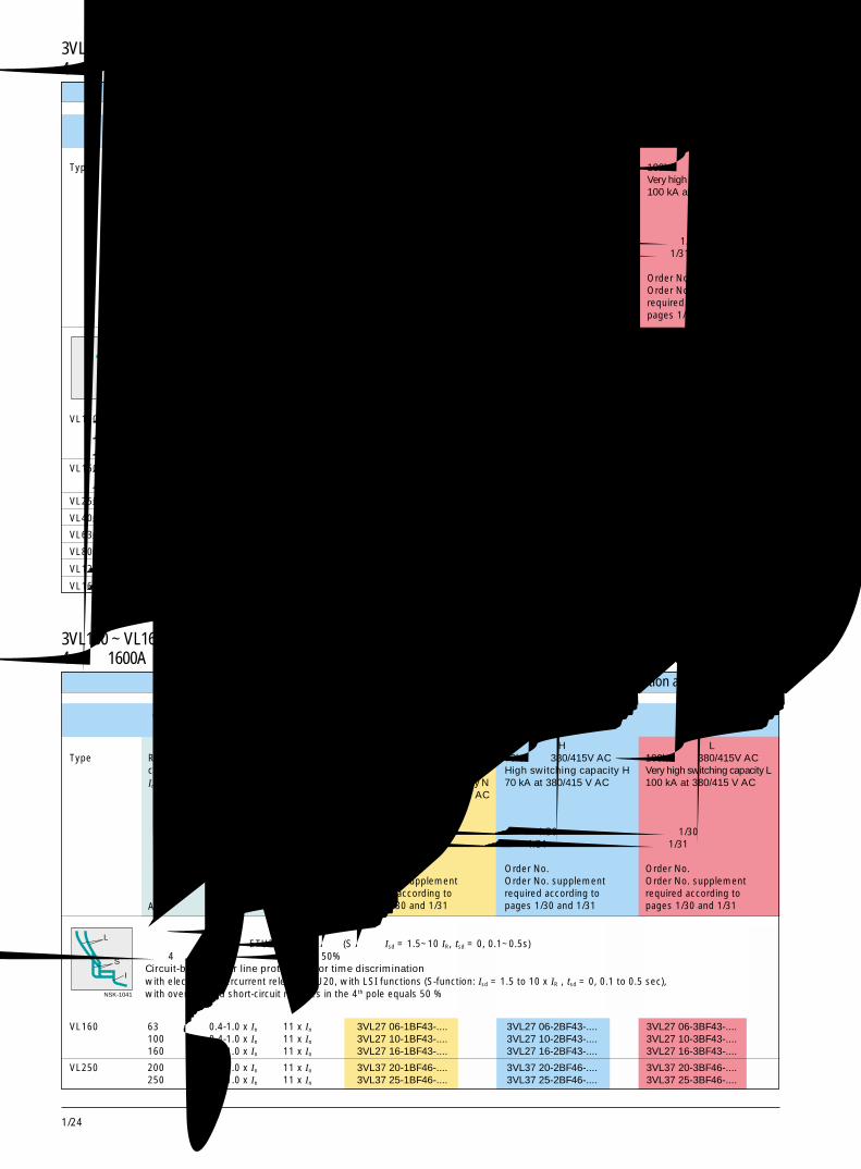
1/24
NSK-1040
L
S
I
NSK-1041
选型和订货数据 Selection and ordering data
4 极,1600A及以下 4-Pole, up to 1600A
固定安装式断路器 /Fixed-mounted circuit-breakers电磁式过电流脱扣器 /Magnetic overcurrent release
型号Type
额定电流RatedcurrentIn
A
过载反时限脱扣器“L”的整定电流Settingcurrent ofinverse-timedelayedoverloadrelease "L"IR
A
短路瞬时脱扣器“I”的整定电流Operatingcurrent ofcurrent ofinstantaneousshort-circuitrelease "I"Ii
A
标准分断能力 N40/45/50kA,在 380/415V AC 时见第 1/60 页Standard switching capacity N40/45/50 kA at 380/415 V ACsee page 1/60.订货号根据第 1/30 页和第 1/31 页所需的订货号后缀Order No.Order No. supplementrequired according topages 1/30 and 1/31
高分断能力 H70kA,在 380/415V AC 时High switching capacity H70 kA at 380/415 V AC
订货号根据第 1/30 页和第 1/31 页所需的订货号后缀Order No.Order No. supplementrequired according topages 1/30 and 1/31
带电磁式过电流脱扣器的隔离开关Non-automatic circuit-breakers with magnetic overcurrent release
3VL160 ~ VL1600 断路器 3VL160 to VL1600 Circuit-Breakers
选型和订货数据 Selection and ordering data
4 极,1600A及以下 4-Pole, up to 1600A
固定安装式断路器 /Fixed-mounted circuit-breakers电子式过电流脱扣器 /Electronic overcurrent release
型号Type
额定电流RatedcurrentIn
A
过载反时限脱扣器“L”的整定电流Settingcurrent ofinverse-timedelayedoverloadrelease "L"IR
A
短路瞬时脱扣器“I”的整定电流Operatingcurrent ofcurrent ofinstantaneousshort-circuitrelease "I"Ii
A
标准分断能力 N40/45/50kA,在 380/415V AC 时见第 1/60 页Standard switching capacity N40/45/50 kA at 380/415 V ACsee page 1/60.订货号根据第 30 页和第 31 页所需的订货号后缀Order No.Order No. supplementrequired according topages 1/30 and 1/31
高分断能力 H70kA,在 380/415V AC时High switching capacity H70 kA at 380/415 V AC
订货号根据第 1/30 页和第 1/31 页所需的订货号后缀Order No.Order No. supplementrequired according topages 1/30 and 1/31
线路保护用断路器,用于时间选择性带电子式过电流脱扣器 ETU20,带 LSI 功能 (S 功能:Isd = 1.5~10 IR, tsd = 0, 0.1~0.5s)在第 4 极中带过载和短路脱扣器,等于 50%Circuit-breakers for line protection, for time discriminationwith electronic overcurrent release ETU20, with LSI functions (S-function: Isd = 1.5 to 10 x IR , tsd = 0, 0.1 to 0.5 sec),with overload and short-circuit releases in the 4th pole equals 50 %
3VL160X ~ VL1600 断路器 3VL160X to VL1600 Circuit-Breakers
极高分断能力 L100kA,在 380/415V AC 时Very high switching capacity L100 kA at 380/415 V AC
订货号根据第 1/30 页和第 1/31 页所需的订货号后缀Order No.Order No. supplementrequired according topages 1/30 and 1/31
极高分断能力 L100kA,在 380/415V AC 时Very high switching capacity L100 kA at 380/415 V AC
订货号根据第 1/30 页和第 1/31 页所需的订货号后缀Order No.Order No. supplementrequired according topages 1/30 and 1/31
VL160X 至 /up to 100 - 2500 3VL17 10-1EE43-.... 3VL17 10-2EE43-.... -
至 /up to 125 - 3000 3VL17 12-1EE43-.... 3VL17 12-2EE43-....
至 /up to 160 - 3000 3VL17 16-1EE43-.... 3VL17 16-2EE43-....
VL160 至 /up to 100 - 2500 3VL27 10-1EE43-.... 3VL27 10-2EE43-.... 3VL27 10-3EE43-....
至 /up to 160 - 2500 3VL27 16-1EE43-.... 3VL27 16-2EE43-.... 3VL27 16-3EE43-....
VL250 至 /up to 250 - 4000 3VL37 25-1EE46-.... 3VL37 25-2EE46-.... 3VL37 25-3EE46-....
VL400 至 /up to 400 - 6000 3VL47 40-1EE46-.... 3VL47 40-2EE46-.... 3VL47 40-3EE46-....
VL630 至 /up to 630 - 6500 3VL57 63-1EE46-... 3VL57 63-2EE46-.... 3VL57 63-3EE46-....
VL800 至 /up to 800 - 8000 3VL67 80-1EE46-.... 3VL67 80-2EE46-.... 3VL67 80-3EE46-....
VL1250 至 /up to 1250 - 12000 3VL77 12-1EE46-.... 3VL77 12-2EE46-.... 3VL77 12-3EE46-....
VL1600 至 /up to 1600 - 16000 3VL87 16-1EE40-.... 3VL87 16-2EE40-.... 3VL87 16-3EE40-....
VL160 63 0.4-1.0 x In 11 x In 3VL27 06-1BF43-.... 3VL27 06-2BF43-.... 3VL27 06-3BF43-....100 0.4-1.0 x In 11 x In 3VL27 10-1BF43-.... 3VL27 10-2BF43-.... 3VL27 10-3BF43-....160 0.4-1.0 x In 11 x In 3VL27 16-1BF43-.... 3VL27 16-2BF43-.... 3VL27 16-3BF43-....
VL250 200 0.4-1.0 x In 11 x In 3VL37 20-1BF46-.... 3VL37 20-2BF46-.... 3VL37 20-3BF46-....250 0.4-1.0 x In 11 x In 3VL37 25-1BF46-.... 3VL37 25-2BF46-.... 3VL37 25-3BF46-....
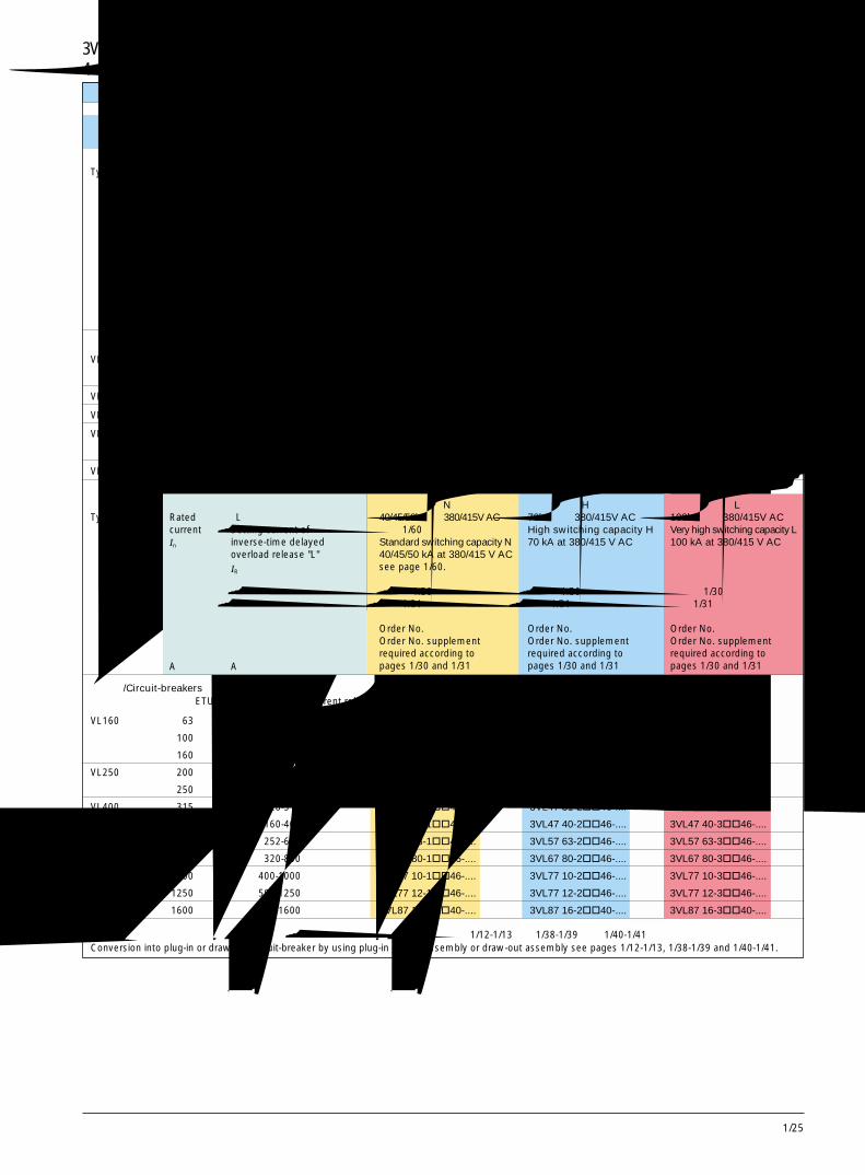
1/25
14 极,1600A 及以下 4-Pole, up to 1600A选型和订货数据 Selection and ordering data
固定安装式断路器 /Fixed-mounted circuit-breakers电子式过电流脱扣器 /Electronic overcurrent release
型号Type
额定电流RatedcurrentIn
A
过载反时限脱扣器“L”的整定电流Settingcurrent ofinverse-timedelayedoverloadrelease "L"IR
A
断路器 /Circuit-breakers带电子式过电流脱扣器 ETU /with electronic overcurrent release ETU
标准分断能力 N40/45/50kA,在 380/415V AC 时见第 1/60 页Standard switching capacity N40/45/50 kA at 380/415 V ACsee page 1/60.订货号根据第 1/30 页和第 1/31 页所需的订货号后缀Order No.Order No. supplementrequired according topages 1/30 and 1/31
高分断能力 H70kA,在 380/415V AC 时High switching capacity H70 kA at 380/415 V AC
订货号根据第 1/30 页和第 1/31 页所需的订货号后缀Order No.Order No. supplementrequired according topages 1/30 and 1/31
3VL160 ~ VL1600 断路器 3VL160 to VL1600 Circuit-Breakers
通过使用插入式插座组件或抽屉式组件可改装成插入式断路器或抽屉式断路器。见第 1/12-1/13 页、1/38-1/39 页和 1/40-1/41 页。Conversion into plug-in or draw-out circuit-breaker by using plug-in socket assembly or draw-out assembly see pages 1/12-1/13, 1/38-1/39 and 1/40-1/41.
极高分断能力 L100kA,在 380/415V AC 时Very high switching capacity L100 kA at 380/415 V AC
订货号根据第 1/30 页和第 1/31 页所需的订货号后缀Order No.Order No. supplementrequired according topages 1/30 and 1/31
VL400 315 0.4-1.0 x In 11 x In 3VL47 31-1BF46-.... 3VL47 31-2BF46-.... 3VL47 31-3BF46-....
400 0.4-1.0 x In 11 x In 3VL47 40-1BF46-.... 3VL47 40-2BF46-.... 3VL47 40-3BF46-....
VL630 630 0.4-1.0 x In 11 x In 3VL57 63-1BF46-.... 3VL57 63-2BF46-.... 3VL57 63-3BF46-....
VL800 800 0.4-1.0 x In 11 x In 3VL67 80-1BF46-.... 3VL67 80-2BF46-.... 3VL67 80-3BF46-....
VL1250 1000 0.4-1.0 x In 11 x In 3VL77 10-1BF46-.... 3VL77 10-2BF46-.... 3VL77 10-3BF46-....
1250 0.4-1.0 x In 11 x In 3VL77 12-1BF46-.... 3VL77 12-2BF46-.... 3VL77 12-3BF46-....
VL1600 1600 0.4-1.0 x In 11 x In 3VL87 16-1BF40-.... 3VL87 16-2BF40-.... 3VL87 16-3BF40-....
VL160 63 25-63 3VL27 06-1��43-.... 3VL27 06-2��43-.... 3VL27 06-3��43-....
100 40-100 3VL27 10-1��43-.... 3VL27 10-2��43-.... 3VL27 10-3��43-....
160 64-160 3VL27 16-1��43-.... 3VL27 16-2��43-.... 3VL27 16-3��43-....
VL250 200 80-200 3VL37 20-1��46-.... 3VL37 20-2��46-.... 3VL37 20-3��46-....
250 100-250 3VL37 25-1��46-.... 3VL37 25-2��46-.... 3VL37 25-3��46-....
VL400 315 128-315 3VL47 31-1��46-.... 3VL47 31-2��46-.... 3VL47 31-3��46-....
400 160-400 3VL47 40-1��46-.... 3VL47 40-2��46-.... 3VL47 40-3��46-....
VL630 630 252-630 3VL57 63-1��46-.... 3VL57 63-2��46-.... 3VL57 63-3��46-....
VL800 800 320-800 3VL67 80-1��46-.... 3VL67 80-2��46-.... 3VL67 80-3��46-....
VL1250 1000 400-1000 3VL77 10-1��46-.... 3VL77 10-2��46-.... 3VL77 10-3��46-....
1250 500-1250 3VL77 12-1��46-.... 3VL77 12-2��46-.... 3VL77 12-3��46-....
VL1600 1600 640-1600 3VL87 16-1��40-.... 3VL87 16-2��40-.... 3VL87 16-3��40-....
短路瞬时脱扣器“I”的整定电流Operatingcurrent ofcurrent ofinstantaneousshort-circuitrelease "I"Ii
型号Type
额定电流RatedcurrentIn
A
过载反时限脱扣器“L”的整定电流Setting current ofinverse-time delayedoverload release "L"IR
A
标准分断能力 N40/45/50kA,在 380/415V AC 时见第 1/60 页Standard switching capacity N40/45/50 kA at 380/415 V ACsee page 1/60.订货号根据第 1/30 页和第 1/31 页所需的订货号后缀Order No.Order No. supplementrequired according topages 1/30 and 1/31
高分断能力 H70kA,在 380/415V AC 时High switching capacity H70 kA at 380/415 V AC
订货号根据第 1/30 页和第 1/31 页所需的订货号后缀Order No.Order No. supplementrequired according topages 1/30 and 1/31
极高分断能力 L100kA,在 380/415V AC 时Very high switching capacity L100 kA at 380/415 V AC
订货号根据第 1/30 页和第 1/31 页所需的订货号后缀Order No.Order No. supplementrequired according topages 1/30 and 1/31

1/26
NSK-1188
L
S
I
NSK-1189
L
S
IG
NSK-1190
L
S
I
NSK-1444
L
S
IG
带 LIG 功能的线路保护,ETU12接地保护用于 3 相 4 线系统N 极无过电流保护 BC BC BCN 极有过电流保护 N=50% BD BD BDLine protection with LIG functions, ETU12residual earth for 3-phase 4-wire systemsN-pole not overcurrent protected BC BC BCN-pole overcurrent protected N=50% BD BD BD
带 LSI 功能的线路保护,ETU20N 极无过电流保护 BE BE BEN 极有过电流保护 N=50% BF BF BFLine protection with LSI functions, ETU20N-pole not overcurrent protected BE BE BEN-pole overcurrent protected N=50% BF BF BF
带 LSIG 功能的线路保护,ETU22接地保护用于 3 相 4 线系统N 极无过电流保护 BG BG BGN 极有过电流保护 N=50% BH BH BHLine protection with LSIG functions, ETU22residual earth for 3-phase 4-wire systemsN-pole not overcurrent protected BG BG BGN-pole overcurrent protected N=50% BH BH BH
4极断路器用脱扣器 LCD ETULCD ETU release 4-pole construction
带 LI/LS/LSI 功能的线路保护,ETU40N 极过电流设定在 50~100% 及无保护工厂装运默认整定在 50% CJ CJ CJLine protection with LI/LS/LSIfunctions, ETU40N-pole overcurrent may beset between 50~100% and offfactory shipping default setting at 50 % CJ CJ CJ
带 LSIG 功能的线路保护,ETU42用于 3 相 4 线系统N 极过电流设定在 50~100% 及无保护工厂装运默认整定在 50% CN CN CNLine protection with LSIGfunctions, ETU42for 3-phase 4-wire systemsN-pole overcurrent may beset between 50~100% and offfactory shipping default setting at 50 % CN CN CN
通过使用插入式插座组件或抽屉式组件可改装成插入式断路器或抽屉式断路器。见第 1/12-1/13 页、1/38-1/39 页和 1/40-1/41 页。Conversion into plug-in or draw-out circuit-breaker by using plug-in socket assembly or draw-out assembly see pages1/12-1/13, 1/38-1/39 and 1/40-1/41.
选型和订货数据 Selection and ordering data
4 极,1600A 及以下 4-Pole, up to 1600A
订货号后缀 订货号后缀 订货号后缀Order No. Order No. Order No.supplement supplement supplement
NSK-1028
L
IG
3VL160 ~ VL1600 断路器 3VL160 to VL1600 Circuit-Breakers
NSK-1026
L
I
4 极断路器用脱扣器 ETUETU release 4-pole construction
带 LI 功能的线路保护,ETU10N 极无过电流保护 BB BB BBN 极有过电流保护 N=50% BA BA BALIne protection with LI functions, ETU10N-pole not overcurrent protected BB BB BBN-pole overcurrent protected N=50% BA BA BA
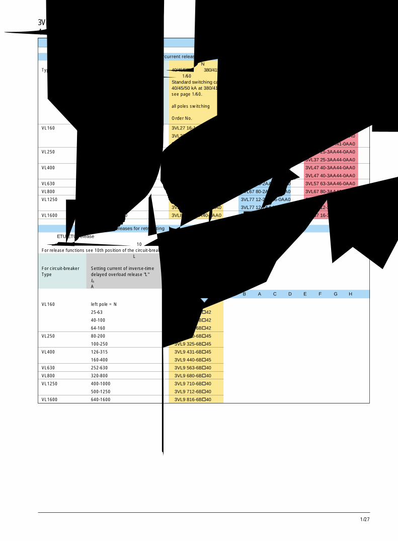
1/27
14 极,1600A 及以下 4-Pole, up to 1600A选型和订货数据 Selection and ordering data
不带过电流脱扣器的断路器 /Circuit-breakers without overcurrent release
型号Type
额定电流Rated current
In
A
标准分断能力 N40/45/50kA,在 380/415V AC 时见第 1/60 页Standard switching capacity N40/45/50 kA at 380/415 V ACsee page 1/60.所有极断开all poles switching订货号Order No.
高分断能力 H70kA,在 380/415V AC 时High switching capacity H70 kA at 380/415 V AC
所有极断开all poles switching订货号Order No.
极高分断能力 L100kA,在 380/415V AC 时Very high switching capacity L100 kA at 380/415 V AC
所有极断开all poles switching订货号Order No.
VL160 25-63 3VL27 16-1AA41-0AA0 3VL27 16-2AA41-0AA0 3VL27 16-3AA41-0AA0
40-100 3VL27 16-1AA41-0AA0 3VL27 16-2AA41-0AA0 3VL27 16-3AA41-0AA0
64-160 3VL27 16-1AA41-0AA0 3VL27 16-2AA41-0AA0 3VL27 16-3AA41-0AA0
VL250 80-200 3VL37 25-1AA44-0AA0 3VL37 25-2AA44-0AA0 3VL37 25-3AA44-0AA0
100-250 3VL37 25-1AA44-0AA0 3VL37 25-2AA44-0AA0 3VL37 25-3AA44-0AA0
VL400 126-315 3VL47 40-1AA44-0AA0 3VL47 40-2AA44-0AA0 3VL47 40-3AA44-0AA0
160-400 3VL47 40-1AA44-0AA0 3VL47 40-2AA44-0AA0 3VL47 40-3AA44-0AA0
VL630 252-630 3VL57 63-1AA46-0AA0 3VL57 63-2AA46-0AA0 3VL57 63-3AA46-0AA0
VL800 320-800 3VL67 80-1AA46-0AA0 3VL67 80-2AA46-0AA0 3VL67 80-3AA46-0AA0
VL1250 400-1000 3VL77 12-1AA46-0AA0 3VL77 12-2AA46-0AA0 3VL77 12-3AA46-0AA0
500-1250 3VL77 12-1AA46-0AA0 3VL77 12-2AA46-0AA0 3VL77 12-3AA46-0AA0
VL1600 640-1600 3VL87 16-1AA40-0AA0 3VL87 16-2AA40-0AA0 3VL87 16-3AA40-0AA0
改装用过电流脱扣器 /Overcurrent releases for retrofitting
脱扣器 ETU/ETU release
有关脱扣器功能,参见上页断路器订货号的第 10 个位置。For release functions see 10th position of the circuit-breaker Order No. on previous page.用于断路器型号 过载反时限脱扣器“L”的整定电流 订货号
For circuit-breaker Setting current of inverse-time Order No.Type delayed overload release "L"
IR
A
VL160 left pole = N
25-63 3VL9 206-6B�42
40-100 3VL9 210-6B�42
64-160 3VL9 216-6B�42
VL250 80-200 3VL9 320-6B�45
100-250 3VL9 325-6B�45
VL400 126-315 3VL9 431-6B�45
160-400 3VL9 440-6B�45
VL630 252-630 3VL9 563-6B�40
VL800 320-800 3VL9 680-6B�40
VL1250 400-1000 3VL9 710-6B�40
500-1250 3VL9 712-6B�40
VL1600 640-1600 3VL9 816-6B�40
功能function
B A C D E F G H
3VL160 ~ VL1600 断路器 3VL160 to VL1600 Circuit-Breakers
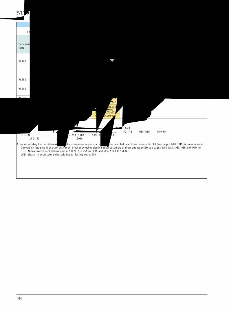
1/28
脱扣器 LCD ETU/LCD ETU release
用于断路器型号 过载反时限脱扣器“L” 订货号的整定电流
For circuit-breaker Setting current of inverse-time Order No.Type delayed overload release "L" IR
A
VL160 left pole = N
25-63 3VL9 206-6C�42
40-100 3VL9 210-6C�42
64-160 3VL9 216-6C�42
VL250 80-200 3VL9 320-6C�45
100-250 3VL9 325-6C�45
VL400 126-315 3VL9 431-6C�45
160-400 3VL9 440-6C�45
VL630 252-630 3VL9 563-6C�40
VL800 320-800 3VL9 680-6C�40
VL1250 400-1000 3VL9 710-6C�40
500-1250 3VL9 712-6C�40
VL1600 640-1600 3VL9 816-6C�40
功能function
J N
在组装了带过电流脱扣器的断路器之后,应使用手持电子式脱扣器测试元件 (见第 1/48 页,1/49 页) 进行测试。通过使用插入式插座组件或抽屉式组件可改装成插入式断路器或抽屉式断路器。见第 1/12-1/13 页、1/38-1/39 页和 1/40-1/41 页。ETU - N 极过电流脱扣器整定在 100% IR = 25A~100A 以及 50% 110A~1600A脱扣器 LCD - N 保护可选择有 / 无 - 工厂整定在 50%
After assembling the circuit-breaker with the overcurrent release, a test with the hand held electronic release test kit (see pages 1/48, 1/49) is recommended.Conversion into plug-in or draw-out circuit- breaker by using plug-in socket assembly or draw-out assembly see pages 1/12-1/13, 1/38-1/39 and 1/40-1/41.ETU - N-pole overcurrent releases set at 100 % IR = 25A to 100A and 50% 110A to 1600ALCD release - N-protection selectable in/out - factory set at 50%
4 极,1600A 及以下 4-Pole, up to 1600A选型和订货数据 Selection and ordering data
3VL160 ~ VL1600 断路器 3VL160 to VL1600 Circuit-Breakers
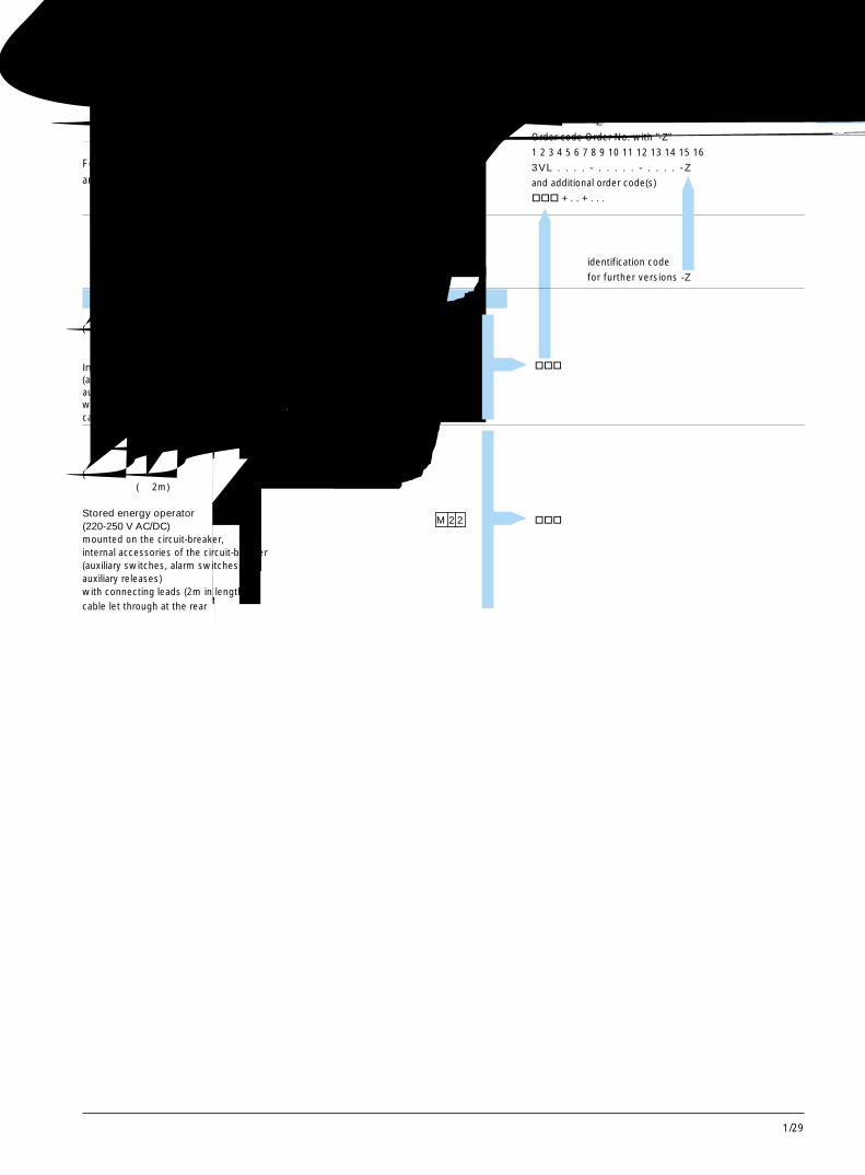
1/29
13极和 4 极,1600A 及以下 3- and 4-Pole, up to 1600A其他类型 Further versions
订货时,将“-Z”增加到完整的订货号中
并注明相应的订货代码。
For ordering, add "-Z" to the complete Order No.
and indicate the appropriate order code(s).
订货代码 订货号,带“-Z”
Order code Order No. with "-Z"
1 2 3 4 5 6 7 8 9 10 11 12 13 14 15 16
3VL . . . . - . . . . . - . . . . -Z
and additional order code(s)
��� + . . + . . .
和附加订货代码
identification code
for further versions -Z
用于固定安装式断路器 /For fixed-mounted circuit-breakers
内部附件 VL160X, VL160, VL250, VL400(辅助开关,报警开关,辅助脱扣器) VL630, VL800, VL1250, VL1600带连接引线 (长 2m)电缆在背面通过Internal accessories(auxiliary switches, alarm switches,auxiliary releases)with connecting leads (2m in length)cable let through at the rear
储能操作机构 (220-250V AC/DC) VL160X, VL160, VL250安装在断路器上, VL400, VL630断路器的内部附件 VL800(辅助开关,报警开关,辅助脱扣器) VL1250, VL1600带连接引线 (长 2m)电缆在背面通过Stored energy operator(220-250 V AC/DC)mounted on the circuit-breaker,internal accessories of the circuit-breaker(auxiliary switches, alarm switches,auxiliary releases)with connecting leads (2m in length)cable let through at the rear
L 0 2 ���
M 2 2 ���
3VL160X ~ VL1600 断路器 3VL160X to VL1600 Circuit-Breakers
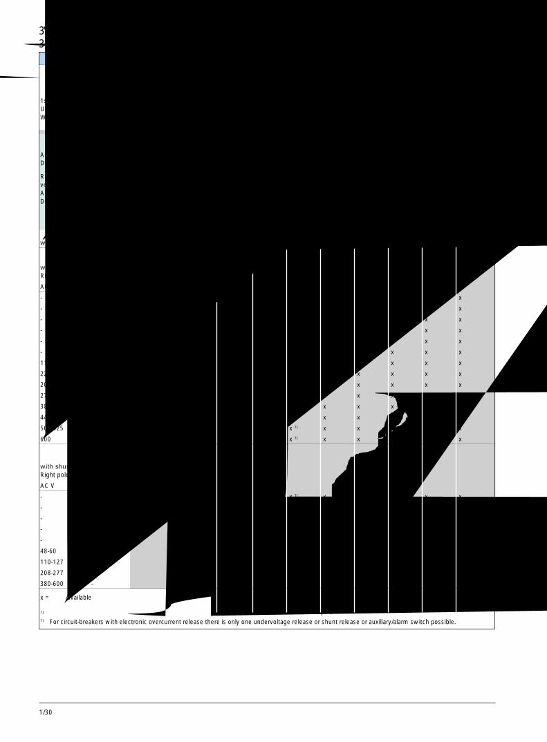
1/30
3 极和 4 极,1600A 及以下 3- and 4-Pole, up to 1600A订货号后缀 Order No. supplements
第 1 个订货号后缀欠压脱扣器或分励脱扣器导线直接接到附件上1st Order No. supplementUndervoltage release or shunt releaseWiring to be made directly to accessory
x = 可用 /available
1) 对于带电子式过电流脱扣器的断路器来说,仅可有一个欠压脱扣器或一个分励脱扣器或一个辅助 / 报警开关。1) For circuit-breakers with electronic overcurrent release there is only one undervoltage release or shunt release or auxiliary/alarm switch possible.
额定控制 订货号后缀 断路器电压 Us/ 频率AC 50/60Hz 型号DC
Rated control supply Order No. supplement Circuit-breakersvoltage Us /frequency TypeAC 50/60 HzDC
3VL . . . . - . . . . . -��. . VL160X VL160 VL250 VL400 VL630 VL800 VL1250 VL1600
不带辅助脱扣器 0 A 无 无 无 无 无 无 无 无without auxiliary release none none none none none none none none带欠压脱扣器仅限右极with undervoltage releaseRight pole only
AC V DC V
- 12 2N x x 1)) x 1) x x x x x
- 24 2 P x x 1) x1) x x x x x
- 48 2U x x 1) x1) x x x x x
- 60 2 V x x 1) x1) x x x x x
- 110-127 2 R x x 1) x 1) x x x x x
- 220-250 2 S x x 1) x 1) x x x x x
110-127 - 2G x x1) x 1) x x x x x
220-250 - 2 H x x 1) x 1) x x x x x
208 - 2M x x 1) x 1) x x x x x
277 - 2Q x x 1) x 1) x x x x x
380-415 - 2 J x x 1) x 1) x x x x x
440-480 - 2 K x x 1) x 1) x x x x x
500-525 - 2 L x x 1) x 1) x x x x x
600 - 2 T x x 1) x 1) x x x x x
带分励脱扣器仅限右极with shunt releaseRight pole only
AC V DC V
- 12 8 B x x 1) x 1) x x x x x
- 24 8 C x x 1) x 1) x x x x x
- 48-60 8 J x x 1) x 1) x x x x x
- 110-127 8 K x x 1) x 1) x x x x x
- 220-250 8Q x x 1) x 1) x x x x x
48-60 - 8M x x 1) x 1) x x x x x
110-127 - 8 R x x 1) x 1) x x x x x
208-277 - 8 T x x 1) x 1) x x x x x
380-600 - 8 V x x 1) x 1) x x x x x
3VL160X ~ VL1600 断路器 3VL160X to VL1600 Circuit-Breakers
1/31
3VL160X~VL1600断路器 3VL160X to VL1600 Circuit-Breakers3 极和 4 极,16 到 1600A 3- and 4-Pole, 16 to 1600A 1订货号后缀 Order No. supplements
3SB安装托架 /3SB-adapter
适合的断路器 辅助开关 (HS) 和报警开 用于安装到断路器 用于安装到断路 用于安装到断路For circuit-breaker 关 (AS) 的最大组合 的N极中 器的左极中 器的右极中
Maximum combination For mounting into For mounting into For mounting intoof auxiliary switches (HS) the N-Pole of the the left pole of the the right pole of theand alarm switches (AS) circuit-breaker circuit-breaker circuit-breaker
型号 组 (见第 1/14/1/15 页) 订货号 订货号 订货号Type Group (see page 1/14/1/15) Order No. Order No.Order No.
VL160X 1 至 /up to 3 HS 2 ) - 3VL9 400-2AH00 3VL9 400-2AH00VL160VL250 2HS + 1 AS 2 ) - 3VL9 400-2AJ10 3VL9 400-2AJ20VL400VL630 2 至 /up to 4 HS - 3VL9 816-2AL00 3VL9 816-2AL00VL800,VL1250, 2 HS + 2 AS - 3VL9 816-2AN10 -VL1600
1HS或 1AS,带常开触头 3SB34 00-0J
1 HS or 1 AS with NO contact 3SB34 00-0J
1HS或 1AS,带常闭触头 3SB34 00-0K
1 HS or 1 AS with NC contact 3SB34 00-0K
附件 Accessories
当用户想要获得在标准配件供货中未包括的辅助开关或报警开关或开关触头
配置时,上表中标明的3SB安装托架可按期望的开关和触头配置单独订购:
When a customer desires auxiliary switch or alarm switch or switch
contact configurations not included in the standard kit offerings,
the 3SB-adapter indicated in the table above may be ordered along
with the desired switches and contact configurations as separate
items:
1) 仅使用该配件中的一个开关(该配件由 1 个常闭触头和 1 个常开触头组成)。
1) Use only one switch from this kit (kit consists of 1 NC and 1 NO contact switches).
2) 不包括安装到带 RCD模块的 3VL160X 断路器的左极内以及安装到带电子式过电流脱扣器的 3VL160, VL250 断路器的左极内。
仅针对该应用,可在 N 极 (仅限 4 极断路器) 中安装。
2) Except for mounting into the left pole for 3VL160X circuit-breaker with RCD module and 3VL160, VL250 circuit-breakerswith electronic
overcurrent release.
Bracket may be installed in N-pole (4-pole circuit-breaker only) for this application only.
第 2个订货号后缀2nd Order No. supplement辅助开关(HS)和报警开关(AS)Auxiliary switches (HS) and alarm switches (AS)左 /右极Left/right pole直接接导线到附件上Wiring to be made directly to accessory
补充 订货号后缀 断路器Complement Order No. supplement Circuit-breakers
型号 /Type
HS = 1 个触点开关 3VL . . . . - . . . . . -. .�� VL160X VL160 VL250 VL400 VL630 VL800 VL1250 VL1600HS = 1 contact switchAS = 1 个触点开关AS = 1 contact switch
不带辅助 / 报警开关 无 无 无 无 无 无 无 无without auxiliary/alarm switch A 0 none none none none none none none none2 HS (1 NO/1 NC) B 1 x x x x - - - -4 HS (2 NO/2 NC) C 1 - - - - x x x x1 AS (1 NO) G 11) x x x x - - - -2 HS (1 NO/1 NC) + 1 AS (1 NO) D 1 x x x x - - - -2 HS (1 NO/1 NC) + 1 AS (1 NO) E 1 - - - - x x x x
x = 可用 / available- = 不可用 /not available
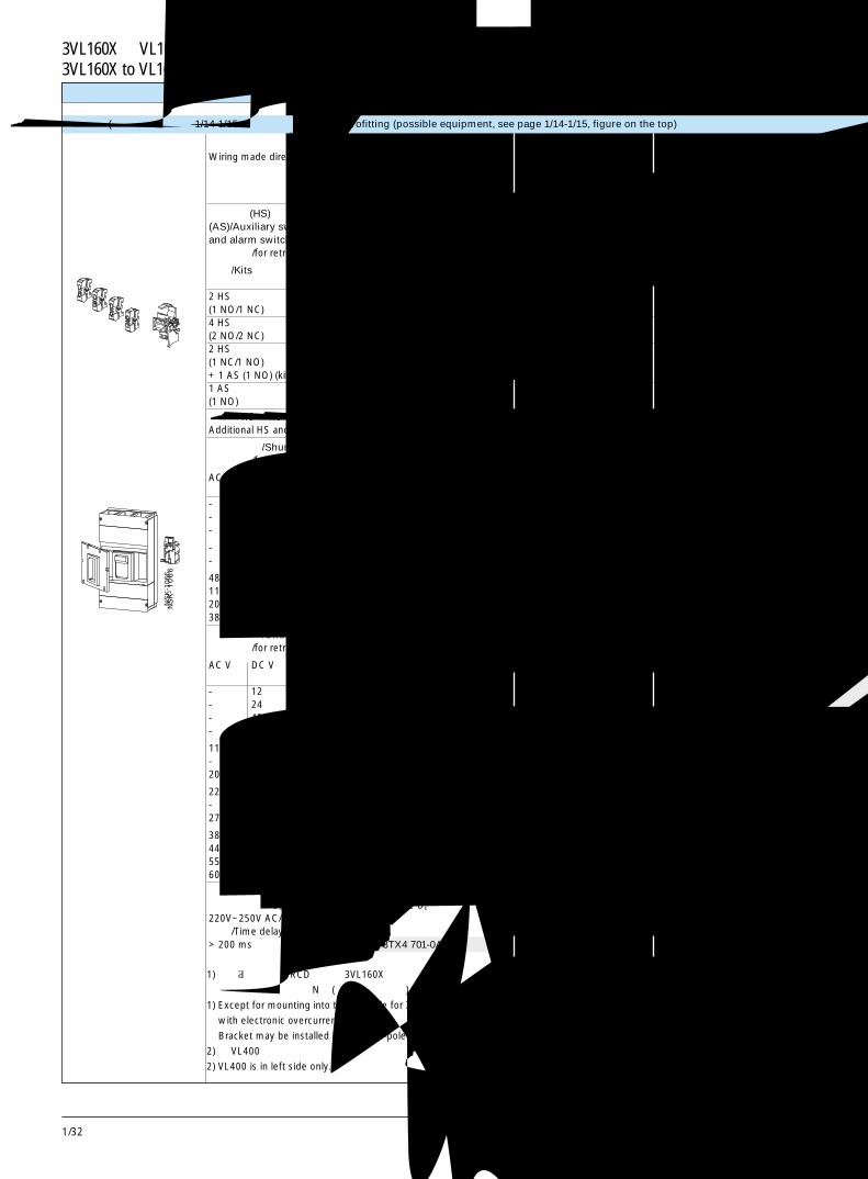
1/32
3VL160X ~VL1600断路器3VL160X to VL1600 Circuit-Breakers
NS
K-1
066
附件
1) 不包括安装到带RCD模块的 3VL160X断路器的左极内以及安装到带电子式过电流脱扣器的 3VL160, VL250断路器的左极内。
仅针对该应用,可在 N 极(仅限 4 极断路器)中安装。
1) Except for mounting into the left pole for 3VL160X circuit-breaker with RCD module and 3VL160, VL250 circuit-breakers
with electronic overcurrent release.
Bracket may be installed in N-pole (4-pole circuit-breaker only) for this application only.
2) 对 VL400 只能在左侧。
2) VL400 is in left side only.
用于改装(其安装说明,见第 1/14-1/15页,上部的示图) /For retrofitting (possible equipment, see page 1/14-1/15, figure on the top)
直接接导线到附件上 用于 /For VL160X 用于 /For VL160 用于 /For VL250Wiring made directly to accessory
订货号 订货号 订货号Order No. Order No. Order No.3 极和 4 极 /3- or 4-pole
辅助开关(HS)和报警开关(AS)/Auxiliary switches (HS)and alarm switches (AS)用于改装 /for retrofitting
配件 /Kits 安装位置Mounting side
2 HS N, 左 1), 右 3VL9 400-2AB00 3VL9 400-2AB00 3VL9 400-2AB00(1 NO/1 NC) N, Left 1 ), Right4 HS N, 左, 右 - - -(2 NO/2 NC) N, Left, Right2 HS 左, 右 2 ) 3VL9 400-2AD00 3VL9 400-2AD00 3VL9 400-2AD00(1 NC/1 NO) Left, Right 2 )
+ 1 AS (1 NO) (kit)1 AS 左, 右 1) 3VL9 400-2AG00 3VL9 400-2AG00 3VL9 400-2AG00(1 NO) Left, Right 1 )
附加的 HS 和 AS 第 1 组见第 1/14-1/15 页和 1/31 页。Additional HS and AS Group 1 see pages 1/14-1/15 and 1/31.
分励脱扣器 /Shunt releases用于改装 /for retrofitting
AC V DC V 仅为右极Right pole only
- 12 Right pole only 3VL9 400-1SB00 3VL9 400-1SB00 3VL9 400-1SB00- 24 Right pole only 3VL9 400-1SC00 3VL9 400-1SC00 3VL9 400-1SC00- 48-60 Right pole only 3VL9 400-1SJ00 3VL9 400-1SJ00 3VL9 400-1SJ00
- 110-127 Right pole only 3VL9 400-1SK00 3VL9 400-1SK00 3VL9 400-1SK00- 220-250 Right pole only 3VL9 400-1SQ00 3VL9 400-1SQ00 3VL9 400-1SQ00
48-60 - Right pole only 3VL9 400-1SM00 3VL9 400-1SM00 3VL9 400-1SM00110-127 - Right pole only 3VL9 400-1SR00 3VL9 400-1SR00 3VL9 400-1SR00208-277 - Right pole only 3VL9 400-1ST00 3VL9 400-1ST00 3VL9 400-1ST00380-600 - Right pole only 3VL9 400-1SV00 3VL9 400-1SV00 3VL9 400-1SV00
欠压脱扣器 /Undervoltage releases用于改装 /for retrofitting
AC V DC V 仅为右极Right pole only
- 12 Right pole only 3VL9 400-1UN00 3VL9 400-1UN00 3VL9 400-1UN00- 24 Right pole only 3VL9 400-1UP00 3VL9 400-1UP00 3VL9 400-1UP00- 48 Right pole only 3VL9 400-1UU00 3VL9 400-1UU00 3VL9 400-1UU00- 60 Right pole only 3VL9 400-1UV00 3VL9 400-1UV00 3VL9 400-1UV00
110-127 - Right pole only 3VL9 400-1UG00 3VL9 400-1UG00 3VL9 400-1UG00- 110-127 Right pole only 3VL9 400-1UR00 3VL9 400-1UR00 3VL9 400-1UR00208 - Right pole only 3VL9 400-1UM00 3VL9 400-1UM00 3VL9 400-1UM00
220-250 - Right pole only 3VL9 400-1UH00 3VL9 400-1UH00 3VL9 400-1UH00- 220-250 Right pole only 3VL9 400-1US00 3VL9 400-1US00 3VL9 400-1US00277 - Right pole only 3VL9 400-1UQ00 3VL9 400-1UQ00 3VL9 400-1UQ00
380-415 - Right pole only 3VL9 400-1UJ00 3VL9 400-1UJ00 3VL9 400-1UJ00440-480 - Right pole only 3VL9 400-1UK00 3VL9 400-1UK00 3VL9 400-1UK00550-525 - Right pole only 3VL9 400-1UL00 3VL9 400-1UL00 3VL9 400-1UL00600 - Right pole only 3VL9 400-1UT00 3VL9 400-1UT00 3VL9 400-1UT00
欠压脱扣器用延时装置 /Time-delay device for undervoltage releases额定控制电压 Us/Rated control supply voltage Us
220V~250V AC/DC延时 /Time delay> 200 ms 3TX4 701-0AN1 3TX4 701-0AN1 3TX4 701-0AN1
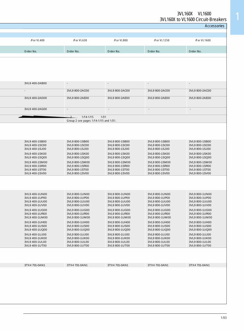
1/33
3VL160X~VL1600断路器3VL160X to VL1600 Circuit-Breakers 1
Accessories
用于 /For VL400 用于 /For VL630 用于 /For VL800 用于 /For VL1250 用于 /For VL1600
订货号 订货号 订货号 订货号 订货号Order No. Order No. Order No. Order No. Order No.
3VL9 400-2AB00 - - - -
- 3VL9 800-2AC00 3VL9 800-2AC00 3VL9 800-2AC00 3VL9 800-2AC00
3VL9 400-2AD00 3VL9 800-2AE00 3VL9 800-2AE00 3VL9 800-2AE00 3VL9 800-2AE00
3VL9 400-2AG00 - - - -
第 2 组见第 1/14-1/15 页和 1/31 页。Group 2 see pages 1/14-1/15 and 1/31.
3VL9 400-1SB00 3VL9 800-1SB00 3VL9 800-1SB00 3VL9 800-1SB00 3VL9 800-1SB003VL9 400-1SC00 3VL9 800-1SC00 3VL9 800-1SC00 3VL9 800-1SC00 3VL9 800-1SC003VL9 400-1SJ00 3VL9 800-1SJ00 3VL9 800-1SJ00 3VL9 800-1SJ00 3VL9 800-1SJ00
3VL9 400-1SK00 3VL9 800-1SK00 3VL9 800-1SK00 3VL9 800-1SK00 3VL9 800-1SK003VL9 400-1SQ00 3VL9 800-1SQ00 3VL9 800-1SQ00 3VL9 800-1SQ00 3VL9 800-1SQ00
3VL9 400-1SM00 3VL9 800-1SM00 3VL9 800-1SM00 3VL9 800-1SM00 3VL9 800-1SM003VL9 400-1SR00 3VL9 800-1SR00 3VL9 800-1SR00 3VL9 800-1SR00 3VL9 800-1SR003VL9 400-1ST00 3VL9 800-1ST00 3VL9 800-1ST00 3VL9 800-1ST00 3VL9 800-1ST003VL9 400-1SV00 3VL9 800-1SV00 3VL9 800-1SV00 3VL9 800-1SV00 3VL9 800-1SV00
3VL9 400-1UN00 3VL9 800-1UN00 3VL9 800-1UN00 3VL9 800-1UN00 3VL9 800-1UN003VL9 400-1UP00 3VL9 800-1UP00 3VL9 800-1UP00 3VL9 800-1UP00 3VL9 800-1UP003VL9 400-1UU00 3VL9 800-1UU00 3VL9 800-1UU00 3VL9 800-1UU00 3VL9 800-1UU003VL9 400-1UV00 3VL9 800-1UV00 3VL9 800-1UV00 3VL9 800-1UV00 3VL9 800-1UV00
3VL9 400-1UG00 3VL9 800-1UG00 3VL9 800-1UG00 3VL9 800-1UG00 3VL9 800-1UG003VL9 400-1UR00 3VL9 800-1UR00 3VL9 800-1UR00 3VL9 800-1UR00 3VL9 800-1UR003VL9 400-1UM00 3VL9 800-1UM00 3VL9 800-1UM00 3VL9 800-1UM00 3VL9 800-1UM00
3VL9 400-1UH00 3VL9 800-1UH00 3VL9 800-1UH00 3VL9 800-1UH00 3VL9 800-1UH003VL9 400-1US00 3VL9 800-1US00 3VL9 800-1US00 3VL9 800-1US00 3VL9 800-1US003VL9 400-1UQ00 3VL9 800-1UQ00 3VL9 800-1UQ00 3VL9 800-1UQ00 3VL9 800-1UQ00
3VL9 400-1UJ00 3VL9 800-1UJ00 3VL9 800-1UJ00 3VL9 800-1UJ00 3VL9 800-1UJ003VL9 400-1UK00 3VL9 800-1UK00 3VL9 800-1UK00 3VL9 800-1UK00 3VL9 800-1UK003VL9 400-1UL00 3VL9 800-1UL00 3VL9 800-1UL00 3VL9 800-1UL00 3VL9 800-1UL003VL9 400-1UT00 3VL9 800-1UT00 3VL9 800-1UT00 3VL9 800-1UT00 3VL9 800-1UT00
3TX4 701-0AN1 3TX4 701-0AN1 3TX4 701-0AN1 3TX4 701-0AN1 3TX4 701-0AN1
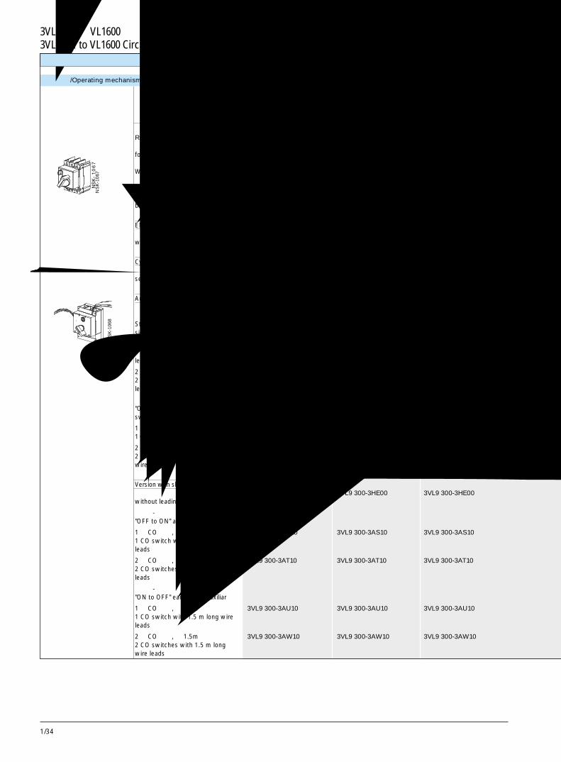
1/34
3VL160X ~VL1600断路器3VL160X to VL1600 Circuit-Breakers
操作机构 /Operating mechanisms
NS
K-1
067
NS
K-1
068
附件
用于 /For VL160X 用于 /For VL160 用于 /For VL250订货号 订货号 订货号Order No. Order No. Order No.3 极或 4 极 /3- or 4-pole
直接旋转驱动机构Rotary direct drive用于直接安装到断路器上。for direct fitting to the circuit-breaker.不带超前动作辅助开关。Without leading auxiliary switch.防护等级 IP 301), 黑色,Degree of protection IP 301),可用最多 3 个挂锁锁定。 3VL9 300-3HA00 3VL9 300-3HA00 3VL9 300-3HA00black, lockable with max. 3 padlocks
急停型EMERGENCY-STOP version带红色旋钮, 黄色显示牌 3VL9 300-3HC00 3VL9 300-3HC00 3VL9 300-3HC00with red knob, yellow indicator plate
现场安装用柱形锁Cylinder locks for field installation见第 1/48 页和 1/49 页。see pages 1/48 and 1/49.
附加的辅助开关配件Additional auxiliary switch kits标准型或急停型“分闸 - 合闸”辅助开关配件Standard or EMERGENCY-STOP ver-sion "OFF to ON" auxiliary switch kit
1 个 CO 开关, 带 1.5m 长的导线 3VL9 300-3AS10 3VL9 300-3AS10 3VL9 300-3AS101 CO switch with 1.5 m long wireleads
2 个 CO 开关, 带 1.5m 长的导线 3VL9 300-3AT10 3VL9 300-3AT10 3VL9 300-3AT102 CO switches with 1.5 m long wireleads
“合闸 - 分闸”先断辅助开关配件"ON to OFF" early break auxiliaryswitch kit
1 个 CO 开关, 带 1.5m 长的导线 3VL9 300-3AU10 3VL9 300-3AU10 3VL9 300-3AU101 CO switch with 1.5 m long wire leads
2 个 CO 开关, 带 1.5m 长的导线 3VL9 300-3AW10 3VL9 300-3AW10 3VL9 300-3AW102 CO switches with 1.5 m longwire leads
带轴管接头不带旋钮型 2)
Version with shaft stub without knob2)
不带超前动作辅助开关 3VL9 300-3HE00 3VL9 300-3HE00 3VL9 300-3HE00without leading auxiliary switch
“分闸 - 合闸”辅助开关配件"OFF to ON" auxiliary switch kit
1 个 CO 开关, 带 1.5m 长的导线 3VL9 300-3AS10 3VL9 300-3AS10 3VL9 300-3AS101 CO switch with 1.5 m long wireleads
2 个 CO 开关, 带 1.5m 长的导线 3VL9 300-3AT10 3VL9 300-3AT10 3VL9 300-3AT102 CO switches with 1.5 m long wireleads
“合闸 - 分闸”先断辅助开关配件"ON to OFF" early break auxiliar
1 个 CO 开关, 带 1.5m 长的导线 3VL9 300-3AU10 3VL9 300-3AU10 3VL9 300-3AU101 CO switch with 1.5 m long wireleads
2 个 CO 开关, 带 1.5m 长的导线 3VL9 300-3AW10 3VL9 300-3AW10 3VL9 300-3AW102 CO switches with 1.5 m longwire leads
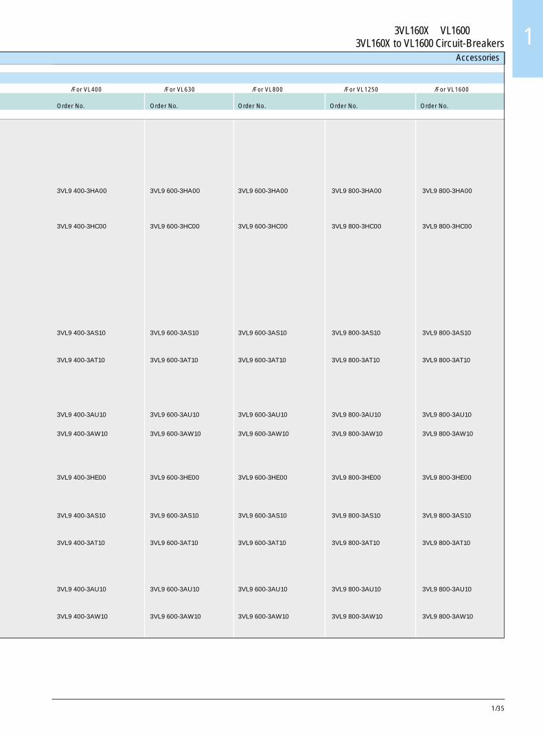
1/35
3VL160X~VL1600断路器3VL160X to VL1600 Circuit-Breakers 1
Accessories
用于 /For VL400 用于 /For VL630 用于 /For VL800 用于 /For VL1250 用于 /For VL1600订货号 订货号 订货号 订货号 订货号Order No. Order No. Order No. Order No. Order No.
3VL9 400-3HA00 3VL9 600-3HA00 3VL9 600-3HA00 3VL9 800-3HA00 3VL9 800-3HA00
3VL9 400-3HC00 3VL9 600-3HC00 3VL9 600-3HC00 3VL9 800-3HC00 3VL9 800-3HC00
3VL9 400-3AS10 3VL9 600-3AS10 3VL9 600-3AS10 3VL9 800-3AS10 3VL9 800-3AS10
3VL9 400-3AT10 3VL9 600-3AT10 3VL9 600-3AT10 3VL9 800-3AT10 3VL9 800-3AT10
3VL9 400-3AU10 3VL9 600-3AU10 3VL9 600-3AU10 3VL9 800-3AU10 3VL9 800-3AU10
3VL9 400-3AW10 3VL9 600-3AW10 3VL9 600-3AW10 3VL9 800-3AW10 3VL9 800-3AW10
3VL9 400-3HE00 3VL9 600-3HE00 3VL9 600-3HE00 3VL9 800-3HE00 3VL9 800-3HE00
3VL9 400-3AS10 3VL9 600-3AS10 3VL9 600-3AS10 3VL9 800-3AS10 3VL9 800-3AS10
3VL9 400-3AT10 3VL9 600-3AT10 3VL9 600-3AT10 3VL9 800-3AT10 3VL9 800-3AT10
3VL9 400-3AU10 3VL9 600-3AU10 3VL9 600-3AU10 3VL9 800-3AU10 3VL9 800-3AU10
3VL9 400-3AW10 3VL9 600-3AW10 3VL9 600-3AW10 3VL9 800-3AW10 3VL9 800-3AW10
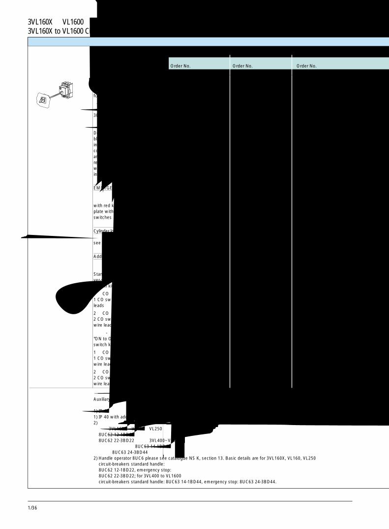
1/36
3VL160X ~VL1600断路器3VL160X to VL1600 Circuit-Breakers
加长旋转驱动机构,用于安装在门上和盖上Rotary drive extended, completefor fitting in doors and covers
防护等级 IP 65,包括带防护罩的黑色旋钮,显示牌,可拆卸式门偶合,300mm 加长轴,以及相关断路器用正面旋转驱动机构,可用最多 3 个挂锁锁定,带门联锁。 3VL9 300-3HF00 3VL9 300-3HF00 3VL9 300-3HF00Degree of protection IP 65, incl.black knob with masking frame,indicator plate, detachable doorcoupling, 300 mm extension shaft,and front rotary drive for therelevant circuit-breaker, lockablewith max. 3 padlocks, with doorinterlocking
急停型EMERGENCY-STOP version带红色旋钮, 黄色显示牌不带超前动作辅助开关 3VL9 300-3HG00 3VL9 300-3HG00 3VL9 300-3HG00with red knob, yellow indicatorplate without leading auxiliaryswitches
现场安装用柱形锁Cylinder locks for field installation见第 1/48 页和 1/49 页。see pages 1/48 and 1/49.
附加的辅助开关配件Additional auxiliary switch kits标准型或急停型“分闸 - 合闸”辅助开关配件Standard or EMERGENCY-STOPver-sion "OFF to ON" auxiliaryswitch kit
1 个 CO 开关, 带 1.5m 长的导线 3VL9 300-3AS10 3VL9 300-3AS10 3VL9 300-3AS101 CO switch with 1.5 m long wireleads
2 个 CO 开关, 带 1.5m 长的导线 3VL9 300-3AT10 3VL9 300-3AT10 3VL9 300-3AT102 CO switches with 1.5 m longwire leads
“合闸 - 分闸”先断辅助开关配件"ON to OFF" early break auxiliaryswitch kit
1 个 CO 开关, 带 1.5m 长的导线 3VL9 300-3AU10 3VL9 300-3AU10 3VL9 300-3AU101 CO switch with 1.5 m longwire leads
2 个 CO 开关, 带 1.5m 长的导线 3VL9 300-3AW10 3VL9 300-3AW10 3VL9 300-3AW102 CO switches with 1.5 m longwire leads
辅助开关 CO (转换开关) = 一组 1 常开触头 /1 常闭触头Auxiliary switch CO (changeover switch) = 1 NO/1 NC set of contacts.
1) IP 40,附加面框安装在门开孔上。1) IP 40 with additional cover frame mounted on door cutout.2) 有关手柄操作机构 8UC6,请见产品目录 NS K,第 13 节。
有关 3VL160X,VL160,VL250 断路器标准手柄的基本详情如下:8UC62 12-1BD22, 急停:8UC62 22-3BD22;用于 3VL400~VL1600断路器标准手柄:8UC63 14-1BD44,急停:8UC63 24-3BD44。
2) Handle operator 8UC6 please see catalogue NS K, section 13. Basic details are for 3VL160X, VL160, VL250circuit-breakers standard handle:8UC62 12-1BD22, emergency stop:8UC62 22-3BD22; for 3VL400 to VL1600circuit-breakers standard handle: 8UC63 14-1BD44, emergency stop: 8UC63 24-3BD44.
附件
用于 /For VL160X 用于 /For VL160 用于 /For VL250订货号 订货号 订货号Order No. Order No. Order No.3 极或 4 极 /3- or 4-pole
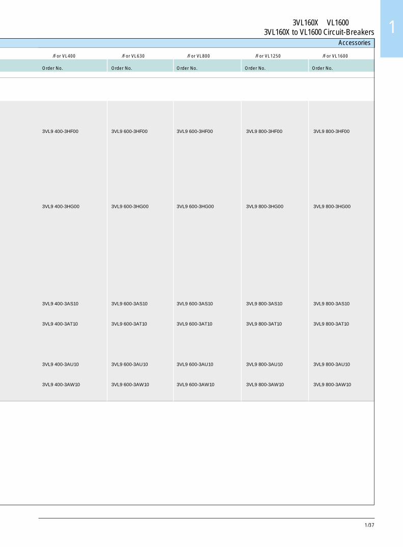
1/37
3VL160X~VL1600断路器3VL160X to VL1600 Circuit-Breakers 1
3VL9 400-3HF00 3VL9 600-3HF00 3VL9 600-3HF00 3VL9 800-3HF00 3VL9 800-3HF00
3VL9 400-3HG00 3VL9 600-3HG00 3VL9 600-3HG00 3VL9 800-3HG00 3VL9 800-3HG00
3VL9 400-3AS10 3VL9 600-3AS10 3VL9 600-3AS10 3VL9 800-3AS10 3VL9 800-3AS10
3VL9 400-3AT10 3VL9 600-3AT10 3VL9 600-3AT10 3VL9 800-3AT10 3VL9 800-3AT10
3VL9 400-3AU10 3VL9 600-3AU10 3VL9 600-3AU10 3VL9 800-3AU10 3VL9 800-3AU10
3VL9 400-3AW10 3VL9 600-3AW10 3VL9 600-3AW10 3VL9 800-3AW10 3VL9 800-3AW10
Accessories
用于 /For VL400 用于 /For VL630 用于 /For VL800 用于 /For VL1250 用于 /For VL1600订货号 订货号 订货号 订货号 订货号Order No. Order No. Order No. Order No. Order No.
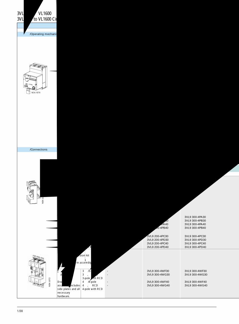
1/38
3VL160X ~VL1600断路器3VL160X to VL1600 Circuit-Breakers
接线方式 /Connections
NSK-1070
NS
K-1
071
附件
操作机构 /Operating mechanisms
NS
K-1
072
用于 /For VL160X 用于 /For VL160 用于 /For VL250订货号 订货号 订货号Order No. Order No. Order No.3 极或 4 极 /3- or 4-pole
储能操作机构Stored energy operator
防护等级 IP 30Degree of protection IP 30带锁具,可用于 3 把挂锁With locking device for 3 padlocks
AC 50/60 Hz V DC V- 24 3VL9 300-3MJ00 3VL9 300-3MJ00 3VL9 300-3MJ0042-48 42-48 3VL9 300-3ML00 3VL9 300-3ML00 3VL9 300-3ML0060 60 3VL9 300-3MS00 3VL9 300-3MS00 3VL9 300-3MS00110-127 110-127 3VL9 300-3MN00 3VL9 300-3MN00 3VL9 300-3MN00220-250 220-250 3VL9 300-3MQ00 3VL9 300-3MQ00 3VL9 300-3MQ00
安装有柱形锁With cylinder lock installed- 24 3VL9 321-3MK00 3VL9 321-3MK00 3VL9 321-3MK0042-48 42-48 3VL9 321-3MM00 3VL9 321-3MM00 3VL9 321-3MM0060 60 3VL9 321-3MT00 3VL9 321-3MT00 3VL9 321-3MT00110-127 110-127 3VL9 321-3MP00 3VL9 321-3MP00 3VL9 321-3MP00220-250 220-250 3VL9 321-3MR00 3VL9 321-3MR00 3VL9 321-3MR00
用于 /For VL160X 用于 /For VL160 用于 /For VL250订货号 订货号 订货号Order No. Order No. Order No.3 极或 4 极 /3- or 4-pole
插入式插座组件Plug-in socket assembly
包括底板,刀型连接件,IP 20 保护母排盖,安装螺丝和底座联锁装置。如果有必要使用相间隔板,则订购。includes base plate, knife contacts, bu-sbar cover for IP 20 protection, moun-ting screws, base interlock. If inter-phasebarriers are desired, order if necessary.
背后连接 /Rear connected3 极 /3-pole 3VL9 100-4PA30 3VL9 200-4PA30 3VL9 300-4PA303 极,带 RCD/3-pole with RCD 3VL9 100-4PB30 3VL9 200-4PB30 3VL9 300-4PB304 极 /4-pole 3VL9 100-4PA40 3VL9 200-4PA40 3VL9 300-4PA404 极,带 RCD/4-pole with RCD 3VL9 100-4PB40 3VL9 200-4PB40 3VL9 300-4PB40
正面连接 /Front connected3 极 /3-pole 3VL9 100-4PC30 3VL9 200-4PC30 3VL9 300-4PC303 极,带 RCD/3-pole with RCD 3VL9 100-4PD30 3VL9 200-4PD30 3VL9 300-4PD304 极 /4-pole 3VL9 100-4PC40 3VL9 200-4PC40 3VL9 300-4PC404 极,带 RCD/4-pole with RCD 3VL9 100-4PD40 3VL9 200-4PD40 3VL9 300-4PD40
抽屉式改装配件Draw-out conversion kit用于插入式组件改装used with plug-in assembly toconvert into
抽屉式组件 3 极 /3-pole - 3VL9 300-4WF30 3VL9 300-4WF30包括侧板和 3 极, 带 RCD - 3VL9 300-4WG30 3VL9 300-4WG30所有必要硬件。 3-pole with RCDDraw-out 4 极 /4-pole - 3VL9 300-4WF40 3VL9 300-4WF40assembly includes 4 极, 带 RCD - 3VL9 300-4WG40 3VL9 300-4WG40side plates and all 4-pole with RCDnecessaryhardware.
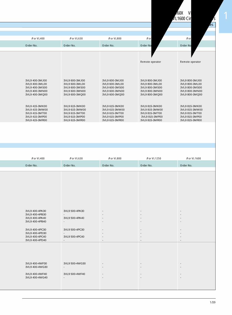
1/39
3VL160X~VL1600断路器3VL160X to VL1600 Circuit-Breakers 1
Accessories
用于 /For VL400 用于 /For VL630 用于 /For VL800 用于 /For VL1250 用于 /For VL1600订货号 订货号 订货号 订货号 订货号Order No. Order No. Order No. Order No. Order No.
远程操作机构 远程操作机构
Remote operator Remote operator
3VL9 400-3MJ00 3VL9 600-3MJ00 3VL9 600-3MJ00 3VL9 800-3MJ00 3VL9 800-3MJ003VL9 400-3ML00 3VL9 600-3ML00 3VL9 600-3ML00 3VL9 800-3ML00 3VL9 800-3ML003VL9 400-3MS00 3VL9 600-3MS00 3VL9 600-3MS00 3VL9 800-3MS00 3VL9 800-3MS003VL9 400-3MN00 3VL9 600-3MN00 3VL9 600-3MN00 3VL9 800-3MN00 3VL9 800-3MN003VL9 400-3MQ00 3VL9 600-3MQ00 3VL9 600-3MQ00 3VL9 800-3MQ00 3VL9 800-3MQ00
3VL9 415-3MK00 3VL9 615-3MK00 3VL9 615-3MK00 3VL9 815-3MK00 3VL9 815-3MK003VL9 415-3MM00 3VL9 615-3MM00 3VL9 615-3MM00 3VL9 815-3MM00 3VL9 815-3MM003VL9 415-3MT00 3VL9 615-3MT00 3VL9 615-3MT00 3VL9 815-3MT00 3VL9 815-3MT003VL9 415-3MP00 3VL9 615-3MP00 3VL9 615-3MP00 3VL9 815-3MP00 3VL9 815-3MP003VL9 415-3MR00 3VL9 615-3MR00 3VL9 615-3MR00 3VL9 815-3MR00 3VL9 815-3MR00
用于 /For VL400 用于 /For VL630 用于 /For VL800 用于 /For VL1250 用于 /For VL1600订货号 订货号 订货号 订货号 订货号Order No. Order No. Order No. Order No. Order No.
3VL9 400-4PA30 3VL9 500-4PA30 - - -3VL9 400-4PB30 - - - -3VL9 400-4PA40 3VL9 500-4PA40 - - -3VL9 400-4PB40 - - - -
3VL9 400-4PC30 3VL9 500-4PC30 - - -3VL9 400-4PD30 - - - -3VL9 400-4PC40 3VL9 500-4PC40 - - -3VL9 400-4PD40 - - - -
3VL9 400-4WF30 3VL9 500-4WG30 - - -3VL9 400-4WG30 - - - -
3VL9 400-4WF40 3VL9 500-4WF40 - - -3VL9 400-4WG40 - - - -
1/40
3VL160X ~VL1600断路器3VL160X to VL1600 Circuit-Breakers
1) 建议为每个断路器订购最多 2 个插座(16 个位置)。1) Maximum of 2 sockets per breaker (16 positions) are recommended to be ordered.2) 建议为每个断路器订购最多 3 个插座(24 个位置)。2) Maximum of 3 sockets per breaker (24 positions) are recommended to be ordered.
附件
用于 /For VL160X 用于 /For VL160 用于 /For VL250订货号 订货号 订货号Order No. Order No. Order No.3 极或 4 极 /3- or 4-pole
抽屉式组件Draw-out assembly带底板 / 插座 / 曲柄,底部联锁装置 /必要的保护罩with base plate/sockets/crank handle,base-interlock/necessary shields
背后连接 /Rear connected3 极 /3-pole - 3VL9 200-4WA30 3VL9 300-4WA303 极,带 RCD/3-pole with RCD - 3VL9 200-4WB30 3VL9 300-4WB304 极 /4-pole - 3VL9 200-4WA40 3VL9 300-4WA404 极,带 RCD/4-pole with RCD - 3VL9 200-4WB40 3VL9 300-4WB40
正面连接 /Front connected3 极 /3-pole - 3VL9 200-4WC30 3VL9 300-4WC303 极,带 RCD/3-pole with RCD - 3VL9 200-4WD30 3VL9 300-4WD304 极 /4-pole - 3VL9 200-4WC40 3VL9 300-4WC404 极,带 RCD/4-pole with RCD - 3VL9 200-4WD40 3VL9 300-4WD40
插入式插座附件Plug-in socket accessory用于在插入式或抽屉式底座上安装附件接线端子For accessory conductors for plug-inbreakers mounted on plug-in or8 个位置 /draw-out bases 8 positions 3VL9 300-4PJ001) 3VL9 300-4PJ001) 3VL9 300-4PJ001)
位置信号发送开关(连接或断开位置信号)Position signaling switch(connected or disconnected)
用于插入式 / 抽屉式底座for plug-in/draw-out bases
1 个常开 /1 个常闭 “C”形开关配件每个底座可接受最多两个配件 3VL9 000-4WL00 3VL9 000-4WL00 3VL9 000-4WL001 NO/1 NC "C" form switch kiteach base can accept up to two kits
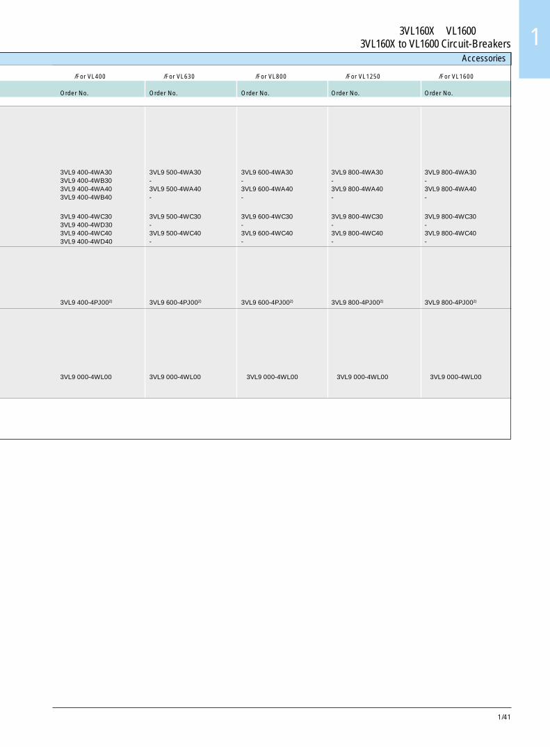
1/41
3VL160X~VL1600断路器3VL160X to VL1600 Circuit-Breakers 1
Accessories
用于 /For VL400 用于 /For VL630 用于 /For VL800 用于 /For VL1250 用于 /For VL1600订货号 订货号 订货号 订货号 订货号Order No. Order No. Order No. Order No. Order No.
3VL9 400-4WA30 3VL9 500-4WA30 3VL9 600-4WA30 3VL9 800-4WA30 3VL9 800-4WA303VL9 400-4WB30 - - - -3VL9 400-4WA40 3VL9 500-4WA40 3VL9 600-4WA40 3VL9 800-4WA40 3VL9 800-4WA403VL9 400-4WB40 - - - -
3VL9 400-4WC30 3VL9 500-4WC30 3VL9 600-4WC30 3VL9 800-4WC30 3VL9 800-4WC303VL9 400-4WD30 - - - -3VL9 400-4WC40 3VL9 500-4WC40 3VL9 600-4WC40 3VL9 800-4WC40 3VL9 800-4WC403VL9 400-4WD40 - - - -
3VL9 400-4PJ002) 3VL9 600-4PJ002) 3VL9 600-4PJ002) 3VL9 800-4PJ002) 3VL9 800-4PJ002)
3VL9 000-4WL00 3VL9 000-4WL00 3VL9 000-4WL00 3VL9 000-4WL00 3VL9 000-4WL00
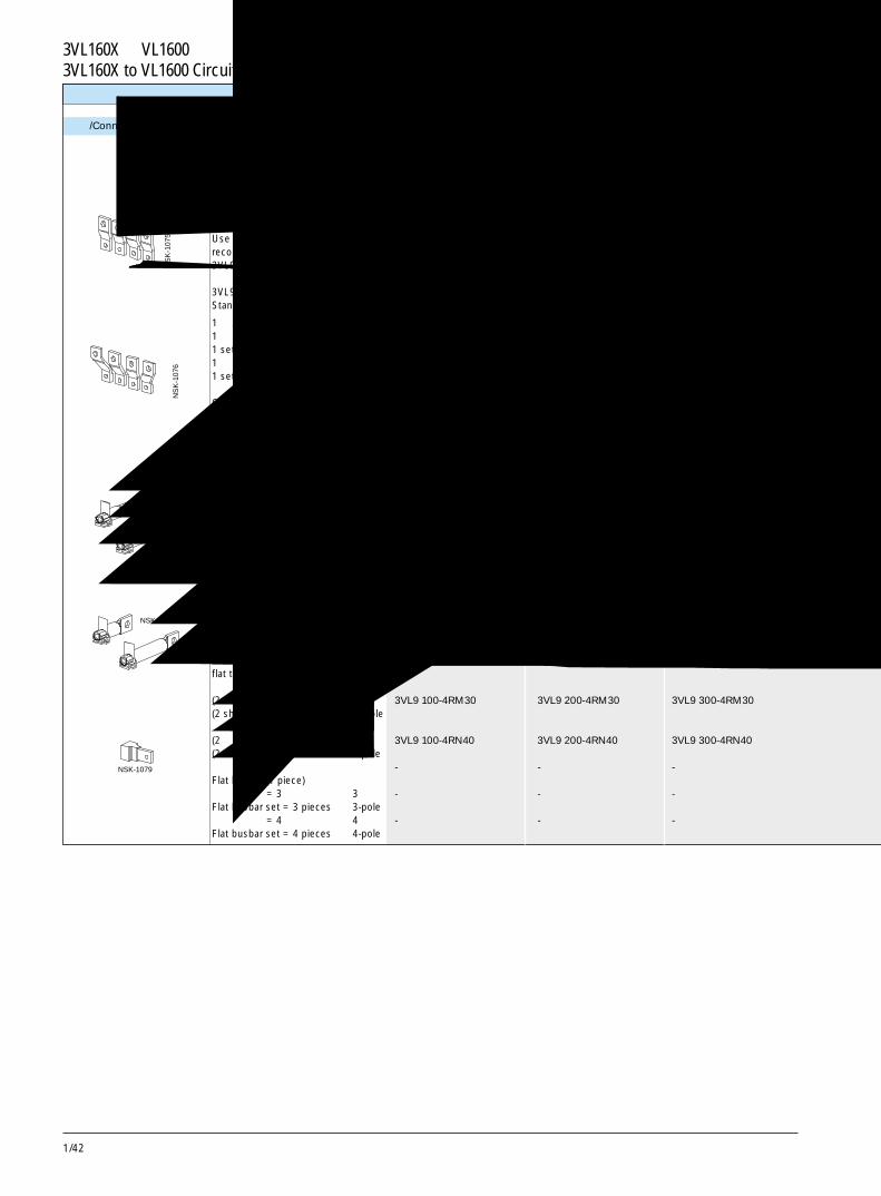
1/42
3VL160X ~VL1600断路器3VL160X to VL1600 Circuit-Breakers
NS
K-1
075
NS
K-1
076
NSK-1077
NSK-1078
NSK-1079
附件
连接 /Connections
用于 /For VL160X 用于 /For VL160 用于 /For VL250订货号 订货号 订货号Order No. Order No. Order No.3 极或 4 极 /3- or 4-pole
正面母排连接件Front busbar connection pieces建议使用螺母定位板Use of nut keeper plate isrecommanded3VL9.00-4TA00,见第 1/12, 1/13 页标准3VL9 . 00-4TA00, see page 1/12, 1/13Standard
1 件 /1 piece 3VL9 200-4EA00 3VL9 200-4EA00 3VL9 300-4EA001 套 = 3 件 3 极 3VL9 200-4EC30 3VL9 200-4EC30 3VL9 300-4EC301 set = 3 pieces 3-pole1 套 = 4 件 4 极 3VL9 200-4EC40 3VL9 200-4EC40 3VL9 300-4EC401 set = 4 pieces 4-pole张开(扩口)Off-set (flared)1 套 = 3 件 3 极 3VL9 200-4ED30 3VL9 200-4ED30 3VL9 300-4ED301 set = 3 pieces 3-pole1 套 = 4 件 4 极 3VL9 200-4ED40 3VL9 200-4ED40 3VL9 300-4ED401 set = 4 pieces 4-pole
背面端子 /Rear terminals短圆杆(1 件) 3VL9 100-4RA00 3VL9 200-4RA00 3VL9 300-4RA00Short length round stock (1 piece)长圆杆(1 件) 3VL9 100-4RB00 3VL9 200-4RB00 3VL9 300-4RB00Long length round stock (1 piece)圆杆配件 /Round stock kit(2 个短的 + 1 个长的) 3 极 3VL9 100-4RC30 3VL9 200-4RC30 3VL9 300-4RC30(2 short + 1 long) 3-pole圆杆配件 /Round stock kit(2 个短的 + 2 个长的) 4 极 3VL9 100-4RF40 3VL9 200-4RF40 3VL9 300-3RF40(2 short + 2 long) 4-pole扁平端子短圆杆(1 件) 3VL9 100-4RK00 3VL9 200-4RK00 3VL9 300-4RK00Short length round stockflat terminal(1 piece)扁平端子长圆杆(1 件) 3VL9 100-4RL00 3VL9 200-4RL00 3VL9 300-4RL00flat terminal (1 piece)扁平端子配件 /Flat terminal kit(2 个短的 + 1 个长的) 3 极 3VL9 100-4RM30 3VL9 200-4RM30 3VL9 300-4RM30(2 short + 1 long) 3-pole扁平端子配件 /Flat terminal kit(2 个短的 + 2 个长的) 4 极 3VL9 100-4RN40 3VL9 200-4RN40 3VL9 300-4RN40(2 short + 2 long) 4-pole扁平母排(1 件) - - -Flat busbar (1 piece)扁平母排套 = 3 件 3 极 - - -Flat busbar set = 3 pieces 3-pole扁平母排套 = 4 件 4 极 - - -Flat busbar set = 4 pieces 4-pole
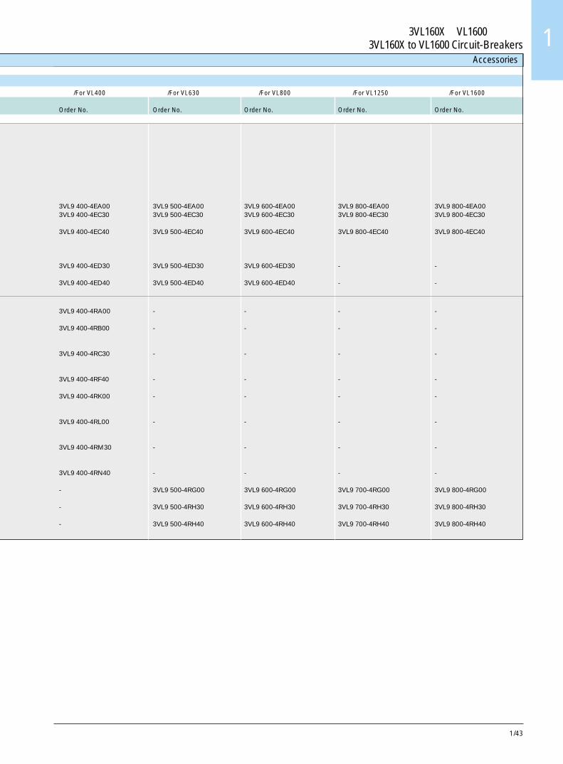
1/43
3VL160X~VL1600断路器3VL160X to VL1600 Circuit-Breakers 1
Accessories
用于 /For VL400 用于 /For VL630 用于 /For VL800 用于 /For VL1250 用于 /For VL1600订货号 订货号 订货号 订货号 订货号Order No. Order No. Order No. Order No. Order No.
3VL9 400-4EA00 3VL9 500-4EA00 3VL9 600-4EA00 3VL9 800-4EA00 3VL9 800-4EA003VL9 400-4EC30 3VL9 500-4EC30 3VL9 600-4EC30 3VL9 800-4EC30 3VL9 800-4EC30
3VL9 400-4EC40 3VL9 500-4EC40 3VL9 600-4EC40 3VL9 800-4EC40 3VL9 800-4EC40
3VL9 400-4ED30 3VL9 500-4ED30 3VL9 600-4ED30 - -
3VL9 400-4ED40 3VL9 500-4ED40 3VL9 600-4ED40 - -
3VL9 400-4RA00 - - - -
3VL9 400-4RB00 - - - -
3VL9 400-4RC30 - - - -
3VL9 400-4RF40 - - - -
3VL9 400-4RK00 - - - -
3VL9 400-4RL00 - - - -
3VL9 400-4RM30 - - - -
3VL9 400-4RN40 - - - -
- 3VL9 500-4RG00 3VL9 600-4RG00 3VL9 700-4RG00 3VL9 800-4RG00
- 3VL9 500-4RH30 3VL9 600-4RH30 3VL9 700-4RH30 3VL9 800-4RH30
- 3VL9 500-4RH40 3VL9 600-4RH40 3VL9 700-4RH40 3VL9 800-4RH40
1/44
3VL160X ~VL1600断路器3VL160X to VL1600 Circuit-Breakers
NSK-1080
NS
K-1
082
NSK-1083
NSK-1084
NSK-1085
附件
用于 /For VL160X 用于 /For VL160 用于 /For VL250订货号 订货号 订货号Order No. Order No. Order No.3 极或 4 极 /3- or 4-pole
卡箍式端子 /Wrap-around terminal软性扁平铜排或电缆用连接器,见第 1/7 页。connector for flexible flat copperbus or cable, see page 1/7
1 件 /1 piece 3VL9 100-4TC00 3VL9 200-4TC00 3VL9 300-4TC001 套 = 3 件 /1 set = 3 pieces 3VL9 100-4TC30 3VL9 200-4TC30 3VL9 300-4TC301 套 = 4 件 /1 set = 4 pieces 3VL9 100-4TC40 3VL9 200-4TC40 3VL9 300-4TC40
端子 1)/Terminal 1 )
仅用于电缆(铝或铜)铝制连接器(镀锡)for cable only (AL or CU)Aluminium body (tin plated)
1 件 /1 piece 3VL9 100-4TD00 3VL9 200-4TD00 3VL9 300-4TD001 套 = 3 件 /1 set = 3 pieces 3VL9 100-4TD30 3VL9 200-4TD30 3VL9 300-4TD301 套 = 4 件 /1 set = 4 pieces 3VL9 100-4TD40 3VL9 200-4TD30 3VL9 300-4TD40
螺母定位板—公制螺纹Nut keeper plate - metric thread带必要绝缘件—与正面母排和电缆接线头一起使用,见第 1/12-1/13页(1 套 =1 件) 3VL9 100-4TA00 3VL9 200-4TA00with necessary insulators - usewith front busbars and cable lug,see page 1/12-1/13 (1 set = 1 piece)
断路器用端子盖Terminal covers for circuit-breaker防护等级 IP 30Degree of protection IP 30用于主端子 1 套 = 2 件for main terminals 1 set = 2 pieces
加长 /Extended 3 极 /3-pole 3VL9 300-8CA30 3VL9 300-8CA30 3VL9 300-8CA30标准 /Standard 3 极 /3-pole 3VL9 300-8CB30 3VL9 300-8CB30 3VL9 300-8CB30加长 /Extended 4 极 /4-pole 3VL9 300-8CA40 3VL9 300-8CA40 3VL9 300-8CA40标准 /Standard 4 极 /4-pole 3VL9 300-8CB40 3VL9 300-8CB40 3VL9 300-8CB40
相间隔板,用于插入式或抽屉式断路器Interphase barriers for circuit-breaker, plug-in or draw-out version
1 套 = 2 件 /1 set = 2 pieces 3VL9 300-8CE00 3VL9 300-8CE00 3VL9 300-8CE00
1) 3VL160X, VL160, VL800和 VL1250 断路器需要使用螺母定位板,见第 1/12-1/13 页。1) For 3VL160X, VL160, VL800 and VL1250 circuit-breakers the nut keeper plates are required, see page 1/12-1/13.
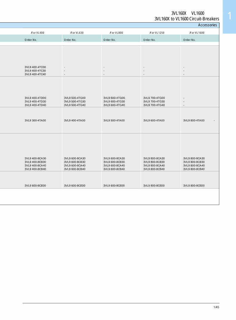
1/45
3VL160X~VL1600断路器3VL160X to VL1600 Circuit-Breakers 1
Accessories
用于 /For VL400 用于 /For VL630 用于 /For VL800 用于 /For VL1250 用于 /For VL1600订货号 订货号 订货号 订货号 订货号Order No. Order No. Order No. Order No. Order No.
3VL9 400-4TC00 - - - -3VL9 400-4TC30 - - - -3VL9 400-4TC40 - - - -
3VL9 400-4TD00 3VL9 500-4TG00 3VL9 600-4TG00 3VL9 700-4TG00 -3VL9 400-4TD30 3VL9 500-4TG30 3VL9 600-4TG30 3VL9 700-4TG30 -3VL9 400-4TD40 3VL9 500-4TG40 3VL9 600-4TG40 3VL9 700-4TG40 -
3VL9 300-4TA00 3VL9 400-4TA00 3VL9 500-4TA00 3VL9 600-4TA00 3VL9 800-4TA00 -
3VL9 400-8CA30 3VL9 600-8CA30 3VL9 600-8CA30 3VL9 800-8CA30 3VL9 800-8CA303VL9 400-8CB30 3VL9 600-8CB30 3VL9 600-8CB30 3VL9 800-8CB30 3VL9 800-8CB303VL9 400-8CA40 3VL9 600-8CA40 3VL9 600-8CA40 3VL9 800-8CA40 3VL9 800-8CA403VL9 400-8CB40 3VL9 600-8CB40 3VL9 600-8CB40 3VL9 800-8CB40 3VL9 800-8CB40
3VL9 600-8CE00 3VL9 600-8CE00 3VL9 600-8CE00 3VL9 800-8CE00 3VL9 800-8CE00
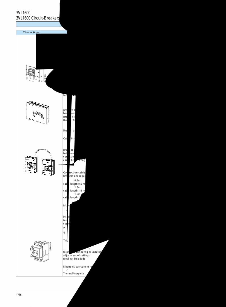
1/46
3VL1600断路器3VL1600 Circuit-Breakers
NS
K-1
086
NS
K-1
089
附件
连接 /Connections
在 3VL160X~VL250 断路器之间推荐的电缆长度为 0.5m。Recommended cable length between 3VL160X to VL250 circuit-breakers is 0.5 m
用于 /For VL160X 用于 /For VL160 用于 /For VL250
订货号 订货号 订货号
Order No. Order No. Order No.
3 极或 4 极 /3- or 4-pole
手柄挂锁装置Handle pad-locking device
用于将断路器手柄锁在“分闸”位置。可使用最多 3 把挂锁,其钩环直径为5-8mm (不含挂锁) 3VL9 300-3HL00 3VL9 300-3HL00 3VL9 300-3HL00to padlock breaker toggle into “OFF”position. Up to 3 padlocks with 5-8 mmshackles may be used(padlocks not included)
杠杆式联锁机构Walking-beamInterlock mechanism
提供两个相邻断路器之间的机械联锁。断路器必须是相同的类型 / 壳架 / 型号。断路器为固定安装 3VL9 300-8LC00 3VL9 300-8LC00 3VL9 300-8LC00provides mechanical interlockingbetween two adjacent circuit-breakers.Breakers must be of like kind/frame/type.Breaker fixed mounted
断路器为插入式 / 抽屉式安装 3VL9 300-8LD00 3VL9 300-8LD00 3VL9 300-8LD00Breaker draw-out/plug-in mounted
电缆联锁系统Cable interlock system
提供两个断路器之间的机械联锁。配件由操作机构板组成,仅用在断路器上 3VL9 300-8LA00 3VL9 300-8LA00 3VL9 300-8LA00provides mechanical interlockingbetween two circuit-breakers. Kitconsist of operator plate for oncircuit-breaker only
连接电缆,用于两个断路器 - 每套需
一个Connection cable for two circuit-breakers-one required per set
电缆长度 0.5m 3VL9 000-8LH10 3VL9 000-8LH10 3VL9 000-8LH10cable length 0.5 m电缆长度 1.0m 3VL9 000-8LH20 3VL9 000-8LH20 3VL9 000-8LH20cable length 1.0 m电缆长度 1.5m 3VL9 300-8LH30 3VL9 300-8LH30 3VL9 300-8LH30cable length 1.5 m
安装螺丝配件 (公制螺纹)Mounting screw kit (metric thread)
包括所有必要硬件,以便将 3 极或 4 极断路器安装到用户准备的表面上。includes all of the necessary hardwareto mount a 3- or 4-pole circuit-breaker tocustomers prepared surface
2 个螺丝配件 /2 screw kit 3VL9 300-8SA20 3VL9 300-8SA20 3VL9 300-8SA20
4 个螺丝配件 /4 screw kit 3VL9 300-8SA40 3VL9 300-8SA40 3VL9 300-8SA40
脱扣器调整密封盖Trip adjustment sealing cover
以防整定值被篡改或在未经授权的情况下被调整 (不含密封件)to prevent tampering or unauthorizedadjustment of settings(seal not included)
电子式过电流脱扣器 - 3VL9 700-8BL00 3VL9 700-8BL00Electronic overcurrent release热 / 磁式 3VL9 300-8BM00 3VL9 300-8BM00 3VL9 300-8BM00Thermal/magnetic
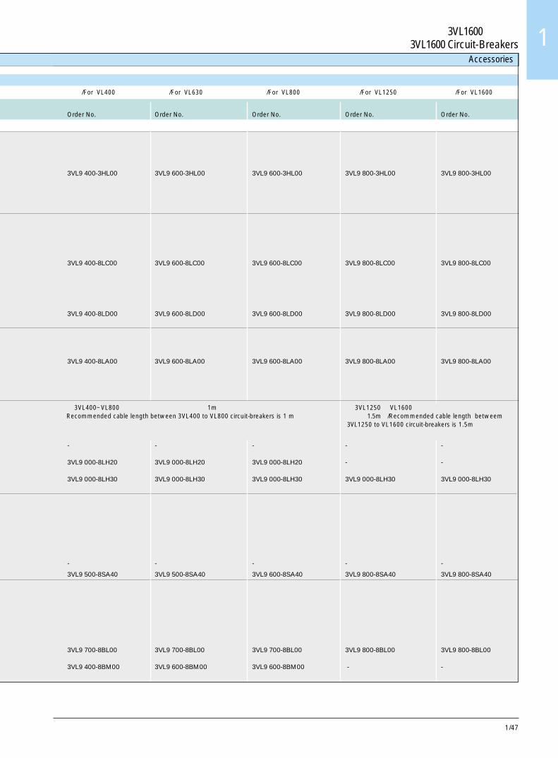
1/47
3VL1600断路器3VL1600 Circuit-Breakers 1
Accessories
用于 /For VL400 用于 /For VL630 用于 /For VL800 用于 /For VL1250 用于 /For VL1600
订货号 订货号 订货号 订货号 订货号
Order No. Order No. Order No. Order No. Order No.
3VL9 400-3HL00 3VL9 600-3HL00 3VL9 600-3HL00 3VL9 800-3HL00 3VL9 800-3HL00
3VL9 400-8LC00 3VL9 600-8LC00 3VL9 600-8LC00 3VL9 800-8LC00 3VL9 800-8LC00
3VL9 400-8LD00 3VL9 600-8LD00 3VL9 600-8LD00 3VL9 800-8LD00 3VL9 800-8LD00
3VL9 400-8LA00 3VL9 600-8LA00 3VL9 600-8LA00 3VL9 800-8LA00 3VL9 800-8LA00
- - - - -
3VL9 000-8LH20 3VL9 000-8LH20 3VL9 000-8LH20 - -
3VL9 000-8LH30 3VL9 000-8LH30 3VL9 000-8LH30 3VL9 000-8LH30 3VL9 000-8LH30
- - - - -
3VL9 500-8SA40 3VL9 500-8SA40 3VL9 600-8SA40 3VL9 800-8SA40 3VL9 800-8SA40
3VL9 700-8BL00 3VL9 700-8BL00 3VL9 700-8BL00 3VL9 800-8BL00 3VL9 800-8BL00
3VL9 400-8BM00 3VL9 600-8BM00 3VL9 600-8BM00 - -
在 3VL400~VL800 断路器之间推荐的电缆长度为 1m。 在 3VL1250和 VL1600 断路器之间推荐的电缆Recommended cable length between 3VL400 to VL800 circuit-breakers is 1 m 长度为1.5m。/Recommended cable length betweem
3VL1250 to VL1600 circuit-breakers is 1.5m
1/48
3VL1600断路器3VL1600 Circuit-Breakers附件
连接 /Connections
用于 /For VL160X 用于 /For VL160 用于 /For VL250
订货号 订货号 订货号
Order No. Order No. Order No.
3 极或 4 极 /3- or 4-pole
柱形锁配件Cylinder lock kits
当断路器处在“分闸”位置时,钥匙可拿下。Key removable when crcuit-breakers in“OFF” position
用于旋转手柄 /Used for rofary handles
锁类型 /lock typesRonis 3VL9 715-8HA00 3VL9 715-8HA00 3VL9 715-8HA00CES 3VL9 711-8HA00 3VL9 711-8HA00 3VL9 711-8HA00
用于储能操作机构Stored energy operators
锁类型 /Lock typesRonis - - -Filli Giussani 3VL9 321-8HA00 3VL9 321-8HA00 3VL9 321-8HA00
手持电子脱扣器测试元件 (蓄电池供电)Hand held electronic release test kit
用于脱扣器 ETU/LCD ETU,以及与Laptop 或 PC 之间的接口 - 3VL9 000-8AK00 3VL9 000-8AK00(battery powered) for ETU/LCD ETUreleases, as well as interface withLaptop or PC
通用电源 (120-240V AC 50/60Hz)Universal power supply(120-240 V AC 50/60 Hz)
适配器 - 当蓄电池不用于电子脱扣器测试元件时使用 - 3VL9 000-8AL00 3VL9 000-8AL00Adapter unit used when battery supplyis not used for electronic release test kit
PROFIBUS 通讯用适配器 COM 10 - 3VL9 000-8AM00 3VL9 000-8AM00PROFIBUS Communicationsadapter COM 10
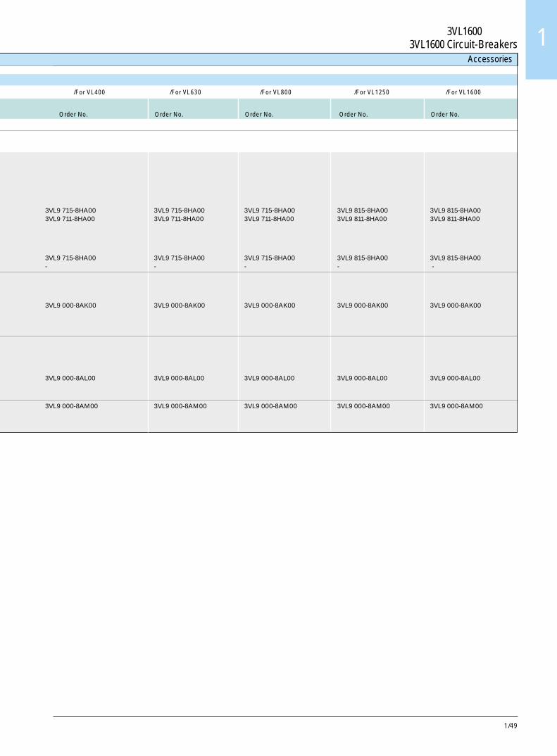
1/49
3VL1600断路器3VL1600 Circuit-Breakers 1
Accessories
用于 /For VL400 用于 /For VL630 用于 /For VL800 用于 /For VL1250 用于 /For VL1600
订货号 订货号 订货号 订货号 订货号
Order No. Order No. Order No. Order No. Order No.
3VL9 715-8HA00 3VL9 715-8HA00 3VL9 715-8HA00 3VL9 815-8HA00 3VL9 815-8HA003VL9 711-8HA00 3VL9 711-8HA00 3VL9 711-8HA00 3VL9 811-8HA00 3VL9 811-8HA00
3VL9 715-8HA00 3VL9 715-8HA00 3VL9 715-8HA00 3VL9 815-8HA00 3VL9 815-8HA00- - - - -
3VL9 000-8AK00 3VL9 000-8AK00 3VL9 000-8AK00 3VL9 000-8AK00 3VL9 000-8AK00
3VL9 000-8AL00 3VL9 000-8AL00 3VL9 000-8AL00 3VL9 000-8AL00 3VL9 000-8AL00
3VL9 000-8AM00 3VL9 000-8AM00 3VL9 000-8AM00 3VL9 000-8AM00 3VL9 000-8AM00
1/50
3VL1600断路器3VL1600 Circuit-Breakers
用于 /For VL160X 用于 /For VL160 用于 /For VL250
订货号 订货号 订货号
Order No. Order No. Order No.
3 极或 4 极 /3- or 4-pole
3VL9 300-8BC00 3VL9 300-8BC00 3VL9 300-8BC00
3VL9 300-8BG00 3VL9 300-8BG00 3VL9 300-8BG00
- 3VL9 300-8BH00 3VL9 300-8BH00
3VL9 300-8BD00 3VL9 300-8BC00 3VL9 300-8BC00
3VL9 300-8BD00 3VL9 300-8BD00 3VL9 300-8BD00
- 3VL9 300-8BH00 3VL9 300-8BH00
- 3VL9 300-8BJ00 3VL9 300-8BJ00
- - -
柜门开孔面框Cover frame for door cutout
IP 40 固定安装式或插入安装式断路器Circuit-breaker fixed or plug-inmounted
IP 40 带旋转操作机构或储能操作机构的断路器Circuit-breaker with rotary orstored energy operator
IP 20 抽屉安装式断路器。配件含有面框和必要的加长框(如使用手柄或储能操作机构则不用)Circuit-breaker draw-outmounted. Kit contains coverframe and necessary extendedescutcheon (not used if handleor stored energy operator isused)
IP 40 固定安装式或插入安装式断路器,Circuit-breaker fixed or plug-inmounted with带 RCD 断路器面框RCD Breaker cover frameRCD 面框 /RCD cover frame
IP 40 装有 RCD 和旋转驱动机构的断路器。配件含有面框和加长框。Circuit-breaker mounted withRCD and rotary drive. Kitcontains cover frame andextended escutcheon装有 RCD 和储能操作机构的断路器。配件含有面框和必要的加长框。Circuit-breaker mounted withRCD and stored energyoperator. Kit contains coverframe and necessary extendedescutcheon
扳动手柄加长件Toggle handle extension
NSK-1091
附件
连接 /Connections
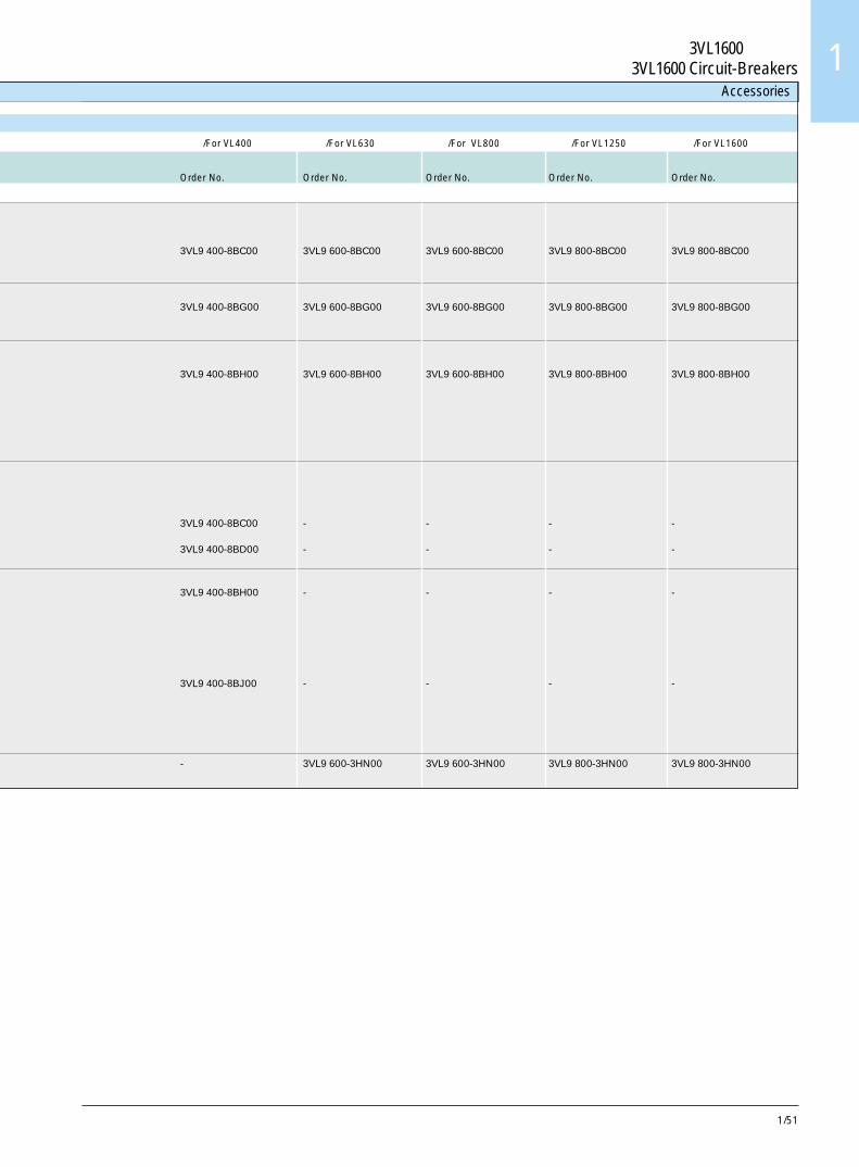
1/51
3VL1600断路器3VL1600 Circuit-Breakers 1
用于 /For VL400 用于 /For VL630 用于 /For VL800 用于 /For VL1250 用于 /For VL1600
订货号 订货号 订货号 订货号 订货号
Order No. Order No. Order No. Order No. Order No.
3VL9 400-8BC00 3VL9 600-8BC00 3VL9 600-8BC00 3VL9 800-8BC00 3VL9 800-8BC00
3VL9 400-8BG00 3VL9 600-8BG00 3VL9 600-8BG00 3VL9 800-8BG00 3VL9 800-8BG00
3VL9 400-8BH00 3VL9 600-8BH00 3VL9 600-8BH00 3VL9 800-8BH00 3VL9 800-8BH00
3VL9 400-8BC00 - - - -
3VL9 400-8BD00 - - - -
3VL9 400-8BH00 - - - -
3VL9 400-8BJ00 - - - -
- 3VL9 600-3HN00 3VL9 600-3HN00 3VL9 800-3HN00 3VL9 800-3HN00
Accessories
1/52
3VL160X~VL400断路器 3VL160X to VL400 Circuit-Breakers带剩余电流检测 (RCD) with Residual Current Detection (RCD)选型和订货信息 Selection and ordering information
RCD模块是为用户自行安装而设计的。装配好的3VL断路器与RCD模块的组合可反向得电。带有RCD模块的(3极和4极) 3VL断
路器可装有辅助开关,报警开关,欠压脱扣器和分励脱扣器,这取决于安装的附件空间。详情见下表。
The RCD module is designed forcustomer installation.The assembled combination of 3VLcircuit-breaker and RCD modulemay be reverse fed.The (3- and 4-pole) 3VL circuit-breakers with RCD module
applied may have auxiliaryswitches, alarm switches,undervoltage and shunt releasesinstalled dependent on availableaccessory space. See detailsbelow.
RCD模块 /RCD module线路保护用断路器, 额定电流 In 漏电电流 I∆n 可 延迟时间 td 额定工作电 3 极断路器 4 极断路器仅限 TM,起动器,隔离开关 调节量 可调 压 Ue
Circuit-breakers Rated Differential cur- Delay time td Rated Circuit-breaker Circuit-breakerfor line protection, current rents I∆n adjustable adjustable operational 3-pole 4-polefor TM, starter, non-auto only In increments voltage Ue
3 极和 4 极 A A s AC V3- and 4-pole 订货号 订货号
Order No. Order No.
VL160X 瞬时VL160X 0.03 Instantaneous(底部安装)/(bottom mounting)1 ) 125 0.10 0.06 127-480 3VL9 112-5GA30 3VL9 112-5GA40(左侧安装)/(left side mounting)2) 0.30 0.10 127-480 3VL9 112-5GB30 3VL9 112-5GB40
0.50 0.25VL160 160 1.00 0.50 127-480 3VL9 216-5GC30 3VL9 216-5GC40
3.00 1.00 230-690 3VL9 216-5GD30 3VL9 216-5GD40VL250 250 127-480 3VL9 325-5GE30 3VL9 325-5GE40
230-690 3VL9 325-5GF30 3VL9 325-5GF40VL400 400 127-480 - 3VL9 440-5GG40
230-690 - 3VL9 440-5GH40
带RCD模块的断路器 /Circuit-Breaker with RCD module
线路保护用断路器, 额定电流 In 漏电电流 I∆n 可 延迟时间 td 额定工作电 3 极断路器 4 极断路器调节量 可调 压 Ue Circuit-breaker Circuit-breaker
Circuit-breakers Rated Differential cur- Delay time td Rated 3-pole 4-polefor line protection, current rents I∆n adjustable adjustable operational 订货号带 ”Z” 订货号带 ”Z”仅限 TM 3 极和 4 极 In increments voltage Ue Order No. with ”Z” Order No. with ”Z”for TM only 3- and 4-pole 3VL.... - . D... - .... 3VL.... - . E... - ....
A A s AC V -Z -Z以及附加的订货代码 以及附加的订货代码and additional order code and additional order code��� ���
瞬时VL160X 0.03 Instantaneous(底部安装)/(bottom mounting)1 ) 125 0.10 0.06 127-480 A 0 11) A 0 11)(左侧安装)/(left side mounting)2 ) 0.30 0.10 127-480 - -
0.50 0.25
VL160 160 1.00 0.50 127-480 A 0 1 A 0 13.00 1.00 230-690 A 0 2 A 0 2
VL250 250 127-480 A 0 1 A 0 1230-690 A 0 2 A 0 2
VL400 400 127-480 - A 0 1230-690 - A 0 2
1) 只有右极和 N 极 (4 极) 可安装附件,见第 1/14-1/15 页。
Only right and N-pole (4-pole) accessory pocket is available for accessories, see page 1/14-1/15.
2) 该订货号提供侧面安装的安装零件 (需单独订购 RCD)。
The kit alows RCD to mount on the leftside of the MCCB (order RCD separatly).

1/53
3VL160X~VL400断路器 3VL160X to VL400 Circuit-Breakers带剩余电流检测 (RCD) with Residual Current Detection (RCD) 1RCD 模块与 DI 模块相对应。
应用
在 TT、IT 和 TN 系统中的人员安全性(整定到 I∆n = 30mA,td 瞬时)
保护线路和设备以免受到因接地故障引起的过载和损坏(接地故障保护)
当对地泄漏电流超过预整定的动作电流和延时整定值时,该装置利用所有相电流的矢量和使断路器脱扣。
特性
● 用户易于安装● 侧部安装配件符合 DIN 50 023,用于 3VL160X 断路器,订货号带有 3VL9 112-5GA30/ 3VL9 112-5GA40
● 使用脱扣按钮 (Push-to-Trip),可对安装的 RCD 进行功能检查。
● 复位 /脱扣按钮弹出(在复位 /脱扣按钮复位前,断路器不会再扣。)
● 断路器脱扣器远程脱扣用电路,无需外部辅助电压源 (用于 3VL160~VL400 断路器)。用户将提供遥控开关和双绞线电缆
● LED指示器可实现对RCD装置的目视监视- 绿色 I∆≤ I∆n 的 25%- 绿色 + 黄色
25% I∆n< I∆ = 可调 I∆n 的 50%- 绿色 + 黄色 + 红色 I∆ ≥ 可调 I∆n 的 50%
● 3VL160~VL400 断路器报警开关转换(C0)触头将表明,RCD已使断路器脱扣。
● 3VL160~VL400 断路器可提供690V AC 应用。
● 切断电源功能可进行介电性能测试,无需拆除电缆。
● 增设 RCD 不会影响断路器的功能特性。
● 无需外部电压。
选型和订货信息 Selection and ordering information
The RCD module corresponds tothe DI module.
ApplicationSafety of persons in TT, IT and TNSystems (set to I∆n = 30 mA, td
instantaneous).Protection of line and equip- mentagainst overload and damage byearth faults (earth- faultprotection).Using vectorial summation of allphase currents this device tripsthe circuit-breaker when earthleakage currents exceed thepreset pick-up and time delaysettings.
Attributes● Easy mounting by cus tomer● Side mounting kit for DIN 50
023 for 3VL160X circuit-breakerorder with 3VL9 112-5GA30/3VL9 112-5GA40
● Push-to-Trip Button permitsfunctional checkout of in- stalledRCD
● Pop-up reset/trip button (thatwill not allow circuit- breakerrelatching until reset/trip buttonis reset)
● Circuitry for remote tripping ofcircuit-breaker release unitwithout the need for externalsource of additional voltage (for3VL160 to VL400 circuit-breakers). Customer to supplyremote control switch andtwisted pair cable
● LED indicators that allow forvisual monitoring of RCD unit- Green
I∆≤ 25% I∆n
- Green + Yellow25% I∆n< I∆ = 50% of theadjusted
- Green + Yellow + RedI∆ ≥ 50% of the adjusted I∆n
● 3VL160 to VL400circuit-breakers alarm switchchangeover (C0) contacts toindicate that RCD has trippedthe circuit-breaker
● 3VL160 to VL400circuit-breakers 690 V ACapplication available
● Power disconnect allows fordielectric testing withoutremoving cables
● Circuit-breaker functionalcharacteristics not effected byaddition of RCD
● No external voltage required.

1/54
3VL160X~VL1600断路器 3VL160X to VL1600 Circuit-Breakers3 极和 4 极 3- and 4- Pole
型号 /Type VL160X VL160 VL250 VL400 VL630 VL800 VL1250 VL1600
最大额定电流 In
Max. rated current In
与断路器壳架等级有关 A 160 160 250 400 630 800 1250 1600depending on the version
额定绝缘电压Ui符合 IEC 60 947-2标准Rated insolation voltage Ui acc. to IEC 60 947-2
主导电回路 AC V 750 750 750 750 750 750 750 750Main conducting paths
辅助电路 AC V 690 690 690 690 690 690 690 690Auxiliary circuits
额定冲击耐受电压Uimp
Rated impulse withstand voltage Uimp
主导电回路 kV 8 8 8 8 8 8 8 8Main conducting paths
辅助电路 kV 4 4 4 4 4 4 4 4Auxiliary circuits
额定工作电压Ue
Rated operational voltage Ue
IEC AC kV 690 690 690 690 690 690 690 690
NEMA AC kV 600 600 600 600 600 600 600 600允许环境温度 °C -25~+75 -25~+75 -25~+75 -25~+75 -25~+75 -25~+75 -25~+75 -25~+75Permissible ambient temperature各种环境温度用的允许负荷Permissible loads for various ambient temperatures断路器附近,与断路器的额定电流有关close to the circuit-breaker, related to the rated current of the circuit-breaker
- 线路保护用断路器 在 at 40°C 时 % 100 100 100 100 100 100 100 100Circuit-breakers for line protection at 在 at 50°C 时 % 100 100 100 100 100 100 100 100
在 at 60°C 时 % 93 93 93 93 93 95 95 95在 at 70°C 时 % 86 86 86 86 86 86 86 80
- 具有 ETU 脱扣器的断路器 在 at 40°C 时 % 100 100 100 100 - - - -Circuit-breakers with ETU at 在 at 50°C 时 % 100 100 100 100 - - - -
在 at 60°C 时 % 93 93 93 93 - - - -在 at 70°C 时 % 86 86 86 86 - - - -
- 起动器组合和隔离保护用断路器 在 at 40°C 时 % 100 100 100 100 100 100 100 100Circuit-breakers for starter at 在 at 50°C 时 % 100 100 100 100 100 100 100 100combmaions and non-automatic breaker 在 at 60°C 时 % 93 93 93 93 93 95 95 95
在 at 70°C 时 % 86 86 86 86 86 86 86 80
额定短路分断能力 (DC)Rated short-circuit breaking capacity (DC)不用于电动机保护用 3VL 断路器not for 3VL circuit-breakers for motor protection时间常数 t = 10ms/Time constant t = 10 ms1 极导通 2极串联的 3 极串联的回路 导电回路 导电回路1 conducting 2 conducting 3 conductingpath paths in series paths in series用于 VL160X~VL1600 断路器 /for VL160X to VL1600可达 /up to 250V DC 440 VDC 600V DC kA 30 30 30 30 30 30 30 30
NEMA时间常数 t = 8ms/Time constant t = 8 ms1 极导通 2极串联的回路 导电回路1 conducting 2 conducting path paths in series250V DC - kA 30 30 30 30 30 30 30 30- 250V DC kA 30 30 30 30 30 30 30 30
主开关特性符合 IEC 60 947标准 是 是 是 是 是 是 是 是Main switch-characteristics acc. to IEC 60 947-2 yes yes yes yes yes yes yes yes包括可锁定的旋转驱动机构in combination with lockable rotary drives
急停开关特性 是 是 是 是 是 是 是 是EMERGENCY-STOP switch-characteristics yes yes yes yes yes yes yes yes符合 DIN VDE 0113 标准acc. to DIN VDE 0113
额定短路分断能力 额定短路分断能力见第 1/60 页上的表Rated short-circuit breaking capacity Rated short-circuit breaking capacity see table on page 1/60符合 IEC 60 947-2(在 50/60Hz 时)acc. to IEC 60 947-2 (at 50/60 Hz)
技术数据 Technical data
3VL160X~VL1600断路器 3VL160X to VL1600 Circuit-Breakers3 极和 4 极 3- and 4- Pole

1/55
3VL160X~VL1600断路器 3VL160X to VL1600 Circuit-Breakers3 极和 4 极 3- and 4- Pole 1
NS1-5154a
90 90
NSK-1489
30 30
operating cycles
型号 /Type VL160X VL160 VL250 VL400 VL630 VL800 VL1250 VL1600
寿命 操作循环次数 20000 20000 20000 20000 10000 5000 3000 3000Endurance 20000 20000 20000 20000 10000 5000 3000 3000
最大操作频率 1/h 120 120 120 120 60 60 30 30Max. switching frequency
导线截面和主导线的端子类型 卡箍式 卡箍式 扁平 扁平 扁平 扁平 扁平 扁平Conductor cross-sections and Wrap Wrap Flat Flat Flat Flat Flat Flatterminal types for main conductors around around
卡箍式端子Wrap around terminal单股或多股电缆 仅为铜 mm2 2.5-70 2.5-70 25-150 50-240 - - - -Solid or stranded cable Copper only带端部套筒的细多股电缆 mm2 2.5-50 2.5-50 25-120 50-185 - - - -Finely stranded with end sleeve母排 /Busbar mm 12 x 10 12 x 10 17 x 10 25 x 10 - - - -端子的拧紧力矩 Nm 3/6 3/6 10 25 - - - -Tightening torque for terminals
电缆用铝端子Aluminium terminal for cable单股或多股电缆 铜或铝 mm2 10-95 10-95 25-185 50-240 - - - -Solid or stranded cable Cu or Al多路进线槽 铜或铝 mm2 2 件 2 件 3 件 4 件 -Multiple feed-in cavity Cu or Al 50-120 95-120 50-240 50-240
铝端子的拧紧力矩 铜或铝 Nm 6/14 6/14 31 56/31 34 42 42 -Tightening torque for Al. terminal Cu or Al安装螺丝拧紧力矩 Nm - - 11 15/15 15 15 24 -Mounting screw tightening torque
螺栓栓接的母排 铜或铝 mm 17 x 10 24 x 10 24 x 10 32 x 10 40 x 10 3x40x5 2x50x10 已提供Bolted busbars Cu or Al螺栓,与螺母板一起使用 M 5 M 5 M 8 M 8 M 6 M 8 M 10 -Bolt for use with nut plate母排连接件的拧紧力矩 Nm 4.5 4.5 11 15 15 15 24 -Tightening torque for busbar connection pieces
控制电路用导线截面,带端子连接或端子板Conductor cross-sections for control circuits with terminal connection or terminal strip
单股线 /Solid mm2 0.75-1.5 0.75-1.5 0.75-1.5 0.75-1.5 0.75-1.5 0.75-1.5 0.75-1.5 0.75-1.5带端部套筒的细多股线 mm2 0.75-1.0 0.75-1.0 0.75-1.0 0.75-1.0 0.75-1.0 0.75-1.0 0.75-1.0 0.75-1.0Finely stranded with end sleeve安装螺丝用拧紧力矩 Nm 1 1 1 1 1 1 1 1Tightening torque for fitting screws
最大额定电流时,每个断路器的功率损耗Power loss per circuit-breaker at max. rated current
线路保护 /Line protection TM0.8-1.0 W 12-70 15-48 32-80 60-175 85-230 - - -线路保护 /Line protection ETU 或 LCD ETU W - 40 60 90 160 250 210 260对于隔离开关 W 40 40 60 90 160 250 210 260for non-automatic breaker用于电动机保护 W - 40 60 90 160 - - -for motor protection
允许安装位置Permissible mounting position
辅助开关和报警开关 3SB34 00-0K-3SB3400-0J
Auxiliary and alarm switches 3SB34 00-0K-3SB3400-0J
约定发热电流 Ith A 10 10 10 10 10 10 10 10Conventional free-air thermal current Ith
额定接通能力 A 10 10 10 10 10 10 10 10Rated making capacity
技术数据 Technical data

1/56
3VL160X~VL1600断路器 3VL160X to VL1600 Circuit-Breakers3 极和 4 极 3- and 4- Pole技术数据 Technical data
型号 /Type VL160X VL160 VL250 VL400 VL630 VL800 VL1250 VL1600
AC (AC-15)
额定工作电压 V 24 48 110 230 400 600Rated operational voltage
额定工作电流 AC-12 A 10 10 10 10 10 10Rated operational current AC-15 A 6 6 6 6 3 1
DC (DC-13)
额定工作电压 V 24 48 110 230Rated operational voltage
额定工作电流 DC-12 A 10 5 2.5 1Rated operational current DC DC-13 A 3 1.5 0.7 0.3
后备熔断器 /微型断路器 A 10 TDZ / 10Back-up fuse/Miniature circuit-breaker
专用指示开关旋转驱动机构,超前动作辅助开关Special application indication switches rotary drive, leading auxiliary switch
额定发热电流 Ith A 2 2 2 2 2 2 2 2Rated thermal current Ith
额定接通能力 A 2 (ind 0.5) 2 (ind 0.5) 2 (ind 0.5) 2 (ind 0.5) 2 (ind 0.5) 2 (ind 0.5) 2 (ind 0.5) 2 (ind 0.5)Rated making capacity额定工作电压 AC V 220 220 220 220 220 220 220 220Rated operational voltage额定工作电流 A 2 2 2 2 2 2 2 2Rated operational current额定分断能力,感性,p.f. 0.7 A 0.5 0.5 0.5 0.5 0.5 0.5 0.5 0.5Rated breaking capacity, inductive, p.f. 0.7额定分断能力 A 2 2 2 2 2 2 2 2Rated breaking capacity后备熔断器 (快速动作型) A 2 2 2 2 2 2 2 2Back-up fuse (quick response)专用指示开关,插入式位置指示开关.Special application indication switches plug-in position switch
额定发热电流 Ith A 16 16Rated thermal current Ith
额定接通能力 A 16 10Rated making capacity额定工作电压 AC V 250 400Rated operational voltage额定工作电流 A 16 10Rated operational current额定分断能力,感性,p.f. 0.7 A 4 4Rated breaking capacity, inductive, p.f. 0.7额定分断能力 A 16 10Rated breaking capacity后备熔断器(快速动作型) A 16 10Back-up fuse (quick response)
专用指示开关,RCD 报警开关Special application indication switches RCD alarm switch
额定发热电流 Ith A 2 2 2Rated thermal current Ith
额定接通能力 A 2 2 2Rated making capacity额定工作电压 AC V 250 250 250Rated operational voltage额定工作电流 A 2 2 2Rated operational current额定分断能力,感性,p.f. 0.7 A 0.5 0.5 0.5Rated breaking capacity, inductive, p.f. 0.7额定分断能力 A 2 2 2Rated breaking capacity后备熔断器(快速动作型) A 2 2 2Back-up fuse (quick response)
1/57
3VL160X~VL1600断路器 3VL160X to VL1600 Circuit-Breakers3 极和 4 极 3- and 4- Pole 1技术数据 Technical data
型号 /Type VL160X VL160 VL250 VL400 VL630 VL800 VL1250 VL1600
脱扣器 第 1 组 - VL160X~VL400 第 2组 - VL630~VL1600Releases Group No. 1 - VL160X to VL400 Group No. 2 - VL630 to VL1600
欠压脱扣器(“r”脱扣器)Undervoltage releases (“r”releases)
工作电压: Us Us Us Us Us Us Us Us
Response voltage:降释放(断路器已脱扣) V 0.35-0.70 0.35-0.70 0.35-0.70 0.35-0.70 0.35-0.70 0.35-0.70 0.35-0.70 0.35-0.70Drop (breaker tripped)吸合(断路器可接通) V 0.85-1.1 0.85-1.1 0.85-1.1 0.85-1.1 0.85-1.1 0.85-1.1 0.85-1.1 0.85-1.1Pick-up (breaker may be switched on)下列情况下的功率消耗(持续工作):Power consumption (continuous operation) at:110-127 V AC, 50/60 Hz VA 4.5 4.5 4.5 4.5 4.5 4.5 4.5 4.5220-250 V AC, 50/60 Hz VA 4.5 4.5 4.5 4.5 4.5 4.5 4.5 4.5208 V AC, 50/60 Hz VA 4.5 4.5 4.5 4.5 4.5 4.5 4.5 4.5277 V AC, 50/60 Hz VA 4.5 4.5 4.5 4.5 4.5 4.5 4.5 4.5
380-415 V AC, 50/60 Hz VA 4.5 4.5 4.5 4.5 4.5 4.5 4.5 4.5440-480 V AC, 50/60 Hz VA 4.5 4.5 4.5 4.5 4.5 4.5 4.5 4.5500-525 V AC, 50/60 Hz VA 4.5 4.5 4.5 4.5 4.5 4.5 4.5 4.5600 V AC, 50/60 Hz VA 4.5 4.5 4.5 4.5 4.5 4.5 4.5 4.5
12 V DC W 3.5 3.5 3.5 3.5 3.5 3.5 3.5 3.524 V DC W 3.5 3.5 3.5 3.5 3.5 3.5 3.5 3.548 V DC W 3.5 3.5 3.5 3.5 3.5 3.5 3.5 3.5
60 V DC W 3.5 3.5 3.5 3.5 3.5 3.5 3.5 3.5110-127 V DC W 3.5 3.5 3.5 3.5 3.5 3.5 3.5 3.5220-250 V DC W 3.5 3.5 3.5 3.5 3.5 3.5 3.5 3.5
最大分闸时间 ms 50 50 50 50 50 50 50 80Max. opening time
分励脱扣器(“f”脱扣器)Shunt releases (“f”releases)
工作电压:/Response voltage: Us Us Us Us Us Us Us Us
动作(断路器脱扣) V 0.7-1.1 0.7-1.1 0.7-1.1 0.7-1.1 0.7-1.1 0.7-1.1 0.7-1.1 0.7-1.1Pick-up (breaker tripped)
下列情况下的功率消耗(短时) :Power consumption (short-time) at:48-60 V AC, 50/60 Hz VA 158-200 158-200 158-200 158-200 300-480 300-480 300-480 300-480110-127 V AC, 50/60 Hz VA 136-158 136-158 136-158 136-158 302-353 302-353 302-353 302-353208-277 V AC, 50/60 Hz VA 274-350 274-350 274-350 274-350 330-349 330-349 330-349 330-349380-600 V AC, 50/60 Hz VA 158-237 158-237 158-237 158-237 243-384 243-384 243-384 243-384
12 V DC W 110 110 110 110 50 50 50 5024 V DC W 110 110 110 110 360 360 360 36048-60 V DC W 110-172 110-172 110-172 110-172 500-820 500-820 500-820 500-820
110-127 V DC W 220-254 220-254 220-254 220-254 302-353 302-353 302-353 302-353220-250 V DC W 97-110 97-110 97-110 97-110 348-397 348-397 348-397 348-397
最大分闸时间 ms 50 50 50 50 50 50 50 50Max. opening time
最大负荷持续时间 s 自动断电Max. load duration s interrupts automatically
1/58
3VL160X~VL1600断路器 3VL160X to VL1600 Circuit-Breakers3 极和 4 极 3- and 4- Pole技术数据 Technical data
允许安全间隙的定义与断路器的距离A: 到导电回路 (包括无遮挡物或有接地金属)B: 断路器相端子到底墙C: 断路器侧部到侧墙(包括无遮挡物或有接地金属)D: 到非导电部件,最小 3mm 厚绝缘(绝缘件,绝缘棒,上漆板)注:当电压>600V AC, 500V DC 时需要装端子盖。
Definitions of the permitted safety clearance distances distance from thecircuit-breakerA: to conductive paths (blank and earthed metal)B: circuit-breaker phase terminal to bottom wallC: side of circuit-breaker to side walls (blank and earthed metal)D: to non-conductive parts minimum of 3 mm thick insulation (insulator,
insulated bar, painted plate)Note: Terminal covers regnired >600V AC, 500V DC.
型号 /Type VL160X VL160 VL250 VL400 VL630 VL800 VL1250 VL1600
同步电动机操作机构 x x x x x x O OSynchronizable motorized operating mechanism
工作范围 /Operating range V 0.85-1.1在Us 时的最小命令持续时间 ms 50Minimum command duration at Us
全部合闸时间 /Total closing time ms <100 <5000 <5000分断时间 /Break time s <5充电时间 /Charging time s <5重合闸间隙 /Reclosing after approx. ms 50
最大允许开关频率 /Max. permissible operating frequency 1/h 120 120 120 120 60 60 30 30
最长命令持续时间 /Max. command duration ms 连续 /Continuous
功率消耗 /Power consumption VA/W <500
额定控制电源 /Rated control supply 50/60 Hz AC V - 48 60 110-127 220-250电压Us/Voltage Us DC V 24 48 60 110-127 220-250
后备熔断器或微型断路器(慢响应) ABack-up fuse orminiature circuit-breaker (slow response) 20 16 10 6 2
x = 可用 /available O = 电动机操作机构 /Motor operator
灭弧室上方所需空间 /Space required above arc chutes
断路器 分断能力 最小外壳Circuit-breaker Switching 体积 A A B C D
capacity Minimum ≤ 415 V >415 - 690 V ≤ 690 V ≤ 690 V ≤ 690 V型号 Enclosure 不带盖 不带盖 带盖Type Volume without without with
m3 covers covers covers
VL160X 标准 /Standard高 /High 0.011 35 70 35 25 25 35
VL160 标准 /Standard高 /High 0.011 50 100 50 25 25 35极高 /Very high
VL250 标准 /Standard高 /High 0.015 50 100 50 25 25 35极高 /Very high
VL400 标准 /Standard高 /High 0.36 50 100 50 25 25 35极高 /Very high
VL630 标准 /Standard高 /High 0.18 50 100 50 25 25 35极高 /Very high
VL800 标准 /Standard高 /High 0.22 50 100 50 25 25 35极高 /Very high
VL1250 标准 /Standard高 /High 0.22 70 100 70 30 30 50极高 /Very high
VL1600 标准 /Standard高 /High 请向西门子咨询 /Consult Siemens
极高 /Very high

1/59
3VL160X~VL1600断路器 3VL160X to VL1600 Circuit-Breakers3 极和 4 极 3- and 4- Pole 1
推荐线路 最大允许直流电压 Ue 说明Recommended circuit Maximum Remarks
permissibleDC voltage Ue
用于 3 极和 4 极断路器For 3- and 4-pole circuit-breakers
`250 V DC 双极通断Double pole switching如果没有接地故障危险,或者如果任何接地故障能够立即消除(接地故障监控),则最大允许直流电压可达 600V。If there is no risk of an earth fault, or if any earth fault can be immediatelyeliminated (earth fault monitoring), the maximum permissible DC voltagecan be 600 V.
440 V DC 双极通断(接地系统)Double pole switching (earthed system)接地极必须始终是单个导电回路,因而出现接地故障时,两个回路始终是串联的。The earthed pole must always be assigned to the individual conducting path,so that two paths are always in series in the event of an earth fault.
600 V DC 单极通断(接地系统)Single pole switching (earthed system)3 个导电回路串联。3 conducting paths in series.接地极必须是非开关的导电回路。The earthed pole must be assigned to the non-switched conducting path.
750 V DC 单极通断(接地系统)Single pole switching (earthed system)4 个导电回路串联。4 conducting paths in series.接地极必须是非开关的导电回路。The earth pole must be assigned to the non-switched conducting path.
短路接通能力,短路分断能力和相关功率因数之间的关系(符合 IEC 60 947标准)Relation between short-circuit making capacity, short-circuit breaking capacity and the related power factor
(acc. to IEC 60 947)
短路分断能力 功率因数 短路接通能力的最小值(短路分断能力的 n 倍)Short-circuit breaking capacity Power Minimum value for short-circuit makingI factor capacity (n times short-circuit breaking capacity)A p.f n x I4500 < I ≤ 6000 0.7 1.5 x I6000 < I ≤ 10000 0.5 1.7 x I10000 < I ≤ 20000 0.3 2.0 x I20000 < I ≤ 50000 0.25 2.1 x I50000 < I 0.2 2.2 x I
技术数据 Technical data
直流通断VL160X~VL630具有TM,起动器及隔离开关也可用于通断直流。但ETU 不能用于直流。带电子式数字脱扣器的 V L 8 0 0~VL1600 断路器不适合通断直流。在通断直流时,必须考虑每个导电回路的最大允许直流电压。在电压高于250V时,要求将2个或3 个导电回路串联使用。
由于电流必须流经所有导电回路以便保持热脱扣特性,推荐采用下列电路布置方案。对于直流应用场合,短路瞬时脱扣值(“I”脱扣器)会增加30~ 40%。
DC switchingThe VL160X to VL630 with TM,starter and non-automaticbreakers are also suitable forswitching DC currents. ETU
L
NS1-5178aM
L
L
NS1-5179aM
L
L
NS1-5180M
L
L
NS1-5181M
L
cannot be used in DC application.The VL800 to VL1600 circuit-breakers with electronic digitalreleases are not suitable for DCcurrents.For switching DC currents,however, the maximum per-missible DC voltage per con-ducting path has to be con-sidered.
For voltages higher than 250 V, theseries connection of 2 or 3conducting paths is required.As the current has to flowthrough all conducting pathsso as to maintain the thermaltripping characteristics, the fol-lowing circuit arrangements arerecommended. With DC, therelease values of the instantaneousshort-circuit releases ("I" release)are increased by 30 to 40 %.
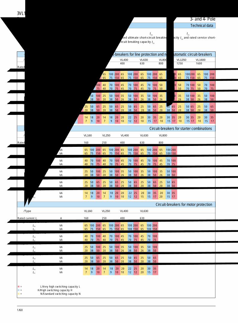
1/60
3VL160X~VL1600断路器 3VL160X to VL1600 Circuit-Breakers3 极和 4 极 3- and 4- Pole技术数据 Technical data
额定短路分断能力Rated short-circuit breaking capacity
型号 /Type VL160X VL160 VL250 VL400 VL630 VL800 VL1250 VL1600额定电流 A 160 160 250 400 630 800 1250 1600Rated current In
至 /up to 220/240 V ACIcu kA 65 100 65 100 200 65 100 200 65 100 200 65 100 200 65 100 200 65 100200 65 100 200Ics kA 65 75 65 75 150 65 75 150 65 75 150 65 75 150 65 100 150 65 75 150 65 75 150
至 /up to 380/415 V ACIcu kA 40 70 40 70 100 40 70 100 45 70 100 45 70 100 50 70 100 50 70 100 50 70 100Ics kA 40 70 40 70 75 40 70 75 45 70 75 45 70 75 50 70 75 50 70 75 50 70 75
至 /up to 440 V ACIcu kA 25 42 25 50 100 25 50 100 35 50 100 35 50 100 35 50 100 35 50 100 35 50 100Ics kA 20 32 20 38 50 20 38 50 26 38 50 26 38 50 26 38 50 26 38 50 26 38 50
至 /up to 500 V ACIcu kA 18 42 25 50 65 25 50 65 25 50 65 25 50 65 25 50 65 25 50 65 25 50 65Ics kA 14 32 20 38 50 20 38 50 20 38 50 20 38 50 20 38 50 20 38 50 20 38 50
至 /up to 690 V ACIcu kA 8 12 14 18 20 14 18 20 20 22 25 20 30 35 20 30 35 20 30 35 20 30 35Ics kA 4 6 7 9 10 7 9 10 10 12 12 10 15 17 10 15 17 10 15 17 10 15 17
型号 /Type VL160 VL250 VL400 VL630 VL800额定电流Rated current In A 160 250 400 630 800至 /up to 220/240 V AC
Icu kA 65 100 200 65 100 200 65 100 200 65 100 200 65 100200Ics kA 65 75 150 65 75 150 65 75 150 65 75 150 65 100150
至 /up to 380/415 V ACIcu kA 40 70 100 40 70 100 45 70 100 45 70 100 45 70 100Ics kA 40 70 75 40 70 75 45 70 75 45 70 75 45 70 75
至 /up to 440 V ACIcu kA 25 50 100 25 50 100 35 50 100 35 50 100 35 50 100Ics kA 20 38 50 20 38 50 26 38 50 26 38 50 26 38 50
至 /up to 500 V ACIcu kA 25 50 65 25 50 65 25 50 65 25 50 65 25 50 65Ics kA 20 38 50 20 38 50 20 38 50 20 38 50 20 38 50
至 /up to 690 V ACIcu kA 14 18 20 14 18 20 20 22 25 20 30 35 20 30 35Ics kA 7 9 10 7 9 10 10 12 12 15 15 17 20 15 17
型号 /Type VL160 VL250 VL400 VL630额定电流Rated current In A 160 250 400 630至 /up to 220/240 V AC
Icu kA 65 100 200 65 100 200 65 100 200 65 100 200Ics kA 65 75 150 65 75 150 65 100 150 65 100 150
至 /up to 380/415 V ACIcu kA 40 70 100 40 70 100 45 70 100 45 70 100Ics kA 40 70 75 40 70 75 45 70 75 45 70 75
至 /up to 440 V ACIcu kA 25 50 100 25 50 100 35 50 100 35 50 100Ics kA 20 38 50 20 38 50 26 38 50 26 38 50
至 /up to 500 V ACIcu kA 25 50 65 25 50 65 25 50 65 25 50 65Ics kA 20 38 50 20 38 50 20 38 50 20 38 50
至 /up to 690 V ACIcu kA 14 18 20 14 18 20 20 22 25 20 30 35Ics kA 7 9 10 7 9 10 10 12 12 20 15 17
� = 极高分断能力 L/Very high switching capacity L� = 高分断能力 H/High switching capacity H� = 标准分断能力 N/Standard switching capacity N
线路保护用断路器和隔离开关 Circuit-breakers for line protection and non-automatic circuit-breakers
起动器组合用断路器 Circuit-breakers for starter combinations
电动机保护用断路器 Circuit-breakers for motor protection
额定极限短路分断能力 Icu 和额定运行短路分断能力 Ics
Rated ultimate short-circuit breaking capacity Icu and rated service short-circuit breaking capacity Ics
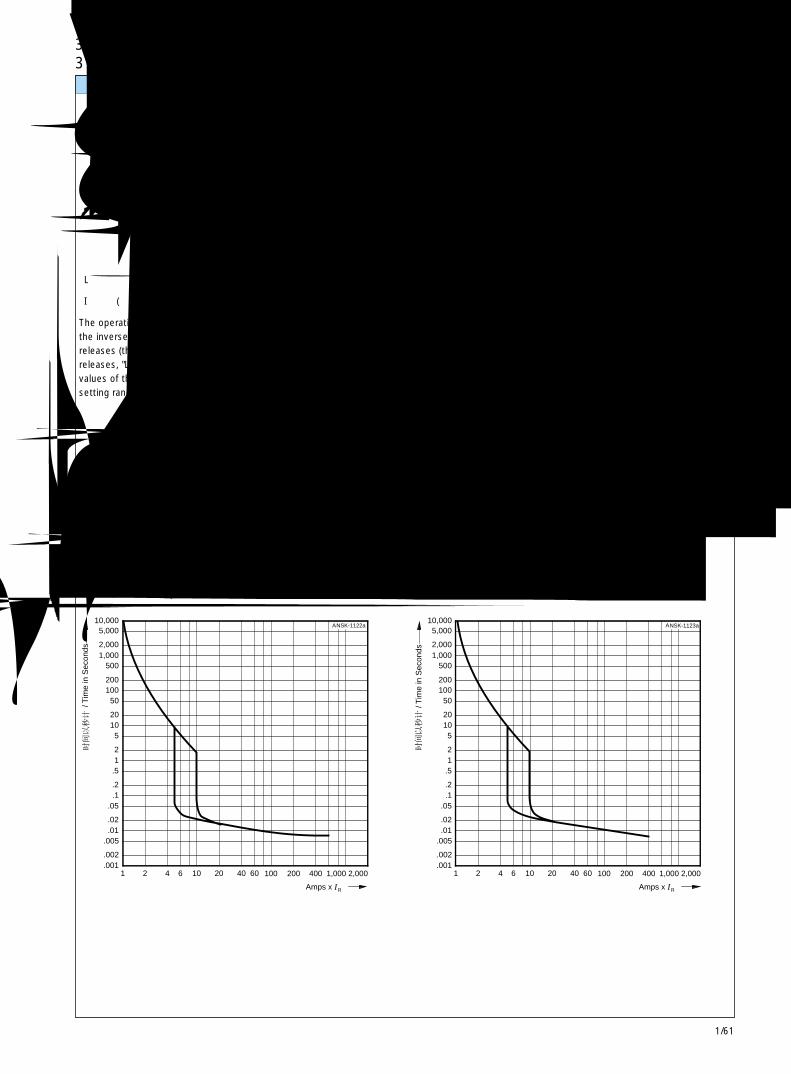
1/61
3VL160X ~ VL1600断路器 3VL160X to VL1600 Circuit-Breakers3 极和 4 极 3- and 4-pole 1
1
20
.5
.1.05
.01
.02
.0011
.2
.002
.005
42 106 40 60 100 200 400 1,000 2,000
500
2,000
5,000
1,000
10,000
200100
1020
50
2
5
NSK-1121a
Amps x IR
A
/ Tim
e in
Sec
onds
1
20
.5
.1.05
.01
.02
.0011
.2
.002
.005
42 106 40 60 100 200 400 1,000 2,000
500
2,000
5,000
1,000
10,000
200100
1020
50
2
5
Amps x IR
NSK-1122aA
/ Tim
e in
Sec
onds
1
20
.5
.1.05
.01
.02
.0011
.2
.002
.005
42 106 40 60 100 200 400 1,000 2,000
500
2,000
5,000
1,000
10,000
200100
1020
50
2
5
NSK-1123a
Amps x IR
A
/ Tim
e in
Sec
onds
脱扣特性 Tripping characteristics
反时限过电流脱扣器(热过载脱扣器,“L”脱扣器)所标定的动作值是在冷态下和在导电回路具有衡定的电流负载时,所有整定范围的误差带的平均值。
瞬时(电磁式)短路脱扣器(“I”脱扣器)的脱扣特性是以额定相电流 In为基础的,对于带可调热过载脱扣器的断路器,指整定范围的最大额定电流。对于较低的整定电流值,“I”脱扣器的动作电流倍数会相应增加。
“L”热过载脱扣器
“I”瞬时(电磁式)短路脱扣器
The operating values specified forthe inverse time overcurrentreleases (thermal overloadreleases, "L" releases) are meanvalues of the scatter bands of allsetting ranges from the cold state
3VL160X 断路器在 415V 时,线路保护用断路器的脱扣特性,“I”脱扣器为固定式
3VL160X circuit-breakerTripping characteristics of circuit-breakers for line protection,at 415 V; "I" release fixed setting
3VL250 断路器在 415V 时,线路保护用断路器的脱扣特性,“I”脱扣器可调
3VL250 circuit-breakerTripping characteristics of circuit-breakers for line protection,at 415 V; "I" release adjustable
3VL160 断路器在 415V 时,线路保护用断路器的脱扣特性,“I”脱扣器可调
3VL160 circuit-breakerTripping characteristics of circuit-breakers for line protection,at 415 V; "I" release adjustable
and with uniform current loadingof the conducting paths.
The tripping characteristics of theinstantaneous (electromagnetic)short-circuit releases ("I" releases)are based on the rated phasecurrent In , which in the case ofcircuit-breakers with adjustablethermal overload releases is alsothe upper value of the settingrange. With a lower settingcurrent, a correspondingly highermultiple is obtained for theoperating current of the "I"release.
"L" thermal overload release
"I" instantaneous (electromag-netic) short-circuit release.
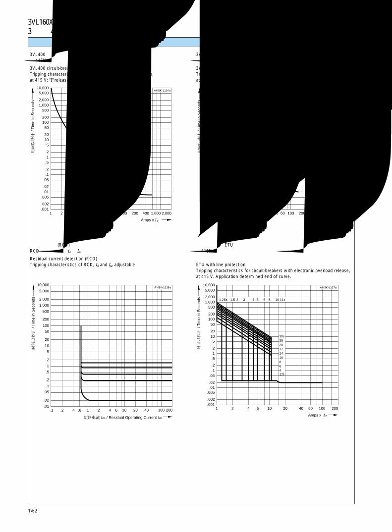
1/62
3VL160X ~ VL1600断路器 3VL160X to VL1600 Circuit-Breakers3 极和 4 极 3- and 4-pole脱扣特性 Tripping characteristics
1
20
.5
.1.05
.01
.02
.0011
.2
.002
.005
42 106 40 60 100 200 400 1,000 2,000
500
2,000
5,000
1,000
10,000
200100
1020
50
2
5
NSK-1124a
Amps x IR
A
/ Tim
e in
Sec
onds
1
20
.5
.1.05
.01
.02
.0011
.2
.002
.005
42 106 40 60 100 200 400 1,000 2,000
500
2,000
5,000
1,000
10,000
200100
1020
50
2
5
NSK-1125a
Amps x IR
A
/ Tim
e in
Sec
onds
10
2
5
1
.5
.1
.2
.01.1
2
.02
.05
.4.2 1.6 4 6 10 20 40 200
5,000
10,000
2,000
1,000
100
200
500
20
50
NSK-1126a
100
A
I∆n
/ Tim
e in
Sec
onds
/ Residual Operating Current I∆n
1
20
.5
.1.05
.01
.02
.0011
.2
.002
.005
42 106 40 60 100 200
500
10,000
200100
1020
50
2
5
NSK-1127a
1,0002,000
5,000
1,25x 1,5 2 3 4 5 6 8 10 11x
30s25201714108642,5
Amps x I
A
R
/ Tim
e in
Sec
onds
3VL400 断路器在 415V 时,线路保护用断路器的脱扣特性,“I”脱扣器可调
3VL400 circuit-breakerTripping characteristics of circuit-breakers for line protection,at 415 V; "I" release adjustable
剩余电流检测(RCD)RCD的脱扣特性,td 和 I∆n 可调
Residual current detection (RCD)Tripping characteristics of RCD, td and I∆n adjustable
3VL630 断路器在 415V 时,线路保护用断路器的脱扣特性,“I”脱扣器可调
3VL630 circuit-breakerTripping characteristics of circuit-breakers for line protection,at 415 V; "I" release adjustable
带线路保护的 ETU在415V时,带电子式过载脱扣器的断路器的脱扣特性,实际故障情况决定曲线末端的状态
ETU with line protectionTripping characteristics for circuit-breakers with electronic overload release,at 415 V. Application determined end of curve.
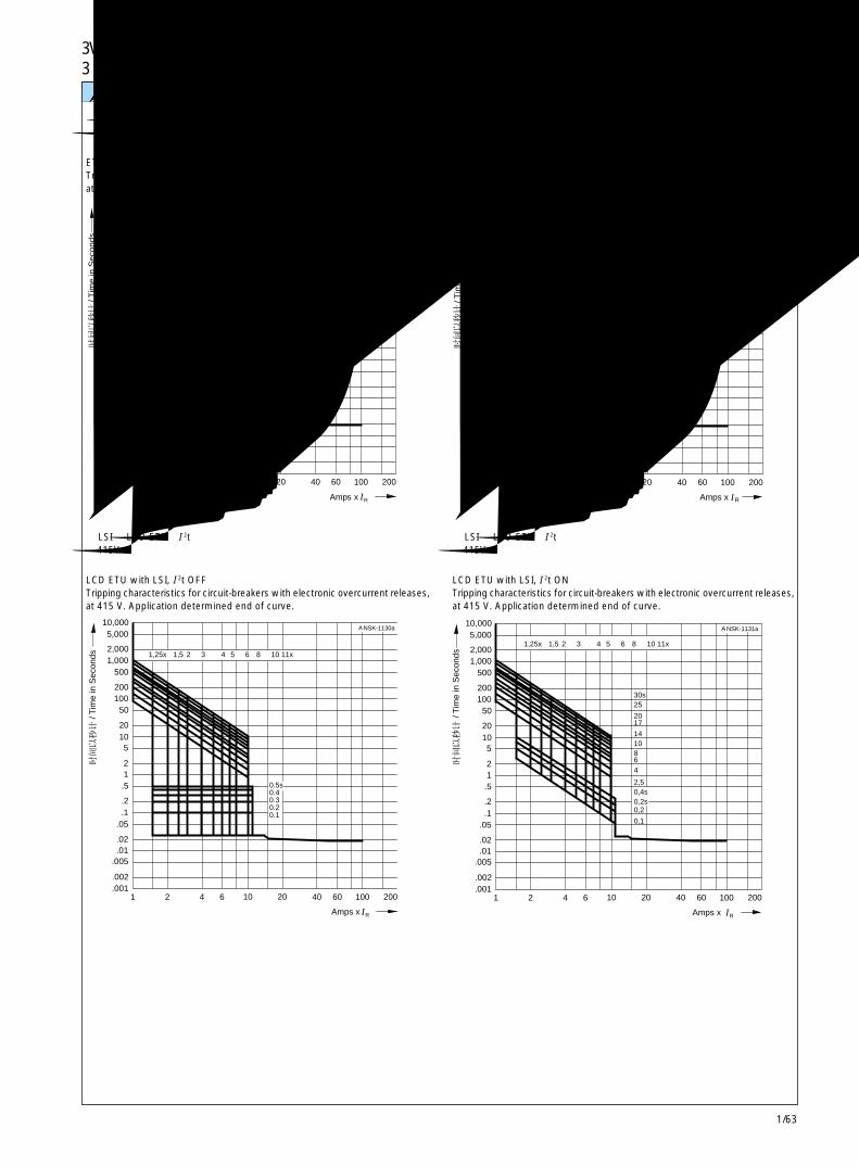
1/63
3VL160X ~ VL1600断路器 3VL160X to VL1600 Circuit-Breakers3 极和 4 极 3- and 4-pole 1
1
20
.5
.1.05
.01
.02
.0011
.2
.002
.005
42 106 40 60 100 200
500
10,000
200100
1020
50
2
5
NSK-1128a
1,0002,000
5,000
1,25x 1,5 2 3 4 5 6 8 10 11x
0.5s0.40.30.20.1
Amps x IR
A
/ Tim
e in
Sec
onds
1
20
.5
.1.05
.01
.02
.0011
.2
.002
.005
42 106 40 60 100 200
500
10,000
200100
1020
50
2
5
NSK-1129a
1,0002,000
5,000
1,25x 1,5 2 3 4 5 6 8 10 11x
0.4s0.30.20.1
Amps x IR
A
/ Tim
e in
Sec
onds
1
20
.5
.1.05
.01
.02
.0011
.2
.002
.005
42 106 40 60 100 200
500
10,000
200100
1020
50
2
5
NSK-1130a
1,0002,000
5,000
1,25x 1,5 2 3 4 5 6 8 10 11x
0.5s0.40.30.20.1
Amps x IR
A
/ Tim
e in
Sec
onds
1
20
.5
.1.05
.01
.02
.0011
.2
.002
.005
42 106 40 60 100 200
500
10,000
200100
1020
50
2
5
NSK-1131a
1,0002,000
5,0001,25x 1,5 2 3 4 5 6 8 10 11x
30s25
2017
1410864
2,50,4s0,2s0,2
0,1
Amps x IR
A
/ Tim
e in
Sec
onds
脱扣特性 Tripping characteristics
带 LSI 的 ETU,I 2t 关闭在415V时,带电子式过载脱扣器的断路器的脱扣特性,实际故障情况决定曲线末端的状态
ETU with LSI, I 2t OFFTripping characteristics for circuit-breakers with electronic overcurrent releases,at 415 V. Application determined end of curve.
带 LSI 的 LCD ETU,I 2t 关闭在415V时,带电子式过载脱扣器的断路器的脱扣特性。实际故障情况决定曲线末端的状态
LCD ETU with LSI, I 2t OFFTripping characteristics for circuit-breakers with electronic overcurrent releases,at 415 V. Application determined end of curve.
带 LSI 的 ETU,I 2t 开启在415V时,带电子式过载脱扣器的断路器的脱扣特性。实际故障情况决定曲线末端的状态
ETU with LSI, I 2t ONTripping characteristics for circuit-breakers with electronic overcurrent releases,at 415 V. Application determined end of curve.
带 LSI 的 LCD ETU,I 2t 开启在415V时,带电子式过载脱扣器的断路器的脱扣特性。实际故障情况决定曲线末端的状态
LCD ETU with LSI, I 2t ONTripping characteristics for circuit-breakers with electronic overcurrent releases,at 415 V. Application determined end of curve.

1/64
3VL160X ~ VL1600断路器 3VL160X to VL1600 Circuit-Breakers3 极和 4 极 3- and 4-pole
1
20
.5
.1.05
.01
.02
.0011
.2
.002
.005
42 106 40 60 100 200 400 1,000 2,000
500
2,000
5,000
1,000
10,000
200100
1020
50
2
5
Amps x In
NSK-1132
0.5s0.40.30.20.1
ETU at 4s
/ Tim
e in
Sec
onds
1
20
.5
.1.05
.01
.02
.0011
.2
.002
.005
42 106 40 60 100 200 400 1,000 2,000
500
2,000
5,000
1,000
10,000
200100
1020
50
2
5
NSK-1133a
0.4s0.30.20.1
Amps x I
A
n
/ Tim
e in
Sec
onds
1
23
13
0 1 5 10mint
NS
1-50
01b
A
Cooling down
Heating upWarm
Cold
Warm
Cold
/ Bre
ak-t
ime
脱扣特性 Tripping characteristics
带接地故障保护的 LCD ETU 和 ETU (仅为 td = 400ms),I 2t 关闭在 415V 时,带电子式过载脱扣器的断路器的脱扣特性。
LCD ETU and ETU (td = 400 ms only) with earth fault protection, I 2t OFFTripping characteristics for circuit-breakers with electronic overcurrent releases,at 415 V
带接地故障保护的 LCD ETU,I 2t 开启在 415V 时,带电子式过载脱扣器的断路器的脱扣特性。
LCD ETU with earth fault protection, I 2t ONTripping characteristics for circuit-breakers with electronic overcurrent releases,at 415 V
带电子式过电流脱扣器的电动机 /发电机保护用 3VL160,VL250,VL400 和 VL630 断路器的特性。
过电流反时限脱扣器的脱扣时间仅对非预负载(冷态)起动状态有效。在工作温度时(在加载额定电流之后),脱扣时间缩短至约33%。在过电流脱扣之后,脱扣时间按照脱扣时间特性缩短(见右图),这样,在重新起动电动机之前,需要冷却几分钟。
脱扣时间特性(热记忆)
Tripping time characteristics (thermal memory)
Characteristics of 3VL160, VL250,VL400 and VL630 circuit-breakersfor motor/generator protectionwith electronic overcurrentreleases.
The tripping times of the in-verse-time delayed overcurrentreleases are only valid for thenonpreloaded (cold) start state. Atoperating temperature (after loadwith rated current), the trippingtimes are reduced to approx.33%. After an overcurrent trip,the tripping times are reducedaccording to the tripping timecharacteristics (see fig. on theright) so that cooling down forsome minutes is required beforerestart ing the motor. 分
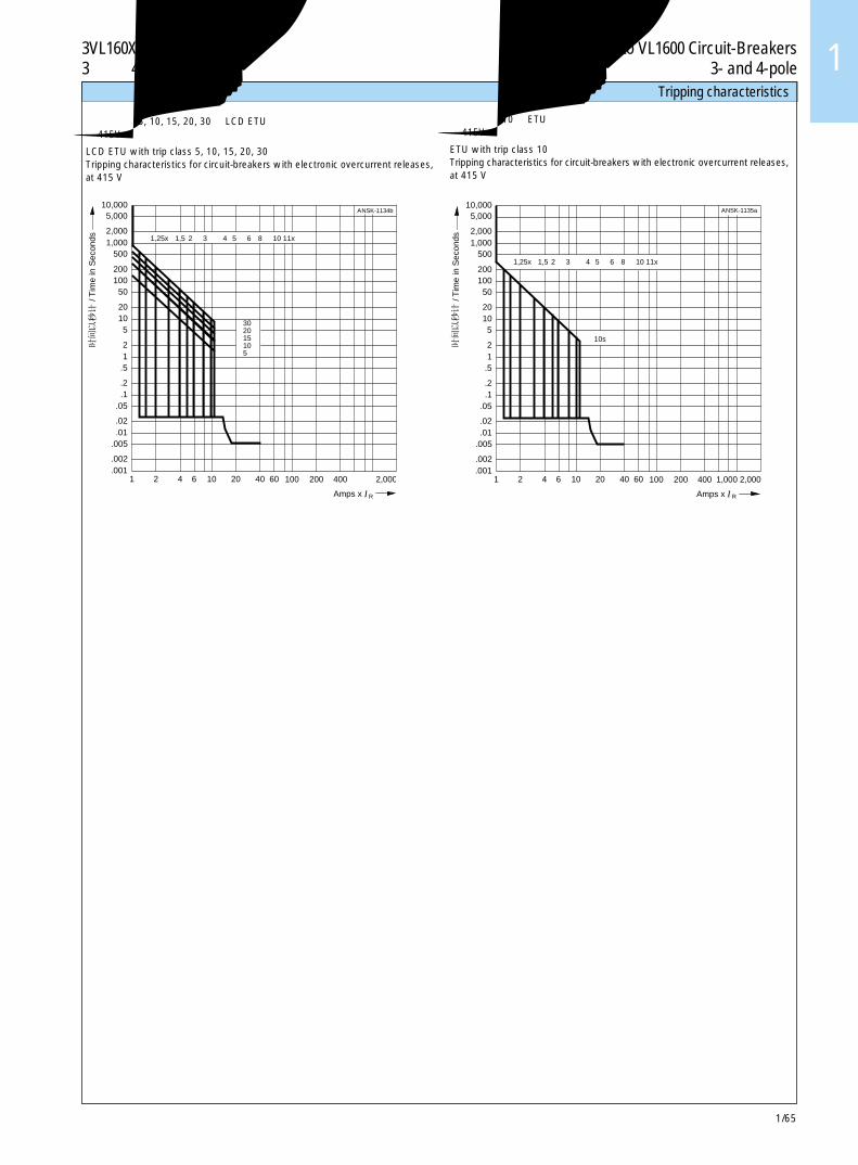
1/65
3VL160X ~ VL1600断路器 3VL160X to VL1600 Circuit-Breakers3 极和 4 极 3- and 4-pole 1
1
20
.5
.1.05
.01
.02
.0011
.2
.002
.005
42 106 40 60 100 200 400 2,000
500
2,000
5,000
1,000
10,000
200100
1020
50
2
5
NSK-1134b
1,25x 1,5 2 3 4 5 6 8 10 11x
302015105
Amps x I
A
R
/ Tim
e in
Sec
onds
1
20
.5
.1.05
.01
.02
.0011
.2
.002
.005
42 106 40 60 100 200 400 1,000 2,000
500
2,000
5,000
1,000
10,000
200100
1020
50
2
5
NSK-1135a
1,25x 1,5 2 3 4 5 6 8 10 11x
10s
Amps x I
A
R
/ Tim
e in
Sec
onds
时滞等级为 5, 10, 15, 20, 30的 LCD ETU在 415V 时,带电子式过载脱扣器的断路器的脱扣特性。
LCD ETU with trip class 5, 10, 15, 20, 30Tripping characteristics for circuit-breakers with electronic overcurrent releases,at 415 V
时滞等级为 10 的 ETU在 415V 时,带电子式过载脱扣器的断路器的脱扣特性。
ETU with trip class 10Tripping characteristics for circuit-breakers with electronic overcurrent releases,at 415 V
脱扣特性 Tripping characteristics
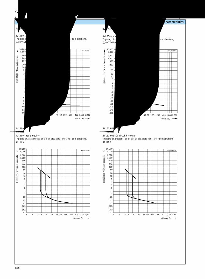
1/66
3VL160X ~ VL1600断路器 3VL160X to VL1600 Circuit-Breakers3 极和 4 极 3- and 4-pole
1
20
.5
.1.05
.01
.02
.0011
.2
.002
.005
42 106 40 60 100 200 400 1,000 2,000
500
2,000
5,000
1,000
10,000
200100
1020
50
2
5
NSK-1136a
Amps x I
A
R
/ Tim
e in
Sec
onds
1
20
.5
.1.05
.01
.02
.0011
.2
.002
.005
42 106 40 60 100 200 400 1,000 2,000
500
2,000
5,000
1,000
10,000
200100
1020
50
2
5
NSK-1137a
Amps x I
A
R
/ Tim
e in
Sec
onds
1
20
.5
.1.05
.01
.02
.0011
.2
.002
.005
42 106 40 60 100 200 400 1,000 2,000
500
2,000
5,000
1,000
10,000
200100
1020
50
2
5
NSK-1138a
Amps x I
A
R
/ Tim
e in
Sec
onds
1
20
.5
.1.05
.01
.02
.0011
.2
.002
.005
42 106 40 60 100 200 400 1,000 2,000
500
2,000
5,000
1,000
10,000
200100
1020
50
2
5
NSK-1139a
Amps x I
A
R
/ Tim
e in
Sec
onds
脱扣特性 Tripping characteristics
3VL160 断路器起动器组合用断路器的脱扣特性, Icu 40/70/100kA
3VL160 circuit-breakerTripping characteristics of circuit-breakers for starter combinations,Icu 40/70/100 kA
3VL400 断路器415V 时,起动器组合用断路器的脱扣特性。
3VL400 circuit-breakerTripping characteristics of circuit-breakers for starter combinations,at 415 V
3VL250 断路器起动器组合用断路器的脱扣特性,Icu 40/70/100kA
3VL250 circuit-breakerTripping characteristics of circuit-breakers for starter combinations,Icu 40/70/100 kA
3VL630/VL800 断路器在415V时, 起动器组合用断路器的脱扣特性。
3VL630/VL800 circuit-breakersTripping characteristics of circuit-breakers for starter combinations,at 415 V
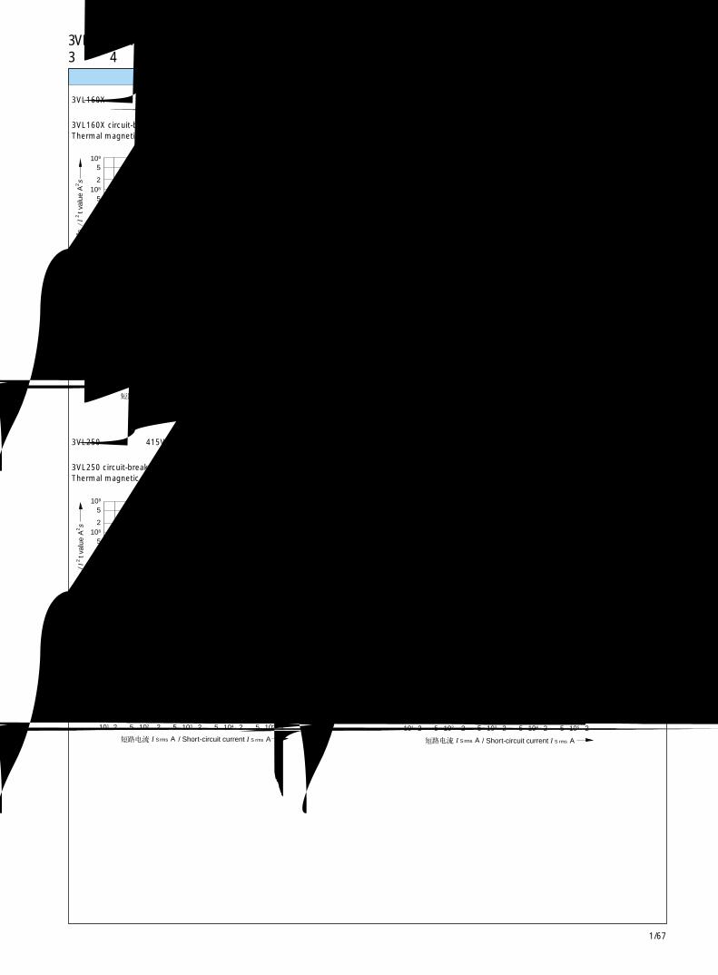
1/67
3VL160X ~ VL1600断路器 3VL160X to VL1600 Circuit-Breakers3 极和 4 极 3- and 4-pole 1
NSK-1140a
160A
63A
16A 160A
16A
105
5
104
5
103
2
102
2
2
5
5
2
5
108
109
2107
106
2
5
2
5
5101 52 2102 103 2 5 104 2 5 105 2
A
A
I S rms
/ I 2
t val
ue A
2 s
/ Short-circuit current I S rms A
105
5
5
104
5
103
2
102
101
2
2
5
52 2102 103 2
5
2
5
108
109
2107
106
2
5
2
5
5 104 2 5 105 2
NSK-1141a
160A
50A
A
/ I 2
t val
ue A
2 s
AI S rms / Short-circuit current I S rms A
105
5
104
5
103
2
102
2
2
5
5
2
5
108
109
2107
106
2
5
2
5
NSK-1142a
5101 52 2102 103 2 5 104 2 5 105 2
250A
125A
A
/ I 2
t val
ue A
2 s
AI S rms / Short-circuit current I S rms A
106
5
105
5
104
2
103
2
2
5
5
2
5
109
1010
2108
107
2
5
2
5
NSK-1143a
5101 52 2102 103 2 5 104 2 5 105 2
400A
200A
A
/ I 2
t val
ue A
2 s
AI S rms / Short-circuit current I S rms A
允通量曲线 Let-through curves
3VL160X 断路器,在 415V 时为 16A~160A热磁式过电流脱扣器
3VL160X circuit-breaker, 16 A to 160 A at 415 VThermal magnetic overcurrent releases
3VL250 断路器,在 415V 时 125A~250A热磁式过电流脱扣器
3VL250 circuit-breaker, 125 A to 250 A at 415 VThermal magnetic overcurrent releases
3VL160 断路器,在 415V 时 50A~160A热磁式过电流脱扣器
3VL160 circuit-breaker, 50 A to 160 A at 415 VThermal magnetic overcurrent releases
3VL400 断路器,在 415V 时,200A~400A热磁式过电流脱扣器
3VL400 circuit-breaker, 200 A to 400 A at 415 VThermal magnetic overcurrent releases
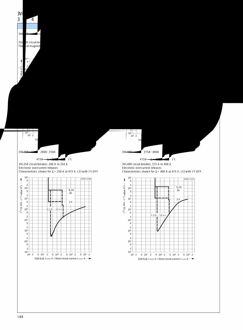
1/68
3VL160X ~ VL1600断路器 3VL160X to VL1600 Circuit-Breakers3 极和 4 极 3- and 4-pole
105
5
104
5
103
2
102
2
2
5
5
2
5
108
109
2107
106
2
5
2
5
NSK-1145a
5101 52 2102 103 2 5 104 2 5 105 2
TR (s)30
2.5
L 1.5 ... 11 x I
A
/ I 2
t val
ue A
2 s
AI S rms / Short-circuit current I S rms A
105
5
104
5
103
2
102
2
2
5
5
2
5
108
109
2107
106
2
5
2
5
NSK-1146a
5101 52 2102 103 2 5 104 2 5 105 2
TR (s)30
2.5
L 1.5 ... 11 x I
A
/ I 2
t val
ue A
2 s
AI S rms / Short-circuit current I S rms A
105
5
104
5
103
2
102
2
2
5
5
2
5
108
109
2107
106
2
5
2
5
NSK-1147a
5101 52 2102 103 2 5 104 2 5 105 2
TR (s)30
2.5
L 1.5 ... 11 x I
A
/ I 2
t val
ue A
2 s
AI S rms / Short-circuit current I S rms A
106
5
105
5
104
2
103
2
2
5
5
2
5
109
1010
2108
107
2
5
2
5
NSK-1144a
5101 52 2102 103 2 5 104 2 5 105 2
630A
315A
A
/ I 2
t val
ue A
2 s
AI S rms / Short-circuit current I S rms A
允通量曲线 Let-through curves
3VL630 断路器,在 415V 时,315A~630A热磁式过电流脱扣器
3VL630 circuit-breaker, 315 A to 630 A at 415 VThermal magnetic overcurrent releases
3VL250 断路器,200A~250A电子式过电流脱扣器所示特性为在 415V 时 IR =250A,LSI,I 2t 关闭
3VL250 circuit-breaker, 200 A to 250 AElectronic overcurrent releasesCharacteristics shown for IR = 250 A at 415 V, LSI with I 2t OFF
3VL160 断路器,63A~160A电子式过电流脱扣器所示特性为在 415V 时 IR = 160A,LSI,I 2t 关闭
3VL160 circuit-breaker, 63 A to 160 AElectronic overcurrent releasesCharacteristics shown for Ir = 160 A at 415 V, LSI with I 2t OFF
3VL400 断路器,315A~400A电子式过电流脱扣器所示特性为在 415V 时 IR = 400A,LSI,I 2t 关闭
3VL400 circuit-breaker, 315 A to 400 AElectronic overcurrent releasesCharacteristics shown for IR = 400 A at 415 V, LSI with I 2t OFF
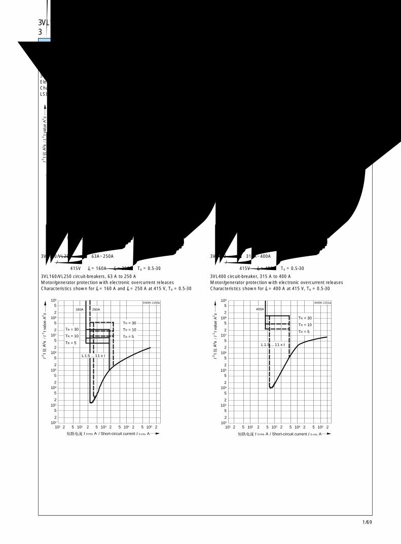
1/69
3VL160X ~ VL1600断路器 3VL160X to VL1600 Circuit-Breakers3 极和 4 极 3- and 4-pole 1
107
5
106
5
105
2
104
2
2
5
5
2
5
1010
1011
2109
108
2
5
2
5
NSK-1149a
5102 52 2103 104 2 5 105 2 5 106 2
1250A
1600A
TR (s)30
2.5
L 1.5 ... 11 x I
A
/ I 2
t val
ue A
2 s
AI S rms / Short-circuit current I S rms A
107
5
106
5
105
2
104
2
2
5
5
2
5
1010
1011
2109
108
2
5
2
5
NSK-1148a
5102 52 2103 104 2 5 105 2 5 106 2
630A 800A
TR (s)30
2.5
L 1.5 ... 11 x I
A
/ I 2
t val
ue A
2 s
AI S rms / Short-circuit current I S rms A
105
5
104
5
103
2
102
2
2
5
5
2
5
108
109
2107
106
2
5
2
5
NSK-1150a
5101 52 2102 103 2 5 104 2 5 105 2
160A 250A
TR = 30
L 1.5 ... 11 x I
TR = 10
TR = 5
TR = 30
TR = 10
TR = 5
A
/ I 2
t val
ue A
2 s
AI S rms / Short-circuit current I S rms A
105
5
104
5
103
2
102
2
2
5
5
2
5
108
109
2107
106
2
5
2
5
NSK-1151a
5101 52 2102 103 2 5 104 2 5 105 2
400A
TR = 30
L 1.5 ... 11 x I
TR = 10
TR = 5
A
/ I 2
t val
ue A
2 s
AI S rms / Short-circuit current I S rms A
穿越电流波形 Let-through curves
3VL630/VL800 断路器,630A~800A电子式过电流脱扣器所示特性为在 415V 时 IR = 630A 和 IR = 800A,LSI,I 2t 关闭
3VL630/VL800 circuit-breakers, 630 A to 800 AElectronic overcurrent releasesCharacteristics shown for IR = 630 A and IR = 800 A at 415 V,LSI with I 2t OFF
3VL160/VL250 断路器,63A~250A电动机 / 发电机保护,带电子式过电流脱扣器所示特性为在 415V 时 IR = 160A 和 IR = 250A,TR = 0.5-30
3VL160/VL250 circuit-breakers, 63 A to 250 AMotor/generator protection with electronic overcurrent releasesCharacteristics shown for IR = 160 A and IR = 250 A at 415 V, TR = 0.5-30
3VL1250/VL1600 断路器,1000A~1600A电子式过电流脱扣器所示特性为在 415V 时 IR = 1250A 和 IR = 1600A,LSI,I 2t 关闭
3VL1250/VL1600 circuit-breakers, 1000 A to 1600 AElectronic overcurrent releasesCharacteristics shown for IR= 1250 A and IR = 1600 A at 415 V,LSI with I 2t OFF
3VL400 断路器,315A~400A电动机 / 发电机保护,带电子式过电流脱扣器所示特性为在 415V 时 IR = 400A,TR = 0.5-30
3VL400 circuit-breaker, 315 A to 400 AMotor/generator protection with electronic overcurrent releasesCharacteristics shown for IR = 400 A at 415 V, TR = 0.5-30

1/70
3VL160X ~ VL1600断路器 3VL160X to VL1600 Circuit-Breakers3 极和 4 极 3- and 4-pole
7
1EMS
EBS
3
8
2
9
10
5
12
6
11
4L
K
86
F3 F2
AS
HS
3
4
75
1
2
T1
T3
T4
K
4
T2
NL
2
K
L
Q1
3N 1
6
L
K
14
15
A1
F1
-
+
L
5
NSE00760aNSK-1106a
D1
D2C2
C1
>>
>>
U<
I
I
S
I
7
EBS
EMS
8
3
4
11
6
12
5
10
9
2
1
K
L
4
5
6
7
8
AS
2N
K
L
K
LT4
T1
T2
T3
6
K
L
3
D1
D2
F2
2
1
F3
C2
C1
4
3
HS
Q1
F1
1N
-
+
14
15
5
A1
S
I
L
>>
>>
NSE00759aNSK-1105a
K1
U<
I
I
3
4
C1
C2U<
D1
D2
EBS
EMS5
12
1
3
8
7
2 6
9 11
4
10
N 1
N 2
AS7
8
5
6
5
6
HS
42
31
NSE00758aNSK-1104b
>I >I >I >I
电路图 Circuit diagrams
下列图中使用的符号表示开关设备的型号、线路和工作方式,符合DIN40 713标准,但不表示其实际设计。
此处所示的可能组合数量并非全部。对于未示出的类型,应相应修改或补充电路图。
此处仅显示必要的电路图,以便更好地了解有关设备的工作方式。
The symbols used in thefollowing diagrams indicate thetype, circuitry and mode ofoperation of the switching
devices in accordance with DIN40 713, but not their actualdesign.
The number of possible combina-tions shown here is notcomplete. For versions differentfrom those shown, the dia-grams
should be modified or supple-mented accordingly.
Circuit diagrams are shown onlywhere they are necessary forbetter understanding of the modeof operation of the equip-mentconcerned.
带热磁式过电流脱扣器的线路保护用3VL160X~VL630 3极和4极断路器的端子图
Terminal diagram for 3VL160X to VL630, 3- and 4-pole circuit-breakersfor line protection with thermal magnetic overcurrent releases
旋转驱动操作机构超前动作辅助开关Rotary Drive OperatorLeading auxiliary switch
报警开关Alarm switch
Q1 主触头A1 电子式过电流脱扣器F1 A1 用脱扣器电磁线圈F2 欠压脱扣器F3 分励脱扣器HS 辅助开关AS 报警开关EBS 超前动作辅助开关,合闸 - 分闸
(包含在旋转驱动机构中)EMS 超前动作辅助开关,分闸 - 合闸
(包含在旋转驱动机构中)T1...T4 电流互感器
Q1 Main contactsA1 Electronic overcurrent releaseF1 Release solenoid for A1F2 Undervoltage releaseF3 Shunt releaseHS Auxiliary switchesAS Alarm switchesEBS Leading auxiliary switch after ON to OFF
(integrated in the rotary drive)EMS Leading auxiliary switch after OFF to ON
(integrated in the rotary drive)T1 ... T4 Current transformers
带电子式过电流脱扣器的线路和电动机保护用3VL160和VL250 3极和4极断路器的电路图
Circuit diagram for 3VL160 and VL250, 3- and 4-pole circuit-breakersfor line and motor protection with electronic overcurrent releases
电动机保护用 3VL400 断路器以及带电子式过电流脱扣器的线路保护用3VL400~VL1600 3 极和 4 极断路器的电路图
Circuit diagram for 3VL400 circuit-breakers for motor protectionand 3VL400 to VL1600, 3- and 4-pole circuit-breakers for line protectionwith electronic overcurrent releases
辅助开关Auxiliary switch
辅助开关Auxiliary switch
报警开关Alarm switch
旋转驱动操作机构超前动作辅助开关Rotary Drive OperatorLeading auxiliary switch
辅助开关Auxiliary switch
报警开关Alarm switch
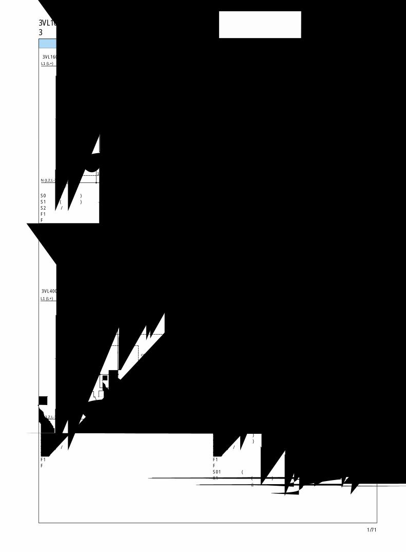
1/71
3VL160X ~ VL1600断路器 3VL160X to VL1600 Circuit-Breakers3 极和 4 极 3- and 4-pole 1
L1 (L+)
N (L2,L-)
K1
S01
1
S2A
S1
S0
K12 3 4
S2B
MPE
7
8
Y1
5
NNSK-1103b
SE-00763a
U<
F
F
OFF/0 ON/1
OFF
ON
S4
N (L2,L-)
S0
L1 (L+)
S1
S2A
2
S2B
3 4
M 5 PE
NSE00762aNSK-1102b
Y1
F
F
ON
OFF
OFF/0 ON/1
1
L1 (L+)
N (L2,L-)
K1
S01
1
S2A
S1
S0
K12 3 4
S2B
MPE
7
8
Y1
5
NNSK-1101b
SE-00591a
U<
F
F
OFF/0 ON/1
OFF
ON
N (L2,L-)
PE
1
M
L1 (L+)
S2A
2 3 4
S2B
5
Y1
NSE00761aNSK-1100a
F
F
ON
OFF
OFF/0 ON/1
电路图
3VL160X~VL250断路器用电动机储能操作机构。不与欠压脱扣器一起使用。
S0 分闸(用户提供)S1 合闸(用户提供)S2 自动 / 手动选择器F1 储能用脱扣器F 控制线路熔断器
3VL400~VL800断路器用电动机储能操作机构。不与欠压脱扣器一起使用。
S0 分闸S1 合闸S2 自动 / 手动选择器S4 铰链“开启”开关F1 储能用脱扣器F 控制线路熔断器
带欠压脱扣器的 3VL160X~VL250 断路器用电动机储能操作机构
S0 分闸(用户提供)S1 合闸(用户提供)S2 自动 / 手动选择F1 储能用脱扣器F 控制线路熔断器S01 远程命令(用户提供)K1 接触器继电器(用户提供)注:可连接一个单独报警开关触头(7-8),便于在“脱扣”后自动储能。
建议不要为已脱扣的断路器提供自动合闸,以避免断路器在未能解除线路故障时合闸。
带欠压脱扣器的 3VL400~VL800 断路器用电动机储能操作机构
S0 分闸(用户提供)S1 合闸(用户提供)S2 自动 / 手动选择S4 铰链“开启”开关F1 储能用脱扣器F 控制线路熔断器S01 远程命令(用户提供)K1 接触器继电器(用户提供)注:可连接一个单独报警开关触头(7-8),便于在“脱扣”后自动储能。
建议不要为已脱扣的断路器提供自动合闸,以避免断路器在未能解除线路故障时合闸。
电动机储能操作机构
现场分闸
锁定
分闸 合闸
自动 /手动
手动分闸 /储能手柄
电动机储能操作机构电动机储能操作机构
分闸 合闸
锁定
分闸 合闸
自动 / 手动
手动分闸 /储能手柄
锁定
分闸 合闸
自动 /手动
手动分闸 /储能手柄
现场分闸
现场分闸
铰链开启开关
铰链开启开关
报警开关
报警开关
电动机储能操作机构
锁定
自动 /手动
手动分闸 /储能手柄
现场分闸
S4
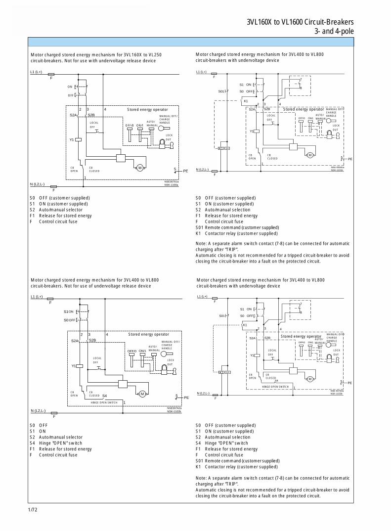
1/72
3VL160X ~ VL1600断路器 3VL160X to VL1600 Circuit-Breakers3 极和 4 极 3- and 4-pole
Motor charged stored energy mechanism for 3VL160X to VL250circuit-breakers. Not for use with undervoltage release device
Motor charged stored energy mechanism for 3VL400 to VL800circuit-breakers with undervoltage device
N (L2,L-)
PE
1
M
L1 (L+)
S2A
2 3 4
S2B
5
Y1
NSE00761aNSK-1100a
F
F
ON
OFF
OFF/0 ON/1
L1 (L+)
N (L2,L-)
K1
S01
1
S2A
S1
S0
K12 3 4
S2B
MPE
7
8
Y1
5
NNSK-1101b
SE-00591a
U<
F
F
OFF/0 ON/1
OFF
ON
L1 (L+)
N (L2,L-)
K1
S01
1
S2A
S1
S0
K12 3 4
S2B
MPE
7
8
Y1
5
NNSK-1103b
SE-00763a
U<
F
F
OFF/0 ON/1
OFF
ON
S4
N (L2,L-)
S0
L1 (L+)
S1
S2A
2
S2B
3 4
M 5 PE
NSE00762aNSK-1102b
Y1
F
F
ON
OFF
OFF/0 ON/1
1
Motor charged stored energy mechanism for 3VL400 to VL800circuit-breakers. Not for use of undervoltage release device
Note: A separate alarm switch contact (7-8) can be connected for automaticcharging after "TRIP".Automatic closing is not recommended for a tripped circuit-breaker to avoidclosing the circuit-breaker into a fault on the protected circuit.
Motor charged stored energy mechanism for 3VL400 to VL800circuit-breakers with undervoltage device
Note: A separate alarm switch contact (7-8) can be connected for automaticcharging after "TRIP".Automatic closing is not recommended for a tripped circuit-breaker to avoidclosing the circuit-breaker into a fault on the protected circuit.
S0 OFF (customer supplied)S1 ON (customer supplied)S2 Auto/manual selectorF1 Release for stored energyF Control circuit fuse
S0 OFF (customer supplied)S1 ON (customer supplied)S2 Auto/manual selectionF1 Release for stored energyF Control circuit fuseS01 Remote command (customer supplied)K1 Contactor relay (customer supplied)
S0 OFF (customer supplied)S1 ON (customer supplied)S2 Auto/manual selectionS4 Hinge "OPEN" switchF1 Release for stored energyF Control circuit fuseS01 Remote command (customer supplied)K1 Contactor relay (customer supplied)
S0 OFFS1 ONS2 Auto/manual selectorS4 Hinge "OPEN" switchF1 Release for stored energyF Control circuit fuse
Stored energy operator
LOCAL
OFF
LOCK
OUT
CB CBOPEN CLOSED
Stored energy operator
Stored energy operatorStored energy operator
LOCAL
OFF
LOCK
OUT
CB CBOPEN CLOSED
AUTO/MANUAL
MANUAL OFF/CHARGEHANDLE
LOCK
OUT
CB CBOPEN CLOSED
AUTO/MANUAL
MANUAL OFF/CHARGEHANDLE
LOCK
OUT
CB CBOPEN CLOSED
AUTO/MANUAL
MANUAL OFF/CHARGEHANDLE
LOCAL
OFFLOCAL
OFF
HINGE OPEN SWITCH
HINGE OPEN SWITCH
AUTO/MANUAL
MANUAL OFF/CHARGEHANDLE
S4

1/73
3VL160X ~ VL1600断路器 3VL160X to VL1600 Circuit-Breakers3 极和 4 极 3- and 4-pole 1
1
2 3 4
N (L2,L-)
F
L1 (L+)
F
M
5
S0
S1
NSK-1095a
PE N (L2,L-)
F
1
L1 (L+)
F
M
2 3 4
8
7
S01
K1
K1
PE5
S0
S1
NSK-1096a
U<
N(L2,L-)
D2
F5
L1(L+)
D1F2
F4
S0
NSK-1097
U<
C2
F5
N(L2,L-)
F4
S0
L1(L+)
S
F3C1
N(L2,L-)NSK-1098
S01
X2
5
6
1
2
3VL
3
4
D2
D1U <
Y2 Y1
22X1
AC 400 V
2221
S02Z1
L2L1
21
NL3
NSK-1099a
不带欠压脱扣器的 3VL1250和 VL1600 断路器用电动机操作机构
S1 合闸(用户提供)S0 分闸(用户提供)F 控制线路中的熔断器
3VL160X~VL1600 断路器用欠压脱扣器和分励脱扣器
触头 S 已包含在分励脱扣器中
带欠压脱扣器的 3VL1250 和 VL1600 断路器用电动机操作机构
S1 合闸(用户提供)S0 分闸(用户提供)F 控制线路中的熔断器S01 远程命令K1 接触器继电器
注:可连接一个单独报警开关触头(7-8),便于在“脱扣”后自动储能。建议不要为已脱扣的断路器提供自动合闸,以避免断路器在未解除线路故障时合闸。
3VL160X~VL1600 断路器用欠压脱扣器延时装置
S01 延时脱扣器S02 急停回路用瞬时脱扣器 (如需要)
延时装置 3TX4
电动机操作机构
铰链断开 锁定
模块合闸 模块分闸
现场合闸 现场分闸
断路器分闸 断路器合闸 锁定
电动机操作机构
铰链断开 锁定
模块合闸 模块分闸
现场合闸 现场分闸
断路器分闸 断路器合闸 锁定
报警开关
“S”已包含在分励脱扣器中
欠压脱扣器 分励脱扣器S0 OFF
电路图
ON
OFF
ON
OFF
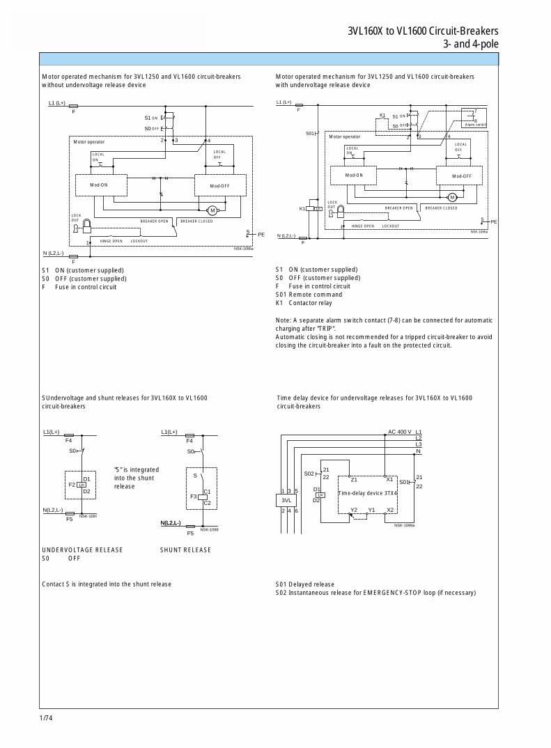
1/74
3VL160X ~ VL1600断路器 3VL160X to VL1600 Circuit-Breakers3 极和 4 极 3- and 4-pole
1
2 3 4
N (L2,L-)
F
L1 (L+)
F
M
5
S0
S1
NSK-1095a
PE N (L2,L-)
F
1
L1 (L+)
F
M
2 3 4
8
7
S01
K1
K1
PE5
S0
S1
NSK-1096a
U<
N(L2,L-)
D2
F5
L1(L+)
D1F2
F4
S0
NSK-1097
U<
C2
F5
N(L2,L-)
F4
S0
L1(L+)
S
F3C1
N(L2,L-)NSK-1098
S01
X2
5
6
1
2
3VL
3
4
D2
D1U <
Y2 Y1
22X1
AC 400 V
2221
S02Z1
L2L1
21
NL3
NSK-1099a
Motor operated mechanism for 3VL1250 and VL1600 circuit-breakerswithout undervoltage release device
SUndervoltage and shunt releases for 3VL160X to VL1600circuit-breakers
Contact S is integrated into the shunt release
Motor operated mechanism for 3VL1250 and VL1600 circuit-breakerswith undervoltage release device
Note: A separate alarm switch contact (7-8) can be connected for automaticcharging after "TRIP".Automatic closing is not recommended for a tripped circuit-breaker to avoidclosing the circuit-breaker into a fault on the protected circuit.
Time delay device for undervoltage releases for 3VL160X to VL1600circuit-breakers
S01 Delayed releaseS02 Instantaneous release for EMERGENCY-STOP loop (if necessary)
Time-delay device 3TX4
Motor operator
LOCAL
ON
LOCAL
OFF
BREAKER OPEN BREAKER CLOSED
LOCKOUT
Mod-ON Mod-OFF
Alarm switch
"S" is integratedinto the shuntrelease
UNDERVOLTAGE RELEASE SHUNT RELEASES0 OFF
S1 ON (customer supplied)S0 OFF (customer supplied)F Fuse in control circuitS01 Remote commandK1 Contactor relay
S1 ON (customer supplied)S0 OFF (customer supplied)F Fuse in control circuit
LOCALON
LOCAL
OFF
LOCKOUT
HINGE OPEN LOCKOUT
HINGE OPEN LOCKOUT
BREAKER OPEN BREAKER CLOSED
Mod-ON Mod-OFF
Motor operator
ON
OFF
ON
OFF
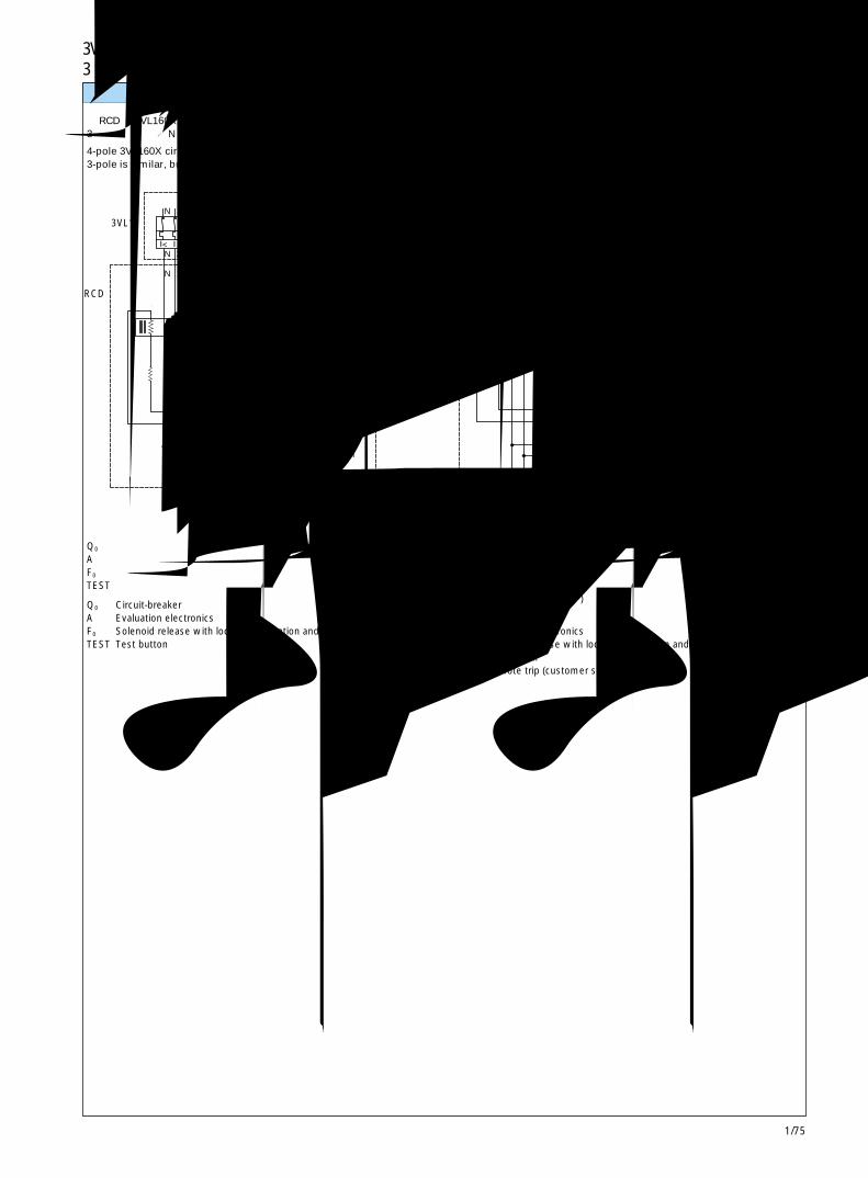
1/75
3VL160X ~ VL1600断路器 3VL160X to VL1600 Circuit-Breakers3 极和 4 极 3- and 4-pole 1
N 2 4 6
X12.3X12.1
+
tdI ∆ n
-
1N
2N <
N 1
3
4
3
5
6
5I
NSK-1093
I I I I
A
6N 42
6
5
5
N
N
N
2 4
1 3
31
td X13.3
X13.2
I
6 8
5
X13.1
PE
X12.1X12.2X12.3
NSK-1094
<I I I I
AI ∆ n
电路图 Circuit diagrams
带RCD的 3VL160X 4极断路器3极类似,但不带N极
4-pole 3VL160X circuit-breaker with RCD shown.3-pole is similar, but without N-pole
Q0 断路器A 电子式计算装置F0 脱扣器电磁线圈,带现场脱扣显示和复位TEST 测试按钮
Q0 Circuit-breakerA Evaluation electronicsF0 Solenoid release with local trip indication and resetTEST Test button
复位RESET
电源断开POWERDISCONNECT
3VL160, VL250和VL400 4极断路器线路图,带远程脱扣器和远程脱扣器显示。3极类似,但不带N极。
4-pole circuit-breaker diagram for 3VL160, VL250 and VL400 circuit-breakers with remote trip and tremote trip indication. 3-pole is similar,but without N-pole.
电源断开POWERDISCONNECT
指示器INDICATOR
复位RESET
远程脱扣器REMOTE TRIP
S0
TESTTEST
F0
F0RCD
3VL2-3VL4
Q0Q0
3VL1
RCD
Q0 断路器A 电子式计算装置F0 脱扣器电磁线圈,带现场脱扣显示和复位TEST 测试按钮S0 远程脱扣器(用户提供)
Q0 Circuit-breakerA Evaluation electronicsF0 Solenoid release with local trip indication and resetTEST Test buttonS0 Remote trip (customer supplied)

1/76
3VL160X ~ VL1600断路器 3VL160X to VL1600 Circuit-Breakers3 极和 4 极 3- and 4-pole
页号
Page
3VL160X, VL160和 VL250断路器
3 极和 4 极断路器 1/78
操作机构 1/79
连接件和相间隔板 1/80
端子盖 1/81
附件 1/82
面板开孔 1/83
插入式插座和附件 1/84
抽屉型 和附件 - 仅限 1/86
3VL160 和 VL250
3VL400断路器
3 极和 4 极断路器 1/88
操作机构 1/88
连接件和相间隔板 1/89
端子盖 1/90
附件 1/91
面板开孔 1/92
插入式插座和附件 1/93
抽屉型和附件 1/94
3VL630断路器
3 极和 4 极断路器 1/96
操作机构 1/96
连接件和相间隔板 1/97
端子盖 1/98
附件 1/99
面板开孔 1/100
插入式插座和附件 1/101
抽屉型和附件 1/102
3VL800断路器
3 极和 4 极断路器 1/104
操作机构 1/104
连接件和相间隔板 1/105
端子盖 1/106
附件 1/107
面板开孔 1/108
尺寸Dimensions
页号
Page
3VL160X, VL160 and VL250 Circuit-Breakers
Circuit-breakers, 3- and 4-pole 1/78
Operators 1/79
Connections and interphase barriers 1/80
Terminal covers 1/81
Accessories 1/82
Panel cutouts 1/83
Plug-in socket and accessories 1/84
Drawout version and accessories -only for 1/86
3VL160 and VL250
3VL400 Circuit-Breakers
Circuit-breakers, 3- and 4-pole 1/88
Operators 1/88
Connections and interphase barriers 1/89
Terminal covers 1/90
Accessories 1/91
Panel cutouts 1/92
Plug-in socket and accessories 1/93
Drawout version and accessories 1/94
3VL630 Circuit-Breakers
Circuit-breakers, 3- and 4-pole 1/96
Operators 1/96
Connections and interphase barriers 1/97
Terminal covers 1/98
Accessories 1/99
Panel cutouts 1/100
Plug-in socket and accessories 1/101
Drawout version and accessories 1/102
3VL800 Circuit-Breakers
Circuit-breakers, 3- and 4-pole 1/104
Operators 1/104
Connections and interphase barriers 1/105
Terminal covers 1/106
Accessories 1/107
Panel cutouts 1/108

1/77
3VL160X ~ VL1600断路器 3VL160X to VL1600 Circuit-Breakers3 极和 4 极 3- and 4-pole 1尺寸Dimensions
页号
Page
3VL1250和 VL1600 断路器
3 极和 4 极断路器 1/109
操作机构 1/110
连接件和相间隔板 1/111
端子盖 1/112
附件 1/113
面板开孔 1/114
带RCD的 3VL160X 断路器
3 极和 4 极断路器 1/115
连接件和相间隔板 1/116
端子盖 1/117
面板开孔 1/118
插入式插座和附件 1/119
带RCD的 3VL160 和 VL250断路器
3 极和 4 极断路器 1/120
连接件和相间隔板 1/121
端子盖 1/122
面板开孔 1/123
插入式插座和附件 1/124
抽屉型和附件 1/125
带RCD的 3VL400 断路器
4 极断路器 1/127
连接件和相间隔板 1/128
端子盖 1/129
面板开孔 1/130
插入式插座和附件 1/131
抽屉型和附件 1/132
页号
Page
3VL1250 und VL1600 Circuit-Breakers
Circuit-breakers, 3- and 4-pole 1/109
Operators 1/110
Connections and interphase barriers 1/111
Terminal covers 1/112
Accessories 1/113
Panel cutouts 1/114
3VL160X Circuit-Breakers with RCD
Circuit-breakers, 3- and 4-pole 1/115
Connections and interphase barriers 1/116
Terminal covers 1/117
Panel cutouts 1/118
Plug-in socket and accessories 1/119
3VL160 and VL250 Circuit-Breakers with RCD
Circuit-breakers, 3- and 4-pole 1/120
Connections and interphase barriers 1/121
Terminal covers 1/122
Panel cutouts 1/123
Plug-in socket and accessories 1/124
Drawout version and accessories 1/125
3VL400 Circuit-Breakers with RCD
Circuit-breaker, 4-pole 1/127
Connections and interphase barriers 1/128
Terminal covers 1/129
Panel cutouts 1/130
Plug-in socket and accessories 1/131
Drawout version and accessories 1/132
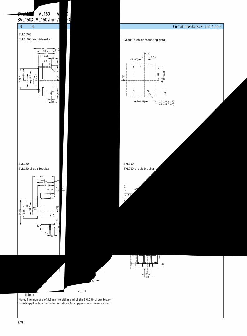
1/78
3VL160X,VL160 和 VL250 断路器3VL160X, VL160 and VL250 Circuit-Breakers
X
Z
X
Y
X
Y
2X 5.2 (3P)4X 5.2 (4P)
31.5
101.
5 58
63.5
139.5 (4P)
16 32
84
2.5
319
90.5 106.5
87 81.5
1916
9.5
16 19
157.
5
19
104.5 (3P)
4
35
12
2.5
71.5
2052.5
129.
5 13
3
35
70 (4P)
35 (3P)
65
2411
4.5
17.5
ON I
OFF O
X
35
NS
K-8
839a
5.2
Y
X
Z
120.
5 63
.5
194
31.558
90.5 106.5
87 81.5
52.5
1124
16
139.5 104.5
4 -(250)2.5-(160)
88.5
15
.5
35
149
32
24.5
7 13
12
17.5 5.2
75.5
174.
5
X
Y
35 35 6X
NS
K-8
840
(8)
X
(8)
Y
X
2X 5.2 (3P)4X 5.2 (4P)
Y
139.5 104.5
5.5
88.5
5.
5 11
70 (4P)
185.
5 149
52.5
18
13
24.5
11.5
8.4
75.5
17.5
174.
5
35 (3P)
131.
5 19
.5
17.5
65
35 35 35 6X
1632
Y
NS
K-8
841
3 极和 4 极断路器 Circuit-breakers, 3- and 4-pole
3VL160X断路器
3VL160X circuit-breaker
3VL160断路器
3VL160 circuit-breaker
注: 只有当使用铜或铝电缆用端子时,才可在 3VL250 断路器的任何一端增加 5.5mm。
Note: The increase of 5.5 mm to either end of the 3VL250 circuit-breakeris only applicable when using terminals for copper or aluminium cables.
断路器安装详图
Circuit-breaker mounting detail
3VL250断路器
3VL250 circuit-breaker
3VL160和 VL250断路器安装详图
3VL160 and VL250circuit-breakers mounting detail
典型
TY
PIC
AL
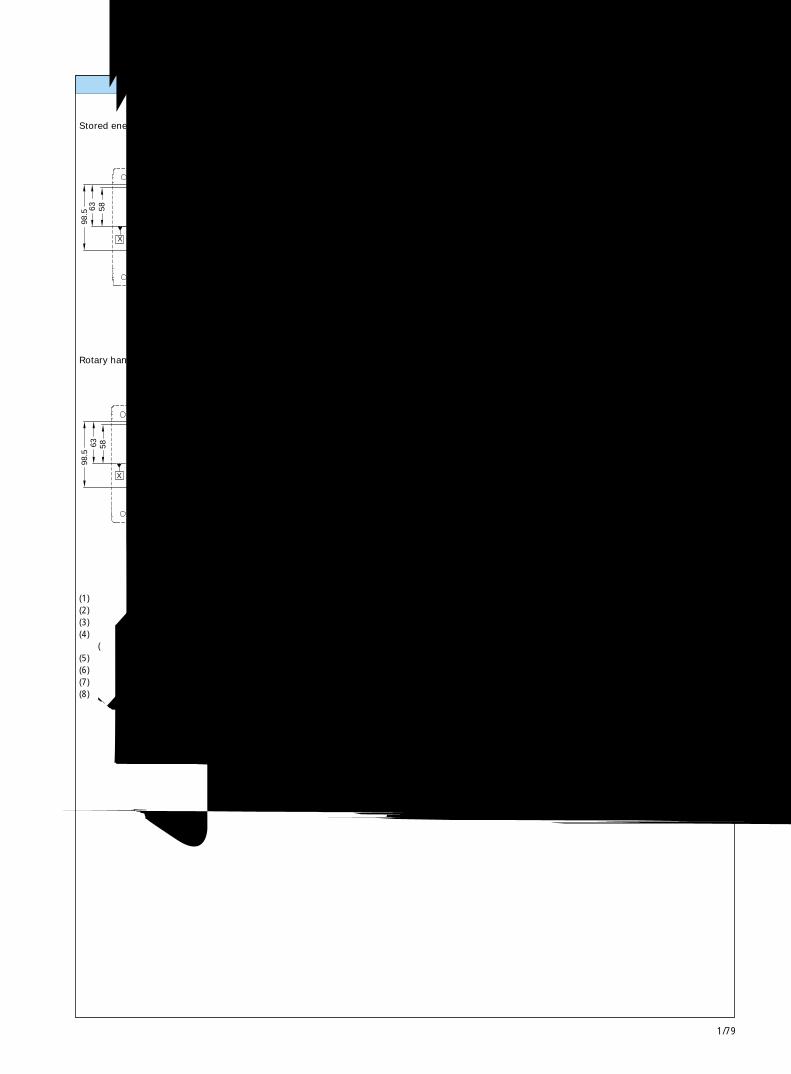
1/79
3VL160X,VL160 和 VL250断路器3VL160X, VL160 and VL250 Circuit-Breakers 1
(7)
X
(7)
(4)
X
Y
(7)
(7)
(1)
CL
(6)
(4)
226.5
63
58
98.5
104.5 52
47.5 (5) 95
(5)
88.5
140
14
1 - 3
27.5
ON
OOFF
I ON
OOFF
I
Y
X
Z
NS
K-8
842
(2)
(2)
(4)
(1)(2)
(2)
CL
(3)(4)
(6)
98.5
58
63
47.5 (5) 95
52 104.5
(5)
88.5
125
38.5
14
1 - 3
76
14.5 Y
TRIPPED
X X
TRIPPED
Y
X
Z
NS
K-8
843
储能操作机构
Stored energy operator
旋转手柄操作机构
Rotary handle operator
(1) 柱形锁(2) 旋转手柄(3) 挂锁钩(4) 柜门开孔面框
(用于带操作机构的断路器)(5) 柜门接口凸缘(6) 柜门外表面(7) 储能操作机构(8) 凸耳护罩
操作机构 Operators
(1) Cylinder locks(2) Rotory handle(3) Padlock hook(4) Cover frame for door cutout
(for circuit-breaker with operator)(5) Door interface ledge(6) Outside surface of cabinet door(7) Stored energy operator(8) Lug shield

1/80
3VL160X,VL160 和 VL250 断路器3VL160X, VL160 and VL250 Circuit-Breakers
(2)
(1)
(10)
(6)
(2)
(7)
(1) (1)
29
C
BA
35 (4P)
35 27
D
EF
6.5 19
9.5
87
HG
44.5 Y
35
X
Z
X
44.5(4P) Y
X
NSK-8844b K
J J
K
44.5
(M12)
(7)
(3)
1 - 3
1 - 3
25.5
BA
109 (4)25.5 Z
53.5(5)
X
NS
K-8
845a
(4)
(5)
(7)
(3)
B
25
A
1 - 3
11
108.5 (8)
51.5(9)
Z
X
(8)
(9)
4
1- 363
120.5
NS
K-8
846a
Z
连接件和相间隔板 Connections and interphase barriers
带背后端子长圆杆和短圆杆的断路器
Circuit-breaker with rear terminals round stock -long and short length
带螺纹的柱螺栓THREADEDSTUD
(1) 相间隔板(2) 正面母排连接件(3) 端子盖(标准)(4) 带螺纹的背面端子,圆杆(长)(5) 带螺纹的背面端子,圆杆(短)(6) 柜门外表面(7) 安装表面(8) 背后端子,扁平圆杆(长)(9) 背后端子,扁平圆杆(短)(10) 张开式正面母排连接件
(1) Interphase barrier(2) Front busbar connection pieces(3) Terminal covers (standard)(4) Threaded rear terminals, round stock (long)(5) Threaded rear terminals, round stock (short)(6) Outside surface of cabinet door(7) Mounting surface(8) Rear terminals, round stock flat (long)(9) Rear terminals, round stock flat (short)(10) Flared front busbar connection pieces
A B
VL160X 71.5 133
VL160 75.5 149
VL250 75.5 149
带背后端子长平圆杆和短平圆杆的断路器
Circuit-breaker with rear terminals round stock flat-long and short length
A B C D E F G H J K
VL160X 242 128.5 116 222 267.5 138.5 222 116 20 7
VL160 258 130 120 238 284 142.5 238 120 20 7
VL250 264 133 120 238 284 142.5 238 120 22 11
典型 TYPICAL
典型 TYPICAL
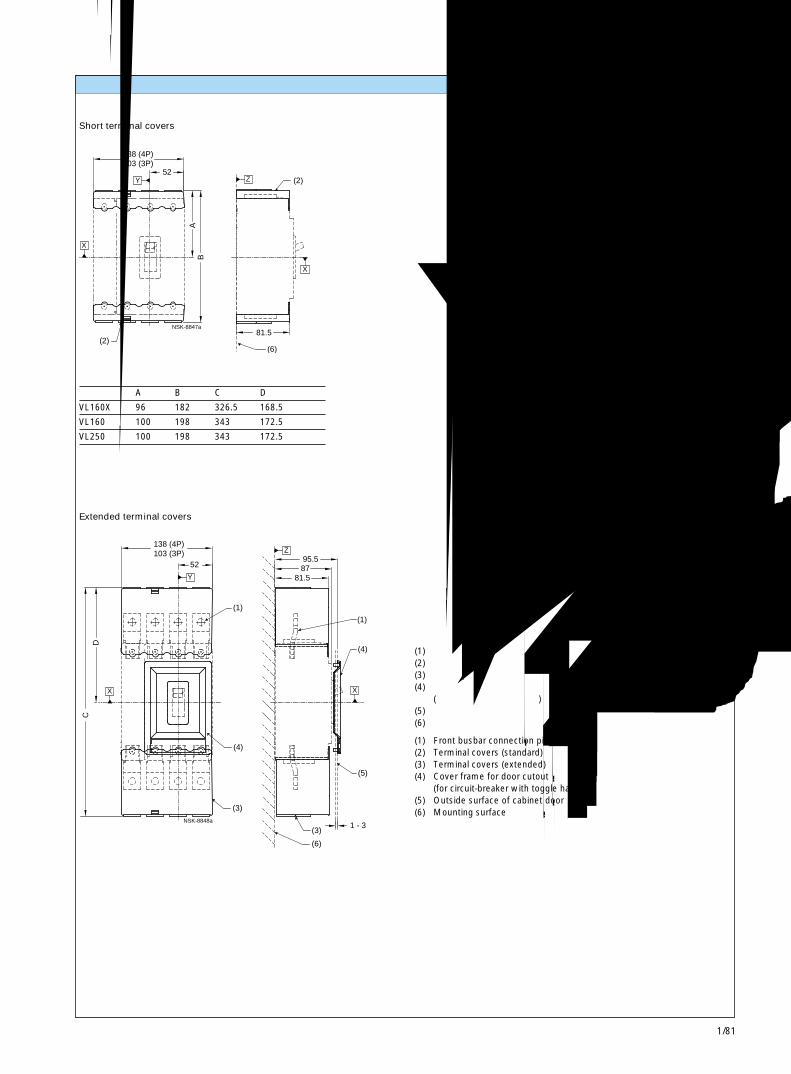
1/81
3VL160X,VL160 和 VL250断路器3VL160X, VL160 and VL250 Circuit-Breakers 1
(2)(6)
(2)
81.5
138 (4P)103 (3P)
52
BA
Y
X
NSK-8847a
Z
X
(3)
(4)
(1)
(3)
(6)
(4)
(5)
(1)
DC
87 81.5
138 (4P)103 (3P)
52
1 - 3
95.5
Y
X X
Z
NSK-8848a
短的端子盖
Short terminal covers
加长的端子盖
Extended terminal covers
(1) 正面母排连接件(2) 端子盖(标准)(3) 端子盖(加长)(4) 柜门开孔面框
(用于带扳动手柄的断路器)(5) 柜门外表面(6) 安装表面
(1) Front busbar connection pieces(2) Terminal covers (standard)(3) Terminal covers (extended)(4) Cover frame for door cutout
(for circuit-breaker with toggle handle)(5) Outside surface of cabinet door(6) Mounting surface
A B C D
VL160X 96 182 326.5 168.5
VL160 100 198 343 172.5
VL250 100 198 343 172.5
端子盖 Terminal covers
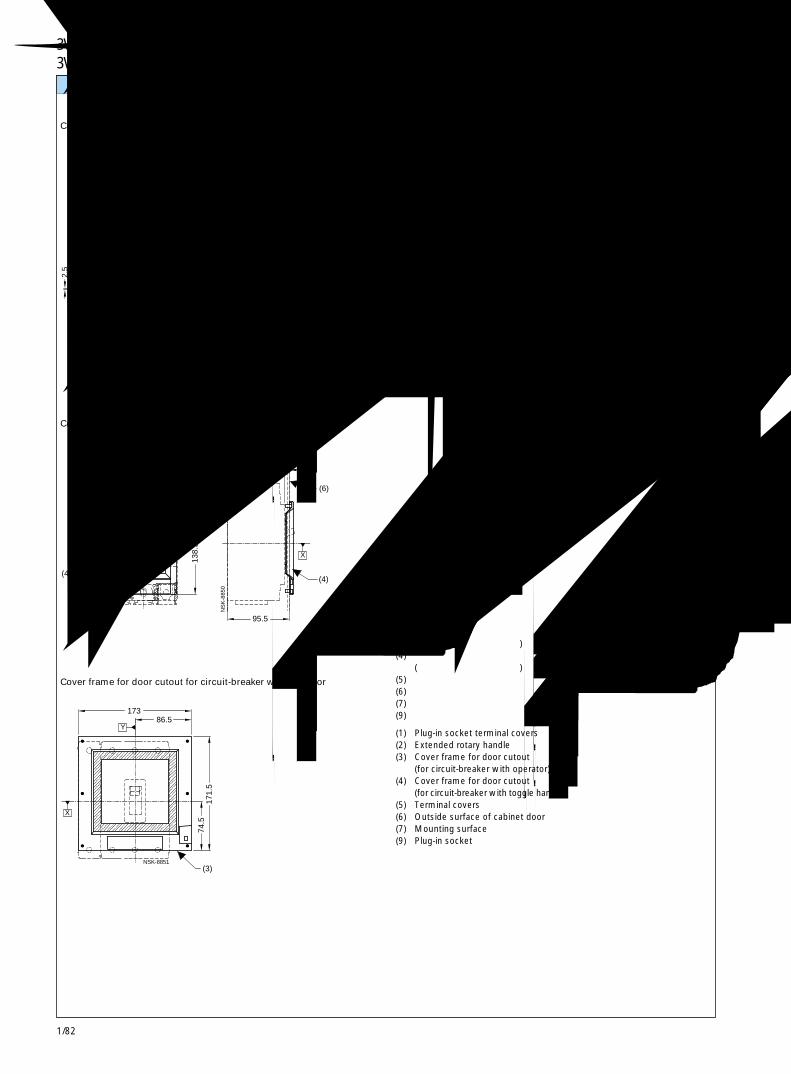
1/82
3VL160X,VL160 和 VL250 断路器3VL160X, VL160 and VL250 Circuit-Breakers
(5)
(7)(1)
(6) (5)
(2)
(9)
(1)
NSK-8849
300 MAX - 60 MIN
2.5
58 22
22
541 MAX - 301 MIN
28
61.5
236.5 222.5
78.5
Z
X
1.5 - 4
(4)(4)
(6)
138.
5 61
.5
101.5 51 1 - 3
95.5
9 Y
X
X
Z
NS
K-8
850
(3)
173 86.5
74.5
17
1.5
Y
X
NSK-8851
附件 Accessories
带加长手柄旋转操作机构的断路器
Circuit-breaker with extended handle rotary operator
带扳动手柄的断路器用柜门开孔面框
Cover frame for door cutout for circuit-breaker with toggle handle
带操作机构的断路器用柜门开孔面框
Cover frame for door cutout for circuit-breaker with operator
(1) 插入式插座端子盖(2) 加长旋转手柄(3) 柜门开孔面框
(用于带操作机构的断路器)(4) 柜门开孔面框
(用于带扳动手柄的断路器)(5) 端子盖(6) 柜门外表面(7) 安装表面(9) 插入式插座
(1) Plug-in socket terminal covers(2) Extended rotary handle(3) Cover frame for door cutout
(for circuit-breaker with operator)(4) Cover frame for door cutout
(for circuit-breaker with toggle handle)(5) Terminal covers(6) Outside surface of cabinet door(7) Mounting surface(9) Plug-in socket
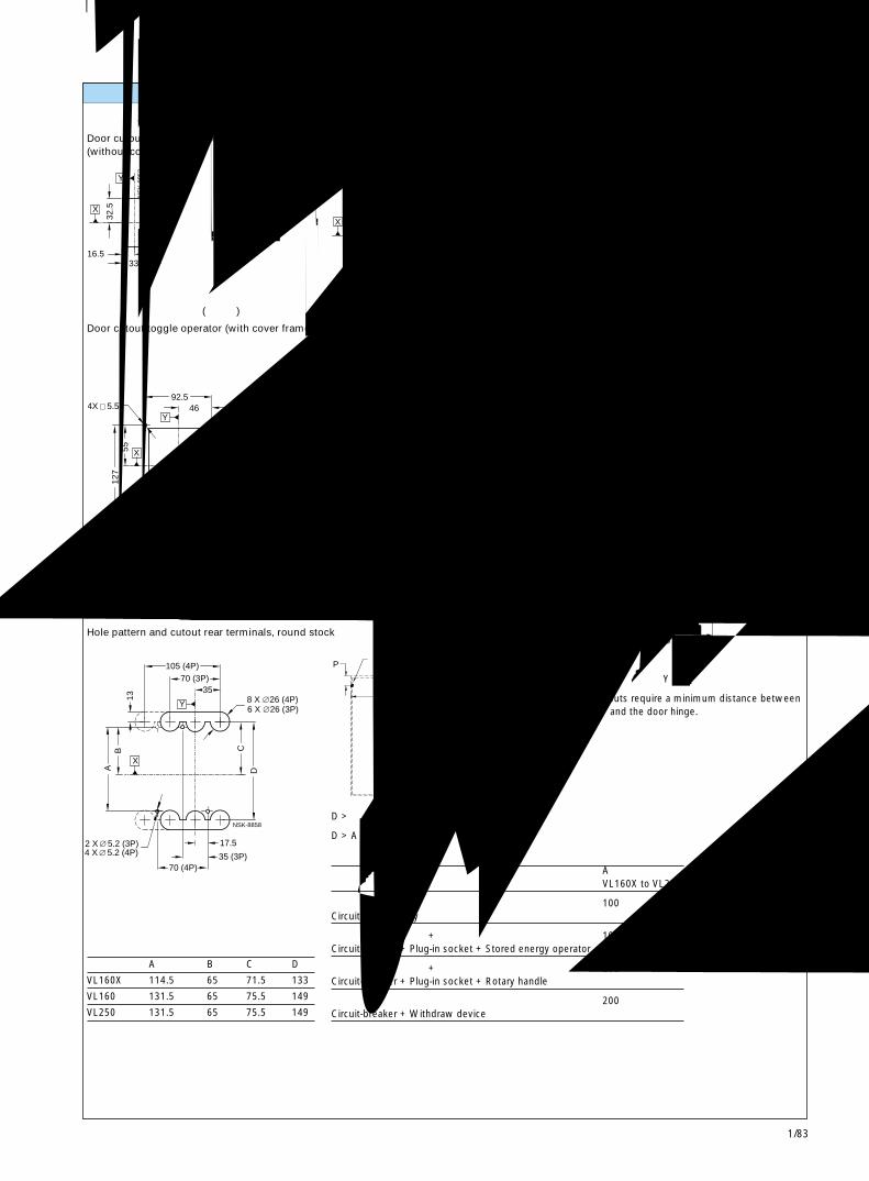
1/83
3VL160X,VL160 和 VL250断路器3VL160X, VL160 and VL250 Circuit-Breakers 1
Y
X
16.5 33
32.5
65
NS
K-8
852
X
Y
96 48
59
90
NSK-8853
X
32.5
42-50
4X
2.5
65
32.5
65
3
NSK-8854
Y
∅
4.5∅
X
Y
41.5
46 5.5
127
55
83
92.5
105
52
NS
K-8
855a
∅4XY
X
159
79.5
11
80
156.5
83
73.5
160.5
81
142
132.
5
5.5
NSK-8856a
6X
X
Y
BA
13
35 (3P)70 (4P)
C
17.5
3570 (3P)
105 (4P)
D
6 X 26 (3P)
NSK-8858
2 X 5.2 (3P) 4 X 5.2 (4P)
8 X 26 (4P)
P Y
D
NSK-8786
面板开孔 Panel cutouts
断路器的扳动手柄门开孔 (不带面框)
Door cutout toggle operator(without cover frame)
断路器的扳动手柄门开孔 (带面框)
Door cutout toggle operator (with cover frame)
圆杆背后端子的孔型和开孔
Hole pattern and cutout rear terminals, round stock
旋转操作机构和储能操作机构门开孔 (不带面框)
Door cutout rotary handle operator and storedenergy operator (without cover frame)
旋转操作机构、储能操作机构和加长框的门开孔
(带面框)Door cutout rotary handle operator, stored energyoperator and extended escutcheon(with cover frame)
加长旋转操作机构门开孔
Door cutout extended handle rotary operator
带背后母排连接件的插入式插座的孔型和开孔
Hole pattern and cutout for plug-in socketwith rear busbar connection pieces
注 门开孔要求在基准轴 Y 和门铰链之间的最小间隔。
Note: Door cutouts require a minimum distance betweendatum Y and the door hinge.
柜门铰链点Door HingePoint
AVL160X to VL250
仅有断路器 100Circuit-breaker only
断路器 + 插入式插座 + 储能操作机构 100Circuit-breaker + Plug-in socket + Stored energy operator
断路器 + 插入式插座 + 旋转手柄 200Circuit-breaker + Plug-in socket + Rotary handle
断路器 + 抽出式装置 200Circuit-breaker + Withdraw device
D > 表中的 A + (P x 5)
D > A from table + (P x 5)
A B C D
VL160X 114.5 65 71.5 133
VL160 131.5 65 75.5 149
VL250 131.5 65 75.5 149
38
22
44.5 (3P)88.9(4P)
4X
155.
5
92 57
38
143 (3P)187.5 (4P)
71.5
289
NSK-8962
7.1
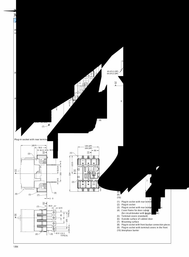
1/84
3VL160X,VL160 和 VL250 断路器3VL160X, VL160 and VL250 Circuit-Breakers
X
Y
Y
X
Z
X
(4)
(6)
(9)
(5)
(7)
(9)
(8)
(8)
(9)
(10)
70 (4P)
1 - 3
5
28.5
174 165.5
38.5 61.5
78.5
25.5
430
12.5
216.
5
135 (4P)100 (3P)35 50
54
258
130.
5
194
98
35 (3P)17.5
5.2 (3P)
NSK-8859
5.2 (4P)4X6X
Y
X
Z
X
Z
(2)
(5)(7)(1)
(7)
(2)
(3)
(2)
(1)
5 52
.5
45.5
1 - 3
12.5
25.5
10
5 70 35
10
2 5
224
113.
5
78.5 165.5
61.5 58.5 50
135 (4P)100 (3P)
8 X 11.1
NS
K-8
860a
X
(3)
插入式插座和附件 Plug-in socket and accessories
带正面母排连接件的插入式插座
Plug-in socket with front busbarconnection pieces
带扁平母排背面端子的插入式插座
Plug-in socket with rear terminals flat bus
带正面母排连接件的插入式插座的孔型
Hole pattern for plug-in socketwith front busbar connection pieces
(1) 带背面端子盖的插入式插座(2) 插入式插座(3) 带扁平母排背面端子的插入式插座(4) 柜门开孔面框
(用于带扳动手柄的断路器)(5) 端子盖(标准)(6) 柜门外表面(7) 安装表面(8) 带正面母排连接件的插入式插座(9) 前部带端子盖的插入式插座(10) 相间隔板
(1) Plug-in socket with rear terminal covers(2) Plug-in socket(3) Plug-in socket with rear terminals flat bus(4) Cover frame for door cutout
(for circuit-breaker with toggle handle)(5) Terminal covers (standard)(6) Outside surface of cabinet door(7) Mounting surface(8) Plug-in socket with front busbar connection pieces(9) Plug-in socket with terminal covers in the front(10) Interphase barrier
典型TYPICAL
典型 TYPICAL典型 TYPICAL
典型
TY
PIC
AL
典型
TY
PIC
AL
典型
TY
PIC
AL
典型 TYPICAL
典型
TY
PIC
AL
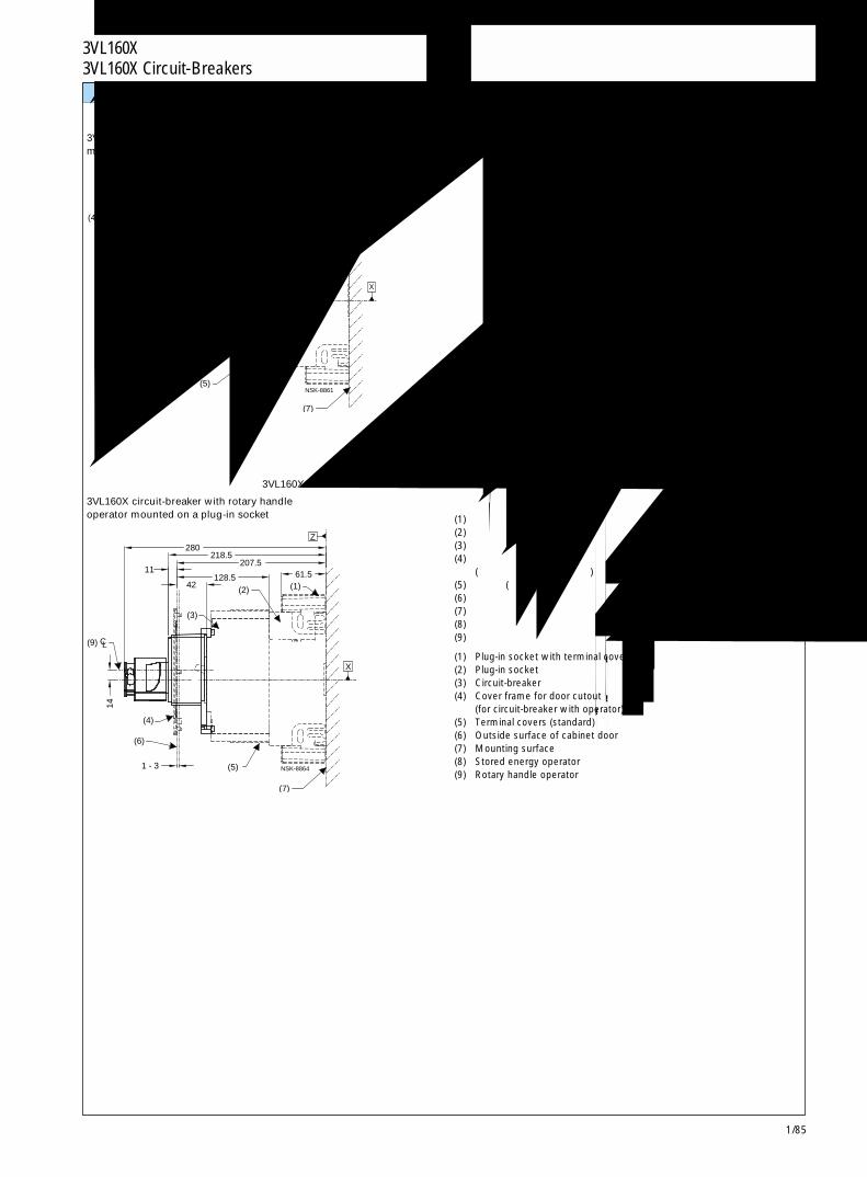
1/85
3VL160 和 VL250 断路器3VL160 and VL 250 Circuit-Breakers 1
(8)
Z
X
(2)
CL
(6) (5)
(4)
(3)
(7)
(1)
27.5
14
1 - 3
140 226.5 305.5 333
61.5
NSK-8861
X
(9)
Z
(4)
(6)
(5)
(7)
(2)
CL
(3)
(1)
1 - 3
14
11
280
42 128.5
218.5 207.5
61.5
NSK-8864
插入式插座和附件 Plug-in socket and accessories
带有插入式插座和储能操作机构的 3VL160X断路器
3VL160X circuit-breaker with stored energy operatormounted on a plug-in socket
带有插入式插座和旋转手柄操作机构的 3VL160X断路器
3VL160X circuit-breaker with rotary handleoperator mounted on a plug-in socket (1) 带端子盖的插入式插座
(2) 插入式插座(3) 断路器(4) 柜门开孔面框
(用于带操作机构的断路器)(5) 端子盖(标准)(6) 柜门外表面(7) 安装表面(8) 储能操作机构(9) 旋转手柄操作机构
(1) Plug-in socket with terminal covers(2) Plug-in socket(3) Circuit-breaker(4) Cover frame for door cutout
(for circuit-breaker with operator)(5) Terminal covers (standard)(6) Outside surface of cabinet door(7) Mounting surface(8) Stored energy operator(9) Rotary handle operator
3VL160X 断路器3VL160X Circuit-Breakers
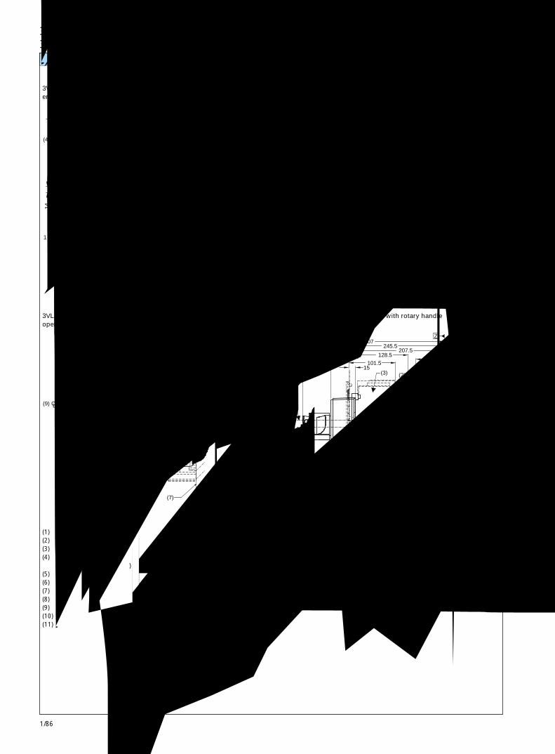
1/86
3VL160 和 VL250 断路器3VL160 and VL 250 Circuit-Breakers
(8)
(3)
CL
(6)
(11)
(5)
(4)
(10)(7)
(2) (1)
Z
X
1 - 3
14
27.5
140
333 305.5
226.5 61.5
NS
K-8
909
(9)
X
(11)
(5)(6)
(4)
(10)(7)
CL
(3)
(2) (1)
Z
14
1 - 3
280
11
218.5
128.5 42
207.5 61.5
NS
K-8
910
(8)
(1)
CL
(6)
(4)
(11)
(5)(10)
(7)
(3)(2)
X
Z
14
1 - 3
54.5 305.5
226.5
360
113 199.5
61.5 NS
K-8
780
(9)
X
(4)
(6) (5)(10)
(7)
(1)
CL
(2)(3)
Z
1 - 3
14
101.5 38
15
307
207.5 128.5
245.5
61.5
NS
K-8
781
抽屉型和附件 Drawout version and accessories
带储能操作机构的 3VL160和 VL250断路器 (运行位置)
3VL160 and VL250 circuit-breakers with storedenergy operator (engaged position)
带旋转手柄操作机构的 3VL160和 VL250断路器(运行位置)
3VL160 and VL250 circuit-breakers with rotary handleoperator (engaged position)
(1) 带端子盖的插入式插座(2) 插入式插座(3) 断路器(4) 柜门开孔面框
(用于带操作机构的断路器)(5) 端子盖(标准)(6) 柜门外表面(7) 安装表面(8) 储能操作机构(9) 旋转手柄操作机构(10) 抽出式装置(11) 抽出式曲柄位置
带储能操作机构的 3VL160和 VL250断路器(断开位置)
3VL160 and VL250 circuit-breakers with storedenergy operator (disengaged position)
带旋转手柄操作机构的 3VL160和 VL250断路器(断开位置)
3VL160 and VL250 circuit-breakers with rotary handleoperator (disengaged position)
(1) Plug-in socket with terminal covers(2) Plug-in socket(3) Circuit-breaker(4) Cover frame for door cutout
(for circuit-breaker with operator)(5) Terminal covers (standard)(6) Outside surface of cabinet door(7) Mounting surface(8) Stored energy operator(9) Rotary handle operator(10) Withdraw device(11) Withdraw crank location
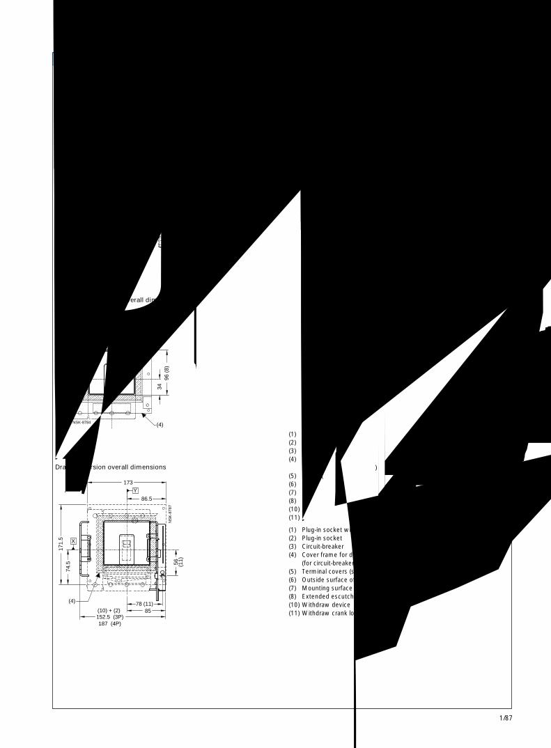
1/87
3VL160 和 VL250 断路器3VL160 and VL 250 Circuit-Breakers 1
(8)
Z
X
(10)
(6) (11)
(5)
(4)
CL
(3)
(7)
(2)(1)
218.5
1 - 3
14
11
42 128.5
207.5
61.5
NS
K-8
782
(8)
Z
X
(6)
CL
(10)(11)
(5)
(7)
(3)(1)
(2)
14
1 - 3
14.5
38 128.5
101.5
245.5 207.5
61.5
NS
K-8
783
(4)
X
(8)
Y
101 (8)
50.5
96 (
8)34
NSK-8784
Y
X
(4)
(10) + (2)152.5 (3P)187 (4P)
171.
5 74
.5
85
173
86.5
78 (11)
56
(11)
NS
K-8
787
抽屉型和附件 Drawout version and accessories
带加长框的 3VL160和 VL250断路器(运行位置)
3VL160 and VL250 circuit-breakers with extendedescutcheon (engaged position)
加长框外形尺寸
Extended escutcheon overall dimensions
抽屉型外形尺寸
Drawout version overall dimensions
带加长框的 3VL160和 VL250断路器(断开位置)
3VL160 and VL250 circuit-breakers with extendedescutcheon (disengaged position)
(1) 带端子盖的插入式插座(2) 插入式插座(3) 断路器(4) 柜门开孔面框
(用于带操作机构的断路器)(5) 端子盖(标准)(6) 柜门外表面(7) 安装表面(8) 加长框(10) 抽出式装置(11) 抽出式曲柄位置
(1) Plug-in socket with terminal covers(2) Plug-in socket(3) Circuit-breaker(4) Cover frame for door cutout
(for circuit-breaker with operator)(5) Terminal covers (standard)(6) Outside surface of cabinet door(7) Mounting surface(8) Extended escutcheon(10) Withdraw device(11) Withdraw crank location
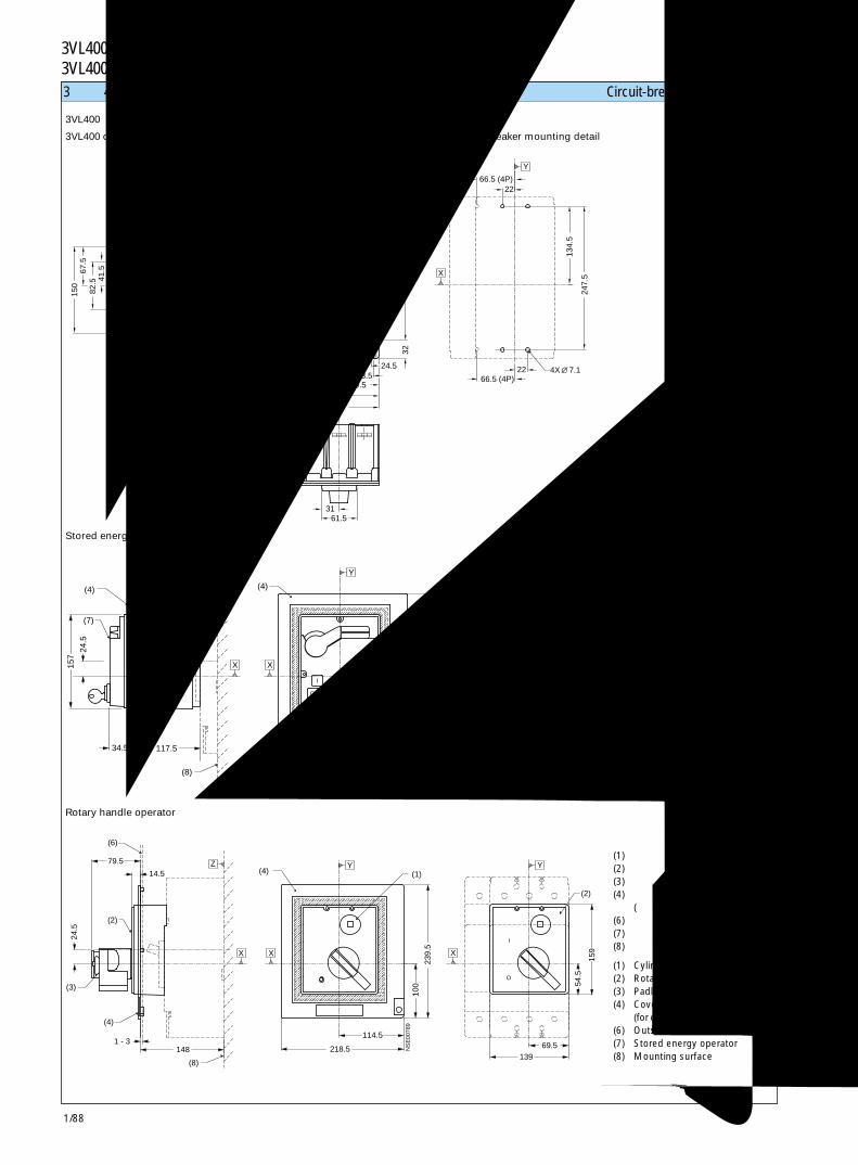
1/88
3VL400 断路器3VL400 Circuit-Breakers
224
(8)
(4)
(7)
34.5
24.5
157
117.5
(7)54
.5
69.5
159
100
239.
5
114.5 218.5
(1)
139
(4)
OO
II
YZ
X X
Y
X
NS
E00
788
�
(6)
(8)
148
14.5
79.5
(2)
24.5
(4)
(3)
1 - 3
(2)
159
54.5
69.5
(1)
239.
5
100
114.5
218.5139
(4)Y Y
XX
Z
X
NS
E00
789
I
O
3极和 4极断路器 Circuit-breakers, 3- and 4-pole
储能操作机构
Stored energy operator
断路器安装详图
Circuit-breaker mounting detail
旋转手柄操作机构
Rotary handle operator
(1) 柱形锁(2) 旋转手柄操作机构(3) 挂锁钩(4) 柜门开孔面框
(用于带操作机构的断路器)(6) 柜门外表面(7) 储能操作机构(8) 安装表面
(1) Cylinder locks(2) Rotary handle operator(3) Padlock hook(4) Cover frame for door cutout
(for circuit-breaker with operator)(6) Outside surface of cabinet door(7) Stored energy operator(8) Mounting surface
3VL400断路器
3VL400 circuit-breaker
139 (3P)
183.5 4(P)
61.531
115 106.5
101.5
138.5
32
46.5
16.5
150
82.5
41.567
.5 13
4.5
2266.5 (4P)
Y44.5 44.5
150.
5
44.5
118.
5
247.
5
4X 22 66.5 (4P)
215.
5
69.5
32
33.524.5
279.
5
8.3
O
Z
X X
Y
X
NSK-8947a7.1
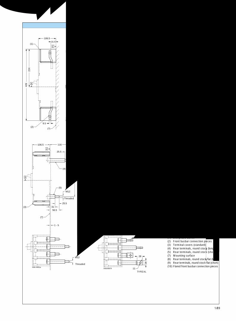
1/89
3VL400 断路器3VL400 Circuit-Breakers 1
409
9.5
426
(7)(2)
409
19
15
38
(10)
15
(1)
(2)
30.5 (1)19
(1)
106.531.5
224
63.5
78.5
215.
5
63.5 63.530.5
119.5 (3P)163.5 (4P)
44.5 44.5
(2)
200.
5
379
200.
5
379
215.
5
157.5 (3P)221 (4P)
O
I
OFF
ON
OFF O
ON IX
Z
X
YY
X
NSE00869
44.5
11 11
25.5
116
25.5
(4)
(5)
106.5
31 56.5
1 - 5
(7)
(3)
215.
5
M12
M12
Z
X
NSK-8951a
215.
5
91
(8)
157171.5106.5
28
28
98.5113
1 - 5
(7)
(3)
(9)
8
X
Z
NSE00878 11
32.5
连接件和相间隔板 Connections and interphase barriers
带螺纹
Threaded
带螺纹Threaded
(1) 相间隔板(2) 正面母排连接件(3) 端子盖(标准)(4) 背后端子,圆杆(长)(5) 背后端子,圆杆(短)(7) 安装表面(8) 背后端子,扁平圆杆(长)(9) 背后端子,扁平圆杆(短)(10) 扩口正面母排连接件
(1) Interphase barrier(2) Front busbar connection pieces(3) Terminal covers (standard)(4) Rear terminals, round stock (long)(5) Rear terminals, round stock (short)(7) Mounting surface(8) Rear terminals, round stock flat (long)(9) Rear terminals, round stock flat (short)(10) Flared front busbar connection pieces
典型 TYPICAL
典型 TYPICAL
典型
TY
PIC
AL
典型
TY
PIC
AL
典型TYPICAL
典型
TYPICAL
典型TYPICAL
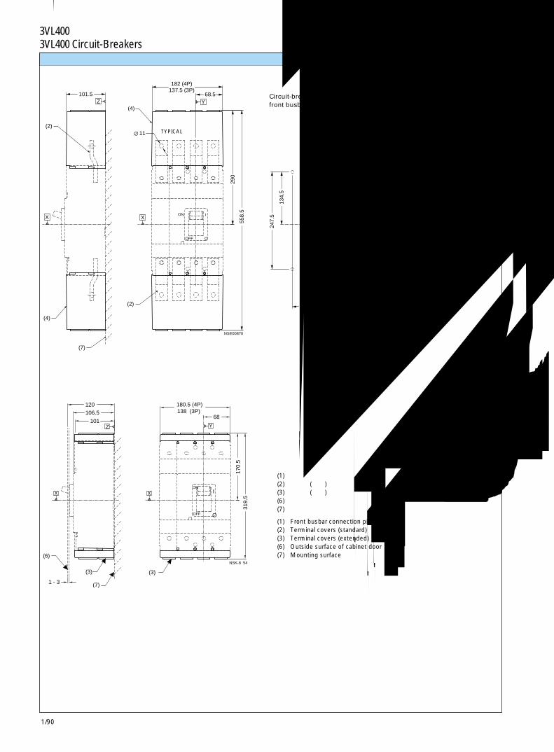
1/90
3VL400 断路器3VL400 Circuit-Breakers
101.5
(7)
(4)
(2)
22
89 (4P)44.5
(2)
68.5
182 (4P)137.5 (3P)
4 x ÿ 7.1
134.
5
247.
5
290
558.
5
(4)
OOFF
ION
Z
X X
Y
Y
X
NSE00870
11
120
(6)
1 - 3
68
180.5 (4P)138 (3P)
Z
106.5
101
170.
5 31
9.5
(3)
(7)
(3)
I
O
ON
OFF
X X
Y
NSK-8 54
端子盖 Terminal covers
(1) 正面母排连接件(2) 端子盖(标准)(3) 端子盖(加长)(6) 柜门外表面(7) 安装表面
(1) Front busbar connection pieces(2) Terminal covers (standard)(3) Terminal covers (extended)(6) Outside surface of cabinet door(7) Mounting surface
断路器安装详图正面母排连接件
Circuit-breaker mounting detailfront busbar connection pieces
典型TYPICAL
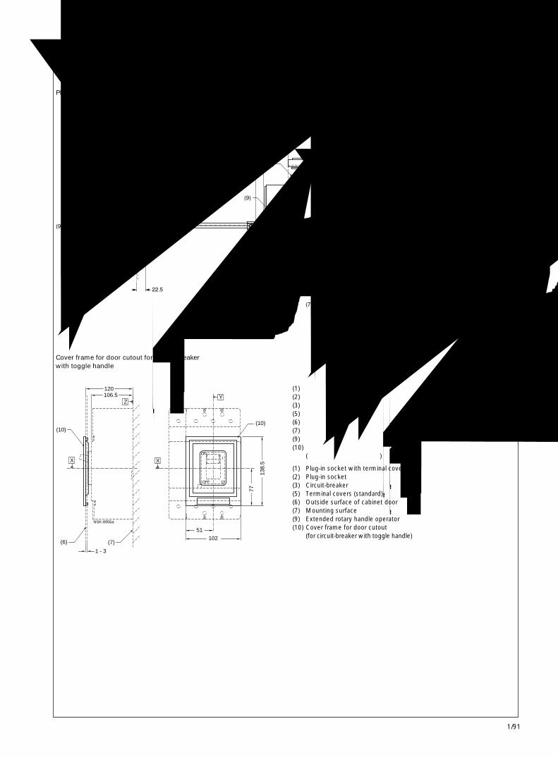
1/91
3VL400 断路器3VL400 Circuit-Breakers 1
L(9)
40
(5)
22.5
0.5
(9)
C
166.5
300 MAX - 60 MIN
101 489.5 MAX - 249.5 MIN
(3)
(9)
(6)
X
(7)
Z
NSE00790
186.5
101.5
(10)(10)
138.
5
106.5 120
102
51
(7)
1 - 3
(6)
77 OFF O
ONIX
Z
X
NSK-8956a
Y
附件 Accessories
加长旋转操作机构的插入式断路器
Plug-in socket rotary handle operator extended handle
带扳动手柄及面框的断路器柜门开孔
Cover frame for door cutout for circuit-breakerwith toggle handle
(1) 带端子盖的插入式插座(2) 插入式插座(3) 断路器(5) 端子盖(标准)(6) 柜门外表面(7) 安装表面(9) 加长旋转手柄操作机构(10) 柜门开孔面框
(用于带扳动手柄的断路器)
(1) Plug-in socket with terminal covers(2) Plug-in socket(3) Circuit-breaker(5) Terminal covers (standard)(6) Outside surface of cabinet door(7) Mounting surface(9) Extended rotary handle operator(10) Cover frame for door cutout
(for circuit-breaker with toggle handle)
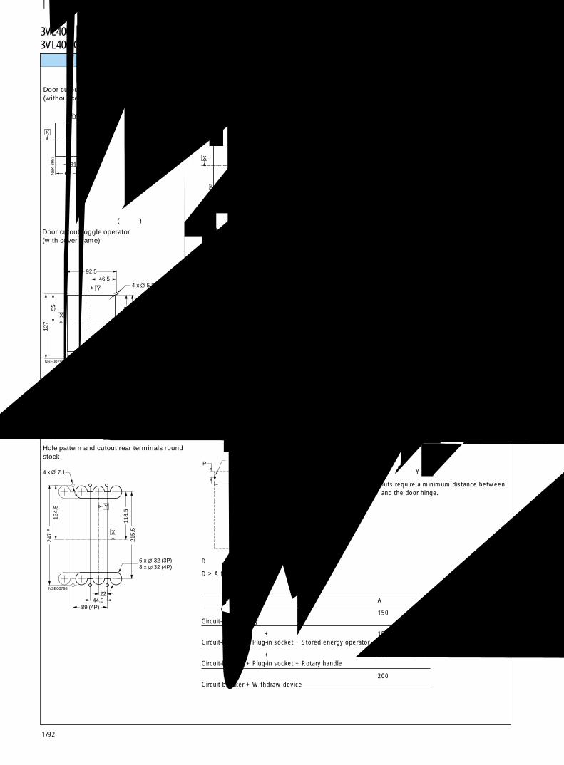
1/92
3VL400 断路器3VL400 Circuit-Breakers
84.5
62
31
42.5
X
Y
NS
K-8
957 15
2.510
1
132.5
66
X
Y
NS
E00
793
88
0.5
7
88 44
44
4XY
X
NS
K-8
959
5.5
64
121.
5 19
4
108 206
6 x 5.5
226.
580
.5
87
175
185
133
20
105.5
14
X
Y
NSE00796
38
22
44.5 (3P)88.9(4P)
4X
155.
5
92 57
38
143 (3P)187.5 (4P)
71.5
289
NSK-8962
7.1
118.
5 21
5.5
2244.5
134.
5
4 x 7.1
247.
5
89 (4P)
Y
X
NSE00798
6 x 32 (3P)8 x 32 (4P)
4 x 5.546.5
92.5
102
51
40.5 81.5
5512
7
X
Y
NSE00795
P Y
D
NSK-8786
面板开孔 Panel cutouts
旋转操作机构、储能操作机构和加长框的门开孔(带面框)
Door cutout rotary handle operator, stored energyoperator and extended escutcheon(with cover frame)
断路器的扳动手柄门开孔 (不带面框)
Door cutout toggle operator(without cover frame)
断路器的扳动手柄门开孔 (带面框)
Door cutout toggle operator(with cover frame)
圆杆背后端子的孔型和开孔
Hole pattern and cutout rear terminals roundstock
旋转操作机构和储能操作机构的门开孔 (不带面框)
Door cutout rotary handle operator and storedenergy operator (without cover frame)
加长旋转操作机构门开孔
Door cutout extended handle rotary operator
带扁平母排背后端子的插入式插座的孔型和开孔
Hole pattern and cutout for plug-in socketwith rear terminals flat bus
注 门开孔要求在基准轴 Y 和门铰链之间的最小间隔。
Note: Door cutouts require a minimum distance betweendatum Y and the door hinge.
门铰链点Door HingePoint
A
仅有断路器 150Circuit-breaker only
断路器 + 插入式插座 + 储能操作机构 150Circuit-breaker + Plug-in socket + Stored energy operator
断路器 + 插入式插座 + 旋转手柄 200Circuit-breaker + Plug-in socket + Rotary handle
断路器 + 抽出式装置 200Circuit-breaker + Withdraw device
D > 表中的 A + (P x 5)
D > A from table + (P x 5)
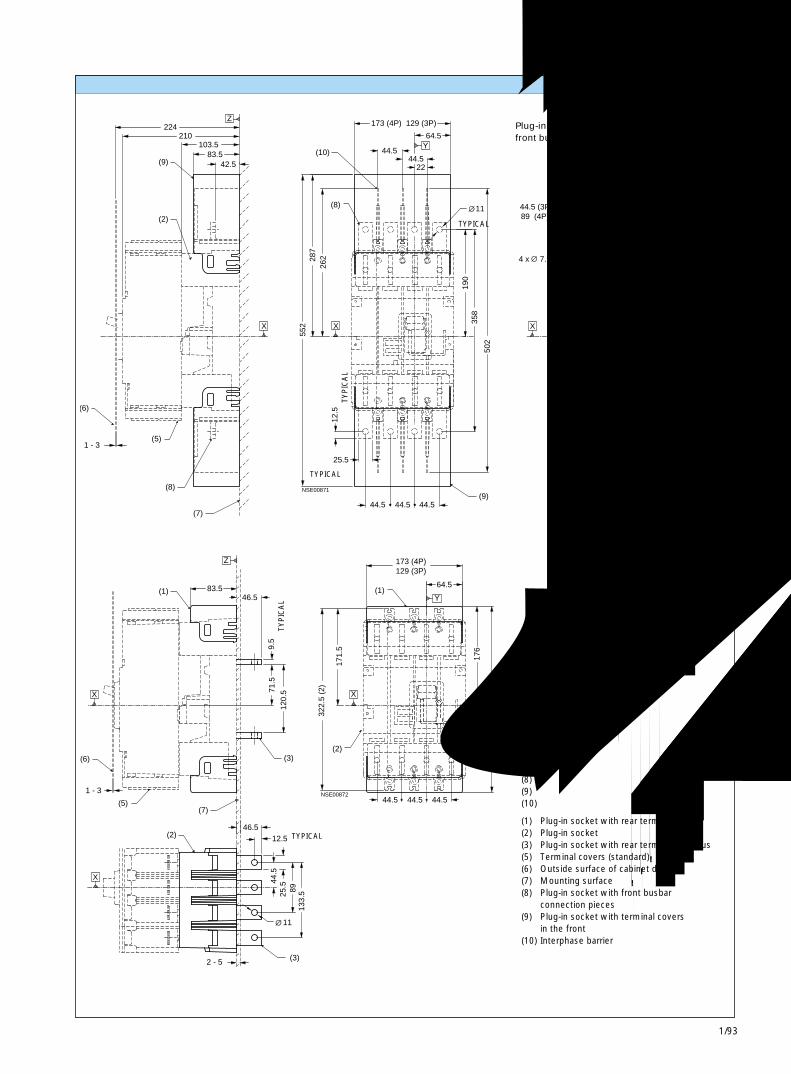
1/93
3VL400 断路器3VL400 Circuit-Breakers 1
358
(5)
(6)
(7)
(8)
1 - 3
289
502
12.5
552
(9)44.5 44.5
25.5
44.5
103.5 83.5
42.5
210 224
(9)
(2)22
156
11
64.5
44.5
2244.5
(10)
(8)
173 (4P) 129 (3P)
190
262 28
7
44.5 (3P)89 (4P)
X X
Z
Y
Y
X
NSE00871
4 x 7.1
83.5
2 - 5
(1)
(7)
(6)
1 - 3
(5)
(2)
173 (4P)
64.5
176
(1)
129 (3P)
171.
5
330
(1)
44.544.5 44.5
(2)
322.
5 (2
)
46.5
9.5
120.
5
(3)
25.5
46.5
89
71.5
133.
5
(3)
44.5
12.5
11
X
Z
X
Y
X
NSE00872
带正面母排连接件的插入式插座的孔型
Plug-in socket hole patternfront busbar connection pieces
(1) 带背后端子盖的插入式插座(2) 插入式插座(3) 带扁平母排背后端子的插入式插座(5) 端子盖(标准)(6) 柜门外表面(7) 安装表面(8) 带正面母排插入件的插入式插座(9) 正面母排连接的端子盖的插入式插座(10) 相间隔板
(1) Plug-in socket with rear terminal covers(2) Plug-in socket(3) Plug-in socket with rear terminals flat bus(5) Terminal covers (standard)(6) Outside surface of cabinet door(7) Mounting surface(8) Plug-in socket with front busbar
connection pieces(9) Plug-in socket with terminal covers
in the front(10) Interphase barrier
典型TYPICAL
典型
TY
PIC
AL
典型
TYP
ICA
L
典型TYPICAL
典型TYPICAL
插入式插座和附件 Plug-in socket and accessories
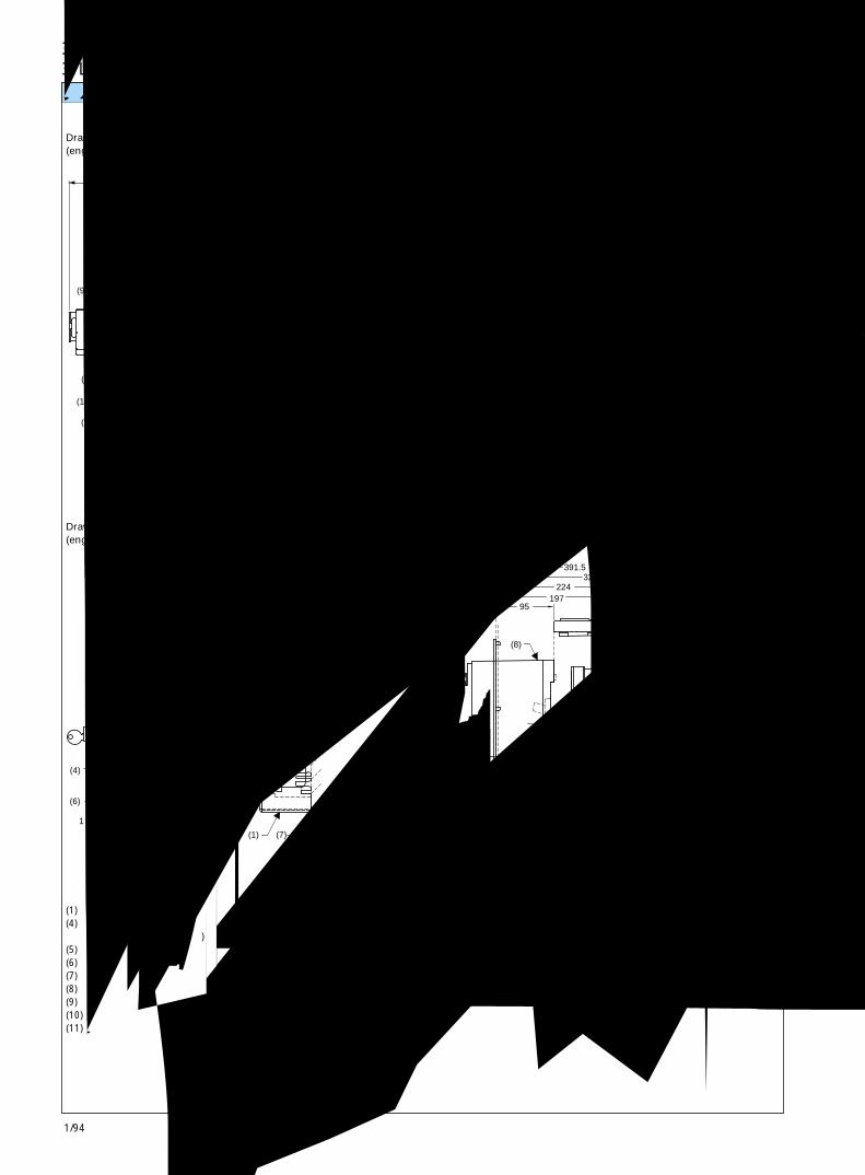
1/94
3VL400 断路器3VL400 Circuit-Breakers
65
1 - 3
(6)
(11)
(4)
(9)
(7)(1)(5)(10)
Z
266
148 251.5
X
NS
E00
873
(7)(1)(5)(10)
(6)
(11)
1 - 3
(4)
27 148
293 251.5
121
65
(9)
Z
X
NS
E00
874
(4)
(6)
1 - 3
122 224
327.5
(8)
(7)(1)(10) (5)
(11)
364.5
X
Z
NS
K-8
970
27
224
95 197
327.5
(8)
(7)(1)
(11)
(10) (5)
(6)
(4)
1 - 3
391.5
Z
XN
SK
-897
1
抽屉型和附件 Drawout version and accessories
旋转操作机构的抽屉型断路器(运行位置)
Drawout version rotary handle operator(engaged position)
储能操作机构插的抽屉型 (运行位置)
Drawout version stored energy operator(engaged position)
(1) 带端子盖的抽屉型(4) 柜门开孔面框
(用于带操作机构的断路器)(5) 端子盖(标准)(6) 柜门外表面(7) 安装表面(8) 储能操作机构(9) 旋转手柄操作机构(10) 抽出式装置(11) 抽出式曲柄位置
旋转操作机构的抽屉型(断开位置)
Drawout version rotary handle operator(disengaged position)
储能操作机构的抽屉型(断开位置)
Drawout version stored energy operator(disengaged position)
(1) Drawout version with terminal covers(4) Cover frame for door cutout
(for circuit-breaker with operator)(5) Terminal covers (standard)(6) Outside surface of cabinet door(7) Mounting surface(8) Stored energy operator(9) Rotary handle operator(10) Withdraw device(11) Withdraw crank location
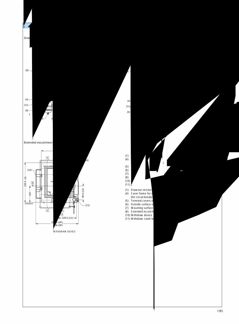
1/95
3VL400 断路器3VL400 Circuit-Breakers 1
(7)(5) (1)(10)
(11)
(6)
1 - 3
(4)
262.5
251.5 148
(8)
Z
XN
SK
-897
2
(7)(1)(5)(10)
(6)
(11)
1 - 3
(4)
251.5
27
289.5
148 120.5
(8)
X
Z
NS
K-8
973
(4)
218.5 (4)114.5
80.5
(11
)
(10)
100
239.
5 (
4)
105.5 (11)
(11)
O
I
OFF
ONX
Y
NSE00875
252.5 (4P) 208 (3P)
加长框的抽屉型 (断开位置)
Drawout version extended escutcheon (disengaged position)
安装在抽出式装置内的加长框
Extended escutcheon mounted in withdraw device
加长框的抽屉型 (运行位置)
Drawout version extended escutcheon (engaged position)
(1) 带端子盖的抽屉型(4) 柜门开孔面框
(用于带操作机构的断路器)(5) 端子盖(标准)(6) 柜门外表面(7) 安装表面(8) 加长框(10) 抽出式装置(11) 抽出式曲柄位置
(1) Drawout version with terminal covers(4) Cover frame for door cutout
(for circuit-breaker with operator)(5) Terminal covers (standard)(6) Outside surface of cabinet door(7) Mounting surface(8) Extended escutcheon(10) Withdraw device(11) Withdraw crank location
抽出式装置WITHDRAW DEVICE
抽屉型和附件 Drawout version and accessories
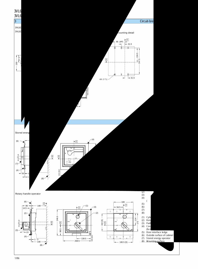
1/96
3VL630 断路器3VL630 Circuit-Breakers
(7)
(4)
(6)
(8)
X
Z
X
Y
(1) X
(4)
Y
117.5
1 - 3
35
27
224 94.5
180.5 (5)139.5
268.5
164
(5)
98.5
246.
5 114
172
189
NS
K-8
810
(3)
(2)
(4)
(6)Z
(8)
X X
Y(1)
(4)
(2)
Y
27
13
14.586
1 - 3148
14894.5
180.5 (5)
98.5
246.
5
139.5268.5
164
(5) 11
4
189
172
NS
K-8
811
X
3极和 4极断路器 Circuit-breakers, 3- and 4-pole
3VL630断路器
3VL630 circuit-breaker断路器安装详图
Circuit-breaker mounting detail
储能操作机构
Stored energy operator
旋转手柄操作机构
Rotary handle operator
(1) 柱形锁(2) 旋转手柄(3) 挂锁钩(4) 柜门开孔面框
(用于带操作机构的断路器)(5) 门接口凸缘(6) 柜门外表面(7) 储能操作机构(8) 安装表面
(1) Cylinder locks(2) Rotary handle(3) Padlock hook(4) Cover frame for door cutout
(for circuit-breaker with operator)(5) Door interface ledge(6) Outside surface of cabinet door(7) Stored energy operator(8) Mounting surface
操作机构 Operators
4X 7.1
Z
X X
Y
X
YY
150.
5
101.5
150 41
.5
82.5
67.5
29 16.5
40
20
20
40
279.
5
106.5 115
138.5 22
63.5 31.5
239.
5
190 (3P)253.5 (4P)
3774
95
20
130.
5
31.5
134.
5 24
7.5
95 (4P)127 (4P)
NS
E-0
0568
a
∅ 8.6 ∅ 7.02X11
63.5
45
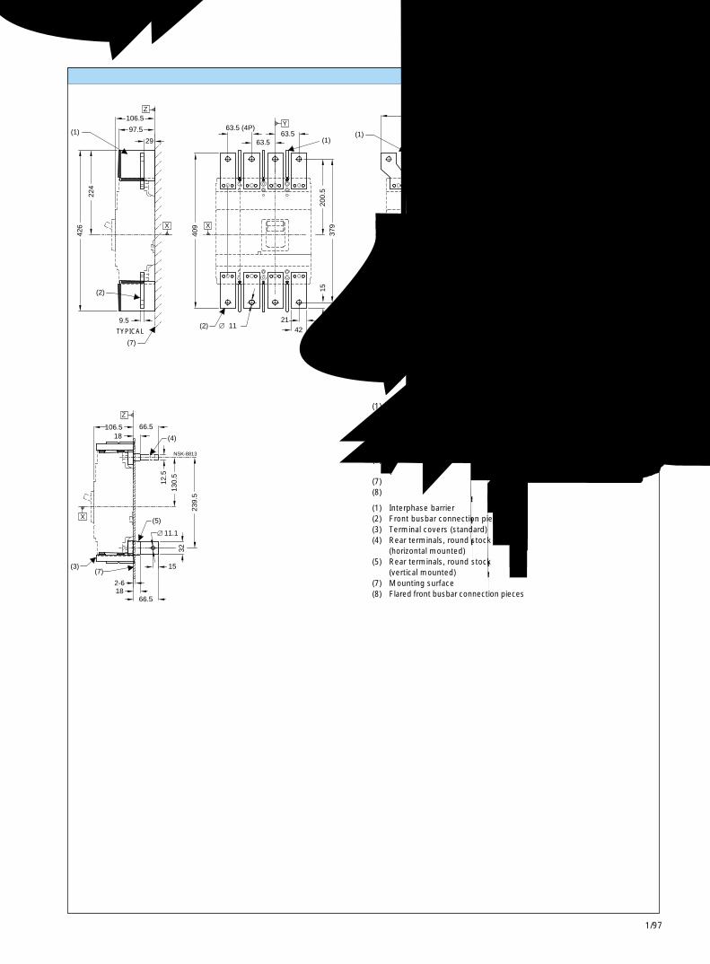
1/97
3VL630 断路器3VL630 Circuit-Breakers 1
Z
(1)
(2)
(7)
X
(2)
Y
(1)
(8)
(1)
X
76
270.5 (4P)
97.5
426
9.5
224
29
106.5
409
63.5 (4P)63.5
2111
63.5
4215
200.
537
925.5
194.5 (3P)97
215.
540
9
200.
5
X
Y
12.5
NSK-8812
12.5
(3)(7)
X
Z
(5)
(4)
2-6
106.518
1866.5
15
66.5
12.5
130.
5
11.1
32
239.
5
NSK-8813
连接件和相间隔板 Connections and interphase barriers
(1) 相间隔板(2) 正面母排连接件(3) 端子盖(标准)(4) 背面端子,圆杆
(水平安装)(5) 背面端子,圆杆
(垂直安装)(7) 安装表面(8) 扩口正面母排连接件
(1) Interphase barrier(2) Front busbar connection pieces(3) Terminal covers (standard)(4) Rear terminals, round stock
(horizontal mounted)(5) Rear terminals, round stock
(vertical mounted)(7) Mounting surface(8) Flared front busbar connection pieces
典型 TYPICAL
典型TYPICAL
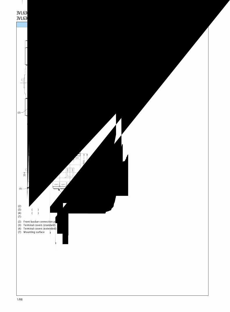
1/98
3VL630 断路器3VL630 Circuit-Breakers
(4)
(2)
(7)
X
(2)
X
Z
Y
101.5
291
560.
5
188 (3P)
251 (4P)
94.5
NSK-8814
端子盖 Terminal covers
(2) 正面母排连接件(3) 端子盖(标准)(4) 端子盖(加长)(7) 安装表面
(2) Front busbar connection pieces(3) Terminal covers (standard)(4) Terminal covers (extended)(7) Mounting surface
Z
(3)
(7)
X
X
Y
(3)
101
188 (3P)251(4P)
94
170.
5
319.
5
Nsk-8815
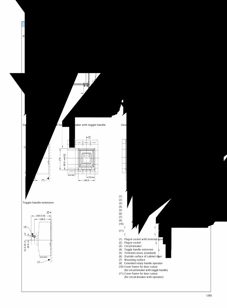
1/99
3VL630 断路器3VL630 Circuit-Breakers 1
(9)
(9)
CL
(5)
(3) (2)
(7)
(1)
X
(6)
Z
300 MAX - 60 MIN
1.5 - 4
0.5
22.5
101
40
103.5205
83.5
270
290593 MAX - 353 MIN
NS
K-8
816
(6)
(7)
(10)
X
Z
X
Y
70.51 - 3
120106.5
175
95.5
140.5
NSK-8817
Y(11)
X
268.5
139.5
98.5
247.
5
TRIPPED
NS
K-8
818
(7)
(4)
Z
138.5
164.5 (4)
41.5
(4)
34.5
NSK-8819
附件 Accessories
加长旋转操作机构
Extended rotary handle operator
带扳动手柄及面框的断路器的柜门开孔
Cover frame for door cutout for circuit-breaker with toggle handle
扳动手柄加长件
Toggle handle extension
带操作机构及面框的断路器的柜门开孔
Cover frame for door cutout for circuit-breaker with operator
(1) 带端子盖的插入式插座(2) 插入式插座(3) 断路器(4) 扳动手柄加长件(5) 端子盖(标准)(6) 柜门外表面(7) 安装表面(9) 加长旋转手柄操作机构(10) 柜门开孔面框
(用于带扳动手柄的断路器)(11) 柜门开孔面框
(用于带操作机构的断路器)
(1) Plug-in socket with terminal covers(2) Plug-in socket(3) Circuit-breaker(4) Toggle handle extension(5) Terminal covers (standard)(6) Outside surface of cabinet door(7) Mounting surface(9) Extended rotary handle operator(10) Cover frame for door cutout
(for circuit-breaker with toggle handle)(11) Cover frame for door cutout
(for circuit-breaker with operator)
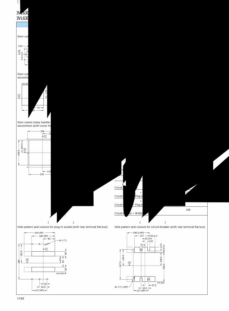
1/100
3VL630 断路器3VL630 Circuit-Breakers
X
Y
0.5
64
44
4488
7
885.5 4X
NSK-8820
X
Y
18291
110
165.
5
NSK-8821
X
Y
256
226
209.
510
4.5
3.5
133
113
235
2
117.
522
2
5.5
13.1
NSK-8822a
6x
X
Y
244 (4P)
63.5127 (4P)
180 (3P)
155.
528
9
92
32
57
38
90
38
NSE-00569
7.14x
37.575
8442
NSK-8824Y
X
65
61
129.5
73.5
164
122
7114
2
5.5
NSK-8825a
X
4X
Y
X
44.5
247.
513
4.5
127 (4P)63.5
41.5
190.5 (4P)
22
127
31.5
12.5
108.
523
9.5
44.5
7.1 (4P)4x
Y
NSK-8826
P Y
D
NSK-8786
面板开孔 Panel cutouts
加长旋转操作机构的门开孔
Door cutout extended handle rotary operator
旋转操作机构、储能操作机构和加长框的门开孔 (不带面框)
Door cutout rotary handle operator, stored energy operator and extendedescutcheon (without cover frame)
旋转操作机构、储能操作机构和加长框的门开孔 (带面框)
Door cutout rotary handle operator, stored energy operator and extendedescutcheon (with cover frame)
插入式插座的孔型和开孔 (带扁平母排背后端子)
Hole pattern and cutouts for plug-in socket (with rear terminal flat bus)
断路器的扳动手柄门开孔 (不带面框)
Door cutout toggle operator (without cover frame)
断路器的扳动手柄门开孔 (带面框)
Door cutout toggle operator (with cover frame)
断路器的孔型和开孔 (带扁平母排背后端子)
Hole pattern and cutouts for circuit-breaker (with rear terminal flat bus)
注: 门开孔要求在基准轴Y和门铰链之间的最小间隔。
Note: Door cutouts require aminimum distancebetween datum Y and thedoor hinge.
门铰链点Door HingePoint
A
仅有断路器 150Circuit-breaker only
断路器 + 插入式插座 + 储能操作机构 150Circuit-breaker + Plug-in socket + Stored energy operator
断路器 + 插入式插座 + 旋转手柄 200Circuit-breaker + Plug-in socket + Rotary handle
断路器 + 抽出式装置 200Circuit-breaker + Withdraw device
D > 表中的 A + (P x 5)
D > A from table + (P x 5)
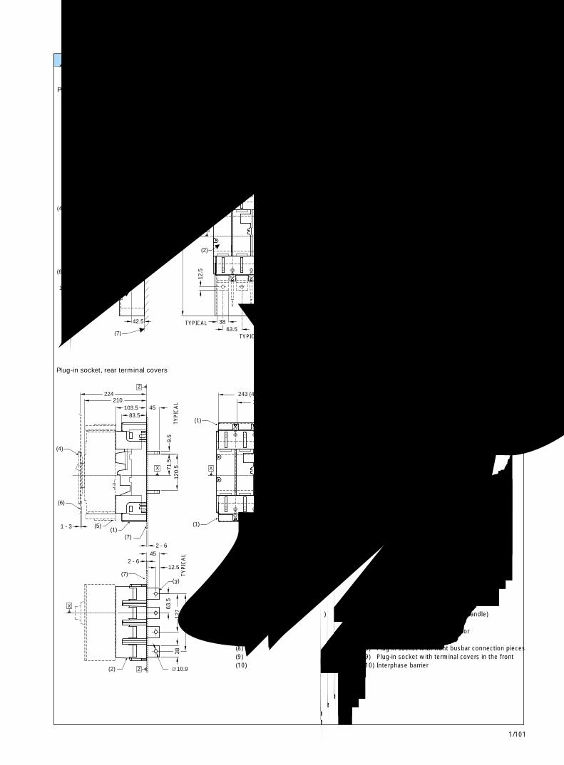
1/101
3VL630 断路器3VL630 Circuit-Breakers 1
(7)
(4)
(6)
(5)
(8)
(2)
(9)
Z
(2)
(10)
(9)
(9)
(8)
103.5
1 - 3
42.5
210
224
83.5
552
(9)
63.5
12.5
38 63.5
262
(10)28
7
243 (4P)180 (3P)
32
90
7.1 (3P)
502
(10)
358
10.919
0
155.
5
63.5 127 (4P)
32
289 X X
Y
4X7.1 (4P)6X
Y
X
NSK-8829
(7)
(7)
(2)
(6)
(4)
(5)(1)
(1)
(1)
(2)
253.5 (4P)
103.5
2 - 6
1 - 3
210 224
38
12.5
45
63.5
127
190.
5
120.
5
10.9
71.5
2 - 6
83.5
9.5
45
243 (4P)180 (3P)
90
289
330
176
63.5
155.
5
63.5 63.5
190 (3P)95
321.
5 17
1.5
Z
X
Y
X X
Y
Z
X
NSK-8830a
插入式插座和附件 Plug-in socket and accessories
带正面接线端子盖的插入式插座
Plug-in socket with terminal covers in the front
带背后端子盖的插入式插座
Plug-in socket, rear terminal covers
带正面母排连接件的插入式插座的孔型
Plug-in socket hole pattern front busbar connection pieces
插入式插座
Plug-in socket
(1) 带背后端子盖的插入式插座(2) 插入式插座(3) 带扁平母排背后端子的插入式插座(4) 柜门开孔面框
(用于带扳动手柄的断路器)(5) 端子盖(标准)(6) 柜门外表面(7) 安装表面(8) 带正面母排连接件的插入式插座(9) 带正面接线端子盖的插入式插座(10) 相间隔板
(1) Plug-in socket with rear terminal covers(2) Plug-in socket(3) Plug-in socket with rear terminals flat bus(4) Cover frame for door cutout
(for circuit-breaker with toggle handle)(5) Terminal covers (standard)(6) Outside surface of cabinet door(7) Mounting surface(8) Plug-in socket with front busbar connection pieces(9) Plug-in socket with terminal covers in the front(10) Interphase barrier
典型
TYPICAL
典型 TYPICAL
典型 TYPICAL
典型
TY
PIC
AL
典型
TY
PIC
AL

1/102
3VL630 断路器3VL630 Circuit-Breakers
(10)
(6)
(11)
(9)
(4)
(7)
(1)(5)
Z
1 -3
337.5
148
251.5
266
X
NS
K-8
831
(4)
(6)
(9)
(10)(11) (5) (1)
(7)
1 - 3
148
293
27
365
251.5
X
Z
NS
K-8
832
(8)
(4)
(6) (11)
(10) (7)(5)(1)
362
1 - 3
122
327.5 224
X
Z
NS
K-8
833
(4)
(6)
(8)
(11)
(10) (5)(7)
(1)1 - 3
389
224 197
95 27
327.5
Z
X
NS
K-8
834
抽屉型和附件 Drawout version and accessories
带有抽出式装置和旋转操作机构的 3VL630断路器 (运行位置)
3VL630 circuit-breaker with rotary operator mounted in withdraw device(engaged position)
带有抽出式装置和储能操作机构的 3VL630断路器 (运行位置)
3VL630 circuit-breaker with stored energy operator mounted inwithdraw device (engaged position)
(1) 带端子盖的插入式插座(4) 柜门开孔面框
(用于带操作机构的断路器)(5) 端子盖(标准)(6) 柜门外表面(7) 安装表面(8) 储能操作机构(9) 旋转手柄操作机构(10) 抽出式装置(11) 抽出式曲柄位置
带有抽出式装置和旋转操作机构的 3VL630断路器 (断开位置)
3VL630 circuit-breaker with rotary operator mounted in withdraw device(disengaged position)
带有抽出式装置和储能操作机构的 3VL630断路器 (断开位置)
3VL630 circuit-breaker with stored energy operator mounted inwithdraw device (disengaged position)
(1) Plug-in socket with terminal covers(4) Cover frame for door cutout
(for circuit-breaker with operator)(5) Terminal covers (standard)(6) Outside surface of cabinet door(7) Mounting surface(8) Stored energy operator(9) Rotary handle operator(10) Withdraw device(11) Withdraw crank location
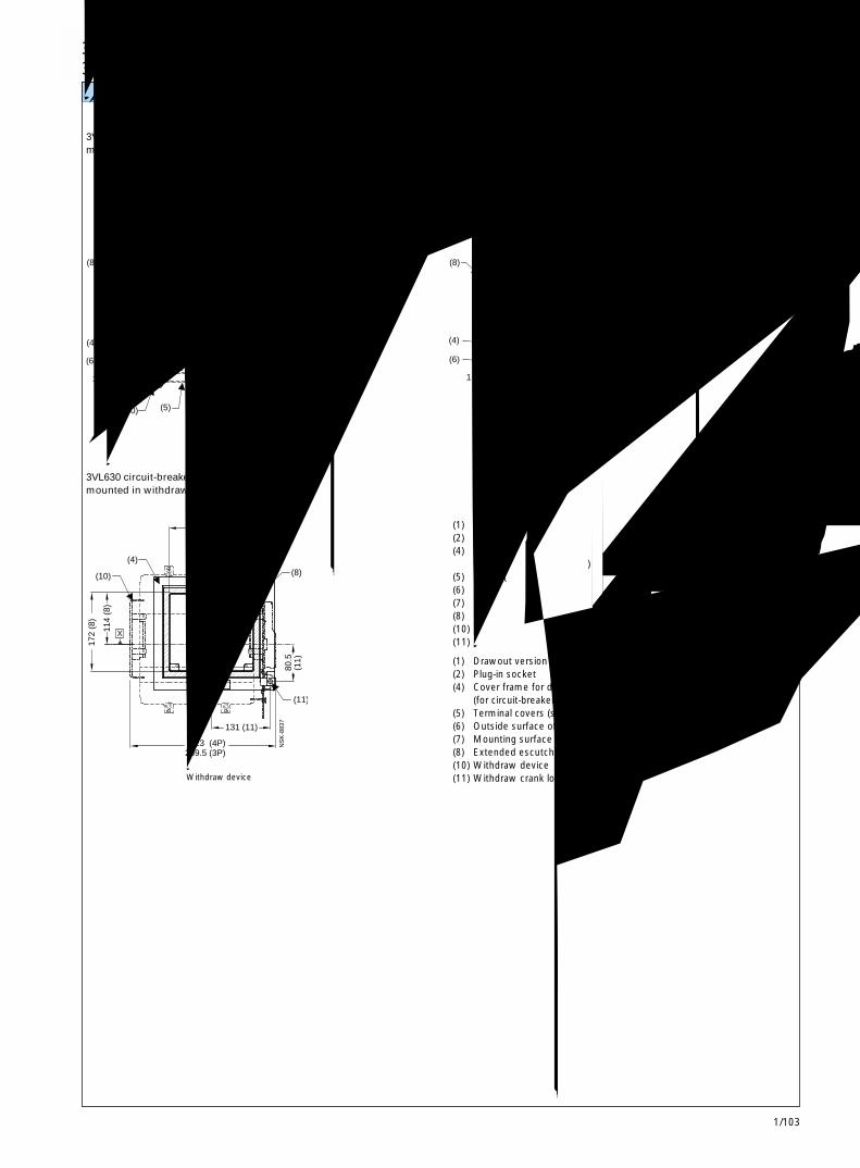
1/103
3VL800断路器3VL800 Circuit-Breakers 1
抽屉型和附件 Drawout version and accessories
带有抽出式装置和加长框的 3VL630断路器(运行位置)
3VL630 circuit-breaker with extended escutcheonmounted in withdraw device (engaged position)
带有抽出式装置和加长框的 3VL630断路器(断开位置)
3VL630 circuit-breaker with extended escutcheonmounted in withdraw device (disengaged position)
带有抽出式装置和加长框的 3VL630 断路器
3VL630 circuit-breaker with extended escutcheonmounted in withdraw device
(1) 带端子盖的抽出式(2) 插入式插座(4) 柜门开孔面框
(用于带操作机构的断路器)(5) 端子盖(标准)(6) 柜门外表面(7) 安装表面(8) 加长框(10) 抽出式装置(11) 抽出式曲柄位置
(1) Drawout version with terminal covers(2) Plug-in socket(4) Cover frame for door cutout
(for circuit-breaker with operator)(5) Terminal covers (standard)(6) Outside surface of cabinet door(7) Mounting surface(8) Extended escutcheon(10) Withdraw device(11) Withdraw crank location
抽出式装置Withdraw device
3VL630断路器3VL630 Circuit-Breakers
NS
K-8
836
Z
X
(4)
(6)
(8)
(10)
(11) (5)(7)
(1)
1 - 3
251.5
19148
289.5
27
Y
X
NS
K-8
837
(11)
(10)
(4)
(8)
323 (4P)259.5 (3P)
172
(8)
114
(8)
131 (11)
189 (8)94.5 (8)
80.5
(1
1)
Z
X
NS
K-8
835
(11)
(6)
(4)
(10)
(8)
(1)
(5) (7)
(2)
262.5
148
1 - 3
46
251.5
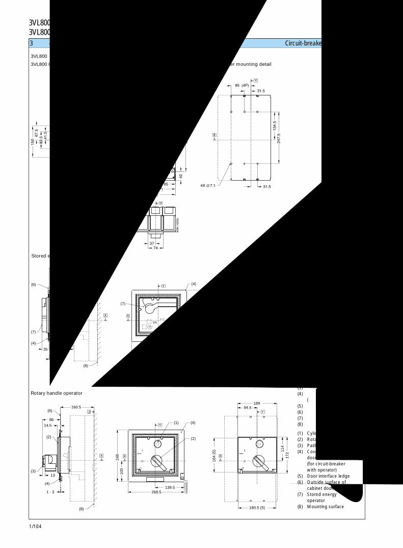
1/104
3VL800断路器3VL800 Circuit-Breakers3 极和 4 极断路器 Circuit-breakers, 3- and 4-pole
(1) 柱形锁(2) 旋转手柄(3) 挂锁钩(4) 柜门开孔面框
(用于带操作机构的断路器)(5) 门接口凸缘(6) 柜门外表面(7) 储能操作机构(8) 安装表面
(1) Cylinder lock(2) Rotary handle(3) Padlock hook(4) Cover frame for
door cutout(for circuit-breakerwith operator)
(5) Door interface ledge(6) Outside surface of
cabinet door(7) Stored energy
operator(8) Mounting surface
3VL800断路器
3VL800 Circuit-Breakers
储能操作机构
Stored energy operator
旋转操作机构
Rotary handle operator
断路器安装详图
Circuit-breaker mounting detail
4X
Z
X
114.5
119
151.5
17.5
82.5
67.5
150 41.5
16
12895 (4P)
74
190 (3P)
253.5 (4P)
37
5842
42 58
406.5
213.5
127 (4P)
63.5
171.5
16.5
32.5
42
95
63.5
322.5
31.5
134.5
31.5
247.5
Y
9
X X
7.1
Y
Y
NSK-1000b
50
(4)
(7)
(6)
(8)
(7)
(1)
(4)
35 117.5
1 - 3
236.5 189
180.5 (5)
268.5 139.5
100
248
164
(5)
94.5
114
172
ON/OFFON
Z
X X
Y
X
Y
NSE00816
(4)
(3)
(2)
(6)
(8)
(1)
(2)
(4)
160.5
14.5
1 - 3
86
13
189
180.5 (5)
268.5
100
248
139.5
164
(5)
94.5
114
172
Y
XX
Y
X
Z
NS
E00
817
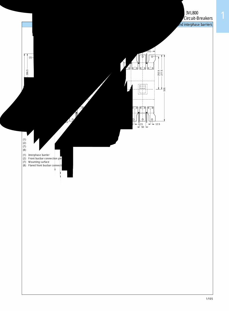
1/105
3VL800断路器3VL800 Circuit-Breakers 1
连接件和相间隔板 Connections and interphase barriers
(1) 相间隔板(2) 正面母排连接件(7) 安装表面(8) 扩口正面母排连接件
(1) Interphase barrier(2) Front busbar connection pieces(7) Mounting surface(8) Flared front busbar connection pieces
(7)
(2)
(1)
Z
(2)
(8)
(1) (1)33.5
552.
5
9.5
286.
5
97.5 119
50 25
25 25
ÿ 1312.5
50
277.
5 53
5
63.5 63.5
252.
548
5
485
76
278 (4P)
202 (3P)
101
535
12.5
252.
527
7.5
X
Y63.5(4P)
ÿ 13
Y
X X
NSE00876
典型TYPICAL
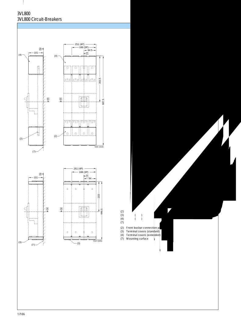
1/106
3VL800断路器3VL800 Circuit-Breakers
(2)
(7)
(4)
Z
(2)
(4)101
687.
5
251 (4P)188 (3P)
94.5
353.
5
X X
Y
NSK-1004b
(3)(7 ) (3)
101
251 (4P)
188 (3P)
94
233
446.
5
ZY
X X
NSK-1005a
端子盖 Terminal covers
(2) 正面母排连接件(3) 端子盖(标准)(4) 端子盖(加长)(7) 安装表面
(2) Front busbar connection pieces(3) Terminal covers (standard)(4) Terminal covers (extended)(7) Mounting surface
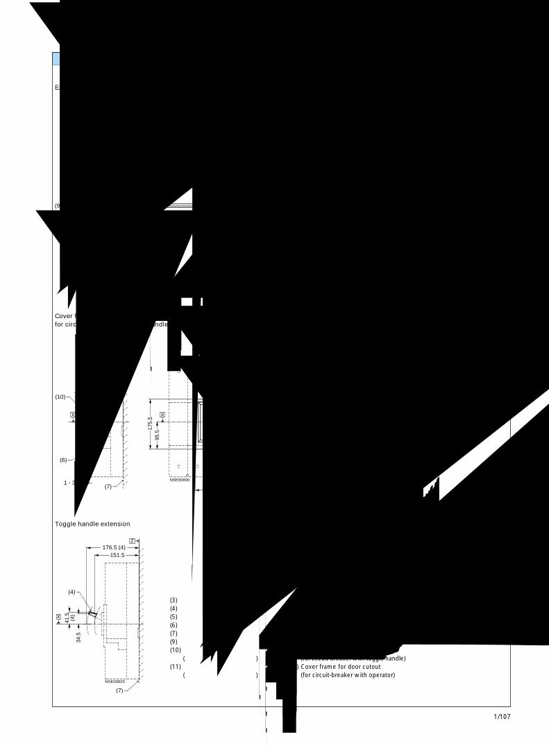
1/107
3VL800断路器3VL800 Circuit-Breakers 1
(9)
(9) CL
(6)
(5) (7)
(3)
Z503 MAX - 263 MIN
0.5
101
1.5 - 4
22.5
300 MAX - 60 MIN
40
114.5 179
199
X
NS
K-1
006
(7)
(6)
(10) (10)
1 - 3
119
132.5
140.5 70.5
175.
595
.5
XX
Y
Z
NSE00800
(4)
(7)
Z
34.5
151.5 176.5 (4)
NSE00820
X
41.5
(4)
(11)
268.5
139.5
100
248
Y
X
NS
E00
819
附件 Accessories
(3) 断路器(4) 加长扳动手柄(5) 端子盖(标准)(6) 柜门外表面(7) 安装表面(9) 加长旋转手柄操作机构(10) 柜门开孔面框
(用于带扳动手柄的断路器)(11) 柜门开孔面框
(用于带操作机构的断路器)
加长旋柄操作机构
Extended rotary handle operator
带扳动手柄及面框的断路器的柜门开孔
Cover frame for door cutoutfor circuit-breaker with toggle handle
加长扳动手柄
Toggle handle extension
带操作机构及面框的断路器的柜门开孔
Cover frame for door cutoutfor circuit-breaker with operator
(3) Circuit-breaker(4) Toggle handle extension(5) Terminal covers (standard)(6) Outside surface of cabinet door(7) Mounting surface(9) Extended rotary handle operator(10) Cover frame for door cutout
(for circuit-breaker with toggle handle)(11) Cover frame for door cutout
(for circuit-breaker with operator)
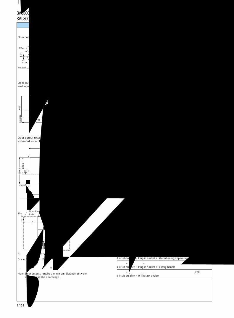
1/108
3VL800断路器3VL800 Circuit-Breakers
Y88
64
0.5
7
44 88
44
5.54X
X
NSK-1009
3876
42 84
Y
X
NSE0082211
0
91 182
165.
5
X
Y
NS
K-1
011
7173.5
16
4
65
61
129.5
122
142
Y
X
4X 5.5
NSK-1012a
113 226
132.
520
9.5
256
152.5
133
235
24.5
142
194
Y6 x 5.5
13.1
X
NSE00825
P Y
D
NSK-8786
面板开孔 Panel cutouts
注: 门开孔要求在基准轴 Y 和门铰链之间的最小间隔。
Note: Door cutouts require a minimum distance betweendatum Y and the door hinge.
加长旋转操作机构的门开孔
Door cutout extended handle rotary operator
旋转操作机构、储能操作机构和加长框的门开孔 (不带面框)
Door cutout rotary handle operator, stored energy operatorand extended escutcheon (without cover frame)
旋转操作机构、储能操作机构和加长框的门开孔(带面框)
Door cutout rotary handle operator, stored energy operator andextended escutcheon (with cover frame)
门铰链点Door HingePoint
断路器的扳动手柄门开孔 (不带面框)
Door cutout toggle operator (without cover frame)
断路器的扳动手柄门开孔 (带面框)
Door cutout toggle operator (with cover frame)
A
仅有断路器 150Circuit-breaker only
断路器 + 插入式插座 + 储能操作机构 150Circuit-breaker + Plug-in socket + Stored energy operator
断路器 + 插入式插座 + 旋转手柄 200Circuit-breaker + Plug-in socket + Rotary handle
断路器 + 抽出式装置 200Circuit-breaker + Withdraw device
D > 表中的 A + (P x 5)
D > A from table + (P x 5)
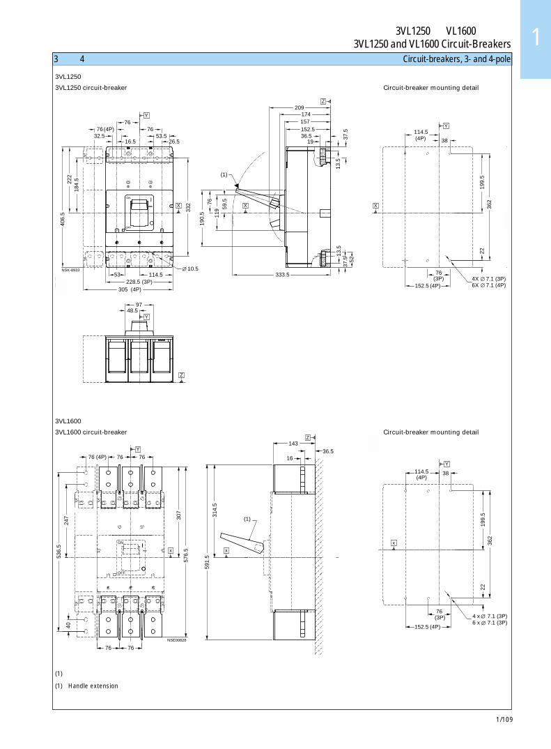
1/109
3VL1250 和 VL1600断路器3VL1250 and VL1600 Circuit-Breakers 1
(1)
333.5 228.5 (3P)
97
406.
5
305 (4P)
48.5
53
222
184.
5
114.5
332
190.
5
59.5
11
9 76
32.5 76 (4P)
16.5
76
26.5
76 53.5 37
.513
.5
52
13.5
37
.5
152.5 36.5
19
157
209 174
II
ION
OOFF
P)P)
10.5
Y
X X
Z
Y
Z
NSK-8933
(1)
76
536.
5
40
247
576.
5 30
7
591.
531
4.5
76 (4P) 76 76 1636.5
143
OO
I
OFF
ONII
Y
76
x x
Z
NSE00828
3极和 4极断路器 Circuit-breakers, 3- and 4-pole
3VL1250断路器
3VL1250 circuit-breaker
3VL1600断路器
3VL1600 circuit-breaker
152.5 (4P)
76 (3P)
114.5 (4P) 38
406
5
4X
22
199.
5 36
2
Y
X
7.1 (3P)6X 7.1 (4P)
152.5 (4P)
76 (3P)
2219
9.5
362
114.5 (4P)
38
5
Y
4 x 7.1 (3P)6 x 7.1 (3P)
x
(1) 加长手柄
(1) Handle extension
断路器安装详图
Circuit-breaker mounting detail
断路器安装详图
Circuit-breaker mounting detail
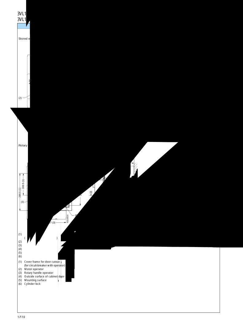
1/110
3VL1250 和 VL1600断路器3VL1250 and VL1600 Circuit-Breakers
(2)
(6)
(1)
(2)
(1)
(4)
(5)
Z
227 (2)
212
(2)
134
(2)
12.5
1-3
298
152.5
179356.5
155.5Y
X X
NS
E00
829
(3)
(6)
(1)
(4)
(1)
(5)
(3)
169.
5 (1
)28
9.5
(1)
227 (3)
161 (1)
310 (1)
134
(3)
212
(3)
1-3
236 336.5
152.5
221.5
Y
X X
Z
NS
E00
830
操作机构 Operators
旋转操作机构
Rotary handle operator
储能操作机构
Stored energy operator
(1) 柜门开孔面框(用于带操作机构的断路器)
(2) 电动机操作机构(3) 旋转操作机构(4) 柜门外表面(5) 安装表面(6) 柱形锁
(1) Cover frame for door cutout(for circuit-breaker with operator)
(2) Motor operator(3) Rotary handle operator(4) Outside surface of cabinet door(5) Mounting surface(6) Cylinder lock
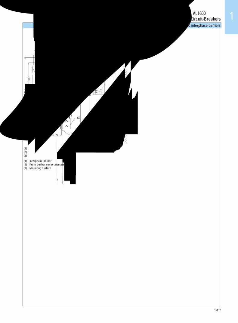
1/111
3VL1250 和 VL1600断路器3VL1250 and VL1600 Circuit-Breakers 1
(1)
(2)
(1)
(3)
(2)
Y
40
536.
5
247
76 (4P) 16
76
307
576.
5
591.
5 31
4.5
76 36.5143
OO
I
OFF
ONII
76
X
76
X
Z
NSE00867
13
60
连接件和相间隔板 Connections and interphase barriers
(1) 相间隔板(2) 正面母排连接件(3) 安装表面
(1) Interphase barrier(2) Front busbar connection pieces(3) Mounting surface
典型TYPICAL
典型TYPICAL
典型
TY
PIC
AL

1/112
3VL1250 和 VL1600断路器3VL1250 and VL1600 Circuit-Breakers
(3)
(1)
(3)
(1)
X
(4)
304.5 (4P)228 (3P)
114
688.
536
2.5
152
1636.5
OO
I
OFF
ONII
Y
Z
X
NSE00868
(2) (2) (4)
446.
5 24
2
300 (4P)224 (3P) 112
152
OO
I
OFF
ON II
Y
X
Z
X
NSK-8937
端子盖 Terminal covers
仅限 3VL1250断路器
3VL1250 circuit-breaker only
(1) 正面母排连接件(2) 端子盖(短) -
仅用于 3VL1250断路器(3) 端子盖(加长)(4) 安装表面
(1) Front busbar connection pieces(2) Terminal covers (short) -
only for 3VL1250 circuit-breaker(3) Terminal covers (extended)(4) Mounting surface
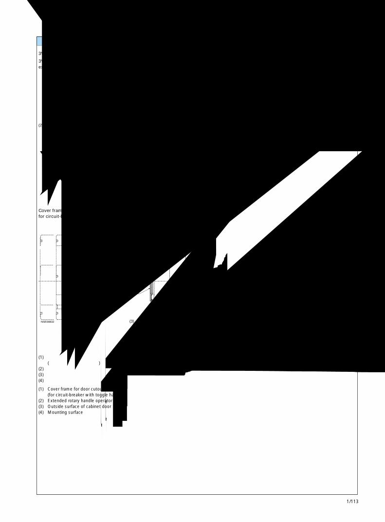
1/113
3VL1250 和 VL1600断路器3VL1250 and VL1600 Circuit-Breakers 1
(2)
(3)
CL
(2)
(4)
40.5
137.
5
22
101
22.5
77.5
300 MAX - 60 MIN
40
256
152.5
241.5
1-3
Z
X
NSE00831
(3)
(1)
(1)
(4)
70.5140.5
8017
5.5
152.5 169
1-3
OO
I
OFF
ONII
Y
X
Z
X
NSE00832
附件 Accessories
(1) 柜门开孔面框(用于带扳动手柄的断路器)
(2) 加长旋转操作机构(3) 柜门外表面(4) 安装表面
(1) Cover frame for door cutout(for circuit-breaker with toggle handle)
(2) Extended rotary handle operator(3) Outside surface of cabinet door(4) Mounting surface
3VL1250断路器加长旋转操作机构
3VL1250 circuit-breaker rotary handle operatorextended handle
带扳动手柄及面框的断路器的柜门开孔
Cover frame for door cutoutfor circuit-breaker with toggle handle
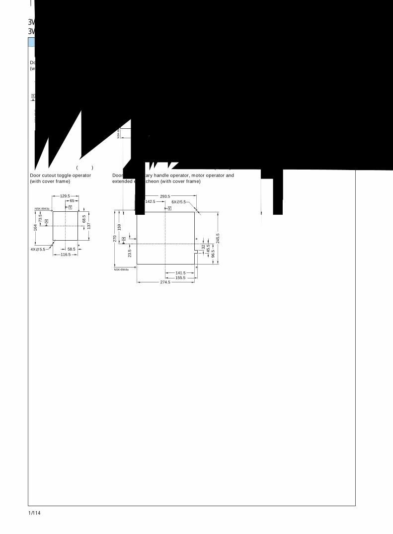
1/114
3VL1250 和 VL1600断路器3VL1250 and VL1600 Circuit-Breakers
50 100
61
122
Y
X
NS
K-8
940 20
4
220 110
128.
5
NS
K-8
941
X
Y
77.5
88 44
4X
88
44
NSK-8942
Y
64
X
575.5
5.5
73.5
16
4
58.5 116.5
129.5
68.5
137
65
NSK-8943a
X
4X
Y
270
23.5
159
274.5 155.5 141.5
245.
5 96
.5 32
45.5
6X142.5 293.5
X
Y
5.5
NSK-8944a
面板开孔 Panel cutouts
旋转操作机构、电动机操作机构和加长框的门开孔(带面框)
Door cutout rotary handle operator, motor operator andextended escutcheon (with cover frame)
扳动操作机构的门开孔(不带面框)
Door cutout toggle operator(without cover frame)
扳动操作机构的门开孔(带面框)
Door cutout toggle operator(with cover frame)
旋转操作机构和电动机操作机构的门开孔 (不带面框)
Door cutout rotary handle operator and motor operator(without cover frame)
加长旋转操作机构的门开孔
Extended handle rotary operator door cutout
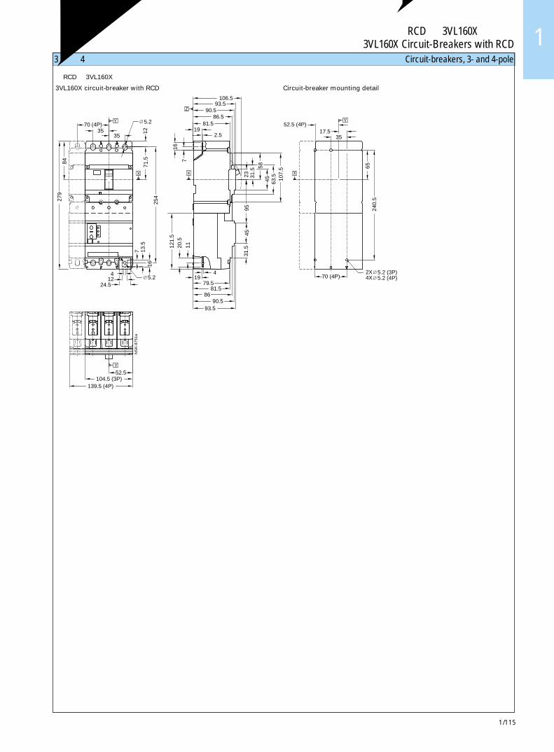
1/115
带 RCD 的 3VL160X 断路器3VL160X Circuit-Breakers with RCD 1
45
31.5
19 4
86
79.5 81.5
90.5 93.5
11
121.
5 20
.5
16
13.5
7
24.5 12 4
52.5 104.5 (3P)
139.5 (4P)
Y
70 (4P) 5.2 (4P)4X 5.2 (3P)2X
52.5 (4P)
58
31.5
106.5
90.5 93.5
81.5 86.5
2.5 19 12
35
107.
5 63
.5
45 23
95
7
16
71.5
254
84
279
70 (4P)
Z
Y
XX
35
240.
5 65
17.5
Y5.2
NS
K-8
751a
35
5.2
X
3极和 4极断路器 Circuit-breakers, 3- and 4-pole
带RCD的 3VL160X断路器
3VL160X circuit-breaker with RCD
断路器安装详图
Circuit-breaker mounting detail
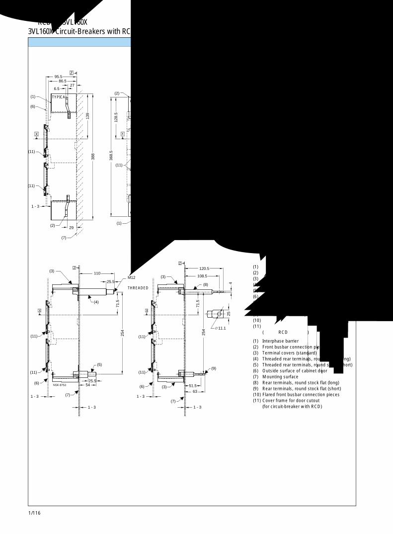
1/116
带 RCD 的 3VL160X 断路器3VL160X Circuit-Breakers with RCD
(11)
343
74.5 148.5
35
102.
5
1 - 3
29 (1)
(11)
(7)
(2)
(11)
368.
5
20
102.
5
(10)(1)
35 35 70 (4P)
116
73
128.
5 36
8.5
45
86.5 95.5
6.5 13
9 38
8
27 Y
(2)
X
(1)
(6)
X
(11)
116
343
44.5(4P)
128.
5 73
XION
OOFF
ION
OOFF
NSK-8752a
7.17.1
Z
Y
44.5 44.5
51.5
108.5
120.5
71.5
71.5
1 - 3
63
25.5
1 - 3
254
254
54
1 - 3
1 - 3
25.5
110
Z
X
M12
Z
X
(6)
(7)
(9)
(8)
(6)
(7)
(3)
(3)
(3)
(11)
(11)
(11)
(11)
(5)
(4)
4 25
NSK-8753
11.1
典型TYPICAL
典型 TYPICAL
典型 TYPICAL
带螺纹THREADED
连接件和相间隔板 Connections and interphase barriers
(1) 相间隔板(2) 正面母排连接件(3) 端子盖(标准)(4) 带螺纹的背面端子,圆杆(长)(5) 带螺纹的背面端子,圆杆(短)(6) 柜门外表面(7) 安装表面(8) 背面端子,扁平圆杆(长)(9) 背面端子,扁平圆杆(短)(10) 扩口正面母排连接件(11) 柜门开孔面框
(用于带 RCD 的断路器)
(1) Interphase barrier(2) Front busbar connection pieces(3) Terminal covers (standard)(4) Threaded rear terminals, round stock (long)(5) Threaded rear terminals, round stock (short)(6) Outside surface of cabinet door(7) Mounting surface(8) Rear terminals, round stock flat (long)(9) Rear terminals, round stock flat (short)(10) Flared front busbar connection pieces(11) Cover frame for door cutout
(for circuit-breaker with RCD)
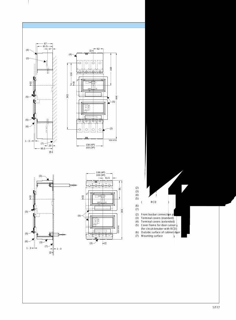
1/117
带 RCD 的 3VL160X 断路器3VL160X Circuit-Breakers with RCD 1
343
(5)
95.5
1 - 3
29(7)
z
(5)
(6)
116
87 81.5
27
(4)
(2)
(4)
X
444
103 (3P)138 (4P)
(5)
(2)
52
168
x
Y
ION
OOFF
NSK-8754
1 - 3 1 - 3
X
z
(5)
(5)
(5)
(3)
(7)
(6)
(3)
96
51.5 103 (3P)138 (4P)
303
X
Y(3)
ION
OOFF
NS
K-8
755
端子盖 Terminal covers
(2) 正面母排连接件(3) 端子盖(标准)(4) 端子盖(加长)(5) 柜门开孔面框
(用于带 RCD 的断路器)(6) 柜门外表面(7) 安装表面
(2) Front busbar connection pieces(3) Terminal covers (standard)(4) Terminal covers (extended)(5) Cover frame for door cutout
(for circuit-breaker with RCD)(6) Outside surface of cabinet door(7) Mounting surface
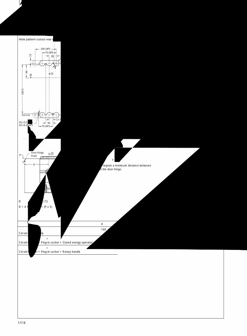
1/118
带 RCD 的 3VL160X 断路器3VL160X Circuit-Breakers with RCD
48
54 107.5
48
24.5
93
Y
X
NS
K-8
760
254
17.5 35
70 (4P)4X 5.2 (4P)2X 5.2 (3P)
6X 26 (3P) 8X 26 (4P)
71.5
105 (4P)
70 (3P)
13
65
240.
5
35
YX
NSK-8758
∅∅
71
128
90
8X 5.5 64
R3.0
71
82
136
38.5
79
.5
90
68
Y
X
NS
K-8
759a
36
P Y
D
NSK-8786
面板开孔 Panel cutouts
门铰链点Door HingePoint
D > 表中的 A + (P ( 5)
D > A from table + (P x 5)
注: 门开孔要求在基准轴 Y 和门铰链之间的最小间隔。
Note: Door cutouts require a minimum distance betweendatum Y and the door hinge.
A
仅有断路器 100Circuit-breaker only
断路器 + 插入式插座 + 储能操作机构 100Circuit-breaker + Plug-in socket + Stored energy operator
断路器 + 插入式插座 + 旋转手柄 200Circuit-breaker + Plug-in socket + Rotary handle
圆杆背面端子的孔型和开孔
Hole pattern cutout rear terminals, round stock
断路器的扳动手柄门开孔(带面框)
Door cutout toggle operator (with cover frame)
断路器的扳动手柄门开孔(不带面框)
Door cutout toggle operator(without cover frame)
典型TYPICAL
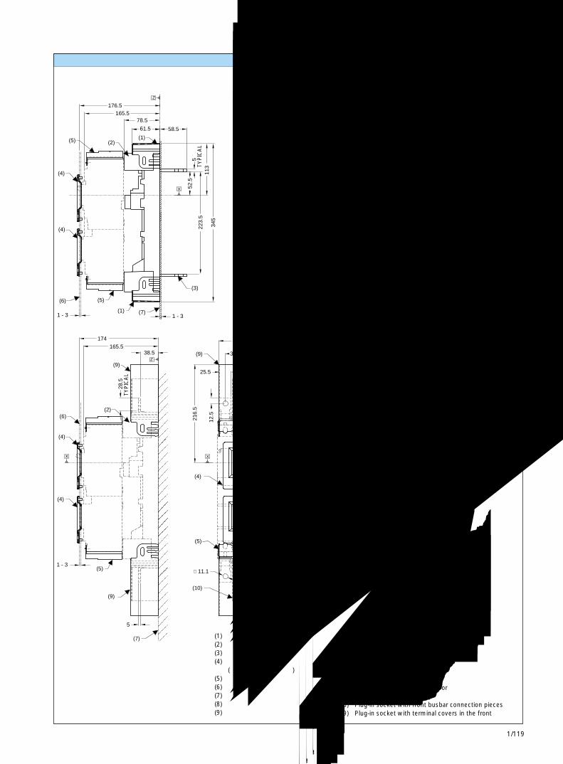
1/119
带 RCD 的 3VL160X 断路器3VL160X Circuit-Breakers with RCD 1
6X 5.2 (4P)4X 5.2 (3P)
1 -
3(2)
1 - 31 - 3 Y
(3)
(7)
(5)(6)
(1)
50 100 (3P)135 (4P)
315
45.5
35 35
12.5
70 (4P)
58.5
5
78.5
61.5
11.1
25.5
345
52.5
223.
5 11
3
176.5 165.5 Y
(3)
(1)
(2)
Z
(1)
X
(2)(5)
(4)
(4)
38
38
70 (4P)35
17.5
190
35.5
65
98
130 (3P)165 (4P)
YX
NSK-8756
Z
6X 5.2 (4P)4X 5.2 (3P)
50 17.5
135 (4P)
130.
5
379
551
35
12.5
25.5
216.
5
38.5
5
174
1 - 3
28.5
165.5
(8)
Y
(4)
(9)
(9)
(4)
Z
(5)
(10)
(7)
(9)
(6)
(4)
x
(2)
(4)
(9)
(5)
70 (4P)35
98
17.5
315
Y
XION
OOFF
11.1
∅
NSK-8757
X
插入式插座和附件 Plug-in socket and accessories
带扁平母排背后端子的插入式插座的孔型和开孔
Hole pattern and cutout for plug-in socketwith rear terminals flat bus
带正面母排连接件的插入式插座的孔型
Hole pattern for plug-in socketwith front busbar connection pieces
(1) 带背后端子盖的插入式插座(2) 带 RCD 的断路器的插入式插座(3) 带扁平母排背后端子的插入式插座(4) 柜门开孔面框
(用于带 RCD 的断路器)(5) 端子盖(标准)(6) 柜门外表面(7) 安装表面(8) 带正面母排连接件的插入式插座(9) 带正面连接端子盖的插入式插座
(1) Plug-in socket with rear terminal covers(2) Plug-in socket for circuit-breaker with RCD(3) Plug-in socket with rear terminals flat bus(4) Cover frame for door cutout
(for circuit-breaker with RCD)(5) Terminal cover (standard)(6) Outside surface of cabinet door(7) Mounting surface(8) Plug-in socket with front busbar connection pieces(9) Plug-in socket with terminal covers in the front
典型TYPICAL
典型
TYP
ICA
L
典型 TYPICAL
典型
TYP
ICA
L
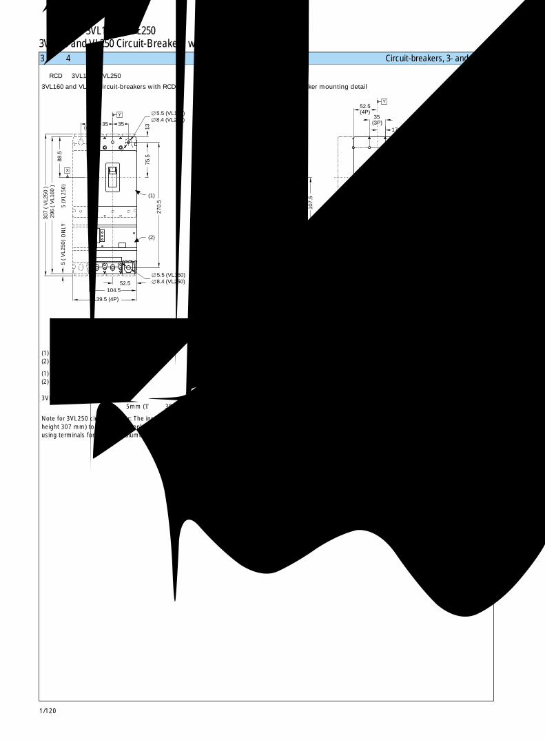
1/120
带 RCD的 3VL160和 VL250断路器3VL160 and VL250 Circuit-Breakers with RCD
(2)
(1)
Y
(2)
(1)
8.4 (VL250)
5 (
VL2
50)
139.5 (4P)
104.5 52.5
88.5
29
6 (
VL1
60 )
307
( V
L250
)
270.
5
35
13
75.5
35
31.5
121.
5 24
19
86
81.5
4
90.5 93.5
70 (4P)
2.5 (160A)4.0 (250A)
11
24
11
45
107.
5
58
63.5
31
.5
19
120
87 90.5 106.5
253
65
17.5
35(3P)35
(4P)
5.5 (VL160)
X
8.4 (VL250)5.5 (VL160)
X
ZY
52.5(4P)
X
5.2 (4P)5.2 (3P)2X
4X
NS
K-8
788
3极和 4极断路器 Circuit-breakers, 3- and 4-poleO
NLY
仅限
5 (V
L250
)
(1) 断路器(2) RCD(剩余电流装置)
(1) Circuit-breaker(2) RCD (residual current device)
3VL250断路器注释:只有当使用铜或铝电缆端子时,才可在该型号断路器的任何一端增加 5mm (总高度 307mm)。
Note for 3VL250 circuit-breaker: The increase of 5 mm (totalheight 307 mm) to either end is only applicable whenusing terminals for copper or aluminium cable.
带RCD的 3VL160和 VL250断路器
3VL160 and VL250 circuit-breakers with RCD
断路器安装详图
Circuit-breaker mounting detail
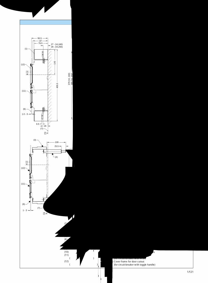
1/121
带 RCD的 3VL160和 VL250断路器3VL160 and VL250 Circuit-Breakers with RCD 1
(6)
(1)
(11)
(1)
(11)
(12)
(1) (2)
(12)
(10)
(11)
(12)
6.5
1.0 - 3
29
102.
5
35 51
27 - (VL160)29 - (VL250)
405.
5 85.5
143
133
87 95.5
79.5
44.5(4P)
35
359.
5
61.5
138.
5
35 ∅
120
385
(VL
250)
44.5
359.
5
120 13
3
X
Z
(7)
11.1 (VL 250)
Y35
(4P)
X
NSK-8789b
X
7 (VL 160)∅44.5 ∅ 11.1 (VL 250)
7 (VL 160)∅
22 (VL 250) 20 (VL 160)
379
(VL
160)
385
(VL
250)
37
9 (V
L 16
0)
Y
( M12 )
1 - 31 - 3 1 - 3
25.5 53.5
631 - 3
51.5
270.
5
109
25.5
11
270.
5 120.5
108.5
254
(11)(11)
(6)
(7)
(5)
(7)
(6)
(9 )
(12)(12)
(3)
(4)
(3)
(8)
X
Z Z
X
NSK-8790
连接件和相间隔板 Connections and interphase barriers
(1) 相间隔板(2) 正面母排连接件(3) 端子盖(标准)(4) 背后端子,圆杆(长)(5) 背后端子,圆杆(短)(6) 柜门外表面(7) 安装表面(8) 背后端子,扁平圆杆(长)(9) 背后端子,扁平圆杆(短)(10) 扩口正面母排连接件(11) 柜门开孔面框
(用于带 RCD 的断路器)(12) 柜门开孔面框
(用于带扳动手柄的断路器)
带螺纹的柱螺栓THREADEDSTUD
(1) Interphase barrier(2) Front busbar connection pieces(3) Terminal covers (standard)(4) Rear terminals, round stock (long)(5) Rear terminals, round stock (short)(6) Outside surface of cabinet door(7) Mounting surface(8) Rear terminals, round stock flat (long)(9) Rear terminals, round stock flat (short)(10) Flared front busbar connection pieces(11) Cover frame for door cutout
(for circuit-breaker with RCD)(12) Cover frame for door cutout
(for circuit-breaker with toggle handle)
典型 TYPICAL
典型 TYPICAL
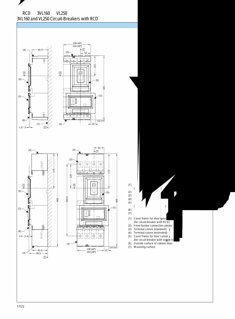
1/122
带 RCD的 3VL160和 VL250断路器3VL160 and VL250 Circuit-Breakers with RCD
(3)
X
(5)
(1)
1.0 - 3
NSK-8791
81.5 52
321
101
138 (4P)103 (3P)
(7)
(6)
(3)
(1)
(5)
(3)
Z
Y
X
22
(4)
(4)
(4)
(2)
(4)
(1)
(5)
1.0 - 3
95.5 81.5
465
173
359.
5
120
138 (4P)103 (3P)
22
173
465
52
(6)
(1)
(5)
NSK-8792
X
Z
Y
X
端子盖 Terminal covers
(1) 柜门开孔面框(用于带 RCD 的断路器)
(2) 正面母排连接件(3) 端子盖(标准)(4) 端子盖(加长)(5) 柜门开孔面框
(用于带扳动手柄的断路器)(6) 柜门外表面(7) 安装表面
(1) Cover frame for door cutout(for circuit-breaker with RCD)
(2) Front busbar connection pieces(3) Terminal covers (standard)(4) Terminal covers (extended)(5) Cover frame for door cutout
(for circuit-breaker with toggle handle)(6) Outside surface of cabinet door(7) Mounting surface
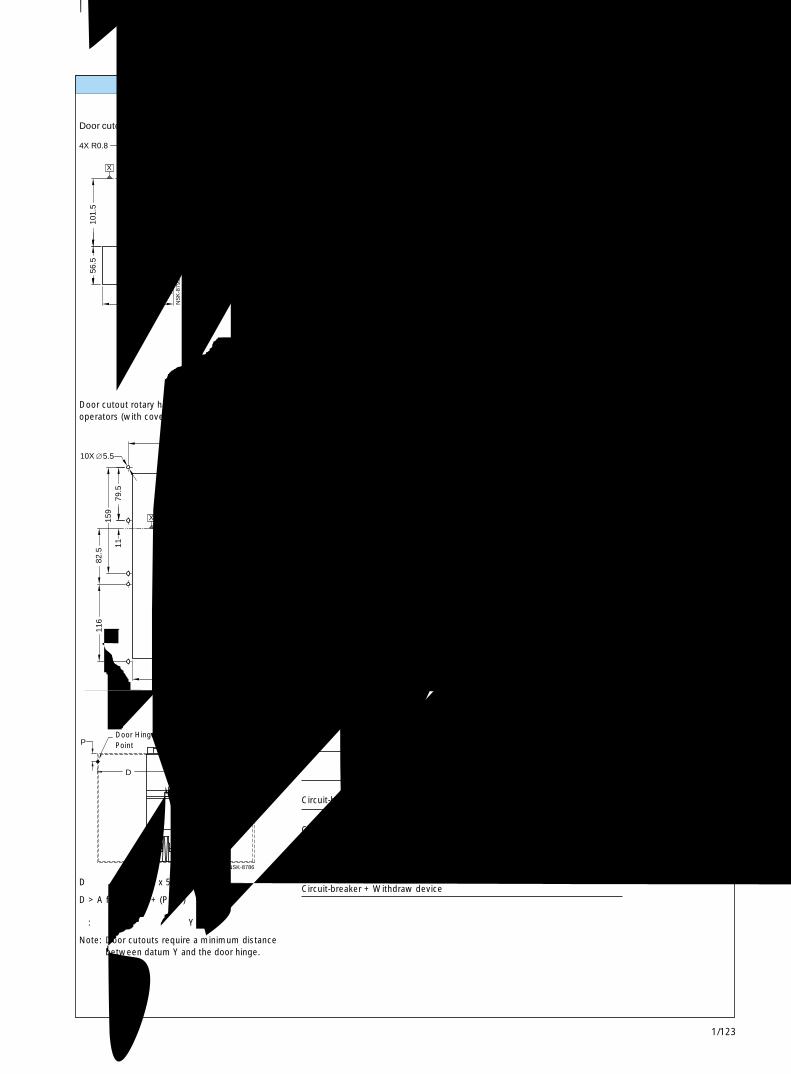
1/123
带 RCD的 3VL160和 VL250断路器3VL160 and VL250 Circuit-Breakers with RCD 1
4X R0.8
54 107.5
56.5
10
1.5
33
65
16.5
32.5
NS
K-8
793
Y
X
90
92
55
127
8X
68
64 128136
41.5
68
105
52
83
96
46 92.5
5.5Y
X
NS
K-8
794a
42
6532
.5
32.5 65
4.5
2.5
3
NSK-8795
4X
X
Y
159
116
82.5
1179
.5
5.5
196.
5
73.5
147.5
10
9.5
275
160.5
80
81
10XY
X
NSK-8796a
X
106.
5
66.5
106.5
53.5
97 48.5
59
90.5
Y
NS
K-1
019
6X26 (4P)
253
2X
70 (4P)35
17.5
270.
5
105 (4P)
35
13
70
75.5
X Y
26 (3P)8X
5.2 (3P)4X 5.2 (4P)
NS
K-8
797
P Y
D
NSK-8786
面板开孔 Panel cutouts
断路器的扳动手柄门开孔(带面框)
Door cutout toggle operator (with cover frame)
断路器的扳动手柄门开孔(不带面框)
Door cutout toggle operator (without cover frame)
加长旋转操作机构的门开孔
Door cutout extended handle rotary operator
背后连接柱螺栓的孔型和开孔
Hole pattern cutoutrear connection studs
旋转操作机构和储能操作机构的门开孔(带面框)
Door cutout rotary handle and stored energyoperators (with cover frame)
旋转操作机构的门开孔(不带面框)
Door cutout rotary handle operator(without cover frame)
注: 门开孔要求在基准轴Y和门铰链之间的最小间隔。
Note: Door cutouts require a minimum distancebetween datum Y and the door hinge.
门铰链点Door HingePoint
AVL160X to VL250
仅有断路器 100Circuit-breaker only
断路器 + 插入式插座 + 储能操作机构 100Circuit-breaker + Plug-in socket + Stored energy operator
断路器 + 插入式插座 + 旋转手柄 200Circuit-breaker + Plug-in socket + Rotary handle
断路器 + 抽出式装置 200Circuit-breaker + Withdraw device
D > 表中的 A + (P x 5)
D > A from table + (P x 5)
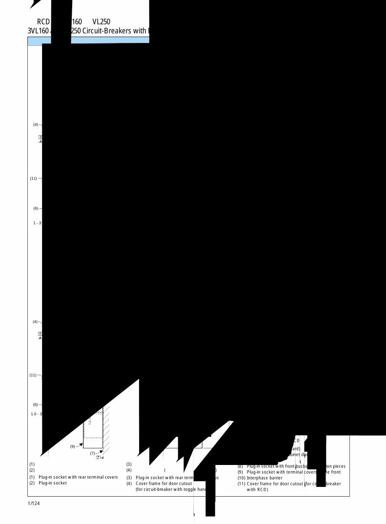
1/124
带 RCD的 3VL160和 VL250断路器3VL160 and VL250 Circuit-Breakers with RCD
(6)
(11)
(7)(1)
(5)
(4)
Z
(3)
(3)
(2)
(1)
113
1 - 3
1- 3
223.
5
52.5
61.5
78.5 174
58.5
315
1 -
3
345 45
.5
50
11.1
70 (4P)35 35
135 (4P)100 (3P)
12.5
98
130 (3P)-165 (4P)
38
190
65
35.5
38
35 (3P)70 (4P)
17.5 4X 5.2
X
Y
25.5
Z
Y
X Y
NSK-8800
5
(9)
(7)
(11)
(6)
(4)
(8)
(9)
(9)
(8)
(11)
(4)
(10)
1.0 - 3
28.5
38.5 165.5
174
5
5.2
379.
5
550.
5
25.5
12.5
11.1
216
3549.5
135 (4P)100 (3P)
130.
5
35
315
98
35 (3P)70 (4P)
17.5
Y
35
X
Z
X
4X
Y
X
NSK-8801
插入式插座和附件 Plug-in socket and accessories
带扁平母排背后端子的插入式插座的孔型和开孔
Hole pattern and cutout for plug-in socketwith rear terminals flat bus
(1) Plug-in socket with rear terminal covers(2) Plug-in socket
带正面母排连接件的插入式插座的孔型
Hole pattern for plug-in socketwith front busbar connection pieces
(1) 带背后端子盖的插入式插座(2) 插入式插座
(3) 带扁平母排背后端子的插入式插座(4) 柜门开孔面框 (用于带扳动手柄的断路器)
(5) 端子盖(标准)(6) 柜门外表面(7) 安装表面(8) 带正面母排连接件的插入式插座(9) 前部带端子盖的插入式插座(10) 相间隔板(11) 柜门开孔面框 (用于带 RCD 的断路器)
(3) Plug-in socket with rear terminals flat bus(4) Cover frame for door cutout
(for circuit-breaker with toggle handle)
(5) Terminal covers (standard)(6) Outside surface of cabinet door(7) Mounting surface(8) Plug-in socket with front busbar connection pieces(9) Plug-in socket with terminal covers in the front(10) Interphase barrier(11) Cover frame for door cutout (for circuit-breaker
with RCD)
4 极断路器CIRCUIT-BREAKER4 POLE
典型 TYPICAL典
型 T
YP
ICA
L
典型
TYP
ICA
L

1/125
带 RCD的 3VL160和 VL250断路器3VL160 and VL250 Circuit-Breakers with RCD 1
(1)
(6)
(10)
(8)
(12)
(11)
(7)
X
(4)
(5)
1 - 3
226.5
337
14
31.5 140
305.5
Z
NSK-8802
(12)
(6)
(3)
(10)
(9)
(11)
(7)
(2)
(5)
1 - 3
14
207.5 129
218.5 279.5
NSK-8803
Z
X
(7)
(12)
(3)
(10)
(6)
(11)
(9)
(2)
(5)
27.5
14
101.5
307
207.5 246
1 - 3NSK-8804
X
Z
(6)
(1)
(8)
(10)
(11)
(12)
(5)
(4)
(7)1 - 3
14
58.5
305.5 226.5
112.5
364
27.5 Z
NSK-8913
X
抽屉型和附件 Drawout version and accessories
3VL160和VL250断路器,带 RCD和储能操作机构 (运行位置)
3VL160 and VL250 circuit-breakers with RCDand stored energy operator (engaged position)
3VL160和VL250断路器,带 RCD和储能操作机构 (断开位置)
3VL160 and VL250 circuit-breakers with RCDand stored energy operator (disengaged position)
(1) Cylinder locks(2) Rotary handle operator(3) Padlock hook(4) Stored energy operator(5) Cover frame for door cutout (for circuit-breaker with operator)(6) Outside surface of cabinet door(7) Mounting surface(8) Cover frame for door cutout (for circuit-breaker with RCD, motor operator type)(9) Cover frame for door cutout (for circuit-breaker with RCD, handle operator type)(10) RCD extended escutcheon(11) Withdraw device(12) Withdraw crank location
3VL160和VL250断路器,带 RCD和旋转操作机构 (运行位置)
3VL160 and VL250 circuit-breakers with RCDand rotary handle operator (engaged position)
3VL160和VL250断路器,带 RCD和旋转手柄操作机构 (断开位置)
3VL160 and VL250 circuit-breakers with RCDand rotary handle operator (disengaged position)
(1) 柱形锁(2) 旋转操作机构(3) 挂锁钩(4) 储能操作机构(5) 柜门开孔面框 (用于带操作机构的断路器)(6) 柜门外表面(7) 安装表面(8) 柜门开孔面框 (用于带 RCD 的断路器,电动机操作机构类型)(9) 柜门开孔面框 (用于带 RCD 的断路器,手柄操作机构类型)(10) RCD 加长框(11) 抽出式装置(12) 抽出式曲柄位置

1/126
带 RCD的 3VL160和 VL250断路器3VL160 and VL250 Circuit-Breakers with RCD
(11)
(6)
(10)
(3)
(9)
(12)
(7)
(5)
Z
1.0 - 3
14
129
218.5 207.5
X
NSK-8805
(11)
(10)
(9) (9)
(12)
(3)
(5)
74.5
171.
5
120.
5 (1
2)
187 (4P) - 152.5 (3P)
78 (12)85
206
86.5 173
34 Y
NS
K-8
806
X
(8)
(10)
(11)
(9)
(12)
(4)
(5)
78 (12)
187 (4P) - 152.5 (3P)
206
171.
5
74.5
120.
5 (1
2)
85
34 86.5
173
NS
K-8
807
Y
X
(9)
(10)
(11)
(9)
(12)
(2)
(5)
187 (4P) - 152.5 (3P)
78 (12)85
206
171.
5
74.5
173 86.5
34
120.
5 (1
2)
Y
NS
K-8
808
X
(10)
(6)
(3)
(9)
(11) (7)
(5)
1.0 - 3
14
207.5 129
246
27.5
NSK-8914
X
Z
(2) 旋转操作机构(3) 断路器加长框(4) 储能操作机构(5) 柜门开孔面框
(用于带操作机构的断路器)(6) 柜门外表面(7) 安装表面(8) 柜门开孔面框
(用于带 RCD 的断路器,电动机操作机构)(9) 柜门开孔面框
(用于带 RCD 的断路器,旋转操作机构)(10) RCD 加长框(11) 抽出式装置(12) 抽出式曲柄位置
3VL160和 VL250断路器,带 RCD和加长框(运行位置)
3VL160 and VL250 circuit-breakers with RCDand extended escutcheon (engaged position)
抽出式装置WITHDRAW DEVICE
3VL160和 VL250断路器,带RCD和加长框(断开位置)
3VL160 and VL250 circuit-breakers with RCDand extended escutcheon (disengaged position)
抽出式装置WITHDRAW DEVICE
抽出式装置WITHDRAW DEVICE
(2) Rotary handle operator(3) Circuit-breaker extended escutcheon(4) Stored energy operator(5) Cover frame for door cutout
(for circuit-breaker with operator)(6) Outside surface of cabinet door(7) Mounting surface(8) Cover frame for door cutout
(for circuit-breaker with RCD, motor operator type)(9) Cover frame for door cutout
(for circuit-breaker with RCD, handle operator type)(10) RCD extended escutcheon(11) Withdraw device(12) Withdraw crank location
抽屉型和附件 Drawout version and accessories
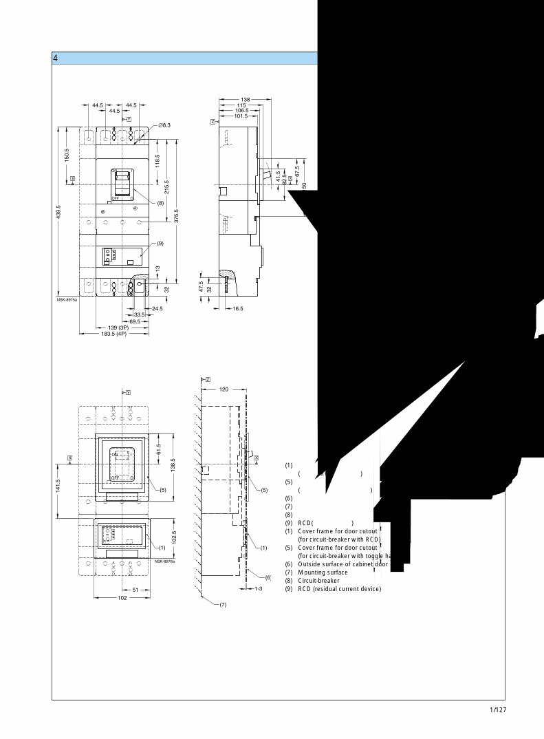
1/127
带 RCD的 3VL400断路器3VL400 Circuit-Breakers with RCD 1
4极断路器 Circuit-breakers, 4-pole
带RCD正面连接母排的 3VL400断路器的安装孔型
Mounting hole pattern 3VL400 circuit-breakerwith RCD front connection bus
(1) 柜门开孔面框(用于带 RCD 的断路器)
(5) 柜门开孔面框(用于带扳动手柄的断路器)
(6) 柜门外表面(7) 安装表面(8) 断路器(9) RCD(剩余电流装置)(1) Cover frame for door cutout
(for circuit-breaker with RCD)(5) Cover frame for door cutout
(for circuit-breaker with toggle handle)(6) Outside surface of cabinet door(7) Mounting surface(8) Circuit-breaker(9) RCD (residual current device)
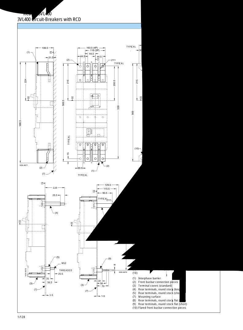
1/128
带 RCD的 3VL400断路器3VL400 Circuit-Breakers with RCD
56.5
31
(7)
(3)
25.5
1-5
M12
(5)
X
Z
(4)
25.5
116
NS
K-8
978
连接件和相间隔板 Connections and interphase barriers
(1) 相间隔板(2) 正面母排连接件(3) 端子盖(标准)(4) 背后端子,圆杆(长)(5) 背后端子,圆杆(短)(7) 安装表面(8) 背后端子,扁平圆杆(长)(9) 背后端子,扁平圆杆(短)(10) 扩口正面母排连接件
(1) Interphase barrier(2) Front busbar connection pieces(3) Terminal covers (standard)(4) Rear terminals, round stock (long)(5) Rear terminals, round stock (short)(7) Mounting surface(8) Rear terminals, round stock flat (long)(9) Rear terminals, round stock flat (short)(10) Flared front busbar connection pieces
典型TYPICAL
典型TYPICAL
典型TYPICAL
典型 TYPICAL 典型 TYPICAL
典型
TY
PIC
AL
典型
TY
PIC
AL
典型TYPICAL
典型TYPICAL
螺纹THREADED
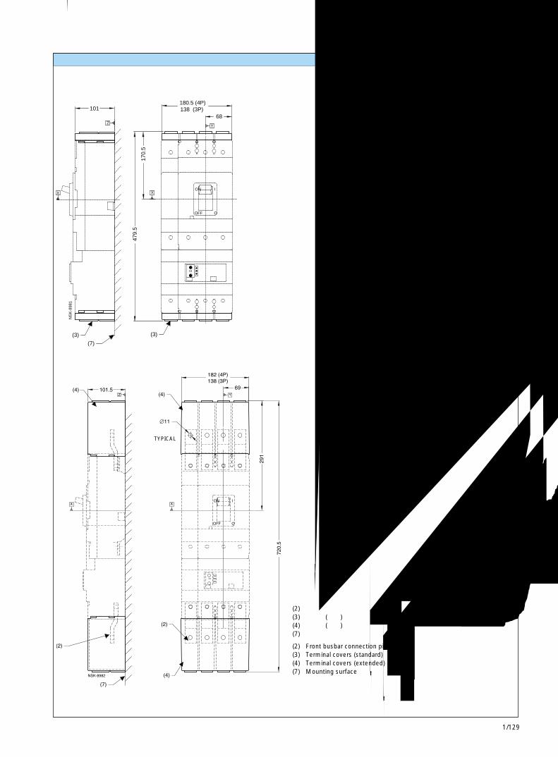
1/129
带 RCD的 3VL400断路器3VL400 Circuit-Breakers with RCD 1
(7)
(3)
X
Z
101
NS
K-8
981
(3)
180.5 (4P)138 (3P)
479.
5
X
170.
5
Y
68
ON
OFF
I
O
端子盖 Terminal covers
(2) 正面母排连接件(3) 端子盖(标准)(4) 端子盖(加长)(7) 安装表面
(2) Front busbar connection pieces(3) Terminal covers (standard)(4) Terminal covers (extended)(7) Mounting surface
典型TYPICAL
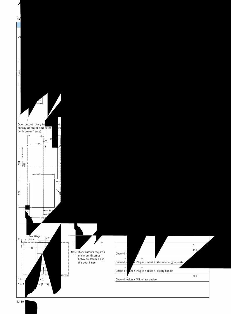
1/130
带 RCD的 3VL400断路器3VL400 Circuit-Breakers with RCD
157.
5
54
107.5
Y
56.5
62
31
X
42.5
84.5
NS
K-8
983
100
150.
5
66.5
53.5
106.5
162
66132
X
Y
NS
K-8
984
P Y
D
NSK-8786
面板开孔 Panel cutouts
注: 门开孔要求在基准轴Y 和门铰链之间的最小间隔。
Note: Door cutouts require aminimum distancebetween datum Y andthe door hinge.
门铰链点Door HingePoint
A
仅有断路器 150Circuit-breaker only
断路器 + 插入式插座 + 储能操作机构 150Circuit-breaker + Plug-in socket + Stored energy operator
断路器 + 插入式插座 + 旋转手柄 200Circuit-breaker + Plug-in socket + Rotary handle
断路器 + 抽出式装置 200Circuit-breaker + Withdraw deviceD > 表中的 A + (P x 5)
D > A from table + (P x 5)
旋转操作机构的门开孔 (不带面框)
Door cutout rotary handle operator(without cover frame)
断路器的扳动手柄门开孔 (带面框)
Door cutout toggle operator (with cover frame)
加长旋转操作机构的门开孔
Door cutout extended handle rotary operator
旋转操作机构、储能操作机构和加长框的门开孔(带面框)
Door cutout rotary handle operator, storedenergy operator and extended escutcheon(with cover frame)
背后连接柱螺栓的孔型和开孔
Hole pattern and cutouts rear connecting studs
断路器的扳动手柄门开孔 (带面框)
Door cutout toggle operator (with cover frame)
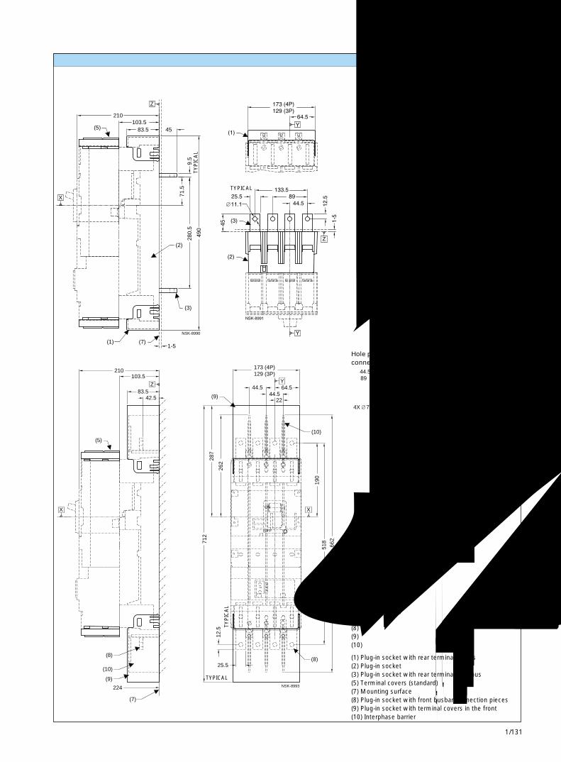
1/131
带 RCD的 3VL400断路器3VL400 Circuit-Breakers with RCD 1
(3)
280.
5
(7)(1)1-5
(2)
9.5
71.5
103.5 (5)
210
45 83.5
490
Z
X
NSK-8990
(7)
224
(10)
(9)
(8)
(5)
103.5
83.5
210
42.5
12.5
25.5 (8)
712
518
662
44.5 22
262
287
(9)
173 (4P)129 (3P)
64.5 44.5
(10)
190
155
449
44.5 (3P)89 (4P)
22
ON I
OFF O
Y
XX
Z
Y4X 7.1
X
NSK-8993
插入式插座和附件 Plug-in socket and accessories
带扁平母排背后端子的插入式插座的孔型和开孔
Hole pattern and cutouts plug-in socketrear terminals flat bus
(1) 带背后端子盖的插入式插座(2) 插入式插座(3) 带扁平母排背后端子的插入式插座(5) 端子盖(标准)(7) 安装表面(8) 带正面母排连接件的插入式插座(9) 带正面连接端子盖的插入式插座(10) 相间隔板
(1) Plug-in socket with rear terminal covers(2) Plug-in socket(3) Plug-in socket with rear terminals flat bus(5) Terminal covers (standard)(7) Mounting surface(8) Plug-in socket with front busbar connection pieces(9) Plug-in socket with terminal covers in the front(10) Interphase barrier
带正面母排连接件的插入式插座的孔型
Hole pattern plug-in socket front busbarconnection pieces
典型TYPICAL
典型
TY
PIC
AL
典型TYPICAL
典型
TY
PIC
AL
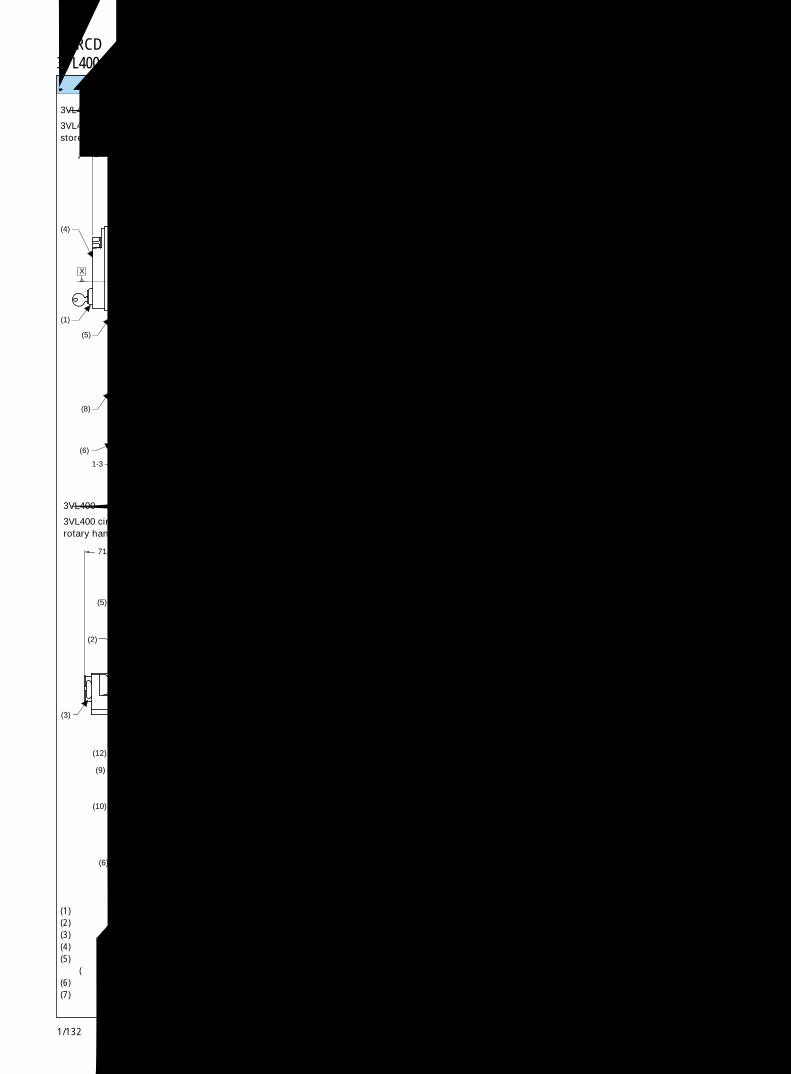
1/132
带 RCD的 3VL400断路器3VL400 Circuit-Breakers with RCD
(7)
(11)
(8)
(6)
1-3
(10)
(1)
(5) (12)
224
(4)
122.5
364 327.5
Z
X
NSK-8994
(7)
1-3
(8)
(6)
(10)
(1)
(5) (12)
(11)
(4)
95.5 27
391.5 327.5
197 224
Z
X
NSK-8995
1-3
(6)
(11)
(7)
(9)
(10)
(12)
(3)
(5)
(2)
148
71.5
251.5
266
X
NSK-8996
Z
(6)
1-3 (11)(7)
(10)
(3)
(9)
(12)
(5)
(2)
27 121
71.5
148 251.5
293
Z
X
NSK-8997
3VL400断路器,带 RCD和储能操作机构的抽出型断路器(运行位置)
3VL400 circuit-breaker with RCD drawout versionstored energy operator (engaged position)
(1) Cylinder locks(2) Rotary handle operator(3) Padlock hook(4) Stored energy operator(5) Cover frame for door cutout
(for circuit-breaker with operator)(6) Outside surface of cabinet door(7) Mounting surface
3VL400断路器,带RCD,旋转操作机构的抽出型(运行位置)
3VL400 circuit-breaker with RCD drawout versionrotary handle operator (engaged position)
3VL400断路器,带 RCD和旋转操作机构的抽出型(断开位置)
3VL400 circuit-breaker with RCD drawout versionrotary handle operator (disengaged position)
3VL400断路器,带 RCD,储能操作机构的抽出型断路器(断开位置)
3VL400 circuit-breaker with RCD drawout versionstored energy operator (disengaged position)
(1) 柱形锁(2) 旋转操作机构(3) 挂锁钩(4) 储能操作机构(5) 柜门开孔面框
(用于带操作机构的断路器)(6) 柜门外表面(7) 安装表面
(8) 柜门开孔面框(用于带RCD的断路器,电动机操作机构类型)
(9) 柜门开孔面框(用于带RCD的断路器,操作机构类型)
(10) RCD 加长框(11) 抽出式装置(12) 抽出式曲柄位置
(8) Cover frame for door cutout(for circuit-breaker with RCD,motor operator type)
(9) Cover frame for door cutout(for circuit-breaker with RCD,handle operator type)
(10) RCD extended escutcheon(11) Withdraw device(12) Withdraw crank location
抽屉型和附件 Drawout version and accessories
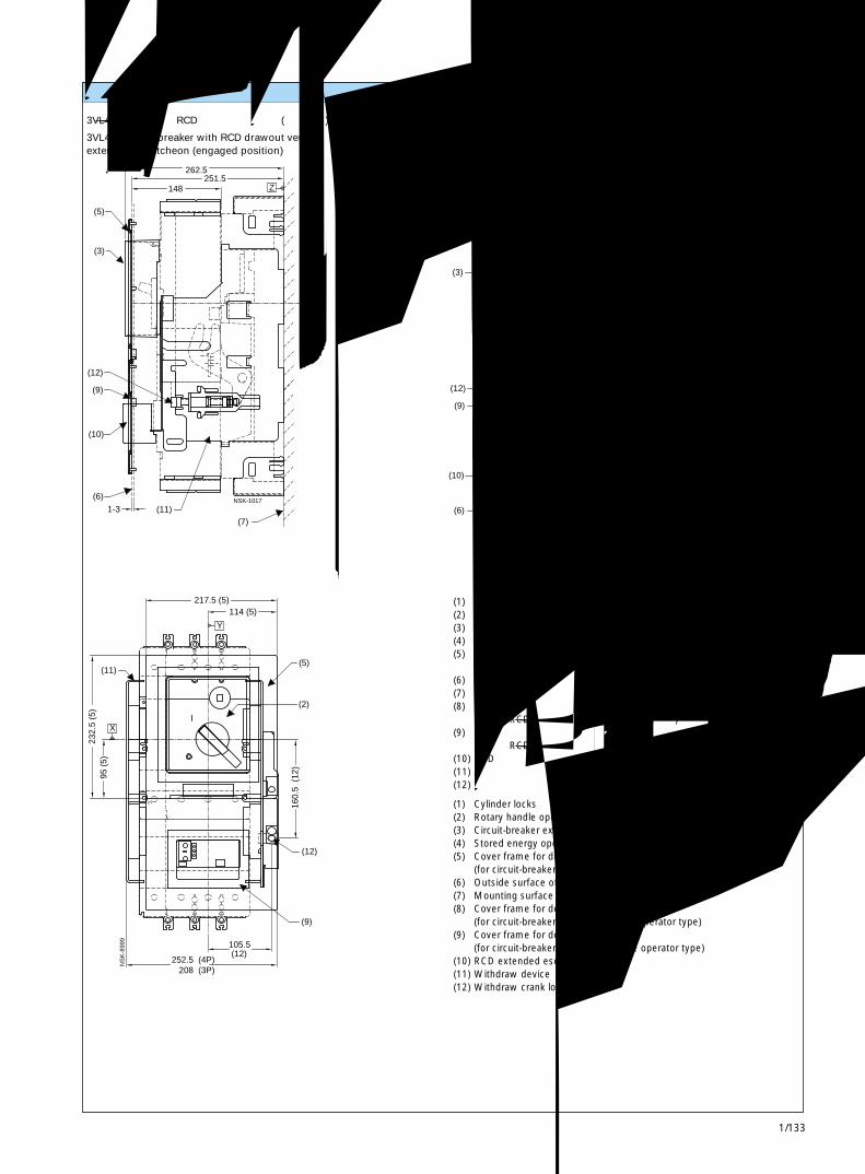
1/133
带 RCD的 3VL400断路器3VL400 Circuit-Breakers with RCD 1
1-3 (11)(7)
(5)
(12)
(6)
(10)
(9)
(3)
148 251.5
262.5
Z
X
NSK-1017
289.5
121
1-3
(10)
(6)
(9)
(12)
(5)
(3)
(7)(11)
27148
251.5
X
Z
NSK-8998
208 (3P)252.5 (4P)
105.5 (12)
(9)
232.
5 (5
)95
(5)
160.
5 (
12)
(12)
(2)
(11)
217.5 (5)114 (5)
(5)
Y
X
NS
K-8
999
3VL400断路器,带 RCD和加长框的抽出型(运行位置)
3VL400 circuit-breaker with RCD drawout versionextended escutcheon (engaged position)
3VL400断路器,带 RCD和加长框的抽出型(断开位置)
3VL400 circuit-breaker with RCD drawout versionextended escutcheon (disengaged position)
(1) 柱形锁(2) 旋转操作机构(3) 断路器加长框(4) 储能操作机构(5) 柜门开孔面框
(用于带操作机构的断路器)(6) 柜门外表面(7) 安装表面(8) 柜门开孔面框
(用于带 RCD 的断路器,电动机操作机构类型)(9) 柜门开孔面框
(用于带 RCD 的断路器,手柄操作机构类型)(10) RCD 加长框(11) 抽出式装置(12) 抽出式曲柄位置
(1) Cylinder locks(2) Rotary handle operator(3) Circuit-breaker extended escutcheon(4) Stored energy operator(5) Cover frame for door cutout
(for circuit-breaker with operator)(6) Outside surface of cabinet door(7) Mounting surface(8) Cover frame for door cutout
(for circuit-breaker with RCD, motor operator type)(9) Cover frame for door cutout
(for circuit-breaker with RCD, handle operator type)(10) RCD extended escutcheon(11) Withdraw device(12) Withdraw crank location
抽屉型和附件 Drawout version and accessories
IEC SENTRON塑壳式断路器Molded Case Circuit-Breakers IEC SENTRON
页号Page
页号Page
3WN6交流断路器 3WN6 Circuit-Breakers for AC
概览 2/2
分解图 2/3
说明 2/4合闸准备就绪 2/6辅助开关和信号发送开关 2/6固定式和抽屉式断路器 2/7导向框架 2/8过电流脱扣器系统 2/10手持式编程器 2/15过电流脱扣器功能一览表 2/16通讯模块 2/18测量模块 2/18电流互感器的连接 2/19分闸、合闸和锁定装置 2/20相互机械联锁 2/22电源转换装置 2/23
选型和订货数据断路器3 极,固定式和抽屉式,至 3200A 2/244 极,固定式和抽屉式,至 3200A 2/28负荷隔离开关3 极,固定式和抽屉式,至 3200A 2/324 极,固定式和抽屉式,至 3200A 2/36
用于 3WN6的其他规格,附件用于 3WN6 的其他规格用于固定式和抽屉式断路器的其他规格 2/40用于抽屉式断路器和导向框架的其他规格 2/44
用于 3WN6 的附件和辅助装置用于固定式和抽屉式断路器的附件和辅助装置 2/46
用于抽屉式断路器的附件-导向框架 2/50
用于改装的附件用于 3WN6 固定式和抽屉式断路器可改装的附件 2/52
用于固定式和抽屉式断路器的备件 2/60
技术数据 2/63
脱扣特性曲线 2/70
断路器电气原理图 2/71
外形尺寸和安装尺寸 2/74
Overview 2/2
Explode drawing 2/3
Description 2/4Readiness to close 2/6Auxiliary switches and signalling switches 2/6Fixed-mounted and draw-out circuit-breakers 2/7Guide frame 2/8Overcurrent release system 2/10Hand-held control unit 2/15Function overview of overcurrent release system 2/16Communication module 2/18Measuring module 2/18Connection of the current transformer 2/19Opening, closing and interlocking device 2/20Mutual mechanical interlocking 2/22Network-switching control unit 2/23
Selection and ordering dataCircuit-Breakers3-pole, fixed-mounted and draw-out version , up to 3200A 2/244-pole, fixed-mounted and draw-out version, up to 3200A 2/28Non-Automatic Circuit-Breakers3-pole, fixed-mounted and draw-out version, up to 3200A 2/324-pole, fixed-mounted and draw-out version, up to 3200A 2/36
Further versions and accessories for 3WN6Further versions for 3WN6Further versions for fixed-mounted and draw-out version 3WN6 2/40Further versions for draw-out version and guide frame 2/44
Accessories and supplementary devices for 3WN6Accessories and supplementary devices for 2/46fixed-mounted and draw-out version 3WN6Accessories for draw-out version - guide frame 2/50
Accessories for retrofittingAccessories for retrofitting for fixed-mounted 2/52and draw-out version 3WN6Spare parts for fixed-mounted and draw-out version 3WN6 2/60
Technical data 2/63
Tripping characteristies 2/70
Example of full circuit diagram 2/71
Dimensions 2/74
断路器最大至 3200ACircuit-Breakers up to 3200A
2/0

IEC SENTRON塑壳式断路器Molded Case Circuit-Breakers IEC SENTRON
2
具有通讯能力的断路器 Communication-Capable Circuit-Breakers
页号Page
页号Page
断路器最大至 3200ACircuit-Breakers up to 3200A
2/1
描述Description具有通讯能力的 3VL, 3WN6, 3WN1, 3WS1 断路器 2/85Communication-Capable 3VL, 3WN6, 3WN1, 3WS1 Circuit-Breakers具有通讯能力的 3WN6 断路器 2/87Communication-Capable 3WN6 Circuit-Breakers
选型和订货数据Selection and ordering data具有通讯能力的 3VL 断路器 - 快速选型 2/89至800A,固定式, 3极Communication-Capable 3VL Circuit-Breakers, up to 800A ,for Fixed Mounting, 3-pole具有通讯能力的 3WN6 断路器 - 快速选型, 2/90至 3200A,用于固定式和抽屉式安装,3 极Communication-Capable 3WN6 Circuit-Breakers, up to 3200A , 3-pole具有通讯能力的 3WN1 断路器 - 快速选型, 2/91至 6300A,用于固定式和抽屉式安装,3 极Communication-Capable 3WN1 Circuit-Breakers, up to 6300A , 3-pole
附件Accessories用于可通讯 3VL 的附件 2/92Accessories for Communication-Capable 3VL用于可通讯 3WN6 的附件 2/93Accessories for Communication-Capable 3WN6用于可通讯 3WN1 和 / 或 3WS1 的附件 2/95Accessories for Communication-Capable 3WN1 and/or 3WS1

2/2
3W.系列断路器概览
3W. Circuit-breakerOverview
3WN6-经济型万能式断路器,最大至 3200A 3WN6 - The economical all-rounder, up to 3200A
详见 3WN6 一章See Chapter 3WN6 for details
● 在建筑和工业应用领域中理想的配电保护产品。节省空间,维护方便,模块化的结构使得断路器适用于各种系统,对于各种系统不同的要求方便的进行改型。
● 额定电流:630 至 3200A● 额定电压:至 690V AC● 500V 时的短路分断能力:至 80kA● 690V 时的短路分断能力:至 50kA● 完全选择性分断至 65kA
● Ideal for the distribution of energy in both buildings and industrialapplications Space saving and maintenance friendly.The modularconstruction allows the breaker to be easily adapted to suit theindividual requirements of each system.
● Rated current: 630 to 3200A● Rated voltage: to 690V AC● Switching capacity at 500V: up to 80kA● Switching capacity at 690V: 50kA● Full discrimination up to 65kA
3WN1 直流断路器 3WN1 DC circuit-breakers
● 适用于直流配电系统保护,可作为直流电动机、发电机及变频器或电力拖动设备的保护。
● 额定电流:DC800 至 5000A● 额定电压:至DC1000V● 在直流 300V时的短路分断能力:至 40kA● 在直流 1000V 时的短路分断能力:至 15kA
● 3WN1 DC circuit-breakers suitable for service in DC installations, forsuch tasks as motor protection, generator protection, converterprotection or traction equipment protection.
● Rated current: 800 to 5000A DC● Rated voltage: up to 1000V DC● Short-circuit breaking capacity at 300V DC: up to 40kA● Short-circuit breaking capacity at 1000V DC: up to 15kA
3WV直流快速断路器,至 8000A 3WV High speed DC circuit-breakers up to 8000A
● 3WV 直流快速断路器用于直流系统中的特殊场合,如炼钢行业中的晶闸管保护和拖动系统保护。
● 额定电流:至 DC8000A● 额定电压:至DC1500V● 短路分断能力为无限,短路电流分断速率至:20kA/ms 或 10kA/ms● 分闸时间仅为约 3ms● 单极,固定安装式或抽屉式结构
● 3WV High speed DC circuit-breakers are suitable for special service inDC installations for such tasks as thyristor protection in steel industryand traction equipment protection.
● Rated current: up to 8000A DC● Rated voltage: up to 1500V DC● Short-circuit breaking capacity unlimited up to rates of current-rise of
20kA/ms or 10kA/ms respectively● Opening delay only approx. 3 ms● Single-pole, fixed-mounting or drawout versions are available
�
有关 3WN1,3WS1,UL 和 3WV 断路器的细节,请与就近的西门子办事处联系。Please contact your local Siemens office for details of 3WN1, 3WS1, UL and 3WV circuit-breakers.

2/3
2
3W.系列断路器概览
3W. Circuit-breakerOverview分解图 Explode drawing
1 断路器本体2 控制面板3 曲柄4 门密封框,防护等级 IP545 主回路水平后置6 主回路连接前置,单孔,顶部和底部7 主回路连接前置,双孔,顶部和底部8 主回路垂直后置
9 储能用电动机10 主触头11 导向框架12 安全挡板13 电流互感器14 位置信号发送开关15 灭弧室16 电气合闸线圈
17 分励线圈18 欠电压线圈19 辅助触头20 辅助接线端子块21 操作计数器22 带微处理器的电子式过电流脱扣器
1 Basic circuit-breaker2 Control panel3 Crank handle4 Door sealing frame, IP 545 Main connections at the rear, horizontal6 Main connections accessible from the
front, top and bottom, single-hole barends
7 Main connections accessible from thefront, top and bottom, double-holebar ends
8 Main connections at therear, vertical
9 Motor for energy storage10 Main contact sets11 Guide frame12 Shutter13 Current transformer14 Position signaling switches15 Arc chute16 Closing solenoid17 Shunt release
18 Undervoltage release19 Auxiliary contacts20 Auxiliary connector21 Operating cycle counter22 Solid-state, microprocessor-
controlled overcurrent release
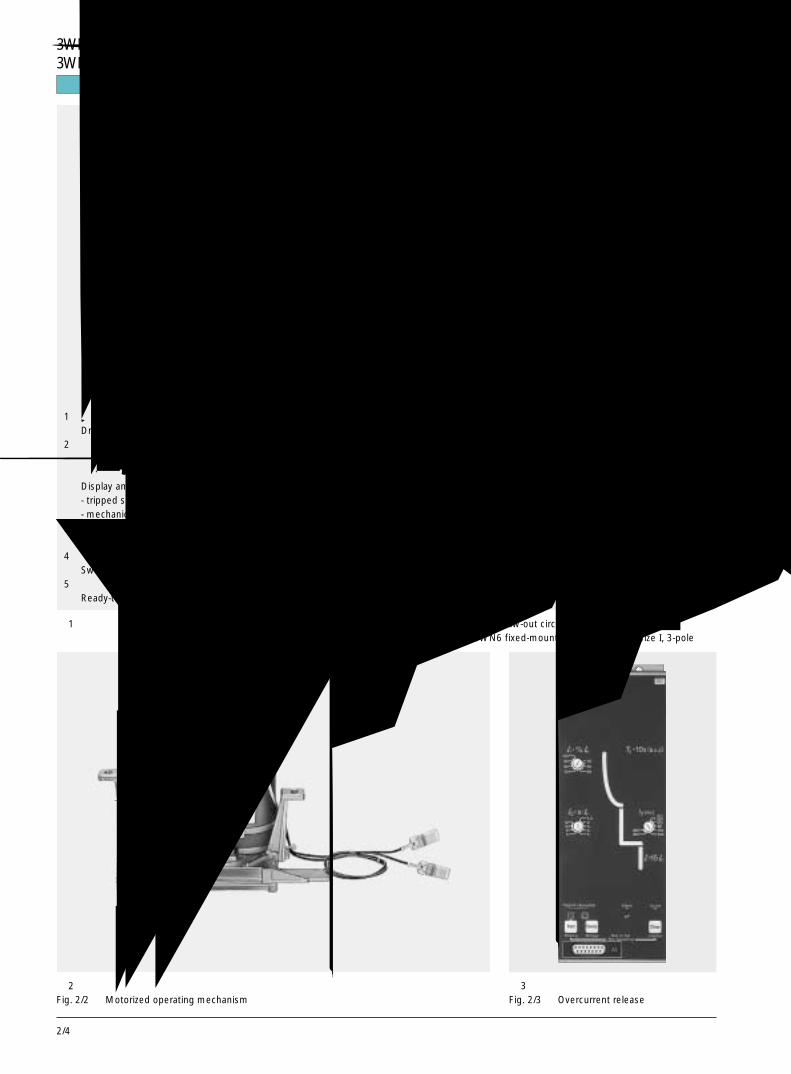
2/4
3WN6断路器,至 3200A3WN6 Circuit-Breakers, up to 3200A说明 Description
1 抽屉式断路器Draw-out circuit-breaker
2 显示和复位按钮,用于-脱扣信号发送触头-机械重合闸锁定Display and reset button for- tripped signalling contact- mechanical reclosing lockout
3 储能状态显示器Stored-energy indicator
4 通断状态显示器Switching-state indicator
5 合闸准备就绪状态显示器Ready-to-close indicator
6 机械合闸按钮,带密封盖ON button,mechanical with sealing cap
7 机械分闸按钮OFF button,mechanical
8 电气合闸按钮ON button,electrical
9 过电流脱扣器Overcurrent release
10 位置显示器Position indicator
11 导向框架Guide frame
12 导轨Guide rails
13 辅助接线端子Auxiliary current connectors
14 曲柄操作孔Crank hole
15 操作手柄Crank handle
16 位置信号发送开关Position signalling switch
17 透明面罩Transparent cover
图 2 电动机操作机构Fig. 2/2 Motorized operating mechanism
图 3 过电流脱扣器Fig. 2/3 Overcurrent release
图 1 左:3WN6 抽屉式断路器,尺寸等级 I,3 极右:3WN6 固定式断路器,尺寸等级 I,3 极
Fig. 2/1 Left: 3WN6 draw-out circuit-breaker, size I, 3-poleRight: 3WN6 fixed-mounted circuit breaker, size I, 3-pole

2/5
2
说明 Description
符合标准IEC947-2,DIN VDE0660第101部分,耐气
候等级符合 DIN IEC68 第 30-2 部分。3WN6 还获得 ZS、ABS、GL、LRS、BV、
DNV、RINA 和 PRS 等多国船级社认证。工作条件
3WN6断路器耐气候条件符合DIN IEC68第30-2部分。他们一般应用于非恶劣工作条件的密闭区域中。设计分断能力:65/80kA额定电流:630~3200A额定工作电压:AC690V
3WN6断路器配有过电流脱扣器,操作机构和辅助触头,如果需要,还可安装欠电压脱扣器和分励脱扣器。
负荷隔离开关不带过电流脱扣器。安装方式
有固定式或抽屉式两种安装方式。操作机构(见图 2):
可提供下述三种操作机构:-手动储能,机械合闸式操作机构。-手动储能,机械和电气合闸式操作机构。-手动 / 电动机储能,机械和电气合闸式操作机构。过电流脱扣器(见图 3)
微处理器控制的电子式过电流脱扣器系统不需要另外的电源供电,可满足对配电系统、电动机、变压器和发电机等负载的各种保护要求。
对过电流脱扣器的介绍见第 2/10页。安全性和可靠性-门密封框使防护等级提高,断路器能完全地就地操作;
-可从断路器的顶部或底部进线;-抽屉式断路器可用标准锁锁定,以防断路器被移动;
-当断路器本体被取出后,可用标准锁锁住导向框架;
-过载和短路脱扣后的信号发送开关,带有机械重合闸锁定。使用简便-清楚的断路器位置指示器,通过辅助触头可发送信号
-合闸准备就绪显示器,及其信号发送开关作为断路器的基本配置之一。模块化
许多部件,如辅助脱扣器,电动机操作机构,过电流脱扣器和电流互感器等,可以很方便的就地更换,因而断路器可方便的根据系统变化的要求而改型。基本配置-用于过载和短路保护的电子式过电流脱扣器,短路保护具有时间分段短延时功能,带有发光二极管显示脱扣原因,还有用作运行显示,带有查询和试验按键。
-机械重合闸锁定
-脱扣信号发送开关-合闸准备就绪显示器及其信号发送开关-断路器上装有所需数量的接线端子-主回路连接水平后置通讯能力(见图 4)
采用国际标准化的 PROFIBUS 来传输如下数据:电流值、运行状态、脱扣原因等至中央计算机。可方便地实现能源管理,大大减少了电能支出。极低的功耗
电气元器件的低功耗减少了变压器的成本,还适合于安装在通风较差的狭小空间内。占用空间少
高性能的 3WN6 断路器只需占用很少的空间。尺寸等级 I 可装于 400mm 宽的柜子内。
StandardsIEC 947-2, DIN VDE 0660 Part 101.climate-proof to DIN IEC 68 Part 30-2Marine classification approvals: GL, LRS, BV,DNV, RINA and PRSOperating conditionsThe 3WN6 circuit-breakers are climate-proofaccording to DIN IEC 68 Part 30-2.They are intended for use in enclosed areaswhere excessive operating conditions do notoccur.DesignBreaking capacity: 65/80 kARated current: 630 to 3200 ARated operational voltage: AC 690 VThe 3WN6 circuit-breakers are supplied fullyequipped with overcurrent releases, operatingmechanism and auxiliary contacts and ifrequired, with undervoltage and shuntreleases.The non-automatic circuit-breakers are alwayssupplied without overcurrent release.MountingFixed-mounted or draw-out version.Operating mechanisms (see Fig. 2/2)The circuit-breakers can be supplied withdifferent operating mechanisms:- Manual operating mechanism with stored-
energy feature and mechanical closing.- Manual operating mechanism with stored-
energy feature and mechanical and electricalclosing.
- Motorized operting mechanism (also withmanual operation),with electrical andmechanical closing.
Overcurrent releases (see Fig. 2/3)The solid-state, microprocessor-controlledovercurrent release system does not dependon a separate power supply and permits thevarious protection requirements of distribution
systems, motors, transformers and generatorsto be taken into account.Safety and reliability- High degree of protection with door sealing
frame for full local operation of the circuit-breaker
- Feed-in to either top or bottom- Standard locking of draw-out circuit-breaker
to prevent it from being moved- Standard locking of guide frame when the
circuit-breaker is removed- Signalling switch for overload and short circuit
trip with mechanical reclosing lockoutEase of use- Clear position indicator with auxiliary switch
for signalling- Ready-to -close indicator with signalling
switch as safety standardModularityMany components, such as auxiliary releases,motorized operating mechanism, overcurrentreleases and current transformers, can beeasily exchanged later on, so that the circuit-breaker can meet future new requirements.Basic scope of supply- Solid state overcurrent releases for overload
and short circuit protection, short circuitrelease also with delay for time grading withLEDs for tripping cause, LED operatingdisplay, query and test buttons
- Mechanical reclosing lockout- Tripped signalling switch- Ready-to-close indicator with signalling
switch- Auxiliary connectors: the circuit-breake is
equipped with the required number ofconnectors
- Main conductors connection horizontal at therear
Communication capability (see Fig. 2/4)The internationally standardized PROFIBUS isused to transfer such data as current values,operating states, tripping causes, etc, tocentral computers.This makes energy management possible andhelps reduce energy costs significantly.Reduced energy consumption due tominimum dissipationThe low power requirement of the electricalcomponents reduces the cost of controltransformers. Suitable for limited spaces or forareas with reduced ventilation.Limited space requirementHigh performance with limited spacerequirement.Size I even fits into 400 mm wide cabinets.
西门子 3WN6 系列万能式断路器和 3VL 系列塑壳式断路器已获得中国船级社颁发的船用产品型式认可证书。详情请与您就近的西门子办事处联系。
Siemens 3WN6 Air Circuit Breakers and 3VL Moulded Case Circuit Breakers have got certificates of type approval for marine product issued
by China Classification Society. Please contact your local Siemens office for details of marine classification approvals.
3WN6断路器,至 3200A3WN6 Circuit-Breakers, up to 3200A

2/6
合闸准备就绪 Readiness to close
当断路器满足下列条件后,合闸准备就绪状态才会出现:-断路器处于分闸状态-储能机构已储能-欠电压脱扣器已正常得电-分励脱扣器没有得电-合闸线圈没有得电-分闸按钮不能锁定在分闸位置-机械重合闸锁定必须已释放-相互机械联锁处于无效状态-各种联锁应处于无效状态-抽屉式断路器上的曲柄孔应合上(断路器处于运行、试验或退出位置)
-过电流脱扣器已装好合闸准备就绪显示器和信号发送开关S7将
显示这些条件都已满足。只有这样才允许合闸。对于过电流脱扣器带有通讯模块的断路器,
不具备信号发送开关 S7。合闸准备就绪显示器:
合闸没有准备就绪
合闸准备就绪
A state of readiness to close exists when acircuit-breaker fulfils the following conditions;- Circuit-breaker in OFF position- Stored energy mechanism charged- Undervoltage release active- Shunt release must be inactive- Closing solenoid must be inactive- OFF button must not be locked in the OFF
position- Mechanical reclosing lockout must be
released- Mutual mechanical interlocking must not be
active- Interlockings must be inactive- The crank hole of the draw-out circuit-breaker
must be closed(circuit-breaker in connected,test or disconnected position)
- Overcurrent release fitted.The ready-to-close indicator and a signallingswitch S7 indicate that all of these conditionshave been fulfilled. Only now is closingpossible.The signalling switch S7 is not available oncircuit-breakers with a communication modulefor overcurrent release.
Ready-to-close indicator:not ready to close
ready to close
OK
OK
图 5 合闸准备就绪显示器Fig. 2/5 Ready-to-close indicator
辅助开关和信号发送开关 Auxiliary switches and signalling switches
分、合闸位置有关的辅助开关断路器可配 2NO和2NC或 2NO、2NC和
2CO 两种类型的辅助触头。脱扣信号发送开关和机械重合闸闭锁
标准配置的断路器配有一个信号发送开关S11和机械重合闸闭锁,使得所有类型脱扣(过载、短路和与脱扣器设置和类型有关的接地故障脱扣)信号都可以一起发送出。
脱扣信号与标准的机械重合闸闭锁一直保持有效状态,直至按下断路器上的复位钮。如果断路器发生脱扣,则红色复位钮会凸出。如果断路器脱扣后必须立即处于合闸准备就绪状态,可选用“自动机械复位装置”,然而此装置不会把脱扣信号发送开关 S11的电气信号也复位。
按下复位钮可消除脱扣信号。电子式过电流脱扣器还可显示脱扣原因。
Switching position-dependent auxiliaryswitchesThe circuit-breakers can be ordered with 2 NOand 2 NC or with 2 NO, 2NC an 2 changeovercontacts.Tripped signalling switches and mechanicalreclosing lockoutThe circuit-breaker is equipped with an S11signalling switch and a mechanical reclosinglockout as standard, so that all of the trips(overload, short circuit and dependinig on therelease setting and version, earth faultreleases) can be signalled together.The tripped signal and the standardmechanical reclosing lockout remain activeuntil the reset button on the circuit-breaker is
activated. If the circuit-breaker has tripped,this is shown by the protruding red resetbutton.If the circuit-breaker must be ready to closeagain immediately after it has been tripped,an “automatic mechanical reset device " isavailable which, however, does not reset theelectrical signal of the tripped signallingswitch S11.The tripped signal can be cancelled bypushing the reset button.
说明 DescriptionSICAM LCCSIMATIC HMI
DP/3WN6和3WN6 断路器的连接口Connection DP/3WN6 and3WN6 circuit-breaker
电动机控制和保护装置SIMOCODE-DP3UF5
DP/AS-Interface连接口Connection DP/AS Interface
信号灯柱Signallingcolumn
接近开关 BEROBERO Proximity switch
按钮控制装置 SIGNUMSIGNUM Control device
防护等级 IP67 模块Module with IP67protection
防护等级 IP65 的起动器模块Module starter withIP65 protection
图 4Fig. 2/4
请参见“具有通讯能力的断路器”一章For further information refer to catalogsection “Communication-capable circuit-breakers”
DecentralisedperipheralET200X
ET200XI/O 分配装置
3WN6断路器,至 3200A3WN6 Circuit-Breakers, up to 3200A
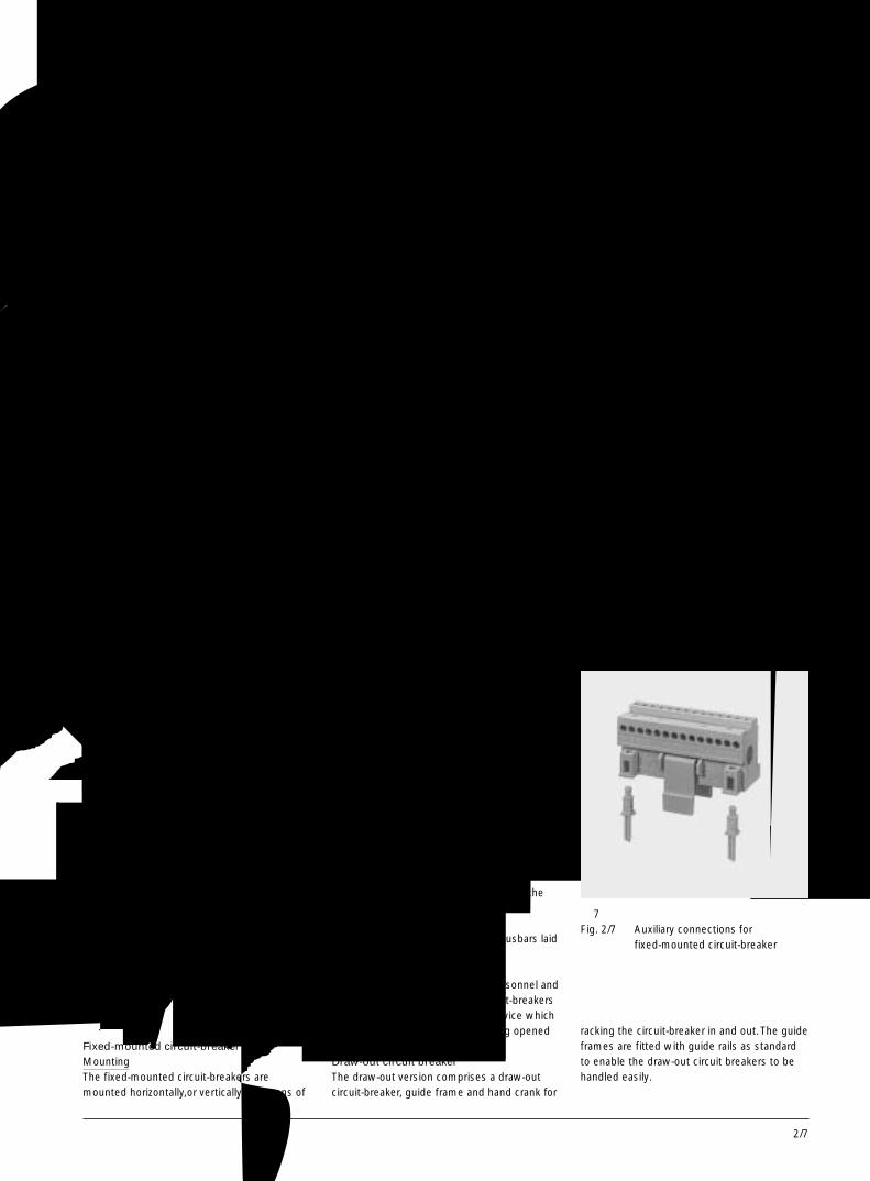
2/7
2
固定式和抽屉式断路器 Fixed-mounted and draw-out circuit-breakers
固定式和抽屉式断路器防止飞弧的保护措施
对于额定电压至AC415V的 3WN6断路器,不需要对垂直母排采用防护措施。
对于额定电压至AC690V的 3WN6断路器,可选用消弧罩盖(可选件),以防止飞弧。
安装于断路器侧面的电气装置也应进行保护。详见第 2/75 页。控制面板
控制面板设计成可由柜门开孔中凸出,这样当柜门关闭后,所有控制装置和显示器仍显而易见,可直接操作。柜门密封框
密封框把凸出开关柜门上的控制面板四周密封住,因此当柜门闭合后,断路器的防护等级能达到 IP 54。
Fixed-mounted and draw-out circuit-breakersProtection against switching gasesFor 3WN6 circuit-breakers with voltages up to415V AC no shielding of vertical bars isrequired.For voltages up to 690 V AC the arcing spacecover (option) can be used for effectiveprotection against arcing.Electrical accessories placed at the side of thecircuit-breaker should be protectedadditionally. See also note on page 2/75.Control panelThe control panel is designed in such a waythat it can project through a cutout in the doorof the cubicle, so that all of the control devicesand indicators remain accessible when the
固定式断路器Fixed-mounted circuit-breakers
主回路连接水平后置(标准型)Main connections at the rear,horizontal (standard)
主回路连接前置,单孔,顶部和底部Main connectionsaccessible from the front,single hole top and bottom
主回路连接前置,双孔,顶部和底部(孔洞按照 DIN43 673标准)Main connections accessible fromthe front double-hole top andbottom (holes acc. to DIN 43 673)
抽屉式断路器Draw-out circuit-breakers
主回路连接水平后置带导轨(标准型)Main connections at the rear,horizontal, with guide rails(standard)
主回路连接垂直后置,顶部和底部Main connectionsat the rear, vertical,top and bottom
主回路连接前置,双孔,顶部和底部(孔洞按照 DIN43673 标准) 较短母排的为单孔
Main connections accessible fromthe front, double-hole top andbottom (holes acc. to DIN 43 673)single-hole with shorter bars;
图 6 主回路连接 / Fig. 2/6 Main connections
door is closed.Door sealing frameThe door sealing frame seals the door of the
cubicle with the control pannel.When the doorof the cubicle is closed protection level IP 54 isthus obtained for the circuit-breaker.
固定式和抽屉式断路器 Fixed-mounted and draw-out circuit-breaker
固定式断路器安装
固定式断路器可用支架水平安装或垂直安装。辅助回路接线(见图 7)
辅助回路接线端子带有销子,可防止接线错误。主回路连接(见图 6)
在标准型中,主回路连接水平后置。这使得断路器可水平连接至系统侧的母排。其他连接方式:-前置单孔安装,适于垂直母排连接-前置双孔安装(孔洞按照DIN43 673标准),适于垂直连接
-后置垂直连接,用于母排安置在系统的侧面。闭锁装置
为了保护操作人员和开关柜,固定式断路器上可装配锁定装置,使得断路器合闸时不能打开开关柜门。抽屉式断路器
抽屉式断路器由抽屉式断路器本体、导向框架和曲柄组成。标准型导向框架中已安装有导轨,使得断路器本体进出方便。
Fixed-mounted circuit-breakerMountingThe fixed-mounted circuit-breakers aremounted horizontally,or vertically by means of
support brackets.Auxiliary connections (see Fig. 2/7)Connection is made by means of singleconnecting leads.The plug connectors havepins that prevent connections to the wronglocations.Main connections (see Fig. 2/6)The main connections are arranged horizontallyon the rear side as standard. This enables theunit to be connected horizontally to busbars onthe system side.Other types of connection:- Single-hole mounting accessible from the
front for vertical busbars- Double-hole mounting accessible from the
front (holes acc.DIN 43 673)for verticalconnection
- Vertical connection at the rear for busbars laidon edge on the system side
Blocking deviceIn order to protect the operating personnel andswitchgear,the fixed-mounted circuit-breakerscan be equipped with a blocking device whichprevents the cubicle door from being openedwhen the circuit-breaker is closed.Draw-out circuit breakerThe draw-out version comprises a draw-outcircuit-breaker, guide frame and hand crank for
racking the circuit-breaker in and out. The guideframes are fitted with guide rails as standardto enable the draw-out circuit breakers to behandled easily.
图 7 固定式断路器的辅助接线端子块Fig. 2/7 Auxiliary connections for
fixed-mounted circuit-breaker
3WN6断路器,至 3200A3WN6 Circuit-Breakers, up to 3200A
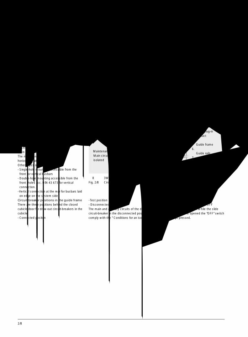
2/8
导向框架 Guide frame
辅助回路接线当断路器移入导向框架时,(如从试验位置至
运行位置)辅助接线端子内的触头自动接通。主回路连接(见图 6)
在标准型中,主回路连接水平后置。其他连接方式:-前置单孔安装,适于垂直母排连接-前置双孔安装,(孔洞按照DIN43 673标准)适于垂直连接
-后置垂直连接,用于母排安置在系统的侧面。断路器在导向框架中的位置
抽屉式断路器在柜门闭合的开关柜内有三个位置:-运行位置-试验位置-退出位置
在退出位置的断路器主回路和辅助回路符合“隔离器条件”(有可见的间隙)。
断路器在移动前必须处于分闸状态。因而要打开曲柄操作孔上的移门,必须同时按下“分闸按钮”。
Auxiliary connectionsThe auxiliary connectins make contactautomatically when the circuit-breaker ismoved into the guide frame (i. e. from testposition to connected position)Main connections (see Fig. 2/6)The main connections are mountedhorizontally at the rear as standardOther types of connection:- Single-hole mounting accessible from the
front for vertical busbars- Double-hole mounting accessible from the
front (holes acc. DIN 43 673)for verticalconnection.
- Vertical connection at the rear for busbars laidon edge on the system side
Circuit-breaker positions in the guide frameThere are three positions behind the closedcubicle door for draw-out circuit-breakers in thecubicle:- Connected positon
● 运行位置主回路和辅助回路都已准备好,可以工作
● Connected positionMain circuit and auxiliary circuitready for operation
● 试验位置主回路隔离,辅助回路可以工作
● Test positionMain circuit isolated andauxiliary circuit ready foroperation
● 退出位置主回路与辅助回路都隔离
● Disconnected positionMain circuit and auxiliary circuitisolated
● 维护位置主回路与辅助回路都隔离
● Maintenance positionMain circuit and auxiliary circuitisolated
1. 柜门Door
2. 辅助接线端子Auxiliary connector
3. 安全挡板Shutter
4. 主回路插入式触头Main plug-incontact
5. 导向框架Guide frame
6. 导轨Guide rails
7. 曲柄Crank handle
图 8 3WN6 抽屉式断路器位置示意图Fig. 2/8 Circuit-breaker positions in the guide frame
- Test position- Disconnected positionThe main and auxiliary circuits of the draw-outcircuit-breaker in the disconnected positioncomply with the " Conditions for an isolator "
(with visible contact gap).The circuit-breaker must be in the OFFposition before it is moved. While the slideover the crank hole is opened the "OFF" switchmust be kept pressed.
3WN6断路器,至 3200A3WN6 Circuit-Breakers, up to 3200A
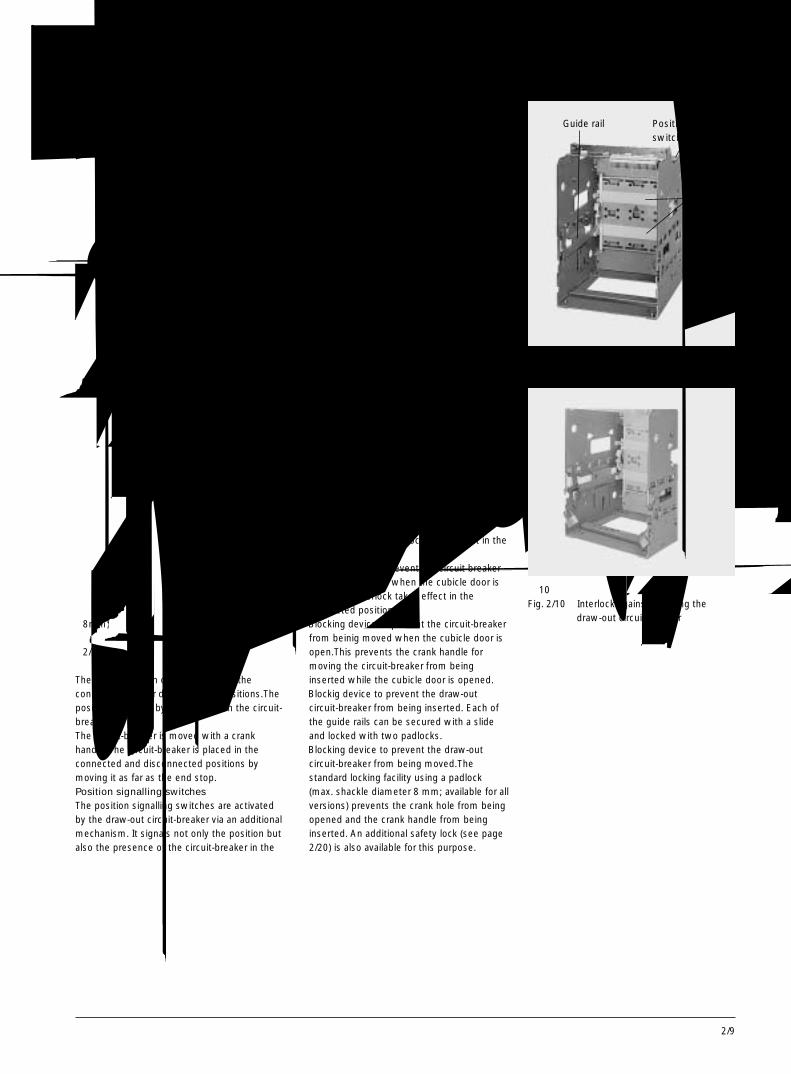
2/9
2
导向框架 Guide frame
只有在断路器处于运行、试验或退出三个位置时才能合上曲柄操作孔。
断路器在导向框架内的移动借助于曲柄来完成。旋转曲柄可使断路器在运行位置和退出位置之间移动。位置信号发送开关
位置信号发送开关由抽屉式断路器借助于一个附加机构来驱动。断路器在导向框架内的位置和状态同时发送。这种开关适合于其他保护装置组成联锁电路。安全挡板
挡板可防止操作人员不小心触及带电的抽屉式触头或母排。挡板有两部分,使顶端和底部进出线侧可以分别打开。这两部分挡板可用两把挂锁锁定在开启或关闭位置。编码系统
为了防止开关柜内具有相同尺寸但所带装置不同的几个断路器互换,抽屉式断路器与导向框架上可配编码系统,此系统最多可防止35台断路器互换。
抽屉式断路器出厂前已由工厂根据额定电流进行了编码(标准配置),以防止此断路器被放置到不同电流额定值的导向框架内。锁定装置
抽屉式断路器可配有下列锁定装置以保护操作人员和开关柜:● 锁定装置用于断路器合闸后防止打开柜门。此联锁在运行位置有效。
● 锁定装置用于柜门打开时防止断路器合闸。此联锁在运行位置有效。
● 锁定装置用于柜门打开时防止移动断路器。这可防止当柜门打开时将曲柄插入曲柄操作孔。
● 锁定装置用于防止抽屉式断路器被塞入导向框架中。每条导轨都可用一个滑块防护并用两个挂锁锁定。
● 锁定装置用于防止抽屉式断路器被移动。标准的锁定装置采用一个挂锁 (锁环最大直径为8mm; 所有类型都具备)以防止曲柄孔被打开和插入曲柄。也可选用其他类型安全锁 (见第2/20 页)。
The crank hole can only be closed in theconnected, test or disconnected positions.Theposition is shown by an indicator on the circuit-breaker.The circuit-breaker is moved with a crankhandle. The circuit-breaker is placed in theconnected and disconnected positions bymoving it as far as the end stop.Position signalling switchesThe position signalling switches are activatedby the draw-out circuit-breaker via an additionalmechanism. It signals not only the position butalso the presence of the circuit-breaker in the
guide frame. This version is suitable forinterlocking circuits with other protectivedevices.ShutterInadvertent touching of current-carrying draw-out contacts or busbars is prevented by ashutter. The shutter has two parts and enablesthe top and bottom connection sides to beopened separately (for verifying dead state)The divided shutter can be locked in the openor closed position and can be fitted with twopadlocks.Coding systemIn order to prevent interchanging of severalcircuit-breakers of the same size with differentequipment inside a cubicle, the draw-outcircuit-breakers and guide frames can beequipped with a coding system. This codingsystem provides mechanical coding for up to35 circuit-breakers.The draw-out circuit-breakers are factory-fitted(as standard) with a rated current coding.This prevents draw-out circuit-breakers beingplaced in a guide frame with different currentrating.Blocking devicesFor the protectin of the operating personneland the switchgear installation, the draw-outversion of the circuit-breakers can be equippedwith the following blocking devices:● Blockig device to prevent opening of the
cubicle door, This interlock takes effect in theconnected positon.
● Blockig device to prevent the circuit breakerfrom being closed when the cubicle door isopen.This interlock takes effect in theconnected position.
● Blocking device to prevent the circuit-breakerfrom beinig moved when the cubicle door isopen.This prevents the crank handle formoving the circuit-breaker from beinginserted while the cubicle door is opened.
● Blockig device to prevent the draw-outcircuit-breaker from being inserted. Each ofthe guide rails can be secured with a slideand locked with two padlocks.
● Blocking device to prevent the draw-outcircuit-breaker from being moved.Thestandard locking facility using a padlock(max. shackle diameter 8 mm; available for allversions) prevents the crank hole from beingopened and the crank handle from beinginserted. An additional safety lock (see page2/20) is also available for this purpose.
图 9 导向框架Fig. 2/9 Guide frame
图10 联锁以防止抽屉式断路器本体被塞入Fig. 2/10 Interlock against inserting the
draw-out circuit-breaker
导轨Guide rail
位置信号发送开关Position signalingswitch
安全挡板Shutter
3WN6断路器,至 3200A3WN6 Circuit-Breakers, up to 3200A

2/10
过电流脱扣器系统介绍 Overcurrent release system-General description
新一代的微处理器控制的电子式过电流脱扣器系统。The new generation of solid-state, micro-processor-controlled overcurrent releasesystems.
过载保护(“a”)Overload protection ("a")
短路短延时保护(“z”)Short-time-delay short-circuit protection ("z")
短路瞬时保护(“n”)lnstantaneous short-circuit protection ("n")
接地故障保护(“g”)Earth fault protection ("g")
图11 B 型和 N 型过电流脱扣器Fig. 2/11 Overcurrent release versions B and N
所有的过电流脱扣器系统都具有如下标准功能试验功能
按下试验按键,借助于脱扣器内部集成的自诊断功能,可以测试过电流脱扣器系统,(测试脱扣器的电路,脱扣线圈和开关机构)。发光二极管工作显示
过电流脱扣器在运行正常时,该发光二极管不停地闪烁绿光。如果运行电流超过过载保护的设定值,发光二极管会快速地闪烁。脱扣原因显示
通过按下查询按键,可查询和显示脱扣原因。该功能为断路器的基本配置之一。µp 故障
如果微处理器发生故障(µp故障),脱扣器上的发光二极管会显示报警信号。过热
如果过电流脱扣器的温度超过85ºC,发光二极管会显示报警信号。
All overcurrent release systems are pro-vided with the following functions asstandard
lntegral test functionPressing the test button the overcurrent re-lease system can be tested by means of anintegral test function with or without trip of thecircuit-breaker (testing the release electronics,the release solenoid and theswitching mechanism).Active LEDperfect functionality of the overcurrent releaseis indicated by a green pulsating LED. lf theoperating current exceeds the threshold valueof the overload protection, the LED starts toflash rapidly.Tripping causeThe tripping cause can be requested anddisplayed locally as standard("Query"pushbutton).µp faultA fault in the microprocessor is indicated by awarning signal (an additional message canalso be activated through an optical coupling).
Overheatinglf the temperature in the overcurrent releaseexceedes 85ºC, a LED signal is activated (anadditional message can also be activatedthrough an optical coupling).
图12 N 型过电流脱扣器上的显示Fig. 2/12 lndicators on overcurrent release
versoin N
● 有关I2t 延时的短路短延时脱扣器用于与下级熔断器实现最佳的选择性配合。
● 带“短时分等控制”(ZSS)功能的短路保护,通过短延时分断来大大的减少配
电系统中的损害,实现区域选择性保护。● 负载脱落 / 负载再接入● 通过 PROFIBUS - DP 实现的通讯功能● 运行电流液晶显示
● Short-time-delay short-circuit release with I2t-dependent delay for better discrimination todownstream fuses.
● Short-circuit protection with "short-timegrading control " (ZSS) for considerable
可选用的附加功能:several additional functions are provided,depending on the version of the overcurrentrelease system, as for instance;
reduction of load and damages in thedistribution system using short delay times.
● load shedding/load take-up● Communication possibility through
PROFIBUS-DP● LCD display for operational current
3WN6断路器,至 3200A3WN6 Circuit-Breakers, up to 3200A

2/11
2
过电流脱扣器系统-B, C/G, V型 Overcurrent release system-versions B, C/G, V
B, C/G型-基本型的过电流脱扣器● “a”过载脱扣运行电流Ir 可从 40~100%×In 按 5%分档进行设置
● “z”短路短延时脱扣动作电流可调Id=1.5 - 2 - 3 - 4 - 5 - 6 - 8 - 10 - 12 ×Ir
延时时间可调td=0,20 (M) - 80 - 150 - 220 - 300 - 400 ms
● “n”短路瞬时脱扣动作电流固定>15 ×In (td=0 ms)
C/G型的其他功能(3 极和 4 极)● “g”接地故障脱扣动作电流Ig = 0.2 - 0.3 - 0.4 - 0.5 - 0.6×In
可选择脱扣和只报警延时时间tg=100 - 200 - 300 - 400 - 500 ms
● N 导线的过载保护 50% 或 100%V型-发电机保护型(“zn”)● 无过载脱扣“a”● 短路短延时脱扣“z”同 B 型● 短路瞬时脱扣“n”同 B 型
Basic release version B, C/G● Overload release "a"
Operating current Ir can be set between 40and 100% ×In in 5% steps
● Short-time-delay short-circuit release "z"
基本型的过电流脱扣器带有短路短延时脱扣功能和众多的其他功能Basic release system features short-timedelay short-circuit release withextensive complements.
图13 B 型“azn”过电流脱扣器Fig. 2/13 Overcurrent release version B“azn”
response currentId=1.5 - 2 - 3 - 4 - 5 - 6 - 8 - 10 - 12 ×Ir
Delay timetd=0,20 (M) - 80 - 150 - 220 - 300 - 400 ms
● lnstantaneous short-circuit release "n"Response current fixed .> 15 ×In (td=0 ms)
additionally for version C/G (3-and 4-pole)● Earth fault release"g"
Response currentIg=0.2 - 0.3 - 0.4 - 0.5 - 0.6 ×In
selectable between trpping and alarm onlyDelay timetg=100 - 200 - 300 - 400 - 500 ms
● Overload protection for N conductor50 or 100%
Generator protection version V ("zn")● Without overload release "a"● Short-time-delay short-circuit release "z"
same as version B, see left● lnstantaneous short-circuit release "n" same
as version B, see left
接地故障保护 Earth-fault protection
描述接地故障脱扣器“g”能检测流过接地端的故
障电流。通过可调的动作延迟时间,可对串联在一起的几台断路器实现时间分级鉴别。
可以设定“故障时只报警”(报警)或“故障时断路器脱扣”(脱扣)。按下查询键,发光二极管会显示脱扣原因。测量方法通过 N 导线上的电流互感器进行矢量求和
N导线的电流被直接测量和估算,以实现对N 导线的过载保护。
过电流脱扣器通过对三相电流和N导线电流进行矢量求和的方式来计算接地故障电流。
对于4极断路器,用于N导线的第4个电流互感器已安装在断路器内部。但对于E型和 J型过电流脱扣器,该电流互感器必须外部安装于进线侧或出线侧。通过变压器星型接地点处的一个电流互感器来直接测量接地故障电流
图14 3极断路器,电流互感器置于N导线上Fig. 2/14 3-pole circuit-breaker, current
transformer in the N-conductor
图16 4 极断路器,电流互感器置于变压器的星型接地线上
Fig. 2/16 4-pole circuit-breaker, currenttransformer at the earthed star pointof the transformer
图15 3 极断路器,电流互感器置于变压器的星型接地线上
Fig. 2/15 3-pole circuit-breaker, currenttransfomer at the earthed star pointof the transformer
电流互感器直接安装在变压器的星型接地点处。
DescriptionThe earth-fault release "g" detects fault cur-rents which flow through earth and couldcause fires in the system. Several circuit-breakers connected in series can be giventime-graded discrimination by means of theadjustable operating delay time.When setting the overcurrent release para-meters it is possible to select between "Alarmonly in case of response " (alarm) or "Circuit-breaker trip in case of response " (trip)By pushing the query button the tripping causecan be displayed on a LED.Measuring methodsVectorial summation with current transformerin the N conductorThe N-conductor current is measured directlyand is evaluated for N-conductor over-loadprotection.The overcurrent release calculates the earth-fault current by means of vectorial summationof the three phase currents and the Nconductor current.ln the case of 4-pole circuit-breakers, the 4thcurrent transformer for the N conductor isinstalled internally. For overcurrent releases Eand J, it must be mounted externally at thefeed in or outgoing side.Direct detection of the earth-fault currentvia a current transformer ar the earthedstar point of the transformerThe current transformer is installed directly atthe earthed star point of the transformer.
3WN6断路器,至 3200A3WN6 Circuit-Breakers, up to 3200A
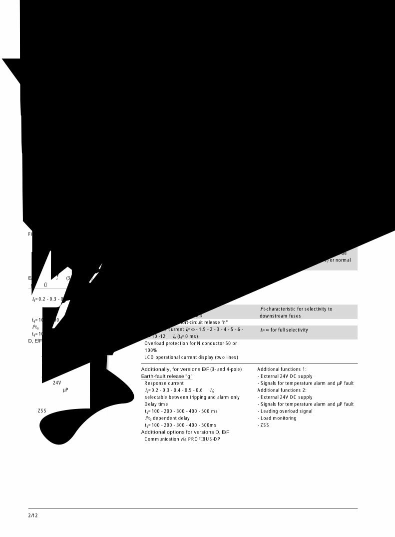
2/12
过电流脱扣器系统- D, E/F型 Overcurrent release systems-versions D, E/F
图17 E/F 型“aznNg”过电流脱扣器Fig. 2/17 Overcurrent release version
E/F“aznNg”
D, E/F型-选择型的过电流脱扣器● “a”过载脱扣运行电流Ir 可从 40~100%×In 按 5%分档进行设置。时滞等级Tc=2 - 3.5 - 6 - 8 - 10 - 14 - 17 - 20 - 24 - 30 s
● “z”短路短延时脱扣动作电流Id=1.25-1.5-2-3-4-5-6-8-10-12 ×Ir
延时时间 td=20(M)0-80-150-220-300-400msI2td有关延时(短路反时限延时)td=80 - 150 - 220 - 300 ms
● “n”短路瞬时脱扣动作电流Ii=∞ - 1.5 - 2 - 3 - 4 - 5 - 6 - 8 - 10 -12×In (td=0 ms)
● N 导线的过载保护50% 或 100%
● 运行电流液晶显示(两行)
Selective overcurrent releaseversions D,E/F● Overload release"a"
Operating current can be set between 40and 100% ×In in 5% stepsTime-lag classTc=2 - 3.5 - 6 - 8 - 10 - 14 - 17 - 20 - 24 - 30 s
● Short-time-delay short-circuit release "z"Response currentId=1.25-1.5-2-3-4-5-6-8-10-12 ×Ir
Delay time td=20(M)-80-150-220-300-400msI2td-dependent delaytd=80 - 150 - 220 - 300 ms
● Instantaneous short-circuit release "n"Response current Ii=∞ - 1.5 - 2 - 3 - 4 - 5 - 6 -8 - 10 -12 ×In (td=0 ms)
● Overload protection for N conductor 50 or100%
● LCD operational current display (two lines)
→取决于电动机负载的机械惯性,可设定Tc对于慢起动(例如取 Tc = 30s)或正常起动(例如取 Tc=10s)均可设定。
→I2t 特性用于与下级熔断器作选择性保护。
→Ii=∞ 用于完全的选择性保护
→ depending on the mechanical interia ofthe motor load the characteristic can beset for slow start (e. g. Tc=30 s) or normalstart (e. g. Tc=10 s)
→I2t-characteristic for selectivity todownstream fuses
→Ii=∞ for full selectivity
选择型的过电流脱扣器系统,带液晶显示和许多附加功能,可关断“n”-脱扣器Selective overcurrent release system, with“n”-release switch-off possibility, LCD-indicator for operating current and manyadditional functions
E/F型的其他功能(3 极和 4 极)“g”接地故障脱扣
● 动作电流Ig=0.2 - 0.3 - 0.4 - 0.5 - 0.6 ×In;可选择脱扣和只报警
● 延时时间tg=100 - 200 - 300 - 400 - 500 msI2tg有关延时tg=100 - 200 - 300 - 400 - 500ms
D, E/F型的附加可选功能● 通过 PROFIBUS-DP 实现通讯● 附加功能 1:-外部的 24V 直流电源-温升过高和 µp 故障的信号发送
● 附加功能 2:-外部的 24V 直流电源-温升过高和 µP 故障的信号发送-过载脱扣的前导信号-负载监控- ZSS
Additionally, for versions E/F (3- and 4-pole)Earth-fault release "g"● Response currentIg=0.2 - 0.3 - 0.4 - 0.5 - 0.6 ×In;selectable between tripping and alarm only
● Delay timetg=100 - 200 - 300 - 400 - 500 msI2tg dependent delaytg=100 - 200 - 300 - 400 - 500ms
Additional options for versions D, E/F● Communication via PROFIBUS-DP
● Additional functions 1:- External 24V DC supply- Signals for temperature alarm and µP fault
● Additional functions 2:- External 24V DC supply- Signals for temperature alarm and µP fault- Leading overload signal- Load monitoring- ZSS
3WN6断路器,至 3200A3WN6 Circuit-Breakers, up to 3200A
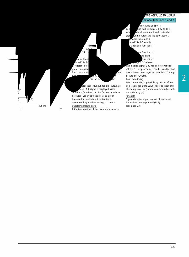
2/13
2
附加功能 1和 2 Additional functions 1 and 2
附加功能 1外部的 24V 直流电源
例如用于参数设置(如设置保护参数和附加功能),当主回路不带电时,使脱扣器显示电流(D,E/F,H,J/K,N/P 型脱扣器)。µp 故障
当微处理器(µp故障)发生故障时,所有型式的过电流脱扣器都会由发光二极管显示故障信号。采用附加功能 1 或 2,故障信号可由光电耦合器输出。微处理器发生故障时,断路器不会脱扣,但一个内部的支路可确保发生短路时短延时脱扣。超温报警
如果过电流脱扣器的温度超过了限定值85ºC,发光二极管会显示“超温”状况。采用附加功能 1 或 2,故障信号可由光耦输出。附加功能 2外部的 24V 直流电源(同附加功能 1)µp 故障(同附加功能 1)超温报警(同附加功能 1)“a”脱扣先导信号
“过载脱扣之前200 ms”的先导信号(经过光偶)可用于关断下级的晶闸管。此脱扣总是在
200ms 后发生。负载监控
通过负载接入和负载脱落(IAW1, IAw2)两个可选的工作值和一个可调的延时时间(td, AW)可实现负载监控。“g”报警
如果出现接地故障,可通过光偶发送信号。短时分级控制(ZSS)(详见第 2/14页)
Additional functions 1External 24V DC supplyFor instance for parameterization (i. e. settingprotection parameters and additionalfunctions), activation of the operational currentdisplay (versions D, E/F, H J/K, N/P) whenthere is no power in the main connections.µP faultIf a microprocessor fault (µP fault) occurs,in allversions an LED signal is displayed. Withadditional functions 1 or 2 a further signal canbe output via an optocoupler, The circuit-breaker does not trip but protection isguaranteed by a reduntant bypass circuit.Overtemperature alarmIf the temperature of the overcurrent release
exceeds the limit value of 85ºC acorresponding fault is indicated by an LED.With additional functions 1 and 2 a furthersignal can be output via the optocoupler.Additonal functions 2External 24V DC supply(see additional functions 1)µP fault(see additional functions 1)Overtemperature alarm(see additional functions 1)Leading signal "a" releaseThe leading signal "200 ms before overloadrelease " (via optocoupler) can be used to shutdown downsteam thyristorcontrollers. The tripoccurs after 200ms.Load monitoringLoad monitoring is possible by means of twoselectable operating values for load input andshedding (IAW1, IAW2) and a common adjustabledelay-time (td, AW)."g" alarmSignal via optocoupler in case of earth-faultShort-time grading control (ZSS)(see page 2/14)
3WN6断路器,至 3200A3WN6 Circuit-Breakers, up to 3200A

2/14
过电流脱扣器系统- N型和 P型 Overcurrent release systems-versions N and P
图 18 P 型“aznNg”过电流脱扣器;N 型“aznN”过电流脱扣器(无接地故障保护功能)
Fig. 2/18 Overcurrent release verdion P “aznNg”;Overcurrent release version N “aznN”(without earth-fault protection)
N和 P型 -完全选择型的过电流脱扣器
● “a”过载脱扣运行电流Ir 在 40~100%×In 之间可设置。
● 时滞等级 Tc 在 2~30s之间可设置● “z”短路短延时脱扣动作电流Id 在 1.25×Ir~40 kA之间可设置延时时间 td 在 20 ms-400 ms之间可设置I2td 有关延时 td 在 80-300ms之间可设置
● “n”短路瞬时脱扣动作电流Ii 可设定至 50 kA (尺寸等级 I)或 65 kA(尺寸等级 II) (td=0 ms)
● N 导线的过载保护运行电流IN 在 20~100%×In 之间可设置
● 运行电流液晶显示(两行)● 通过脱扣器面板上的键盘或手持式编程装置或通过通讯(远距离参数设置),可在用户友好的菜单界面上设置保护参数,可设置电流绝对值。
● 外部的 24V 直流电源Fully selective versions N and P● Overload release "a" Operating current Ir can be set between40 and 100% ×In
Time-lag class Tc can be set between2 and 30 s
● Short-time-delay short-circuit release "z"Response current Id can be set between 1.25 ×Ir and 40 kADelay time td can be set between 20 and400 msI2td -dependent delay td can be set between 80and 300 ms
● Instantaneous short-circuit release "n"Response current Ii selectable 50 kA (size I)or 65 kA (size II) (td=0 ms)
● Overload protection for N conductorOperating current In can be set between 20and 100% ×In
● LCD operational current display (two lines)● User-friendly menu-driven setting of
protection parameters directly in absolute
→I2t 特性用于与下级熔断器作选择性保护。
→至 50/60 kA 可实现完全的选择性保护
→I2t-characteristic for selectivity todownstream fuses
→ Full selectivity up to 50/65 kA
P型过电流脱扣器的其他功能“g”接地故障脱扣
● 动作电流Ig 在 20%×In 至 1200A(最大值)之间可设定可选择脱扣和只报警
● 延时时间 tg 可从 100~500 ms之间设定I2tg 有关延迟时间 tg 可在 100~500 ms 之间设定
N型和 P型的其他功能:● 通过 PROFIBUS-DP 通讯● 能量管理(测量模块)● 附加功能 1:-外部的 24V 直流电源-超温报警信号和 µp 故障信号发送
● 附加功能 2-外部的 24V 直流电源-超温报警信号和 µp 故障的信号发送-过载先导信号发送-负载监控- ZSS 功能
Ampere values via release system keyboardor hand-held control unit or throughcommunication (remote parameterization)
● External 24 V DC supply for activating theLCD display (parameterization)
Additionally for version PEarth-fault release "g"● Response current Ig can be set from 20% ×In up to 1200 A max.Selectable between tripping and alarm only
● Delay time tg can be set between100 and 500msI2tg -dependent delay tg can be set between100 and 500 ms
Further options for versions N and P:● Communication via PROFIBUS-DP● Energy managerment (measurinig module)
● Additional functions 1:- external 24 V DC supply (as standard)- Signals for overtemperature alarm and µpfault
● Additional functions 2:- external 24V DC supply (as standard)- Signals for overtemperature alarm and µpfault- Leading overload signal- Load monitoring- ZSS
完全选择型的过电流脱扣器,带可设定的电流至 40/50 kA的短路脱扣器,带运行电流液晶显示和许多附加功能;可实现能源管理。Fully selective overcurrent release, withsettable short-circuit release up to 40/50kA, with LCD operational current displayand many additional functions; Energymanagement
带短时分级控制 ”ZSS”的短路保护 Short-circuit protection with “Short-time grading control” (“ZSS”)
描述ZSS功能提供了完全的选择性保护,即在配
电系统中,无论短路发生在何处,也无论分级的程度如何,只要发生短路故障,断路器会在极短的时间内 tZSS=50ms脱扣。由于极短的脱扣时间,一旦发生短路后,影响系统的负载和损害可被显著的减少。
采用ZSS功能以后,受到短路电流影响的每台断路器会检测其下级的断路器,以找出短路是否还影响到其下级断路器。
DescriptionThe ZSS function provides full selectivity witha very short delay time tZSS= 50ms,irrespectiveof the grading level and of where,in thedistribution system,the short-circuit hasoccurred.Due to the shorter breaking time,the loads anddamage affecting the switchiing system in theevent of a short-circuit can be significantlyreduced.If the ZSS function is engaged,each circuit-breaker affected by a short-circuit checks thedirectly downstream circuit breakers,to findout if the short-circuit has affected lowerlevels.
图 19Fig. 2/19
3WN6断路器,至 3200A3WN6 Circuit-Breakers, up to 3200A

2/15
2
过电流脱扣器系统- H, J/K型 Overcurrent release systems-versions H, J/K
图 20 J/K 型“aznNg”过电流脱扣器.Fig. 2/20 Overcurrent release version J/K “aznNg”
H, J/K型 -“黑匣子式”过电流脱扣器● “a”过载脱扣运行电流Ir 可在 40%~100%×In 之间设置。时滞等级 Tc 在 2~30s之间设置
● “z”短路短延时脱扣动作电流Id 可在 0.5~12×In 之间设置延时时间 td 在 20-400 ms之间可设置I2td 有关延时时间 td 可在 80-300 ms之间设置
● “n”短路瞬时脱扣动作电流Ii可在0.5~12×In之间设置(td=0 ms)还可选择Ii=∞
● N 导线的过载保护运行电流IN 可在 20%~100%×In 之间设置
● 脱扣器的设置及其安全(脱扣器上无旋钮)● 采用手持式编程装置或采用通讯方式(远距离参数设置),可在用户友好的菜单界面上设置保护参数。
Black-Box version H, J/K ("azn","azng")● Overload release"a"
Operating current can be set between 40and 100% ×In
Time-lag class Tc can be set between2 and 30 s
● Short-time-delay short-circuit release "z"Response current In can be set between 0.5and 12 ×In
Delay time td can be set between20 and 400 msI2td- dependent delay td can be set between80 and 300 ms
● Instantaneous short-circuit release "n"Response current Ii can be set between 0.5and 12 ×In and also turned-off i.e. Ii=∞ (td=0ms)
● Overload protection for N conductorOperating current In can be set between 20and 100% ×In
● Safety oriented operating philosophy (norotary selectors on the release unit)
● User-friendly menu-driven setting of
选择型的黑匣子式过电流脱扣器带有可关断“n”脱扣器的功能,并有许可附加功能可选择,并且参数的设置和保存非常安全;虽然功能齐全但价格却很适中。Selective Black-Box overcurrent release with“n” release switch-off possibility, manyadditional functions and safety-orientedoperating philosophy; full functionality at anaffordable price
J/K型过电流脱扣器的其他功能(3 极和 4 极)“g”接地故障脱扣
● 动作电流Ig 可在 20%×In 至 1200A(最大值)之间设置,可选择脱扣和只报警
● 延迟时间 tg 可从 100~500 ms之间设置H,J/K型脱扣器的其他可选项:● 通过 PROFIBUS-DP 通讯● 附加功能 1:-外部 24 V 直流电源(标准型)-超温报警信号和 µp 故障信号发送
● 附加功能 2-外部 24V 直流电源-超温报警信号和 µp 故障信号发送-过载脱扣先导信号发送-负载监控- ZSS 功能
Additionally for version J/K (3 and 4-pole)Earth-fault release "g"Response current Ig can be set from 20% ×In
up to 1200 A max.Selectable between tripping and alarm only● Delay time tg
can be set between 100 and 500 msFurther options for versions H, J/K:
→取决于电动机负载的机械惯性,对于慢起动(例如取 Tc=30s)或正常起动(例如取 Tc=10s)均可设定 Tc。
→I2t 特性用于与下级熔断器作选择性保护。
→Ii=∞ 用于完全的选择性保护 (Icu=Ics=Icw)
→ depending on the mechanical interia ofthe motor load the characteristic can beset for slow start(e. g. Tc=30 s) or normalstart (e. g. Tc=10 s)
→I2t-characteristic for selectivity todownstream fuses
→Ir=∞ for full selectivity (Icu=Ics=Icw,smallest value counts)
- external 24V DC supply- Signals for overtemperature alarm and µP-fault- Leading overload signal- Load monitoring- ZSS
手持式编程器 Hand-held control unit
描述手持式编程器经由一根电缆和一个插入式匹
配器与过电流脱扣器相连。外部的直流24V电源可接在匹配器上以给过
电流脱扣器供电。功能
手持式编程器可将设置好的保护参数输入至H,J/K,N和P型脱扣器,也可从过电流脱扣器中读取参数的设置值。
手持式编程器可从一台断路器中读出设置参数,然后储存起来并输入至另一台断路器的过电流脱扣器中。
DescriptionThe hand-held control unit is connected to theovercurrent release via a cable and a plug-in
adapter.An external 24V DC power supply can beconnected to the adapter to activate theovercurrent release.FunctionsChecking and inputting the protectinparameters for the overcurrent releaseversoins H, J/K, N and P.Activation and deactivation of response valuesfor overcurrent release versions D, E/F, H/J/K,N and P.The parameter values set for a given circuit-breaker can be read and stored in the hand-held control unit and subsequently be inputtedinto input for another overcurrent release. 图 21 手持式编程器
Fig. 2/21 Hand-held control unit
protection parameters in absoluteAmpere values via hand-held control unit orthrough communication (remoteparameterization)
● Communication via PROFIBUS-DP● Additional functions 1:
- external 24V DC supply (as standard)- Signals for overtemperature alarm and µP-fault
● Additional functions 2:
3WN6断路器,至 3200A3WN6 Circuit-Breakers, up to 3200A

2/16
功能Function
基本功能 / Basic functions
过载保护 过载反时限脱扣 ”a” 工作电流Ir 的设置:40%-100% In 5%分级 Setting of Ir from 40% to 100% In 5% gradingOverload protection 用于三相保护 分级可编程 Grading freely programmable
Inverse-time 时滞等级 TC=6×Ir 时的分闸时间; Time-lag class TC=opening time at 6 ×In
overload rdlease“a” 固定设置 TC fixed setting TC
for the phases 热记忆 ”Thermal” memory断相灵敏(可开关) Phase failure sensitivity (switchable)
用于 N 导线保护 工作电流IN 的设置 Setting of operating current IN
for the N conductor1) N导线的时滞等级 TC 与三相保护时的 TC 相同 Time-lag class TC of the N conductor same as for the phases
短路保护 短路短延时脱扣 ”z” 动作电流Id 的设置 Setting of response current Id
Short-circuit Short-time-delayprotection short-circuit 延迟时间 td 的设置 Setting of delay time td
release ”z” 有关I 2td 延时,延迟时间 td With I 2td dependent delay; delay time td
短路瞬时脱扣 ”n” 动作电流Ii 的位置 Setting of response current Ii
Instantanous short-circuit release ”n”
接地 接地故障脱扣 ”g”1) 动作电流Ig 的位置 Setting of response current Ig
故障保护 Earth-fault 延迟时间 tg 的设置 Setting of delay time tg
Earth-fault protection release“g”1) 带有关I 2td 延时,延迟时间 td With I 2td dependent delay; delay time td
由液晶显示器显示 / Display by LCD 工作电流显示/Operational current display
由发光二极管显示 工作显示 当过电流脱扣器得电时,发光二极管闪烁 LED flashes when overcurrent release is activatedDisplay by LED Operating display
脱扣显示 ”a” 脱扣 ”a” releaseTripped display ”z/n” 脱扣 ”z/n” release
”z” 脱扣 ”z” release”n” 脱扣 ”n” release”N” 脱扣 N ”N” release”g” 脱扣/报警 ”g” release/alarm
报警显示 µp 故障 µp faultAlarm display 温度> 85ºC θ, temperture > 85ºC
三相不平衡> 50% Phase imbalance> 50%随意可选信号 Freely selectable signal
测试 内部自身测试,发光二极管显示 Internal self-test with LED display
Testing 从测试插座 X3 处接入测试设备 Connection of the testing device to the test socket X 3
基本特性 / Basic features信号发送触头(1NO) 合闸准备就绪 断路器可以被安全合闸 Circuit-breaker can be safely switched onSignalling contacts (1NO) Readiness to close
脱扣信号发送开关 在带/不带机械重合闸闭锁的 ”a” Latching: effective after”a”, “z”, “n”, “g”2)
Tripped signalling switch release with/without mechanical reclosing lockout“z”, “n”, “g”2)型脱扣器发生脱扣后动作
附加功能 / Additional features
信号通过光耦输出 附加功能 1 外部 24V 直流电源,可用于参数预置 External 24V DC supply for parameterization
Signals via optocoupler outputs Additional functions 1 µP 故障 µP fault温度>85º θ, temperature >85ºC与三相不平衡组合在一起 combined with phase imbalance
附加功能 2 外部 24V 直流电源,可用于参数预置 External 24V DC supply for parameterizationAdditional µP 故障 µP faultfunctions 2 温度>85º θ, temperature >85ºC
与三相不平衡组合在一起 combined with phase imbalance”a” 脱扣的前导信号(脱扣之前 Leading signal of ”a” tripping (200 ms before200ms)/负载脱落 release)/load shedding负载监控;响应值 50-150%,1-15s Load monitoring; response value 50 to 150%, 1 -15“g” 报警 “g”alarm3WN 与 3WS 之间的短时分级控制(ZSS) Short-time grading control (ZSS) between 3WN and 3WS
通过 PROFIBUS-DP 进行通讯 / Communicaton via PROFIBUS-DP
数据传送 通讯模块 需带附加功能 2 的脱扣器和 DP/ In combination with additional functions 2 and DP/Data transmission Communication 3WN6 接口装置(订货号 3RK10 00- 3WN6 interface (Order NO.3RK 10 00-0JC80-0BA1).
module 0JC80-0BA1)
数据传送和记录测量值 测量模块 需带附加功能 2 的过电流脱扣器和 DP/ In combination with additional functions 2 and DP/Data transm. and meas. Measurement 3WN6 接口装置(订货号 3RK10 00- 3WN6 interface (Order NO.3RK 10 00-0JC80-0BA1).values recording module 0JC80-0BA1)
功能一览表 Function overview of overcurrent release system
1) 对于带三相不平衡负载的 3 极断路器,需要一个附加的电流互感器。对于 4 极断路器,一个 N 线电流互感器已装于其内部。
2) ”g” 脱扣当过电流脱扣器设定在“脱扣”位置时发生。
1) With 3-pole circuit-breakers with asymmertrical phase load, an additionalcurrent transfromer is needed.With 4-pole circuit-breakers, an N-conductor current transformer is built-in
2) ”g” trip occurs in case of “trip” setting on overcurrent release.
3WN6断路器,至 3200A3WN6 Circuit-Breakers, up to 3200A
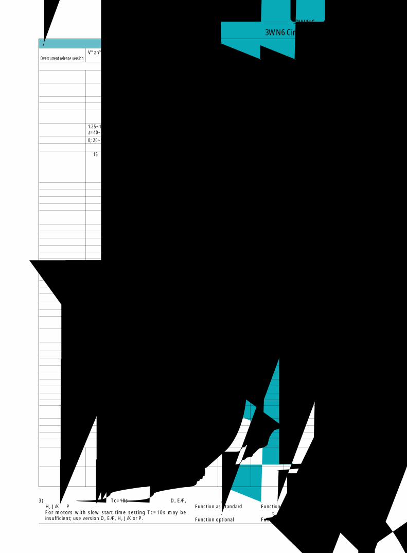
2/17
2
过电流脱扣器类型 V”zn” B”azn” C/G”aznNg” D”aznN” E/F”aznNg” H”aznN” J/K”aznNg” N”aznN” P”aznNg” Overcurrent release version
● ● ● ● ● ●
● ●
10 s 3) 10 s3) 2 to 30 s 2 to 30 s 2 to 30 s 2 to 30 s 2 to 30 s 2 to 30 s
● ● ● ● ● ●
× × × × ● ● ● ●
50 or 100% 50 or 100% 50 or 100% 20~100% 20~100% 20~100% 20~100%
1.25~12 ×Ir 1.5~12 × Ir 1.25~12 ×Ir 1.25~12 ×Ir 1.25~12 ×Ir 0.5~12 ×Ir 0.5~ 12×Ir 1.25×Ir ~ 1.25×Ir ~Ir=40~100%In 40kA 40kA
0; 20~500ms 0; 20~400ms 0; 20~400ms 20~400ms 20~400ms 20~400ms 20~400ms 20~400ms 20~400ms80~300ms 80~300ms 80~300ms 80~300ms 80~300ms 80~300ms
> 15×In > 15×In > 15×In > 1.5~12 × In > 1.5~12 × In > 1.5~12 ×In > 1.5~12 × In Size I: Size I:and Ii=∞ and Ii=∞ and Ii=∞ and Ii=∞ up to 50kA up to 50kAwith setting with setting with setting with setting Size II: Size II:Ii=∞ Ii=∞ Ii=∞ Ii=∞ up to 65kA up to 65kAIcu=Ics=Icw Icu=Ics=Icw Icu=Ics=Icw Icu=Ics=Icw
0.2~0.6×In 0.2~0.6×In 20%In ~1200A 20%In~1200A100~500 ms 100~500 ms 100~500 ms 100~500 ms
100~500 ms 100~500 ms 100~500 ms● ● ● ●
● ● ● ● ● ● ● ● ●
● ● ● ● ● ● ● ●
● ● ●
● ● ● ● ● ●
● ● ● ● ● ●
● ● ● ● ● ● ●
● ● ●
● ● ● ● ● ● ● ● ●
● ●
● ●
●■ ●■ ●■ ●■ ● ●
● ● ● ● ● ● ● ● ●
● ● ● ● ● ● ● ● ●
● ● ● ● ● ● ● ● ●
● ● ● ● ● ● ● ● ●
▲ ▲ ▲ ▲ ● ●
▲ ▲ ▲ ▲ ▲ ▲
▲ ▲ ▲ ▲ ▲ ▲
▲■ ▲■ ▲■ ▲■ ▲ ▲
▲ ▲ ▲ ▲ ● ●
▲ ▲ ▲ ▲ ▲ ▲
▲ ▲ ▲ ▲ ▲ ▲
▲■ ▲■ ▲■ ▲■ ▲ ▲
▲■ ▲■ ▲■ ▲■ ▲ ▲
▲■ ▲■ ▲■ ▲■ ▲ ▲
▲ ▲ ▲
▲ ▲ ▲ ▲ ▲ ▲
▲ ▲ ▲ ▲ ▲ ▲
▲ ▲
● 标准配置功能 ■ 由手持式编程装置选择/设置Function as standard Function selectable/adjustable with hand held unit▲ 可选附加功能 ×当 td 设定为 20ms时,该功能才有效Function optional Function active when td is set to 20 ms
功能一览表 Function overview of overcurrent release system
3) 对于起动时间较长的电动机,Tc=10s可能不够,应采用D, E/F,H, J/K 或 P 型。For motors with slow start time setting Tc=10s may beinsufficient; use version D, E/F, H, J/K or P.
■ ■
3WN6断路器,至 3200A3WN6 Circuit-Breakers, up to 3200A

2/18
通讯模块 Communication module
要通过PROFIBUS-DP通讯,过电流脱扣器要加装一个内部通讯模块(订货号后应加 Z =F01)。数据通过一根电缆连接线(3m 长,随 DP/3WN6 一起供货)传送至外部接口 DP/3WN6 (详见“具有通讯能力的断路器”一章)。
该接口将数据转换后传送至 PROFIBUS -DP。根据过电流脱扣器类型和断路器的配置,可通讯以下数据。● 模拟检测量相电流IL1, IL2, IL3, Imax 和Imin,N 导线电流 IN,接地故障电流Ig
● 事故信号上次脱扣类型(a,z,n,g,N),µp 故障超温报警,相不平衡负载脱落、负载接入"a" 脱扣前导信号
● 运行状态断路器处于合闸 / 分闸状态,合闸准备就绪信号,分励或欠电压脱扣器的状态,储能机构已储能,抽屉式断路器的位置(试验或运行),过电流脱扣器的测试。
● 远距离参数设置● 读出配置数据:保护功能的设置
● 断路器的额定电流,极数
断路器的识别号● 诊断数据前一刻钟的电流平均值
● 远距离控制使断路器分闸和合闸(只对带有电气合闸和分励脱扣器的断路器而言)。远距离参数设置
可通过数据总线远距离设定附加功能和保护功能。过电流脱扣器会检查保护参数值是否有效。
For communication via PROFIBUS-DP theovercurrent releases are additionally equippedwith an internal communication module (forthis the addition Z=F01 should be indicated inthe Order No.). Data are transferred to anexternal interface DP/3WN6 via a cable link(3m long cable is supplied). This interfacetranslates the data for PROFIBUS-DP, Thefollowing data are available, depending on theovercurrent release version and theconfiguration of the circuit-breaker:● Analog measured values:
Phase currents IL1, IL2, IL3, Imax and Imin,N conductor current IN,Earth-fault current Ig
● Event signals:Last trip (a,z,n,g,N),µP fault,Temperature alarm,
Phase imbalance,Load shedding, load input, overload
● Operating states:Breaker closed/open,Ready-to-close signal,State of shunt or undervoltage release,Stored-energy mechanism charged,Position (test or connected) ofdraw-out circuit-breaker,overcurrent release test
● Remote parameterization● Reading configuration data:
Setting of protective functions● Rated current of circuit-breaker,
Number of poles,Circuit-breaker identification number
● Diagnostics data:Current mean over last quarter-hour
● Remote control:Opening and closing of circuit-breaker (onlyfor circuit-breakers with electrical closing andshunt-trip)
Remote parameterizationSetting of additional functions and theprotective functions can be effected via bus.The overcurrent release checks that theprotection parameter values are permissibleand valid.
测量模块 Measuring module
N型和P型过电流脱扣器还可附加一个测量模块(订货号后Z=F05替代Z=F01)。测量模块包括带测量功能的通讯模块和外接电压互感器。除了电流值外,还可获得电压和频率等数据,可获得下列参数:● 电压 UaktL, UmaxL, UminL
(每隔 15分钟交替显示最大值和最小值)ULL1, ULL2, ULL3 (线电压)
● 频率 fakt, fmax, fmin
(每隔 15分钟交替显示最大值和最小值)● 功率因数 cos ϕ● 有功功率 P● 无功功率 Q● 视在功率 S● 有功能量 W● 相序
上述值可用于能源管理,通过连接 / 分断负载可避免负载峰值。还可传输脱扣器的下述信号和保护功能:● 电压和电流的相不平衡● 欠电压 / 超电压● 频率过低 / 频率过高● 能量反流
上述数据还可在过电流脱扣器上显示出来。测量模块的电子互感器需外部安装在35mm
导轨上。电压互感器随测量模块一起提供。测量模块不能改装。
Overcurrent release versions N and P can beadditionally equipped with a measuringmodule (Order No. supplement Z=F05 insteadof Z=F01). The measuring module consists ofthe communication module with additionalmeasuring functions and external voltagetransformers. In this way, beside currentvalues, voltage and frequency data can also beobtained and following operational valuesbecome additionally available:● Voltage UaktL, UmaxL, UminL
(max. and min. values over 15 minute iterval)ULL1,ULL2,ULL3
(conductor-to-conductor voltage)● Frequency fakt, fmax, fmin
(max. and min. values over 15 minute iterval)● Power factor cos ϕ● Active power P● Reactive power Q● Apparent power S● Active work W● Direction of phase rotationThese values can be used for energymanagement,as expensive load peaks can beavoided by connecting/disconnecting theloads.The following signals and protection functionswith release are also available:
● Phase imbalance of voltage and current● Undervoltage/Overvoltage● Underfrequency/Overfrequency● Inverse energy flowThe data can also be displayed locally on theovercurrent release unit.The voltage transformers of the measuringmodule are mounted externally.Installation isdone on a 35mm top hat rail.The voltagetransformers are included in the scope ofsupply of the measuring module.Themeasuring module cannot be retrofitted.
3WN6断路器,至 3200A3WN6 Circuit-Breakers, up to 3200A
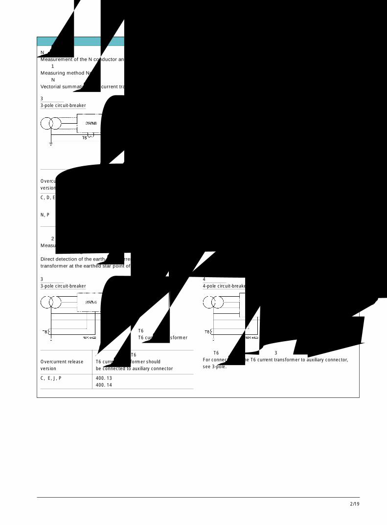
2/19
2
电流互感器的连接 Connection of the current transformer
N导线和接地故障电流的测量Measurement of the N conductor and earth-fault currents方法 1Measuring method No.1通过N导线上的电流互感器进行矢量求和Vectorial summation with current transformer in the N conductor
3 极断路器3-pole circuit-breaker
4 极断路器4-pole circuit-breaker对于 4极断路器,用于N导线的第 4个电流互感器已安装于断路器的内部。In the case of 4-pole circuit-breakers, the 4th current transformerfor the N conductor is installed intermally.例外:Exception:若采用 E 型过电流脱扣器,第 4 个电流互感器必须外部安装在 N 导线上。For E version overcurrent releases, the current transformer must bemounted externally in the N conductor.
T5 电流互感器T5 current transformer
过电流脱扣器类型 连接电流互感器 T5 的辅助接线端子Overcurrent release T5 current transformer shouldversion be connected to auxiliary connector
C, D, E, H, J 400. 13400. 14
N, P 300. 1300. 2
过电流脱扣器类型 连接电流互感器 T5 的辅助接线端子Overcurrent release T5 current transformer shouldversion be connected to auxiliary connector
E, J 400. 13400. 14
方法 2Measuring method No.2通过变压器星型接地点处的电流互感器直接检测接地故障电流Direct detection of the earth-fault current via a currenttransformer at the earthed star point of the transformer
3 极断路器3-pole circuit-breaker
4 极断路器4-pole circuit-breaker
T6 电流互感器T6 current transformer
T6 电流互感器T6 current transformer
过电流脱扣器类型 连接电流互感器 T6 的辅助接线端子Overcurrent release T6 current transformer shouldversion be connected to auxiliary connector
C, E, J, P 400. 13400. 14
有关 T6 电流互感器的连接,请见 3 极断路器。For connection of the T6 current transformer to auxiliary connector,see 3-pole.
3WN6断路器,至 3200A3WN6 Circuit-Breakers, up to 3200A

2/20
分闸和合闸开关“机械合闸按钮”
在标准形式中,机械合闸开关是一个按钮。当带电气合闸功能时,此“机械合闸”开关上装有一个密封盖。也可用一个安全锁(CES、BKS、IKON)来代替此按钮。如果钥匙旋至“0”位置取出,断路器就无法再次机械合闸。“电气合闸”按钮
使用“电气合闸”按钮可方便地安装外部电气锁定设备。此按钮上也可安装密封盖。“机械分闸”按钮
在标准形式中,机械操作的分闸开关是一个按钮,上面可用一个附加的密封盖保护,以防无关人员操作。安全锁
如果钥匙旋至分闸位置取出后,断路器就无法再次合闸。然后,可用这把钥匙去打开另一个断路器的闭锁。急停按钮
使用此蘑菇头按钮锁定在分闸位置时,断路器就无法合闸,除非旋动蘑菇头使闭锁打开。防止合闸锁定装置
在锁定装置的折板上有一个突出物盖住“电气合闸”按钮,并把“机械分闸”按钮卡在分闸位置上。此锁定装置可用 4 把挂锁保护。CASTELL,FORTRESS 或 KIRK-KEY 锁
对于这些锁定装置备有一个安装组件。此锁必须从生产厂家处获得。当此锁受激时,断路器即受阻无法合闸。
断路器在分闸位置满足“隔离器条件”。用于CASTELL、FORTRESS 或 KIRK - KEY 锁的带折板的附加锁定装置可防止插入钥匙。此装置可用4 把挂锁保护。
ON and OFF switches"Mechanical ON" buttonIn its standard form, the mechanicallyoperating ON switch is a pushbutton switch.When it is operated with electrical closing, the"mechanical ON" switch is fitted with a sealingcap. A safety lock (CES, BKS, IKON) is alsoavailable instead of the pushbutton switch. Ifthe key is removed in the "0" position thecircuit-breaker can no longer closemechanically.
分闸、合闸与锁定装置 Opening, closing and Interlocking device
"Electrical ON" buttonThe "Electrical operating ON" button isintended for operational closing. Externalelectrical locking devices can be easilymounted using the "electrical ON" button. Asealing cap is also available for thispushbutton."Mechanical OFF" buttonIn its standard form, the mechanicallyoperating OFF switch is a pushbutton switch.An additional sealing cap protects the switchfrom unauthorized use.The followin can be supplied instead of thisOFF switch:Safety lockIf the key is removed in the OFF position, thecircuit-breaker can no longer close. This keycan then be used to unlock another circuit-breaker.EMERGENCY-STOP pushbuttonThis mushroom-shaped pushbutton latches inthe OFF position when it is pushed. Thecircuit-breaker cannot be closed again until thepushbutton has been unlatched by rotating themushroom head.Locking facility against closingA protrusion in the flap of the locking facilitycovers the "electrical ON" button and retainsthe "mechanical OFF" button in the OFFpusition. The locking facility can be securedwith up to 4 padlocks.CASTELL, FORTRESS or KIRK-KEY lockThese locking devices are prepared with anassembly kit. The lock must be obtained fromthe manufacturer. Then the lock is activated,the circuit-breaker is blocked and cannot close.The "conditions for an isolator" are fulfilled inthe OFF position. An additionally availablelocking facility with a flap for a CASTELL,FORTRESS or KIRK-KEY lock prevents theinsertion of a key. This device can be securedby up to 4 padlocks.
1 操作次数计数器Operating cycle counter
2 过电流脱扣器透明面罩Transparent cover for overcurrent release
3 电动机开关Motor switch
4 机械合闸按钮上的密封盖Sealing cap over mechanical ON button
5 替代分闸按钮的急停按钮EMERGENCY-STOP button in placeof OFF button
6 防止打开曲柄孔的安全锁Safety lock against openingof the crank hole
7 防止打开曲柄孔的挂锁Padlock against opening of the crank hole
8 替代机械合闸按钮的安全锁Safety lock in place of mechanicalON button
9 机械分闸与电气合闸按钮上的锁定装置Locking device for mechanical OFFand electrical ON buttons
10 CASTELL、FORTRESS 或KIRK-KEY 锁的安装位置Location for CASTELL, FORTRESSor KIRK-KEY lock
图 22 分闸、合闸和锁定装置Fig. 2/22 Opening, closing and interlocking
devices
3WN6断路器,至 3200A3WN6 Circuit-Breakers, up to 3200A
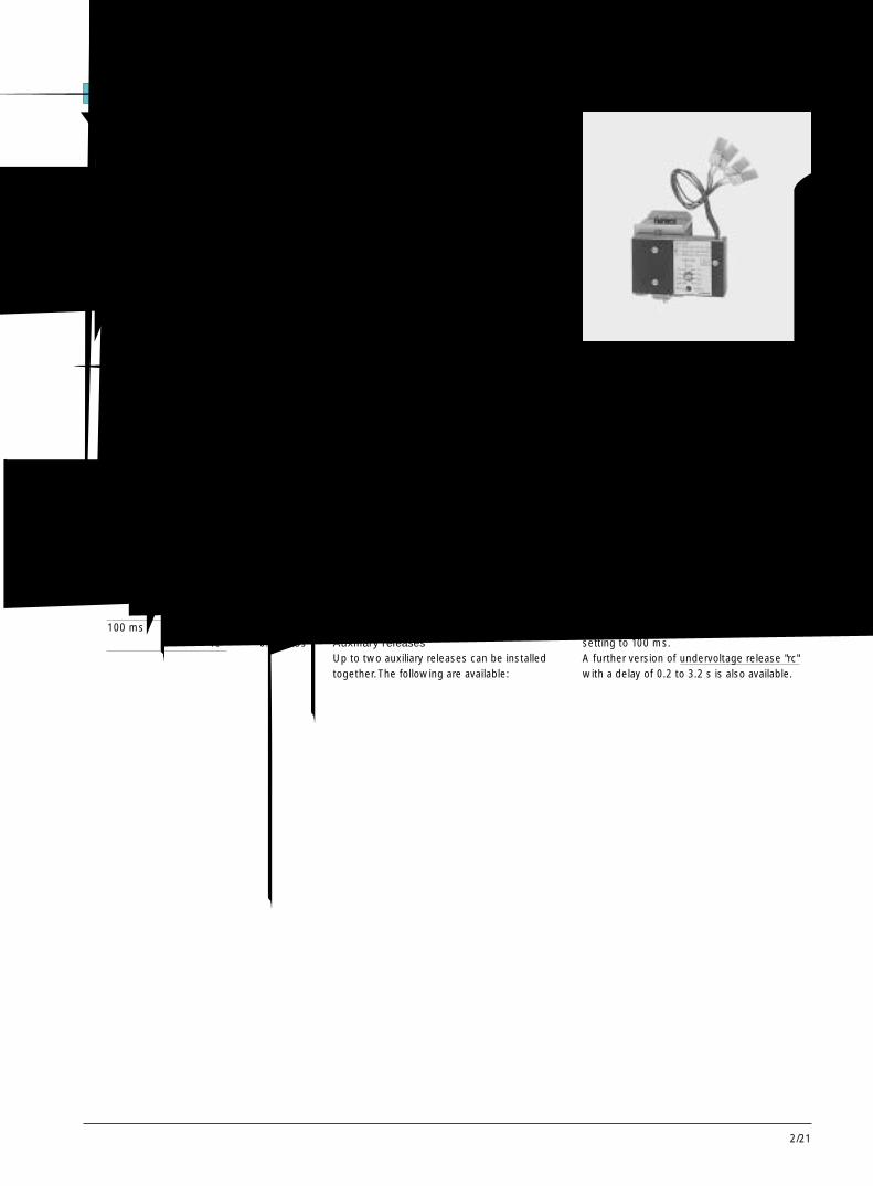
2/21
2
防止抽屉式断路器移动的锁定装置采用一个或多个挂锁可防止曲柄孔被打开或
插入曲柄。也可采用其他类似安全锁把曲柄孔锁定在某一位置上(钥匙可取下)和防止导向框架内的断路器被移动。柜门内的锁定装置
嵌在柜门内的安全锁可防止断路器合闸。对于抽屉式断路器,此锁定装置只在运行位置有效。信号通过钢缆传送。过电流脱扣器的透明面罩
此透明面罩可加装密封铅条,这样参数设置很安全,有效的防止了未经许可触摸。留出的小孔使查询和测试按键可操作。一个可旋转的折页盖住了过电流脱扣器的整个操作面板。电动机开关
通过一个附加(另订)的电动机开关,在一次合闸操作后,可中断自动储能。没必要为了维护而切断控制电压。操作计数器
3WN6断路器可配备一个5位数的操作计数器。辅助脱扣器
断路器最多能同时配备两个辅助脱扣器,有以下几种选择:1 个分励脱扣器或 1 个欠电压脱扣器或两个分励脱扣器或 1 个分励脱扣器+ 1 个欠电压脱扣器
分励脱扣器“f”可持续通电,以确保断路器被锁住,防止断路器误合闸。
分励脱扣器储能装置可确保当控制电压消失后,仍可使断路器脱扣。
欠电压脱扣器“r”是瞬时动作的,也可调至延时 100 ms 动作。
延时型欠电压脱扣器“rc”可延时0.2~0.3s。
Locking device to prevent movement of thedraw-out circuit-breakerOpening of the crank hole, and attachment ofthe crank, can be prevented by means of oneor more padlocks. Additionally a safety lock toblock the crank hole in Position can besupplied (key can be removed), to prevent thecircuit-breaker from being moved in the guideframe.Locking device in the cubicle-doorA safety lock, built into the cubicle door,secures the breaker against closing On draw-out circuit-breakers this lockout is effectiveonly in the connected position.The signal istransmitted via a Bowden wireTransparent cover for overcurrent releaseA seal can be applied as standard to thetransparent cover. The parameter setting areasare thus protected against unauthorizedaccess. Apertures allow access to the queryand test buttons. A swivelling flap covers theentire operating front of the overcurrnetrelease.Motor switchBy means of an additional motor switch,automatic charging of the energy store can bediscontinued after a closing operation. It is notnecessary to shut off the contol voltage inorder to do maintenance work.Operating cycle counterA 5-digit operating cycle counter is available forthe 3WN6 circuit-breakers. The display isincremented by "1" as soon as the store is fullyrechargedAuxiliary releasesUp to two auxiliary releases can be installedtogether. The following are available:
分闸、合闸与锁定装置 Opening, closing and interlocking device
图 23 用于 3WN6 断路器的可延时欠电压脱扣器“rc”
Fig. 2/23 Undervoltage release “rc” with delayfor installation in 3WN6 circuit-breakers
1 shunt releaseor 1 undervoltage releaseor 2 shunt releasesor 1 shunt release+ 1 undervoltage releaseThe shunt release "f" is designed forcontinuous energization. This also ensures thatthe circuit-breaker is prevented from beingclosed inadvertently.A stored energy device for shunt releasesensures that the circuit-breaker still trips evenif the control voltage has been interrupted.The undervoltage release "r" is set, as standardfor instantaneous operation; users may changesetting to 100 ms.A further version of undervoltage release "rc"with a delay of 0.2 to 3.2 s is also available.
3WN6断路器,至 3200A3WN6 Circuit-Breakers, up to 3200A
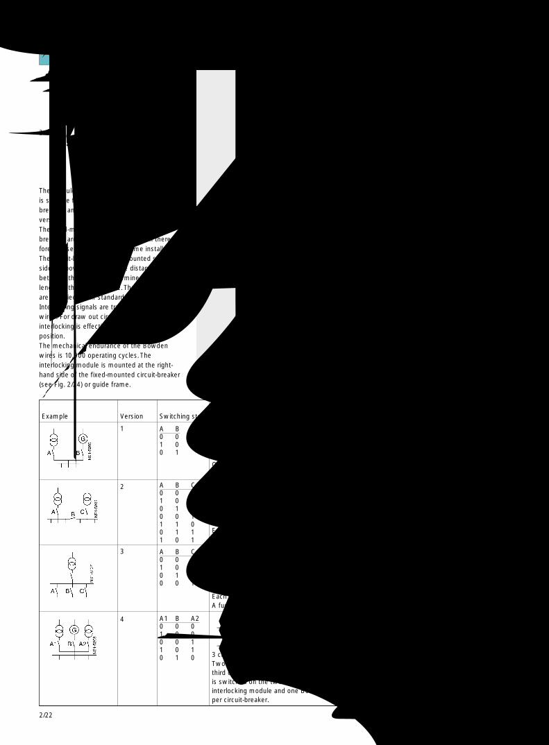
2/22
相互机械联锁 Mutual mechanical interlocking
相互机械联锁模块适用于两台或三台相互机械联锁的断路器。
固定式和抽屉式断路器可相互联锁,因而可安装于同一个系统中。
断路器可左右排列或上下排列; 断路器之间的距离取决于钢缆的长度。钢缆的标准长度为2m,可提供长于2m的钢缆。联缆信号由钢缆传送。对于抽屉式断路器,联锁只有在断路器处于运行位置时才有效。
钢缆的机械寿命为10,000次。联锁模块安装于固定式断路器或导向框架的右侧。
The module for mutual mechanical interlockingis suitable for two or -three 3WN6 circuit-breakers and can be easily adapted to eachversion.The fixed-mounted and draw-out circuit-breakers are fully compatible and can there-fore be used together in the same installation.The circuit-breakers can be mounted side-by-side or above each other; the distancebetween them is only determined by thelength of the Bowden wire. The Bowden wiresare supplied in 2m standard lengths.Interlocking signals are transferred via thewires. For draw out circuit-breakersinterlocking is effective only in the connectedposition.The mechanical endurance of the Bowdenwires is 10,000 operating cycles. Theinterlocking module is mounted at the right-hand side of the fixed-mounted circuit-breaker(see Fig. 2/24) or guide frame.
图 25 带联锁钢缆的联锁模块Fig. 2/25 Interlocking module with Bowden wire
图 24 3WN6 断路器,4 极,带联锁模块和联锁钢缆Fig. 2/24 3WN6 circuit-breaker,4-pole,with interlocking module and Bowden wire
例子 型式 开关状态 描述Example Version Switching state Description
1
2
3
4
两台断路器之间相互联锁一台断路器只有在另一台断路器分闸后才能合闸。每台断路器需带一联锁模块和一根联锁钢缆。2 circuit-breakers back to back:One circuit-breaker can only be switched on if the other is switched off.Each circuit breaker features an interlocking module and a Bowden wire
三台断路器之间相互联锁当一台断路器分闸时,可任意合闸另外两台断路器。每台断路器需带一联锁模块和两根联锁钢缆。3 stacked circuit-breakers:Any two circuit-breaker can be switched on when the third is locked.Each circuit breaker features an interlocking module and a Bowden wire.A furthe Bowden wire is additionally needed per circuit-breaker.
三台断路器之间相互联锁当一台断路器合闸后,另外两台断路器不能合闸。每台断路器需带一联锁模块和两根联锁钢缆。3 stacked circuit-breakers:If one circuit-breaker is switched on, the other two can not be closed.Each circuit breaker features an interlocking module and a Bowden wireA furthe Bowden wire is additionally needed per circuit-breaker.
三台断路器之间相互联锁两台断路器(A1,A2)可独立地分合闸,同时如果该两台断路器(A1,A2)分闸后,第三台(B)断路器才能合闸。如果该第三台断路器(B)合闸后,其他两台断路器(A1,A2)不能合闸。两台断路器(A1,A2)需带一联锁模块和两根联锁钢缆。3 circuit-breakers back to back:Two circuit-breakers can be switched on or off independently of each other, whereas thethird one can only be switched on if the others are switched off. If the third circuit-breakeris switched on the two others cannot be closed. The two circuit-breakers each feature oneinterlocking module and one Bowden wire. A further Bowden wire is additionally neededper circuit-breaker.
A B C0 0 01 0 00 1 00 0 11 1 00 1 11 0 1
A B C0 0 01 0 00 1 00 0 1
A1 B A20 0 01 0 00 0 11 0 10 1 0
A B0 01 00 1
3WN6断路器,至 3200A3WN6 Circuit-Breakers, up to 3200A
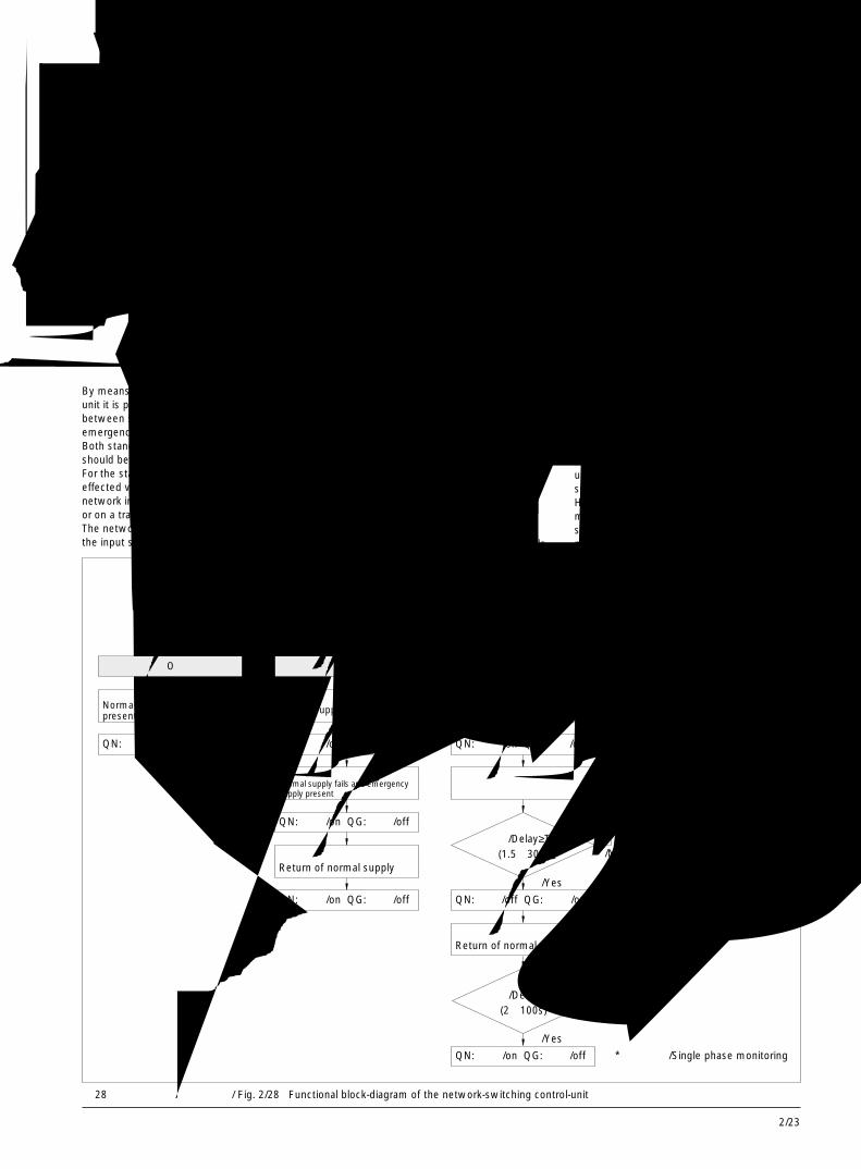
2/23
2
电源转换装置 Network-switching control unit
该电源切换装置 (3WX3 666-7JA00) 可用来在标准电网和后备应急电源之间实现自动转换。
标准电网和应急电源都应为 380/400V AC。电源转换装置平时监控两台断路器的进线
端。如果标准电网发生断电,转换装置会自动转
换至应急电源,使应急电网中的断路器自动合闸。当标准电网恢复供电时,转换装置会自动切换至标准电网。
与电源转换装置相连的两台断路器要求具有如下基本配置:3WN6⋯-⋯58-1kA..(空着的位置表示可任意选择相应的配置)
电源转换装置可墙面安装,也可安装于开关柜内。
借助于电源转换装置,可实现电源自动转换,符合 IEC947-6-1 标准。
两台 3WN6 断路器必须相互机械联锁(有关选型和订货数据,见第 2/54 页)。
By means of the network-switching controlunit it is possible to switch automaticallybetween standard network infeed andemergency network infeed.Both standard and emergency networksshould be 380/400 V AC.For the standard network, infeed is generallyeffected via a transformer. Emergencynetwork infeed may be based on a generatoror on a transformer.The network-switching control unit monitorsthe input side of both circuit-breakers. In case
图 26 电源切换装置Fig. 2/26 Network-switching control-unit
图 27Fig. 2/27
of failure of the standard network infeed, theunit switches automatically to the emergencynetwork. When the standard network infeed isrestored the control unit switchesautomatically switches back.Two circuit-breakers with the following basicconfiguration are required for the switching:3WN6...-...58-1kA.(empty positions can be selected freely).The network-switching control unit is suitable
for wall-mounting as well as for installationinside the cubicle.Inside the cubicle it can beinstalled also without housing.By means of the network-switching controlunit it is possible to realize automatic network-switchings according to IEC 947-6-1.Here the two 3WN6 circuit-breakers must bemutually interlocked mechanically. (Forselection and ordering data, see Accessories,page 2/54).
标准电网Normal supply 应急电源
Emergencysupply
电源切换装置Control unit
QN QG
图 28 电源转换装置功能示意图 / Fig. 2/28 Functional block-diagram of the network-switching control-unit
分断档 0 标准电网档Normal supply
标准电网或应急电源均正常Normal or emergency supplypresent
标准电网供电Normal supply present
自动档 /AUTOMATIC 应急电源档 /Emergency supply
应急电源供电Emergency supply present
QN: 分闸 /off QG: 分闸 /off QN: 合闸 /on QG: 分闸 /off
标准电网断电,应急电源正常Normal supply fails and emergencysupply present
标准电网或其某一相断电*,应急电源正常
标准电网恢复供电Return of normal supply
标准电网恢复供电Return of normal supply
应急电源断电Emergency supply fails
延时 /Delay≥T1?(1.5~30s)
是 /Yes
标准电网恢复供电Return of normal supply
延时 /Delay≥T2?(2~100s)
否 /No
是 /Yes
否 /No
* 单相监控 /Single phase monitoring
标准电网供电Normal supply present
QN: 合闸 /on QG: 分闸 /off QN: 分闸 /off QG: 合闸 /on
QN: 合闸 /on QG: 分闸 /off
QN: 合闸 /on QG: 分闸 /off QN: 分闸 /off QG: 合闸 /on QN: 分闸 /off QG: 合闸 /on
QN: 分闸 /off QG: 合闸 /on
QN: 合闸 /on QG: 分闸 /off
3WN6断路器,至 3200A3WN6 Circuit-Breakers, up to 3200A

2/24
尺寸等级 / 尺寸等级 额定电流In 脱扣电流Ir
额定电流 In 的设定范围
I 630A 126-315A 0 A160-400A 0 B200-500A 0 C252-630A 0 D
800A 320-800A 1 E1000A 400-1000A 2 F1250A 500-1250A 3 G1600A 640-1600A 4 H
II 2000A 252-630A2) 5 D500-1250A2) 5 G640-1600A2) 5 H800-2000A 5 J
2500A 1000-2500A 6 K3200A 1280-3200A 7 M
安装方式 主回路连接说明见第 2/7 页固定式 主回路连接母排水平后置(标准型) 6
主回路连接母排前置,单孔,顶部和底部 3
主回路连接母排前置,双孔,顶部和底部 2(孔洞按照 DIN43673 标准)
抽屉式 抽屉式断路器本体,不带导向框架 7对其他型式 抽屉式断路器,带导向框架 8的导向框架 标准型:主回路连接母排水平后置,带导轨见第 2/9 页
过电流脱扣器 V 型“zn” 0 V(功能介绍见 B 型“azn” 0 B第 2/10 页) C 型“aznNg”1) 0 C
D 型“aznN”1)
基本功能,带液晶显示 1 D基本功能和附加功能 1,带液晶显示 3 D基本功能和附加功能 2,带液晶显示 7 DE 型“aznNg”1)
基本功能,带液晶显示 1 E基本功能和附加功能 1,带液晶显示 3 E基本功能和附加功能 2,带液晶显示 7 EH 型“aznN”1)
基本功能 1 H基本功能和附加功能 1 3 H基本功能和附加功能 2 7 HJ 型“aznNg”1)
基本功能 1 J基本功能和附加功能 1 3 J基本功能和附加功能 2 7 JN 型“aznN”1)
基本功能 1 N基本功能和附加功能 1 3 N基本功能和附加功能 2 7 NP 型“aznNg”1)
基本功能 1 P基本功能和附加功能 1 3 P基本功能和附加功能 2 7 P
3WN6断路器,3极,至 3200A3WN6 Circuit-Breakers, 3-pole, up to 3200A
3WN 6 □ □ 1 -□ □ □ □ □ - □ □ □ □
3WN 6 □ □ 1 -□ □ □ □ □ - □ □ □ □
选型及订货数据 Selection and ordering data类型 订货号的补充 订货号额定工作电压Ue 至AC 690V
■ 断路器还可具有额定短时耐受电流Icw=50 kA/1s,见第 2/63 页
1) 用于对 N 导体进行过载保护和用于接地故障保护的电流互感器必须另外订货,见第 2/46 页。
2) 不适用于 N 型或 P 型过电流脱扣器。 订货号第 11-第 16个位置的说明,见第 2/26 页
1 2 3 4 5 6 7 8 9 10 11 12 13 14 15 16

2/25
2
3WN 6 □ □ 1 -□ □ □ □ □ - □ □ □ □
选型及订货数据 Selection and ordering dataVersion Order No. Order No.Rated operational voltage supplementUe up to AC 690V 3WN 6 □ □ 1 -□ □ □ □ □ - □ □ □ □
Size/Rated Size Rated Setting range of thecurrent In current In tripping current Ir
I 630A 126-315A 0 A160-400A 0 B200-500A 0 C252-630A 0 D
800A 320-800A 1 E1000A 400-1000A 2 F1250A 500-1250A 3 G1600A 640-1600A 4 H
II 2000A 252-630A2) 5 D500-1250A2) 5 G640-1600A2) 5 H800-2000A 5 J
2500A 1000-2500A 6 K3200A 1280-3200A 7 M
Mounting Main connections see page 2/7version Main connections at the rear, horizontal (standard) 6Fixed mounted Main connections accessible from the front, 3version single hole top and bottom
Main connections accessible from the front, 2double hole top and bottom, according to DIN 43 673
Draw-out Draw-out circuit-breaker without guide frame 7version Draw-out circuit-breaker with guide frame 8Other Standard type:main connections at the rear,versions of horizontal with guide railsthe guide-frame seepaga 2/9.
Overcurrent Version V “zn” 0 Vrelease Version B “azn” 0 B(seefunction Version C “aznNg” 1) 0 Coverview Version D “aznN” 1)
page 2/10) Basic functions with LCD-display 1 DBasic functions and additional functions 1 with LCD-display 3 DBasic functions and additional functions 2 with LCD-display 7 DVersion E “aznNg” 1)
Basic functions with LCD-display 1 EBasic functions and additional functions 1 with LCD-display 3 EBasic functions and additional functions 2 with LCD-display 7 EVersion H “aznN” 1)
Basic functions 1 HBasic functions and additional functions 1 3 HBasic functions and additional functions 2 7 HVersion J “aznNg” 1)
Basic functions 1 JBasic functions and additional functions 1 3 JBasic functions and additional functions 2 7 JVersion N “aznN” 1)
Basic functions 1 NBasic functions and additional functions 1 3 NBasic functions and additional functions 2 7 NVersion P “aznNg” 1)
Basic functions 1 PBasic functions and additional functions 1 3 PBasic functions and additional functions 2 7 P
■ Circuit-breakers also available with rated short-timewithstand current Icw=50 kA/1s see page 2/63
1) Transfomer for overload protection in neutral conductor and transformer forearth fault must be ordered separately, see page 2/46.
2) Not possible with over-current release version N or P.
1 2 3 4 5 6 7 8 9 10 11 12 13 14 15 16
positons 11 to 16 of theorder No see page 2/27.
3WN6断路器,3极,至 3200A3WN6 Circuit-Breakers, 3-pole, up to 3200A
2/26
3WN 6 □ □ 1 -□ □ □ □ □ - □ □ □ □
1 2 3 4 5 6 7 8 9 10 11 12 13 14 15 16
类型 订货号的补充 订货号
3WN 6 □ □ 1 -□ □ □ □ □ - □ □ □ □
选型及订货数据 Selection and ordering data
操作机构 手动储能,机械合闸 0 5
手动储能,机械和电气合闸
电气合闸线圈AC 50/60Hz V DC V- 24 1 1- 48 1 4- 60 1 5
110-127 110-125 1 6220-240 220-250 1 8
手动/电动机储能,机械和电气合闸电动机 电气合闸线圈AC 50/60Hz V DC V AC 50/60Hz V DC V- 24 - 24 5 1- 48 - 48 5 4- 60 - 60 5 5
110-127 110-125 - 24 7 1110-127 110-125 - 48 7 4110-127 110-125 - 60 7 5110-127 110-125 110-127 110-125 5 6110-127 110-125 220-240 220-250 7 8
220-240 220-250 - 24 8 1220-240 220-250 - 48 8 4220-240 220-250 - 60 8 5220-240 220-250 110-127 110-125 8 6220-240 220-250 220-240 220-250 5 8
第 1 辅助脱扣器 不带第 1 辅助脱扣器 0 A分励脱扣器“f”, F1AC 50/60Hz V DC V- 24 1 B- 30 1 E- 48 1 F- 60 1 G
110-127 110-125 1 H220-240 220-250 1 K欠电压脱扣器“r”,F3(无延时 0 ms,短延时可调为 100ms)AC 50/60Hz V DC V- 24 3 B- 30 3 E- 48 3 F- 60 3 G
110-127 110-125 3 H220-240 220-250 3 K380-415 - 3 M欠电压脱扣器“rc”, F8 (从 0.2~3.2s延时可调)AC 50/60Hz V DC V110-127 - 4 H220-240 - 4 K380-415 - 4 M
第 2 辅助脱扣器 不带第 2 辅助脱扣器 A分励脱扣器“f”,F2AC 50/60Hz V DC V- 24 B- 30 E- 48 F- 60 G
110-127 110-125 H220-240 220-250 K
辅助触头 第 1 个辅助触头块 1
2NO + 2NC第 1 个 + 第 2 个辅助触头块 32NO+2NC+2CO
订货号第 5~ 第 10 个位置的说明见第 2/24 页
3WN6断路器,3极,至 3200A3WN6 Circuit-Breakers, 3-pole, up to 3200A

2/27
2
3WN 6 □ □ 1 -□ □ □ □ □ - □ □ □ □
1 2 3 4 5 6 7 8 9 10 11 12 13 14 15 16
Version Order No. Order No.supplement
3WN 6 □ □ 1 -□ □ □ □ □ - □ □ □ □
选型及订货数据 Selection and ordering data
Operating Manual operating mechanism with stored-energy 0 5mechanism feature with mechanical closing
Manual operating mechahism with stored-energyfeature with mechanical and electrical closing
Closing solenoidAC 50/60Hz V DC V- 24 1 1- 48 1 4- 60 1 5
110-127 110-125 1 6220-240 220-250 1 8
Manual/motorized mechanism with stored-energywith mechanical and electrical closing
Motor ClosingAC 50/60Hz V DC V AC 50/60Hz V DC V- 24 - 24 5 1- 48 - 48 5 4- 60 - 60 5 5
110-127 110-125 - 24 7 1110-127 110-125 - 48 7 4110-127 110-125 - 60 7 5110-127 110-125 110-127 110-125 5 6110-127 110-125 220-240 220-250 7 8
220-240 220-250 - 24 8 1220-240 220-250 - 48 8 4220-240 220-250 - 60 8 5220-240 220-250 110-127 110-125 8 6220-240 220-250 220-240 220-250 5 8
1st auxiliary without 1st. auxiliary release 0 Arelease Shunt release “f”. F1
AC 50/60Hz V DC V- 24 1 B- 30 1 E- 48 1 F- 60 1 G
110-127 110-125 1 H220-240 220-250 1 K
Undervoltage release "r", F3(undelayed 0 ms, adjustable for short delay 100 ms)AC 50/60Hz V DC V- 24 3 B- 30 3 E- 48 3 F- 60 3 G
110-127 110-125 3 H220-240 220-250 3 K380-415 - 3 M
Undervoltage release "rc", F8(delay adjustable from 0.2 to 3.2 s)AC 50/60Hz V DC V110-127 - 4 H220-240 - 4 K380-415 - 4 M
2nd auxiliary without 2nd auxiliary release Arelease Shunt release "r", F2
AC 50/60Hz V DC V- 24 B- 30 E- 48 F- 60 G
110-127 110-125 H220-240 220-250 K
Auxiliary 1st auxiliary contact block 1contacts 2NO + 2NC
1st+2nd auxiliary contact block 32NO+2NC+2CO
position 5 to 10 of the order No. see page 2/25.
3WN6断路器,3极,至 3200A3WN6 Circuit-Breakers, 3-pole, up to 3200A
2/28
尺寸等级 / 尺寸等级 额定电流In 脱扣电流Ir
额定电流 In 的设定范围
I 630A 126-315A 0 A160-400A 0 B200-500A 0 C252-630A 0 D
800A 320-800A 1 E1000A 400-1000A 2 F1250A 500-1250A 3 G1600A 640-1600A 4 H
II 2000A 252-630A1) 5 D500-1250A1) 5 G640-1600A1) 5 H800-2000A 5 J
2500A 1000-2500A 6 K3200A 1280-3200A 7 M
安装方式 主回路连接说明见第 2/7 页固定式 主回路连接母排水平后置(标准型) 6
主回路连接母排前置,单孔,顶部和底部 3
主回路连接母排前置,双孔,顶部和底部 2(孔洞按照 DIN43673 标准)
抽屉式 抽屉式断路器本体,不带导向框架 7对其他型式 抽屉式断路器,带导向框架 8的导向框架 标准型:主回路连接母排水平后置,带导轨见第 2/9 页
过电流脱扣器 V 型“zn” 0 V(功能介绍见 B 型“azn” 0 B第 2/10 页) G 型“aznNg”2) 0 G
D 型“aznN”2)
基本功能,带液晶显示 1 D基本功能和附加功能 1,带液晶显示 3 D基本功能和附加功能 2,带液晶显示 7 DE 型“aznNg”3)
基本功能,带液晶显示 1 E基本功能和附加功能 1,带液晶显示 3 E基本功能和附加功能 2,带液晶显示 7 EF 型“aznNg”2)
基本功能,带液晶显示 1 F基本功能和附加功能 1,带液晶显示 3 F基本功能和附加功能 2,带液晶显示 7 FH 型“aznN”2)
基本功能 1 H基本功能和附加功能 1 3 H基本功能和附加功能 2 7 HJ 型“aznNg”3)
基本功能 1 J基本功能和附加功能 1 3 J基本功能和附加功能 2 3 JK 型“aznNg”2)
基本功能 1 K基本功能和附加功能 1 3 K基本功能和附加功能 2 3 KN 型“aznN”2)
基本功能 1 N基本功能和附加功能 1 3 N基本功能和附加功能 2 7 NP 型“aznNg”2)4)
基本功能 1 P基本功能和附加功能 1 3 P基本功能和附加功能 2 7 P
3WN 6 □ □ 3 -□ □ □ □ □ - □ □ □ □
3WN 6 □ □ 3 -□ □ □ □ □ - □ □ □ □
选型及订货数据 Selection and ordering data类型 订货号的补充 订货号额定工作电压Ue 至AC 690V
■ 断路器还可具有额定短时耐受电流Icw=50 kA/1s,见第 2/63 页1) 不适用于 N 型或 P 型过电流脱扣器。2) 用于 N 导体的第 4 个电流互感器已安装在断路器内。3) 用于对 N 导体进行过载保护和用于接地故障保护的电流互感器必须另外订货,见第 2/46 页4) 用于变压器星形接地点的电流互感器必须另外订货,见第 2/46 页。
订货号第11~第16个位置的说明,见第 2/30 页
1 2 3 4 5 6 7 8 9 10 11 12 13 14 15 16
3WN6断路器,4极,至 3200A3WN6 Circuit-Breakers, 4-pole, up to 3200A
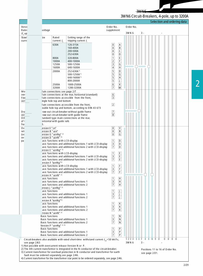
2/29
2
1 2 3 4 5 6 7 8 9 10 11 12 13 14 15 16
Size/Rated Size Rated Setting range of thecurrent In current In tripping current Ir
I 630A 126-315A 0 A160-400A 0 B200-500A 0 C252-630A 0 D
800A 320-800A 1 E1000A 400-1000A 2 F1250A 500-1250A 3 G1600A 640-1600A 4 H
II 2000A 252-630A1) 5 D500-1250A1) 5 G640-1600A1) 5 H800-2000A 5 J
2500A 1000-2500A 6 K3200A 1280-3200A 7 M
Mounting Main connections see page 2/7version Main connections at the rear, horizontal (standard) 6Fixed mounted Main connections accessible from the front, 3version single hole top and bottom
Main connections accessible from the front, 2double hole top and bottom, according to DIN 43 673
Draw-out Draw-out circuit-breaker without guide frame 7version Draw-out circuit-breaker with guide frame 8Other versions Standard type main connections at the rear,of the guide horizontal with guide railsframe see paga 2/9.
Overcurrent Version V “zn” 0 Vrelease Version B “azn” 0 B(see function Version G “aznNg” 2) 0 Goverview Version D “aznN” 2)
page 2/10) Basic functions with LCD-display 1 DBasic functions and additional functions 1 with LCD-display 3 DBasic functions and additional functions 2 with LCD-display 7 DVersion E “aznNg” 3)
Basic functions with LCD-display 1 EBasic functions and additional functions 1 with LCD-display 3 EBasic functions and additional functions 2 with LCD-display 7 EVersion F "aznNg" 2)
Basic functions with LCD-display 1 FBasic functions and additional functions 1 with LCD-display 3 FBasic functions and additional functions 2 with LCD-display 7 FVersion H “aznN” 2)
Basic functions 1 HBasic functions and additional functions 1 3 HBasic functions and additional functions 2 7 Hversion J “aznNg” 3)
Basic functions 1 JBasic functions and additional functions 1 3 JBasic functions and additional functions 2 7 JVersion K "aznNg" 2)
Basic functions 1 KBasic functions and additional functions 1 3 KBasic functions and additional functions 2 7 KVersion N “aznN” 2)
Basic functions 1 NBasic functions and additional functions 1 3 NBasic functions and additional functions 2 7 NVersion P “aznNg” 2) 4)
Basic functions 1 PBasic functions and additional functions 1 3 PBasic functions and additional functions 2 7 P
3WN 6 □ □ 3 -□ □ □ □ □ - □ □ □ □
选型及订货数据 Selection and ordering dataVersion Order No. Order No.Rated operational voltage supplementUe up to AC 690V 3WN 6 □ □ 3 -□ □ □ □ □ - □ □ □ □
■ Circuit-breakers also available with rated short-time withstand current Icw=50 kA/1s, see page 2/631) Not possible with overcurrent release Version N or P.2) The 4th current transformer is integrated in the N conductor of the circuit-breaker.3) Current transformer for overload protection in N conductor and transformer for earth
fault must be ordered separately,see page 2/46.4) Current transformer for the transformer star point to be ordered separately, see page 2/46.
Positions 11 to 16 of Order No.see page 2/31.
3WN6断路器,4极,至 3200A3WN6 Circuit-Breakers, 4-pole, up to 3200A
2/30
3WN6断路器,4极,至 3200A3WN6 Circuit-Breakers, 4-pole, up to 3200A
3WN 6 □ □ 3 -□ □ □ □ □ - □ □ □ □
1 2 3 4 5 6 7 8 9 10 11 12 13 14 15 16
类型 订货号的补充 订货号
3WN 6 □ □ 3 -□ □ □ □ □ - □ □ □ □
选型及订货数据 Selection and ordering data
操作机构 手动储能,机械合闸 0 5
手动储能,机械和电气合闸
电气合闸线圈AC 50/60Hz V DC V- 24 1 1- 48 1 4- 60 1 5
110-127 110-125 1 6220-240 220-250 1 8
手动/电动机储能,机械和电气合闸电动机 电气合闸线圈AC 50/60Hz V DC V AC 50/60Hz V DC V- 24 - 24 5 1- 48 - 48 5 4- 60 - 60 5 5
110-127 110-125 - 24 7 1110-127 110-125 - 48 7 4110-127 110-125 - 60 7 5110-127 110-125 110-127 110-125 5 6110-127 110-125 220-240 220-250 7 8
220-240 220-250 - 24 8 1220-240 220-250 - 48 8 4220-240 220-250 - 60 8 5220-240 220-250 110-127 110-125 8 6220-240 220-250 220-240 220-250 5 8
第 1 辅助脱扣器 不带第 1 辅助脱扣器 0 A分励脱扣器“f”, F1AC 50/60Hz V DC V- 24 1 B- 30 1 E- 48 1 F- 60 1 G
110-127 110-125 1 H220-240 220-250 1 K欠电压脱扣器“r”,F3(无延时 0 ms,短延时可调为 100ms)AC 50/60Hz V DC V- 24 3 B- 30 3 E- 48 3 F- 60 3 G
110-127 110-125 3 H220-240 220-250 3 K380-415 - 3 M欠电压脱扣器“rc”, F8 (从 0.2~3.2s延时可调)AC 50/60Hz V DC V110-127 - 4 H220-240 - 4 K380-415 - 4 M
第 2 辅助脱扣器 不带第 2 辅助脱扣器 A分励脱扣器“f”,F2AC 50/60Hz V DC V- 24 B- 30 E- 48 F- 60 G
110-127 110-125 H220-240 220-250 K
辅助触头 第 1 个辅助触头块 1
2NO + 2NC第 1 个 + 第 2 个辅助触头块 32NO+2NC+2CO
订货号第 5~ 第 10 个位置的说明见第 2/28 页
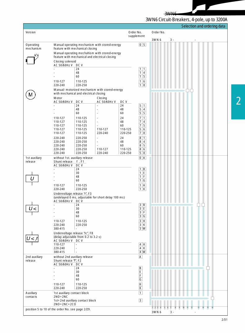
2/31
2
3WN 6 □ □ 3 -□ □ □ □ □ - □ □ □ □
1 2 3 4 5 6 7 8 9 10 11 12 13 14 15 16
Version Order No. Order No.supplement
3WN 6 □ □ 3 -□ □ □ □ □ - □ □ □ □
选型及订货数据 Selection and ordering data
Operating Manual operating mechanism with stored-energy 0 5mechanism feature with mechanical closing
Manual operating mechahism with stored-energyfeature with mechanical and electrical closing
Closing solenoidAC 50/60Hz V DC V- 24 1 1- 48 1 4- 60 1 5
110-127 110-125 1 6220-240 220-250 1 8
Manual/motorized mechanism with stored-energywith mechanical and electrical closing
Motor ClosingAC 50/60Hz V DC V AC 50/60Hz V DC V- 24 - 24 5 1- 48 - 48 5 4- 60 - 60 5 5
110-127 110-125 - 24 7 1110-127 110-125 - 48 7 4110-127 110-125 - 60 7 5110-127 110-125 110-127 110-125 5 6110-127 110-125 220-240 220-250 7 8
220-240 220-250 - 24 8 1220-240 220-250 - 48 8 4220-240 220-250 - 60 8 5220-240 220-250 110-127 110-125 8 6220-240 220-250 220-240 220-250 5 8
1st auxiliary without 1st. auxiliary release 0 Arelease Shunt release “f”. F1
AC 50/60Hz V DC V- 24 1 B- 30 1 E- 48 1 F- 60 1 G
110-127 110-125 1 H220-240 220-250 1 K
Undervoltage release "r", F3(undelayed 0 ms, adjustable for short delay 100 ms)AC 50/60Hz V DC V- 24 3 B- 30 3 E- 48 3 F- 60 3 G
110-127 110-125 3 H220-240 220-250 3 K380-415 - 3 M
Undervoltage release "rc", F8(delay adjustable from 0.2 to 3.2 s)AC 50/60Hz V DC V110-127 - 4 H220-240 - 4 K380-415 - 4 M
2nd auxiliary without 2nd auxiliary release Arelease Shunt release "f", F2
AC 50/60Hz V DC V- 24 B- 30 E- 48 F- 60 G
110-127 110-125 H220-240 220-250 K
Auxiliary 1st auxiliary contact block 1contacts 2NO+2NC
1st+2nd auxiliary contact block 32NO+2NC+2CO
position 5 to 10 of the order No. see page 2/29.
3WN6断路器,4极,至 3200A3WN6 Circuit-Breakers, 4-pole, up to 3200A

2/32
选型及订货数据 Selection and ordering data
尺寸等级 / 尺寸等级 额定电流In
额定电流 In
I 630A 0800A 11000A 2
1250A 31600A 4
II 2000A 52500A 63200A 7
安装方式 主回路连接说明见第 2/7 页固定式 主回路连接母排水平后置(标准型) 6
主回路连接母排前置,单孔,顶部和底部 3
主回路连接母排前置,双孔,顶部和底部 2(孔洞按照 DIN43673 标准)
抽屉式 抽屉式断路器本体,不带导向框架 7其他型式 抽屉式断路器本体,带导向框架 8的导向框架 标准型:主回路连接母排水平后置,带导轨见第 2/9 页
3WN 6 □ □ 1 - 0 W A □ □ - □ □ □ □
类型 订货号的补充 订货号额定工作电压Ue 至AC 690V不带电子式过电流脱扣器系统
■ 断路器还可具有额定短时耐受电流Icw=50kA/1s,见第 2/63 页
订货号第11~第16个位置的说明,见第 2/34 页
1 2 3 4 5 6 7 8 9 10 11 12 13 14 15 16
3WN 6 □ □ 1 - 0 W A □ □ - □ □ □ □
3WN6负荷隔离开关,3极,至 3200A3WN6 Non-Automatic Circuit-Breakers, 3-pole, up to 3200A
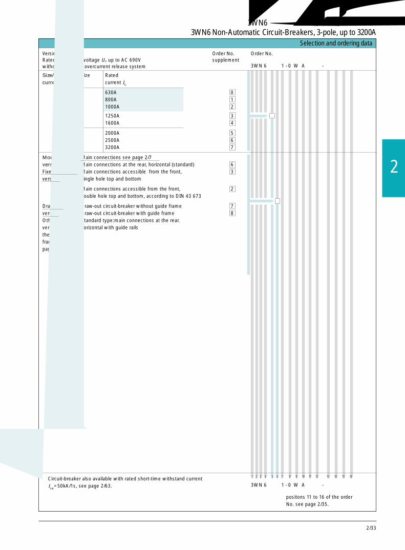
2/33
2
3WN6负荷隔离开关,3极,至 3200A3WN6 Non-Automatic Circuit-Breakers, 3-pole, up to 3200A
选型及订货数据 Selection and ordering data
Size/Rated Size Ratedcurrent In current In
I 630A 0800A 11000A 2
1250A 31600A 4
II 2000A 52500A 63200A 7
Mounting Main connections see page 2/7version Main connections at the rear, horizontal (standard) 6Fixed mounted Main connections accessible from the front, 3version single hole top and bottom
Main connections accessible from the front, 2double hole top and bottom, according to DIN 43 673
Draw-out Draw-out circuit-breaker without guide frame 7version Draw-out circuit-breaker with guide frame 8Other Standard type:main connections at the rear.versions of horizontal with guide railsthe guide-frame seepaga 2/9.
positons 11 to 16 of the orderNo. see page 2/35.
1 2 3 4 5 6 7 8 9 10 11 12 13 14 15 16
Version Order No. Order No.Rated operational voltage Ue up to AC 690V supplementwithout electronic overcurrent release system
■ Circuit-breaker also available with rated short-time withstand currentIcw=50kA/1s, see page 2/63. 3WN 6 □ □ 1 - 0 W A □ □ - □ □ □ □
3WN 6 □ □ 1 - 0 W A □ □ - □ □ □ □
2/34
3WN6负荷隔离开关,3极,至 3200A3WN6 Non-Automatic Circuit-Breakers, 3-pole, up to 3200A
1 2 3 4 5 6 7 8 9 10 11 12 13 14 15 16
类型 订货号的补充 订货号
选型及订货数据 Selection and ordering data
操作机构 手动储能,机械合闸 0 5
手动储能,机械和电气合闸
电气合闸线圈AC 50/60Hz V DC V- 24 1 1- 48 1 4- 60 1 5
110-127 110-125 1 6220-240 220-250 1 8
手动/电动机储能,机械和电气合闸电动机 电气合闸线圈AC 50/60Hz V DC V AC 50/60Hz V DC V- 24 - 24 5 1- 48 - 48 5 4- 60 - 60 5 5
110-127 110-125 - 24 7 1110-127 110-125 - 48 7 4110-127 110-125 - 60 7 5110-127 110-125 110-127 110-125 5 6110-127 110-125 220-240 220-250 7 8
220-240 220-250 - 24 8 1220-240 220-250 - 48 8 4220-240 220-250 - 60 8 5220-240 220-250 110-127 110-125 8 6220-240 220-250 220-240 220-250 5 8
第 1 辅助脱扣器 不带第 1 辅助脱扣器 0 A分励脱扣器“f”, F1AC 50/60Hz V DC V- 24 1 B- 30 1 E- 48 1 F- 60 1 G
110-127 110-125 1 H220-240 220-250 1 K欠电压脱扣器“r”,F3(无延时 0 ms,短延时可调为 100ms)AC 50/60Hz V DC V- 24 3 B- 30 3 E- 48 3 F- 60 3 G110-127 110-125 3 H220-240 220-250 3 K380-415 - 3 M欠电压脱扣器“rc”, F8 (从 0.2~3.2s延时可调)AC 50/60Hz V DC V110-127 - 4 H220-240 - 4 K380-415 - 4 M
第 2 辅助脱扣器 不带第 2 辅助脱扣器 A分励脱扣器“f”,F2AC 50/60Hz V DC V- 24 B- 30 E- 48 F- 60 G
110-127 110-125 H220-240 220-250 K
辅助触头 第 1 个辅助触头块 12NO + 2NC
第 1 个 + 第 2 个辅助触头块 32NO + 2NC + 2CO
订货号第 5~ 第 6 个位置的说明见第 2/32 页
不带电子式过电流脱扣器系统
3WN 6 □ □ 1 - 0 W A □ □ - □ □ □ □
3WN 6 □ □ 1 - 0 W A □ □ - □ □ □ □
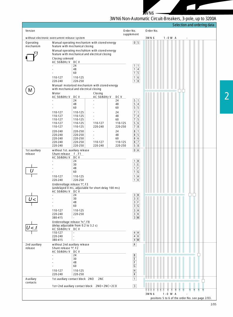
2/35
2
1 2 3 4 5 6 7 8 9 10 11 12 13 14 15 16
Version Order No. Order No.supplement
选型及订货数据 Selection and ordering data
Operating Manual operating mechanism with stored-energy 0 5mechanism feature with mechanical closing
Manual operating mechahism with stored-energyfeature with mechanical and electrical closing
Closing solenoidAC 50/60Hz V DC V- 24 1 1- 48 1 4- 60 1 5
110-127 110-125 1 6220-240 220-250 1 8
Manual/motorized mechanism with stored-energywith mechanical and electrical closing
Motor ClosingAC 50/60Hz V DC V AC 50/60Hz V DC V- 24 - 24 5 1- 48 - 48 5 4- 60 - 60 5 5
110-127 110-125 - 24 7 1110-127 110-125 - 48 7 4110-127 110-125 - 60 7 5110-127 110-125 110-127 110-125 5 6110-127 110-125 220-240 220-250 7 8
220-240 220-250 - 24 8 1220-240 220-250 - 48 8 5220-240 220-250 - 60 8 6220-240 220-250 110-127 110-125 8 7220-240 220-250 220-240 220-250 5 8
1st auxiliary without 1st. auxiliary release 0 Arelease Shunt release “f”. F1
AC 50/60Hz V DC V- 24 1 B- 30 1 E- 48 1 F- 60 1 G
110-127 110-125 1 H220-240 220-250 1 K
Undervoltage release "r", F3(undelayed 0 ms, adjustable for short delay 100 ms)AC 50/60Hz V DC V- 24 3 B- 30 3 E- 48 3 F- 60 3 G
110-127 110-125 3 H220-240 220-250 3 K380-415 - 3 M
Undervoltage release "rc", F8(delay adjustable from 0.2 to 3.2 s)AC 50/60Hz V DC V110-127 - 4 H220-240 - 4 K380-415 - 4 M
2nd auxiliary without 2nd auxiliary release Arelease Shunt release "r", F2
AC 50/60Hz V DC V- 24 B- 30 E- 48 F- 60 G
110-127 110-125 H220-240 220-250 K
Auxiliary 1st auxiliary contact block 2NO+ 2NC 1contacts
1st+2nd auxiliary contact block 2NO+2NC+2CO 3
positons 5 to 6 of the order No. see page 2/33.
without electronic overcurrent release system
3WN 6 □ □ 1 - 0 W A □ □ - □ □ □ □
3WN 6 □ □ 1 - 0 W A □ □ - □ □ □ □
3WN6负荷隔离开关,3极,至 3200A3WN6 Non-Automatic Circuit-Breakers, 3-pole, up to 3200A

2/36
选型及订货数据 Selection and ordering data
尺寸等级 / 尺寸等级 额定电流In
额定电流 In
I 630A 0800A 11000A 2
1250A 31600A 4
II 2000A 52500A 63200A 7
安装方式 主回路连接说明见第 2/7 页固定式 主回路连接母排水平后置(标准型) 6
主回路连接母排前置,单孔,顶部和底部 3
主回路连接母排前置,双孔,顶部和底部 2(孔洞按照 DIN43673 标准)
抽屉式 抽屉式断路器本体,不带导向框架 7其他型式 抽屉式断路器,带导向框架 8的导向框架 标准型:主回路连接母排水平后置,带导轨见第 2/9 页
类型 订货号的补充 订货号额定工作电压Ue 至AC 690V不带电子式过电流脱扣器系统
■ 断路器还可具有额定短时耐受电流Icw=50kA/1s,见第 2/63 页
订货号第11~第16个位置的说明,见第 2/38 页
1 2 3 4 5 6 7 8 9 10 11 12 13 14 15 16
3WN 6 □ □ 3 - 0 W A □ □ - □ □ □ □
3WN 6 □ □ 3 - 0 W A □ □ - □ □ □ □
3WN6负荷隔离开关,4极,至 3200A3WN6 Non-Automatic Circuit-Breakers, 4-pole, up to 3200A
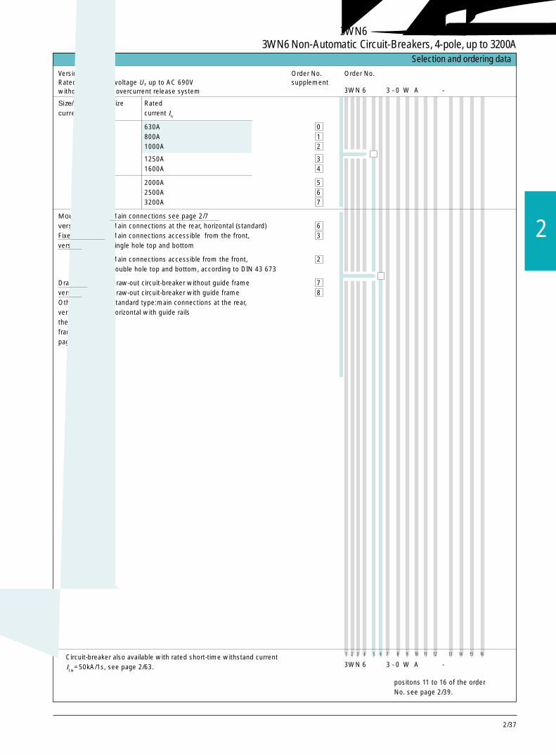
2/37
2
选型及订货数据 Selection and ordering data
Size/Rated Size Ratedcurrent In current In
I 630A 0800A 11000A 2
1250A 31600A 4
II 2000A 52500A 63200A 7
Mounting Main connections see page 2/7version Main connections at the rear, horizontal (standard) 6Fixed mounted Main connections accessible from the front, 3version single hole top and bottom
Main connections accessible from the front, 2double hole top and bottom, according to DIN 43 673
Draw-out Draw-out circuit-breaker without guide frame 7version Draw-out circuit-breaker with guide frame 8Other Standard type:main connections at the rear,versions of horizontal with guide railsthe guide-frame seepaga 2/9.
positons 11 to 16 of the orderNo. see page 2/39.
1 2 3 4 5 6 7 8 9 10 11 12 13 14 15 16
Version Order No. Order No.Rated operational voltage Ue up to AC 690V supplementwithout electronic overcurrent release system
■ Circuit-breaker also available with rated short-time withstand currentIcw=50kA/1s, see page 2/63. 3WN 6 □ □ 3 - 0 W A □ □ - □ □ □ □
3WN 6 □ □ 3 - 0 W A □ □ - □ □ □ □
3WN6负荷隔离开关,4极,至 3200A3WN6 Non-Automatic Circuit-Breakers, 4-pole, up to 3200A
2/38
1 2 3 4 5 6 7 8 9 10 11 12 13 14 15 16
类型 订货号的补充 订货号
选型及订货数据 Selection and ordering data
操作机构 手动储能,机械合闸 0 5
手动储能,机械和电气合闸
电气合闸线圈AC 50/60Hz V DC V- 24 1 1- 48 1 4- 60 1 5
110-127 110-125 1 6220-240 220-250 1 8
手动/电动机储能,机械和电气合闸电动机 电气合闸线圈AC 50/60Hz V DC V AC 50/60Hz V DC V- 24 - 24 5 1- 48 - 48 5 4- 60 - 60 5 5
110-127 110-125 - 24 7 1110-127 110-125 - 48 7 4110-127 110-125 - 60 7 5110-127 110-125 110-127 110-125 5 6110-127 110-125 220-240 220-250 7 8
220-240 220-250 - 24 8 1220-240 220-250 - 48 8 4220-240 220-250 - 60 8 5220-240 220-250 110-127 110-125 8 6220-240 220-250 220-240 220-250 5 8
第 1 辅助脱扣器 不带第 1 辅助脱扣器 0 A分励脱扣器“f”, F1AC 50/60Hz V DC V- 24 1 B- 30 1 E- 48 1 F- 60 1 G
110-127 110-125 1 H220-240 220-250 1 K欠电压脱扣器“r”,F3(无延时 0 ms,短延时可调为 100ms)AC 50/60Hz V DC V- 24 3 B- 30 3 E- 48 3 F- 60 3 G
110-127 110-125 3 H220-240 220-250 3 K380-415 - 3 M欠电压脱扣器“rc”, F8 (从 0.2~3.2s延时可调)AC 50/60Hz V DC V110-127 - 4 H220-240 - 4 K380-415 - 4 M
第 2 辅助脱扣器 不带第 2 辅助脱扣器 A分励脱扣器“f”,F2AC 50/60Hz V DC V- 24 B- 30 E- 48 F- 60 G
110-127 110-125 H220-240 220-250 K
辅助触头 第 1 个辅助触头块 1
2NO + 2NC第 1 个 + 第 2 个辅助触头块 32NO+2NC+2CO
订货号第 5 和第 6 个位置的说明见第 2/36 页
不带电子式过电流脱扣器系统
3WN 6 □ □ 3 - 0 W A □ □ - □ □ □ □
3WN 6 □ □ 3 - 0 W A □ □ - □ □ □ □
3WN6负荷隔离开关,4极,至 3200A3WN6 Non-Automatic Circuit-Breakers, 4-pole, up to 3200A
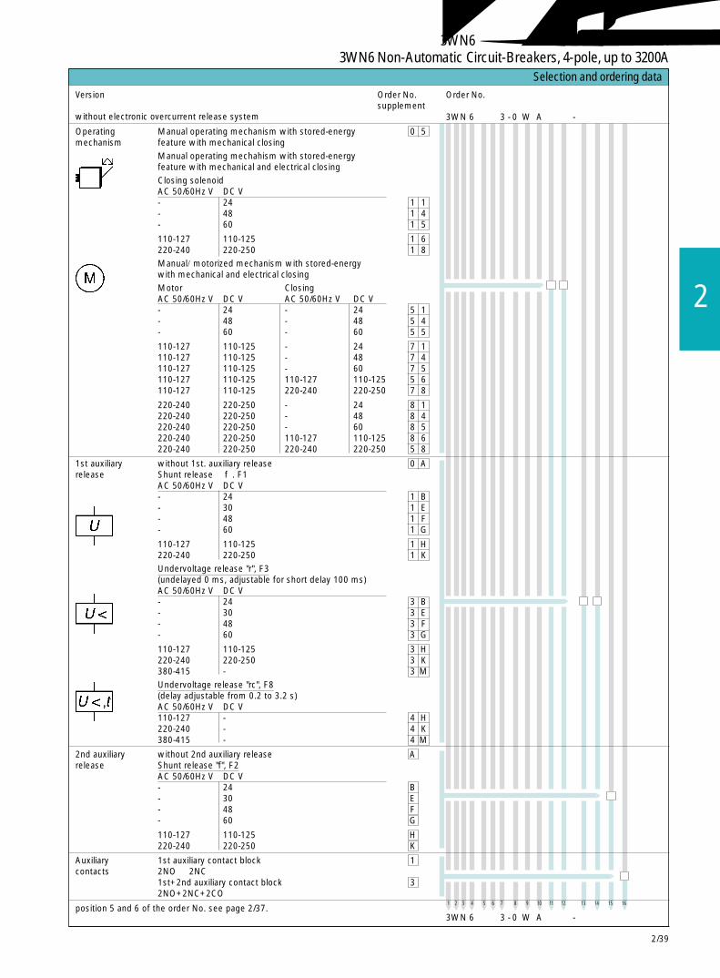
2/39
2
1 2 3 4 5 6 7 8 9 10 11 12 13 14 15 16
Version Order No. Order No.supplement
without electronic overcurrent release system
选型及订货数据 Selection and ordering data
Operating Manual operating mechanism with stored-energy 0 5mechanism feature with mechanical closing
Manual operating mechahism with stored-energyfeature with mechanical and electrical closing
Closing solenoidAC 50/60Hz V DC V- 24 1 1- 48 1 4- 60 1 5
110-127 110-125 1 6220-240 220-250 1 8
Manual/motorized mechanism with stored-energywith mechanical and electrical closing
Motor ClosingAC 50/60Hz V DC V AC 50/60Hz V DC V- 24 - 24 5 1- 48 - 48 5 4- 60 - 60 5 5
110-127 110-125 - 24 7 1110-127 110-125 - 48 7 4110-127 110-125 - 60 7 5110-127 110-125 110-127 110-125 5 6110-127 110-125 220-240 220-250 7 8
220-240 220-250 - 24 8 1220-240 220-250 - 48 8 4220-240 220-250 - 60 8 5220-240 220-250 110-127 110-125 8 6220-240 220-250 220-240 220-250 5 8
1st auxiliary without 1st. auxiliary release 0 Arelease Shunt release “f”. F1
AC 50/60Hz V DC V- 24 1 B- 30 1 E- 48 1 F- 60 1 G
110-127 110-125 1 H220-240 220-250 1 K
Undervoltage release "r", F3(undelayed 0 ms, adjustable for short delay 100 ms)AC 50/60Hz V DC V- 24 3 B- 30 3 E- 48 3 F- 60 3 G
110-127 110-125 3 H220-240 220-250 3 K380-415 - 3 M
Undervoltage release "rc", F8(delay adjustable from 0.2 to 3.2 s)AC 50/60Hz V DC V110-127 - 4 H220-240 - 4 K380-415 - 4 M
2nd auxiliary without 2nd auxiliary release Arelease Shunt release "f", F2
AC 50/60Hz V DC V- 24 B- 30 E- 48 F- 60 G
110-127 110-125 H220-240 220-250 K
Auxiliary 1st auxiliary contact block 1contacts 2NO + 2NC
1st+2nd auxiliary contact block 32NO+2NC+2CO
position 5 and 6 of the order No. see page 2/37.3WN 6 □ □ 3 - 0 W A □ □ - □ □ □ □
3WN 6 □ □ 3 - 0 W A □ □ - □ □ □ □
3WN6负荷隔离开关,4极,至 3200A3WN6 Non-Automatic Circuit-Breakers, 4-pole, up to 3200A
2/40
3WN6断路器,3极和 4极,至 3200A3WN6 Circuit-Breakers, 3 and 4-pole, up to 3200A
用于固定式和抽屉式断路器
通讯模块 用于具有附加功能 2 的 D, E/F, H, J/K, N 和 P 型过 F 0 1电流脱扣器。需要另订 DP/3WN6 "3RK1000" 接口
测量模块 用于具有附加功能 2 的 N 型和 P 型过电流脱扣器。 F 0 5测量模块由带测量功能的通讯模块和外部电压互感器组成。需要另订 DP/3WN6 "3RK1000" 接口
过电流脱扣后自动机械复位 K 0 1
额定短时耐受 适用于 3 极和 4 极断路器,额定电流 630A~1000A K 0 3电流Icw=50kA/1s(AC50/60Hz 时)
脱扣信号发送开关 K 0 71 转换代替 1 常开(1 常开 = 标准型)
带 5 位数的操作 C 0 1次数计数器
在控制面板上的 只用于具有手动 / 电动机储能操作机构的断路器 S 1 3电动机开关
带锁定装置,防 带 3SB1 安全锁, CES 型 S 0 1止未经许可合闸 替代分闸按钮(钥 标准闭锁 No.SSG10或带急停按钮。 匙可在分闸位置 BKS 型 S 0 2对于特殊锁具, 上取出) 标准闭锁 No.S1见第 2/54 页附件 IKON 型 S 0 3
标准闭锁 No.360012K1带锁定装置,最多可用 4 把挂锁 S 2 0(4~8mm钩环直径)用急停按钮(自锁型)替代分闸按钮 S 1 2
带 3SBI 安全锁, CES 型 S 0 5替代带密封盖的 标准闭锁 No. SSG10机械合闸按钮 BKS 型 S 0 6
标准闭锁 No. S1IKON 型 S 0 7标准闭锁 No. 360012K1
用于 CASTELL 锁或 FORTRESS 锁 1)的安装组件 S 1 4从生产厂家处获得的锁:CASTELL 锁(FS2)或 FORTRESS 锁(H31LH/65º/标准)
用于 KIRK - KEY 锁 1)的安装组件 S 1 5
用于 CASTELL、FORTRESS 或 KIRK-KEY锁的锁 S 1 6定装置,当钥匙取出后,钥匙孔被盖住;最多可用4 把挂锁锁住。
用密封盖罩住分 不可以与安全锁组合 S 2 1闸按钮,防止未经许可分闸
用密封盖罩住合 S 2 2闸按钮,防止未经许可合闸
附加功能随断路器同时订购 Accessories for first order-Further versions
要选用以下附加规格,只要在订货号的后面加上“-Z”,和相应的订货码。
订货码 订货号,带 ”-Z”1 2 3 4 5 6 7 8 9 101112 131415163W N 6 . . . _ . . . . . _ . . . . -Z和附加订货码□ □ □ +. . . + . . .
带有附加规格的识别码
-Z
1) 锁可从锁具生产厂家获得。
busI
busI,U,cos
Icw
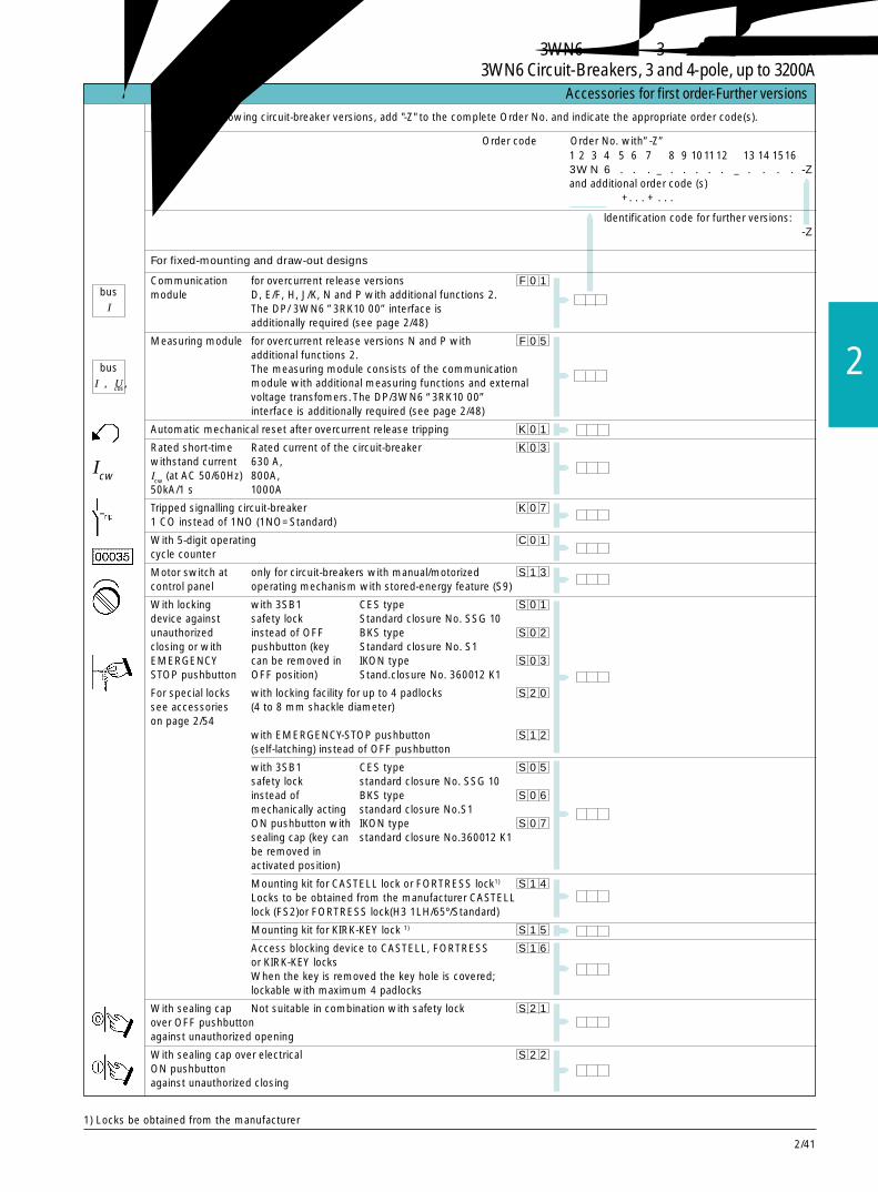
2/41
2
For ordering following circuit-breaker versions, add "-Z" to the complete Order No. and indicate the appropriate order code(s).
附加功能随断路器同时订购 Accessories for first order-Further versions
Order code Order No. with”-Z”1 2 3 4 5 6 7 8 9 101112 13 14 15163W N 6 . . . _ . . . . . _ . . . . -Zand additional order code (s)□ □ □ +. . . + . . .
ldentification code for further versions:-Z
For fixed-mounting and draw-out designs
Communication for overcurrent release versions F 0 1module D, E/F, H, J/K, N and P with additional functions 2.
The DP/ 3WN6 ”3RK10 00” interface isadditionally required (see page 2/48)
Measuring module for overcurrent release versions N and P with F 0 5additional functions 2.The measuring module consists of the communicationmodule with additional measuring functions and externalvoltage transfomers. The DP/3WN6 “3RK10 00”interface is additionally required (see page 2/48)
Automatic mechanical reset after overcurrent release tripping K 0 1
Rated short-time Rated current of the circuit-breaker K 0 3withstand current 630 A,Icw (at AC 50/60Hz) 800A,50kA/1 s 1000A
Tripped signalling circuit-breaker K 0 71 CO instead of 1NO (1NO=Standard)
With 5-digit operating C 0 1cycle counter
Motor switch at only for circuit-breakers with manual/motorized S 1 3control panel operating mechanism with stored-energy feature (S9)
With locking with 3SB1 CES type S 0 1device against safety lock Standard closure No. SSG 10unauthorized instead of OFF BKS type S 0 2closing or with pushbutton (key Standard closure No. S1EMERGENCY can be removed in IKON type S 0 3STOP pushbutton OFF position) Stand.closure No. 360012 K1
For special locks with locking facility for up to 4 padlocks S 2 0see accessories (4 to 8 mm shackle diameter)on page 2/54
with EMERGENCY-STOP pushbutton S 1 2(self-latching) instead of OFF pushbutton
with 3SB1 CES type S 0 5safety lock standard closure No. SSG 10instead of BKS type S 0 6mechanically acting standard closure No.S1ON pushbutton with IKON type S 0 7sealing cap (key can standard closure No.360012 K1be removed inactivated position)
Mounting kit for CASTELL lock or FORTRESS lock1) S 1 4Locks to be obtained from the manufacturer CASTELLlock (FS2)or FORTRESS lock(H3 1LH/65º/Standard)
Mounting kit for KIRK-KEY lock 1) S 1 5
Access blocking device to CASTELL, FORTRESS S 1 6or KIRK-KEY locksWhen the key is removed the key hole is covered;lockable with maximum 4 padlocks
With sealing cap Not suitable in combination with safety lock S 2 1over OFF pushbuttonagainst unauthorized opening
With sealing cap over electrical S 2 2ON pushbuttonagainst unauthorized closing
1) Locks be obtained from the manufacturer
busI
busI,U,cos
Icw
3WN6断路器,3极和 4极,至 3200A3WN6 Circuit-Breakers, 3 and 4-pole, up to 3200A
2/42
用于固定式断路器
锁定装置 当断路器处于合闸状态时防止打开柜门 S 2 5
当柜门打开时防止断路器合闸 S 2 4
用于 3WN6 断路 联锁模块,带一根钢缆(2m 长)。对于 3 台断路器 S 5 3器的相互机械联锁 联锁,需要一根附加钢缆;见第 2/44 页。
锁定装置包括柜 带安全锁 CES 型 S 6 1门上的锁和带钢 标准闭锁 No. SSG10缆(1.5m 长)的 BKS 型 S 6 2联锁模块。 标准闭锁 No. S1
IKON 型 S 6 3防止断路器未经 标准闭锁 No. 360012K1许可合闸 O. M. R.型 S 6 7
标准闭锁 No. 73034
用于 CASTELL 锁的安装组件。 S 6 5从生产厂家处获得的锁:CASTELL 锁(FS2)用于 FORTRESS 的安装组件。 S 6 4从生产厂家处获得的锁:FORTRESS 锁(H31LH/AC65º/标准)
消弧罩盖 用于额定电压>415V 时,防止飞弧。 C 3 5对于主回路母排垂直前置,不需要消弧罩盖
用于抽屉式断路器
锁定装置 带安全锁 CES 型 S 7 1防止移动断路器 标准闭锁 No. SSG10(安全锁防止打 BKS 型 S 7 2开曲柄孔) 标准闭锁 No. S1
IKON 型 S 7 3标准闭锁 No. 360012K1Profalux 型 S 7 5Ronis 型 S 7 6O. M. R 型 S 7 7标准闭锁 No. 73034
附加功能随断路器同时订购 Accessories for first order-Further versions
要选用以下附加规格,只要在订货号的后面加上“-Z”,和相应的订货码
订货码 订货号,带 ”-Z”1 2 3 4 5 6 7 8 9 101112 131415163W N 6 . . . _ . . . . . _ . . . . -Z和附加订货码□ □ □ +. . . + . . .
带有附加规格的识别码
-Z
3WN6断路器,3极和 4极,至 3200A3WN6 Circuit-Breakers, 3 and 4-pole, up to 3200A
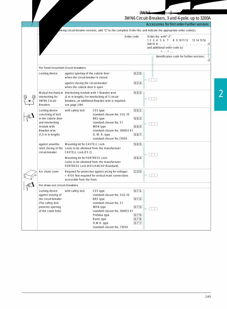
2/43
2
For ordering following circuit-breaker versions, add "-Z" to the complete Order No. and indicate the appropriate order code(s).
附加功能随断路器同时订购 Accessories for first order-Further versions
Order code Order No. with”-Z”1 2 3 4 5 6 7 8 9 101112 13 14 15163W N 6 . . . _ . . . . . _ . . . . -Zand additional order code (s)□ □ □ +. . . + . . .
ldentification code for further versions:-Z
For fixed-mounted circuit-breakers
Locking device against opening of the cubicle door S 2 5when the circuit-breaker is closed
against closing the circuit-breaker S 2 4when the cubicle door is open
Mutual mechanical Interlocking module with 1 Bowden wire S 5 3interlocking for (2 m in length), For interlocking of 3 circuit-3WN6 Circuit- breakers, an additional Bowden wire is required;Breakers see page 2/44.
Locking device with safety lock CES type S 6 1consisting of lock standard closure No. SSG 10in the cubicle door BKS type S 6 2and interlocking standard closure No. S1module with IKON type S 6 3Bowden wire standard closure No. 360012 K1(1,5 m in length) O. M. R. type S 6 7
standard closure No.73034
against unautho- Mounting kit for CASTELL Lock. S 6 5rized closing of the Locks to be obtained from the manufacturercircuit-breaker CASTELL Lock (FS 2)
Mounting kit for FORTRESS Lock. S 6 4Locks to be obtained from the manufacturerFORTRESS Lock (H31LH/AC65o/Standard)
Arc chute cover Required for protection against arcing for voltages C 3 5> 415V. Not required for vertical main connectionsaccessible from the front.
For draw-out circuit-breakers
Locking device with safety lock CES type S 7 1against moving of standard closure No. SSG 10the circuit-breaker BKS type S 7 2(The safety lock standard closure No. S1prevents opening IKON type S 7 3of the crank hole) standard closure No. 360012 K1
Profalux type S 7 5Ronis type S 7 6O.M.R. type S 7 7standard closure No. 73034
3WN6断路器,3极和 4极,至 3200A3WN6 Circuit-Breakers, 3 and 4-pole, up to 3200A

2/44
用于带导向框架的抽屉式断路器用于导向框架
总线连接电缆, 连接于导向框架和接口 DP/3WN6 之间,包括信号 R 3 9用于通讯(如果导 发送开关(用于传送断路器本体是否在导向框架内)向框架另外单独订购,需此项)
额定电流的主 主回路连接前置, R 0 2回路连接 顶部和底部,双孔,按照 DIN 43673 标准详见第 2/7页
主回路连接前置, R 0 3顶部和底部,单孔
主回路连接后置, R 0 7顶部和底部,垂直
带位置信号发送 运行位置 试验位置 退出位置开关(由抽屉式断 1NO + 1NC 1NO + 1NC 1NO + 1NC R 1 3路器操作) 3NO + 3NC 2NO + 2NC 1NO + 1NC R 1 4
安全挡板,两部分 R 2 0
3WN6 断路器的 联锁模块带一根钢缆(2m 长)。 R 5 3相互机械联锁 对于 3 台断路器联锁,需要一根附加钢缆;见第 2/22 页。
锁定装置 带安全锁 CES 型 R 6 1包括柜门上的锁 标准闭锁 No. SSG10和带钢缆(1.5m长) BKS 型 R 6 2的联锁模块 标准闭锁 No. S1防止断路器未经许 IKON 型 R 6 3可合闸,在运行位 标准闭锁 No. 360012K1置有效 O. M. R 型 R 6 7
标准闭锁 No. 73034
用于 CASTELL 锁的安装组件 R 6 5从生产厂家处获得的锁:CASTELL 锁(FS2)用于 FORTRESS 锁的安装组件 R 6 4从生产厂家处获得的锁:FORTRESS 锁(H31LH/AC65º/ 标准)
锁定装置 带安全锁 CES 型 R 8 1防止在退出位置 标准闭锁 No. SSG10移动断路器本体 BKS 型 R 8 2
标准闭锁 No. S1IKON 型 R 8 3标准闭锁 No. 360012K1Profalux 型 R 8 5Ronis 型 R 8 6O. M. R 型 R 8 7标准闭锁 No.73034
锁定装置 当断路器在运行位置时防止打开柜门 R 3 0
当柜门打开时防止断路器合闸(只在运行位置有效) R 4 0
当柜门打开时防止断路器被移动 R 5 0(在退出、试验和有效位置都有效)
消弧罩盖 用于额定电压>415V 时,防止飞弧。对于主 R 3 5回路母排垂直前置,不需要此项。
附加功能随断路器同时订购 Accessories for first order-Further versions要选用以下附加规格,只要在订货号的后面加上“-Z”,和相应的订货码。
订货码订货号,带 ”-Z”1 2 3 4 5 6 7 8 9 10 11 12 13 14 15 163 W N 6 . 8 . - . . . . . - . . . . -Z和附加订货码□ □ □ + . .. + . . .导向框架的订货号,带 ”-Z”1 2 3 4 5 6 7 8 9 10 11 123 W X 3 6 8 3 - . A . . 0 -Z和附加订货码□ □ □ +. . . + . . .+ . . .
带有附加规格的识别号 -Z
带导向框架的抽屉式断路器 其他规格
导向框架(如果导向框架另外单独订购)
3WN6断路器,3极和 4极,至 3200A3WN6 Circuit-Breakers, 3 and 4-pole, up to 3200A
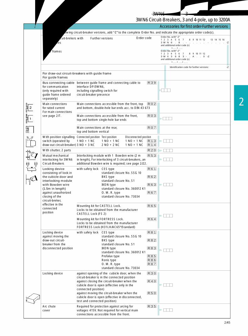
2/45
2
For ordering following circuit-breaker versions, add "-Z" to the complete Order No. and indicate the appropriate order code(s).
附加功能随断路器同时订购 Accessories for first order-Further versions
Order No. with”-Z”1 2 3 4 5 6 7 8 9 10 11 12 13 14 15 163 W N 6 . 8 . - . . . . . - . . . . -Zand additional order code (s)□ □ □ +. . . + . . .Order No. with”-Z”1 2 3 4 5 6 7 8 9 10 11 123 W X 3 6 8 3 - . A . . 0 -Zand additional order code (s)□ □ □ +. . . + . . .+ . . .
ldentification code for further versions: -Z
For draw-out circuit-breakers with guide frameFor guide frames
Bus connecting cable between guide frame and connecting cable to R 3 9for communication interface DP/3WN6,(only required with including signalling switch forguide frame ordered circuit-breaker presenceseparately)
Main connections Main connections accessible from the front, top R 0 2for rated current and bottom, double-hole bar ends acc. to DIN 43 673For main connectionssee page 2/7. Main connections accessible from the front, R 0 3
top and bottom single-hole bar ends
Main connections at the rear, R 0 7top and bottom vertical
With position signalling Connected position Test position Disconnected postionswitch (operated by 1 NO + 1 NC 1 NO + 1 NC 1 NO + 1 NC R 1 3draw-out circuit-breaker) 3 NO + 3 NC 2 NO + 2 NC 1 NO + 1 NC R 1 4
With shutter, 2 parts R 2 0
Mutual mechanical Interlocking module with 1 Bowden wire (2 m R 5 3interlocking for 3WN6 in length), For interlocking of 3 circuit-breakers, anCircuit-Breakers additional Bowden wire is required; see page 2/22.
Locking device with safety lock CES type R 6 1consisting of lock in standard closure No. SSG 10the cubicle door and BKS type R 6 2interlocking module standard closure No. S1with Bowden wire IKON type R 6 3(1.5m in length) standard closure No. 360012 K1against unauthorized O. M. R. type R 6 7closing of the standard closure No. 73034circuit-breker,effective in the Mounting kit for CASTELL Lock. R 6 5connected Locks to be obtained from the manufacturerposition CASTELL Lock (FS 2)
Mounting kit for FORTRESS Lock. R 6 4Locks to be obtained from the manufacturerFORTRESS Lock (H31LH/AC65º/Standard)
Locking device with safety lock CES type R 8 1against moving the standard closure No. SSG 10draw-out circuit- BKS type R 8 2breaker from the standard closure No. S1disconnected position IKON type R 8 3
standard closure No. 360012 K1Profalux type R 8 5Ronis type R 8 6O. M. R. type R 8 7standard closure No. 73034
Locking device against opening of the cubicle door, when the R 3 0circuit-breaker is in the connected positionagainst closing the circuit-breaker when the R 4 0cubicle door is open (effective only in theconnected position)against moving the circuit-breaker when the R 5 0cubicle door is open (effective in disconnected,test and connected position)
Arc chute Required for protection against arcing for R 3 5cover voltages 415V. Not required for vertical main
connections accessible from the front.
Draw-out circuit-brekers with Further versionsguide frames
Guide frames
Order code
3WN6断路器,3极和 4极,至 3200A3WN6 Circuit-Breakers, 3 and 4-pole, up to 3200A
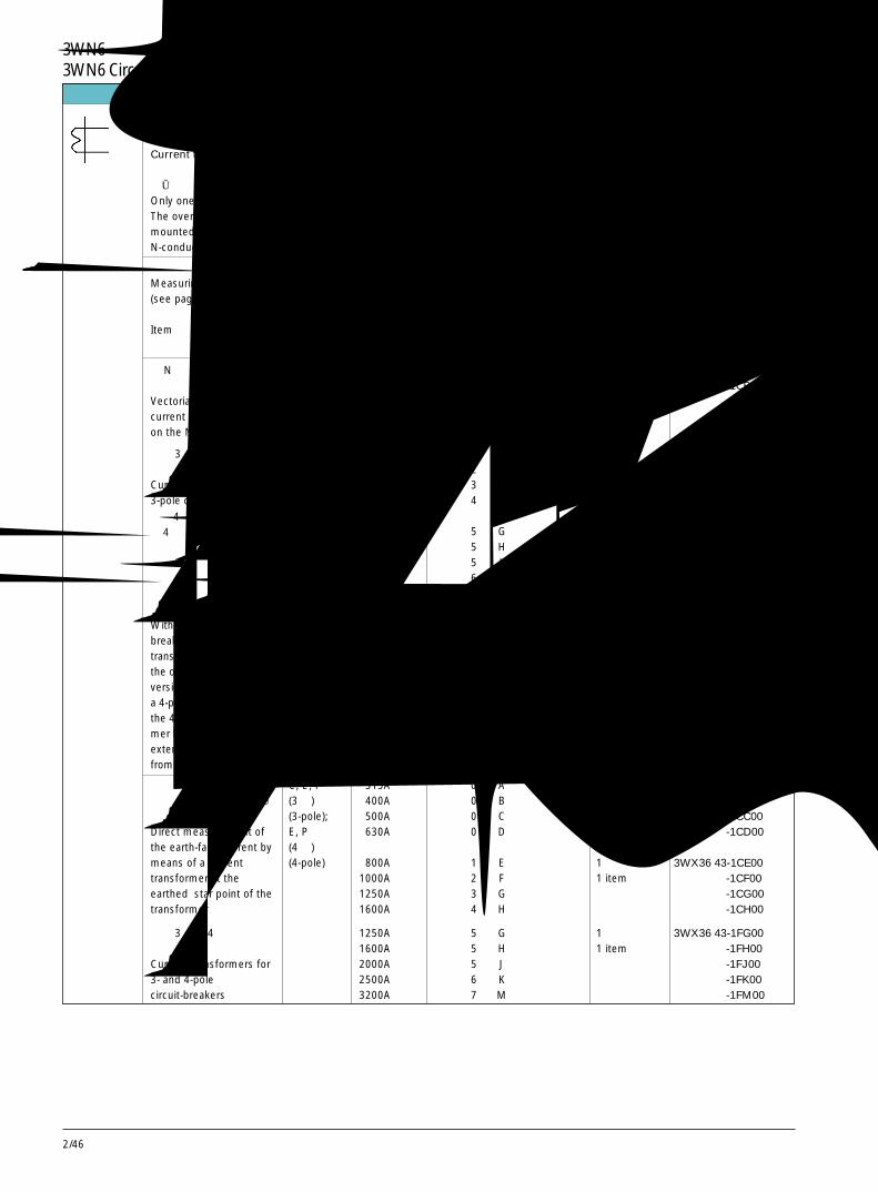
2/46
在 N 导线上用电流互 C, D, E 315A 0 A 1 件 3WX36 43-1CA00感器进行矢量求和 400A 0 B 1 item -1CB00Vectorial summation with 500A 0 C -1CC00current transformer 630A 0 D -1CD00on the N conductor
用于 3 极断路器的 800A 1 E 1 件 3WX36 43-1CE00电流互感器 1000A 2 F 1 item -1CF00Current transformers for 1250A 3 G -1CG003-pole circuit-breakers 1600A 4 H -1CH00
1250A 5 G 1 件 3WX36 43-1FG001600A 5 H 1 item -1FH002000A 5 J -1FJ002500A 6 K -1FK003200A 7 M -1FM00
N, P 630A 0 D 1 件 3WX3643-2BA00800A 1 E 1 item
1000A 2 F1250A 3 G1600A 4 H
2000A 5 J 1 件 3WX3643-2FA002500A 6 K 1 item3200A 7 M
在变压器星型接地点处用 C, E, P 315A 0 A 1 件 3WX36 43-1CA00电流互感器直接测量接地 (3 极) 400A 0 B 1 item -1CB00故障电流 (3-pole); 500A 0 C -1CC00Direct measurement of E, P 630A 0 D -1CD00the earth-fault current by (4 极)means of a current (4-pole) 800A 1 E 1 件 3WX36 43-1CE00transformer at the 1000A 2 F 1 item -1CF00earthed star point of the 1250A 3 G -1CG00transformer 1600A 4 H -1CH00
用于 3 极和 4 极断路器的 1250A 5 G 1 件 3WX36 43-1FG00电流互感器 1600A 5 H 1 item -1FH00Current transformers for 2000A 5 J -1FJ003- and 4-pole 2500A 6 K -1FK00circuit-breakers 3200A 7 M -1FM00
用于固定式和抽屉式断路器 / For fixed-mounted and draw-out circuit-breakers
用于N导线过载保护和接地故障保护的电流互感器Current transformers for overload protection of the N conductor and for earth-fault protection两种测量方法中只可选用一种方法,当电流互感器安装在 N 导线上时,对 N 导线的过载保护才有效。接地故障电流经相电流和 N 导线电流矢量求和得出。对于 P 型过电流脱扣器,两种测量方法可同时使用。Only one of the two measuring methods is feasible in conjunction with the overcurrent release.The overload protection of the N conductor is effective as soon as the current transformer ismounted on the N conductor.The earth-fault current is calculated via a summation of the phase andN-conductor currents.With the release version P, both the methods can be used at the same time.
测量方法(见第 2/19页) 过电流 电流互感器 断路器订货号第 5 位和 每台断路器 每 1 件Measuring method 脱扣器类型 原边额定电流 第 9 位的代号 所需数量 Per item(see page 2/19) Overcurrent Transformer 3WN6 □..-. □...-.... Quantity 订货号项目 release primary rated 5th and 9th position of curcuit- required per Order No.Item version current breaker Order No. circuit-breaker
3WN6 □..-. □...-....
用于改装的附件 Accessories for first order and retrofitting
对于4极断路器,已内装有第4个电流互感器。如果4极断路器配置 E 型过电流脱扣器,则应从右表中选择第4个电流互感器,该电流互感器必须装在断路器外部。With 4-pole circuit-breakers, the 4th currenttransformer is built-in. lfthe overcurrent releaseversion E is selected witha 4-pole circuit-breaker,the 4th current transfor-mer has to be mountedexternally and be chosenfrom the adjacent table.
3WN6断路器,3极和 4极,至 3200A3WN6 Circuit-Breakers, 3 and 4-pole, up to 3200A
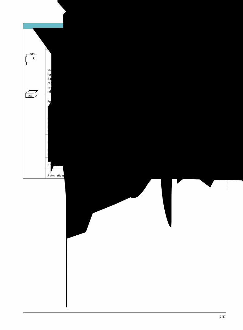
2/47
2
项目 / ltem 额定控制电压 /Rated control supply voltage 所需数量 每一台或一套的订货号额定工作电压 /Rated operational voltage Ouantity Per 1 set or 1 item
required Order No.
AC 50/60Hz DC
储能装置 110-127 V 110-115 V 1 件 3WX31 56-1JG01用于分励脱扣器 220-240 V 220-250 V 1 item 3WX31 56-1JJ01额定控制电压必须与分励脱扣器的额定控制电压一致Storage devicefor shunt releaseRated control supply voltage mustcorrespond to the rated controlsupply voltage of the shuntrelease
过电流脱扣器的功能测试仪 110-127/220-240 V - 1 台 3WX36 47-5JA01Function tester for ovecurrent release 1 item适用于 B, C, D, E, F, G, V, N, P 型脱扣器也适用于 3WN1 和 3WS1 断路器的过电流脱扣器for release versions B, C, D, E, F, G, V,N, P also suitable for overcurrentreleases of 3WN1 and 3WS1circuit-breakers
电源转换装置 1 台 3WX36 66-7JA00Network-switching control unit 1 item用于两台固定式断路器或抽屉式断路器的自动电源转换for automatic switching of two fixed-mountedor draw-out circuit-breakers
门密封框 防护等级 IP 54 1 件 3WX36 86-0JA00Door sealing frame for degree of protection IP 54 1 item
自动复位装置 1 件 3WX36 46-2JA00Automatic mechanical resetting device 1 item
用于改装的附件 Accessories for first order and retrofitting
3WN6断路器,3极和 4极,至 3200A3WN6 Circuit-Breakers, 3 and 4-pole, up to 3200A

2/48
用于改装的附件 Accessories for first orders and retrofitting
描述/Description 所需数量 订货号(参见“具有通讯能力的断路器”一章)/(see also "Communication-capable order Per unitcircuit-breaker" in catalog) Quantity Order No.
用于固定式和抽屉式断路器 / For fixed-mounting and draw-out circuit-breakers
DP/3WN6 接口 每台具有通讯能力的 3WN6 断路器需一个 1 个 3RK10 00-0JC80-0BA2lnterface connection Required once for each communication capable 1 itemDP/3WN6 circuit-breaker
PROFIBUS 连接器 将接口联接至 PROFIBUS 1 根 6ES7 972-0BB20-0XA0PROFIBUS connector For connecting the interface to the PROFIBUS 1 item
DC 24 V 电源 用于接口 DP/3WN6 的供电 1 台 4AV2 系列Power supply DC 24 V For interface DP/3WN6 1 item for instance 4AV2.
系统手册 将 3VL,3WN6,3WN1/3WS1 连接至 PROFIBUS-DP 1 册 E20001-P285-A644-V1System manual 实现通讯的方法
Connection of circuit-breakers 3VL, 3WN6, 3WN1/3WS1 1 itemto the PROFIBUS-DP for communication
软件 推荐用于 SIMATIC S5 和 S7 实现通讯的编程工具,3.5" 软盘 1 套 3RK18 00-0AA00-0AA00Software module Recommended for SIMATIC S5 and S7; programming help 1 item
for the development of communication, 3.5" diskettes
手持式控制单元 用于 3WN6 断路器的参数设置,运行监控,适用于带 D、E/F、 1 台 3WX36 47-6JA00Hand-held control unit H、J/K、N/P 型过电流脱扣器和具有通讯能力的电动机保护
和控制装置 SIMOCODE-DP 3UF50For parameterization operation and monitoring of 3WN6 1 itemcircuit-breakers with overcurrent releases D, E/F, H, J/K, N/Pand communication-capable motor protection and control unitSIMOCODE-DP 3UF50
匹配器用于手持式控制单元 3WX3647-6JA00 1 件 3WX36 47-6JA01Adapter for hand-held control unit 3WX3647-6JA00 1 item
电源当 3WN6 断路器不另外提供直流 24V 电源时需此项 1 台 3WX36 47-6JA02Power supply required when the 3WN6 circuit breaker 1 itemis not additionally supplied with 24 V DC
3WN6断路器,3极和 4极,至 3200A3WN6 Circuit-Breakers, 3 and 4-pole, up to 3200A
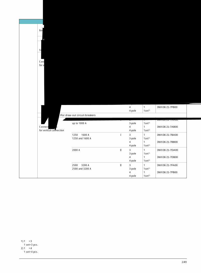
2/49
2
用于改装的附件
项目 额定电流 尺寸等级 极数 所需数量 订货号ltem Rated current Size Number Quantity Per 1 set
of poles required Order No.
用于固定式断路器 /For fixed-mounted circuit-breakers
支持托架 1 套 3WX36 81-0JA00包括断路器固定螺栓 1 setSupporting brackets including screws for the fixed-mounted circuit-breaker
连接母排 至 1000 A I 3 极 1 套 3WX36 21-7AA00用于垂直连接 up to 1000 A 3-pole 1set1)
Connecting bars 4 极 1 套 3WX36 21-7AB00for vertical connection 4-pole 1set2)
1250 和 1600 A I 3 极 1 套 3WX36 21-7BA001250 and 1600 A 3-pole 1set1)
4 极 1 套 3WX36 21-7BB004-pole 1set2)
2000 A II 3 极 1 套 3WX36 21-7DA003-pole 1set1)
4 极 1 套 3WX36 21-7DB004-pole 1set2)
2500 和 3200 A II 3 极 1 套 3WX36 21-7FA002500 and 3200 A 3-pole 1set1)
4 极 1 套 3WX36 21-7FB004-pole 1set2)
用于抽屉式断路器 /For draw-out circuit-breakers
连接母排 至 1000 A I 3 极 1 套 3WX36 21-7AA00用于垂直连接 up to 1000 A 3-pole 1set1)
Connecting bars 4 极 1 套 3WX36 21-7AB00for vertical connection 4-pole 1set2)
1250 和 1600 A I 3 极 1 套 3WX36 21-7BA001250 and 1600 A 3-pole 1set1)
4 极 1 套 3WX36 21-7BB004-pole 1set2)
2000 A II 3 极 1 套 3WX36 21-7DA003-pole 1set1)
4 极 1 套 3WX36 21-7DB004-pole 1set2)
2500 和 3200 A II 3 极 1 套 3WX36 21-7FA002500 and 3200 A 3-pole 1set1)
4 极 1 套 3WX36 21-7FB004-pole 1set2)
1) 1 套 =3 件1 set=3 pcs.
2) 1 套 =4 件1 set=4 pcs.
Accessories for first orders and retrofitting
3WN6断路器,3极和 4极,至 3200A3WN6 Circuit-Breakers, 3 and 4-pole, up to 3200A
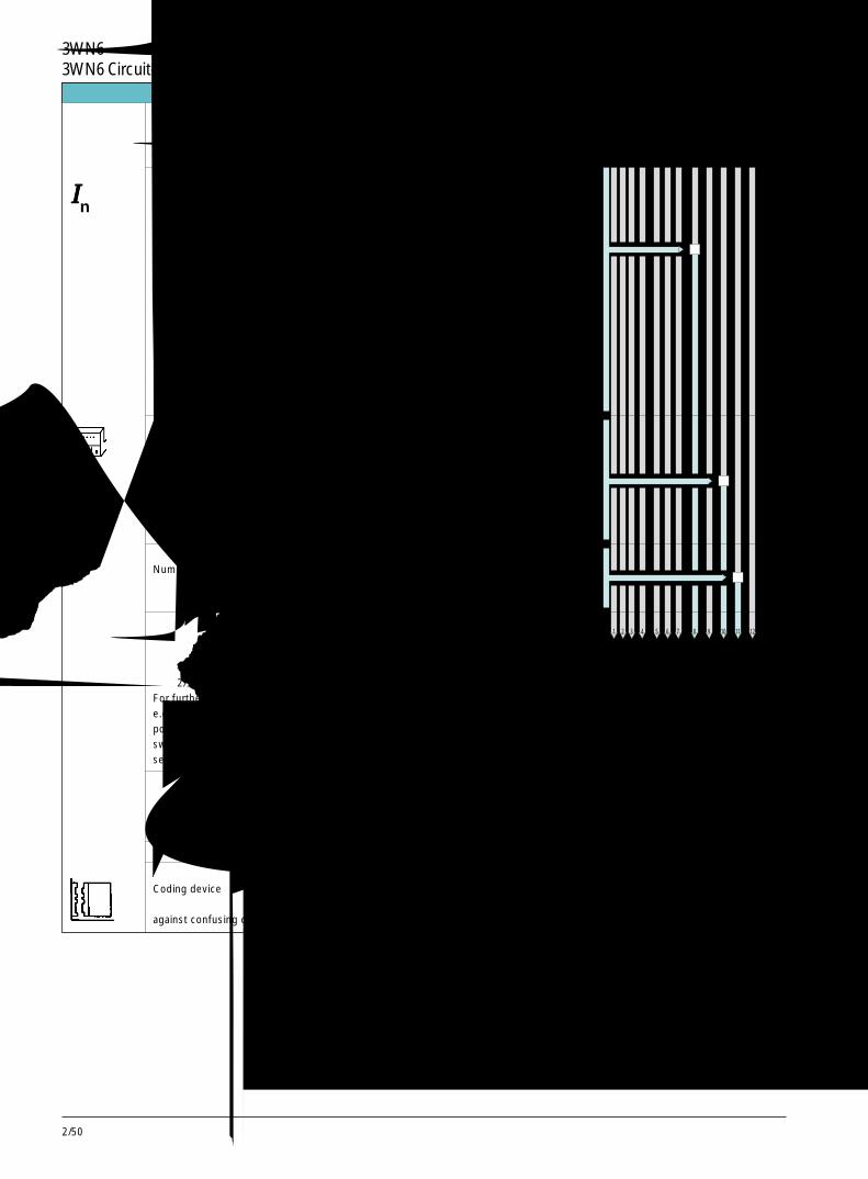
2/50
抽屉式辅助 1 个辅助接线端子块 B接线端子块 1 auxiliary draw-out connector(所需数量见下页) 2 个辅助接线端子块 CAuxiliary draw-out 2 auxiliary draw-out connectorsconnectors 3 个辅助接线端子块 D(For the number 3 auxiliary draw-out connectorsneeded see next page) 4 个辅助接线端子块 E
4 auxiliary draw-out connectors
极数 3 极 1Number of poles 3-pole
4 极 34-pole
对于其他型式的导向框架,如:主回路前置连接、位置信号发送开关、安全挡板,见第 2/9 页For further versionse.g.front connections,position signallingswitches, shutters,see page 2/9.
描述 每台断路器 每一套所需数量 订货号
Description Quantity required Per 1 setper circuit-breaker Order No.
用于导向框架的附件 / Accessories for guide frames
编码装置 1 套 3WX3662- 1JC00Coding device 1 set防止同一个开关柜内的相同尺寸的断路器混淆against confusing circuit-breakers of equal size in a cubicle
用于改装的附件 Accessories for first orders and retrofits类型 订货号的补充 订货号Version Order No. Order No.导向框架,标准型 supplementGuide frames, standard versions
抽屉式断路器 630A,尺寸等级 I 0的额定电流 In size IRated current of the 800A,尺寸等级 I 1draw-out circuit-breaker size I
1000A,尺寸等级 I 2size I
1250A,尺寸等级 I 3size I
1600A,尺寸等级 I 4size I
2000A,尺寸等级 II 5size II
2500A,尺寸等级 II 6size II
3200A,尺寸等级 II 7size II
3WX 3 6 8 3 - □ A □ □ 0
3WX 3 6 8 3 - □ A □ □ 0
1 2 3 4 5 6 7 8 9 10 11 12
IIIIIn
3WN6断路器,3极和 4极,至 3200A3WN6 Circuit-Breakers, 3 and 4-pole, up to 3200A
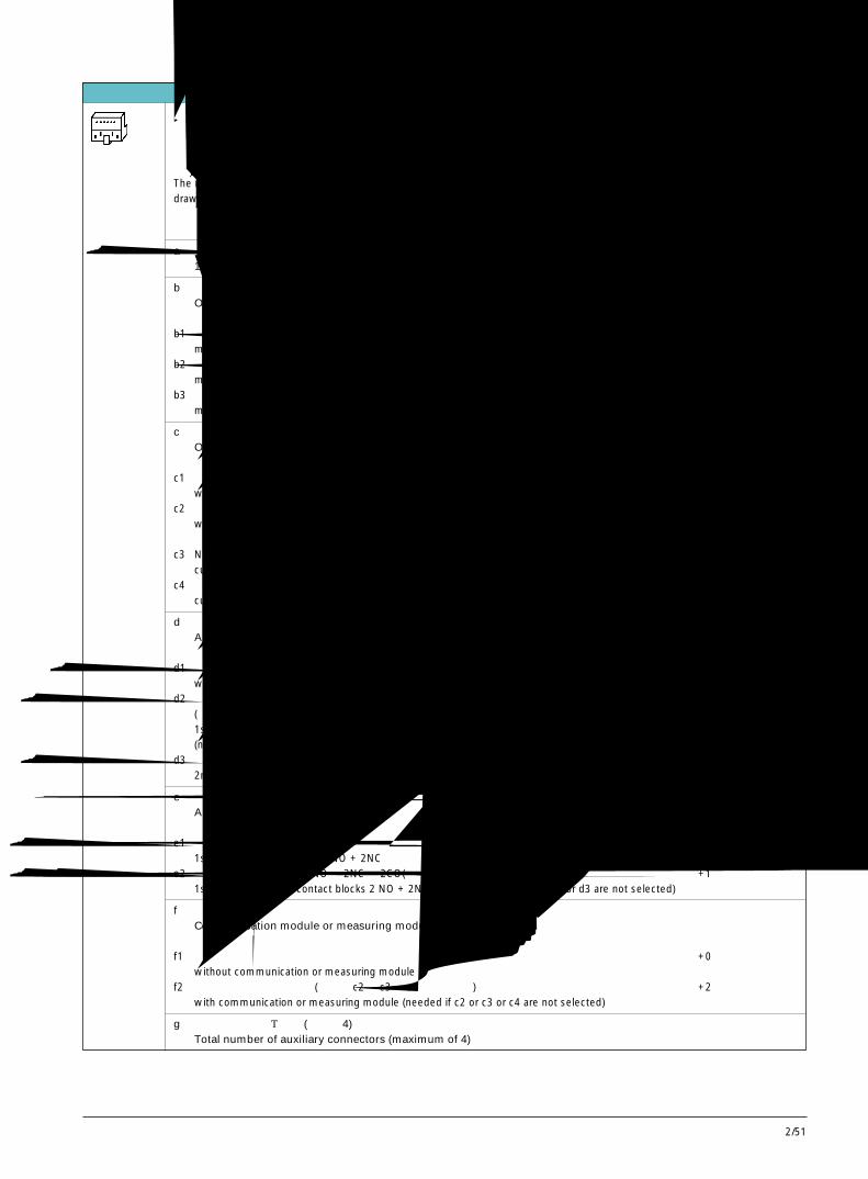
2/51
2
抽屉式辅助接线端子块的 ● 操作机构类型数量取决于: ● 过电流脱扣器有 /无附加功能
● 辅助脱扣器的类型和数量● 辅助触头块的数量
The required number of auxiliary ● Type of operating mechanismdraw-out connectors depends on: ● Overcurrent releases with/without additional functions, with/without current transformers
● Type and number of auxiliary releases● Number of auxiliary contact blocks
a 用于标准信号的第一个辅助接线端子块,总是需要的 11 st auxiliary connector, for standard signals, always required
b 操作机构Operating mechanisms
b1 手动储能,机械合闸 +0manual operating mechanism with stored-energy feature with mechanical closing
b2 手动储能,机械合闸和电气合闸 +1manual oper. mechanism with stored-energy feature with mechanical and electrical closing
b3 手动 / 电动机储能,机械合闸和电气合闸 +1manual/motorized oper. mech. with stored-energy feature with mech. and electr. closing
c 过电流脱扣器Overcurrent releases
c1 带基本功能 +0with basic functions
c2 带附加功能 1 或 2 +2with additional functions 1 or 2
c3 N 导线上的电流互感器(如未选择 c2,则带 N 导线保护的 3 极断路器需计此项) +1current transfomer on N conductor (needed for 3-pole circuit-breakers if c2 is not selected)
c4 变压器星型接点处的电流互感器(如未选择 c2,需计此项) +1current transfomer at the star point of the transfomer (needed if c2 is not selected)
d 辅助脱扣器Auxiliary releases
d1 带 / 不带第一辅助脱扣器(分励脱扣器“f”,F1;欠压脱扣器“r”,F3) +0with/without 1st auxiliary release (shunt release "f" , F1; undervoltage release "r", F3)
d2 带第一辅助脱扣器(延时型欠电压脱扣器“rc”,F8) +1(如没选 b2 或 b3,需计此项)1st auxiliary release (delayed undervoltage release "rc", F8)(needed if b2 or b3 is not selected)
d3 带第二辅助脱扣器(分励脱扣器“f”,F2;如没选 b2 或 b3,需计此项) +12nd auxiliary release (shunt release "f", F2, needed if b2 or b3 are not selected)
e 辅助触头Auxiliary releases
e1 第一辅助触头块 2NO + 2NC +01st auxiliary contact block 2 NO + 2NC
e2 第一和第二辅助触头块 2NO + 2NC + 2CO(如没选 b2 或 b3或 d3,需计此项) +11st and 2nd auxiliary contact blocks 2 NO + 2NC + 2 CO (needed if b2 or b3 or d3 are not selected)
f 通讯模块或测量模块Communication module or measuring module
f1 不带通讯模块或测量模块 +0without communication or measuring module
f2 带有通讯模块或测量模块(如没选 c2 或 c3 或 c4,需计此项) +2with communication or measuring module (needed if c2 or c3 or c4 are not selected)
g 辅助接线端子的总数量(最多为 4)Total number of auxiliary connectors (maximum of 4)
用于改装的附件 Accessories for first orders and retrofits
3WN6断路器,3极和 4极,至 3200A3WN6 Circuit-Breakers, 3 and 4-pole, up to 3200A
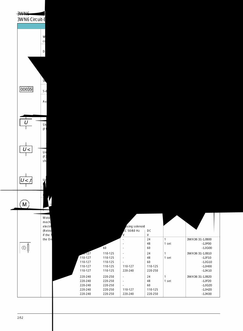
2/52
3WN6断路器,3极和 4极,至 3200A3WN6 Circuit-Breakers, 3 and 4-pole, up to 3200A用于改装的附件 Accessories for first orders and retrofits
当改装断路器时,断路器侧面和铭牌上的订货号应按照安装说明相应更改。When retrofitting these circuit-breakers, the Order No. of the circuit-breaker on the name plate on the controlconsole and the circuit-breaker side should be supplemented according to the mounting instructions.
描述 每台断路器 每一套或每一件Description 所需数量 订货号
Quantityrequired per Per 1 set or 1 itemcircuit-breaker Order No.
用于固定式和抽屉式断路器 /For fixed-mounted and draw-out circuit-breakers
罩住分闸或合闸按钮的密封盖,防止未经许可分闸或合闸 1 个 3WX36 63-1JK00Sealing cap over OFF or ON pushbutton against unauthorized opening or closing 1 item
带 5 位数的操作次数计数器 1 个 3WX36 64-0CA005-digit operating cycle counter 1 item
辅助脱扣器 1) 额定控制电压Auxiliary releases 1) Rated control supply voltage
AC 50/60Hz DCV V
分励脱扣器“f”用作第 1 和第 2 辅助脱 - 24 1 个 3WX36 51-1JB00扣器(F1,F2)及合闸线圈(Y1) - 30 1 item -1JE00Shunt release "f" for 1st and 2nd aux. releases - 48 -1JF00(F1, F2) and closing solenoid (Y1) - 60 -1JG00
110-127 110-125 -1JH00220-240 220-250 -1JK00
欠电压脱扣器“r” (F3) - 24 1 个 3WX36 53-1JB00瞬时 0ms,短延时 100ms - 30 1 item -1JE00Undervoltage release "r" - 48 -1JF00(F3) instantaneous 0 ms, - 60 -1JG00short-time-delay 100 ms 110-127 110-125 -1JH00
220-240 220-250 -1JK00380-415 - -1JM00
欠电压脱扣器“rc” (F8)延时可调:0.2 ~ 3.2s 110-127 - 1 个 3WX36 54-1JH00Undervoltage release "rc" (F8) delay adjustable 220-240 - 1 item -1JK00from 0.2 to 3.2s 380-415 - -1JM00
辅助触头 1) 2 转换 1 件 3WX36 16-1CE00Auxiliary switch1) 2 CO 1 set
电动机操作机构和电气 包括电动机、合闸线圈(Y1)、电气合闸按钮和连接线合闸 1) consisting of motor, closing solenoid (Y1), electrical(如果订货号的第 11 ON pushbutton and wiring位为 0,则可以改装) 额定控制电压Motorized operating Rated control supply voltagemechanism and 电动机 合闸线圈electrical closing 1) Motor Closing solenoid(Retrofitting is possible AC 50/60Hz DC AC 50/60 Hz DCif the 11th position of V V V Vthe Order No.is "0") - 24 - 24 1 套 3WX36 31-1JB00
- 48 - 48 1 set -1JF00- 60 - 60 -1JG00
110-127 110-125 - 24 1 套 3WX36 31-1JB10110-127 110-125 - 48 1 set -1JF10110-127 110-125 - 60 -1JG10110-127 110-125 110-127 110-125 -1JH00110-127 110-125 220-240 220-250 -1JK10
220-240 220-250 - 24 1 套 3WX36 31-1JB20220-240 220-250 - 48 1 set -1JF20220-240 220-250 - 60 -1JG20220-240 220-250 110-127 110-125 -1JH20220-240 220-250 220-240 220-250 -1JK00
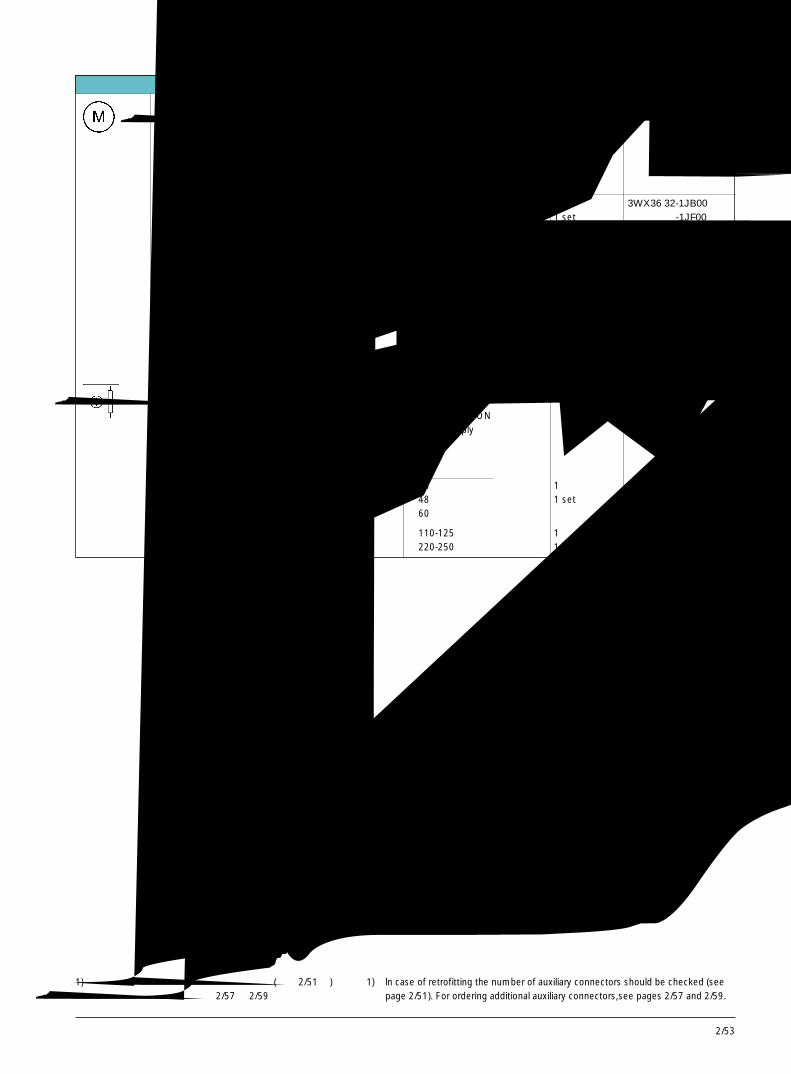
2/53
2
用于改装的附件 Accessories for first orders and retrofits
电动机操作机构 1) 适用条件:断路器订货号中 包括电动机和连接线(关于改装可能性, 的第 11 和 12 位如下: 电动机的额定控制电压见右表) Precondition: 11th + 12th consisting of motor and wiringMotoried operating positions of the Order No. rated contol supply voltagemechanism1) of the circuit-breker of the motor(Retrofitting is possible. 3WN6...-...□□ -... AC 50/60 Hz DCFor conditions see V Vadjacent table) 1 1 - 24 1 套 3WX36 32-1JB00
1 4 - 48 1 set -1JF001 5 - 60 -1JG00
1 1 110-127 110-125 1 套 3WX36 32-1JH001 4 1 set1 51 6
1 1 220-240 220-250 1 套 3WX36 32-1JK001 4 1 set1 51 61 8
电气合闸 1) 包括合闸线圈(Y1)、电气合闸按钮和连接线(如果订货号的第 合闸线圈(Y1)的额定控制电压11 位为“0”,则 consisting of closing solenoid (Y1), electrical ON可以改装) pushbutton and wiring; rated control supplyElectrical closing1) voltage of the closing solenoid (Y1)(Retrofitting is AC 50/60 Hz DCpossible if the 11th V Vposition of the Order - 24 1 套 3WX36 33-1JB00No. of the - 48 1 set -1JF00circuit-breaker is "0") - 60 -1JG00
110-127 110-125 1 套 3WX36 33-1JH00220-240 220-250 1 set -1JK00
1) 若要改装,应核对辅助接线端子块的数量(见第 2/51页)。订购额外接线端子块,见第 2/57 和 2/59 页。
1) ln case of retrofitting the number of auxiliary connectors should be checked (seepage 2/51). For ordering additional auxiliary connectors,see pages 2/57 and 2/59.
3WN6断路器,3极和 4极,至 3200A3WN6 Circuit-Breakers, 3 and 4-pole, up to 3200A
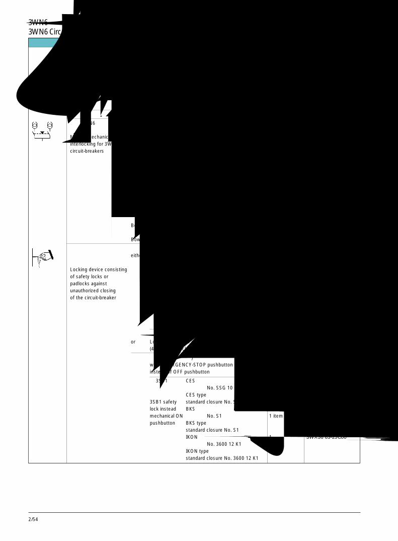
2/54
3WN6断路器,3极和 4极,至 3200A3WN6 Circuit-Breakers, 3 and 4-pole, up to 3200A
当改装断路器时,断路器侧面和铭牌上的订货号应按照安装说明相应更改。When retrofitting these circuit-breakers, the Order No. the circuit-breaker on the name plate on the controlconsole and on the circuit-breaker side should be supplemented according to the mounting instructions.
描述 每台断路器 每一套或每一件Description 所需数量 订货号
Quantity Per 1 set or 1 itemrequired percircuit-breaker Order No.
用于固定式和抽屉式断路器 /For fixed-mounted and draw-out circuit-breakers
用于 3WN6 断路器的 1 个联锁模块和 1 根钢缆(2m 长)相互机械联锁 1 interlocking module with 1 Bowden wire (2 m in length)
用于固定式断路器 1 套 3WX36 66-1JA00For a fixed-mounted circuit-breaker 1 item用于抽屉式断路器 1 套 -2JA00For a draw-out circuit-breaker 1 item
三台断路器的联锁,每台断路器需一根附加的钢缆。For interlocking of 3 circuit-breakers, an additionalBowden wire per circuir-breaker is required.钢缆(2m 长) 1 件 3WX36 66-8JA00Bowden wire (2 m in length) 1 item
钢缆(3m 长) 1 件 3WX36 66-8JA01Bowden wire (3 m in length) 1 item钢缆(4.5m 长) -8JA02Bowden wire (4.5 m in length)钢缆(6m 长) -8JA03Bowden wire (6 m in length)
由安全锁或挂锁组成的 带 3SB1安全锁代 CES 型 1 件 3WX36 63-1JA00锁定装置防止未经许可 either 替分闸按钮 2) 标准闭锁 No. SSG 10 1 item合闸断路器 3SB1 safety CES typeLocking device consisting lock instead standard closure No. SSG 10of safety locks or of OFF push- BKS 型 1 件 3WX36 63-1JB00padlocks against button2) 标准闭锁 No. S1 1 itemunauthorized closing BKS typeof the circuit-breaker standard closure No. S1
IKON 型 1 件 3WX36 63-1JC00标准闭锁 No. 3600 12 K1 1 itemIKON typestandard closure No. 3600 12 K1
或带 锁定装置,最多可用 4 把挂锁(4~8mm 钩环直径)2) 1 件 3WX36 63-1JG00or Locking facility for max. 4 padlocks 1 item
(4 to 8mm shackle diameter)2)
用急停按钮(自锁型)替代分闸按钮 1 件 3WX36 61-0JA00with EMERGENCY-STOP pushbutton (self- latching) 1 iteminstead of OFF pushbutton
带 3SB1安全锁 CES 型 1 件 3WX36 63-2JA00替代机械合闸 标准闭锁 No. SSG 10 1 item按钮 CES type3SB1 safety standard closure No. SSG 10lock instead BKS 型 1 件 3WX36 63-2JB00mechanical ON 标准闭锁 No. S1 1 itempushbutton BKS type
standard closure No. S1IKON 型 1 件 3WX36 63-2JC00标准闭锁 No. 3600 12 K1 1 itemIKON typestandard closure No. 3600 12 K1
用于改装的附件 Accessories for retrofits
Mutual mechanicalinterlocking for 3WN6circuit-breakers
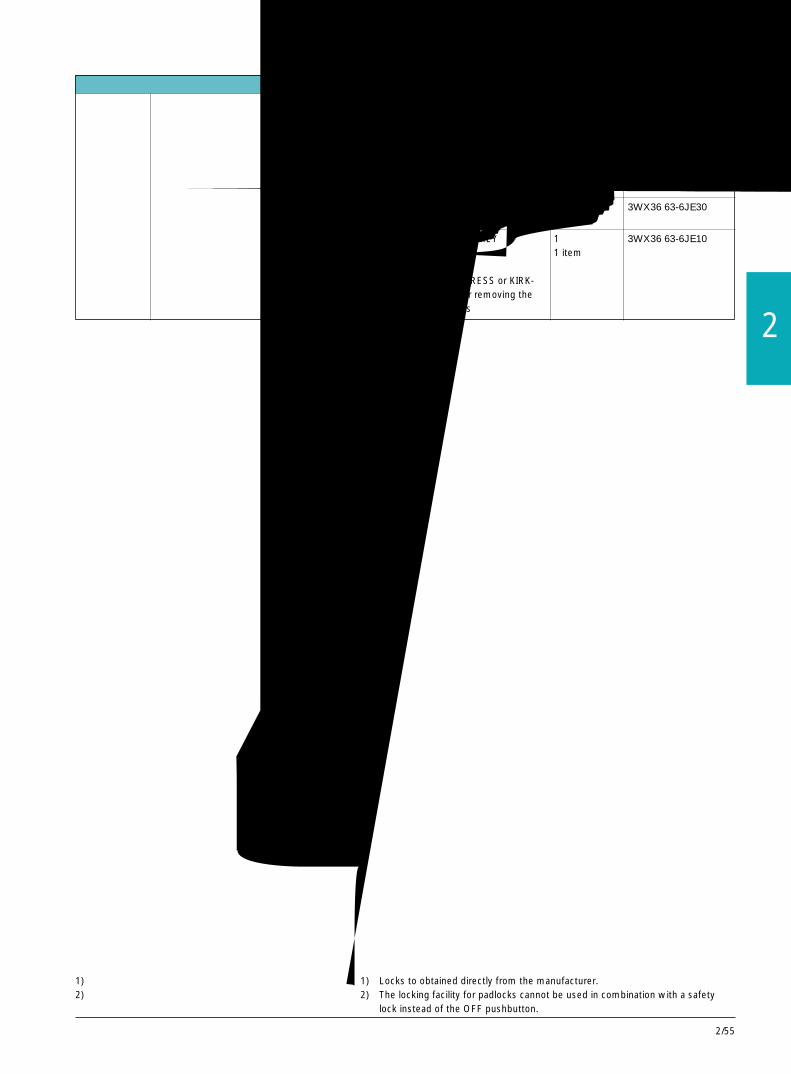
2/55
2
用于 CASTELL 锁或 FORTRESS 锁 1)的安装组件 1 套 3WX36 63-6JE00从生产厂家处获得的锁(FS2)或 FORTRESS 锁 1 item(H31LH/65º/标准)Mounting kit for CASTELL lock or FORTRESS lock1)
Locks to be obtained from the manufacturer:CASTELL Lock (FS2) or FORTRESS lock(H31LH/65º/Standard)
用于 KIRK-KEY 锁 1)的安装组件 1 套 3WX36 63-6JE30Mounting kit for KIRK-KEY lock1) 1 item
用于 CASTELL、FORTRESS 或 KIRK-KEY 锁 1) 1 套 3WX36 63-6JE10的锁定装置;当钥匙取出后,钥匙孔被盖住,最多 1 item可用 4 把挂锁锁住。Locking facility for CASTELL,FORTRESS or KIRK-KEY lock1); keyhole is covered after removing thekey, lockable with up to 4 padlocks
1) 锁可从锁具生产厂家直接获得。2) 用于挂锁的锁定装置不能与替代分闸按钮的安全锁组合。
1) Locks to obtained directly from the manufacturer.2) The locking facility for padlocks cannot be used in combination with a safety
lock instead of the OFF pushbutton.
用于改装的附件 Accessories for retrofits
3WN6断路器,3极和 4极,至 3200A3WN6 Circuit-Breakers, 3 and 4-pole, up to 3200A
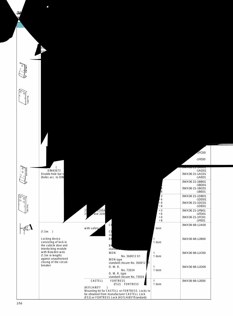
2/56
3WN6断路器,3极和 4极,至 3200A3WN6 Circuit-Breakers, 3 and 4-pole, up to 3200A用于改装的附件 Accessories for retrofits
描述 额定电流 In 尺寸等级 极数 每台断路器 每一套所需数量 订货号
Description Rated current In Size Number of poles Quant. required per per 1 setcircuit-breaker Order No.
用于固定式断路器 当改装断路器时,断路器侧面和铭牌上的订货号应按照安装说明相应更改。For fixed-mounted When retrofitting these parts the Order No. of the circuit-breaker on the nameplate on thecircuit-breakers control-panel and on the breaker side should be changed according to instructions.
主回路连接母排 至 1000 A I 3 极 1 套 =3 件 3WX36 21-1AB00前置,单孔,垂直 up to 1000 A 3-pole 1 set =3 itemsConnecting bars for main ter- 1 套 =6 件 -1AD00minals accessible from the front 1 set =6 itemssingle-hole bar, vertical 4 极 1 套 =4 件 3WX36 21-1AC00
4-pole 1 set =4 items1 套 =8 件 -1AE001 set =8 items
1250 和 1600 A I 3 极 1 套 =3 件 3WX36 21-1BB001250 and 1600 A 3-pole 1 set =3 items
1 套 =6 件 -1BD001 set =6 items
4 极 1 套 =4 件 3WX36 21-1BC004-pole 1 set =4 items
1 套 =8 件 -1BE001 set =8 items
2000 A II 3 极 1 套 =3 件 3WX36 21-1DB003-pole 1 set =3 items
1 套 =6 件 -1DD001 set =6 items
4 极 1 套 =4 件 3WX36 21-1DC004-pole 1 set =4 items
1 套 =8 件 -1DE001 set =8 items
2500 和 3200 A II 3 极 1 套 =3 件 3WX36 21-1FB002500 and 3200 A 3-pole 1 set =3 items
1 套 =6 件 -1FD001 set =6 items
4 极 1 套 =4 件 3WX36 21-1FC004-pole 1 set =4 items
1 套 =8 件 -1FE001 set =8 items
双孔,垂直(孔洞 至 1000A I 3 极 /3-pole 1 套 =3 件 3WX36 21-1AB01符合 DIN43673 标准) up to 1000A 1 套 =6 件 -1AD01Double-hole bar vertical 4 极 /4-pole 1 套 =4 件 3WX36 21-1AC01(holes acc. to DIN 43 673) 1 套 =8 件 -1AE01
1250A 和 1600A I 3 极 /3-pole 1 套 =3 件 3WX36 21-1BB011250A and 1600A 1 套 =6 件 -1BD01
4 极 /4-pole 1 套 =4 件 3WX36 21-1BC011 套 =8 件 -1BE01
2000A II 3 极 /3-pole 1 套 =3 件 3WX36 21-1DB011 套 =6 件 -1DD01
4 极 /4-pole 1 套 =4 件 3WX36 21-1DC011 套 =8 件 -1DE01
2500A 和 3200A II 3 极 /3-pole 1 套 =3 件 3WX36 21-1FB012500A and 3200A 1 套 =6 件 -1FD01
4 极 /4-pole 1 套 =4 件 3WX36 21-1FC011 套 =8 件 -1FE01
锁定装置 带安全锁 CES 型 1 套 3WX36 68-1JA00由柜门上的锁和带钢缆 with safety lock 标准闭锁 No. SSG 10 1 item(1.5m 长)的联锁模块组成 CES type防止未经许可合闸断路器 standard closure No. SSG 10
BKS 型 1 套 3WX36 68-1JB00标准闭锁 No. S1 1 itemBKS typestandard closure No. S1IKON 型 1 套 3WX36 68-1JC00标准闭锁 No. 360012 K1 1 itemIKON typestandard closure No. 360012 K1O. M. R.型 1 套 3WX36 68-1JD00标准闭锁 No. 73034 1 itemO. M. R. typestandard closure No. 73034
用于 CASTELL 锁或 FORTRESS 锁的安装组件 1 套 3WX36 68-1JE00从生产厂家处获得的锁(FS2)或 FORTRESS 锁 1 item(H31LH/65º/标准)Mounting kit for CASTELL or FORTRESS. Locks tobe obtained from manufacturer CASTELL Lock(FS2) or FORTRESS Lock (H31LH/65º/Standard)
Locking deviceconsisting of lock inthe cubicle door andinterlocking modulewith Bowden wire(1.5m in length)against unauthorizedclosing of the circuit-breaker

2/57
2
用于改装的附件 Accessories for retrofits辅助接线端子 / Auxiliary connector 1 件 3WX36 25-1JC00
1 item
锁定装置 当断路器合闸后防止打开柜门 /Against opening of 1 件 1 item 3WX36 67-2JA00Auxiliary connector the cubicle door when the circuit-breaker is closeed
当柜门打开时,防止断路器合闸 /Against closing 1 件 1 item 3WX36 67-1JA00the circuit-breaker when the cubicle door is open
消弧罩盖 1) 至 1600 A I 3 极 1 件 3WX36 14-0GA00Arc chute cover 1) up to 1600 A 3-pole 1 item
4 极 1 件 -0HA004-pole 1 item
2000~3200 A II 3 极 1 件 3WX36 14-0KA003-pole 1 item4 极 1 件 -0LA004-pole 1 item
用于导向框架 / For guide frames
消弧罩盖 1) 至 1600A I 3 极 1 件 3WX36 14-0GB00Arc chute cover 1) up to 1600A 3-pole 1 item
4 极 1 件 -0HB004-pole 1 item
2000~3200A II 3 极 1 件 3WX36 14-0KB003-pole 1 item4 极 1 件 -0LB004-pole 1 item
主回路连接母排前置 至 1000A I 3 极 1 套 =3 件 3WX36 23-1AB00up to 1000A 3-pole 1 set =3 items
4 极 1 套 =4 件 -1AC004-pole 1 set=4 items
1250 和 1600A I 3 极 1 套 =3 件 3WX36 23-1BB001250 and 1600A 3-pole 1 set =3 items
4 极 1 套 =4 件 -1BC004-pole 1 set=4 items
双孔,垂直(孔洞符合 DIN 至 1000A I 3 极 1 套 =3 件 3WX36 23-1AB0143673 标准) up to 1000A 3-pole 1 set =3 items
4 极 1 套 =4 件 -1AC014-pole 1 set=4 items
1250 和 1600A I 3 极 1 套 =3 件 3WX36 23-1BB011250 and 1600A 3-pole 1 set =3 items
4 极 1 套 =4 件 -1BC014-pole 1 set=4 items
主回路连接母排 至 1000A I 3 极 1 套 =3 件 3WX36 23-3AB00垂直后置 up to 1000A 3-pole 1 set =3 items
4 极 1 套 =4 件 -3AC004-pole 1 set=4 items
1250 和 1600A I 3 极 1 套 =3 件 3WX36 23-3BB001250 and 1600A 3-pole 1 set =3 items
4 极 1 套 =4 件 -3BC004-pole 1 set=4 items
1) 用于额定电压>415V时,防止飞弧,对于主回路母排垂直前置,不需要消弧罩盖。
单孔,垂直Connecting bars formain terminalsaccessible from thefrontSingle-hole bar vertical
Double-hole bar, vertical(holes acc.to DIN 43673)
Connecting bars formain terminalsat the rear, vertical
1) Required for protection against flash-over for voltages >415V. Notrequired for vertical main connections accessible from the front.
3WN6断路器,3极和 4极,至 3200A3WN6 Circuit-Breakers, 3 and 4-pole, up to 3200A

2/58
3WN6断路器,3极和 4极,至 3200A3WN6 Circuit-Breakers, 3 and 4-pole, up to 3200A用于改装的附件 Accessories for retrofits
描述 额定电流 In 尺寸等级 极数 每台断路器 每一套所需数量 订货号
Description Rated current In Size Number of Quant. required per per 1 setpoles circuit-breaker Order No.
用于导向框架 / For guide frames
主回路连接母排 至 2000A II 3 极 1 套 =3 件 3WX36 23-1DB00前置 up to 2000A 3-pole 1 set =3 items单孔,垂直 1 套 =6 件 -1DD00Connecting bars for main 1 set =6 itemsterminals accessible from the 4 极 1 套 =4 件 3WX36 23-1DC00front single-hole bar, vertical 4-pole 1 set =4 items
1 套 =8 件 -1DE001 set =8 items
2500 和 3200A II 3 极 1 套 =3 件 3WX36 23-1EB002500 and 3200A 3-pole 1 set =3 items
1 套 =6 件 -1ED001 set =6 items
4 极 1 套 =4 件 3WX36 23-1EC004-pole 1 set =4 items
1 套 =8 件 -1EE001 set =8 items
双孔,垂直(孔洞 2000A II 3 极 1 套 =3 件 3WX36 23-1DB01符合 DIN43 673 标准) 3-pole 1 set =3 itemsDouble-hole bar vertical 1 套 =6 件 -1DD01(holes acc. to DIN 43 673) 1 set =6 items
4 极 1 套 =4 件 3WX36 23-1DC014-pole 1 set =4 items
1 套 =8 件 -1DE011 set =8 items
2500 和 3200A I 3 极 1 套 =3 件 3WX36 23-1EB012500 and 3200A 3-pole 1 set =3 items
1 套 =6 件 -1ED011 set =6 items
4 极 1 套 =4 件 3WX36 23-1EC014-pole 1 set =4 items
1 套 =8 件 -1EE011 set =8 items
位置信号发送开关 运行位置 试验位置 退出位置 先决条件(由抽屉式断路器本体操作) Connected Test Disconnec- PreconditionPosition signalling switches position position ted position(actuated by draw-outcircuit-breaker) 1NO+1NC 1NO+1NC 1NO+1NC 如果位置开 1 套 =1 件 3WX36 84-1JA10
关还未安装, 1 set =1 items则可以采用possible if apositionswitch is notyet fitted
3NO+3NC 2NO+2NC 1NO+1NC 如果位置开 1 套 =1 件 3WX36 84-1JC10关还未安装, 1 set =1 items则可以采用possible if apositionswitch is notyet fitted
2NO+2NC 1NO+1NC - 如果导向框 1 套 =1 件 3WX36 84-1JB10架内每个位 1 set =1 items置已安装1NO + 1NC位置开关则可以采用possible if aposition switch1NO+1NC perposition is fittedin the guideframe
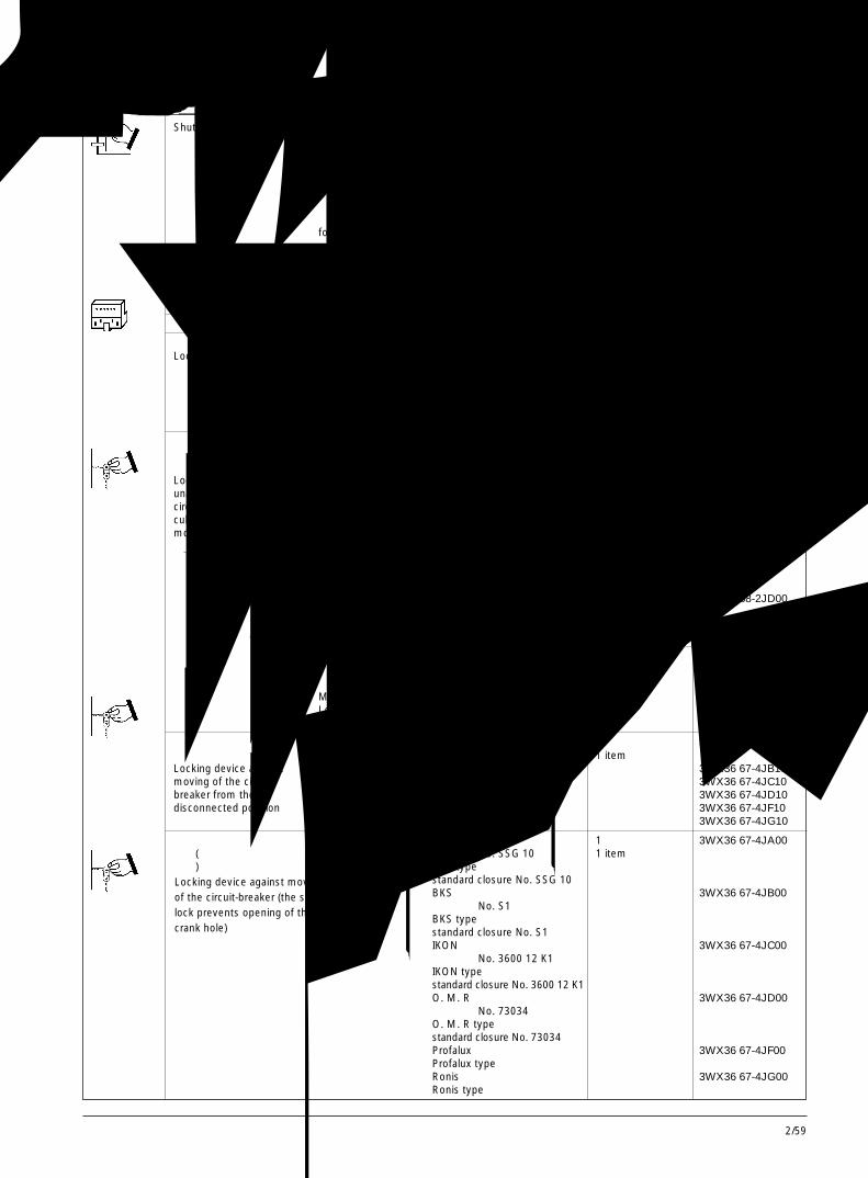
2/59
2
用于改装的附件 Accessories for retrofits安全挡板 防止接触到主回路Shutter Protection against touching the main connection
用于 3 极导向框架 用于额定电流for 3-pole guide frames for rated current
~1600 A 1 件 3WX36 84-3CA00
2000 A~3200 A 1 item -3DA00
用于 4 极导向框架 用于额定电流for 4-pole guide frames for rated current
~1600 A 1 件 3WX36 84-3CB00
2000 A~3200 A 1 item -3DB00
辅助接线端子块 用于导向框架-用作替换和改装 1 件 3WX36 27-1JA00Auxiliary draw-out connectors for guide frames-for replacement and retrofit 1 item
用于抽屉式断路器 / for draw-out circuit-breakers
锁定装置 当断路器在运行位置防止打开柜门 1 件 3WX36 67-1JC00Locking device against opening of the cubicle door with the 1 item
circuit-breaker in connected position当柜门打开时,防止断路器合闸(只在运行位置有效) -1JB00against closing with open door (only in connected position)当柜门打开时,防止移动断路器本体 -3JA00against moving with open door
锁定装置防止未经许可合 带安全锁 CES 型 1 套 3WX36 68-2JA00闸断路器(由柜门上的锁 with safety lock 标准闭锁 No. SSG 10 1 set和联锁模块组成) 锁具在运行位置有效 CES typeLocking device against Locking device standard closure No. SSG 10unauthorized closing of the effective in connected BKS 型 3WX36 68-2JB00circuit-breaker (lock in the position 标准闭锁 No. S1cubicle door and interlocking BKS typemodule) standard closure No. S1
IKON 型 3WX36 68-2JC00标准闭锁 No. 3600 12 K1IKON typestandard closure No. 3600 12 K1O.M.R.型 3WX36 68-2JD00标准闭锁 No. 73034O.M.R.typestandard closure No. 73034
用于 CASTELL 锁或 FORTRESS 锁的安装组件 1 套 3WX36 68-2JE00从生产厂家处获得的锁CASTELL 锁(FS2) 1 set或 FORTRESS 锁(H31LH/AC65º/ 标准)Mounting kit for CASTELL lock or FORTRESS lockLocks to be procured from the manufacturer: CASTELLLock (FS2) or FORTRESS lock (H31LH/AC65º/Standard)
锁定装置防止在退出位置 带安全锁 CES 型 CES type 1 件 3WX36 67-4JA10移动断路器本体 with safety lock 1 itemLocking device against BKS 型 BKS type 3WX36 67-4JB10moving of the circuit- IKON 型 IKON type 3WX36 67-4JC10breaker from the O. M. R 型 O. M. R type 3WX36 67-4JD10disconnected position Profalux 型 Profalux type 3WX36 67-4JF10
Ronis 型 Ronis type 3WX36 67-4JG10
锁定装置防止移动断路器 带安全锁 CES 型 1 件 3WX36 67-4JA00本体(安全锁防止打开曲 with safety lock 标准闭锁 No. SSG 10 1 item柄孔) CES type
standard closure No. SSG 10BKS 型 3WX36 67-4JB00标准闭锁 No. S1BKS typestandard closure No. S1IKON 型 3WX36 67-4JC00标准闭锁 No. 3600 12 K1IKON typestandard closure No. 3600 12 K1O. M. R 型 3WX36 67-4JD00标准闭锁 No. 73034O. M. R typestandard closure No. 73034Profalux 型 3WX36 67-4JF00Profalux typeRonis 型 3WX36 67-4JG00Ronis type
Locking device against movingof the circuit-breaker (the sefetylock prevents opening of thecrank hole)
3WN6断路器,3极和 4极,至 3200A3WN6 Circuit-Breakers, 3 and 4-pole, up to 3200A

2/60
备件 Spare parts描述 适用的断路器型号 额定电流 尺寸等级 极数 每台断路器 每一套或一件
所需数量 订货号Description For circuit-breaker Rated current Size Number of Quant. required per per 1 set or 1 item
Type poles circuit-breaker Order No.
用于固定式和抽屉式断路器 / For fixed-mounted and draw-out circuit-breakers
主触头组 3WN6 0.1 to 3WN6 2.1 ~1000 A I 3 极 3 套 3WY36 21-0AA00Main contact 3-pole 3 setsset 3WN6 0.1-.....-....-Z K03 ~1000 A I 3 极 3 套 3WY36 21-0AA10
to 3-pole 3 sets3WN6 2.1-.....-....-Z K03
3WN6 0.3 to 3WN6 2.3 ~1000 A I 4 极 4 套 3WY36 21-0AA004-pole 4 sets
3WN6 0.3-.....-....-Z K03 ~1000 A I 4 极 4 套 3WY36 21-0AA10to 4-pole 4 sets3WN6 2.3-.....-....-Z K03
3WN6 3.1 to 3WN6 4.1 1250 I 3极 3 套 3WY36 21-0BA00and 1600 A 3-pole 3 sets
3WN6 3.3 to 3WN6 4.3 1250 I 4极 4 套 3WY36 21-0BA00and 1600 A 4-pole 4 sets
3WN6 5.1 2000A II 3 极 3 套 3WY36 21-0DA003-pole 3 sets
3WN6 5.3 2000A II 4 极 4 套 -0DA004-pole 4 sets
3WN6 6.1 2500A II 3 极 3 套 3WY36 21-0EA003-pole 3 sets
3WN6 6.3 2500A II 4 极 4 套 -0EA004-pole 4 sets
3WN6 7.1 3200A II 3 极 3 套 3WY36 21-0FA003-pole 3 sets
3WN6 7.3 3200A II 4 极 4 套 -0FA004-pole 4 sets
灭弧室 3WN6 0.1 to 3WN6 4.1 ~1600A I 3 极 3 件 3WY36 11-0CA00Arc chute 3-pole 3 items
3WN6 0.3 to 3WN6 4.3 ~1600A I 4 极 4 件 -0CA004-pole 4 items
3WN6 5.1 to 3WN6 7.1 2000A II 3 极 3 件 3WY36 11-0FA00~3200A 3-pole 3 items
3WN6 5.3 to 3WN6 7.3 2000A II 4 极 4 件 -0FA00~3200A 4-pole 4 items
曲柄 用于抽屉式断路器 1 件 3WX36 84--0JA00Crank for draw-out circuit-breaker 1 item
图 29 主触头组Fig. 2/29 Main contact set
3WN6断路器,3极和 4极,至 3200A3WN6 Circuit-Breakers, 3 and 4-pole, up to 3200A
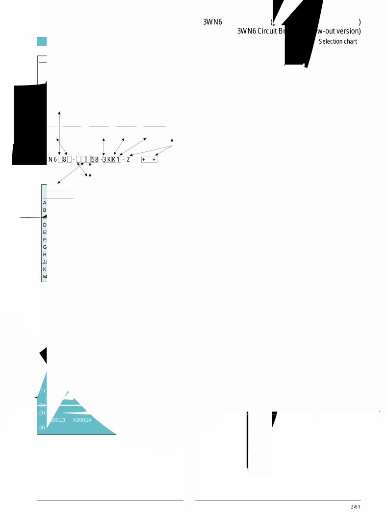
2/61
2
重要说明:
1. 上述型号为抽屉式断路器。固定式断路器参照样本。对于抽屉式断路器,
如需其他方式的主回路连接方式,则可在断路器订货号的最后加 -Z,标
上相应规格代码。
2. 储能电机的其他电压等级及其代码举例 -51: DC24V; 54: DC45V; 56:
AC110V。如需其他电压等级,请参照有关样本。
3.欠压线圈其他电压等级及其代码举例 - 3B: DC24V; 3E: DC30V; 3F: DC48V;
3G: DC60V; 3H: AC110V; 3M: AC380V。
如需可延时 (0.2~3.2s) 欠压线圈,则其电压等级和代码如下 - 4H: AC110V;
4K: AC220V; 4M: AC380V。
4. 分励线圈其他电压等级及其代码举例 - B: DC24V; F: DC48V; G: DC56V;
H: AC110V/DC110V; K: AC220V/DC220V。
如需两个分励线圈,则可用如下代码取代原欠压线圈代码 - 1B: DC24V;
1F: DC48V; 1H: AC110V/DC110V; 1K: AC220V/DC220V。
5. 辅助触头其他型式代码 - 3: 2NO+2NC+2CO。
6. 过电流脱扣器 1D~1P 如需增加附加功能 1,则脱扣器代码应相应改为
3D~3P ;过电流脱扣器 1D~1P 如需增加附加功能 2,则脱扣器代码应
相应改为 7D~7P。如需使断路器具有通讯功能,则应选 7D~7P 相应的
脱扣器,并增加通讯模式 Z=F01 或 F05,详细描述请参见有关样本。
7. 如需其他规格,例如:计数器、钥匙锁、电动机开关、机械联锁、各种
锁定装置、位置信号发送开关等附件,则可在断路器订货号的最后加 -Z,
标上相应规格代码,例如需三锁两钥匙,则完整断路器的型号为
3WN6……-……-Z S01,详细描述请参见有关样本。
8. 用于对 N 导线进行保护或需要接地故障保护的 3 极断路器,或采用 E 型
或 J 型脱扣器的4 极断路器用于 N 导线保护或接地故障保护,均应另外
订购用于 N 导线的电流互感器,详细订货号请参见有关样本。
9. 柜门密封框、过电流脱扣器功能测试仪等辅助装置的订货号请参见有关
样本。
订货号示例:3WN6281-3FD58-4KK3-Z R20+C01+R07+R30 该订货号表
明:三极抽屉式断路器,框架电流 1000A,整定电流范围 400~1000A,带
3D 型脱扣器 (三段保护+中线保护,带液晶显示,具有附加功能 1),电操
机构为 AC220V,欠压线圈带延时 AC220V,分励线圈 AC220V,带辅助
2NO+2NC+2CO 辅助触头; 导向框架装有安全挡板,断路器面板带计数
器,主回路连接垂直后置,断路器合闸时开关柜门不能打开。
框架电流代号:
0: In = 630A
1: In = 800A
2: In = 1000A
3: In = 1250A
4: In = 1600A
{框架尺寸
等级 Ⅰ
框架尺寸
等级 Ⅱ
5: In = 2000A
6: In = 2500A
7: In = 3200A
极数代号:
1: 3 极
3: 4 极
{储能电机代号
58: AC220V 其他
电压等级见下页
欠压线圈代号
3K: AC220V 其他
电压等级见下页
分励线圈代号
K: AC220V 其他
电压等级见下页
辅助触头代号 1:
2NO + 2NC
其他辅助触头下页
如需附加规格,
则加 -z 表示,并
标相应的代码
脱扣器电流 Ir 的
整定范围代号:
A: 126~315A
B: 160~400A
C: 200~500A
D: 252~630A
E: 320~800A
F: 400~1000A
G: 500~1250A
H: 640~1600A
J: 800~2000A
K: 1000~2500A
M: 1280~3200A
微处理器控制电子式过电流脱扣器代号:
0 V: 二段保护 - 短路短延时 + 短路瞬时
0 B: 三段保护 - 过载长延时、短路短延时、短路
瞬时
0 C: 三段保护 + 中线保护 + 接地故障保护 - 只用
于 3 极断路器
0 G: 三段保护 + 中线保护 + 接地故障保护 - 只
用于 4 极断路器
1 D: 三段保护 + 中线保护 ,带电流液晶显示
1 E: 三段保护 + 中线保护 + 接地故障保护,带
电流液晶显示
1 F: 三段保护 + 中线保护 + 接地故障保护,带
电流液晶显示 - 只用于 4 极断路器
1 H: 三段保护 + 中线保护,可编程输入整定值
1 J: 三段保护 + 中线保护 + 接地故障保护,可
编程输入整定值
1 K: 三段保护 + 中线保护 + 接地故障保护,可
编程输入整定值 - 只用于 4 极断路器
1 N: 三段保护 + 中线保护 ,带电流液晶显示,
菜单式编程输入整定值
1 P: 三段保护 + 中线保护 + 接地故障保护,带
电流液晶显示,菜单式编程输入整定值
说明
断路器供货时均提供如下基本配置而不必另加说明:
(1) 电子式过电流脱扣器本体均带有脱扣原因 LED 显示,断路器运行状
态 LED 显示,查询和自诊断按键。
(2) 脱扣信号发送触头 S11 (在接线端子 X200.12 和 X200.13 之间) 。
(3) 合闸准备就绪显示器,合闸准备就绪信号发送触头 S7 (在接线端子
X200.13 和 X200.14 之间) 。
(4) 机械重合闸锁定;主回路连接水平后置。
3WN6 8 - 58 -3KK1 - Z + +
快速选型表 Selection chart
3WN6 万能式断路器(抽屉式断路器的常用规格)3WN6 Circuit Breaker (Draw-out version)
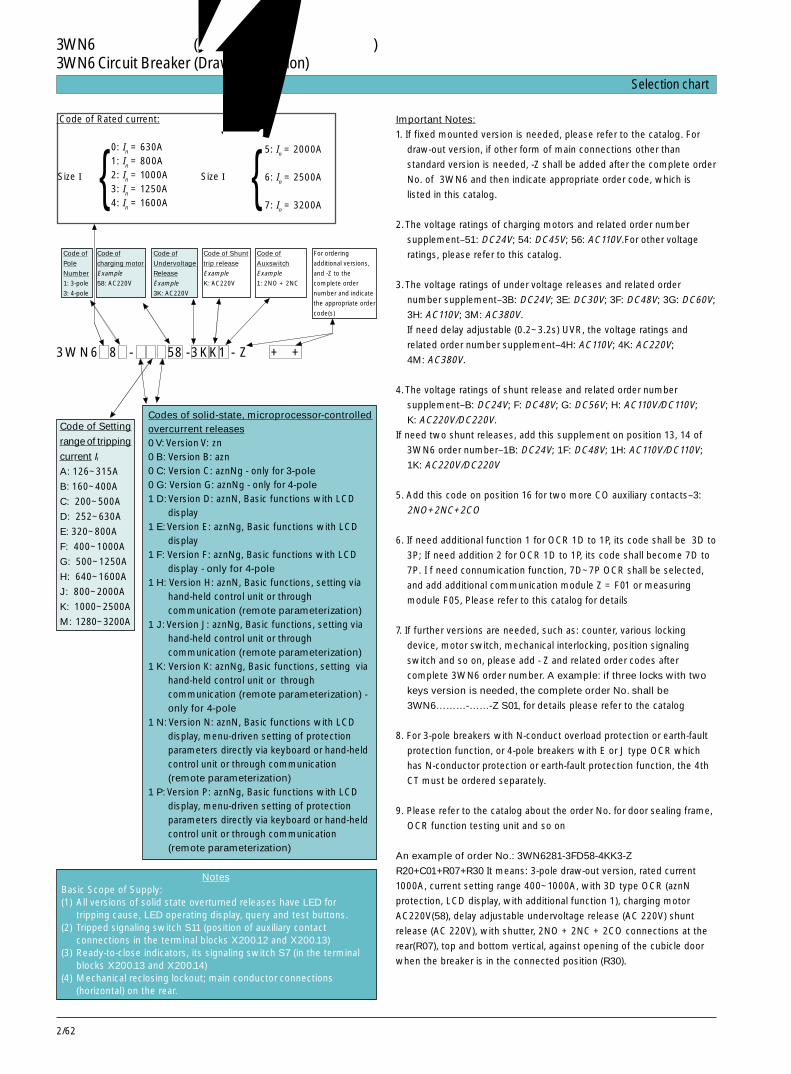
2/62
Important Notes:
1. If fixed mounted version is needed, please refer to the catalog. For
draw-out version, if other form of main connections other than
standard version is needed, -Z shall be added after the complete order
No. of 3WN6 and then indicate appropriate order code, which is
listed in this catalog.
2. The voltage ratings of charging motors and related order number
supplement–51: DC24V; 54: DC45V; 56: AC110V.For other voltage
ratings, please refer to this catalog.
3. The voltage ratings of under voltage releases and related order
number supplement–3B: DC24V; 3E: DC30V; 3F: DC48V; 3G: DC60V;
3H: AC110V; 3M: AC380V.
If need delay adjustable (0.2~3.2s) UVR, the voltage ratings and
related order number supplement–4H: AC110V; 4K: AC220V;
4M: AC380V.
4. The voltage ratings of shunt release and related order number
supplement–B: DC24V; F: DC48V; G: DC56V; H: AC110V/DC110V;
K: AC220V/DC220V.
If need two shunt releases, add this supplement on position 13, 14 of
3WN6 order number–1B: DC24V; 1F: DC48V; 1H: AC110V/DC110V;
1K: AC220V/DC220V
5. Add this code on position 16 for two more CO auxiliary contacts–3:
2NO+2NC+2CO
6. If need additional function 1 for OCR 1D to 1P, its code shall be 3D to
3P; If need addition 2 for OCR 1D to 1P, its code shall become 7D to
7P. I f need connumication function, 7D~7P OCR shall be selected,
and add additional communication module Z = F01 or measuring
module F05, Please refer to this catalog for details
7. If further versions are needed, such as: counter, various locking
device, motor switch, mechanical interlocking, position signaling
switch and so on, please add - Z and related order codes after
complete 3WN6 order number. A example: if three locks with two
keys version is needed, the complete order No. shall be
3WN6………-……-Z S01, for details please refer to the catalog
8. For 3-pole breakers with N-conduct overload protection or earth-fault
protection function, or 4-pole breakers with E or J type OCR which
has N-conductor protection or earth-fault protection function, the 4th
CT must be ordered separately.
9. Please refer to the catalog about the order No. for door sealing frame,
OCR function testing unit and so on
An example of order No.: 3WN6281-3FD58-4KK3-Z
R20+C01+R07+R30 It means: 3-pole draw-out version, rated current
1000A, current setting range 400~1000A, with 3D type OCR (aznN
protection, LCD display, with additional function 1), charging motor
AC220V(58), delay adjustable undervoltage release (AC 220V) shunt
release (AC 220V), with shutter, 2NO + 2NC + 2CO connections at the
rear(R07), top and bottom vertical, against opening of the cubicle door
when the breaker is in the connected position (R30).
Code of Rated current:
0: In = 630A1: In = 800A2: In = 1000A3: In = 1250A4: In = 1600A
{Size I Size I Ⅱ
5: In = 2000A
6: In = 2500A
7: In = 3200A
Code of
Pole
Number
1: 3-pole
3: 4-pole
{Code of
charging motor
Example
58: AC220V
Code of
Undervoltage
Release
Example
3K: AC220V
Code of Shunt
trip release
Example
K: AC220V
Code of
Auxswitch
Example
1: 2NO + 2NC
For ordering
additional versions,
and -Z to the
complete order
number and indicate
the appropriate order
code(s)
Code of Setting
range of tripping
current IrA: 126~315A
B: 160~400A
C: 200~500A
D: 252~630A
E: 320~800A
F: 400~1000A
G: 500~1250A
H: 640~1600A
J: 800~2000A
K: 1000~2500A
M: 1280~3200A
Codes of solid-state, microprocessor-controlledovercurrent releases0 V: Version V: zn0 B: Version B: azn0 C: Version C: aznNg - only for 3-pole0 G: Version G: aznNg - only for 4-pole1 D: Version D: aznN, Basic functions with LCD
display1 E: Version E: aznNg, Basic functions with LCD
display1 F: Version F: aznNg, Basic functions with LCD
display - only for 4-pole1 H: Version H: aznN, Basic functions, setting via
hand-held control unit or throughcommunication (remote parameterization)
1 J: Version J: aznNg, Basic functions, setting viahand-held control unit or throughcommunication (remote parameterization)
1 K: Version K: aznNg, Basic functions, setting viahand-held control unit or throughcommunication (remote parameterization) -only for 4-pole
1 N: Version N: aznN, Basic functions with LCDdisplay, menu-driven setting of protectionparameters directly via keyboard or hand-heldcontrol unit or through communication(remote parameterization)
1 P: Version P: aznNg, Basic functions with LCDdisplay, menu-driven setting of protectionparameters directly via keyboard or hand-heldcontrol unit or through communication(remote parameterization)
NotesBasic Scope of Supply:(1) All versions of solid state overturned releases have LED for
tripping cause, LED operating display, query and test buttons.(2) Tripped signaling switch S11 (position of auxiliary contact
connections in the terminal blocks X200.12 and X200.13)(3) Ready-to-close indicators, its signaling switch S7 (in the terminal
blocks X200.13 and X200.14)(4) Mechanical reclosing lockout; main conductor connections
(horizontal) on the rear.
3WN6 8 - 58 -3KK1 - Z + +
快速选型表 Selection chart
3WN6 万能式断路器(抽屉式断路器的常用规格)3WN6 Circuit Breaker (Draw-out version)

2/63
2
技术数据 Technical data尺寸等级 I IISize
型号Type 3WN6 0 3WN6 1 3WN6 2 3WN6 3 3WN6 4 3WN6 5 3WN6 6 3WN6 7
额定电流In (55ºC, 50/60Hz) 主回路Rated current In at 55ºC, 50/60Hz Main conductors A 630 800 1000 1250 1600 2000 2500 3200
N 导线回路(只对于四极)N conductors (4-pole only) A 630 800 1000 1250 1600 2000 2500 3200
额定工作电压 Ue (50/60Hz)Rated operational voltage Ue at 50/60Hz AC V up to 690
额定冲击耐受电压 Uimp 主回路Rated impulse withstand voltage Main conducting path7) kV 8Uimp 辅助回路
Auxiliary circuits kV 4
使用类别Utilization category B
额定短路接通能力Icm(峰值)Rated short-circuit making up to AC 415V kA 143 176capacity up to AC 500V kA 143 176(peak value) Icm up to AC 690V kA 110 110
额定运行短路分断能力Ics(有效值)Rated service short-circuit up to AC 415V kA 65 80breaking capacity up to AC 500V kA 65 80(rms value) Ics up to AC 690V kA 50 50
额定极限短路分断能力 Icu(有效值)Rated ultimate short-circuit up to AC 415V kA 65 80breaking capacity Icu up to AC 500V kA 65 80(rms value) up to AC 690V kA 50 50
允许环境温度 工作Permissible ambient Operation ºC -20...+70temperature 储存
Storage ºC -40...+80
额定短时耐受电流Icw (50/60Hz) 0.5s kA 50 50 65Rated short-time 1s kA 35/501) 50 65withstand current Icw 2s kA 25/301) 30 60at 50/60Hz 3s kA 20/251) 25 50
柜内温度为以下值时,固定安装式与抽屉式断路器的允许负载permissible Loading of fixed- up to 55ºC A 630 800 1000 1250 1600 2000 2500 3200mounted and draw-out at 60ºC A 630 800 1000 1250 1550 2000 2270 3050circuit-breakers with internal at 70ºC A 630 800 1000 1250 1450 2000 2030 2850cubicle temperature2)3)4)
滑环电动机转子额定工作电压 Uer
Rotor rated operational voltage Uer V 2000
在三相平衡负载(没有导体排和 固定安装式断路器金属元件)下对应于In的功率损耗 Fixed-mounted W 40 60 90 90 140 170 260 420Power loss at In with 3-phase circuit-breakersbalanced load (without conductorbars and metal components)2)4) 抽屉式断路器
(包括导向框架)Draw-out circuit- W 80 130 205 205 310 310 510 760breakers incl. guide frame
寿命Endurance有维修 机械寿命 操作次数 20 000 20 000with maintenance5) mechanical/ Operating
电气寿命 Cycles 20 000 20 000electrical6)
无维修 机械寿命 操作次数 10 000 10 000without maintenance5) mechanical/ Operating
电气寿命 Cycles 6 000 2 000electrical6)
操作频率Switching frequency 1/min 1
从过电流脱扣器使断路器发生脱扣到发出下个合闸指令之间的最小时间间隔(只对于重合闸闭锁具有自动机械复位而言)Minimum interval between circuit-breaker tripping by over- ms 80current release and the next closing command (only withautomatic mechanical reset of the closing lockout)
3WN6断路器,3极和 4极,至 3200A3WN6 Circuit-Breakers, 3 and 4-pole, up to 3200A
2/64
3WN6断路器,3极和 4极,至 3200A3WN6 Circuit-Breakers, 3 and 4-pole, up to 3200A技术数据 Technical data尺寸等级 I IISize型号Type 3WN60 3WN61 3WN62 3WN63 3WN64 3WN65 3WN66 3WN67安装位置Mounting position
防护等级 安装于柜内和框架内的断路器:IP 20Degree of protection 控制面板上带有密封框:IP 54
Circuit-breaker: IP 20, for cubicle or frame mounting;control panel with sealing frame: IP 54
主回路导体的最小截面 铜排 裸露Min. cross-sections Copper bars, bare Qty 1× 1 × 2 × 2 × 2 × 2 × 3 × 3 ×of main conductors mm2 50×10 60×10 40×10 50×10 60×10 100×10 100×10 100×10
铜排 涂黑Copper bars, painted black Qty 1 × 1 × 1 × 2 × 2 × 2 × 2 × 3 ×
mm2 40 × 10 50 × 10 60 × 10 40 × 10 50 × 10 80 × 10 100×10 100×10
辅助回路连接导线(铜) 辅助导体的 实心线、 1 × 0.5...2.5mm2; 1 × AWG14Auxiliary connecting 最大数目× solid and 2 × 1.0mm2
leads 截面积 带端子的细绞线(copper) Max. number of finely stranded with
aux. conn.leads end sleevesx cross-section
重量 三极断 固定安装式 约 kg 34 34 34 36 36 57 59 61Weights 路器 Fixed- approx.kg
3-pole circuit- mountedbreakers circuit-breaker
抽屉式 约 kg 36 36 36 38 38 59 61 63Draw-out approx.kgcircuit-breaker
导向框架 约 kg 22 22 22 23 23 35 37 37Guide frame approx. kg
四极断 固定安装式 约 kg 47 47 47 49 49 70 72 74路器 Fixed- approx. kg4-pole circuit- mountedbreakers circuit-breaker
抽屉式 约 kg 49 49 49 51 51 72 74 76Draw-out approx. kgcircuit-breaker
导向框架 约 kg 27 27 27 28 28 46 48 48Guide frame approx.kg
1) 断路器订货号后有 -Z 和订货码 K03 时,此值有效,详见第 2/40 页。Values are for circuit-breakers with -Z and order code K03, see “further versions” on page 2/40.
2) 固定安装式为主回路水平连接,抽屉式为主回路垂直连接。Horizontal connection with fixed-mounted version, vertical connection with draw-out version.
3) 指断路器上方约 1/3 处的空间温度。The temperatures refer to the air space around the upper one-third of the circuit-breaker.
4) 根据环境温度,以 50/60Hz 时正弦电流为基准。谐波和更高的频率将导致热量与损耗上升。According to the ambient temperature, with sinusoidal current at 50/60Hz. Heating and losses will rise due to harmonics and higher frequencies.
5) 维修:更换触头组。Maintenance: exchange of the contact set.
6) 每组触头。在 cosϕ=0.8 时分断额定电流In。Per set of contacts. Breaking the rated current In with p.f.=0.8.
7) 额定绝缘电压 Ui=AC 1000V。Rated insulation voltage Ui=AC 1000V.
and/or
2/65
2
操作机构Operating mechanisms
手动储能、机械合闸式操作机构Manual operating mechanism with stored-energy feature with mechanical closing
合闸/储能机构 扳动手柄所需的最大操作力 N 210Closing/charging Max. operating force required to move the handlestored-energy 储能所需的手柄扳动次数 5mechanism Number of handle strokes required for charging
手动储能、机械与电气合闸式操作机构Manual operating mechanism with stored-energy feature with mechanical and electrical closing
给储能机构储能 参见“手动储能、机械合闸式操作机构”Charging stored- See “Manual operating mechanism withenergy mechanism stored-energy feature with mechanical closing”
合闸线圈 线圈电压工作范围Closing solenoid (Y1) Coil voltage tolerance 0.7 to 1.1 × Us
电池操作的电压范围 1)extended tolerance for battery operation1) at DC 24V, DC48V, 0.7 to 1.26 × Us
DC 60V, DC110V,DC220V
功率消耗Power consumption AC/DC VA/W 15
电压为Us 时,施加在合闸线圈上的指令的最小持续时间Min. command duration at Us for the closing solenoid ms 60
电压为Us 时的总合闸时间 (从对合闸线圈开始施加指令信号的一瞬间算起,适用于同步操作)Total closing time at Us after start of the command signal ms 80for the closing solenoid, suitable for synchronizing tasks
短路保护 1A TDz(时滞/time-lag)/1A至少需要 DIAZED 熔断器 (等级 gL) /具有 C 特性的小型断路器Short-circuit protectionsmallest permissible DIAZED fuse (Class gL)/m.c.b. with C characteristics
手动/电动机储能、机械与电气合闸式操作机构Manual/motorized operating mechanism with stored-energy feature with mechanical and electrical closing
手动操作机构 参见“手动储能、机械与电气合闸式操作机构”Manual operating mechanism See “Manual operating mechanism with stored-
energy feature with mechanical and electrical closing”
电动机 线圈电压工作范围 0.7 to 1.1 × Us
Motor Coil voltage tolerance电池操作的电压范围 1)extended tolerance for battery operation1) at DC 24V, DC48V, 0.7 to 1.26 × Us
DC 60V, DC110V,DC220V
电动机的功率消耗Power consumption of the motor AC/DC VA/W 40
电压为 100%Us 时给储能机构储能所需的时间 s 20Time required for charging the stored-energymechanism at 100%Us
合闸线圈 参见“手动储能、机械与电气合闸式操作机构”Closing solenoid See “Manual operating mechanism with stored-
energy feature with mechanical and electricalclosing”
短路保护电动机与合闸线圈具有相同额定控制电压Short-circuit protectionMotor and closing solenoid for equal rated control supply voltage
对于电动机和 至少需要 DIAZED 熔断器合闸线圈 (等级 gL)/具有C 特性的For motor and 小型断路器closing solenoid smallest permissible DIAZED fuse (Class gL)/ at Us=24V 2 A TDz (时滞/time lag) /2A
m.c.b. with C characteristics at Us=110-127V 1A TDz (时滞/time lag) /1Aat Us=220-250V 1A TDz (时滞/time lag) /1A
技术数据 Technical data
3WN6断路器,3极和 4极,至 3200A3WN6 Circuit-Breakers, 3 and 4-pole, up to 3200A

2/66
技术数据 Technical data
辅助脱扣器Auxiliary releases
分励脱扣器 可持续通电 操作值 吸合 (断路器脱扣)Shunt releases”f” (100% 接通), Operating values pick up ≥ 0.7 ×Us (circuit-breaker trips)(F1, F2) 适用于微动保 线圈电压工作范围
险锁定 Coil voltage tolerance 0.7 to 1.1 × Us
For continuouscommand (100%ON) suitable for 电池操作时的电压范围 at DC24V, DC 30V, 0.7 to 1.26 × Us
jog-safe blocking extended tolerance for DC48V, DC 60V,(fd) battery operation 1) DC 110V, DC 220V
额定控制电压 Us
Rated control supply voltage Us AC 50/60Hz V 110-127, 220-240DC V 24, 48, 60, 110-125, 220-250
功率消耗Power consumption AC/DC VA/W 15
电压为Us 时最小指令持续时间Min.command duration at Us ms 60
电压为 100%Us 时断路器分闸时间Break-time of the circuit-breaker at AC/DC ms ≤ 80at 100% Us
短路保护 1A TDz (时滞/time-lag) /1A至少需要 DIAZE熔断器 (等级 gL)/具有 C 特性的小型断路器Short-circuit protectionsmallest permissible DIAZED fuse (Class gL)/m.c.b. with C characteristics
额定控制电压 Us
Rated control supply AC 50/60 Hz V 110-127, 220-240voltage Us DC V 110-125, 220-250
线圈电压工作范围Coil voltage tolerance 0.85 to 1.1 × Us
功率消耗Power consumption AC/DC VA/W 1
电压为 Us 时的存储时间 2)/重储能时间 3)Storage time 2)at Us/recharging time3) at Us max. 5min/min.5 s
断路器分闸时间,短路保护 参见上面的“可持续通电”Break-time of the circuit-breaker, See “For continuous command” (above)short-circuit protection
1) 此线圈电压容限只在所示额定电压下适用,并且与电池电压相对应。
2) 存储时间=辅助电压消失后,由分励脱扣器执行的安全脱扣仍能实现的最长时间。
3) 重储能时间=分励脱扣器脱扣后,重新给储能装置储能所需的最短时间
1) The coil voltage tolerance is only applicable for the rated voltages indicated andcorresponds to the battery voltage.
2) Storage time=maximum time after failure of the auxiliary power supply for whichsafe tripping by the shunt release is still assured.Thereby it is assumed that the stored-energy mechanism was fully charged.
3) Recharging time=minimum time for recharging the stored-energy mechanism aftertripping by the shunt release.
3WN6断路器,3极和 4极,至 3200A3WN6 Circuit-Breakers, 3 and 4-pole, up to 3200A
具有储能特性由 f 脱扣器与3WX3156-1J.01型储能装置组成With stored-energy featureconsisting of "f" release and3WX31 56-1J.01storage device
2/67
2
操作值 吸合 (断路器合闸准备就绪)Operating values pickup ≥ 0.85 × Us (circuit-breaker can be closed)
释放 (断路器脱扣)dropout (0.35-0.7)× Us (circuit-breaker trips)
线圈电压工作范围 0.85-1.1 × Us
Coil voltage tolerance电池操作时的电压范围 at DC24V, DC 30V, DC 48V, 0.7-1.26 × Us
extended tolerance for battery DC 60V, DC 110V,operation1) DC 220V
额定控制电源电压 Us AC 50/60Hz V 110~127, 220~240, 380~415Rated control supply voltage Us DC V 24, 48, 60, 110~125, 220~250
功率消耗 AC VA 15Power consumption DC W 15
Us=0 时断路器的分闸时间Break-time of the circuit-breaker at Us=0
“r” 型(F3)Version “r” (F3)无延时 ms ≤ 100Without delay延时 100 ms ms ≤ 200with 100 ms delay“rc” 型(F8)有延时 s 0.2~3.2Version“rc”(F8)With delay, td=0.2~3.2 s
通过附加的常闭触头来直接分闸 ms ≤ 100Reset with additional NC contact for direct opening
短路保护至少需要 DIAZED 熔断器(等级 gL)/具有 C 特性的小型断路器Short-circuit protection 1 A TDZ(时滞/time-lag)/1Asmallest permissible DIAZED fuse (Class gL)/m.c.b. with C characteristics
辅助脱扣器Auxiliary releases
欠电压脱扣器”r” (F3)与 ”rc” (F8)Undervoltage releases”r”(F3) and”rc”(F8)
技术数据 Technical data
辅助触头(S1, S2, S3, S4)Contact-position driven auxiliary contacts (S1, S2, S3, S4)
额定绝缘电压Ui
Rated insulation voltage Ui AC/DC V 400 (415)
额定工作电压 Ue
Rated operational voltage Ue AC/DC V 400 (415)
额定工作电压 Ue V up to 240 400 (415)Rated operational voltage Ue
额定工作电流 Ie/AC-12 A 10 10Rated operational current Ie/AC-15 A 4 3
额定工作电压 Ue V 24 48 110 220Rated operational voltage Ue
额定工作电流 Ie/DC-12 A 10 8 3.5 1Rated operational current Ie/DC-13 A 8 4 1.2 0.4
最大允许 DIAZED熔断器 (等级 gL) 10A TDz (时滞/time-lag)Largest permissible DIAZED fuse (Class gL)最大允许具有 C 特性的小型断路器 10ALargest permissible m.c.b. with C characteristics
3WN6断路器,3极和 4极,至 3200A3WN6 Circuit-Breakers, 3 and 4-pole, up to 3200A
通断能力 AC 50/60 HzSwitching capacity
DC
短路保护 2)Short-circuit protection 2)

2/68
合闸准备就绪信号发送触头(S7)与脱扣信号发送触头(S11),符合DIN VDE 0630标准Ready-to-close signalling contact (S7) and tripped signalling contact (S11), acc. to DIN VDE 0630
通断能力 AC 50/60Hz 额定工作电压 Ue V 110 220Switching capacity Rated operational voltage Ue
额定工作电流Ie A 0.14 0.1Rated operational current Ie
DC 额定工作电压 Ue V 24 220Rated operational voltage Ue
额定工作电流Ie A 0.2 0.1Rated operational current Ie
短路保护2) 最大允许 DIAZED熔断器(等级 gL) 2A Dz(快速响应)Short-circuit protection2) Largest permissible DIAZED fuse (Class gL) 2A Dz (quick-response)
脱扣信号发送触头(S11) 脱扣后信号持续输出 复位以前持续Tripped-signalling contact (S11) Signalling duration after tripping continuous, till reset
过电流脱扣器的信号发送Signalling of the overcurrent release
过电流脱扣器通过光耦进 µP 故障、θ报警、”a” 脱扣先导信号发送、行信号发送 ”g” 报警、短时分级控制(ZSS)、负载监控Signalling of the overcurrent 过电流脱扣器被激活后借助于光耦进行无触点release via optocoupler 信号发送
µP fault, θ alarm, “a” leading tripped signalling, “g” alarm,short-time grading control (ZSS), load monitoring.Contactless signalling via opto-couplerafter activation of the overcurrent release.最大额定工作电压 Ue DC V 24Max.rated operational voltage Ue
最大额定工作电流Ie DC mA 20Max.rated operational current Ie
过电流脱扣器的测量精度 /Measuring accuracy of overcurrent release 保护功能符合 EN60947 标准;电流显示和通讯功能(F01): ± 5%;测量功能:(F05): ± 3%Protection functions acc. to EN 60 947;Current display and communicationfunction (F01): ± 5%; Measuring function(F05): ± 3%
导向框架内的位置信号发送触头Position signalling contact on the guide frame
触头类型 信号发送: “断路器处于运行位置” 3 NO+3 NC 1 NO+1 NCContact version Signalling: “Circuit-breaker in connected position”
“断路器处于试验位置” 2 NO+2 NC 或 or: 1 NO+1 NC“Circuit-breaker in test position”“断路器处于退出位置” 1 NO+1 NC 1 NO+1 NC“Circuit-breaker in disconnected position”
额定绝缘电压 Ui AC/DC V 400 (415)Rated insulation voltage Ui
额定工作电压 Ue V AC 240/DC 230Rated operational voltage Ue
通断能力 额定工作电流 IeSwitching capacity Rated operational current Ie/AC-1 A 8 (至 AC 240V)
Ie/AC-15 3 (至 AC 240V) Ie/DC-13 10/DC 24V; 5/DC 48V; 1.5/DC 115V;
0.6/DC 230V
短路保护 2) 最大允许 DIAZED熔断器(等级 gL) 8A TDz (时滞 /time-lag)Short-circuit protection2) Largest permissible DIAZED fuse (Class gL)
最大允许具有 C 特性的小型断路器 8ALargest permissible m.c.b.with C characteristics
技术数据 Technical data
3WN6断路器,3极和 4极,至 3200A3WN6 Circuit-Breakers, 3 and 4-pole, up to 3200A

2/69
2
1) 此线圈电压容限只在所示额定电压下适用,并且与电池加载电压相适应。2) 根据 DIN VDE 0660 第 200 部分,只有当Ishort ≤ 1kA 时触头才绝对不会发
生熔焊。
电源转换装置 / Network-switching control unit
防护等级 IP 40Degree of protection重量 约 10 kgWeight电压偏移 0~0.55 × UeVoltage deviation频率偏移 不监控Frequency deviation not monitered触头转换时间 200 ms +T1 (1.5s ~ 30 s)可设置 settableContact switching time转换时间 200 msswitching time开关返回转换时间 200 ms +T2 (5s ~ 100s)可设置 settableswitch-back time分断时间 65 msswitch-off time环境温度 -25 ~ +55ºCEnvironment temperature贮存温度 -50 ~ +80ºCStorage temperature
技术数据 Technical data
1) The coil voltage tolerance is only applicable for the rated voltagesindicated and corresponds to the battery charger voltage.
2) Absolutely weld-free contacts only at Ishort ≤ 1kA acc.to DIN VDE0660, Part200.
3WN6断路器,3极和 4极,至 3200A3WN6 Circuit-Breakers, 3 and 4-pole, up to 3200A

2/70
这些脱扣特性曲线表示了过电流脱扣器受到电流激励时的动作特性。如果断路器合闸后立即发生过电流脱扣,由于此时过电流脱扣器还未受到激励,故分闸时间会延长(根据过电流情况延长约3~10ms)。为了确定断路器的总分闸时间,应在如图所示的分闸时间基础上再加15 ms左右(考虑到电弧持续时间)。容限符合DIN IEC 947标准。
These characteristic curves show thebehaviour of the overcurrent release, when itis activated by a current, that is already flowingbefore the circuit-breaker trips.If overcurrent tripping occurs immediately afterclosing the circuit-breaker, when theovercurrent release has not yet been activated,
the opening time will be longer (by approx. 3to 10 ms. depending on the overcurrent)In order to determine the total breaking timeof the circuit breaker, about 15 ms (for arcduration) should be added to the the openingtimes shown.Tolerances according to DIN IEC 947.
“a”和“z”的脱扣特性:“z”为定时限延迟(无关电流延迟)Tripping characteristics "a" and "z": "z" is current-independent delayed
图 30 B 型过电流脱扣器的脱扣特性Fig. 2/30 Tripping characteristics of overcurrent release version B
图 31 C/G 型过电流脱扣器的脱扣特性Fig. 2/31 Tripping characteristics of overcurrent release version C/G
图 30 和 31:To Figs. 2/30 and 2/31:过载反时限脱扣:“a”Inverse-time overload release "a"Ir 运行电流(可设定)/Operational current (settable)IN N 线的运行电流 (50 或 100% Ir)
Operational current of the N conductor (50 or 100% Ir)Tc 时滞等级(固定于 10s)/Time-lag class (fixed at 10 s)
“n”的脱扣特性Tripping characteristics "n"
“g”的脱扣特性:为定时限延迟(无关电流延迟)Tripping characteristics "g": current-independent delayed
图 32 B 型和 C/G 型过电流脱扣器的脱扣特性Fig. 2/32 Tripping characteristics of overcurrent release versions B and C/G
图 33 C/G 型过电流脱扣器的脱扣特性Fig. 2/33 Tripping characteristics of overcurrent release versions C/G
短路短延时脱扣“z”Short-time-delay short-ciruit release"z"Id 动作电流(可设定)
Response current (settable)td 延迟时间(可设定)
Delay time(settable)
分闸时间 /Opening time
Id 可调,为Ir 的倍数Id adjustable, as multiples of Ir
电流 /Current 电流 /Current
N 导线 /N conductorIN=50%Ir
三相,N导线 /3phases, N conductorIN=100%Ir
电流 /Current
In 电流互感器原边额定电流短路瞬时脱扣“n”Transformer primary rated current instantaneous short-circuit release"n"
Ii 动作电流(固定) / Response current (fixed)
In 电流互感器原边额定电流接地故障脱扣“g”Transformer primary rated current earth-fault release "g"
Ig 动作电流(可设定) / Response current (settable)tg 延迟时间(可设定) / Delay time (settable)
电流 /Current
脱扣特性 Tripping characteristics
分闸时间 /Opening time
Id 可调,为Ir 的倍数Id adjustable, as multiples of Ir
分闸时间 /Opening time 分闸时间 /Opening time
Id 可调,为Ir 的倍数Id adjustable, as multiples of Ir
3WN6断路器,至 3200A3WN6 Circuit-Breakers, up to 3200A
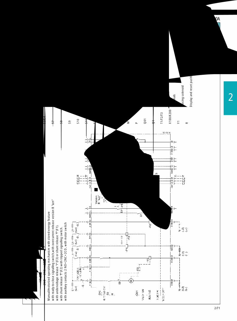
2/71
2
手动
/电动
机储
能操
作机
构带合
闸准备就绪信号发送触头,带
B型“
azn”
过电流脱扣器
带欠电压脱扣器
”r”
(F3)或分励脱扣器
”f”
(F1)
,带分励脱扣器
”f”
(F2),带脱扣信号发送触头
,带辅助触头
2NO+
2NC+
2CO,带电动机开关。
Man
ual/m
otor
ized
ope
ratin
g m
echa
nism
with
sto
red-
ener
gy f
eatu
rew
ith r
eady
-to-
clos
e si
gnal
ling
switc
h,w
ith o
verc
urre
nt r
elea
se v
ersi
on B
"azn
"w
ith u
nder
volta
ge r
elea
se "r
" (F3
) or
shun
t re
leas
e "f
" (F1
).w
ith s
hunt
rel
ease
"f" (
F2) w
ith t
rippe
d si
gnal
ling
switc
h.w
ith a
uxili
ary
cont
acts
2 N
O+
2NC
+2C
O, w
ith m
otor
sw
itch
断路器电气原理图 Example of full circuit diagramA
1带微处理器的电子式过电流脱扣器
Sol
id-s
tate
ove
rcur
rent
rel
ease
S1/
S2
第1辅助触头块
1st
aux.
cont
act
bloc
kS
3/S
4第
2辅助触头块
2nd
aux.
con
tact
blo
ckS
7合闸准备就绪信号发送触头
Rea
dy-t
o-cl
ose
sign
allin
g sw
itch
S8
储能触头
Sto
red-
ener
gy c
onta
ctS
9电动机开关
Mot
or s
witc
hS
10电气合闸按钮
Ele
ctric
al O
N p
ushb
utto
nS
11脱扣信号发送触头
Trip
ped
sign
allin
g co
ntac
tF1
第1分励脱口器
”f”
1st
shun
t re
leas
e "f
”F2
第2分励脱扣器
”f”
2nd
shun
t re
leas
e "f
”F3
欠电压脱扣器
”r”
Und
ervo
ltage
rel
ease
"r"
F5脱扣线圈
Rel
ease
sol
enoi
dM
储能电动机
Mot
or f
or c
harg
ing
"sto
red-
ener
gy m
echa
nism
"P
弹簧储能机构
Spr
ing
ener
gy m
echa
nism
Q01
用于储能的操作手柄
Ope
ratin
g ha
ndle
for
cha
rgin
g "s
tore
d-en
ergy
mec
hani
sm"
Q1
主触头
Mai
n co
ntac
tsT1
/T2/
T3电流互感器
Cur
rent
tra
nsfo
rmer
sX
100/
X20
0辅助回路接线端子
Term
inal
sY
1电气合闸线圈
Clo
sing
sol
enoi
dR
机械重合闸锁定复位按钮
Dis
play
and
res
et p
ushb
utto
n fo
r ov
ercu
rren
t re
leas
e
3WN6断路器,3极,至 3200A3WN6 Circuit-Breakers, 3-pole, up to 3200A
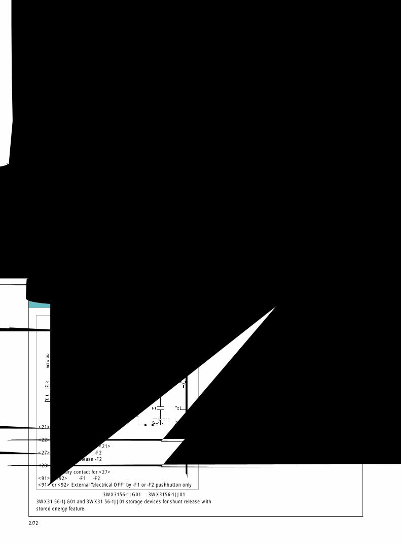
2/72
导向框架中断路器位置的信号发送开关 Signalling devices for circuit-breaker positions in the guide frame
退出位置Dis-connectedposition
订货码“R13”Order code"R13"3WX36 84-1JA10
运行位置Connectedpusition
试验位置Testposition
退出位置Dis-connectedposition
订货码“R14”Order code"R14"3WX36 84-1JC10
运行位置Connectedpusition
试验位置Testposition
触头已闭合Contact closed
触头已打开Contact open
触头状态表示:Contact position for :断路器在退出位置Circuit-breaker in disconnected position
断路器在试验位置Circuit-breaker in test position
断路器在运行位置Circuit-Breaker in connected position
辅助装置电气原理图 Circuit diagram for supplementary devices
-F1A用于第 1 个或第 2 个分励脱扣器的储能装置(-F1 或 -F2)
-F1AStorage device for 1st or 2nd shunt release (-F1 or -F2)
<21> 第 1 个分励脱扣器 -F11st shunt release -F1
<22> 用于<21>的辅助触头Auxiliary contact for <21>
<27> 第 2 个分励脱扣器 -F22nd shunt release -F2
<28> 用于<27>的辅助触头Auxiliary contact for <27>
<91>或<92>用于 -F1 或 -F2 的外部“电气分闸”按钮<91> or <92> External "electrical OFF" by -F1 or -F2 pushbutton only
用于带储能特征分励脱扣器的 3WX3156-1JG01 和 3WX3156-1JJ01 储能装置3WX31 56-1JG01 and 3WX31 56-1JJ01 storage devices for shunt release withstored energy feature.
3WN6断路器,3极和 4极,至 3200A3WN6 Circuit-Breakers, 3 and 4-pole, up to 3200A
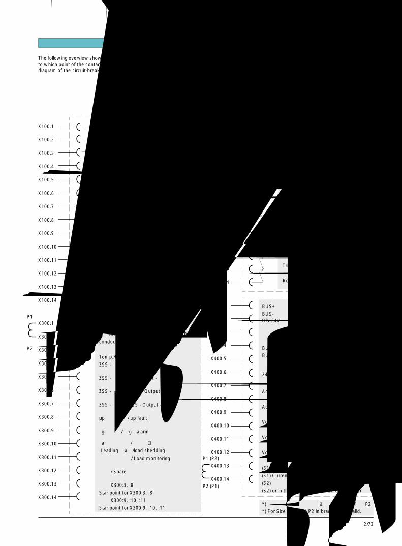
2/73
2
X200.1
X200.2
X200.3
或
X200.1
X200.2
X200.3
X200.4
X200.5
X200.6
X200.7
X200.8
X200.9
X200.10
X200.11
X200.12
X200.13
X200.14
X400.1
X400.2
X400.3
X400.4
X400.5
X400.6
X400.7
X400.8
X400.9
X400.10
X400.11
X400.12
X400.13
X400.14
3WN6断路器3WN6 Circuit-Breakers
S3
S3
第二辅助触头块 2CO
S4 Second auxiliary contact block
S4
储能电动机和电动机开关 (S9)
Motor and switch (S9)
电气合闸按钮 ON (S10)/ Electrical ON (S10)
电气合闸线圈 (Y1)/ Closing solenoid (Y1)
第二分励脱扣器 (F2)/ Voltage release (F2)
�
�
�
�
�
�
�
X100.1
X100.2
X100.3
X100.4
X100.5
X100.6
X100.7
X100.8
X100.9
X100.10
X100.11
X100.12
X100.13
X100.14
X300.1
X300.2
X300.3
X300.4
X300.5
X300.6
X300.7
X300.8
X300.9
X300.10
X300.11
X300.12
X300.13
X300.14
�
�
�
�
�
�
�
�
�
�
�
�
�
�
�
�
�
�
�
�
�
�
�
�
�
�
�
�
�
�
�
�
�
�
�
�
�
�
�
�
�
�
�
�
�
�
�
�
�
�
�
�
x
M
只用于 N 型和 P 型的安装于中性线的电流互
感器/Current transformer mounted in the N-
conductor, only for release N and P.
温度过高 / 相不平衡报警
Temp./Phase imbalance alarm
ZSS -输入 +/ ZSS - Input +
ZSS - 输入 - / ZSS - Input -
ZSS - 输出 + / ZSS - Output +
ZSS - 输出 - / ZSS - Output -
µp 故障报警 / µp fault
“g”报警 / “g”alarm
“a”前导信号 / 负载脱落信号
Leading “a”/load shedding
负载监控信号 / Load monitoring
备用 / Spare
用于 X300:3, :8 的星型接点
Star point for X300:3, :8
用于 X300:9, :10, :11 的星型接点
Star point for X300:9, :10, :11
S1
S2
{
欠压脱扣器 (F3)
Undervoltage release (F3) 两者取一
第一分励脱扣器 (F1)Shunt release (F1)
带延时欠压脱扣器 (F8)
Undervoltage release with delay (F8)
S1
S1
第一辅助触头块 (2NO+2NC)
First auxiliary contact block
S2
S2
脱扣信号发送触头 (S11)
Tripped signalling contact (S11)
合闸准备就绪信号发送触头 (S7)Ready-to-close signalling contact (S7)
BUS+
BUS-BIS 24V ;用于参数设定和触发开关 ON/OFF 的
工作电源 (采用 PROFIBUS DP 时用)Supply voltage for parameterizingand actuator ON/OFF (PROFIBUS DP)
BUS 星型接点处接线 (接地)BUS star-point conductor (ground)
备用 / Spare
24V DC
触发开关 ON (通过 PROFIBUS DP)
Actuator switch ON (via PROFIBUS DP)
触发开关 OFF (通过 PROFIBUS DP)
Actuator switch OFF (via PROFIBUS DP)
电压互感器 L1
Voltage transformer L1
电压互感器 L2
Voltage transformer L2
电压互感器 L3
Voltage transformer L3
电压互感器星型接点/Voltage transformer star point
(S1) 安装于中性线的电流互感器
(S1) Current transf. installed in the N-conductor
(S2) 或安装于变压器的星型接点处(S2) or in the starpoint of the LV transformer
{
P1 (P2)
P2 (P1)
P1
P2
下图显示了内部接点的外部端子排之间的联接。The following overview shows which point internal equipment is connectedto which point of the contact blocks, i.e. this is a complete auxiliary wiringdiagram of the circuit-breaker.
*)对于框架等级 I,应采用括号中的字母 P1 和 P2*) For Size 1 P1 and P2 in brackets are valid.
{端子图 Terminal diagrams
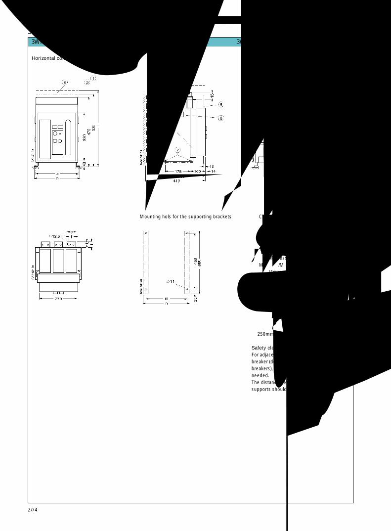
2/74
3WN6固定式断路器,3极 3WN6 fixed-mounted circuit-breakers, 3-pole主回路水平连接Horizontal connection
支持托架的安装孔Mounting hols for the supporting brackets
① 取出灭弧室所需的空间Clearance for removing the arc chute
② 辅助接线端子所需的空间Clearance for auxiliry connector
③ 灭弧空间 /Arcing space④ 辅助接线端子 /Auxiliary connector⑤ 开关柜门 /Cubicle door⑥ 凹柄 /Recessed grip⑦ M8 螺母 /M 8 nut⑧ 狭槽(4mm深)用于安装相间隔板(不供货)
Slots (4 mm deep) for phase separatingbarriers (not supplied)
⑨ 断路器中心线 /Circuit-breaker centre-line
安全间隙断路器上方与邻近接地部件之间不需留出
额外的安全间隙(固定式断路器中标号③)。连接位置和母排支持件之间的距离不应超
过 250mm。
Safety clearancesFor adjacent earthed parts above the circuit-breaker (designated ③ for fixed-mountedbreakers), no additional safety clearance isneeded.The distance between connections and barsupports should not exceed 250 mm.
3WN6断路器,3极和 4极,至 3200A3WN6 Circuit-Breakers, 3 and 4-pole, up to 3200A

2/75
2
3WN6断路器3WN6 Circuit-Breakers
主回路前置连接 /Connection accessible from the front
单孔Single-hole
双孔 /Double-hole母排末端孔洞符合 DIN 43 673 标准Holes in bar ends acc. to DIN 43 673
3WN6固定式断路器,3极 3WN6 fixed-mounted circuit-breakers, 3-pole
如果母排系统不是放置于断路器上方,则在额定工作电压至AC415V时,垂直母排(例如母排前置)不需要任何防护措施。
如果电压高于 AC415V,断路器上方的裸露的带电导体或上进线的导体必须借助于相间隔板,母排罩或消弧罩盖(附件)加以绝缘,以防止飞弧。
如果电气辅助装置直接安装在断路器顶上(若没采用消弧罩盖)或断路器的侧面,应采用消弧罩盖加以保护。
同时,附加的罩盖和相间隔板不应防碍断路器的散热。If the bar system is not placed over thecircuit-brekaer, vertical bars (as for instancein the case of connection accessible fromthe front) do not require any shielding up to arated operational voltage of 415V AC.Note that, for voltages above 415V AC, liveblank conductors and bars placed over thecircuit-breaker or with feed-in from abovemust be insulated against flashovers bymeans of phase-separating barriers, barcovers or the arc chute cover (Accessories).Supplementary electrical devices mounteddirectly above the circuit-breaker (if no arcchute cover is used) or on its side should beprotected with a cover. Furthermore itshould be ensured that additional covers andseparating barriers do not hinder theelimination of heat from the circuit-breaker.
额定电流Rated currentA a b c d e f g h i k l m n
630 to1000 300 320 90 8 60 30 - 8 530 18 40 300 3381250 to1600 300 320 90 15 60 30 - 20 530 18 40 300 3382000 400 420 120 15 80 40 40 20 560 22 44 400 4382500 to 3200 400 420 120 30 80 40 40 20 560 22 44 400 438
主回路连接Main conductor connections
螺钉接线端子,带压紧垫圈 M12Screw-type terminal with clamping spacers(内径 =12mm,按照 DIN6769-Fst标准)(Inner diameter=12mm acc. to DIN 6769-Fst)
推荐的拧紧力矩 Nm 70Recommended tightening torque
所需的螺钉强度 8.8 按照 DIN 267 标准Required screw strength 8.8 acc. to DIN 267

2/76
3WN6抽屉式断路器,3极 3WN6 draw-out circuit-breakers, 3-pole
主回路水平连接Horizontal connection
主回路垂直连接Vertical connection
a. 退出位置Disconnected position
b. 试验位置Test position
c. 运行位置Connected position
① 辅助导线的插入式接线端子Plug-in terminals for auxiliaryconnecting leads
② 导向框架Guide frame
③ 开关柜门Cubicle door
④ 狭槽(6mm深)用于安装相间隔板(不供货)Slots (6mm deep) for phase-seprating barriers (not supplied)
⑤ 固定导向框架的孔Holes for fixing the guide frame
⑥ 断路器的中心线Circuit-breaker centre-line
有关安全间隙的描述,见第 2/74页For safety clearances, see page 2/74
额定电流Rated currentA a b c d e f h i k l m n
630 to 1000 280 320 90 8 60 30 455 470 157,5 115 37 901250 to 1600 280 320 90 15 60 30 455 470 157,5 115 37 902000 380 420 120 15 80 40 465 480 157,5 115 40 1402500 to 3200 380 420 120 30 100 50 465 480 150 130 40 140
3WN6断路器3WN6 Circuit-Breakers

2/77
2
3WN6断路器3WN6 Circuit-Breakers
3WN6抽屉式断路器,3极 3WN6 draw-out circuit-breakers, 3-pole
主回路前置连接connection accessible from the front
单孔,630~1600 ASingle-hole, 630 to 1600 A
双孔,630~1600 A孔洞符合 DIN 43 673 标准Double-hole, 630 to 1600 AHoles in bar ends acc. to DIN 43 673
单孔,2000~3200 ASingle-hole, 2000 to 3200 A
双孔,2000~3200 A孔洞符合 DIN 43 673 标准Double-hole,2000 to 3200 AHoles in bar ends acc.to DIN 43673
额定电流Rated currentA a b c d e
630 to 1000 60 - 8 390 4081250 to 1600 60 - 15 390 4082000 80 40 20 420 4452500 to 3200 100 50 20 420 445
① 导向框架Guide frame
② 开关柜门Cubicle door
③ 狭槽(6mm深,3.5mm 宽)用于安装相间隔板(不供货)Slots (6mm deep, 3.5mm wide) forphase-separating barriers (not supplied)
④ 断路器的中心线Circuit-breaker center-line
有关安全间隙的描述,见第 2/74页For safety clearances, see page 2/74
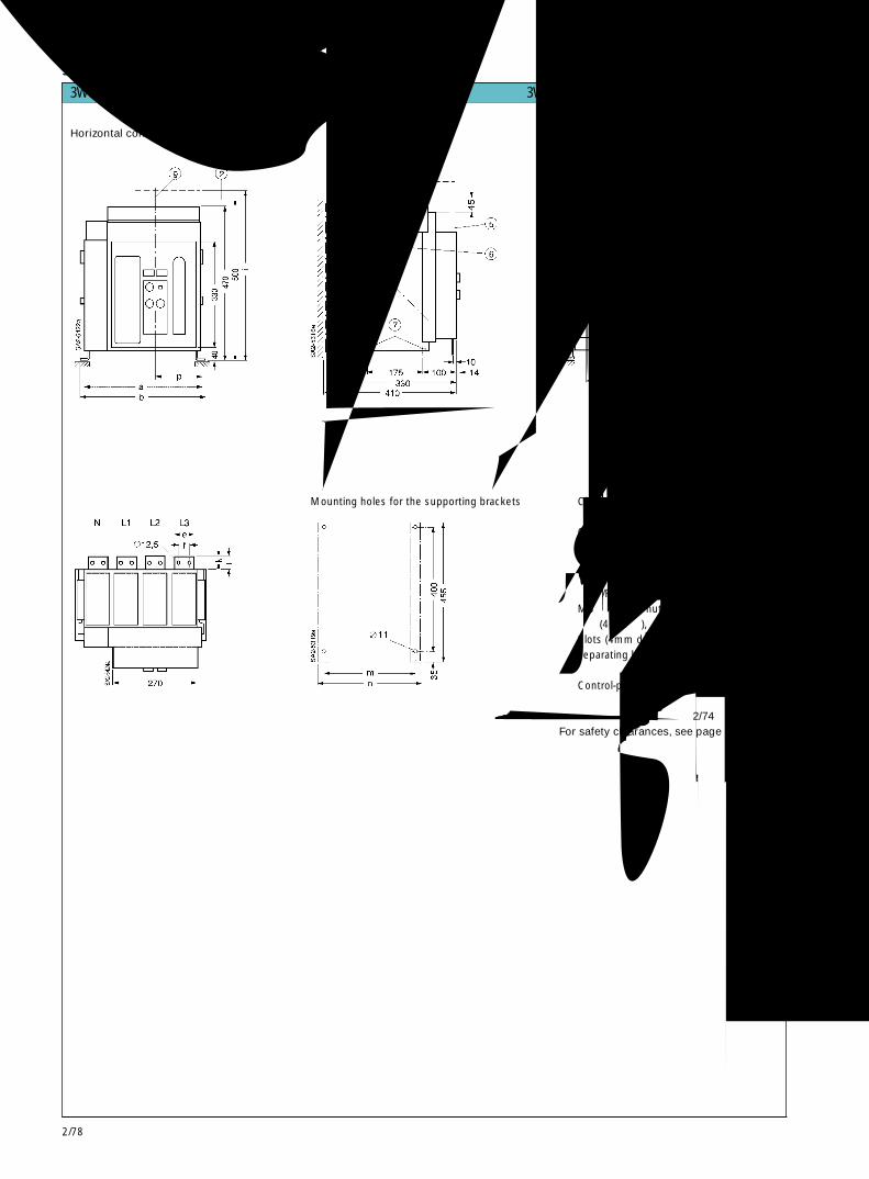
2/78
3WN6固定式断路器,4极 3WN6 fixed-mounted circuit-breakers, 4-pole
主回路水平连接Horizontal connection
支持托架的安装孔Mounting holes for the supporting brackets
① 取出灭弧室所需的空间Clearance for removing the arc chute
② 辅助接线端子所需的空间Clearance for auxiliry connector
③ 灭弧空间 /Arcing space④ 辅助接线端子 /Auxiliary connector⑤ 开关柜门 /Cubicle door⑥ 凹柄 /Recessed grip⑦ M8 螺母 /M 8 nut⑧ 狭槽(4mm深),用于安装相间隔板(不供货)
Slots (4mm deep) for phase-separating barriers (not supplied)
⑨ 控制面板中心线Control-panel centre-line
有关安全间隙的描述,见第 2/74页For safety clearances, see page 2/74
3WN6断路器3WN6 Circuit-Breakers
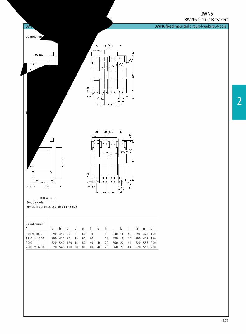
2/79
2
3WN6断路器3WN6 Circuit-Breakers
主回路前置连接connection accessible from the front
额定电流Rated currentA a b c d e f g h i k l m n p
630 to 1000 390 410 90 8 60 30 - 8 530 18 40 390 428 1501250 to 1600 390 410 90 15 60 30 - 15 530 18 40 390 428 1502000 520 540 120 15 80 40 40 20 560 22 44 520 558 2002500 to 3200 520 540 120 30 80 40 40 20 560 22 44 520 558 200
单孔Single-hole
双孔孔洞符合 DIN 43 673 标准Double-holeHoles in bar ends acc. to DIN 43 673
3WN6固定式断路器,4极 3WN6 fixed-mounted circuit-breakers, 4-pole
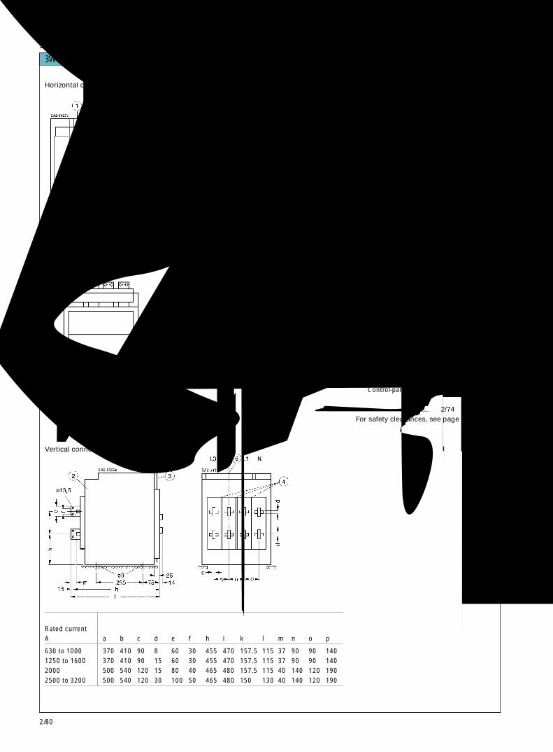
2/80
3WN6断路器3WN6 Circuit-Breakers
3WN6抽屉式断路器,4极 3WN6 draw-out circuit-breakers, 4-pole
主回路水平连接Horizontal connection
主回路垂直连接Vertical connection
额定电流Rated currentA a b c d e f h i k l m n o p
630 to 1000 370 410 90 8 60 30 455 470 157.5 115 37 90 90 1401250 to 1600 370 410 90 15 60 30 455 470 157.5 115 37 90 90 1402000 500 540 120 15 80 40 465 480 157.5 115 40 140 120 1902500 to 3200 500 540 120 30 100 50 465 480 150 130 40 140 120 190
a. 退出位置Disconnected position
b. 试验位置Test position
c. 运行位置Connected position
① 辅助导线的插入式接线端子Plug-in terminals for auxiliaryconnecting leads
② 导向框架Guide frame
③ 开关柜门Cubicle door
④ 狭槽(6mm深)用于安装相间隔板(不供货)Slots (6 mm deep) for phase-separatingbarriers (not supplied)
⑤ 固定导向框架的孔holes for fixing the guide frame
⑥ 控制面板的中心线Control-panel centre-line
有关安全间隙的描述,见第 2/74页For safety clearances, see page 2/74

2/81
2
3WN6抽屉式断路器,4极 3WN6 draw-out circuit-breakers, 4-pole
主回路前置连接connection accessible from the front
单孔,630~1600 ASingle-hole, 630 to 1600 A
双孔,630~1600 A孔洞符合 DIN 43 673 标准Double-hole, 630 to 1600 AHoles in bar ends acc. to DIN 43 673
单孔,2000~3200 ASingle-hole, 2000 to 3200 A
双孔,2000~3200 A孔洞符合 DIN 43 673 标准Double-hole,2000 to 3200 AHoles in bar ends acc.to DIN 43673
额定电流Rated currentA a b c d e
630 to 1000 60 - 8 390 4081250 to 1600 60 - 15 390 4082000 80 40 20 420 4452500 to 3200 100 50 20 420 445
① 导向框架Guide frame
② 开关柜门Cubicle door
③ 狭槽(6mm 深,3.5mm 宽)用于安装相间隔板(不供货)Slots (6 mm deep, 3.5mm wide) forphase-seprating barriers (hot supplied)
④ 控制面板的中心线Control-panel centreline
有关安全间隙的描述,见第 2/74页For safety clearances, see page 2/74
3WN6断路器3WN6 Circuit-Breakers
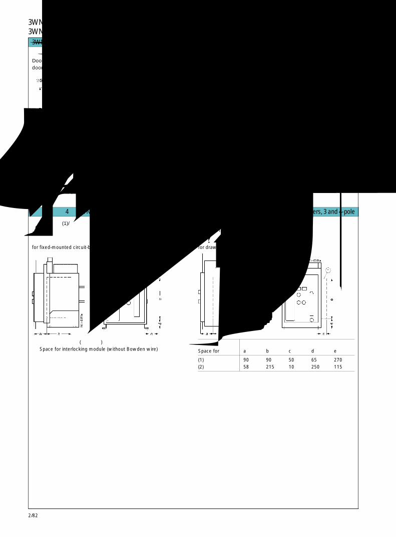
2/82
3WN6断路器3WN6 Circuit-Breakers
相互机械联锁(1)/防止合闸的锁定装置(2)/Mutual mechanical Interlocking (1)/Locking device against closing (2)包括柜门上的锁和带钢缆的联锁模块。/consisting of lock in the cubicle door and interlocking module with Bowden wire
用于固定式断路器for fixed-mounted circuit-breaker
用于抽屉式断路器for draw-out ciruit-breakerr
所需空间,用于Space for a b c d e
(1) 90 90 50 65 270(2) 58 215 10 250 115
3WN6断路器,3极和 4极 3WN6 circuit-breakers, 3 and 4-pole
采用门密封框时,适于控制面板的柜门开孔图Door cutout for control panel usingdoor sealing frame
控制面板安装边缘保护边后的柜门开孔图Door cutout with edge protectorCutout after mounting of edge protector
①安装表面Mounting surface
* 3 个 ø5mm 的孔,仅用于门锁3 holes ø5mm should only be executed for the door lock
断路器安装于开关柜内,并位于柜门中心线时的柜门开孔。Cutout for installation of the circuit-breakerinside a cubicle and with central position of thedoor.
柜体宽度 固定式 抽屉式Field width Fixed-mounted Draw-out
b b
400 275 292500 275 290600 275 288
用于 3极和 4极 3WN6断路器的附件 Accessories for 3WN6 circuit-breakers, 3 and 4-pole
① 联锁模块所需空间(不带钢缆)Space for interlocking module (without Bowden wire)
2/83
2
用于 3极和 4极 3WN6断路器的附件 Accessories for 3WN6 circuit-breakers, 3 and 4-pole
用于分励脱扣器的 3WX3156- 1J.01/储能装置/3WX31 56-1J.01 storage for shunt release
① 安装脚Mounting feet
② 按照 DIN EN 50022-35 的标准安装导轨Standard mounting rail acc.to DIN EN 50 022-35
用于N导线过载保护与接地故障保护的电流互感器Current transformer for protectlon against overload in the N conductor and earth-fault用于尺寸等级 I和 IIfor sizes I and II
3WX36 43-1..00
电流互感器 电流互感器 尺寸等级原边额定电流
Current transformer Current Size A B C D E Ftransformer approx.primaryrated currentIN
3WX36 43-1 . . 00 A
CA 315 I 92 60 86.5 140 5⋯15 107CB 400CC 500CD 630CE 800CF 1000CG 1250CH 1600
FJ 2000 II 128 80 99 167 5⋯35 136FK 2500FM 3200
用于电气合闸和机械分闸按钮的锁定装置Locking device for Electrical ON and Mechanical OFF button
电源转换装置Network switching control-unit
安装于柜子中的侧视图和正视图Installation in the cubicle, Side view and front view
开孔图,外形尺寸Hole positions, Externaldimensions
3WN6断路器3WN6 Circuit-Breakers
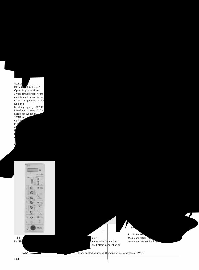
2/84
3WN1交流断路器3WN1 Circuit-Breakers for AC描述 Descriptlon
符合标准:DIN VDE0660,IEC947
工作条件3WN1断路器一般用于非恶劣工作条件的密
闭区域中。设计分断能力:80/100kA额定工作电流:630A 至 6300A额定工作电压:690/1000VAC
3WN1断路器配有过电流脱扣器、操作机构和辅助触头,如果需要还可配带欠电压脱扣器和分励脱扣器。负荷隔离开关不带过电流脱扣器。过电流脱扣器
微处理器控制的电子式过电流脱扣器系统不需要独立电源供电,可满足配电系统、电动机、变压器和发电机等负载的各种保护要求。
StandardsDIN VDE 0660, IEC 947Operating conditions3WN1 circuit-breakers are climate-proof. Theyare intended for use in enclosed areas, whereexcessive operating conditions do not occur.DesignsBreaking capacity: 80/100kARated oper. current: 630 to 6300ARated oper.voltage: AC 690/1000V3WN1 circuit-breakers are supplied fullyequipped with overcurrent releases, operatingmechanism and auxiliary contacts and, ifrequired, with auxiliary releases.Non-automatic circuit-breakers are alwayssupplied without overcurrent release system.Overcurrent releasesThe solid-state, microprocessor-controlledovercurrent release system does not dependon a separate power supply and permits thevarious protection requirements of distributionsystems, motors, transformers and generatorsto be taken into account.
1 抽屉式断路器2 显示和复位按钮,用于断路器脱扣后
-脱扣信号发送触头-机械重合闸锁定
3 储能状态指示器4 通断状态指示器5 带密封盖的机械合闸按钮6 机械分闸按钮7 电气合闸按钮8 前置透明面罩的过电流脱扣器9 断路器在导向框架中的位置显示10 导向框架11 延长导轨12 辅助接线端子13 带连接母排(双孔)的主接线端子14 手动操作手柄
1 Draw-out circuit-breaker2 Display and “RESET” button for
- tripped signaling contact- mechanical reclosing lockout after circuit-breaker has tripped
3 Stored-energy status indicator4 Switching-state indicator5 ON button, mechanical, with sealing cap6 OFF button, mechanical7 ON button, electrical8 Overcurrent release9 Position indicator10 Guide frame11 Hinged rails12 Auxiliary connectors13 Main connections with connecting bars
(double-hole)14 Lever for manual operating mechanism
图 87 3WN1 抽屉式断路器尺寸等级 I,3 极Fig. 11/87 3WN1 draw-out circuit-breaker, size I, 3-pole
图 89 导向框架上部带用于水平母排连接的 T 形件,下部用于垂直母排连接Fig. 11/89 Guide frameMain connections above with T-pieces forhorizontal connection, Bottom connection tovertical busbars
图 90 导向框架主回路连接为加长连接母排,可从前方连接Fig. 11/90 Guide frameMain connections with extended busbars, forconnection accessible from the front
欲了解 3WN1的详细情况,请与就近的西门子办事处联系。/ Please contact your local Siemens office for details of 3WN1.
图 88 过电流脱扣器Fig. 11/88 Overcurrent release
2/85
2
描述
具有通讯能力的断路器 3VL,3WN6,3WN1,3WS1Communication-Capable 3VL, 3WN6, 3WN1, 3WS1 Circuit-Breakers
Description
PROFIBUS-DP具有通讯能力断路器的数据的传送是通过已
标准化的(EN50170 标准),且与生产商无关的PROFIBUS-DP 现场总线系统传输至高一级的可编程序控制器(如SIMATIC S5)(见下页选择和功能表)。总线技术使如下特点成为可能:● 经济的方案设计、接线和调试● 远距离控制及快速故障诊断,因而避免了不必要的维护检查,减少了工厂停机时间
● 灵活性: 如果系统要求有所变化,可更改参数设置
● 顺序接通和断开负载,可避免代价昂贵的负载峰值-实现了能量管理
具有通讯能力的断路器被用于经济地实现工厂设备的高利用率。
具有通讯能力断路器的选择● 具有通讯能力 3VL 断路器通常包括如下配置:
1. 一台塑壳式断路器(见 3VL 一章)
2. 一个电动机操作机构用于使断路器合 / 分闸(见 3VL 一章有关附件)
3. 用于 3VL 断路器的改进型 SIMOCODE-DP(SIMOCODE-DP 的测量范围包含了断路器的电流调节范围Ir)
4. 必要的附件,见第 2/92 页为快速选型,第2/89页列出了订货号和相应的电动机操作机构和 SIMOCODE-DP 的订货号。
● 对具有通讯能力的 3WN6断路器的选型描述见第 2/86 页。为快速选型,第2/90页上列出了推荐的订货号。
● 对具有通讯能力的 3WN1或3WS1断路器的选型,应注意如下要点:1. 断路器订货号的第10位改用字母“R”(“azn”
保护)或“V”(“azng”保护)(用于接地故障保护)
2. 订货号后缀加“-Z”和订货代号“F01”3. 当选用抽屉式断路器时,导向框架订货号后
缀加“-Z”和订货代号“R39”。4. 必要的附件列于第 2/94 页。
为快速选型,第 2/91 页列出了推荐的订货号。
PROFIBUS-DPData from communication-capable circuit-breakers is transmitted via the standardized(EN 50 170), manufacturer-neutral PROFIBUS-DP bus system to higher-level programmablecontrollers (e.g. SIMATIC S5). (See chart innext page for selection and functions)
Bus technology makes possible:● economical project planning, wiring and
commissioning
SPS:可编程控制器 PC:个人计算机PLC PG:编程装置
PLC: Programmable PC: Personal ComputerController PG: Programming Device
● remote control as well as quick faultdiagnosis and thus preventive maintenanceand shorter downtime of the plant
● flexibility: modifying the setting parameters incase of changed requirements
● serial switching on and off of loads to avoidexpensive load peaks-power management.
Communication-capable circuit-breakers areused to achieve high plant availabilityeconomically.
Selection of communication-capablecircuit-breakers● Communication-capable 3VL circuit-breakers
usually consist of:1. A conventional circuit-breaker (see
Section 4)2. A motorized operating mechanism for
switching on/off (see Section 4Accessories)
3. SIMOCODE-DP modified for the 3VLcircuit-breaker (SIMOCODE -DPmeasuring range covers the circuit-breakeradjustment range Ir)
4. Necessary accessories listed on page 2/92
For quick selection, on page 2/89 there areprepared Order No. for selected 3VLcommunication-capable circuit-breakers andcorresponding motorized operatingmechanisms and SIMOCODE-DP.
● For general selection of communication-capable 3WN6 circuit-breakers seedescription on page 2/86 For quick selectionthere are prepared Order No. for selectedmodels on page 2/89.
● For general selection of communication-capable 3WN1 or 3WS1circuit-breakers thefollowing criteria should be noticed:1. Modify the 10th position of the circuit-
breaker Order No. adding the trigger letter"R" ("azn") or "V" ("azng") (for earth faultprotection).
2. Supplement the Order No. with "-Z" andthe code "F01".
3. When ordering withdrawable circuit-breakers, supplement the guide frameOrder No. with "-Z" and the code "R39".
4. The accessories listed on page 2/94 arerequired.
For quick selection there are prepared OrderNo. for selected 3WN1 circuit-breakers; seepage 2/91.

2/86
断路器 3VL 3WN6 3WS1/3WN1(至 800A) (至 3200A) (至 2500/6300A)
Circuit-breakers(up to 800 A) (up to 3200 A) (up to 2500/6300 A)
采用的接口 SIMOCODE-DP DP/3WN6 DP/3WN1, 3WS1 ET 200Interface used (3UF50)
使断路器合/分闸指令Circuit-breakeron/off command + + - +
运行状态 Operational status● 合/分闸 ● ON/OFF + + - +● 合闸准备就绪 ● Ready to start - + - +(断路器应带有 "-Z"
和订货码 "M10")
(Circuit-breaker with"-Z" & order code"M10")
故障信息 Event information● 脱扣信号 ● Tripped signal + + + +(断路器应带有 "-Z"
和订货码 "M02")
(Circuit-breaker with"-Z"& order code"M02")
● 过载报警 ● Overload warning + + + +
数据读取 Readings● 最大相电流Imax ● Max. phase + + + -
current Imax
● 电流IL1,IL2,IL3 ● Currents: IL1, IL2, IL3 - + + -● 电流IN ● Current IN - + - -
能量管理 Energy management (通过 PROFIBUS 计 +(断路器带“-Z”和 (通过 PROFIBUS计量)● 功率(P), ● Power (P), 量) 订货码“F05” 有效功(W), Workload (W), (Use PROFIBUS (Circuit-breaker with (Use PROFIBUS meter) 功率因数,电压 Power factor, Voltage meter) "-Z" & order code
"FO5")
通过总线设置参数 Parameter settings via + + -(如脱扣电流值) bus (e.g. tripping 由 SIMOCODE-DP
current) 读取SIMOCODE-DPreading
概览:具有通讯能力断路器的功能一览表
具有通讯能力的断路器 3VL,3WN6,3WN1,3WS1Communication-Capable 3VL, 3WN6, 3WN1, 3WS1 Circuit-Breakers
Overview: Functions of communication-capable circuit-breakers

2/87
2
用于 SIMATIC S5/S7的软件包Software module for SIMATIC S5/S7
连接电缆3WN6-DP 至 3WN6(3m 长,随 3RK1 供货)Connecting cable3WN6-DP / 3WN6(interface includes 3m)
描述
具有通讯能力的断路器 3WN6,至 3200ACommunication-Capable 3WN6 Circuit-Breakers, up to 3200A
Description
右图所示的硬件和软件对于配置通过PROFIBUS 通讯的 3WN6 系统来说是必需的。
过电流脱扣器应采用具有附加功能2的过电路脱扣器 D,E/F,H,J/K,N 或 P 型。
与一般的3WN6断路器相比,具有通讯能力的3WN6断路器带有一个通讯模块。如需要增加测量功能,应采用配置为带有计量功能通讯模块的 N 型,P 型过电流脱扣器。
增加的测量功能:1.测量:
● 相电流● 相序● 频率● 有功功率,无功功率和视在功率● 功率因数
2.报警 / 脱扣整定值设定 用于:● 相不平衡● 能量流向● 频率过高,频率过低● 过电压,欠电压
The hardware and software shown on the rightis required for communication with the 3WN6circuit-breaker via the PROFIBUS.
Basically communication-capable are theovercurrent releases D, E/F, H, J/K, N or Pusing additional function 2.
In contrast to standard circuit-breakers the3WN6 communication-capable circuit-breakerhas an extra communication module. Forexpanded meter functions, release N, Prequires a communication module with ameter (meter module) instead of the standardcommunication module.
Expanded meter functions:1 Measurement of:
● phase current
注意要点 Notes
● phase direction● frequency● Effective power, reactive and apparent
power● Performance factor
具有通讯能力 3WN6断路器的基本选型要求● 在断路器订货号的第8个位置上填入“7”,使过电流脱扣器具有“附加功能 2”
● 在断路器订货号的第10个位置上填入过电流脱扣型号(D 型至 P 型)
● 对于通讯模块,订货号最后加“-Z”和订货码“F01”● 对于通讯模块带测量功能,订货号最后加“-Z”和订货码“F05”
● 推荐采用断路器脱扣后自动复位功能,订货号最后加“-Z”和订货码“K01”
● 有关 3WN6 的详细介绍请见本章
注意要点 1若分别订购带通讯能力的抽屉式3WN6断路
器本体和导向框架,订货号写法如下:抽屉式断路器本体(不带导向框架)的订货号
为在订货号的第 6 个位置中填入“7”。断路器的订货号:3WN6● 7● -7● ● ● ● -● ● ● ● - Z F01 或 F05导向框架的订货号:3WX3683-● A● ● 0-Z R39
注意要点 2通过PROFIBUS实现断路器远距离合闸需要
一个电动机储能操作机构和合闸线圈(Y1),通过PROFIBUS实现断路器远距离分闸,需配备一个F1或 F2分励脱扣器,配置具有通讯功能的断路器需如下附件:● 系统手册(用于方案设计和调试)● DP/3WN6 接口● 给接口供电的直流 24V 电源● PROFIBUS 连接器和连接线
2 Alarm / trip settings for:● Phase unbalance voltage● Energy flow direction● Overfrequency, underfrequency● Overvoltage, undervoltage
采用 SIMATICS5/S7 实现完整的通讯系统需:软件模块。
为快速选型,本章第2/90页列举了常用订货号。
Ordering information points on generalselection of communication-capable 3WN6circuit-breakers● For the "additional function 2" enter a "7" in
the 8th position of the circuit-breaker OrderNo.
● Enter the release type ("D" to "P") in the 10thposition of the circuit-breaker Order No.
● For the communication module, supplementthe Order No. with "-Z" and the order code"F01"
● For the communication module + meter,supplement the Order No. with "-Z" and theorder code "F05"
● Automatic resetting after the circuit-breakerhas tripped is recommended. Supplementthe Order No. with "-Z" and order code "K01"
● For the detail information of 3WN6, pleasesee the referent section
Note 1When ordering communication-capable guideframes and 3WN6 withdrawable circuit-breakers separately, two Order Nos. must beentered.
When ordering withdrawable circuit-breakerswithout guide frames, enter "7" in the 6thposition of the Order No. (see also Section 5)Circuit-breaker Order No.:3WN6● 7● -7● ● ● ● -● ● ● ● with "-Z" and ordercode "F01" or "F05"Guide frame Order No:3WX36 83-● A● ● 0 with "-Z" and order code"R39"
Note 2Remote closing of the circuit-breaker viaPROFIBUS requires a motorized operatingmechanism with a stored energy mechanismclosing solenoid (Y1). For remote opening of3WN6 via PROFIBUS the circuit-breakermust be equipped with a F1 or F2 shuntrelease
Communication-capable circuit-breakersrequire the following accessories● System manual (to support project planning
and commissioning)● DP/3WN6 interface● DC power supply 24 V for interface● PROFIBUS connectors and bus lines
Use of the complete communication packagewith SIMATIC S5/S7 requires: softwaremoduleFor quick selection, see prepared Order Nos.for selected models on page 2/90.
PC/ 编程单元(带 COM PROFIBUS 软件)PC / Programming device(with COM PROFIBUSsoftware)
GSD 文件(随 3RK1 供货)Type / GSD file (incl. in DP/3WN6)
PROFIBUS-DP接口Anschaltung
插头Plug 6ES7
3WN6 断路器3WN6 circuit-breaker
给合闸线圈(Y1)和分励脱扣器(F1,F2)供电Power supply for closing solenoid (Y1)and shunt release (F1, F2)
供电电源Power supply
过电流脱扣器D, E/F, H, J/K,N 或 P+附加功能 2+通讯模块 F01Overcurrent releaseD, E/F, H, J/K, N or P+ Additional function 2+ Communicationmodule F01
过电流脱扣器 N 或 P+附加功能 2+带测量功能的通讯模块 F05Overcurrent release Nor P+ Additional function 2+ Communicationmodule with meterF05
能量管理,信号发送...Energy management,Signals...
测量电流,信号发送...Measuring current,Signals...
PLC

2/88
描述
具有通讯能力的断路器 3WN6,至 3200ACommunication-Capable 3WN6 Circuit-Breakers, up to 3200A
Description
高性能的软件包可以简化断路器的操作,也可以更方便地使用断路器的通讯功能。
Win3WN6● 该软件提供了 3WN6断路器从参数设置、操作控制和监控的所有功能。
软件特点● 可用于 D, E/F, H, J/K, N 和 P 型脱扣器。● 在 Windows 95 和 Windows NT 4.0 操作系统下运行。
● Win3WN6 通过断路器脱扣器面板上的 RS232接口或通过PROFIBUS-DP, 以SIMATIC S5, S7或 PC 机为主机与断路器进行通讯。
● 观察断路器的运行状态和脱扣信号● 对断路器进行操作(可加密码保护)。● 观测运行参数(如相电流)。● 方便地设定保护参数(可加密码保护)。
Win3WN6的优点● 参数设置方便快捷,节省时间(只要一次输入参数,然后将其拷贝至其他相同设置的断路器)。
● 只要按一下按钮即可快速读出断路器的参数并打印出来。
● 只要点一下鼠标,即可得出断路器的诊断数据,避免了 / 减少了停电检修时间。
SICAM LCC可使用户方便经济而快捷地创建工厂电器设
备的图形化操作界面。SICAM LCC适用于中小型工厂使用。
软件特点用于 3VL, 3WN6, 3WN1, 3WS1 断路器和
SIMOCODE-DP 电动机保护和控制装置。● 在 Windows 95 和 Windows NT 4.0 操作系统下运行。
● 配置:在PROFIBUS-DP上以SIMATIC S5, S7或 PC 机为主机。
● 显示电器设备示意图包括重要的数据信息。● 测量值的显示和分析(最小值 / 最大值 / 平均值 /曲线图,例如电流曲线图)。
● 事故列表● 报警列表● 打印,记录● 调用其他软件(如Win3WN6; Win-SIMOCODE-
DP)● 调用电器设备的参数(调用 Win3WN6, Win-
SIMOCODE-DP)
SICAM LCC的优点● 为工厂配电用电器设备提供了清楚的标准图形界面。
● 只要按一下按钮即可快速读出电器设备的参数并打印出来。
● 通过对所有连接的电器设备进行诊断可避免/减少工厂的停电检修时间。
● 通过对测量值(如电流值)进行分析,可实现最佳的能量管理,减小负载峰值。
● 采用标准工具实现图形化操作,减少了成本。
High-performance software packages areavailable for easy operator control and use ofthe communication function of the circuit-breakers.
Win3WN6● offers the user the whole range of functions
of the 3WN6 circuit-breaker for start-upprocedures, operator control and monitoringat an attractive price.
Software features● For release models D, E/F, H, J/K, N and P● Runs on Windows 95 and Windows NT 4.0● Win3WN6 communicates with the circuit-
breaker either via the RS232 interface (at therelease instead of the manual control) or viathe PROFIBUS-DP, SIMATIC S5, S7 or PC asa master
● Overview of circuit-breaker status andtripped signals (see diagram)
● Switching operations (password-protected)● Overview of operating data (e. g. phase
currents)● Easy setting of protective parameters
(password-protected)
Advantages of Win3WN6● Efficient start-up procedures save time
(-input parameters once and then copy themto different circuit-breakers)
● Quick and easy documentation of circuit-breaker parameters at the touch of a button
● Avoiding-/-minimizing plant downtimethrough specific diagnosis with access to allcircuit-breaker data at the click of a mouse.
SICAM LCCallows the user to create a standard plantvisualization simply, economically, and in avery short time. SICAM LCC is used for smallto medium-sized plants.
Software features● For 3VL, 3WN6, 3WN1, 3WS1 circuit-
breakers and for SIMOCODE-DP motorprotection and control units
● Runs on Windows 95 and Windows NT 4.0,● Configurations: SIMATIC S5, S7 or PC as
master on PROFIBUS-DP● Detailed diagrams of devices including the
most important information● Measured-value display and analysis (min /
max /average/graphs, e.g of currents)● Events lists● Alarm lists● Printing, logging● Calling of other available software (Win
3WN6 see above; Win-SIMOCODE-DP, seethe Controls and Distribution Catalog)
● Device parameters adjustable (call up Win3WN6, Win-SIMOCODE-DP)
Advantages of SICAM LCC● Clear standard visualization (energy
distribution) of the plant displaying allimportant information.
● Quick and easy plant documentation at thetouch of a button
● Avoiding / minimizing plant downtimethrough specific diagnosis with access to allconnected devices
● Measured-value-processing (e.g. of currents)for optimal energy consumption, e.g. forreducing peak loads (energy management)
● Cost-saving visualization using a standardtool
Win3WN6 屏幕显示Win3WN6 main overview screen
2/89
2
具有通讯能力的 3VL系列断路器,至 800A,用于固定式安装,3极Communication-Capable 3VL Circuit-Breakers, up to 800A, for Fixed Mounting, 3-pole
选型和订货参数
额定工作电压Ue 至AC 690V 通过 PROFIBUS-DP 可传送:带辅助开关(1 转换) ● 断路器分/合闸指令带报警开关(1 转换) ● 运行状态信号(断路器分/合闸)带电动机操作机构(AC 220 - 240V)(需另外 ● 脱扣信号订货)1) ● 过载信号详细技术参数见 3VL 一章 ● 最大相电流 (Imax)3VL 实现通讯需要 SIMOCODE-DP 接口 ● (SIMOCODE-DP)设定值的修改
详细描述见第 2/86 页
Selection and ordering data
额定 过载反时限 短路瞬时 断路器 所需的电动机操作机构 接口:电流 脱扣器 “a” 的 脱扣器 “n” 的 Circuit-breakers (AC 220 - 240V) SIMOCODE-DP 电动机Rated 整定电流值Ir 整定电流值Ii Required motorized 保护和控制装置current operating mechanism Interface:In AC 220 to 240 V 1) SIMOCODE-DP motor
protection and control device
Setting current Operating 订货号 订货号 订货号of the inverse current of the Order No. Order No. Order No.time-delayed instantaneousoverload short-circuitrelease “a” release “n”Ir Ii
(A) (A) (A)
80 63-80 400-800 3VL2708- □ DC33-0AD1 3VL9 300-3MQ00 3UF50 21-3BN00-1200 160-200 1000-2000 3VL3720- □ DC36-0AD1 3VL9 300-3MQ00 3UF50 31-3BN00-1
250 200-250 1250-2500 3VL3725- □ DC36-0AD1 3VL9 300-3MQ000 3UF50 41-3BN00-1400 315-400 2000-4000 3VL4740- □ DC36-0AD1 3VL9 400-3MQ00 3UF50 41-3BN00-1
500 400-500 2500-5000 3VL5750- □ DC36-0AE1 3VL9 600-3MQ00 3UF50 41-3BN00-1630 500-630 3150-6300 3VL5763- □ DC36-0AE1 3VL9 600-3MQ00 3UF50 51-3BN00-1
800 400, 500 15000 3VL6780- □ DC36-0AE1 3VL9 600-3MQ00 3UF50 51-3BN00-1630, 800
Rated operational voltage Ue to AC 690 VWith auxiliary switch (1 changeover)and alarm switch (1 changeover).With motorized operating mechanismfor switching on/offAC 220 to 240 V (to be ordered separately) 1)
For technical details see Section 3VLFor communication, the SIMOCODE-DPinterface is required.
Functions with PROFIBUS-DP:● circuit-breaker on/off command,● operational status signal (circuit-breaker on/
off) ,● tripped signal,● overload signal,● transmission of the maximum phase current
(Imax),● modification of settings (of SIMOCODE-DP).For a detailed selection see description onpage 2/86.
标准分断能力 Standard switching capacity 1高分断能力 High switching capacity 2极高分断能力 Very high switching capacity 3
1) 对于其它类型,见 3VL 一章。如果控制电压< AC 220 V,则需一控制继电器。For other items see Section 11For operating voltages < AC 220 V an additionalcontrol relay is required.

2/90
过电流脱扣器 通过 PROFIBUS 实现的功能: 订货号 订货号(详见 3WN6 Functions with PROFIBUS: 补充 补充一章) Order No. Order No.Overcurrent supplement supplementreleases(see Section 11) 1
● 传送相电流IL1, IL2, IL3, ILmax
“aznN” ● 传送脱扣信号 D F01 D F01● 传送报警信号● 传送断路器状态信号(断路器 处于分/合闸状态)● 传送使断路器分 /合闸指令
“aznNg” ● transmission of the phase currents E F01 E F01 IL1, IL2, IL3, ILmax
● tripped signals● alarm signals● operational status signals (circuit-breaker on/off)● circuit-breaker on/off command
“aznN” 2 功能同 1,增加如下功能: H F01 H F01● 远距离断路器参数设置及保护 参数整定2 as 1, additionally:● remote parameterization of settings and protective parameters of the
“aznNg” circuit-breaker. J F01 J F01
“aznN” 3 功能同 2,增加如下功能: N F05 N F05● 各种测量功能(详见第 2/88 页)3 as 2 additionally:● extended measuring function
“aznNg” (see page 2/88) P F05 P F05
选型和订货参数
具有通讯能力的 3WN6系列断路器,至 3200A,3极Communication-Capable 3WN6 Circuit-Breakers, up to 3200A, 3-pole
Selection and ordering data (extract)
Rated operational voltage Ue up to AC 690V.Rated ultimate short-circuit breaking capacityIcu up to AC 500/690 VSize I up to 65/50 kASize II up to 80/50kAWith motorized operating mechanism DC 24 VWith shunt release DC 24 VWith auxiliary switch (2 NO + 2 NC)Technical data and other items, see Section 11
额定工作电压Ue 至AC 690V 通过 PROFIBUS 实现的功能:至 AC 500/690V 时的额定极限短路 见下表中的说明。分断能力Icu: 有关3WN6通讯的描述, 见第2/87页。(框架尺寸等级 I)至 65/50KA;(框架尺寸等级 II)至 80/50KA带电动机操作机构 DC 24V带分励脱扣器 DC 24V带辅助触头(2NO+2NC)有关 3WN6 的技术参数和其他细节,见本章。
Functions with PROFIBUSsee Order No. supplements below.For detailed selection see also description onpage 2/87.
尺寸 额定电流In 电流整定 固定式断路器, 主回路 抽屉式断路器,带导向框架,主回路等级 =电流互感 范围Ir 水平连接后置 水平连接后置Size 器额定电 Fixed mounted circuit-breakers with Withdrawable circuit-breakers with guide
流In horizontal connection at the rear. frame and with horizontal connection at the rearRated Current 带订货码 带订货码current In setting 订货号 F01 或 F05 订货号 F01 或 F05=transformer range Ir Order No. Order Order No. Orderrated current with withIn order code order codeA A F01 or F05 F01 or F05
I 630 252-630 3WN6061*-7D□ 51-1BA1-Z□□□ 3WN6081*-7D□ 51-1BA1-Z□□□I 800 320-800 3WN6161*-7E□ 51-1BA1-Z□□□ 3WN6181*-7E □ 51-1BA1-Z□□□I 1000 400-1000 3WN6261*-7F □ 51-1BA1-Z□□□ 3WN6281*-7F □ 51-1BA1-Z□□□I 1250 500-1250 3WN6361*-7G□ 51-1BA1-Z□□□ 3WN6381*-7G□ 51-1BA1-Z□□□I 1600 640-1600 3WN6461*-7H□ 51-1BA1-Z□□□ 3WN6481*-7H□ 51-1BA1-Z□□□
II 2000 800-2000 3WN6561*-7J □ 51-1BA1-Z□□□ 3WN6581*-7J □ 51-1BA1-Z□□□II 2500 1000-2500 3WN6661*-7K□ 51-1BA1-Z□□□ 3WN6681*-7K □ 51-1BA1-Z□□□II 3200 1280-3200 3WN6761*-7M□ 51-1BA1-Z□□□ 3WN6781*-7M□ 51-1BA1-Z□□□
断路器装有过电流脱扣器 / Circuit-breakers with overcurrent releases
*:对 4 极 3WN6,"1"改为 "3"For 4 pole 3WN6, "1" change to "3"
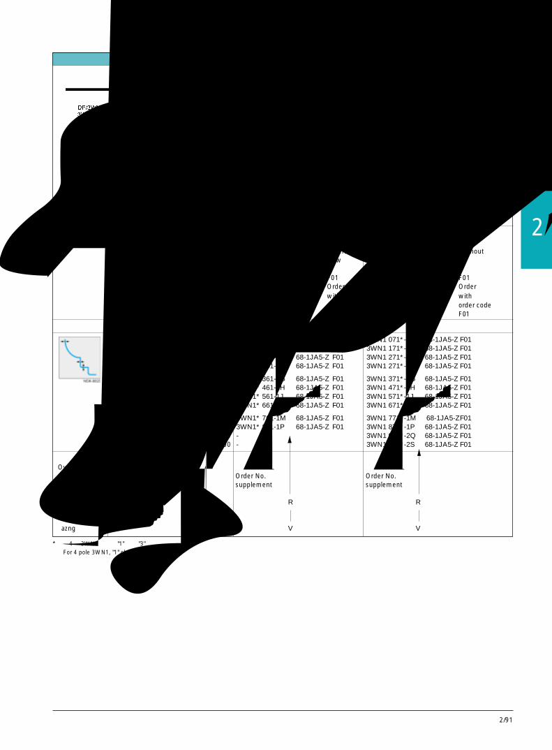
2/91
2
选型和订货参数
具有通讯能力的 3WN1系列断路器,至 6300A,3极Communication-Capable 3WN1 Circuit-Breakers, up to 6300A, 3-pole
Selection and ordering data
额定工作电压Ue 至AC 690V 通过 PROFIBUS 实现的功能:至AC 500/690V时的额定极限短路分断能力Icu: ● 传送相电流(框架尺寸等级 I,II)至 80/60kA ● 传送脱扣信号(框架尺寸等级 III,IV)至 100/80kA ● 传送报警信号带电动机操作机构 AC 220 至 250V ● 传送运行状态信号(断路器处于合/分闸状态)带分励脱扣器 AC 220 至 240V ● 传送使断路器合/分闸指令带辅助触头(2NO + 2NC)
Rated operational voltage Ue
up to AC 690 VRated ultimate short-circuit breakingcapacity Icu up to AC 500/690 V:Size I, II up to 80/60 kASize III, IV up to 100/80 kAWith motorized operating mechanism AC 220up to 250 VWith shunt release AC 220 to 240VWith auxiliary switch (2 NO + 2 NC)
Functions with PROFIBUS● transmission of phase current● tripped signal● alarm signal● operational status signal (circuit-breaker on/
off)● circuit-breaker on/off command
过电流脱扣器 通过 PROFIBUS 实现的功能: 订货号 订货号Overcurrent Functions with PROFIBUS 补充 补充releases 见下表接口 Order No. Order No.
see Interfaces supplement supplement
“azn” R R
“azng” V V
尺寸 额定电流In 电流整定 固定式断路器, 主回路上、下进出线均为 抽屉式断路器,不带导向框架等级 =电流互感 范围Ir 垂直连接铜排Size 器额定电 Fixed-mounted circuit-breakers Vertical Withdrawable circuit-breakers without
流In connecting bars, above and below guide frameRated Current 带订货码 带订货码current In setting 订货号 F01 订货号 F01=transformer range Ir Order No. Order Order No. Orderrated current with withIn order code order codeA A F01 F01
I/1 630 252-630 3WN1* 061-1D □ 68-1JA5-Z F01 3WN1 071*-1D□ 68-1JA5-Z F01I/1 800 320-800 3WN1* 161-1E □ 68-1JA5-Z F01 3WN1 171*-1E□ 68-1JA5-Z F01I/1 1000 400-1000 3WN1* 261-1F □ 68-1JA5-Z F01 3WN1 271*-1F □ 68-1JA5-Z F01I/1 1250 500-1250 3WN1* 261-1G □ 68-1JA5-Z F01 3WN1 271*-1G□ 68-1JA5-Z F01
I/2 1250 500-1250 3WN1* 361-1G □ 68-1JA5-Z F01 3WN1 371*-1G□ 68-1JA5-Z F01I/2 1600 640-1600 3WN1* 461-1H □ 68-1JA5-Z F01 3WN1 471*-1H□ 68-1JA5-Z F01II 2000 800-2000 3WN1* 561-1J □ 68-1JA5-Z F01 3WN1 571*-1J □ 68-1JA5-Z F01II 2500 1000-2500 3WN1* 661-1K □ 68-1JA5-Z F01 3WN1 671*-1K□ 68-1JA5-Z F01
III/1 3200 1260-3200 3WN1* 761-1M□ 68-1JA5-Z F01 3WN1 771*-1M□ 68-1JA5-ZF01III/1 4000 1600-4000 3WN1* 831-1P □ 68-1JA5-Z F01 3WN1 871*-1P□ 68-1JA5-Z F01IV 5000 2000-5000 - 3WN1 971*-2Q□ 68-1JA5-Z F01IV 6300 2520-6300 - 3WN1 971*-2S□ 68-1JA5-Z F01
断路器装有过电流脱扣器 / Circuit-breakers with overcurrent releases
*:对 4 极 3WN1,相应 "1" 改为 "3"For 4 pole 3WN1, "1" change to "3"

2/92
具有通讯能力的 3VL系列断路器,至 800A,用于固定式安装,3极Communication-Capable 3VL Circuit-Breakers, up to 800A, for Fixed Mounting, 3-pole
项目 订货号Item Order No.
系统手册 E20001-P285-A644-V13VL、3WN6、3WN1/3WS1 断路器与 PROFIBUS-DP 相连的通讯界面介绍System manualCommunication interface for 3VL, 3WN6, 3WN1/3WS1 circuit-breakers to PROFIBUS-DP
SIMOCODE-DP 系统手册System manual for SIMOCODE-DP德文版,包括系统数据文件 3UF57 00-0AA00-0German including system data files英文版,包括系统数据文件 3UF57 00-0AA00-1English including system data files
PROFIBUS 连接器 6ES7 972-0BB20-0XA0用于将接口接至 PROFIBUSPROFIBUS connectorfor connecting the interface to PROFIBUS
连接电缆 3RW29 20-1DA00用于通过 SIMOCODE-DP 接口与 PC 相通讯,长度 5mConnecting cablefor communication with a PC via the SIMOCODE-DP interface, length 5m
参数设置软件 Win-SIMOCODE-DP 3RK1 803-2FA02-0DA0基于 Windows 95 或 Windows NT 的软件,用于通过SIMOCODE-DP 系统接口对 SIMOCODE-DP 进行参数设置,控制,诊断和试验,包括用于 3VL 的参数文件。德语/英语可选择。(不带连接电缆)Parameterization software Win-SIMOCODE-DPSoftware based on Windows 95 or Windows NT for parameterization, control, diagnosisand testing of SIMOCODE-DP via the SIMOCODE-DP interface,German/English selectable (without connecting cable) including parameter file for 3VL
附件(必备的) Accessories (necessary)

2/93
2
推荐采用的附加功能
具有通讯能力的 3WN6系列断路器,至 3200A,3极Communication-Capable 3WN6 Circuit-Breakers, up to 3200A, 3-pole
Further versions (recommended)
当选用具有该附加功能的断路器时,应在完整的订货号后加上 “-Z” 和订货代号 “K01”When ordering circuit-breakers in the above versions, the complete Order No. must be supplemented with "-Z" and the order code "K01"
订货号Order No.3WN6..1-7..51-1BA1-Z及附加订货码and with additional code□□□+...+...
用于具有通讯能力的断路器For communication-capable circuit-breakers only
具有脱扣后自动机械复位功能 K01With automatic mechanical reset after tripping
(如不带附加功能 K01,断路器故障脱扣后必须按断路器上的红色复位按钮手动复位)(Without the additional function K01 the switch must be reset manually using the red RESET button on the switch after tripping)
附件 Accessories
用于具有通讯能力的 3WN6 断路器For ordering communication-capable 3WN6 circuit-breakers
订货号 /Order No.
系统手册 E20001-P285-A644-V1-76003VL,3WN6,3WN1/3WS1 断路器与 PROFIBUS-DP 相连的通讯界面介绍System manualCommunication interfacefor 3VL, 3WN6, 3WN1/3WS1 circuit-breakers to PROFIBUS-DP
DP/3WN6 接口 3RK1000-0JC80-0BA1每台具有通讯能力的断路器需要一个(包括有 GSD 文件的 31/2" 软盘)DP/3WN6 interfacerequired once only per communication-capable circuit-breaker(including 31/2" disk with type or GSD file)
DC24V 电源 如 4AV2 系列,请参见有关样本用于 DP/3WN6 接口的供电DC 24 V power supply e.g. 4AV2for DP/3WN6 interface
PROFIBUS 连接器 6ES7972-0BB20-0XA0将接口联接至 PROFIBUSPROFIBUS connectorfor connecting the interface to PROFIBUS.
软件模块 3RK1800-0AA00-0AA0推荐用于 SIMATIC S5 和 S7;用于通讯控制的编程工具,31/2" 软盘Software modulerecommended for SIMATIC S5 and S7;programming aid for communication control, 31/2" disks
有关 3WN6 通讯的描述,见第 2/87 页For further communication-capable 3WN6 circuit-breakers see also description on page 2/87.

2/94
选型和订货数据 Selection and ordering data
SICAM LCC 图形化操作软件 /SICAM LCC Visualization SoftwareSICAM LCC 6MD54 02-0BA00-1AA0该软件用于针对采用 PROFIBUS-DP 通讯的电器设备,在电脑屏幕上生成一个标准化的图形界面和显示所有重要的信息,包括 SICAM Valpro 可分析测量值。SICAM LCC 可用于包含 3VL、3WN6、3WN1、3WS1 和 SIMOCODE-DP3UF5 的配电保护和控制系统。Software for creating a standard visualization screen and display of all-important information from devicesconnected to PROFIBUS-DP, incl. SICAM Valpro for analysis of stored readings, SICAM LCC is used to display3VL, 3WN6, 3WN1, 3WS1 and SIMOCODE-DP 3UF5.从 SICAM LCC 中可调用 Win-SIMOCODE-DP 和 Win3WN6.Using a suitably installed communication processor, Win-SIMOCODE-DP/Professional and Win3WN6 can alsobe called up with SICAM LCC.用户可根据需要扩展该软件的功能。/Customized expansion features are possible.对 PC 机的要求 /PC-requirements: INTEL Pentium 133MHz
Windows NT4.0RAM 64MB硬盘可用空间 /Free space on hard disk 2GB图形适配器 /Graphics adapter SVGA监视器 /Monitor 1024 x 768PU/PC 接口要求:/PU/PC interface requirements:Win-SIMOCODE-DP 专业版 /Win-SIMOCODE-DP/ProfessionalCP5412(A2)及相应软件 /CP5412 (A2) with appropriate software供货范围:带授权软盘的 CD-ROM,德语 / 英语可选,包括 CD-ROM 手册和在线帮助,用户使用证。Mode of delivery:CD-ROM with authoring disks, German/English (switchable) incl. CD-ROM manual and Online Help, single-user licenseSICAM LCC 手册 / SICAM LCC manual 英语 /English E50417-H8976-C030
德语 /German E50417-H8900-C030SICAM Valpro 手册 / SICAM Valpro manual 英语 /English E50417-H8976-C020
德语 /German E50417-H8900-C020
项目 / Item 订货号 / Order No.
Win3WN6 Professional V1.0(专业版) 3WX3647-6AC00通过 PROFIBUS-DP 或 RS232 进行参数设置,操作控制,监控,试验,包括在线帮助,德语 / 英语可选。主机控制系统:SIMATIC S5, S7, 与 PROFIBUS-DP兼容的 PC 机主机系统(RS232):笔记本电脑或个人电脑供货内容:光盘,3.5" 软盘,联接至 RS232 口的匹配器和电缆线Parameterization, operator control, monitoring, testingvia PROFIBUS-DP or RS232, incl. online help, German/English selectable.Target master systems: SIMATIC S5, S7, PROFIBUS-DP compaible PCTarget system (RS232): Laptop or PCScope of supply: CD, 3.5" disk, interface cable and network adapter for RS232.
Win3WN6 Smart V1.0(简易版) 3WX3647-6AB00通过 RS232 进行参数设置,操作控制,监控,试验,包括在线帮助,德语 / 英语可选。主机控制系统:SIMATIC S5, S7, 与 PROFIBUS-DP兼容的 PC 机主机系统:笔记本电脑或个人电脑供货内容:光盘,联接至 RS232 口的匹配器和电缆线Parameterization, operator control, monitoring, testing via RS232incl. online help, German / English selectableTarget system: Laptop or PCScope of supply: CD, interface cable and network adapter for RS232.
电源组 3WX3647-6JA02Power pack如采用 RS232 口通讯,且断路器无 DC24V 电源输出端子需采用此电源组required for RS232 communication, if the circuit-breaker has no DC 24V supply
简易版升级至专业版 V1.0 3WX3647-6AD00Smart Upgrade to Professional V1.0用于将 Win3WN6 简易版升级至 Win3WN6 专业版的软件包供货内容:3.5" 软盘Software package for upgrading from Win 3WN6 Smart to Win 3WN6 Professional Scope of supply:3.5 " disk
Win3WN6示范版 3WX3647-6AA00Win-3WN6 Demo帮助了解 Win3WN6 的操作屏幕,无通讯功能,德语 / 英语可选供货内容:光盘provides navigation help through Win-3WN6 screens, without communication function.Scope of supply: CD, incl. electronic manual, online help, German / English selectable.
具有通讯能力的断路器 3WN6,至 3200ACommunication-Capable 3WN6 Circuit-Breakers, up to 3200A
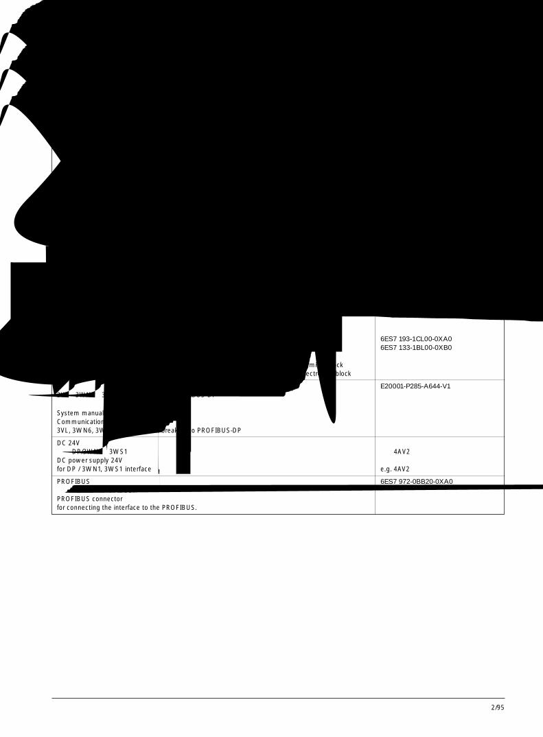
2/95
2
具有通讯能力的 3WN1系列断路器,至 6300A,3极Communication-Capable 3WN1 Circuit-Breakers, up to 6300A, 3-pole
用于 3WN1和 /或 3WS1的附件 Accessories for 3WN1 and/or 3WS1
导向框架 订货号Guide frame Order
包含用于通讯的生产厂安装的连接电缆(SubD口, 9极) 带订货码Including factory-installed connecting cable R39(SubD, 9-pole) for communication Order only with
带 T 形连接件 尺寸等级 用于断路器 order code R39
With T-shaped connecting pieces Sizes for circuit-breakers无断路器位置远距离信号发送开关 I 3WN1 0 to 3WN1 4 3WX31 83-8CA00-1EA3-Z R39without remote signaling of the circuit-breaker position II 3WN1 5 and 3WN1 6 3WX31 83-8DA00-1EA3-Z R39带活动延伸导轨 III 3WN1 7 and 3WN1 8 3WX31 83-8GA00-1EA3-Z R39with hinged rails IV 3WN1 9 to 5000 A 3WX31 83-8HA00-1EA3-Z R39无挡板 IV 3WN1 9 to 6300 A 3WX31 83-8UA00-1EA3-Z R39without shutter4 个辅助接线端子块4 auxiliary connectors无防止柜门打开或断路器移动的锁具without locking fixtures to preventthe cubicle door being opened or the circuit-breaker being moved.
接口(每台断路器至少需要 1 或 2 )Interfaces (at least 1 or 2 are required for each circuit-breaker)1 DP/3WN1,3WS1 用于: 3RK1 002-0BB00-0AA0
● 传送相电流IL1, IL2, IL3, ILmax
● 传送脱扣信号● 传送报警信号
1 DP/3WN1, 3WS1 for● transmission of the phase currents IL1, IL2, IL3, ILmax
● tripped signals● alarm signals
2 ET200L(16DI,16DO)用于:● 传送断路器工作状态(如断路器已合/分闸状态) 接线端子模块 6ES7 193-1CL00-0XA0● 传送使断路器合/分闸指令 电子模块 6ES7 133-1BL00-0XB0
2 ET200L (16 DI, 16 DO) for:● operational status signal (e.g. circuit-breaker on/off) Terminal block● circuit-breaker on/off command Electronics block
系统手册 E20001-P285-A644-V13VL,3WN6,3WN1/3WS1 断路器与 PROFIBUS-DP相连的通讯界面介绍System manualCommunication interface for3VL, 3WN6, 3WN1 / 3WS1 circuit-breakers to PROFIBUS-DP
DC 24V 电源用于 DP/3WN1,3WS1 接口的供电 如:4AV2 系统DC power supply 24Vfor DP / 3WN1, 3WS1 interface e.g. 4AV2
PROFIBUS 连接器 6ES7 972-0BB20-0XA0将接口联接至 PROFIBUS.PROFIBUS connectorfor connecting the interface to the PROFIBUS.
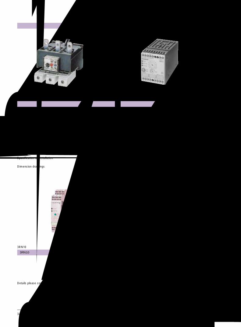
热过载继电器 Thermally delayed overload relays
说明 3/1Description选型与订货数据 3/1Selection and ordering data附件 3/5Accessories技术数据 3/6Technical data内部接线图 3/10Internal connection diagrams安装使用说明 3/11Specification of installation外型及安装尺寸 3/12Dimension drawings
Switching Devices for Load FeedersOverload Relays
用于电动机的开关和装置过载继电器
页号3UA Page
3/0
CLASS 5 to CLASS 30
描述 3/16Description选型订货表 3/20Selection and odering data技术数据 3/22Technical data电路图 3/25Circuit diagrams外形尺寸,线路图 3/25Dimensions and circuit diagrams
页号3RB 12 Page
3RN10热敏马达保护装置 3RN10 Thermistor motor protection
页号3RN10 Page
详情请洽西门子办事处Details please contact Siemens Office
电子式热继电器 Solid state overload relays
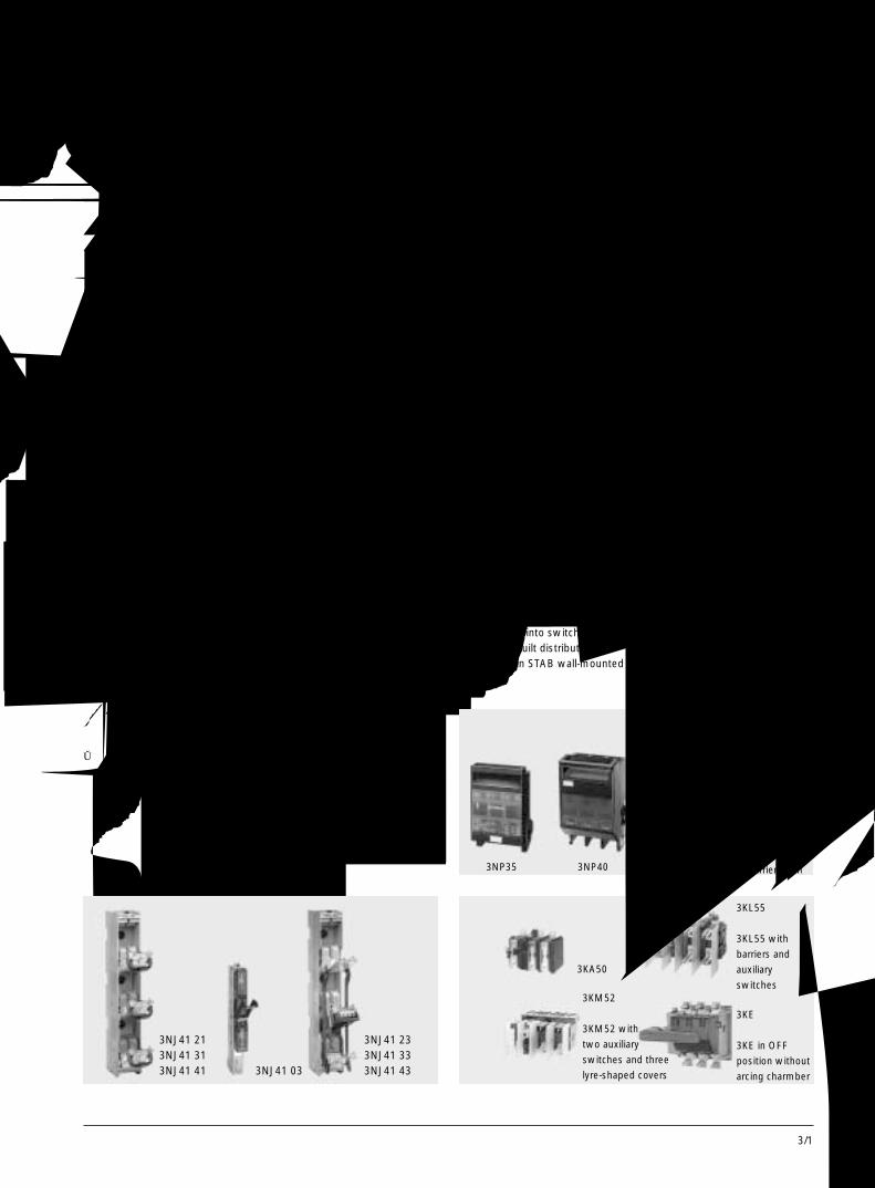
3/1
3
3K. 系列隔离开关3KL和3KM隔离开关设计成外
部安装熔断器的形式。3KA 隔离开关用隔离片替代熔断器,3KE 隔离开关具有动触头。这些触头由主触头和弧触头组成,触头更换方便。
与3KL隔离开关相比,3KM隔离开关在后面有一个隔离插头,最适合安装在带有垂直母排的马达控制中心(MCC)柜中。它们安装在插入式框架中,将插头插入柜中的框架即接通了母排。抽出抽屉单元,即形成一额外隔离空间。
3KL5、3KL6、3KM和 3KA隔离开关为三极。其中的一些型号能增加第四极。
当 3KL 和 3KM 隔离开关断开时,熔断器也随即断开。当3K 隔离开关断开时,都能用挂锁锁定。然而有些时候需要门操作机构( 用于3KL6和 3KE)或可锁定检查罩(用于3KE)。此机构有90º的操作角度,具有快速断开和闭合特性。
所有的 3K 系列隔离开关适合在任何气候下使用,符合IEC947-1、IEC947-3、和DIN VDE0660第 107部分的标准。根据DIN VDE 0113它们可用作主开关和“急停”开关。
3NP系列熔断器式隔离开关3NP熔断器式隔离开关能带负
载接通和断开电路。它们适合在任何气候下使用,符合 IEC947-1、IEC947-3、和DIN VDE0660第 107部分的标准。此外,3NP5熔断器式隔离开关符合 BS 5419 标准,也适合在船上使用。
依据使用的型号,3NP熔断器式隔离开关适合于表面安装和安装在开关柜以及工厂自制配电盘内,例如用在 STAB 壁挂式和 SIKUS 落地式配电盘内。或在SIPRO通用系统中,它们也能在不同的母线上安装。
3NP35 30 熔断器式隔离开关也能卡装在 35mm 标准安装导轨上。
熔断器和无熔断器式隔离开关Fusable and Non-Fusable Disconnectors
说明 Description
3NJ系列顺列熔断器式隔离开关3NJ41和3NJ56型单极和三极
顺列熔断器式隔离开关能安装在低压配电柜、变电站和电缆分配柜内。它们适合在任何气候下使用。
在断开位置具手背触摸防护(3NJ56 IP 00除外)。当熔断器座闭合后,所有顺列熔断器式隔离开关的防护等极为 IP 20。它们符合 IEC408、IEC947-3和DIN VDE 0660 第107 部分标准。符合 DIN 43620 第一部分标准的熔断器可以使用,但不允许使用连接片镀镍的熔断器。
3K. Switch DisconnectorsThe 3KL and 3KM switchdisconnectors are designed forexternally mounted fuses. Insteadof fuses, the 3KA disconnectorshave disconnecting links and the3KE disconnectors have movablecontacts. These contacts consistof main contacts and arcingcontacts with easily replaceableerosion contacts. If additionalfuses are to be used, these haveto be located separately.In contrast to 3KL disconnectors,the 3KM disconnectors have anisolating plug connector on therear side and are best suited forfitting in Motor Control Center(MCC) cubicles with a verticalconductor bar. They are installedin plug-in frames and contact withthe bars is established byinserting them into this frame inthe cubicle. By pulling out thewithdrawable unit, an additionalisolating distance is created.The 3KL5, 3KL6, 3KM and 3KAdisconnectors are 3-pole. Withsome types, a fourth pole can beadded.disconnectors are switched off,the fuses are dead. All 3K.disconnectors can be secured
with a padlock when they areswitched off. However, a door-coupling rotary mechanism issometimes necessary (with 3KL6,3KL7 and 3KE) or a lockableinspection mask (with 3KE).The mechanisms have anoperating angle of 90° and areequipped with high-speedopening and closing feature.All 3K. disconnectors are suitablefor use in any climate and complywith IEC 947-1, IEC 947-3 andDIN VDE 0660 Part 107. They canbe used as main switches andEMERGENCY STOP switches inaccordance with DIN VDE 0113.
3NP Fuse Switch Disconnectors3NP fuse switch disconnectorscan be safely used for all-polemaking and breaking of circuitsunder load.They are suitable for use in anyclimate and comply with standardIEC 947-1, IEC 947-3 and DIN VDE0660 Part 107. In addition, the3NP5 fuse switch disconnectorcomplies with BS 5419. It is alsosuitable for use on-board ship.Depending on the version used3NP fuse switch disconnectorsare suitable for surface mountingand for fitting into switchboardsand factory-built distributionboards e.g. in STAB wall-mounted
and SIKUS floor-mounteddistribution boards or in SIPROuniversal systems. They can alsobe fitted in different busbarsystems. They can also be fittedin different busbar systems.The 3NP35 30 fuse switchdisconnector can also be snappedonto 35 mm standard mountingrails.
3NJ In-Line Fuse SwitchDisconnectorsSingle-pole and three-pole in-linefuse switch disconnectors oftypes 3NJ41 and 3NJ56 aredesigned for installation in low-voltage distribution boards,substations and cable distributioncabinets.They are suitable for use in anyclimate.In an open position, they are safefrom touch by the back of thehand (exception 3NJ56: IP 00).When the fuse carriers areclosed, the degree of protectionfor all inline fuse switchdisconnectors is IP 20. Theycomply with the specifications ofIEC 408, IEC 947-3 and DIN VDE0660 Part 107. Fuse links to DIN43 620 Part 1 can be used -nickel-plated fuse blades are notpermissible.
3NJ41 213NJ41 313NJ41 41 3NJ41 03
3NJ41 233NJ41 333NJ41 43
3KM52 带两个辅助
开关和三个层形罩
3KM52 with
two auxiliary
switches and three
lyre-shaped covers
3KE 处于分断位
置没有灭弧罩
3KE in OFF
position without
arcing charmber
3KL55 带隔板和
辅助开关
3KL55 with
barriers and
auxiliary
switches
3NP35 3NP40 3NP52熔断器载体打开with fuse carrier open
3KA50
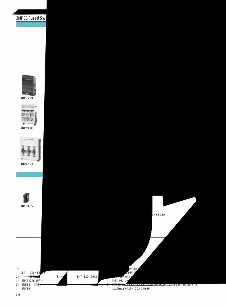
3/2
Selection and ordering data选型及订货数据
额定不间断电流Ratedunin-terruptedcurrentIu
A
导线连接(在两端)Conductor connection(on both sides)
端子类型Type ofterminal
导线截面for conductorcross-sectionmm2
适用熔断器DIN 43 620For fuse linksacc. to DIN43 620
规格Size
适用隔离体Forisolatinglinks
规格Size
大约重量Weightapprox.kg
防护等级 IP 00Degree of protection IP 00
不带熔断器 without fuse links不带隔离体 without isolating links带有螺丝端子 with terminal screws
订货号Order No.
用于表面安装和在开关柜内安装For surface mounting and for installation
1602) SIGUT 1.5~50 000 1) 00 3NP35 30-0CH00 0.553盒式接线端子SIGUT boxterminal
1602) 盒式接线端子 1.5~50 000 1) 000 3NP40 10-0CH01 0.581Box terminal
160 扁平垫圈连接 ~2x70(M8) 00 00 3NP40 70-0CA01 0.700Flat padconnection盒式接线端子 2.5~70 3NP40 70-0CH01 0.800Box terminal
250 扁平垫圈连接 ~150(M10) 1 and 0 1 and 0 3NP42 70-0CA01 2.300Flat padconnection
400 扁平垫圈连接 ~240(M10) 2 and 1 2 and 1 3NP43 70-0CA01 3.400Flat padconnection
630 扁平垫圈连接 ~2x240 3 and 2 3 and 2 3NP44 70-0CA01 4.600Flat pad (M12)connection
3NP35 30
3NP40 10
3NP42 70
3NP35 (至 160A) 和 3NP4 (至 630A) 熔断器式隔离开关3NP35 Fused Switch Disconnectors up to 160A and 3NP4 up to 630A
附件 Accessories
用于 3NP40 的附件也可用于 3NP35 用于熔断器式隔离开关 附件订货号 大约重量Accessories for 3NP40 can also be For fuse switch disconnectors Accessories Order No. Weight approx.used for 3NP35 kg
1CO 辅助开关 3NP40 1 ~ 3NP44 3NY3 035 0.005带自攻螺钉Auxiliary switch 1COwith self-cutting screws
1CO 辅助开关 3NP40 1 ~ 3NP44 3NY3 030适用于电子线路带自攻螺钉Auxiliary switch 1CO solid-statecompatible,with self-cutting screws
3NY30 35
1) 对应于最大宽度为21mm 规格为00的熔断器 (符合 IEC 69 269-2-1 和 DIN 43 620)。
2) 仅为 125/160A,采用宽度为21mm的熔断器3NY1822(125A)和3NY1824(160A)。
3) 3NP35 和 3NP4 熔断器式隔离开关可加装一对辅助触头(1CO),3NY30。
1) Corresponds to size 00 with a maximum width of 21mm (acc. to IEC 69269-2-1 and DIN 43 620).
2) 125/160A only possible with 3NY1822(125A) and 3NY1824(160A) fuselinks with a width of 21mm.
3) 3NP35 and 3NP4 fuse switch disconnectors can be retrofitted withauxiliary switch (1CO), 3NY30.
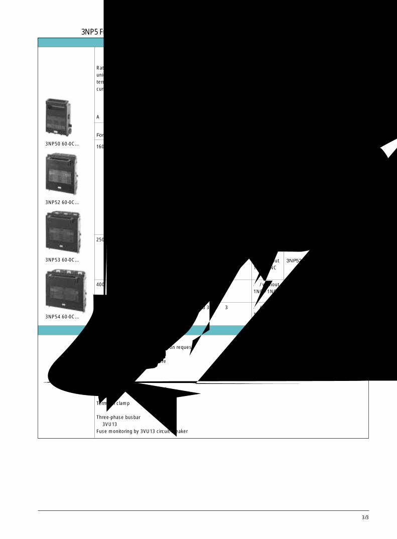
3/3
3
Selection and ordering data选型及订货数据
额定不间断电流Ratedunin-terruptedcurrent Iu
A
导线连接(在两端)Conductor connection(on both sides)
连接Connection
导线截面for conductorcross-sectionmm2
熔断器
DIN 43 620
For fuselinks acc. toDIN 43 620
规格Size
隔离体
Forisolationlinks
规格Size
隔离开关辅助触头Auxiliarycontacts ofthe switchdisconnector
类型Type
防护等级 IP 00Degree of protection IP 00
无熔断器 without fuse links无隔离体 without isolating links带有螺丝端子 with terminal screws
订货号 大约重量Order No. Weight
approx kg
用于表面安装和开关柜内安装For surface mounting and for installation in switchboards
160 扁平垫圈连接 2.5-150 00 00 无 / without 3NP50 60-0CA00 1.5Flat pad 1NO+1NC -0CA10 1.5connection夹接 00 00 无 / without 3NP50 60-0CB00 1.6Clamp 1NO+1NC -0CB10 1.6connection
250 扁平垫圈连接 6-150 1 1 无 / without 3NP52 60-0CA00 4.8Flat pad 1NO+1NC -0CA10 4.9connection夹接 35-120 1 1 无 / without 3NP52 60-0CB00 5Clamp 1NO+1NC -0CB10 5.1connection
400 扁平垫圈连接 6-240 1 and 2 2 无 / without 3NP53 60-0CA00 5.8Flat pad 1NO+1NC -0CA10 5.9connection
630 扁平垫圈连接 6-2 × 240 2 and 3 3 无 / without 3NP54 60-0CA00 7.1Flat pad 1NO+1NC -0CA10 7.2connection
1 根导线2.5-50 或2 根导线1 × 2.5-501 × 2.5-351 conductor2.5 to 50 or2 conductors1 × 2.5-501 × 2.5-35
3NP50 60-0C...
3NP52 60-0C...
3NP53 60-0C...
3NP54 60-0C...
Accessories附件下列附件可供选择Further accessories are available on request塑模防护框架Moulded-plastic masking frame安装配件Installation kit端子罩,辅助触头Terminal covers, Auxiliary switch夹紧式端子Terminal clamp三相母排Three-phase busbar用 3VU13 断路器进行熔断器监控Fuse monitoring by 3VU13 circuit-breaker
3NP5熔断器式隔离开关 (至 630A),全封闭,快速闭合3NP5 Fused Switch Disconnectors up to 630A, Fully Compartmented, with High-Speed Closing
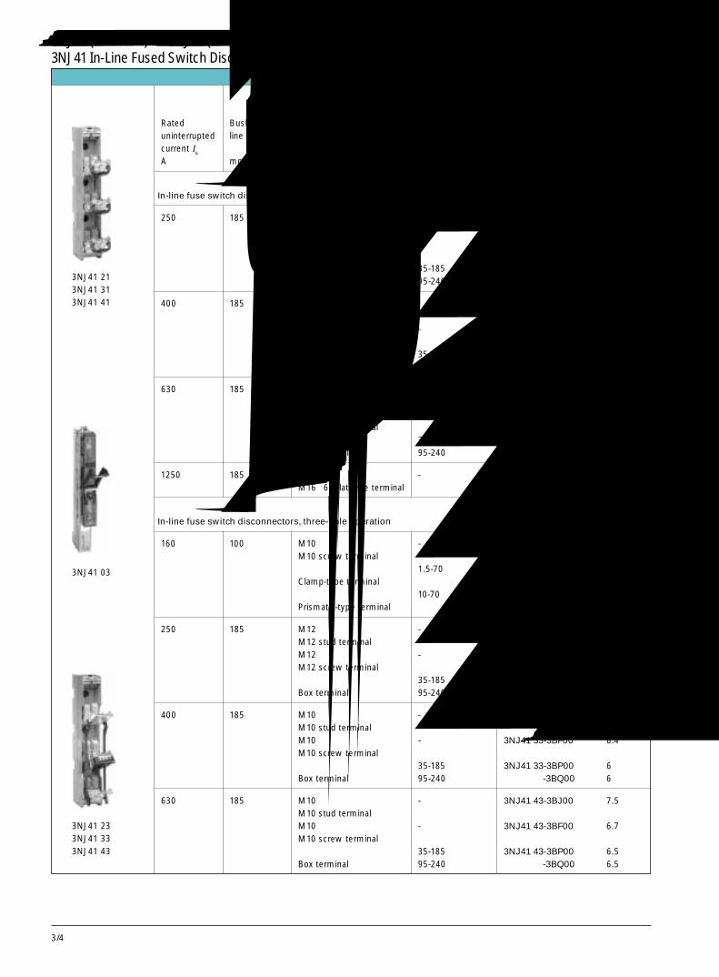
3/4
Selection and ordering data选型及订货数据
额定不间断电流Rateduninterruptedcurrent Iu
A
订货号 大约重量Order No. Weight
approx
kg
母排中心线间距Busbar centre-line spacing
mm
端子类型(螺丝端子 / 夹式端子,包括在供货范围内)Terminal type (screwterminals/clamp-typeterminals incl. in the scopeof supply)
导线截面For conductorcross-section
mm2
顺列熔断器式隔离开关,单级操作In-line fuse switch disconnectors, single-pole operation
250 185 M10 短柱式端子 - 3NJ41 21-3BJ00 5.8M10 stud terminalM10 螺丝端子 - 3NJ41 21-3BF00 5.8M10 screw terminal盒式端子 35-185 3NJ41 21-3BP00 6Box terminal 95-240 -3BQ00 6
400 185 M12 短柱式端子 - 3NJ41 31-3BJ00 6.1M12 stud terminalM12 螺丝端子 - 3NJ41 31-3BF00 6M12 screw terminal盒式端子 35-185 3NJ41 31-3BP00 6Box terminal 95-240 -3BQ00 6
630 185 M10 短柱式端子 - 3NJ41 41-3BJ00 6.8M10 stud terminalM10 螺丝端子 - 3NJ41 41-3BF00 6.3M10 screw terminal盒式端子 35-185 3NJ41 41-3BP00 6.5Box terminal 95-240 -3BQ00 6.5
1250 185 M16×60 扁平式端子 - 3NJ56 43-0BB00 30M16×60 flat-type terminal
顺列熔断器式隔离开关,三级操作In-line fuse switch disconnectors, three-pole operation
160 100 M10 螺丝端子 - 3NJ41 03-3BF00 1.4M10 screw terminal夹式端子 1.5-70 3NJ41 03-3BK00 1.4Clamp-type terminal棱柱式端子 10-70 3NJ41 03-3BL00 1.5Prismatic-type terminal
250 185 M12 短柱式端子 - 3NJ41 23-3BJ00 6.5M12 stud terminalM12 螺丝端子 - 3NJ41 23-3BF00 6.2M12 screw terminal盒式端子 35-185 3NJ41 23-3BP00 6Box terminal 95-240 -3BQ00 6
400 185 M10 短柱式端子 - 3NJ41 33-3BJ00 6.8M10 stud terminalM10 螺丝端子 - 3NJ41 33-3BF00 6.4M10 screw terminal盒式端子 35-185 3NJ41 33-3BP00 6Box terminal 95-240 -3BQ00 6
630 185 M10 短柱式端子 - 3NJ41 43-3BJ00 7.5M10 stud terminalM10 螺丝端子 - 3NJ41 43-3BF00 6.7M10 screw terminal盒式端子 35-185 3NJ41 43-3BP00 6.5Box terminal 95-240 -3BQ00 6.5
3NJ41 233NJ41 333NJ41 43
3NJ41 03
3NJ41 213NJ41 313NJ41 41
3NJ41 (至 1000A) 和 3NJ56 (至 1250A) 顺列熔断器式隔离开关3NJ41 In-Line Fused Switch Disconnectors up to 1000A and 3NJ56 up to 1250A
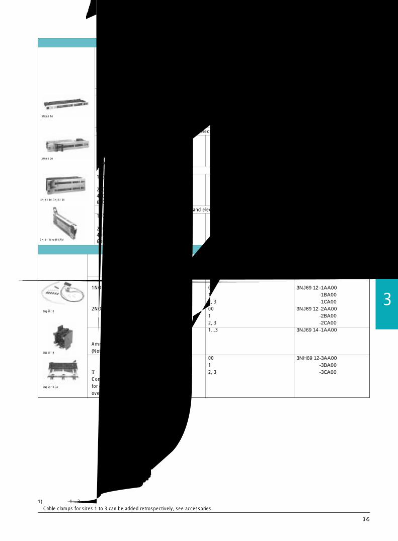
3/5
3
订货与选型数据 Selection and ordering data
3NJ6插入式熔丝隔离开关3NJ6 Plug-in Switch Disconnectors with Fuses
额定电流 所用溶丝符合 DIN 43 620 导体连接方式 (连接插头中心为 185mm) 订货号 重量Rated For fuse links acc. to Conductor connection (center-to- Order No. Weightuninterrupted DIN 43 620 center distance of the plug approxcurrent In at contacts 185mm)AC500VA 规格 / Size kg
单断点 / With single break160 00 螺丝端子 / Stud terminal M8 3NJ61 10-3EB01-0BB0 4.0
电缆夹端子 / Cable clamp terminal 3NJ61 10-3EB11-0BB0 4.1250 1 螺丝端子 / Stud terminal M12 3NJ61 20-3EB01-0BB0 6.9400 2 螺丝端子 / Stud terminal M12 3NJ61 40-3EB01-0BB0 16.5630 3 螺丝端子 / Stud terminal M12 3NJ61 60-3EB01-0BB0 16.8
单断点带电子熔丝监视 / With single break and electronic fuse monitoring (EFM)160 00 螺丝端子 / Stud terminal M8 3NJ61 10-3EM01-0BB0 4.0
电缆夹端子 / Cable clamp terminal 3NJ61 10-3EM11-0BB0 4.1250 1 螺丝端子 / Stud terminal M12 3NJ61 20-3EM01-0BB0 6.9400 2 螺丝端子 / Stud terminal M12 3NJ61 40-3EM01-0BB0 16.5630 3 螺丝端子 / Stud terminal M12 3NJ61 60-3EM01-0BB0 16.8
双断点 / With double break160 00 螺丝端子 / Stud terminal M8
电缆夹端子 / Cable clamp terminal 3NJ61 10-3MA11-0BB0 4.1250 1 螺丝端子 / Stud terminal M12 3NJ61 20-3MA01-0BB0400 2 螺丝端子 / Stud terminal M12 3NJ61 40-3MA01-0BB0630 3 螺丝端子 / Stud terminal M12 3NJ61 60-3MA01-0BB0双断点带电子熔丝监视 / With double break and electronic fuse monitoring (EFM)160 00 螺丝端子 / Stud terminal M8
电缆夹端子 / Cable clamp terminal (10-95mm 1) 3NJ61 10-3MB01-0BB0 4.1250 1 螺丝端子 / Stud terminal M12 3NJ61 20-3MB01-0BB0400 2 螺丝端子 / Stud terminal M12 3NJ61 40-3MB01-0BB0630 3 螺丝端子 / Stud terminal M12 3NJ61 60-3MB01-0BB0
Accessories附件用于规格 NH 的隔离开关 订货号For disconnectors Order No.sizes NH
辅助触点 / Auxiliary switch1NO+1NC 00 3NJ69 12 -1AA00
1 -1BA002, 3 -1CA00
2NO+2NC 00 3NJ69 12 -2AA001 -2BA002, 3 -2CA00
电流表固定支架 1...3 3NJ69 14 -1AA00规格为 00 时不需要Ammeter fastening frame(Not necessary for size 00)端子延伸件 00 3NH69 12-3AA00用于延伸黑色夹子式接线端子 1 -3BA00总深度 200mm 2, 3 -3CA00Contact extensionsfor extending the back clamp-type terminalsoverall depth 200mm
1) 改造时可加 1…3 号线夹,见附件Cable clamps for sizes 1 to 3 can be added retrospectively, see accessories.
3NJ69 12
3NJ69 14
3NJ69 11-3A
3NJ61 10
3NJ61 20
3NJ61 40, 3NJ61 60
3NJ61 10 with EFM
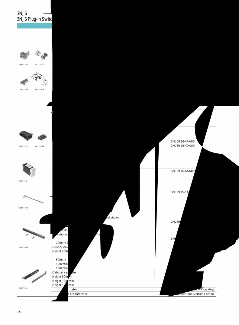
3/6
3NJ6插入式熔丝隔离开关,附件3NJ6 Plug-in Switch Disconnectors with Fuses, Accessories
所适用隔离开关的 LV HRC 规格 订货号For disconnectors size LV HRC Order No.
导线夹单夹 1 3NJ69 11-1BA00双夹 1 -2BA00双夹 2, 3 3NJ69 11-2CA00Cable clampsSingle clampDouble clampDouble clamp端子盖 00 3NJ69 13 -1AA00Terminal covers 1, 透明 /see through -1BA00
2, 3 -1CA001, 3 橡胶 /rubbe sleeves -2BA00
中央故障指示器 --...3 3NJ69 16 -5CA00用于带 EFM 的隔离开关,最多联 50 个开关Centralized fault indicatorfor disconnectors with EFM up to 50disconnectors in parallel拔出工具 0...3 3NJ69 16-4BA00可从开关连接件柜中拔出Pulling out toolfor pulling the switch connectors out of the cabinet盖板(带安装附件)有通风槽高 50mm (塑料) 3NJ69 16-4AA00高 100mm (塑料) 3NJ69 16-4DA00Blank cover(incl. fixing material)with ventilation slotsHeight 50mm (plastic)Height 100mm (plastic)导轨 00...3 3NJ69 16-6AA00用于保证现场安装可靠,或帮助安装,深 200mmGuide railsfor secure mounting on site or as an aid tomounting, depth 200mm分隔板 3NJ69 15-1AA00(1 套 = 2 件,上,下)用于柜内额外的间隔,可装于任何柜中Section divider(1 set = 2 items, above and below)for extra unit sectionfor installation of any contralgear and contral station间隔门 3NJ69 15-4AA00用于额外的间隔,高 100mmSection doorfor extra unit section, height 100mm母排盖板 3NH69 16-4EA00高 200mm IP 20Busbar coveringsHeight 200mm, IP 20柜体卡式组件高 500mm 3NJ69 16-7AA00高 1000mm 3NJ69 16-7BA00高 1500mm 3NJ69 16-7CA00Cabinet cassetteHeight 500mmHeight 1000mmHeight 1500mm电流表 / Ammeter 见MP样本 / See MP catalog
电流互感器 / Transformer 请向西门子公司咨询 / Please contact Siemens office
3NJ69 13-1C
3NJ69 16-6
3NJ69 16-4B
3NJ69 16-5
3NJ69 16-4A
3NJ69 13-2B
3NJ69 13-1A 3NJ69 13-1B
3NJ69 11-2B 3NJ69 11-2C
订货与选型数据 Selection and ordering data
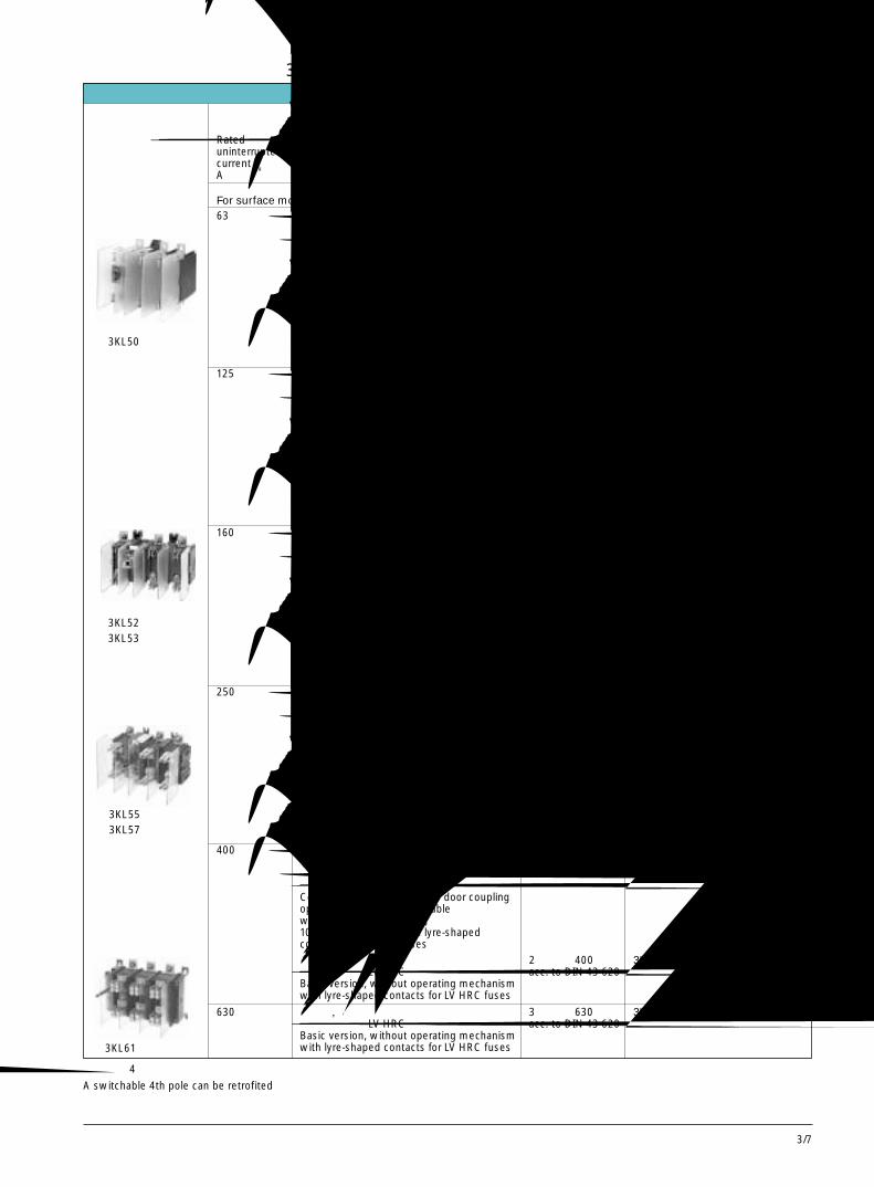
3/7
3
Selection and ordering data选型及订货数据
3KL5 (至 400A) 和 3KL6 (至 630A) 带熔断器的隔离开关,三级3KL5 Switch Disconnectors with Fuses up to 400A and 3KL6 up to 630A, 3-pole
额定不间断电流Rateduninterruptedcurrent IuA
订货号 大约重量Order No. Weight
approx
kg
类型 Version防护等级 IP 00 Degree of protection IP 00无辅助触头 without auxiliary contacts无熔断器 without fuse links带有螺丝端子 with terminal screws带有隔板 with barriers
所用熔断器For fuse links规格 额定电流Size Rated
currentA
63 完整型,带有 8UC6 门操作机构 00 63 3KL50 30-1EB00 1.15可用挂锁锁定 acc. to DIN 43 620黑色旋钮,6mm 方轴带有用于安装 LV HRC 熔断器的层形触头Complete version with 8UC6 door couplingoperating mechanism, lockablewith padlocks, black knob,6mm square shaft, with lyre-shapedcontacts for LV HRC fuses
基本型,无操作机构 00 63 3KL50 30-1AB00 0.85带有用于安装 LV HRC 熔断器的层形触头 acc. to DIN 43 620Basic version, without operating mechanismwith lyre-shaped contacts for LV HRC fuses
用于表面安装和开关柜内安装For surface mounting and for installation in switchboards
125 完整型,带有 8UC6 门操作机构 00 160 3KL52 30-1EB00 2.56可用挂锁锁定 acc. to DIN 43 620黑色旋钮,6mm 方轴带有用于安装 LV HRC 熔断器的层形触头Complete version with 8UC6 door couplingoperating mechanism, lockablewith padlocks, black knob,6mm square shaft, with lyre-shapedcontacts for LV HRC fuses
基本型,无操作机构 00 160 3KL52 30-1AB00 2.2带有用于安装 LV HRC 熔断器的层形触头 acc. to DIN 43 620Basic version, without operating mechanismwith lyre-shaped contacts for LV HRC fuses
160 完整型,带有 8UC6 门操作机构 00 160 3KL53 30-1EB00 2.56可用挂锁锁定 acc. to DIN 43 620黑色旋钮,8mm 方轴带有用于安装 LV HRC 熔断器的层形触头Complete version with 8UC6 door couplingoperating mechanism, lockablewith padlocks, black knob,8mm square shaft, with lyre-shapedcontacts for LV HRC fuses
基本型,无操作机构 00 160 3KL53 30-1AB00 2.2带有用于安装 LV HRC 熔断器的层形触头 acc. to DIN 43 620Basic version, without operating mechanismwith lyre-shaped contacts for LV HRC fuses
3KL50
3KL523KL53
250 完整型,带有 8UC6 门操作机构 1 and 2 400 3KL55 30-1EB00 5.4可用挂锁锁定 acc. to DIN 43 620黑色旋钮,10mm 方轴带有用于安装 LV HRC 熔断器的层形触头Complete version with 8UC6 door couplingoperating mechanism, lockablewith padlocks, black knob,10mm square shaft, with lyre-shapedcontacts for LV HRC fuses
基本型,无操作机构 1 and 2 400 3KL55 30-1AB00 4.5带有用于安装 LV HRC 熔断器的层形触头 acc. to DIN 43 620Basic version, without operating mechanismwith lyre-shaped contacts for LV HRC fuses
400 完整型,带有 8UC6 门操作机构 2 400 3KL57 30-1EB00 5.7可用挂锁锁定 acc. to DIN 43 620黑色旋钮,10mm 方轴带有用于安装 LV HRC 熔断器的层形触头Complete version with 8UC6 door couplingoperating mechanism, lockablewith padlocks, black knob,10mm square shaft, with lyre-shapedcontacts for LV HRC fuses
基本型,无操作机构 2 400 3KL57 30-1AB00 4.8带有用于安装 LV HRC 熔断器的层形触头 acc. to DIN 43 620Basic version, without operating mechanismwith lyre-shaped contacts for LV HRC fuses
3KL553KL57
630 基本型,无操作机构 3 630 3KL61 30-1AB00 14带有用于安装 LV HRC 熔断器的层形触头 acc. to DIN 43 620Basic version, without operating mechanismwith lyre-shaped contacts for LV HRC fuses3KL61
可加装第 4 极用于通断控制
A switchable 4th pole can be retrofited
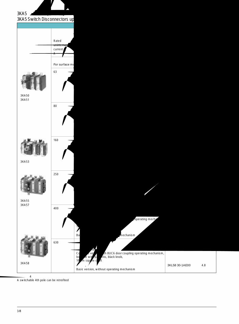
3/8
Selection and ordering data选型及订货数据
3KA5隔离开关(至 630A),三级3KA5 Switch Disconnectors up to 630A, 3-pole
额定不间断电流Rateduninterruptedcurrent Iu
A
订货号 大约重量Order No. Weight
approx
kg
63 完整型,带有 8UC6 门操作机构 3KA50 30-1EE00 1.05可用挂锁锁定黑色旋钮,6mm 方轴Complete version with 8UC6 door coupling operating mechanism,lockable with padlocks, black knob,6mm square shaft
基本型,无操作机构 3KL50 30-1AE00 0.73Basic version, without operating mechanism
用于表面安装和开关柜内安装For surface mounting and for installation in switchboards
类型 Version
防护等级 IP 00 Degree of protection IP 00无辅助触头 without auxiliary contacts带有螺丝端子 with terminal screws接触横杆前面加盖 contact crass-bars covered at front
80 完整型,带有 8UC6 门操作机构 3KA51 30-1EE00 1.05可用挂锁锁定黑色旋钮,6mm 方轴Complete version with 8UC6 door coupling operating mechanism,lockable with padlocks, black knob,6mm square shaft
基本型,无操作机构 3KL51 30-1AE00 0.73Basic version, without operating mechanism
160 完整型,带有 8UC6 门操作机构 3KA53 30-1EE00 2.56可用挂锁锁定黑色旋钮,8mm 方轴Complete version with 8UC6 door coupling operating mechanism,lockable with padlocks, black knob,8mm square shaft
基本型,无操作机构 3KA53 30-1AE00 2.2Basic version, without operating mechanism
250 完整型,带有 8UC6 门操作机构 3KA55 30-1EE00 5.4可用挂锁锁定黑色旋钮,10mm 方轴Complete version with 8UC6 door coupling operating mechanism,lockable with padlocks, black knob,10mm square shaft
基本型,无操作机构 3KL55 30-1AE00 4.6Basic version, without operating mechanism
400 完整型,带有 8UC6 门操作机构 3KA57 30-1EE00 5.4可用挂锁锁定黑色旋钮,10mm 方轴Complete version with 8UC6 door coupling operating mechanism,lockable with padlocks, black knob,10mm square shaft
基本型,无操作机构 3KL57 30-1AE00 4.6Basic version, without operating mechanism
630 完整型,带有 8UC6 门操作机构 3KA58 30-1EE00 5.6可用挂锁锁定黑色旋钮,10mm 方轴Complete version with 8UC6 door coupling operating mechanism,lockable with padlocks, black knob,10mm square shaft
基本型,无操作机构 3KL58 30-1AE00 4.8Basic version, without operating mechanism
3KA503KA51
3KA53
3KA553KA57
3KA58
可加装第 4 极用于通断控制A switchable 4th pole can be retrofited
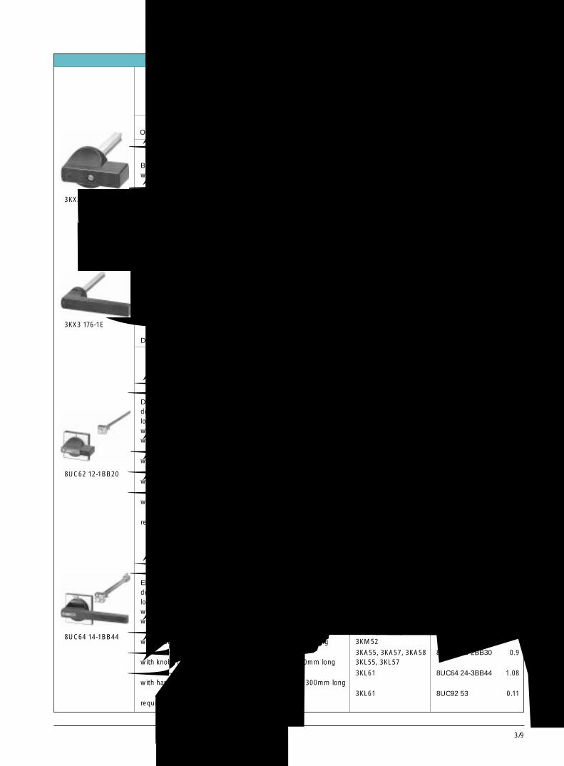
3/9
3
Accessories附件
3KL5与 3KL6带熔断器的隔离开关,3KA5隔离开关3KL5 and 3KL6 Switch Disconnectors with Fuses, 3KA5 Switch Disconnectors
订货号 大约重量Order No. Weight
approxkg
适用的隔离开关For disconnector
黑色旋钮,36mm长 3KA50, 3KA51 3KX3 516-1AA 0.1带有 6mm 方轴,250mm 长 3KL50,Black knob, 36mm longwith 6mm square shaft, 250mm long
黑色旋钮,62mm长 3KA53, 3KL52, 3KL53 3KX3 536-1AA 0.25带有 8mm 方轴,250mm 长Black knob, 62mm longwith 8mm square shaft, 250mm long
黑色手柄,140mm长 3KA55, 3KA57, 3KA58 3KX3 176-1E 0.3带有 10mm 方轴,205mm 长 3KL55, 3KL57Black handle, 140mm longwith 10mm square shaft, 205mm long
黑色双翼手柄,280mm长 3KL61 3KX3 616-1A 0.36带有 12mm 方轴,110mm 长带有耦合片Black double-wing handle, 280mm longwith 12mm square shaft, 110mm longwith coupling piece
可拆卸的操作机构Detchable operating mechanisms
门操作机构防护等级 IP 65可用挂锁锁定具有门联锁,黑色手柄带有旋钮,36mm 长,带有 6mm 方轴,300mm 长 3KA50, 3KA51 8UC61 11-1BB10 0.29Door-coupling operating mechanism 3KL50, 3KM50degree of protection IP 65,lockable with padlocks,with door interlocking, black handlewith knob, 36mm long, with 6mm square shaft, 300mm long
带有旋钮,62mm 长,8mm 方轴,300mm 长 3KA53, 3KL52, 3KL53 8UC62 12-1BB20 0.36with knob, 62mm long, with 8mm squar shaft, 300mm long
带有旋钮,140mm 长,10mm 方轴,300mm 长 3KA55, 3KA57, 3KA58 8UC63 13-1BB30 0.9with knob, 140mm long, with 10mm squar shaft, 300mm long
带有手柄,200mm 长,12mm 方轴,300mm 长 3KL61 8UC64 14-1BB44 1.08with handle, 200mm long, with 12mm square shaft, 300mm long
所需适配器 3KL61 8UC92 53 0.11required adapter
“急停”门联锁操作机构防护等级 IP 65可用挂锁锁定具有门联锁,红色手柄、黄色标志牌带有旋钮,36mm 长,带有 6mm 方轴,300mm 长 3KA50, 3KA51 8UC61 21-3BB10 0.29EMERGENCY STOP door-coupling operating mechanism 3KL50degree of protection IP 65.lockable with padlocks,with door interlocking, red handle,yellow indicator plate,with knob, 36mm long, with 6mm square shaft, 300mm long
带有旋钮,62mm 长,8mm 方轴,300mm 长 3KA53, 3KL52, 3KL53 8UC62 22-3BB20 0.36with knob, 62mm long, with 8mm squar shaft, 300mm long 3KM52
带有手柄,140mm 长,10mm 方轴,300mm 长 3KA55, 3KA57, 3KA58 8UC63 23-2BB30 0.9with knob, 140mm long, with 10mm squar shaft, 300mm long 3KL55, 3KL57
带有手柄,200mm 长,12mm 方轴,300mm 长 3KL61 8UC64 24-3BB44 1.08with handle, 200mm long, with 12mm square shaft, 300mm long
所需适配器 3KL61 8UC92 53 0.11required adapter
固定安装的操作机构Operating mechanisms for fixed mouting
3KX3 516-1AA
3KX3 176-1E
8UC62 12-1BB20
8UC64 14-1BB44
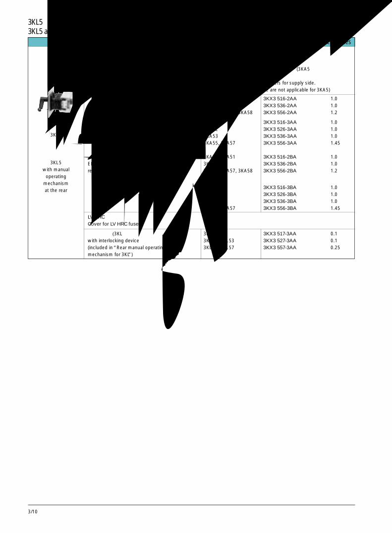
3/10
Accessories附件
3KL5与 3KL6熔断器式隔离开关,3KA5隔离开关3KL5 and 3KL6 Switch Disconnectors with fuses, 3KA5 switch Disconnectors
后部手动操作机构Rear manual operating mechanisms
整套装置带有:防护框架,可锁定手柄,进线侧 3 个端子盖板,LV HRC 熔断器盖板和联锁装置 (3KA5 不能装盖板和联锁装置)。complete assembly with masking frame and lockable handle, including 3 terminal covers for supply side.with cover for LV HRC fuses and interlocking device (covers and interlocking device are not applicable for 3KA5)
黑色手柄 3KA50, 3KA51 3KX3 516-2AA 1.0Black handle 3KA53 3KX3 536-2AA 1.0
3KA55, 3KA57, 3KA58 3KX3 556-2AA 1.2
3KA50 3KX3 516-3AA 1.03KA52 3KX3 526-3AA 1.03KA53 3KX3 536-3AA 1.03KA55, 3KA57 3KX3 556-3AA 1.45
紧急停止型,红色手柄,黄色标志牌 3KA50, 3KA51 3KX3 516-2BA 1.0EMERGENCY STOP version, 3KA53 3KX3 536-2BA 1.0red handle, yellow indicator plate 3KA55, 3KA57, 3KA58 3KX3 556-2BA 1.2
3KA50 3KX3 516-3BA 1.03KA52 3KX3 526-3BA 1.03KA53 3KX3 536-3BA 1.03KA55, 3KA57 3KX3 556-3BA 1.45
LV HRC熔断器盖板Cover for LV HRC fuses
带联锁装置(3KL 后部手动操作机构中已包含) 3KL50 3KX3 517-3AA 0.1with interlocking device 3KL52, 3KL53 3KX3 527-3AA 0.1(included in “Rear manual operating 3KL55, 3KL57 3KX3 557-3AA 0.25mechanism for 3KL”)
3KL5带后部手动操作机构
3KL5with manual
operatingmechanismat the rear
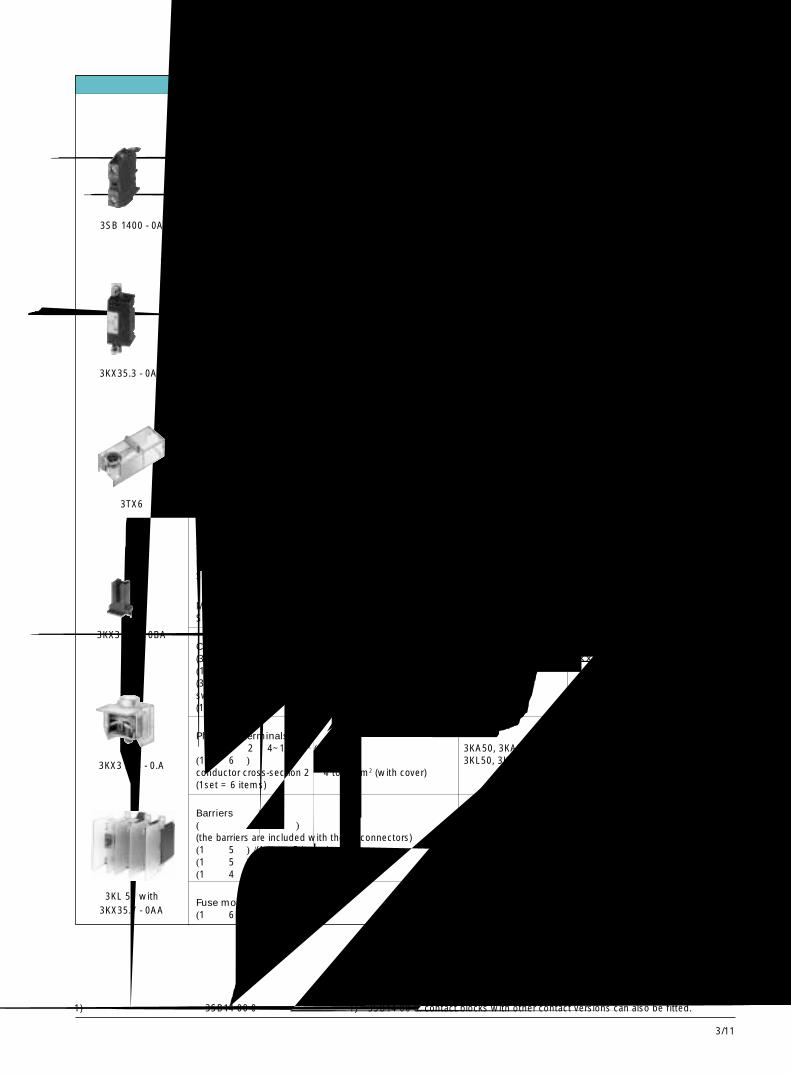
3/11
3
Accessories附件
3KL5与 3KL6熔断器式隔离开关,3KA5隔离开关3KL5 and 3KL6 Switch Disconnectors with fuses, 3KA5 Switch Disconnectors
用于隔离开关 订货号 大约重量For disconnector Order No. Weight
approx.kg
辅助触头座Auxiliary contact blocks1 NO+1NC 3KA5, 3KL5 3SB14 00-0A1) 0.02(可加装辅助触头座的最大数目见技术数据第 12/17 页)(max. number of auxiliary contact blocks to be fittedsee Technical data, pages 12/17 )
1 NO+1NC 3KL61 3KX3 612-1A 0.05包括所需安装零件(此外,还可加装 2 个 3SB14 00-0A1)including required mounting parts(in addition, 2 more 3SB14 00-0A1) contact blockscan be fitted)
第 4极,可通断 3KL53, 3KL52, 3KL53 3KX3 523-0AA4th pole, switchable 3KA55, 3KA57, 3KA58 3KX3 553-0AA 0.5装在右手侧,带安装零件 3KL55, 3KL57to be mounted on the right-hand side, with mounting parts
端子安装配件 3KA50, 3KA51, 3KX3 513-0DA 0.1Kit for terminal fitting 3KL50适用于 35 级以下的 8WA1 端子座;所需端子需单独订货suitable for 8WA1 terminal blocks up to size 35;required terminal to be ordered separately
端子罩(1 套= 6 件)Terminal covers(1set = 6 items)拧至螺钉头上用于振动防护screwable onto free screw end for shock-hazard protectionM6 螺钉罩 3KA50, 3KA51, 3TX6 506-3B 0.1Single cover for M 6 terminal screws 3KL50, 3KL52,
以及 3KX3 523-0AA
M8 螺钉罩 3KA53, 3KL53 3TX6 526-3B 0.1Single cover for M 8 terminal screws
M10 螺钉罩 3KA55, 3KA57, 3KA58, 3TX6 546-3B 0.1Single cover for M 10 terminal screws 3KL55, 3KL57,
以及 3KX3 553-0AA
M12 螺钉罩 3KL61 3TX6 346-3B 0.1Single cover for M 12 terminal screws
触头罩Covers for lyre-shaped contacts(3KM50, 3KM52 与 3KM53 隔离开关有 3 个触头罩) 3KL50, 3KL52, 3KL53 3KX3 507-0BA 0.03(1 套= 6 件)(3 lyre covers supplied with 3KM50, 3KM52 and 3KM53swtch disconnectors)(1set = 6 items)
插入式端子Plug-type terminals导体截面积 2 × 4~16mm2 (带盖板) 3KA50, 3KA51 3KX3 525-0CA 0.1(1 套= 6 件) 3KL50, 3KL52conductor cross-section 2 × 4 to16mm2 (with cover)(1set = 6 items)
隔板Barriers(包含在隔离开关一起)(the barriers are included with the disconnectors)(1 套= 5 件)/(1 set = 5 items) 3KL50, 3KL52 3KL53 3KX3 507-0AA 0.1(1 套= 5 件)/(1 set = 5 items) 3KL55, 3KL57 3KX3 557-0AA 0.2(1 套= 4 件)/(1 set = 4 items) 3KL61 3KY3 612-0A 0.17
熔断器监测端子Fuse monitoring connection(1 套= 6 件)/(1set = 6 items) 3KL5 3KX3 505-0AA 0.25
1) 也可加装其它触头类型的 3SB14 00-0 辅助触头座。
3SB 1400 - 0A
3KX35.3 - 0AA
3TX6
3KX3 507 - 0BA
3KX3 525 - 0.A
3KL 50 with3KX35.7 - 0AA
1) 3SB14 00-0. contact blocks with other contact versions can also be fitted.
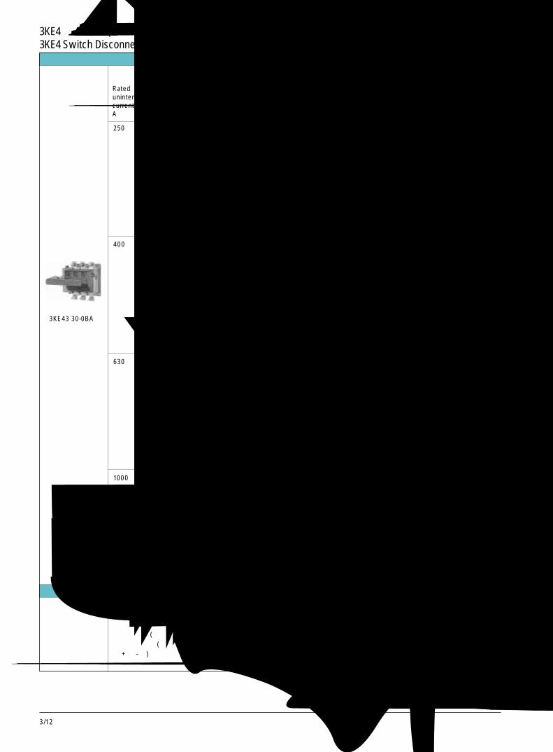
3/12
Selection and ordering data选型及订货数据额定不间断电流Rateduninterruptedcurrent Iu
A
订货号 大约重量Order No. Weight
approx
kg
250 完整型,带有8UC6门操作机构 3KE42 30-0EA 4.58可用挂锁锁定黑色手柄,12mm 方轴Complete version with 8UC6 door coupling operating mechanism,lockable with padlocks, black handle,12mm square shaft
前面操作机构,无手柄 3KE42 30-0AA 3.5Front operating mechanism, without handle
前面操作机构,具有黑色手柄 3KE42 30-0BA 3.6Front operating mechanism, with black handle
后面操作机构,无手柄 3KE42 30-0CA 4.4Rear operating mechanism, without handle
类型 Version
防护等级 IP 00 Degree of protection IP 00具有快速闭合与分断特性 with high-speed closing and opening feature无辅助触头 without auxiliary contacts带有螺丝端子 with terminal screws
400 完整型,带有8UC6门操作机构 3KE43 30-0EA 4.58可用挂锁锁定黑色手柄,12mm 方轴Complete version with 8UC6 door coupling operating mechanism,lockable with padlocks, black handle,12mm square shaft
前面操作机构,无手柄 3KE43 30-0AA 3.5Front operating mechanism, without handle
前面操作机构,具有黑色手柄 3KE43 30-0BA 3.6Front operating mechanism, with black handle
后面操作机构,无手柄 3KE43 30-0CA 4.4Rear operating mechanism, without handle
630 完整型,带有8UC6门操作机构 3KE44 30-0EA 6.68可用挂锁锁定黑色手柄,12mm 方轴Complete version with 8UC6 door coupling operating mechanism,lockable with padlocks, black handle,12mm square shaft
前面操作机构,无手柄 3KE44 30-0AA 5.6Front operating mechanism, without handle
前面操作机构,具有黑色手柄 3KE44 30-0BA 5.7Front operating mechanism, with black handle
后面操作机构,无手柄 3KE44 30-0CA 6.5Rear operating mechanism, without handle
1000 完整型,带有8UC6门操作机构 3KE45 30-0EA 7.18可用挂锁锁定黑色手柄,12mm 方轴Complete version with 8UC6 door coupling operating mechanism,lockable with padlocks, black handle,12mm square shaft
前面操作机构,无手柄 3KE45 30-0AA 6.1Front operating mechanism, without handle
前面操作机构,具有黑色手柄 3KE45 30-0BA 6.3Front operating mechanism, with black handle
后面操作机构,无手柄 3KE45 30-0CA 7Rear operating mechanism, without handle
3KE43 30-0BA
Accessories附件下列附件可供选择:固定安装式的操作机构可拆卸式操作机构轴连接机构 (用于 2 台隔离开关的并行通断)切换操作机构 (电动机式): 有间断(Ⅰ- 0 -Ⅱ)或无间断(Ⅰ-Ⅰ + Ⅱ -Ⅱ)辅助触头端子罩
3KE4 隔离开关(至 1000A)3KE4 Switch Disconnectors up to 1000A
Further accessories are available on request:Operating mechanisms for fixed mountingDetachable operating mechanismShifting linkage (parallel switching of 2 switch disconnectors)Change over operating mechanism (motorized): with interruption(Ⅰ - 0 - Ⅱ) or without interruption (Ⅰ - Ⅰ + Ⅱ - Ⅱ)Auxiliary switch terminal cover
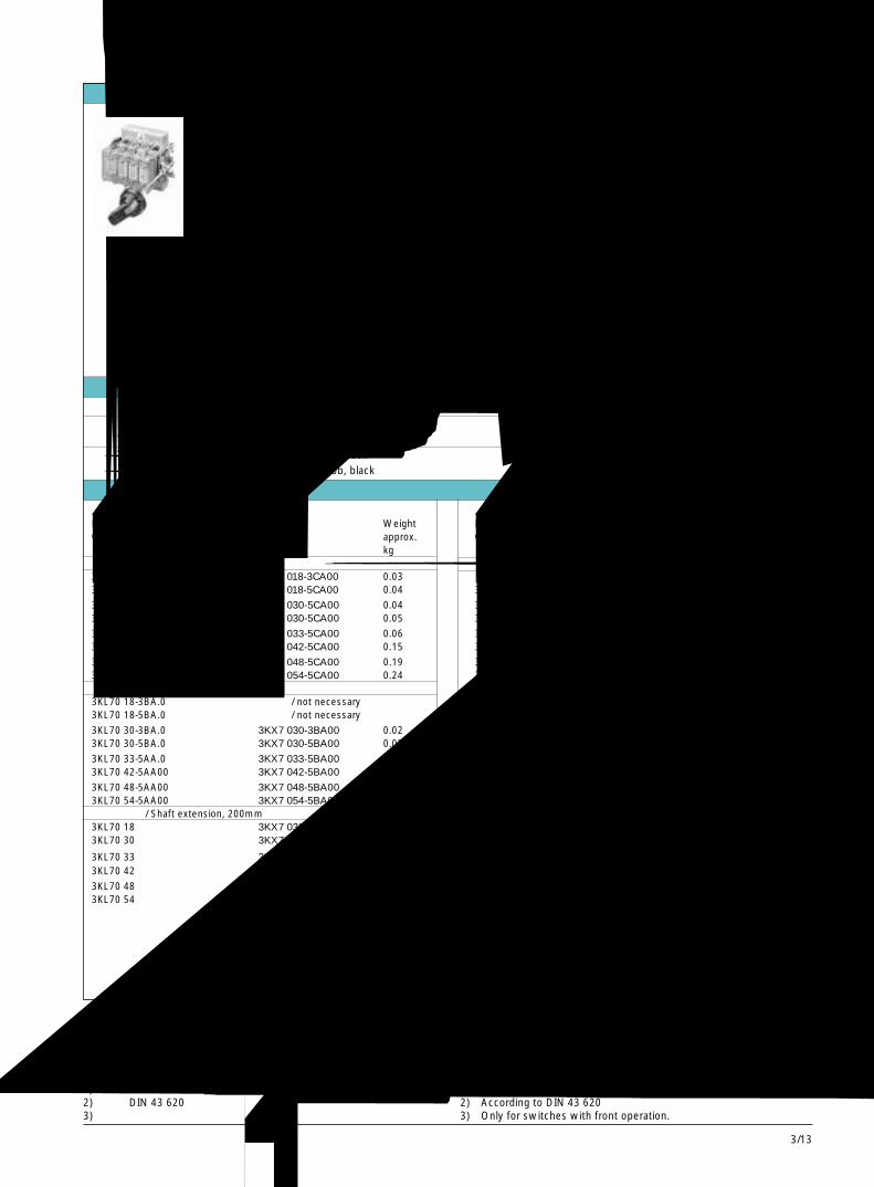
3/13
3
Selection and ordering data
3KL7带熔断器的隔离开关,3 极和 4极最大 100A,4极最大 630A3KL7 Switch Disconnectors with Fuses, 3 and 4-pole Up to 100A, 4-pole up to 630A
额定电流 规格 极数 所用熔丝 订货号 重量Rated current Size Number of poles For fuse links Order No. WeightIn approx.
如需附加订货号见下表Order No.supplement
规格 (if necessary),A Size see table below kg50 1 3 14 x 511) 3KL70 18-3BA.0 1.2
4 14 x 511) 3KL70 18-5BA.0 1.5100 2 3 22 x 581) 3KL70 30-3BA.0 1.8
4 22 x 581) 3KL70 30-5BA.0 2.2125 2 4 LV HRC 002) 3KL70 33-5AA 0 2.2250 4a 4 LV HRC 12) 3KL70 42-5AA 0 8.4400 4b 4 LV HRC 22) 3KL70 48-5AA 0 8.8463 5 4 LV HRC 32) 3KL70 54-5AA 0 19.3
附加订货号 Order No. supplement柜门联锁式旋转操作机构 / Door-coupling rotary operating mechanism
附加订货号 /Order No. supplement3KL70 ..-..A�0
前面带操作手柄,黑色 / Front operation with knob, black 0侧面带操作手柄,黑色 / Lateral operation with knob, black 1
附件 Accessories适用的熔丝开关 订货号 重量 适用的熔丝开关 订货号 重量For switch disconnector Order No. Weight For switch disconnector Order No. Weightwith fuses approx. with fuses approx.
kg kg熔丝盖板 / Cover for fuses 辅助触点 / Auxiliary switch3KL70 18-3BA.0 3KX7 018-3CA00 0.03 型式 / Version3KL70 18-5BA.0 3KX7 018-5CA00 0.04 3KL70 18 1 NO+1NC 3KX7 033-0AA00 0.13
3KL70 30-3BA.0 3KX7 030-5CA00 0.04 3KL70 30 3KX7 033-0AA00 0.133KL70 30-5BA.0 3KX7 030-5CA00 0.05 3KL70 33 3KX7 033-0AA00 0.13
3KL70 33-5AA.0 3KX7 033-5CA00 0.06 3KL70 42 3KX7 048-0AA00 0.133KL70 42-5AA00 3KX7 042-5CA00 0.15 3KL70 48 3KX7 048-0AA00 0.13
3KL70 48-5AA00 3KX7 048-5CA00 0.19 3KL70 54 3KX7 054-0AA00 0.143KL70 54-5AA00 3KX7 054-5CA00 0.24 3KL70 18 2 NO+2NC 3KX7 033-0AB00 0.21端子盖板 / Terminal cover 3KL70 30 3KX7 033-0AB00 0.213KL70 18-3BA.0 不需要 / not necessary 3KL70 33 3KX7 033-0AB00 0.213KL70 18-5BA.0 不需要 / not necessary 3KL70 42 3KX7 048-0AB00 0.21
3KL70 30-3BA.0 3KX7 030-3BA00 0.02 3KL70 48 3KX7 048-0AB00 0.213KL70 30-5BA.0 3KX7 030-5BA00 0.02 3KL70 52 3KX7 054-0AB00 0.22
3KL70 33-5AA.0 3KX7 033-5BA00 0.02 锁闭装置 / Locking device3)3KL70 42-5AA00 3KX7 042-5BA00 0.09 3KL70 18 3KX7 033-0HA00 0.11
3KL70 48-5AA00 3KX7 048-5BA00 0.12 3KL70 30 3KX7 033-0HA00 0.113KL70 54-5AA00 3KX7 054-5BA00 0.17 3KL70 33 3KX7 033-0HA00 0.11转轴延长杆 / Shaft extension, 200mm 3KL70 48 3KX7 048-0HA00 0.163KL70 18 3KX7 033-0EA00 0.08 3KL70 48 3KX7 048-0HA00 0.163KL70 30 3KX7 033-0EA00 0.08 3KL70 52 3KX7 054-0HA00 0.16
3KL70 33 3KX7 033-0EA00 0.08 柜门联锁式旋转操作机构,红-黄/Door-coupling rotary operating mechanism, red-yellow3KL70 42 3KX7 048-9EA00 0.24 3KL70 18 3KX7 033-0FB00 0.15
3KL70 48 3KX7 048-0EA00 0.24 3KL70 30 3KX7 033-0FB00 0.153KL70 54 3KX7 054-0EA00 0.36 3KL70 33 3KX7 033-0FB00 0.15
3KL70 48 3KX7 048-0FB00 0.173KL70 48 3KX7 048-0FB00 0.173KL70 52 3KX7 054-0FB00 0.28直接操作机构,黑色 / Direct operating mechanism, black3KL70 18 3KX7 516-1AA 0.103KL70 30 3KX7 516-1AA 0.103KL70 33 3KX7 516-1AA 0.10
选型与订货数据
1) 圆柱形熔丝按 IEC 269-2-1 和 DIN VDE 0636 第 107 部分2) 按照 DIN 43 6203) 仅用于前面操作
1) Cylindrical fuses acc.to IEC 2690201 and DIN VDE 0636 Pary 1072) According to DIN 43 6203) Only for switches with front operation.

3/14
IEC 947-1, IEC947-3, DIN VDE 0660 Part 107
3KL50 3KL52
63 12500 00
63 125
690 1000
690440 (3 个电流通路串联/220 (2 个电流通路串联/
210 210
100 10080 160
8 17
- -
- -
500 100063 12530 65
500 100063 12563 12540 90
500 100063 12563 12550 110
250 50063 1252.5 3.2
运行 4): -25到+55, 储存 -50到+80。/
15000 15000
3 7.5
IP 00/IP 20 (从面板处,带母排和端子罩/
8.5 22
15 × 2 15 × 335 70
6-7.5 7-10M6 M6
- -- -
- 125- 125- 15 × 3- 70
1 2
10220/230 380/4006 424 4810 42 ×(1-2.5)2 ×(0.5-1.5)
3KL5熔断器式隔离开关,至 400A,3KL6至 630A3KL5 Switch Disconnectors with Fuses up to 400A , 3KL6 up to 630A技术数据标准/Standards
型号/Type
额定不间断电流 In/Rated uninterrupted current In A对于熔断器 DIN 43 620/for fuse links according to DIN 43 620 Size(使用半导体熔断器需要降容,见 DA 94.1 样本)(The use of semiconductor protection fuses requires a current reduction; see Catalog DA 94.1)
约定封闭发热电流 Ith/Conventional free-air thermal current Ith A
额定绝缘电压Ui/Rated insulation voltage Ui AC V
额定工作电压Ue /Rated operational voltage Ue AC 50/60 Hz VDC V
额定短路接通能力,带熔断器 2)/Rated short-circuit making capacity with fuses2)at AC 50/60Hz 690V kA(峰值/peak value)
额定条件性短路电流,带熔断器 2)/Rated conditional short-circuit current with fuses2)at AC 50/60Hz 690V kA(峰值/peak value)熔断器最大额定电流In/max. current ratings In of the fuses A
允许熔断器切断电流 3)/Permissible cut-off current of the fuses3) kA
断路器串联后的允许切断电流/Permissible cut-off current of a circuit-breaker connected in seriesat AC 50/60Hz 690V KA(峰值/peak value)
额定短路接通能力,无熔断器/Rated short-circuit making capacity without fusesat AC 50/60Hz 690V KA(峰值/peak value)
通断能力(从顶端或底部进线)/Switching capacity (teed-in from the top or bottom)
at AC 400V分断电流/Breaking current Ic (p.f.=0.35) A(峰值/rms value)额定工作电流/Rated operational current Ie at AC-21, AC-22, AC-23 A电机通断能力/Motor switching capacityAC-23 kW
at AC 500V分断电流/Breaking current Ic (p.f.=0.35) A(峰值/rms value)额定工作电流/Rated operational current Ie at AC-21, AC-22, AC-23 A
A电机通断能力/Motor switching capacity AC-23 kW
at AC 690V分断电流/Breaking current Ic (p.f.=0.35) A(峰值/rms value)额定工作电流/Rated operational current Ie at AC-21, AC-22, AC-23 A
A电机通断能力/Motor switching capacity AC-23 kW
at DC 440V (3 个电流通断串连/3 conducting paths series connected)分断电流/Breaking current Ic (L/R=15 ms) A额定工作电流/Rated operational current Ie at DC-23 A
额定短时电流(1 s 电流)/Rated short-time current (1 s current) kA(峰值/rms ralue)
允许环境温度/Permissible ambient temperature ºC
机械寿命/Mechanical Endurance 操作循环/Operating cycles
所需操作力矩/Required operating torque Nm
防护等级/Degree of protection
Ith时隔离开关功率损耗/Power loss of the switch disconnector at Ith W(加上熔断器的功率损耗)/(Plus power loss of the fuse links)
主回路导体/Main conductor connection扁平排/Flat bars mm × mm接线片,最大导体截面积(绞合线)/Cable lug,max.conductor cross-section(stranded) mm2
拧紧力矩/Tightening torque Nm固定螺钉/Fixing screws
保护回路导体/Protective conductor connection扁平排/Flat bars mm × mm接线片,最大导体截面积(绞合线)/Cable lug,max.conductor cross-section(stranded) mm2
可加装的第四极(附件)/Attachable 4th pole (accessory)额定持续电流Iu/Rated continuous current Iu A额定工作电流/Rated operational current Ie at AC-21,AC690V A主回路导体 扁平排/Flat bars mm × mmMain conductor 接线片/Cable lug mm2
connection 最大导体截面积(绞合线)/Max.conductor cross-section (stranded)
辅助触头座 1NO+1 NC (附件)/Auxiliary contact blocks 1NO+1 NC (accessories)可加装的最大数目/Max.number to be plugged
额定工作电流Ie/Rated operational current Ie Aat AC 50/60 Hz Ie/AC-12 V
Ie/AC-15 at Ue Aat DC Ie/AC-13 at Ue V
A实芯线/Connection solid mm2
细绞线带断子套管/finely stranded win end sleeve mm2
1) 有关 CSA 技术数据请查询。Technical data for CSA approval on request.
2) 只适用 3NA38, 3NA32或3ND18, 3ND12熔断器(105kA,其它熔断器是50kA)Only for 3NA38, 3NA32 or 3ND18 3ND12 fuses (105 kA,50kA for others).
3) 3ND1开关保护熔断器。3ND1 switchgear protection fuses.
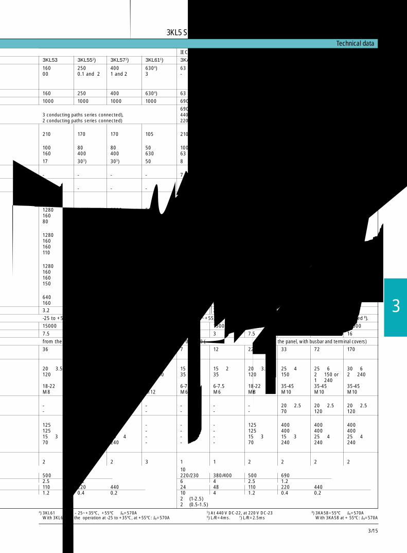
3/15
3
4) 3KL61运行时为-25~+35ºC, +55ºC时Ith=570AWith 3KL61 for the operation at -25 to +35ºC, at +55ºC: Ith=570A
5) At 440 V DC-22, at 220 V DC-236) L/R=4ms. 7) L/R=2.5ms
8) 3KA58+55ºC时Ith=570AWith 3KA58 at + 55ºC: Ith=570A
IEC 947-1, IEC947-3, DIN VDE 0660 Part 107
3KL53 3KL551) 3KL571) 3KL611) 3KA50 3KA51 3KA531) 3KA55 3KA571) 3KA58
160 250 400 6304) 63 80 160 250 400 6308)00 0.1 and 2 1 and 2 3 - - - - - -
160 250 400 6304) 63 80 160 250 400 6308)
1000 1000 1000 1000 690 690 1000 1000 1000 1000
6903 conducting paths series connected), 440 (3 个电流通路串联/3 conducting paths series connected),2 conducting paths series connected) 220 (2 个电流通路串联/2 conducting paths series connected)
210 170 170 105 210 210 210 170 170 105
100 80 80 50 100 100 100 80 80 50160 400 400 630 63 80 160 250 400 630
17 303) 303) 50 8 10 17 303) 303) 403)
- - - - 7 8 15 25 25 32
- - - - 7 7 9 20 25 35
1280 2000 3200 5100 500 650 1280 2000 3200 5040160 250 400 630 63 80 160 250 400 63080 132 200 335 30 40 80 132 200 350
1280 2000 3200 5100 500 640 1280 2000 3200 3200160 250 400 630 63 80 160 250 400 630160 250 400 630 63 80 160 250 400 400110 185 280 425 40 50 110 185 280 280
1280 2000 3200 5100 500 500 1280 2000 3200 3200160 250 400 630 63 80 160 250 400 630160 250 400 630 63 63 160 160 400 400150 220 375 560 50 50 150 132 375 375
640 10006) 1600 25207) 260 260 640 10006) 1600 1600160 2503) 400 6305) 63 63 160 2505) 400 4003.2 8 11 32 2.5 2.5 3.2 8 11 15
-25 to +55 in operation 4), -50 to +80 when stored. 运行:-25~+55, 储存 -50到+80 8)。/-25 to +55 in operation, -50 to +80 when stored 8).
15000 12000 12000 3000 15000 15000 15000 12000 12000 12000
7.5 16 16 30 3 3 7.5 16 16 16
from the panel, with busbar and terminal covers) IP 00/IP 20 (从面板处,带母排和端子罩/from the panel, with busbar and terminal covers)
36 33 86 140 7 12 22 33 72 170
20 × 3.5 25 × 4 25 × 6 40 × 6 15 × 2 15 × 2 20 × 3.5 25 × 4 25 × 6 30 × 6120 150 2 × 150 or 2 × 240 35 35 120 150 2 × 150 or 2 × 240
1 × 240 1 × 24018-22 35-45 35-45 56 6-7.5 6-7.5 18-22 35-45 35-45 35-45M8 M10 M10 M12 M6 M6 M8 M10 M10 M10
- 20 × 2.5 20 × 2.5 - - - - 20 × 2.5 20 × 2.5 20 × 2.5- 70 120 - - - - 70 120 120
125 400 400 - - - 125 400 400 400125 400 400 - - - 125 400 400 40015 × 3 25 × 4 25 × 4 - - - 15 × 3 15 × 3 25 × 4 25 × 470 240 240 - - - 70 240 240 240
2 2 2 3 1 1 2 2 2 2
10500 690 220/230 380/400 500 6902.5 1.2 6 4 2.5 1.2110 220 440 24 48 110 220 4401.2 0.4 0.2 10 4 1.2 0.4 0.2
2 ×(1-2.5)2 ×(0.5-1.5)
Technical data
3KL5熔断器式隔离开关,至 400A,3KL6至 630A3KL5 Switch Disconnectors with Fuses up to 400A , 3KL6 up to 630A

3/16
技术参数 Technical data标准 /Standards IEC 947-1, IEC 947-3, DIN VDE 0660 Part 107型号 /Type 3KL70 18 3KL70 30 3KL70 33 3KL70 42 3KL70 48 3KL70 54额定电流 In A 50 100 125 250 400 630Rated uninterrupted current In
额定绝缘电压Ui V 690Rated insulation voltage Ui
AC-22B时的额定热电流和额定运行电流 封闭的 at AC 50/60Hz 690V A 50 100 125 250 400 630环境温度 40°C 自由空气 690V A 50 100 115 250 345 540Rated thermal current and rated tree airoperational current at AC-22B, enclosed40°C ambient temperature额定运行电压 Ue AC V 690Rated operational voltage Ue
AC23B, AC-3时的额定电流 at AC 50/60Hz 220V A 50 100 125 250 400 630AC-3时动作周期间隔 30s 380V A 50 100 125 250 400 630Rated operational current at AC-22B and 415V A 50 100 125 250 400 630AC-3, 30 s time interval between 550V A 50 100 125 250 400 630the operating cycles at AC-31) 690V A 50 100 125 250 400 630
DC-23B时额定电流 1 导电通路 DC 110V A 50 100 125 250 400 630Rated opertational current at DC-23B 2 导电通路,串联 250V A 50 100 125 250 400 630
2 导电通路,串联 500V A 50 100 80 250 400 -1 conducting path at DC2 conducting path in series2 conducting path in series
AC23B, AC-3时的额定电流 at AC 50/60Hz 220V kW 11 30 37 75 132 200AC-3时动作周期间隔 30s1) 380V kW 22 55 55 132 185 315Rated operational power at AC-23B and AC-3 415V kW 30 55 60 132 225 37530 s time interval betweenthe operating cycles at AC-31) 550V kW 37 75 90 185 300 400
690V kW 45 90 110 225 330 540开断能力 AC at AC 50/60Hz 550V A 400 800 1000 2000 3200 5040p.f. = 0.35 690V A 400 800 1000 2000 3200 5040开断能力 DC 1 导电通路 DC 110V A 200 400 500 800 1600 2520L/R = 15ms 2 导电通路,串联 250V A 200 400 500 800 1600 2520Rated breaking capacity, AC, 2 导电通路,串联 500V A 200 320 320 800 - -p.f. = 0.35 1 conducting path at DCRated breaking capacity, DC, 2 conducting path in seriesL/R = 15ms 2 conducting path in series带熔丝时额定短路电流 有效值 at AC 50/60Hz 690V kA 100 100 100 100 50 50Rated short-circuit current with fuses 峰值 690V kA 210 210 210 210 105 105
rms valuepeak value
额定短路接通能力 有效值 at AC 50/60Hz 690V kA 100 100 100 100 50 50Rated short-circuit making capacity 峰值 690V kA 210 210 210 210 105 105
rms valuepeak value
额定短路耐受能力 有效值 at AC 50/60Hz 690V kA 11 15 15 29 52 71Rated short-time current rms value 690V kA 3.2 5 5 10 10 16withstand capacity电容分断能力 2) at AC 50/60Hz 415V kvar 20 50 90 140 140 250Capacitance switching capacity2)
额定冲击耐受电压 峰值 kV 10 12 12 12 12 12Rated impulse withstand voltage peak value机械寿命 operating cycles 20000 15000 15000 10000 10000 5000Mechanical endurance 循环操作熔丝规格 NFC 14x51 22x58 - - - -Fuse sizes DIN 43 620 - - 00 1 2 3主回路端子 螺丝 M5 M6 M6 M10 M10 M14Main conductor connection 拧紧力矩 Nm 2.0 5.0 5.0 25.0 25.0 50.0
Terminal screwsTightening torque
辅助开关 Ith=10A at Ue=AC-11时额定电流 AC 50/60Hz 48V A 10 10 10 10 10 10Auxiliary switch, Ith = 10A 110V A 10 10 10 10 10 10Rated operational current at AC-11 220/240V A 6 6 6 6 6 6
380/440V A 4 4 4 4 4 4
3KL7带熔断器的隔离开关,3 极和 4极最大 100A,4极最大 630A3KL7 Switch Disconnectors with Fuses, 3 and 4-pole Up to 100A, 4-pole up to 630A

3/17
3
3KA5 switch disconnectors3KA5隔离开关
隔离开关Disconnectors
3KA50, 63A, 3KA51, 80A,无连接轴,无操作机构3KA50, 63A, 3KA51, 80A,without shaft,without operating mechanism
连接轴(立面图)长度:最小:70 毫米最大:150 毫米
Shaft (profile)Engaged length:min. 70mmmax. 150mm
3KA50, 63A3KA51, 80A具有连接轴和8UC6操作机构3KA50, 63A3KA51, 80Awith shaft and8UC6 operatingmechanism
a 连接轴长度Shaft length
最大 380 300; 未变化的 8UC61 连接轴max. 380 300; unchanged shaft from 8UC61最小 175 175-80; 缩短的 8UC61 连接轴min. 175 175-80; shortened shaft from 8UC61≥ 175 ...≤ 380 a-80
3KA53, 160A无连接轴,无操作机构3KA53, 160Awithout shaft,without operating mechanism
连接轴(立面图) 长度:最小:90 毫米最大:143 毫米Shaft (profile) Engaged length:min. 90mm max. 143mm
3KA53, 160A具有连接轴和8UC6操作机构3KA53, 160Awith shaft and8UC6 operatingmechanism
a 连接轴长度Shaft length
最大 350 300; 未变化的 8UC62 连接轴max. 350 300; unchanged shaft from 8UC62最小 165 165-50; 缩短的 8UC62 连接轴min. 165 165-50; shortened shaft from 8UC62≥ 165 ...≤ 350 a-50
3KA55, 250A 3KA57, 400A无连接轴,无操作机构3KA55, 250A 3KA57, 400Awithout shaft, withoutoperating mechanism
连接轴(立面图) 长度:最小:170 毫米最大:205 毫米Shaft (profile) Engaged length:min. 170mm max. 205mm
3KA55, 250A3KA57, 400A3KA58, 630A具有连接轴和8UC6操作机构3KA55, 250A3KA57, 400A3KA58, 630Awith shaft and8UC6 operatingmechanism
第四极 3KX3 553-0AA用于 3KA55, 3KA57,3KA584th pole 3KX3 553-0AAfor 3KA55, 3KA57,3KA58
a 连接轴长度Shaft length
最大 335 300; 未变化的 8UC63 连接轴max. 335 300; unchanged shaft from 8UC63最小 230 230-35; 缩短的 8UC63 连接轴min. 230 230-35; shortened shaft from 8UC63≥ 230 ...≤ 335 a-35
连接轴(立面图) 长度:最小:170 毫米最大:205 毫米Shaft (profile) Engaged length:min. 170mmmax. 205mm3KA58, 630A无连接轴,无操作机构
3KA58, 630A, without shaft, without operating mechanism
3KA553KA57
3KA58
第四极 3KX3 523-0AA用于 3KA534th pole 3KX3 523-0AA for 3KA53
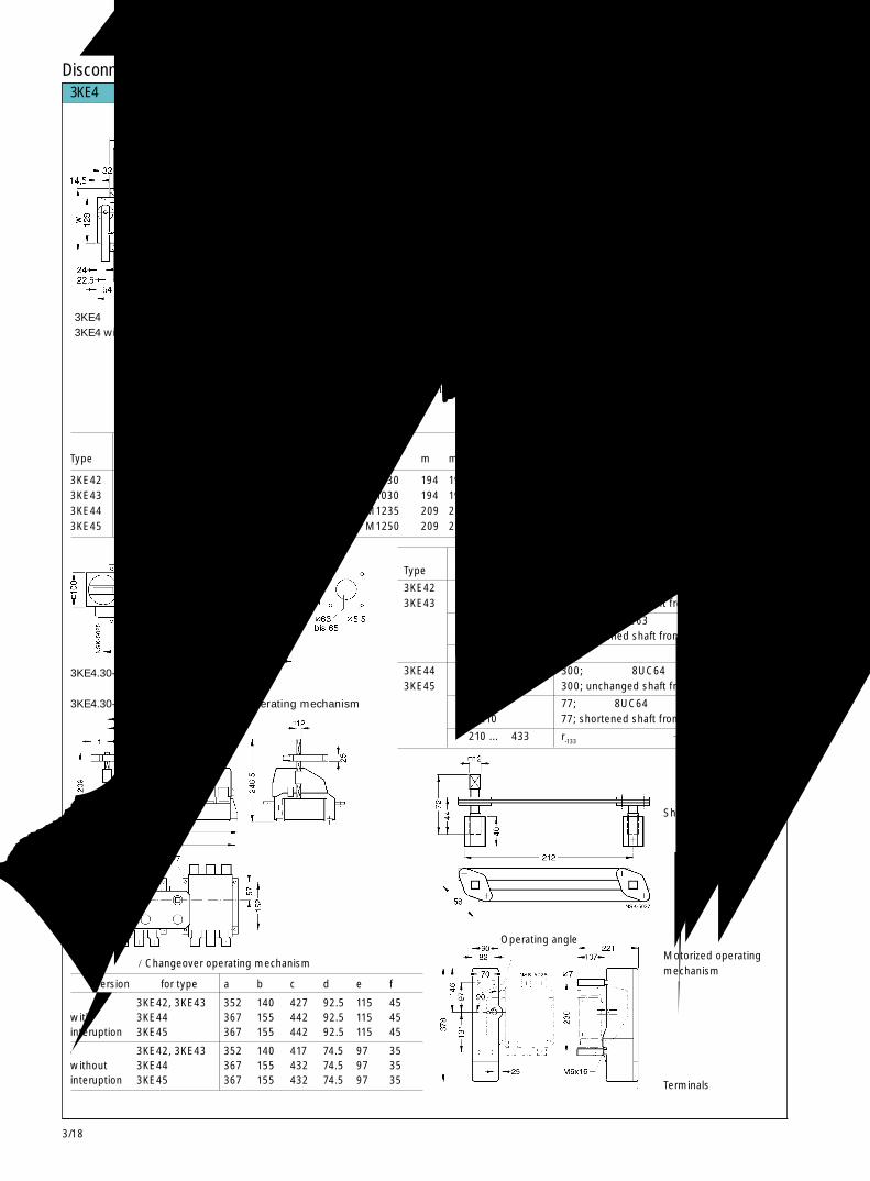
3/18
3KE4 switch disconnectors3KE4隔离开关
隔离开关Disconnectors
型号Type a b c d e f g h k l m m1 n n1 o p s t u v w y z
3KE42 125 155 170 140 25 200 40 60 175 M1030 194 194 129 121 4 150 15 - 105 140 170 50 503KE43 125 155 170 140 25 200 47 60 175 M1030 194 194 129 121 4 150 15 - 105 140 170 50 503KE44 138 170 192 155 40 278 55 65 238 M1235 209 208 144 136 5 161 23 3.5 121 200 172 - -3KE45 138 170 192 155 40 290 65 68 250 M1250 209 208 144 136 8 161 23 3.5 121 200 172 - -
3KE4具有前面操作机构,带手柄3KE4 with front operating mechanism, with handle
这些空间必须保留(用于飞弧)This space must remain free(arc ejection)
这些空间必须保留(用于飞弧)This space must remain free (arc ejection)
3KE4具有后面操作机构,无手柄3KE4 with rear operatingmechanism, without handle
3KE4.30-0EA具有连接轴和 8UC6操作机构3KE4.30-0EA with shfat and 8UC6 operating mechanism
规格 Version 用于 for type a b c d e f
有间断 3KE42, 3KE43 352 140 427 92.5 115 45with 3KE44 367 155 442 92.5 115 45interuption 3KE45 367 155 442 92.5 115 45
无间断 3KE42, 3KE43 352 140 417 74.5 97 35without 3KE44 367 155 432 74.5 97 35interuption 3KE45 367 155 432 74.5 97 35
切换操作机构/Changeover operating mechanism
型号 r 连接轴长度 qType Shaft length
3KE42 最大:433 300; 未变化的 8UC63 连接轴 1403KE43 max. 433 300; unchanged shaft from 8UC63
最小:200 67; 缩短的 8UC63 连接轴 140min. 200 67; shortened shaft from 8UC63
≥ 200 ...≤ 433 r-133 140
3KE44 最大 433 300; 未变化的 8UC64 连接轴 2003KE45 max. 433 300; unchanged shaft from 8UC64
最小 210 77; 缩短的 8UC64 连接轴 200min. 210 77; shortened shaft from 8UC64
≥ 210 ...≤ 433 r-133 200
轴连接机构Shifting linkage
电动机操作机构Motorized operatingmechanism
不能用作操作机构Not to be used as anoperating mechanism
操作角度Operating angle
端子Terminals
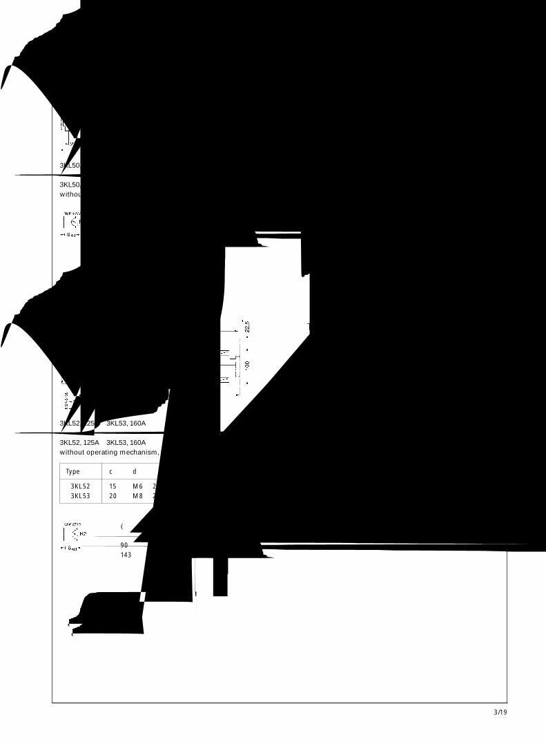
3/19
3
3KL5 switch disconnectors with fuse3KL5熔断器式隔离开关
隔离开关Disconnectors
3KL50, 63A无操作机构,具有层形触头3KL50, 63Awithout operating mechanism, with lyre-shaped contacts
3KL50, 63A具有连接轴和 8UC6操作机构3KA50, 63A with shaft and 8UC6 operating mechanism
a 连接轴长度Shaft length
最大 380 300; 未变化的 8UC61 连接轴max. 380 300; unchanged shaft from 8UC61最小 175 175-80; 缩短的 8UC61 连接轴min. 175 175-80; shortened shaft from 8UC61≥ 175 ...≤ 380 a-80
连接轴(立面图)长度:最小:70 毫米最大:150 毫米
Shaft (profile)Engaged length:min. 70mmmax. 150mm
3KL52, 125A 3KL53, 160A无操作机构,具有层形触头3KL52, 125A 3KL53, 160Awithout operating mechanism, with lyre-shaped contacts
3KL52, 125A 3KL53, 160A具有连接轴和 8UC6操作机构3KA52, 125A 3KL53, 160Awith shaft and 8UC6 operating mechanism
a 连接轴长度Shaft length
最大 350 300; 未变化的 8UC61 连接轴max. 350 300; unchanged shaft from 8UC61最小 165 175-50; 缩短的 8UC61 连接轴min. 165 175-50; shortened shaft from 8UC61≥ 165 ...≤ 350 a-50
连接轴(立面图)长度:最小:90 毫米最大:143 毫米
Shaft (profile)Engaged length:min. 90mmmax. 143mm
Type型号 c d e g h i l
3KL52 15 M6 × 20 37 42 91 3 ø6.63KL53 20 M8 × 25 39 39.5 105 3.5 ø9
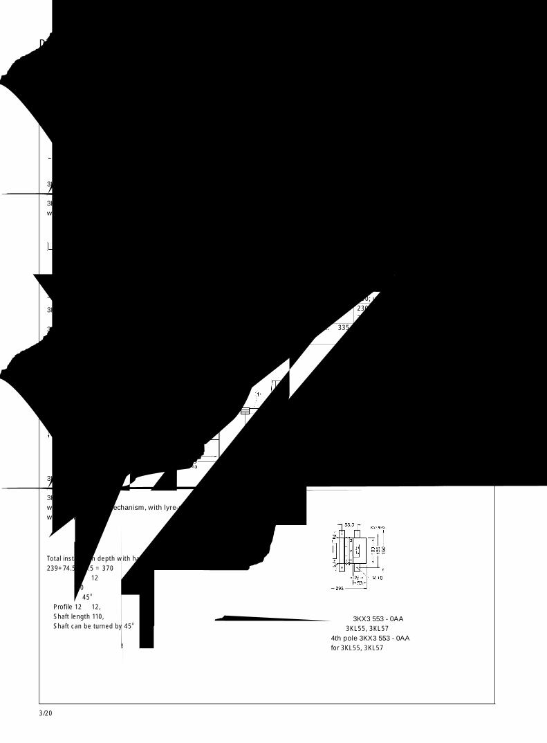
3/20
3KL5 and 3KL6 switch disconnectors with fuses3KL5与 3KL6隔离开关
隔离开关Disconnectors
3KL55, 250A 3KL57, 400A,无操作机构,具有层形触头3KL55, 250A, 3KL57 400A,without operating mechanism, with lyre-shaped contacts
3KL55, 250A 3KL57, 400A具有连接轴和 8UC6操作机构3KL55, 250A 3KL57, 400Awith shaft and 8UC6 operating mechanism
a 连接轴长度Shaft length
最大 335 300; 未变化的 8UC61 连接轴max. 335 300; unchanged shaft from 8UC61最小 230 230-35; 缩短的 8UC61 连接轴min. 230 230-35; shortened shaft from 8UC61≥ 230 ...≤ 335 a-35
连接轴(立面图)长度:最小:170 毫米最大:205 毫米
Shaft (profile)Engaged length:min. 170mmmax. 205mm
Type型号 a b c
3KL55 40 4 M10 × 303KL57 38 6 M10 × 36
3KL61, 630A无操作机构,具有层形触头,带隔离板3KL61, 630Awithout operating mechanism, with lyre-shaped contacts,with barriers
带手柄的总安装深度Total installation depth with handle:239+74.5+66.5 = 370①立面:12 × 12轴长:110轴能转动 45o
Profile 12 × 12,Shaft length 110,Shaft can be turned by 45o
第四极 3KX3 553 - 0AA用于 3KL55, 3KL574th pole 3KX3 553 - 0AAfor 3KL55, 3KL57
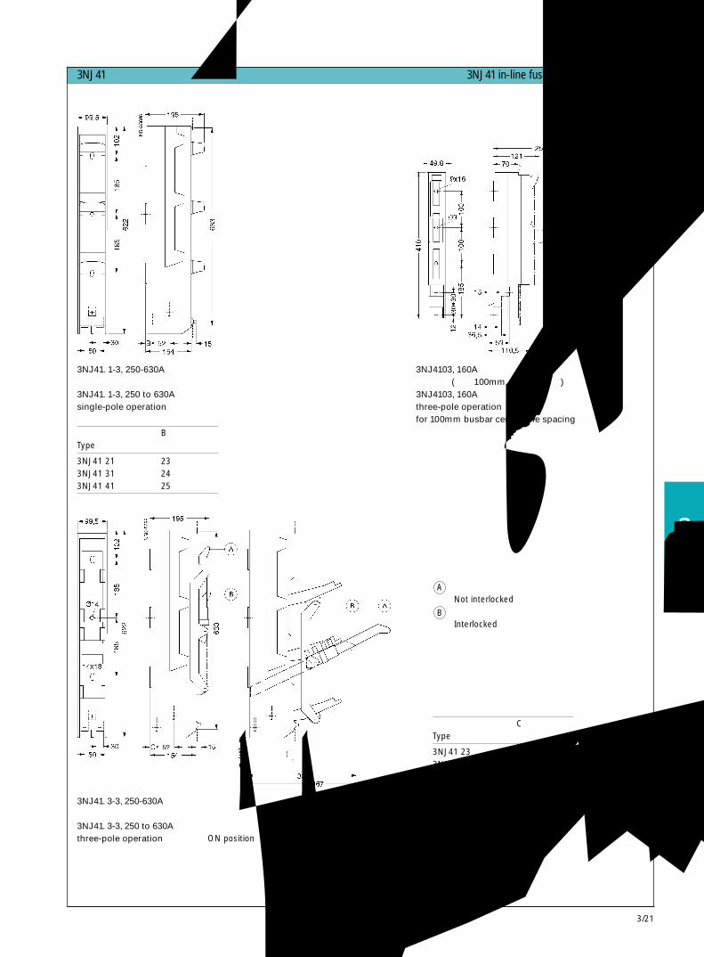
3/21
3
3NJ41 in-line fuse switch disconnectors3NJ41列式熔断器式隔离开关
隔离开关Disconnectors
3NJ41. 1-3, 250-630A单极操作3NJ41. 1-3, 250 to 630Asingle-pole operation
3NJ4103, 160A三极操作(用于 100mm中心间距母线)3NJ4103, 160Athree-pole operationfor 100mm busbar centre-line spacing
型号 BType
3NJ41 21 233NJ41 31 243NJ41 41 25
3NJ41. 3-3, 250-630A三极操作3NJ41. 3-3, 250 to 630Athree-pole operation
“接通”位置 “断开”位置ON position OFF position
型号 CType
3NJ41 23 233NJ41 33 243NJ41 43 25
不联锁Not interlocked联锁Interlocked
B
A
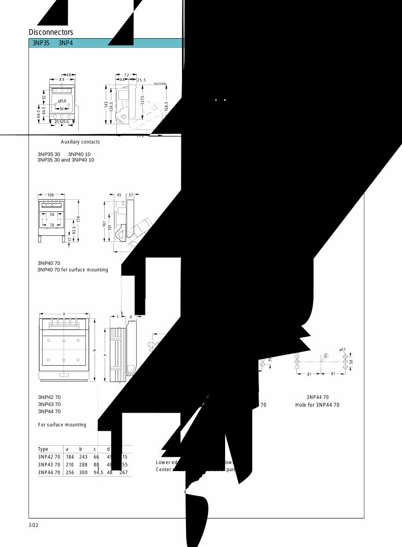
3/22
81 81
5022
6565
50
11NSK-8344NSK-8345
ø11
1146.5
85116130
2
5011
NSK-8343a
ø
108
50
70
1783
.517
0
3NP35 and 3NP4 fuse switch disconnectors3NP35与 3NP4熔断器式隔离开关
隔离开关Disconnectors
3NP35 30 和 3NP40 10
辅助触头
3NP40 70 用于表面安装
50
5.870
83.5
1
NSK
-834
2
用于 3NP40 70 的安装孔
用于 3NP42 70 的安装孔3NP42 703NP43 703NP44 70用于表面安装
用于 3NP43 70 的安装孔 用于 3NP44 70 的安装孔
① 隔离开关下部底端② 隔离开关下部中心① Lower edge of disconnector’s lower part② Center of disconnector’s lower part
Type型号 a b c d e
3NP42 70 184 243 66 45.5 215
3NP43 70 210 288 80 48 255
3NP44 70 256 300 94.5 48 267
48
25.525.5
50
5.8
5264
.5
Ø
89
44.5
143
3NP35 30 and 3NP40 10 Mounting cutout for 3NP35 30 and 3NP40 10
Auxiliary contacts
3NP40 70 for surface mounting Hole for 3NP40 70
Hole for 3NP43 70 Hole for 3NP44 70
3NP35 30 和 3NP40 10 安装切割图
Hole for 3NP42 70
126.
5
7244 25.5
127.
5
168.
5
173
SA2-5249a
143
50
M5
100
155
68
NS
1-52
72
161
101
45 37
190 NS
K-8
296a
For surface mounting
a
b
c d
e
NSK-8297a
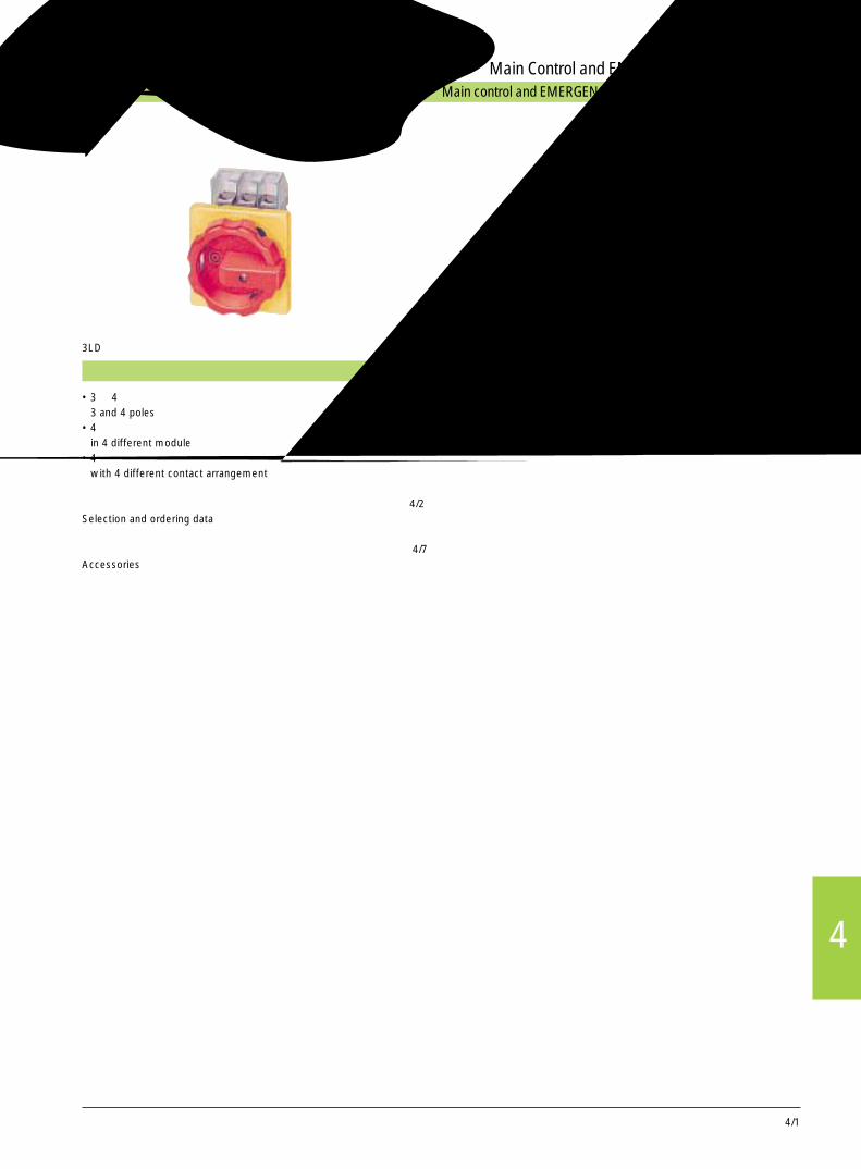
主控和急停开关,从 25A 到 125A Main control and EMERGENCY-STOP switches from 25A to 125A
主控和急停开关Main Control and EMERGENCY-STOP Switches
3LD
4/1
• 3 和 4 极3 and 4 poles
• 4 种不同模式in 4 different module
• 4 种不同触点布置方式with 4 different contact arrangement
选型及订货数据 4/2Selection and ordering data
附件 4/7Accessories
页号page
4
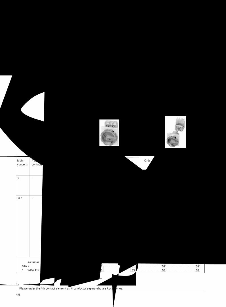
4/2
1)
1)
1)
1)
1)
1)
3LD2 可作为控制主回路或辅助回路的开关,也可用作按要求在维护的修理时开断三相电机等负载的装置。The 3LD2 switches are used to switch mainand auxiliary circuits, but also to switchthree-phase motors and other loads in theevent of maintenance and repair.
主控和急停开关 3LD23LD2 Main Control and EMERGENCY-STOP Switches 选型与订货数据 Selection and Ordering Data
触点的数量和形式 额定值Number and version Ratings atof the contacts 50...60Hz
380...440V
面板式安装主控或急停开关,带旋转动作机构在断开位置最多可用 3 把挂锁锁闭正面保护等级 IP 65
Front-mounting switchesMain control and EMERGENCY-STOPswitches with rotary actuator,lockable in 0 positionwith max. 3 padlocks.Degree of protection, front side IP 65
面板 3LD2 1, 3LD2 2: 67 x 67mm;Front cover 3LD2 5 to 3LD2 8: 90 x 90mm
基座式安装主控或急停开关,带门旋转开关带 300mm 长的开关轴可用 3 把挂锁锁闭,正面保护等级 IP 65
Base-mounting switchesMain control and EMERGENCY-STOPswitches with door-coupling rotary actuator,with 300mm switch shaftlockable with 3 padlocksDegree of protection, front side IP 65
面板 3LD2 1, 3LD2 2: 67 x 67mm;Front cover 3LD2 5 BIS 3LD2 8: 90 x 90mm
可用作• 开 / 关装置• 急停装置• 主开关符合 DIN EN 60 204 - 1 的要求They can be used as• ON/OFF switches• EMERGENCY STOP switches and• Main switches in conformity with IEC 60 204
主控和急停符合 IEC 对手动隔离开关的要求,也符合 IEC 60 204对机械操作的负荷开关的要求 60 947-3, DIN VDE 0660 Part 107。According to IEC 60 947-3/DIN VDE 0660Part 107 (EN 60 947-3), main andEMERGENCY-STOP switches are manuallyactuated switch disconnectors and meet theisolator characteristics and the requirementsof the machine guideline IEC 60 204-1.
主触点 辅助触点 功率 电流 订货号 订货号 订货号 订货号Main Aux. PI Iu Order No. Order No. Order No. Order No.contacts contacts AC-23A
kW A
3 - 9.5 25 3LD2 103-0TK.. 3LD2 154-0TK.. 3LD2 113-0TK.. 3LD2 144-0TK..11.5 32 3LD2 203-0TK.. 3LD2 254-0TK.. 3LD2 213-0TK.. 3LD2 244-0TK..22 63 3LD2 504-0TK.. 3LD2 555-0TK.. 3LD2 514-0TK.. 3LD2 545-0TK..37 100 3LD2 704-0TK.. - 3LD2 714-0TK.. -45 125 3LD2 804-0TK.. - 3LD2 814-0TK.. -
3+N - 9.5 25 3LD2 103-1TL.. 3LD2 154-1TL.. 3LD2 113-1TL.. 3LD2 144-1TL..11.5 32 3LD2 203-1TL.. 3LD2 254-1TL.. 3LD2 213-0TK.. 3LD2 244-0TK..
+ +3LD9 220-0C 3LD9 220-0C
22 63 3LD2 504-0TK.. 3LD2 555-0TK.. 3LD2 514-0TK.. 3LD2 545-0TK.. + + + + 3LD9 250-0B 3LD9 250-0B 3LD9 250-0C 3LD9 250-0C
37 100 3LD2 704-0TK.. - 3LD2 714-0TK.. - + + 3LD9 280-0B 3LD9 280-0C
45 125 3LD2 804-0TK.. - 3LD2 814-0TK.. - + + 3LD9 280-0B 3LD9 280-0C
1) 第四极 N 线控制,请另订货,参见附件。Please order the 4th contact element as N conductor separately; see Accessories.
旋钮头 /Actuator黑 /black红 /黄 red/yellow (急停 /Emergency stop)
3LD2 203-0TK53 3LD2 213-0TK53
1)
1)
1)
1)
5153
5153
5153
5153
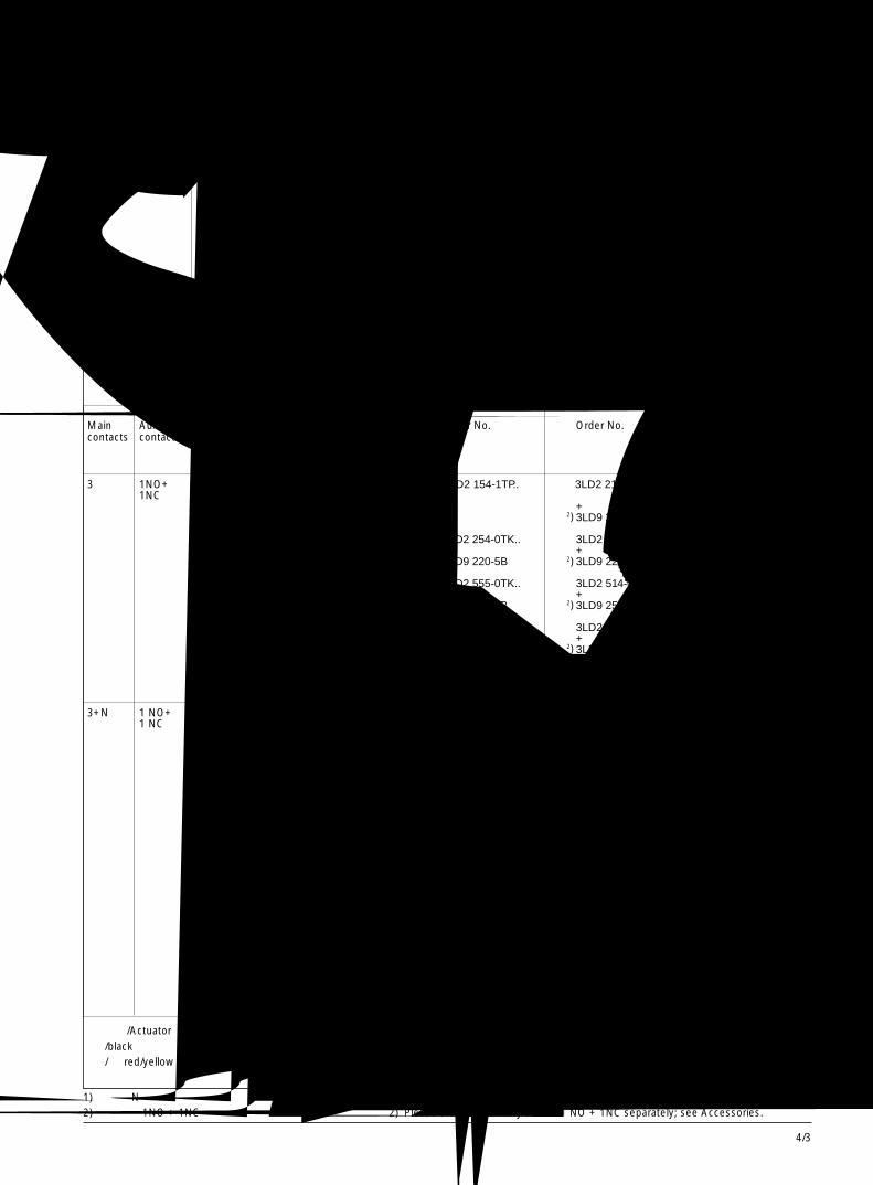
4/3
4
2)
1)
2)
1)
2)
1)
2)
2)
2)
2)
2)
2)
1)
2)
2)
2)
1)
2)
1)
2)
2)
2)
2)
2)
2)
2)
1)
2)
1)
2)
2)
2)
2)
2)
选型与订货数据 Selection and Ordering Data
1) 第四极 N 线控制,请另订货,参见附件。 1) Please order the 4th contact element as N conductor separately; see Accessories.2) 辅助触点 1NO + 1NC 请另订货,参见附件。 2) Please order an auxiliary switch 1 NO + 1NC separately; see Accessories.
触点的数量和形式 额定值Number and version Ratings atof the contacts 50...60Hz
380...440V
面板式安装主控或急停开关,带旋转动作机构断开位置最多可用 3 把挂锁锁闭正面保护等级 IP 65
Front-mounting switchesMain control and EMERGENCY-STOPswitches with rotary actuator,lockable in 0 positionwith max. 3 padlocks.Degree of protection, front side IP 65
面板 3LD2 1, 3LD2 2: 67 x 67mm;Front cover 3LD2 5 bis 3LD2 8: 90 x 90mm
基座式安装主控或急停开关,带门旋转开关带 300mm 长的开关轴可用 3 把挂锁锁闭,正面保护等级 IP 65
Base-mounting switchesMain control and EMERGENCY-STOPswitches with door-coupling rotary actuatorwith 300 mm switch shaft,lockable in 0 positionwith max. 3 padlocks.Degree of protection, front side IP 65
面板 3LD2 1, 3LD2 2: 67 x 67mm;Front cover 3LD2 5 BIS 3LD2 8: 90 x 90mm
3LD2 203-0TK53 3LD2 213-0TK53
主触点 辅助触点 功率 电流 订货号 订货号 订货号 订货号Main Aux. PI Iu Order No. Order No. Order No. Order No.contacts contacts AC-23A
kW A
3 1NO+ 9.5 25 3LD2 103-1TP.. 3LD2 154-1TP.. 3LD2 213-0TK.. 3LD2 144-0TK..1NC
+ + 3LD9 220-5C 3LD9 220-5C
11.5 32 3LD2 203-0TK.. 3LD2 254-0TK.. 3LD2 213-0TK.. 3LD2 244-0TK.. + + + + 3LD9 220-5B 3LD9 220-5B 3LD9 220-5C 3LD9 220-5C
22 63 3LD2 504-0TK.. 3LD2 555-0TK.. 3LD2 514-0TK.. 3LD2 545-0TK.. + + + + 3LD9 250-5B 3LD9 250-5B 3LD9 250-5C 3LD9 250-5C
37 100 3LD2 704-0TK.. - 3LD2 714-0TK.. - + + 3LD9 280-5B 3LD9 280-5C
45 125 3LD2 804-0TK.. - 3LD2 814-0TK.. - + + 3LD9 280-5B 3LD9 280-5C
3+N 1 NO+ 9.5 25 3LD2 103-2EP.. 3LD2 154-2EP.. 3LD2 113-1TL.. 3LD2 144-1TL..1 NC
+ + 3LD9 220-5C 3LD9 220-5C
11.5 32 3LD2 203-1TL.. 3LD2 254-1TL.. 3LD2 213-0TK.. 3LD2 224-0TK.. + + + + 3LD9 220-0B 3LD9 220-5B 3LD9 220-0C 3LD9 220-0C
+ + 3LD9 250-5C 3LD9 220-5C
22 63 3LD2 504-0TK.. 3LD2 555-0TK.. 3LD2 514-0TK.. 3LD2 545-0TK.. + + + + 3LD9 250-0B 3LD9 250-0B 3LD9 250-0C 3LD9 250-0C + + + + 3LD9 250-5B 3LD9 250-5B 3LD9 250-5C 3LD9 250-5C
37 100 3LD2 704-0TK.. - 3LD2 714-0TK.. - + + 3LD9 280-0B 3LD9 280-0C + + 3LD9 280-5B 3LD9 280-5C
45 125 3LD2 804-0TK.. - 3LD2 814-0TK.. - + + 3LD9 280-0B 3LD9 280-0C + + 3LD9 280-5B 3LD9 280-5C
主控和急停开关 3LD23LD2 Main Control and EMERGENCY-STOP Switches
旋钮头 /Actuator黑 /black红 / 黄 red/yellow (急停 / Emergency stop)
1)
2)
1)
2)
5153
5153
5153
5153
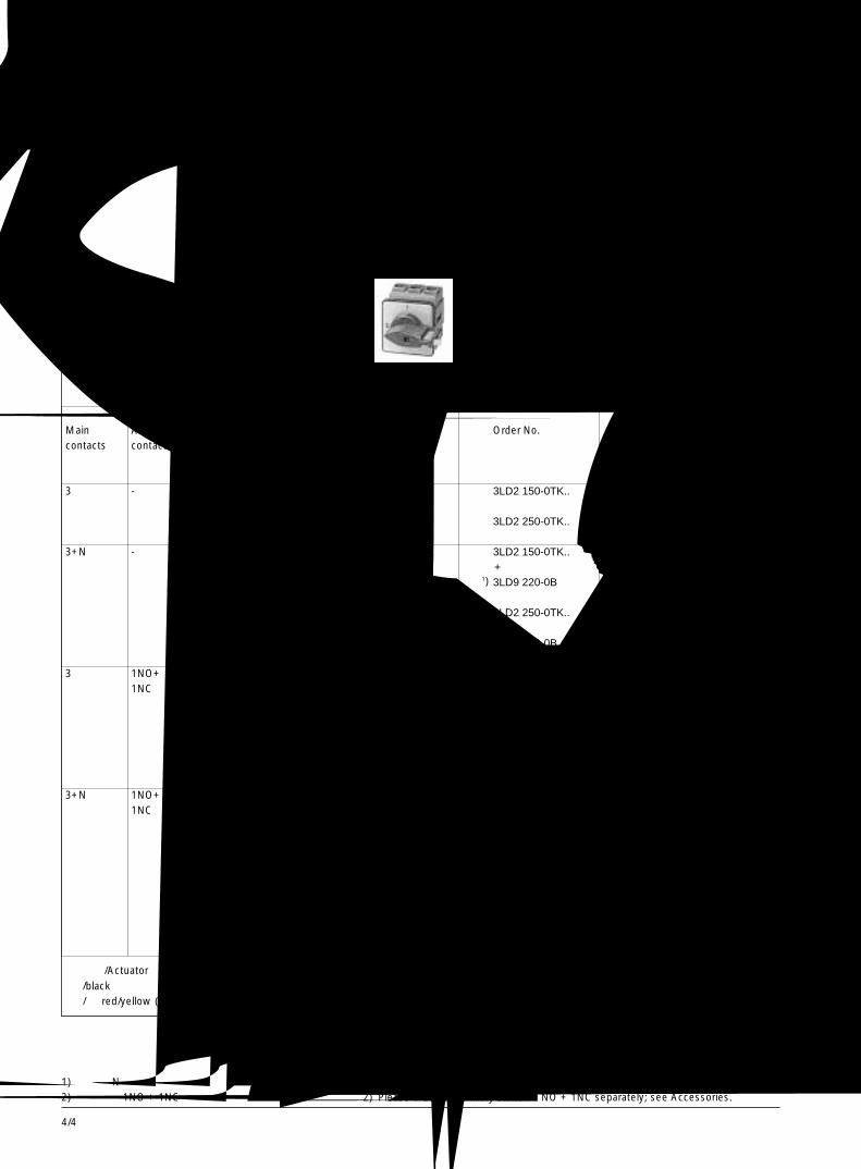
4/4
2)
1)
2)
1)
2)
1)
1)
2)
2)
1)
2)
1)
2)
1)
1)
2)
旋钮头 /Actuator黑 /black红 / 黄 red/yellow (急停 /Emergency stop )
主触点 辅助触点 功率 电流 订货号 订货号Main Aux. PI Iu Order No. Order No.contacts contacts AC-23A
kW A3 - 9.5 25 3LD2 122-0TK.. 3LD2 150-0TK..
11.5 32 3LD2 222-0TK.. 3LD2 250-0TK..
3+N - 9.5 25 3LD2 122-0TK.. 3LD2 150-0TK.. + + 3LD9 220-0B 3LD9 220-0B
11.5 32 3LD2 222-0TK.. 3LD2 250-0TK.. + + 3LD9 220-0B 3LD9 220-0B
3 1NO+ 9.5 25 3LD2 122-0TK.. 3LD2 150-0TK..1NC + +
3LD9 220-5B 3LD9 220-5B
11.5 32 3LD2 222-0TK.. 3LD2 250-0TK.. + + 3LD9 220-5B 3LD9 220-5B
3+N 1NO+ 9.5 25 3LD2 122-0TK.. 3LD2 150-0TK..1NC + +
3LD9 220-0B 3LD9 220-0B + + 3LD9 220-5B 3LD9 220-5B
11.5 32 3LD2 222-0TK.. 3LD2 250-0TK.. + + 3LD9 220-0B 3LD9 220-0B + + 3LD9 220-5B 3LD9 220-5B
选型与订货数据 Selection and Ordering Data面板式安装主控或急停开关,带旋转动作机构断开位置最多可用 2 把挂锁锁闭正面保护等级 IP 65Front-mounting switchesMain control and EMERGENCY-STOP switcheswith knob actuator,lockable in 0 positionwith max. 2 padlocks.Degree of protection, front side IP 65
面板 / Front cover 48 x 48mm
触点的数量和形式 额定值Number and version Ratings atof the contacts 50...60Hz
380...440V
1) 第四极 N 线控制,请另订货,参见附件。 1) Please order the 4th contact element as N conductor separately; see Accessories.2) 辅助触点 1NO + 1NC 请另订货,参见附件。 2) Please order an auxiliary switch 1 NO + 1NC separately; see Accessories.
3LD2 222-0TK11
主控和急停开关 3LD23LD2 Main Control and EMERGENCY-STOP Switches
1113
1113
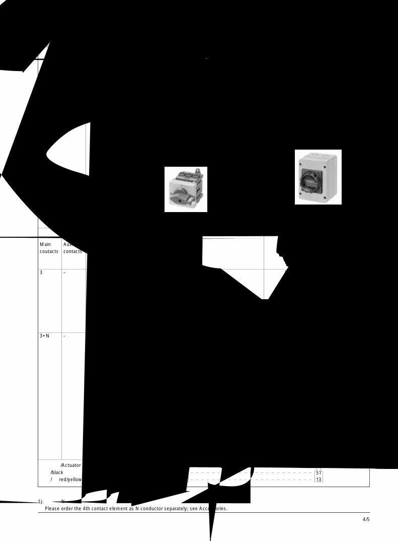
4/5
4
旋钮头 /Actuator黑 /black红 / 黄 red/yellow (急停 /Emergency stop)
1)
1)
1)
1)
1)
1)
1)
主触点 辅助触点 功率 电流 订货号 订货号Main Aux. PI Iu Order No. Order No.coutacts contacts AC-23A
kW A3 - 9.5 25 3LD2 130-0TK.. 3LD2 161-0TB..
11.5 32 3LD2 230-0TK.. 3LD2 261-0TB..
22 63 3LD2 530-0TK.. 3LD2 562-0TB..
37 100 3LD2 730-0TK.. 3LD2 763-0TB..
45 125 3LD2 830-0TK.. 3LD2 863-0TB..3+N - 9.5 25 3LD2 130-0TK.. 3LD2 161-1TC..
+ 3LD9 220-0C
11.5 32 3LD2 230-0TK.. 3LD2 261-1TC53 + 3LD9 220-0C
22 63 3LD2 530-0TK.. 3LD2 562-1TC53 + 3LD9 250-0C
37 100 3LD2 730-0TK.. 3LD2 763-0TB.. + + 3LD9 280-0C 3LD9 280-0C
45 125 3LD2 830-0TK.. 3LD2 863-0TB.. + + 3LD9 280-0C 3LD9 280-0C
选型与订货数据 Selection and Ordering Data
1) 第四极 N 线控制,请另订货,参见附件。 Please order the 4th contact element as N conductor separately; see Accessories.
塑壳开关带N, PE 线夹端子主控或急停开关可在断开位置最多用 3 把挂锁锁闭正面保护等级 IP 65
Switches with insulatingmaterial enclosure with N/PE terminalMain control and EMERGENCY-STOPswitches,lockable in 0 positionwith max. 3 padlocks.Degree of protection: IP 65
触点的数量和形式 额定值Number and version Ratings atof the contacts 50...60Hz
380...440V
开关装于配电柜内用螺丝或卡入式装于 35mm 导轨上开 /关或急停,带面板和控制手柄可在断开位置最多用 2 把挂锁锁闭,正面保护等级 IP 44
Switches for distributionboard installation, withscrew or snap mounting on35 mm DIN railON-OFF and EMERGENCY-STOP switcheswith masking frame and knob,lockable in 0 positionwith max. 2 padlocks.Degree of protection,front side IP 44
3LD2 530-0TK13 3LD2 261-0TB51
主控和急停开关 3LD23LD2 Main Control and EMERGENCY-STOP Switches
1113
5113

4/6
1)
1)
1)
1)
1)
2)
1)
2)
1)
2)
1)
2)
2)
1)
旋钮头 /Actuator黑 /black红 /黄 red/yellow (急停 /Emergency stop)
主触点 辅助触点 功率 电流 订货号 订货号Main Aux. PI Iu Order No. Order No.coutacts contacts AC-23A
kW A3 1NO+ 9.5 25 3LD2 130-0TK.. 3LD2 161-1GP..
1NC + 3LD9 220-5C
11.5 32 3LD2 230-0TK.. 3LD2 261-1GP.. + 3LD9 220-5C
22 63 3LD2 530-0TK.. 3LD2 562-1GP.. + 3LD9 250-5C
37 100 3LD2 730-0TK.. 3LD2 763-1GP.. + 3LD9 280-5C
45 125 3LD2 830-0TK.. 3LD2 863-1GP.. + 3LD9 280-5C
3+N 1NO+ 9.5 25 3LD2 130-0TK.. 3LD2 161-1GP..1NC + +
3LD9 220-5C 3LD9 220-0C + 3LD9 220-0C
11.5 32 3LD2 230-0TK.. 3LD2 261-1GP.. + + 3LD9 220-5C 3LD9 220-0C + 3LD9 220-0C
22 63 3LD2 530-0TK.. 3LD2 562-1GP.. + + 3LD9 250-5C 3LD9 250-0C + 3LD9 250-0C
37 100 3LD2 730-0TK.. 3LD2 763-1GP.. + + 3LD9 280-5C 3LD9 280-0C +
3LD9 280-0C45 125 3LD2 830-0TK.. 3LD2 863-1GP..
+ + 3LD9 280-5C 3LD9 280-0C + 3LD9 280-0C
触点的数量和形式 额定值Number and version Ratings atof the contacts 50...60Hz
380...440V
3LD2 530-0TK11 3LD2 261-0GP53
选型与订货数据 Selection and Ordering Data
主控和急停开关 3LD23LD2 Main Control and EMERGENCY-STOP Switches
塑壳开关带N, PE 线夹端子主控或急停开关可在断开位置最多用 3 把挂锁锁闭正面保护等级 IP 65
Switches with insulatingmaterial enclosure with N/PE terminalMain control and EMERGENCY-STOPswitches,lockable in 0 position with max. 3 padlocks.Degree of protection: IP 65
开关装于配电柜内用螺丝或卡入式装于 35mm 导轨上开 /关或急停,带面板和控制手柄可在断开位置最多用 2 把挂锁锁闭,正面保护等级 IP 44
Switches for distributionboard installation, withscrew or snap mounting on35 mm DIN railON-OFF and EMERGENCY-STOP switcheswith masking frame and knob,lockable in 0 position with max. 2 padlocks.Degree of protection,front side IP 44
1) 第四极 N 线控制,请另订货,参见附件。 1) Please order the 4th contact element as N conductor separately; see Accessories.2) 辅助触点 1NO + 1NC 请另订货,参见附件。 2) Please order an auxiliary switch 1 NO + 1NC separately; see Accessories.
2)
2)
2)
2)
2)
1)
1113
5153
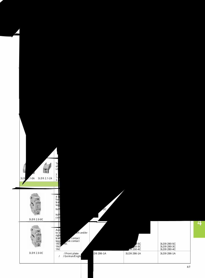
4/7
4
面板安装的附件 Accessories for front mounting
Accessories for front or base mounting
订货号 订货号 订货号Order No. Order No. Order No.
第 4极 触点 (常闭) 3LD9 220-0B 3LD9 250-0B 3LD9 280-0B用于正面安装提前闭合,滞后分断4th contact (N conductor)for front installationleading make contactlagging break contact
N/PE 端子 3LD9 220-2B 3LD9 250-2B 3LD9 280-2B穿透式 N/PEN/PE terminal blockcontinuous
辅助触点装于左侧或右侧提前分断,滞后闭合Auxiliary switchto be fitted at the left and/orright hand sidelagging make contactleading break contact1NO+1NC 3LD9 220-5B 3LD9 250-5B 3LD9 280-5B1NO 3LD9 220-3B 3LD9 250-3B 3LD9 280-3B1NC 3LD9 220-4B 3LD9 250-4B 3LD9 280-4B
前面板 / Front plate 3LD9 286-1A 3LD9 286-1A 3LD9 286-1A德 / 英 / German/English
旋转把手断开位置最多可用 3 把挂锁锁闭Rotary actuatorlockable in 0 positionwith max. 3 padlocks
用于 4 孔固定for 4-hole fixing黑 /black 3LD9 224-1B 3LD9 284-1B 3LD9 284-1B红 /red / 黄 /yellow 3LD9 224-3B 3LD9 284-3B 3LD9 284-3B
用于中心孔固定for central hole fixing黑 /black 3LD9 224-1D 3LD9 284-1D -红 /red / 黄 /yellow 3LD9 224-3D 3LD9 284-3D -
前面板 / Front plate 3LD9 286-1A 3LD9 286-1A 3LD9 286-1A德 / 英 / German/English
端子盖,用作额外触电保护装于上部或下部Terminal cover as additionalshock hazard protectionsnaps on at top and bottom单极 1 pole3 极 3 pole1-pole (1 pack = 4 units) 3LD9 221-2A 3LD9 251-2A 3LD9 281-2A3-pole (1 pack = 4 units) 3LD9 221-0A 3LD9 251-0A -
第 4极 触点 (N 导体) 3LD9 220-0C 3LD9 250-0C 3LD9 280-0C用于背面安装提前闭合,滞后分断4 contact (N conductor)for rear installationleading make contactlagging break contact
N/PE 端子 3LD9 220-2C 3LD9 250-2C 3LD9 280-2C穿透式 N/PEN/PE terminal blockcontinuous
辅助触点装于左右两侧提前闭合,滞后分断Auxiliary switchto be fitted at the left and/orright hand sideleading make contactlagging break contact1NO+1NC 3LD9 220-5C 3LD9 250-5C 3LD9 280-5C1NO 3LD9 220-3C 3LD9 250-3C 3LD9 280-3C1NC 3LD9 220-4C 3LD9 250-4C 3LD9 280-4C
前面板 / Front plate 3LD9 286-1A 3LD9 286-1A 3LD9 286-1A德 / 英 / German/English
Accessories for base or mounting and distribution boards
3LD9 2.0-2B
3LD9 2.0-5B
3LD9 2.4-1D
3LD9 2.0-3B
3LD9 2.1-2A3LD9 2.1-0A
3LD9 2.0-0B
3LD9 2.0-0C
3LD9 2.0-0C
主控和急停开关 3LD23LD2 Main Control and EMERGENCY-STOP Switches
基座或柜内安装的附件
面板式基座式安装的附件

4/8
备注For your notes

4/9
4
备注For your notes

4/10
备注For your notes