Embed Size (px)
Citation preview
20世紀の歴史的構造物The historic structure of The 20th century 20世紀の歴史的構造物
20世紀の歴史的構造物The historic structure of The 20th century
"Steel Citadel" TEKKO KAIKAN— Evolutional architecture with advanced various steel material —
Teizo Amano NIKKEN SEKKEI Construction Management, Inc. Mitsuo Uchida NIKKEN SEKKEI LTD.
In 1966 (Showa 41), Japan’s population topped one hundred million. Its economy grew out of post war economic recovery and aimed to make a further breakthrough following great nations. Interestingly, in the same year, two buildings were completed: Keidanren Kaikan-the “castle” of Japan Business Federation), which promoted reconstruction and restoration of Japan’s economy –and TEKKO KAIKAN-“Steel Citadel” of steel industry, which always led industries. In particular, TEKKO KAIKAN was built with the latest constructional materials, such as large diameter tube truss steel structure, stainless steel, which was a new building material in those days, anticorrosion steel applied for everywhere. It was like an exhibition pavilion of steel. The details of the establishment of TEKKO KAIKAN and the points of the design and construction of the building is introduced by NIKKEN SEKKEI’s Mr. Teizo Amano and Mr. Mitsuo Uchida, who were in charge of the design and supervision of TEKKO KAIKAN.
1. Details of the Establishment ofTEKKOKAIKAN
The former managing director of TEKKO KAIKAN, Haruhiko Kozakai, stated about the details of the establishment of TEKKO KAIKAN;
“Steel industry, which led the post war economic growth, grew and developed further in 1955 (Showa 30). In 1959 (Showa 34), various industrial activities were taken. As a result, they found ”Kozai Club Building” small and started to consider about a new steel complex building.
Based on the decision of the board of directors of Kozai Club (present-day The Japan Iron and Steel Federation), they decided to build a new steel complex building, which would be a new place for cooperation of industry and an appropriate place for steel industry, on the site of “Kozai Club Building”. In order to promote the construction, “Kozai Club Building Governing Board” was founded, and it was started toward the realization at the center of this Governing Board.
Later, in 1961 (Showa 36), “TEKKO KAIKAN
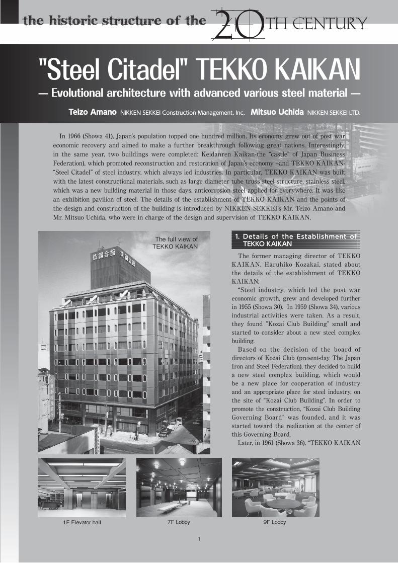
1F Elevator hall 7F Lobby 9F Lobby
The full view of TEKKO KAIKAN
1
20世紀の歴史的構造物
The historic structure of the 20th century
Ltd.” was founded. The study was made under “TEKKO KAIKAN Construction Promotion Committee” and later “KAIKAN Construction Committee” from the planning and the drawing up of the building to the completion in 1966 (Showa 41). It was supposed to aim to build a building which is appropriate as a Steel Citadel with the best facilities.
Mr. Yoshihiro Inayama , the managing director (at that time) of Yawata Iron & Steel Co., Ltd, who was the administrative director of Kozai Club at that time and the first president of TEKKO KAIKAN is said to have had a great eagerness and contribution to the construction of TEKKO KAIKAN.”
NIKKEN SEKKEI was in charge of the design and the supervision of TEKKO KAIKAN and SHIMIZU CORPORATION was in charge of the construction.
2.DriftoftheDesign
The design of TEKKO KAIKAN was based on the basic concept that this is a common facility
for steel industry and that the building itself symbolizes steel and is an architectural building that specifically shows it. They aimed to build a building which can be used for multi-purposes such as business office, conference room, restaurant and parking area in an L-shaped area alongside a narrow three-sided road with a strict setback regulation, realizing functionality and planning with convenience and high service performance, appropriate facility design, and interior design for “place for industry cooperation”. In particular, by design in which the features of steel materials mainly made of iron and stainless were utilized, they aimed to build a distinguishing building which is appropriate for the name of TEKKO KAIKAN.
In production and construction, with col laborat ion with steel industry, they under took the production and construction with the latest steel materials and methods at the time. One of the characteristic was in that steel production, such as stainless, was used not only for the
structure but also for the exterior, the interior, the facility, the furniture and the decorations.
3.Pointof theArchitecturalPlan
Meeting requirements f rom Constriction Committee, it was the point of the construction plan to make a planning that can be used for multi-purposes and can be used as a common facility for the industry.3.1 Floor Plan. Creating an Astylar
Large Space by Large Diameter Steel Beam
From 1st to 5th f loors have business offices for the industry-related groups. From 6th to 8th floors have small-size, middle-size and large-size rent conference rooms. The 9th floor has restaurants and salon. From the 3rd basement to the 1st basement have parking area and machine rooms. One feature is that the 1st floor has a wide lobby and the conference rooms were designed to be used for many purposes, such as business conference, lecture workshop, tra ining workshop, social party and wedding party. In particular, the restaurant is an astylar large space with 465m2, showing lozenge shaped grid beams made with large diameter steel tubes.3.2 Exterior Plan. A New Facade
by Stainless PanelsFor the exterior, which is the face
of TEKKO KAIKAN, they adopted a stainless curtain wall. In making this curtain wall unit, they needed to avoid distortion resulting from welding, uniform hairline finish, ensure water-proof performance of the jointed parts. And also, the expression of rounded windows features a design to provide the image of the latest all-stainless trains.3.3 I n t e r i o r P l a n . V a r i o u s
Expressions by Making the Best Use of Stainless
As for the interior, they had an interior plan appropriate for each
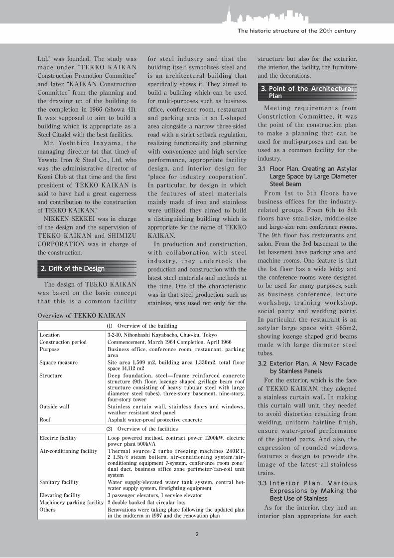
(1) Overview of the buildingLocation 3-2-10, Nihonbashi Kayabacho, Chuo-ku, TokyoConstruction period Commencement, March 1964 Completion, April 1966Purpose Business office, conference room, restaurant, parking
areaSquare measure Site area 1,509 m2, building area 1,330m2, total floor
space 14,112 m2Structure Deep foundation, steel—frame reinforced concrete
structure (9th floor, lozenge shaped grillage beam roof structure consisting of heavy tubular steel with large diameter steel tubes), three-story basement, nine-story, four-story tower
Outside wall Stainless curtain wall, stainless doors and windows, weather resistant steel panel
Roof Asphalt water-proof protective concrete(2) Overview of the facilities
Electric facility Loop powered method, contract power 1200kW, electric power plant 500kVA
Air-conditioning facility Thermal source/2 turbo freezing machines 240RT, 2 1.5h/t steam boilers, air-conditioning system/air-conditioning equipment 7-system, conference room zone/dual duct, business office zone perimeter/fan-coil unit system
Sanitary facility Water supply/elevated water tank system, central hot-water supply system, firefighting equipment
Elevating facility 3 passenger elevators, 1 service elevatorMachinery parking facility 2 double banked flat circular lotsOthers Renovations were taking place following the updated plan
in the midterm in 1997 and the renovation plan
Overview of TEKKO KAIKAN
2
The historic structure of the 20th century
use of the room. They also used materials in various ways; stainless copper plates were processed to give expression to the material and used to finish main parts. In particular, they used stainless copper plates for the decorative panels for the lobby, the hall and the conference rooms, the door and inside panels of the elevators, the decorative frame of lighting equipment, decorative relief with polishing, etching, folding in order to make interior have various expressions in the use of high technologies in those days, aiming at high quality construction.
4.OverviewofStructuralPlan
They made changes in the structural plan three times and decided on the final plan, which is the present one.
According to the f irst plan , taking the location conditions into account, they proposed a three-story basement and nine-story reinforced concrete structure in a conventional method which is a combination of new steel materials only with shape steel of iron frame material (role H-shaped steel, T bur, honeycomb H-shaped steel) . In regards to t h i s pla n , TEKKO KAIKAN Construction Committee made the following requirement. “The building should be innovative and symbolic of new steel materials, while it is appropriate for the name of TEKKO industry, which is the founder.”
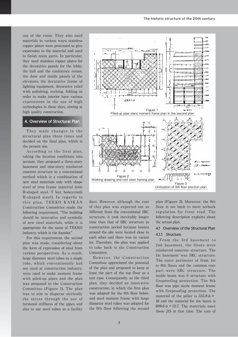
For this requirement, the second plan was made, considering about the form of expression of steel from various perspectives. As a result, large diameter steel tubes as a single tube, which conventionally had not used at construction industry, were used to make moment frame with piled-up pipes and the plan was proposed to the Construction Committee (Figure 1). The plan was to aim to disperse sterically the stress through the use of torsional stiffness of the pipes and also to use steel tubes as a facility
duct. However, although the cost of this plan was expected not so different from the conventional SRC structure, it took inevitably longer time than that of SRC structure in construction period because houses around the site were located close to each other and there was no vacant lot. Therefore, the plan was applied to take back to the Construction Committee.
However, t he Const ruct ion Committee appreciated the potential of the plan and proposed to keep at least the part of the top floor as a test case. Consequently, as the third plan, they decided an innovative construction, in which the first plan was adopted for the 8th floor below, and steel moment frame with large diameter steel tubes was adopted for the 9th floor following the second
plan (Figure 2). Moreover, the 9th floor is set back to meet setback regulation for front road. The following description explains about the actual plan.4.1 Overview of the Structural Plan4.1.1 Structure
From the 3rd ba sement to 2nd basement , the f loors were reinforced concrete structure. The 1st basement was SRC structure. The outer perimeter of from 1st to 8th floors and the common core part were SRC structure. The inside beam was S structure with fireproofing protection. The 9th floor was pipe steric moment frame with fireproofing protection. The material of the pillar is 555.8φ×16 and the material for the beam is 609.6φ×12.7. The materials meet those JIS at that time. The core of
Figure 1Piled-up pipe steric moment frame plan in the second plan
Figure 3 Unitization of 9th floor erection plan
Figure 2 Working drawing and roof steel framing plan
3
20世紀の歴史的構造物
The historic structure of the 20th century
the tower was RC 4-story structure. Lightweight concrete was poured on the S structure part of the floorboard, which was VA-shaped deck plate Oshima ballasting, and field connection was performed with JIS high-strength bolts (F9T). The pipes were welded as full penetration welding joint whether they were weld at that site or at factories. 4.1.2 Used Steel Materials for the
StructureReinforced thin bars met current
SR235. Main reinforced bars met current SD345, which was accepted by the minister at that time. For steel materia ls were used CT and T bar, for steel panels were used current SM490A, for beam honeycomb H were used SS400, and for pipes were used current STK400.4.2 Overview of the Construction
of Pipe Structure in 9th FloorSteel materials in the part of
pipe structure in the 9th floor were used current STK400. The total amount was approximately 100t. As shown in Figure 3, they were made at factories in consideration of the unitization for erection plan. In making them, they carefully planned the unitization and the welding details and controlled the accuracy of the production.
Additionally, construction of pipe structure in the 9th floor was done to minimize the errors arising from erecting steel frame to the 9th floor and avoid interfering with the upper pipe construction because erection was performed on the floor beam at the 9th floor. Particularly, they needed to be careful about the lozenge shaped grid beam structure with large diameter steel tubes, which did not have any previous example.4.2.1 Pipes Weld Joint
They made the joint of the pipes easy. Unit had the maximum length and width for transportation. They tried to minimize the number of weld joint at the site. Also, panel unit for the construction was width
3.0m and length 13.0m, taking into account of the site conditions and the size possible to transport in the night time. The unitization is as shown in Figure 3 described above.
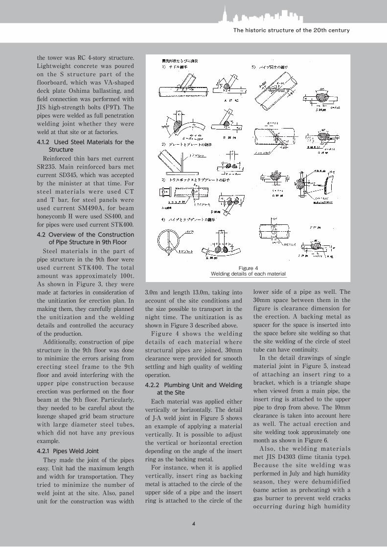
Figure 4 shows the welding details of each material where structural pipes are joined, 30mm clearance were provided for smooth settling and high quality of welding operation.4.2.2 Plumbing Unit and Welding
at the SiteEach material was applied either
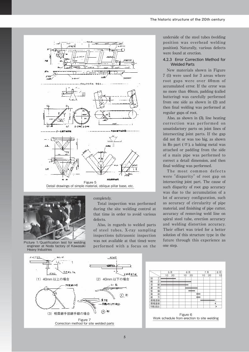
vertically or horizontally. The detail of J-A weld joint in Figure 5 shows an example of applying a material vertically. It is possible to adjust the vertical or horizontal erection depending on the angle of the insert ring as the backing metal.
For instance, when it is applied vertically, insert ring as backing metal is attached to the circle of the upper side of a pipe and the insert ring is attached to the circle of the
lower side of a pipe as well. The 30mm space between them in the figure is clearance dimension for the erection. A backing metal as spacer for the space is inserted into the space before site welding so that the site welding of the circle of steel tube can have continuity.
In the detail drawings of single material joint in Figure 5, instead of attaching an insert ring to a bracket, which is a triangle shape when viewed from a main pipe, the insert ring is attached to the upper pipe to drop from above. The 10mm clearance is taken into account here as well. The actual erection and site welding took approximately one month as shown in Figure 6.
Also , the welding materia ls met JIS D4303 (lime titania type). Because the site welding was performed in July and high humidity season, they were dehumidified (same action as preheating) with a gas burner to prevent weld cracks occurring during high humidity
Figure 4Welding details of each material
4
The historic structure of the 20th century
completely.Total inspection was performed
during the site welding control at that time in order to avoid various defects.
Also, in regards to welded parts of steel tubes , X-ray sampling inspections (ultrasonic inspection was not available at that time) were performed with a focus on the
underside of the steel tubes (welding position was overhead welding position). Naturally, various defects were found at erection.4.2.3 Error Correction Method for
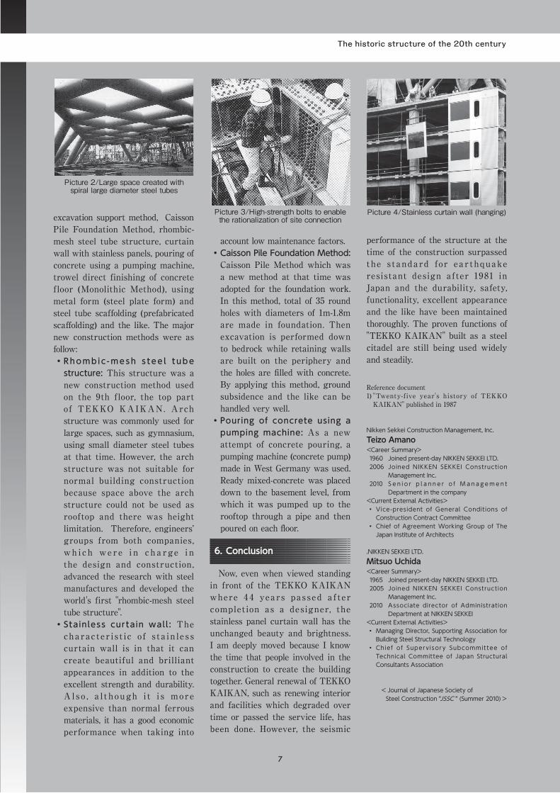
Welded PartsNew materials shown in Figure
7 (1) were used for 3 areas where root gaps were over 40mm of accumulated error. If the error was no more than 40mm, padding (called buttering) was carefully performed from one side as shown in (2) and then final welding was performed at regular gaps of root.
Also, as shown in (3), line heating correct ion was per formed on unsatisfactory parts on joint lines of intersecting joint parts. If the gap did not fit or was too big, as shown in Ro part ( ロ ), a baking metal was attached or padding from the side of a main pipe was performed to correct a detail dimension, and then final welding was performed.
The most common de fec t s were "disparity" of root gap on intersecting joint part. The cause of such disparity of root gap accuracy was due to the accumulation of a lot of accuracy configuration, such as accuracy of circularity of pipe material, and finishing of pipe cutter, accuracy of removing weld line on spiral steel tube, erection accuracy and welding distortion accuracy. Their effort was tried for a better solution of this structure type in the future through this experience as one step.
Figure 5Detail drawings of simple material, oblique pillar base, etc.
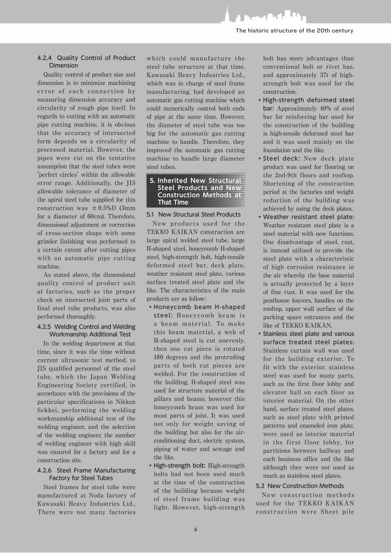
Picture 1/Qualification test for welding engineer at Noda factory of Kawasaki Heavy Industries
Figure 7Correction method for site welded parts
(1)40mm以上の場合 (2)40mm以下の場合
(3)相貫継手部継手線の場合 Figure 6Work schedule from erection to site welding
加 工
5月 6月 7月 8月10 20 10 20 10 20 10
組 立溶 接塗 料仮 組発 送建 方現場溶接現場塗装作業台除去
5
20世紀の歴史的構造物
The historic structure of the 20th century
4.2.4 Quality Control of Product Dimension
Quality control of product size and dimension is to minimize machining er ror of each connect ion by measuring dimension accuracy and circularity of rough pipe itself. In regards to cutting with an automatic pipe cutting machine, it is obvious that the accuracy of intersected form depends on a circularity of processed material. However, the pipes were cut on the tentative assumption that the steel tubes were "perfect circles" within the allowable error range. Additionally, the JIS allowable tolerance of diameter of the spiral steel tube supplied for this construction was ±0.5%D (3mm for a diameter of 60cm). Therefore, dimensional adjustment or correction of cross-section shape with some grinder finishing was performed to a certain extent after cutting pipes with an automatic pipe cutting machine.
As stated above, the dimensional quality control of product unit at factories, such as the proper check on intersected joint parts of final steel tube products, was also performed thoroughly.4.2.5 Welding Control and Welding
Workmanship Additional TestIn the welding department at that
time, since it was the time without current ultrasonic test method, to JIS qualified personnel of the steel tube, which the Japan Welding Engineering Society certified, in accordance with the provisions of the particular specifications in Nikken Sekkei, performing the welding workmanship additional test of the welding engineer, and the selection of the welding engineer, the number of welding engineer with high skill was ensured for a factory and for a construction site. 4.2.6 Steel Frame Manufacturing
Factory for Steel TubesSteel frames for steel tube were
manufactured at Noda factory of Kawasaki Heavy Industries Ltd., There were not many factories
which could manufacture the steel tube structure at that time. Kawasaki Heavy Industries Ltd., which was in charge of steel frame manufacturing, had developed an automatic gas cutting machine which could numerically control both ends of pipe at the same time. However, the diameter of steel tube was too big for the automatic gas cutting machine to handle. Therefore, they improved the automatic gas cutting machine to handle large diameter steel tubes.
5.InheritedNewStructuralSteel Products andNewConstructionMethodsatThatTime
5.1 New Structural Steel ProductsNew products used for the
TEKKO KAIKAN construction are large spiral welded steel tube, large H-shaped steel, honeycomb H-shaped steel, high-strength bolt, high-tensile deformed steel bar, deck plate, weather resistant steel plate, various surface treated steel plate and the like. The characteristics of the main products are as follow:• Honeycomb beam H-shaped
s teel : Honeycomb beam is a beam mater ia l . To make this beam material, a web of H-shaped steel is cut unevenly, then one cut piece is rotated 180 degrees and the protruding parts of both cut pieces are welded. For the construction of the building, H-shaped steel was used for structure material of the pillars and beams, however this honeycomb beam was used for most parts of joist. It was used not only for weight saving of the building but also for the air-conditioning duct, electric system, piping of water and sewage and the like.
• High-strength bolt: High-strength bolts had not been used much at the time of the construction of the building because weight of steel frame building was light. However, high-strength
bolt has more advantages than conventional bolt or rivet has, and approximately 37t of high-strength bolt was used for the construction.
• High-strength deformed steel bar: Approximately 40% of steel bar for reinforcing bar used for the construction of the building is high-tensile deformed steel bar and it was used mainly on the foundation and the like.
• Steel deck: New deck plate product was used for flooring on the 2nd-9th floors and rooftop. Shortening of the construction period at the factories and weight reduction of the building was achieved by using the deck plates.
• Weather resistant steel plate: Weather resistant steel plate is a steel material with new functions. One disadvantage of steel, rust, is instead utilized to provide the steel plate with a characteristic of high corrosion resistance in the air whereby the base material is actually protected by a layer of fine rust. It was used for the penthouse louvers, handles on the rooftop, upper wall surface of the parking space entrances and the like of TEKKO KAIKAN.
• Stainless steel plate and various surface treated steel plates: Stainless curtain wall was used for the building exterior. To fit with the exterior, stainless steel was used for many parts, such as the first floor lobby and elevator hall on each floor as interior material. On the other hand, surface treated steel plates, such as steel plate with printed patterns and enameled iron plate, were used as interior material in the f irst f loor lobby, for partitions between hallway and each business office and the like although they were not used as much as stainless steel plates.
5.2 New Construction MethodsNew const ruct ion methods
used for the TEKKO KAIKAN construct ion were Sheet pi le
6
The historic structure of the 20th century
excavation support method, Caisson Pile Foundation Method, rhombic-mesh steel tube structure, curtain wall with stainless panels, pouring of concrete using a pumping machine, trowel direct finishing of concrete floor (Monolithic Method), using metal form (steel plate form) and steel tube scaffolding (prefabricated scaffolding) and the like. The major new construction methods were as follow:• R hombic - mesh s tee l tube
structure: This structure was a new construction method used on the 9th floor, the top part of TEKKO KAIKAN. Arch structure was commonly used for large spaces, such as gymnasium, using small diameter steel tubes at that time. However, the arch structure was not suitable for normal building construction because space above the arch structure could not be used as rooftop and there was height limitation. Therefore, engineers’ groups from both companies, wh ich were i n ch a rge i n the design and construction, advanced the research with steel manufactures and developed the world's first "rhombic-mesh steel tube structure".
• Stainless curtain wall : The cha racter ist ic of st a in les s curtain wall is in that it can create beautiful and brilliant appearances in addition to the excellent strength and durability. A l s o , a l t hough i t i s more expensive than normal ferrous materials, it has a good economic performance when taking into
account low maintenance factors. • Caisson Pile Foundation Method:
Caisson Pile Method which was a new method at that time was adopted for the foundation work. In this method, total of 35 round holes with diameters of 1m-1.8m are made in foundation. Then excavation is performed down to bedrock while retaining walls are built on the periphery and the holes are filled with concrete. By applying this method, ground subsidence and the like can be handled very well.
• Pouring of concrete using a pumping machine: As a new attempt of concrete pouring, a pumping machine (concrete pump) made in West Germany was used. Ready mixed-concrete was placed down to the basement level, from which it was pumped up to the rooftop through a pipe and then poured on each floor.
6.Conclusion
Now, even when viewed standing in front of the TEKKO KAIKAN where 4 4 yea rs passed a f ter complet ion as a designer, the stainless panel curtain wall has the unchanged beauty and brightness. I am deeply moved because I know the time that people involved in the construction to create the building together. General renewal of TEKKO KAIKAN, such as renewing interior and facilities which degraded over time or passed the service life, has been done. However, the seismic
performance of the structure at the time of the construction surpassed the standa rd for ea r thquake resistant design after 1981 in Japan and the durability, safety, functionality, excellent appearance and the like have been maintained thoroughly. The proven functions of "TEKKO KAIKAN" built as a steel citadel are still being used widely and steadily.
Reference document1) "Twenty-f ive year's history of TEKKO
KAIKAN" published in 1987
Nikken Sekkei Construction Management, Inc.TeizoAmano<Career Summary>1960 Joined present-day NIKKEN SEKKEI LTD.2006 Joined NIKKEN SEKKEI Construction
Management Inc.2010 S e n i o r p l a n n e r o f M a n a g e m e n t
Department in the company<Current External Activities>• Vice-president of General Conditions of
Construction Contract Committee• Chief of Agreement Working Group of The
Japan Institute of Architects
.NIKKEN SEKKEI LTD.MitsuoUchida<Career Summary>1965 Joined present-day NIKKEN SEKKEI LTD.2005 Joined NIKKEN SEKKEI Construction
Management Inc.2010 Associate director of Administration
Department at NIKKEN SEKKEI<Current External Activities>• Managing Director, Supporting Association for
Building Steel Structural Technology• Chief of Superv isor y Subcommit tee of
Technical Committee of Japan Structural Consultants Association
< Journal of Japanese Society of Steel Construction “JSSC ” (Summer 2010)>
Picture 2/Large space created with spiral large diameter steel tubes
Picture 3/High-strength bolts to enable the rationalization of site connection
Picture 4/Stainless curtain wall (hanging)
7