Embed Size (px)
Citation preview

ACCESS IC LAB
Graduate Institute of Electronics Engineering, NTU
Design of Design of DatapathDatapath ControllersControllers
Lecturer: Wein-Tsung ShenDate: 2005.04.01

Graduate Institute of Electronics Engineering, NTU
pp. 2State Machines 2005.04.01
OutlineOutlinevSequential Circuit ModelvFinite State MachinesvUseful Modeling Techniques

Graduate Institute of Electronics Engineering, NTU
pp. 3State Machines 2005.04.01
Model of Sequential CircuitsModel of Sequential CircuitsvModeling system outputs depend not only on current
inputv Depend on previous inputsv Depend on previous states
v Fundamental components v Combinational circuitsvMemory elements
CombinationalLogic
Memory Elements
Inputs Outputs
NextState
CurrentState
clock

Graduate Institute of Electronics Engineering, NTU
pp. 4State Machines 2005.04.01
Types of Memory ElementsTypes of Memory ElementsvFlip-FlopvLatchvRegisters
vOthersvRegister FilesvCache vFlash memoryvROMvRAM

Graduate Institute of Electronics Engineering, NTU
pp. 5State Machines 2005.04.01
DD--FF vs. DFF vs. D--Latch Latch v FF is edge sensitive (can be either positive or negative edge)v At trigger edge of clock, input transferred to output
v Latch is level sensitive (can be either active-high or active-low)v When clock is active, input passes to output (transparent)v When clock is not active, output stays unchanged
D Q FFclk
in out D Q
Eclk
in out
clk
in
out
Latch
clk
in
out

Graduate Institute of Electronics Engineering, NTU
pp. 6State Machines 2005.04.01
FF Based, Edge Trigger ClockingFF Based, Edge Trigger Clockingv Td = delay of combinational logicv Tcycle = cycle time of clockv Duty cycle does not matter
v Timing requirements for Td
v Tdmax < Tcycle –Tsetup – Tcq è no setup time violationv Tdmin > Thold – Tcq è no hold time violation
FF FF
clkTcycle
CombinationalLogic
Td
Tcq Td Tsetup

Graduate Institute of Electronics Engineering, NTU
pp. 7State Machines 2005.04.01
Latch Based, Single Phase ClockingLatch Based, Single Phase Clockingv Aka. Pulse Mode clockingv Tcycle = cycle time of clock; Tw = pulse width of clock
v Timing requirements for Tdv Tdmax < Tcycle –Tdq è data latched correctlyv Tdmin > Tw – Tdq è no racing through next stage
clk
CombinationalLogic
Td
Latch
Latch
Tw
Tcycle
Tdq Td

Graduate Institute of Electronics Engineering, NTU
pp. 8State Machines 2005.04.01
Comparison Comparison v Flip-Flop Based
− Larger in area− Larger clocking overhead (Tsetup, Tcq)+ Design more robust
Only have to worry about Tdmax
Tdmin usually small, can be easily fixed by buffer+ Pulse width does not matter
v Latch Based Single Phase + Smaller area+ Smaller clocking overhead ( only Tdq)− Worry about both Tdmax and Tdmin
− Pulse width DOES matter (unfortunately, pulse width can vary on chip)

Graduate Institute of Electronics Engineering, NTU
pp. 9State Machines 2005.04.01
DFF with PositiveDFF with Positive--Edge ClockEdge Clock
module flop (C, D, Q); input C, D; output Q; reg Q;
always @(posedge C) begin Q <= D;
end endmodule
IO Pins Description
D Data Input
C Positive Edge Clock
Q Data Output

Graduate Institute of Electronics Engineering, NTU
pp. 10State Machines 2005.04.01
DFF with PositiveDFF with Positive--Edge Clock and Edge Clock and Clock EnableClock Enable
IO Pins Description
D Data Input
C Positive-Edge Clock
CE Clock Enable (active High)
Q Data Output
module flop (C, D, CE, Q);input C, D, CE; output Q; reg Q;
always @(posedge C) begin if (CE)
Q <= D; end
endmodule

Graduate Institute of Electronics Engineering, NTU
pp. 11State Machines 2005.04.01
DFF with PositiveDFF with Positive--Edge Clock and Edge Clock and Synchronous SetSynchronous Set
IO Pins Description
D Data Input
C Positive-Edge Clock
S Synchronous Set (active High)
Q Data Output
module flop (C, D, S, Q); input C, D, S; output Q; reg Q;
always @(posedge C) begin if (S)
Q <= 1'b1; else
Q <= D; end
endmodule

Graduate Institute of Electronics Engineering, NTU
pp. 12State Machines 2005.04.01
DFF with NegativeDFF with Negative--Edge Clock and Edge Clock and Asynchronous ClearAsynchronous Clear
IO Pins Description
D Data Input
C Negative-Edge Clock
CLR Asynchronous Clear (active High)
Q Data Output
module flop (C, D, CLR, Q);input C, D, CLR;output Q;reg Q;
always @(negedge C or posedge CLR)beginif (CLR)
Q <= 1'b0;else
Q <= D;end
endmodule

Graduate Institute of Electronics Engineering, NTU
pp. 13State Machines 2005.04.01
44--bit Register with Positivebit Register with Positive--Edge Clock, Edge Clock, Asynchronous Set and Clock EnableAsynchronous Set and Clock Enable
IO Pins Description
D[3:0] Data Input
C Positive-Edge Clock
PRE Asynchronous Set (active High)
CE Clock Enable (active High)
Q[3:0] Data Output
module flop (C, D, CE, PRE, Q); input C, CE, PRE;input [3:0] D; output [3:0] Q; reg [3:0] Q;
always @(posedge C or posedge PRE)
begin if (PRE)
Q <= 4'b1111; else
if (CE) Q <= D;
end endmodule

Graduate Institute of Electronics Engineering, NTU
pp. 14State Machines 2005.04.01
DD--LatchLatch
IO Pins Description
D Data Input
G Positive Gate
Q Data Output
module latch (G, D, Q);input G, D;output Q; reg Q;
always @(G or D)begin if (G)
Q <= D; end
endmodule

Graduate Institute of Electronics Engineering, NTU
pp. 15State Machines 2005.04.01
Latch with Positive Gate and Latch with Positive Gate and Asynchronous ClearAsynchronous Clear
IO Pins Description
D Data Input
G Positive Gate
CLR Asynchronous Clear (active High)
Q Data Output
module latch (G, D, CLR, Q);input G, D, CLR;output Q;reg Q;
always @(G or D or CLR)beginif (CLR)
Q <= 1'b0;else if (G)
Q <= D;end
endmodule

Graduate Institute of Electronics Engineering, NTU
pp. 16State Machines 2005.04.01
44--bit Latch with Inverted Gate and bit Latch with Inverted Gate and Asynchronous PresetAsynchronous Preset
IO Pins Description
D[3:0] Data Input
G Inverted Gate
PRE Asynchronous Preset (active High)
Q[3:0] Data Output
module latch (G, D, PRE, Q);input G, PRE; input [3:0] D;output [3:0] Q;reg [3:0] Q;
always @(G or D or PRE) beginif (PRE)
Q <= 4'b1111;else if (~G)
Q <= D;end
endmodule

Graduate Institute of Electronics Engineering, NTU
pp. 17State Machines 2005.04.01
44--bit Unsigned Up Counter with bit Unsigned Up Counter with Asynchronous ClearAsynchronous Clear
IO Pins Description
C Positive-Edge Clock
CLR Asynchronous Clear (active High)
Q[3:0] Data Output
module counter (C, CLR, Q);input C, CLR;output [3:0] Q;reg [3:0] tmp;
always @(posedge C or posedge CLR)beginif (CLR)
tmp = 4'b0000;else
tmp = tmp + 1'b1;end
assign Q = tmp;endmodule

Graduate Institute of Electronics Engineering, NTU
pp. 18State Machines 2005.04.01
44--bit Unsigned Up Counter with bit Unsigned Up Counter with Asynchronous Clear and Clock EnableAsynchronous Clear and Clock Enable
IO Pins Description
C Positive-Edge Clock
CLR Asynchronous Clear (active High)
CE Clock Enable
Q[3:0] Data Output
module counter (C, CLR, CE, Q);input C, CLR, CE;output [3:0] Q;reg [3:0] tmp;
always @(posedge C or posedge CLR)beginif (CLR)
tmp = 4'b0000;else
if (CE)tmp = tmp + 1'b1;
endassign Q = tmp;
endmodule

ACCESS IC LAB
Graduate Institute of Electronics Engineering, NTU
Finite State Machine Finite State Machine
Graduate Institute of Electronics Engineering, NTU
pp. 20State Machines 2005.04.01
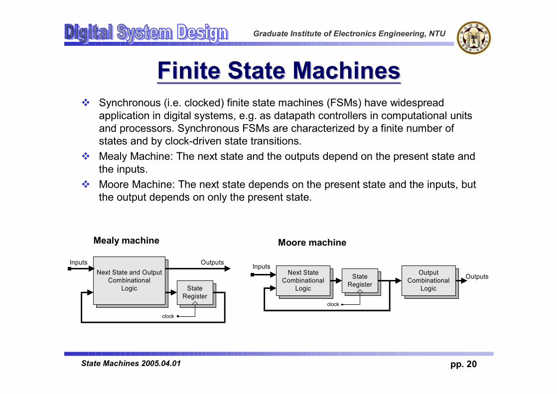
Finite State MachinesFinite State Machinesv Synchronous (i.e. clocked) finite state machines (FSMs) have widespread
application in digital systems, e.g. as datapath controllers in computational units and processors. Synchronous FSMs are characterized by a finite number of states and by clock-driven state transitions.
v Mealy Machine: The next state and the outputs depend on the present state and the inputs.
v Moore Machine: The next state depends on the present state and the inputs, but the output depends on only the present state.
Next StateCombinational
Logic
InputsState
RegisterOutputsOutput
CombinationalLogic
clock
Moore machine
Next State and OutputCombinational
Logic
Inputs
StateRegister
Outputs
clock
Mealy machine

Graduate Institute of Electronics Engineering, NTU
pp. 21State Machines 2005.04.01
What is FSMWhat is FSMv A model of computation consisting ofv a set of states, (limited number)v a start state,v input symbols,v a transition function that maps input symbols and current
states to a next state.

Graduate Institute of Electronics Engineering, NTU
pp. 22State Machines 2005.04.01
Elements of FSMElements of FSMvMemory Elements (ME)vMemorize Current States (CS)v Usually consist of FF or latchv N-bit FF have 2n possible states
v Next-state Logic (NL)v Combinational Logicv Produce next stateØ Based on current state (CS) and input (X)
v Output Logic (OL)v Combinational Logicv Produce outputs (Z)Ø Based on current state, orØ Based on current state and input

Graduate Institute of Electronics Engineering, NTU
pp. 23State Machines 2005.04.01
Mealy MachineMealy Machinev Output is function of bothv Input and current state

Graduate Institute of Electronics Engineering, NTU
pp. 24State Machines 2005.04.01
Moore MachineMoore Machinev Output is function of CS onlyv Not function of inputs

Graduate Institute of Electronics Engineering, NTU
pp. 25State Machines 2005.04.01
Mealy Finite State Machine Mealy Finite State Machine
A serially-transmitted BCD (8421 code) word is to be converted into an Excess-3 code. An Excess-3 code word is obtained by adding 3 to the decimal value and taking the binary equivalent. Excess-3 code is self-complementing [Wakerly, p. 80], i.e. the 9's complement of a code word is obtained by complementing the bits of the word.
Decimal 8-4-2-1 Excess-3Digit Code Code
(BCD)
0 0000 00111 0001 01002 0010 01013 0011 01104 0100 01115 0101 10006 0110 10017 0111 10108 1000 10119 1001 1100
Excess-3Code
Converter
clk
Bout = 8Excess-3
1 0 0 0+
1 1 10
Bin = 8 bcd
Bout
0 0 1 11 0 1 1
LSBMSB
0 0 0 1t
LSB MSB
t
MSBBin

Graduate Institute of Electronics Engineering, NTU
pp. 26State Machines 2005.04.01
Mealy Finite State Machine Mealy Finite State Machine
v The vertices of the state transition graph of a Mealy machine are labeled with the states. v The branches are labeled with (1) the input that causes a transition to the indicated next
state, and (2) with the output that is asserted in the present state for that input. v The state transition is synchronized to a clock. v The state table summarizes the machine's behavior in tabular format.
The serial code converter is described by the state transition graph of a Mealy FSM.
S_5
S_0
input / output
1/00/1
0/1
0/0, 1/1
1/0
0/11/0
0/10/0, 1/1
0/0, 1/1
S_1 S_2
S_4S_3
S_6
State Transition Graph
statenext state/output
input0 1
S_0 S_1 / 1 S_2 / 0S_1 S_3 / 1 S_4 / 0S_2 S_4 / 0 S_4 / 1S_3 S_5 / 0 S_5 / 1S_4 S_5 / 1 S_6 / 0S_5 S_0 / 0 S_0 / 1S_6 S_0 / 1 - / -
Next State/OutputTable

Graduate Institute of Electronics Engineering, NTU
pp. 27State Machines 2005.04.01
Design of a Mealy Finite State MachineDesign of a Mealy Finite State Machine
To design a D-type flip-flop realization of a FSM having the behavior described by a state transition graph, (1) select a state code, (2) encode the state table, (3) develop Boolean equations describing the input of a D-type flip-flop, and (4) using K-maps, optimize the Boolean equations.
statenext state/output
input0 1
S_0 S_1 / 1 S_2 / 0S_1 S_3 / 1 S_4 / 0S_2 S_4 / 0 S_4 / 1S_3 S_5 / 0 S_5 / 1S_4 S_5 / 1 S_6 / 0S_5 S_0 / 0 S_0 / 1S_6 S_0 / 1 - / -
Next State/Output Table
1
0 1
q0
S_0
S_6 S_4
S_2
S_5 S_31
1 0
0 1
0 0
q2 q1
S_1
State Assigment q2 q1 q0 q2+ q1
+ q0+
input0 1
state next state output
input0 1
S_0 000 001 101 1 0
001 111 011 1 0
101 011 011 0 1
111 110 110 0 1
011 110 010 1 0
110 000 000 0 1
010 000 - 1 -
100 - - - -
S_1
S_2
S_3
S_4
S_5
S_6
Encoded Next state/ Output Table

Graduate Institute of Electronics Engineering, NTU
pp. 28State Machines 2005.04.01
Design of a Mealy Finite State MachineDesign of a Mealy Finite State Machine
q2 q1
00
10
11
01
00 01 11 10
1q2 q1
q0 Bin
1 1 1
0 0 0
0 0 0 0
x x 1 1
0
q0+ = q1'
S_0 S_0 S_1 S_1
S_6 S_6 S_4 S_4
S_5 S_5 S_3 S_3
S_2 S_2
00
10
11
01
00 01 11 10
0q2 q1
q0 Bin
0 1 1
0 1 1
0 0 1 1
x x 1 1
0
q1+ = q0
S_0 S_0 S_1 S_1
S_6 S_6 S_4 S_4
S_5 S_5 S_3 S_3
S_2 S_2
00
10
11
01
00 01 11 10
1
q0 Bin
0 0 1
1 0 1
0 1 1 0
x x 1 0
0
Bout = q2'Bin' + q2Bin
S_0 S_0 S_1 S_1
S_6 S_6 S_4 S_4
S_5 S_5 S_3 S_3
S_2 S_2
00
10
11
01
00 01 11 10
0q2 q1
q0 Bin
1 0 1
0 0 1
0 0 1 1
x x 0 0
0S_0 S_0
q2+ = q1'q0'Bin + q2'q0Bin' + q2q1q0
S_1 S_1
S_6 S_6 S_4 S_4
S_5 S_5 S_3 S_3
S_2 S_2
q2+ = q1'q0'Bin + q2'q0Bin' + q2q1q0
q2+ = q1'q0'Bin + q2'q0Bin' + q2q1q0
q2+ = q1'q0'Bin q2'q0Bin' q2q1q0
q2+ = q1'q0'Bin q2'q0Bin' q2q1q0
Note: We will optimize the equations individually. In general - this does not necessarily produce the optimal (area, speed) realization of the logic. We'll address this when we consider synthesis.

Graduate Institute of Electronics Engineering, NTU
pp. 29State Machines 2005.04.01
Design of a Mealy Finite State MachineDesign of a Mealy Finite State Machine
Realization of the sequential BCD-to-Excess-3 code converter (Mealy machine):
q1'q0'
q2'q0
q0q1q2
D
Q
Q
D
Q
Q
D
Q
Q
Bout
Bin
clk
q2'
q2
q1'
q1
q0
q0'
q1'
q0
Bin
Bin'Bin'
q2+ = q1'q0'Bin + q2'q0Bin' + q2q1q0
q2+ = q1'q0'Bin + q2'q0Bin' + q2q1q0
q2+ = q1'q0'Bin q2'q0Bin' q2q1q0
q2+ = q1'q0'Bin q2'q0Bin' q2q1q0

Graduate Institute of Electronics Engineering, NTU
pp. 30State Machines 2005.04.01
Design of a Mealy Finite State MachineDesign of a Mealy Finite State Machine
0 10 01 11 0
B_inB_out
Simulation results for Mealy machine:

Graduate Institute of Electronics Engineering, NTU
pp. 31State Machines 2005.04.01
ExamplesExamplesv Design of A Serial Line Code Converterv Serial Line Codes [Wakerly] are used for serial data
transmission or storage.ØNRZ Code ØNRZI CodeØRZ CodeØManchester Code
SerialBit Value 0 1 1 1 0 0 1 0
NRZMealy
RZ
Manchester
time
clock_1
clock_2
NRZMoore
NRZIMealy
NRZIMoore
B_in

Graduate Institute of Electronics Engineering, NTU
pp. 32State Machines 2005.04.01
Serial Line Code Converter Serial Line Code Converter Mealy FSM Mealy FSM
Objective: Design a Mealy-type FSM that converts a data stream in NRZ format to a data stream in Manchester code format.
NRZ-to-Manchester
CodeConverter
DataManchesterDataNRZ
S_0 S_1S_2
0 / 0
0 / 11 / 0
1 / 1
SerialBit Value 0 1 1 1 0 0 1 0
NRZMealy
time
B_in
Manchester
clock_1
clock_2

Graduate Institute of Electronics Engineering, NTU
pp. 33State Machines 2005.04.01
Serial Line Code Converter Serial Line Code Converter Mealy FSMMealy FSM
S_0 S_1S_2
0 / 0
0 / 11 / 0
1 / 1
State Transition Graph
statenext state/output
input0 1
S_0 S_1 / 0 S_2 / 1S_1 S_0 / 1 -S_2 - S_0 / 0
0 1
q0
S_0
S_21
0
q1
S_1
q1 q0 q1+ q0
+
input0 1
state next state output
input0 1
S_0 00 01 10 0 1
01 00 - 1 -
10 - 00 - 0
S_1
S_2
State Table:
State Code:
Encoded State Table:

Graduate Institute of Electronics Engineering, NTU
pp. 34State Machines 2005.04.01
Serial Line Code Converter Serial Line Code Converter Mealy FSMMealy FSM
q1 q0 q1+ q0
+
input0 1
state next state output
input0 1
S_0 00 01 10 0 1
01 00 - 1 -
10 - 00 - 0
S_1
S_2
10
01
00
0 1
0
Bin
q1 q0
1
1 1S_0 S_0
S_1
-
S_2- 0
S_1
-
S_2
Bout = q1' (q0 + Bin )
11
10
01
00
0 11
Bin
q1 q0
0
0 0S_0 S_0
S_1
-
S_20 0
S_1
-
S_2
q0+ = q1'q0'Bin'
1111
10
01
000 10
Bin
q1 q0
1
0 0S_0 S_0
S_1
0S_2
- -S_1
0S_2
q1+ = q1'q0'Bin
q0'
B_in'
D
Q
Q
D
Q
Q
Bout
clkq1'
q1
q0
q0'
q1'
q0'Bin
q1'
Bin
Encoded State Table:
Karnaugh Maps:

Graduate Institute of Electronics Engineering, NTU
pp. 35State Machines 2005.04.01
Serial Line Code Converter Serial Line Code Converter Mealy FSMMealy FSM
Input and output bit times coincide
Note: The Mealy machine's output is subject to glitches in the input bit stream.

Graduate Institute of Electronics Engineering, NTU
pp. 36State Machines 2005.04.01
Serial Line Code Converter Serial Line Code Converter Moore FSM Moore FSM
Objective: Design a Moore-type FSM that converts a data stream in NRZ format to a data stream in Manchester code format.
NRZ-to-Manchester
CodeConverter
DataManchesterDataNRZ
SerialBit Value 0 1 1 1 0 0 1 0
NRZMealy
time
B_in
Manchester
clock_1
clock_2
0S_00
S_10
S_31
S_211
0
0
011

Graduate Institute of Electronics Engineering, NTU
pp. 37State Machines 2005.04.01
Serial Line Code Converter Serial Line Code Converter Moore FSMMoore FSM
State Transition Graph
State Table:
State Code:
Encoded State Table:
0S_00
S_10
S_31
S_211
0
0
011
statenext state/output
input0 1
S_0 S_1 / 0 S_3 / 1S_1 S_2 / 1 -S_3 - S_0 / 1S_2 S_1 / 0 S_3 / 0
0 1
q0
S_0
S_2 S_31
0
q1
S_1
q1 q0 q1+ q0
+
input0 1
state next state output
S_0 00 01 11 0
01 10 - 0
11 - 00 1
S_1
S_3
10 01 11 1S_2

Graduate Institute of Electronics Engineering, NTU
pp. 38State Machines 2005.04.01
Serial Line Code ConverterSerial Line Code ConverterMoore FSMMoore FSM
Karnaugh Maps:
Encoded State Table:
q1 q0 q1+ q0
+
input0 1
state next state output
S_0 00 01 11 0
01 10 - 0
11 - 00 1
S_1
S_3
10 01 11 1S_2
q0
D
Q
Q
D
Q
QBout
clk
q0'
q0
q1
q1'
q1'
q0'
Bin
1
0
0 1
0
q0q1
0
1 1S_0 S_0
S_1 S_1
B_out = q1
10
01
00
0 11
Binq1 q0
1
0 -S_0 S_0
S_1
0
S_21 1
S_1
-
S_2
q0+ = q0'
11S_3 S_3
11
10
01
00
0 1
0
Binq1 q0
1
1 -S_0 S_0
S_1
1S_2
- 0S_1
0S_2
q1+ = q1'q0 + q0'Bin
S_3 S_3

Graduate Institute of Electronics Engineering, NTU
pp. 39State Machines 2005.04.01
Serial Line Code Converter Serial Line Code Converter Moore FSMMoore FSM
NRZ bit time
Manchester bit time
Note: The Manchester encoder must run at twice the frequency of the incoming data.
The output bit stream lags the input bit stream by one-half the input cycle time.

ACCESS IC LAB
Graduate Institute of Electronics Engineering, NTU
Building Behavioral ModelsBuilding Behavioral Models

Graduate Institute of Electronics Engineering, NTU
pp. 41State Machines 2005.04.01
Modeling Modeling FSMsFSMs BehaviorallyBehaviorallyvThere are many ways to do it:
vDefine the next-state logic combinationallyand define the state-holding latches explicitly
vDefine the behavior in a single always @(posedge clk) block
vVariations on these themes

Graduate Institute of Electronics Engineering, NTU
pp. 42State Machines 2005.04.01
FSM with Combinational LogicFSM with Combinational Logicmodule FSM(o, a, b, reset);output o;reg o;input a, b, reset;reg [1:0] state, nextState;
always @(a or b or state)case (state)
2’b00: beginnextState = a ? 2’b00 : 2’b01;o = a & b;
end2’b01: begin nextState = 2’b10; o = 0; end
endcase
Combinational block must be sensitive to any change on any of its inputs(Implies state-holding elements otherwise)
Output o is declared a regbecause it is assigned procedurally, not because it holds state
Graduate Institute of Electronics Engineering, NTU
pp. 43State Machines 2005.04.01
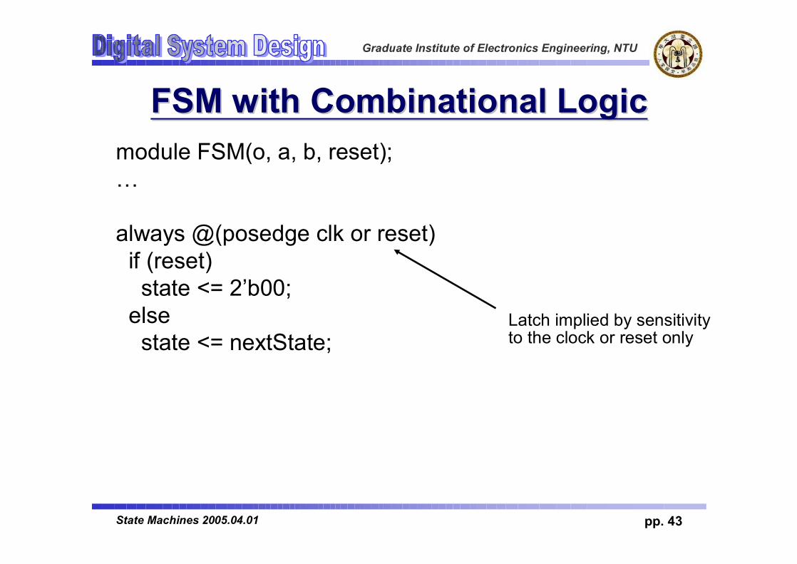
FSM with Combinational LogicFSM with Combinational Logicmodule FSM(o, a, b, reset);…
always @(posedge clk or reset)if (reset)state <= 2’b00;
elsestate <= nextState;
Latch implied by sensitivity to the clock or reset only

Graduate Institute of Electronics Engineering, NTU
pp. 44State Machines 2005.04.01
FSM from Combinational LogicFSM from Combinational Logicalways @(a or b or state)case (state)
2’b00: beginnextState = a ? 2’b00 : 2’b01;o = a & b;
end2’b01: begin nextState = 2’b10; o = 0; end
endcase
always @(posedge clk or reset)if (reset)state <= 2’b00;
elsestate <= nextState;
This is a Mealy machine because the output is directly affected by any change on the input

Graduate Institute of Electronics Engineering, NTU
pp. 45State Machines 2005.04.01
FSM from a Single Always BlockFSM from a Single Always Blockmodule FSM(o, a, b);output o; reg o;input a, b;reg [1:0] state;
always @(posedge clk or reset)if (reset) state <= 2’b00;else case (state)2’b00: begin
state <= a ? 2’b00 : 2’b01;o <= a & b;
end2’b01: begin state <= 2’b10; o <= 0; end
endcase
Expresses Moore machine behavior:Outputs are latchedInputs only sampled at clock edges
Nonblockingassignments used throughout to ensure coherency.RHS refers to values calculated in previous clock cycle

ACCESS IC LAB
Graduate Institute of Electronics Engineering, NTU
FSM ExampleFSM Example

Graduate Institute of Electronics Engineering, NTU
pp. 47State Machines 2005.04.01
Modeling FSMModeling FSMvNext State (NS)vCurrent State (CS)vOutput Logic (OL)

Graduate Institute of Electronics Engineering, NTU
pp. 48State Machines 2005.04.01
Coding styleCoding stylevCS+OL is bad stylevAdd reset to set initial statevState encoding

Graduate Institute of Electronics Engineering, NTU
pp. 49State Machines 2005.04.01
lowspeed
stopped
mediumspeed
highspeed
brake=1
brake=0accelerator=1
brake=1
brak
e=0
acce
lera
tor=
1
brake=1
brake=1 brake=0accelerator=1
brake=0accelerator=1
brake
accelerator
clock
speed
Behavioral Models of Finite State MachinesBehavioral Models of Finite State Machinesexample1example1

Graduate Institute of Electronics Engineering, NTU
pp. 50State Machines 2005.04.01
FSM Example1FSM Example1
`timescale 1ns/10psmodule fsm(clk,acc,brake,speed);
input clk,acc,brake; output [1:0] speed; reg [1:0] state,next_state;
parameter stopped =2'b00; parameter s_low =2'b01; parameter s_medium=2'b10; parameter s_high =2'b11;
assign speed=state;
always @(posedge clk) state <= next_state;
always @(state or acc or brake) if (brake) case (state) stopped: next_state<=stopped; s_low: next_state<=stopped; s_high: next_state<=s_medium; s_medium:next_state<=s_low; default: next_state<=stopped; endcase else if(acc) case(state) stopped: next_state<=s_low; s_low: next_state<=s_medium; s_medium:next_state<=s_high; s_high: next_state<=s_high; default: next_state<=stopped; endcase else next_state<=state;endmodule

Graduate Institute of Electronics Engineering, NTU
pp. 51State Machines 2005.04.01
FSM Example1FSM Example1v(CS, OL, NS) Use 2 DFFs

Graduate Institute of Electronics Engineering, NTU
pp. 52State Machines 2005.04.01
FSM Example2 (CS,OL+NS)FSM Example2 (CS,OL+NS)//assign speed=state;always @(posedge clk or posedge
rst)beginif (rst)
state<=0;else beginstate <= next_state;case(state)
stopped: speed<=stopped;s_low : speed<=s_low;s_medium: speed<=s_medium;s_high : speed<=s_high;
endcaseend
end
always @(state or acc or brake)if (brake)
case (state)stopped: next_state<=stopped;s_low: next_state<=stopped;s_high: next_state<=s_medium;s_medium:next_state<=s_low;default: next_state<=stopped;
endcaseelse if(acc)
case(state)stopped: next_state<=s_low;s_low: next_state<=s_medium;s_medium:next_state<=s_high;s_high: next_state<=s_high;default: next_state<=stopped;
endcaseelse
next_state<=state;endmodule

Graduate Institute of Electronics Engineering, NTU
pp. 53State Machines 2005.04.01
FSM Example2 (CS,OL+NS)FSM Example2 (CS,OL+NS)Use Use 44 DFFsDFFs

Graduate Institute of Electronics Engineering, NTU
pp. 54State Machines 2005.04.01
State encodingState encoding

Graduate Institute of Electronics Engineering, NTU
pp. 55State Machines 2005.04.01
Homework #4Homework #4vModeling cross traffic signal controller