Embed Size (px)
Citation preview
||Autonomous Systems Lab
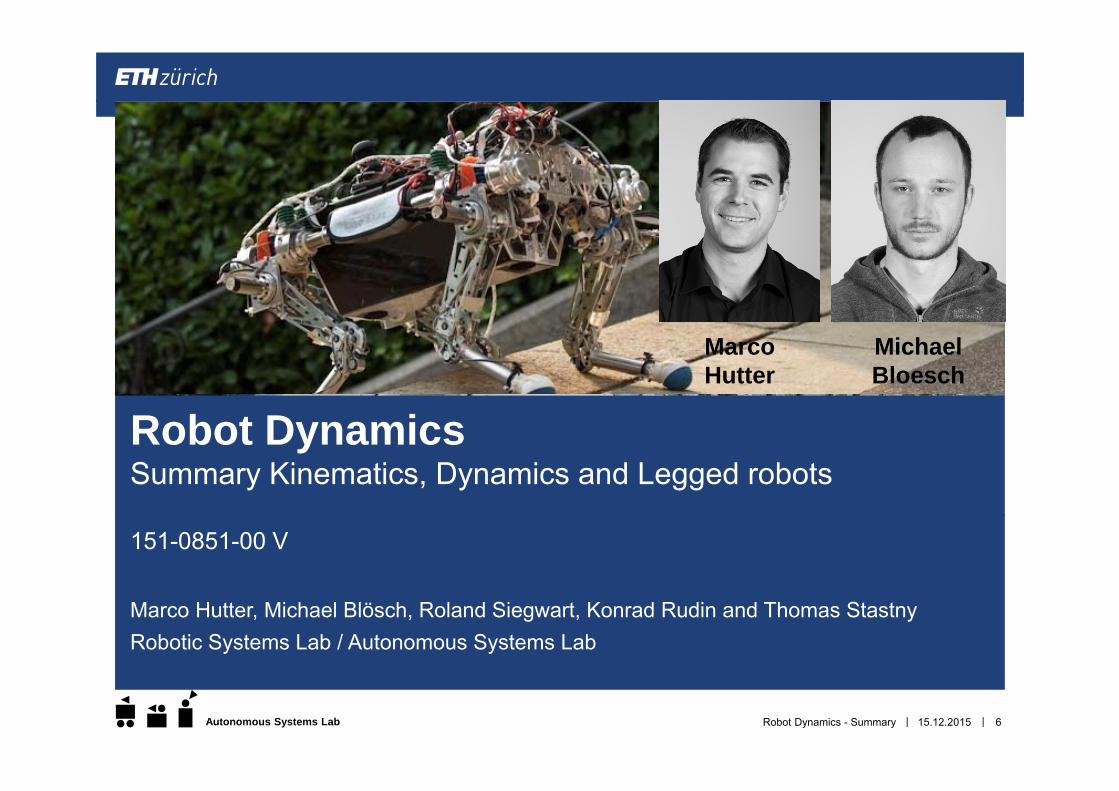
151-0851-00 V
Marco Hutter, Michael Blösch, Roland Siegwart, Konrad Rudin and Thomas Stastny
15.12.2015Robot Dynamics - Summary 1
Robot DynamicsSummary
||Autonomous Systems Lab
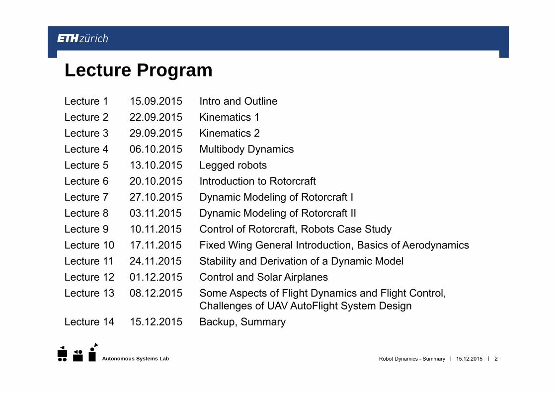
Lecture 1 15.09.2015 Intro and OutlineLecture 2 22.09.2015 Kinematics 1 Lecture 3 29.09.2015 Kinematics 2 Lecture 4 06.10.2015 Multibody Dynamics Lecture 5 13.10.2015 Legged robots Lecture 6 20.10.2015 Introduction to Rotorcraft Lecture 7 27.10.2015 Dynamic Modeling of Rotorcraft I Lecture 8 03.11.2015 Dynamic Modeling of Rotorcraft II Lecture 9 10.11.2015 Control of Rotorcraft, Robots Case Study Lecture 10 17.11.2015 Fixed Wing General Introduction, Basics of Aerodynamics Lecture 11 24.11.2015 Stability and Derivation of a Dynamic Model Lecture 12 01.12.2015 Control and Solar Airplanes Lecture 13 08.12.2015 Some Aspects of Flight Dynamics and Flight Control,
Challenges of UAV AutoFlight System Design Lecture 14 15.12.2015 Backup, Summary
15.12.2015Robot Dynamics - Summary 2
Lecture Program
||Autonomous Systems Lab
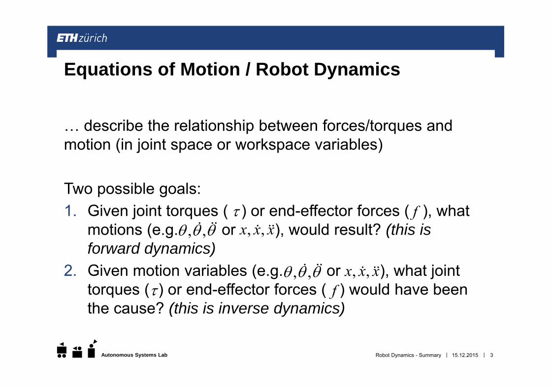
… describe the relationship between forces/torques and motion (in joint space or workspace variables)
Two possible goals:1. Given joint torques ( ) or end-effector forces ( ), what
motions (e.g. or ), would result? (this is forward dynamics)
2. Given motion variables (e.g. or ), what joint torques ( ) or end-effector forces ( ) would have been the cause? (this is inverse dynamics)
15.12.2015Robot Dynamics - Summary 3
Equations of Motion / Robot Dynamics
f, , , ,x x x
, , , ,x x x f
||Autonomous Systems Lab 15.12.2015Robot Dynamics - Summary 4
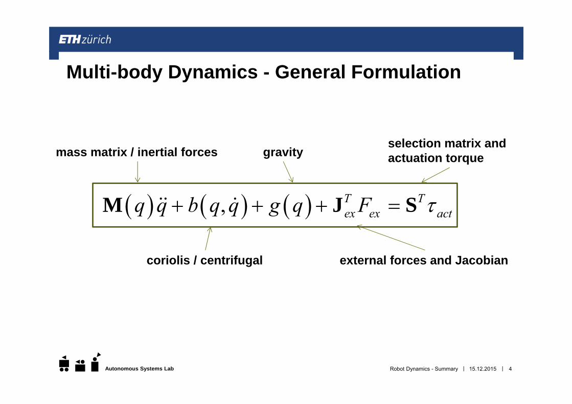
Multi-body Dynamics - General Formulation
, T Tex ex actq q b q q g q F M J S
mass matrix / inertial forces
coriolis / centrifugal
gravity
external forces and Jacobian
selection matrix and actuation torque
||Autonomous Systems Lab
The main elements (general for all mechanical systems) Generalized coordinates Coordinate transformation Kinematics and Jacobian Multi-body dynamics
System dependent Actuator External forces (interaction, aerodynamics, …) Simplifications
15.12.2015Robot Dynamics - Summary 5
Equation of Motion / Robot Dynamics
||Autonomous Systems Lab
151-0851-00 V
Marco Hutter, Michael Blösch, Roland Siegwart, Konrad Rudin and Thomas StastnyRobotic Systems Lab / Autonomous Systems Lab
15.12.2015Robot Dynamics - Summary 6
Robot DynamicsSummary Kinematics, Dynamics and Legged robots
MarcoHutter
MichaelBloesch
||Autonomous Systems Lab
Generalized coordinates, rotations, and transformations Different representations and descriptions of joint and task space Mapping from joint space to task space Exam: provide us with the homogeneous transformation matrix between
two points of a robot arm Differential kinematics, Jacobians Relation between joint and task space motion Exam: provide us with the end-effector Jacobian for a given robot arm
Inverse (differential) kinematics Given a task space motion/configuration, what is the joint
motion/configuration Singularity and redundancy Exam: show us how to determine the generalized coordinates for a given
end-effector position
15.12.2015Robot Dynamics - Summary 7
Kinematics | Summary and possible exam questions
||Autonomous Systems Lab
Equation of Motion (EoM) Impulse and angular momentum (for single bodies and multi-body-
systems) Concept of Newton-Euler (NE), projected NE, and Lagrange II Exam: given a robot system, outline how to determine the EoM Exam: given an external force, how does it influence the EoM
Inverse dynamics Inverse joint and task space dynamics as model-based control concept Ex: given the EoM and a desired contact force, determine the joint torque
Floating base systems (Legged robots) Non-actuated based and contact constraints Null-space motion and multi-task execution Ex: given a robot in contact with the environment, determine how it can
move
15.12.2015Robot Dynamics - Summary 8
Dynamics | Summary and possible exam questions
||Autonomous Systems Lab
151-0851-00 V
Marco Hutter, Michael Blösch, Roland Siegwart, Konrad Rudin and Thomas StastnyAutonomous Systems Lab
15.12.2015Robot Dynamics - Summary 9
Robot DynamicsSummary Rotorcrafts
KonradRudin
RolandSiegwart
||Autonomous Systems Lab
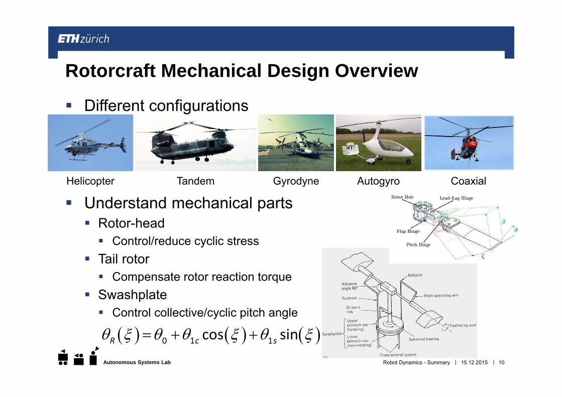
Different configurations
Understand mechanical parts Rotor-head Control/reduce cyclic stress
Tail rotor Compensate rotor reaction torque
Swashplate Control collective/cyclic pitch angle
Robot Dynamics - Summary
Rotorcraft Mechanical Design Overview
Helicopter Gyrodyne Autogyro CoaxialTandem
0 1 1cos sinR c s
15.12.2015 10
||Autonomous Systems Lab
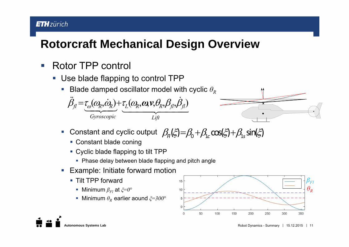
Rotor TPP control Use blade flapping to control TPP Blade damped oscillator model with cyclic θR
Constant and cyclic output Constant blade coning Cyclic blade flapping to tilt TPP Phase delay between blade flapping and pitch angle
Example: Initiate forward motion Tilt TPP forward Minimum βFl at ξ=0° Minimum θR earlier aound ξ=300°
15.12.2015Robot Dynamics - Summary 11
Rotorcraft Mechanical Design Overview
Lift
flflRRL
Gyroscopic
RRfl ),,,,,(),( vω
0 1 1( ) cos( ) sin( )Fl c s
βFlθR
||Autonomous Systems Lab
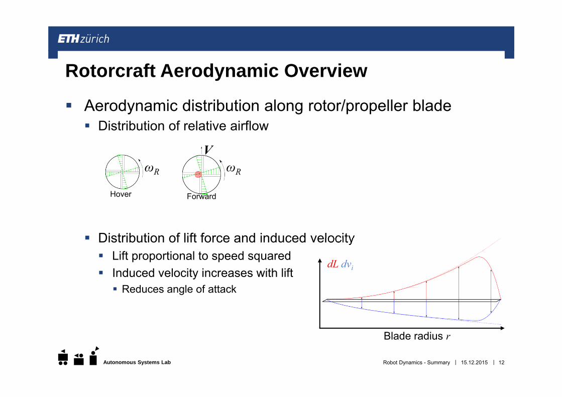
Aerodynamic distribution along rotor/propeller blade Distribution of relative airflow
Distribution of lift force and induced velocity Lift proportional to speed squared Induced velocity increases with lift Reduces angle of attack
Robot Dynamics - Summary
Rotorcraft Aerodynamic Overview
ωR ωR
V
Hover Forward
Blade radius r
dL dvi
15.12.2015 12
||Autonomous Systems Lab
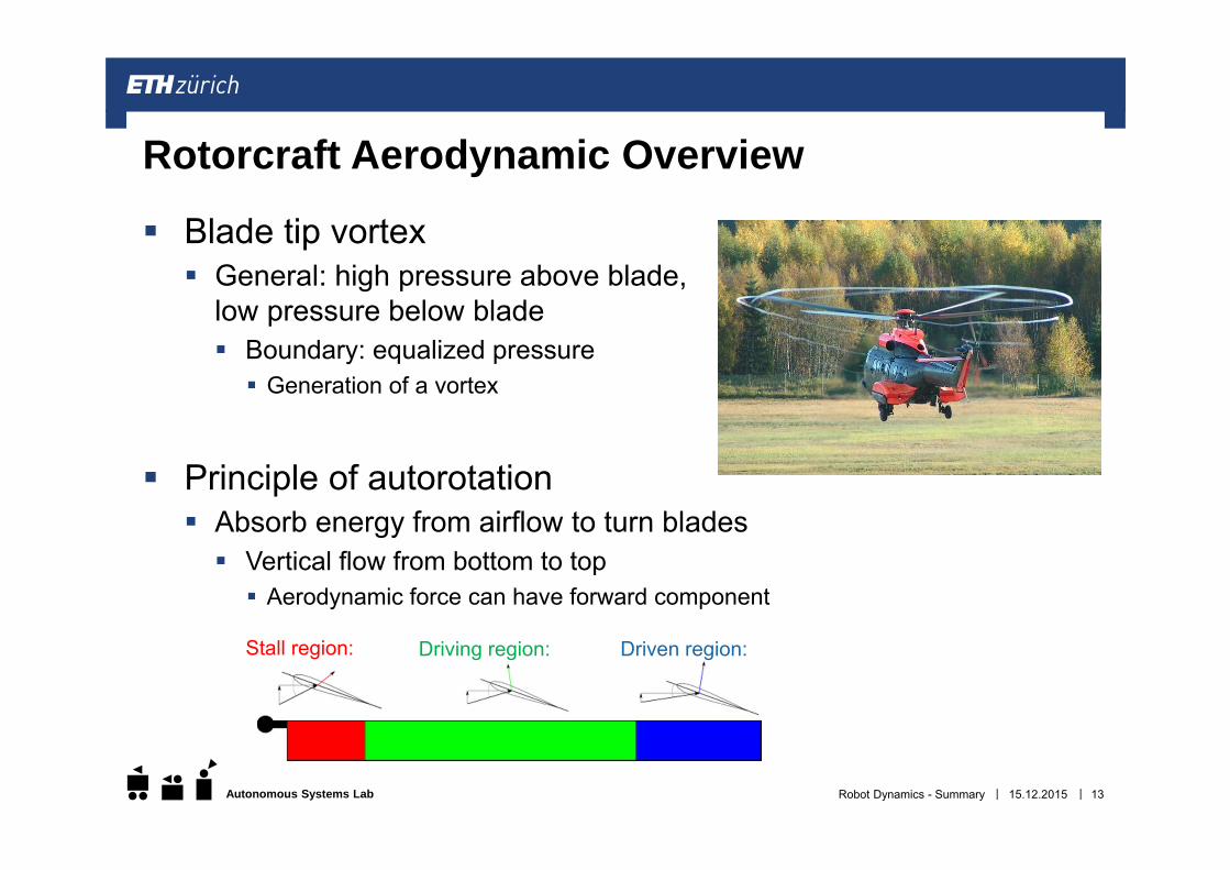
Blade tip vortex General: high pressure above blade,
low pressure below blade Boundary: equalized pressure Generation of a vortex
Principle of autorotation Absorb energy from airflow to turn blades Vertical flow from bottom to top Aerodynamic force can have forward component
15.12.2015Robot Dynamics - Summary 13
Rotorcraft Aerodynamic Overview
Driven region:Driving region:Stall region:
||Autonomous Systems Lab
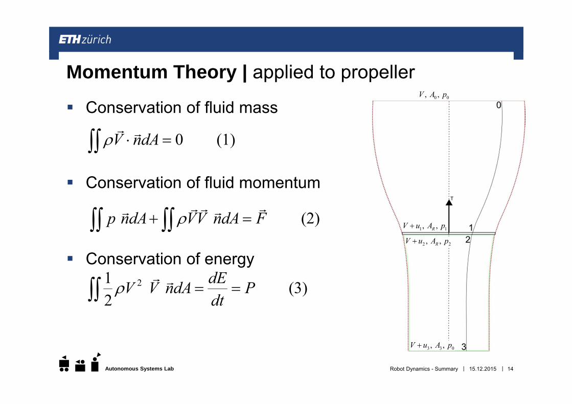
Conservation of fluid mass
Conservation of fluid momentum
Conservation of energy
15.12.2015Robot Dynamics - Summary 14
Momentum Theory | applied to propeller
0 (1)V ndA
(2)p ndA VV ndA F
21 (3)2
dEV V ndA Pdt
0 0, , V A p
1 1, , RV u A p
2 2, , RV u A p
3 3 0, , V u A p
||Autonomous Systems Lab 15.12.2015Robot Dynamics - Summary 15
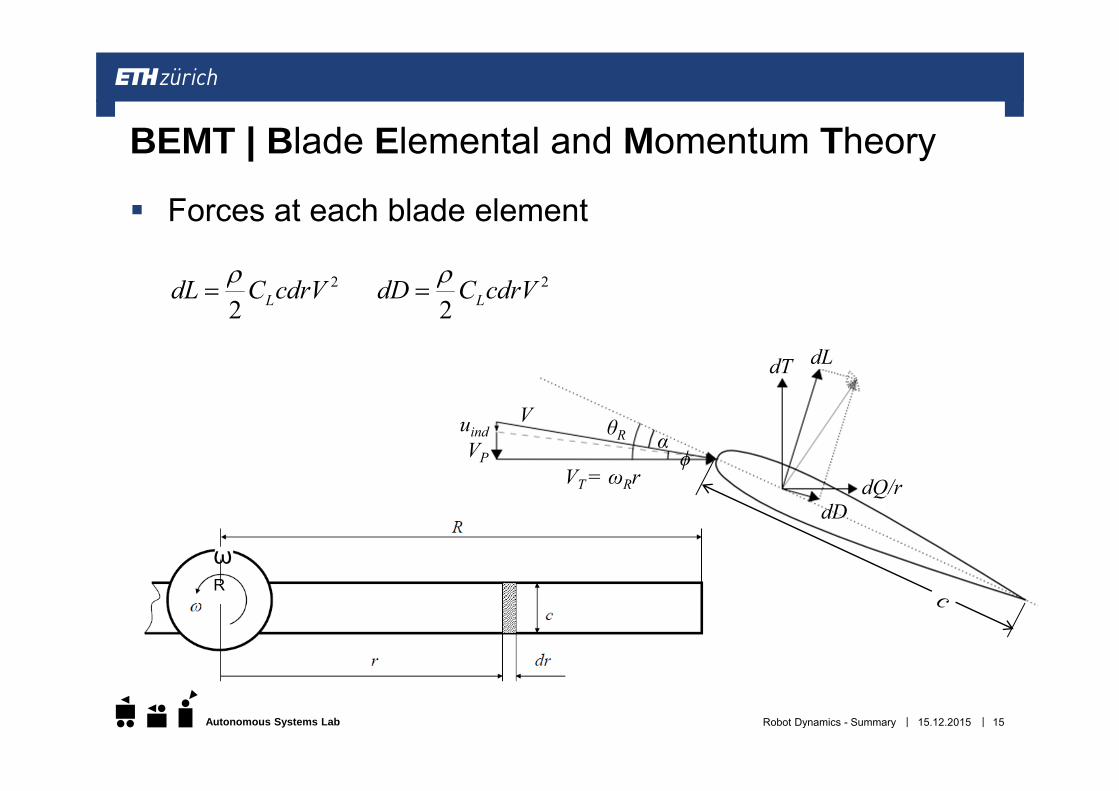
BEMT | Blade Elemental and Momentum Theory
Forces at each blade element
dT dL
dDdQ/r
V
VT = ωRrVP
uind θR αϕ
ωR
2
2 LdL C cdrV 2
2 LdD C cdrV
||Autonomous Systems Lab 15.12.2015Robot Dynamics - Summary 16
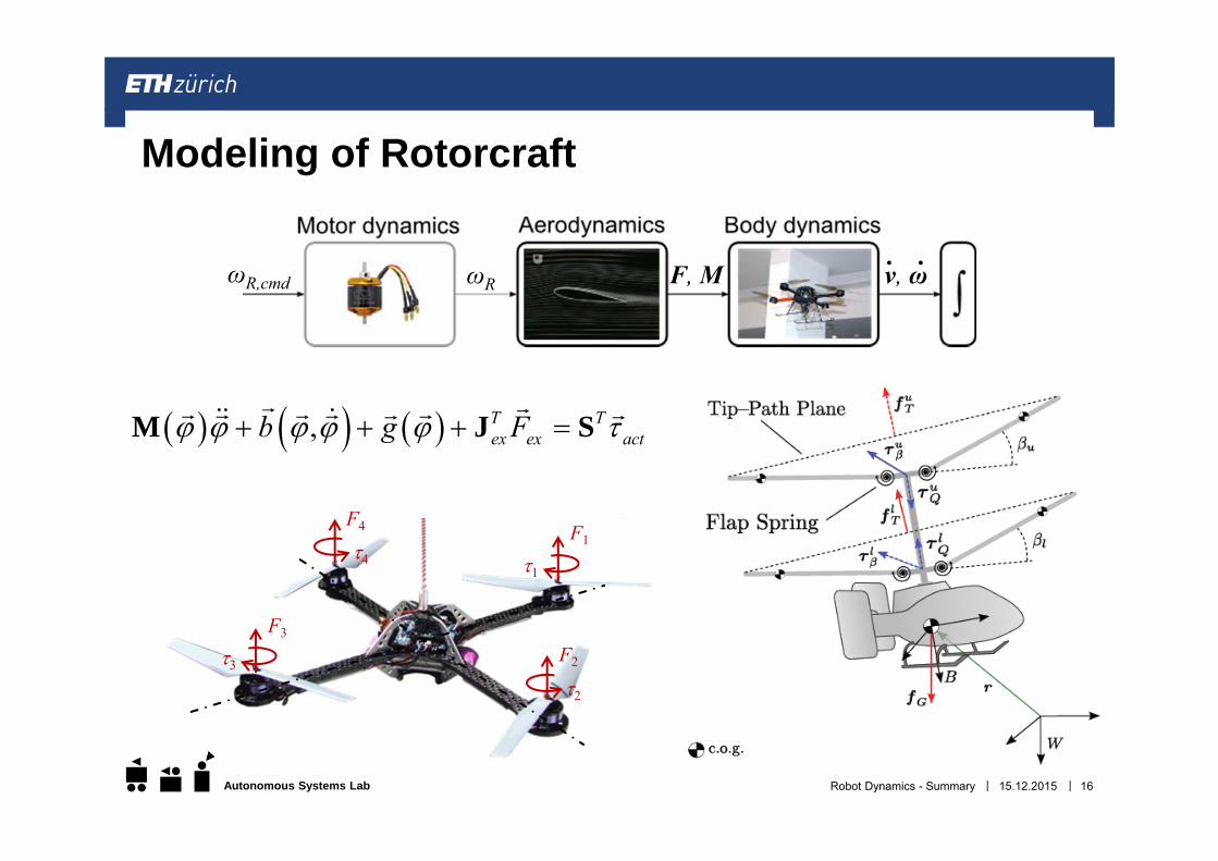
Modeling of Rotorcraft
ωR,cmd ωR F, M v, ω. .
, T Tex ex actb g F M J S
F1
1
F4
4
F3
3 F2
2
||Autonomous Systems Lab
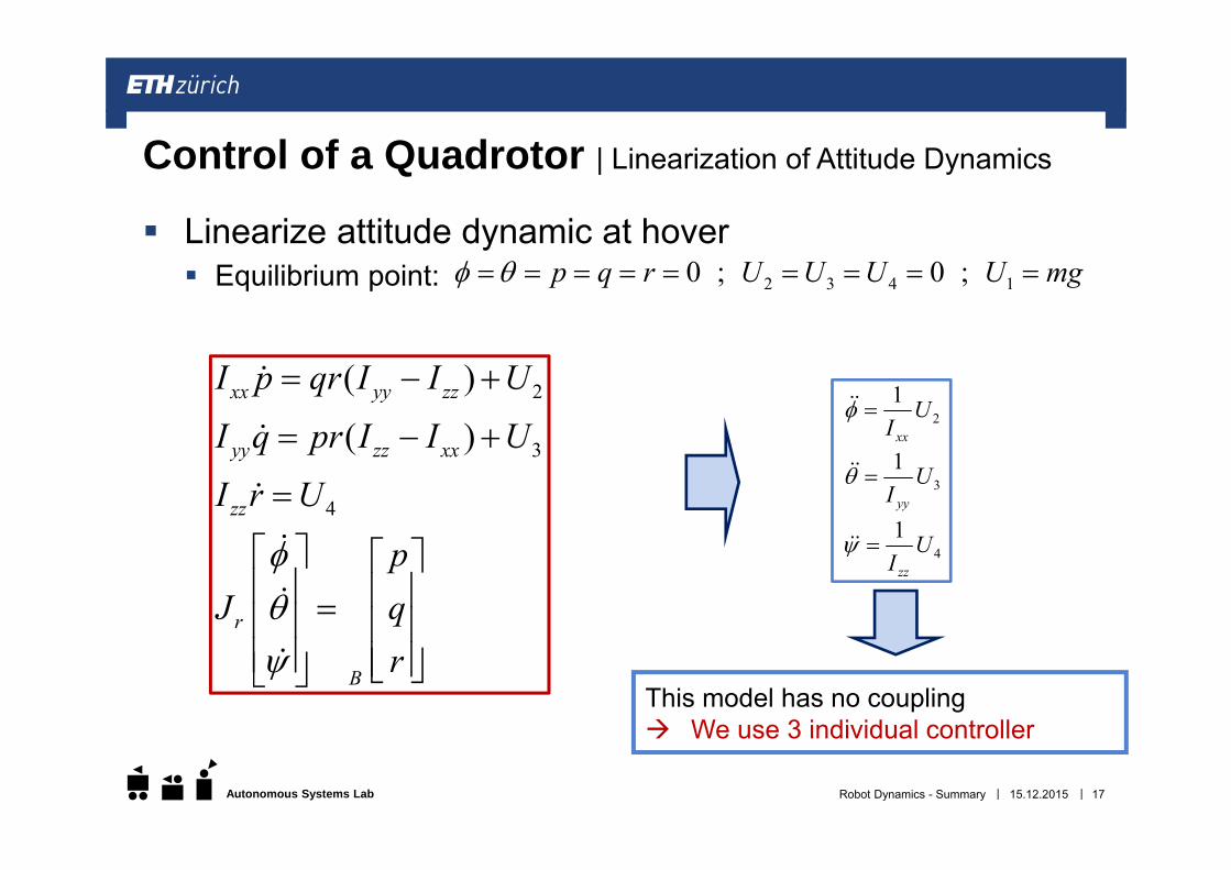
Linearize attitude dynamic at hover Equilibrium point:
15.12.2015Robot Dynamics - Summary 17
Control of a Quadrotor | Linearization of Attitude Dynamics
This model has no coupling We use 3 individual controller
2
3
4
( )
( )xx yy zz
yy zz xx
zz
r
B
I p qr I I U
I q pr I I U
I r U
pJ q
r
21 U
I xx
31 U
I yy
41 UIzz
2 3 4 10 ; 0 ; p q r U U U U mg
||Autonomous Systems Lab
151-0851-00 V
Marco Hutter, Michael Blösch, Roland Siegwart, Konrad Rudin and Thomas StastnyAutonomous Systems Lab
15.12.2015Robot Dynamics - Summary 18
Robot DynamicsSummary Fixed Wing UAS
ThomasStastny
||Autonomous Systems Lab
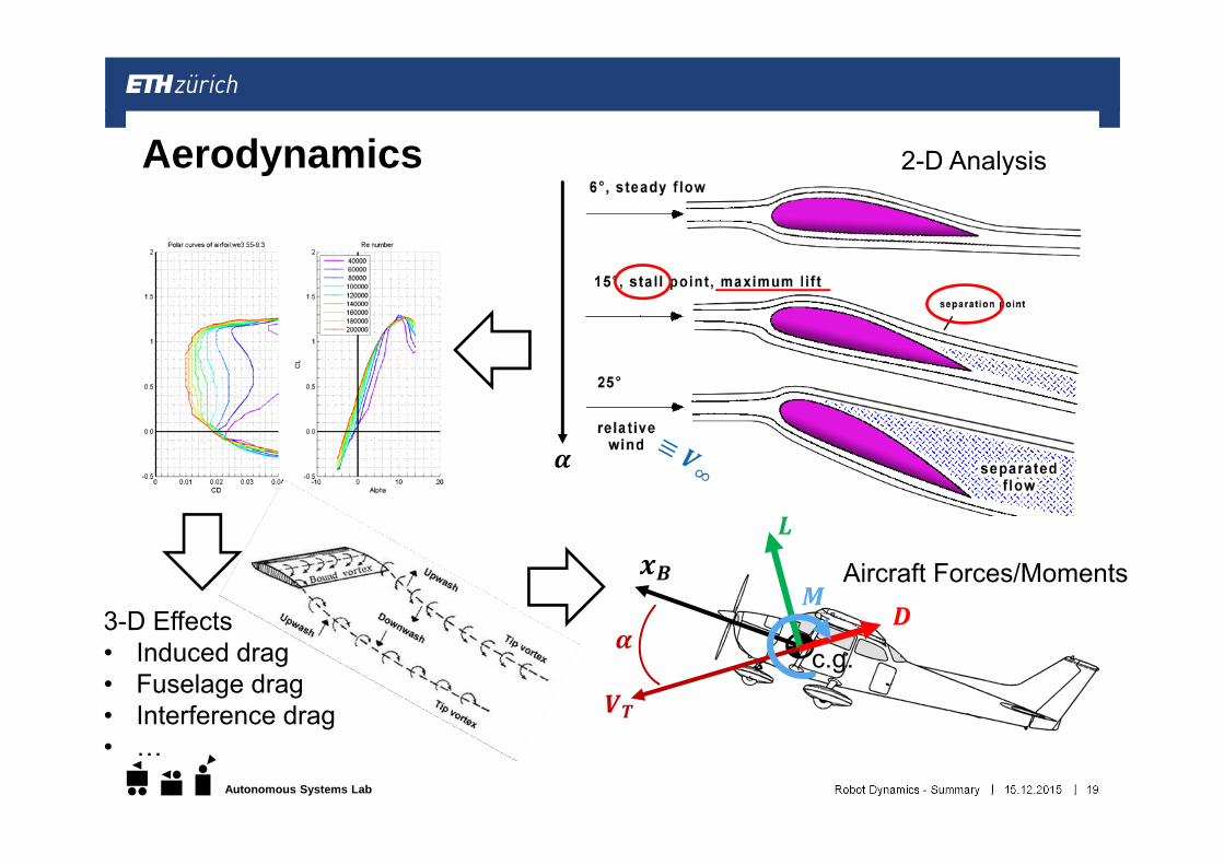
Aerodynamics
15.12.2015Robot Dynamics - Summary 19
c.g.
2-D Analysis
3-D Effects• Induced drag• Fuselage drag• Interference drag• …
Aircraft Forces/Moments
||Autonomous Systems Lab
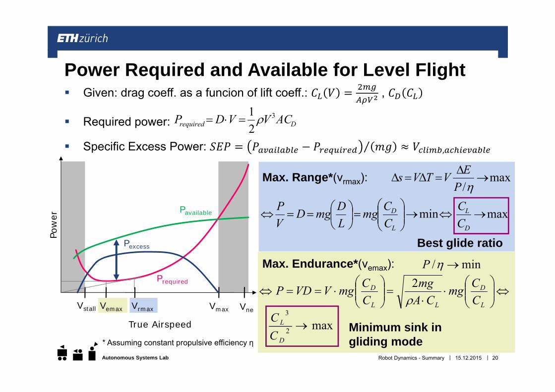
Given: drag coeff. as a funcion of lift coeff.: ,
Required power:
Specific Excess Power: ⁄ ,
15.12.2015Robot Dynamics - Summary 20
Power Required and Available for Level Flight
Drequired ACVVDP 3
21
Pavailable
Prequired
Pexcess
Vstall Vmax Vne
Pow
er
True Airspeed
Vemax Vrmax
min
L
D
CCmg
LDmgD
VP max
D
L
CC
Best glide ratio
max/
PEVTVs
min/ P
max2
3
D
L
CC
L
D
LL
D
CCmg
CAmg
CCmgVVDP
2
Minimum sink in gliding mode
Max. Range*(vrmax):
Max. Endurance*(vemax):
* Assuming constant propulsive efficiency η
||Autonomous Systems Lab
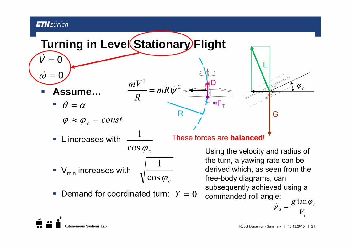
c Assume…
L increases with
Vmin increases with
Demand for coordinated turn:
Turning in Level Stationary Flight00
V
constc
0Y
R
22
mRR
mV
D
≈FT
L
G
ccos1
ccos1
15.12.2015Robot Dynamics - Summary 21
These forces are balanced!
T
cd V
g tan
Using the velocity and radius of the turn, a yawing rate can be derived which, as seen from the free-body diagrams, can subsequently achieved using a commanded roll angle:
||Autonomous Systems Lab
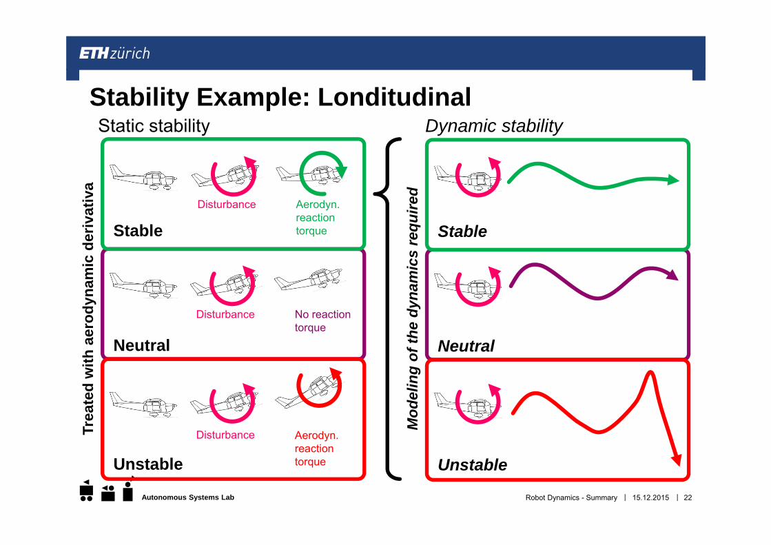
Stability Example: LonditudinalDynamic stabilityStatic stability
Disturbance Aerodyn. reaction torque
Disturbance No reaction torque
Stable
Neutral
Disturbance Aerodyn.reactiontorqueUnstable
Stable
Neutral
Unstable
Trea
ted
with
aero
dyna
mic
deriv
ativ
a
Mod
elin
g of
the
dyna
mic
s re
quire
d
15.12.2015Robot Dynamics - Summary 22
||Autonomous Systems Lab
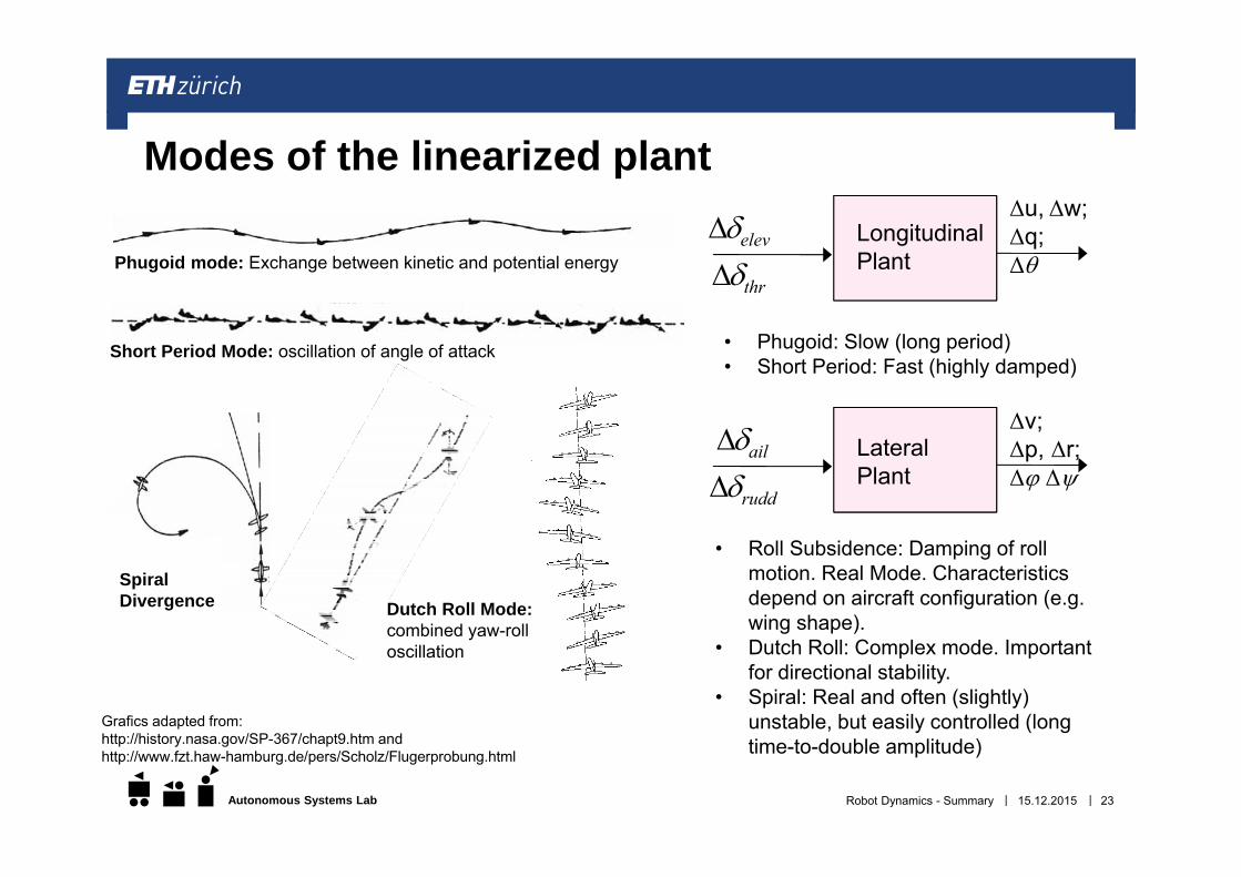
Modes of the linearized plant
Short Period Mode: oscillation of angle of attack
Phugoid mode: Exchange between kinetic and potential energy
Spiral Divergence Dutch Roll Mode:
combined yaw-roll oscillation
Grafics adapted from:http://history.nasa.gov/SP-367/chapt9.htm andhttp://www.fzt.haw-hamburg.de/pers/Scholz/Flugerprobung.html
15.12.2015 23Robot Dynamics - Summary
Δu, Δw; Δq;Δ
thr
elev
Longitudinal
Plant
Δv; Δp, Δr;Δ Δ
rudd
ail
Lateral
Plant
• Phugoid: Slow (long period)• Short Period: Fast (highly damped)
• Roll Subsidence: Damping of roll motion. Real Mode. Characteristics depend on aircraft configuration (e.g. wing shape).
• Dutch Roll: Complex mode. Important for directional stability.
• Spiral: Real and often (slightly) unstable, but easily controlled (long time-to-double amplitude)
||Autonomous Systems Lab
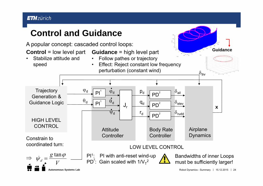
AttitudeController
PI1: PI with anti-reset wind-upPD2: Gain scaled with 1/VT
2
Body Rate Controller
rd
qd
pd PD2
PD2
PD2
Control and Guidance
AirplaneDynamics
rudd
elev
ail
x
PI1
PI1d
d
Constrain tocoordinated turn:
V
gd
tan
d
d
d
Jr
thr
Bandwidths of inner Loops must be sufficiently larger!
TrajectoryGeneration &
Guidance Logic
15.12.2015 24Robot Dynamics - Summary
HIGH LEVEL CONTROL
LOW LEVEL CONTROL
Control = low level part• Stabilize attitude and
speed
Guidance = high level part• Follow pathes or trajectory• Effect: Reject constant low frequency
perturbation (constant wind)
A popular concept: cascaded control loops:Guidance
||Autonomous Systems Lab
Cascaded PID loops Low CPU cost, simple design Only effective within small deviations from the design point
Optimal Control Gains typically must be computed offline Techniques like LQR can achieve better performance as a MIMO controller than
PID, but depends on the selected weighting Robust Control Target and reject certain frequencies within signals More complex to design Without proper loop shaping, often must trade performance for wider reaching
stability Many more! The chosen control techniques determined according to: Computational Power Type of flight (aerobatics - level flight)
Control Concepts
15.12.2015 25Robot Dynamics - Summary
||Autonomous Systems Lab
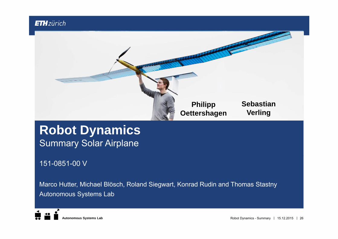
151-0851-00 V
Marco Hutter, Michael Blösch, Roland Siegwart, Konrad Rudin and Thomas StastnyAutonomous Systems Lab
15.12.2015Robot Dynamics - Summary 26
Robot DynamicsSummary Solar Airplane
PhilippOettershagen
Sebastian Verling
||Autonomous Systems Lab 15.12.2015Robot Dynamics - Summary 27
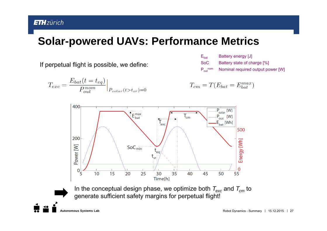
Solar-powered UAVs: Performance Metrics
If perpetual flight is possible, we define:
In the conceptual design phase, we optimize both Texc and Tcm togenerate sufficient safety margins for perpetual flight!
Ebat Battery energy [J]SoC Battery state of charge [%]Pout
nom Nominal required output power [W]
||Autonomous Systems Lab 15.12.2015Robot Dynamics - Summary 28
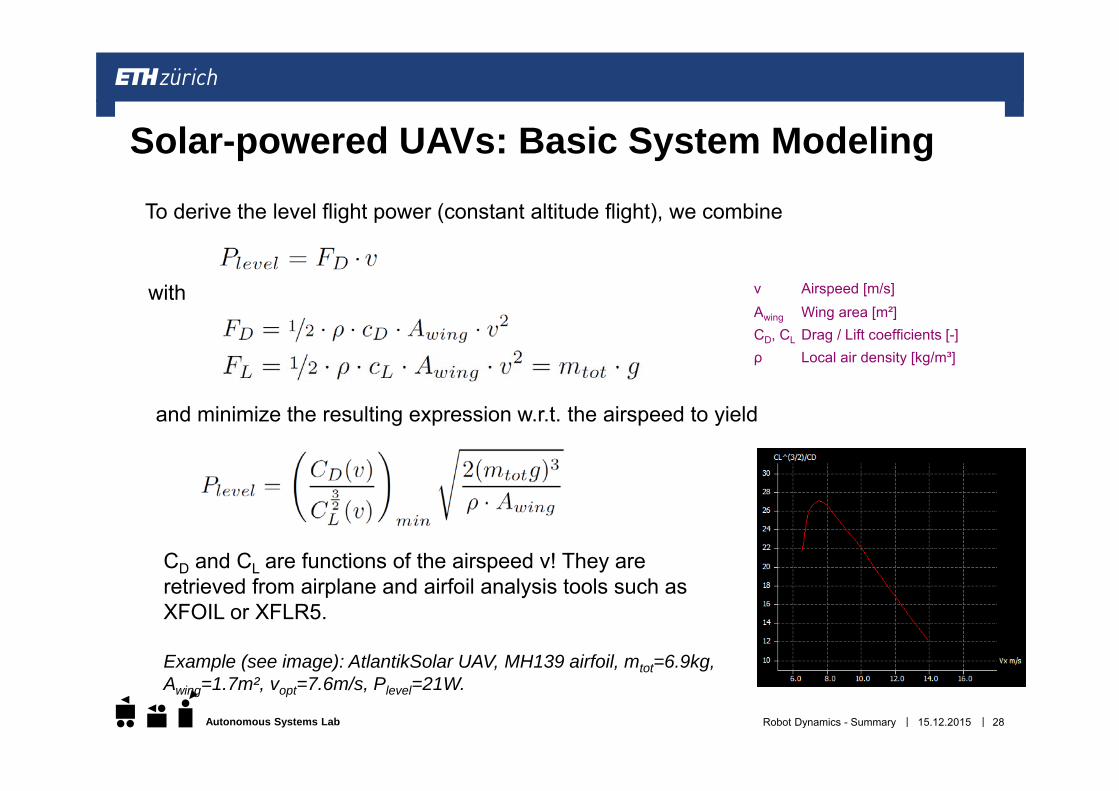
Solar-powered UAVs: Basic System Modeling
To derive the level flight power (constant altitude flight), we combine
v Airspeed [m/s]Awing Wing area [m²]CD, CL Drag / Lift coefficients [-]ρ Local air density [kg/m³]
with
and minimize the resulting expression w.r.t. the airspeed to yield
CD and CL are functions of the airspeed v! They areretrieved from airplane and airfoil analysis tools such asXFOIL or XFLR5.
Example (see image): AtlantikSolar UAV, MH139 airfoil, mtot=6.9kg, Awing=1.7m², vopt=7.6m/s, Plevel=21W.
||Autonomous Systems Lab 15.12.2015Robot Dynamics - Summary 29
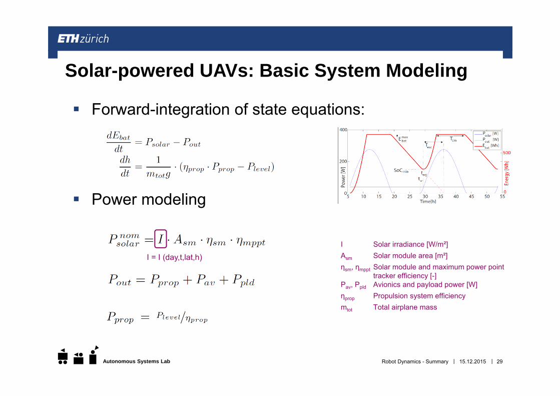
Solar-powered UAVs: Basic System Modeling
Forward-integration of state equations:
Power modeling
I Solar irradiance [W/m²]Asm Solar module area [m²]ηsm, ηmppt Solar module and maximum power point
tracker efficiency [-]Pav, Ppld Avionics and payload power [W]ηprop Propulsion system efficiencymtot Total airplane mass
I = I (day,t,lat,h)
||Autonomous Systems Lab
Saturday 13.02.2016, 9:00 – 11:00
4 A4-pages personal summary
Combination of Calculations, similar to exercises, but simpler and solvable without
computer Comprehension questions
More information about potential questions and example exam will be sent to you in the next days.
15.12.2015Robot Dynamics - Summary 30
Exam
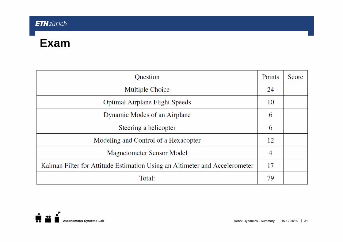
||Autonomous Systems Lab 15.12.2015Robot Dynamics - Summary 31
Exam
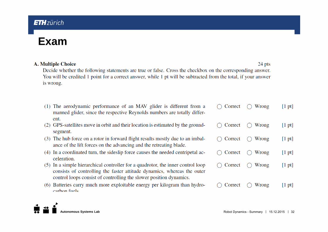
||Autonomous Systems Lab 15.12.2015Robot Dynamics - Summary 32
Exam
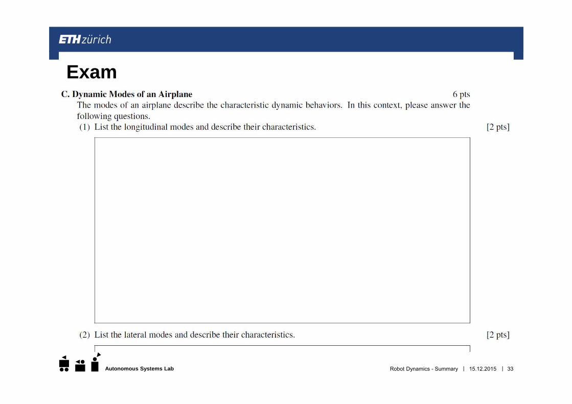
||Autonomous Systems Lab 15.12.2015Robot Dynamics - Summary 33
Exam