Embed Size (px)
Citation preview

2067-1
Joint ICTP/IAEA Workshop on Irradiation-induced Embrittlement ofPressure Vessel Steels
Enrico Lucon
23 - 27 November 2009
Italy*
Surveillance Programs for Monitoring the Integrity of the Reactor Pressure Vessel(RPV)

Enrico Lucon
Joint ICTP/IAEA Workshop Trieste, 23‐27 November 2009
Outline
GeneralitiesUS surveillance programs
Design of a surveillance program for LWR pressure vessels (ASTM E185‐02, E900‐02)Performing, analyzing and interpreting surveillance results (ASTM E2215‐02, E636‐02)
Other types of surveillance programsOther types of surveillance programsGermanyFranceFranceJapanWWER reactors (Eastern European countries)WWER reactors (Eastern European countries)
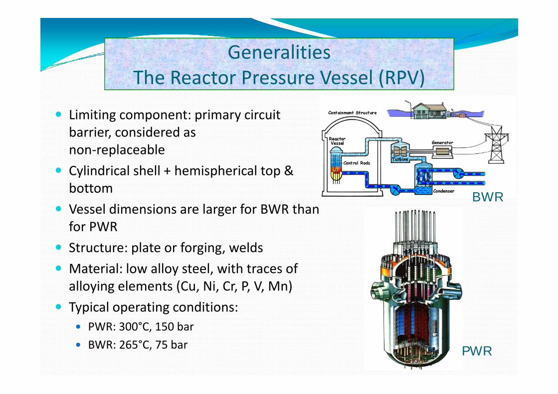
GeneralitiesThe Reactor Pressure Vessel (RPV)
Limiting component: primary circuit barrier, considered asnon‐replaceablenon replaceable
Cylindrical shell + hemispherical top & bottom
BWRVessel dimensions are larger for BWR than for PWR
BWR
Structure: plate or forging, welds
Material: low alloy steel, with traces of alloying elements (Cu Ni Cr P V Mn)alloying elements (Cu, Ni, Cr, P, V, Mn)
Typical operating conditions:PWR: 300°C, 150 bar,
BWR: 265°C, 75 bar PWR
GeneralitiesMonitoring the integrity of RPV’s
I di i i d d d i f h h i l i f h RPVIrradiation induces degradation of the mechanical properties of the RPV material
• increase of yield strength HARDENING• increase of yield strength HARDENING
• increase of DBTT EMBRITTLEMENT
Fracture toughness will accordingly be affectedFracture toughness will accordingly be affected
Irradiation and therefore degradation is less severe for BWR than for PWR, nevertheless it must be monitored,
At the conditions of operation as well as accidental ones, fracture should be avoided
Available technology at the time legislation was written:• (Pellini) Drop Weight Test
• Charpy Impact Test
• Plane Strain Fracture Toughness Test (KIc)
Generalities ‐ Evolution of fracture toughness according to the US legislation
• Fracture toughness (KIc) measurements previously required large samples prohibitive for irradiated materials
• Legislation (ASME code) assumes a lower bound fractureLegislation (ASME code) assumes a lower bound fracture toughness curve indexed by RTNDTRT i b d bi ti f P lli i d i ht• RTNDT is based on a combination of Pellini drop weight test (NDT) and Charpy impact test results
• Upon irradiation, the following assumption is made:
∆ ∆∆RTNDT = ∆T41J
Design of surveillance programsfor LWR pressure vesselsfor LWR pressure vessels
‐ ASTM E185‐02 ‐
Scope: “designing a surveillance program for monitoring the radiation‐induced changes in themonitoring the radiation induced changes in the mechanical properties of ferritic materials in the beltline of LWR vessels”beltline of LWR vessels”
Applicability: “all LWR vessels for which the predicted maximum fast neutron fluence (E > 1 MeV) at the end of the design lifetime (EOL)MeV) at the end of the design lifetime (EOL) exceeds 1 × 10¹⁷ n/cm² at the inside surface of the vessel”vessel
‐ ASTM E185‐02 –Criteria for implementing surveillance programs
The surveillance program must be planned and implemented in order to ensure that:implemented in order to ensure that:a) capsule exposures (fluences) can be related to
beltline exposures
b) surveillance materials are representative of thoseb) surveillance materials are representative of those materials most likely to limit the operation of the vessel (i e most irradiation sensitive)vessel (i.e. most irradiation‐sensitive)
c) tests yield results useful for the evaluation of radiation effects on the reactor vessel
‐ ASTM E185‐02 –Test Materials (I)
M t i l S l tiMaterials SelectionActual materials used for fabricating the beltline of the RPV or from
ld t t hi th RPV ld( )weldments matching the RPV weld(s)
Minimum: one heat of base metal + one weld (only required if there is a weld in the beltline)there is a weld in the beltline)
Most limiting base and weld materials have to be included in the surveillance programsurveillance program
→ choice to be made on the basis of the highest EOL adjusted reference temperature (ART), calculated in accordance withreference temperature (ART), calculated in accordance with ASTM E900‐02
Heat‐Affected Zone (HAZ) material no longer needs to be included(but should be kept in the archives)

‐ ASTM E185‐02 –Test Materials (II)
Chemical Analysis RequirementsChemical Analysis Requirements
Available chemical composition information for the ill t i l h ld t l t i l d P S C V Sisurveillance materials should at least include: P, S, Cu, V, Si,
Mn, Ni
Archive materialsFull‐thickness sections of the original materials (plates, forgings and welds) should be retained
Enough material to fill up six additional capsules should be available
HAZ associated with archive weld material should also be retained
‐ ASTM E185‐02 –Test Specimens
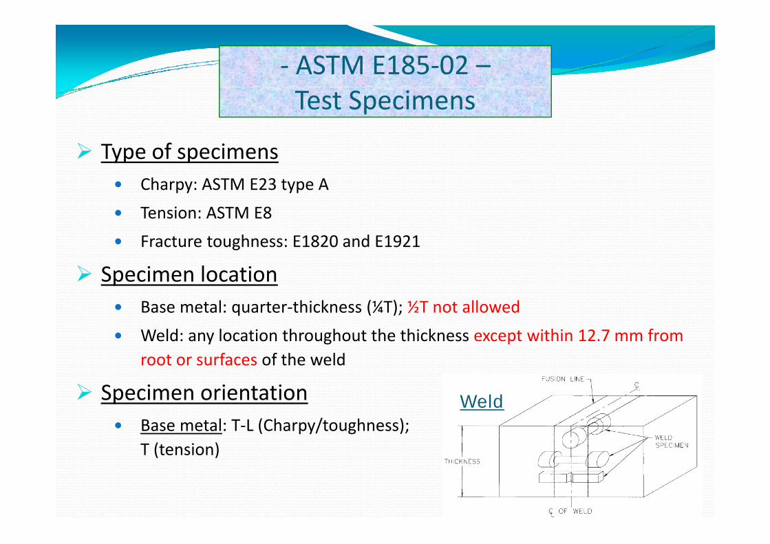
Type of specimensType of specimensCharpy: ASTM E23 type A
Tension: ASTM E8Tension: ASTM E8
Fracture toughness: E1820 and E1921
Specimen locationSpecimen locationBase metal: quarter‐thickness (¼T); ½T not allowed
Weld: any location throughout the thickness except within 12 7 mm fromWeld: any location throughout the thickness except within 12.7 mm from root or surfaces of the weld
Specimen orientation W ldSpecimen orientationBase metal: T‐L (Charpy/toughness);T (tension)
Weld
( )

‐ ASTM E185‐02 –Minimum number of specimens
Unirradiated baseline specimensUnirradiated baseline specimens
15 Charpy specimens for each material
6 tension specimens for both materials (at least 2 tests at room temperature and 2 at RPV operating temperature)
8 fracture toughness specimens
Irradiated specimens
‐ ASTM E185‐02 –Irradiation requirements (I)
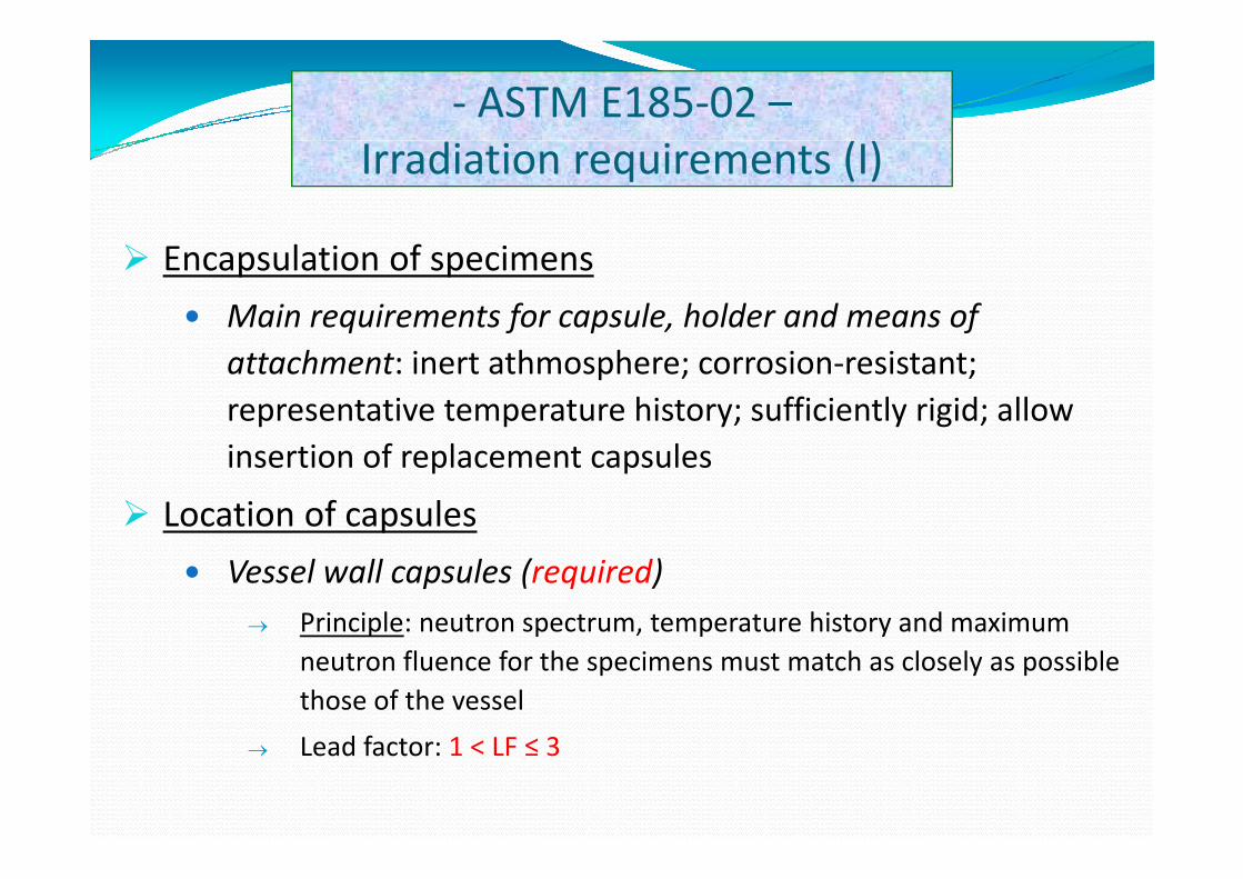
Encapsulation of specimens
Main requirements for capsule, holder and means of attachment: inert athmosphere; corrosion‐resistant; representative temperature history; sufficiently rigid; allow insertion of replacement capsules
Location of capsules
Vessel wall capsules (required)→ Principle: neutron spectrum, temperature history and maximum
neutron fluence for the specimens must match as closely as possible those of the vessel
L d f t 1 LF ≤ 3→ Lead factor: 1 < LF ≤ 3
‐ ASTM E185‐02 –Irradiation requirements (II)
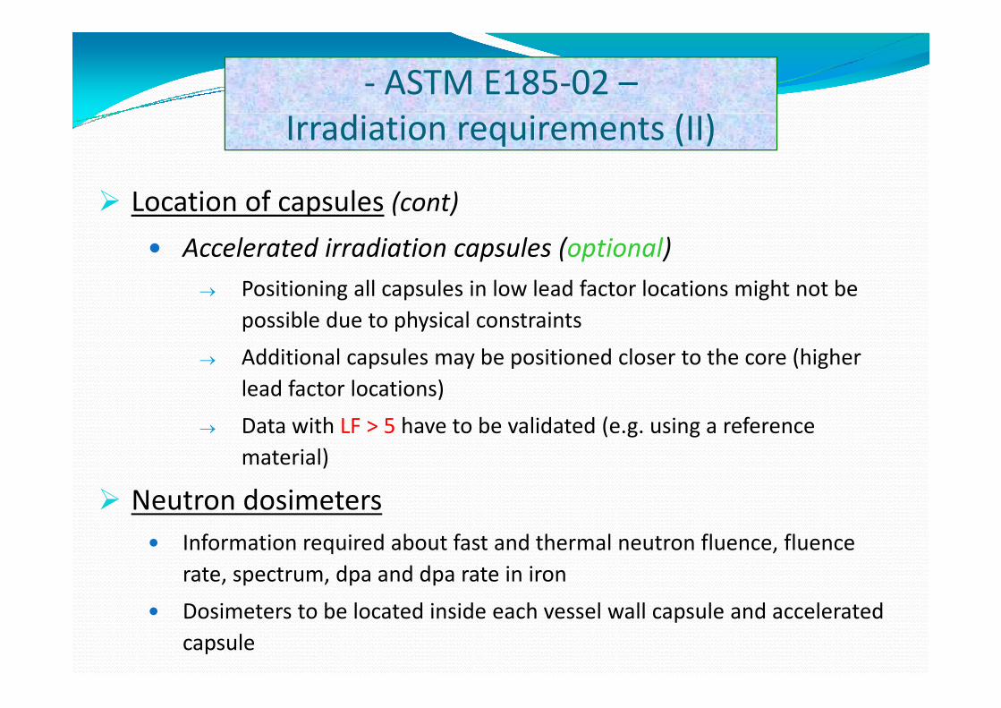
L ti f l ( )Location of capsules (cont)
Accelerated irradiation capsules (optional)→ Positioning all capsules in low lead factor locations might not be
possible due to physical constraints
Additional capsules may be positioned closer to the core (higher→ Additional capsules may be positioned closer to the core (higher lead factor locations)
→ Data with LF > 5 have to be validated (e.g. using a reference ( g gmaterial)
Neutron dosimetersInformation required about fast and thermal neutron fluence, fluence rate, spectrum, dpa and dpa rate in iron
Dosimeters to be located inside each vessel wall capsule and accelerated capsule
‐ ASTM E185‐02 –f i l & i iReference Materials & Temperature Monitoring
Use of a reference material is optional
Aim: providing an independent check for deviations from expected surveillance conditions (e.g. temperature, fluence rate, spectrum)
Examples: HSST plates; JRQ
T f l h ld b i d dTemperature of reactor coolant should be monitored and recorded
Optionally, temperature monitors can be included in the capsules (low melting point elements or eutectic alloys)
‐ ASTM E185‐02 –b f l d i hd l S h d lNumber of Capsules and Withdrawal Schedule
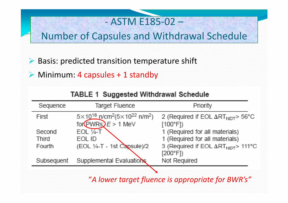
Basis: predicted transition temperature shift
Minimum: 4 capsules + 1 standbyp y
“A lower target fluence is appropriate for BWR’s”
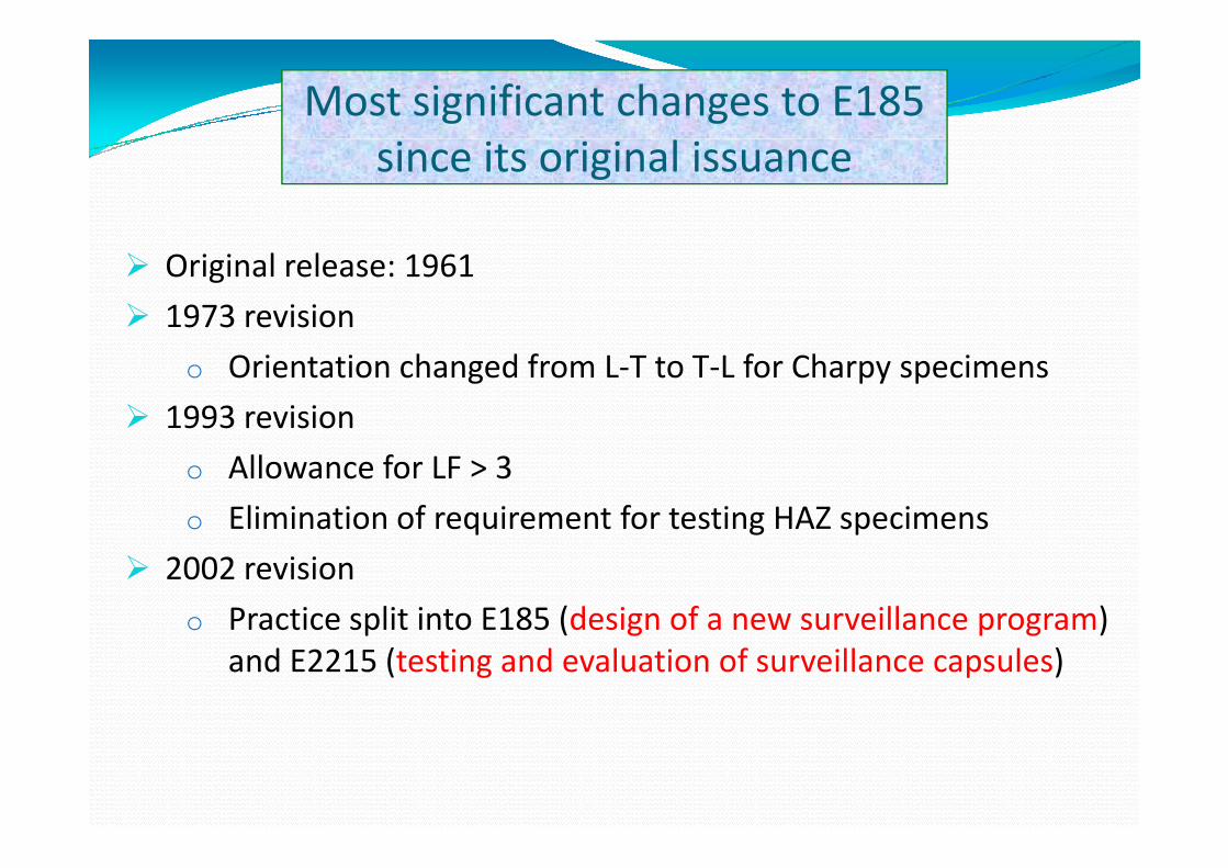
Most significant changes to E185since its original issuance
Original release: 1961
1973 revision
o Orientation changed from L‐T to T‐L for Charpy specimens
1993 revision
o Allowance for LF > 3
o Elimination of requirement for testing HAZ specimensq g p
2002 revision
o Practice split into E185 (design of a new surveillance program) p ( g p g )and E2215 (testing and evaluation of surveillance capsules)
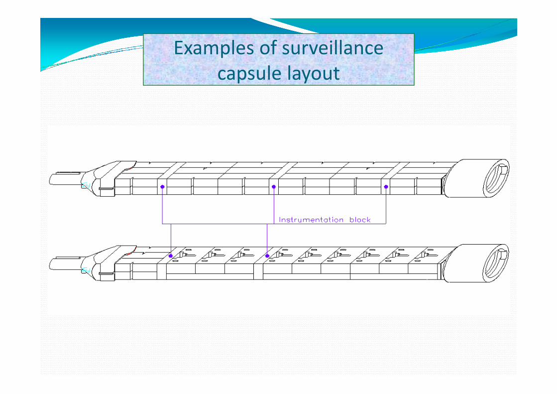
Examples of surveillancecapsule layout
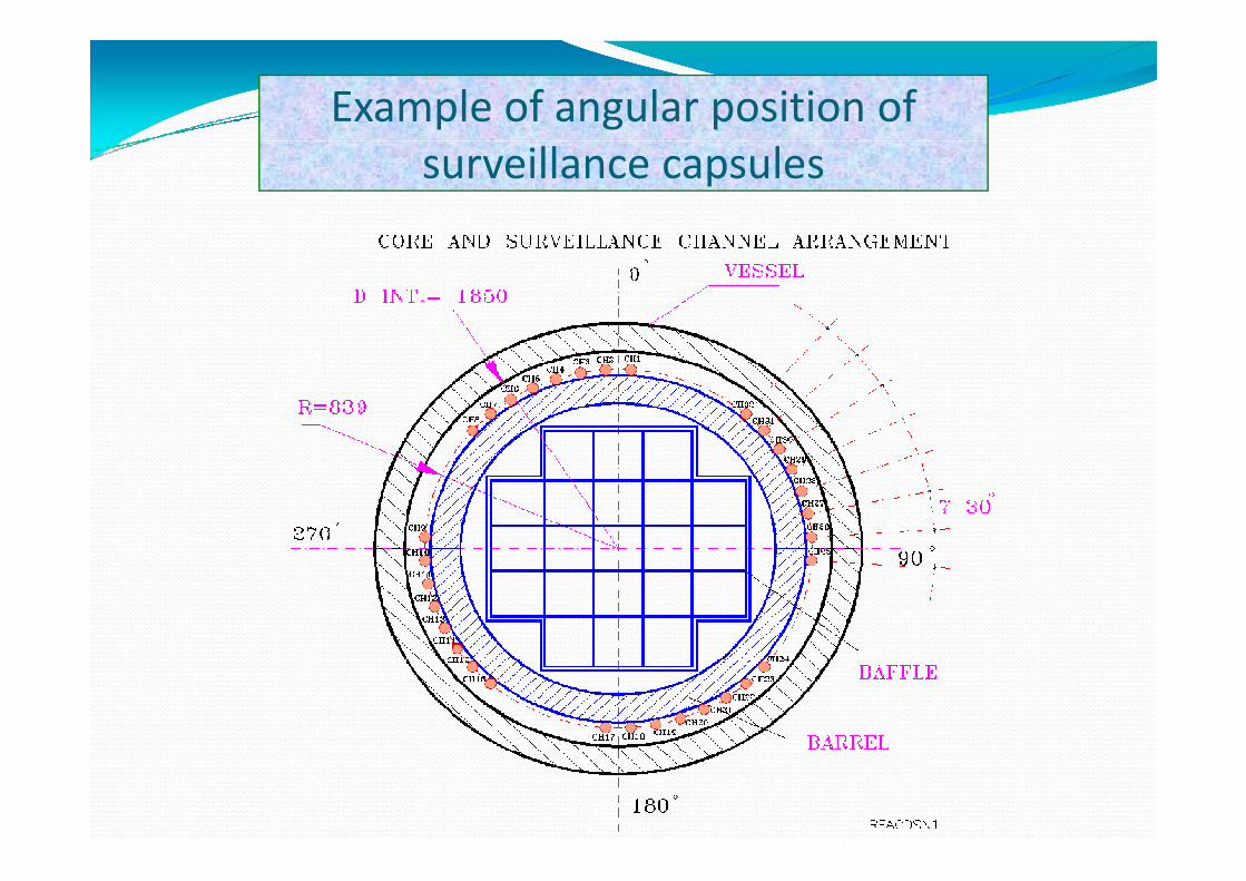
Example of angular position of surveillance capsules

Prediction of radiation‐induced transition temperature shiftf p f‐ ASTM E900‐02 ‐
Applicability requirementsA533B Cl.1 & 2, A302 Gr. B & B (modified), A508 Cl.2 & 3( )
Copper contents between 0 and 0.50 wt%
Nickel contents between 0 and 1.3 wt%
Phosphorous contents between 0 and 0.0025 wt%
Irradiation temperatures between 260 and 299 °C
Neutron fluence between 1 × 10¹⁶ and 8 × 10¹⁹ n/cm²(E > 1 MeV)
Neutron fluence rate between 2 × 10⁸ and 1 × 10¹² n/cm²s (E > 1 MeV)Neutron fluence rate between 2 × 10⁸ and 1 × 10¹² n/cm²s (E > 1 MeV)
Source: statistical analysis of irradiated material database (M 2000)(May 2000)
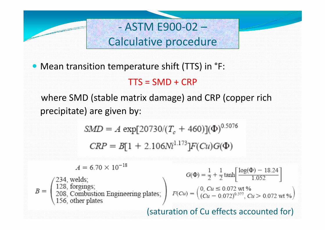
‐ ASTM E900‐02 –Calculative procedure
h f ( ) °Mean transition temperature shift (TTS) in °F:
TTS = SMD + CRP
where SMD (stable matrix damage) and CRP (copper rich precipitate) are given by:p p ) g y
(saturation of Cu effects accounted for)
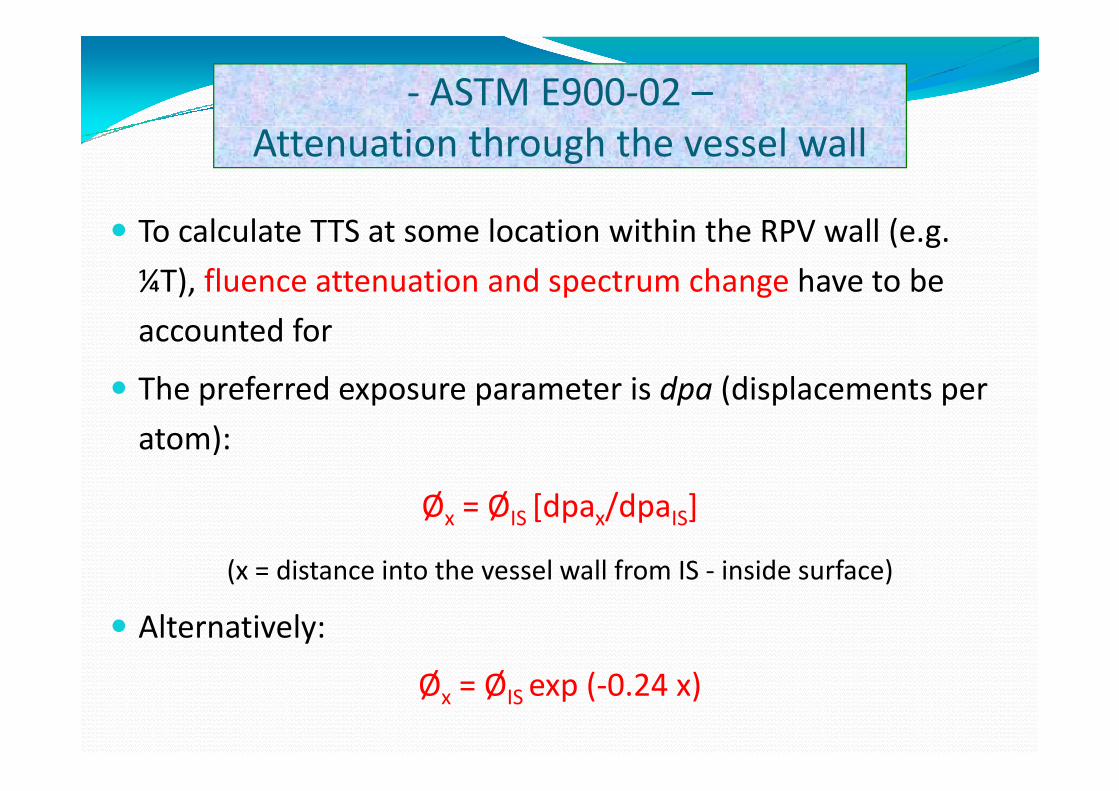
‐ ASTM E900‐02 –Attenuation through the vessel wall
To calculate TTS at some location within the RPV wall (e.g.
¼T), fluence attenuation and spectrum change have to be
accounted for
The preferred exposure parameter is dpa (displacements perThe preferred exposure parameter is dpa (displacements per
atom):
Øx = ØIS [dpax/dpaIS]
(x = distance into the vessel wall from IS ‐ inside surface)(x distance into the vessel wall from IS inside surface)
Alternatively:
Øx = ØIS exp (‐0.24 x)
‐ ASTM E900‐02 –Uncertainty‐related issues
d d f h lStandard error of the correlation:
22.0°F = 12.2°C
Role of phosphorous:identified as a potential embrittling agent in RPV steels;identified as a potential embrittling agent in RPV steels; however:
P ff t t b bi l id tifi d i th d t bP effect cannot be unambiguously identified in the database
a simple uncertainty analysis for the effect of P provided an ll ff t f 1 t 2°F th l b l t i toverall effect of 1 to 2°F on the global uncertainty
Within the database, a neutron fluence rate (flux) effect could not be unambiguously identified
Evaluation of surveillance capsules from LWR reactor vesselsASTM E2215 02‐ ASTM E2215‐02 ‐
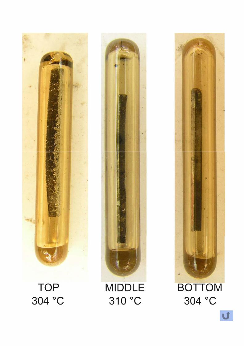
Determination of Capsule ConditionDetermination of Capsule ConditionVisual examination (identification marks; signs of damage)
Capsule content (comparison with capsule fabrication records;Capsule content (comparison with capsule fabrication records; corrosion or damage to the specimens; condition of thermal monitors, evidence of melting)monitors, evidence of melting)
Irradiation temperature history (PWR: coolant inlet temperature; BWR: recirculation temperature)p
Measurement of Irradiation ExposurePower history of the reactor prior to capsule removalPower history of the reactor prior to capsule removal
Determination of neutron fluence rate, energy spectrum, neutron fluence, dpa rate and dpa in accordance with ASTM E853 and E560, p p
‐ ASTM E2215‐02 –Measurement of Mechanical Properties (I)
Tension testsMethods: E8 and E21
Test temperatures: RT, service temperature and one intermediate temperature
Measurements: Ry, Rm, Ru, εu, εt, RA
Charpy testsMethods: A370 and E23; instrumented tests are recommended (E636)
Test temperatures: selected in order to define the full energy transition curve ( h i T d h lf )(emphasis on T41J and upper shelf energy)
Measurements: impact energy, lateral expansion and percent shear fracture appearanceappearance
‐ ASTM E2215‐02 –Measurement of Mechanical Properties (II)
d ( l)Hardness tests (optional)Methods: A370
To be performed on irradiated Charpy specimens
Fracture toughness tests (optional)Supplemental fracture toughness tests according to E636
Upper shelf: E1820 (J‐integral method)
( )Ductile‐to‐brittle transition: E1921 (reference temperature)
Broken Charpy specimens may be reconstituted forBroken Charpy specimens may be reconstituted for supplemental Charpy and/or fracture toughness testing in accordance with E1253accordance with E1253
‐ ASTM E2215‐02 –Evaluation of Test Data (I)
Tension testsAim: determining the amount of radiation strengthening by comparison with
i di d il dunirradiated tensile data
Data can be supplemented by hardness measurements
Ch t tCharpy testsCurve fitting: average curves for impact energy, lateral expansion and SFA determined by statistical fitting to a hyperbolic tangent function (preferreddetermined by statistical fitting to a hyperbolic tangent function (preferred method)
Index temperatures: 41 J and 0.89 mm
Upper Shelf Energy: average for specimens having nominally 100% shear (SFA ≥ 95%)
Radiation‐induced changes: by comparison with unirradiated Charpy data
‐ ASTM E2215‐02 –Evaluation of Test Data (II)
Reference materialMeasured irradiation response should fall within the scatter band of the pre‐existing database
In case of excessive scatter, the cause should be investigated
d ( i l)Hardness tests (optional)Data may be correlated to the yield strength of the material
Fracture toughness tests (optional)Upper shelf fracture toughness: resistance to crack initiation and extension (J‐integral, E1820)
Transition fracture toughness: reference temperature To according to E1921 can be used to define an alternative reference temperature (RT ASMEcan be used to define an alternative reference temperature (RTTo, ASME Code Case N‐629)
Supplemental surveillance tests‐ ASTM E636‐02 ‐
Scope
Acquiring additional information on radiation‐induced changesAcquiring additional information on radiation induced changes in fracture toughness, notch ductility and tensile strength of RPV steels
Supplemental Mechanical Property Tests
Fracture toughness test (static/dynamic)Fracture toughness test (static/dynamic)
Precracked Charpy impact test (dynamic toughness)
I t t d Ch V t h t t (ISO 14556)Instrumented Charpy V‐notch test (ISO 14556)
Other mechanical property tests (e.g. miniature testing t h i )techniques)
Several countries in the worldfollow the US regulations
Belgium
Spainp
The Netherlands
S dSweden
Mexico
Other national surveillance programs addressed:GermanyGermany
France
Japanp
WWER countries
Surveillance programs in Germany (1)Surveillance programs in Germany (1)
Reference standard: KTA Safety Standard 3203Reference standard: KTA Safety Standard 3203
Surveillance programs consist of three sets:first set: unirradiated material datafirst set: unirradiated material data
second set: ~ ½ of design fluence (PWR: 5 × 10¹⁸ n/cm² for 32 EFPY)
third set: design life fluence or abovethird set: design life fluence or above
Materials to be included:Design fluence < 1 × 10¹⁹ n/cm²: one base metal one weld metalDesign fluence < 1 × 10¹⁹ n/cm²: one base metal, one weld metal
Design fluence > 1 × 10¹⁹ n/cm²: two base metals, one weld metal
Specimen types:Specimen types:Charpy V (12 per material/set)
Tensile (3 per material/set)Tensile (3 per material/set)
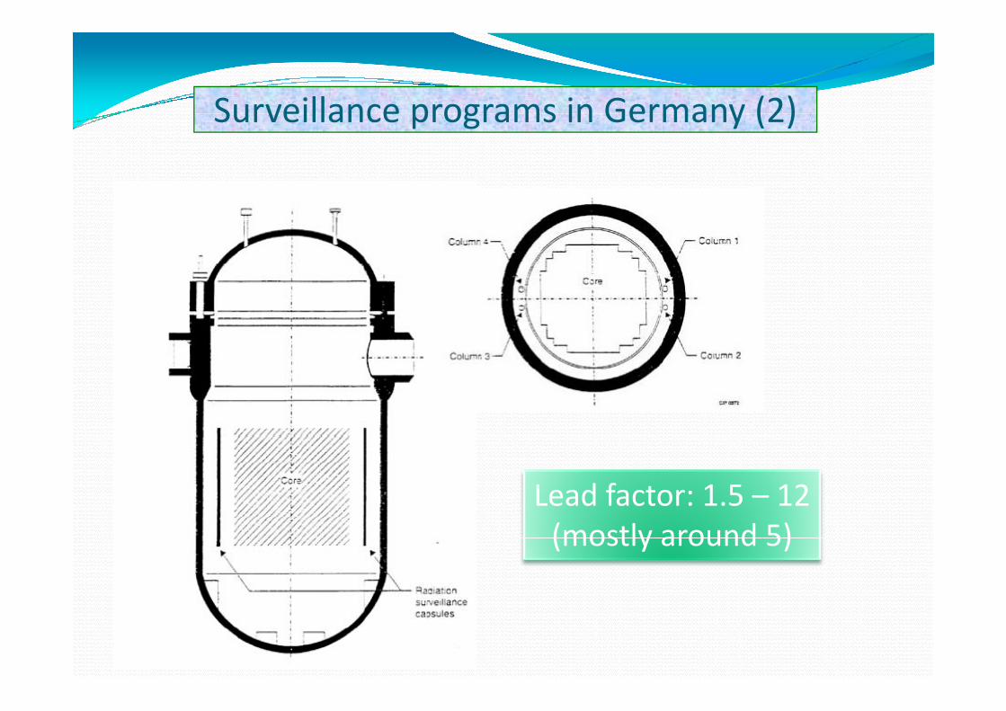
Surveillance programs in Germany (2)Surveillance programs in Germany (2)
Lead factor: 1.5 – 12(mostly around 5)
Surveillance programs in FranceSurveillance programs in France
Reference standard RSE M CodeReference standard: RSE‐M Code
Surveillance programs are similar to US programscapsules removed from reactor
specimens subjected to Charpy testing
measured shifts compared with predicted values (different correlation used)
Specified limit for the lead factor: less than 3
Archive material stored for future use
Some changes under study to support life extension from 40 to 60 years40 to 60 years
Surveillance programs in Japan
Reference standard: JEAC 4201 (similar to ASTM E185)
Six capsules inserted into PWR vesselsSix capsules inserted into PWR vessels
Specimens: CVN, tensile and 12.7 mm‐thick C(T)
Materials: base (1 or 2), weld and HAZ
Fracture toughness tests:ductile‐to‐brittle transition region
upper shelf (unloading compliance method)
Surveillance programs in WWER reactors (1)
Oldest design (WWER‐440/230) has no surveillance program
Newer designs (WWER‐440/213 and WWER‐1000) have surveillance programs
Specimens are placed in 10‐20 containers connected in chain; two chains constitute a set
Six sets are located in each unit
Planned withdrawal interval: 1, 3, 5, 10 years
High lead factors: 6 to 18
Specimens for thermal ageing monitoring are also included (removed after 5 and 10 years)
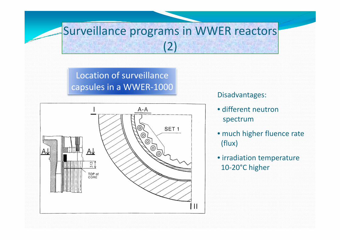
Surveillance programs in WWER reactors (2)
Location of surveillancecapsules in a WWER‐1000
Di d tDisadvantages:
• different neutronspectrumspectrum
• much higher fluence rate(flux)
• irradiation temperature10‐20°C higher
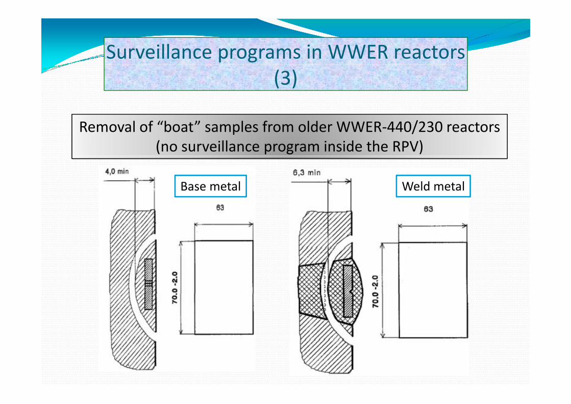
Surveillance programs in WWER reactors (3)
Removal of “boat” samples from older WWER‐440/230 reactors(no surveillance program inside the RPV)
Base metal Weld metal
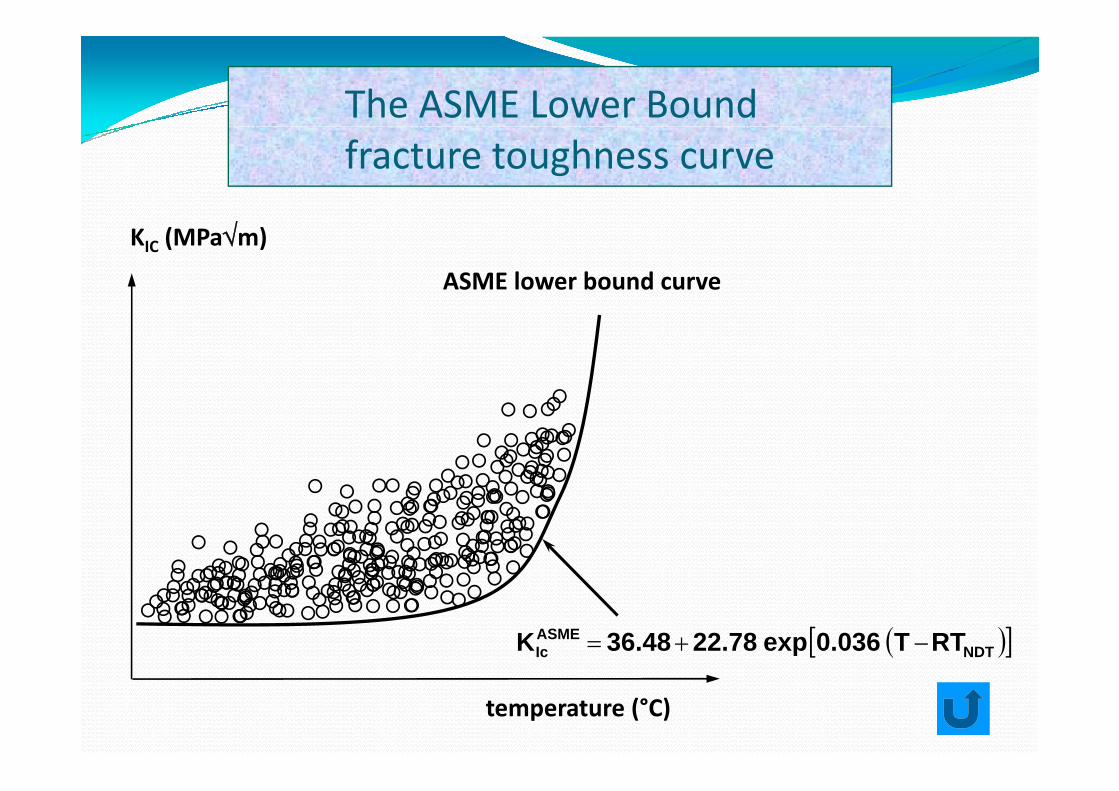
The ASME Lower Boundfracture toughness curve
ASME lower bound curve
KIC (MPa√m)
( )[ ]NDTASMEIc RTT 0.036exp22.7836.48K −+=
temperature (°C)
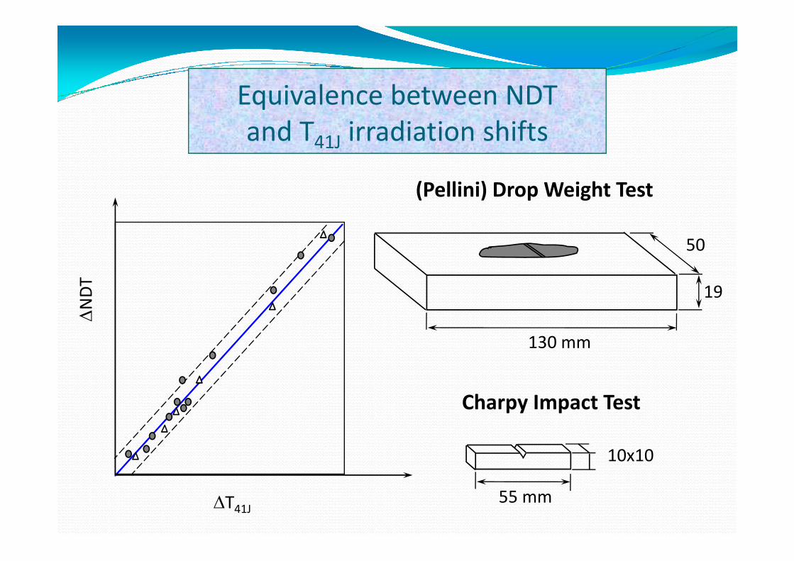
E i l b t NDTEquivalence between NDTand T41J irradiation shifts
(Pellini) Drop Weight Test
T
50
∆NDT
130 mm
19
130 mm
Charpy Impact Test
10x10
Charpy Impact Test
∆T41J 55 mm
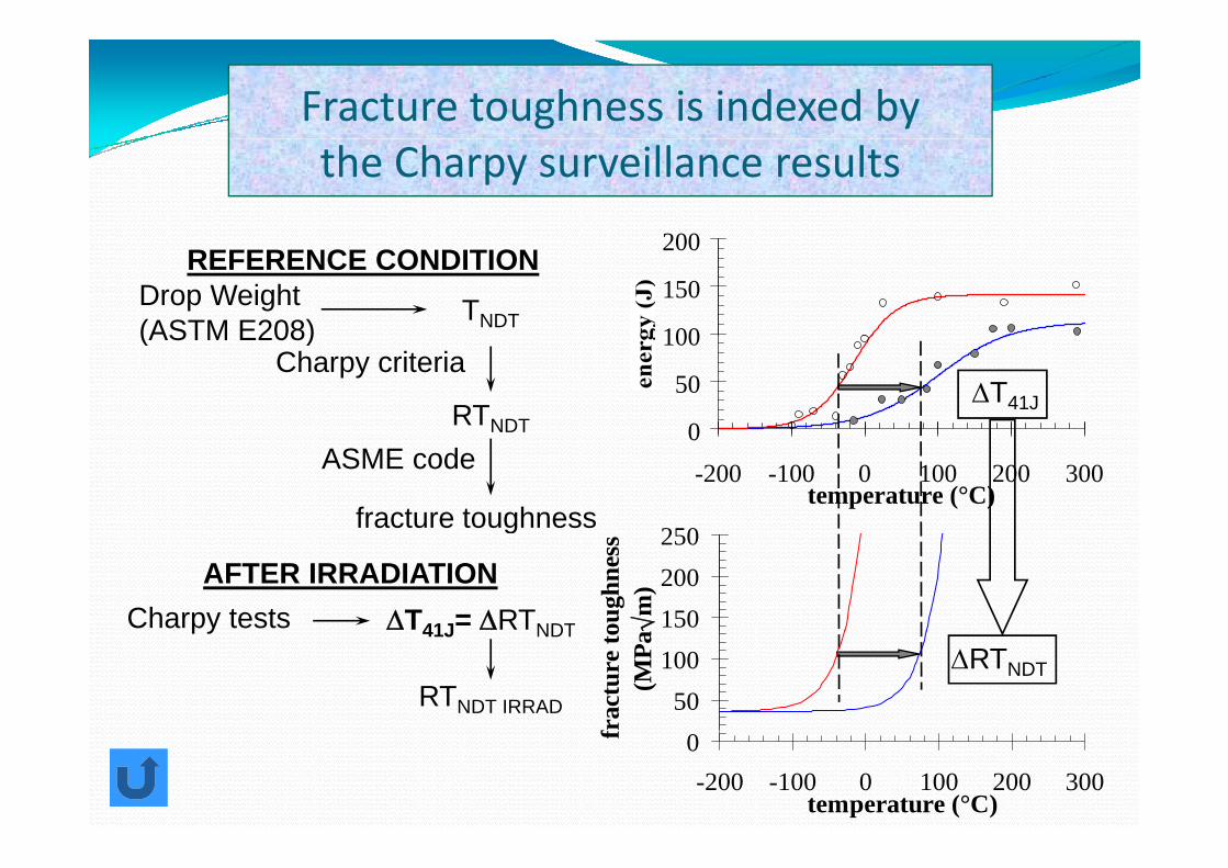
Fracture toughness is indexed bythe Charpy surveillance results
200
100
150
200
Drop Weight (ASTM E208)
TNDT
REFERENCE CONDITION
0
50
100
∆T41J
(ASTM E208)
RTNDT
Charpy criteria
0-200 -100 0 100 200 300
temperature (°C)250
ASME code
fracture toughness
150200250
ough
ness
√m
)
g
AFTER IRRADIATIONCharpy tests ∆T41J= ∆RTNDT
50100
frac
ture
to(M
Pa ∆RTNDT
py 41J NDT
RTNDT IRRAD
0-200 -100 0 100 200 300
temperature (°C)
f