Embed Size (px)
DESCRIPTION
CONNECTION
Citation preview

APPENDIX to TALAT Lectures 2301 and 2302
FIGURES AND TABLES FROM EUROCODE 9
Updated in the aluMATTER project 2008
18 pages
TALAT 2302 – Appendix 2
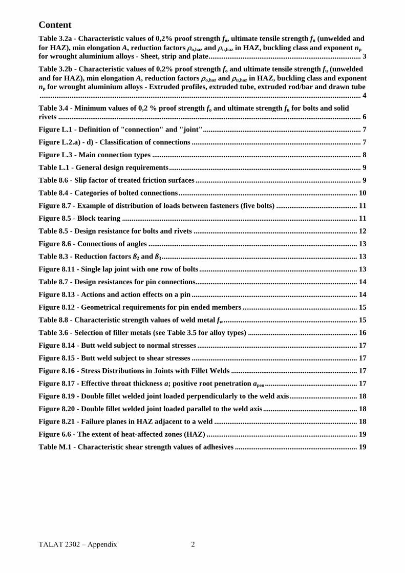
Content Table 3.2a - Characteristic values of 0,2% proof strength fo, ultimate tensile strength fu (unwelded and for HAZ), min elongation A, reduction factors ρo,haz and ρu,haz in HAZ, buckling class and exponent np for wrought aluminium alloys - Sheet, strip and plate................................................................................. 3 Table 3.2b - Characteristic values of 0,2% proof strength fo and ultimate tensile strength fu (unwelded and for HAZ), min elongation A, reduction factors ρo,haz and ρu,haz in HAZ, buckling class and exponent np for wrought aluminium alloys - Extruded profiles, extruded tube, extruded rod/bar and drawn tube........................................................................................................................................................................... 4 Table 3.4 - Minimum values of 0,2 % proof strength fo and ultimate strength fu for bolts and solid rivets ................................................................................................................................................................. 6 Figure L.1 - Definition of "connection" and "joint".................................................................................... 7 Figure L.2.a) - d) - Classification of connections .......................................................................................... 7 Figure L.3 - Main connection types ............................................................................................................... 8 Table L.1 - General design requirements...................................................................................................... 9 Table 8.6 - Slip factor of treated friction surfaces ........................................................................................ 9 Table 8.4 - Categories of bolted connections............................................................................................... 10 Figure 8.7 - Example of distribution of loads between fasteners (five bolts) ........................................... 11 Figure 8.5 - Block tearing ............................................................................................................................. 11 Table 8.5 - Design resistance for bolts and rivets ....................................................................................... 12 Figure 8.6 - Connections of angles ............................................................................................................... 13 Table 8.3 - Reduction factors ß2 and ß3........................................................................................................ 13 Figure 8.11 - Single lap joint with one row of bolts .................................................................................... 13 Table 8.7 - Design resistances for pin connections...................................................................................... 14 Figure 8.13 - Actions and action effects on a pin ........................................................................................ 14 Figure 8.12 - Geometrical requirements for pin ended members ............................................................. 15 Table 8.8 - Characteristic strength values of weld metal fw....................................................................... 15 Table 3.6 - Selection of filler metals (see Table 3.5 for alloy types) .......................................................... 16 Figure 8.14 - Butt weld subject to normal stresses ..................................................................................... 17 Figure 8.15 - Butt weld subject to shear stresses ........................................................................................ 17 Figure 8.16 - Stress Distributions in Joints with Fillet Welds ................................................................... 17 Figure 8.17 - Effective throat thickness a; positive root penetration apen ................................................. 17 Figure 8.19 - Double fillet welded joint loaded perpendicularly to the weld axis.................................... 18 Figure 8.20 - Double fillet welded joint loaded parallel to the weld axis .................................................. 18 Figure 8.21 - Failure planes in HAZ adjacent to a weld ............................................................................ 18 Figure 6.6 - The extent of heat-affected zones (HAZ) ................................................................................ 19 Table M.1 - Characteristic shear strength values of adhesives ................................................................. 19

Table 3.2a - Characteristic values of 0,2% proof strength fo, ultimate tensile strength fu (unwelded and for HAZ), min elongation A, reduction factors ρo,haz and ρu,haz in HAZ, buckling class and exponent np for wrought aluminium alloys - Sheet, strip and plate
fo 1) fu A50
1) 6) fo,haz2) fu,haz
2)HAZ-factor2)Alloy
EN-AW
Temper 1)Thick-ness mm 1) N/mm2 % N/mm2 ρo,haz
1) ρu,haz
BC 4)
np1), 5)
H14 | H24/H34 ≤ 6 | 3 180 | 170 220 1 | 3 0,42 | 0,44 0,70 B 23 | 183004 H16 | H26/H36 ≤ 4 | 3 200 | 190 240 1 | 3 75 155
0,38 | 0,39 0,65 B 25 | 20H14 | H24 ≤ 6 | 3 150 | 130 170 1 | 4 0,37 | 0,43 0,68 B 38 | 183005 H16 | H26 ≤ 4 | 3 175 | 160 195 1 | 3 56 115
0,32 | 0,35 0,59 B 43 | 24H14 | H24 ≤ 25| 12,5 120 | 110 140 2 | 4 0,37 | 0,40 0,64 B 31 | 203103 H16 | H26 ≤ 4 145 | 135 160 1 | 2 44 90
0,30 | 0,33 0,56 B 48 | 28O/H111 ≤ 50 35 100 15 35 100 1 1 B 5
H12 | H22/H32 ≤ 12,5 95 | 80 125 2 | 4 0,46 | 0,55 0,80 B 18 | 115005/ 5005A
H14 | H24/H34 ≤ 12,5 120 | 110 145 2 | 3 44 100 0,37 | 0,40 0,69 B 25 | 17
H12 | H22/H32 ≤ 40 160 | 130 210 4 | 5 0,50 | 0,62 0,81 B 17 | 105052 H14 | H24/H34 ≤ 25 180 | 150 230 3 | 4 80 170
0,44 | 0,53 0,74 B 19 | 11O / H111 ≤ 100 80 190 12 80 190 1 1 B 6 5049
H14 | H24/H34 ≤ 25 190 | 160 240 3 | 6 100 190 0,53 | 0,63 0,79 B 20 | 125454 O/H111 ≤ 80 85 215 12 85 215 1 1 B 5
H14|H24/H34 ≤ 25 220 | 200 270 2 | 4 105 215 0,48 | 0,53 0,80 B 22 | 155754 O/H111 ≤ 100 80 190 12 80 190 1 1 B 6
H14|H24/H34 ≤ 25 190 | 160 240 3 | 6 100 190 0,53 | 0,63 0,79 B 20 | 12≤ 50 125 275 11 125 275 B O/H111
50<t≤80 115 270 14 3) 115 270 1 1
B 6
H12|H22/H32 ≤ 40 250 | 215 305 3 | 5 0,62 | 0,72 0,90 B 22 | 145083
H14|H24/H34 ≤ 25 280 | 250 340 2 | 4 155 275 0,55 | 0,62 0,81 A 22 | 14
T4 / T451 ≤ 12,5 110 205 12 95 150 0,86 0,73 B 8 T6 / T651 ≤ 12,5 240 290 6 6061
T651 12,5<t≤80 240 290 6 3) 115 175 0,48 0,60 A 23
T4 / T451 ≤ 12,5 110 205 12 100 160 0,91 0,78 B 8 T61/T6151 ≤12,5 205 280 10 0,61 0,66 A 15
T6151 12,5<t≤100 200 275 12 3) 0,63 0,67 A 14 ≤ 6 260 310 6 0,48 0,60 A 25 T6/T651
6<t≤12,5 255 300 9 0,49 0,62 A 27
6082
T651 12,5<t≤100 240 295 7 3)
125 185
0,52 0,63 A 21 T6 ≤ 12,5 7
7020 T651 ≤ 40
280 350 9 3) 205 280 0,73 0,80 A 19
H14 | H24 ≤ 12,5 110 | 100 125 2 | 3 0,34 | 0,37 0,68 37 | 228011A H16 | H26 ≤ 4 130 | 120 145 1 | 2 37 85
0,28 | 0,31 0,59 B
33 | 331) If two (three) tempers are specified in one line, tempers separated by “|” have different technological values but separated by “/” have same values. (The tempers show differences for fo , A and np.). 2) The HAZ-values are valid for MIG welding and thickness up to 15mm. For TIG welding strain hardening alloys (3xxx, 5xxx and 8011A) up to 6 mm the same values apply, but for TIG welding precipitation hardening alloys (6xxx and 7xxx) and thickness up to 6 mm the HAZ values have to be multiplied by a factor 0,8 and so the ρ-factors. For higher thickness – unless other data are available – the HAZ values and ρ-factors have to be further reduced by a factor 0,8 for the precipitation hardening alloys (6xxx and 7xxx) and by a factor 0,9 for the strain hardening alloys (3xxx, 5xxx and 8011A). These reductions do not apply in temper O. 3) Based on A )( 65,5 oA4) BC = buckling class, see 6.1.4.4, 6.1.5 and 6.3.1.
A= , not A50.
5) n-value in Ramberg-Osgood expression for plastic analysis. It applies only in connection with the listed fo-value. 6) The minimum elongation values indicated do not apply across the whole range of thickness given, but mostly to the thinner materials. In detail see EN 485-2.
TALAT 2302 – Appendix 3

TALAT 2302 – Appendix 4
Table 3.2b - Characteristic values of 0,2% proof strength fo and ultimate tensile strength fu (unwelded and for HAZ), min elongation A, reduction factors ρo,haz and ρu,haz in HAZ, buckling class and exponent np for wrought aluminium alloys - Extruded profiles, extruded tube, extruded rod/bar and drawn tube
fo 1) fu
1) A 5) 2) fo,haz
4), fu,haz4) HAZ-factor4)Alloy
EN-AW
Product form
Temper Thick- ness t mm 1) 3) N/mm2 % N/mm2 ρo,haz ρu,haz
BC 6)
np7)
ET, EP,ER/B O / H111, F, H112 t ≤ 200 110 270 12 110 270 1 1 B 5
H12/22/32 t ≤ 10 200 280 6 0,68 0,96 B 14 5083 DT
H14/24/34 t ≤ 5 235 300 4135 270
0,57 0,90 A 18
5454 ET, EP,ER/B O/H111 F/H112 t ≤ 200 85 200 16 85 200 1 1 B 5
ET, EP,ER/B O/H111 F/H112 t ≤ 150 80 180 14 80 180 1 1 B 6
5754 DT H14/
H24/H34 t ≤ 10 180 240 4 100 180 0,56 0,75 B 16
t ≤ 5 120 160 8 0,42 0,50 B 17 EP
T5 5 < t ≤ 25 100 140 8
50 80 0,50 0,57 B 14
ET,EP,ER/B t ≤ 15 140 170 8 0,43 0,59 A 24 DT
T6 t ≤ 20 160 215 12
60 100 0,38 0,47 A 16
EP,ET,ER/B T64 t ≤ 15 120 180 12 60 100 0,50 0,56 A 12 EP,ET,ER/B t ≤ 3 160 215 8 0,41 0,51 A 16
6060
EP T66
3 < t ≤ 25 150 195 8 65 110
0,43 0,56 A 18 EP,ET,ER/B,DT T4 t<25 110 180 50 95 150 0,86 0,83 B 8
6061 EP,ET,ER/B,DT T6 t ≤ 20 240 260 8 115 175 0,48 0,67 A 55 EP,ET,ER/B t ≤ 3 130 175 8 0,46 0,57 B 16
EP T5
3 < t ≤ 25 110 160 7 60 100
0,55 0,63 B 13 EP,ET,ER/B t ≤ 25 160 195 8 0,41 0,56 A 24
DT T6
t ≤ 20 190 220 10 65 110 0,34 0,50 A 31
EP,ET,ER/B t ≤ 10 200 245 8 0,38 0,53 A 22 EP 10 < t ≤ 25 180 225 8 0,42 0,58 A 21
6063
DT T66
t ≤ 20 195 230 10 75 130
0,38 0,57 A 28 t ≤ 5 225 270 8 0,51 0,61 A 25
5 < t ≤ 10 215 260 8 0,53 0,63 A 24 EP/O, ER/B T6 10 < t ≤ 25 200 250 8 0,58 0,66 A 20
t ≤ 5 215 255 8 0,53 0,65 A 26 6005A
EP/H, ET T6 5 < t ≤ 10 200 250 8
115 165
0,58 0,66 A 20 6106 EP T6 t≤10 200 250 8 95 160 0,48 0,64 A 20
EP,ET,ER/B T4 t ≤ 25 110 205 14 100 160 0,91 0,78 B 8 EP/O, EP/H T5 t ≤ 5 230 270 8 125 185 0,54 0,69 B 28
t ≤ 5 250 290 8 0,50 0,64 A 32 EP/O,EP/H ET
T6 5 < t ≤ 15 260 310 10 0,48 0,60 A 25
t ≤ 20 250 295 8 0,50 0,63 A 27 ER/B T6
20< t ≤150 260 310 8 0,48 0,60 A 25 t ≤ 5 255 310 8 0,49 0,60 A 22
6082
DT T6 5 < t ≤ 20 240 310 10
125 185
0,52 0,60 A 17

EP,ET,ER/B T6 t ≤ 15 290 350 10 0,71 0,80 A 23 EP,ET,ER/B T6 15<t <40 275 350 10 0,75 0,80 A 19 7020
DT T6 t ≤ 20 280 350 10 205 280
0,73 0,80 A 18
Key:
EP EP/H ER/B
- Extruded profiles - Extruded hollow profiles - Extruded rod and bar
EP/O ET DT
- Extruded open profiles - Extruded tube - Drawn tube
1): Where values are quoted in bold greater thicknesses and/or higher mechanical properties may be permitted in some forms see ENs and prENs listed in 1.2.1.3. In this case the Rp0,2 and Rm values can be taken as fo and fu. If using such higher values the corresponding HAZ-factors ρ have to be calculated acc. to expression (6.13) and (6.14) with the same values for fo,haz and 'fu,haz .2): Where minimum elongation values are given in bold, higher minimum values may be given for some forms or thicknesses. 3): According to EN 755-2: following rule applies: "If a profile cross-section is comprised of different thicknesses which fall in more than one set of specified mechanically property values, the lowest specified value should be considered as valid for the whole profile cross-section." Exception is possible and the highest value given may be used provided the manufacturer can support the value by an appropriate quality assurance certificate. 4) The HAZ-values are valid for MIG welding and thickness up to 15mm. For TIG welding strain hardening alloys (3xxx, 5xxx and 8011A) up to 6 mm the same values apply, but for TIG welding precipitation hardening alloys (6xxx and 7xxx) and thickness up to 6 mm the HAZ values have to be multiplied by a factor 0,8 and so the ρ-factors. For higher thickness – unless other data are available – the HAZ values and ρ-factors have to be further reduced by a factor 0,8 for the precipitation hardening alloys (6xxx and 7xxx) alloys and by a factor 0,9 for strain hardening alloys (3xxx, 5xxx and 8011A). These reductions do not apply in temper O. 5)
o6) BC = buckling class, see 6.1.4.4, 6.1.5 and 6.3.1.
AAA 65,5=
7) n-value in Ramberg-Osgood expression for plastic analysis. It applies only in connection with the listed fo-value (= minimum standardized value).
TALAT 2302 – Appendix 5

Table 3.4 - Minimum values of 0,2 % proof strength fo and ultimate strength fu for bolts and solid rivets
Material Type of fastener
Alloy Numerical
designation: EN AW-.
Alloy Chemical
designation: EN AW-
Temper or grade
Dia- meter
fo 7)
N/mm2 fu 7)
N/mm2
H111 ≤20 110 250 5019 AlMg5
H14,H34 ≤18 210 300 H111 ≤20 80 180
5754 AlMg3 H14/H34 ≤18 180 240
T4 ≤20 110 205
Solid
Rivets 1)
6082 AlSi1MgMn T6 ≤20 240 300
5754 ≤10 230 270
(AL1) 3) AlMg3 4)
10<d≤20 180 250
5019 ≤14 205 310
(AL2) 3) AlMg5 4)
14<d≤36 200 280
6082 ≤6 250 320
Aluminium alloy
Bolts 2)
(AL3) 3) AlSi1MgMn 4)
14<d≤36 260 310
4.6 ≤39 240 400 5.6 ≤39 300 500 6.8 ≤39 480 600 8.8 ≤39 640 800
Steel Bolts 5)
10.9 ≤39 900 1000 A2, A4 50 ≤39 210 500 A2, A4 70 ≤39 450 700
Stainless Steel Bolts 6)
A2, A4 80 ≤39 600 800 1) and 2) Aluminium bolts and rivets should be used only for connections of category A (bearing type, see Table 8.4). 3) Material designation according to EN 28839 4) No grade designation in EN 28839 5) Grade according to EN ISO 898-1 6) Designation and grade according to EN ISO 3506-1 7) The given values for solid rivets are the lesser values of EN 754 (drawn rods) or EN 1301 (drawn wire) of which solid rivets are manufactured by cold forming. For the 0,2-proof stress EN 1301 defines indeed only typical values, but the above given values can all be regarded as on the safe side. Anyway for the design of connections of category A (bearing mode) the ultimate strength value is the basis for the calculation of the bearing capacity of a bolt or a rivet.
(C)(B)
(N)
(W)
(W)
(B)
(N)
(C)
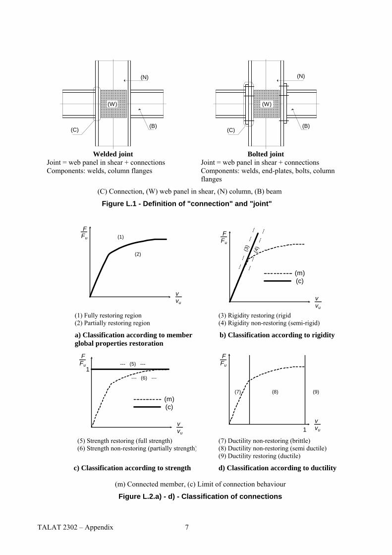
Welded joint
Joint = web panel in shear + connections Components: welds, column flanges
Bolted joint Joint = web panel in shear + connections Components: welds, end-plates, bolts, column flanges
(C) Connection, (W) web panel in shear, (N) column, (B) beam
Figure L.1 - Definition of "connection" and "joint"
FFu
vvu
(2)
(1)
FFu
vvu
---
---
(4)
---
---
---
---
(3)
---
---
(m)(c)
(1) Fully restoring region (2) Partially restoring region
(3) Rigidity restoring (rigid (4) Rigidity non-restoring (semi-rigid)
a) Classification according to member global properties restoration
b) Classification according to rigidity
--- (6) ---
--- (5) --- FFu
vvu
1
(m)(c)
FFu
vvu
(8)
1
(7) (9)
(5) Strength restoring (full strength) (6) Strength non-restoring (partially strength)
(7) Ductility non-restoring (brittle) (8) Ductility non-restoring (semi ductile) (9) Ductility restoring (ductile)
c) Classification according to strength d) Classification according to ductility
(m) Connected member, (c) Limit of connection behaviour
Figure L.2.a) - d) - Classification of connections
TALAT 2302 – Appendix 7
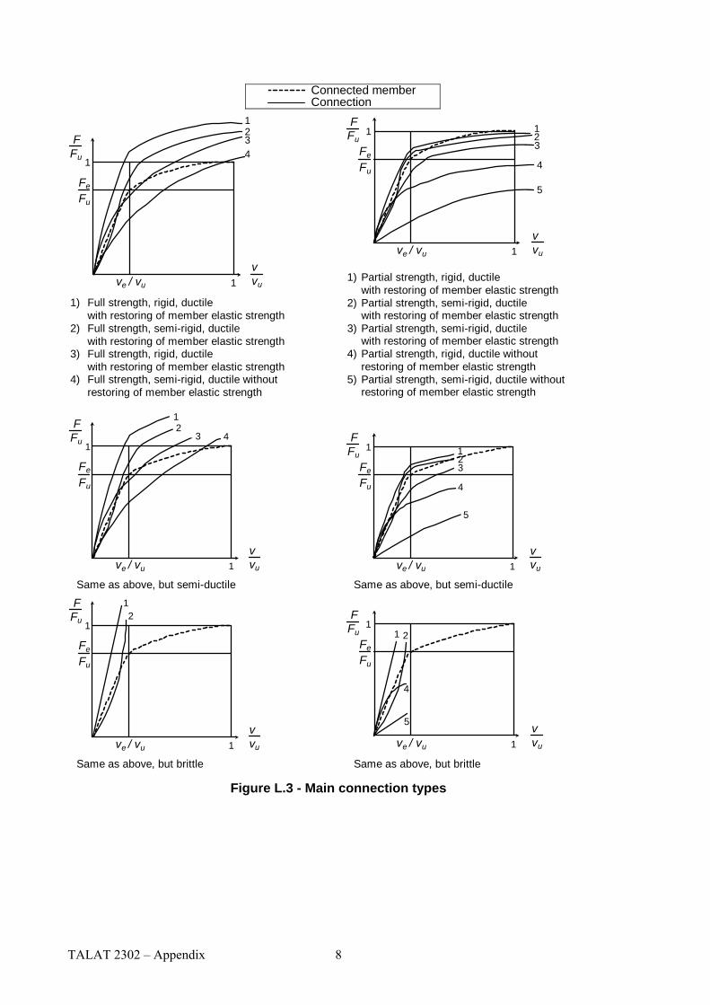
Connected member Connection
1
Fe
Fu
FFu
vvu
1
ve / vu 1
23
4
5
1
Fe
Fu
FFu
vvu
234
1
ve / vu 1 1) Full strength, rigid, ductile
with restoring of member elastic strength2) Full strength, semi-rigid, ductile
with restoring of member elastic strength3) Full strength, rigid, ductile
with restoring of member elastic strength4) Full strength, semi-rigid, ductile without
restoring of member elastic strength
1) Partial strength, rigid, ductilewith restoring of member elastic strength
2) Partial strength, semi-rigid, ductilewith restoring of member elastic strength
3) Partial strength, semi-rigid, ductilewith restoring of member elastic strength
4) Partial strength, rigid, ductile withoutrestoring of member elastic strength
5) Partial strength, semi-rigid, ductile withoutrestoring of member elastic strength
Fe
Fu
FFu
vvu
1
ve / vu 1
3 4
12
Fe
Fu
FFu
vvu
1
ve / vu 1
123
4
5
Same as above, but semi-ductile Same as above, but semi-ductile
Fe
Fu
FFu
vvu
1
ve / vu 1
12
Fe
Fu
FFu
vvu
1
ve / vu 1
1 2
4
5
Same as above, but brittle Same as above, but brittle
Figure L.3 - Main connection types
TALAT 2302 – Appendix 8

Table L.1 - General design requirements
Method of global analysis (see 5.2.1)
Type of connection which must be accounted for
Type of connection which may be ignored
ELASTIC
Semi-rigid connections (full or partial strength, ductile or non-ductile with or without restoring of member elastic strength) Partial strength connections (rigid or semi-rigid, ductile or non-ductile) without restoring of member elastic strength
Fully restoring connections
Rigid connections (full or partial strength, ductile or non-ductile) with restoring of member elastic strength
Partial strength connections (rigid, ductile or non-ductile) with restoring of member elastic strength
PLASTIC (rigid-plastic elastic-plastic inelastic-plastic)
Partial strength connections (rigid or semi-rigid ductile or non-ductile) without restoring of member elastic strength
Fully restoring connections
Partial strength, ductile connections (rigid or semi-rigid) with restoring of member elastic strength
Full strength connections HARDENING (rigid-hardening elastic-hardening generically inelastic)
Partially restoring connections Fully restoring connections
Table 8.6 - Slip factor of treated friction surfaces
Total joint thickness mm
Slip factor μ
12 ≤ Σt < 18 18 ≤ Σt < 24 24 ≤ Σt < 30
30 ≤ Σt
0,27 0,33 0,37 0,40
TALAT 2302 – Appendix 9
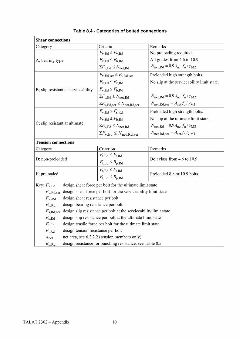
Table 8.4 - Categories of bolted connections
Shear connections Category Criteria Remarks
Rdv,Edv, FF
A; bearing type
≤
Rdb,Edv, FF ≤
Rdnet,Edv, NF ≤Σ
No preloading required. All grades from 4.6 to 10.9.
M2unetRdnet, /9,0 γfAN =
serRd,s,serEd,v, FF
B; slip resistant at serviceability
≤
Rdv,Edv, FF ≤
Rdb,Edv, FF ≤
Rdnet,Edv, NF ≤Σ
serRd,net,serEd,v, NF ≤Σ
Preloaded high strength bolts. No slip at the serviceability limit state.
M2unetRdnet, /9,0 γfAN =
M1onetserRd,net, /γfAN =
Rds,Edv, FF ≤ Preloaded high strength bolts.
Rdb,Edv, FF ≤ C; slip resistant at ultimate
Rdnet,Edv, NF ≤Σ
serRd,net,Edv, NF ≤Σ
No slip at the ultimate limit state.
M2unetRdnet, /9,0 γfAN =
M1onetserRd,net, /γfAN =
Tension connections Category Criterion Remarks
Rdt,Edt, FFD; non-preloaded
≤
Rdp,Edt, BF ≤ Bolt class from 4.6 to 10.9.
Rdt,Edt, FF ≤E; preloaded
Rdp,Edt, BF ≤ Preloaded 8.8 or 10.9 bolts.
Key: Fv,Ed design shear force per bolt for the ultimate limit state Fv,Ed,ser design shear force per bolt for the serviceability limit state Fv,Rd design shear resistance per bolt Fb,Rd design bearing resistance per bolt Fs,Rd,ser design slip resistance per bolt at the serviceability limit state Fs,Rd design slip resistance per bolt at the ultimate limit state Ft,Ed design tensile force per bolt for the ultimate limit state Ft,Rd design tension resistance per bolt Anet net area, see 6.2.2.2 (tension members only) Bp,Rd design resistance for punching resistance, see Table 8.5.
TALAT 2302 – Appendix 10

Fv,Ed
VEd MEdFv,Ed
p
p
p
pVEd
Fv,Ed
Fv,Ed
Fh,Ed
0,5 Fh,Ed
VEd MEdFh,Ed
0,5 Fh,Ed
VEd
5
p
p
p
p
Fh,Ed =MEd
5 (a) Elastic load distribution Distribution proportional to distance from centre of rotation
2Ed
2Ed
Edv, 55⎟⎠⎞
⎜⎝⎛+⎟⎟
⎠
⎞⎜⎜⎝
⎛=
Vp
MF (8.7)
(b) Plastic load distribution Possible plastic distribution with one fastener resisting VEd and four resisting MEd
pM
F6
EdEdv, = (8.8)
Figure 8.7 - Example of distribution of loads between fasteners (five bolts)
N Ed
N Ed
1
2
4
3
N Ed
N Ed
1 small tension force, 2 large shear force, 3 small shear force and 4 large tension force
Figure 8.5 - Block tearing
TALAT 2302 – Appendix 11
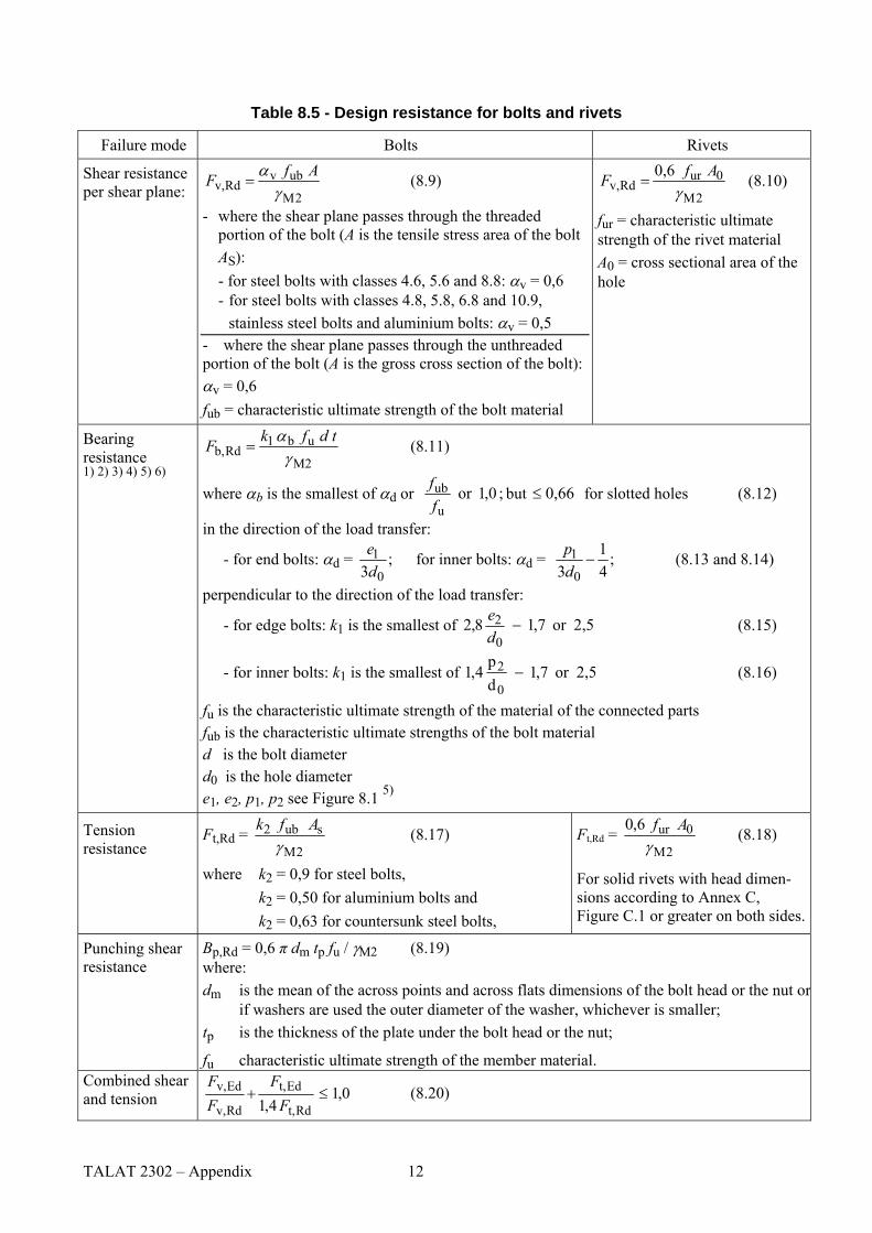
Table 8.5 - Design resistance for bolts and rivets
Failure mode Bolts Rivets
2M
ubvRdv,
γ
α AfF = (8.9)
- where the shear plane passes through the threaded portion of the bolt (A is the tensile stress area of the bolt AS):
- for steel bolts with classes 4.6, 5.6 and 8.8: αv = 0,6 - for steel bolts with classes 4.8, 5.8, 6.8 and 10.9,
stainless steel bolts and aluminium bolts: αv = 0,5 - where the shear plane passes through the unthreaded portion of the bolt (A is the gross cross section of the bolt): αv = 0,6 fub = characteristic ultimate strength of the bolt material
2M
0urRdv,
0,6γ
AfF = (8.10)
fur = characteristic ultimate strength of the rivet material A0 = cross sectional area of the hole
Shear resistance per shear plane:
M2
ub1Rdb,
γα d tfkF = (8.11) Bearing
resistance 1) 2) 3) 4) 5) 6)
where αb is the smallest of αd or ; 0,1 or u
ubff but 0,66≤ for slotted holes (8.12)
in the direction of the load transfer:
- for end bolts: αd = ;3 0
1de for inner bolts: αd = ;
41
3
0
1 −dp (8.13 and 8.14)
perpendicular to the direction of the load transfer:
- for edge bolts: k1 is the smallest of 2,5or 7,1 8,20
2 −de (8.15)
- for inner bolts: k1 is the smallest of 2,5or 7,1 dp
4,10
2 − (8.16)
fu is the characteristic ultimate strength of the material of the connected parts fub is the characteristic ultimate strengths of the bolt material d is the bolt diameter
d0 is the hole diameter e1, e2, p1, p2 see Figure 8.1 5)
Ft,Rd = 2M
sub2γ
Afk (8.17) Tension resistance
where k2 = 0,9 for steel bolts, k2 = 0,50 for aluminium bolts and k2 = 0,63 for countersunk steel bolts,
Ft,Rd = 2M
0ur6,0γ
Af (8.18)
For solid rivets with head dimen-sions according to Annex C, Figure C.1 or greater on both sides.
Punching shear resistance
BBp,Rd = 0,6 π dm tp fu / γM2 (8.19) where: dm is the mean of the across points and across flats dimensions of the bolt head or the nut or
if washers are used the outer diameter of the washer, whichever is smaller; tp is the thickness of the plate under the bolt head or the nut;
fu characteristic ultimate strength of the member material. Combined shear and tension 0,1
4,1 Rdt,
Edt,
Rdv,
Edv, ≤+F
FFF
(8.20)
TALAT 2302 – Appendix 12

1) The bearing resistance Fb,Rd for bolts - in oversized holes according to prEN 1090-3 is 0,8 times the bearing resistance for bolts in normal holes, - in short slotted holes, where the longitudinal axis of the slotted hole is perpendicular to the direction of the force transfer and the length of the slotted hole is not more than 1,5 times the diameter of the round part of the hole, is 0,80 times the bearing resistance for bolts in round, normal holes. - in long slotted holes, where the longitudinal axis of the slotted hole is perpendicular to the direction of the force transfer and the length of the slotted hole is between 1,5 times the hole diameter and 2,5 times the hole diameter of the round part of the hole, is 0,65 times the bearing resistance for bolts in round, normal holes.
2) For countersunk bolts: - the bearing resistance Fb,Rd should be based on a plate thickness t equal to the thickness of the connected
plate minus half the depth of the countersinking, 3) In addition to bearing resistance, the net section resistance needs to be checked 4) If the load on a bolt is not parallel to the edge, the bearing resistance may be verified separately for the bolt
load components parallel and normal to the end. 5) Aluminium bolts should not be used in connections with slotted holes. 6) For slotted holes replace d0 by (d + 1 mm), e1 by (e3 + d/2), e2 by (e4 + d/2), p1 by (p3 + d) and p2 by (p4 +
d) where p3, p4, e3 and e4 are found in Figure 8.4.
(c)
e1 p1p1
(b)
e1 p1
(a)
e1
e 2
d o
A1
(a) One bolt, (b) two bolts and (c) three bolts
Figure 8.6 - Connections of angles
Table 8.3 - Reduction factors ß2 and ß3
Pitch p1 ≤ 2,5 d0 ≥ 5,0 d0β2 for 2 bolts 0,4 0,7
β3 for 3 bolts or more 0,5 0,7
Figure 8.11 - Single lap joint with one row of bolts
TALAT 2302 – Appendix 13
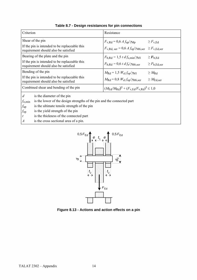
Table 8.7 - Design resistances for pin connections
Criterion Resistance
Shear of the pin If the pin is intended to be replaceable this requirement should also be satisfied
Fv,Rd = 0,6 A fup/γMp
Fv,Rd, ser = 0,6 A fop/γM6,ser
≥ Fv,Ed
≥ Fv,Ed,ser
Bearing of the plate and the pin If the pin is intended to be replaceable this requirement should also be satisfied
Fb,Rd = 1,5 t d fo,min/γM1
Fb,Rd = 0,6 t d fo/γM6,ser
≥ Fb,Ed
≥ Fb,Ed,ser
Bending of the pin If the pin is intended to be replaceable this requirement should also be satisfied
MRd = 1,5 Wel fop/γM1
MRd = 0,8 Wel fop/γM6,ser
≥ MRd
≥ MEd,ser
Combined shear and bending of the pin (MEd/MRd)² + (Fv,Ed/Fv,Rd)² ≤ 1,0
d is the diameter of the pin fo,min is the lower of the design strengths of the pin and the connected part fup is the ultimate tensile strength of the pin fop is the yield strength of the pin t is the thickness of the connected part A is the cross sectional area of a pin.
d 0d
0,5 FEd 0,5 FEd
FEd
t2
et1e
t2
Figure 8.13 - Actions and action effects on a pin
TALAT 2302 – Appendix 14
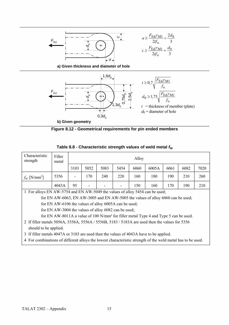
a
c
d 0
FEd
32
20
o
M1Ed dtf
Fa +≥
γ
320
o
M1Ed dtf
Fc +≥
γ
a) Given thickness and diameter of hole
1,6d0
2,5d
0
0,75
d 0
0,3d0
1,3d0
d 0FEd
b) Given geometry
o
M1Ed7,0f
Ft
γ≥
o
M1Ed0 75,1
fF
dγ
≥
t = thickness of member (plate) d0 = diameter of hole
Figure 8.12 - Geometrical requirements for pin ended members
Table 8.8 - Characteristic strength values of weld metal fw
Characteristic strength
Filler metal
Alloy
3103 5052 5083 5454 6060 6005A 6061 6082 7020
fw [N/mm2] 5356 - 170 240 220 160 180 190 210 260
4043A 95 - - - 150 160 170 190 210 1 For alloys EN AW-5754 and EN AW-5049 the values of alloy 5454 can be used; for EN AW-6063, EN AW-3005 and EN AW-5005 the values of alloy 6060 can be used; for EN AW-6106 the values of alloy 6005A can be used; for EN AW-3004 the values of alloy 6082 can be used; for EN AW-8011A a value of 100 N/mm² for filler metal Type 4 and Type 5 can be used. 2 If filler metals 5056A, 5356A, 5556A / 5556B, 5183 / 5183A are used then the values for 5356 should to be applied. 3 If filler metals 4047A or 3103 are used then the values of 4043A have to be applied. 4 For combinations of different alloys the lowest characteristic strength of the weld metal has to be used.
TALAT 2302 – Appendix 15
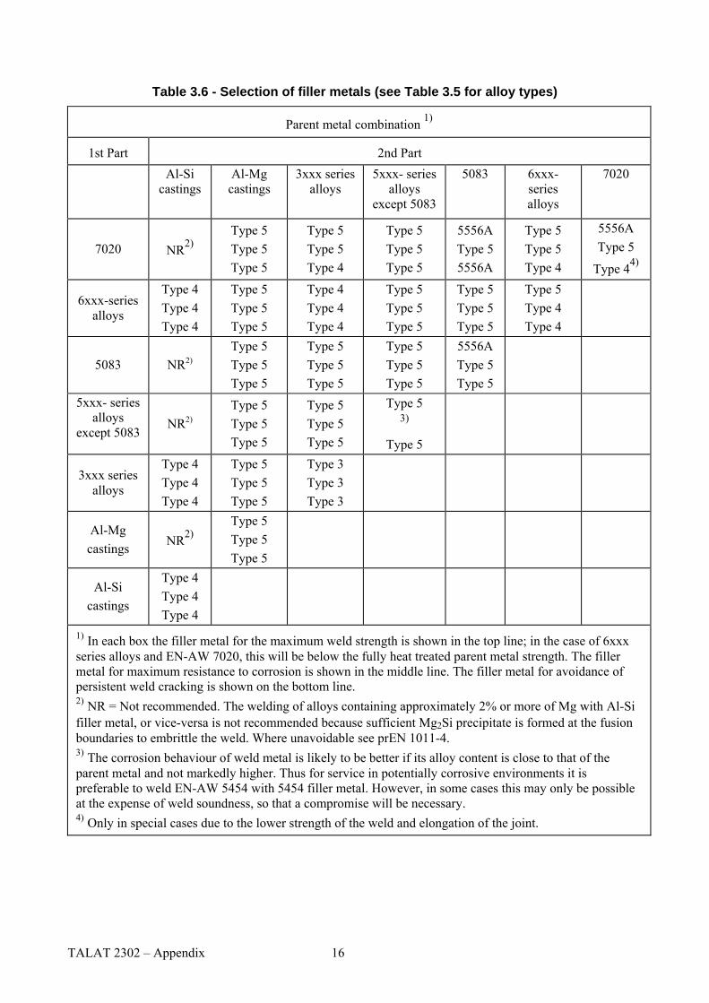
Table 3.6 - Selection of filler metals (see Table 3.5 for alloy types)
Parent metal combination 1)
1st Part 2nd Part Al-Si
castings Al-Mg castings
3xxx series alloys
5xxx- series alloys
except 5083
5083 6xxx-series alloys
7020
7020 NR2)Type 5 Type 5 Type 5
Type 5 Type 5 Type 4
Type 5 Type 5 Type 5
5556A Type 5 5556A
Type 5 Type 5 Type 4
5556A Type 5
Type 44)
6xxx-series alloys
Type 4 Type 4 Type 4
Type 5 Type 5 Type 5
Type 4 Type 4 Type 4
Type 5 Type 5 Type 5
Type 5 Type 5 Type 5
Type 5 Type 4 Type 4
5083 NR2)Type 5 Type 5 Type 5
Type 5 Type 5 Type 5
Type 5 Type 5 Type 5
5556A Type 5 Type 5
5xxx- series alloys
except 5083 NR2)
Type 5 Type 5 Type 5
Type 5 Type 5 Type 5
Type 5 3)
Type 5
3xxx series alloys
Type 4 Type 4 Type 4
Type 5 Type 5 Type 5
Type 3 Type 3 Type 3
Al-Mg castings NR2)
Type 5 Type 5 Type 5
Al-Si castings
Type 4 Type 4 Type 4
1) In each box the filler metal for the maximum weld strength is shown in the top line; in the case of 6xxx series alloys and EN-AW 7020, this will be below the fully heat treated parent metal strength. The filler metal for maximum resistance to corrosion is shown in the middle line. The filler metal for avoidance of persistent weld cracking is shown on the bottom line. 2) NR = Not recommended. The welding of alloys containing approximately 2% or more of Mg with Al-Si filler metal, or vice-versa is not recommended because sufficient Mg2Si precipitate is formed at the fusion boundaries to embrittle the weld. Where unavoidable see prEN 1011-4. 3) The corrosion behaviour of weld metal is likely to be better if its alloy content is close to that of the parent metal and not markedly higher. Thus for service in potentially corrosive environments it is preferable to weld EN-AW 5454 with 5454 filler metal. However, in some cases this may only be possible at the expense of weld soundness, so that a compromise will be necessary. 4) Only in special cases due to the lower strength of the weld and elongation of the joint.
TALAT 2302 – Appendix 16
F, σ
bt
F, σ
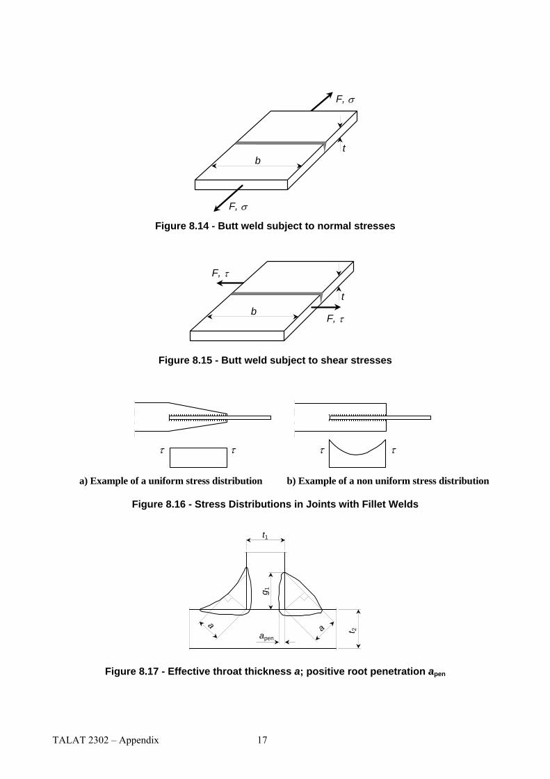
Figure 8.14 - Butt weld subject to normal stresses
F, τb
t
F, τ
Figure 8.15 - Butt weld subject to shear stresses
ττττ
a) Example of a uniform stress distribution b) Example of a non uniform stress distribution
Figure 8.16 - Stress Distributions in Joints with Fillet Welds
aapen
g 1
a t 2
t1
Figure 8.17 - Effective throat thickness a; positive root penetration apen
TALAT 2302 – Appendix 17

τ ⊥
σ ⊥⊥
F/2
t
τ ⊥
σ ⊥
F/2
F
Figure 8.19 - Double fillet welded joint loaded perpendicularly to the weld axis
t
F
a
h
F
Figure 8.20 - Double fillet welded joint loaded parallel to the weld axis
R
te
T T
t
T
t
F
F
t
te
The line F = HAZ in the fusion boundary; the line T = HAZ in toe of the weld, full cross section,
te = effective throat section, R = root bead
Figure 8.21 - Failure planes in HAZ adjacent to a weld
TALAT 2302 – Appendix 18

b haz
bhazb haz
bhaz
bhaz
b haz
bhaz
b haz
bhaz
b haz
bhazbhaz
b haz
bhaz
bhaz
bhaz
b haz
*)
b haz
bhazbhaz
*) If this distance is less than assume that the HAZ extends to the full width of outstand, see 6.1.6.3(7) haz3b
Figure 6.6 - The extent of heat-affected zones (HAZ)
Table M.1 - Characteristic shear strength values of adhesives
Adhesive types fv,adh N/mm2
1- component, heat cured, modified epoxide 2- components, cold cured, modified epoxide 2- components, cold cured, modified acrylic
35 25 20
ISO 11003-1:2001 Adhesives -- Determination of shear behaviour of structural adhesives -- Part 1:
Torsion test method using butt-bonded hollow cylinders
ISO 11003-2:2001 Adhesives -- Determination of shear behaviour of structural adhesives -- Part 2: Tensile test method using thick adherents
TALAT 2302 – Appendix 19


![Dreptul Afacerilor În Uniunea Europeana 2302[1]](https://img.pdfslide.tips/doc/110x75/55cf8ef9550346703b97989c/dreptul-afacerilor-in-uniunea-europeana-23021.jpg)