Embed Size (px)
Citation preview

10” Jobsite Table Saw with Foldable Stand
240-3605
CAUTION: To reduce the risk of injury, user must read and understand
operator’s manual. save these instructions for future reference. Customer Service Toll-Free Helpline 1-877-684-8912 (Monday - Friday 8am - 6pm EST.)

Safety Symbols…………………………………………………………………………………………………………………………..Page 3
Safety Instructions……………………………………………………………………………….………………………………………Page 4
Unpacking…………………………………………………………………………………………………….……………………...…..Page 9
Overview / Specifications…………………………………………………………………………………......………………...…….Page 10
Assembly…………………………………………………………………………………………………………………........……….Page 13
Installation………………………………………………………………………………………………….................…….....…….. Page 30
Operation……………………………………………………………………………………………….....…….................………… Page 32
Maintenance.........................................................................................................................................................................Page 43
Troubleshooting...................................................................................................................................................................Page 45
Replacement Parts..............................................................................................................................................................Page 47
Warranty..............................................................................................................................................................................Page 48
TABLE OF CONTENTS
_ 2 _
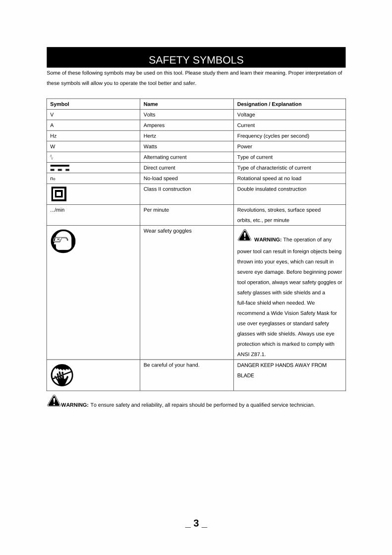
Some of these following symbols may be used on this tool. Please study them and learn their meaning. Proper interpretation of
these symbols will allow you to operate the tool better and safer.
Symbol Name Designation / Explanation
V Volts Voltage
A Amperes Current
Hz Hertz Frequency (cycles per second)
W Watts Power
∿ Alternating current Type of current
Direct current Type of characteristic of current
no No-load speed Rotational speed at no load
Class II construction Double insulated construction
.../min Per minute Revolutions, strokes, surface speed
orbits, etc., per minute
Wear safety goggles
WARNING: The operation of any
power tool can result in foreign objects being
thrown into your eyes, which can result in
severe eye damage. Before beginning power
tool operation, always wear safety goggles or
safety glasses with side shields and a
full-face shield when needed. We
recommend a Wide Vision Safety Mask for
use over eyeglasses or standard safety
glasses with side shields. Always use eye
protection which is marked to comply with
ANSI Z87.1.
Be careful of your hand. DANGER KEEP HANDS AWAY FROM
BLADE
WARNING: To ensure safety and reliability, all repairs should be performed by a qualified service technician.
SAFETY SYMBOLS
_ 3 _
The purpose of safety symbols is to attract your attention to possible dangers. Please pay careful attention to the safety symbols
and the definition. The symbol warnings do not, by themselves, eliminate any danger. The instructions and warnings they give
are no substitutes for proper accident prevention
measures.
WARNING: Be sure to read and understand all safety instructions in this manual, including all safety alert symbols such as
“DANGER,” ”WARNING,” and “CAUTION” before using this tool. Failure to following all instructions listed below may result in
electric shock, fire, and/or serious personal injury.
SYMBOL MEANING
SAFETY ALERT SYMBOL: Indicates DANGER, WARNING, OR CAUTION. May be used in conjunction with other
symbols or pictographs.
DANGER: Indicates an imminently hazardous situation, which, if not avoided, will result in death or serious injury.
WARNING: Indicates a potentially hazardous situation, which, if not avoided, could result in death or serious injury.
CAUTION: Indicates a potentially hazardous situation, which, if not avoided, could result in minor or moderate injury.
NOTICE: (Without Safety Alert Symbol) Indicates a situation that may result in property damage.
SAVE THESE INSTRUCTIONS!
SAFETY INSTRUCTIONS
_ 4 _
WARNING: Read and understand all instructions. Failure to follow all instructions listed below, may result in electric
shock, fire and/or serious personal injury.
GENERAL SAFETY RULES PROPOSITION 65 WARNING: Some dust created by using power tools contain chemicals known to the state of California to
cause cancer, birth defects or other reproductive harm. Some examples of these chemicals are:
• Lead from lead-based paints.
• Crystalline silica from bricks and cement and other masonry products.
• Arsenic and chromium from chemically-treated lumber.
Your risk from these exposures vary, depending on how often you do this type of work. To reduce your exposure to these
chemicals: work in a well ventilated area and work with approved safety equipment. Always wear OSHA/NIOSH approved,
properly fitting face mask or respirator when using such tools.
CAUTION: Always follow proper operating procedures as defined in this manual — even if you are familiar with use of this
or similar tools. Remember that being careless for even a fraction of a second can result in severe personal injury.
WARNING: THIS PRODUCT CONTAINS LEAD. A CHEMICAL KNOWN TO THE STATE OF CALIFORNIA TO CAUSE
CANCER AND BIRTH DEFECTS OR OTHER REPRODUCTIVE HARM.
WASH HANDS AFTER HANDLING.
• KNOW YOUR POWER TOOL. Read the operator’s manual carefully. Learn the saw’s applications and limitations as well as the
specific potential hazards related to this tool.
• GUARD AGAINST ELECTRICAL SHOCK BY PREVENTING BODY CONTACT WITH GROUNDED SURFACES. For
example, pipes, radiators, ranges, refrigerator enclosures.
• KEEP GUARDS IN PLACE and in good working order.
• REMOVE ADJUSTING KEYS AND WRENCHES. Form habit of checking to see that keys and adjusting wrenches are
removed from tool before turning it on.
• KEEP WORK AREA CLEAN. Cluttered areas and benches invite accidents. DO NOT leave tools or pieces of wood on the saw
while it is in operation.
• DO NOT USE IN DANGEROUS ENVIRONMENTS. Do not use power tools in damp or wet locations or expose to rain. Keep
the work area well lit.
• KEEP CHILDREN AND VISITORS AWAY. All visitors should wear safety glasses and be kept a safe distance from work area.
Do not let visitors contact tool or extension cord while operating.
• MAKE WORKSHOP CHILDPROOF with padlocks and master switches, or by removing starter keys.
• DON’T FORCE TOOL. It will do the job better and safer at the feed rate for which it was designed.
• USE RIGHT TOOL. Don’t force the tool or attachment to do a job it was not designed for. Don’t use it for a purpose not
intended.
• USE THE PROPER EXTENSION CORD. Make sure your extension cord is in good condition. Use only a cord heavy enough to
carry the current your product will draw. An undersized cord will cause a drop in line voltage resulting in loss of power and
overheating. loss of power and overheating. A wire gauge size (A.W.G.) of at least 14 is recommended for an extension cord 25
feet or less in length. If in doubt, use the next heavier gauge. The smaller the gauge number, the heavier the cord.
SAFETY INSTRUCTIONS
_ 5 _
• DRESS PROPERLY. Do not wear loose clothing, gloves, neckties, or jewelry. They can get caught and draw you into moving
parts. Rubber gloves and nonskid footwear are recommended when working outdoors. Also wear protective hair covering to
contain long hair.
• ALWAYS wear safety goggles that comply with United States ANSI Z87.1 and a face shield or dust mask if operation is dusty.
Everyday eyeglasses have only impact-resistant lenses, they are NOT safety glasses.
• SECURE WORK. Use a clamps or vice to hold workpiece when practical. It’s safer than using your hand and frees both hands
to operate tool.
• DON’T OVERREACH. Keep proper footing and balance at all times.
• MAINTAIN TOOLS WITH CARE. Keep tools sharp and clean for better and safer performance. Follow instructions for
lubricating and changing accessories.
• DISCONNECT TOOLS. When not in use, before servicing, or when changing attachments, blades, bits, cutters, etc., all tools
should be disconnected.
• AVOID ACCIDENTAL STARTING. Be sure switch is off when plugging in any tool.
• USE RECOMMENDED ACCESSORIES. Consult the operator’s manual for recommended accessories. The use of improper
accessories may risk injury.
• NEVER STAND ON TOOL. Serious injury could occur if the tool is tipped or if the cutting tool is unintentionally contacted.
• CHECK DAMAGED PARTS. Before further use of the tool, a guard or other part that is damaged should be carefully
checked to determine that it will operate properly and perform its intended function. Check for alignment of moving parts, binding
of moving parts, breakage of parts, mounting and any other conditions that may affect its operation. A guard or other part that is
damaged must be properly repaired or replaced by an authorized service center to avoid risk of personal injury.
• USE THE RIGHT DIRECTION OF FEED. Feed workpiece into a blade or cutter against the direction of rotation of blade or
cutter only.
• NEVER LEAVE TOOL RUNNING UNATTENDED. TURN THE POWER OFF. Don’t leave tool until it comes to a complete stop.
• PROTECT YOUR LUNGS. Wear a face or dust mask if the cutting operation is dusty.
• PROTECT YOUR HEARING. Wear ear plugs or muffs during extended periods of operation.
• DO NOT ABUSE CORD. Never yank cord to disconnect from receptacle. Keep cord away from heat, oil, and sharp edges.
• WHEN OPERATING A POWER TOOL OUTSIDE, USE AN OUTDOOR EXTENSION CORD MARKED “W-A” OR “W”. These
cords are rated for outdoor use and reduce the risk of electric shock.
• ALWAYS KEEP THE BLADE GUARD AND SPREADER (RIVING KNIFE) IN PLACE and in working order.
• KEEP BLADES CLEAN, SHARP, AND WITH SUFFICIENT SET. Sharp blades minimize stalling and kickback.
• KEEP HANDS AWAY FROM CUTTING AREA. Keep hands away from blades. Do not reach underneath work or around or
over the blade while blade is rotating. Do not attempt to remove cut material when blade is moving.
• BLADE COASTS AFTER BEING TURNED OFF.
• NEVER USE IN AN EXPLOSIVE ATMOSPHERE. Normal sparking of the motor could ignite fumes.
• INSPECT TOOL CORDS PERIODICALLY. If damaged, have repaired by a qualified service technician at an authorized service
facility. The conductor with insulation having an outer surface that is green with or without yellow stripes is the
equipment-grounding conductor. If repair or replacement of the electric cord or plug is necessary, do not connect the
equipment-grounding conductor to a live terminal. Repair or replace a damaged or worn cord immediately. Stay constantly aware
of cord location and keep it well away from the rotating blade.
• INSPECT EXTENSION CORDS PERIODICALLY and replace if damaged.
• GROUND ALL TOOLS. If tool is equipped with three-prong plug, it should be plugged into a three-hole electrical receptacle.
• CHECK WITH A QUALIFIED ELECTRICIAN or service personnel, if the grounding instructions are not completely understood,
SAFETY INSTRUCTIONS
_ 6 _
or if in doubt as to whether the tool is properly grounded.
• USE ONLY CORRECT ELECTRICAL DEVICES: 3-wire extension cords that have 3-prong grounding plugs and 3-hole
receptacles that accept the tool's plug.
• DO NOT MODIFY the plug provided. If it will not fit the outlet, have the proper outlet installed by a qualified electrician.
• KEEP TOOL DRY, CLEAN, AND FREE FROM OIL AND GREASE. Always use a clean cloth when cleaning. Never use brake
fluids, gasoline, petroleum-based products, or any solvents to clean tool.
• STAY ALERT AND EXERCISE CONTROL. Watch what you are doing and use common sense. Do not operate tool when you
are tired. Do not rush.
• DO NOT USE TOOL IF SWITCH DOES NOT TURN IT ON AND OFF. Have defective switches replaced by an authorized
service center.
• USE ONLY CORRECT BLADES. Do NOT use blades with incorrect size holes. Never use blade washers or blade bolts that
are defective or incorrect. The maximum blade capacity of your saw is 10 in.
• BEFORE MAKING A CUT, BE SURE ALL ADJUSTMENTS ARE SECURE.
• BE SURE BLADE PATH IS FREE OF NAILS. Inspect for and remove all nails from lumber before cutting.
• NEVER TOUCH BLADE or other moving parts during use.
• NEVER START A TOOL WHEN ANY ROTATING COMPONENT IS IN CONTACT WITH THE WORKPIECE.
• DO NOT OPERATE A TOOL WHILE UNDER THE INFLUENCE OF DRUGS, ALCOHOL, OR ANY MEDICATION.
• WHEN SERVICING use only identical replacement parts. Use of any other parts may create a hazard or cause product
damage.
• USE ONLY RECOMMENDED ACCESSORIES listed in this manual or addendums. Use of accessories that are not listed may
cause the risk of personal injury. Instructions for safe use of accessories are included with the accessory.
• DOUBLE CHECK ALL SETUPS. Make sure blade is tight and not making contact with saw or workpiece before connecting to
power supply.
SPECIFIC SAFETY RULES • FIRMLY BOLT THE SAW TO A WORK BENCH OR LEG STAND at approximately hip height.
• NEVER OPERATE THE SAW ON THE FLOOR.
• KEEP GUARDS IN PLACE and in good working order.
• GUARD AGAINST KICKBACK. Kickback occurs when the blade stalls rapidly and workpiece is driven back towards the
operator. It can pull your hand into the blade resulting in serious personal injury. Stay out of blade path and turn switch off
immediately if blade binds or stalls.
• USE RIP FENCE. Always use a fence or straight edge guide when ripping.
• SUPPORT LARGE PANELS. To minimize risk of blade pinching and kickback, always support large panels.
• REMOVE ALL FENCES AND AUXILIARY TABLES before transporting saw. Failure to do so can result in an accident causing
possible serious personal injury.
• DON’T OVERREACH. Keep proper footing and balance at all times.
• NEVER place arms or hands in line with the path of the cutting blade.
• ALWAYS USE BLADE GUARD, RIVING KNIFE, AND ANTI-KICKBACK PAWLS on all through cut operations. Through cut
operations are those in which the blade cuts completely through the workpiece as in ripping or cross cutting. Keep the blade
guard down, the anti-kickback pawls down, and the spreader in place over the blade.
SAFETY INSTRUCTIONS
_ 7 _
• ALWAYS SECURE WORK firmly against the rip fence or miter gauge. NEVER use the rip fence during the same operation as
the miter gauge.
• ALWAYS USE A PUSH STICK. A push stick is a device used to push a workpiece through the blade instead of using your
hands. Size and shape can vary but the push stick must always be narrower than the workpiece to prevent the push stick from
contacting the saw blade. When ripping narrow stock, always use a push stick, so your hand does not come close to the saw
blade. Use a featherboard and push blocks for non-through cuts.
• NEVER perform any operation “freehand” which means using only your hands to support or guide the workpiece. Always use
either the rip fence or miter fence to position and guide the work.
• NEVER stand or have any part of your body in line with the path of the saw blade.
• NEVER reach behind, over, or within three inches of the blade or cutter with either hand for any reason.
• MOVE THE RIP FENCE out of the way when cross cutting.
• DO NOT USE THE MITER GAUGE AND RIP FENCE during the same operation.
• NEVER attempt to free a stalled saw blade without first turning the saw OFF and disconnecting the saw from the power source.
• PROVIDE ADEQUATE SUPPORT to the rear and sides of the saw table for wide or long work pieces.
• AVOID KICKBACKS (work thrown back toward you) by:
a) Keeping blade sharp.
b) Keeping rip fence parallel to the saw blade.
c) Keeping spreader, anti-kickback pawls, and blade guard in place and operating.
d) Not releasing the work before it is pushed all the way past the saw blade using a push stick.
e) Not ripping work that is twisted or warped or does not have a straight edge to guide along the fence.
• IF THE POWER SUPPLY CORD IS DAMAGED, it must be replaced only by the manufacturer or by an authorized service
center to avoid risk.
• AVOID AWKWARD OPERATIONS AND HAND POSITIONS where a sudden slip could cause your hand to move into the
cutting tool.
• USE ONLY RECOMMENDED ACCESSORIES listed in this manual or addendums. Use of accessories that are not listed may
cause the risk of personal injury. Instructions for safe use of accessories are included with the accessory.
• MAKE SURE THE WORK AREA HAS AMPLE LIGHTING to see the work and that no obstructions will interfere with safe
operation BEFORE performing any work using the table saw.
• ALWAYS TURN OFF SAW before disconnecting it, to avoid accidental starting when reconnecting to power supply.
• SAVE THESE INSTRUCTIONS. Refer to them frequently and use to instruct other users. If you loan someone this tool, loan
them these instructions also.
THINK SAFETY
Safety is a combination of operator common sense and alertness at all times when the saw is being used.
CAUTION: Follow safety instructions that appear on the front of your saw.
SAFETY INSTRUCTIONS
_ 8 _
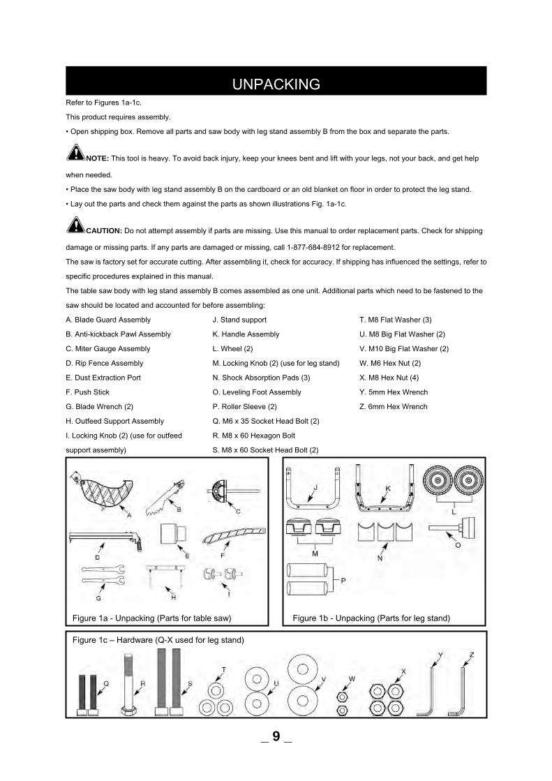
Refer to Figures 1a-1c.
This product requires assembly.
• Open shipping box. Remove all parts and saw body with leg stand assembly B from the box and separate the parts.
NOTE: This tool is heavy. To avoid back injury, keep your knees bent and lift with your legs, not your back, and get help
when needed.
• Place the saw body with leg stand assembly B on the cardboard or an old blanket on floor in order to protect the leg stand.
• Lay out the parts and check them against the parts as shown illustrations Fig. 1a-1c.
CAUTION: Do not attempt assembly if parts are missing. Use this manual to order replacement parts. Check for shipping
damage or missing parts. If any parts are damaged or missing, call 1-877-684-8912 for replacement.
The saw is factory set for accurate cutting. After assembling it, check for accuracy. If shipping has influenced the settings, refer to
specific procedures explained in this manual.
The table saw body with leg stand assembly B comes assembled as one unit. Additional parts which need to be fastened to the
saw should be located and accounted for before assembling:
A. Blade Guard Assembly
B. Anti-kickback Pawl Assembly
C. Miter Gauge Assembly
D. Rip Fence Assembly
E. Dust Extraction Port
F. Push Stick
G. Blade Wrench (2)
H. Outfeed Support Assembly
I. Locking Knob (2) (use for outfeed
support assembly)
J. Stand support
K. Handle Assembly
L. Wheel (2)
M. Locking Knob (2) (use for leg stand)
N. Shock Absorption Pads (3)
O. Leveling Foot Assembly
P. Roller Sleeve (2)
Q. M6 x 35 Socket Head Bolt (2)
R. M8 x 60 Hexagon Bolt
S. M8 x 60 Socket Head Bolt (2)
T. M8 Flat Washer (3)
U. M8 Big Flat Washer (2)
V. M10 Big Flat Washer (2)
W. M6 Hex Nut (2)
X. M8 Hex Nut (4)
Y. 5mm Hex Wrench
Z. 6mm Hex Wrench
UNPACKING
_ 9 _
Figure 1a - Unpacking (Parts for table saw) Figure 1b - Unpacking (Parts for leg stand)
Figure 1c – Hardware (Q-X used for leg stand)
KNOW YOUR TABLE SAW Refer to Figure 2.
The safe use of this product requires an understanding of the information on the tool and in this operator’s manual as well as a
knowledge of the project you are attempting. Before use of this product, familiarize yourself with all operating features and safety
rules.
ANTI-KICKBACK PAWLS: Kickback is a hazard in which the workpiece is thrown back toward the operator. The teeth on the
anti-kickback pawls point away from the workpiece. If the workpiece should be pulled back toward the operator, the teeth dig into
the wood to help prevent or reduce the possibility of kickback.
BEVEL SCALE: The easy-to-read scale on the front of the cabinet shows the exact blade angle.
BLADE: For maximum performance, it is recommended that you use the 40-tooth, 10 in. carbide tipped combination blade
provided with your saw. The blade is raised and lowered with the height/bevel adjusting handwheel. Bevel angles are locked with
the bevel locking lever.
WARNING: Do not use blades rated less than the speed of this tool. Failure to heed this warning could result in personal
injury.
BLADE GUARD: Always keep the guard down over the blade for through-sawing cuts.
BEVEL LOCKING LEVER: This lever under the worktable surface on the front of the cabinet, locks the angle setting of the blade.
HEIGHT/BEVEL ADJUSTING HANDWHEEL: Located on the front of the cabinet, this handwheel is used to lower
and raise the blade for adjustments or blade replacement. The handwheel also makes the adjustment for bevel angles easy.
RIP FENCE LOCKING LEVER: The lever on the front of the rip fence releases the rip fence or locks it in place.
EXTENSION TABLE LOCKING LEVER: The lever under worktable surface releases the extension table or locks it
in place.
OUTFEED SUPPORT: The outfeed support at the back of the tool gives the operator additional support when cutting long
workpieces.
MITER GAUGE: The miter gauge aligns the wood for a cross cut. The easy-to-read indicator shows the exact angle for a miter
cut, with positive stops at 0°, 22.5° and 45°.
MITER GAUGE GROOVES: The miter gauge rides in these grooves on either side of the blade.
RAIL: Front rail provides support for the rip fence.
RIP FENCE: A sturdy metal fence guides the workpiece and is secured with the locking lever. Grooves run along the top and
sides of the rip fence for use with optional clamps and accessories.
SCALE: Located on the front rail, the easy-to-read scale provides precise measurements for rip cuts.
RIVING KNIFE: A metal piece of the blade guard assembly, slightly thinner than the saw blade, which helps keep the kerf open
and prevent kickback.
SWITCH ASSEMBLY: This saw has an easy access power switch. To lock the switch in the OFF position, remove the yellow
switch key from the switch. Place the key in a location that is inaccessible to children and others not qualified to use the tool.
OVERVIEW / SPECIFICATIONS
_ 10 _
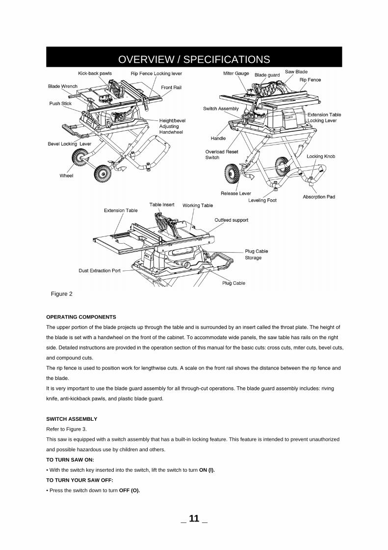
OPERATING COMPONENTS
The upper portion of the blade projects up through the table and is surrounded by an insert called the throat plate. The height of
the blade is set with a handwheel on the front of the cabinet. To accommodate wide panels, the saw table has rails on the right
side. Detailed instructions are provided in the operation section of this manual for the basic cuts: cross cuts, miter cuts, bevel cuts,
and compound cuts.
The rip fence is used to position work for lengthwise cuts. A scale on the front rail shows the distance between the rip fence and
the blade.
It is very important to use the blade guard assembly for all through-cut operations. The blade guard assembly includes: riving
knife, anti-kickback pawls, and plastic blade guard.
SWITCH ASSEMBLY
Refer to Figure 3.
This saw is equipped with a switch assembly that has a built-in locking feature. This feature is intended to prevent unauthorized
and possible hazardous use by children and others.
TO TURN SAW ON:
• With the switch key inserted into the switch, lift the switch to turn ON (l).
TO TURN YOUR SAW OFF:
• Press the switch down to turn OFF (O).
OVERVIEW / SPECIFICATIONS
Figure 2
_ 11 _
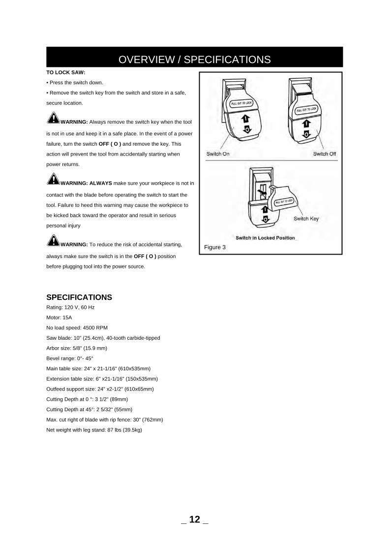
TO LOCK SAW:
• Press the switch down.
• Remove the switch key from the switch and store in a safe,
secure location.
WARNING: Always remove the switch key when the tool
is not in use and keep it in a safe place. In the event of a power
failure, turn the switch OFF ( O ) and remove the key. This
action will prevent the tool from accidentally starting when
power returns.
WARNING: ALWAYS make sure your workpiece is not in
contact with the blade before operating the switch to start the
tool. Failure to heed this warning may cause the workpiece to
be kicked back toward the operator and result in serious
personal injury
WARNING: To reduce the risk of accidental starting,
always make sure the switch is in the OFF ( O ) position
before plugging tool into the power source.
SPECIFICATIONS Rating: 120 V, 60 Hz
Motor: 15A
No load speed: 4500 RPM
Saw blade: 10" (25.4cm), 40-tooth carbide-tipped
Arbor size: 5/8" (15.9 mm)
Bevel range: 0°- 45°
Main table size: 24" x 21-1/16" (610x535mm)
Extension table size: 6" x21-1/16" (150x535mm)
Outfeed support size: 24" x2-1/2" (610x65mm)
Cutting Depth at 0 °: 3 1/2" (89mm)
Cutting Depth at 45°: 2 5/32" (55mm)
Max. cut right of blade with rip fence: 30" (762mm)
Net weight with leg stand: 87 lbs (39.5kg)
OVERVIEW / SPECIFICATIONS
Figure 3
_ 12 _
Refer to Figures 4-43.
CAUTION: Do not attempt assembly if parts are missing. Use this manual to order replacement parts.
Be certain all parts are clean and free of shipping preservative. Also, completely remove all parts of packing.
WARNING: Do not connect the plug to the outlet until all installations and adjustments have been completed and you have
read and understood the safety and operational instructions.
YOU WILL NEED
(Items not supplied) (Items supplied)
2mm, 3mm Hex wrench 5mm, 6mm Hex wrench (2pcs)
13mm Wrench or adjustable wrench Blade wrench (2pcs)
Square
Triangle square
Philips Screwdriver & flat head screwdriver
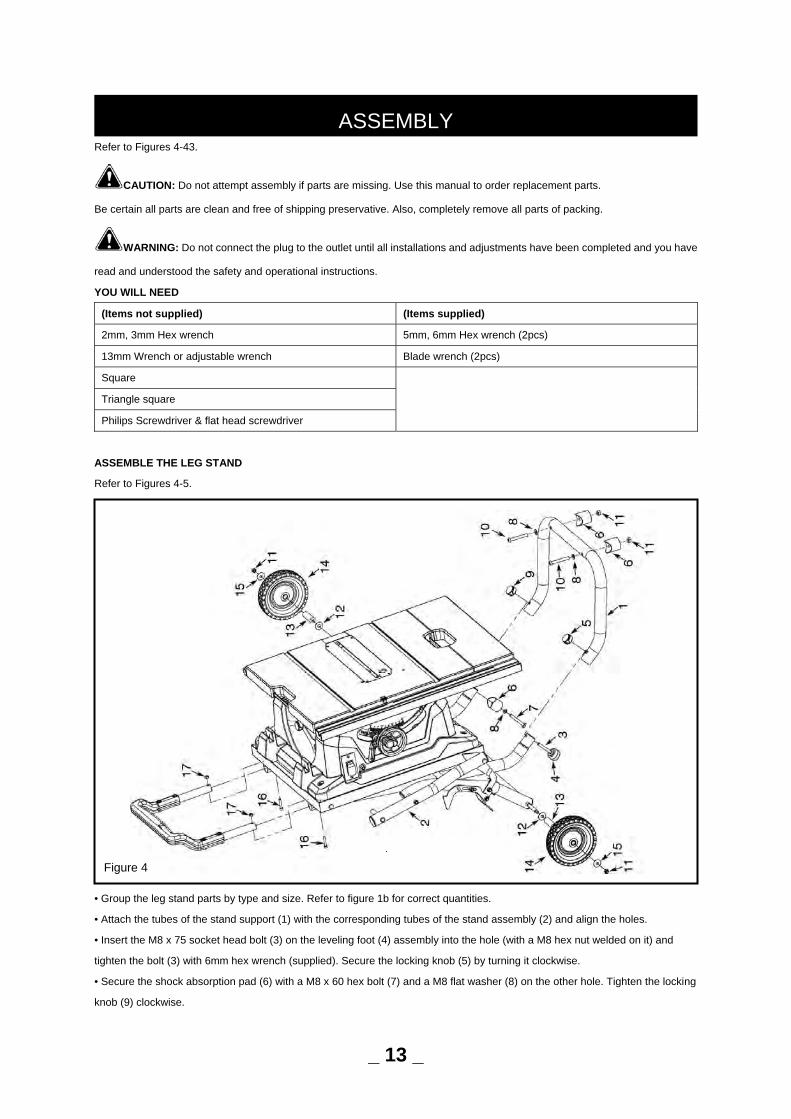
ASSEMBLE THE LEG STAND
Refer to Figures 4-5.
• Group the leg stand parts by type and size. Refer to figure 1b for correct quantities.
• Attach the tubes of the stand support (1) with the corresponding tubes of the stand assembly (2) and align the holes.
• Insert the M8 x 75 socket head bolt (3) on the leveling foot (4) assembly into the hole (with a M8 hex nut welded on it) and
tighten the bolt (3) with 6mm hex wrench (supplied). Secure the locking knob (5) by turning it clockwise.
• Secure the shock absorption pad (6) with a M8 x 60 hex bolt (7) and a M8 flat washer (8) on the other hole. Tighten the locking
knob (9) clockwise.
ASSEMBLY
_ 13 _
Figure 4
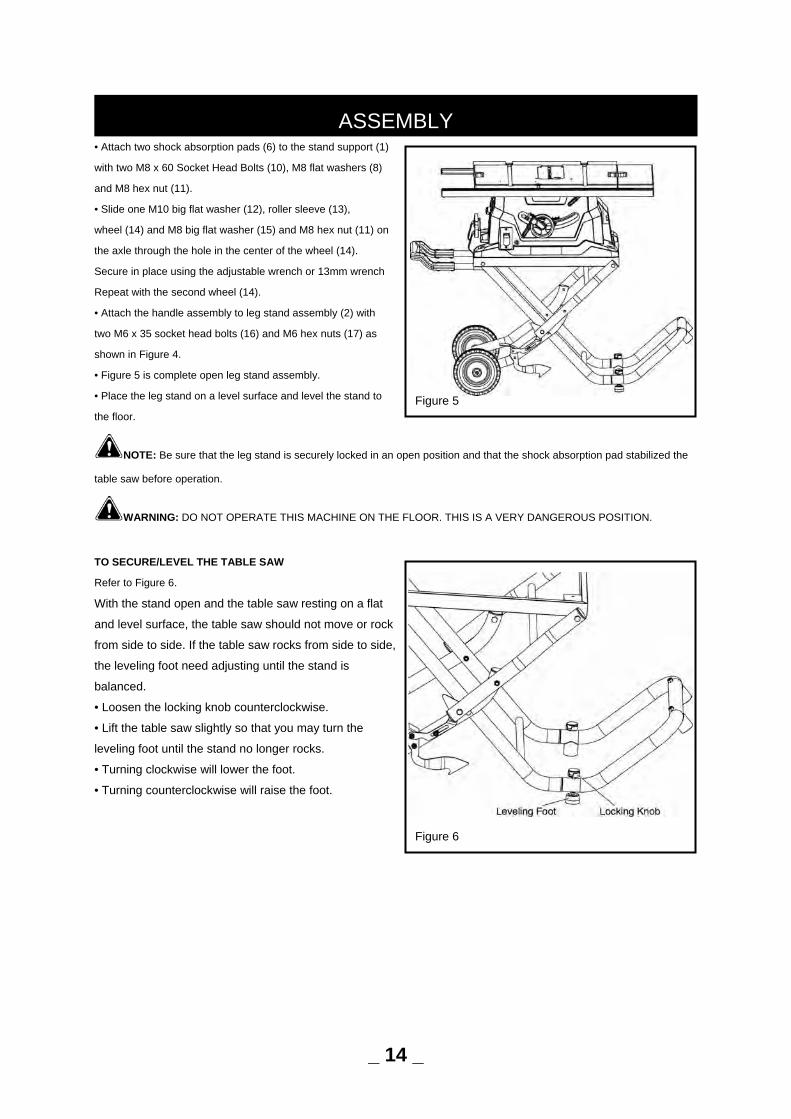
• Attach two shock absorption pads (6) to the stand support (1)
with two M8 x 60 Socket Head Bolts (10), M8 flat washers (8)
and M8 hex nut (11).
• Slide one M10 big flat washer (12), roller sleeve (13),
wheel (14) and M8 big flat washer (15) and M8 hex nut (11) on
the axle through the hole in the center of the wheel (14).
Secure in place using the adjustable wrench or 13mm wrench
Repeat with the second wheel (14).
• Attach the handle assembly to leg stand assembly (2) with
two M6 x 35 socket head bolts (16) and M6 hex nuts (17) as
shown in Figure 4.
• Figure 5 is complete open leg stand assembly.
• Place the leg stand on a level surface and level the stand to
the floor.
NOTE: Be sure that the leg stand is securely locked in an open position and that the shock absorption pad stabilized the
table saw before operation.
WARNING: DO NOT OPERATE THIS MACHINE ON THE FLOOR. THIS IS A VERY DANGEROUS POSITION.
TO SECURE/LEVEL THE TABLE SAW
Refer to Figure 6.
With the stand open and the table saw resting on a flat
and level surface, the table saw should not move or rock
from side to side. If the table saw rocks from side to side,
the leveling foot need adjusting until the stand is
balanced.
• Loosen the locking knob counterclockwise.
• Lift the table saw slightly so that you may turn the
leveling foot until the stand no longer rocks.
• Turning clockwise will lower the foot.
• Turning counterclockwise will raise the foot.
ASSEMBLY
Figure 6
_ 14 _
Figure 5
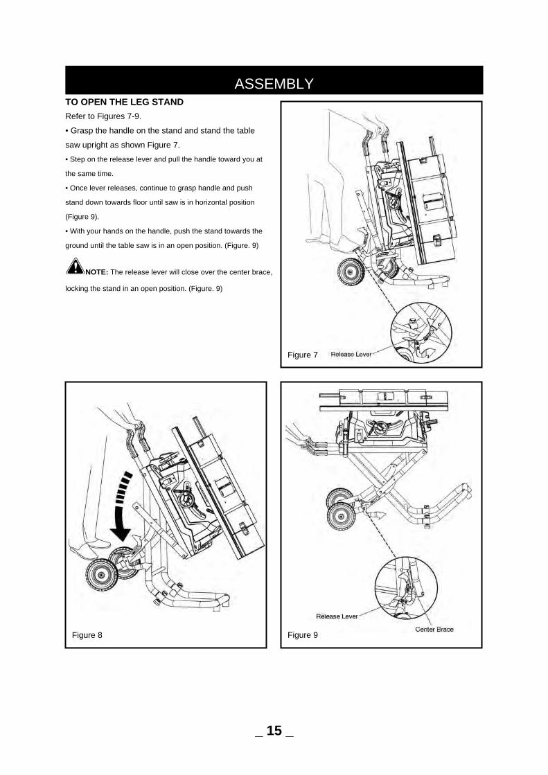
TO OPEN THE LEG STAND Refer to Figures 7-9.
• Grasp the handle on the stand and stand the table
saw upright as shown Figure 7.
• Step on the release lever and pull the handle toward you at
the same time.
• Once lever releases, continue to grasp handle and push
stand down towards floor until saw is in horizontal position
(Figure 9).
• With your hands on the handle, push the stand towards the
ground until the table saw is in an open position. (Figure. 9)
NOTE: The release lever will close over the center brace,
locking the stand in an open position. (Figure. 9)
ASSEMBLY
Figure 8
_ 15 _
Figure 7
Figure 9
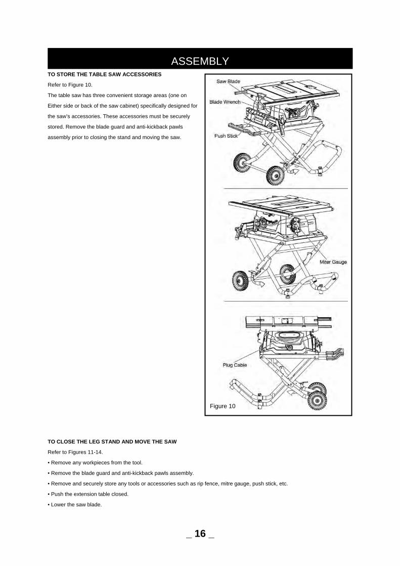
TO STORE THE TABLE SAW ACCESSORIES
Refer to Figure 10.
The table saw has three convenient storage areas (one on
Either side or back of the saw cabinet) specifically designed for
the saw’s accessories. These accessories must be securely
stored. Remove the blade guard and anti-kickback pawls
assembly prior to closing the stand and moving the saw.
TO CLOSE THE LEG STAND AND MOVE THE SAW
Refer to Figures 11-14.
• Remove any workpieces from the tool.
• Remove the blade guard and anti-kickback pawls assembly.
• Remove and securely store any tools or accessories such as rip fence, mitre gauge, push stick, etc.
• Push the extension table closed.
• Lower the saw blade.
ASSEMBLY
_ 16 _
Figure 10
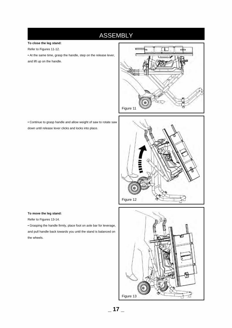
To close the leg stand:
Refer to Figures 11-12.
• At the same time, grasp the handle, step on the release lever,
and lift up on the handle.
• Continue to grasp handle and allow weight of saw to rotate saw
down until release lever clicks and locks into place.
To move the leg stand:
Refer to Figures 13-14.
• Grasping the handle firmly, place foot on axle bar for leverage,
and pull handle back towards you until the stand is balanced on
the wheels.
ASSEMBLY
_ 17 _
Figure 11
Figure 12
Figure 13
• Push the table saw to the desired location then either open
the stand for saw operation or store the table saw in a dry
environment.
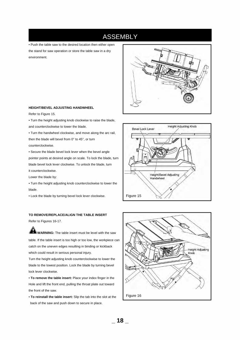
HEIGHT/BEVEL ADJUSTING HANDWHEEL
Refer to Figure 15.
• Turn the height adjusting knob clockwise to raise the blade,
and counterclockwise to lower the blade.
• Turn the handwheel clockwise, and move along the arc rail,
then the blade will bevel from 0° to 45°, or turn
counterclockwise.
• Secure the blade bevel lock lever when the bevel angle
pointer points at desired angle on scale. To lock the blade, turn
blade bevel lock lever clockwise. To unlock the blade, turn
it counterclockwise.
Lower the blade by:
• Turn the height adjusting knob counterclockwise to lower the
blade.
• Lock the blade by turning bevel lock lever clockwise.
TO REMOVE/REPLACE/ALIGN THE TABLE INSERT
Refer to Figures 16-17.
WARNING: The table insert must be level with the saw
table. If the table insert is too high or too low, the workpiece can
catch on the uneven edges resulting in binding or kickback
which could result in serious personal injury.
Turn the height adjusting knob counterclockwise to lower the
blade to the lowest position. Lock the blade by turning bevel
lock lever clockwise.
• To remove the table insert: Place your index finger in the
Hole and lift the front end, pulling the throat plate out toward
the front of the saw.
• To reinstall the table insert: Slip the tab into the slot at the
back of the saw and push down to secure in place.
ASSEMBLY
_ 18 _
Figure 15
Figure 16
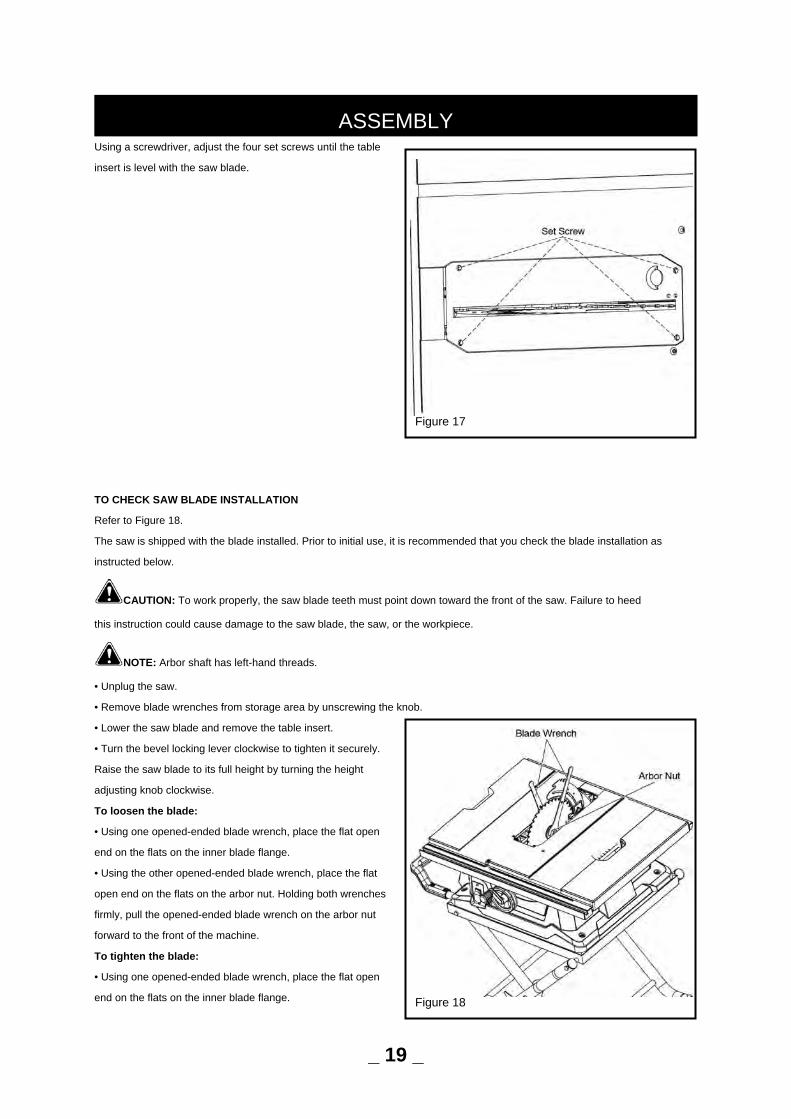
Using a screwdriver, adjust the four set screws until the table
insert is level with the saw blade.
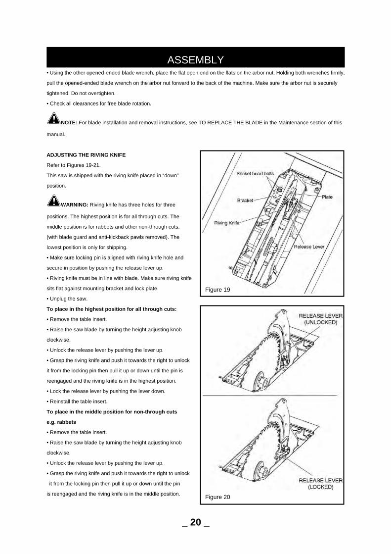
TO CHECK SAW BLADE INSTALLATION
Refer to Figure 18.
The saw is shipped with the blade installed. Prior to initial use, it is recommended that you check the blade installation as
instructed below.
CAUTION: To work properly, the saw blade teeth must point down toward the front of the saw. Failure to heed
this instruction could cause damage to the saw blade, the saw, or the workpiece.
NOTE: Arbor shaft has left-hand threads.
• Unplug the saw.
• Remove blade wrenches from storage area by unscrewing the knob.
• Lower the saw blade and remove the table insert.
• Turn the bevel locking lever clockwise to tighten it securely.
Raise the saw blade to its full height by turning the height
adjusting knob clockwise.
To loosen the blade:
• Using one opened-ended blade wrench, place the flat open
end on the flats on the inner blade flange.
• Using the other opened-ended blade wrench, place the flat
open end on the flats on the arbor nut. Holding both wrenches
firmly, pull the opened-ended blade wrench on the arbor nut
forward to the front of the machine.
To tighten the blade:
• Using one opened-ended blade wrench, place the flat open
end on the flats on the inner blade flange.
ASSEMBLY
Figure 17
Figure 18
_ 19 _
• Using the other opened-ended blade wrench, place the flat open end on the flats on the arbor nut. Holding both wrenches firmly,
pull the opened-ended blade wrench on the arbor nut forward to the back of the machine. Make sure the arbor nut is securely
tightened. Do not overtighten.
• Check all clearances for free blade rotation.
NOTE: For blade installation and removal instructions, see TO REPLACE THE BLADE in the Maintenance section of this
manual.
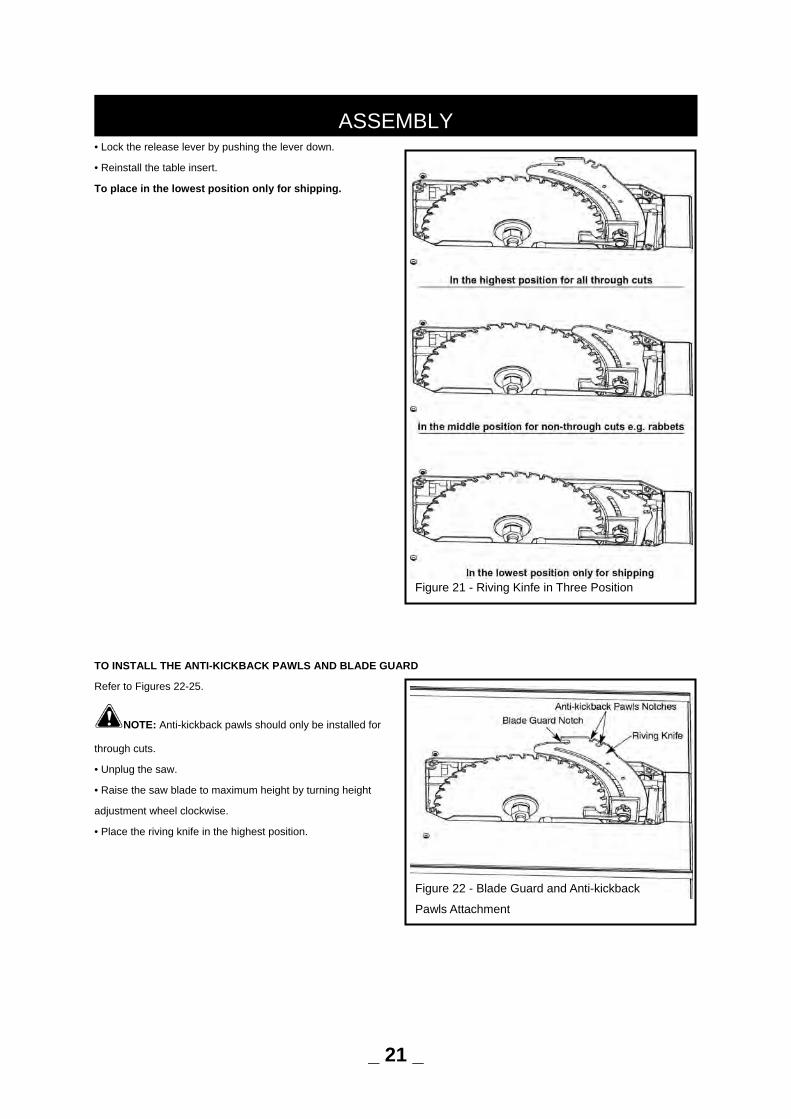
ADJUSTING THE RIVING KNIFE
Refer to Figures 19-21.
This saw is shipped with the riving knife placed in “down”
position.
WARNING: Riving knife has three holes for three
positions. The highest position is for all through cuts. The
middle position is for rabbets and other non-through cuts,
(with blade guard and anti-kickback pawls removed). The
lowest position is only for shipping.
• Make sure locking pin is aligned with riving knife hole and
secure in position by pushing the release lever up.
• Riving knife must be in line with blade. Make sure riving knife
sits flat against mounting bracket and lock plate.
• Unplug the saw.
To place in the highest position for all through cuts:
• Remove the table insert.
• Raise the saw blade by turning the height adjusting knob
clockwise.
• Unlock the release lever by pushing the lever up.
• Grasp the riving knife and push it towards the right to unlock
it from the locking pin then pull it up or down until the pin is
reengaged and the riving knife is in the highest position.
• Lock the release lever by pushing the lever down.
• Reinstall the table insert.
To place in the middle position for non-through cuts
e.g. rabbets
• Remove the table insert.
• Raise the saw blade by turning the height adjusting knob
clockwise.
• Unlock the release lever by pushing the lever up.
• Grasp the riving knife and push it towards the right to unlock
it from the locking pin then pull it up or down until the pin
is reengaged and the riving knife is in the middle position.
ASSEMBLY
Figure 19
Figure 20
_ 20 _
• Lock the release lever by pushing the lever down.
• Reinstall the table insert.
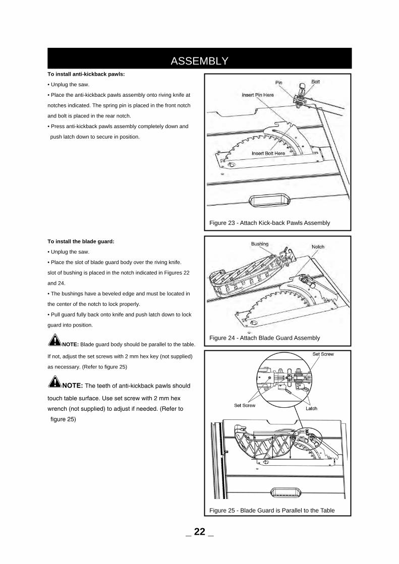
To place in the lowest position only for shipping.
TO INSTALL THE ANTI-KICKBACK PAWLS AND BLADE GUARD
Refer to Figures 22-25.
NOTE: Anti-kickback pawls should only be installed for
through cuts.
• Unplug the saw.
• Raise the saw blade to maximum height by turning height
adjustment wheel clockwise.
• Place the riving knife in the highest position.
ASSEMBLY
Figure 21 - Riving Kinfe in Three Position
Figure 22 - Blade Guard and Anti-kickback
Pawls Attachment
_ 21 _
To install anti-kickback pawls:
• Unplug the saw.
• Place the anti-kickback pawls assembly onto riving knife at
notches indicated. The spring pin is placed in the front notch
and bolt is placed in the rear notch.
• Press anti-kickback pawls assembly completely down and
push latch down to secure in position.
To install the blade guard:
• Unplug the saw.
• Place the slot of blade guard body over the riving knife.
slot of bushing is placed in the notch indicated in Figures 22
and 24.
• The bushings have a beveled edge and must be located in
the center of the notch to lock properly.
• Pull guard fully back onto knife and push latch down to lock
guard into position.
NOTE: Blade guard body should be parallel to the table.
If not, adjust the set screws with 2 mm hex key (not supplied)
as necessary. (Refer to figure 25)
NOTE: The teeth of anti-kickback pawls should
touch table surface. Use set screw with 2 mm hex
wrench (not supplied) to adjust if needed. (Refer to
figure 25)
ASSEMBLY
Figure 23 - Attach Kick-back Pawls Assembly
Figure 24 - Attach Blade Guard Assembly
Figure 25 - Blade Guard is Parallel to the Table
_ 22 _
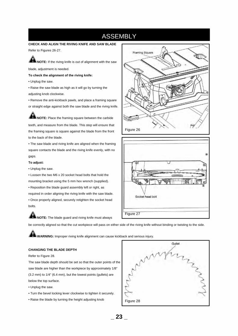
CHECK AND ALIGN THE RIVING KNIFE AND SAW BLADE
Refer to Figures 26-27.
NOTE: If the riving knife is out of alignment with the saw
blade, adjustment is needed.
To check the alignment of the riving knife:
• Unplug the saw.
• Raise the saw blade as high as it will go by turning the
adjusting knob clockwise.
• Remove the anti-kickback pawls, and place a framing square
or straight edge against both the saw blade and the riving knife.
NOTE: Place the framing square between the carbide
teeth, and measure from the blade. This step will ensure that
the framing square is square against the blade from the front
to the back of the blade.
• The saw blade and riving knife are aligned when the framing
square contacts the blade and the riving knife evenly, with no
gaps.
To adjust:
• Unplug the saw.
• Loosen the two M6 x 20 socket head bolts that hold the
mounting bracket using the 5 mm hex wrench (supplied).
• Reposition the blade guard assembly left or right, as
required in order aligning the riving knife with the saw blade.
• Once properly aligned, securely retighten the socket head
bolts.
NOTE: The blade guard and riving knife must always
be correctly aligned so that the cut workpiece will pass on either side of the riving knife without binding or twisting to the side.
WARNING: Improper riving knife alignment can cause kickback and serious injury.
CHANGING THE BLADE DEPTH
Refer to Figure 28.
The saw blade depth should be set so that the outer points of the
saw blade are higher than the workpiece by approximately 1/8”
(3.2 mm) to 1/4” (6.4 mm), but the lowest points (gullets) are
below the top surface.
• Unplug the saw.
• Turn the bevel locking lever clockwise to tighten it securely.
• Raise the blade by turning the height adjusting knob
ASSEMBLY
Figure 26
Figure 27
Figure 28
_ 23 _
clockwise, or lower it by turning the handle counterclockwise.
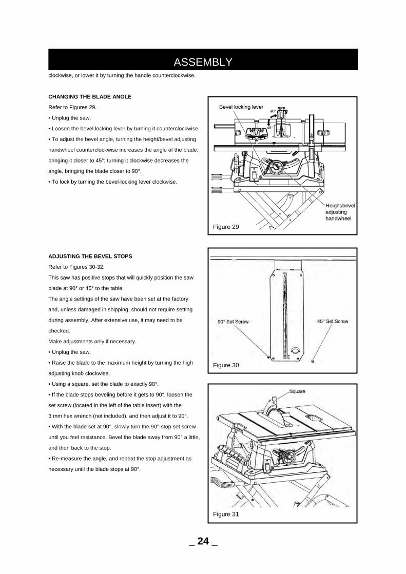
CHANGING THE BLADE ANGLE
Refer to Figures 29.
• Unplug the saw.
• Loosen the bevel locking lever by turning it counterclockwise.
• To adjust the bevel angle, turning the height/bevel adjusting
handwheel counterclockwise increases the angle of the blade,
bringing it closer to 45°; turning it clockwise decreases the
angle, bringing the blade closer to 90°.
• To lock by turning the bevel-locking lever clockwise.
ADJUSTING THE BEVEL STOPS
Refer to Figures 30-32.
This saw has positive stops that will quickly position the saw
blade at 90° or 45° to the table.
The angle settings of the saw have been set at the factory
and, unless damaged in shipping, should not require setting
during assembly. After extensive use, it may need to be
checked.
Make adjustments only if necessary.
• Unplug the saw.
• Raise the blade to the maximum height by turning the high
adjusting knob clockwise.
• Using a square, set the blade to exactly 90°.
• If the blade stops beveling before it gets to 90°, loosen the
set screw (located in the left of the table insert) with the
3 mm hex wrench (not included), and then adjust it to 90°.
• With the blade set at 90°, slowly turn the 90°-stop set screw
until you feel resistance. Bevel the blade away from 90° a little,
and then back to the stop.
• Re-measure the angle, and repeat the stop adjustment as
necessary until the blade stops at 90°.
ASSEMBLY
Figure 30
Figure 31
_ 24 _
Figure 29
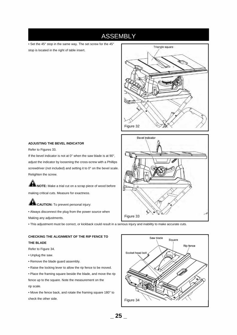
• Set the 45° stop in the same way. The set screw for the 45°
stop is located in the right of table insert.
ADJUSTING THE BEVEL INDICATOR
Refer to Figures 33.
If the bevel indicator is not at 0° when the saw blade is at 90°,
adjust the indicator by loosening the cross-screw with a Phillips
screwdriver (not included) and setting it to 0° on the bevel scale.
Retighten the screw.
NOTE: Make a trial cut on a scrap piece of wood before
making critical cuts. Measure for exactness.
CAUTION: To prevent personal injury:
• Always disconnect the plug from the power source when
Making any adjustments.
• This adjustment must be correct, or kickback could result in a serious injury and inability to make accurate cuts.
CHECKING THE ALIGNMENT OF THE RIP FENCE TO
THE BLADE
Refer to Figure 34.
• Unplug the saw.
• Remove the blade guard assembly.
• Raise the locking lever to allow the rip fence to be moved.
• Place the framing square beside the blade, and move the rip
fence up to the square. Note the measurement on the
rip scale.
• Move the fence back, and rotate the framing square 180° to
check the other side.
ASSEMBLY
Figure 32
Figure 33
Figure 34
_ 25 _
• If the two measurements are not the same, loosen the two M6 x 16 socket head bolts on the fence using a 5 mm hex
key (not included), and then align it.
• Retighten the two socket head bolts.
• Make two or three test cuts using scrap wood. If the cuts are not true, repeat the process.
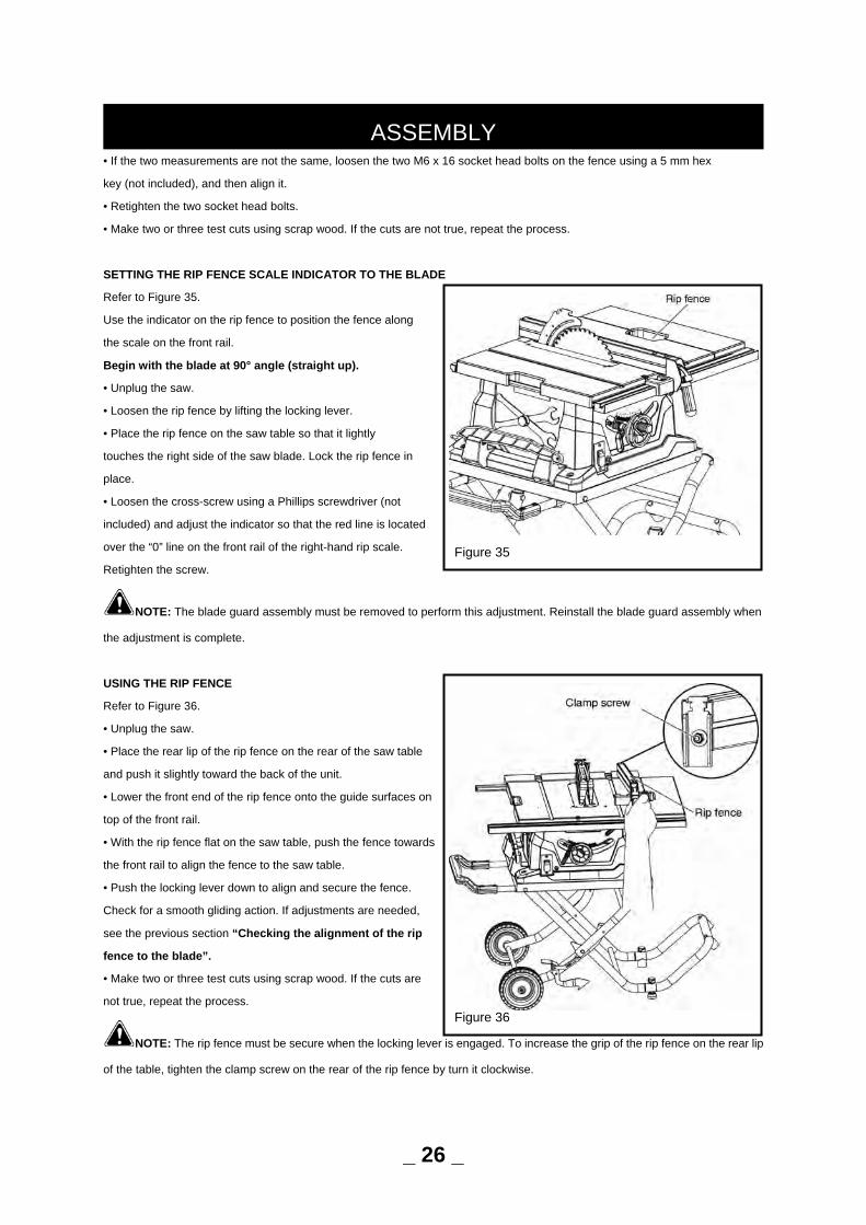
SETTING THE RIP FENCE SCALE INDICATOR TO THE BLADE
Refer to Figure 35.
Use the indicator on the rip fence to position the fence along
the scale on the front rail.
Begin with the blade at 90° angle (straight up).
• Unplug the saw.
• Loosen the rip fence by lifting the locking lever.
• Place the rip fence on the saw table so that it lightly
touches the right side of the saw blade. Lock the rip fence in
place.
• Loosen the cross-screw using a Phillips screwdriver (not
included) and adjust the indicator so that the red line is located
over the “0” line on the front rail of the right-hand rip scale.
Retighten the screw.
NOTE: The blade guard assembly must be removed to perform this adjustment. Reinstall the blade guard assembly when
the adjustment is complete.
USING THE RIP FENCE
Refer to Figure 36.
• Unplug the saw.
• Place the rear lip of the rip fence on the rear of the saw table
and push it slightly toward the back of the unit.
• Lower the front end of the rip fence onto the guide surfaces on
top of the front rail.
• With the rip fence flat on the saw table, push the fence towards
the front rail to align the fence to the saw table.
• Push the locking lever down to align and secure the fence.
Check for a smooth gliding action. If adjustments are needed,
see the previous section “Checking the alignment of the rip
fence to the blade”.
• Make two or three test cuts using scrap wood. If the cuts are
not true, repeat the process.
NOTE: The rip fence must be secure when the locking lever is engaged. To increase the grip of the rip fence on the rear lip
of the table, tighten the clamp screw on the rear of the rip fence by turn it clockwise.
ASSEMBLY
Figure 35
_ 26 _
Figure 36
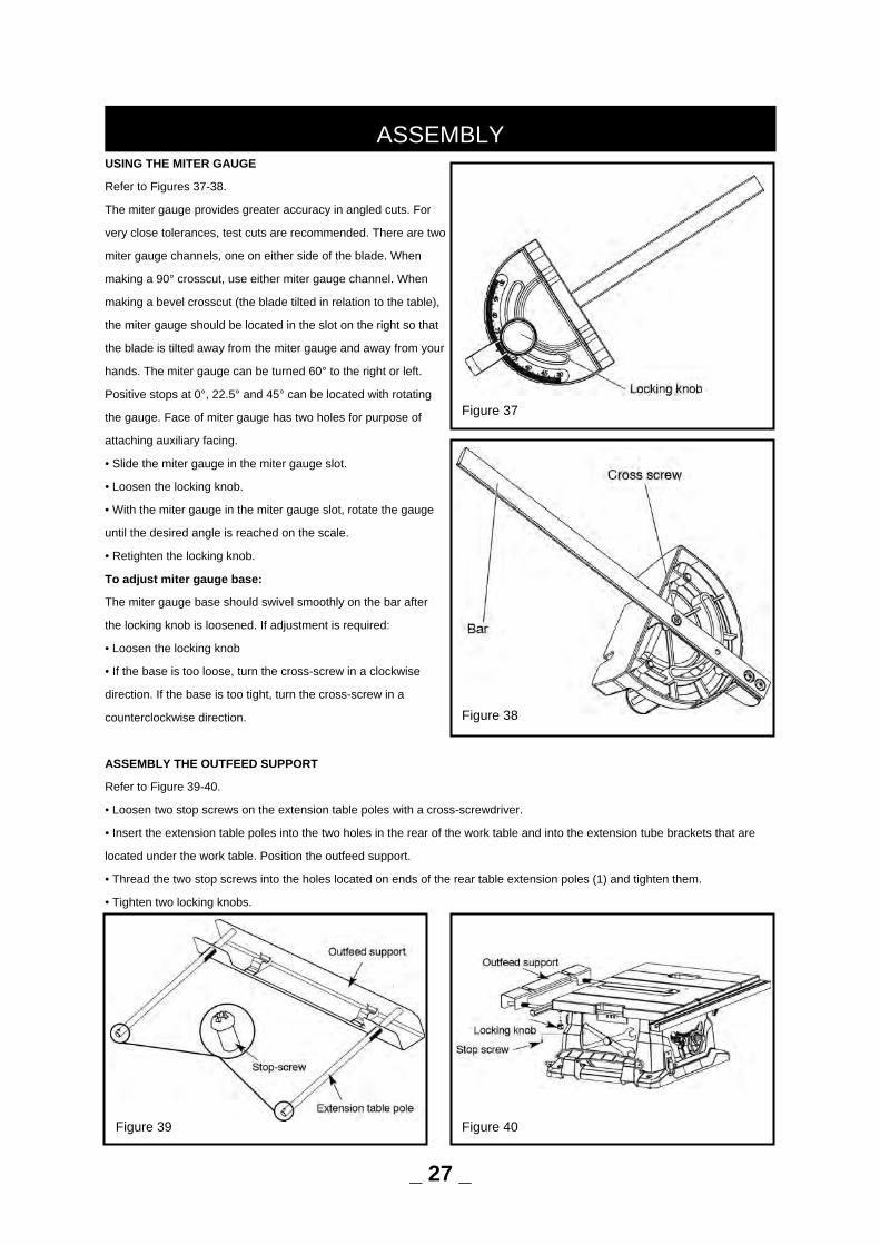
USING THE MITER GAUGE
Refer to Figures 37-38.
The miter gauge provides greater accuracy in angled cuts. For
very close tolerances, test cuts are recommended. There are two
miter gauge channels, one on either side of the blade. When
making a 90° crosscut, use either miter gauge channel. When
making a bevel crosscut (the blade tilted in relation to the table),
the miter gauge should be located in the slot on the right so that
the blade is tilted away from the miter gauge and away from your
hands. The miter gauge can be turned 60° to the right or left.
Positive stops at 0°, 22.5° and 45° can be located with rotating
the gauge. Face of miter gauge has two holes for purpose of
attaching auxiliary facing.
• Slide the miter gauge in the miter gauge slot.
• Loosen the locking knob.
• With the miter gauge in the miter gauge slot, rotate the gauge
until the desired angle is reached on the scale.
• Retighten the locking knob.
To adjust miter gauge base:
The miter gauge base should swivel smoothly on the bar after
the locking knob is loosened. If adjustment is required:
• Loosen the locking knob
• If the base is too loose, turn the cross-screw in a clockwise
direction. If the base is too tight, turn the cross-screw in a
counterclockwise direction.
ASSEMBLY THE OUTFEED SUPPORT Refer to Figure 39-40.
• Loosen two stop screws on the extension table poles with a cross-screwdriver.
• Insert the extension table poles into the two holes in the rear of the work table and into the extension tube brackets that are
located under the work table. Position the outfeed support.
• Thread the two stop screws into the holes located on ends of the rear table extension poles (1) and tighten them.
• Tighten two locking knobs.
ASSEMBLY
Figure 38
Figure 40
_ 27 _
Figure 37
Figure 39
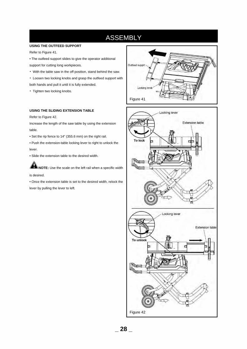
USING THE OUTFEED SUPPORT
Refer to Figure 41.
• The outfeed support slides to give the operator additional
support for cutting long workpieces.
• With the table saw in the off position, stand behind the saw.
• Loosen two locking knobs and grasp the outfeed support with
both hands and pull it until it is fully extended.
• Tighten two locking knobs.
USING THE SLIDING EXTENSION TABLE
Refer to Figure 42.
Increase the length of the saw table by using the extension
table.
• Set the rip fence to 14” (355.6 mm) on the right rail.
• Push the extension-table locking lever to right to unlock the
lever.
• Slide the extension table to the desired width.
NOTE: Use the scale on the left rail when a specific width
is desired.
• Once the extension table is set to the desired width, relock the
lever by pulling the lever to left.
ASSEMBLY
_ 28 _
Figure 42
Figure 41
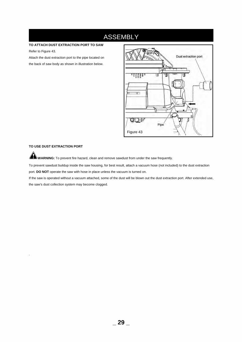
TO ATTACH DUST EXTRACTION PORT TO SAW
Refer to Figure 43.
Attach the dust extraction port to the pipe located on
the back of saw body as shown in illustration below.
TO USE DUST EXTRACTION PORT
WARNING: To prevent fire hazard, clean and remove sawdust from under the saw frequently.
To prevent sawdust buildup inside the saw housing, for best result, attach a vacuum hose (not included) to the dust extraction
port. DO NOT operate the saw with hose in place unless the vacuum is turned on.
If the saw is operated without a vacuum attached, some of the dust will be blown out the dust extraction port. After extended use,
the saw’s dust collection system may become clogged.
.
ASSEMBLY
Figure 43
_ 29 _
Refer to Figures 44-45.
GROUNDING INSTRUCTIONS
WARNING: Improper connection of equipment grounding conductor can result in the risk of electrical shock. Equipment
should be grounded while in use to protect operator from electrical shock.
• Check with a qualified electrician if grounding instructions are not understood or if in doubt as to whether the tool
is properly grounded.
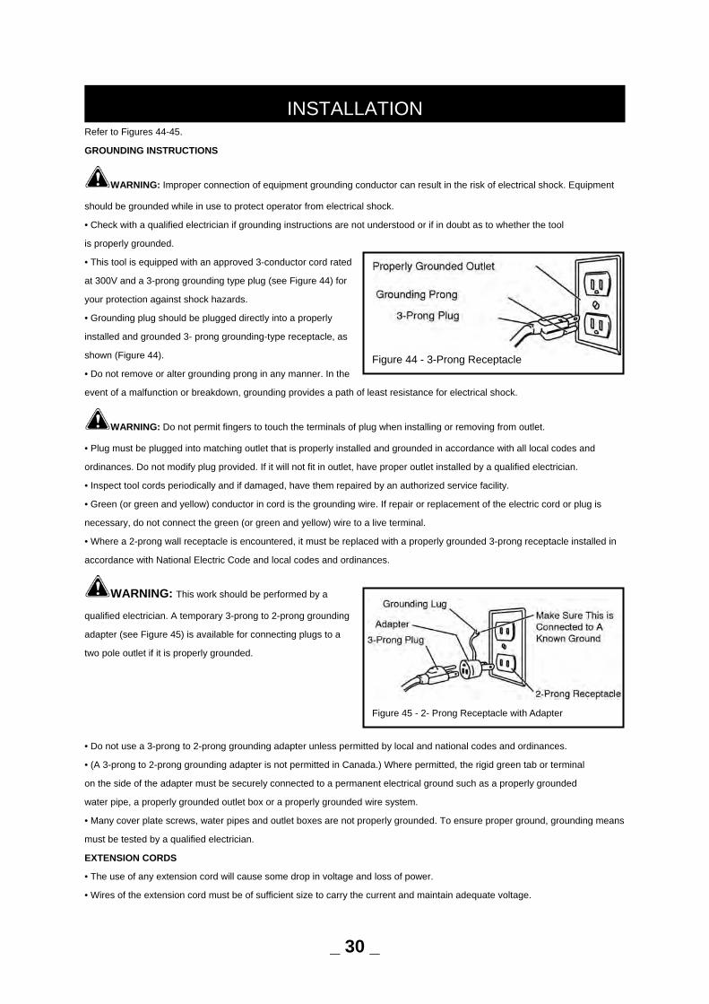
• This tool is equipped with an approved 3-conductor cord rated
at 300V and a 3-prong grounding type plug (see Figure 44) for
your protection against shock hazards.
• Grounding plug should be plugged directly into a properly
installed and grounded 3- prong grounding-type receptacle, as
shown (Figure 44).
• Do not remove or alter grounding prong in any manner. In the
event of a malfunction or breakdown, grounding provides a path of least resistance for electrical shock.
WARNING: Do not permit fingers to touch the terminals of plug when installing or removing from outlet.
• Plug must be plugged into matching outlet that is properly installed and grounded in accordance with all local codes and
ordinances. Do not modify plug provided. If it will not fit in outlet, have proper outlet installed by a qualified electrician.
• Inspect tool cords periodically and if damaged, have them repaired by an authorized service facility.
• Green (or green and yellow) conductor in cord is the grounding wire. If repair or replacement of the electric cord or plug is
necessary, do not connect the green (or green and yellow) wire to a live terminal.
• Where a 2-prong wall receptacle is encountered, it must be replaced with a properly grounded 3-prong receptacle installed in
accordance with National Electric Code and local codes and ordinances.
WARNING: This work should be performed by a
qualified electrician. A temporary 3-prong to 2-prong grounding
adapter (see Figure 45) is available for connecting plugs to a
two pole outlet if it is properly grounded.
• Do not use a 3-prong to 2-prong grounding adapter unless permitted by local and national codes and ordinances.
• (A 3-prong to 2-prong grounding adapter is not permitted in Canada.) Where permitted, the rigid green tab or terminal
on the side of the adapter must be securely connected to a permanent electrical ground such as a properly grounded
water pipe, a properly grounded outlet box or a properly grounded wire system.
• Many cover plate screws, water pipes and outlet boxes are not properly grounded. To ensure proper ground, grounding means
must be tested by a qualified electrician.
EXTENSION CORDS
• The use of any extension cord will cause some drop in voltage and loss of power.
• Wires of the extension cord must be of sufficient size to carry the current and maintain adequate voltage.
INSTALLATION
Figure 44 - 3-Prong Receptacle
Figure 45 - 2- Prong Receptacle with Adapter
_ 30 _

• Use the table to determine the minimum wire size (A.W.G.) extension cord.
• Use only 3-wire extension cords having 3-prong grounding type plugs and 3-pole receptacles which accept the tool plug.
• If the extension cord is worn, cut, or damaged in any way, replace it immediately.
Extension Cord Length (120V Operation)
Wire Size A.W.G.
Up to 25 ft. . . . . . . . . . . . . . . . . . . . . . . . . . . . . . . . . . . . . . . .14
Up to 50 ft. . . . . . . . . . . . . . . . . . . . . . . . . . . . . . . . . . . . . . . .12
NOTE: Using extension cords over 50 ft. long is not recommended.
Extension Cord Length (240V Operation)
Wire Size A.W.G.
Up to 50 ft. . . . . . . . . . . . . . . . . . . . . . . . . . . . . . . . . . . . . . . .18
50 to 100 ft. . . . . . . . . . . . . . . . . . . . . . . . . . . . . . . . . . . . . . .16
100 to 200 ft. . . . . . . . . . . . . . . . . . . . . . . . . . . . . . . . . . . . . .14
200 to 300 ft. . . . . . . . . . . . . . . . . . . . . . . . . . . . . . . . . . . . . .12
NOTE: Using extension cords over 300 ft. long is not recommended.
ELECTRICAL CONNECTIONS
WARNING: All electrical connections must be performed by a qualified electrician. Make sure tool is off and disconnected
from power source before inspecting any wiring. The saw is prewired for use on a 120 volt, 60Hz power supply. The power lines
are inserted directly onto the switch. The green ground line must remain securely fastened to the frame to properly protect
against electrical shock.
• Remove the key to prevent unauthorized use.
INSTALLATION
_ 31 _
Refer to Figures 46-60.
DESCRIPTION
The PERFORMAX 10”Model Number 240-3605 table saw offers precise cutting performance for all woods up to 3-1/2” (89 mm)
thick. The 10” Table Saw is recommended for use with a 10” blade.
The saw features a right extension table with ripping capacity of 30” (762 mm). Saw body has on board storage for push stick,
miter gauge, rip fence and saw blades and blade wrenches. Saw is equipped with a riving knife and a clear acrylic blade guard
with anti-kickback feature. Cabinet is constructed of plastic and includes a dust extraction port.
Rip Fence Assembly features a precision rip fence that is designed for simple and one-hand maneuverability. Front rail is
calibrated in inches. Foldable Leg Stand with wheels features an easy transport and storage.
WARNING: Disconnect power before attempting any of the following procedures. Be certain switch is in OFF position and
the key is removed. Saw blade must not be moving. Saw blade will rotate freely after motor is turned off. Allow blade to come to a
complete stop before attempting any of the following procedures.
WARNING: The operation of any power tool can result in foreign objects being thrown into the eyes, which can result in
severe eye damage. Always wear safety goggles complying with United States ANSI Z87.1 before commencing power tool
operation.
WARNING: Do not allow familiarity with a tool to make you careless. Remember that a fraction of a second of carelessness
is sufficient to cause serious injury.
WARNING: Do not use any attachments or accessories that are not recommended by the manufacturer of this tool. The
use of attachments or accessories that are not recommended can result in serious personal injury.
WARNING: Although many of the illustrations in this Operator’s Manual are shown with the blade guard removed for clarity,
do not operate the saw with-out the blade guard unless specifically instructed to do so.
WARNING: The table saw must be mounted to a firm, supporting, waist high surface, such as a workbench or leg stand.
Many illustrations in this Operator’s Manual are shown with the saw unmounted for clarity.
APPLICATIONS
You can use this tool for the purposes listed below:
• Straight-line cutting operations, such as crosscutting, ripping, mitering, beveling, and compound cutting.
• Cabinet making and woodworking
NOTE: This table saw is designed to cut wood and wood composition products only.
BASIC OPERATION OF THE TABLE SAW
The 3-pronged plug must be plugged into a matching outlet that is properly installed and grounded in compliance with all local
codes and ordinances. Improper connection of the equipment can result in electric shock. Check with an electrician or service
technician if you are unsure about proper grounding. Do not alter the plug. If it will not fit into the outlet, have the proper outlet
installed by a qualified electrician.
OPERATION
_ 32 _
CAUSES OF KICKBACK
Kickback can occur when the blade stalls or binds, causing the workpiece to be kicked back toward the operator with great force
and speed. If your hands are near the saw blade, they may be jerked loose from the workpiece and come into contact with the
blade. Obviously, kickback can cause serious injury, and it is well worth using precautions to avoid the risks. Kickback can be
caused by any action that pinches the blade in the wood, such as the following:
• Making a cut with incorrect blade depth.
• Sawing into knots or nails in the work piece.
• Twisting the wood while making a cut.
• Failing to support the workpiece.
• Forcing a cut.
• Cutting warped or wet lumber.
• Using the wrong blade for the type of cut.
• Not following correct operating procedures.
• Misusing the saw.
• Failing to use the anti-kickback pawls.
• Cutting with a dull, gummed-up, or improperly set blade.
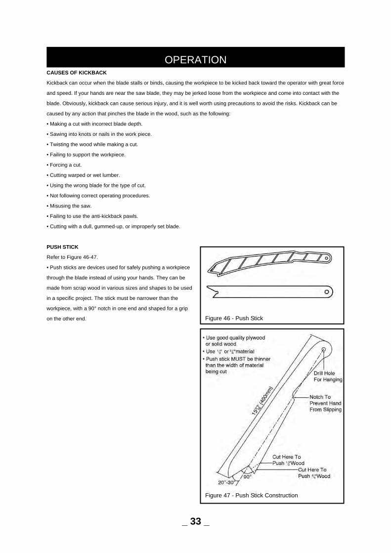
PUSH STICK
Refer to Figure 46-47.
• Push sticks are devices used for safely pushing a workpiece
through the blade instead of using your hands. They can be
made from scrap wood in various sizes and shapes to be used
in a specific project. The stick must be narrower than the
workpiece, with a 90° notch in one end and shaped for a grip
on the other end.
OPERATION
Figure 46 - Push Stick
Figure 47 - Push Stick Construction
_ 33 _
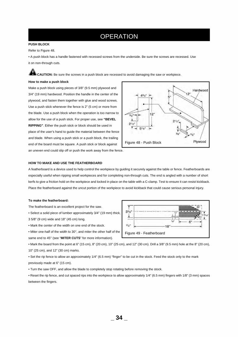
PUSH BLOCK
Refer to Figure 48.
• A push block has a handle fastened with recessed screws from the underside. Be sure the screws are recessed. Use
it on non-through cuts.
CAUTION: Be sure the screws in a push block are recessed to avoid damaging the saw or workpiece.
How to make a push block
Make a push block using pieces of 3/8” (9.5 mm) plywood and
3/4” (19 mm) hardwood. Position the handle in the center of the
plywood, and fasten them together with glue and wood screws.
Use a push stick whenever the fence is 2” (5 cm) or more from
the blade. Use a push block when the operation is too narrow to
allow for the use of a push stick. For proper use, see “BEVEL
RIPPING”. Either the push stick or block should be used in
place of the user’s hand to guide the material between the fence
and blade. When using a push stick or a push block, the trailing
end of the board must be square. A push stick or block against
an uneven end could slip off or push the work away from the fence.
HOW TO MAKE AND USE THE FEATHERBOARD
A featherboard is a device used to help control the workpiece by guiding it securely against the table or fence. Featherboards are
especially useful when ripping small workpieces and for completing non-through cuts. The end is angled with a number of short
kerfs to give a friction hold on the workpiece and locked in place on the table with a C-clamp. Test to ensure it can resist kickback.
Place the featherboard against the uncut portion of the workpiece to avoid kickback that could cause serious personal injury.
To make the featherboard:
The featherboard is an excellent project for the saw.
• Select a solid piece of lumber approximately 3/4” (19 mm) thick,
3 5/8” (9 cm) wide and 18” (45 cm) long.
• Mark the center of the width on one end of the stock.
• Miter one-half of the width to 30°, and miter the other half of the
same end to 45° (see “MITER CUTS” for more information).
• Mark the board from the point at 6” (15 cm), 8” (20 cm), 10” (25 cm), and 12” (30 cm). Drill a 3/8” (9.5 mm) hole at the 8” (20 cm),
10” (25 cm), and 12” (30 cm) marks.
• Set the rip fence to allow an approximately 1/4” (6.5 mm) “finger” to be cut in the stock. Feed the stock only to the mark
previously made at 6” (15 cm).
• Turn the saw OFF, and allow the blade to completely stop rotating before removing the stock.
• Reset the rip fence, and cut spaced rips into the workpiece to allow approximately 1/4” (6.5 mm) fingers with 1/8” (3 mm) spaces
between the fingers.
OPERATION
Figure 49 - Featherboard
_ 34 _
Figure 48 - Push Block
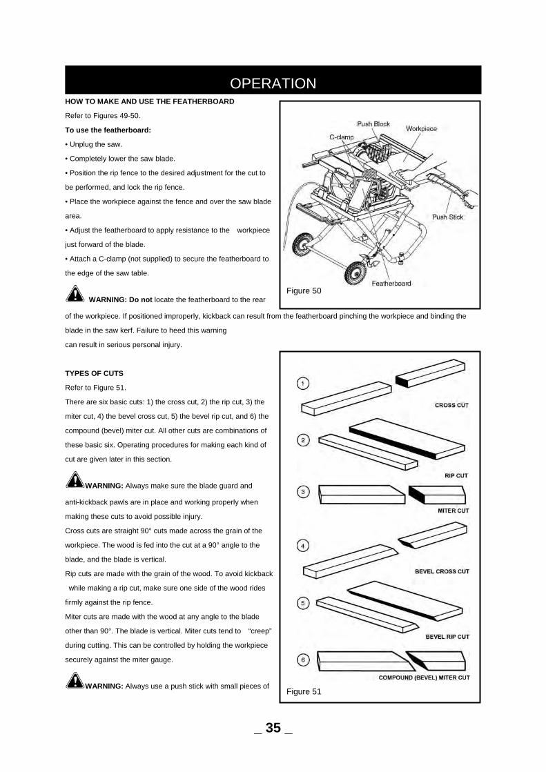
HOW TO MAKE AND USE THE FEATHERBOARD
Refer to Figures 49-50.
To use the featherboard:
• Unplug the saw.
• Completely lower the saw blade.
• Position the rip fence to the desired adjustment for the cut to
be performed, and lock the rip fence.
• Place the workpiece against the fence and over the saw blade
area.
• Adjust the featherboard to apply resistance to the workpiece
just forward of the blade.
• Attach a C-clamp (not supplied) to secure the featherboard to
the edge of the saw table.
WARNING: Do not locate the featherboard to the rear
of the workpiece. If positioned improperly, kickback can result from the featherboard pinching the workpiece and binding the
blade in the saw kerf. Failure to heed this warning
can result in serious personal injury.
TYPES OF CUTS
Refer to Figure 51.
There are six basic cuts: 1) the cross cut, 2) the rip cut, 3) the
miter cut, 4) the bevel cross cut, 5) the bevel rip cut, and 6) the
compound (bevel) miter cut. All other cuts are combinations of
these basic six. Operating procedures for making each kind of
cut are given later in this section.
WARNING: Always make sure the blade guard and
anti-kickback pawls are in place and working properly when
making these cuts to avoid possible injury.
Cross cuts are straight 90° cuts made across the grain of the
workpiece. The wood is fed into the cut at a 90° angle to the
blade, and the blade is vertical.
Rip cuts are made with the grain of the wood. To avoid kickback
while making a rip cut, make sure one side of the wood rides
firmly against the rip fence.
Miter cuts are made with the wood at any angle to the blade
other than 90°. The blade is vertical. Miter cuts tend to “creep”
during cutting. This can be controlled by holding the workpiece
securely against the miter gauge.
WARNING: Always use a push stick with small pieces of
OPERATION
Figure 50
Figure 51
_ 35 _
wood, and also to finish the cut when ripping a long narrow piece of wood, to prevent your hands from getting close to the blade.
Bevel cuts are made with an angled blade. Bevel cross cuts are across the wood grain, and bevel rip cuts are with the grain. The
rip fence must always be on the right side of the blade for bevel rip cuts.
Compound (or bevel) miter cuts are made with an angled blade on wood that is angled to the blade. Be thoroughly familiar with
making cross cuts, rip cuts, bevel cuts, and miter cuts before trying a compound miter cut.
WARNING: Do not use blades rated less than the speed of this tool. Failure to heed this warning could result in personal
injury.
• The kerf (the cut made by the blade in the wood) will be wider than the blade to avoid overheating or binding. Make allowance
for the kerf when measuring wood.
• Make sure the kerf is made on the waste side of the measuring line.
• Cut the wood with the finish side up.
• Knock out any loose knots with a hammer before making the cut.
• Always provide proper support for the wood as it comes out of the saw.
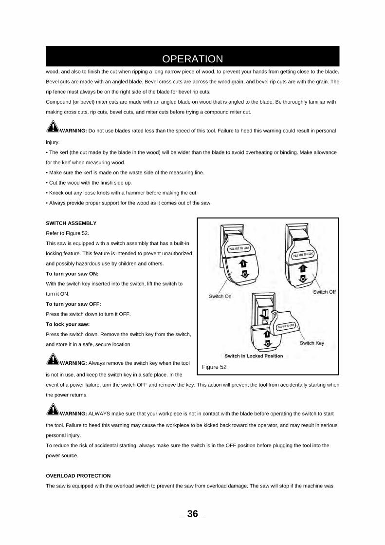
SWITCH ASSEMBLY
Refer to Figure 52.
This saw is equipped with a switch assembly that has a built-in
locking feature. This feature is intended to prevent unauthorized
and possibly hazardous use by children and others.
To turn your saw ON:
With the switch key inserted into the switch, lift the switch to
turn it ON.
To turn your saw OFF:
Press the switch down to turn it OFF.
To lock your saw:
Press the switch down. Remove the switch key from the switch,
and store it in a safe, secure location
WARNING: Always remove the switch key when the tool
is not in use, and keep the switch key in a safe place. In the
event of a power failure, turn the switch OFF and remove the key. This action will prevent the tool from accidentally starting when
the power returns.
WARNING: ALWAYS make sure that your workpiece is not in contact with the blade before operating the switch to start
the tool. Failure to heed this warning may cause the workpiece to be kicked back toward the operator, and may result in serious
personal injury.
To reduce the risk of accidental starting, always make sure the switch is in the OFF position before plugging the tool into the
power source.
OVERLOAD PROTECTION
The saw is equipped with the overload switch to prevent the saw from overload damage. The saw will stop if the machine was
OPERATION
Figure 52
_ 36 _
with overloaded cutting or low voltage. Turn the switch to the OFF position and allow the motor to cool down for at least five
minutes. And press the overload switch button to resume the overload switch. After the motor has cooled down, turn the switch to
the ON position; the saw should now start.
SAW BLADE
For maximum performance, it is recommended that you use the 10”, 5/8”arbor holes and 40-tooth blade provided with your saw.
Additional blade styles of the same high quality are available for specific operations such as ripping. Your local dealer can
provide you with complete information.
WARNING: Do not use blades rated less than the speed of this tool. Failure to heed this warning could result in personal
injury.
WARNING: To prevent possible electrical hazards, have a qualified electrician check the line if you are not certain that it is
properly wired.
MAKING CUTS
The blade provided with the saw is a high-quality combination blade suitable for ripping and cross cut operations.
WARNING: Do not use blades rated less than the speed of this tool. Failure to heed this warning could result in personal injury.
Use the miter gauge when making cross, miter, bevel, and compound miter cuts. To secure the angle, lock the miter gauge in
place by twisting the lock knob clockwise. Always tighten the lock knob securely in place before use.
NOTE: It is recommended that you place the piece to be saved on the left side of the blade and that you make a test cut on
scrap wood first.
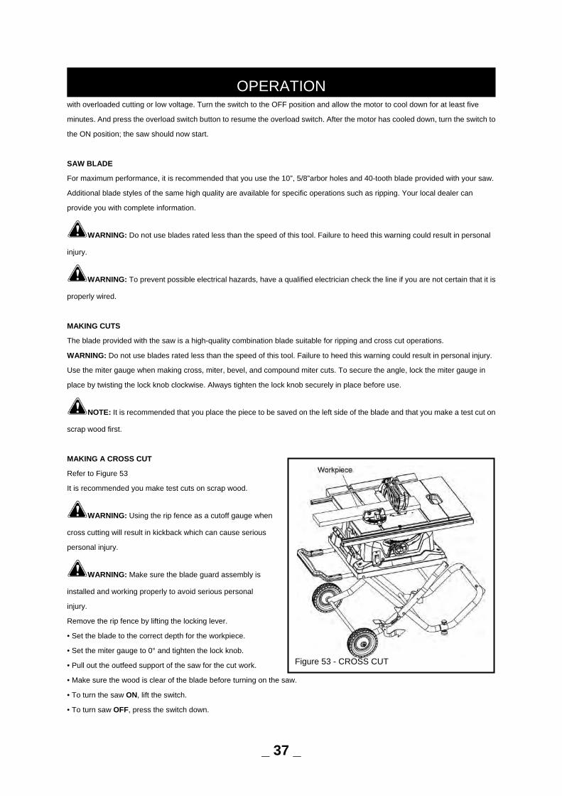
MAKING A CROSS CUT
Refer to Figure 53
It is recommended you make test cuts on scrap wood.
WARNING: Using the rip fence as a cutoff gauge when
cross cutting will result in kickback which can cause serious
personal injury.
WARNING: Make sure the blade guard assembly is
installed and working properly to avoid serious personal
injury.
Remove the rip fence by lifting the locking lever.
• Set the blade to the correct depth for the workpiece.
• Set the miter gauge to 0° and tighten the lock knob.
• Pull out the outfeed support of the saw for the cut work.
• Make sure the wood is clear of the blade before turning on the saw.
• To turn the saw ON, lift the switch.
• To turn saw OFF, press the switch down.
OPERATION
_ 37 _
Figure 53 - CROSS CUT
NOTE: To prevent unauthorized use, remove the switch key as shown in figure 52.
• Let the blade build up to full speed before moving the workpiece into the blade.
• Hold the workpiece firmly with both hands and feed the workpiece into the blade.
NOTE: The hand closest to the blade should be placed on the miter gauge lock knob and the hand farthest from the blade
should be placed on the workpiece.
• When the cut is made, turn the saw off. Wait for the blade to come to a complete stop before removing any part of the
workpiece.
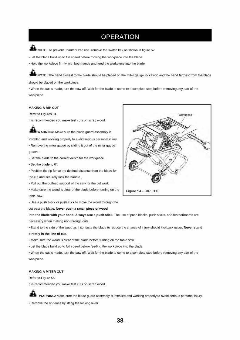
MAKING A RIP CUT
Refer to Figures 54.
It is recommended you make test cuts on scrap wood.
WARNING: Make sure the blade guard assembly is
installed and working properly to avoid serious personal injury.
• Remove the miter gauge by sliding it out of the miter gauge
groove.
• Set the blade to the correct depth for the workpiece.
• Set the blade to 0°.
• Position the rip fence the desired distance from the blade for
the cut and securely lock the handle.
• Pull out the outfeed support of the saw for the cut work.
• Make sure the wood is clear of the blade before turning on the
table saw.
• Use a push block or push stick to move the wood through the
cut past the blade. Never push a small piece of wood
into the blade with your hand. Always use a push stick. The use of push blocks, push sticks, and featherboards are
necessary when making non-through cuts.
• Stand to the side of the wood as it contacts the blade to reduce the chance of injury should kickback occur. Never stand
directly in the line of cut.
• Make sure the wood is clear of the blade before turning on the table saw.
• Let the blade build up to full speed before feeding the workpiece into the blade.
• When the cut is made, turn the saw off. Wait for the blade to come to a complete stop before removing any part of the
workpiece.
MAKING A MITER CUT
Refer to Figure 55
It is recommended you make test cuts on scrap wood.
WARNING: Make sure the blade guard assembly is installed and working properly to avoid serious personal injury.
• Remove the rip fence by lifting the locking lever.
OPERATION
Figure 54 - RIP CUT
_ 38 _
• Set the blade to the correct depth for the workpiece.
• Set the miter gauge to desired angle and tighten the lock knob.
• Pull out the outfeed support of the saw for the cut work.
• Make sure the wood is clear of the blade before turning on the
saw.
• Let the blade build up to full speed before moving the
workpiece into the blade.
• Hold the workpiece firmly with both hands and feed the
workpiece into the blade.
NOTE: The hand closest to the blade should be placed
on the miter gauge lock knob and the hand farthest from the
blade should be placed on the workpiece.
• When the cut is made, turn the saw off. Wait for the blade to
come to a complete stop before removing any part of the
workpiece.
CAUTION: The miter gauge cannot be used in the left miter gauge groove when bevel cutting due to blade guard
interference. Only use the miter gauge in the right miter gauge groove when bevel cutting.
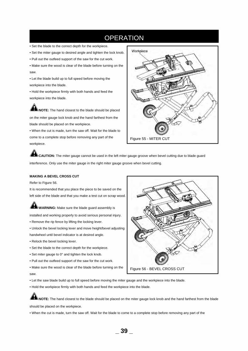
MAKING A BEVEL CROSS CUT
Refer to Figure 56.
It is recommended that you place the piece to be saved on the
left side of the blade and that you make a test cut on scrap wood.
WARNING: Make sure the blade guard assembly is
installed and working properly to avoid serious personal injury.
• Remove the rip fence by lifting the locking lever.
• Unlock the bevel locking lever and move height/bevel adjusting
handwheel until bevel indicator is at desired angle.
• Relock the bevel locking lever.
• Set the blade to the correct depth for the workpiece.
• Set miter gauge to 0° and tighten the lock knob.
• Pull out the outfeed support of the saw for the cut work.
• Make sure the wood is clear of the blade before turning on the
saw.
• Let the saw blade build up to full speed before moving the miter gauge and the workpiece into the blade.
• Hold the workpiece firmly with both hands and feed the workpiece into the blade.
NOTE: The hand closest to the blade should be placed on the miter gauge lock knob and the hand farthest from the blade
should be placed on the workpiece.
• When the cut is made, turn the saw off. Wait for the blade to come to a complete stop before removing any part of the
OPERATION
Figure 56 - BEVEL CROSS CUT
_ 39 _
Figure 55 - MITER CUT
workpiece.
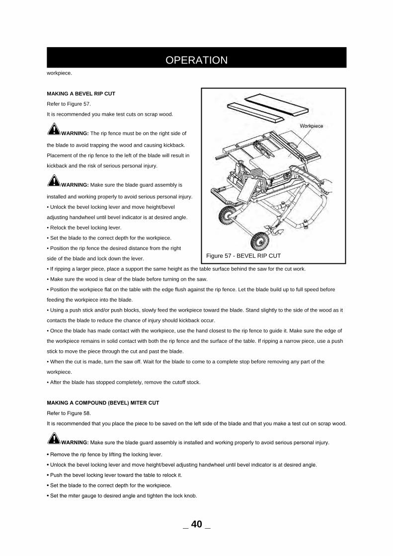
MAKING A BEVEL RIP CUT
Refer to Figure 57.
It is recommended you make test cuts on scrap wood.
WARNING: The rip fence must be on the right side of
the blade to avoid trapping the wood and causing kickback.
Placement of the rip fence to the left of the blade will result in
kickback and the risk of serious personal injury.
WARNING: Make sure the blade guard assembly is
installed and working properly to avoid serious personal injury.
• Unlock the bevel locking lever and move height/bevel
adjusting handwheel until bevel indicator is at desired angle.
• Relock the bevel locking lever.
• Set the blade to the correct depth for the workpiece.
• Position the rip fence the desired distance from the right
side of the blade and lock down the lever.
• If ripping a larger piece, place a support the same height as the table surface behind the saw for the cut work.
• Make sure the wood is clear of the blade before turning on the saw.
• Position the workpiece flat on the table with the edge flush against the rip fence. Let the blade build up to full speed before
feeding the workpiece into the blade.
• Using a push stick and/or push blocks, slowly feed the workpiece toward the blade. Stand slightly to the side of the wood as it
contacts the blade to reduce the chance of injury should kickback occur.
• Once the blade has made contact with the workpiece, use the hand closest to the rip fence to guide it. Make sure the edge of
the workpiece remains in solid contact with both the rip fence and the surface of the table. If ripping a narrow piece, use a push
stick to move the piece through the cut and past the blade.
• When the cut is made, turn the saw off. Wait for the blade to come to a complete stop before removing any part of the
workpiece.
• After the blade has stopped completely, remove the cutoff stock.
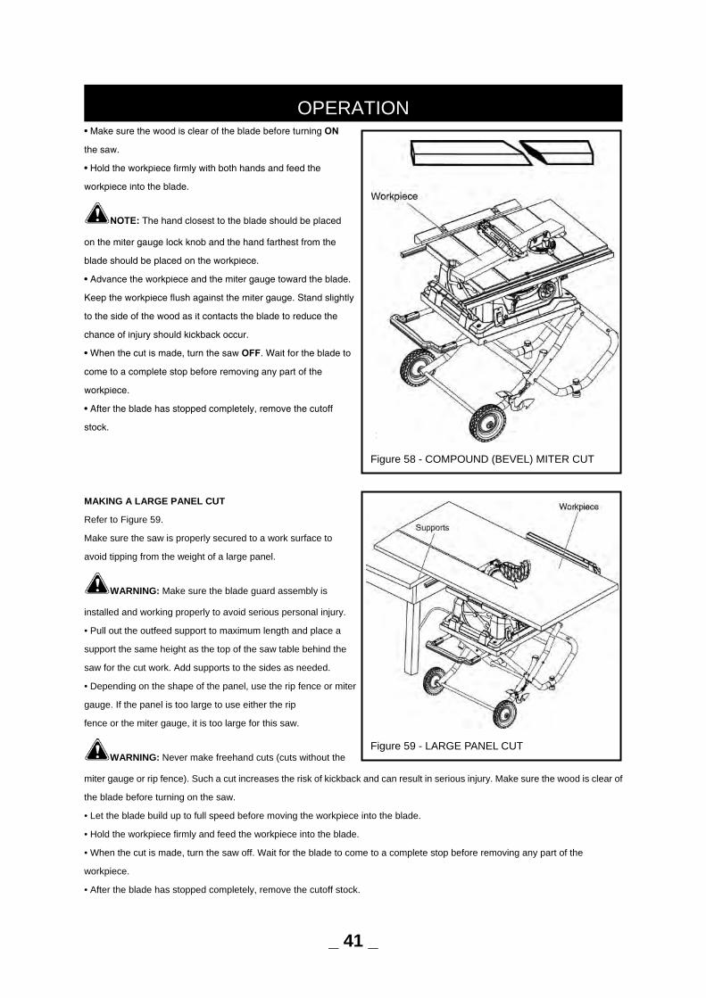
MAKING A COMPOUND (BEVEL) MITER CUT
Refer to Figure 58.
It is recommended that you place the piece to be saved on the left side of the blade and that you make a test cut on scrap wood.
WARNING: Make sure the blade guard assembly is installed and working properly to avoid serious personal injury.
• Remove the rip fence by lifting the locking lever.
• Unlock the bevel locking lever and move height/bevel adjusting handwheel until bevel indicator is at desired angle.
• Push the bevel locking lever toward the table to relock it.
• Set the blade to the correct depth for the workpiece.
• Set the miter gauge to desired angle and tighten the lock knob.
OPERATION
_ 40 _
Figure 57 - BEVEL RIP CUT
• Make sure the wood is clear of the blade before turning ON
the saw.
• Hold the workpiece firmly with both hands and feed the
workpiece into the blade.
NOTE: The hand closest to the blade should be placed
on the miter gauge lock knob and the hand farthest from the
blade should be placed on the workpiece.
• Advance the workpiece and the miter gauge toward the blade.
Keep the workpiece flush against the miter gauge. Stand slightly
to the side of the wood as it contacts the blade to reduce the
chance of injury should kickback occur.
• When the cut is made, turn the saw OFF. Wait for the blade to
come to a complete stop before removing any part of the
workpiece.
• After the blade has stopped completely, remove the cutoff
stock.
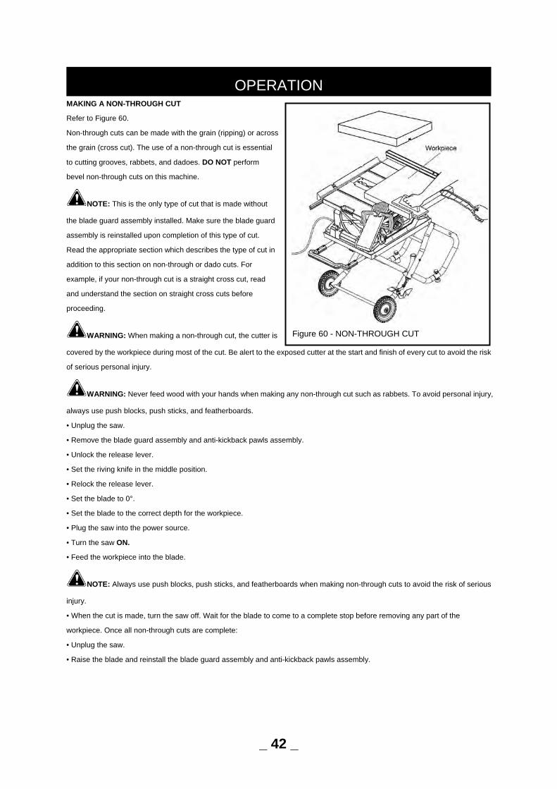
MAKING A LARGE PANEL CUT
Refer to Figure 59.
Make sure the saw is properly secured to a work surface to
avoid tipping from the weight of a large panel.
WARNING: Make sure the blade guard assembly is
installed and working properly to avoid serious personal injury.
• Pull out the outfeed support to maximum length and place a
support the same height as the top of the saw table behind the
saw for the cut work. Add supports to the sides as needed.
• Depending on the shape of the panel, use the rip fence or miter
gauge. If the panel is too large to use either the rip
fence or the miter gauge, it is too large for this saw.
WARNING: Never make freehand cuts (cuts without the
miter gauge or rip fence). Such a cut increases the risk of kickback and can result in serious injury. Make sure the wood is clear of
the blade before turning on the saw.
• Let the blade build up to full speed before moving the workpiece into the blade.
• Hold the workpiece firmly and feed the workpiece into the blade.
• When the cut is made, turn the saw off. Wait for the blade to come to a complete stop before removing any part of the
workpiece.
• After the blade has stopped completely, remove the cutoff stock.
OPERATION
Figure 58 - COMPOUND (BEVEL) MITER CUT
_ 41 _
Figure 59 - LARGE PANEL CUT
MAKING A NON-THROUGH CUT
Refer to Figure 60.
Non-through cuts can be made with the grain (ripping) or across
the grain (cross cut). The use of a non-through cut is essential
to cutting grooves, rabbets, and dadoes. DO NOT perform
bevel non-through cuts on this machine.
NOTE: This is the only type of cut that is made without
the blade guard assembly installed. Make sure the blade guard
assembly is reinstalled upon completion of this type of cut.
Read the appropriate section which describes the type of cut in
addition to this section on non-through or dado cuts. For
example, if your non-through cut is a straight cross cut, read
and understand the section on straight cross cuts before
proceeding.
WARNING: When making a non-through cut, the cutter is
covered by the workpiece during most of the cut. Be alert to the exposed cutter at the start and finish of every cut to avoid the risk
of serious personal injury.
WARNING: Never feed wood with your hands when making any non-through cut such as rabbets. To avoid personal injury,
always use push blocks, push sticks, and featherboards.
• Unplug the saw.
• Remove the blade guard assembly and anti-kickback pawls assembly.
• Unlock the release lever.
• Set the riving knife in the middle position.
• Relock the release lever.
• Set the blade to 0°.
• Set the blade to the correct depth for the workpiece.
• Plug the saw into the power source.
• Turn the saw ON.
• Feed the workpiece into the blade.
NOTE: Always use push blocks, push sticks, and featherboards when making non-through cuts to avoid the risk of serious
injury.
• When the cut is made, turn the saw off. Wait for the blade to come to a complete stop before removing any part of the
workpiece. Once all non-through cuts are complete:
• Unplug the saw.
• Raise the blade and reinstall the blade guard assembly and anti-kickback pawls assembly.
OPERATION
_ 42 _
Figure 60 - NON-THROUGH CUT
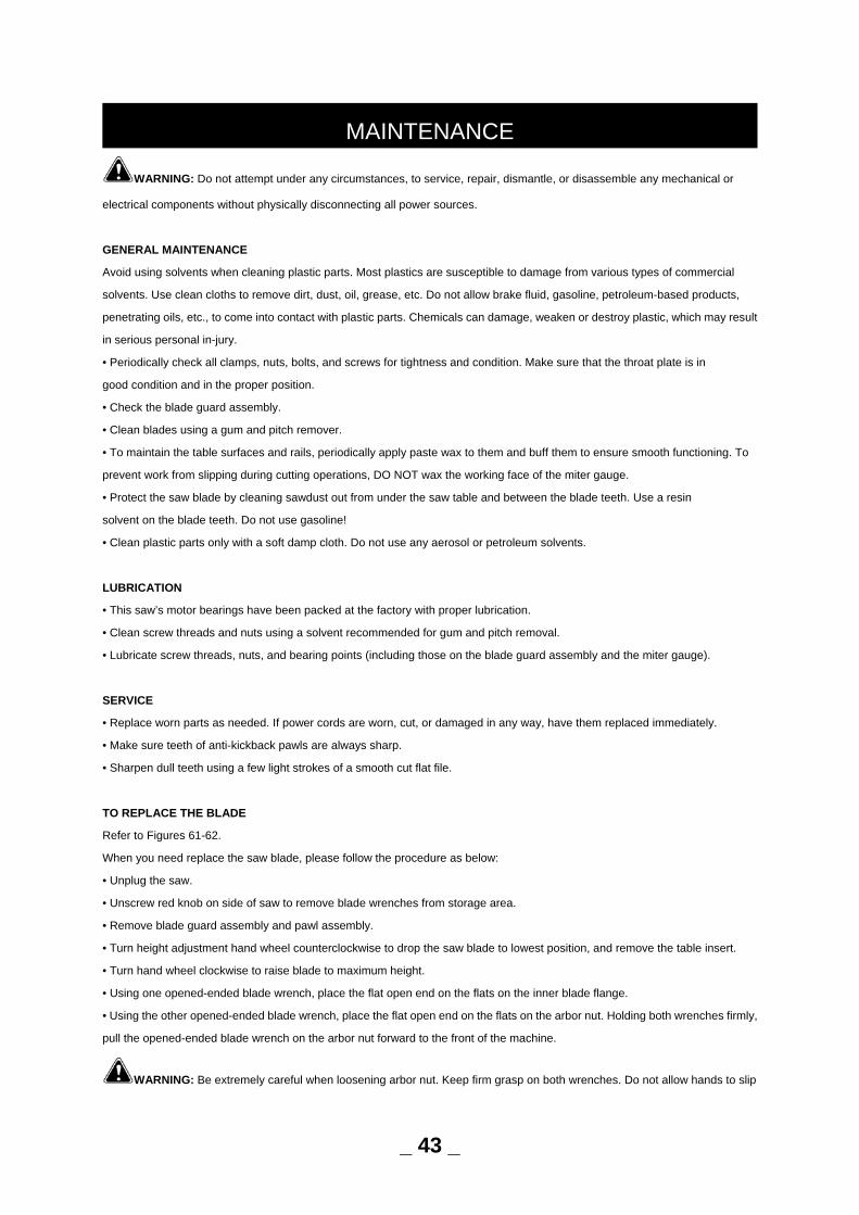
WARNING: Do not attempt under any circumstances, to service, repair, dismantle, or disassemble any mechanical or
electrical components without physically disconnecting all power sources.
GENERAL MAINTENANCE
Avoid using solvents when cleaning plastic parts. Most plastics are susceptible to damage from various types of commercial
solvents. Use clean cloths to remove dirt, dust, oil, grease, etc. Do not allow brake fluid, gasoline, petroleum-based products,
penetrating oils, etc., to come into contact with plastic parts. Chemicals can damage, weaken or destroy plastic, which may result
in serious personal in-jury.
• Periodically check all clamps, nuts, bolts, and screws for tightness and condition. Make sure that the throat plate is in
good condition and in the proper position.
• Check the blade guard assembly.
• Clean blades using a gum and pitch remover.
• To maintain the table surfaces and rails, periodically apply paste wax to them and buff them to ensure smooth functioning. To
prevent work from slipping during cutting operations, DO NOT wax the working face of the miter gauge.
• Protect the saw blade by cleaning sawdust out from under the saw table and between the blade teeth. Use a resin
solvent on the blade teeth. Do not use gasoline!
• Clean plastic parts only with a soft damp cloth. Do not use any aerosol or petroleum solvents.
LUBRICATION
• This saw’s motor bearings have been packed at the factory with proper lubrication.
• Clean screw threads and nuts using a solvent recommended for gum and pitch removal.
• Lubricate screw threads, nuts, and bearing points (including those on the blade guard assembly and the miter gauge).
SERVICE
• Replace worn parts as needed. If power cords are worn, cut, or damaged in any way, have them replaced immediately.
• Make sure teeth of anti-kickback pawls are always sharp.
• Sharpen dull teeth using a few light strokes of a smooth cut flat file.
TO REPLACE THE BLADE
Refer to Figures 61-62.
When you need replace the saw blade, please follow the procedure as below:
• Unplug the saw.
• Unscrew red knob on side of saw to remove blade wrenches from storage area.
• Remove blade guard assembly and pawl assembly.
• Turn height adjustment hand wheel counterclockwise to drop the saw blade to lowest position, and remove the table insert.
• Turn hand wheel clockwise to raise blade to maximum height.
• Using one opened-ended blade wrench, place the flat open end on the flats on the inner blade flange.
• Using the other opened-ended blade wrench, place the flat open end on the flats on the arbor nut. Holding both wrenches firmly,
pull the opened-ended blade wrench on the arbor nut forward to the front of the machine.
WARNING: Be extremely careful when loosening arbor nut. Keep firm grasp on both wrenches. Do not allow hands to slip
MAINTENANCE
_ 43 _
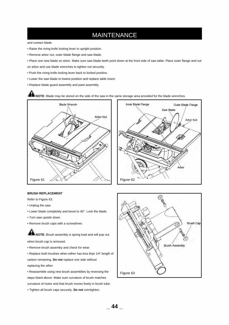
and contact blade.
• Raise the riving knife locking lever to upright position.
• Remove arbor nut, outer blade flange and saw blade.
• Place one new blade on arbor. Make sure saw blade teeth point down at the front side of saw table. Place outer flange and nut
on arbor and use blade wrenches to tighten nut securely.
• Push the riving knife locking lever back to locked position.
• Lower the saw blade to lowest position and replace table insert.
• Replace blade guard assembly and pawl assembly.
NOTE: Blade may be stored on the side of the saw in the same storage area provided for the blade wrenches.
BRUSH REPLACEMENT
Refer to Figure 63.
• Unplug the saw.
• Lower blade completely and bevel to 45°. Lock the blade.
• Turn saw upside down.
• Remove brush caps with a screwdriver.
NOTE: Brush assembly is spring load and will pop out
when brush cap is removed.
• Remove brush assemby and check for wear.
• Replace both brushes when either has less than 1⁄4” length of
carbon remaining. Do not replace one side without
replacing the other.
• Reassemble using new brush assemblies by reversing the
steps listed above. Make sure curvature of brush matches
curvature of motor and that brush moves freely in brush tube.
• Tighten all brush caps securely. Do not overtighten.
MAINTENANCE
Figure 62 Figure 61
Figure 63
_ 44 _
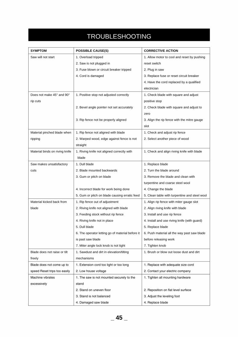
SYMPTOM POSSIBLE CAUSE(S) CORRECTIVE ACTION
Saw will not start 1. Overload tripped
2. Saw is not plugged in
3. Fuse blown or circuit breaker tripped
4. Cord is damaged
1. Allow motor to cool and reset by pushing
reset switch
2. Plug in saw
3. Replace fuse or reset circuit breaker
4. Have the cord replaced by a qualified
electrician
Does not make 45° and 90°
rip cuts
1. Positive stop not adjusted correctly
2. Bevel angle pointer not set accurately
3. Rip fence not be properly aligned
1. Check blade with square and adjust
positive stop
2. Check blade with square and adjust to
zero
3. Align the rip fence with the mitre gauge
slot
Material pinched blade when
ripping
1. Rip fence not aligned with blade
2. Warped wood, edge against fence is not
straight
1. Check and adjust rip fence
2. Select another piece of wood
Material binds on riving knife 1. Riving knife not aligned correctly with
blade
1. Check and align riving knife with blade
Saw makes unsatisfactory
cuts
1. Dull blade
2. Blade mounted backwards
3. Gum or pitch on blade
4. Incorrect blade for work being done
5. Gum or pitch on blade causing erratic feed
1. Replace blade
2. Turn the blade around
3. Remove the blade and clean with
turpentine and coarse steel wool
4. Change the blade
5. Clean table with turpentine and steel wool
Material kicked back from
blade
1. Rip fence out of adjustment
2. Riving knife not aligned with blade
3. Feeding stock without rip fence
4. Riving knife not in place
5. Dull blade
6. The operator letting go of material before it
is past saw blade
7. Miter angle lock knob is not tight
1. Align rip fence with miter gauge slot
2. Align riving knife with blade
3. Install and use rip fence
4. Install and use riving knife (with guard)
5. Replace blade
6. Push material all the way past saw blade
before releasing work
7. Tighten knob
Blade does not raise or tilt
freely
1. Sawdust and dirt in elevation/tilting
mechanisms
1. Brush or blow out loose dust and dirt
Blade does not come up to
speed Reset trips too easily
1. Extension cord too light or too long
2. Low house voltage
1. Replace with adequate size cord
2. Contact your electric company
Machine vibrates
excessively
1. The saw is not mounted securely to the
stand
2. Stand on uneven floor
3. Stand is not balanced
4. Damaged saw blade
1. Tighten all mounting hardware
2. Reposition on flat level surfece
3. Adjust the leveling foot
4. Replace blade
TROUBLESHOOTING
_ 45 _
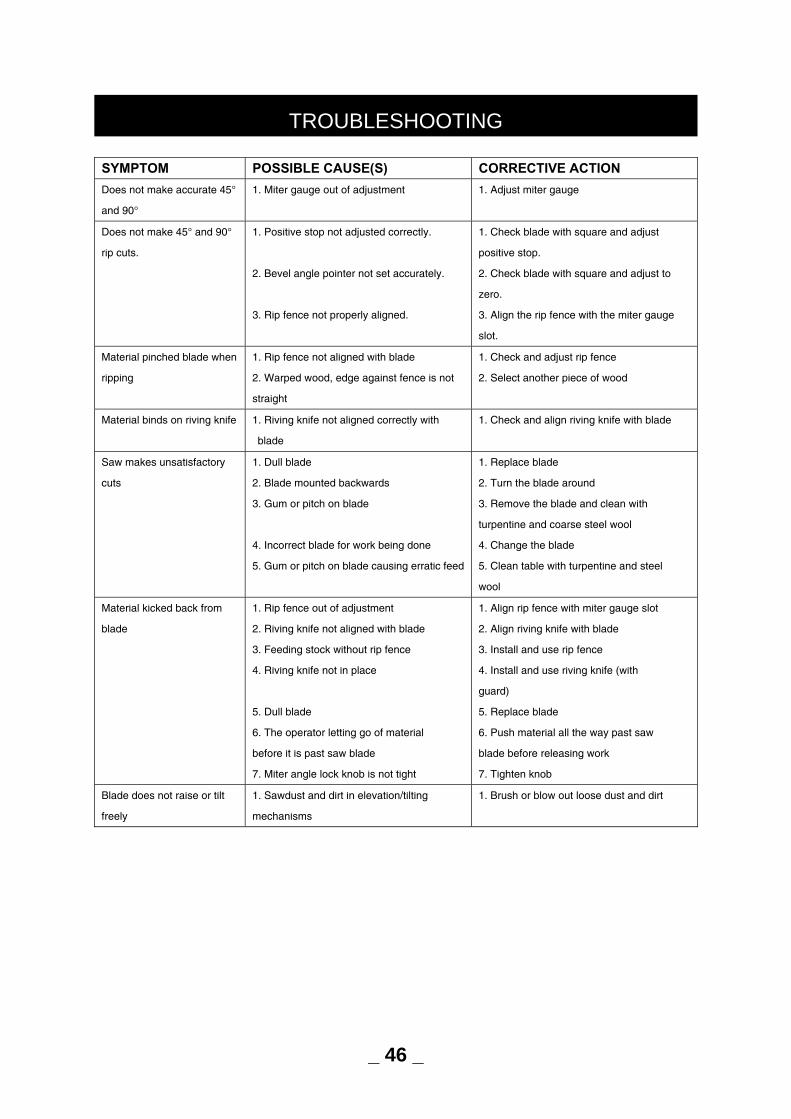
SYMPTOM POSSIBLE CAUSE(S) CORRECTIVE ACTION
Does not make accurate 45°
and 90°
1. Miter gauge out of adjustment 1. Adjust miter gauge
Does not make 45° and 90°
rip cuts.
1. Positive stop not adjusted correctly.
2. Bevel angle pointer not set accurately.
3. Rip fence not properly aligned.
1. Check blade with square and adjust
positive stop.
2. Check blade with square and adjust to
zero.
3. Align the rip fence with the miter gauge
slot.
Material pinched blade when
ripping
1. Rip fence not aligned with blade
2. Warped wood, edge against fence is not
straight
1. Check and adjust rip fence
2. Select another piece of wood
Material binds on riving knife 1. Riving knife not aligned correctly with
blade
1. Check and align riving knife with blade
Saw makes unsatisfactory
cuts
1. Dull blade
2. Blade mounted backwards
3. Gum or pitch on blade
4. Incorrect blade for work being done
5. Gum or pitch on blade causing erratic feed
1. Replace blade
2. Turn the blade around
3. Remove the blade and clean with
turpentine and coarse steel wool
4. Change the blade
5. Clean table with turpentine and steel
wool
Material kicked back from
blade
1. Rip fence out of adjustment
2. Riving knife not aligned with blade
3. Feeding stock without rip fence
4. Riving knife not in place
5. Dull blade
6. The operator letting go of material
before it is past saw blade
7. Miter angle lock knob is not tight
1. Align rip fence with miter gauge slot
2. Align riving knife with blade
3. Install and use rip fence
4. Install and use riving knife (with
guard)
5. Replace blade
6. Push material all the way past saw
blade before releasing work
7. Tighten knob
Blade does not raise or tilt
freely
1. Sawdust and dirt in elevation/tilting
mechanisms
1. Brush or blow out loose dust and dirt
TROUBLESHOOTING
_ 46 _

For questions / comments, technical assistance or repair parts - Please call toll free at: 1-877-684-8912 (Monday - Friday 8am -
6pm EST.)
PART DESCRIPTION PART#
A Blade guard assembly 2403605001
B Anti-kickback Pawl Assembly 2403605002
C Miter Gauge Assembly 2403605003
D Rip Fence Assembly 2403605004
E Dust Extraction Port 2403605005
F Push Stick 2403605006
G Blade wrench 2403605007
H Locking knob 2403605008
I Wheel 2403605009
J Locking Knob 2403605010
K Shock Absorption Pad 2403605011
L Leveling Foot Assembly 2403605012
M Roller Sleeve 2403605013
N Handwheel 2403605014
O Handle 2403605015
P Safety key 2403605016
Q Saw blade 2403605017
R Blade nut 2403605018
_ 47 _
REPLACEMENT PARTS LIST
Figure 64 - REPLACEMENT PARTS

TWO-YEAR LIMITED WARRANTY:
If, during normal use, this PERFORMAX® power tool breaks or fails due to a defect in material or workmanship within two years
from the date of original purchase, simply bring this tool with the original sales receipt back to your nearest Menards® retail store.
At its discretion, PERFORMAX® agrees to have the tool or any defective part(s) repaired or replaced with the same or similar
PERFORMAX® product or part free of charge, within the stated warranty period, when returned by the original purchaser with
original sales receipt. This warranty; (1) excludes expendable parts; (2) shall be void if this tool is used for commercial and/or
rental purposes; and (3) does not cover any losses, injuries to persons/property or costs. This warranty does give you specific
legal rights and you may have other rights, which vary from state to state.
WARRANTY
_ 48 _