Embed Size (px)
Citation preview
PREPARED BY K. MANOKARAN, LEAD AUDITOR, DNVPREPARED BY K. MANOKARAN, LEAD AUDITOR, DNV Page: 1
ENERGY MANAGEMENT
����������� �
��������������� � ���������������
PREPARED BY K. MANOKARAN, LEAD AUDITOR, DNVPREPARED BY K. MANOKARAN, LEAD AUDITOR, DNV Page: 2
ENERGY MANAGEMENT
����������������� !��
PREPARED BY K. MANOKARAN, LEAD AUDITOR, DNVPREPARED BY K. MANOKARAN, LEAD AUDITOR, DNV Page: 3
ENERGY MANAGEMENT
��!��!"#������������� !��
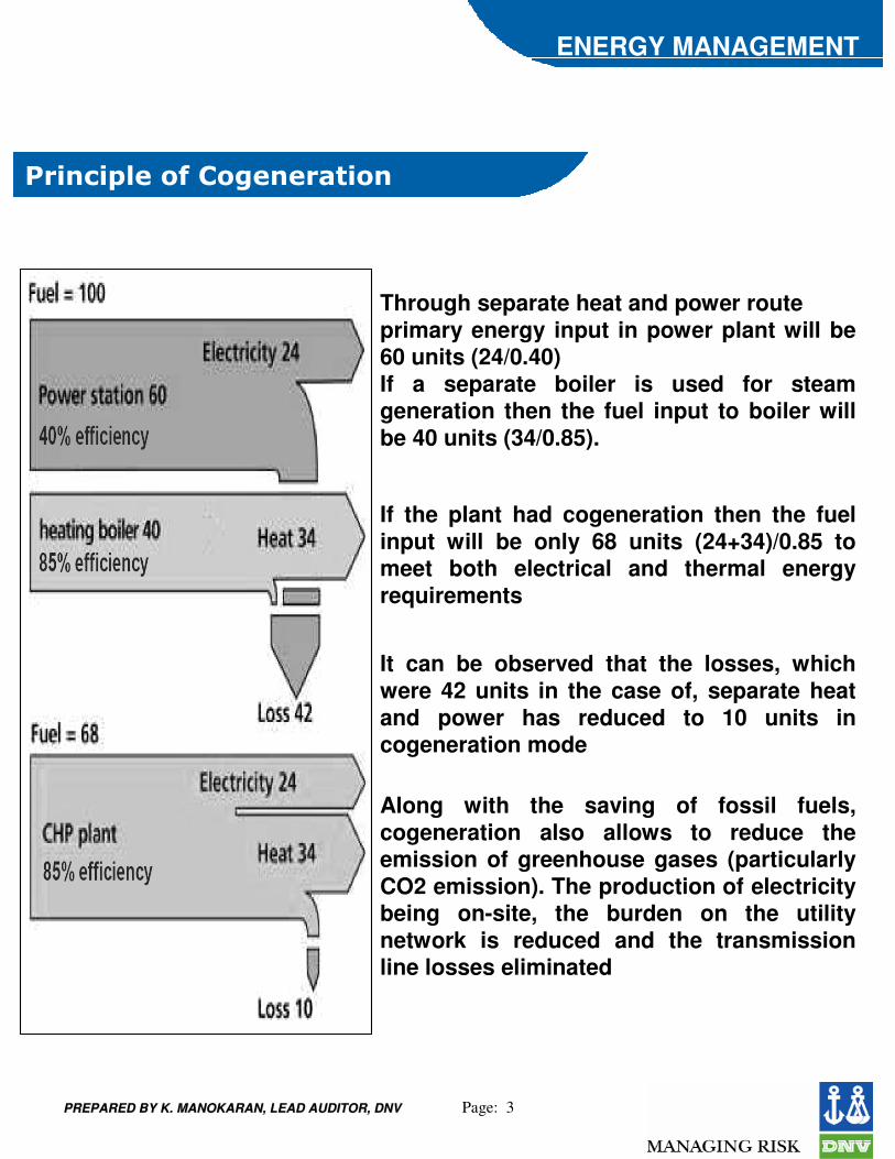
Through separate heat and power routeprimary energy input in power plant will be 60 units (24/0.40) If a separate boiler is used for steam generation then the fuel input to boiler will be 40 units (34/0.85).
If the plant had cogeneration then the fuel input will be only 68 units (24+34)/0.85 to meet both electrical and thermal energy requirements
It can be observed that the losses, which were 42 units in the case of, separate heat and power has reduced to 10 units in cogeneration mode
Along with the saving of fossil fuels, cogeneration also allows to reduce the emission of greenhouse gases (particularly CO2 emission). The production of electricity being on-site, the burden on the utility network is reduced and the transmission line losses eliminated
PREPARED BY K. MANOKARAN, LEAD AUDITOR, DNVPREPARED BY K. MANOKARAN, LEAD AUDITOR, DNV Page: 4
ENERGY MANAGEMENT
���$�!��#��" !��%������������� !���
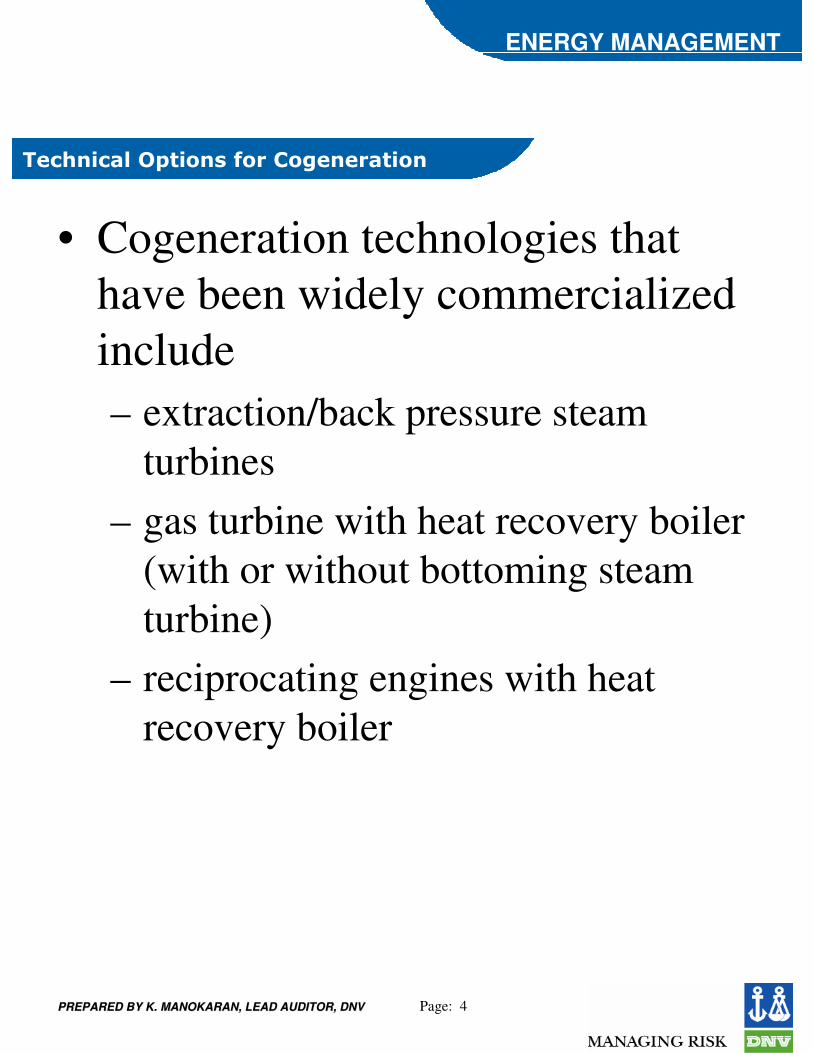
• Cogeneration technologies that have been widely commercialized include – extraction/back pressure steam
turbines– gas turbine with heat recovery boiler
(with or without bottoming steam turbine)
– reciprocating engines with heat recovery boiler

PREPARED BY K. MANOKARAN, LEAD AUDITOR, DNVPREPARED BY K. MANOKARAN, LEAD AUDITOR, DNV Page: 5
ENERGY MANAGEMENT
� ��&� '�(!����������� !���%)% �&%�
PREPARED BY K. MANOKARAN, LEAD AUDITOR, DNVPREPARED BY K. MANOKARAN, LEAD AUDITOR, DNV Page: 6
ENERGY MANAGEMENT
� ��&� '�(!����������� !������ '��%
• The choice between backpressure turbine and extraction-condensing turbine depends mainly on the quantities of power and heat, quality of heat, and economic factors
• option for using a wide variety of conventional as well as alternative fuels such as coal, natural gas, fuel oil and biomass
• power generation efficiency of the cycle may be sacrificed to some extent in order to optimize heat supply
• In backpressure cogeneration plants, there is no need for large cooling towers
• Steam turbines are mostly used where the demand for electricity is greater than one MW up to a few hundreds of MW
• Due to the system inertia, their operation is not suitable for sites with intermittent energy demand
PREPARED BY K. MANOKARAN, LEAD AUDITOR, DNVPREPARED BY K. MANOKARAN, LEAD AUDITOR, DNV Page: 7
ENERGY MANAGEMENT
��%� '�(!����������� !���%)% �&%�
PREPARED BY K. MANOKARAN, LEAD AUDITOR, DNVPREPARED BY K. MANOKARAN, LEAD AUDITOR, DNV Page: 8
ENERGY MANAGEMENT
��%� '�(!����������� !������ '��%
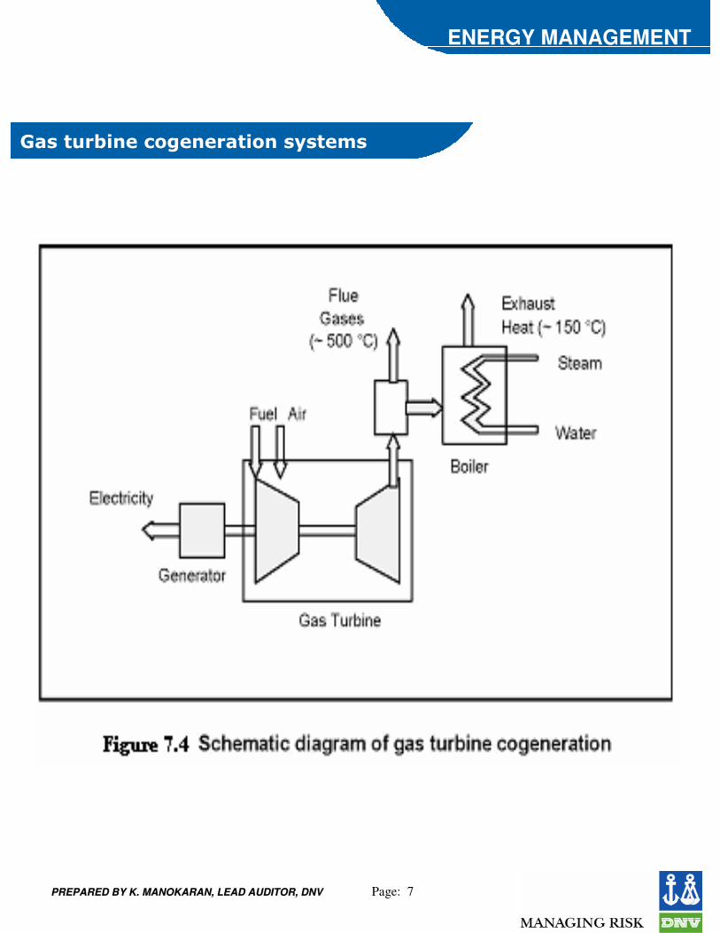
• Natural gas is most commonly used; other fuels such as light fuel oil or diesel can also be employed
• The typical range of gas turbines varies from a fraction of a MW to around 100 MW
• the gestation period for developing a project is shorter and the equipment can be delivered in a modular manner
• Gas turbine has a short start-up time and provides the flexibility of intermittent operation
• If the heat output is less than that required by the user, it is possible to have supplementary natural gas firing
• if more power is required at the site, it is possible to adopt a combined cycle that is a combination of gas turbine and steam turbine cogeneration
PREPARED BY K. MANOKARAN, LEAD AUDITOR, DNVPREPARED BY K. MANOKARAN, LEAD AUDITOR, DNV Page: 9
ENERGY MANAGEMENT
��!"���� !������!����������� !���%)% �&%
PREPARED BY K. MANOKARAN, LEAD AUDITOR, DNVPREPARED BY K. MANOKARAN, LEAD AUDITOR, DNV Page: 10
ENERGY MANAGEMENT
��!"���� !������!����������� !������ '��%�
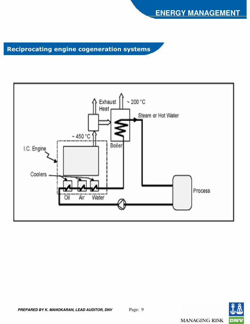
• high power generation efficiencies in comparison with other prime movers
• There are two sources of heat for recovery: exhaust gas at high temperature and engine jacket cooling water system at low temperature
• more popular with smaller energy consuming facilities, particularly those having a greater need for electricity than thermal energy
• diesel has been the most common fuel in the past, the prime movers can also operate with heavy fuel oil or natural gas
• ideal for intermittent operation and their performance is not as sensitive to the changes in ambient temperatures as the gas turbines
• Though the initial investment on these machines is low, their operating and maintenance costs are high due to high wear and tear
PREPARED BY K. MANOKARAN, LEAD AUDITOR, DNVPREPARED BY K. MANOKARAN, LEAD AUDITOR, DNV Page: 11
ENERGY MANAGEMENT
�#�%%!�!�� !�������������� !����)% �&%�
• A cogeneration system can be classified as either a topping or a bottoming cycle on the basis of the sequence of energy use
• In a topping cycle, the fuel supplied is used to first produce power and then thermal energy, which is the by-product of the cycle and is used to satisfy process heat or other thermal requirements
• In a bottoming cycle, the primary fuel produces high temperature thermal energy and the heat rejected from the process is used to generate power through a recovery boiler and a turbine generator
PREPARED BY K. MANOKARAN, LEAD AUDITOR, DNVPREPARED BY K. MANOKARAN, LEAD AUDITOR, DNV Page: 12
ENERGY MANAGEMENT
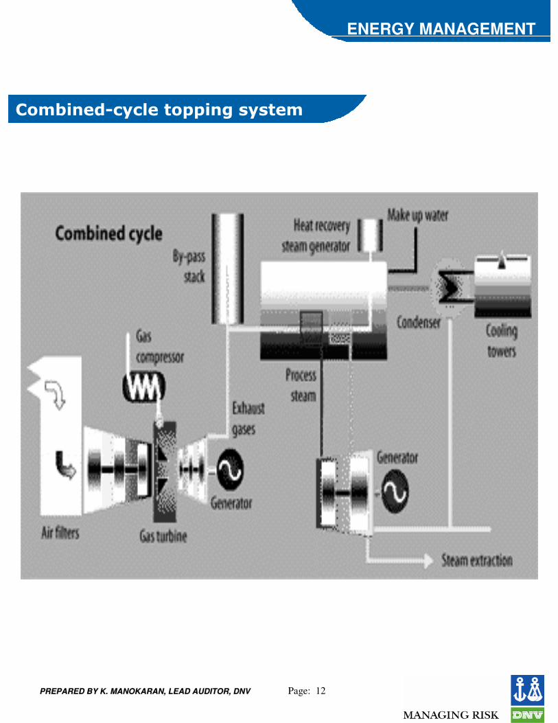
��&(!���*�)�#�� �""!���%)% �&
PREPARED BY K. MANOKARAN, LEAD AUDITOR, DNVPREPARED BY K. MANOKARAN, LEAD AUDITOR, DNV Page: 13
ENERGY MANAGEMENT
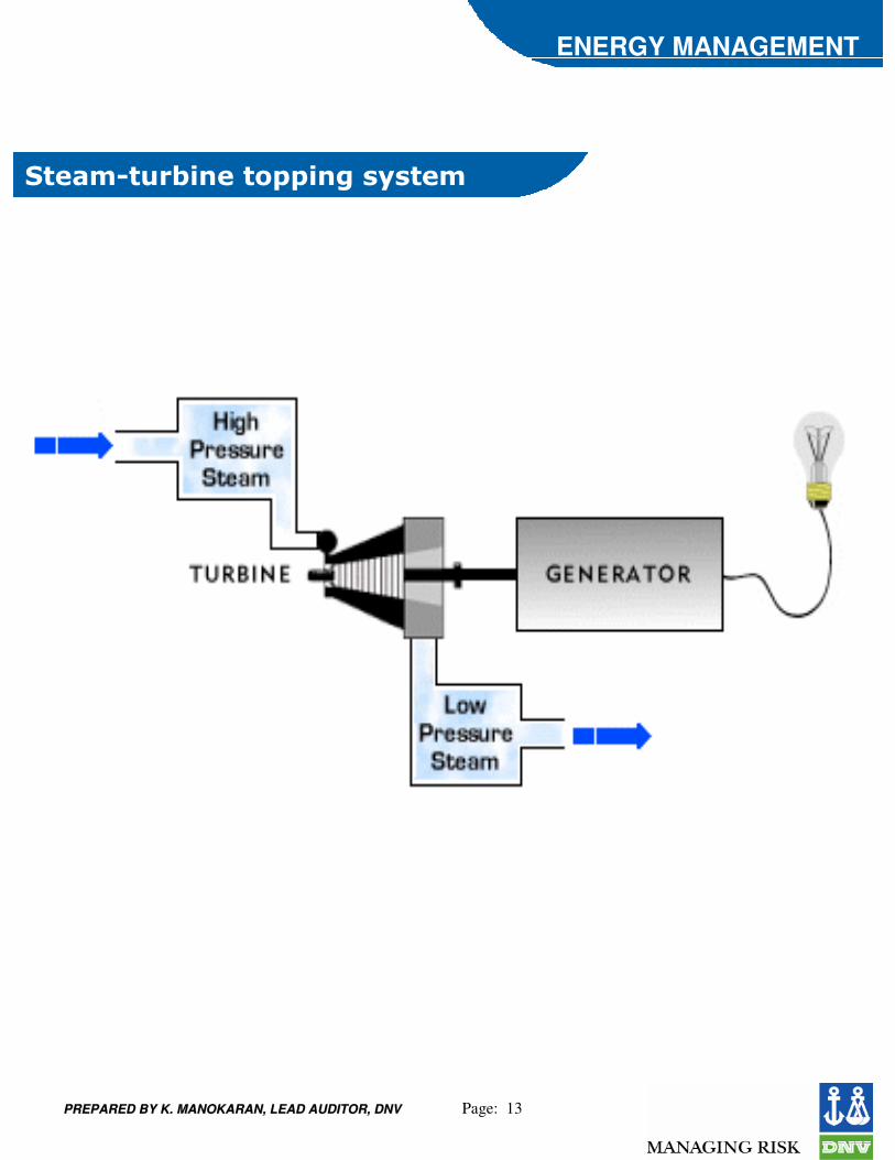
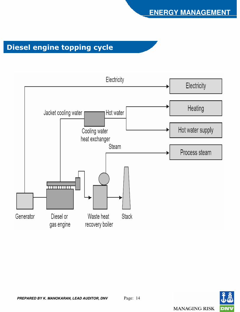
� ��&* '�(!��� �""!���%)% �&
PREPARED BY K. MANOKARAN, LEAD AUDITOR, DNVPREPARED BY K. MANOKARAN, LEAD AUDITOR, DNV Page: 14
ENERGY MANAGEMENT
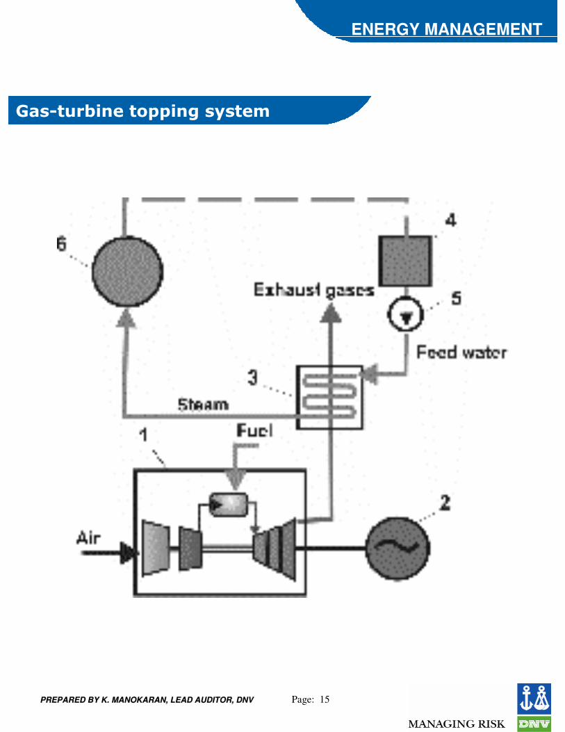
+!�%�#����!��� �""!����)�#�
PREPARED BY K. MANOKARAN, LEAD AUDITOR, DNVPREPARED BY K. MANOKARAN, LEAD AUDITOR, DNV Page: 15
ENERGY MANAGEMENT
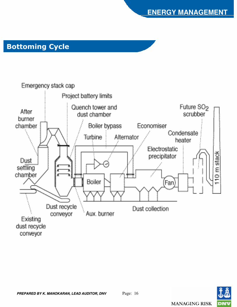
��%* '�(!��� �""!���%)% �&
PREPARED BY K. MANOKARAN, LEAD AUDITOR, DNVPREPARED BY K. MANOKARAN, LEAD AUDITOR, DNV Page: 16
ENERGY MANAGEMENT
�� �&!����)�#�
PREPARED BY K. MANOKARAN, LEAD AUDITOR, DNVPREPARED BY K. MANOKARAN, LEAD AUDITOR, DNV Page: 17
ENERGY MANAGEMENT
,�� ��%� ��#'���!����������� !����$�!���
• the cogeneration plant is sized to meet the minimum electricity demand of the site based on the historical demand curve
• rest of the needed power is purchased from the utility grid
• thermal energy requirement of the site could be met by the cogeneration system alone or by additional boilers
• If the thermal energy generated with the base electrical load exceeds the plant’s demand and if the situation permits, excess thermal energy can be exported to neighbouring customers
��%���#�� �!��#�#����&� �$!���
PREPARED BY K. MANOKARAN, LEAD AUDITOR, DNVPREPARED BY K. MANOKARAN, LEAD AUDITOR, DNV Page: 18
ENERGY MANAGEMENT
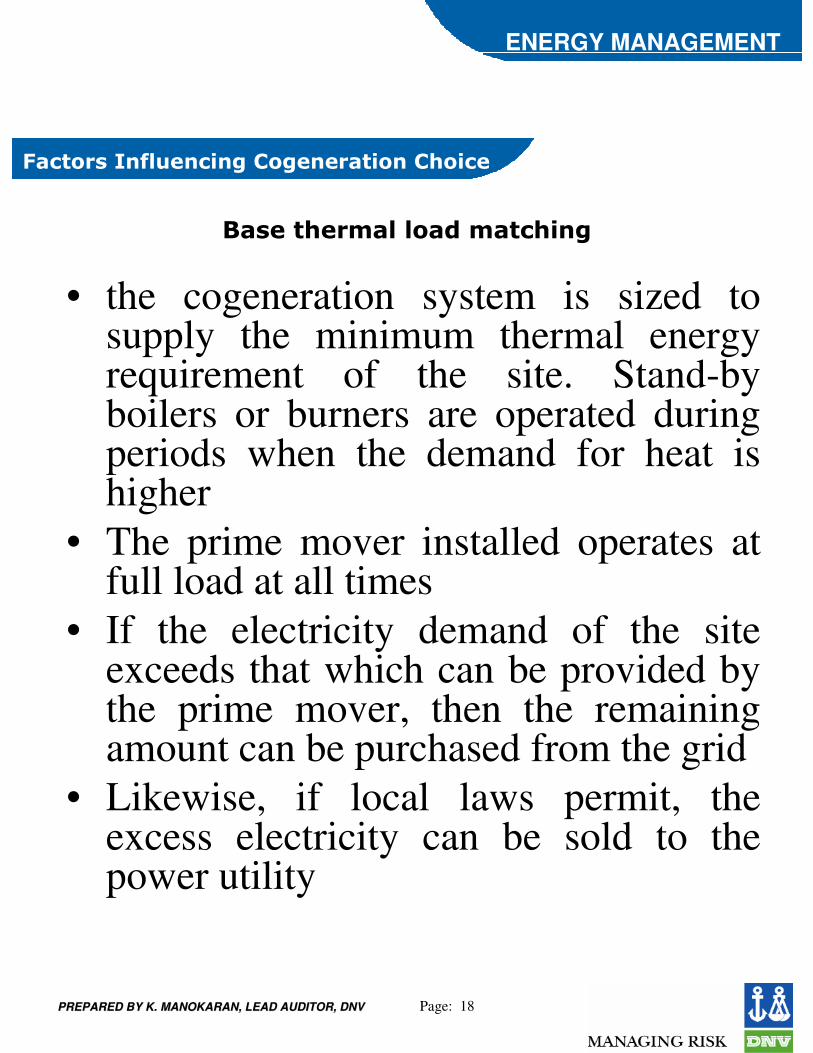
��%�� $��&�#�#����&� �$!��
• the cogeneration system is sized to supply the minimum thermal energy requirement of the site. Stand-by boilers or burners are operated during periods when the demand for heat is higher
• The prime mover installed operates at full load at all times
• If the electricity demand of the site exceeds that which can be provided by the prime mover, then the remaining amount can be purchased from the grid
• Likewise, if local laws permit, the excess electricity can be sold to the power utility
,�� ��%� ��#'���!����������� !����$�!���

PREPARED BY K. MANOKARAN, LEAD AUDITOR, DNVPREPARED BY K. MANOKARAN, LEAD AUDITOR, DNV Page: 19
ENERGY MANAGEMENT
�#�� �!��#�#����&� �$!���
• the facility is totally independent of the power utility grid
• All the power requirements of the site, including the reserves needed during scheduled and unscheduled maintenance, are to be taken into account while sizing the system
• This is also referred to as a “stand-alone” system• If the thermal energy demand of the site is higher
than that generated by the cogeneration system, auxiliary boilers are used
• On the other hand, when the thermal energy demand is low, some thermal energy is wasted
• If there is a possibility, excess thermal energy can be exported to neighbouring facilities
,�� ��%� ��#'���!����������� !����$�!���
PREPARED BY K. MANOKARAN, LEAD AUDITOR, DNVPREPARED BY K. MANOKARAN, LEAD AUDITOR, DNV Page: 20
ENERGY MANAGEMENT
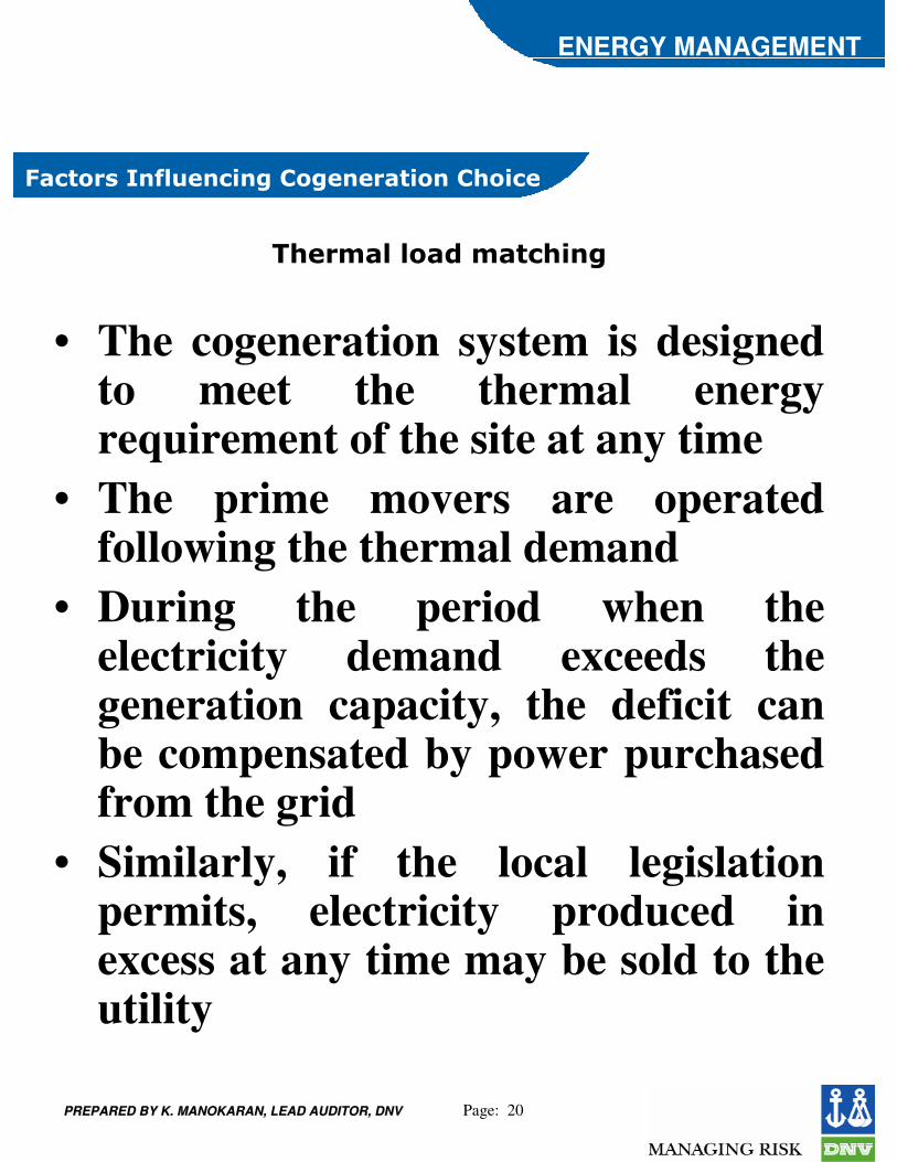
�$��&�#�#����&� �$!���
• The cogeneration system is designed to meet the thermal energy requirement of the site at any time
• The prime movers are operated following the thermal demand
• During the period when the electricity demand exceeds the generation capacity, the deficit can be compensated by power purchased from the grid
• Similarly, if the local legislation permits, electricity produced in excess at any time may be sold to the utility
,�� ��%� ��#'���!����������� !����$�!���
PREPARED BY K. MANOKARAN, LEAD AUDITOR, DNVPREPARED BY K. MANOKARAN, LEAD AUDITOR, DNV Page: 21
ENERGY MANAGEMENT
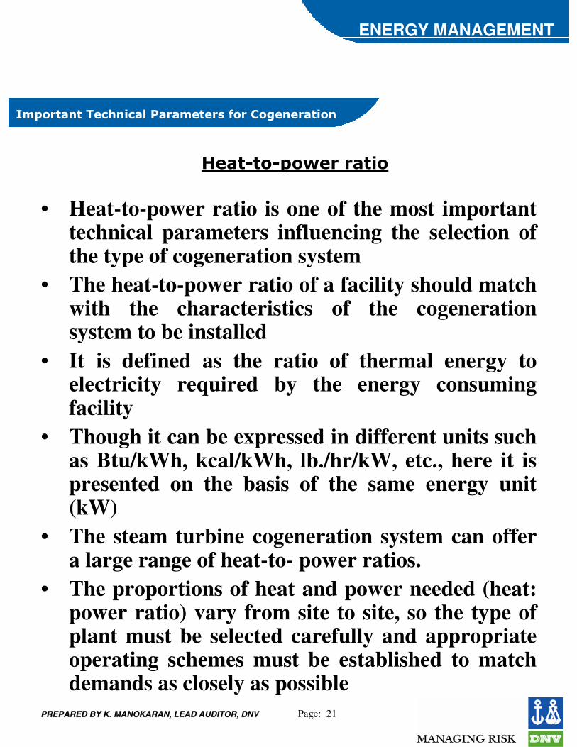
&"�� �� ����$�!��#�����&� ��%������������� !���
• Heat-to-power ratio is one of the most important technical parameters influencing the selection of the type of cogeneration system
• The heat-to-power ratio of a facility should match with the characteristics of the cogeneration system to be installed
• It is defined as the ratio of thermal energy to electricity required by the energy consuming facility
• Though it can be expressed in different units such as Btu/kWh, kcal/kWh, lb./hr/kW, etc., here it is presented on the basis of the same energy unit (kW)
• The steam turbine cogeneration system can offer a large range of heat-to- power ratios.
• The proportions of heat and power needed (heat: power ratio) vary from site to site, so the type of plant must be selected carefully and appropriate operating schemes must be established to match demands as closely as possible
��� * �*"�-����� !��
PREPARED BY K. MANOKARAN, LEAD AUDITOR, DNVPREPARED BY K. MANOKARAN, LEAD AUDITOR, DNV Page: 22
ENERGY MANAGEMENT
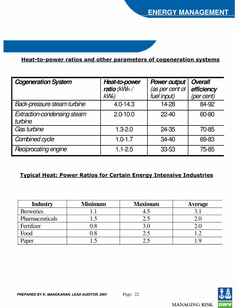
��� * �*"�-����� !�%������ $���"���&� ��%������������ !���%)% �&%
Cogeneration System Heat-to-power ratio (kWth / kWe)
Power output (as per cent of fuel input)
Overall efficiency (per cent)
Back-pressure steam turbine 4.0-14.3 14-28 84-92
Extraction-condensing steam turbine
2.0-10.0 22-40 60-80
Gas turbine 1.3-2.0 24-35 70-85 Combined cycle 1.0-1.7 34-40 69-83 Reciprocating engine 1.1-2.5 33-53 75-85
�)"!��#���� .���-���� !�%�������� �!�������)� � ��%!/�� ��'% �!�%�
Industry Minimum Maximum Average Breweries 1.1 4.5 3.1 Pharmaceuticals 1.5 2.5 2.0 Fertilizer 0.8 3.0 2.0 Food 0.8 2.5 1.2 Paper 1.5 2.5 1.9
PREPARED BY K. MANOKARAN, LEAD AUDITOR, DNVPREPARED BY K. MANOKARAN, LEAD AUDITOR, DNV Page: 23
ENERGY MANAGEMENT
�������� !��!%�#!0�#)� ��(��&�% �� ��� !/�!�
• The demand for both steam and power is balanced i.e. consistent with the range of steam: power output ratios that can be obtained from a suitable cogeneration plant.
• A single plant or group of plants has sufficient demand for steam and power to permit economies of scale to be achieved.
• Peaks and troughs in demand can be managed or, in the case of electricity, adequate backup supplies can be obtained from the utility company

PREPARED BY K. MANOKARAN, LEAD AUDITOR, DNVPREPARED BY K. MANOKARAN, LEAD AUDITOR, DNV Page: 24
ENERGY MANAGEMENT
1'�#! )���� $��&�#������)��������
• The quality of thermal energy required (temperature and pressure) also determines the type of cogeneration system
• For a sugar mill needing thermal energy at about 120°C, a topping cycle cogeneration system can meet the heat demand
• On the other hand, for a cement plant requiring thermal energy at about 1450°C, a bottoming cycle cogeneration system can meet both high quality thermal energy and electricity demands of the plant
PREPARED BY K. MANOKARAN, LEAD AUDITOR, DNVPREPARED BY K. MANOKARAN, LEAD AUDITOR, DNV Page: 25
ENERGY MANAGEMENT
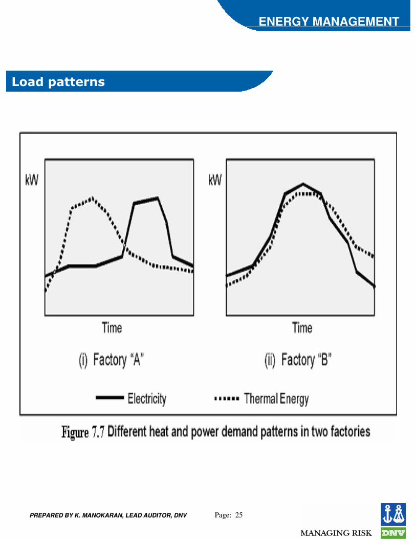
2����"� ���%�
PREPARED BY K. MANOKARAN, LEAD AUDITOR, DNVPREPARED BY K. MANOKARAN, LEAD AUDITOR, DNV Page: 26
ENERGY MANAGEMENT
,'�#%��/�!#�(#��
• Depending on the availability of fuels, some potential cogeneration systems may have to be rejected
• The availability of cheap fuels or waste products that can be used as fuels at a site is one of the major factors in the technical consideration because it determines the competitiveness of the cogeneration system.
• A rice mill needs mechanical power for milling and heat for paddy drying.
• If a cogeneration system were considered, the steam turbine system would be the first priority because it can use the rice husk as the fuel, which is available as waste product from the mill.
PREPARED BY K. MANOKARAN, LEAD AUDITOR, DNVPREPARED BY K. MANOKARAN, LEAD AUDITOR, DNV Page: 27
ENERGY MANAGEMENT
�)% �&���#!�(!#! )�
• Some energy consuming facilities require very reliable power and/or heat
• for instance, a pulp and paper industry cannot operate with a prolonged unavailability of process steam
• In such instances, the cogeneration system to be installed must be modular, i.e. it should consist of more than one unit so that shut down of a specific unit cannot seriously affect the energy supply

PREPARED BY K. MANOKARAN, LEAD AUDITOR, DNVPREPARED BY K. MANOKARAN, LEAD AUDITOR, DNV Page: 28
ENERGY MANAGEMENT
��!����"����� �%)% �&�/��%'%�!���"����� �%)% �&�
• A grid-dependent system has access to the grid to buy or sell electricity
• The grid-independent system is also known as a “stand-alone” system that meets all the energy demands of the site
• It is obvious that for the same energy consuming facility, the technical configuration of the cogeneration system designed as a grid dependent system would be different from that of a stand-alone system.
PREPARED BY K. MANOKARAN, LEAD AUDITOR, DNVPREPARED BY K. MANOKARAN, LEAD AUDITOR, DNV Page: 29
ENERGY MANAGEMENT
� ���! �/��%'%���-�!�% �##� !���
• If the cogeneration system is installed as a retrofit, the system must be designed so that the existing energy conversion systems, such as boilers, can still be used
• In such a circumstance, the options for cogeneration system would depend on whether the system is a retrofit or a new installation
PREPARED BY K. MANOKARAN, LEAD AUDITOR, DNVPREPARED BY K. MANOKARAN, LEAD AUDITOR, DNV Page: 30
ENERGY MANAGEMENT
�#�� �!�! )�(')*(��0�
• The technical consideration of cogeneration system must take into account whether the local regulations permit electric utilities to buy electricity from the cogenerators or not
• The size and type of cogeneration system could be significantly different if one were to allow the export of electricity to the grid
PREPARED BY K. MANOKARAN, LEAD AUDITOR, DNVPREPARED BY K. MANOKARAN, LEAD AUDITOR, DNV Page: 31
ENERGY MANAGEMENT
2���#���/!���&�� �#����'#� !���
• The local environmental regulations can limit the choice of fuels to be used for the proposed cogeneration systems
• If the local environmental regulations are stringent, some available fuels cannot be considered because of the high treatment cost of the polluted exhaust gas and in some cases, the fuel itself
PREPARED BY K. MANOKARAN, LEAD AUDITOR, DNVPREPARED BY K. MANOKARAN, LEAD AUDITOR, DNV Page: 32
ENERGY MANAGEMENT
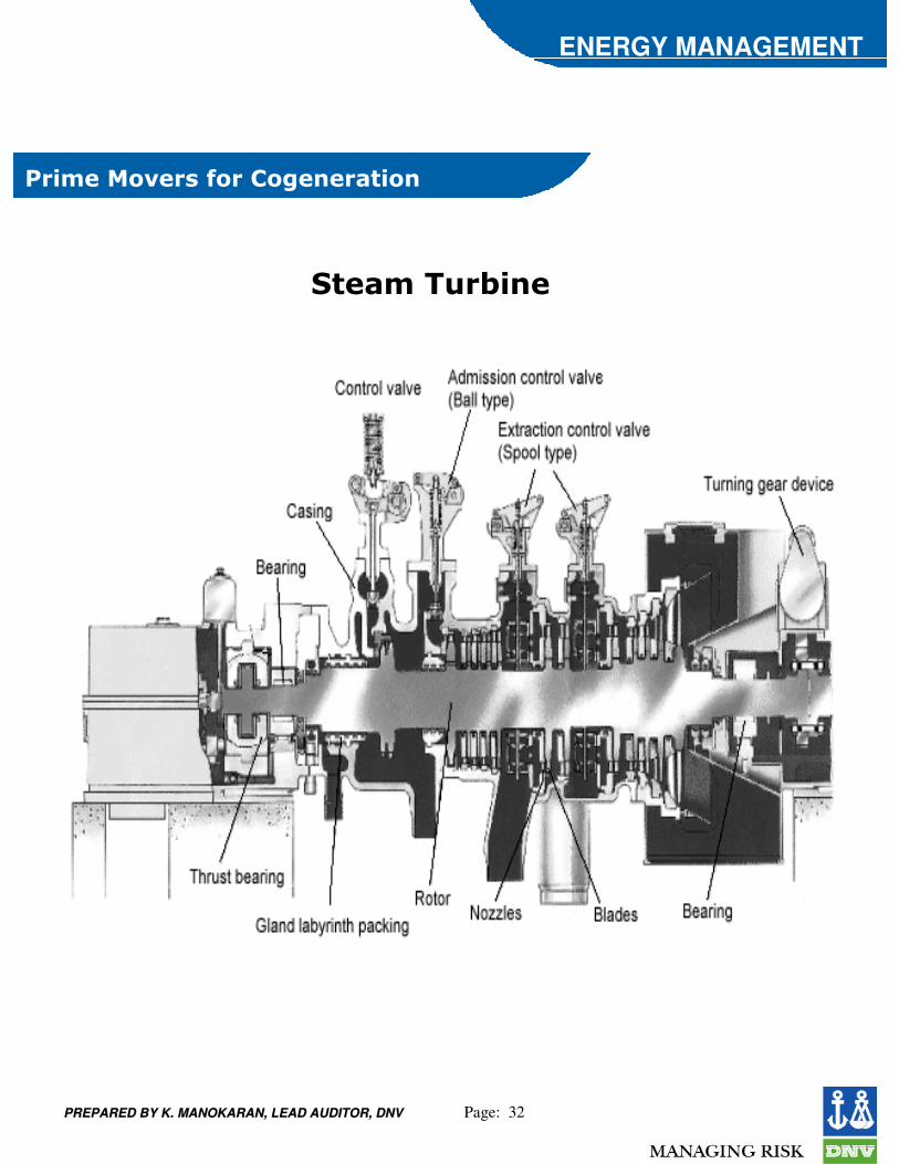
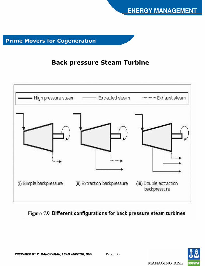
��!&��3�/��%������������� !��
� ��&��'�(!��
PREPARED BY K. MANOKARAN, LEAD AUDITOR, DNVPREPARED BY K. MANOKARAN, LEAD AUDITOR, DNV Page: 33
ENERGY MANAGEMENT
���0�"��%%'���� ��&��'�(!�����
��!&��3�/��%������������� !��
PREPARED BY K. MANOKARAN, LEAD AUDITOR, DNVPREPARED BY K. MANOKARAN, LEAD AUDITOR, DNV Page: 34
ENERGY MANAGEMENT
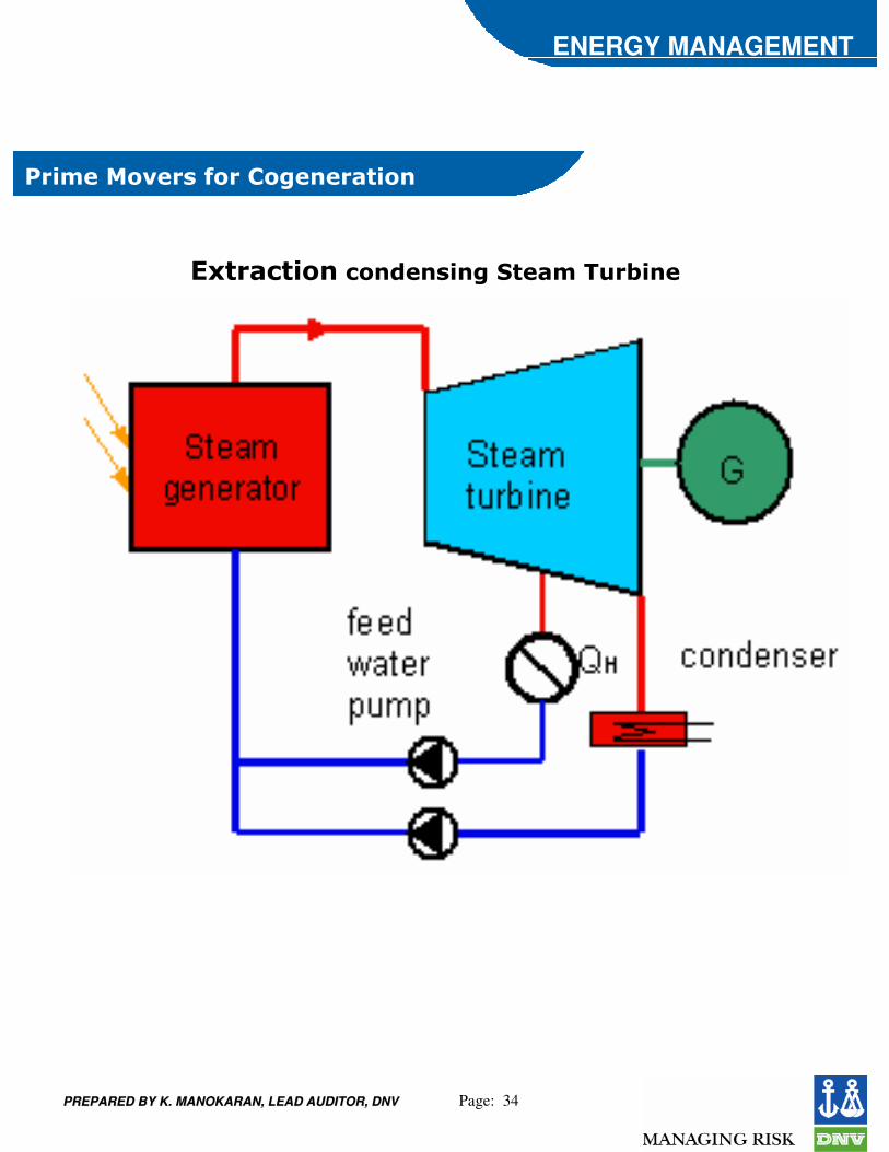
�4 ��� !��������%!���� ��&��'�(!��
��!&��3�/��%������������� !��

PREPARED BY K. MANOKARAN, LEAD AUDITOR, DNVPREPARED BY K. MANOKARAN, LEAD AUDITOR, DNV Page: 35
ENERGY MANAGEMENT
��%��'�(!��
��!&��3�/��%������������� !��
PREPARED BY K. MANOKARAN, LEAD AUDITOR, DNVPREPARED BY K. MANOKARAN, LEAD AUDITOR, DNV Page: 36
ENERGY MANAGEMENT
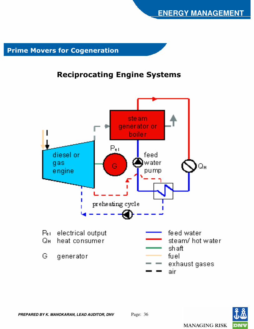
��!"���� !������!����)% �&%
��!&��3�/��%������������� !��
PREPARED BY K. MANOKARAN, LEAD AUDITOR, DNVPREPARED BY K. MANOKARAN, LEAD AUDITOR, DNV Page: 37
ENERGY MANAGEMENT
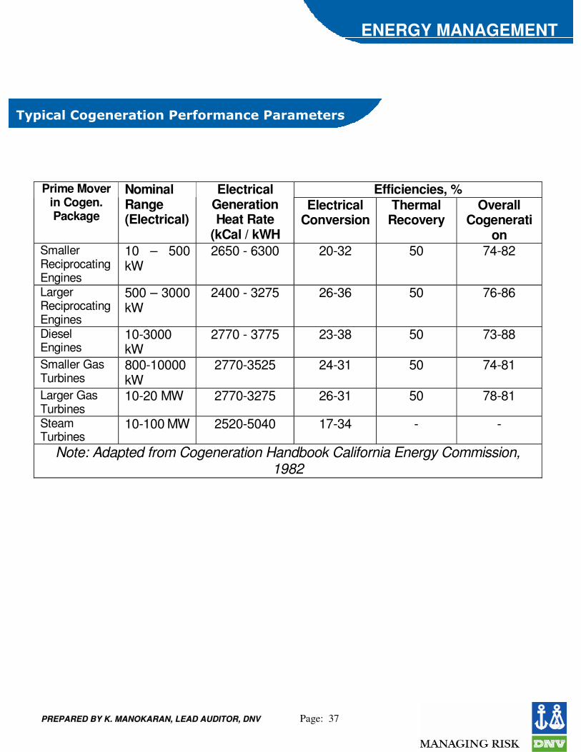
�)"!��#��������� !���������&���������&� ��%
Efficiencies, % Prime Mover in Cogen. Package
Nominal Range (Electrical)
Electrical Generation Heat Rate
(kCal / kWH
Electrical Conversion
Thermal Recovery
Overall Cogenerati
on Smaller Reciprocating Engines
10 – 500 kW
2650 - 6300 20-32 50 74-82
Larger Reciprocating Engines
500 – 3000 kW
2400 - 3275 26-36 50 76-86
Diesel Engines
10-3000 kW
2770 - 3775 23-38 50 73-88
Smaller Gas Turbines
800-10000 kW
2770-3525 24-31 50 74-81
Larger Gas Turbines
10-20 MW 2770-3275 26-31 50 78-81
Steam Turbines
10-100 MW 2520-5040 17-34 - -
Note: Adapted from Cogeneration Handbook California Energy Commission, 1982
PREPARED BY K. MANOKARAN, LEAD AUDITOR, DNVPREPARED BY K. MANOKARAN, LEAD AUDITOR, DNV Page: 38
ENERGY MANAGEMENT
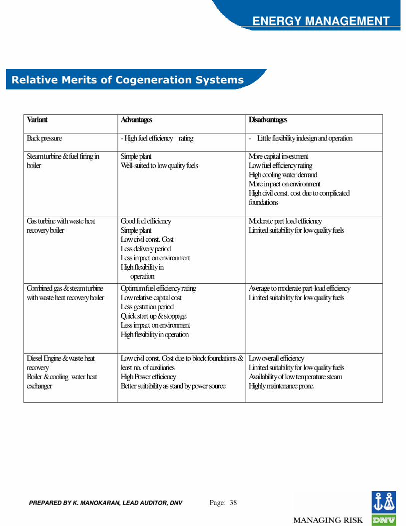
�#� !/��3��! %������������ !����)% �&%
Variant Advantages Disadvantages
Back pressure - High fuel efficiency rating - Little flexibility indesign and operation
Steam turbine & fuel firing in boiler
Simple plant Well-suited to low quality fuels
More capital investment Low fuel efficiency rating High cooling water demand More impact on environment High civil const. cost due to complicated foundations
Gas turbine with waste heat recovery boiler
Good fuel efficiency Simple plant Low civil const. Cost Less delivery period Less impact on environment High flexibility in operation
Moderate part load efficiency Limited suitability for low quality fuels
Combined gas & steam turbine with waste heat recovery boiler
Optimum fuel efficiency rating Low relative capital cost Less gestation period Quick start up & stoppage Less impact on environment High flexibility in operation
Average to moderate part-load efficiency Limited suitability for low quality fuels
Diesel Engine & waste heat recovery Boiler & cooling water heat exchanger
Low civil const. Cost due to block foundations & least no. of auxiliaries High Power efficiency Better suitability as stand by power source
Low overall efficiency Limited suitability for low quality fuels Availability of low temperature steam Highly maintenance prone.