Embed Size (px)
Citation preview

3-VALVE MANUAL CENTURION™
GAS SOURCE MANIFOLD
OPERATION & MAINTENANCE MANUAL
Part Number S052-0106 Rev. A
June, 2007
166 Keystone Drive
Montgomeryville, PA 18936 Telephone: 215-641-2700
Fax: 215-641-2714 National Service Center: 800-850-6231
Internet Address: http://www.matheson-trigas.com

ii
������������
© 2007 Matheson Tri-Gas All rights reserved. Printed in USA ���� ��������������
Auto-Purge is a registered trademark of Matheson TriGas. Auto-Guard, GEMS, and GEMS-Simon are trademarks of Matheson TriGas. Other product and company names mentioned in this manual may be the trademarks of their respective owners. ���� ���������� �
This document is concerned with the installation, operation, and maintenance of the 3-Valve Manually Operated Centurion Gas Source Manifold.
����� �� ������������
Document Part No. Edition Status Issued 3-Valve Manual Centurion Gas Source Manifold Operation & Maintenance Manual
S052-0106 Revision A Current June, 2007

iii
1. GENERAL DESCRIPTION OF CENTURION EQUIPMENT ..............................................1 1.1 Centurion Gas Source Manifold..........................................................................2
1.1.1 GSM Features.............................................................................................4 1.1.2 Gas Cylinder Enclosure Features ................................................................5
2. ENGINEERING DATA ......................................................................................................6
2.1 Gas Source Manifold..........................................................................................7 2.1.1 Utilities Required .........................................................................................7 2.1.2 Manifold Characteristics ..............................................................................7 2.1.3 Enclosure Characteristics............................................................................7
3. COMPONENT OPERATING CONVENTIONS ..................................................................9
3.1 Valves................................................................................................................9 3.2 Regulators..........................................................................................................9
4. SAFETY PRECAUTIONS ...............................................................................................10 5. PERSONNEL TRAINING................................................................................................12 6. INSTALLATION..............................................................................................................13
6.1 Equipment Unpacking and Insurance Claims....................................................13 6.2 Installation Personnel .......................................................................................13 6.3 General Installation Recommendations.............................................................13 6.4 GSM and CE Enclosure Installation..................................................................14 6.5 GSM Utilities ....................................................................................................15 6.6 GSM Process Gas Delivery Line and Vent Line ................................................16 6.7 GSM Accessory Monitors and Controls.............................................................17 6.8 GSMC installation.............................................................................................17 6.9 Post-Installation Tests ......................................................................................17 6.10 Initial System Start-Up....................................................................................18
7. OPERATION ..................................................................................................................19
7.1 3 Valve Manifold Cylinder Change Procedure...................................................20 7.2 3 Valve Manifold Maintenance Purge Procedure...............................................23 7.3 3 Valve Line Maintenance Purge Procedure .....................................................25 7.4 3 Valve Manifold Overnight Shutdown Purge Procedure ...................................27 7.5 Automatic Switchover Operation.......................................................................29
8. GSM MAINTENANCE.....................................................................................................30
8.1 Maintenance Personnel ....................................................................................30
9. TROUBLESHOOTING....................................................................................................30 9.1 Manifold Indication: High Delivery Pressure ......................................................30 9.2 Manifold Indication: High Manifold Pressure During Evacuation........................30 9.3 Manifold Indication: Low Manifold Pressure During Purge.................................30 9.4 Manifold Indication: Low Cylinder Pressure.......................................................31 9.5 Manifold Indication: Excess Flow Shutdown......................................................31 9.6 Manifold Indication: Low Cylinder Weight..........................................................31
10. SERVICE POLICY........................................................................................................31 11. GLOSSARY..................................................................................................................32

iv
LIST OF FIGURES Figure 1. 3-Valve Manual Centurion GSM Typical System Flow Schematic.........................2 Figure 2. 3-Valve Manual Centurion 2 Cylinder Panels and Dedicated Purge
Cylinder Typical System Flow Schematic.............................................................3
LIST OF TABLES Table 1. Cylinder Enclosure Specifications ........................................................................6 Table 2. ..........................................................................................................................16

1
1. General Description of Centurion Equipment The purpose of the 3-Valve Manual Centurion Gas Source Manifold (GSM) is to supply pressure-regulated non-hazardous process gas to either a gas distribution manifold or process equipment. The manifold is intended for high purity applications. While the 3-Valve Manual Centurion GSM is designed for use with non-hazardous gases, Auto-Purge® manifolds are specifically designed for hazardous gases and have better purge performance and are recommended for toxic, corrosive, and most reactive gas services to improve performance and safety. Many novel features of this equipment assure safety, dependability, ease of use, economy, and a minimal requirement for maintenance, while preserving gas purity. Many different features and options are offered to be able to provide a manifold that addresses each customer's requirements. In addition many customers have special requirements that result in designs specific for that customer. Therefore, the equipment discussed in this manual may not exactly represent the equipment purchased by each customer. All valves are manually operated on 3-Valve Manual Centurion GSMs except for automatic switchover valves,if they are included in these systems. This operation and maintenance manual concentrates on gas source manifold features—controller features, if any, are discussed in other operations manuals. 1.1. Centurion Gas Source Manifold The 3-Valve Manual (3VM) Centurion Gas Source Manifold (GSM) typically receives a pressure-unregulated process gas from a gas cylinder; the same pressure-regulated gas is then delivered to process equipment, either directly or indirectly via a Gas Distribution Manifold (GDM). 3-Valve manifolds are designed for use with non-hazardous gases. The standard valves supplied on 3-Valve manifolds are PGI, HPV, and HPI. A typical schematic for the 3VM Centurion GSM is shown in Figure 1. This manual describes purge procedures to enable cylinder changing and equipment maintenance to be accomplished without introducing contamination by atmospheric gases or particles. The 3VM Centurion GSM is typically wall mounted when used for non-hazardous gas applications. The Gas Source Manifold Controllers (GSMC), if included in this system, are located on a shelf above the GSM. There are many different configurations and combinations of GSMs, GSMCs, and that are currently available. A full loaded panel is shown in Figure 2.

2
Figure 1. 3-Valve Manual Centurion GSM Typical System Flow Schematic
LEGEND CFG Conical Filter Gasket, 0.4 Micron PLI Process Line Isolation Valve CAG Pressure Gauge REG Regulator HPI High Pressure Isolation Valve REL Relief Valve (Over-Pressure Relief) HPV High Pressure Vent Valve VGS Vacuum Generator Supply Valve PGI Purge Gas Inlet Isolation Valve VGI Vacuum Generator Isolation Valve PGO Purge Gas Orifice V V Vacuum Venturi Generator

3
Figure 2. 3-Valve Manual Centurion 2 Cylinder Panels and Dedicated Purge Cylinder Typical System Flow Schematic
LEGEND CFG Conical Filter Gasket, 0.4 Micron PGO Purge Gas Orifice CAG Pressure Gauge PLI Process Line Isolation Valve HPI High Pressure Isolation Valve REG Regulator HPV High Pressure Vent Valve REL Relief Valve (Over-Pressure Relief) IPS Indicating Pressure Switch VGI Vacuum Generator Isolation Valve LI Line Isolation Valve VGS Vacuum Generator Supply Valve LPI Low Pressure Isolation V V Vacuum Venturi Generator PGI Purge Gas Inlet Isolation Valve

4
1.1.1 GSM Features Standard GSM features include: • Application specific valve and regulator models designed to deliver the process gas at the required pressure
and flow rate • Springless diaphragm valves for most gases • Pressure transducers or pressure gauges for cylinder and delivery pressure indication • Ergonomic design provides convenient, safe cylinder connection at a height suitable for the typical worker • Improved purge efficiency by minimizing internal volume and internal surface area • Process gas excess flow switch(s) are supplied standard with HPM gases whose pressure at 70 °F is abov e
15 psig • Emergency shutoff valve is supplied standard on emergency protected manual manifolds for use with HPM
gases. • Venturi vacuum generator to evacuate the GSM to less than 150 Torr during the purge procedure evacuation
step • Pigtail inert gas bleed to virtually eliminate atmospheric contamination entering the pigtail during a cylinder
change procedure (an orifice is installed in the purge gas supply line to limit purge gas flow) Typical GSM options include: • Pressure display for process gas supply and delivery lines • Sample port to perform inboard helium leak testing of the manifold via the delivery line, sampling of the
manifold process gas, or argon purging of the delivery line during installation welding • All metal process line filter to remove all particles greater than 0.003 µm (a nickel media filter can also be
installed) • Purge gas bleed valve to provide an inert gas bleed as described above using a valve in place of the orifice
(the valve can be fully opened for more efficient purge gas delivery line purging) • A Nanochem® purifier to purify and filter the process gas prior to exiting the GSM (option is only available for
gases that can be purified using one of the Nanochem® resins) • Vacuum isolation valves to perform inboard leak testing of the cylinder connection via the vent header after
each cylinder change and to monitor for seat leakage from the HPV and LPV valves • Final process line isolation valve to enable replacement of GSM without compromising the integrity of the
process gas delivery line • High pressure purge supply to perform a pressure decay leak test on the pigtail after a cylinder change • Cylinder scale for monitoring residual content of a liquefied compressed gas 1.1.2 Gas Cylinder Enclosure and Wall Mount Panel F eatures

5
The gas cylinder enclosure also serves as the enclosure for the GSM. Single, dual, or triple cylinder models are produced to accommodate one, two, or three cylinders (typically 1 or 2 process gas cylinders with or without a purge gas cylinder); the gas cylinder enclosure is typically used for hazardous gases. The wall mount panel mounts two manifolds with an automatic switchover assembly to a single panel; the wall mount panel is typically used for non-hazardous gases or for hazardous gases located outdoors. Gas cylinder enclosure features include: • Underwriter's Laboratories approved fire sprinkler head • Large wire reinforced glass window that can be opened independently • Polycarbonate plastic safety shield protects users when window is open. Typical gas cylinder enclosure options include: • Hazardous gas detectors • Door lock • Gas cylinder temperature control equipment (45 to 100 °F; 7 to 38 °C) • Door or window open monitor • Exhaust pressure monitor • Infrared fire monitor Wall mount panel features include: Rigid support plate to secure manifold and components

6
2. ENGINEERING DATA 2.1 Gas Source Manifold 2.1.1 Utilities Required • Utilities requirements are determined by GSM Type (wall mount or cabinet mount) • Purge gas
Inert gas (typically nitrogen, argon, helium, or some mixture), filtered to 0.01 µm, 99.999 percent pure Pressure range: 85 to 95 psig
• Vacuum generator supply nitrogen Nitrogen filtered to 1.0 µm, 99 percent pure Pressure range: 70 to 110 psig Nitrogen usage: 60 slpm at 80 psig supply pressure Vacuum generated: 26” Hg (100 Torr)
• Vent from vacuum generator exhaust: suitable for intended process gas • Electric power (only required if a controller is used)
Line voltage: 110 to 240 VAC, An independent, external power disconnect (not provided) should be installed for each controller
• Facility exhaust for enclosure: suitable for intended process gas
Table 1. Cylinder Enclosure Specifications
(With Window
Open) (With Window
Closed)
Cabinet Model
Exhaust Duct Diameter
Size
Duct Flow
(scfm)
Duct Velocity (fpm)
Window Opening
(sq. inches)
Max Flow
(scfm)
Min Flow
(scfm)
Dimensions in inches (cm)
W x D x H
1CE 6" 350 1,780 72 150 50 15x23x87 (38x58x221cm)
2CE 6" 350 1,780 187 200 75 25x23x87 (64x58x221cm)
3CE 8" 550 1,575 259 320 100 40x23x87 (102x58x221cm)
1CE-200 8" 850 2,435 72 500 425 15x23x87 (38x58x221cm)
Maximum flow is with fully-open damper on door. Minimum flow is with closed damper. Exhaust sizing should be based on maximum flow.
Minimum static pressure requirement at enclosure exhaust connection is 0.4 in. H2O except for 1CE-200 which is at 1.00 in. H2O. Damper on 1CE-200 must be adjusted to meet the 200 fpm ventilation velocity as required by the Uniform Fire Code.
Height dimension includes controller.

7
• Pneumatic supply for valve operation (typically supplied via GSMC)
Nitrogen or clean dry air, filtered to 1.0 µm Pressure range: 70 to 110 psig
• Water supply for fire sprinkler Static (nonflowing) pressure: 175 psig maximum Dynamic (flowing) pressure: 7 psig minimum Water usage: 7 to 36 gpm depending upon supply pressure 2.1.2 Manifold Characteristics
• Operating pressures: Low pressure side: 125 psig maximum High pressure side: 3000 psig maximum depending on manifold components and process gas Purge gas: 125 psig maximum (if high pressure purge option is chosen, then pressure rating increases to 2500 psig maximum when high pressure components are used)
• Operating temperature: Manifold: 32°F to 120°F 2.1.3 Enclosure Characteristics The all welded gas cylinder enclosure is ruggedly constructed of 11 gage (0.1196 inch) cold-rolled steel with a light gray, corrosion-resistant, polyurethane matte finish on all surfaces; dimensions are shown in Table 1. The enclosure is NEMA 1 rated for indoor use only. The interior is designated a Class I Division 2 location when used with flammable or pyrophoric gases. The electrical equipment inside the enclosure is acceptable for that location (customer specified or installed equipment may not be acceptable - it is the users responsibility to use acceptable equipment). The wall mount panel is constructed of 13 gage stainless steel with mirror finish.; dimensions are shown in Table 1. When properly installed all Centurion GSMs and gas cylinder enclosures have been designed to meet Uniform Building Code™ (UBC) and Uniform Fire Code (UFC) safety regulations. Because regulations are subject to interpretation, which can vary from location to location, it is recommended that the user consult the local authority for their specific installation. New changes to the Uniform Fire Code mandated a special cylinder gas cabinet for Silane (SiH4). This special enclosure is for single gas cylinders only. The enclosure has adjustable air intake louvers in the door and rear wall. The Silane cylinder enclosure must be positioned to allow for air flow into the intake in the enclosure rear; the enclosure rear or side should be located 1 inch minimum from a wall. The Silane single cylinder enclosure is designed to provide for a minimum 200 ft3/min air velocity across unwelded process gas connections inside the enclosure. All gas cylinder enclosure doors and windows are gasketed and are provided with spring closers and flush mounted, spring loaded latches. Adjustable air intake louvers at the bottom of the door enable accurate adjustment of exhaust air flow through enclosure. A heavy-duty rubberized floor covering inside the gas cylinder enclosure protects the enclosure floor from cylinder impact and sliding. A permanently installed ¼ - inch (6.3 mm) thick, high impact-strength polycarbonate plastic safety shield installed immediately inside the enclosure window protects users from gas exposure and other hazards while observing operation, adjusting pressure regulators, or changing cylinders. With the safety shield in place, adequate gas cylinder enclosure exhaust flow is maintained, even when the gas cylinder enclosure window is open.

8
Gas cylinder enclosure roof penetrations accommodate process gas delivery, purge gas inlet, vacuum generator supply, and vent exhaust lines. A 6-inch (152 mm) diameter collar welded to the roof of the single and dual gas cylinder enclosure enables connection to a facility exhaust duct. The diameter of the triple gas cylinder enclosure and Silane single cylinder enclosure exhaust duct is 8-inches (203 mm).

9
3.0 COMPONENT OPERATING CONVENTIONS 3.1 Valves • Manual valves are closed when the operator is positioned fully clockwise (CW). • Manual valves are open when the operator is positioned fully counterclockwise (CCW). • Pneumatic valves are closed when there is no pressure supply to the actuator. Pneumatic valves are open
when 70 to 110 psig is supplied to the actuator. The pressure supply is controlled by the GSMC. 3.2 Regulators
WARNING! When pressure exists on the low pressure side of a tied-diaphragm pressure regulator, rotating the adjustment knob counterclockwise (i.e. closing or decreasing the regulator) may cause damage. The system pressure should be vented if possible before turning the adjustment knob counterclockwise.
• Delivery pressure is minimal when the adjustment knob is positioned fully counterclockwise (CCW). • Delivery pressure increases as the adjustment knob is rotated clockwise (CW).

10
4. SAFETY PRECAUTIONS
DANGER!
FOLLOW ALL SAFETY PRECAUTIONS TO THE LETTER Under no circumstances should you attempt to circumvent compressed gas equipment safety precautions. Compressed gases and associated equipment are potentially dangerous; persons that have not been formally trained must not use them. Only by strictly adhering to all safety precautions can the risk of personal injury or damage to equipment be avoided.
DANGER! Matheson TriGas recommends that whenever possible, the flow of process gas inside the enclosure should be shut off and all lines purged when maintenance is performed. If this is not possible, then the user should consult their Safety and Industrial Hygiene department to determine the appropriate personnel protective equipment that must be worn during maintenance.
This manual cannot replace formal training in compressed gas equipment safety principles. This section is intended only as a reminder to adequately trained personnel that already understand and follow accepted safety practices. • Installation, operation, and maintenance of gas control equipment should be performed by trained personnel
only. • Follow all installation, operation, and maintenance instructions to the letter. Always replace all components,
fasteners, labels, and other items exactly as originally installed; do not modify anything without authorization. • Failure to follow recommended procedures may result in personal injury and equipment failure or
contamination. • Equipment not in adequate operating condition should be shut down immediately. Do not attempt to use
equipment that is not operating properly. • Never attempt to defeat interlocks or other safety devices. • Operation of valves in the manual mode may override GSMC safety interlocks that would normally protect
equipment and personnel during automatic valve operation. Be especially attentive when valves are operated in the manual mode.
• Because 110 or 220 VAC electrical power is applied to the equipment, a shock hazard exists if the GSMC
enclosure is entered during operation. Disconnect electrical power prior to disassembly or replacement of electrical components within the GSMC, and prior to connecting or disconnecting wiring, including sensor output leads, within the GSMC.

11
• Material Safety Data Sheets for all gases used in the facility should be available for consultation by all
concerned personnel. These data are obtainable from the gas supplier. • Make sure the gas cylinder enclosure exhaust is functioning properly before starting a maintenance
procedure. Accidental process gas release is more likely to occur during maintenance than during day - to - day operation.
• To avoid injury and discourage tampering, the gas cylinder enclosure door and window should remain closed
and secured during normal operation. The door should be opened only when changing process gas cylinders or performing system maintenance. The window should be opened only when visually checking GSM operation or making adjustments. If the exhaust equipment is not functioning, do not open the gas cylinder enclosure door or window.
• Close the process gas source valve before starting a maintenance procedure. If this practice is followed,
accidental gas release will involve only a small volume of gas. While this practice is required only for GSM maintenance, its general adoption is worth consideration.
• Equipment used in or exposed to hazardous gas service must be purged with an inert gas prior to
disassembly. • Even though equipment may have been properly purged, trace amounts of gases may remain. For this
reason, components and piping that have been exposed to hazardous gases should be carefully labeled with the names of the gases and stored or discarded in accordance with safety ordinances and regulations.
• Personnel working with hazardous gases or contaminated components must be provided with suitable
personnel protective equipment. • Vent all equipment prior to disassembly. Unexpected jet noise accompanying release of a high-pressure gas
can frighten workers and precipitate an accident. • Should fire, release of toxic or otherwise hazardous gases, or another potentially dangerous situation arise,
press the GSMC SHUTDOWN button, then clear the location. • Installation of gas cylinder enclosures and replacement of gas cylinders may require strenuous lifting or
manipulation; if accomplished in an unsafe manner, injury or equipment damage could result. It is the responsibility of the user to employ safe cylinder lifting and manipulation techniques as described in NIOSH Publication 81-122.
• Mechanical or electrical maintenance should follow lockout/tagout procedures described in OSHA document
29 CFR 1910.147 Control of Hazardous Energy (Lockout/Tagout) and 29 CFR 1910.331-335 Electrical Safety-Related Work Practices (7-1-94 Edition).

12
5. PERSONNEL TRAINING The Centurion GSM flow path and operation is logical and straightforward, making extensive additional training unnecessary. Personnel should review this manual thoroughly before attempting to install or operate the equipment. Installation and maintenance should be executed only by personnel trained and experienced in general electromechanical assembly and repair and who thoroughly understand gas control equipment. Administrative and supervisory personnel are encouraged to achieve a thorough understanding of the operation of all pertinent MTG gas control equipment. MTG Field Service personnel can provide authoritative operation and maintenance training.

13
6. INSTALLATION Figures pertaining to equipment installation are collected at the end of the section. 6.1 Equipment Unpacking and Insurance Claims If installation has been contracted with MTG, please do not unpack any equipment, as MTG Field Service prefer to open the boxes themselves. Exteriors of all packages nevertheless should be carefully inspected on arrival as described below. Because all shipments are FOB the MTG factory, the title to purchased goods passes to the customer upon pickup by the carrier. Damage sustained during transit accordingly is the responsibility of the carrier, with whom insurance claims for damage should be filed. Please inspect all shipping cartons immediately upon receipt. Should damage or stains be observed, immediately notify the carrier requesting that an insurance claims agent be present when the carton is opened. Should any damage be discovered, retain the carton, contents, and all packing materials for inspection by the insurance claims agent. 6.2 Installation Personnel Equipment should be operated only by trained personnel. Installation of equipment should be entrusted only to personnel that are in addition trained and experienced in electromechanical assembly techniques. Persons that do not understand the principles of gas equipment operation can injure themselves and co-workers. They can also damage equipment, resulting in unexpected downtime and expense. Before starting a job, all personnel responsible for equipment installation or operation must fully understand the specific procedures to be accomplished and all pertinent safety considerations. Because optional or non-standard components often are included in equipment configuration, installation details may differ substantially from the generic instructions provided. If facility personnel are not confident in their abilities to install or operate the equipment, MTG Field Service should be contacted for assistance. MTG specialists are available to assist equipment owners and provide authoritative training on all aspects of equipment installation, operation, and maintenance. 6.3 General Installation Recommendations All installation personnel should be familiar with these recommendations that are pertinent to several sections of this manual. • The gas cylinder enclosure safety shield is constructed of polycarbonate plastic. Although this material is of
exceptional impact strength, it also is easily scratched and readily damaged by contact with many organic solvents and vapors, including practically all alcohols, esters, and ketones. Soap and water are acceptable cleaning agents. Never attempt to clean the plastic safety shield with an incompatible solvent that would compromise its strength or transparency.
• Inspect face - seal connector gasket sealing surfaces for dirt, scratches, dents, pitting, or corrosion. Clean or
replace affected parts before assembly. • Tighten face - seal connections exactly 1/8 turn beyond finger tight. Overtightening can damage the
connection; undertightening can cause leakage. • Always install new gaskets when assembling face - seal connections.

14
• When working with components that contact process or purge gases - for example, face - seal connection gaskets - always wear new latex gloves to avoid fingerprint contamination.
• Pneumatic supply tubing is best cut with a plastic tubing cutter rather than scissors or diagonal pliers. Plastic
tubing cutters are available from tool distributors. • Following installation, leak test all affected process gas connections. Leak testing procedures are
documented in SEMI F11, ASTM E 498, and ASTM E 4992. Three possible leak test methods are described below.
— For inboard testing with a helium-mass spectrometer leak detector, leakage at any connection should not
exceed 1 x 10⁻⁹ sccs. The inboard leak test evacuates the GSM with the leak detector and sprays helium at the affected locations.
— For outboard pressure decay testing, the pressure decay after four hours should not exceed 1 percent of
the initial value after compensation for any temperature changes. The pressure decay test pressurizes the high pressure side of the GSM to design pressure and then monitors the supply pressure sensor.
— For outboard leak testing using a sniffer probe, leakage from any connection should not cause an
increase in helium concentration greater than 1 ppm above background. The outboard leak test pressurizes the affected regions of the GSM with 100 percent helium to 100 percent of the system design pressure.
CAUTION! When performing inboard leak testing using a helium mass spectrometer leak detector, isolate the gas source manifold prior to venting the leak detector. Many leak detectors backfill the evacuated line with atmosphere and this can contaminate the gas source manifold.
1. SEMI Standards Order Department, 805 East Middlefield Road, Mountain View CA 94043-4080 2. ASTM, 1916 Race Street, Philadelphia PA 19103 6.4 GSM and CE Enclosure Installation GSM facility connection locations are shown in Figures 3 through 8.
WARNING!
IMPROPER LIFTING OF HEAVY EQUIPMENT CAN CAUSE INJUR Y Because the GSM and CE are heavy, only workers trained in NIOSH - approved lifting techniques should be assigned to either installation or removal efforts. In this way personal injury and damage to equipment can effectively be avoided.

15
1. For cylinder enclosures: Level and anchor the GSM enclosure assembly to an architecturally stable element using four 3/8 - inch anchor bolts with washers through the four holes in the floor of the enclosure or on the wall mount panel in accordance with Uniform Building Code™ requirements.
For wall mount systems: Attach the GSM wall mount panel to an architecturally stable element using four 3/8 - inch screws through the holes on the panel in accordance with Uniform Building Code™ requirements. Attach Cyl-Safe™ cylinder restraints to an architecturally stable element using four 3/8 - inch screws per restraint in accordance with Uniform Building Code™ requirements. The Uniform Building Code™ has different requirements depending upon the location of the installation; for instance, earthquake zone 4 location have more stringent structural tie down requirements. Locations of CE gas cabinet anchor points are shown in the figures at the end of this section. The equipment is not intended for exterior installation. Equipment that is required to be installed outside a building should be protected from harsh environments through use of overhead covers, partial walls, environmental conditioning equipment, etc.
6.5 GSM Utilities
WARNING!
PROPER EXHAUSTING OF THE PROCESS GAS IS REQUIRED Exhaust requirements differ according to the intended process gas. Inert and non-toxic gases, for example, are typically exhausted to a burner. When in doubt as to the exhaust disposition of a specific gas, consult appropriate authorities. Equipment installation, including duct material selection, should be managed by qualified personnel that understand the hazard potential of the intended process gas.
1. Using materials compatible with the intended process gas, connect the 6-inch (single or dual gas cylinder
enclosure) or 8-inch (triple GSM enclosure, single enclosure for Silane and Silane mixtures) exhaust outlet collar atop the gas cylinder enclosure to a suitable facility exhaust line.
Depending upon the process gas, effluent treatment may be required. SEMI F5 Guide for Gaseous Effluent Handling can provide information on a recommended type of treatment system.
2. Install an air flow damper in the connecting exhaust duct.
With the GSM enclosure door closed and window open, adjust the exhaust duct damper to achieve an exhaust duct air flow within the values shown the "window open" column of Table 2. This will ensure that an air velocity of at least 200 ft3/min average exists within the plane of the plastic safety shield opening.
3. With the GSM enclosure door closed and window open, verify that an exhaust air velocity of 150 ft3/min
minimum exists at all points within the plastic safety shield opening. Measurements must be made within the plane of the plastic.
4. Adjust the GSM enclosure door louver damper(s) so that, with the GSM enclosure door and window
closed, the exhaust duct air flow is within the values shown in the "window closed" column of Table 2.

16
This will maintain a constant air flow through the enclosure to "purge" the interior in case of process gas piping leakage.
Table 2. Enclosure Air Flow Requirements
Enclosure Model
Window Open (scfm)
Window Closed (scfm)
1CE (Single)
100-115
50-150 2CE (Dual)
260-280
75-200
3CE (Triple)
360-390
100-320 1CE (Silane)
150 minimum
425-500
SGS cabinets are designed for connection to a facility exhaust system capable of achieving a minimum static pressure of 0.75" of H2O in the exhaust duct measured one foot downstream of the gas cabinet exhaust outlet collar. 5. Connect a source of 10.0 µm filtered regulated nitrogen at 70-110 psig (483-758 kPa) pressure and 60
slpm to the vacuum generator supply tube stub connection. To facilitate vacuum generator maintenance, installation of a manual shutoff valve on the vacuum generator supply line just outside the gas cylinder enclosure using compression fittings is recommended.
6. Connect a source of 0.01 µm filtered regulated purge gas at 85-95 psig (586-655 kPa) pressure and 10
slpm to the ¼ - inch purge gas supply face seal connection on the GSM inside the gas cylinder enclosure. For GSMs installed in cylinder enclosures, route this line via its penetration in the roof of the gas cylinder enclosure. For GSMs installed on wall mount panels, route this line as desired. To facilitate mainte-nance, install a manual shutoff valve on the purge gas supply line leading to each gas cylinder enclosure.
7. Connect a source of 1.0 µm filtered regulated nitrogen or clean dry air at 70-110 psig pressure to the
GSMC for valve actuation. 8. Connect a fire protection water source at 175 psig maximum to the sprinkler inlet ½ - inch male NPT
connection on the top of the cylinder enclosure. 6.6 GSM Process Gas Delivery Line and Vent Line 1. Connect a ¼ - inch 316L SS process gas delivery line between the GSM outlet face seal connection and
the process gas inlet(s) at the GDM or process equipment. For GSMs installed in cylinder enclosures, route this line via its penetration in the roof of the gas cylinder enclosure. For GSMs installed on wall mount panels, route this line as desired.
All connections outside the enclosure on all HPM process gas lines must be welded and braced in accordance with safety ordinances and regulations. Only welded connections must be installed on HPM process gas lines external to the gas cylinder enclosure.
Safety ordinances may require dual containment (coaxial) delivery lines for certain gases and locations. Depending upon the process gas, the use of materials other than 316L SS may be necessary for the process gas delivery line. For example, Hastelloy® C-22 lines may be desired for their superior corrosion resistance to gases such as hydrogen chloride (HCl) and chlorine (Cl2). Depending upon the flow rate, the use of larger diameter process gas delivery lines may be necessary to reduce the pressure drop between the GSM and the GDM or process tool.

17
2. If a GSM is intended for use with a hazardous process gas, consult the gas supplier for recommendations
concerning GSM vent line routes and outlet locations to preclude reflux of specific hazardous gases into the gas cylinder enclosure. Then similarly connect a 3/8 - inch 316L SS vent line between the GSM process gas vent exhaust tube stub and a suitable facility exhaust duct.
Manifold vent lines terminating within an exhaust duct should be positioned horizontally near the center line of the duct, point downstream, and terminate downstream of the gas cylinder enclosure (see Figure 8 for a typical installation).
Depending upon the process gas, effluent treatment may be required. SEMI F5 Guide for Gaseous Effluent Handling can provide information on a recommended type of treatment system.
3. Label the equipment per federal and state OSHA standards. Specifically, tag all GSM process gas, purge
gas, and vacuum generator supply lines with name and flow direction in accordance with NFPA regulations. Diagram the intended process gas and flow direction on the gas cylinder enclosure door.
6.7 GSM Accessory Monitors and Controls 1. Install an exhaust differential pressure switch (e.g., Magnehelic or Photohelic) on the gas cylinder
enclosure exhaust ducting. This device is recommended by SEMI S2 Safety Guidelines for Semiconductor Manufacturing Equipment for HPM gas applications. Direct the switch output to either a facility exhaust system monitor or GSMC digital input channel.
2. Install hazardous gas detection equipment as mandated by pertinent safety ordinances and regulations.
The output from this equipment should be directed to a GSMC digital input channel or to an appropriate accessory monitor.
3. Install a fire sensor within the gas cylinder enclosure for flammable and pyrophoric gases. This device is recommended by SEMI S2 Safety Guidelines for Semiconductor Manufacturing Equipment. The output from this equipment should be directed to a GSMC digital input channel or to an appropriate accessory monitor.
6.8 GSMC Installation A GSMC is required for 5-Valve Manual Centurion Gas Source Manifolds that have an ESO valve or an automatic switchover. Several controllers are currently available to perform these functions. Consult the GSMC operations manual for the specific controller chosen for installation procedures. 6.9 Post-Installation Tests
WARNING!
OPERATION OF UNTESTED EQUIPMENT CAN CAUSE INJURY All tests in this section must be completed to assure the equipment has been correctly installed and is safe to use. In addition, all tests specified in the GSMC operations manual must be completed prior to equipment operation.
1. Calibrate and test all of the pressure transducers for each manifold.

18
2. Perform a leak test of all process gas piping and components. 3. Confirm operation of the emergency shutdown button on GSMC for hazardous gases. 4. Confirm operation of all safety sensors such as fire sensor, cylinder exhaust pressure sensor, etc. 5. Confirm operation of excess flow switch shutdown circuit if so equipped. 6.10 Initial System Start-Up Prior to introducing process gas into the Centurion GSM, the user should perform a purge from the GSM through the distribution manifold (if applicable) to the process equipment. This process is not detailed in the operations manual because it requires knowledge of the configuration of the distribution manifold and process equipment. MTG recommends the general steps identified below modified as necessary based upon the user's equipment. • Secure process gas cylinder(s) and perform a cylinder valve shutoff leak test. • Perform a leak test of the entire process gas system. • Perform a flow-through purge from the GSM through the distribution manifold to the process equipment. • Perform a cycle purge from the GSM to the GDM or process equipment by alternating pressurization and
evacuation steps. • Additionally, perform a flow-through purge and cycle purge from the GDM to the process equipment if
applicable. • Sample the process line at the distribution manifold and process equipment. Verify that particulate levels and
chemical contamination levels are below required levels.

19
7. OPERATION Four purge procedures are described in this operations manual. Each purge operation is comprised of many steps, including many evacuation / pressurization cycles. The purge procedures described in the operations manual are: • Cylinder Change Purge: purges GSM from process gas cylinder valve outlet to HPI (ESO) - its purpose is to
be able to remove and replace gas cylinders • Manifold Maintenance Purge: purges GSM from process gas cylinder valve outlet to process line isolation
valve downstream of regulator (LPI or AS) - its purpose is to be able to remove and replace manifold components
• Line Maintenance Purge: purges GSM from process gas cylinder valve outlet to GDM or process equipment -
its purpose is to be able to perform maintenance on the process gas delivery line • Overnight Shutdown Purge: purges GSM from process gas cylinder valve outlet to process equipment;
process gas delivery line remains pressurized with purge gas to preclude contamination by effusion of atmospheric gases into manifold space - its purpose is to remove hazardous gases from the system in order to increase safety during facility downtimes.
The procedures described in this manual for the line maintenance and overnight shutdown purges use the HPV valve to evacuate the line. The purges would be more efficient if a vent valve located at the end of the process gas delivery line is used to evacuate the manifold. In addition, a flow-through purge from the GSM to the GDM or process equipment would also be more effective than the procedure described in this manual. A flow-through purge is recommended to be performed for hazardous gas applications.
WARNING!
IMPROPER LIFTING OF HEAVY EQUIPMENT CAN CAUSE INJUR Y Because compressed gas cylinders are heavy, only workers trained in NIOSH-approved lifting techniques should be assigned to either installation or removal efforts. This way, personal injury and damage to equipment can be avoided.
Before changing cylinders, we suggest reviewing § 4 (Safety Precautions), § 8.2 (General Maintenance Recommendations), and the appropriate operations manual for the GSMC. Never drop, strike, or improperly transport cylinders. Never use a pipe wrench on the compressed gas cylinder connection - always use an open-end or flare-nut wrench. Always install the cylinder valve cover before moving the gas cylinder. Always install a new cylinder connection gasket, if one is required.

20
7.1 5 Valve Manifold Cylinder Change Procedure 1. Close the cylinder valve (CV). 2. Close process isolation valve downstream of regulator (PLI or AS). 3. Open VGI valve. 4. Open VGS valve. 5. Open HPV valve and wait 15 seconds. Verify cylinder pressure indication is zero (0) psig. 6. Open the regulator (CW) 1 turn wait 15 seconds. Verify delivery pressure indication is zero (0) psig. 7. Close HPV valve. 8. Close regulator by turning regulator counter clock-wise (CCW). 9. Close HPI (ESO) and LPI valves. 10. Wait 3 minutes minimum, then again verify cylinder pressure indication is zero (0) psig or less. If pressure has
increased, then cylinder valve is leaking past the seat. If cylinder valve is leaking, open the valve and close again tightly; then return to step 6. Do not proceed if cylinder valve continues to leak; contact gas supplier for assistance.
11. Open HPV valve for 15 seconds. 12. Close HPV valve. Verify cylinder pressure indication is less than zero psig. 13. Open PGI valve for 6 seconds. 14. Close PGI valve. Verify cylinder pressure indication is approximately equal to purge gas inlet pressure (±10
psig). 15. Repeat steps 11 thru 14 ten (10) times. For hazardous process gases, repeat steps 11 thru 14 sixty (60)
times. 16. Close VGS valve. 17. Open PGI valve.
WARNING!
PIGTAIL BLEED FEATURE PRESSURIZES MANIFOLD Because the manifold has a purge gas bleed feature, the process gas cylinder connection line is pressurized with purge gas. Once the connection is loosed, the purge gas will vent and a low flow of purge gas will continue to flow out of the manifold side of the connection.
18. Separate the process gas cylinder connection from the pigtail connection. Discard the gasket, if applicable. 19. Install the cylinder cap protective cover; remove the cylinder and place the cylinder on a gas cylinder cart or in

21
a designated storage facility; install the safety chain to prevent accidental damage by falling. 20. Inspect the cylinder connection sealing surface on the pigtail for dirt, scratches, dents, pits, or corrosion.
Clean or replace parts as indicated. 21. Install the new cylinder and fasten the safety chain. Remove the protective heavy metal cap from the cylinder
valve. 22. Inspect the cylinder valve connection sealing surface for dirt, scratches, dents, pits, or corrosion. Clean as
indicated. Do not attempt to connect a cylinder that is in any way defective. 23. Wearing new latex gloves to avoid fingerprints, install a new cylinder connection gasket, if required, between
the connectors, and loosely make up the connection. 24. Wait 30 seconds to allow the pigtail bleed to purge through the pigtail and out the loose connection, then
finger tighten the connection. 25. With a suitable wrench, tighten the cylinder connection. (Always use a DISS Torque wrench for DISS
connections. Always use a backup wrench on CGA connections) 26. Carefully inspect all work. 27. Close PGI valve. 28. Open HPV valve for 15 seconds. 29. Close HPV valve. Verify cylinder pressure display indication is zero (0) psig. 30. Open PGI valve for 5 seconds. 31. Close PGI valve. Verify cylinder pressure display indication is approximately 90 psig. 32. Wait for 2 minutes minimum and monitor cylinder pressure display. A drop in pressure indicates a potential
leak most probably at the cylinder connection. If leakage is discovered, repair leaks and return to step 22. 33. Open VGS valve. 34. Open HPV valve for 15 seconds. 35. Close HPV valve. Verify cylinder pressure display indication is zero (0) psig or less. 36. Open PGI valve for 5 seconds. 37. Close PGI valve. Verify cylinder pressure display indication is approximately 90 psig. 38. Repeat steps 34 thru 37 ten (10) times. For hazardous process gases, repeat steps 34 thru 37 sixty 60 times. 39. Open HPV valve for 15 seconds. 40. Close HPV valve. Verify cylinder pressure display indication is zero (0) psig or less. 41. Close VGI valve. 42. Close VGS valve. 43. Open cylinder valve. Wait 5 seconds minimum or until cylinder pressure indication stabilizes. Verify full

22
cylinder pressure indication. 44. Close cylinder valve. 45. Wait for 2 minutes minimum and monitor cylinder pressure display. A drop in pressure indicates a potential
leak most probably at the cylinder connection. If leakage is discovered, close cylinder valve and repeat this entire procedure except repair leaks instead of replacing cylinders.
46. If the process gas uses a scale to determine when the cylinder contents' are nearly depleted, then adjust the
cylinder scale indication as required by the equipment. Refer to the applicable controller operations manual for instructions.
47. Open cylinder valve. 48. Open HPI (ESO) valve. 49. Adjust regulator (CW) to desired delivery pressure. 50. Open LPI valve. 51. Open process isolation valve downstream of regulator (PLI ). 52. Manifold is now in SERVICE mode and supplying process gas.

23
7.2 5 Valve Manifold Maintenance Purge Procedure 1. Close the cylinder valve. 2. Close process isolation valve downstream of regulator (PLI ). 3. Open VGI valve. 4. Open VGS valve. 5. Open HPV valve and wait 15 seconds. Verify cylinder pressure indication is at least zero (0) psig. 6. Open the regulator fully by turning the handle (CW) wait 15 seconds. Verify delivery pressure indication is at
least zero (0) psig. 7. Close HPV valve. 8. Close LPI valve. 9. Wait 3 minutes minimum, then again verify cylinder pressure indication is zero (0) psig or less. If pressure has
increased, then cylinder valve is leaking past the seat. If cylinder valve is leaking, open the valve and close again tightly; then repeat step 3 thru 9. Do not proceed if cylinder valve, continues to leak; contact gas supplier for assistance.
10. Open HPV valve for 30 seconds 11. Close HPV valve. Verify cylinder pressure indication is zero (0) psig or less. 12. Open PGI valve for 10 seconds. 13. Close PGI valve. Verify cylinder and delivery pressure indication is approximately equal to purge gas inlet
pressure (± 10 psig). 14. Repeat steps 10 thru 13, ten (10) times. For hazardous process gases, repeat steps 10 thru 13 sixty (60)
times. 15. Close VGS valve. 16. Open HPV valve for 10 seconds. 17. Close HPV valve. Verify cylinder pressure indication is zero (0) psig. 18. Perform manifold maintenance. 19. Open PGI valve for 10 seconds. 20. Close PGI valve. Verify cylinder and delivery pressure indication is approximately equal to purge gas inlet
pressure (± 10 psig). 21. Wait for 2 minutes minimum and monitor cylinder pressure and delivery pressure displays. A drop in pressure
indicates a potential leak. If leakage is discovered, repair leaks and return to step 18. 22. Open VGS valve. 23. Open HPV valve for 30 seconds.

24
24. Close HPV valve. Verify cylinder pressure display indication is zero (0) psig or less. 25. Open PGI valve for 10 seconds. 26. Close PGI valve. Verify cylinder and delivery pressure indication is approximately equal to purge gas inlet
pressure (± 10 psig). 27. Repeat steps 23 thru 26, ten (10) times. For hazardous process gases, repeat steps 23 thru 26 sixty (60)
times. 28. Open HPV valve for 30 seconds. 29. Close HPV valve. Verify cylinder pressure indication is zero (0) psig or less. 30. Close VGI valve 31. Close VGS valve. 32. Fully decrease regulator (CCW). 33. Close HPI (ESO) valve. 34. Open the cylinder valve. Wait 5 seconds minimum or until cylinder pressure indication stabilizes. Verify full
cylinder pressure indication. 35. Close cylinder valve. 36. Wait for 2 minutes minimum and monitor cylinder pressure display. A drop in pressure indicates a potential
leak. If leakage is discovered, close cylinder valve and return to step 3. 37. Open HPI (ESO) valve. 38. Open cylinder valve. 39. Increase regulator (CW) to desired delivery pressure. 40. Open LPI valve. 41. Open process isolation valve downstream of regulator (PLI). 42. Manifold is now in SERVICE mode and supplying process gas.
25
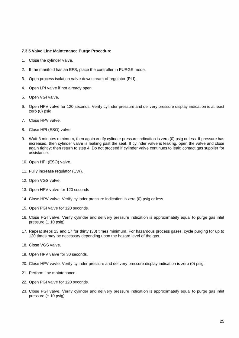
7.3 5 Valve Line Maintenance Purge Procedure 1. Close the cylinder valve. 2. If the manifold has an EFS, place the controller in PURGE mode. 3. Open process isolation valve downstream of regulator (PLI). 4. Open LPI valve if not already open. 5. Open VGI valve. 6. Open HPV valve for 120 seconds. Verify cylinder pressure and delivery pressure display indication is at least
zero (0) psig. 7. Close HPV valve. 8. Close HPI (ESO) valve. 9. Wait 3 minutes minimum, then again verify cylinder pressure indication is zero (0) psig or less. If pressure has
increased, then cylinder valve is leaking past the seat. If cylinder valve is leaking, open the valve and close again tightly; then return to step 4. Do not proceed if cylinder valve continues to leak; contact gas supplier for assistance.
10. Open HPI (ESO) valve. 11. Fully increase regulator (CW). 12. Open VGS valve. 13. Open HPV valve for 120 seconds 14. Close HPV valve. Verify cylinder pressure indication is zero (0) psig or less. 15. Open PGI valve for 120 seconds. 16. Close PGI valve. Verify cylinder and delivery pressure indication is approximately equal to purge gas inlet
pressure (± 10 psig). 17. Repeat steps 13 and 17 for thirty (30) times minimum. For hazardous process gases, cycle purging for up to
120 times may be necessary depending upon the hazard level of the gas. 18. Close VGS valve. 19. Open HPV valve for 30 seconds. 20. Close HPV vavle. Verify cylinder pressure and delivery pressure display indication is zero (0) psig. 21. Perform line maintenance. 22. Open PGI valve for 120 seconds. 23. Close PGI valve. Verify cylinder and delivery pressure indication is approximately equal to purge gas inlet
pressure (± 10 psig).
26
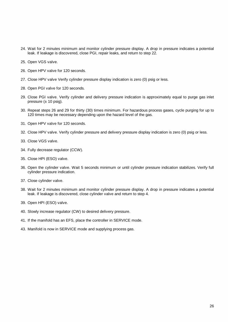
24. Wait for 2 minutes minimum and monitor cylinder pressure display. A drop in pressure indicates a potential leak. If leakage is discovered, close PGI, repair leaks, and return to step 22.
25. Open VGS valve. 26. Open HPV valve for 120 seconds. 27. Close HPV valve Verify cylinder pressure display indication is zero (0) psig or less. 28. Open PGI valve for 120 seconds. 29. Close PGI valve. Verify cylinder and delivery pressure indication is approximately equal to purge gas inlet
pressure (± 10 psig). 30. Repeat steps 26 and 29 for thirty (30) times minimum. For hazardous process gases, cycle purging for up to
120 times may be necessary depending upon the hazard level of the gas. 31. Open HPV valve for 120 seconds. 32. Close HPV valve. Verify cylinder pressure and delivery pressure display indication is zero (0) psig or less. 33. Close VGS valve. 34. Fully decrease regulator (CCW). 35. Close HPI (ESO) valve. 36. Open the cylinder valve. Wait 5 seconds minimum or until cylinder pressure indication stabilizes. Verify full
cylinder pressure indication. 37. Close cylinder valve. 38. Wait for 2 minutes minimum and monitor cylinder pressure display. A drop in pressure indicates a potential
leak. If leakage is discovered, close cylinder valve and return to step 4. 39. Open HPI (ESO) valve. 40. Slowly increase regulator (CW) to desired delivery pressure. 41. If the manifold has an EFS, place the controller in SERVICE mode. 43. Manifold is now in SERVICE mode and supplying process gas.

27
7.4 5 Valve Manifold Overnight Shutdown Purge Proce dure 1. Close the cylinder valve. 2. If the manifold has an EFS, place the controller in PURGE mode. 3. Open process isolation valve downstream of regulator (PLI ). 4. Open LPI valve. 5. Open VGI valve. 6. Open VGS valve. 7. Open HPV valve for 90 seconds 8. Close HPV. Verify cylinder and delivery pressure indication is zero (0) psig. 9. Close HPI (ESO) valve. 10. Wait 3 minutes minimum, then again verify cylinder pressure indication is zero (0) psig. If pressure has
increased, then cylinder valve is leaking past the seat. If cylinder valve is leaking, open the valve and close again tightly; then return to step 4. Do not proceed if cylinder valve continues to leak; contact gas supplier for assistance.
11. Open HPI (ESO) valve. 12. Fully increase regulator (CW). 13. Open HPV valve for 120 seconds. 14. Close HPV valve. Verify cylinder pressure indication is zero (0) psig or less. 15. Open PGI valve for 120 seconds. 16. Close PGI. Verify cylinder and delivery pressure indication is approximately 90 psig. 17. Repeat steps 13 thru 16 for five times. 18. Close VGI valve. 19. Close VGS valve. 20. Open PGI valve. 21. Close PGI valve. 22. Close process isolation valve downstream of regulator (PLI). 23. Verify system pressure is 75 psig minimum. 24. System is now in overnight purge mode. Continue when ready to restart manifold process gas flow. 25. Open process isolation valve downstream of regulator (PLI). 26. If system pressure is below 50 psig, check system for leaks.

28
27. Open VGS valve. 28. Open VGI valve. 29. Open HPV valve for 120 seconds. 30. Close HPV Valve. Verify cylinder and delivery pressure display indication is zero (0) psig or less. 31. Fully decrease regulator (CCW). 32. Close HPI valve. 33. Open cylinder valve. Wait 5 seconds minimum or until cylinder pressure indication stabilizes. Verify full
cylinder pressure indication. 34. Close cylinder valve. 35. Wait for 2 minutes minimum and monitor cylinder pressure display. A drop in pressure indicates a potential
leak. If leakage is discovered, close cylinder valve and perform a manifold maintenance purge procedure to repair leaks.
36. Close VGI valve. 37. Close VGS valve. 38. Close LPI valve. 39. Open HPI (ESO) valve. 40. Open cylinder valve. 41. Slowly increase regulator (CW) to desired delivery pressure. 42. Open LPI valve. 43. If the manifold has an EFS, place the controller in SERVICE mode. 44. Manifold is now in SERVICE mode and supplying process gas.

29
7.5 Automatic Switchover Operation The automatic switchover function automatically operates the final isolation valve to the process gas delivery line to shut off a manifold whose gas cylinder is nearly depleted and turn on a standby manifold whose gas cylinder is full (standby manifold must be in service ready mode). An alarm will sound to notify the operator that the empty cylinder should be replaced. Typically the automatic switchover function for 3 Valve Manual Centurion GSMs is accomplished using an AS-200. Refer to the operations manual for the AS-200 or other controller as appropriate for correct operating procedures.
30
8. GSM MAINTENANCE 8.1 Manifold Inspection 8.1.1 Pigtail connection Pigtail sealing surface should be inspected at each cylinder change for damage, scratching, wear and corrosion. If any damage is present then the pigtail should be replaced at this time. 8.1.2 Regulator Regulator operation should be verified each time a purge routine is performed. If any creep in the regulator is noticed or regulator is not supplying the pressure properly then the regulator should be replaced at this time. 8.1.3 Conical Filter Gasket (CGF) If purging of the pigtail is not able to be performed or the purging takes longer than expected then the CFG should be replaced. 8.1.4 Gauges/transducers Gauges should be evaluated each time a purge routine is performed and calibrated or replaced when necessary. Calibration should be performed at least every 6 months. 9. TROUBLESHOOTING This section describes possible causes for manifold indications caused by component failure, incorrect operation, etc. The indication observed by the operator is given and then possible failure causes. Should questions arise, contact the MTG Field Service Department for assistance in interpretation. 9.1 Manifold Indication: High Delivery Pressure Possible causes: • Defective or maladjusted pressure regulator • Defective, obstructed, maladjusted, or disconnected delivery pressure transducer/gauge • Defective analog input channel 9.2 Manifold Indication: High Manifold Pressure Dur ing Evacuation Possible causes: • Defective HPV , or VGS • Inadequate vacuum generator supply source pressure • Obstructed vacuum generator supply line • Defective or obstructed vacuum generator • Obstructed vacuum generator supply line check valve • Defective, obstructed, maladjusted, or disconnected cylinder pressure transducer/gauge 9.3 Manifold Indication: Low Manifold Pressure Duri ng Purge Possible causes: • Inadequate purge gas supply pressure • Defective purge gas check valve • Obstructed purge gas orifice

31
• Defective, obstructed, maladjusted, or disconnected cylinder pressure transducer 9.4 Manifold Indication: Low Cylinder Pressure Possible causes: • Inadequate process gas source pressure (e.g., empty cylinder) • Blocked process gas line between cylinder and GSM • Defective, obstructed, maladjusted, or disconnected cylinder pressure transducer/Gauge 9.5 Manifold Indication: Excess Flow Shutdown Possible causes: • Incorrect, defective, or disconnected excess flow switch • Broken or disconnected process gas delivery line to process equipment. • Process equipment using excess of process gas. 9.6 Manifold Indication: Low Cylinder Weight Possible causes: • Nearly-depleted cylinder • Defective cylinder scale • Improperly tared cylinder weight Disconnected cylinder scale input to GSMC 10. SERVICE POLICY Should a problem develop in the operation of a Centurion source gas manifold or other MTG equipment, we respectfully suggest reading appropriate operation manual sections. Should the problem persist, please remember that MTG Field Service is available during normal business hours (Eastern Time) to answer questions. The Field Service direct telephone number is 800 850-6231. The MTG factory toll-free telephone number is 800-850-6231; local telephone number is 215-641-2700; FAX number is 215-641-2714. Customer suggestions for service and product improvements are always appreciated.

32
11. GLOSSARY Abbreviations: n = noun; v = verb; adj. = adjective AGC (n) Auto-Guard Connection, a pneumatic device that automatically positions a metal guard
over a CGA connection when gas pressure exists in a pigtail, thereby preventing disconnection of the cylinder when the cylinder valve is open.
CFG A conical filter gasket that is installed upstream of GSM valves to filter out large particles
that can prevent manifold components from operating properly. EFS A vertical flow sensor that provides a signal when the process gas flow rate exceeds the
sensor set point. The signal is used to SHUTDOWN all manifold valves and an audible alarm alerts the user to investigate.
Enable (v) To manually or automatically accomplish preliminary steps required to make an operation
immediately invokable. MOP (n) Maximum Operating Pressure, the pressure to which a manifold can be pressurized
without exceeding the safe operating pressure ratings of its components. Synonymous with design pressure as defined by ANSI/ASME B31.3.
Proof Pressure A component test pressure considerably above the maximum operating pressure but
below the burst pressure, and that should not result in permanent deformation of the component.
PGO (n) Purge Gas Orifice, a flow-limiting orifice that is interposed in the purge gas inlet line. Purge Procedure (n) An automated procedure for replacing process or contaminant gas in the manifold space
with purge gas. This is accomplished by repeatedly pressurizing and exhausting the space with purge gas; interruptions in the procedure enable maintenance operations, leak testing, etc., to be accomplished. Several types of purge procedures are available for accomplishing different tasks.
Sensor (n) A pressure transducer, flow switch, pressure switch, or similar device that detects a
change in physical characteristics. Unit (n) The engineering unit associated with a parameter; example: psig Value (n) The number associated with a unit; example: 245.5 Valve Acronyms (n) Two - or three - letter standard designations for GSM valves, set in HELVETICA type:
- ACV = Automated Cylinder Valve; a pneumatically-actuated version of the conventional cylinder valve.
- -HPI = High Pressure Isolation Valve; when closed, isolates regulator and
downstream components from process gas source.
- HPV = High Pressure Vent Valve; when open, vents high-pressure purge gas or high-pressure process gas via vacuum generator.
- LI = Line Isolation Valve; when closed, isolates process line from LPI manifold
- LPI = Low Pressure Isolation Valve; when closed, isolates GSM from process
33
gas delivery line. This valve also performs the automatic switchover function when used with LNX controllers
- LPV = Low Pressure Vent Valve; when open, vents low-pressure purge gas or
low-pressure process gas via vacuum generator. A check valve precludes backflow of vacuum generator supply gas or high pressure process gas into the GSM via LPV.
- PBV = Purifier Bypass Valve; when closed allows process gas to bypass purifier.
When open, allows process gas to flow out of purifier.
- PGB = Purge Gas Bleed Valve; a valve that when open allows full flow of purge gas and when closed allows a small flow of purge gas. Extends equipment life by allowing a small flow of purge gas at all times, thereby lessening the chance of corrosive obstruction.
- PGI = Purge Gas Inlet Valve; when closed, isolates regulator and downstream
components from purge gas source.
- PIV = Purifier Inlet Valve; when closed allows process gas to bypass purifier. When open, allows process gas to flow through purifier.
- PLI = Process (Gas Delivery) Line Isolation Valve; when closed, isolates GSM
from process gas delivery line.
- POV = Purifier Outlet Valve; isolates purifier outlet from process panel.
- PVV = Purifier Vent Valve; allows purified gas to be sent to vent during purifier conditioning.
- VAI = Vacuum Access Isolation Valve; when closed, isolates the low-pressure
vent line from leak test equipment vacuum source. The inlet port of this valve is connected to leak test equipment during leak testing only; the inlet port is closed with a protective cap during typical operation of the GSM.
- VAP = Vacuum Access Port; port used to connect vacuum or leak test equipment
to the low-pressure GSM vent line.
- VGI = Vacuum Generator Isolation Valve; when closed, isolates the low - and high - pressure vent lines from the vacuum generator.
- VGS = Vacuum Generator Supply Valve; when open, allows vacuum generator
supply gas to enter vacuum generator venturi, producing vacuum.