Embed Size (px)
Citation preview
March 7, 2012 1
Current Transformers
Bonneville Power AdministrationSteve Laslo◦ For the Hands On Relay School (3-12)
Revision 1.1 (Basic)

March 7, 2012 2
Objective of the presentation:
For learners to increase their knowledge level of Current Transformers in the following areas:◦ Basic Theory◦ Application◦ Terminology◦ Safety Hazards◦ Safe Work Practices
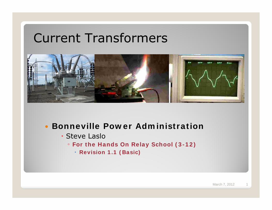
March 7, 2012 3Examples of CT’s
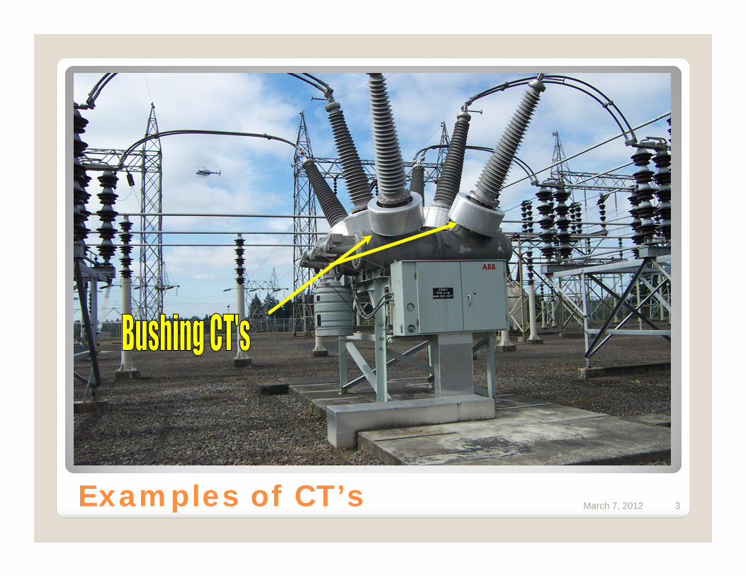
March 7, 2012 4Examples of CT’s
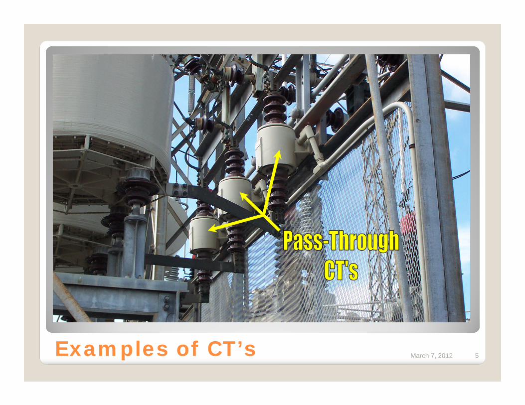
March 7, 2012 5Examples of CT’s
March 7, 2012 6
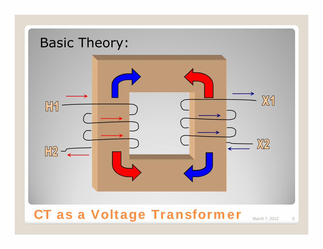
Basic Theory:
CT as a Voltage Transformer
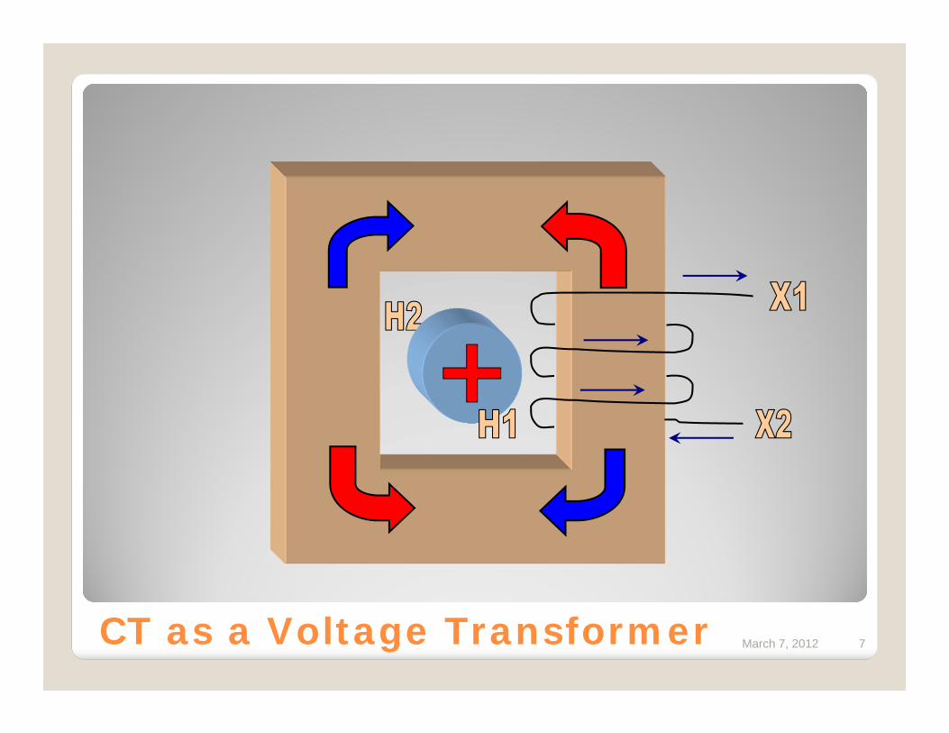
March 7, 2012 7CT as a Voltage Transformer
March 7, 2012 8
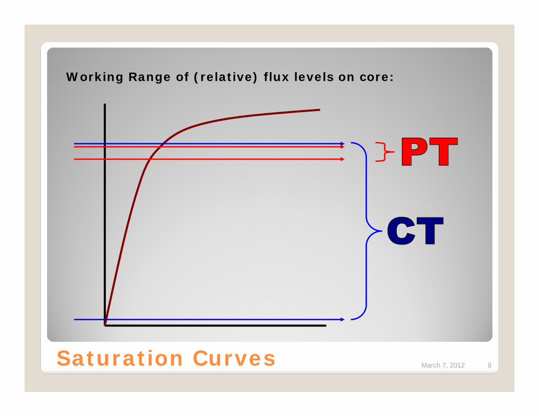
Working Range of (relative) flux levels on core:
Saturation Curves
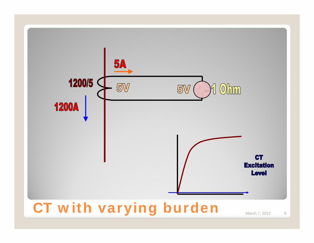
March 7, 2012 9CT with varying burden
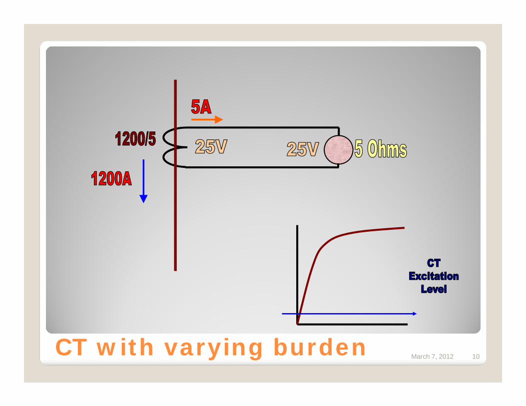
March 7, 2012 10CT with varying burden
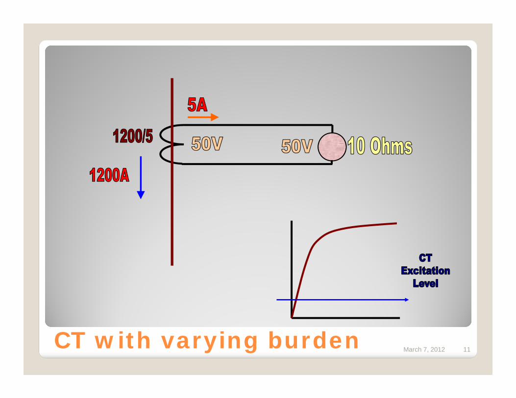
March 7, 2012 11CT with varying burden
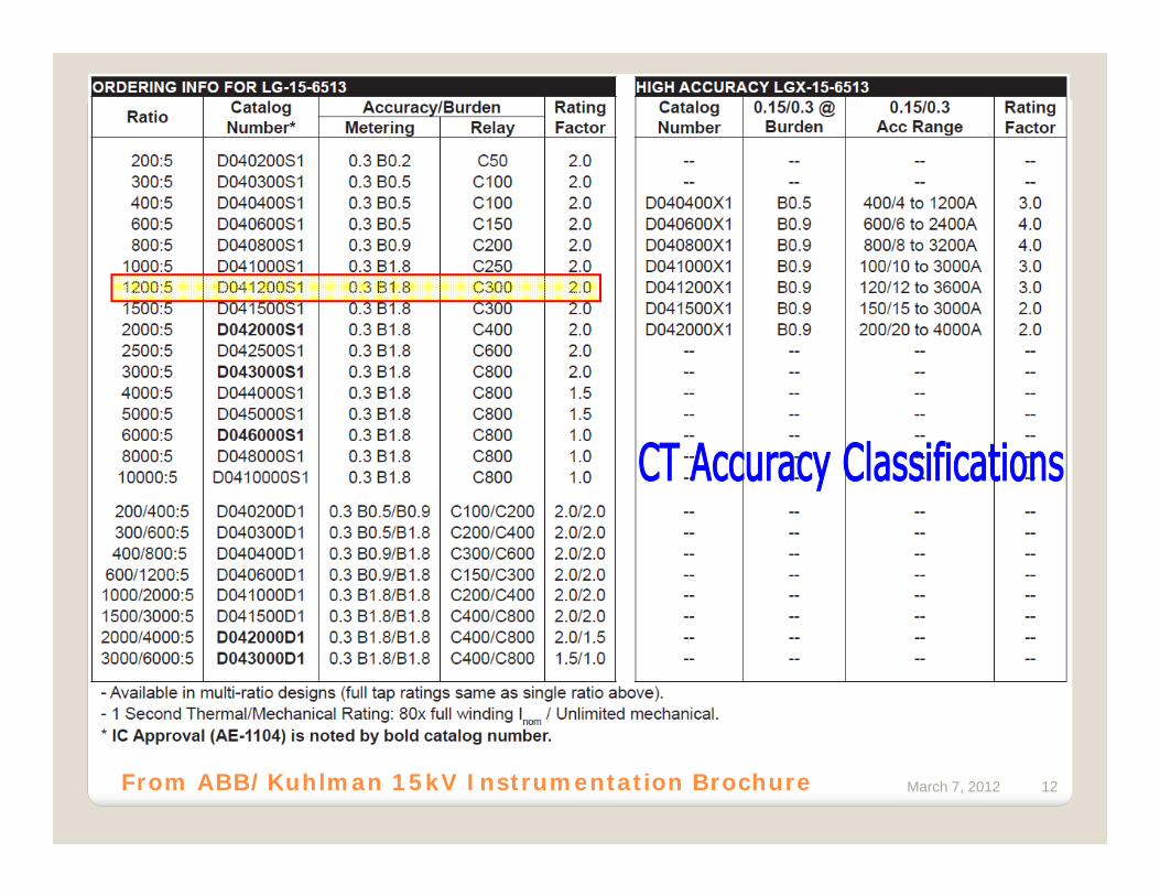
March 7, 2012 12From ABB/Kuhlman 15kV Instrumentation Brochure
March 7, 2012 13
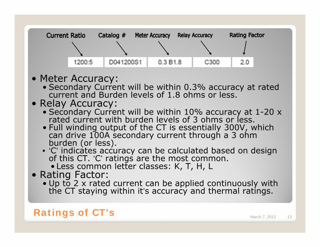
• Meter Accuracy:• Secondary Current will be within 0.3% accuracy at rated
current and Burden levels of 1.8 ohms or less.• Relay Accuracy:
• Secondary Current will be within 10% accuracy at 1-20 x rated current with burden levels of 3 ohms or less.
• Full winding output of the CT is essentially 300V, which can drive 100A secondary current through a 3 ohm burden (or less).
• ‘C’ indicates accuracy can be calculated based on design of this CT. ‘C’ ratings are the most common.• Less common letter classes: K, T, H, L
• Rating Factor:• Up to 2 x rated current can be applied continuously with
the CT staying within it’s accuracy and thermal ratings.
Ratings of CT’s
March 7, 2012 14
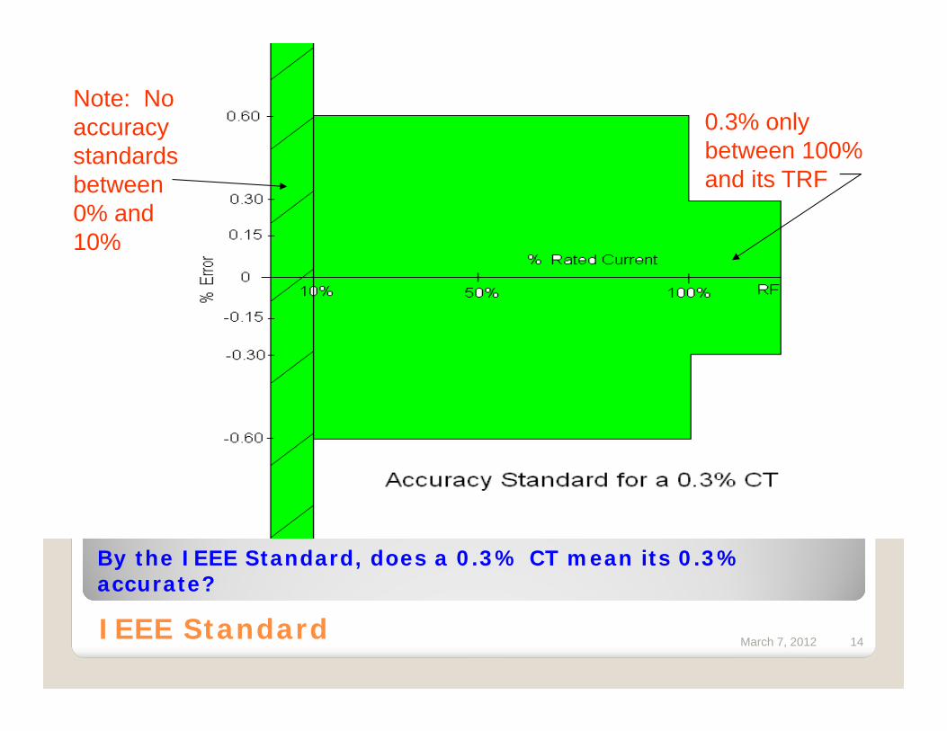
0.3% only between 100% and its TRF
Note: No accuracy standards between 0% and 10%
By the IEEE Standard, does a 0.3% CT mean its 0.3% accurate?
IEEE Standard
March 7, 2012 15
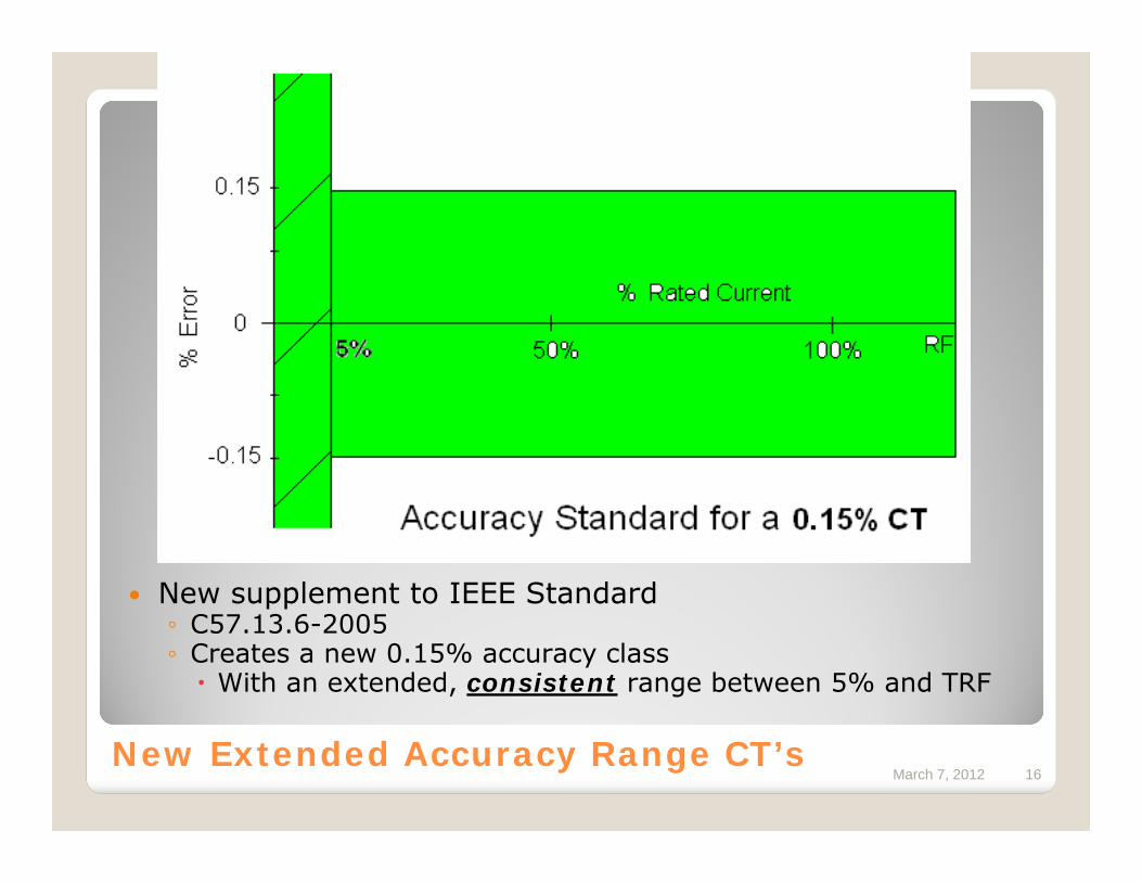
March 7, 2012 16New Extended Accuracy Range CT’s
New supplement to IEEE Standard◦ C57.13.6-2005◦ Creates a new 0.15% accuracy class
With an extended, consistent range between 5% and TRF
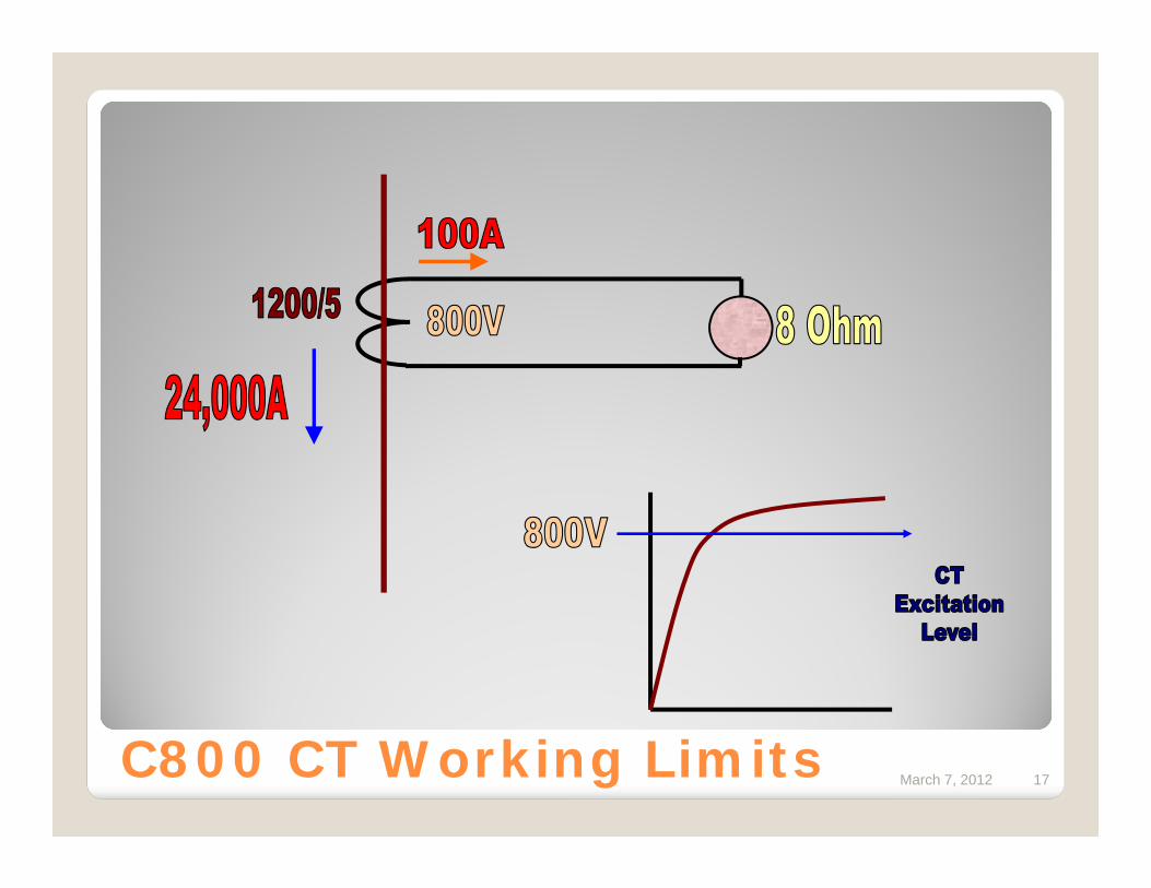
March 7, 2012 17C800 CT Working Limits
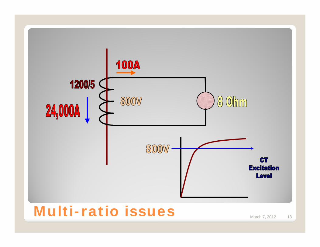
March 7, 2012 18Multi-ratio issues

March 7, 2012 19Multi-ratio issues
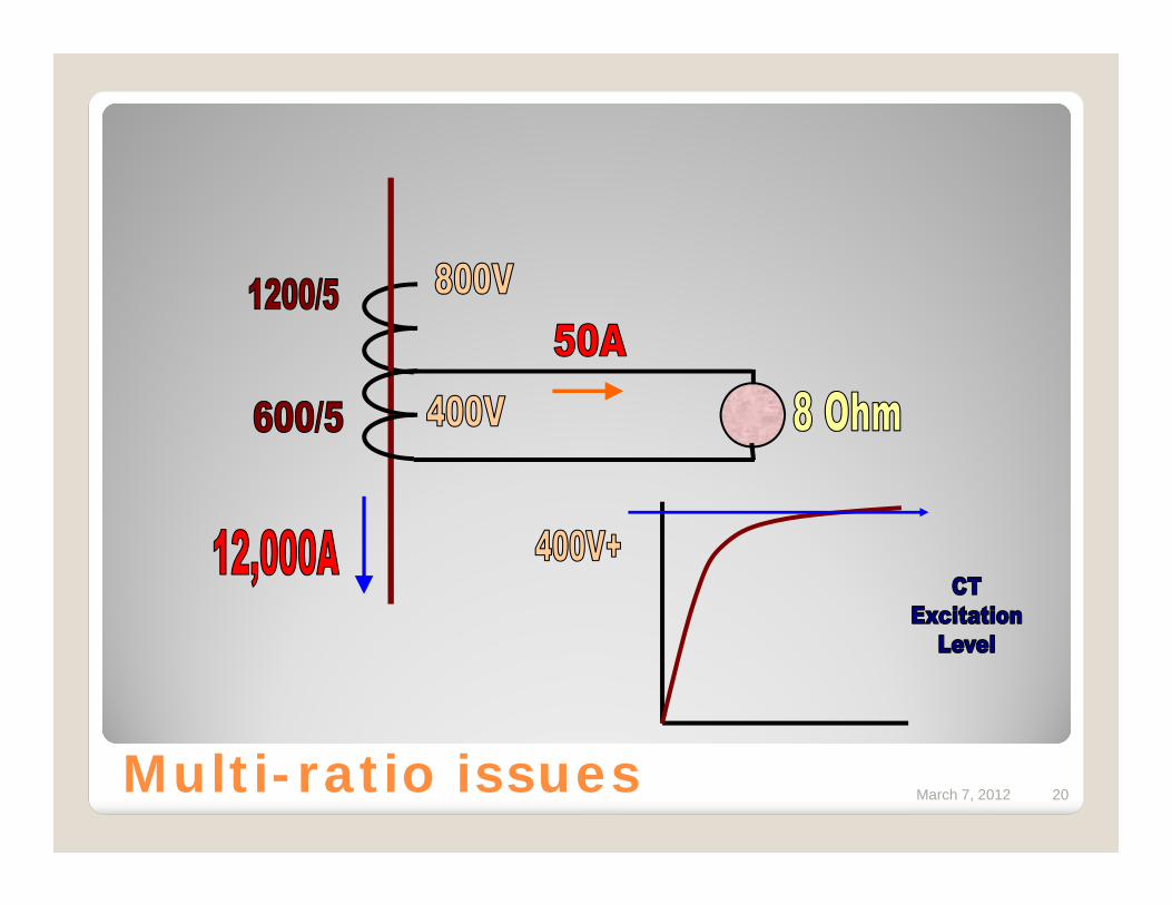
March 7, 2012 20Multi-ratio issues
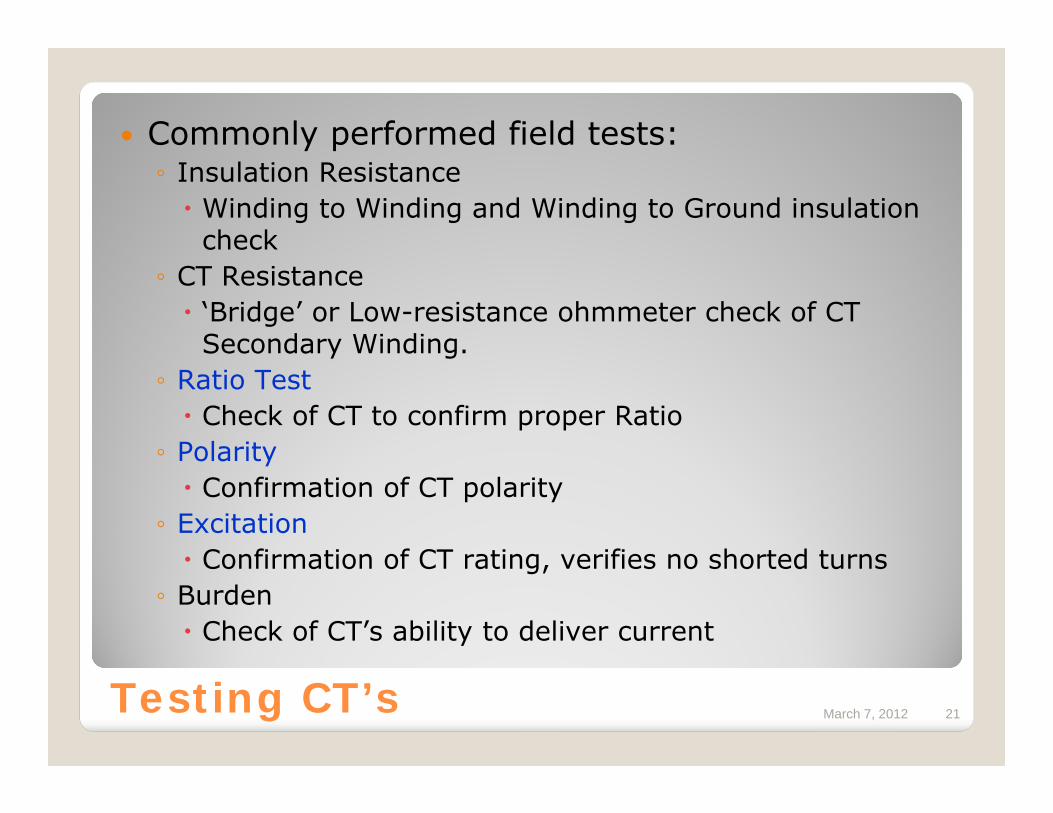
March 7, 2012 21Testing CT’s
Commonly performed field tests:◦ Insulation Resistance
Winding to Winding and Winding to Ground insulation check
◦ CT Resistance‘Bridge’ or Low-resistance ohmmeter check of CT Secondary Winding.
◦ Ratio TestCheck of CT to confirm proper Ratio
◦ PolarityConfirmation of CT polarity
◦ ExcitationConfirmation of CT rating, verifies no shorted turns
◦ BurdenCheck of CT’s ability to deliver current
March 7, 2012 22Testing CT’s
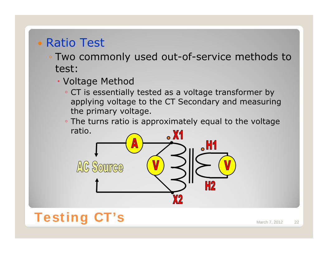
Ratio Test◦ Two commonly used out-of-service methods to test:
Voltage Method◦ CT is essentially tested as a voltage transformer by
applying voltage to the CT Secondary and measuring the primary voltage.◦ The turns ratio is approximately equal to the voltage
ratio.
March 7, 2012 23Testing CT’s
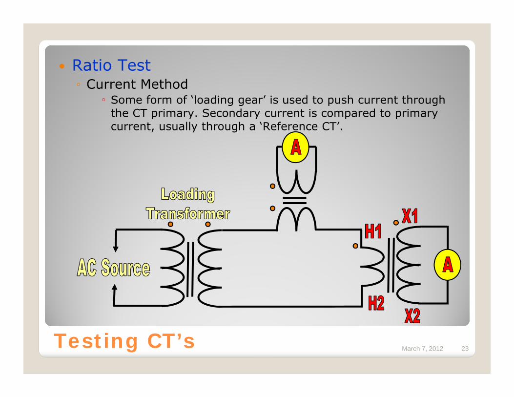
Ratio Test◦ Current Method
◦ Some form of ‘loading gear’ is used to push current through the CT primary. Secondary current is compared to primary current, usually through a ‘Reference CT’.
March 7, 2012 24Testing CT’s
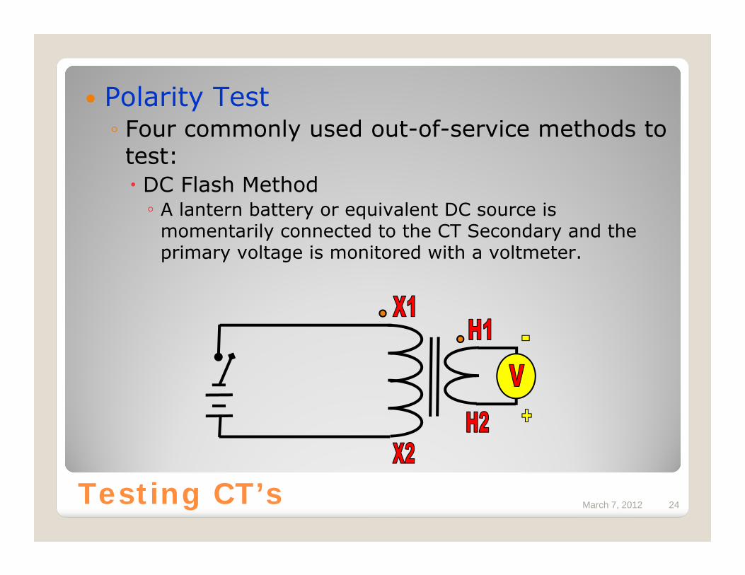
Polarity Test◦ Four commonly used out-of-service methods to test:
DC Flash Method◦ A lantern battery or equivalent DC source is
momentarily connected to the CT Secondary and the primary voltage is monitored with a voltmeter.
March 7, 2012 25Testing CT’s
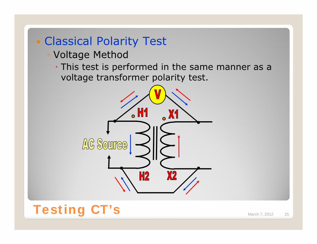
Classical Polarity Test◦ Voltage Method
This test is performed in the same manner as a voltage transformer polarity test.
March 7, 2012 26Testing CT’s
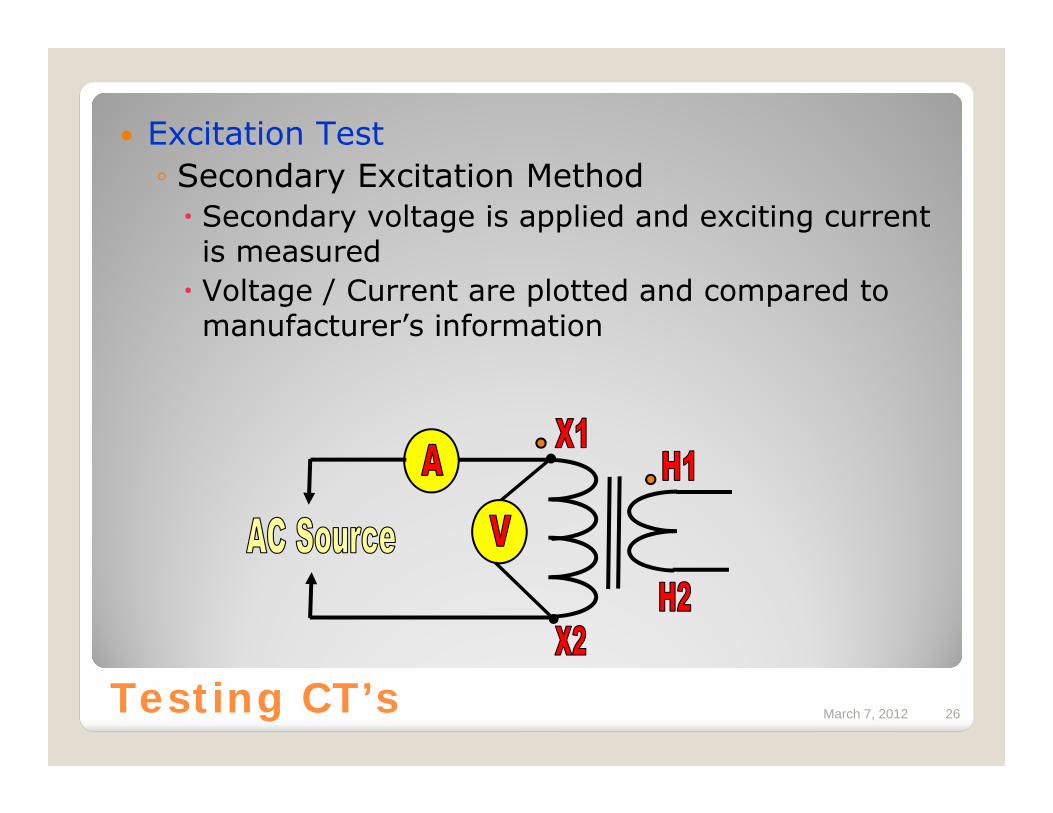
Excitation Test◦ Secondary Excitation Method
Secondary voltage is applied and exciting current is measuredVoltage / Current are plotted and compared to manufacturer’s information
March 7, 2012 27Testing CT’s
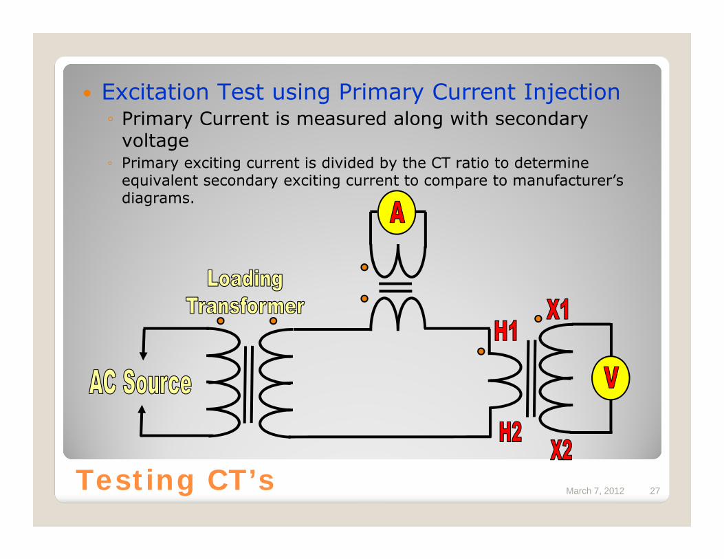
Excitation Test using Primary Current Injection◦ Primary Current is measured along with secondary
voltage◦ Primary exciting current is divided by the CT ratio to determine
equivalent secondary exciting current to compare to manufacturer’s diagrams.
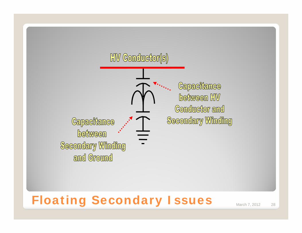
March 7, 2012 28Floating Secondary Issues
March 7, 2012 29
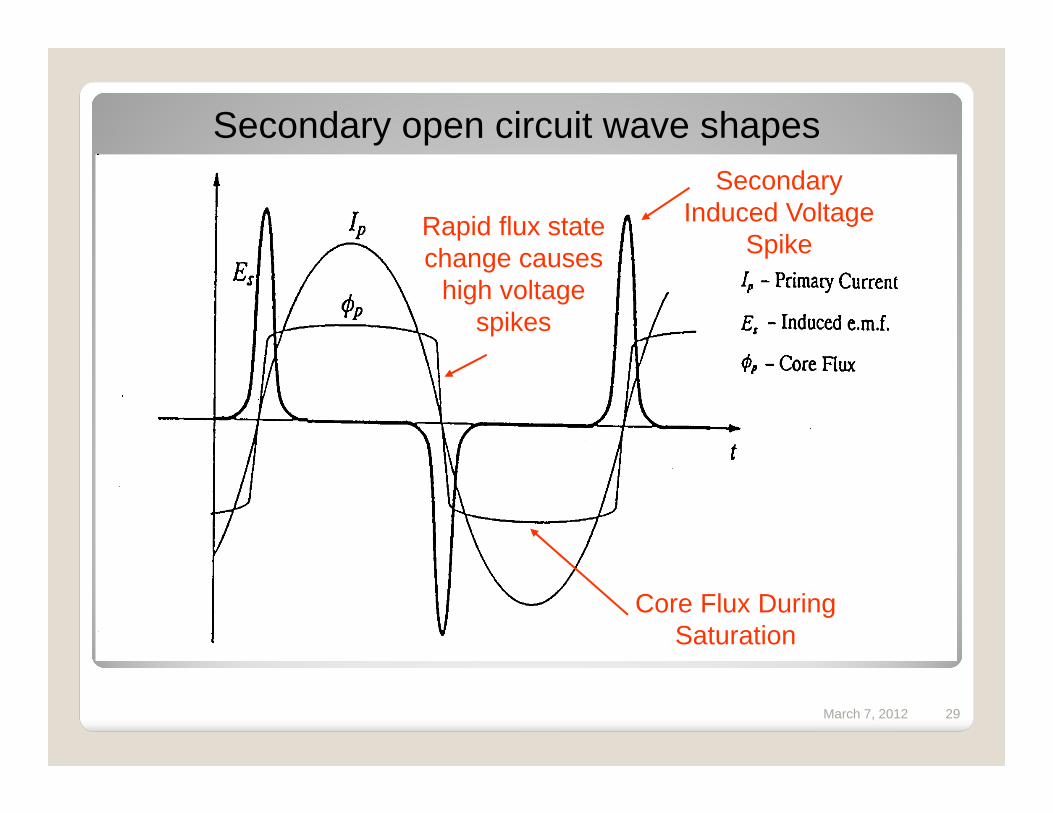
Secondary Induced Voltage
Spike
Core Flux During Saturation
Secondary open circuit wave shapes
Rapid flux state change causes
high voltage spikes

March 7, 2012 30
Demonstration of high voltagesTo verify that such voltages can be produced
we will spark a pre-set gap at 1,000 volts
Click Video to Run
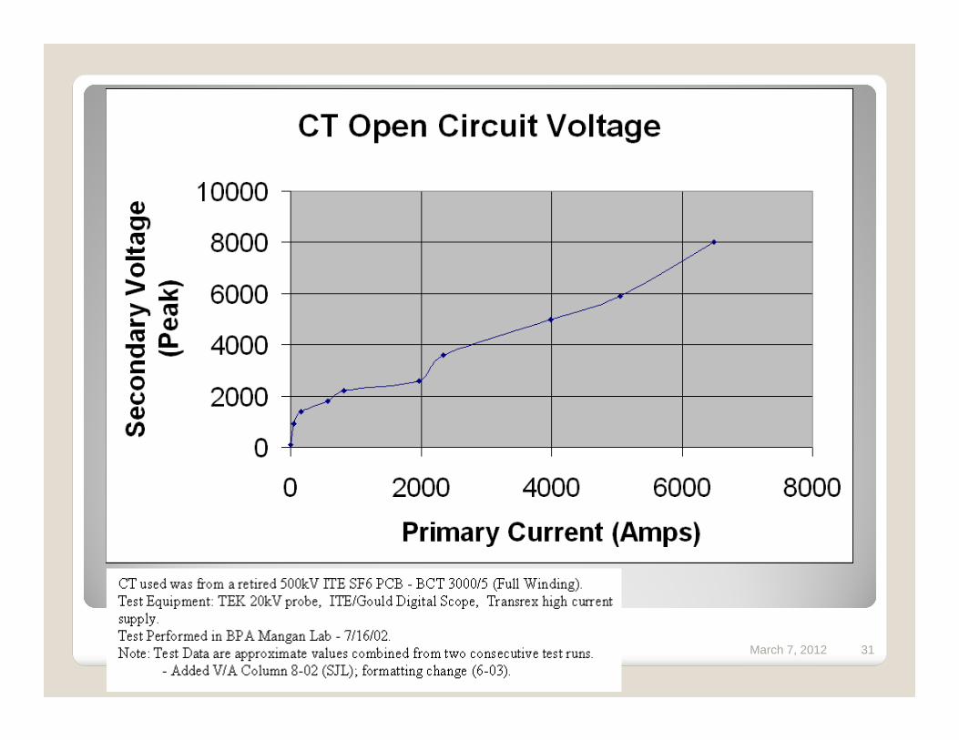
March 7, 2012 31
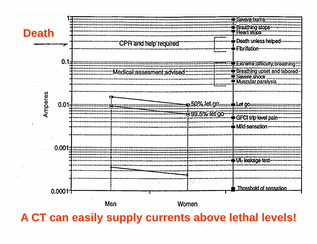
March 7, 2012 32A CT can easily supply currents above lethal levels!
Death
March 7, 2012 33
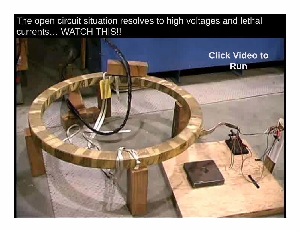
The open circuit situation resolves to high voltages and lethal currents… WATCH THIS!!
Click Video to Run
March 7, 2012 34
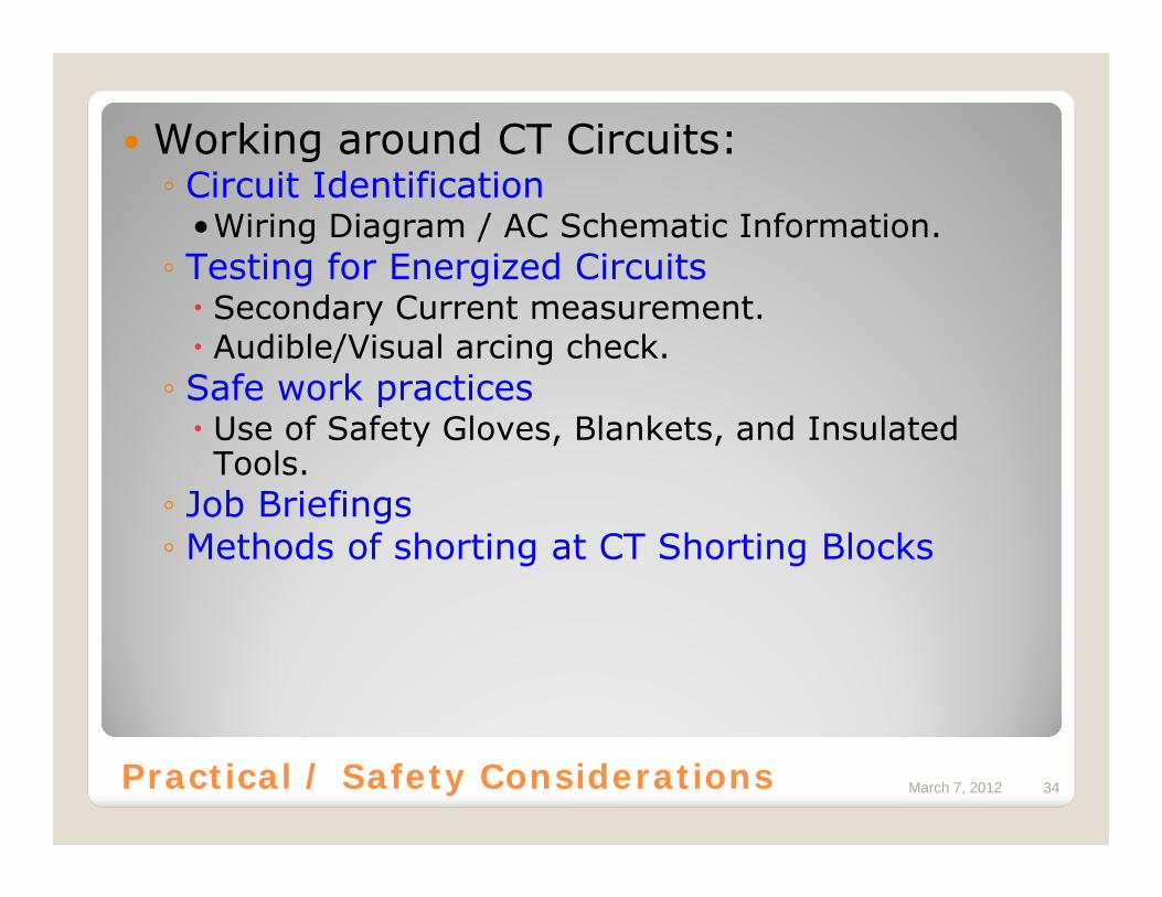
Working around CT Circuits:◦ Circuit Identification
•Wiring Diagram / AC Schematic Information.◦ Testing for Energized Circuits
Secondary Current measurement.Audible/Visual arcing check.
◦ Safe work practicesUse of Safety Gloves, Blankets, and Insulated Tools.
◦ Job Briefings◦ Methods of shorting at CT Shorting Blocks
Practical / Safety Considerations
March 7, 2012 35Circuit Identification
Circuit Identification was a primary factor in a CT accident at BPA.◦ CT leads were lifted on the wrong terminal block. Instead of being a circuit that was ’shorted’ and isolated, the circuit had live current flowing.
If you aren’t 100% sure of the identity and function of the circuit you are about to work on, don’t work on it – research and get assistance if necessary until you are… Circuit Identification is an important part of safe CT work.
March 7, 2012 36
Most utilities have standards for wiring specific circuits like those associated with CT’s and/or PT’s.◦ Use your knowledge of your company’s standards to help
identify CT circuits so that you can treat them appropriately. When in doubt – research until you are sure.
Example BPA standard for CT’s:◦ Normally Color Coded on BPA run cabling:
Black (1A) – A-PhaseGreen (2A) – B-PhaseRed (3A) – C-PhaseWhite (0A) – CT Common / Neutral
◦ Normally designated 1A, 2A, 3A, and 0A (if Wye-connected)
Circuit Identification
March 7, 2012 37
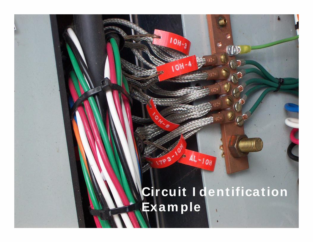
Circuit Identification Example
March 7, 2012 38
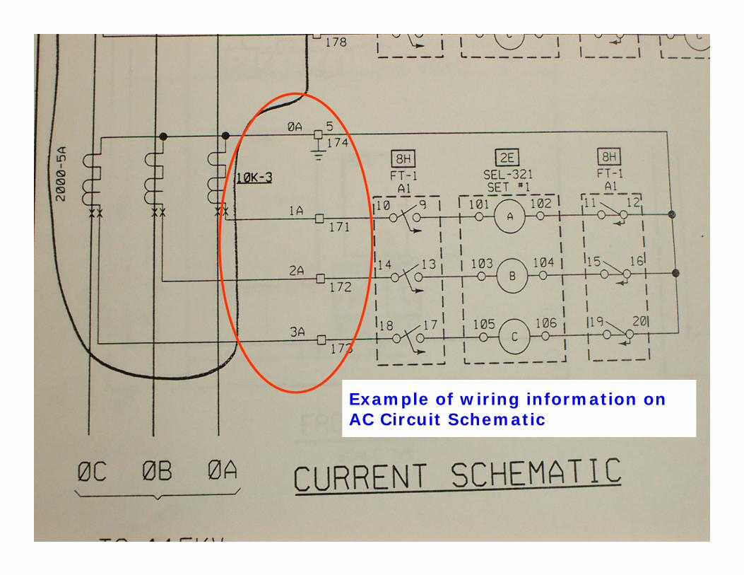
Wiring Diagrams and/or Layout Prints should show actual placement of Terminal Blocks seen on Schematic Diagrams.Schematic Diagrams show Circuit Functionality and may have some Wiring Diagram information shown on them.Schematics and Wiring Diagrams should agree with each other.Your company may have standards for typical CT configurations that may aid in the identification process.
Circuit Identification
March 7, 2012 39
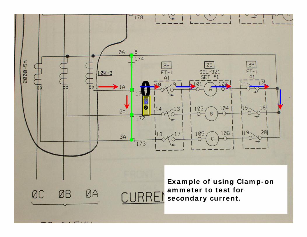
Example of wiring information on AC Circuit Schematic

March 7, 2012 40
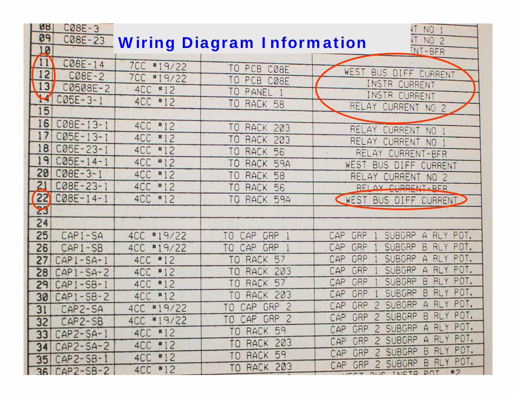
Wiring Diagram Information
Example of ‘Clues’ that wiring is part of a CT Circuit (continued on next page).
March 7, 2012 41
Wiring Diagram Information
March 7, 2012 42
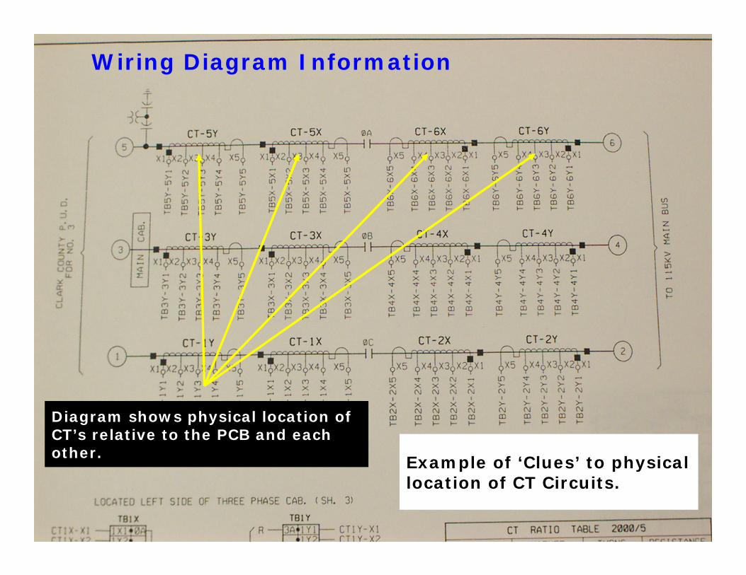
Wiring Diagram Information
Example of ‘Clues’ to physical location of CT Circuits.
Diagram shows physical location of CT’s relative to the PCB and each other.
March 7, 2012 43
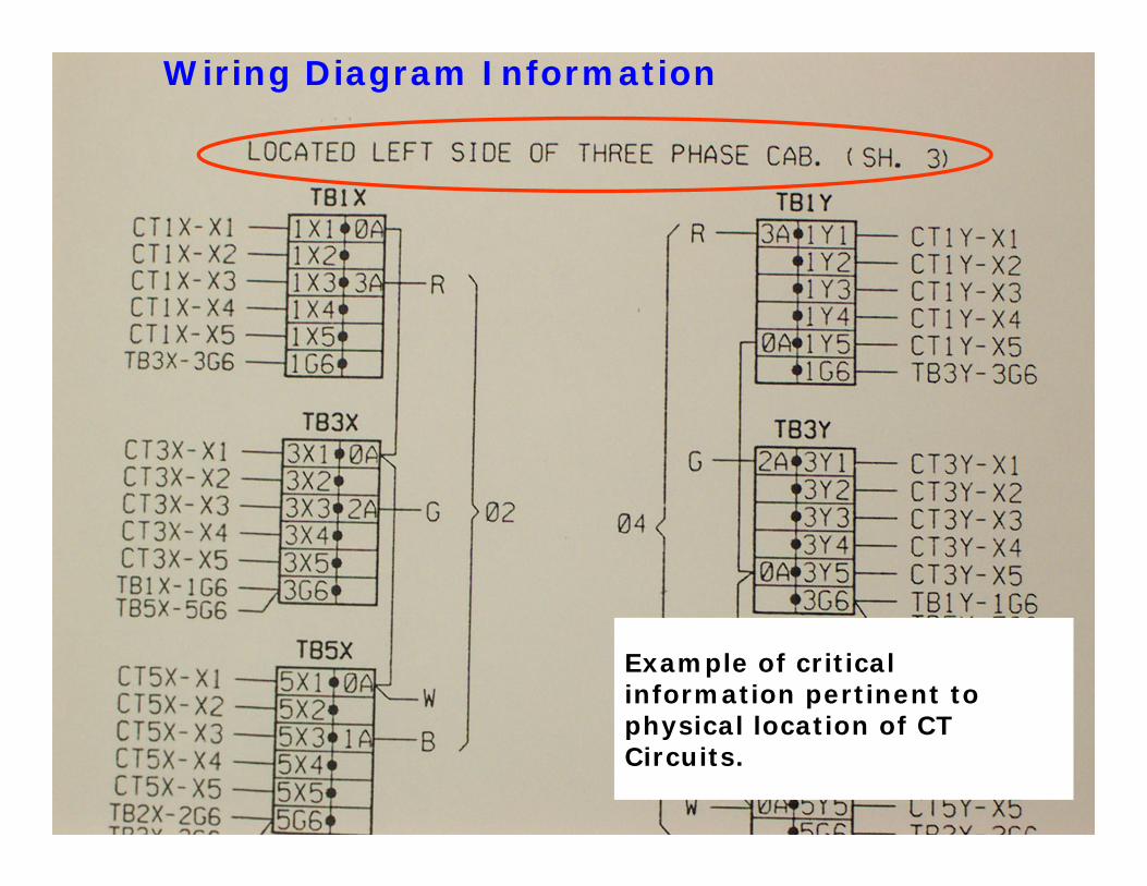
Wiring Diagram Information
Example of critical information pertinent to physical location of CT Circuits.
March 7, 2012 44
Example of using Clamp-on ammeter to test for secondary current.
March 7, 2012 45
CT Secondary Wires should be lifted slowly while listening for arcing as a final verification check.The visual/audible Arcing Check is also not 100% reliable as a test for an open-circuit CT condition.◦ In brightly lit and/or noisy areas, it may be difficult to detect the arcing condition.◦ With low values of CT secondary current, there may be little-to-no arcing when wiring is lifted.
Visual/Audible Arcing Check
March 7, 2012 46
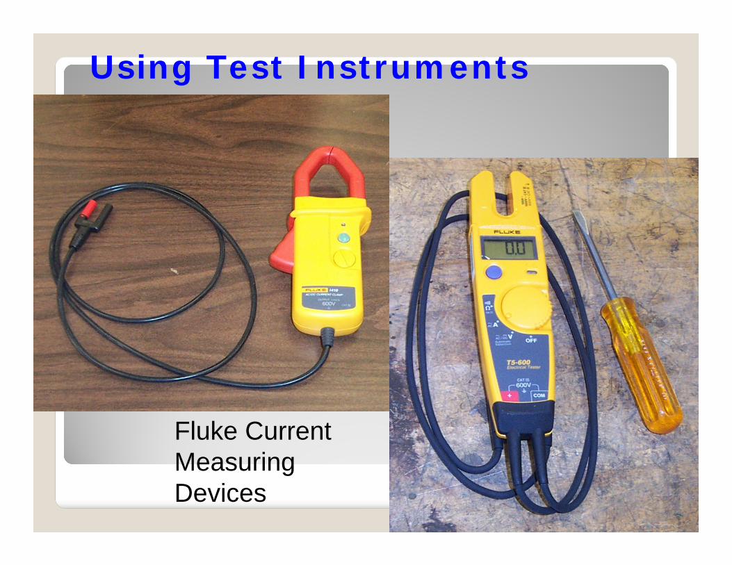
Fluke Current Measuring Devices
Using Test Instruments
March 7, 2012 47
Make sure to check the Current Test Instrument on a known circuit first, then the unidentified circuit, then the known circuit again, just like voltage test devices…
◦ Verify test instrument operation before relying on it’s results.
Using Test Instruments
March 7, 2012 48
Another item to consider when using normal hand-tools or placing your fingers on secondary wiring insulation is whether the insulation between you and the secondary conductor is truly adequate to protect you from the possible voltages a CT can produce on the secondary wiring.
If that insulation is normally rated at 600VAC or 1000VAC, are you protected from voltages that can have peaks well over 4kV?Can that screwdriver protect you from that same voltage? It’s going to be directly connected to the conductor as you remove that screw on the termination block…
Safe Work Practices
March 7, 2012 49
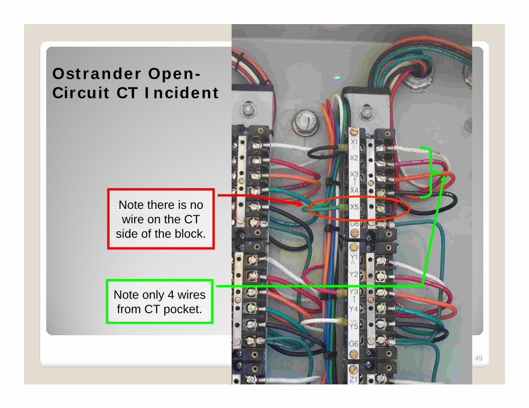
Ostrander Open-Circuit CT Incident
Note only 4 wires from CT pocket.
Note there is no wire on the CT
side of the block.
March 7, 2012 50
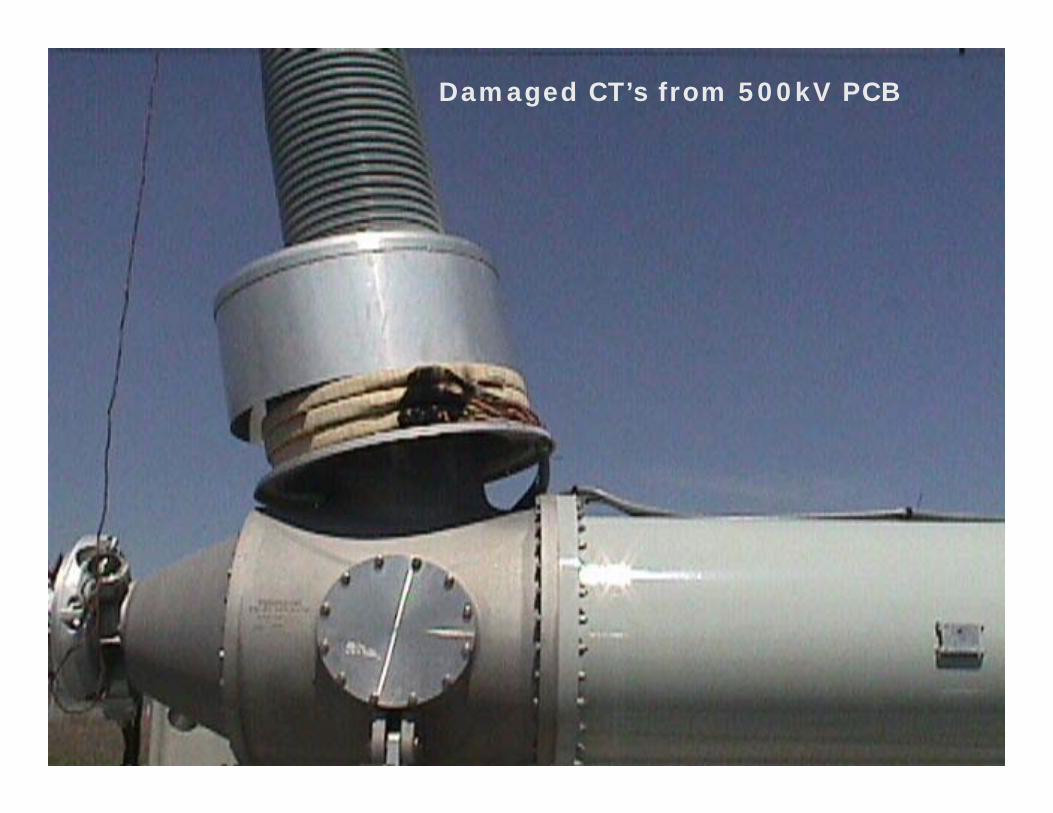
Damaged CT’s from 500kV PCB
March 7, 2012 51
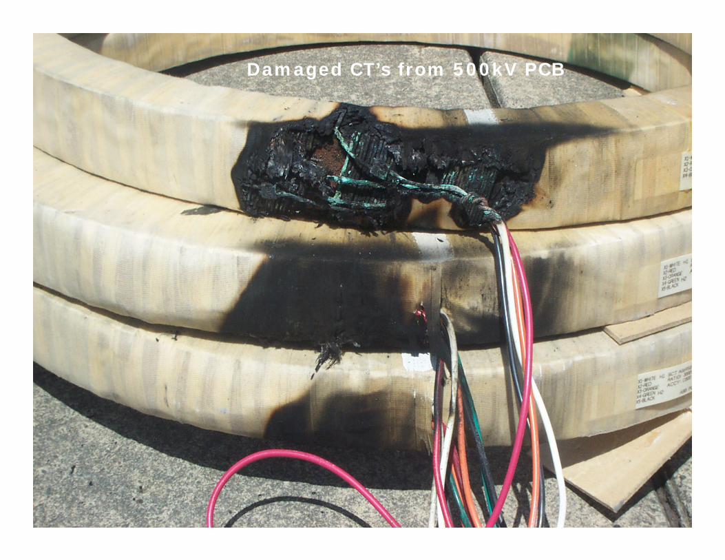
Damaged CT’s from 500kV PCB
March 7, 2012 52
Care should be taken to keep yourself from becoming a possible current path for the CT Circuit should it become open-circuited.
◦ Since CT Circuits are very often grounded (Wye), if you are touching Termination Frames or Relay Racks you may become part of the current path if you contact the CT conductor during an open-circuit incident.
Safe Work Practices
March 7, 2012 53
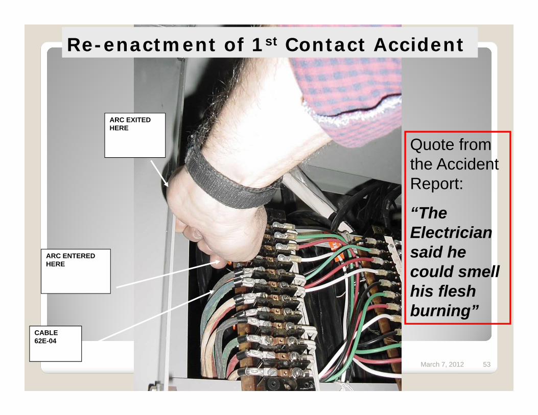
ARC EXITED HERE
ARC ENTERED HERE
CABLE62E-04
Re-enactment of 1st Contact Accident
Quote from the Accident Report:
“The Electrician said he could smell his flesh burning”

March 7, 2012 54
Sample items that can be covered at a Job Briefing or ‘Tailgate’:◦ Hazards associated with the Job.◦ Work Procedures.◦ Special Precautions.◦ Energy Source Controls◦ Personal Protective Equipment.◦ Clearances, Work Permits, Hold Orders
Job Briefings

March 7, 2012 55
Click Video
to Run
CT Open-Circuit Secondary Arcing
March 7, 2012 56
When shorting CT secondaries at CT Shorting Blocks, care must be taken to properly short the CT Circuit.
Depending on the connection made at the block it may take anywhere from 2 to 6 shorting screws to fully short the CT secondaries.
CT Shorting Blocks
March 7, 2012 57
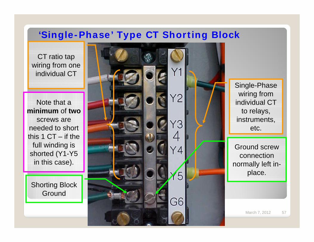
‘Single-Phase’ Type CT Shorting Block
CT ratio tap wiring from one individual CT
Shorting Block Ground
Single-Phase wiring from
individual CT to relays,
instruments, etc.
Ground screw connection
normally left in-place.
Note that a minimum of two
screws are needed to short this 1 CT – if the
full winding is shorted (Y1-Y5
in this case).
March 7, 2012 58
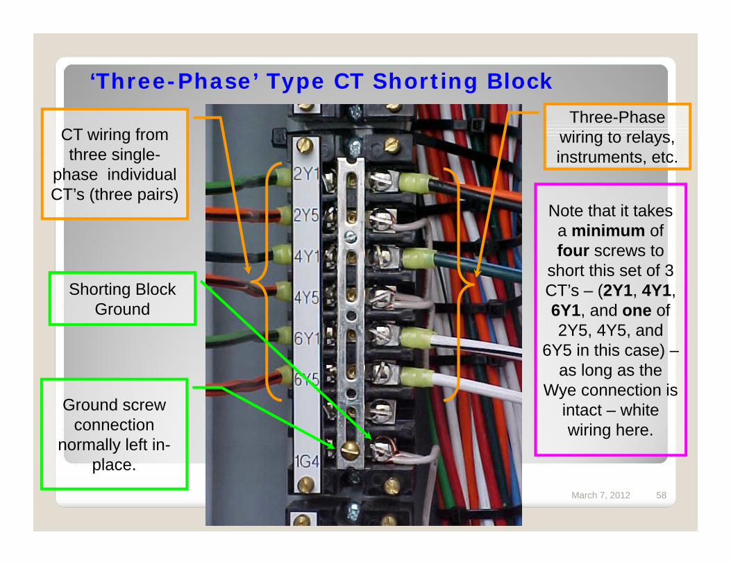
‘Three-Phase’ Type CT Shorting Block
CT wiring from three single-
phase individual CT’s (three pairs)
Shorting Block Ground
Three-Phase wiring to relays, instruments, etc.
Ground screw connection
normally left in-place.
Note that it takes a minimum of four screws to
short this set of 3 CT’s – (2Y1, 4Y1, 6Y1, and one of 2Y5, 4Y5, and
6Y5 in this case) –as long as the
Wye connection is intact – white wiring here.
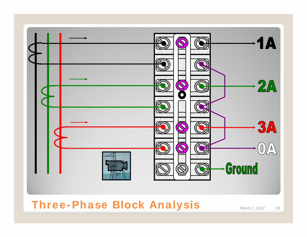
March 7, 2012 59Three-Phase Block Analysis

March 7, 2012 60
Questions?