Embed Size (px)
Citation preview

3D DDCC -Gmsh

How to meshing
1. Download the t1.geo in the tutorial.
2. Execute on the Gmsh
3. File > Open > t1.geo

How to meshing
4. Mesh
5. t1.msh (as an input for 3D DDCC )
(1)
(2)
(3)

How to meshing
• If modified the code in .geo file.
• Back to the step 3.
(1)
(2)

Basic concept
• Point/ Line/ Plane/ Volume
• t1.geo
• Point(1) = {0, 0, 0, lc};
• Try to modified the ’lc’

Basic concept
• For a cube:
– Point
– Line
– Plane
– Volume
• The volume is an unit element for 3D DDCC
• See example1.geo

Basic concept
1. Point(11) = {0, 0, 0, la};2. Line(11) = {11,12} ;3. Transfinite Line{11}=11;
Transfinite Line{11}=11 Using Bump Bup; Transfinite Line{11}=11 Using Progression Pro;
4. Line Loop(1) = {11,12,13,14} ;5. Plane Surface(11) = {1} ;6. Transfinite Surface{11};7. Surface Loop(11)={11,22,33,44,55,66} ;8. Volume(1) = {11};9. Transfinite Volume(1);

Extrude
• Simple method to model a 3D structure.
• See example2.geoExtrude {0, 0, 1} { Surface{11}; Layers{ {1,1}, {0.5,1.0} }; }

Extrude
How to know the volume and surface number of volume which is made by extrusion.
(1)
(2)
(3)
Step 1: turn off the extra mesh for high speed.
(4)


Extrude
• Or using the code to show numbers (example2.geo)
Printf("volume-number");Printf("volume1=%f",out1[1]);Printf("volume2=%f",out2[1]);Printf("volume3=%f",out3[1]);
Printf("surface-number");Printf("volume3=%f",out3[0]);

Perform the 3D meshing

Save the mesh file
The file should be saved as exampl2.msh

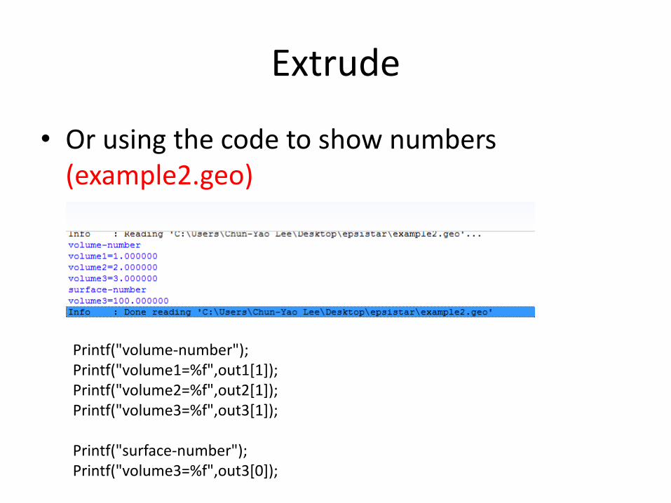
3D-DDCC GUI Interface TutorialAfter Extracted the package, you should be able to find these files
Please use Matlab to execute ddcc_3d.m or Run ddcc_3d-win64.exe / ddcc_3d-win32.exe
3D-ddcc stand alone main program
Without GUI, the 3D-ddcc.exe still can workFor example3D-ddcc-win64.exe Project_1.inp


1
2
3


Surface 11
Surface 55
Surface 43

Volume 1
Volume 2
Volume 3

Surface 100
Surface 11


12

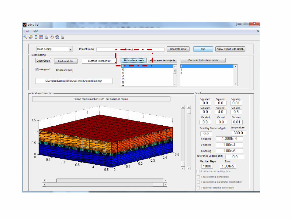
1st Step• Decide the Material• Choose the Alloy composition• Input the doping and activation energy • Input the impurity density
2nd Step 1. Press the parameter generation2. The program will generate Ec, bandoffset ratio, effective mass, mobility,
suggested radiative and nonradiative lifetime, polarization, etc. 3. You must double check the parameter generated by the programs and check to
any value you feel comfortable! These generated parameters does not mean it is the best parameters. !!! ( We are not responsible for any error generated by this GUI program)
4. After Changing the parameters by your self. DON’T PRESS “parameter generation” since all changes will be reset if you press this button.
If you want to run with Auger or generation, you need to fill in the coefficient by yourself.

Scaling of Gmsh dimension:
Extremely important !
In the gmsh program, of course we can mesh the structure with the unit of cm. However, in semiconductor or LED cases, the z-dimension is much smaller and x-y dimension is much bigger.
Therefore, it is not easy to view the structure and the Gmsh program might not be able to give a suitable meshing.
Therefore, we can enlarge the x,y, and z dimension in Gmsh for a better viewing. Then ask the 3D-DDCC program to scaling down the mesh file to a adequate size.

*.out -> The conduction potential Ec*.np -> The electron and hole density*.UNR -> The radiative and nonradiatverecombination*.nda -> The activated doping density*.Jn -> 3D electron current vector information
*.Jp -> 3D hole current vector information*.Jns -> Absolute value of electron*.Jps -> Absolute value of hole*.T -> Temperature*.info -> text file, some result information*.E -> The electric field*.Auger -> Auger recombination rate distribution
Note: The data size of 3D result (real structure) is quite large. Therefore, all results are save separately. Otherwise the Gmsh will crash easily.

Plot of Conduction band Ec

Merge *.np file to plot electron and hole density
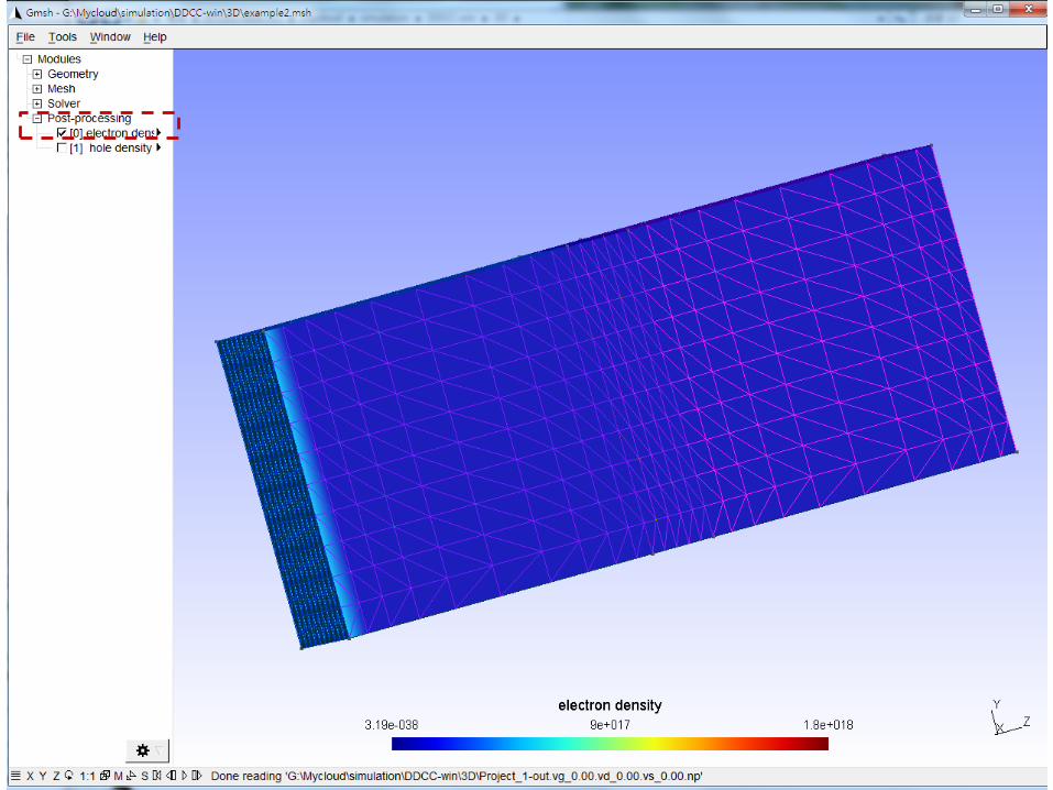


Merge *.Unr file to plot radiative and nonradiatve recombination


Appendix
The function for using extra special shape to define the area.

instr(2:18) == 'extraElBoundaries‘ not 'extraElBoundary‘
For i=1:n read(unosp, * , iostat= state) mshelboun%extrasurfacenum(i), mshelboun%extratypes(i),mshelboun%extravalue(i), &
mshelboun%extrashape(i) ,mshelboun%extrarange(1,i) ,mshelboun%extrarange(2,i) ,mshelboun%extrarange(3,i) , &mshelboun%extrarange(4,i) ,mshelboun%extrarange(5,i) ,mshelboun%extrarange(6,i) ,mshelboun%extrarange(7,i) &,mshelboun%extrarange(8,i) ,mshelboun%extrarange(9,i) ,mshelboun%extrarange(10,i) ,mshelboun%extrarange(11,i) ,msh
elboun%extrarange(12,i)End
$extraElBoundaries347 2 0.1 3 1.0 1.0 0.0 1.0 100.0 0.0 100.0 100.0 0.0 0.0 0.0 0.047 2 0.1 2 50.0 50.0 0.0 24.0 0.0 0.0 0.0 0.0 0.0 0.0 0.0 0.047 2 0.1 221 50.0 50.0 0.0 40.0 30.0 1.0 1.0 0.0 30.0 0.0 0.0 0.0

Shape =1 12 elements call el(1)……el(12) el(7) – el(12) is not used.
(el(1),el(2),el(3))
(el(4),el(5),el(6))

(El(1),el(2),el(3))
Shape =2 12 elements call el(1)……el(12) el(7) – el(12) is not used.
R = el(4)

(El(1),el(2),el(3))
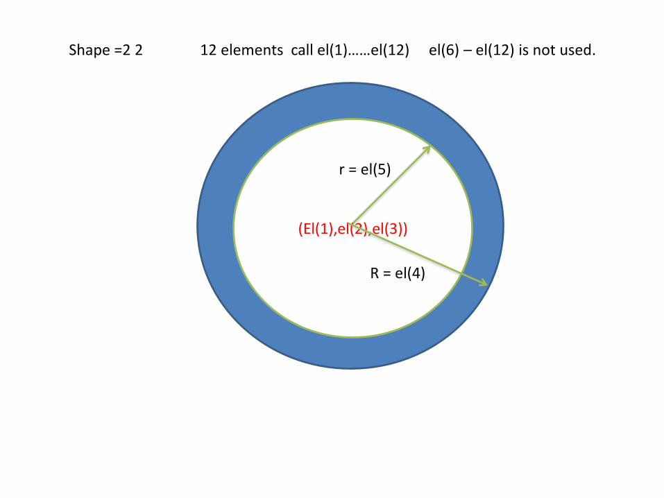
Shape =2 2 12 elements call el(1)……el(12) el(6) – el(12) is not used.
r = el(5)
R = el(4)
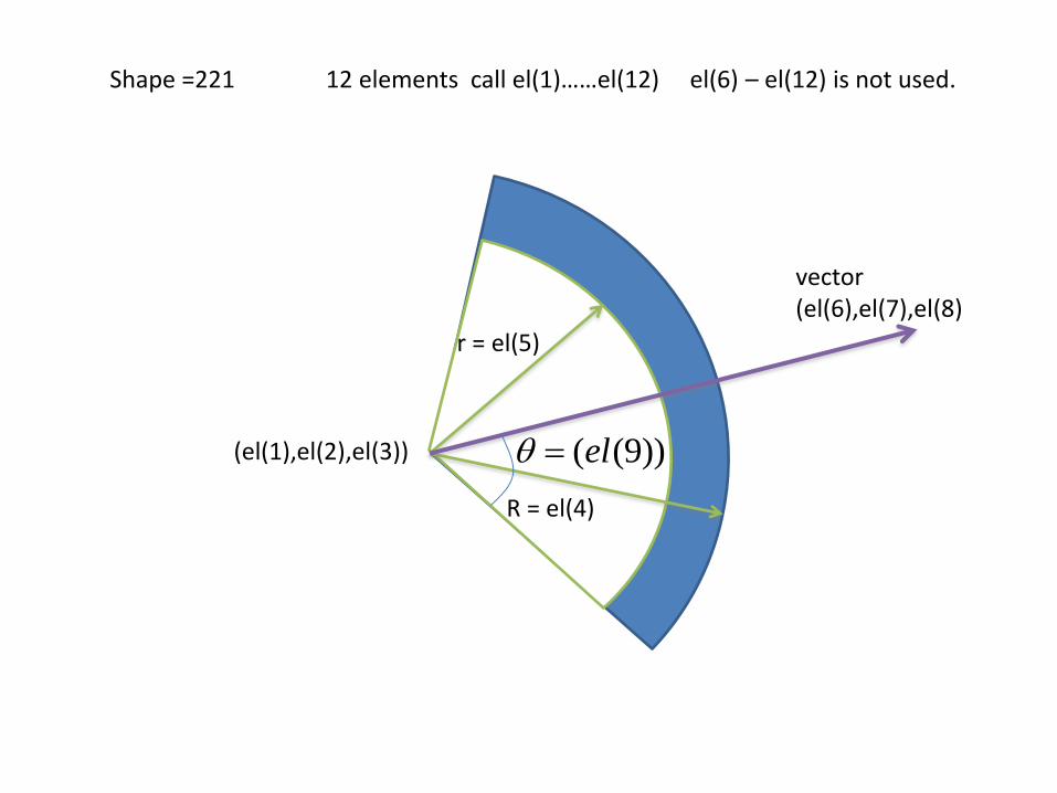
Shape =221 12 elements call el(1)……el(12) el(6) – el(12) is not used.
r = el(5)
R = el(4)
vector(el(6),el(7),el(8)
))9((el(el(1),el(2),el(3))

(El(5),el(6),el(7))
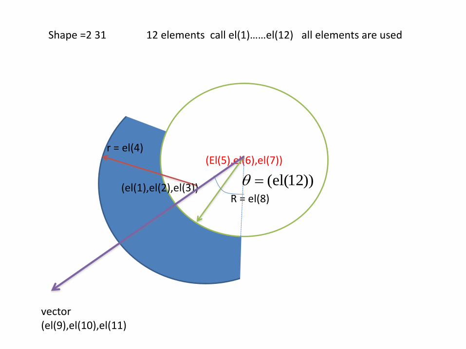
Shape =2 31 12 elements call el(1)……el(12) all elements are used
r = el(4)
R = el(8)(el(1),el(2),el(3))
vector(el(9),el(10),el(11)
))12(el(

(el(1),el(2),el(3))
(el(4),el(5),el(6)) (el(7),el(8),el(9))
Shape =3 12 elements call el(1)……el(12) el(10) – el(12) is not used.

(el(1),el(2),el(3))
(el(4),el(5),el(6))
(el(7),el(8),el(9))
Shape =4 12 elements call el(1)……el(12)
(el(10),el(11),el(12))
Please make sure that this four points are on the same plane!!!!! Or else, please use two triangles

(el(1),el(2),el(3))
(el(4),el(5),el(6))
(el(7),el(8),el(9))
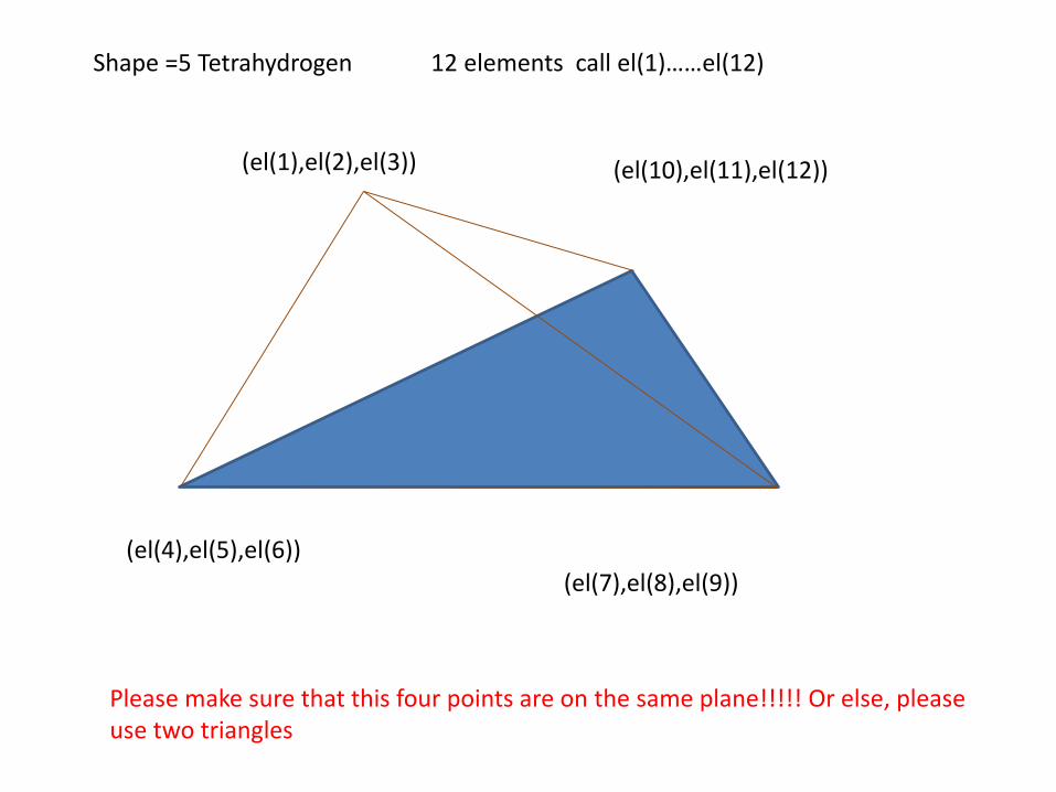
Shape =5 Tetrahydrogen 12 elements call el(1)……el(12)
(el(10),el(11),el(12))
Please make sure that this four points are on the same plane!!!!! Or else, please use two triangles
(El(1),el(2),el(3))
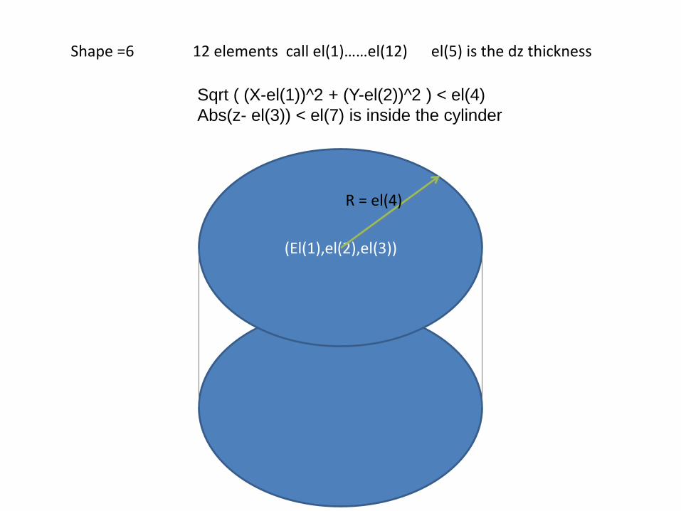
Shape =6 12 elements call el(1)……el(12) el(5) is the dz thickness
R = el(4)
Sqrt ( (X-el(1))^2 + (Y-el(2))^2 ) < el(4)
Abs(z- el(3)) < el(7) is inside the cylinder

(El(1),el(2),el(3))
Shape =6 2 12 elements call el(1)……el(12) el(7)– el(12) is not used.
r = el(5)
R = el(4)
el(5) < Sqrt ( (X-el(1))^2 + (Y-el(2))^2 ) < el(4)
Abs(z- el(3)) < el(6) is inside the cylinder

Shape =621 12 elements call el(1)……el(12) el(6) – el(12) is not used.
r = el(5)
R = el(4)
vector(el(6),el(7),el(8)
))9((el(el(1),el(2),el(3))
El(5) <Sqrt ( (X-el(1))^2 + (Y-el(2))^2 ) < el(4)
The angle el(9) refer to vector el(6), el(7), el(8)
Abs(z- el(3)) < el(10) is inside the cylinder

(El(5),el(6),el(7))
Shape =63 12 elements call el(1)……el(12) el(7)– el(12) is not used.
r = el(8)
r = el(4)
(El(1),el(2),el(3))
Sqrt ( (X-el(1))^2 + (Y-el(2))^2 ) < el(4)
Sqrt ( (X-el(5))^2 + (Y-el(6))^2 ) > el(8)
Abs(z- el(3)) < el(9) is inside the cylinder

(El(5),el(6),el(7))
Shape =6 31 12 elements call el(1)……el(12) all elements are used
r = el(4)
R = el(8)(el(1),el(2),el(3))
vector(el(9),el(10) )
))12(el(
Sqrt ( (X-el(1))^2 + (Y-el(2))^2 ) < el(4)
Sqrt ( (X-el(5))^2 + (Y-el(6))^2 ) > el(8)
The angle el(11) refer to vector x-el(9), y-el(10)
Abs(z- el(3)) < el(12) is inside the cylinder

$additionalElecshape363 el(1) …….. el(12)
$useadditionaltraps
$useadditionalAuger
$ifimpact_ion_add
read(unosp, * , iostat= state) shape, For i=1:nmshelboun%extrashape(i) ,mshelboun%extrarange(1,i) ,mshelboun%extrarange(2,i) ,mshelboun%extrarange(3,i) , mshelboun%extrarange(4,i) ,mshelboun%extrarange(5,i) ,mshelboun%extrarange(6,i) ,mshelboun%extrarange(7,i) ,mshelboun%extrarange(8,i) ,mshelboun%extrarange(9,i) ,mshelboun%extrarange(10,i) ,mshelboun%extrarange(11,i) ,mshelboun%extrarange(12,i)endFor i=1:nread(unosp,*, iostat= state) msheladd%volumenum(i),msheladd%Eg(i),msheladd%Ecoff(i),msheladd%ep(i),&
msheladd%charges(i) ,msheladd%dope(i) ,msheladd%Ea(i), msheladd%impurity(i) , &
msheladd%efmass(1,i) ,msheladd%efmass(2,i) ,msheladd%efmass(3,i) , msheladd%efmass(4,i) , &
msheladd%polz(i) ,msheladd%poly(i) ,msheladd%polx(i) , msheladd%mun(i),msheladd%mup(i), &
msheladd%taun(i),msheladd%taup(i) , msheladd%recombine(i)end

Shape =1 12 elements call el(1)……el(12) el(7) – el(12) is not used.
(el(1),el(2),el(3))
(el(4),el(5),el(6))

(El(1),el(2),el(3))
Shape =2 12 elements call el(1)……el(12) el(7) – el(12) is not used.
R = el(4)
(El(1),el(2),el(3))
Shape =2 2 12 elements call el(1)……el(12) el(6) – el(12) is not used.
r = el(5)
R = el(4)

Shape =221 12 elements call el(1)……el(12) el(6) – el(12) is not used.
r = el(5)
R = el(4)
vector(el(6),el(7),el(8)
))9((el(el(1),el(2),el(3))
(El(5),el(6),el(7))
Shape =2 31 12 elements call el(1)……el(12) all elements are used
r = el(4)
R = el(8)(el(1),el(2),el(3))
vector(el(9),el(10),el(11)
))12(el(

(el(1),el(2),el(3))
(el(4),el(5),el(6)) (el(7),el(8),el(9))
Shape =3 12 elements call el(1)……el(12) el(10) – el(12) is not used.

(el(1),el(2),el(3))
(el(4),el(5),el(6))
(el(7),el(8),el(9))
Shape =4 12 elements call el(1)……el(12)
(el(10),el(11),el(12))
Please make sure that this four points are on the same plane!!!!! Or else, please use two triangles
(el(1),el(2),el(3))
(el(4),el(5),el(6))
(el(7),el(8),el(9))
Shape =5 Tetrahydrogen 12 elements call el(1)……el(12)
(el(10),el(11),el(12))
Please make sure that this four points are on the same plane!!!!! Or else, please use two triangles

(El(1),el(2),el(3))
Shape =6 12 elements call el(1)……el(12) el(5) is the dz thickness
R = el(4)
Sqrt ( (X-el(1))^2 + (Y-el(2))^2 ) < el(4)
Abs(z- el(3)) < el(7) is inside the cylinder

(El(1),el(2),el(3))
Shape =6 2 12 elements call el(1)……el(12) el(7)– el(12) is not used.
r = el(5)
R = el(4)
el(5) < Sqrt ( (X-el(1))^2 + (Y-el(2))^2 ) < el(4)
Abs(z- el(3)) < el(6) is inside the cylinder

Shape =621 12 elements call el(1)……el(12) el(6) – el(12) is not used.
r = el(5)
R = el(4)
vector(el(6),el(7),el(8)
))9((el(el(1),el(2),el(3))
El(5) <Sqrt ( (X-el(1))^2 + (Y-el(2))^2 ) < el(4)
The angle el(9) refer to vector el(6), el(7), el(8)
Abs(z- el(3)) < el(10) is inside the cylinder

(El(5),el(6),el(7))
Shape =63 12 elements call el(1)……el(12) el(7)– el(12) is not used.
r = el(8)
r = el(4)
(El(1),el(2),el(3))
Sqrt ( (X-el(1))^2 + (Y-el(2))^2 ) < el(4)
Sqrt ( (X-el(5))^2 + (Y-el(6))^2 ) > el(8)
Abs(z- el(3)) < el(9) is inside the cylinder

(El(5),el(6),el(7))
Shape =6 31 12 elements call el(1)……el(12) all elements are used
r = el(4)
R = el(8)(el(1),el(2),el(3))
vector(el(9),el(10) )
))12(el(
Sqrt ( (X-el(1))^2 + (Y-el(2))^2 ) < el(4)
Sqrt ( (X-el(5))^2 + (Y-el(6))^2 ) > el(8)
The angle el(11) refer to vector x-el(9), y-el(10)
Abs(z- el(3)) < el(12) is inside the cylinder