Embed Size (px)
Citation preview
3D Sub-salt Tomography Based on Wave Equation Migration Perturbation Scans Bin Wang1, Volker Dirks1, Patrice Guillaume2, François Audebert1, Anning Hou1 and Duryodhan Epili 1 1CGG Americas; 2CGG France Summary We have developed a new approach to 3D tomographic velocity estimation for the updating of velocity models in sub-salt area. The key ingredient of this approach is the conceptual re-datuming of seismic data to the base of salt horizon (BOS) using Wave Equation Migration. Thanks to this re-datuming, no ray tracing through the salt body is any longer needed. As input for the sub-salt velocity analysis, we provide wave equation migration scans limited to the half space below salt. Once the best (alpha) perturbation values and corresponding local dips have been picked on image stacks, the associated locally coherent events are de-migrated at the BOS, using 3D specular ray tracing up to this horizon for a pre-defined range of reflection angles. These model-independent time and time-slope observation data are then kinematically migrated using the initial inversion velocity model. Several non-linear iterations of 3D tomographic inversion are performed using the same de-migrated observation data to find a final velocity model which best flattens the picked events on common image point (CIP) angle gathers. Introduction
It is now well known and accepted in the industry that sub-salt imaging techniques have been improved due to advancement of Wave Equation Migration (WEM). Nevertheless, most of the model building work is still being performed using Kirchhoff techniques combined with ray-tracing driven finite-offset tomography (Wang et al., 1995, Zhou et al., 2001, Guillaume et al., 2003). Combining wave-equation migration with ray-based tomography still provides a challenge due to the differences in modeling seismic energy propagation through structurally complex media.
Until today, velocity update in sub-salt areas has been problematic for several reasons. Firstly, as Kirchhoff migration has limitations in producing good sub-salt images, it should not be the preferred tool to produce the seismic input for the velocity update. Secondly, as sub-salt energy will have traveled through the high velocity salt-body, refraction effects will have reduced the reflection angle range significantly. This makes the velocity analysis based on residual move-out in the offset or angle dimension of CIP gathers very difficult and often impossible. Finally, any ray-based tomography method will fail for the same
reasons as Kirchhoff migration, any time rays are expected to pass through the rugged salt body.
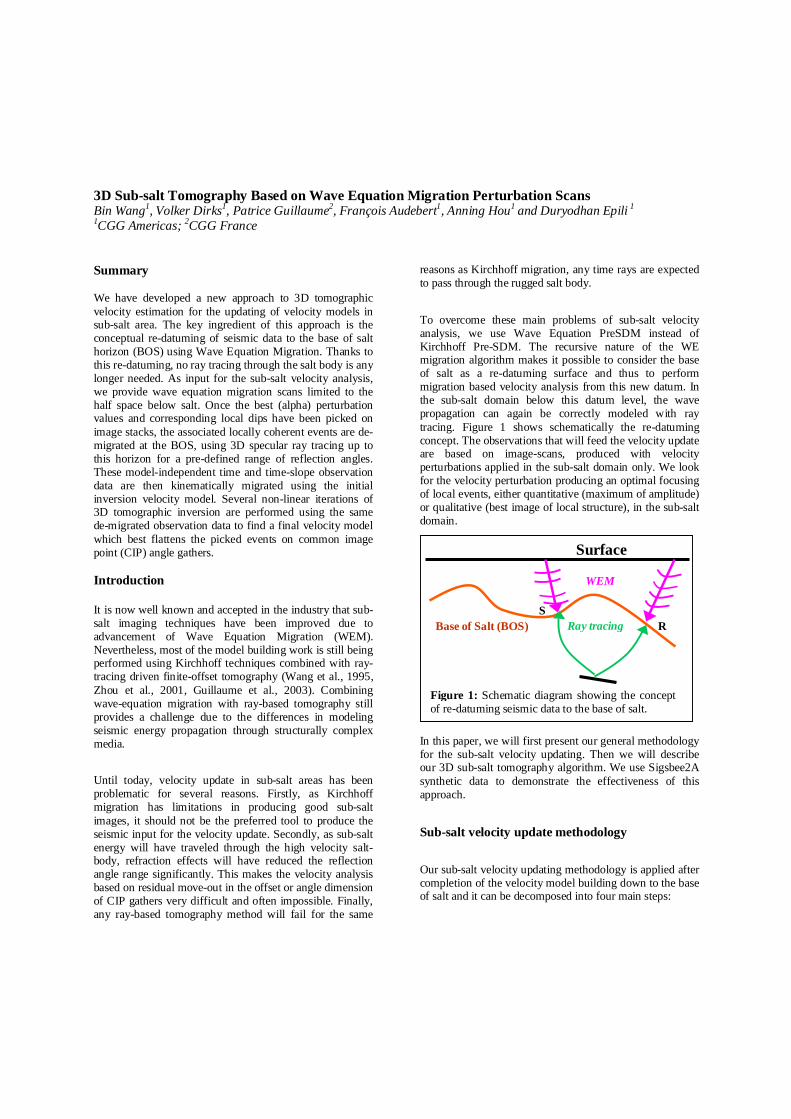
To overcome these main problems of sub-salt velocity analysis, we use Wave Equation PreSDM instead of Kirchhoff Pre-SDM. The recursive nature of the WE migration algorithm makes it possible to consider the base of salt as a re-datuming surface and thus to perform migration based velocity analysis from this new datum. In the sub-salt domain below this datum level, the wave propagation can again be correctly modeled with ray tracing. Figure 1 shows schematically the re-datuming concept. The observations that will feed the velocity update are based on image-scans, produced with velocity perturbations applied in the sub-salt domain only. We look for the velocity perturbation producing an optimal focusing of local events, either quantitative (maximum of amplitude) or qualitative (best image of local structure), in the sub-salt domain.
In this paper, we will first present our general methodology for the sub-salt velocity updating. Then we will describe our 3D sub-salt tomography algorithm. We use Sigsbee2A synthetic data to demonstrate the effectiveness of this approach.
Sub-salt velocity update methodology
Our sub-salt velocity updating methodology is applied after completion of the velocity model building down to the base of salt and it can be decomposed into four main steps:
Surface
S R
WEM
Base of Salt (BOS) Ray tracing
Figure 1: Schematic diagram showing the concept of re-datuming seismic data to the base of salt.
3D Sub-salt Tomography
1. Creating a set of depth migration stack cubes using wave-equation migration: renditions of the initial velocity model are created by perturbing the initial velocity field below a base of salt (BOS) datum horizon using α scaling factors (Audebert et al., 1996). Then Wave-equation PreSDM will produce migrated images for each of these renditions, below the BOS datum.
2. Picking the best-imaged events in depth domain: The scan approach allows using several picking criteria (maximum energy, resolution, spatial coherency) for defining the best focusing. The following information is extracted for each of the picked local reflectors: the x,y,z position, the α perturbation value, and the local dip. For a better legibility and an easier picking, the migrated depth images are converted to a pseudo-depth scale: they are first converted to time, each using its own migration velocity model, next, they are converted back to a pseudo depth scale using a common velocity model.
3. De-migration of the picked data: As the velocities used by the migrations scan have been perturbed only below the BOS datum we are able to de-migrate our alpha-picks to this same datum. This has a big advantage: in the smooth sub-salt domain, there is no significant mismatch between the seismic wave propagation as simulated by the wave-equation Pre-SDM and the ray-tracing used by the 3D finite-angle tomography.
4. Model update: Once the depth/perturbation picks have been de-migrated from the scaled depth migrated domain to the un-(migrated time domain an improved velocity model can be estimated either by 3D tomography or by simple 1D update.
3D Sub-salt velocity model update using finite-angle tomography in the depth domain
The key ingredient of our 3D sub-salt tomography is the conceptual re-datuming of seismic data at a base of salt (BOS) datum horizon using wave equation migration. Thanks to this re-datuming, there is no requirement for ray-tracing through the salt bodies. Since this BOS datum becomes the actual “surface” for the 3D tomography in sub-salt area, we have adjusted our routinely used 3D tomography (Guillaume et al., 2003), so that it will recognize this new “surface”datum:
1. The (virtual) sources and receivers are now located on the BOS datum horizon.
2. For the kinematical de-migration of an event in a CIP, the 3D specular rays stop at the BOS datum, and since at this datum level the local “offset” is not known, the pair of rays have to be shot according to the local specular angle at the local event.
3. The kinematical migration is performed from the BOS datum. As in the original implementation of our tomography, this kinematical re-migration allows multiple non-linear iterations without having to re-migrate the whole seismic data.
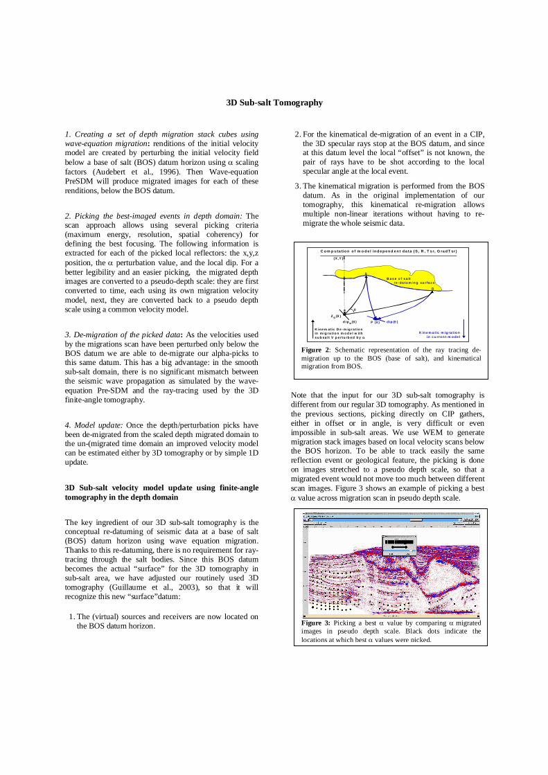
Note that the input for our 3D sub-salt tomography is different from our regular 3D tomography. As mentioned in the previous sections, picking directly on CIP gathers, either in offset or in angle, is very difficult or even impossible in sub-salt areas. We use WEM to generate migration stack images based on local velocity scans below the BOS horizon. To be able to track easily the same reflection event or geological feature, the picking is done on images stretched to a pseudo depth scale, so that a migrated event would not move too much between different scan images. Figure 3 shows an example of picking a best α value across migration scan in pseudo depth scale.
Z α (θ )
(X ,Y )
S
R
d ip α ( θ ) P ( θ )
θ
B a s e o f s a lt re -da tu m in g su r fa c e
C o m p u ta tio n o f m o d e l in d e p e n d e n t d a t a ( S , R , T s r, G ra d T sr )
d ip (θ )
K in e m a t ic m ig ra t io n in c u rr e n t m o de l
in m ig r a tio n m o d e l w ithK ine m at ic D e -m ig r a tio n
s u b sa l t V p e rtu rb e d b y α
Figure 2: Schematic representation of the ray tracing de-migration up to the BOS (base of salt), and kinematical migration from BOS.
Figure 3: Picking a best α value by comparing α migrated images in pseudo depth scale. Black dots indicate thelocations at which best α values were picked.
3D Sub-salt Tomography
Synthetic data example
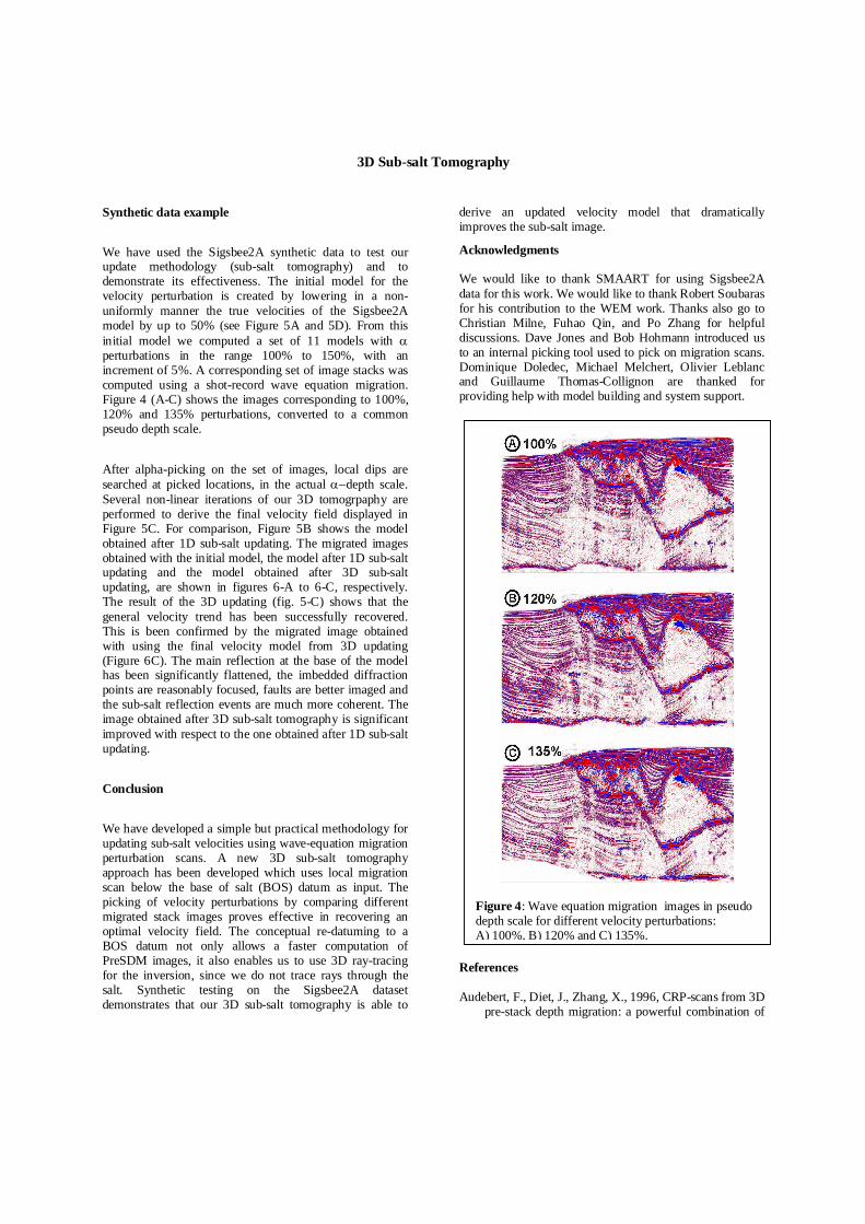
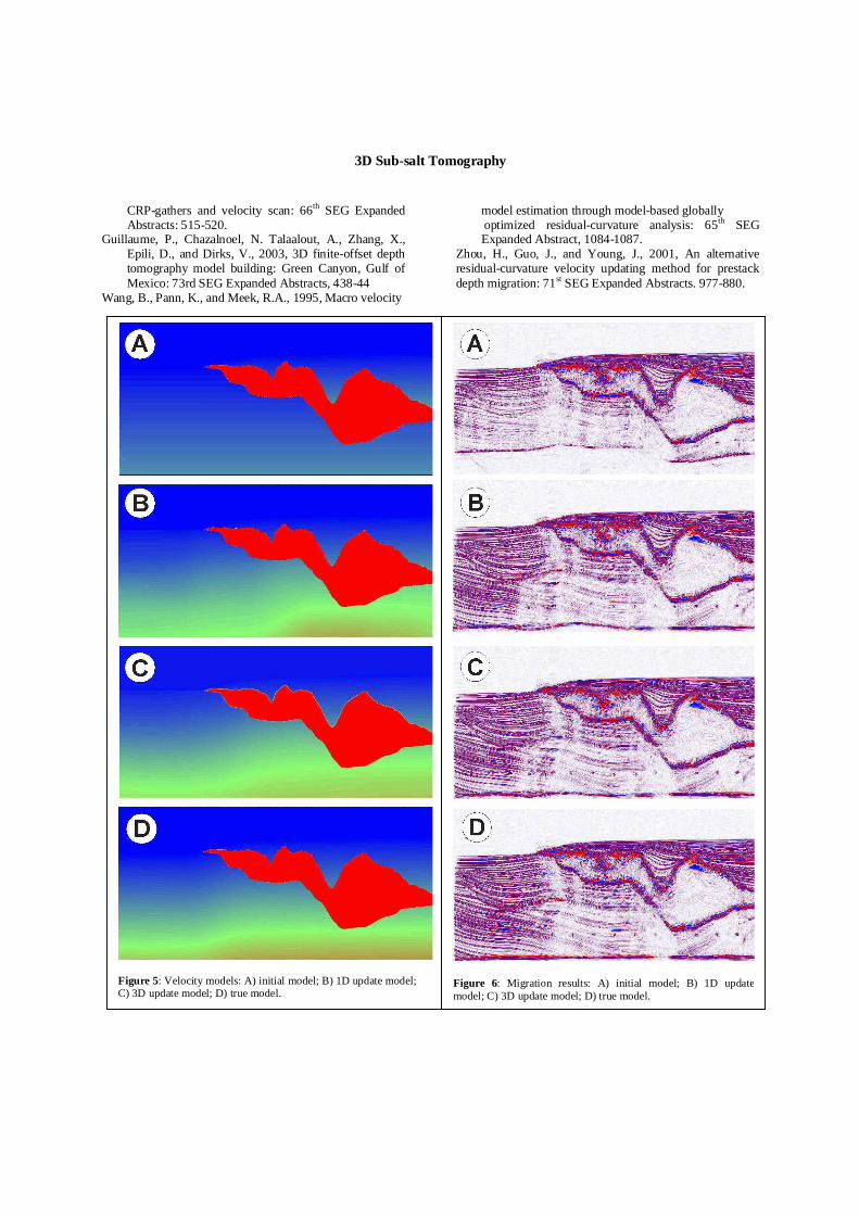
We have used the Sigsbee2A synthetic data to test our update methodology (sub-salt tomography) and to demonstrate its effectiveness. The initial model for the velocity perturbation is created by lowering in a non-uniformly manner the true velocities of the Sigsbee2A model by up to 50% (see Figure 5A and 5D). From this initial model we computed a set of 11 models with α perturbations in the range 100% to 150%, with an increment of 5%. A corresponding set of image stacks was computed using a shot-record wave equation migration. Figure 4 (A-C) shows the images corresponding to 100%, 120% and 135% perturbations, converted to a common pseudo depth scale.
After alpha-picking on the set of images, local dips are searched at picked locations, in the actual α−depth scale. Several non-linear iterations of our 3D tomogrpaphy are performed to derive the final velocity field displayed in Figure 5C. For comparison, Figure 5B shows the model obtained after 1D sub-salt updating. The migrated images obtained with the initial model, the model after 1D sub-salt updating and the model obtained after 3D sub-salt updating, are shown in figures 6-A to 6-C, respectively. The result of the 3D updating (fig. 5-C) shows that the general velocity trend has been successfully recovered. This is been confirmed by the migrated image obtained with using the final velocity model from 3D updating (Figure 6C). The main reflection at the base of the model has been significantly flattened, the imbedded diffraction points are reasonably focused, faults are better imaged and the sub-salt reflection events are much more coherent. The image obtained after 3D sub-salt tomography is significant improved with respect to the one obtained after 1D sub-salt updating.
Conclusion
We have developed a simple but practical methodology for updating sub-salt velocities using wave-equation migration perturbation scans. A new 3D sub-salt tomography approach has been developed which uses local migration scan below the base of salt (BOS) datum as input. The picking of velocity perturbations by comparing different migrated stack images proves effective in recovering an optimal velocity field. The conceptual re-datuming to a BOS datum not only allows a faster computation of PreSDM images, it also enables us to use 3D ray-tracing for the inversion, since we do not trace rays through the salt. Synthetic testing on the Sigsbee2A dataset demonstrates that our 3D sub-salt tomography is able to
derive an updated velocity model that dramatically improves the sub-salt image.
Acknowledgments We would like to thank SMAART for using Sigsbee2A data for this work. We would like to thank Robert Soubaras for his contribution to the WEM work. Thanks also go to Christian Milne, Fuhao Qin, and Po Zhang for helpful discussions. Dave Jones and Bob Hohmann introduced us to an internal picking tool used to pick on migration scans. Dominique Doledec, Michael Melchert, Olivier Leblanc and Guillaume Thomas-Collignon are thanked for providing help with model building and system support.
References Audebert, F., Diet, J., Zhang, X., 1996, CRP-scans from 3D
pre-stack depth migration: a powerful combination of
Figure 4: Wave equation migration images in pseudo depth scale for different velocity perturbations: A) 100%, B) 120% and C) 135%.
3D Sub-salt Tomography
CRP-gathers and velocity scan: 66th SEG Expanded Abstracts: 515-520.
Guillaume, P., Chazalnoel, N. Talaalout, A., Zhang, X., Epili, D., and Dirks, V., 2003, 3D finite-offset depth tomography model building: Green Canyon, Gulf of Mexico: 73rd SEG Expanded Abstracts, 438-44
Wang, B., Pann, K., and Meek, R.A., 1995, Macro velocity
model estimation through model-based globally optimized residual-curvature analysis: 65th SEG Expanded Abstract, 1084-1087.
Zhou, H., Guo, J., and Young, J., 2001, An alternative residual-curvature velocity updating method for prestack depth migration: 71st SEG Expanded Abstracts. 977-880.
Figure 5: Velocity models: A) initial model; B) 1D update model; C) 3D update model; D) true model.
Figure 6: Migration results: A) initial model; B) 1D update model; C) 3D update model; D) true model.