Embed Size (px)
Citation preview
3GPP TS 23.203 V10.6.0 (2012-03) Technical Specification
3rd Generation Partnership Project;Technical Specification Group Services and System Aspects;
Policy and charging control architecture(Release 10)
The present document has been developed within the 3rd Generation Partnership Project (3GPP TM) and may be further elaborated for the purposes of 3GPP. The present document has not been subject to any approval process by the 3GPP Organizational Partners and shall not be implemented. This Specification is provided for future development work within 3GPP only. The Organizational Partners accept no liability for any use of this Specification. Specifications and reports for implementation of the 3GPP TM system should be obtained via the 3GPP Organizational Partners' Publications Offices.
3GPP
3GPP TS 23.203 V10.6.0 (2012-03) 2Release 10
Keywords LTE, UMTS, GSM, Charging, Performance
3GPP
Postal address
3GPP support office address 650 Route des Lucioles - Sophia Antipolis
Valbonne - FRANCE Tel.: +33 4 92 94 42 00 Fax: +33 4 93 65 47 16
Internet http://www.3gpp.org
Copyright Notification
No part may be reproduced except as authorized by written permission. The copyright and the foregoing restriction extend to reproduction in all media.
© 2012, 3GPP Organizational Partners (ARIB, ATIS, CCSA, ETSI, TTA, TTC).
All rights reserved.
UMTS™ is a Trade Mark of ETSI registered for the benefit of its members 3GPP™ is a Trade Mark of ETSI registered for the benefit of its Members and of the 3GPP Organizational Partners LTE™ is a Trade Mark of ETSI currently being registered for the benefit of its Members and of the 3GPP Organizational Partners GSM® and the GSM logo are registered and owned by the GSM Association
3GPP
3GPP TS 23.203 V10.6.0 (2012-03) 3Release 10
Contents Foreword ...................................................................................................................................................... 9 Introduction .................................................................................................................................................. 9 1 Scope ................................................................................................................................................ 10 2 References ........................................................................................................................................ 10 3 Definitions, symbols and abbreviations ............................................................................................. 11 3.1 Definitions ................................................................................................................................................. 11 3.2 Abbreviations............................................................................................................................................. 13 4 High level requirements .................................................................................................................... 14 4.1 General requirements ................................................................................................................................. 14 4.2 Charging related requirements .................................................................................................................... 14 4.2.1 General ................................................................................................................................................. 14 4.2.2 Charging models ................................................................................................................................... 15 4.2.2a Charging requirements .......................................................................................................................... 15 4.2.3 Examples of Service Data Flow Charging ............................................................................................. 16 4.3 Policy control requirements ........................................................................................................................ 16 4.3.1 General ................................................................................................................................................. 16 4.3.2 Gating control ....................................................................................................................................... 17 4.3.3 QoS control .......................................................................................................................................... 17 4.3.3.1 QoS control at service data flow level .............................................................................................. 17 4.3.3.2 QoS control at IP-CAN bearer level ................................................................................................. 17 4.3.3.3 QoS Conflict Handling .................................................................................................................... 17 4.4 Usage Monitoring Control .......................................................................................................................... 18 5 Architecture model and reference points............................................................................................ 18 5.1 Reference architecture ................................................................................................................................ 18 5.2 Reference points ........................................................................................................................................ 21 5.2.1 Rx reference point ................................................................................................................................ 21 5.2.2 Gx reference point ................................................................................................................................ 22 5.2.3 Reference points to subscriber databases ............................................................................................... 22 5.2.3.1 Sp reference point............................................................................................................................ 22 5.2.3.2 Ud reference point ........................................................................................................................... 22 5.2.4 Gy reference point ................................................................................................................................ 22 5.2.5 Gz reference point ................................................................................................................................ 23 5.2.6 S9 reference point ................................................................................................................................. 23 5.2.7 Gxx reference point .............................................................................................................................. 23 6 Functional description ....................................................................................................................... 24 6.1 Overall description ..................................................................................................................................... 24 6.1.0 General ................................................................................................................................................. 24 6.1.1 Binding mechanism .............................................................................................................................. 24 6.1.1.1 General ........................................................................................................................................... 24 6.1.1.2 Session binding ............................................................................................................................... 24 6.1.1.3 PCC rule authorization and QoS rule generation .............................................................................. 25 6.1.1.4 Bearer Binding ................................................................................................................................ 26 6.1.2 Reporting ............................................................................................................................................. 27 6.1.3 Credit management ............................................................................................................................... 27 6.1.4 Event Triggers ...................................................................................................................................... 28 6.1.5 Policy Control ...................................................................................................................................... 30 6.1.6 Service (data flow) Prioritization and Conflict Handling ........................................................................ 31 6.1.7 Standardized QoS characteristics........................................................................................................... 31 6.1.7.1 General ........................................................................................................................................... 31 6.1.7.2 Standardized QCI characteristics ..................................................................................................... 32 6.1.7.3 Allocation and Retention Priority characteristics .............................................................................. 34 6.1.8 Termination Action ............................................................................................................................... 35 6.1.9 Handling of packet filters provided to the UE by PCEF/BBERF ............................................................ 35
3GPP
3GPP TS 23.203 V10.6.0 (2012-03) 4Release 10
6.1.10 IMS Emergency Session Support .......................................................................................................... 36 6.1.10.1 Architecture model and Reference points ......................................................................................... 36 6.1.10.2 PCC Rule Authorization and QoS rule generation ............................................................................ 36 6.1.10.3 Functional Entities........................................................................................................................... 36 6.1.10.3.1 PCRF ......................................................................................................................................... 36 6.1.10.3.2 PCEF ......................................................................................................................................... 37 6.1.10.3.3 P-CSCF ..................................................................................................................................... 37 6.1.10.4 PCC Procedures and Flows .............................................................................................................. 37 6.1.11 Multimedia Priority Service Support ..................................................................................................... 37 6.1.11.1 Architecture model and Reference points ......................................................................................... 37 6.1.11.2 PCC rule authorization and QoS rule generation .............................................................................. 37 6.1.11.3 Priority EPS Bearer Service ............................................................................................................. 38 6.1.11.4 Bearer priority for IMS Multimedia Priority Services ....................................................................... 38 6.2 Functional entities ...................................................................................................................................... 38 6.2.1 Policy Control and Charging Rules Function (PCRF) ............................................................................ 38 6.2.1.0 General ........................................................................................................................................... 38 6.2.1.1 Input for PCC decisions ................................................................................................................... 42 6.2.1.2 Subscription information management in the PCRF ......................................................................... 43 6.2.1.3 V-PCRF .......................................................................................................................................... 44 6.2.1.3.1 General ...................................................................................................................................... 44 6.2.1.3.2 V-PCRF and Home Routed Access ............................................................................................ 44 6.2.1.3.3 V-PCRF and Visited Access (local breakout) .............................................................................. 44 6.2.1.4 H-PCRF .......................................................................................................................................... 45 6.2.1.4.1 General ...................................................................................................................................... 45 6.2.1.4.2 H-PCRF and Home Routed Access ............................................................................................ 46 6.2.1.4.3 H-PCRF and Visited Access (Local Breakout) ............................................................................ 46 6.2.1.5 Handling of Multiple BBFs associated with the same IP-CAN session.............................................. 46 6.2.1.5.1 Handling of two BBFs associated with the same IP-CAN session during handover ...................... 46 6.2.1.5.2 Handling of multiple BBFs with IP-CAN session flow mobility .................................................. 47 6.2.2 Policy and Charging Enforcement Function (PCEF) .............................................................................. 48 6.2.2.1 General ........................................................................................................................................... 48 6.2.2.2 Service data flow detection .............................................................................................................. 50 6.2.2.3 Measurement ................................................................................................................................... 53 6.2.2.4 QoS control ..................................................................................................................................... 54 6.2.3 Application Function (AF) .................................................................................................................... 54 6.2.4 Subscription Profile Repository (SPR) .................................................................................................. 55 6.2.5 Online Charging System ....................................................................................................................... 56 6.2.6 Offline Charging System (OFCS) .......................................................................................................... 56 6.2.7 Bearer Binding and Event Reporting Function (BBERF) ....................................................................... 56 6.2.7.1 General ........................................................................................................................................... 56 6.2.7.2 Service data flow detection .............................................................................................................. 56 6.2.7.3 QoS Control .................................................................................................................................... 57 6.2.8 User Data Repository (UDR) ................................................................................................................ 57 6.3 Policy and charging control rule ................................................................................................................. 57 6.3.1 General ................................................................................................................................................. 57 6.3.2 Policy and charging control rule operations ........................................................................................... 62 6.4 IP-CAN bearer and IP-CAN session related policy information................................................................... 63 6.5 Quality of Service Control rule ................................................................................................................... 64 6.5.1 General ................................................................................................................................................. 64 6.5.2 Quality of Service control rule operations .............................................................................................. 65 6.6 Usage Monitoring Control specific information .......................................................................................... 66 6.6.1 General ................................................................................................................................................. 66 6.6.2 Usage Monitoring Control operations .................................................................................................... 66 6.7 IP flow mobility Routing rule ..................................................................................................................... 66 6.7.1 General ................................................................................................................................................. 66 6.7.2 Routing rule operations ......................................................................................................................... 67 7 PCC Procedures and flows ................................................................................................................ 67 7.1 Introduction ............................................................................................................................................... 67 7.2 IP-CAN Session Establishment .................................................................................................................. 69 7.3 IP-CAN Session Termination ..................................................................................................................... 71 7.3.1 UE initiated IP-CAN Session termination .............................................................................................. 71
3GPP
3GPP TS 23.203 V10.6.0 (2012-03) 5Release 10
7.3.2 GW(PCEF) initiated IP-CAN Session termination ................................................................................. 73 7.4 IP-CAN Session Modification .................................................................................................................... 74 7.4.1 IP-CAN Session Modification; GW(PCEF) initiated.............................................................................. 74 7.4.2 IP-CAN Session Modification; PCRF initiated ...................................................................................... 77 7.4.3 Void ..................................................................................................................................................... 79 7.5 Update of the subscription information in the PCRF ................................................................................... 80 7.6 PCRF Discovery and Selection ................................................................................................................... 80 7.6.1 General principles ................................................................................................................................. 80 7.6.2 Solution Principles ................................................................................................................................ 81 7.7 Gateway Control Session Procedures .......................................................................................................... 82 7.7.1 Gateway Control Session Establishment ................................................................................................ 82 7.7.1.0 General ........................................................................................................................................... 82 7.7.1.1 Gateway Control Session Establishment during Attach .................................................................... 83 7.7.1.2 Gateway Control Session Establishment during BBERF Relocation ................................................. 84 7.7.2 Gateway Control Session Termination .................................................................................................. 86 7.7.2.1 GW(BBERF)-Initiated Gateway Control Session Termination ......................................................... 86 7.7.2.2 PCRF-Initiated Gateway Control Session Termination ..................................................................... 87 7.7.3 Gateway Control and QoS Rules Request .............................................................................................. 87 7.7.3.1 General ........................................................................................................................................... 87 7.7.3.2 Event reporting for PCEF in visited network and locally terminated Gxx interaction ........................ 89 7.7.4 Gateway Control and QoS Rules Provision............................................................................................ 90 7.7.5 Void ..................................................................................................................................................... 91 7.8 Change in subscription for MPS priority services ........................................................................................ 91
Annex A (normative): Access specific aspects (3GPP) ................................................................... 92 A.1 GPRS ............................................................................................................................................... 92 A.1.0 General ...................................................................................................................................................... 92 A.1.1 High level requirements ............................................................................................................................. 92 A.1.1.1 General ................................................................................................................................................. 92 A.1.1.2 Charging related requirements............................................................................................................... 92 A.1.1.3 Policy control requirements................................................................................................................... 92 A.1.1.4 QoS control .......................................................................................................................................... 93 A.1.2 Architecture model and reference points ..................................................................................................... 93 A.1.2.1 Reference points ................................................................................................................................... 93 A.1.2.1.1 Gx reference point ........................................................................................................................... 93 A.1.2.2 Reference architecture .......................................................................................................................... 93 A.1.3 Functional description ................................................................................................................................ 93 A.1.3.1 Overall description................................................................................................................................ 93 A.1.3.1.1 Binding mechanism ......................................................................................................................... 93 A.1.3.1.1.0 General ...................................................................................................................................... 93 A.1.3.1.1.1 Bearer binding mechanism allocated to the PCEF ....................................................................... 94 A.1.3.1.1.2 Bearer binding mechanism allocated to the PCRF ....................................................................... 94 A.1.3.1.2 Reporting ........................................................................................................................................ 95 A.1.3.1.3 Credit management.......................................................................................................................... 95 A.1.3.1.4 Event Triggers ................................................................................................................................. 95 A.1.3.1.5 Policy Control ................................................................................................................................. 96 A.1.3.2 Functional entities................................................................................................................................. 96 A.1.3.2.1 Policy Control and Charging Rules Function (PCRF) ....................................................................... 96 A.1.3.2.1.0 General ...................................................................................................................................... 96 A.1.3.2.1.1 Input for PCC decisions ............................................................................................................. 96 A.1.3.2.2 Policy and Charging Enforcement Function (PCEF) ......................................................................... 97 A.1.3.2.2.1 General ...................................................................................................................................... 97 A.1.3.2.2.2 Service data flow detection......................................................................................................... 98 A.1.3.2.2.3 Packet Routeing and Transfer Function ...................................................................................... 98 A.1.3.2.2.4 Measurement ............................................................................................................................. 98 A.1.3.2.3 Application Function (AF) ............................................................................................................... 99 A.1.3.3 Policy and charging control rule ............................................................................................................ 99 A.1.3.3.1 General ........................................................................................................................................... 99 A.1.3.3.2 Policy and charging control rule operations ...................................................................................... 99 A.1.3.4 IP-CAN bearer and IP-CAN session related policy information ............................................................. 99 A.1.3.5 APN related policy information........................................................................................................... 100
3GPP
3GPP TS 23.203 V10.6.0 (2012-03) 6Release 10
A.1.4 PCC Procedures and flows ....................................................................................................................... 100 A.1.4.1 Introduction ........................................................................................................................................ 100 A.1.4.2 IP-CAN Session Establishment ........................................................................................................... 100 A.1.4.3 IP-CAN Session Termination .............................................................................................................. 100 A.1.4.3.1 UE initiated IP-CAN Session termination ...................................................................................... 100 A.1.4.3.2 GW initiated IP-CAN Session termination ..................................................................................... 100 A.1.4.4 IP-CAN Session Modification ............................................................................................................. 101 A.1.4.4.1 IP-CAN Session Modification; GW(PCEF) initiated ...................................................................... 101 A.1.4.4.2 IP-CAN Session Modification; PCRF initiated ............................................................................... 101 A.2 Void ............................................................................................................................................... 102 A.3 Void ............................................................................................................................................... 102 A.4 3GPP Accesses (GERAN/UTRAN/E-UTRAN) - GTP-based EPC .................................................. 102 A.4.0 General .................................................................................................................................................... 102 A.4.1 High Level Requirements ......................................................................................................................... 102 A.4.1.1 Charging related requirements............................................................................................................. 102 A.4.1.2 QoS control ........................................................................................................................................ 102 A.4.2 Architectural Model and Reference Points ................................................................................................ 103 A.4.2.1 Reference architecture ........................................................................................................................ 103 A.4.3 Functional Description ............................................................................................................................. 103 A.4.3.1 Overall description.............................................................................................................................. 103 A.4.3.1.1 Credit management........................................................................................................................ 103 A.4.3.1.2 Event Triggers ............................................................................................................................... 104 A.4.3.1.3 Binding mechanism ....................................................................................................................... 104 A.4.3.1.4 Policy Control ............................................................................................................................... 105 A.4.3.2 Functional Entities .............................................................................................................................. 105 A.4.3.2.1 Policy Control and Charging Rules Function (PCRF) ..................................................................... 105 A.4.3.2.2 Policy and Charging Enforcement Function (PCEF) ....................................................................... 105 A.4.3.2.3 Application Function (AF) ............................................................................................................. 106 A.4.3.3 APN related policy information........................................................................................................... 106 A.4.3.4 IP-CAN bearer and IP-CAN session related policy information ........................................................... 106 A.4.4 PCC Procedures and Flows ...................................................................................................................... 107 A.4.4.1 Introduction ........................................................................................................................................ 107 A.4.4.2 IP-CAN Session Establishment ........................................................................................................... 107 A.4.4.3 GW(PCEF) initiated IP-CAN Session termination ............................................................................... 107 A.4.4.4 IP-CAN Session Modification ............................................................................................................. 107 A.4.4.4.1 IP-CAN Session Modification; GW(PCEF) initiated ...................................................................... 107 A.4.4.4.2 IP-CAN Session Modification; PCRF initiated ............................................................................... 108 A.5 3GPP Accesses (GERAN/UTRAN/E-UTRAN) - PMIP-based EPC ................................................ 108 A.5.0 General .................................................................................................................................................... 108 A.5.1 High Level Requirements ......................................................................................................................... 108 A.5.1.0 General ............................................................................................................................................... 108 A.5.1.1 QoS control ........................................................................................................................................ 108 A.5.2 Architectural Model and Reference Points ................................................................................................ 108 A.5.2.1 Reference architecture ........................................................................................................................ 108 A.5.3 Functional Description ............................................................................................................................. 109 A.5.3.1 Overall Description ............................................................................................................................. 109 A.5.3.1.1 Binding mechanism ....................................................................................................................... 109 A.5.3.1.2 Credit management........................................................................................................................ 109 A.5.3.1.3 Event triggers ................................................................................................................................ 109 A.5.3.2 Functional Entities .............................................................................................................................. 109 A.5.3.2.1 Policy Control and Charging Rules Function (PCRF) ..................................................................... 109 A.5.3.2.2 Policy and Charging Enforcement Function (PCEF) ....................................................................... 109 A.5.3.2.3 Bearer Binding and Event Reporting Function (BBERF) ................................................................ 109 A.5.3.3 Void ................................................................................................................................................... 110 A.5.3.4 APN related policy information........................................................................................................... 110 A.5.3.5 IP-CAN bearer and IP-CAN session related policy information ........................................................... 110 A.5.4 PCC Procedures and Flows ...................................................................................................................... 110 A.5.4.1 Introduction ........................................................................................................................................ 110 A.5.4.2 Gateway Control Session Establishment .............................................................................................. 110
3GPP
3GPP TS 23.203 V10.6.0 (2012-03) 7Release 10
A.5.4.3 Gateway Control and QoS Rules Request ............................................................................................ 110 A.5.4.4 Gateway Control and QoS Rules Provisioning ..................................................................................... 111 A.5.4.5 IP-CAN Session Establishment ........................................................................................................... 111 A.5.4.6 IP-CAN Session Modification ............................................................................................................. 111 A.5.4.6.1 IP-CAN Session Modification; GW(PCEF) initiated ...................................................................... 111 A.5.4.6.2 IP-CAN Session Modification; PCRF initiated ............................................................................... 111 A.5.4.6.3 Void .............................................................................................................................................. 111
Annex B (informative): Void .......................................................................................................... 112
Annex C (informative): Void .......................................................................................................... 113
Annex D (informative): Access specific aspects (Non-3GPP)......................................................... 114 D.1 DOCSIS IP-CAN ............................................................................................................................ 114 D.1.1 General .................................................................................................................................................... 114 D.1.1 High level requirements ........................................................................................................................... 114 D.1.1.1 General ............................................................................................................................................... 114 D.1.1.2 Charging related requirements............................................................................................................. 115 D.1.1.3 Policy control requirements................................................................................................................. 115 D.1.2 Architecture model and reference points ................................................................................................... 116 D.1.2.1 Reference points ................................................................................................................................. 116 D.1.2.1.1 Rx reference point ......................................................................................................................... 116 D.1.2.1.2 Gx reference point ......................................................................................................................... 116 D.1.2.1.3 Void .............................................................................................................................................. 116 D.1.3 Functional description .............................................................................................................................. 116 D.1.3.1 Overall description.............................................................................................................................. 116 D.1.3.1.1 Binding mechanism ....................................................................................................................... 116 D.1.3.2 Functional entities............................................................................................................................... 117 D.1.3.2.1 Policy Control and Charging Rules Function (PCRF) ..................................................................... 117 D.1.3.2.1.1 Input for PCC decisions ........................................................................................................... 117 D.1.3.2.2 Policy and Charging Enforcement Function (PCEF) ....................................................................... 117 D.1.3.2.3 Application Function (AF) ............................................................................................................. 117 D.1.3.3 Policy and charging control rule .......................................................................................................... 117 D.1.3.3.1 General ......................................................................................................................................... 117 D.1.3.3.2 Policy and charging control rule operations .................................................................................... 117 D.2 WiMAX IP-CAN ............................................................................................................................ 118 D.2.1 High level requirements ........................................................................................................................... 118 D.2.1.1 General ............................................................................................................................................... 118 D.2.1.2 Charging related requirements............................................................................................................. 118 D.2.1.3 Policy control requirements................................................................................................................. 118 D.2.2 Architecture model and reference points ................................................................................................... 119 D.2.2.1 Reference points ................................................................................................................................. 119 D.2.2.1.1 Rx reference point ......................................................................................................................... 119 D.2.2.1.2 Gx reference point ......................................................................................................................... 119 D.2.2.1.3 Sp reference point.......................................................................................................................... 119 D.2.3 Functional description .............................................................................................................................. 119 D.2.3.1 Overall description.............................................................................................................................. 119 D.2.3.1.1 Binding mechanism ....................................................................................................................... 119 D.2.3.1.2 Credit management........................................................................................................................ 119 D.2.3.1.3 Event triggers ................................................................................................................................ 119 D.2.3.2 Functional entities............................................................................................................................... 119 D.2.3.2.1 Policy Control and Charging Rules Function (PCRF) ..................................................................... 119 D.2.3.2.2 Policy and Charging Enforcement Function (PCEF) ....................................................................... 120 D.2.3.2.3 Application Function (AF) ............................................................................................................. 120 D.2.3.3 Policy and charging control rule .......................................................................................................... 120 D.2.3.3.1 General ......................................................................................................................................... 120 D.2.3.3.1 Policy and charging control rule operations .................................................................................... 120
3GPP
3GPP TS 23.203 V10.6.0 (2012-03) 8Release 10
Annex E (informative): Void .......................................................................................................... 121
Annex F (informative): Void .......................................................................................................... 122
Annex G (informative): PCC rule precedence configuration......................................................... 123
Annex H (normative): Access specific aspects (EPC-based Non-3GPP) ..................................... 124 H.1 General ........................................................................................................................................... 124 H.2 EPC-based cdma2000 HRPD Access .............................................................................................. 124
Annex I (informative): Void .......................................................................................................... 125
Annex J (informative): Standardized QCI characteristics - rationale and principles ................. 126
Annex K (informative): Limited PCC Deployment ........................................................................ 127
Annex L (normative): Limited PCC Deployment ........................................................................ 127
Annex M (informative): Handling of UE or network responsibility for the resource management of services ........................................................................... 128
Annex N (informative): PCC usage for sponsored data connectivity ............................................ 129 N.1 General ........................................................................................................................................... 129 N.2 Reporting for sponsored data connectivity ....................................................................................... 130
Annex O (informative): Change history ......................................................................................... 131
3GPP
3GPP TS 23.203 V10.6.0 (2012-03) 9Release 10
Foreword This Technical Specification has been produced by the 3rd Generation Partnership Project (3GPP).
The contents of the present document are subject to continuing work within the TSG and may change following formal TSG approval. Should the TSG modify the contents of the present document, it will be re-released by the TSG with an identifying change of release date and an increase in version number as follows:
Version x.y.z
where:
x the first digit:
1 presented to TSG for information;
2 presented to TSG for approval;
3 or greater indicates TSG approved document under change control.
y the second digit is incremented for all changes of substance, i.e. technical enhancements, corrections, updates, etc.
z the third digit is incremented when editorial only changes have been incorporated in the document.
Introduction Policy and Charging Control functionality encompasses two main functions:
- Flow Based Charging, including charging control and online credit control;
- Policy control (e.g. gating control, QoS control, QoS signalling, etc.).
The present document specifies the generic PCC aspects within the body, while the specifics for each type of IP-CAN are specified in Annexes. For one type of IP-CAN the corresponding clause in an Annex shall be understood to be a realization of the TS main body. The Annexes are therefore not stand-alone specifications for an IP-CAN. Annexes may specify additional restrictions to the specification body.
3GPP
3GPP TS 23.203 V10.6.0 (2012-03) 10Release 10
1 Scope The present document specifies the overall stage 2 level functionality for Policy and Charging Control that encompasses the following high level functions for IP-CANs (e.g. GPRS, I-WLAN, Fixed Broadband, etc.):
- Flow Based Charging, including charging control and online credit control;
- Policy control (e.g. gating control, QoS control, QoS signalling, etc.).
The present document specifies the Policy and Charging Control functionality for Evolved 3GPP Packet Switched domain, including both 3GPP accesses (GERAN/UTRAN/E-UTRAN) and Non-3GPP accesses, according to TS 23.401 [17] and TS 23.402 [18].
The present document specifies functionality for unicast bearers. Broadcast and multicast bearers, such as MBMS contexts for GPRS, are out of scope for the present release of this document.
2 References The following documents contain provisions which, through reference in this text, constitute provisions of the present document.
References are either specific (identified by date of publication, edition number, version number, etc.) or non-specific.
For a specific reference, subsequent revisions do not apply.
For a non-specific reference, the latest version applies. In the case of a reference to a 3GPP document (including a GSM document), a non-specific reference implicitly refers to the latest version of that document in the same Release as the present document.
[1] 3GPP TS 41.101: "Technical Specifications and Technical Reports for a GERAN-based 3GPP system".
[2] Void.
[3] 3GPP TS 32.240: "Telecommunication management; Charging management; Charging architecture and principles".
[4] IETF RFC 4006: "Diameter Credit-Control Application".
[5] 3GPP TS 23.207: "End-to-end Quality of Service (QoS) concept and architecture".
[6] 3GPP TS 23.246: "Multimedia Broadcast/Multicast Service (MBMS); Architecture and functional description".
[7] 3GPP TS 23.125: "Overall high level functionality and architecture impacts of flow based charging; Stage 2".
[8] 3GPP TR 21.905: "Vocabulary for 3GPP Specifications".
[9] 3GPP TS 32.251: "Telecommunication management; Charging management; Packet Switched (PS) domain charging".
[10] 3GPP TS 29.061: "Interworking between the Public Land Mobile Network (PLMN) supporting packet based services and Packet Data Networks (PDN)".
[11] 3GPP TR 33.919: "3G Security; Generic Authentication Architecture (GAA); System description".
[12] 3GPP TS 23.060: "General Packet Radio Service (GPRS); Service description; Stage 2".
[13] 3GPP TS 23.234: "3GPP system to Wireless Local Area Network (WLAN) interworking; System description".
3GPP
3GPP TS 23.203 V10.6.0 (2012-03) 11Release 10
[14] 3GPP TS 23.107: "Quality of Service (QoS) concept and architecture".
[15] "WiMAX End-to-End Network Systems Architecture" (http://www.wimaxforum.org/technology/documents).
[16] 3GPP TS 23.003: "Numbering, addressing and identification".
[17] 3GPP TS 23.401: "General Packet Radio Service (GPRS) enhancements for Evolved Universal Terrestrial Radio Access Network (E-UTRAN) access".
[18] 3GPP TS 23.402: "Architecture Enhancements for non-3GPP accesses".
[19] 3GPP TS 36.300: "Evolved Universal Terrestrial Radio Access (E-UTRA) and Evolved Universal Terrestrial Radio Access Network (E-UTRAN); Overall description; Stage 2".
[20] 3GPP2 X.P0057-0 v0.6.0: "E UTRAN - HRPD Connectivity and Interworking: Core Network Aspects", work in progress.
[21] 3GPP TS 23.167: "IP Multimedia Subsystem (IMS) emergency sessions".
[22] 3GPP TS 29.213: "Policy and Charging Control signalling flows and QoS parameter mapping".
[23] 3GPP TS 23.261: "IP Flow Mobility and seamless WLAN offload; Stage 2".
[24] 3GPP TS 23.198: "Open Service Access (OSA); Stage 2".
[25] 3GPP TS 23.335: "User Data Convergence (UDC); Technical realization and information flows; Stage 2".
[26] 3GPP TS 29.335: "User Data Convergence (UDC); User Data Repository Access Protocol over the Ud interface; Stage 3".
[27] 3GPP TS 23.216: "Single Radio Voice Call Continuity (SRVCC); Stage 2".
3 Definitions, symbols and abbreviations
3.1 Definitions For the purposes of the present document, the terms and definitions given in TR 21.905 [8] and the following apply. A term defined in the present document takes precedence over the definition of the same term, if any, in TR 21.905 [8].
application service provider: A business entity responsible for the application that is being / will be used by a UE, which may be either an AF operator or has an association with the AF operator.
authorised QoS: The maximum QoS that is authorised for a service data flow. In case of an aggregation of multiple service data flows within one IP-CAN bearer (e.g. for GPRS a PDP context), the combination of the "Authorised QoS" information of the individual service data flows is the "Authorised QoS" for the IP-CAN bearer. It contains the QoS class identifier and the data rate.
binding: The association between a service data flow and the IP-CAN bearer (for GPRS the PDP context) transporting that service data flow.
binding mechanism: The method for creating, modifying and deleting bindings.
charging control: The process of associating packets, belonging to a service data flow, to a charging key and applying online charging and/or offline charging, as appropriate.
charging key: information used by the online and offline charging system for rating purposes.
dynamic PCC Rule: a PCC rule for which the definition is provided into the PCEF via the Gx reference point.
3GPP
3GPP TS 23.203 V10.6.0 (2012-03) 12Release 10
event report: a notification, possibly containing additional information, of an event which occurs that corresponds with an event trigger. Also, an event report is a report from the PCRF to the AF concerning transmission resources or requesting additional information.
event trigger: a rule specifying the event reporting behaviour of a PCEF or BBERF. Also, a trigger for credit management events.
gating control: The process of blocking or allowing packets, belonging to a service data flow, to pass through to the desired endpoint.
Gateway Control Session: An association between a BBERF and a PCRF (when GTP is not used in the EPC), used for transferring access specific parameters, BBERF events and QoS rules between PCRF and BBERF.
GBR bearer: An IP-CAN bearer with reserved (guaranteed) bitrate resources.
GPRS IP-CAN: This IP-CAN incorporates GPRS over GERAN and UTRAN, see TS 23.060 [12].
IP-CAN bearer: An IP transmission path of defined capacity, delay and bit error rate, etc. See TR 21.905 [8] for the definition of bearer.
IP-CAN session: The association between a UE and an IP network. The association is identified by one IPv4 and/or an IPv6 prefix together with UE identity information, if available, and a PDN represented by a PDN ID (e.g. an APN). An IP-CAN session incorporates one or more IP-CAN bearers. Support for multiple IP-CAN bearers per IP-CAN session is IP-CAN specific. An IP-CAN session exists as long as UE IP addresses/prefix are established and announced to the IP network.
I-WLAN IP-CAN: This IP-CAN incorporates 3GPP IP access of I-WLAN, see TS 23.234 [13].
non-GBR bearer: An IP-CAN bearer with no reserved (guaranteed) bitrate resources.
operator-controlled service: A service for which complete PCC rule information, including service data flow filter information, is available in the PCRF through configuration and/or dynamic interaction with an AF.
packet flow: A specific user data flow carried through the PCEF. A packet flow can be an IP flow.
PCC decision: A decision consists of PCC rules and IP-CAN bearer attributes, which is provided by the PCRF to the PCEF for policy and charging control.
PCC rule: A set of information enabling the detection of a service data flow and providing parameters for policy control and/or charging control.
policy control: The process whereby the PCRF indicates to the PCEF how to control the IP-CAN bearer. Policy control includes QoS control and/or gating control.
pre-defined PCC Rule: a PCC rule that has been provisioned directly into the PCEF by the operator.
QoS class identifier (QCI): A scalar that is used as a reference to a specific packet forwarding behaviour (e.g. packet loss rate, packet delay budget) to be provided to a SDF. This may be implemented in the access network by the QCI referencing node specific parameters that control packet forwarding treatment (e.g. scheduling weights, admission thresholds, queue management thresholds, link layer protocol configuration, etc.), that have been pre-configured by the operator at a specific node(s) (e.g. eNodeB).
QoS rule: A set of information enabling the detection of a service data flow and defining its associated QoS parameters.
Monitoring key: information used by the PCEF and PCRF for usage monitoring control purposes as a reference to a given set of service data flows that all share a common allowed usage on a per UE and APN basis.
service data flow: An aggregate set of packet flows that matches a service data flow template.
service data flow filter: A set of packet flow header parameter values/ranges used to identify one or more of the packet flows constituting a service data flow. The possible service data flow filters are defined in clause 6.2.2.2.
service data flow filter identifier: A scalar that is unique for a specific service data flow (SDF) filter (used on Gx and Gxx)within an IP-CAN session.
3GPP
3GPP TS 23.203 V10.6.0 (2012-03) 13Release 10
service data flow template: The set of service data flow filters in a PCC rule, required for defining a service data flow.
service identifier: An identifier for a service. The service identifier provides the most detailed identification, specified for flow based charging, of a service data flow. A concrete instance of a service may be identified if additional AF information is available (further details to be found in clause 6.3.1).
session based service: An end user service requiring application level signalling, which is separated from service rendering.
subscribed guaranteed bandwidth QoS: The per subscriber, authorized cumulative guaranteed bandwidth QoS which is provided by the SPR/UDR to the PCRF.
subscriber category: is a means to group the subscribers into different classes, e.g. gold user, the silver user and the bronze user.
uplink bearer binding verification: The network enforcement of terminal compliance with the negotiated uplink traffic mapping to bearers.
3.2 Abbreviations For the purposes of the present document, the abbreviations given in TR 21.905 [8] and the following apply. An abbreviation defined in the present document takes precedence over the definition of the same abbreviation, if any, in TR 21.905 [8].
AF Application Function BBERF Bearer Binding and Event Reporting Function BBF Bearer Binding Function CSG Closed Subscriber Group CSG ID Closed Subscriber Group Identity DRA Diameter Routing Agent H-PCEF A PCEF in the HPLMN H-PCRF A PCRF in the HPLMN HRPD High Rate Packet Data HSGW HRPD Serving Gateway IP-CAN IP Connectivity Access Network MPS Multimedia Priority Service OFCS Offline Charging System OCS Online Charging System PCC Policy and Charging Control PCEF Policy and Charging Enforcement Function PCRF Policy and Charging Rules Function QCI QoS Class Identifier SPR Subscription Profile Repository UDC User Data Convergence UDR User Data Repository V-PCEF A PCEF in the VPLMN V-PCRF A PCRF in the VPLMN
3GPP
3GPP TS 23.203 V10.6.0 (2012-03) 14Release 10
4 High level requirements
4.1 General requirements It shall be possible for the PCC architecture to base decisions upon subscription information.
It shall be possible to apply policy and charging control to any kind of 3GPP IP-CAN and any non-3GPP accesses connected via EPC complying with TS 23.402 [18]. Applicability of PCC to other IP-CANs is not restricted. However, it shall be possible for the PCC architecture to base decisions upon the type of IP-CAN used (e.g. GPRS, I-WLAN, etc.).
The policy and charging control shall be possible in the roaming and local breakout scenarios defined in TS 23.401 [17] and TS 23.402 [18].
The PCC architecture shall discard packets that don't match any service data flow filter of the active PCC rules. It shall also be possible for the operator to define PCC rules, with wild-carded service data flow filters, to allow for the passage and charging for packets that do not match any service data flow filter of any other active PCC rules.
The PCC architecture shall allow the charging control to be applied on a per service data flow basis, independent of the policy control.
The PCC architecture shall have a binding method that allows the unique association between service data flows and their IP-CAN bearer.
A single service data flow template shall suffice, to detect a service data flow, for the purpose of both policy control and flow based charging.
A PCC rule may be predefined or dynamically provisioned at establishment and during the lifetime of an IP-CAN session. The latter is referred to as a dynamic PCC rule.
The number of real-time PCC interactions shall be minimized although not significantly increasing the overall system reaction time. This requires optimized interfaces between the PCC nodes.
It shall be possible to take a PCC rule into service, and out of service, at a specific time of day, without any PCC interaction at that point in time.
PCC shall be enabled on a per PDN basis (represented by an access point and the configured range of IP addresses) at the PCEF. It shall be possible for the operator to configure the PCC architecture to perform charging control, policy control or both for a PDN access.
PCC shall support roaming users.
The PCC architecture shall allow the resolution of conflicts which would otherwise cause a subscriber’s Subscribed Guaranteed Bandwidth QoS to be exceeded.
The PCC architecture shall support topology hiding.
It should be possible to use PCC architecture for handling IMS-based emergency service.
It shall be possible with the PCC architecture, in real-time, to monitor the overall amount of resources that are consumed by a user and to control usage independently from charging mechanisms, the so-called usage monitoring control.
4.2 Charging related requirements
4.2.1 General In order to allow for charging control, the information in the PCC rule identifies the service data flow and specifies the parameters for charging control. The PCC rule information may depend on subscription data.
3GPP
3GPP TS 23.203 V10.6.0 (2012-03) 15Release 10
For the purpose of charging correlation between application level (e.g. IMS) and service data flow level, applicable charging identifiers shall be passed along within the PCC architecture, if such identifiers are available.
For the purpose of charging correlation between service data flow level and application level (e.g. IMS) as well as on-line charging support at the application level, applicable charging identifiers and IP-CAN type identifiers shall be passed from the PCRF to the AF, if such identifiers are available.
4.2.2 Charging models The PCC charging shall support the following charging models:
- Volume based charging;
- Time based charging;
- Volume and time based charging;
- Event based charging;
- No charging.
NOTE 1: The charging model - "No charging" implies that charging control is not applicable.
Shared revenue services shall be supported. In this case settlement for all parties shall be supported, including the third parties that may have been involved providing the services.
NOTE 2: When developing a charging solution, the PCC charging models may be combined to form the solution. How to achieve a specific solution is however not within the scope of this TS.
4.2.2a Charging requirements It shall be possible to apply different rates and charging models when a user is identified to be roaming from when the user is in the home network. Furthermore, it shall be possible to apply different rates and charging models based on the location of a user, beyond the granularity of roaming.
It shall be possible to apply different rates and charging models when a user consuming network services via a CSG cell or a hybrid cell according to the user CSG information. User CSG information includes CSG ID, access mode and CSG membership indication.
It shall be possible to apply a separate rate to a specific service, e.g. allow the user to download a certain volume of data, reserved for the purpose of one service for free, and then continue with a rate causing a charge.
It shall be possible to change the rate based on the time of day.
It shall be possible to enforce per-service usage limits for a service data flow using online charging on a per user basis (may apply to prepaid and post-paid users).
It shall be possible for the online charging system to set and send the thresholds (time and/or volume based) for the amount of remaining credit to the PCEF for monitoring. In case the PCEF detects that any of the time based or volume based credit falls below the threshold, the PCEF shall send a request for credit re-authorization to the OCS with the remaining credit (time and/or volume based).
It shall be possible for the charging system to select the applicable rate based on:
- home/visited IP-CAN;
- User CSG information;
- IP-CAN bearer characteristics (e.g. QoS);
- QoS provided for the service;
- time of day;
- IP-CAN specific parameters according to Annex A.
3GPP
3GPP TS 23.203 V10.6.0 (2012-03) 16Release 10
The charging system maintains the tariff information, determining the rate based on the above input. Thus the rate may change e.g. as a result of IP-CAN session modification to change the bearer characteristics provided for a service data flow.
The charging rate or charging model applicable to a service data flow may change as a result of events in the service (e.g. insertion of a paid advertisement within a user requested media stream).
The charging model applicable to a service data flow may change as a result of events identified by the OCS (e.g. after having spent a certain amount of time and/or volume, the user gets to use some services for free).
The charging rate or charging model applicable to a service data flow may change as a result of having used the service data flow for a certain amount of time and/or volume.
In the case of online charging, it shall be possible to apply an online charging action upon PCEF events (e.g. re-authorization upon QoS change).
It shall be possible to indicate to the PCEF that interactions with the charging systems are not required for a PCC rule, i.e. to perform neither accounting nor credit control for this service data flow, and then no offline charging information is generated.
4.2.3 Examples of Service Data Flow Charging There are many different services that may be used within a network, including both user-user and user-network services. Service data flows from these services may be identified and charged in many different ways. A number of examples of configuring PCC rules for different service data flows are described below.
EXAMPLE 1: A network server provides an FTP service. The FTP server supports both the active (separate ports for control and data) and passive modes of operation. A PCC rule is configured for the service data flows associated with the FTP server for the user. The PCC rule uses a filter specification for the uplink that identifies packets sent to port 20 or 21 of the IP address of the server, and the origination information is wildcarded. In the downlink direction, the filter specification identifies packets sent from port 20 or 21 of the IP address of the server.
EXAMPLE 2: A network server provides a "web" service. A PCC rule is configured for the service data flows associated with the HTTP server for the user. The PCC rule uses a filter specification for the uplink that identifies packets sent to port 80 of the IP address of the server, and the origination information is wildcarded. In the downlink direction, the filter specification identifies packets sent from port 80 of the IP address of the server.
EXAMPLE 3: The same server provides a WAP service. The server has multiple IP addresses, and the IP address of the WAP server is different from the IP address of the web server. The PCC rule uses the same filter specification as for the web server, but with the IP addresses for the WAP server only.
EXAMPLE 4: An operator offers a zero rating for network provided DNS service. A PCC rule is established setting all DNS traffic to/from the operators DNS servers as offline charged. The data flow filter identifies the DNS port number, and the source/destination address within the subnet range allocated to the operators network nodes.
EXAMPLE 5: An operator has a specific charging rate for user-user VoIP traffic over the IMS. A PCC rule is established for this service data flow. The filter information to identify the specific service data flow for the user-user traffic is provided by the P-CSCF (AF).
EXAMPLE 6: An operator is implementing UICC based authentication mechanisms for HTTP based services utilizing the GAA Framework as defined in TR 33.919 [11] by e.g. using the Authentication Proxy. The Authentication Proxy may appear as an AF and provide information to the PCRF for the purpose of selecting an appropriate PCC Rule.
4.3 Policy control requirements
4.3.1 General The policy control features comprise gating control and QoS control.
3GPP
3GPP TS 23.203 V10.6.0 (2012-03) 17Release 10
The concept of QoS class identifier and the associated bitrates specify the QoS information for service data flows and bearers on the Gx and Gxx reference points.
4.3.2 Gating control Gating control shall be applied by the PCEF on a per service data flow basis.
To enable the PCRF gating control decisions, the AF shall report session events (e.g. session termination, modification) to the PCRF. For example, session termination, in gating control, may trigger the blocking of packets or "closing the gate".
4.3.3 QoS control
4.3.3.1 QoS control at service data flow level
It shall be possible to apply QoS control on a per service data flow basis in the PCEF.
QoS control per service data flow allows the PCC architecture to provide the PCEF with the authorized QoS to be enforced for each specific service data flow. Criteria such as the QoS subscription information may be used together with policy rules such as, service-based, subscription-based, or pre-defined PCRF internal policies to derive the authorized QoS to be enforced for a service data flow.
It shall be possible to apply multiple PCC rules, without application provided information, using different authorised QoS within a single IP-CAN session and within the limits of the Subscribed QoS profile.
4.3.3.2 QoS control at IP-CAN bearer level
It shall be possible for the PCC architecture to support control of QoS reservation procedures (UE-initiated or network-initiated) for IP-CANs that support such procedures for its IP-CAN bearers in the PCEF or the BBERF, if applicable. It shall be possible to determine the QoS to be applied in QoS reservation procedures (QoS control) based on the authorised QoS of the service data flows that are applicable to the IP-CAN bearer and on criteria such as the QoS subscription information, service based policies, and/or pre-defined PCRF internal policies. Details of QoS reservation procedures are IP-CAN specific and therefore, the control of these procedures is described in Annex A and Annex D.
It shall be possible for the PCC architecture to support control of QoS for the packet traffic of IP-CANs.
The PCC architecture shall be able to provide policy control in the presence of NAT devices. This may be accomplished by providing appropriate address and port information to the PCRF.
The enforcement of the control for QoS reservation procedures for an IP-CAN bearer shall allow for a downgrading or an upgrading of the requested QoS as part of a UE-initiated IP-CAN bearer establishment and modification. The PCC architecture shall be able to provide a mechanism to initiate IP-CAN bearer establishment and modification (for IP-CANs that support such procedures for its bearers) as part of the QoS control.
The IP-CAN shall prevent cyclic QoS upgrade attempts due to failed QoS upgrades.
NOTE: These measures are IP-CAN specific.
The PCC architecture shall be able to handle IP-CAN bearers that require a guaranteed bitrate (GBR bearers) and IP-CAN bearers for which there is no guaranteed bitrate (non-GBR bearers).
4.3.3.3 QoS Conflict Handling
It shall be possible for the PCC architecture to support conflict resolution in the PCRF when the authorized bandwidth associated with multiple PCC rules exceeds the Subscribed Guaranteed bandwidth QoS.
3GPP
3GPP TS 23.203 V10.6.0 (2012-03) 18Release 10
4.4 Usage Monitoring Control It shall be possible to apply usage monitoring for the accumulated usage of network resources on a per IP-CAN session and user basis. This capability is required for enforcing dynamic policy decisions based on the total network usage in real-time.
The PCRF that use usage monitoring for making dynamic policy decisions shall set and send the applicable thresholds to the PCEF for monitoring. The usage monitoring thresholds shall be based on volume. The PCEF shall notify the PCRF when a threshold is reached and report the accumulated usage since the last report for usage monitoring.
The usage monitoring capability shall be possible to apply for an individual service data flow, a group of services data flows, or for all traffic of an IP-CAN session. Usage monitoring shall be activated both for service data flows associated with predefined PCC rules and dynamic PCC rules, including rules with deferred activation and/or deactivation times while those rules are active.
5 Architecture model and reference points
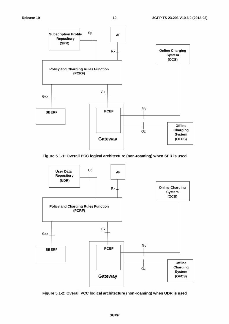
5.1 Reference architecture The PCC functionality is comprised by the functions of the Policy and Charging Enforcement Function, the Bearer Binding and Event Reporting Function (BBERF), the Policy and Charging Rules Function, the Application Function, the Online Charging System, the Offline Charging System and the Subscription Profile Repository or the User Data Repository. UDR replaces SPR when the UDC architecture as defined in TS 23.335 [25] is applied to store PCC related subscription data. In this deployment scenario Ud interface between PCRF and UDR is used to access subscription data in the UDR.
NOTE 1: When UDC architecture is used, SPR and Sp, whenever mentioned in this document, can be replaced by UDR and Ud.
The PCC architecture extends the architecture of an IP-CAN, where the Policy and Charging Enforcement Function is a functional entity in the Gateway node implementing the IP access to the PDN. The allocation of the Bearer Binding and Event Reporting Function is specific to each IP-CAN type and specified in the corresponding Annex.
The non-3GPP network relation to the PLMN is the same as defined in TS 23.402 [18].
3GPP
3GPP TS 23.203 V10.6.0 (2012-03) 19Release 10
Gy
Gz
Subscription Profile Repository
(SPR)
Rx
AFSp
Gx
Offline Charging System (OFCS)Gateway
PCEF
Policy and Charging Rules Function (PCRF)
Gxx
BBERF
Online ChargingSystem (OCS)
Figure 5.1-1: Overall PCC logical architecture (non-roaming) when SPR is used
Gy
Gz
User Data Repository
(UDR)
Rx
AFUd
Gx
Offline Charging System (OFCS)Gateway
PCEF
Policy and Charging Rules Function (PCRF)
Gxx
BBERF
Online Charging System (OCS)
Figure 5.1-2: Overall PCC logical architecture (non-roaming) when UDR is used
3GPP
3GPP TS 23.203 V10.6.0 (2012-03) 20Release 10
Gy
Gz
Subscription Profile
Repository(SPR)
Rx
AF Sp
Gx
Offline ChargingSystem(OFCS) Gateway
PCEF
Policy and Charging Rules Function (H-PCRF)
Gxx
BBERF
Policy and Charging Rules Function (V-PCRF)
S9VPLMN
HPLMN Online Charging
System (OCS)
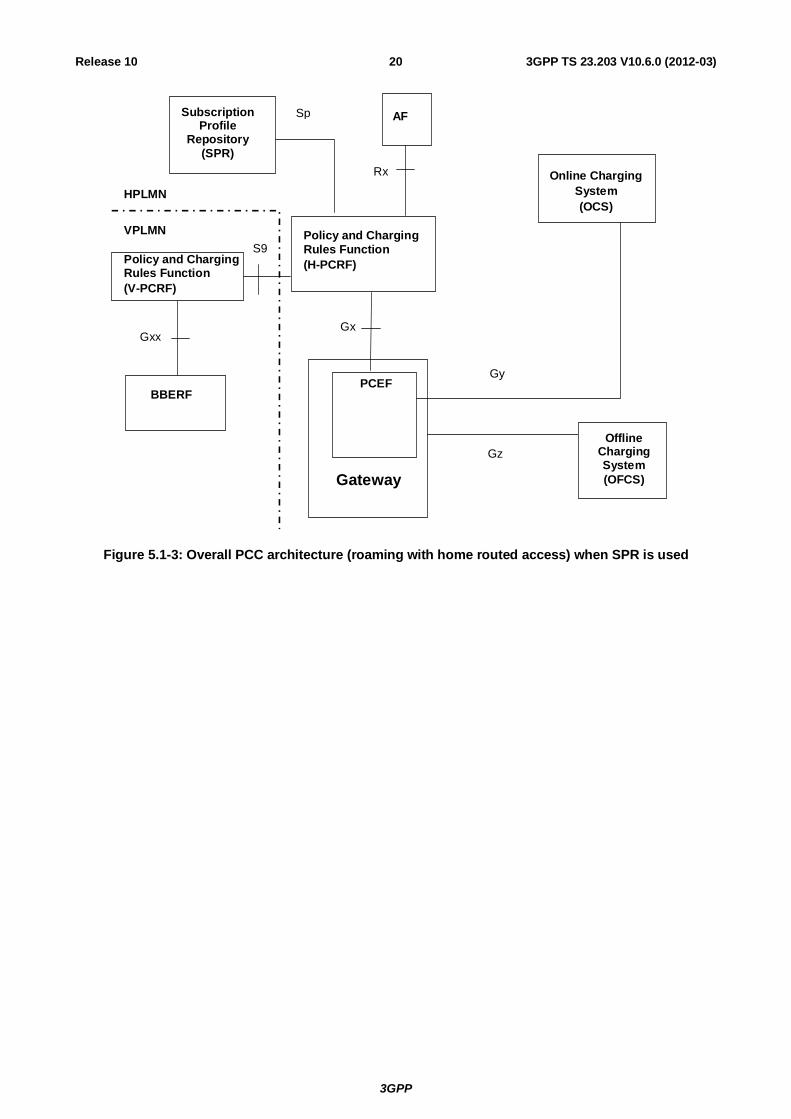
Figure 5.1-3: Overall PCC architecture (roaming with home routed access) when SPR is used
3GPP
3GPP TS 23.203 V10.6.0 (2012-03) 21Release 10
AF
Rx
RepositorySubscription Profile
(SPR)
Sp
VPLMN HPLMN
S9
Policy and Charging Rules Function (V-PCRF)
Policy and Charging Rules Function (H- PCRF)
Rx
AF
Gx Gxx
PCEF
Gateway
Gy
Gz
Offline Charging System (OFCS)
BBERF
Online Charging System (OCS)
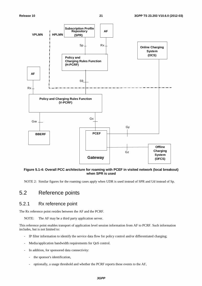
Figure 5.1-4: Overall PCC architecture for roaming with PCEF in visited network (local breakout) when SPR is used
NOTE 2: Similar figures for the roaming cases apply when UDR is used instead of SPR and Ud instead of Sp.
5.2 Reference points
5.2.1 Rx reference point The Rx reference point resides between the AF and the PCRF.
NOTE: The AF may be a third party application server.
This reference point enables transport of application level session information from AF to PCRF. Such information includes, but is not limited to:
- IP filter information to identify the service data flow for policy control and/or differentiated charging;
- Media/application bandwidth requirements for QoS control.
- In addition, for sponsored data connectivity:
- the sponsor's identification,
- optionally, a usage threshold and whether the PCRF reports these events to the AF,
3GPP
3GPP TS 23.203 V10.6.0 (2012-03) 22Release 10
- information identifying the application service provider and application (e.g. SDFs, Application ID, etc.).
The Rx reference point enables the AF subscription to notifications on IP-CAN bearer level events (e.g. signalling path status of AF session) in the IP-CAN.
5.2.2 Gx reference point The Gx reference point resides between the PCEF and the PCRF.
The Gx reference point enables a PCRF to have dynamic control over the PCC behaviour at a PCEF.
The Gx reference point enables the signalling of PCC decision, which governs the PCC behaviour, and it supports the following functions:
- Request for PCC decision from PCEF to PCRF;
- Provision of IP flow mobility routing information from PCEF to PCRF; this applies only when IP flow mobility as defined in TS 23.261 [23] is supported;
- Provision of PCC decision from PCRF to PCEF;
- Delivery of IP-CAN-specific parameters from PCRF to PCEF or from PCEF to PCRF; this applies only when Gxx is deployed.
- Negotiation of IP-CAN bearer establishment mode (UE-only or UE/NW);
- Termination of Gx session (corresponding to an IP-CAN session) by PCEF or PCRF.
NOTE: The PCRF decision to termination an Gx session is based on operator policies. It should only occur in rare situations (e.g. the removal of a UE subscription) to avoid service interruption due to the termination of the IP-CAN session.
A PCC decision consists of zero or more PCC rule(s) and IP-CAN attributes. The information contained in a PCC rule is defined in clause 6.3.
5.2.3 Reference points to subscriber databases
5.2.3.1 Sp reference point
The Sp reference point lies between the SPR and the PCRF.
The Sp reference point allows the PCRF to request subscription information related to the IP-CAN transport level policies from the SPR based on a subscriber ID, a PDN identifier and possible further IP-CAN session attributes, see Annex A and Annex D. For example, the subscriber ID can be IMSI. The reference point allows the SPR to notify the PCRF when the subscription information has been changed if the PCRF has requested such notifications. The SPR shall stop sending the updated subscription information when a cancellation notification request has been received from the PCRF.
NOTE: The details associated with the Sp reference point are not specified in this Release.
5.2.3.2 Ud reference point
The Ud reference point resides between the UDR and the PCRF, acting as an Application Frontend as defined in TS 23.335 [25]. It is used by the PCRF to access PCC related subscription data when stored in the UDR.
The details for this reference point are described in TS 23.335 [25] and TS 29.335 [26].
5.2.4 Gy reference point The Gy reference point resides between the OCS and the PCEF.
The Gy reference point allows online credit control for service data flow based charging. The functionalities required across the Gy reference point are defined in TS 32.251 [9] and is based on RFC 4006 [4].
3GPP
3GPP TS 23.203 V10.6.0 (2012-03) 23Release 10
For a visited access, the VPLMN may use an OCS proxy between the PCEF and the OCS.
5.2.5 Gz reference point The Gz reference point resides between the PCEF and the OFCS.
The Gz reference point enables transport of service data flow based offline charging information.
The Gz interface is specified in TS 32.240 [3].
5.2.6 S9 reference point The S9 reference point resides between a PCRF in the HPLMN (H-PCRF) and a PCRF in the VPLMN (V-PCRF).
For roaming with a visited access (PCEF and, if applicable, BBERF in the visited network), the S9 reference point enables the H-PCRF to (via the V-PCRF):
- have dynamic PCC control, including both the PCEF and, if applicable, BBERF, in the VPLMN;
- deliver or receive IP-CAN-specific parameters from both the PCEF and, if applicable, BBERF, in the VPLMN;
- serve Rx authorizations and event subscriptions from an AF in the VPLMN.
For roaming with a home routed access, the S9 enables the H-PCRF to provide dynamic QoS control policies from the HPLMN, via a V-PCRF, to a BBERF in the VPLMN.
5.2.7 Gxx reference point The Gxx reference point resides between the PCRF and the BBERF. This reference point corresponds to the Gxa and Gxc, as defined in TS 23.402 [18] and further detailed in the annexes.
The Gxx reference point enables a PCRF to have dynamic control over the BBERF behaviour.
The Gxx reference point enables the signalling of QoS control decisions and it supports the following functions:
- Establishment of Gxx session by BBERF;
Termination of Gxx session by BBERF or PCRF;
- Establishment of Gateway Control Session by the BBERF;
- Termination of Gateway Control Session by the BBERF or PCRF;
- Request for QoS decision from BBERF to PCRF;
- Provision of QoS decision from PCRF to BBERF;
- Delivery of IP-CAN-specific parameters from PCRF to BBERF or from BBERF to PCRF;
- Negotiation of IP-CAN bearer establishment mode (UE-only and UE/NW).
A QoS control decision consists of zero or more QoS rule(s) and IP-CAN attributes. The information contained in a QoS rule is defined in clause 6.5.
NOTE: The Gxx session serves as a channel for communication between the BBERF and the PCRF. A Gateway Control Session utilizes the Gxx session and operates as defined in TS 23.402 [18], which includes both the alternatives as defined by cases 2a and 2b in clause 7.1.
3GPP
3GPP TS 23.203 V10.6.0 (2012-03) 24Release 10
6 Functional description
6.1 Overall description
6.1.0 General The PCC architecture works on a service data flow level. The PCC architecture provides the functions for policy and charging control as well as event reporting for service data flows.
6.1.1 Binding mechanism
6.1.1.1 General
The binding mechanism is the procedure that associates a service data flow (defined in a PCC and QoS rule, if applicable, by means of the SDF template), to the IP-CAN bearer deemed to transport the service data flow. For service data flows belonging to AF sessions, the binding mechanism shall also associate the AF session information with the IP-CAN bearer that is selected to carry the service data flow.
NOTE 1: The relation between AF sessions and rules depends only on the operator configuration. An AF session can be covered by one or more PCC and QoS rules, if applicable (e.g. one rule per media component of an IMS session). Alternatively, a rule could comprise multiple AF sessions.
NOTE 2: The PCRF may authorize dynamic PCC rules for service data flows without a corresponding AF session. Such PCC rules may be statically configured at the PCRF or dynamically filled with the UE provided traffic mapping information.
The binding mechanism creates bindings. The algorithm, employed by the binding mechanism, may contain elements specific for the kind of IP-CAN.
The binding mechanism includes three steps:
1. Session binding.
2 PCC rule authorization and QoS rule generation, if applicable.
3. Bearer binding.
6.1.1.2 Session binding
Session binding is the association of the AF session information to an IP-CAN session.
The PCRF shall perform the session binding, which shall take the following IP-CAN parameters into account:
a) The UE IPv4 address and/or IPv6 network prefix;
b) The UE identity (of the same kind), if present.
NOTE 1: In case the UE identity in the IP-CAN and the application level identity for the user are of different kinds, the PCRF needs to maintain, or have access to, the mapping between the identities. Such mapping is not subject to specification within this TS.
c) The information about the packet data network (PDN) the user is accessing, if present.
NOTE 2: Only a 1:1 mapping between the Rx session and IP-CAN session is supported in this Release.
The PCRF shall identify the PCC rules affected by the AF session information, including new rules to be installed and existing rules to be modified or removed.
3GPP
3GPP TS 23.203 V10.6.0 (2012-03) 25Release 10
6.1.1.3 PCC rule authorization and QoS rule generation
PCC Rule authorization is the selection of the QoS parameters (QCI, ARP, GBR, MBR, etc.) for the PCC rules.
The PCRF shall perform the PCC rule authorization for complete dynamic PCC rules belonging to AF sessions that have been selected in step 1, as described in clause 6.1.1.2, as well as for PCC rules without corresponding AF sessions. Based on AF instructions (as described in clause 6.1.5) dynamic PCC rules can be authorized even if they are not complete (e.g. due to missing service information regarding QoS or traffic filter parameters).
The PCC rule authorization depends on the IP-CAN bearer establishment mode of the IP-CAN session and the mode (UE or NW) of the PCC rule:
- In UE/NW bearer establishment mode, the PCRF shall perform the authorization for all PCC rules that are to be handled in NW mode.
- Otherwise, if PCC rules are to be handled in UE mode or when in UE-only bearer establishment mode, the PCRF shall first identify the PCC rules that correspond to a UE resource request and authorize only these.
The PCRF shall compare the traffic mapping information of the UE resource request with the service data flow filter information of the services that are allowed for the user. Each part of the traffic mapping information shall be evaluated separately in the order of their related precedence. Any matching service data flow filter leads to an authorization of the corresponding PCC rule for the UE resource request unless the PCC rule is already authorized for a more specific traffic mapping information or the PCC rule cannot be authorized for the QCI that is related to the UE resource request (the details are described in the next paragraph). Since a PCC rule can contain multiple service data flow filters it shall be ensured by the PCRF that a service data flow is only authorized for a single UE resource request.
NOTE 3: For example, a PCC rule containing multiple service data flow filters that match traffic mapping information of different UE resource requests could be segmented by the PCRF according to the different matching traffic mapping information. Afterwards, the PCRF can authorize the different PCC rules individually.
The PCRF knows whether a PCC rule can be authorized for a single QCI only or a set of QCIs (based on SPR information or local configuration). If the processing of the traffic mapping information would lead to an authorization of a PCC rule, the PCRF shall also check whether the PCC rule can be authorized for the QCI that is related to the UE resource request containing the traffic mapping information. If the PCC rule cannot be authorized for this QCI, the PCRF shall reject the traffic mapping information unless otherwise stated in an access-specific Annex.
If there is any traffic mapping information not matching to any service data flow filter known to the PCRF and the UE is allowed to request for enhanced QoS for traffic not belonging to operator-controlled services, the PCRF shall authorize this traffic mapping information by adding the respective service data flow filter to a new or existing PCC. If the PCRF received an SDF filter identifier together with this traffic mapping information, the PCRF shall modify the existing PCC rule if the PCC rule is authorized for a GBR QCI.
NOTE 4: If the PCC rule is authorized for a non-GBR QCI, the PCRF may either create a new PCC rule or modify the existing PCC rule.
The PCC rule that needs to be modified can be identified by the service data flow filter the SDF filter identifier refers to. The requested QoS shall be checked against the subscription limitations for traffic not belonging to operator-controlled services.
If the PCRF needs to perform the authorization based on incomplete service information and thus cannot associate a PCC rule with a single IP-CAN bearer, then the PCRF shall generate for the affected service data flow an individual PCC rule per IP-CAN bearer that could carry that service data flow. Once the PCRF receives the complete service information, the PCC rule on the IP-CAN bearer with the matching traffic mapping information shall be updated according to the service information. Any other PCC rule(s) previously generated for the same service data flow shall be removed by the PCRF.
NOTE 5: This is required to enable the successful activation or modification of IP-CAN bearers before knowing the intended use of the IP-CAN bearers to carry the service data flow(s).
For an IP-CAN, where the PCRF gains no information about the uplink IP flows (i.e. the UE provided traffic mapping information contains no information about the uplink IP flows), the binding mechanism shall assume that, for bi-directional service data flows, both downlink and uplink packets travel on the same IP-CAN bearer.
3GPP
3GPP TS 23.203 V10.6.0 (2012-03) 26Release 10
Whenever the service data flow template or the UE provided traffic mapping information change, the existing authorizations shall be re-evaluated, i.e. the authorization procedure specified in this clause, is performed. The re-evaluation may, for a service data flow, require a new authorization for a different UE provided mapping information.
Based on PCRF configuration or AF instructions (as described in clause 6.1.5) dynamic PCC rules may have to be first authorized for the default QCI/default bearer (i.e. bearer without UE provided traffic mapping information) until a corresponding UE resource request occurs.
NOTE 6: This is required to enable services that start before dedicated resources are allocated.
For the authorization of a PCC rule the PCRF shall take into account the IP-CAN specific restrictions and other information available to the PCRF. Each PCC rule receives a set of QoS parameters that can be supported by the IP-CAN. The authorization of a PCC rule associated with an emergency service shall be supported without subscription information (e.g. information stored in the SPR). The PCRF shall apply policies configured for the emergency service.
When both a Gx and associated Gxx interface(s) exist for an IP-CAN session, the PCRF shall generate QoS rules for all the authorized PCC rules in this step. The PCRF shall ensure consistency between the QoS rules and PCC rules authorized for the same service data flow when QoS rules are derived from corresponding PCC rules.
When flow mobility applies for the IP-CAN Session, one IP-CAN session may be associated to multiple Gateway Control Sessions with separate BBRFs. In this case, the PCRF shall provision QoS rules only to the appropriate BBERF based on IP flow mobility routing rules received from the PCEF.
6.1.1.4 Bearer Binding
Bearer binding is the association of the PCC rule and the QoS rule (if applicable) to an IP-CAN bearer within that IP-CAN session. This function resides in the Bearer Binding Function (BBF).
The Bearer Binding Function is located either at the BBERF or at the PCEF, depending on the architecture (see clause 5.1). The BBF is located at the PCEF if GTP is used as the mobility protocol towards the PCEF; otherwise, the BBF is located at the BBERF.
The Bearer Binding Function may also be located in the PCRF as specified in Annex A and Annex D (e.g. for GPRS running UE only IP-CAN bearer establishment mode).
NOTE 1: For an IP-CAN, limited to a single IP-CAN bearer per IP-CAN session, the bearer is implicit, so finding the IP-CAN session is sufficient for successful binding.
For an IP-CAN which allows for multiple IP-CAN bearers for each IP-CAN session, the binding mechanism shall use the QoS parameters of the existing IP-CAN bearers to create the bearer binding for a rule, in addition to the PCC rule and the QoS rule (if applicable) authorized in the previous step.
The set of QoS parameters assigned in step 2, as described in clause 6.1.1.3, to the service data flow is the main input for bearer binding.
The BBF shall evaluate whether it is possible to use one of the existing IP-CAN bearers or not and whether initiate IP-CAN bearer modification if applicable. If none of the existing bearers are possible to use, the BBF should initiate the establishment of a suitable IP-CAN bearer. The binding is created between service data flow(s) and the IP-CAN bearer which have the same QoS class identifier and ARP.
NOTE 2: The handling of a rule with MBR>GBR is up to operator policy (e.g. an independent IP-CAN bearer may be maintained for that SDF to prevent unfairness between competing SDFs).
Requirements, specific for each type of IP-CAN, are defined in the IP-CAN specific Annex.
Whenever the QoS authorization changes, the existing bindings shall be re-evaluated, i.e. the bearer binding procedures specified in this clause, is performed. The re-evaluation may, for a service data flow, require a new binding with another IP-CAN bearer. The BBF should, if the PCRF requests the same change to the ARP/QCI value for all PCC/QoS Rules with the bearer binding to the same bearer, modify the bearer ARP/QCI value as requested.
3GPP
3GPP TS 23.203 V10.6.0 (2012-03) 27Release 10
6.1.2 Reporting Reporting refers to the differentiated IP-CAN resource usage information (measured at the PCEF) being reported to the online or offline charging functions.
NOTE 1: Reporting usage information to the online charging function is distinct from credit management. Hence multiple PCC rules may share the same charging key for which one credit is assigned whereas reporting may be at higher granularity if serviced identifier level reporting is used.
The PCEF shall report usage information for online and offline charging.
The PCEF shall report usage information for each charging key value. For the case of sponsored data connectivity, the reports for offline charging shall report usage for each charging key, Sponsor Identity and Application Service Provider Identity combination if Sponsor Identity and Application Service Provider Identifier has been provided in the PCC rules.
NOTE 2: Usage reports for online charging that include Sponsor Identity and Application Service Provider Identity is not within scope of the specification in this release. Online charging for sponsored data connectivity can be based on charging key as described in Annex N.
The PCEF shall report usage information for each charging key/service identifier combination if service identifier level reporting is requested in the PCC rule.
NOTE 3: For reporting purposes a) the charging key value identifies a service data flow if the charging key value is unique for that particular service data flow and b) if the service identifier level reporting is present then the service identifier value of the PCC rule together with the charging key identify the service data flow.
For the case where the BBF locates in the PCEF, charging information shall be reported based on the result from the service data flow detection and measurement on a per IP-CAN bearer basis.
For the case where the BBF is not located in the PCEF, charging information shall be reported based on the result from the service data flow detection and measurement, separately per QCI and ARP combination (used by any of the active PCC rules). In case 2a, defined in clause 7.1, charging ID is provided to the BBERF via the PCRF if charging correlation is needed.
A report may contain multiple containers, each container associated with a charging key, charging key and Sponsor Identity (in case of sponsored connectivity) or charging key/service identifier.
6.1.3 Credit management The credit management applies for online charging only and shall operate on a per charging key basis. The PCEF should initiate one credit management session with the OCS for each IP-CAN Session subject to online charging, unless specified otherwise in an IP-CAN specific annex. Alternatively, the PCEF may initiate one credit management session for each IP-CAN bearer as defined in the applicable annex.
NOTE 1: Independent credit control for an individual service data flow may be achieved by assigning a unique charging key value for the service data flow in the PCC rule.
The PCEF shall request a credit for each charging key occurring in a PCC rule. It shall be up to operator configuration whether the PCEF shall request credit in conjunction with the PCC rule being activated or when the first packet corresponding to the service data flow is detected. The OCS may either grant or deny the request for credit. The OCS shall strictly control the rating decisions.
NOTE 2: The term 'credit' as used here does not imply actual monetary credit, but an abstract measure of resources available to the user. The relationship between this abstract measure, actual money, and actual network resources or data transfer, is controlled by the OCS.
During IP-CAN session establishment and modification, the PCEF shall request credit using the information after policy enforcement (e.g. upgraded or downgraded QoS information), if applicable, even though the PCEF has not signalled it yet in the IP-CAN.
It shall be possible for the OCS to form a credit pool for multiple (one or more) charging keys, applied at the PCEF, e.g. with the objective of avoiding credit fragmentation. Multiple pools of credit shall be allowed per IP-CAN bearer. The OCS shall control the credit pooling decisions. The OCS shall, when credit authorization is sought, either grant a new
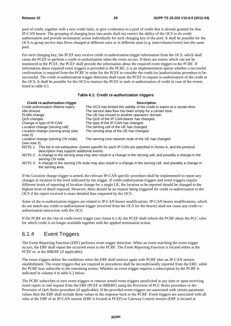
3GPP
3GPP TS 23.203 V10.6.0 (2012-03) 28Release 10
pool of credit, together with a new credit limit, or give a reference to a pool of credit that is already granted for that IP-CAN bearer. The grouping of charging keys into pools shall not restrict the ability of the OCS to do credit authorisation and provide termination action individually for each charging key of the pool. It shall be possible for the OCS to group service data flows charged at different rates or in different units (e.g. time/volume/event) into the same pool.
For each charging key, the PCEF may receive credit re-authorisation trigger information from the OCS, which shall cause the PCEF to perform a credit re-authorisation when the event occurs. If there are events which can not be monitored in the PCEF, the PCEF shall provide the information about the required event triggers to the PCRF. If information about required event triggers is provided to the PCRF, it is an implementation option whether a successful confirmation is required from the PCRF in order for the PCEF to consider the credit (re-)authorization procedure to be successful. The credit re-authorisation trigger detection shall cause the PCEF to request re-authorisation of the credit in the OCS. It shall be possible for the OCS to instruct the PCEF to seek re-authorisation of credit in case of the events listed in table 6.1.
Table 6.1: Credit re-authorization triggers
Credit re-authorization trigger Description Credit authorisation lifetime expiry The OCS has limited the validity of the credit to expire at a certain time. Idle timeout The service data flow has been empty for a certain time. PLMN change The UE has moved to another operators' domain. QoS changes The QoS of the IP-CAN bearer has changed. Change in type of IP-CAN The type of the IP-CAN has changed. Location change (serving cell) The serving cell of the UE has changed. Location change (serving area) (see note 2)
The serving area of the UE has changed.
Location change (serving CN node) (see note 3)
The serving core network node of the UE has changed.
NOTE 1: This list is not exhaustive. Events specific for each IP-CAN are specified in Annex A, and the protocol description may support additional events.
NOTE 2: A change in the serving area may also result in a change in the serving cell, and possibly a change in the serving CN node.
NOTE 3: A change in the serving CN node may also result in a change in the serving cell, and possibly a change in the serving area.
If the Location change trigger is armed, the relevant IP-CAN specific procedure shall be implemented to report any changes in location to the level indicated by the trigger. If credit-authorization triggers and event triggers require different levels of reporting of location change for a single UE, the location to be reported should be changed to the highest level of detail required. However, there should be no request being triggered for credit re-authorization to the OCS if the report received is more detailed than requested by the OCS.
Some of the re-authorization triggers are related to IP-CAN bearer modifications. IP-CAN bearer modifications, which do not match any credit re-authorization trigger (received from the OCS for the bearer) shall not cause any credit re-authorization interaction with the OCS.
If the PCRF set the Out of credit event trigger (see clause 6.1.4), the PCEF shall inform the PCRF about the PCC rules for which credit is no longer available together with the applied termination action.
6.1.4 Event Triggers The Event Reporting Function (ERF) performs event trigger detection. When an event matching the event trigger occurs, the ERF shall report the occurred event to the PCRF. The Event Reporting Function is located either at the PCEF or, at the BBERF (if applicable).
The event triggers define the conditions when the ERF shall interact again with PCRF after an IP-CAN session establishment. The event triggers that are required in procedures shall be unconditionally reported from the ERF, while the PCRF may subscribe to the remaining events. Whether an event trigger requires a subscription by the PCRF is indicated in column 4 in table 6.2 below.
The PCRF subscribes to new event triggers or remove armed event triggers unsolicited at any time or upon receiving event report or rule request from the ERF (PCEF or BBERF) using the Provision of PCC Rules procedure or the Provision of QoS Rules procedure (if applicable). If the provided event triggers are associated with certain parameter values then the ERF shall include those values in the response back to the PCRF. Event triggers are associated with all rules at the ERF of an IP-CAN session (ERF is located at PCEF) or Gateway Control session (ERF is located at
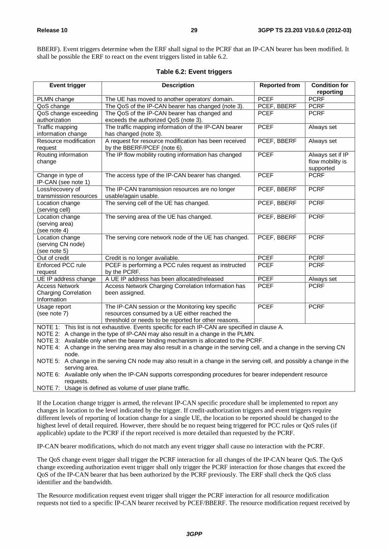
3GPP
3GPP TS 23.203 V10.6.0 (2012-03) 29Release 10
BBERF). Event triggers determine when the ERF shall signal to the PCRF that an IP-CAN bearer has been modified. It shall be possible the ERF to react on the event triggers listed in table 6.2.
Table 6.2: Event triggers
Event trigger Description Reported from Condition for reporting
PLMN change The UE has moved to another operators' domain. PCEF PCRF QoS change The QoS of the IP-CAN bearer has changed (note 3). PCEF, BBERF PCRF QoS change exceeding authorization
The QoS of the IP-CAN bearer has changed and exceeds the authorized QoS (note 3).
PCEF PCRF
Traffic mapping information change
The traffic mapping information of the IP-CAN bearer has changed (note 3).
PCEF Always set
Resource modification request
A request for resource modification has been received by the BBERF/PCEF (note 6).
PCEF, BBERF Always set
Routing information change
The IP flow mobility routing information has changed PCEF Always set if IP flow mobility is supported
Change in type of IP-CAN (see note 1)
The access type of the IP-CAN bearer has changed. PCEF PCRF
Loss/recovery of transmission resources
The IP-CAN transmission resources are no longer usable/again usable.
PCEF, BBERF PCRF
Location change (serving cell)
The serving cell of the UE has changed. PCEF, BBERF PCRF
Location change (serving area) (see note 4)
The serving area of the UE has changed. PCEF, BBERF PCRF
Location change (serving CN node) (see note 5)
The serving core network node of the UE has changed. PCEF, BBERF PCRF
Out of credit Credit is no longer available. PCEF PCRF Enforced PCC rule request
PCEF is performing a PCC rules request as instructed by the PCRF.
PCEF PCRF
UE IP address change A UE IP address has been allocated/released PCEF Always set Access Network Charging Correlation Information
Access Network Charging Correlation Information has been assigned.
PCEF PCRF
Usage report (see note 7)
The IP-CAN session or the Monitoring key specific resources consumed by a UE either reached the threshold or needs to be reported for other reasons.
PCEF PCRF
NOTE 1: This list is not exhaustive. Events specific for each IP-CAN are specified in clause A. NOTE 2: A change in the type of IP-CAN may also result in a change in the PLMN. NOTE 3: Available only when the bearer binding mechanism is allocated to the PCRF. NOTE 4: A change in the serving area may also result in a change in the serving cell, and a change in the serving CN
node. NOTE 5: A change in the serving CN node may also result in a change in the serving cell, and possibly a change in the
serving area. NOTE 6: Available only when the IP-CAN supports corresponding procedures for bearer independent resource
requests. NOTE 7: Usage is defined as volume of user plane traffic. If the Location change trigger is armed, the relevant IP-CAN specific procedure shall be implemented to report any changes in location to the level indicated by the trigger. If credit-authorization triggers and event triggers require different levels of reporting of location change for a single UE, the location to be reported should be changed to the highest level of detail required. However, there should be no request being triggered for PCC rules or QoS rules (if applicable) update to the PCRF if the report received is more detailed than requested by the PCRF.
IP-CAN bearer modifications, which do not match any event trigger shall cause no interaction with the PCRF.
The QoS change event trigger shall trigger the PCRF interaction for all changes of the IP-CAN bearer QoS. The QoS change exceeding authorization event trigger shall only trigger the PCRF interaction for those changes that exceed the QoS of the IP-CAN bearer that has been authorized by the PCRF previously. The ERF shall check the QoS class identifier and the bandwidth.
The Resource modification request event trigger shall trigger the PCRF interaction for all resource modification requests not tied to a specific IP-CAN bearer received by PCEF/BBERF. The resource modification request received by
3GPP
3GPP TS 23.203 V10.6.0 (2012-03) 30Release 10
PCEF/BBERF may include request for guaranteed bit rate changes for a traffic aggregate and/or the association/disassociation of a traffic aggregate with a QCI and/or a modification of a traffic aggregate.
The routing information change event trigger shall trigger the PCRF interaction for any change in how the IP flow is routed (i.e. IP flow mobility routing rules). The routing information change received by the PCEF is specified in TS 23.261 [23].
The enforced PCC rule request event trigger shall trigger a PCEF interaction to request PCC rules from the PCRF for an established IP-CAN session. This PCEF interaction shall take place within the Revalidation time limit set by the PCRF in the IP-CAN session related policy information (clause 6.4).
NOTE: This enforced PCC rule request mechanism can be used to avoid signalling overload situations e.g. due to time of day based PCC rule changes.
The UE IP address change event trigger applies to the PCEF only and shall trigger a PCEF interaction with the PCRF in case a UE IPv4 address is allocated or released during the lifetime of the IP-CAN session.
The Access Network Charging Correlation Information event shall trigger the PCEF to report the assigned access network charging identifier for the PCC rules that are accompanied with a request for this event at activation.
To activate usage monitoring, the PCRF shall set the Usage report event trigger and provide applicable usage thresholds for the Monitoring key(s) that are subject to usage monitoring in the PCEF. The PCRF shall not remove the Usage report event trigger while usage monitoring is still active in the PCEF.
If the Usage report event trigger is set and the volume thresholds, earlier provided by the PCRF, are reached, the PCEF shall report this event to the PCRF.
6.1.5 Policy Control Policy control comprises functionalities for:
- Binding, i.e. the generation of an association between a service data flow and the IP-CAN bearer transporting that service data flow;
- Gating control, i.e. the blocking or allowing of packets, belonging to a service data flow, to pass through to the desired endpoint;
- Event reporting, i.e. the notification of and reaction to application events to trigger new behaviour in the user plane as well as the reporting of events related to the resources in the GW(PCEF);
- QoS control, i.e. the authorisation and enforcement of the maximum QoS that is authorised for a service data flow or an IP-CAN bearer.
- IP-CAN bearer establishment for IP-CANs that support network initiated procedures for IP-CAN bearer establishment.
In case of an aggregation of multiple service data flows (e.g. for GPRS a PDP context), the combination of the authorised QoS information of the individual service data flows is provided as the authorised QoS for this aggregate.
The enforcement of the authorized QoS of the IP-CAN bearer may lead to a downgrading or upgrading of the requested bearer QoS by the GW(PCEF) as part of a UE-initiated IP-CAN bearer establishment or modification. Alternatively, the enforcement of the authorised QoS may, depending on operator policy and network capabilities, lead to network initiated IP-CAN bearer establishment or modification. If the PCRF provides authorized QoS for both, the IP-CAN bearer and PCC rule(s), the enforcement of authorized QoS of the individual PCC rules shall take place first.
QoS authorization information may be dynamically provisioned by the PCRF or, if the conditions mentioned in clause 6.3.1 apply, it can be a pre-defined PCC rule in the PCEF. In case the PCRF provides PCC rules dynamically, authorised QoS information for the IP-CAN bearer (combined QoS) may be provided. For a predefined PCC rules within the PCEF the authorized QoS information shall take affect when the PCC rule is activated. The PCEF shall combine the different sets of authorized QoS information, i.e. the information received from the PCRF and the information corresponding to the predefined PCC rules. The PCRF shall know the authorized QoS information of the predefined PCC rules and shall take this information into account when activating them. This ensures that the combined authorized QoS of a set of PCC rules that are activated by the PCRF is within the limitations given by the subscription and operator policies regardless of whether these PCC rules are dynamically provided, predefined or both.
3GPP
3GPP TS 23.203 V10.6.0 (2012-03) 31Release 10
For policy control, the AF interacts with the PCRF and the PCRF interacts with the PCEF as instructed by the AF. For certain events related to policy control, the AF shall be able to give instructions to the PCRF to act on its own, i.e. based on the service information currently available. The following events are subject to instructions from the AF:
- The authorization of the service based on incomplete service information;
NOTE 1: The QoS authorization based on incomplete service information is required for e.g. IMS session setup scenarios with available resources on originating side and a need for resource reservation on terminating side.
- The immediate authorization of the service;
- The gate control (i.e. whether there is a common gate handling per AF session or an individual gate handling per AF session component required);
- The forwarding of IP-CAN bearer level information or events:
- Type of IP-CAN (e.g. GPRS, I-WLAN, etc.);
- Transmission resource status (established/released/lost);
- Access Network Charging Correlation Information;
- Credit denied.
NOTE 2: The credit denied information is only relevant for AFs not performing service charging.
To enable the binding functionality, the UE and the AF shall provide all available flow description information (e.g. source and destination IP address and port numbers and the protocol information). The UE shall use the traffic mapping information to indicate downlink and uplink IP flows.
6.1.6 Service (data flow) Prioritization and Conflict Handling Service pre-emption priority enables the PCRF to resolve conflicts where the activation of all requested active PCC rules for services would result in a cumulative authorized QoS which exceeds the Subscribed Guaranteed bandwidth QoS.
For example, when supporting network controlled QoS, the PCRF may use the pre-emption priority of a service, the activation of which would cause the subscriber’s authorized QoS to be exceeded. If this pre-emption priority is greater than that of any one or more active PCC rules, the PCRF can determine whether the deactivation of any one or more such rules would allow the higher pre-emption priority PCC rule to be activated whilst ensuring the resulting cumulative QoS does not exceed a subscriber’s Subscribed Guaranteed Bandwidth QoS.
If such a determination can be made, the PCRF may resolve the conflict by deactivating those selected PCC rules with lower pre-emption priorities and accepting the higher priority service information from the AF. If such a determination cannot be made, the PCRF may reject the service information from the AF.
NOTE: Normative PCRF requirements for conflict handling are not defined. Alternative procedures may use a combination of pre-emption priority and AF provided priority indicator.
6.1.7 Standardized QoS characteristics
6.1.7.1 General
The service level (i.e., per SDF or per SDF aggregate) QoS parameters are QCI, ARP, GBR, and MBR.
Each Service Data Flow (SDF) is associated with one and only one QoS Class Identifier (QCI). For the same IP-CAN session multiple SDFs with the same QCI and ARP can be treated as a single traffic aggregate which is referred to as an SDF aggregate. An SDF is a special case of an SDF aggregate. The QCI is scalar that is used as a reference to node specific parameters that control packet forwarding treatment (e.g. scheduling weights, admission thresholds, queue management thresholds, link layer protocol configuration, etc.) and that have been pre-configured by the operator owning the node (e.g. eNodeB).
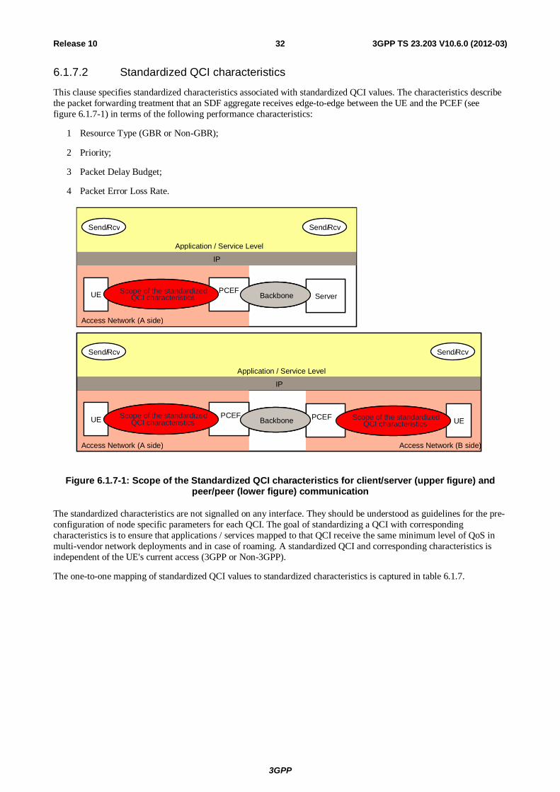
3GPP
3GPP TS 23.203 V10.6.0 (2012-03) 32Release 10
6.1.7.2 Standardized QCI characteristics
This clause specifies standardized characteristics associated with standardized QCI values. The characteristics describe the packet forwarding treatment that an SDF aggregate receives edge-to-edge between the UE and the PCEF (see figure 6.1.7-1) in terms of the following performance characteristics:
1 Resource Type (GBR or Non-GBR);
2 Priority;
3 Packet Delay Budget;
4 Packet Error Loss Rate.
Access Network (B side)
IP
Application / Service Level
Send/Rcv
Access Network (A side)
Send/Rcv
UE PDNGW
Scope of the standardized QCI characteristics UE PDN
GWScope of the standardized
QCI characteristicsBackbone
IP
Application / Service Level
Send/Rcv
Access Network (A side)
Send/Rcv
UE PDNGW
Scope of the standardized QCI characteristics Server Backbone
Access Network (B side)
IP
Application / Service Level
Send/Rcv
Access Network (A side)
Send/Rcv
UE PDNGW
Scope of the standardized QCI characteristics UE PDN
GWScope of the standardized
QCI characteristicsBackbone
Access Network (B side)
IP
Application / Service Level
Send/Rcv
Access Network (A side)
Send/Rcv
UE PDNGW
Scope of the standardized QCI characteristicsUE PCEFScope of the standardized QCI characteristics UE PDN
GWScope of the standardized
QCI characteristics UE PCEF Scope of the standardizedQCI characteristicsBackbone
IP
Application / Service Level
Send/Rcv
Access Network (A side)
Send/Rcv
UE PDNGW
Scope of the standardized QCI characteristics Server Backbone
IP
Application / Service Level
Send/Rcv
Access Network (A side)
Send/Rcv
UE PDNScope of the standardized QCI characteristicsUE PCEF Scope of the standardized QCI characteristics Server Backbone
Figure 6.1.7-1: Scope of the Standardized QCI characteristics for client/server (upper figure) and peer/peer (lower figure) communication
The standardized characteristics are not signalled on any interface. They should be understood as guidelines for the pre-configuration of node specific parameters for each QCI. The goal of standardizing a QCI with corresponding characteristics is to ensure that applications / services mapped to that QCI receive the same minimum level of QoS in multi-vendor network deployments and in case of roaming. A standardized QCI and corresponding characteristics is independent of the UE's current access (3GPP or Non-3GPP).
The one-to-one mapping of standardized QCI values to standardized characteristics is captured in table 6.1.7.
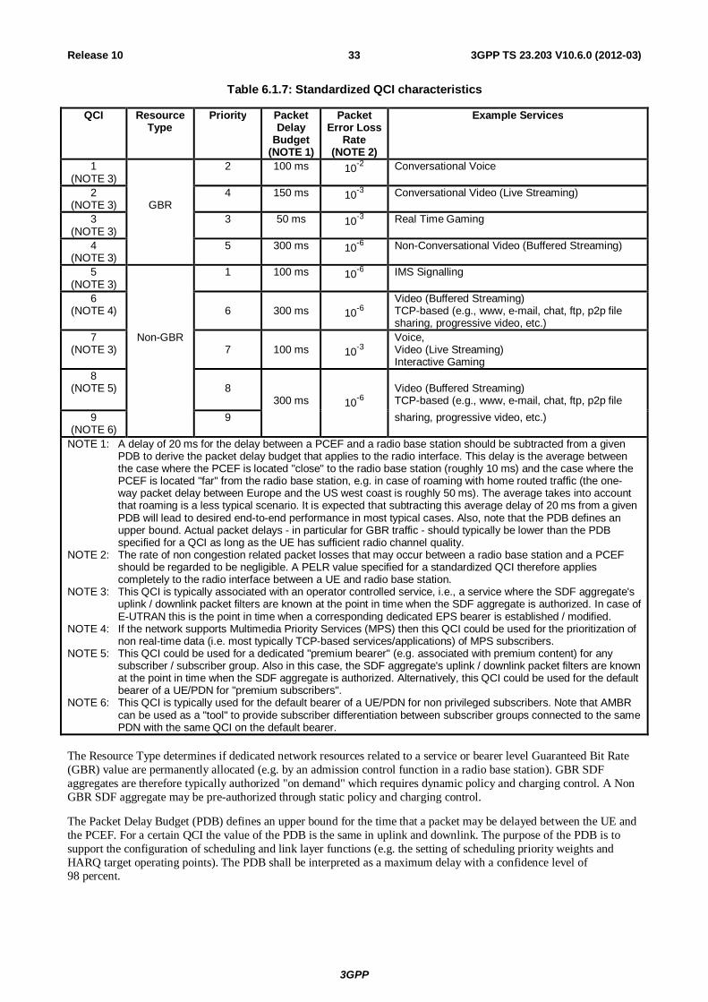
3GPP
3GPP TS 23.203 V10.6.0 (2012-03) 33Release 10
Table 6.1.7: Standardized QCI characteristics
QCI Resource Type
Priority Packet Delay
Budget (NOTE 1)
Packet Error Loss
Rate (NOTE 2)
Example Services
1 (NOTE 3)
2 100 ms 10-2 Conversational Voice
2 (NOTE 3)
GBR
4 150 ms 10-3 Conversational Video (Live Streaming)
3 (NOTE 3)
3 50 ms 10-3 Real Time Gaming
4 (NOTE 3)
5 300 ms 10-6 Non-Conversational Video (Buffered Streaming)
5 (NOTE 3)
1 100 ms 10-6 IMS Signalling
6 (NOTE 4)
6
300 ms
10-6
Video (Buffered Streaming) TCP-based (e.g., www, e-mail, chat, ftp, p2p file sharing, progressive video, etc.)
7 (NOTE 3)
Non-GBR 7
100 ms
10-3
Voice, Video (Live Streaming) Interactive Gaming
8 (NOTE 5)
8
300 ms
10-6
Video (Buffered Streaming) TCP-based (e.g., www, e-mail, chat, ftp, p2p file
9 (NOTE 6)
9 sharing, progressive video, etc.)
NOTE 1: A delay of 20 ms for the delay between a PCEF and a radio base station should be subtracted from a given PDB to derive the packet delay budget that applies to the radio interface. This delay is the average between the case where the PCEF is located "close" to the radio base station (roughly 10 ms) and the case where the PCEF is located "far" from the radio base station, e.g. in case of roaming with home routed traffic (the one-way packet delay between Europe and the US west coast is roughly 50 ms). The average takes into account that roaming is a less typical scenario. It is expected that subtracting this average delay of 20 ms from a given PDB will lead to desired end-to-end performance in most typical cases. Also, note that the PDB defines an upper bound. Actual packet delays - in particular for GBR traffic - should typically be lower than the PDB specified for a QCI as long as the UE has sufficient radio channel quality.
NOTE 2: The rate of non congestion related packet losses that may occur between a radio base station and a PCEF should be regarded to be negligible. A PELR value specified for a standardized QCI therefore applies completely to the radio interface between a UE and radio base station.
NOTE 3: This QCI is typically associated with an operator controlled service, i.e., a service where the SDF aggregate's uplink / downlink packet filters are known at the point in time when the SDF aggregate is authorized. In case of E-UTRAN this is the point in time when a corresponding dedicated EPS bearer is established / modified.
NOTE 4: If the network supports Multimedia Priority Services (MPS) then this QCI could be used for the prioritization of non real-time data (i.e. most typically TCP-based services/applications) of MPS subscribers.
NOTE 5: This QCI could be used for a dedicated "premium bearer" (e.g. associated with premium content) for any subscriber / subscriber group. Also in this case, the SDF aggregate's uplink / downlink packet filters are known at the point in time when the SDF aggregate is authorized. Alternatively, this QCI could be used for the default bearer of a UE/PDN for "premium subscribers".
NOTE 6: This QCI is typically used for the default bearer of a UE/PDN for non privileged subscribers. Note that AMBR can be used as a "tool" to provide subscriber differentiation between subscriber groups connected to the same PDN with the same QCI on the default bearer.
The Resource Type determines if dedicated network resources related to a service or bearer level Guaranteed Bit Rate (GBR) value are permanently allocated (e.g. by an admission control function in a radio base station). GBR SDF aggregates are therefore typically authorized "on demand" which requires dynamic policy and charging control. A Non GBR SDF aggregate may be pre-authorized through static policy and charging control.
The Packet Delay Budget (PDB) defines an upper bound for the time that a packet may be delayed between the UE and the PCEF. For a certain QCI the value of the PDB is the same in uplink and downlink. The purpose of the PDB is to support the configuration of scheduling and link layer functions (e.g. the setting of scheduling priority weights and HARQ target operating points). The PDB shall be interpreted as a maximum delay with a confidence level of 98 percent.
3GPP
3GPP TS 23.203 V10.6.0 (2012-03) 34Release 10
NOTE 1: The PDB denotes a "soft upper bound" in the sense that an "expired" packet, e.g. a link layer SDU that has exceeded the PDB, does not need to be discarded (e.g. by RLC in E-UTRAN). The discarding (dropping) of packets is expected to be controlled by a queue management function, e.g. based on pre-configured dropping thresholds.
The support for SRVCC requires QCI=1 only be used for IMS speech sessions in accordance to TS 23.216 [27].
NOTE 2: Triggering SRVCC will cause service interruption and/or inconsistent service experience when using QCI=1 for non-IMS services.
Services using a Non-GBR QCI should be prepared to experience congestion related packet drops, and 98 percent of the packets that have not been dropped due to congestion should not experience a delay exceeding the QCI's PDB. This may for example occur during traffic load peaks or when the UE becomes coverage limited. See Annex J for details. Packets that have not been dropped due to congestion may still be subject to non congestion related packet losses (see PELR below).
Services using a GBR QCI and sending at a rate smaller than or equal to GBR can in general assume that congestion related packet drops will not occur, and 98 percent of the packets shall not experience a delay exceeding the QCI's PDB. Exceptions (e.g. transient link outages) can always occur in a radio access system which may then lead to congestion related packet drops even for services using a GBR QCI and sending at a rate smaller than or equal to GBR. Packets that have not been dropped due to congestion may still be subject to non congestion related packet losses (see PELR below).
Every QCI (GBR and Non-GBR) is associated with a Priority level. Priority level 1 is the highest Priority level. The Priority levels shall be used to differentiate between SDF aggregates of the same UE, and it shall also be used to differentiate between SDF aggregates from different UEs. Via its QCI an SDF aggregate is associated with a Priority level and a PDB. Scheduling between different SDF aggregates shall primarily be based on the PDB. If the target set by the PDB can no longer be met for one or more SDF aggregate(s) across all UEs that have sufficient radio channel quality then Priority shall be used as follows: in this case a scheduler shall meet the PDB of an SDF aggregate on Priority level N in preference to meeting the PDB of SDF aggregates on Priority level N+1 until the priority N SDF aggregate's GBR (in case of a GBR SDF aggregate) has been satisfied. Other aspects related to the treatment of traffic exceeding an SDF aggregate's GBR are out of scope of this specification.
NOTE 3: The definition (or quantification) of "sufficient radio channel quality" is out of the scope of 3GPP specifications.
NOTE 4: In case of E-UTRAN a QCI's Priority level may be used as the basis for assigning the uplink priority per Radio Bearer (see TS 36.300 [19] for details).
The Packet Error Loss Rate (PELR) defines an upper bound for the rate of SDUs (e.g. IP packets) that have been processed by the sender of a link layer protocol (e.g. RLC in E-UTRAN) but that are not successfully delivered by the corresponding receiver to the upper layer (e.g. PDCP in E-UTRAN). Thus, the PELR defines an upper bound for a rate of non congestion related packet losses. The purpose of the PELR is to allow for appropriate link layer protocol configurations (e.g. RLC and HARQ in E-UTRAN). For a certain QCI the value of the PELR is the same in uplink and downlink.
NOTE 5: The characteristics PDB and PELR are specified only based on application / service level requirements, i.e., those characteristics should be regarded as being access agnostic, independent from the roaming scenario (roaming or non-roaming), and independent from operator policies.
6.1.7.3 Allocation and Retention Priority characteristics
The QoS parameter ARP contains information about the priority level, the pre-emption capability and the pre-emption vulnerability. The priority level defines the relative importance of a resource request. This allows deciding whether a bearer establishment or modification request can be accepted or needs to be rejected in case of resource limitations (typically used for admission control of GBR traffic). It can also be used to decide which existing bearers to pre-empt during resource limitations.
The range of the ARP priority level is 1 to 15 with 1 as the highest level of priority. The pre-emption capability information defines whether a service data flow can get resources that were already assigned to another service data flow with a lower priority level. The pre-emption vulnerability information defines whether a service data flow can lose the resources assigned to it in order to admit a service data flow with higher priority level. The pre-emption capability and the pre-emption vulnerability can be either set to 'yes' or 'no'.
3GPP
3GPP TS 23.203 V10.6.0 (2012-03) 35Release 10
The ARP priority levels 1-8 should only be assigned to resources for services that are authorized to receive prioritized treatment within an operator domain (i.e. that are authorized by the serving network). The ARP priority levels 9-15 may be assigned to resources that are authorized by the home network and thus applicable when a UE is roaming.
NOTE: This ensures that future releases may use ARP priority level 1-8 to indicate e.g. emergency and other priority services within an operator domain in a backward compatible manner. This does not prevent the use of ARP priority level 1-8 in roaming situation in case appropriate roaming agreements exist that ensure a compatible use of these priority levels.
6.1.8 Termination Action The termination action applies only in case of online charging. The termination action indicates the action, which the PCEF should perform when no more credit is granted. A packet that matches a PCC rule, indicating a charging key for which no credit has been granted, is subject to a termination action.
The defined termination actions include:
- Allowing the packets to pass through;
- Dropping the packets;
- The PCEF Default Termination Action;
- The re-direction of packets to an application server (e.g. defined in the termination action).
NOTE 1: Such a re-direction may cause an application protocol specific asynchronous close event and application protocol specific procedures may be required in the UE and/or AF in order to recover, e.g. as specified in RFC 2616 for HTTP.
The Default Termination Action for all charging keys, for which no more credit is granted and there is no specific termination action shall be pre-configured in the PCEF according to operator's policy. For instance, the default behaviour may consist of allowing packets of any terminated service data flow to pass through the PCEF.
The OCS may provide a termination action for each charging key over the Gy interface. Any previously provided termination action may be overwritten by the OCS. A termination action remains valid and shall be applied by the PCEF until all the corresponding PCC rules of that charging key are removed or the corresponding IP-CAN bearer is removed (for GPRS the PDP context).
The OCS shall provide the termination action to the PCEF before denying credit; otherwise the PCEF default termination action will be performed.
6.1.9 Handling of packet filters provided to the UE by PCEF/BBERF The network shall ensure that the traffic mapping information negotiated with the UE reflects the bearer binding of PCC/QoS rules, except for those extending the inspection beyond what can be signalled to the UE. The PCC/QoS rules may restrict what traffic is allowed compared to what is explicitly negotiated with the UE. The PCRF may, per service data flow filter, indicate that the PCEF/BBERF is required to explicitly signal the corresponding traffic mapping information to the UE, e.g. for the purpose of IMS precondition handling at the UE. In absence of that indication, it is a PCEF/BBERF decision whether to signal the traffic mapping information that is redundant from a traffic mapping point of view.
NOTE 1: A new/modified PCC/QoS rule can cause that previously redundant, and therefore omitted, traffic mapping information to cease being redundant and causing the PCEF/BBERF to signal the corresponding traffic mapping information to the UE.
NOTE 2: In order to signal a specific traffic mapping to a PDP context/EPS bearer without any previous TFT, if the operator policy is to continue allowing previously allowed traffic on that bearer, TFT filters that correspond to the previous traffic mapping need to be introduced as well.
NOTE 3: The PCEF/BERF can use all SDF filters for the generation of traffic mapping information. However if the number of SDF filters for an IP-CAN bearer exceeds the maximum number of filters that may be signalled to the UE (e.g. as specified in TS 24.008) another bearer needs to be established and a rebinding of PCC rules to bearers (by PCEF/BBERF) or even the splitting of the SDF template into two or more PCC rules (by PCRF) may be required.
3GPP
3GPP TS 23.203 V10.6.0 (2012-03) 36Release 10
The traffic mapping information (e.g. TFT filters for GPRS and EPS) that the network provides to the UE shall include the same content as the corresponding SDF filters in the SDF template received over the Gx/Gxx interface. The representation/format of the packet filters provided by the network to the UE is access-system dependent and may vary between accesses and may also be different from the representation/format of the SDF filters in the SDF template on the Gx/Gxx interface.
NOTE 4: After handover from one access-system to another, if the UE needs to determine the QoS provided in the target access to the pre-existing IP flows in the source access, the UE can perform packet filter comparison between the packet filters negotiated in the old access and those provided by the target access during QoS resource activation.
NOTE 5: If UE initiated procedures are supported and handover between access systems is to be supported, the content of the packet filters provided on the Gx/Gxx interface by the PCRF is restricted to the packet filter fields that all the accesses can provide to the UE.
6.1.10 IMS Emergency Session Support
6.1.10.1 Architecture model and Reference points
Emergency bearer services (i.e. IP-CAN session for the IMS emergency call) are provided by the serving network to support IMS emergency when the network is configured to support emergency services. Emergency services are network services provided through an Emergency APN and may not require a subscription depending on operator policies and local regulatory requirements. For emergency services the architecture for the non-roaming case as described in clause 5.1 is the only applicable architecture model.
For emergency services, the Sp reference point does not apply.
Emergency services are handled locally in the serving network. Therefore the S9 reference point does not apply.
6.1.10.2 PCC Rule Authorization and QoS rule generation
The PCC Rule Authorization and QoS Rule generation function selects QoS parameters that allow prioritization of IMS Emergency calls. If an IMS Emergency call is prioritized the QoS parameters shall contain an ARP value that is reserved for intra-operator use of IMS Emergency calls.
6.1.10.3 Functional Entities
6.1.10.3.1 PCRF
The PCRF shall determine based on the PDN-id if an IP-CAN Session concerns an IMS emergency session (e.g. emergency call or PSAP callback).
For an IP-CAN session serving an IMS emergency session, the PCRF makes authorization and policy decisions that restricts the traffic to emergency destinations, IMS signalling and the traffic to retrieve user location information (in the user plane) for emergency services. An IP-CAN session serving an IMS emergency session shall not serve any other service and shall not be converted to/from any IP-CAN session serving other services.
If the UE IP address belongs to an emergency APN, the PCRF does not perform subscription check; instead it utilizes the locally configured operator policies to make authorization and policy decisions.
For IMS, it shall be possible for the PCRF to verify that the IMS service information is associated with a UE IP address belonging to an emergency APN. If the IMS service information does not contain an emergency related indication and the UE IP address is associated with an emergency APN, the PCRF shall reject the IMS service information provided by the P-CSCF (and thus to trigger the release of the associated IMS session), see TS 23.167 [21].
The PCRF performs according to existing procedure:
- If IMS service information containing an emergency related indication is received from the P-CSCF with an UE IP address associated to an Emergency APN, the PCRF initiates an IP-CAN session Modification Request for the IP-CAN session serving the IMS session to the PCEF to provide PCC Rule(s) that authorize media flow(s).
3GPP
3GPP TS 23.203 V10.6.0 (2012-03) 37Release 10
- At reception of an indication that the IMS emergency session is released from the P-CSCF, the PCRF removes the PCC rule(s) for that IMS session with an IP-CAN session Modification Request.
6.1.10.3.2 PCEF
The PCEF initiates the IP-CAN Session termination if the last PCC rule for this IP-CAN session is removed according to existing procedure.
In addition, at reception of an IP-CAN Session Modification Request triggered by the PCRF for an IP-CAN session serving an IMS emergency session that removes all PCC rules with a QCI other than the default bearer QCI and the QCI used for IMS signalling, the PCEF shall start a configurable inactivity timer (e.g., to enable PSAP Callback session). When the configured period of time expires the PCEF shall initiate an IP-CAN Session Termination Request for the IP-CAN session serving the IMS Emergency session.
NOTE: The configurable inactivity timer has identical value as when no PCC is used.
If a PCRF-Initiated IP-CAN Session Modification Request, providing new PCC rule(s) with a QCI other than the default bearer QCI and the QCI used for IMS signalling, the PCEF shall cancel the inactivity timer.
6.1.10.3.3 P-CSCF
The P-CSCF performs according to existing procedure:
- At reception of an indication that an IMS emergency session is established (e.g. Emergency call or for a PSAP callback session), the P-CSCF sends IMS service information to the PCRF.
- At reception of an indication that an IMS emergency session is released, the P-CSCF interacts with the PCRF to revoke the IMS service information.
In addition, the P-CSCF shall include an emergency related indication when providing IMS service information to the PCRF; see TS 23.167 [21].
6.1.10.4 PCC Procedures and Flows
At Indication of IP-CAN Session Establishment that includes a PDN-id that identifies an Emergency APN the PCRF ignores subscription information from the SPR. The PCRF uses locally configured operator policies to make authorization and policy decisions.
At Indication of IP-CAN Session Establishment and Gateway Control Session Establishment, the user identity (e.g. IMSI) may not be available, or can not be authenticated. In this case, the IMEI shall be used to identify the UE.
An IP-CAN session for an emergency service shall be restricted to the destination address(es) associated with the emergency service only.
6.1.11 Multimedia Priority Service Support
6.1.11.1 Architecture model and Reference points
Subscription data for MPS is provided to PCC through the Sp reference point. To support MPS service, the PCRF shall subscribe to changes in the MPS subscription data for Priority EPS Bearer Service. Dynamic invocation for MPS is provided from an AF, using the Priority indicator, over Rx.
6.1.11.2 PCC rule authorization and QoS rule generation
For MPS service, the PCRF shall generate the corresponding PCC/QoS rule(s) with the ARP/QCI parameters as appropriate for the prioritized service.
For non-MPS service, the PCRF shall generate the corresponding PCC/QoS rule(s) as per normal procedures, without consideration whether the MPS Priority EPS Bearer Service is active or not, but upgrade the ARP/QCI values suitable for MPS when the Priority EPS Bearer Service is invoked. When the priority EPS Bearer Service is revoked, the PCRF shall change ARP/QCI values modified for Priority EPS bearer service to an appropriate value according to PCRF decision.
3GPP
3GPP TS 23.203 V10.6.0 (2012-03) 38Release 10
6.1.11.3 Priority EPS Bearer Service
The MPS Priority EPS Bearer Service targets the ARP and/or QCI of bearer(s), enabling the prioritization of all traffic on the same bearer.
The PCRF shall, at the activation of the Priority EPS Bearer Service:
- modify ARP/QCI of the default bearer; and
- modify the ARP/QCI of PCC/QoS Rules installed before the activation of the Priority EPS Bearer Service to the ARP/QCI as appropriate for the Priority EPS Bearer Service.
The PCRF shall, at the deactivation of the Priority EPS Bearer Service:
- apply the normal ARP/QCI to the default bearer; and
- for PCC/QoS rules, change ARP/QCI values modified for Priority EPS bearer service to an appropriate value according to PCRF decision.
6.1.11.4 Bearer priority for IMS Multimedia Priority Services
In addition to the mechanism specified in clause 6.1.11.2, IMS Multimedia Priority Services may require upgrade of the dedicated IM CN signalling bearer and the default bearer, e.g. in order to mitigate the IP-CAN session termination due to resource limitation at a location change the default bearer and dedicated IM CN signalling bearer may need an upgraded ARP.
The PCRF shall, at reception of the indication that the IMS Signalling Priority is set for the IP-CAN Session or at reception of service authorization from the P-CSCF (AF) including an MPS session indication and the service priority level:
- assign/upgrade the required ARP to the default bearer; and
- if upgrade of the dedicated IM CN signalling bearer is required, change the ARP in all the PCC/QoS rules that describe the IM CN signalling traffic to the value appropriate for IMS Multimedia Priority Services active.
When the PCRF detects that the P-CSCF (AF) released all the MPS session and the IMS Signalling Priority is not set for the IP-CAN session the PCRF shall:
- apply ARP of the default bearer appropriate with the IMS Multimedia; and
- for PCC/QoS rules, apply an ARP value appropriate with the IMS Multimedia to the PCC/QoS Rule that describe the IM CN signalling traffic.
6.2 Functional entities
6.2.1 Policy Control and Charging Rules Function (PCRF)
6.2.1.0 General
The PCRF encompasses policy control decision and flow based charging control functionalities.
The PCRF provides network control regarding the service data flow detection, gating, QoS and flow based charging (except credit management) towards the PCEF.
The PCRF shall apply the security procedures, as required by the operator, before accepting service information from the AF.
The PCRF shall decide how a certain service data flow shall be treated in the PCEF, and ensure that the PCEF user plane traffic mapping and treatment is in accordance with the user's subscription profile.
If Gxx applies, the PCRF shall provide QoS rules with identical service data flow templates as provided to the PCEF in the PCC rules. If the service data flow is tunnelled at the BBERF, the PCRF shall provide the BBERF with information received from the PCEF to enable the service data flow detection in the mobility tunnel at the BBERF. In case 2a,
3GPP
3GPP TS 23.203 V10.6.0 (2012-03) 39Release 10
defined in clause 7.1, the PCRF may also provide to the BBERF the charging ID information received from the PCEF. When IP flow mobility scenarios are supported as specified in TS 23.261 [23] if the PCRF receives IP flow mobility routing rules from the PCEF, it shall provide authorized QoS rules to the applicable BBERF as specified in clause 6.1.1.3.
The PCRF should for an IP-CAN session derive, from IP-CAN specific restrictions, operator policy and SPR data, the list of permitted QoS class identifiers and associated GBR and MBR limits for the IP-CAN session.
The PCRF may check that the service information provided by the AF is consistent with both the operator defined policy rules and the related subscription information as received from the SPR during IP-CAN session establishment before storing the service information. The service information shall be used to derive the QoS for the service. The PCRF may reject the request received from the AF when the service information is not consistent with either the related subscription information or the operator defined policy rules and as a result the PCRF shall indicate that this service information is not covered by the subscription information or by operator defined policy rules and may indicate, in the response to the AF, the service information that can be accepted by the PCRF (e.g. the acceptable bandwidth). In the absence of other policy control mechanisms outside the scope of PCC, it is recommended that the PCRF include this information in the response.
In this Release, the PCRF supports only a single Rx reference point, i.e. there is one AF for each AF session.
The PCRF authorizes QoS resources. The PCRF uses the service information received from the AF (e.g. SDP information or other available application information) and/or the subscription information received from the SPR to calculate the proper QoS authorization (QoS class identifier, bitrates). The PCRF may also take into account the requested QoS received from the PCEF via Gx interface.
NOTE 1: The PCRF provides always the maximum values for the authorized QoS even if the requested QoS is lower than what can be authorized.
The Authorization of QoS resources shall be based on complete service information unless the PCRF is required to perform the authorization of QoS resources based on incomplete service information. The PCRF shall after receiving the complete service information, update the affected PCC rules accordingly.
The PCRF may use the subscription information as basis for the policy and charging control decisions. The subscription information may apply for both session based and non-session based services.
The PCRF determines whether a Gx session from the PCEF is to be linked with a Gateway Control Session from the BBERF by matching the IPv4 address and/or IPv6 network prefix and conditionally the UE Identity, PDN Connection ID and PDN ID towards open Gateway Control Sessions. When IP flow mobility as specified in TS 23.261 [23] applies, one Gx session may be linked with multiple Gateway Control Sessions.
If the BBERF does not provide any PDN ID at the Gateway Control Session Establishment, then the PCRF maintains Gateway Control Session to Gx session linking to the Gx sessions where the assigned CoA and UE Identity (if available over Gxx) are equal. The PCRF and BBERF shall be capable of separating information for each IP-CAN session within the common Gateway Control Session.
If the BBERF provides a PDN ID at the Gateway Control Session Establishment, then the PCRF maintains Gateway Control Session to Gx session linking where the UE identity and PDN ID are equal. If the BBERF provides a PDN ID at Gateway Control Session establishment, it may also indicate in the Gateway Control Session establishment that the PCRF shall not attempt linking the new Gateway Control Session with an existing Gx session immediately. If the PCRF receives such an indication, it keeps the new Gateway Control Session pending and defers linking until an IP-CAN session establishment or an IP-CAN session modification with matching UE Identity, PDN ID and IP-CAN type arrives via Gx.
If the BBERF provides a PDN ID and a PDN Connection ID at the Gateway Control Session establishment, then the PCRF maintains Gateway Control Session to Gx session linking where the UE identity, PDN Connection ID and PDN ID are equal.
When a BBERF establishes multiple Gateway Control Sessions for the same PDN ID and the IP-CAN type changes, the PCRF assumes that this constitutes inter-system BBERF relocations of existing Gateway Control Sessions. The BBERF may supply UE IPv4 address and/or IPv6 network prefix (if known) that can be used for linking the new Gateway Control Session to the existing Gx session. If the UE IPv4 address and/or IPv6 network prefix is/are not provided in the new Gateway Control Session establishment, the PCRF shall defer the linking with existing Gx session until receiving an IP-CAN Session modification with matching UE Identity, IP-CAN type, PDN Connection ID, and PDN ID.
The PCRF determines which case applies as described on clause 7.1.
3GPP
3GPP TS 23.203 V10.6.0 (2012-03) 40Release 10
If an AF requests the PCRF to report on the signalling path status, for the AF session, the PCRF shall, upon indication of loss of resources from the PCEF, for PCC rules corresponding to the signalling traffic notify the AF on changes to the signalling path status. The PCRF needs to have the knowledge of which PCC rules identify signalling traffic.
Negotiation of IP-CAN bearer establishment mode takes place via Gx for 3GPP IP-CANs. For non-3GPP IP-CANs specified in TS 23.402 [18] negotiation of bearer establishment mode takes place via Gx when GTP is used and via Gxx for the rest of the cases. For other accesses supporting multiple IP-CAN bearer establishment modes, if Gxx applies, the negotiation takes place via Gxx, otherwise via Gx. To support the different IP-CAN bearer establishment modes (UE-only or UE/NW) the PCRF shall:
- shall set the IP-CAN bearer establishment mode for the IP-CAN session based on operator configuration, network and UE capabilities;
- shall, if the bearer establishment mode is UE/NW, decide what mode (UE or NW) shall apply for a PCC rule and resolve race conditions between for requests between UE-initiated and NW-initiated requests;
NOTE 2: For an operator-controlled service, the UE and the PCRF may be provisioned with information indicating which mode is to be used.
- may reject a UE request that is already served by a NW-initiated procedure in progress. When rejecting a UE-initiated request by sending a reject indication, the PCRF shall use an appropriate cause value which shall be delivered to the UE.
NOTE 3: This situation may e.g. occur if the PCRF has already triggered a NW-initiated procedure that corresponds to the UE request.
- guarantee the precedence of dynamic PCC rules for network controlled services in the service data flow detection process at the PCEF by setting the PCC rule precedence information to appropriate values.
If an AF requests the PCRF to report on the change of type of IP-CAN, the PCRF shall provide to the AF the information about the IP-CAN type the user is currently using and upon indication of change of IP-CAN type, notify the AF on changes of the type of IP-CAN. In the case of 3GPP IP-CAN, the information of the Radio Access Technology Type (e.g. UTRAN) shall be also reported to the AF. If IP flow mobility as specified in TS 23.261 [23] applies, the PCRF shall provide to the AF the IP-CAN type information about the IP-CAN type the service data flow currently transported within and upon indication of change of IP-CAN type, notify the AF on changes of the type of IP-CAN. In the case of 3GPP IP-CAN, the information of the Radio Access Technology Type (e.g. UTRAN) shall be also reported to the AF. When IP flow mobility is allowed within the same IP-CAN session, the PCRF shall only report the IP-CAN type change when the IP flow mobility applies to the service information provided by the AF.
If an AF requests the PCRF to report Access Network Charging Correlation Information, the PCRF shall provide to the AF the Access Network Charging Correlation Information, that will identify the usage reports that include measurement for the flows, once the Access Network Charging Correlation Information is known at the PCRF. If not known in advance, the PCRF subscribes for the Access Network Charging Correlation Information event for the applicable PCC rule(s).
If Gxx applies and the PCEF provided information about required event triggers, the PCRF shall provide these event triggers to the BBERF and notify the PCEF of the outcome of the provisioning procedure by using the PCRF initiated IP-CAN Session Modification procedure, as defined in clause 7.4.2. The PCRF shall include the parameter values received in the response from the BBERF in the notification to the PCEF. When multiple BBERFs exist (e.g. in IP flow mobility case), the PCEF may subscribe to different or common set of event triggers at different BBERFs; when the PCRF receives event notification from any BBERF, the PCRF shall include both the parameters values received from the BBERF and also the information for identifying the BBERF in the notification to the PCEF.
When the PCRF gets an event report from the BBERF that is required by the PCEF, the PCRF shall forward this event report to the PCEF.
The PCRF may support usage monitoring control. Usage is defined as volume of user plane traffic.
The PCRF may receive information about total allowed usage per PDN and UE from the SPR, i.e. the overall amount of allowed resources (traffic volume) that are to be monitored for the PDN connections of a user. In addition information about total allowed usage for Monitoring key(s) per PDN and UE may also be received from the SPR.
The PCRF may authorise an application service provider to request specific PCC decisions (e.g. authorisation to request sponsored IP flows, authorisation to request QoS resources)
3GPP
3GPP TS 23.203 V10.6.0 (2012-03) 41Release 10
For the purpose of usage monitoring control the PCRF shall request the Usage report trigger and provide the necessary usage threshold(s) upon which the PCEF shall report to the PCRF.
It shall be possible for the PCRF to request a usage report from the PCEF containing the accumulated volume usage since the time of the last usage report.
Once the PCRF receives a usage report from the PCEF, the PCRF shall deduct the value of the usage report from the totally allowed usage for that PDN and UE (in case usage per IP-CAN session is reported) or from the totally allowed usage for individual Monitoring key(s) for that PDN and UE (in case of usage for one or several Monitoring keys is reported).
NOTE 4: The PCRF maintains usage thresholds for each Monitoring key and IP-CAN session that is active for a certain PDN and UE. Updating the total allowanced usage after the PCEF reporting, minimizes the risk of exceeding the usage allowance.
If the PCEF reports usage for a certain Monitoring key and if monitoring shall continue for that Monitoring key then the PCRF shall provide new threshold values in the response to the PCEF.
If monitoring shall no longer continue for that Monitoring key, then the PCRF shall not provide a new threshold in the response to the PCEF.
NOTE 5: If the PCRF decides to deactivate all PCC-rules associated with a certain Monitoring key, then the conditions defined in clause 6.6.2 for continued Monitoring will no longer be fulfilled for that Monitoring key.
If all IP-CAN session of a user to the same APN is terminated, the PCRF shall store the remaining allowed usage, i.e. the information about the remaining overall amount of resources, in the SPR.
For sponsored data connectivity (see Annex N), the PCRF may receive a usage threshold from the AF.
If the AF specifies a usage threshold, the PCRF shall use the Sponsor Identity to construct a Monitoring key for monitoring the volume of user plane traffic, and invoke usage monitoring on the PCEF. The PCRF shall notify the AF when the PCEF reports that a usage threshold for the Monitoring key is reached provided that the AF requests to be notified for this event. If the usage threshold is reached, the AF may terminate the AF session or provide a new usage threshold to the PCRF. Alternatively, the AF may allow the session to continue without specifying a usage threshold. If the AF decides to allow the session to continue without specifying a usage threshold, then monitoring in the PCEF shall be discontinued for that monitoring key by the PCRF, unless there are other reasons for continuing the monitoring.
If the AF revokes the service information and the AF has notified previously a usage threshold to the PCRF, the PCRF shall report the usage up to the time of the revocation of service authorization.
If the IP-CAN session terminates and the AF has specified a usage threshold then the PCRF shall notify the AF of the consumed volume of user plane traffic since the last usage report.
The PCRF performs authorizations based on sponsored data connectivity profiles stored in the SPR. If the AF is in the operator's network and is based on the OSA/Parlay-X GW (TS 23.198 [24]), the PCRF is not required to verify that a trust relationship exists between the operator and the sponsors.
If the H-PCRF detects that the UE is accessing the sponsored data connectivity in the roaming scenario with home routed access, it may allow the sponsored data connectivity in the service authorization request, reject the service authorization request, or initiate the AF session termination based on home operator policy.
NOTE 6: Sponsored data connectivity is not supported in the roaming with visited access scenario in this Release.
6.2.1.1 Input for PCC decisions
The PCRF shall accept input for PCC decision-making from the PCEF, the BBERF if present, the SPR and if the AF is involved, from the AF, as well as the PCRF may use its own pre-defined information. These different nodes should provide as much information as possible to the PCRF. At the same time, the information below describes examples of the information provided. Depending on the particular scenario all the information may not be available or is already provided to the PCRF.
The PCEF and/or BBERF may provide the following information:
- Subscriber Identifier;
3GPP
3GPP TS 23.203 V10.6.0 (2012-03) 42Release 10
- IPv4 address of the UE;
- IPv6 network prefix assigned to the UE;
- IP flow routing information (if IP flow mobility is used)
NOTE 1: This information is provided only by the PCEF
- IP-CAN bearer attributes;
- Request type (initial, modification, etc.);
- Type of IP-CAN (e.g. GPRS, I-WLAN, etc.);
NOTE 2: The Type of IP-CAN parameter should allow extension to include new types of accesses.
- Location of the subscriber;
NOTE 3: See clause 6.1.4 for the description of this location information.
- A PDN ID;
- A PLMN identifier;
- IP-CAN bearer establishment mode.
NOTE 4: Depending on the type of IP-CAN, the limited update rate for the location information at the PCEF may lead to a UE moving outside the area indicated in the detailed location information without notifying the PCEF.
The SPR may provide the following information for a subscriber, connecting to a specific PDN:
- Subscriber's allowed services, i.e. list of Service IDs;
- For each allowed service, a pre-emption priority;
- Information on subscriber's allowed QoS, including:
- the Subscribed Guaranteed Bandwidth QoS;
- a list of QoS class identifiers together with the MBR limit and, for real-time QoS class identifiers, GBR limit.
- Subscriber's charging related information;
- Subscriber category;
- Subscriber's usage monitoring related information;
- Sponsored data connectivity profiles;
- MPS EPS Priority, MPS Priority Level (See TS 23.401 [17] for more detail on MPS Subscription);
- IMS Signalling Priority.
NOTE 5: The MPS Priority Level represents user priority.
NOTE 6: The MPS Priority Level is one among other input data such as operator policy for the PCRF to set the ARP value. The MPS EPS Priority, and MPS Priority Level are consistent with the corresponding parameters defined in the HSS.
The AF, if involved, may provide the following application session related information, e.g. based on SIP and SDP:
- Subscriber Identifier;
- IP address of the UE;
- Media Type;
3GPP
3GPP TS 23.203 V10.6.0 (2012-03) 43Release 10
- Media Format, e.g. media format sub-field of the media announcement and all other parameter information (a= lines) associated with the media format;
- Bandwidth;
- Sponsored data connectivity information (see clause 5.2.1);
- Flow description, e.g. source and destination IP address and port numbers and the protocol;
- AF Application Identifier;
- AF Communication Service Identifier (e.g. IMS Communication Service Identifier), UE provided via AF;
- AF Application Event Identifier;
- AF Record Information;
- Flow status (for gating decision);
- Priority indicator, which may be used by the PCRF to guarantee service for an application session of a higher relative priority;
NOTE 7: The AF Priority information represents session/application priority and is separate from the MPS EPS Priority indicator.
- Emergency indicator;
- Application service provider.
NOTE 8: The application service provider may be identified in numerous forms e.g. the AF Application Identifier or the host realm at Diameter level.
In addition, the pre-defined information in the PCRF may contain additional rules based on charging policies in the network, whether the subscriber is in its home network or roaming, depending on the IP-CAN bearer attributes.
The QoS Class Identifier (see clause 6.3.1) in the PCC rule is derived by the PCRF from AF or SPR interaction if available. The input can be SDP information or other available application information, in line with operator policy.
The Allocation/Retention Priority in the PCC Rule is derived by the PCRF from AF or SPR interaction if available, in line with operator policy.
6.2.1.2 Subscription information management in the PCRF
The PCRF may request subscription information from the SPR for an IP-CAN session at establishment or a gateway control session at establishment. The PCRF should specify the subscriber ID and, if available, the PDN identifier in the request. The PCRF should retain the subscription information that is relevant for PCC decisions until the IP-CAN session termination and the gateway control session termination.
The PCRF may request notifications from the SPR on changes in the subscription information. Upon reception of a notification, the PCRF shall make the PCC decisions necessary to accommodate the change in the subscription and updates the PCEF and the BBERF by providing the new PCC decisions if needed. The PCRF shall send a cancellation notification request to the SPR when the related subscription information has been deleted.
6.2.1.3 V-PCRF
6.2.1.3.1 General
The V-PCRF (Visited-Policy and Charging Rules Function) is a functional element that encompasses policy and charging control decision functionalities in the V-PLMN. The V-PCRF includes functionality for both home routed access and visited access (local breakout).
The V-PCRF determines based on the subscriber identity if a request is for a roaming user.
A Gateway Control Session request received over the Gxx reference point may trigger a request over the S9 reference point from the V-PCRF to the H-PCRF.
3GPP
3GPP TS 23.203 V10.6.0 (2012-03) 44Release 10
If a Gateway Control Session establishment request is received that can not be bound to an existing Gx session then the associated IP-CAN session is either home routed or it is visited access but the IP-CAN session establishment request has not yet been received over Gx.
For this case the V-PCRF may determine based on PDN-Id carried in the GW control session and roaming agreements if the request shall be proxied to the H-PCRF over S9 or not. The V-PCRF may choose not to proxy the Gateway Control Session Establishment only if the PDN-Id indicates the request is for visited access.
The Gateway Control Session Establishment request should only be proxied to the H-PCRF over S9 in case the V-PCRF is configured to do so e.g. based on roaming agreement.
NOTE: Proxying the Gateway Control Session Establishment makes the H-PCRF aware of the Gateway Control Session and enables binding in case a subsequent IP-CAN Session is established with home routed access or visited access.
If the V-PCRF determines that a Gateway Control Session Establishment shall be proxied to the H-PCRF over S9 then the reply from the H-PCRF shall also be communicated back to the GW(BBERF) over Gxx.
In case the V-PCRF determines that a Gateway Control Session Establishment request shall not be proxied, then the V-PCRF shall respond to the request made by the GW(BBERF) without notifying the H-PCRF.
If an IP-CAN session establishment request is received for a roaming user over the Gx reference point, then the V-PCRF shall conclude that the IP-CAN session use visited access and act as described in clause 6.2.1.3.3.
If a Gateway Control and QoS rules provision is received by the V-PCRF over the S9 reference point for a Gateway Control session which is not associated, at the V-PCRF, with an existing Gx session, the V-PCRF shall conclude that the IP-CAN session associated with the Gateway Control session is home routed, and act as described in clause 6.2.1.3.2.
6.2.1.3.2 V-PCRF and Home Routed Access
The V-PCRF provides functions to proxy Gxx interactions between the BBERF and the H-PCRF as follows:
- Gateway Control Session establishment and termination;
- Gateway Control and QoS Policy Rules Provision;
- Gateway Control and QoS Rule Request.
The V-PCRF provides functions to enforce visited operator policies regarding QoS authorization requested by the home operator as indicated by the roaming agreements. The V-PCRF informs the H-PCRF when a request has been denied and may provide the acceptable QoS Information.
Within an IP-CAN session, a different V-PCRF may be selected when a new Gateway Control Session is established.
6.2.1.3.3 V-PCRF and Visited Access (local breakout)
The V-PCRF provides functions to:
- Enforce visited operator policies regarding QoS authorization requested by the home operator e.g. on a per QCI or service basis as indicated by the roaming agreements. The V-PCRF informs the H-PCRF when a request has been denied and may provide the acceptable QoS Information for the service.
- When Gxx interaction is terminated locally at the V-PCRF, perform Gx to Gateway Control Session linking.
- When Gxx interaction is terminated locally at the V-PCRF, extract QoS rules (defined in clause 6.5) from PCC rules (defined in clause 6.3) provided by the H-PCRF over the S9 reference point. The V-PCRF provides updated PCC rules to the PCEF and QoS rules to the BBERF, if appropriate.
- For the case of AF in the VPLMN:
- Proxy Rx authorizations over the S9 reference point to the H-PCRF;
- Relay event subscriptions and notifications between the H-PCRF and V-AF
3GPP
3GPP TS 23.203 V10.6.0 (2012-03) 45Release 10
When Gx interactions are proxied between the PCEF and the H-PCRF, the V-PCRF proxies:
- Indication of IP-CAN Session Establishment and Termination;
- Policy and Charging Rule Provisioning;
- Request Policy and Charging Rules.
If a Gateway Control Session is used and if during the IP-CAN Session Establishment the Gateway Control Session Establishment procedure was proxied to the H-PCRF (according to the logic in clause 6.2.1.3.1), then the V-PCRF shall also proxy all other Gateway Control Session procedures to the H-PCRF.
If the Gateway Control Session was not proxied to the H-PCRF then the V-PCRF shall handle all Gateway Control Session procedures locally and not proxy them to the H-PCRF. This has the following implications:
- An IP-CAN Session modification may trigger the V-PCRF to update the Gateway Control Session if required in order to maintain the alignment of PCC and QoS Rules.
- An IP-CAN Session termination procedure may trigger the V-PCRF to terminate the Gateway Control Session if the Gateway Control Session was established for the purpose of a single IP-CAN session. Otherwise a Gateway Control and QoS Rules Provision procedure may be initiated to remove the QoS Rules associated with the IP-CAN session.
- On receiving a Gateway Control and QoS Rules Request message from the BBERF, the V-PCRF performs the procedure described in clause 7.7.3.2 for the event reporting for PCEF in visited network and locally terminated Gxx interaction.
NOTE 1: The V-PCRF has to set the event triggers at the PCEF in a way that the PCEF would trigger a PCEF initiated IP-CAN Session Modification Procedure if an interaction with the H-PCRF is required.
When Rx components are proxied between an AF in the VPLMN and the H-PCRF, the V-PCRF shall proxy service session information between the AF and the H-PCRF.
The V-PCRF shall install the event triggers in the PCEF and in the BBERF that were provided for the IP-CAN session by the H-PCRF over S9. If a Gateway Control Session is used then the V-PCRF may have to install additional event triggers in the BBERF that are relevant only to the PCEF (i.e. such event triggers are typically set by the OCS).
NOTE 2: Event reports over Gxx that are relevant only to the PCEF will not trigger a PCEF initiated IP-CAN session modification procedure.
Within an IP-CAN session the same V-PCRF remains for the whole lifetime of the IP-CAN session.
6.2.1.4 H-PCRF
6.2.1.4.1 General
The H-PCRF (Home-Policy and Charging Rules Function) is a functional element that encompasses policy and charging control decision functionalities in the H-PLMN and in the VPLMN. The H-PCRF includes functionality for both home routed access and visited access (local breakout).
If a Gateway Control Session is used and a Gateway Control Session Establishment is indicated over S9, then one or more of the following cases applies:
1. One (or several) home routed IP-CAN sessions are known to the H-PCRF that can be bound to the Gateway Control session. For such IP-CAN sessions, the H-PCRF shall act as described in clause 6.2.1.4.2.
2. No IP-CAN session is known to the H-PCRF that can be bound to the Gateway Control session. This is the case when an IP-CAN session establishment process has not yet been initiated over Gx or S9.
If an IP-CAN Session Establishment is received over Gx then the H-PCRF shall conclude that the IP-CAN session is home routed and act as described in clause 6.2.1.4.2.
If an IP-CAN Session Establishment is received over S9 then the H-PCRF shall conclude that the IP-CAN session use visited access and act as described in clause 6.2.1.4.3.
3GPP
3GPP TS 23.203 V10.6.0 (2012-03) 46Release 10
6.2.1.4.2 H-PCRF and Home Routed Access
The H-PCRF shall use the S9 reference point to proxy information to the BBERF via the V-PCRF for the following related Gxx procedures:
- Gateway Control Session establishment and termination;
- Gateway Control and QoS Policy Rules Provision;
- Gateway Control and QoS Rule Request.
If an IP-CAN session termination is received over the Gx reference point, then the H-PCRF shall initiate a Gateway Control Session Termination procedure over S9 if the Gateway Control Session was established for the purpose of a single IP-CAN session. Otherwise a Gateway Control and QoS Rules Provision procedure may be initiated over S9 to remove the QoS Rules in the BBERF associated with the IP-CAN session.
6.2.1.4.3 H-PCRF and Visited Access (Local Breakout)
The H-PCRF shall use the S9 reference point to proxy information to the PCEF (and indirectly also to the BBERF when the Gateway Control Session is not proxied to the H-PCRF) via the V-PCRF for the following related Gx procedures:
- Indication of IP-CAN Session Establishment and Termination messages;
- Policy and Charging Rule Provisioning messages;
- Request Policy and Charging Rules messages.
When the Gateway Control Session is proxied to the H-PCRF, the H PCRF shall use the S9 reference point to proxy information to the BBERF via the V PCRF for the following related Gxx procedures:
- Indication of Gateway Control Session Establishment and Termination messages;
- QoS Rules Provisioning messages;
- Request QoS Rules messages.
The H-PCRF should generate PCC rules for both of the cases when the AF is located in the VPLMN and when the AF is located in the HPLMN. The H-PCRF provides the PCC rules to the V-PCRF over the S9 reference point.
6.2.1.5 Handling of Multiple BBFs associated with the same IP-CAN session
6.2.1.5.1 Handling of two BBFs associated with the same IP-CAN session during handover
The procedures specified in this clause apply when the case of multiple BBFs occurs during handovers. The two BBFs can be located in two separate BBERFs, or one BBF is located in the PCEF and the other one in a BBERF. If the PCRF determines that there is more than one BBF associated with the same IP-CAN session, the PCRF handles the multiple BBFs as follows:
- The PCRF classifies the BBERF which reports the same IP-CAN type as that reported by the PCEF as the primary BBERF and a BBERF that reports an IP-CAN type different from that reported by the PCEF as non-primary BBERF. If there are more than one BBERFs that report the same IP-CAN type as that reported by the PCEF, the BBERF that last created the GW Control Session with the PCRF is classified as the primary BBERF and other BBERF(s) are classified as non-primary BBERF(s).
NOTE 1: During handover where the BBF moves from a BBERF to the PCEF (e.g. handover from PMIP to GTP), when the PCEF reports a new IP-CAN type, the BBERF is classified as a non-primary BBERF. There is no primary BBERF but the active BBF is in the PCEF.
NOTE 2: During handover where the BBF moves from the PCEF to a BBERF (e.g. handover from GTP to PMIP), when the BBERF creates a Gateway Control Session, it is classified as a non-primary BBERF. This BBERF subsequently gets classified as the primary BBERF when the PCEF reports an IP-CAN type which is the same as that reported by the BBERF.
3GPP
3GPP TS 23.203 V10.6.0 (2012-03) 47Release 10
- When a new (primary/non-primary) BBERF supporting NW/UE bearer establishment mode creates a GW Control session, the PCRF provides to the new BBERF QoS rules corresponding to SDFs. For a change of IP-CAN type, the QoS parameters of some of the QoS rules may be changed or some QoS rules may not be provided to the new BBERF, e.g. depending of the capability of the target RAT. When a new (primary/non-primary) BBERF supporting only UE bearer establishment mode creates a GW Control session, the PCRF authorizes the setup of the default bearer and only pushes down QoS rules in response to specific requests from the BBERF.
NOTE 3: After completion of the handover procedure to the new BBERF, the UE can still initiate the access specific procedures to modify or release the resources that were originally allocated based on UE-initiated resource allocation. Such operations and the associated changes to QoS rules are handled following the normal UE-initiated resource management procedures.
NOTE 4: To facilitate the UE's determination of QoS resources in the target access allocated to pre-existing IP flows the access system is required to provide packet filters with the same content as that in the SDF template filters received over the Gx/Gxx interface (see clause 6.1.9).
- If the BBF is located in any of the BBERF, the PCRF keeps track of QoS rules activation by all the BBERFs. The PCRF updates PCC rules to the PCEF based on activation status of QoS rules in the primary BBERF.
- If the primary-BBERF reports failure to activate a QoS rule, the PCRF also removes the same QoS rule from the non-primary BBERFs, if any are already installed, and the corresponding PCC rule from the PCEF. If a non-primary BBERF reports failure to install a QoS rule, the PCRF updates the status for that particular BBERF in its record but does not perform any further action.
- When path-switch occurs and the PCEF informs the PCRF of a new IP-CAN type, if a BBERF is re-classified as a primary BBERF, the PCRF may update QoS rules in the BBERF corresponding to the PCC rules in the PCEF.
- For the case of UE initiated resource reservation through the non-primary BBERF: If a non-primary BBERF request results in a change of the QoS rules active in the primary-BBERF, e.g. creation of a new QoS rule or results in modification of an existing QoS rule, then the PCRF shall reject the request.
6.2.1.5.2 Handling of multiple BBFs with IP-CAN session flow mobility
The procedures specified in this clause apply when the case of multiple BBFs occurs during flow mobility scenarios as specified in TS 23.261 [23]. The multiple BBFs can be located in either separate BBERFs, or one BBF is located in the PCEF and the other ones in separate BBERFs. If the PCRF determines that there is more than one BBF associated with the same IP-CAN session due to flow mobility, the PCRF handles the multiple BBFs as follows:
- The default route may be associated with one of the BBFs. The PCRF does not differentiate between primary and secondary BBF.
- If, based on routing information received from the PCEF, the PCRF determines that the bearer binding for a service data flow is located in a BBERF, the PCRF provides QoS rules for bearer binding to the appropriate BBERF/BBF. Each service data flow is associated with one BBF based on the routing information. If no explicit routing information for a service data flow is available from the PCEF, the PCRF provides PCC/QoS rules for the service data flow based on the default route.
- When the route of a service data flow changes from one source BBF to another target BBF, the PCRF removes the QoS rules related to the service data flow from the source BBF (if the source BBF is located in a BBERF) and provisions the QoS rules related to the service data flow to the target BBF (if the target BBF is located in a BBERF).
- The PCRF may select different bearer establishment mode for different BBFs. Provision of PCC/QoS rules to a specific BBF follows the rule provision procedures based on the bearer establishment mode selected for that BBF.
3GPP
3GPP TS 23.203 V10.6.0 (2012-03) 48Release 10
6.2.2 Policy and Charging Enforcement Function (PCEF)
6.2.2.1 General
The PCEF encompasses service data flow detection, policy enforcement and flow based charging functionalities.
This functional entity is located at the Gateway (e.g. GGSN in the GPRS case, and PDG in the WLAN case). It provides service data flow detection, user plane traffic handling, triggering control plane session management (where the IP-CAN permits), QoS handling, and service data flow measurement as well as online and offline charging interactions.
A PCEF shall ensure that an IP packet, which is discarded at the PCEF as a result from policy enforcement or flow based charging, is neither reported for offline charging nor cause credit consumption for online charging.
NOTE 1: For certain cases e.g. suspected fraud an operator shall be able to block the service data flow but still be able to account for any packets associated with any blocked service data flow.
The PCEF is enforcing the Policy Control as indicated by the PCRF in two different ways:
- Gate enforcement. The PCEF shall allow a service data flow, which is subject to policy control, to pass through the PCEF if and only if the corresponding gate is open;
- QoS enforcement:
- QoS class identifier correspondence with IP-CAN specific QoS attributes. The PCEF shall be able to convert a QoS class identifier value to IP-CAN specific QoS attribute values and determine the QoS class identifier value from a set of IP-CAN specific QoS attribute values.
- PCC rule QoS enforcement. The PCEF shall enforce the authorized QoS of a service data flow according to the active PCC rule (e.g. to enforce uplink DSCP marking).
- IP-CAN bearer QoS enforcement. The PCEF controls the QoS that is provided to a combined set of service data flows. The policy enforcement function ensures that the resources which can be used by an authorized set of service data flows are within the "authorized resources" specified via the Gx interface by "authorized QoS". The authorized QoS provides an upper bound on the resources that can be reserved (GBR) or allocated (MBR) for the IP-CAN bearer. The authorized QoS information is mapped by the PCEF to IP-CAN specific QoS attributes. During IP-CAN bearer QoS enforcement, if packet filters are provided to the UE, the PCEF shall provide packet filters with the same content as that in the SDF template filters received over the Gx interface.
The PCEF is enforcing the charging control in the following way:
- For a service data flow (defined by an active PCC rule) that is subject to charging control, the PCEF shall allow the service data flow to pass through the PCEF if and only if there is a corresponding active PCC rule with and, for online charging, the OCS has authorized credit for the charging key. The PCEF may let a service data flow pass through the PCEF during the course of the credit re-authorization procedure.
For a service data flow (defined by an active PCC rule) that is subject to both Policy Control and Charging Control, the PCEF shall allow the service data flow to pass through the PCEF if and only if the right conditions from both policy control and charging control happen. I.e. the corresponding gate is open and in case of online charging the OCS has authorized credit for its charging key.
For a service data flow (defined by an active PCC rule) that is subject to policy control only and not charging control, the PCEF shall allow the service data flow to pass through the PCEF if and only if the conditions for policy control are met.
A PCEF may be served by one or more PCRF nodes. The PCEF shall contact the appropriate PCRF based on the packet data network (PDN) connected to, together with, a UE identity information (if available, and which may be IP-CAN specific). It shall be possible to ensure that the same PCRF is contacted for a specific UE irrespective of the IP-CAN used.
The PCEF shall, on request from the PCRF, modify a PCC rule, using the equivalent PCEF behaviour as the removal of the old and the activation of the new (modified) PCC rule. The PCEF shall modify a PCC rule as an atomic operation. The PCEF shall not modify a predefined PCC rule on request from the PCRF.
3GPP
3GPP TS 23.203 V10.6.0 (2012-03) 49Release 10
The PCEF should support predefined PCC rules.
For online charging, the PCEF shall manage credit as defined in clause 6.1.3.
The operator may apply different PCC rules depending on different PLMN. The PCEF shall be able to provide identifier of serving network to the PCRF, which may be used by the PCRF in order to select the PCC rule to be applied.
The operator may configure whether Policy and Charging Control is to be applied based on different access point.
The PCEF shall gather and report IP-CAN bearer usage information according to clause 6.1.2. The PCEF may have a pre-configured Default charging method. Upon the initial interaction with the PCRF, the PCEF shall provide pre-configured Default charging method if available.
At IP-CAN session establishment the PCEF shall initiate the IP-CAN Session Establishment procedure, as defined in clause 7.2. In case the SDF is tunnelled at the BBERF, the PCEF shall inform the PCRF about the mobility protocol tunnelling header of the service data flows. In case 2a, defined in clause 7.1, the PCEF may provide charging ID information to the PCRF. If no PCC rule was activated for the IP-CAN session the PCEF shall reject the IP-CAN session establishment.
If there is no PCC rule active for a successfully established IP-CAN session at any later point in time, e.g., through a PCRF initiated IP-CAN session modification, the PCEF shall initiate an IP-CAN session termination procedure, as defined in clause 7.3.2. If the PCRF terminates the Gx session, the PCEF shall initiate an IP-CAN session termination procedure, as defined in clause 7.3.2.
If there is no PCC rule active for a successfully established IP-CAN bearer at any later point in time, e.g., through a PCRF initiated IP-CAN session modification, the PCEF shall initiate an IP-CAN bearer termination procedure, as defined in clause 7.4.1.
If the IP-CAN session is modified, e.g. by changing the characteristics for an IP-CAN bearer, the PCEF shall first use the event trigger to determine whether to request the PCC rules for the modified IP-CAN session from the PCRF; afterwards, the PCEF shall use the re-authorisation triggers, if available, in order to determine whether to require re-authorisation for the PCC rules that were either unaffected or modified. If the PCEF receives an unsolicited update of the PCC rules from the PCRF (IP-CAN session modification, clause 7.4.2), the PCC rules shall be activated, modified or removed as indicated by the PCRF.
The PCEF shall inform the PCRF about the outcome of a PCC rule operation. If network initiated procedures apply for the PCC rule and the corresponding IP-CAN bearer can not be established or modified to satisfy the bearer binding, then the PCEF shall reject the activation of a PCC rule.
NOTE 2: In case of a rejection of a PCC rule activation the PCRF may e.g. modify the attempted PCC rule, de-activate or modify other PCC rules and retry activation or abort the activation attempt and, if applicable, inform the AF that transmission resources are not available.
If network initiated procedures for IP-CAN bearer establishment apply this also includes provisioning the UE with traffic mapping information. See clause 6.1.9, Annex A and Annex D for details.
If another IP-CAN session is established by the same user, this is treated independently from the existing IP-CAN session.
To support the different IP-CAN bearer establishment modes (UE-only or UE/NW) the PCEF shall:
- forward the network and UE capabilities to the PCRF;
- apply the IP-CAN bearer establishment mode for the IP-CAN session set by the PCRF.
During an IP-CAN session modification, the PCEF shall provide information (belonging to the IP-CAN bearer established or modified) to the PCRF as follows:
- in UE-only bearer establishment mode, the PCEF shall send the full QoS and traffic mapping information;
- in UE/NW bearer establishment mode, the PCEF shall:
- at UE-initiated bearer establishment, send the full QoS and traffic mapping information;
- at UE-initiated bearer modification, send information on the requested change to QoS bitrates and changes to the traffic mapping information;
3GPP
3GPP TS 23.203 V10.6.0 (2012-03) 50Release 10
- at NW-initiated bearer establishment or modification, the PCEF shall not send any QoS or traffic mapping information.
When flow mobility as specified in TS 23.261 [23] applies, the PCEF shall provide IP flow mobility routing information to the PCRF as follows:
- the default route to be used if no explicit routing information for a service data flow is provided;
- the route for an IP flow.
The PCEF shall derive the routing information from the IP flow mobility flow bindings installed in the PCEF, as defined in TS 23.261 [23].
If there are events which can not be monitored in the PCEF, the PCEF shall provide the information about the required event triggers to the PCRF using the PCEF initiated IP-CAN Session Modification procedure, as defined in clause 7.4.1, or in the response to a PCRF initiated IP-CAN Session Modification, as defined in clause 7.4.3. If the triggers were provided by the OCS at credit authorization, it is an implementation option whether a successful confirmation is required from the PCRF in order for the PCEF to consider the credit (re-)authorization procedure to be successful.
IP-CAN-specific parameters may be sent by the PCRF to the PCEF or the PCEF to the PCRF. The IP-CAN Session Modification procedure may be used to deliver these parameters to allow interaction between the BBERF and the PCEF by way of the PCRF. This is required in accesses that require these parameters to be sent indirectly.
The PCEF shall support usage monitoring as specified in clause 4.4.
6.2.2.2 Service data flow detection
This clause refers to the detection process that identifies the packets belonging to a service data flow:
- Each PCC rule contains a service data flow template, which defines the data for the service data flow detection;
- Each service data flow template may contain any number of service data flow filters;
- Each service data flow filter is applicable uplink, downlink or both uplink and downlink;
- Service data flow filters are applied for each direction, so that the detection is applied independently for the downlink and uplink directions;
NOTE 1: Service data flow filters that apply in both uplink and downlink should be used whenever the underlying IP-CAN and access type supports this.
NOTE 2: A service data flow template may include service data flow filters for one direction, or for both directions.
- Each service data flow filters may contain information about whether the explicit signalling of the corresponding traffic mapping information to the UE is required.
NOTE 3: This information enables e.g. the generation/removal of traffic mapping information for a default IP-CAN bearer as well as the usage of PCC rules with specific service data flow filters on a default IP-CAN bearer without the need to generate traffic mapping information.
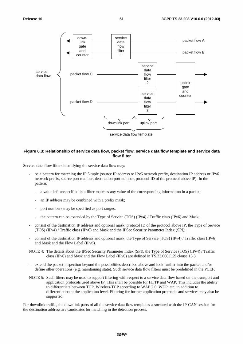
3GPP
3GPP TS 23.203 V10.6.0 (2012-03) 51Release 10
service data flow template
downlink part uplink part
servicedataflowfilter
1
packet flow A
packet flow B
packet flow Cservicedata flow
servicedataflowfilter
2
packet flow D
servicedataflowfilter
3
down-linkgateand
counter
uplinkgateand
counter
Figure 6.3: Relationship of service data flow, packet flow, service data flow template and service data flow filter
Service data flow filters identifying the service data flow may:
- be a pattern for matching the IP 5 tuple (source IP address or IPv6 network prefix, destination IP address or IPv6 network prefix, source port number, destination port number, protocol ID of the protocol above IP). In the pattern:
- a value left unspecified in a filter matches any value of the corresponding information in a packet;
- an IP address may be combined with a prefix mask;
- port numbers may be specified as port ranges.
- the pattern can be extended by the Type of Service (TOS) (IPv4) / Traffic class (IPv6) and Mask;
- consist of the destination IP address and optional mask, protocol ID of the protocol above IP, the Type of Service (TOS) (IPv4) / Traffic class (IPv6) and Mask and the IPSec Security Parameter Index (SPI);
- consist of the destination IP address and optional mask, the Type of Service (TOS) (IPv4) / Traffic class (IPv6) and Mask and the Flow Label (IPv6).
NOTE 4: The details about the IPSec Security Parameter Index (SPI), the Type of Service (TOS) (IPv4) / Traffic class (IPv6) and Mask and the Flow Label (IPv6) are defined in TS 23.060 [12] clause 15.3.
- extend the packet inspection beyond the possibilities described above and look further into the packet and/or define other operations (e.g. maintaining state). Such service data flow filters must be predefined in the PCEF.
NOTE 5: Such filters may be used to support filtering with respect to a service data flow based on the transport and application protocols used above IP. This shall be possible for HTTP and WAP. This includes the ability to differentiate between TCP, Wireless-TCP according to WAP 2.0, WDP, etc, in addition to differentiation at the application level. Filtering for further application protocols and services may also be supported.
For downlink traffic, the downlink parts of all the service data flow templates associated with the IP-CAN session for the destination address are candidates for matching in the detection process.
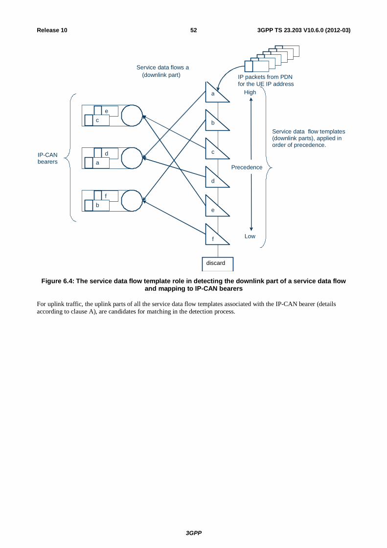
3GPP
3GPP TS 23.203 V10.6.0 (2012-03) 52Release 10
Service data flows a (downlink part)
High
Low
Precedence
IP packets from PDN for the UE IP address
Service data flow templates (downlink parts), applied in order of precedence.
e
c
d
a
f b
a
b
c
d
e
f
IP-CAN bearers
discard
Figure 6.4: The service data flow template role in detecting the downlink part of a service data flow and mapping to IP-CAN bearers
For uplink traffic, the uplink parts of all the service data flow templates associated with the IP-CAN bearer (details according to clause A), are candidates for matching in the detection process.
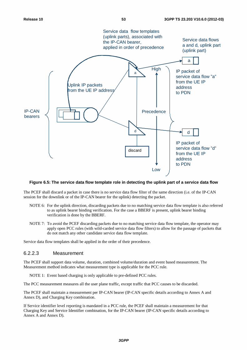
3GPP
3GPP TS 23.203 V10.6.0 (2012-03) 53Release 10
a
d
Service data flowsa and d, uplink part(uplink part)
High
Low
Precedence
Uplink IP packets from the UE IP address
Service data flow templates (uplink parts), associated with the IP-CAN bearer, applied in order of precedence
d
IP-CAN bearers
a
IP packet of service data flow ”a” from the UE IP address to PDN
IP packet of service data flow ”d” from the UE IP address to PDN
discard
Figure 6.5: The service data flow template role in detecting the uplink part of a service data flow
The PCEF shall discard a packet in case there is no service data flow filter of the same direction (i.e. of the IP-CAN session for the downlink or of the IP-CAN bearer for the uplink) detecting the packet.
NOTE 6: For the uplink direction, discarding packets due to no matching service data flow template is also referred to as uplink bearer binding verification. For the case a BBERF is present, uplink bearer binding verification is done by the BBERF.
NOTE 7: To avoid the PCEF discarding packets due to no matching service data flow template, the operator may apply open PCC rules (with wild-carded service data flow filters) to allow for the passage of packets that do not match any other candidate service data flow template.
Service data flow templates shall be applied in the order of their precedence.
6.2.2.3 Measurement
The PCEF shall support data volume, duration, combined volume/duration and event based measurement. The Measurement method indicates what measurement type is applicable for the PCC rule.
NOTE 1: Event based charging is only applicable to pre-defined PCC rules.
The PCC measurement measures all the user plane traffic, except traffic that PCC causes to be discarded.
The PCEF shall maintain a measurement per IP-CAN bearer (IP-CAN specific details according to Annex A and Annex D), and Charging Key combination.
If Service identifier level reporting is mandated in a PCC rule, the PCEF shall maintain a measurement for that Charging Key and Service Identifier combination, for the IP-CAN bearer (IP-CAN specific details according to Annex A and Annex D).
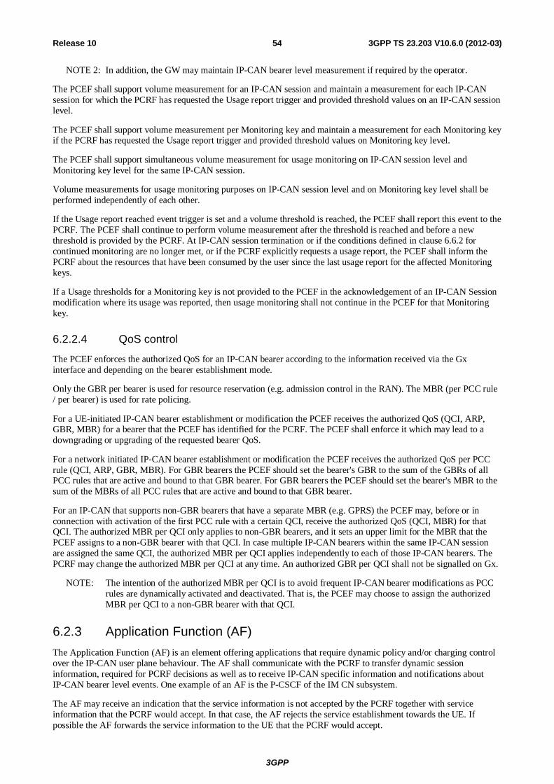
3GPP
3GPP TS 23.203 V10.6.0 (2012-03) 54Release 10
NOTE 2: In addition, the GW may maintain IP-CAN bearer level measurement if required by the operator.
The PCEF shall support volume measurement for an IP-CAN session and maintain a measurement for each IP-CAN session for which the PCRF has requested the Usage report trigger and provided threshold values on an IP-CAN session level.
The PCEF shall support volume measurement per Monitoring key and maintain a measurement for each Monitoring key if the PCRF has requested the Usage report trigger and provided threshold values on Monitoring key level.
The PCEF shall support simultaneous volume measurement for usage monitoring on IP-CAN session level and Monitoring key level for the same IP-CAN session.
Volume measurements for usage monitoring purposes on IP-CAN session level and on Monitoring key level shall be performed independently of each other.
If the Usage report reached event trigger is set and a volume threshold is reached, the PCEF shall report this event to the PCRF. The PCEF shall continue to perform volume measurement after the threshold is reached and before a new threshold is provided by the PCRF. At IP-CAN session termination or if the conditions defined in clause 6.6.2 for continued monitoring are no longer met, or if the PCRF explicitly requests a usage report, the PCEF shall inform the PCRF about the resources that have been consumed by the user since the last usage report for the affected Monitoring keys.
If a Usage thresholds for a Monitoring key is not provided to the PCEF in the acknowledgement of an IP-CAN Session modification where its usage was reported, then usage monitoring shall not continue in the PCEF for that Monitoring key.
6.2.2.4 QoS control
The PCEF enforces the authorized QoS for an IP-CAN bearer according to the information received via the Gx interface and depending on the bearer establishment mode.
Only the GBR per bearer is used for resource reservation (e.g. admission control in the RAN). The MBR (per PCC rule / per bearer) is used for rate policing.
For a UE-initiated IP-CAN bearer establishment or modification the PCEF receives the authorized QoS (QCI, ARP, GBR, MBR) for a bearer that the PCEF has identified for the PCRF. The PCEF shall enforce it which may lead to a downgrading or upgrading of the requested bearer QoS.
For a network initiated IP-CAN bearer establishment or modification the PCEF receives the authorized QoS per PCC rule (QCI, ARP, GBR, MBR). For GBR bearers the PCEF should set the bearer's GBR to the sum of the GBRs of all PCC rules that are active and bound to that GBR bearer. For GBR bearers the PCEF should set the bearer's MBR to the sum of the MBRs of all PCC rules that are active and bound to that GBR bearer.
For an IP-CAN that supports non-GBR bearers that have a separate MBR (e.g. GPRS) the PCEF may, before or in connection with activation of the first PCC rule with a certain QCI, receive the authorized QoS (QCI, MBR) for that QCI. The authorized MBR per QCI only applies to non-GBR bearers, and it sets an upper limit for the MBR that the PCEF assigns to a non-GBR bearer with that QCI. In case multiple IP-CAN bearers within the same IP-CAN session are assigned the same QCI, the authorized MBR per QCI applies independently to each of those IP-CAN bearers. The PCRF may change the authorized MBR per QCI at any time. An authorized GBR per QCI shall not be signalled on Gx.
NOTE: The intention of the authorized MBR per QCI is to avoid frequent IP-CAN bearer modifications as PCC rules are dynamically activated and deactivated. That is, the PCEF may choose to assign the authorized MBR per QCI to a non-GBR bearer with that QCI.
6.2.3 Application Function (AF) The Application Function (AF) is an element offering applications that require dynamic policy and/or charging control over the IP-CAN user plane behaviour. The AF shall communicate with the PCRF to transfer dynamic session information, required for PCRF decisions as well as to receive IP-CAN specific information and notifications about IP-CAN bearer level events. One example of an AF is the P-CSCF of the IM CN subsystem.
The AF may receive an indication that the service information is not accepted by the PCRF together with service information that the PCRF would accept. In that case, the AF rejects the service establishment towards the UE. If possible the AF forwards the service information to the UE that the PCRF would accept.
3GPP
3GPP TS 23.203 V10.6.0 (2012-03) 55Release 10
An AF may communicate with multiple PCRFs. The AF shall contact the appropriate PCRF based on either:
- the end user IP Address; and/or
- a UE identity that the AF is aware of.
NOTE 1: By using the end user IP address, an AF is not required to acquire any UE identity in order to provide information, for a specific user, to the PCRF.
In case of private IP address being used for the end user, the AF may send additional PDN information (e.g. PDN ID) over the Rx interface. This PDN information is used by the PCRF for session binding, and it is also used to help selecting the correct PCRF.
For certain events related to policy control, the AF shall be able to give instructions to the PCRF to act on its own, i.e. based on the service information currently available as described in clause 6.1.5.
The AF may use the IP-CAN bearer level information in the AF session signalling or to adjust the IP-CAN bearer level event reporting.
The AF may request the PCRF to report on IP-CAN bearer level events (e.g. the signalling path status for the AF session). The AF shall cancel the request when the AF ceases handling the user.
NOTE 2: The QoS authorization based on incomplete service information is required for e.g. IMS session setup scenarios with available resources on originating side and a need for resource reservation on terminating side.
The AF may request the PCRF to report on the change of type of IP-CAN. In the case of 3GPP IP-CAN, the information of the Radio Access Technology Type (e.g. UTRAN) and the change thereof shall be also reported to the AF, even if the IP-CAN type is unchanged.
NOTE 3: The H-PCRF informs the AF of event triggers that cannot be reported. For detail see Annex L.
To support sponsored data connectivity (see Annex N), the AF may provide the PCRF with the sponsored data connectivity information, including optionally a usage threshold, as specified in clause 5.2.1. The AF may request the PCRF to report events related to sponsored data connectivity.
If the user plane traffic traverses the AF, the AF may handle the usage monitoring and therefore it is not required to provide a usage threshold to the PCRF as part of the sponsored data connectivity information.
6.2.4 Subscription Profile Repository (SPR) The SPR logical entity contains all subscriber/subscription related information needed for subscription-based policies and IP-CAN bearer level PCC rules by the PCRF. The SPR may be combined with or distributed across other databases in the operator's network, but those functional elements and their requirements for the SPR are out of scope of this document.
NOTE 1: The SPR's relation to existing subscriber databases is not specified in this Release.
The SPR may provide the following subscription profile information (per PDN, which is identified by the PDN identifier):
- Subscriber's allowed services;
- For each allowed service, a pre-emption priority;
- Information on subscriber's allowed QoS, including the Subscribed Guaranteed Bandwidth QoS;
- Subscriber's charging related information (e.g. location information relevant for charging);
- Subscriber's User CSG Information reporting rules;
- Subscriber category;
- Subscriber's usage monitoring related information;
- MPS EPS Priority and MPS Priority Level;
3GPP
3GPP TS 23.203 V10.6.0 (2012-03) 56Release 10
- IMS Signalling Priority.
The SPR may provide the following sponsored data connectivity profile information:
- A list of Application Service Providers and their applications per sponsor identity.
NOTE 2: The sponsored data connectivity profile may be locally configured at the PCRF.
If the IMS Signalling Priority is set, it indicates that the IMS Signalling Bearer and the Default Bearer are assigned ARP appropriate for MPS at the time of the establishment of the PDN connection for IMS, i.e. EPS Attach or PDN Connectivity Request.
6.2.5 Online Charging System The Online Charging System (OCS) performs online credit control functions as specified in TS 32.240 [3].
The OCS may trigger the PCEF to initiate a IP-CAN bearer service termination at any point in time.
NOTE: As the OCS performs the credit control per charging key basis (and thus has not necessarily the knowledge about the existence of any specific service data flow), it is recommended to use different charging keys for any service data flows that shall not be unintentionally interrupted.
There may be several OCSs in a PLMN. The default OCS addresses (i.e. the primary address and secondary address) shall be locally pre-configured within the PCEF. OCS addresses may also be passed once per IP-CAN session from the PCRF to the PCEF. The OCS addresses provided by the PCRF shall have a higher priority than the pre-configured ones.
6.2.6 Offline Charging System (OFCS) The Offline Charging System is specified in TS 32.240 [3].
There may be several OFCSs in a PLMN. The default OFCS addresses (i.e. the primary address and secondary address) shall be locally pre-configured within the PCEF. OFCS addresses may also be passed once per IP-CAN session from the PCRF to the PCEF. The addresses provided by the PCRF shall have a higher priority than the pre-configured ones.
6.2.7 Bearer Binding and Event Reporting Function (BBERF)
6.2.7.1 General
The BBERF includes the following functionalities:
- Bearer binding.
- Uplink bearer binding verification.
- Event reporting to the PCRF.
- Sending or receiving IP-CAN-specific parameters, to or from the PCRF.
6.2.7.2 Service data flow detection
The service data flow detection at the BBERF is identical to the detection at PCEF with the following modifications:
- If the service data flow is tunnelled at the BBERF, the BBERF uses information on the mobility protocol tunnelling header provided by the PCRF and the QoS rules to detect the service data flows.
For the uplink direction, the BBERF applies QoS rules with a bearer binding to the bearer that the packet arrived on. The uplink bearer binding verification is successful if there is a QoS rule with a matching uplink SDF filter. The BBERF shall discard packets for which the uplink bearer binding verification fails.
6.2.7.3 QoS Control
The ARP, GBR, MBR and QCI are used by the BBERF in the same way as in the PCEF for resource reservation.
3GPP
3GPP TS 23.203 V10.6.0 (2012-03) 57Release 10
When access network is not utilizing QCI based QoS parameters, the BBERF shall be able to convert a QoS class identifier value to QoS attribute values used in the access network and determine the QoS class identifier value from a set of QoS attribute values used in the access network.
NOTE: The definition of the mapping between QCI and Non 3GPP access specific QoS is outside of scope for 3GPP.
The BBERF controls the QoS that is provided to a combined set of service data flows. BBERF ensures that the resources which can be used by an authorized set of service data flows are within the "authorized resources" specified via the Gxx interface by "authorized QoS". The authorized QoS provides an upper bound on the resources that can be reserved (GBR) or allocated (MBR) for the service data flows.
In order to support the different IP-CAN bearer establishment modes (UE-only or UE/NW), the BBERF shall support the same procedures for handling different IP-CAN bearer establishment modes as specified for the PCEF in clause 6.2.2.1.
6.2.8 User Data Repository (UDR) The UDR is a functional entity that acts as a single logical repository storing user data. As such it may contain all subscriber/subscription related information needed by the PCRF. In deployment scenarios where the UDR is used it replaces the SPR. The UDR provides a unique reference point to fetch these subscriber/subscription data. This reference point is named Ud. More information on the UDR can be found in TS 23.335 [25].
The SPR data listed in clause 6.2.4 are stored in the UDR, the information model remains unspecified.
6.3 Policy and charging control rule
6.3.1 General The Policy and charging control rule (PCC rule) comprises the information that is required to enable the user plane detection of, the policy control and proper charging for a service data flow. The packets detected by applying the service data flow template of a PCC rule are designated a service data flow.
Two different types of PCC rules exist: Dynamic rules and predefined rules. The dynamic PCC rules are provisioned by the PCRF via the Gx reference point, while the predefined PCC rules are directly provisioned into the PCEF and only referenced by the PCRF. The usage of pre-defined PCC rules for QoS control is possible if the BBF remains in the PCEF during the lifetime of an IP-CAN session. In addition, pre-defined PCC rules may be used in a non-roaming situation and if it can be guaranteed that corresponding pre-defined QoS rules are configured in the BBF and activated along with the pre-defined PCC rules.
NOTE 1: The procedure for provisioning predefined PCC rules is out of scope for this TS.
NOTE 2: There may be another type of predefined rules that are not explicitly known in the PCRF and not under the control of the PCRF. The operator may define such predefined PCC rules, to be activated by the PCEF on one IP-CAN bearer within the IP-CAN session. The PCEF may only activate such predefined PCC rules if there is no UE provided traffic mapping information related to that IP-CAN bearer. The IP-CAN session termination procedure deactivates such predefined PCC rules.
There are defined procedures for activation, modification and deactivation of PCC rules (as described in clause 6.3.2). The PCRF may activate, modify and deactivate a PCC rule at any time, over the Gx reference point. However, the modification procedure is applicable to dynamic PCC rules only.
Each PCC rule shall be installed for a single IP-CAN bearer only, i.e. PCC rules containing completely identical information shall receive different PCC rule identifiers (an exception are predefined PCC rules that contain only uplink service data flow filters and which are known to the PCRF, see clause 6.3.2).
The operator defines the PCC rules.
Table 6.3 lists the information contained in a PCC rule, including the information name, the description and whether the PCRF may modify this information in a dynamic PCC rule which is active in the PCEF. The Category field indicates if a certain piece of information is mandatory or not for the construction of a PCC rule, i.e. if it is possible to construct a PCC rule without it.
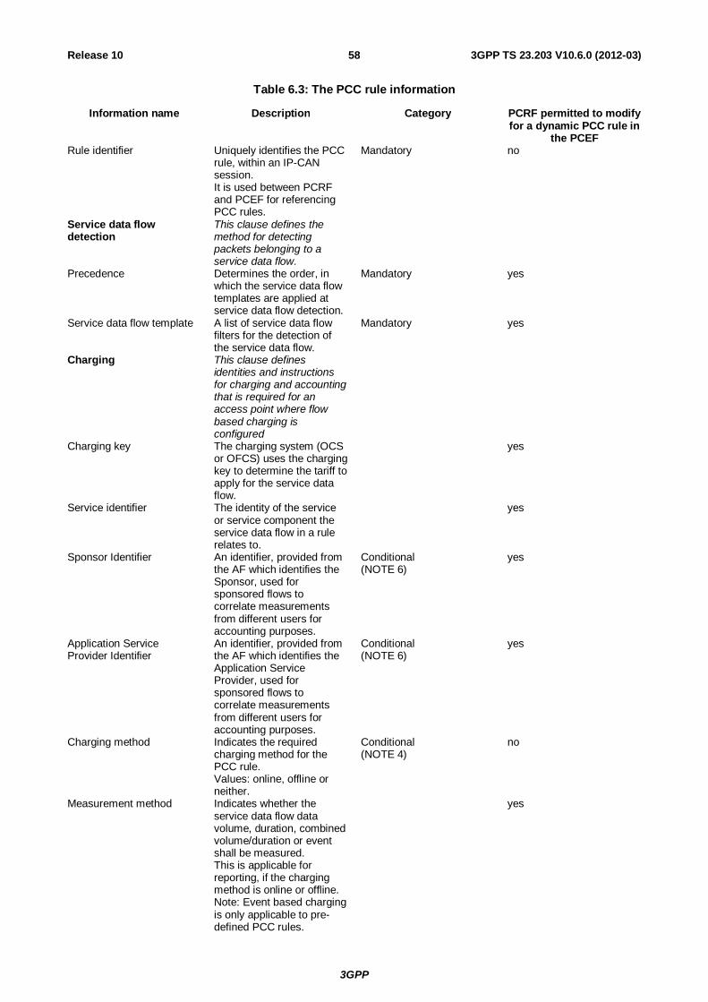
3GPP
3GPP TS 23.203 V10.6.0 (2012-03) 58Release 10
Table 6.3: The PCC rule information
Information name Description Category PCRF permitted to modify for a dynamic PCC rule in
the PCEF Rule identifier Uniquely identifies the PCC
rule, within an IP-CAN session. It is used between PCRF and PCEF for referencing PCC rules.
Mandatory no
Service data flow detection
This clause defines the method for detecting packets belonging to a service data flow.
Precedence Determines the order, in which the service data flow templates are applied at service data flow detection.
Mandatory yes
Service data flow template A list of service data flow filters for the detection of the service data flow.
Mandatory yes
Charging This clause defines identities and instructions for charging and accounting that is required for an access point where flow based charging is configured
Charging key The charging system (OCS or OFCS) uses the charging key to determine the tariff to apply for the service data flow.
yes
Service identifier The identity of the service or service component the service data flow in a rule relates to.
yes
Sponsor Identifier An identifier, provided from the AF which identifies the Sponsor, used for sponsored flows to correlate measurements from different users for accounting purposes.
Conditional (NOTE 6)
yes
Application Service Provider Identifier
An identifier, provided from the AF which identifies the Application Service Provider, used for sponsored flows to correlate measurements from different users for accounting purposes.
Conditional (NOTE 6)
yes
Charging method Indicates the required charging method for the PCC rule. Values: online, offline or neither.
Conditional (NOTE 4)
no
Measurement method Indicates whether the service data flow data volume, duration, combined volume/duration or event shall be measured. This is applicable for reporting, if the charging method is online or offline. Note: Event based charging is only applicable to pre-defined PCC rules.
yes
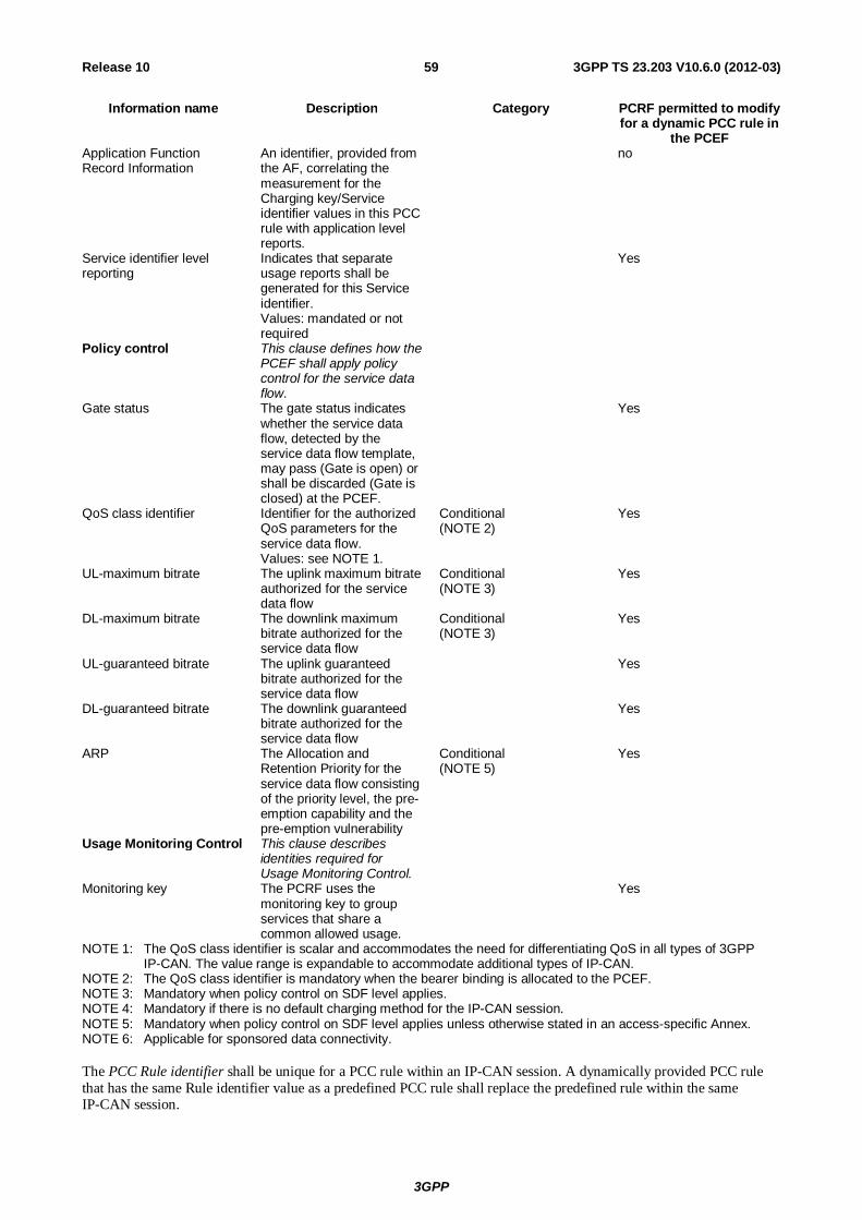
3GPP
3GPP TS 23.203 V10.6.0 (2012-03) 59Release 10
Information name Description Category PCRF permitted to modify for a dynamic PCC rule in
the PCEF Application Function Record Information
An identifier, provided from the AF, correlating the measurement for the Charging key/Service identifier values in this PCC rule with application level reports.
no
Service identifier level reporting
Indicates that separate usage reports shall be generated for this Service identifier. Values: mandated or not required
Yes
Policy control This clause defines how the PCEF shall apply policy control for the service data flow.
Gate status The gate status indicates whether the service data flow, detected by the service data flow template, may pass (Gate is open) or shall be discarded (Gate is closed) at the PCEF.
Yes
QoS class identifier Identifier for the authorized QoS parameters for the service data flow. Values: see NOTE 1.
Conditional (NOTE 2)
Yes
UL-maximum bitrate The uplink maximum bitrate authorized for the service data flow
Conditional (NOTE 3)
Yes
DL-maximum bitrate The downlink maximum bitrate authorized for the service data flow
Conditional (NOTE 3)
Yes
UL-guaranteed bitrate The uplink guaranteed bitrate authorized for the service data flow
Yes
DL-guaranteed bitrate The downlink guaranteed bitrate authorized for the service data flow
Yes
ARP The Allocation and Retention Priority for the service data flow consisting of the priority level, the pre-emption capability and the pre-emption vulnerability
Conditional (NOTE 5)
Yes
Usage Monitoring Control This clause describes identities required for Usage Monitoring Control.
Monitoring key The PCRF uses the monitoring key to group services that share a common allowed usage.
Yes
NOTE 1: The QoS class identifier is scalar and accommodates the need for differentiating QoS in all types of 3GPP IP-CAN. The value range is expandable to accommodate additional types of IP-CAN.
NOTE 2: The QoS class identifier is mandatory when the bearer binding is allocated to the PCEF. NOTE 3: Mandatory when policy control on SDF level applies. NOTE 4: Mandatory if there is no default charging method for the IP-CAN session. NOTE 5: Mandatory when policy control on SDF level applies unless otherwise stated in an access-specific Annex. NOTE 6: Applicable for sponsored data connectivity. The PCC Rule identifier shall be unique for a PCC rule within an IP-CAN session. A dynamically provided PCC rule that has the same Rule identifier value as a predefined PCC rule shall replace the predefined rule within the same IP-CAN session.
3GPP
3GPP TS 23.203 V10.6.0 (2012-03) 60Release 10
The PCC Service data flow template may comprise any number of Service data flow filters. A Service data flow filter contains information for matching user plane packets. A Service data flow filter, provided from the PCRF, contains information elements as described in clause 6.2.2.2. The Service data flow template filtering information within an activated PCC rule is applied at the PCEF to identify the packets belonging to a particular service data flow.
NOTE 3: Predefined PCC rules may include service data flow filters, which support extended capabilities, including enhanced capabilities to identify events associated with application protocols.
The PCC Precedence defines in what order the activated PCC rules within the same IP-CAN session shall be applied at the PCEF for service data flow detection. When a dynamic PCC rule and a predefined PCC rule have the same precedence, the dynamic PCC rule takes precedence.
NOTE 4: The operator shall ensure that overlap between the predefined PCC rules can be resolved based on precedence of each predefined PCC rule in the PCEF. The PCRF shall ensure that overlap between the dynamically allocated PCC rules can be resolved based on precedence of each dynamically allocated PCC rule. Further information about the configuration of the PCC rule precedence is described in Annex G.
For downlink packets all the service data flow templates, activated for the IP-CAN session shall be applied for service data flow detection and for the mapping to the correct IP-CAN bearer. For uplink packets the service data flow templates activated on their IP-CAN bearer shall be applied for service data flow detection.
The PCC Charging key is the reference to the tariff for the service data flow. Any number of PCC Rules may share the same charging key value. The charging key values for each service shall be operator configurable.
NOTE 5: Assigning the same Charging key for several service data flows implies that the charging does not require the credit management to be handled separately.
NOTE 6: If the IP flow mobility is supported and the tariff depends on what access network is in use for the service data flow, then a separate Charging key can be allocated for each access network, and the PCRF can set the Charging key in accordance with the access network in use.
The PCC Service identifier identifies the service. PCC Rules may share the same service identifier value. The service identifier provides the most detailed identification, specified for flow based charging, of a service data flow.
NOTE 7: The PCC service identifier need not have any relationship to service identifiers used on the AF level, i.e. is an operator policy option.
The Sponsor Identifier indicates the (3rd) party organization willing to pay for the operator's charge for connectivity required to deliver a service to the end user.
The Application Service Provider Identifier indicates the (3rd) party organization delivering a service to the end user.
The PCC Charging method indicates whether online charging, offline charging, or both are required or the service data flow is not subject to any end user charging. If the PCC charging method identifies that the service data flow is not subject to any end user charging, a PCC Charging key shall not be included in the PCC rule for that service data flow, along with other charging related parameters. If the PCC charging method is omitted the PCEF shall apply the default charging method as determined at IP-CAN session establishment (see clause 6.4). The PCC Charging method is mandatory if there is no default charging method for the IP-CAN session.
The PCC Measurement method indicates what measurements apply for charging for PCC rule.
The PCC Service Identifier Level Reporting indicates whether the PCEF shall generate reports per Service Identifier. The PCEF shall accumulate the measurements from all PCC rules with the same combination of Charging key/Service identifier values in a single report.
The PCC Application function record information identifies an instance of service usage. A subsequently generated usage report, generated as a result of the PCC rule, may include the Application function record information, if available. The Application Function Record Information may contain the AF Charging Identifier and/or the Flow identifiers. The report is however not restricted to include only usage related to the Application function record information reported, as the report accumulates the usage for all PCC rules with the same combination of Charging key/Service identifier values. If exclusive charging information related to the Application function record information is required, the PCRF shall provide a service identifier, not used by any other PCC rule of the IP-CAN session at this point in time, for the AF session.
3GPP
3GPP TS 23.203 V10.6.0 (2012-03) 61Release 10
NOTE 8: For example, the PCRF may be configured to maintain a range of service identifier values for each service which require exclusive per instance charging information. Whenever a separate counting or credit management for an AF session is required, the PCRF shall select a value, which is not used at this point in time, within that range. The uniqueness of the service identifier in the PCEF ensures a separate accounting/credit management while the AF record information identifies the instance of the service.
The PCC Gate indicates whether the PCEF shall let a packet matching the PCC Service data flow template, pass through (gate is open) the PCEF or the PCEF shall discard (gate is closed) the packet.
NOTE 9: A packet, matching a PCC Rule with an open gate, may be discarded due to credit management reasons.
The QoS Class Identifier for the service data flow. The QoS class identifier represents the QoS parameters for the service data flow. The PCEF maintains the mapping between QoS class identifier and the QoS concept applied within the specific IP-CAN. The bitrate information is separate from the QoS class identifier value.
The bitrates indicate the authorized bitrates at the IP packet level of the SDF, i.e. the bitrates of the IP packets before any IP-CAN specific compression or encapsulation.
The UL maximum-bitrate indicates the authorized maximum bitrate for the uplink component of the service data flow.
The DL maximum-bitrate indicates the authorized maximum bitrate for the downlink component of the service data flow.
The UL guaranteed-bitrate indicates the authorized guaranteed bitrate for the uplink component of the service data flow.
The DL guaranteed-bitrate indicates the authorized guaranteed bitrate for the downlink component of the service data flow.
The 'Maximum bitrate' is used for enforcement of the maximum bit rate that the SDF may consume, while the 'Guaranteed bitrate' is used by the PCEF to determine resource allocation.
The Allocation/Retention Priority indicates the priority of allocation and retention of the service data flow. The ARP contains information about the priority level, the pre-emption capability and the pre-emption vulnerability. The Allocation/Retention Priority resolves conflicts of demands for network resources.
The Monitoring Key is the reference to a resource threshold. Any number of PCC Rules may share the same monitoring key value. The monitoring key values for each service shall be operator configurable.
6.3.2 Policy and charging control rule operations Policy and charging control rule operations consist of activation, modification and de-activation of PCC rules.
Activation of a dynamic PCC rule provides the PCC rule information to the PCEF via the Gx reference point.
Activation of a predefined PCC rule provides an identifier of the relevant PCC rule to the PCEF via the Gx reference point.
Activation of a predefined PCC rule, not known in the PCRF, may be done by the PCEF based on operator policy. The PCEF may only activate such predefined PCC rule if there are no UE provided traffic mapping information related to the IP-CAN bearer. Further restrictions regarding the usage of pre-defined PCC rules are described in clause 6.3.1.
An active PCC rule means that:
- the service data flow template shall be used for service data flow detection;
- the service data flow template shall be used for mapping of downlink packets to the IP-CAN bearer determined by the bearer binding;
- the service data flow template shall be used for service data flow detection of uplink packets on the IP-CAN bearer determined by the bearer binding;
- usage data for the service data flow shall be recorded(further details can be found in clause 6.1.2 Reporting and clause 6.1.3 Credit Management);
- policies associated with the PCC rule, if any, shall be invoked.
3GPP
3GPP TS 23.203 V10.6.0 (2012-03) 62Release 10
A predefined PCC rule is known at least, within the scope of one access point.
NOTE 1: The same predefined PCC rule can be activated for multiple IP-CAN bearers in multiple IP-CAN sessions.
A predefined PCC rule that contains downlink service data flow filters can only be activated once per IP-CAN session. A predefined PCC rule that contains only uplink service data flow filters can be activated for multiple IP-CAN bearers of the same IP-CAN session (deactivation of such a predefined PCC rule would remove this PCC rule from every IP-CAN bearer).
The PCRF may, at any time, modify an active, dynamic PCC rule.
The PCRF may, at any time, deactivate an active PCC rule in the PCEF via the Gx reference point. At IP-CAN bearer termination all active PCC rules on that bearer are deactivated without explicit instructions from the PCRF to do so.
Policy and charging control rule operations can be also performed in a deferred mode. A PCC Rule may have either a single deferred activation time, or a single deferred deactivation time or both.
A PCC rule with only a deferred activation time shall be inactive until that time. A PCC rule with only a deferred deactivation time shall be active until that time. When the rule activation time occurs prior to the rule deactivation time, the rule is inactive until the activation and remains active until the deactivation time occurs. When the rule deactivation time occurs prior to the rule activation time, the rule is initially active until the deactivation time, then remains inactive until the activation time, and then becomes active again. An inactive PCC rule, that has not been activated yet, is still considered to be installed, and may be removed by the PCRF.
The PCRF shall always provide complete PCC rules when the deferred mode is used.
The PCRF may modify a currently installed PCC rule, including setting, modifying or clearing its deferred activation and/or deactivation time.
Deferred activation and deactivation of PCC rules can only be used for PCC rules that belong to the IP-CAN bearer without traffic mapping information.
NOTE 2: This limitation prevents dependencies on the signalling of changed traffic mapping information towards the UE.
Deferred modification of PCC rules shall not be applied for changes of the QoS or service data flow filter information of PCC rules.
6.4 IP-CAN bearer and IP-CAN session related policy information
The purpose of the IP-CAN bearer and IP-CAN session related policy information is to provide policy and charging control related information that is applicable to a single IP-CAN bearer or the whole IP-CAN session respectively. The PCRF provides the IP-CAN bearer and IP-CAN session related policy information to the PCEF and BBERF (if applicable) using the PCC rule and QoS rule (if applicable) provision procedure. The IP-CAN bearer related policy information may be provided together with rules or separately.
Table 6.4 lists the PCC related IP-CAN bearer and IP-CAN session related policy information.
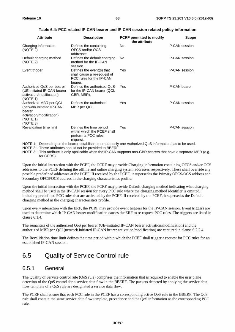
3GPP
3GPP TS 23.203 V10.6.0 (2012-03) 63Release 10
Table 6.4: PCC related IP-CAN bearer and IP-CAN session related policy information
Attribute Description PCRF permitted to modify the attribute
Scope
Charging information (NOTE 2)
Defines the containing OFCS and/or OCS addresses.
No IP-CAN session
Default charging method (NOTE 2)
Defines the default charging method for the IP-CAN session.
No IP-CAN session
Event trigger Defines the event(s) that shall cause a re-request of PCC rules for the IP-CAN bearer.
Yes IP-CAN session
Authorized QoS per bearer (UE-initiated IP-CAN bearer activation/modification) (NOTE 1)
Defines the authorised QoS for the IP-CAN bearer (QCI, GBR, MBR).
Yes IP-CAN bearer
Authorized MBR per QCI (network initiated IP-CAN bearer activation/modification) (NOTE 1) (NOTE 3)
Defines the authorised MBR per QCI.
Yes IP-CAN session
Revalidation time limit Defines the time period within which the PCEF shall perform a PCC rules request.
Yes IP-CAN session
NOTE 1: Depending on the bearer establishment mode only one Authorized QoS information has to be used. NOTE 2: These attributes should not be provided to BBERF. NOTE 3: This attribute is only applicable when the IP-CAN supports non-GBR bearers that have a separate MBR (e.g.
for GPRS). Upon the initial interaction with the PCEF, the PCRF may provide Charging information containing OFCS and/or OCS addresses to the PCEF defining the offline and online charging system addresses respectively. These shall override any possible predefined addresses at the PCEF. If received by the PCEF, it supersedes the Primary OFCS/OCS address and Secondary OFCS/OCS address in the charging characteristics profile.
Upon the initial interaction with the PCEF, the PCRF may provide Default charging method indicating what charging method shall be used in the IP-CAN session for every PCC rule where the charging method identifier is omitted, including predefined PCC rules that are activated by the PCEF. If received by the PCEF, it supersedes the Default charging method in the charging characteristics profile.
Upon every interaction with the ERF, the PCRF may provide event triggers for the IP-CAN session. Event triggers are used to determine which IP-CAN bearer modification causes the ERF to re-request PCC rules. The triggers are listed in clause 6.1.4.
The semantics of the authorized QoS per bearer (UE-initiated IP-CAN bearer activation/modification) and the authorized MBR per QCI (network initiated IP-CAN bearer activation/modification) are captured in clause 6.2.2.4.
The Revalidation time limit defines the time period within which the PCEF shall trigger a request for PCC rules for an established IP-CAN session.
6.5 Quality of Service Control rule
6.5.1 General The Quality of Service control rule (QoS rule) comprises the information that is required to enable the user plane detection of the QoS control for a service data flow in the BBERF. The packets detected by applying the service data flow template of a QoS rule are designated a service data flow.
The PCRF shall ensure that each PCC rule in the PCEF has a corresponding active QoS rule in the BBERF. The QoS rule shall contain the same service data flow template, precedence and the QoS information as the corresponding PCC rule.
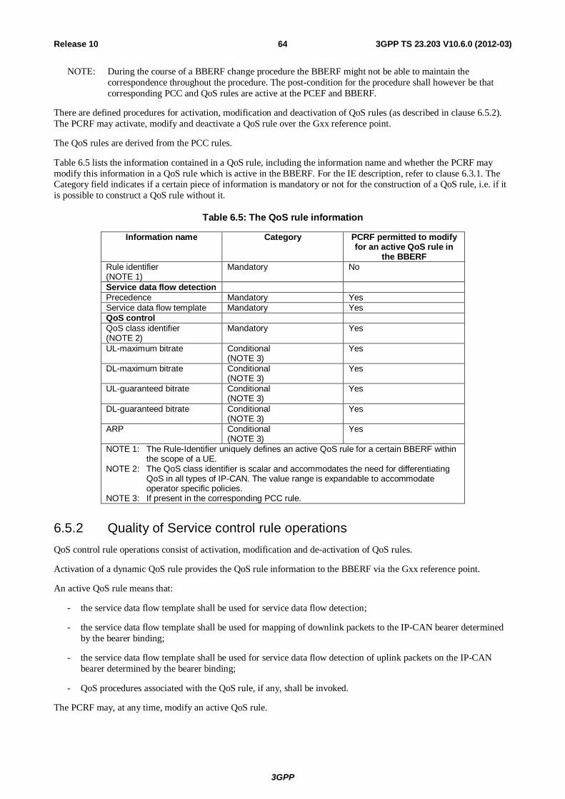
3GPP
3GPP TS 23.203 V10.6.0 (2012-03) 64Release 10
NOTE: During the course of a BBERF change procedure the BBERF might not be able to maintain the correspondence throughout the procedure. The post-condition for the procedure shall however be that corresponding PCC and QoS rules are active at the PCEF and BBERF.
There are defined procedures for activation, modification and deactivation of QoS rules (as described in clause 6.5.2). The PCRF may activate, modify and deactivate a QoS rule over the Gxx reference point.
The QoS rules are derived from the PCC rules.
Table 6.5 lists the information contained in a QoS rule, including the information name and whether the PCRF may modify this information in a QoS rule which is active in the BBERF. For the IE description, refer to clause 6.3.1. The Category field indicates if a certain piece of information is mandatory or not for the construction of a QoS rule, i.e. if it is possible to construct a QoS rule without it.
Table 6.5: The QoS rule information
Information name Category PCRF permitted to modify for an active QoS rule in
the BBERF Rule identifier (NOTE 1)
Mandatory No
Service data flow detection Precedence Mandatory Yes Service data flow template Mandatory Yes QoS control QoS class identifier (NOTE 2)
Mandatory Yes
UL-maximum bitrate Conditional (NOTE 3)
Yes
DL-maximum bitrate Conditional (NOTE 3)
Yes
UL-guaranteed bitrate Conditional (NOTE 3)
Yes
DL-guaranteed bitrate Conditional (NOTE 3)
Yes
ARP Conditional (NOTE 3)
Yes
NOTE 1: The Rule-Identifier uniquely defines an active QoS rule for a certain BBERF within the scope of a UE.
NOTE 2: The QoS class identifier is scalar and accommodates the need for differentiating QoS in all types of IP-CAN. The value range is expandable to accommodate operator specific policies.
NOTE 3: If present in the corresponding PCC rule.
6.5.2 Quality of Service control rule operations QoS control rule operations consist of activation, modification and de-activation of QoS rules.
Activation of a dynamic QoS rule provides the QoS rule information to the BBERF via the Gxx reference point.
An active QoS rule means that:
- the service data flow template shall be used for service data flow detection;
- the service data flow template shall be used for mapping of downlink packets to the IP-CAN bearer determined by the bearer binding;
- the service data flow template shall be used for service data flow detection of uplink packets on the IP-CAN bearer determined by the bearer binding;
- QoS procedures associated with the QoS rule, if any, shall be invoked.
The PCRF may, at any time, modify an active QoS rule.
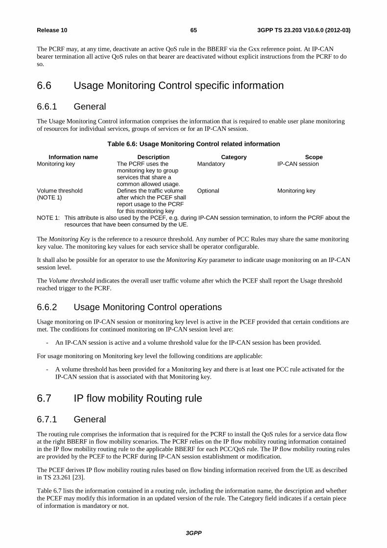
3GPP
3GPP TS 23.203 V10.6.0 (2012-03) 65Release 10
The PCRF may, at any time, deactivate an active QoS rule in the BBERF via the Gxx reference point. At IP-CAN bearer termination all active QoS rules on that bearer are deactivated without explicit instructions from the PCRF to do so.
6.6 Usage Monitoring Control specific information
6.6.1 General The Usage Monitoring Control information comprises the information that is required to enable user plane monitoring of resources for individual services, groups of services or for an IP-CAN session.
Table 6.6: Usage Monitoring Control related information
Information name Description Category Scope Monitoring key The PCRF uses the
monitoring key to group services that share a common allowed usage.
Mandatory IP-CAN session
Volume threshold (NOTE 1)
Defines the traffic volume after which the PCEF shall report usage to the PCRF for this monitoring key
Optional Monitoring key
NOTE 1: This attribute is also used by the PCEF, e.g. during IP-CAN session termination, to inform the PCRF about the resources that have been consumed by the UE.
The Monitoring Key is the reference to a resource threshold. Any number of PCC Rules may share the same monitoring key value. The monitoring key values for each service shall be operator configurable.
It shall also be possible for an operator to use the Monitoring Key parameter to indicate usage monitoring on an IP-CAN session level.
The Volume threshold indicates the overall user traffic volume after which the PCEF shall report the Usage threshold reached trigger to the PCRF.
6.6.2 Usage Monitoring Control operations Usage monitoring on IP-CAN session or monitoring key level is active in the PCEF provided that certain conditions are met. The conditions for continued monitoring on IP-CAN session level are:
- An IP-CAN session is active and a volume threshold value for the IP-CAN session has been provided.
For usage monitoring on Monitoring key level the following conditions are applicable:
- A volume threshold has been provided for a Monitoring key and there is at least one PCC rule activated for the IP-CAN session that is associated with that Monitoring key.
6.7 IP flow mobility Routing rule
6.7.1 General The routing rule comprises the information that is required for the PCRF to install the QoS rules for a service data flow at the right BBERF in flow mobility scenarios. The PCRF relies on the IP flow mobility routing information contained in the IP flow mobility routing rule to the applicable BBERF for each PCC/QoS rule. The IP flow mobility routing rules are provided by the PCEF to the PCRF during IP-CAN session establishment or modification.
The PCEF derives IP flow mobility routing rules based on flow binding information received from the UE as described in TS 23.261 [23].
Table 6.7 lists the information contained in a routing rule, including the information name, the description and whether the PCEF may modify this information in an updated version of the rule. The Category field indicates if a certain piece of information is mandatory or not.
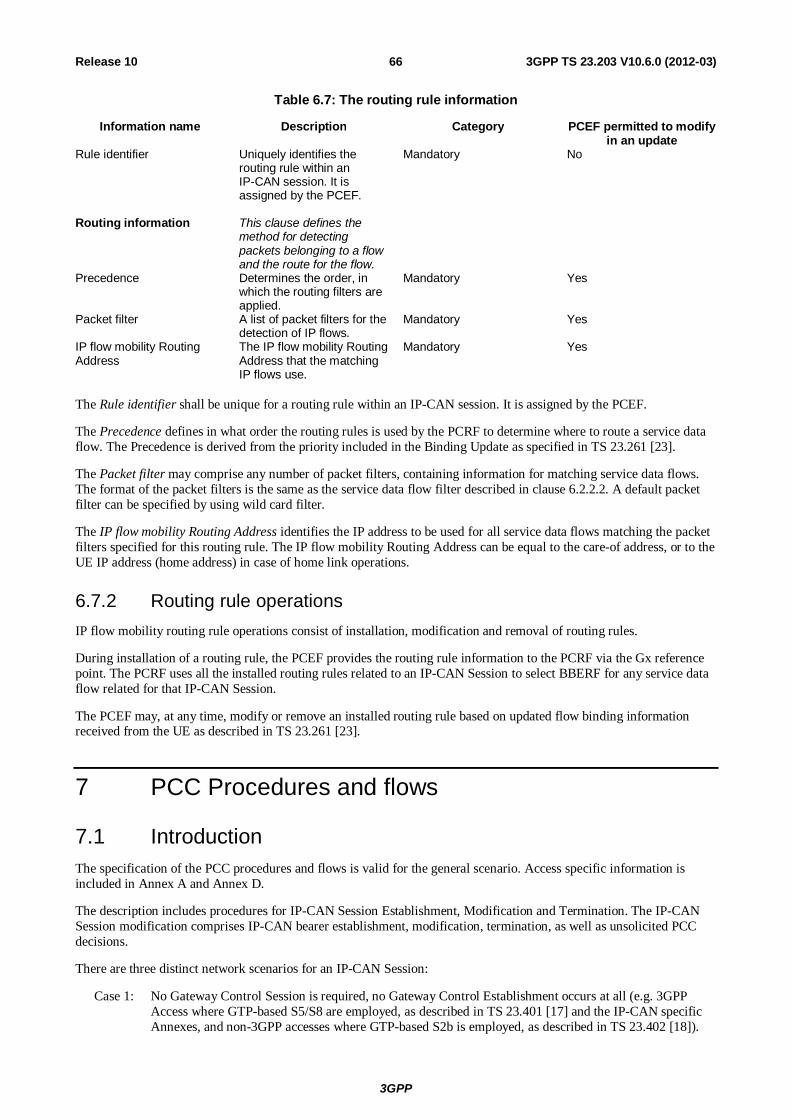
3GPP
3GPP TS 23.203 V10.6.0 (2012-03) 66Release 10
Table 6.7: The routing rule information
Information name Description Category PCEF permitted to modify in an update
Rule identifier Uniquely identifies the routing rule within an IP-CAN session. It is assigned by the PCEF.
Mandatory No
Routing information
This clause defines the method for detecting packets belonging to a flow and the route for the flow.
Precedence Determines the order, in which the routing filters are applied.
Mandatory Yes
Packet filter A list of packet filters for the detection of IP flows.
Mandatory Yes
IP flow mobility Routing Address
The IP flow mobility Routing Address that the matching IP flows use.
Mandatory Yes
The Rule identifier shall be unique for a routing rule within an IP-CAN session. It is assigned by the PCEF.
The Precedence defines in what order the routing rules is used by the PCRF to determine where to route a service data flow. The Precedence is derived from the priority included in the Binding Update as specified in TS 23.261 [23].
The Packet filter may comprise any number of packet filters, containing information for matching service data flows. The format of the packet filters is the same as the service data flow filter described in clause 6.2.2.2. A default packet filter can be specified by using wild card filter.
The IP flow mobility Routing Address identifies the IP address to be used for all service data flows matching the packet filters specified for this routing rule. The IP flow mobility Routing Address can be equal to the care-of address, or to the UE IP address (home address) in case of home link operations.
6.7.2 Routing rule operations IP flow mobility routing rule operations consist of installation, modification and removal of routing rules.
During installation of a routing rule, the PCEF provides the routing rule information to the PCRF via the Gx reference point. The PCRF uses all the installed routing rules related to an IP-CAN Session to select BBERF for any service data flow related for that IP-CAN Session.
The PCEF may, at any time, modify or remove an installed routing rule based on updated flow binding information received from the UE as described in TS 23.261 [23].
7 PCC Procedures and flows
7.1 Introduction The specification of the PCC procedures and flows is valid for the general scenario. Access specific information is included in Annex A and Annex D.
The description includes procedures for IP-CAN Session Establishment, Modification and Termination. The IP-CAN Session modification comprises IP-CAN bearer establishment, modification, termination, as well as unsolicited PCC decisions.
There are three distinct network scenarios for an IP-CAN Session:
Case 1: No Gateway Control Session is required, no Gateway Control Establishment occurs at all (e.g. 3GPP Access where GTP-based S5/S8 are employed, as described in TS 23.401 [17] and the IP-CAN specific Annexes, and non-3GPP accesses where GTP-based S2b is employed, as described in TS 23.402 [18]).
3GPP
3GPP TS 23.203 V10.6.0 (2012-03) 67Release 10
Case 2: A Gateway Control Session is required. The BBERF establishes a Gateway Control Session prior to any IP-CAN session establishment. There are two sub-cases:
2a) The UE acquires a care of address (CoA) that is used for the S2c reference point. The same Gateway Control session applies for all IP-CAN sessions using that CoA.
2b) A Gateway Control Session is required, as described in TS 23.402 [18] and the IP-CAN specific Annexes, Gateway Control Session Establishment, as defined in clause 7.7.1. Each IP-CAN session is handled in a separate Gateway Control Session.
The PCRF determines at Gx and Gxx session establishment what case applies initially as follows:
1. If the BBERF, at establishment of the Gateway Controls Session, provides an APN, then case 2b applies for the IP-CAN session.
2. If the BBERF, at establishment of the Gateway Controls Session, does not provide any APN, then case 2a applies for the UE. For this case, the PCRF expects tunnelling header information for each IP-CAN session to be provided by the applicable PCEF.
3. If there is no Gateway Control Session for the UE with the same IP-CAN type as indicated over Gx, case 1 applies.
In a handover procedure the applicable case may change for an IP-CAN session. The PCRF determines the new case in the same manner as described above. Details are defined in each such procedure.
The procedures cover non-roaming, roaming with home routed access and roaming with access to a visited PDN.
For the non-roaming case, the H-PCRF plays the full role of PCRF. The V-PCRF is not applicable in this case.
For the roaming case with home routed access, the H-PCRF interacts with the PCEF and, if the Gxx applies, the V-PCRF interacts with the BBERF.
For the roaming case with visited access (a.k.a. local breakout in TS 23.401 [17] and TS 23.402 [18]), the V-PCRF interacts with the PCEF and, if Gxx applies, the BBERF.
Procedures defined in clause 7 cover all the traffic cases where roaming partners both operate PCC. For limited PCC deployment scenarios, Annex K and Annex L specify the impacts to these procedures.
In the text describing the steps in each sequence diagram, the designation PCRF, without specifying V- or H-, refers to the PCRF in non-roaming case and refers to either the V-PCRF or the H-PCRF in the roaming cases. The interpretation of the text "PCRF" is thus dependent on the network scenario.
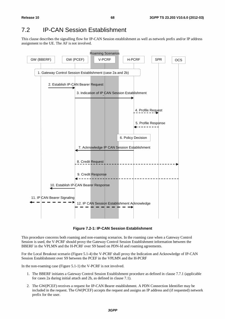
3GPP
3GPP TS 23.203 V10.6.0 (2012-03) 68Release 10
7.2 IP-CAN Session Establishment This clause describes the signalling flow for IP-CAN Session establishment as well as network prefix and/or IP address assignment to the UE. The AF is not involved.
GW (BBERF) GW (PCEF) V - PCRF H- PCRF SPR OCS
Roaming Scenarios
1. Gateway Control Session Est ablishment (case 2a and 2b)
6. Policy Decision
2. Establish IP -CAN Bearer Request
- 3. Indication of IP CAN Session Establishment
4. Profile Request
5. Profile Response
7. Acknowledge IP CAN Session Establishment
8. Credit Request
9. Credit Response
10. Establish IP - CAN Bearer Response
11. IP CAN Bearer Signaling 12. IP CAN Session Establishment Acknowledge
Figure 7.2-1: IP-CAN Session Establishment
This procedure concerns both roaming and non-roaming scenarios. In the roaming case when a Gateway Control Session is used, the V-PCRF should proxy the Gateway Control Session Establishment information between the BBERF in the VPLMN and the H-PCRF over S9 based on PDN-Id and roaming agreements.
For the Local Breakout scenario (Figure 5.1-4) the V-PCRF shall proxy the Indication and Acknowledge of IP-CAN Session Establishment over S9 between the PCEF in the VPLMN and the H-PCRF
In the non-roaming case (Figure 5.1-1) the V-PCRF is not involved.
1. The BBERF initiates a Gateway Control Session Establishment procedure as defined in clause 7.7.1 (applicable for cases 2a during initial attach and 2b, as defined in clause 7.1).
2. The GW(PCEF) receives a request for IP-CAN Bearer establishment. A PDN Connection Identifier may be included in the request. The GW(PCEF) accepts the request and assigns an IP address and (if requested) network prefix for the user.
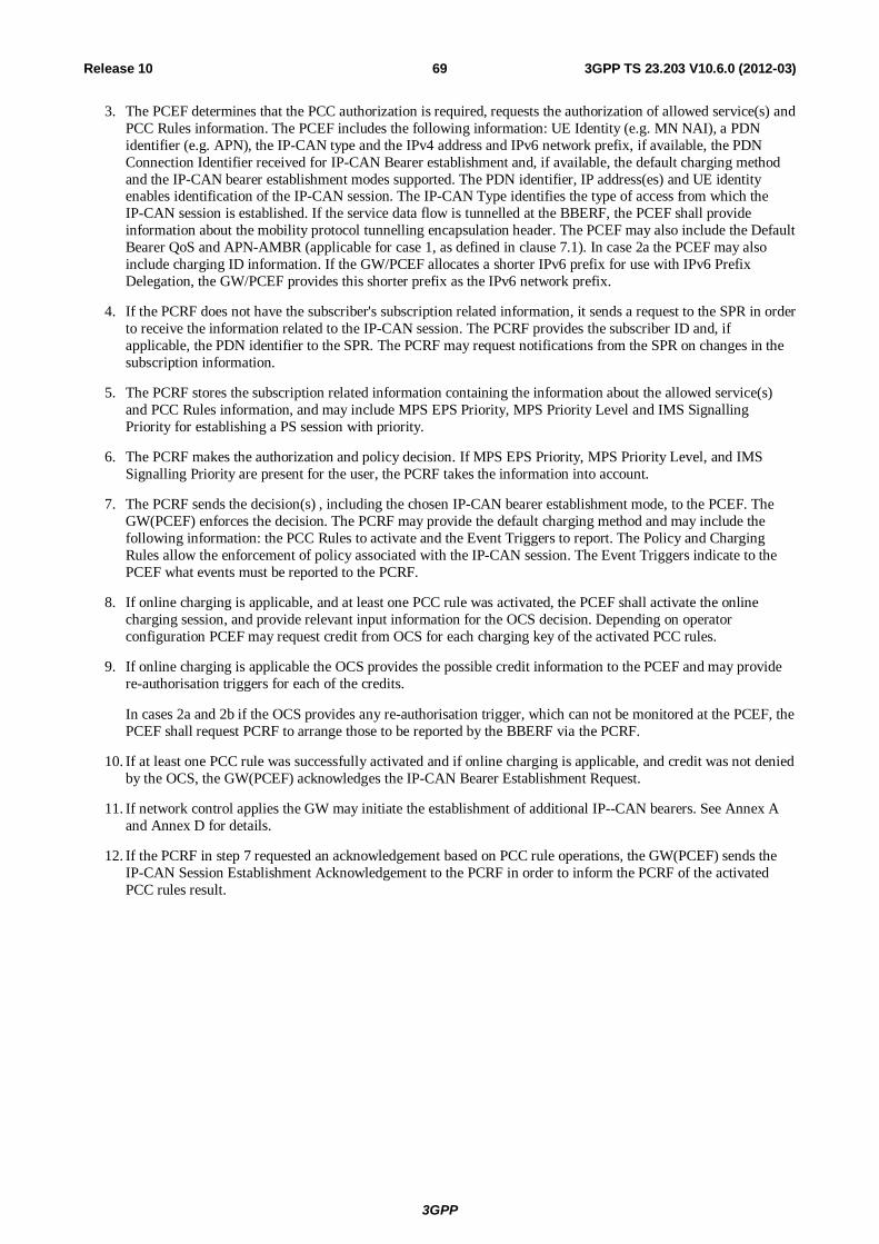
3GPP
3GPP TS 23.203 V10.6.0 (2012-03) 69Release 10
3. The PCEF determines that the PCC authorization is required, requests the authorization of allowed service(s) and PCC Rules information. The PCEF includes the following information: UE Identity (e.g. MN NAI), a PDN identifier (e.g. APN), the IP-CAN type and the IPv4 address and IPv6 network prefix, if available, the PDN Connection Identifier received for IP-CAN Bearer establishment and, if available, the default charging method and the IP-CAN bearer establishment modes supported. The PDN identifier, IP address(es) and UE identity enables identification of the IP-CAN session. The IP-CAN Type identifies the type of access from which the IP-CAN session is established. If the service data flow is tunnelled at the BBERF, the PCEF shall provide information about the mobility protocol tunnelling encapsulation header. The PCEF may also include the Default Bearer QoS and APN-AMBR (applicable for case 1, as defined in clause 7.1). In case 2a the PCEF may also include charging ID information. If the GW/PCEF allocates a shorter IPv6 prefix for use with IPv6 Prefix Delegation, the GW/PCEF provides this shorter prefix as the IPv6 network prefix.
4. If the PCRF does not have the subscriber's subscription related information, it sends a request to the SPR in order to receive the information related to the IP-CAN session. The PCRF provides the subscriber ID and, if applicable, the PDN identifier to the SPR. The PCRF may request notifications from the SPR on changes in the subscription information.
5. The PCRF stores the subscription related information containing the information about the allowed service(s) and PCC Rules information, and may include MPS EPS Priority, MPS Priority Level and IMS Signalling Priority for establishing a PS session with priority.
6. The PCRF makes the authorization and policy decision. If MPS EPS Priority, MPS Priority Level, and IMS Signalling Priority are present for the user, the PCRF takes the information into account.
7. The PCRF sends the decision(s) , including the chosen IP-CAN bearer establishment mode, to the PCEF. The GW(PCEF) enforces the decision. The PCRF may provide the default charging method and may include the following information: the PCC Rules to activate and the Event Triggers to report. The Policy and Charging Rules allow the enforcement of policy associated with the IP-CAN session. The Event Triggers indicate to the PCEF what events must be reported to the PCRF.
8. If online charging is applicable, and at least one PCC rule was activated, the PCEF shall activate the online charging session, and provide relevant input information for the OCS decision. Depending on operator configuration PCEF may request credit from OCS for each charging key of the activated PCC rules.
9. If online charging is applicable the OCS provides the possible credit information to the PCEF and may provide re-authorisation triggers for each of the credits.
In cases 2a and 2b if the OCS provides any re-authorisation trigger, which can not be monitored at the PCEF, the PCEF shall request PCRF to arrange those to be reported by the BBERF via the PCRF.
10. If at least one PCC rule was successfully activated and if online charging is applicable, and credit was not denied by the OCS, the GW(PCEF) acknowledges the IP-CAN Bearer Establishment Request.
11. If network control applies the GW may initiate the establishment of additional IP--CAN bearers. See Annex A and Annex D for details.
12. If the PCRF in step 7 requested an acknowledgement based on PCC rule operations, the GW(PCEF) sends the IP-CAN Session Establishment Acknowledgement to the PCRF in order to inform the PCRF of the activated PCC rules result.
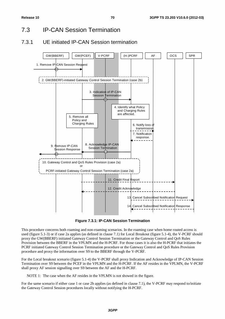
3GPP
3GPP TS 23.203 V10.6.0 (2012-03) 70Release 10
7.3 IP-CAN Session Termination
7.3.1 UE initiated IP-CAN Session termination
GW(BBERF) (H-)PCRF AF OCS SPR GW(PCEF) V-PCRF
3. Indication of IP-CAN Session Termination
4. Identify what Policy and Charging Rules are affected.
5. Remove all Policy and Charging Rules 6. Notify loss of
transmission.
7. Notification response.
9. Remove IP-CAN Session Response
11. Credit Final Report
12. Credit Acknowledge
13. Cancel Subscribed Notification Request 14. Cancel Subscribed Notification Response
8. Acknowledge IP-CAN Session Termination
2. GW(BBERF)-initiated Gateway Control Session Termination (case 2b)
10. Gateway Control and QoS Rules Provision (case 2a) or
PCRF-initiated Gateway Control Session Termination (case 2a)
1. Remove IP-CAN Session Request
Figure 7.3.1: IP-CAN Session Termination
This procedure concerns both roaming and non-roaming scenarios. In the roaming case when home routed access is used (figure 5.1-3) or if case 2a applies (as defined in clause 7.1) for Local Breakout (figure 5.1-4), the V-PCRF should proxy the GW(BBERF) initiated Gateway Control Session Termination or the Gateway Control and QoS Rules Provision between the BBERF in the VPLMN and the H-PCRF. For those cases it is also the H-PCRF that initiates the PCRF initiated Gateway Control Session Termination procedure or the Gateway Control and QoS Rules Provision procedure and proxy the information over S9 to the BBERF through the V-PCRF.
For the Local breakout scenario (figure 5.1-4) the V-PCRF shall proxy Indication and Acknowledge of IP-CAN Session Termination over S9 between the PCEF in the VPLMN and the H-PCRF. If the AF resides in the VPLMN, the V-PCRF shall proxy AF session signalling over S9 between the AF and the H-PCRF.
NOTE 1: The case when the AF resides in the VPLMN is not showed in the figure.
For the same scenario if either case 1 or case 2b applies (as defined in clause 7.1), the V-PCRF may respond to/initiate the Gateway Control Session procedures locally without notifying the H-PCRF.
3GPP
3GPP TS 23.203 V10.6.0 (2012-03) 71Release 10
In the non-roaming case (figure 5.1-1) the V-PCRF is not involved at all.
1. If case 2b applies, the GW(BBERF) receives a request to remove the IP-CAN session. In case 2a, the request goes transparently through the GW(BBERF). In all cases, the GW(PCEF) receives a request to remove the IP-CAN session.
2. If case 2b applies, the GW(BBERF)-initiated GW Control Session Termination procedure as defined in clause 7.7.2.1 is initiated.
3. The GW(PCEF) indicates that the IP-CAN Session is being removed and provides relevant information to the PCRF.
NOTE 2: The GW(PCEF) may proceed to step 9 in parallel with the indication of IP-CAN Session termination.
4. The PCRF finds the PCC Rules that require an AF to be notified and removes PCC Rules for the IP-CAN session.
5. The GW(PCEF) removes all PCC Rules associated with the IP-CAN session.
6. The PCRF notifies the AF that there are no transmission resources for the service if this is requested by the AF.
7. The AF acknowledges the notification of the loss of transmission resources.
8. The PCRF removes the information related to the terminated IP-CAN Session (subscription information etc.), and acknowledges to the GW(PCEF) that the PCRF handling of the IP-CAN session has terminated. This interaction is the response to the GW(PCEF) request in step 3.
9. The GW(PCEF) continues the IP-CAN Session removal procedure.
10. If case 2a applies, the GW Control and QoS Rules Provision procedure as defined in clause 7.7.4 may be initiated to remove the QoS rules associated with the IP-CAN session being terminated. This applies e.g. in case the Gateway Control Session shall remain to serve other IP-CAN sessions.
Alternatively, if case 2a applies and the PCRF determines that all QoS rules are to be removed and the Gateway Control Session shall be terminated, the PCRF-initiated GW Control Session Termination procedure as defined in clause 7.7.2.2 is initiated. This applies e.g. in case the UE is detached and the CoA acquired by the UE is not used for any other IP-CAN session.
11. If online charging is applicable, the PCEF issues final reports and returns the remaining credit to the OCS.
NOTE 3: Step 11 may be initiated any time after step 8.
12. If online charging is applicable the OCS acknowledges that credit report and terminates the online charging session.
13. The PCRF sends a cancellation notification request to the SPR if it has subscribed such notification. If all IP-CAN sessions of the user to the same APN are terminated, the PCRF stores the remaining usage allowance in the SPR.
NOTE 4: Step 13 may be initiated any time after step 8.
14. The SPR sends a response to the PCRF.
NOTE 5: The IP-CAN Session removal procedure may proceed in parallel with the indication of IP-CAN Session termination.
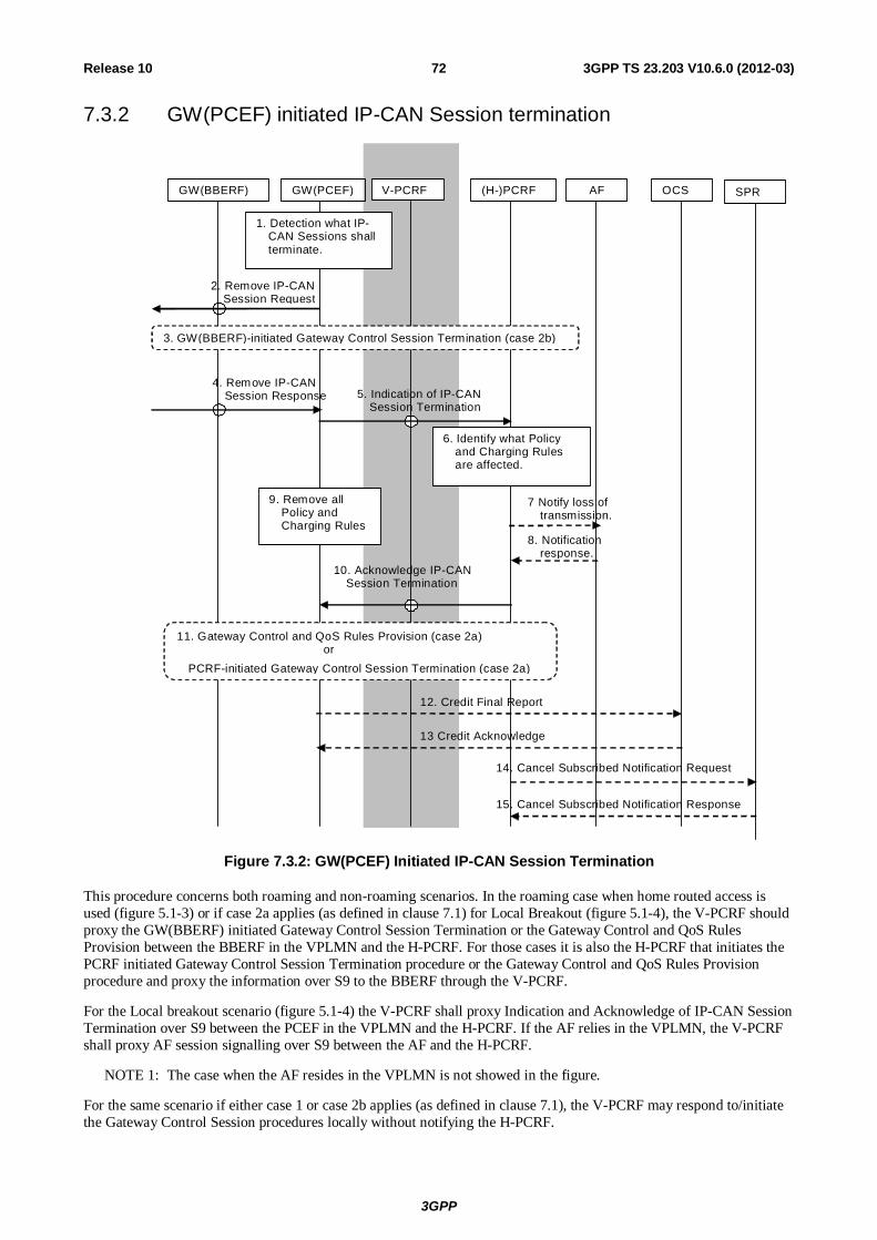
3GPP
3GPP TS 23.203 V10.6.0 (2012-03) 72Release 10
7.3.2 GW(PCEF) initiated IP-CAN Session termination
GW(BBERF) (H-)PCRF AF OCS SPR GW(PCEF) V-PCRF
4. Remove IP-CAN Session Response 5. Indication of IP-CAN
Session Termination
10. Acknowledge IP-CAN Session Termination
13 Credit Acknowledge
7 Notify loss of transmission.
8. Notification response.
14. Cancel Subscribed Notification Request 15. Cancel Subscribed Notification Response
2. Remove IP-CAN Session Request
12. Credit Final Report
3. GW(BBERF)-initiated Gateway Control Session Termination (case 2b)
6. Identify what Policy and Charging Rules are affected.
1. Detection what IP-CAN Sessions shall terminate.
9. Remove all Policy and Charging Rules
11. Gateway Control and QoS Rules Provision (case 2a) or
PCRF-initiated Gateway Control Session Termination (case 2a)
Figure 7.3.2: GW(PCEF) Initiated IP-CAN Session Termination
This procedure concerns both roaming and non-roaming scenarios. In the roaming case when home routed access is used (figure 5.1-3) or if case 2a applies (as defined in clause 7.1) for Local Breakout (figure 5.1-4), the V-PCRF should proxy the GW(BBERF) initiated Gateway Control Session Termination or the Gateway Control and QoS Rules Provision between the BBERF in the VPLMN and the H-PCRF. For those cases it is also the H-PCRF that initiates the PCRF initiated Gateway Control Session Termination procedure or the Gateway Control and QoS Rules Provision procedure and proxy the information over S9 to the BBERF through the V-PCRF.
For the Local breakout scenario (figure 5.1-4) the V-PCRF shall proxy Indication and Acknowledge of IP-CAN Session Termination over S9 between the PCEF in the VPLMN and the H-PCRF. If the AF relies in the VPLMN, the V-PCRF shall proxy AF session signalling over S9 between the AF and the H-PCRF.
NOTE 1: The case when the AF resides in the VPLMN is not showed in the figure.
For the same scenario if either case 1 or case 2b applies (as defined in clause 7.1), the V-PCRF may respond to/initiate the Gateway Control Session procedures locally without notifying the H-PCRF.
3GPP
3GPP TS 23.203 V10.6.0 (2012-03) 73Release 10
In the non-roaming case (figure 5.1-1) the V-PCRF is not involved at all.
1. The GW(PCEF) detects that IP-CAN Session termination is required.
2. The GW(PCEF) sends a request to remove the IP-CAN session.
3. If case 2b applies, the GW(BBERF)-initiated GW Control Session Termination procedure as defined in clause 7.7.2.1 is initiated.
4. The GW(PCEF) receives the response for the IP-CAN session removal.
5. The GW(PCEF) indicates the IP-CAN Session termination and provides the relevant information to the PCRF.
6. The PCRF finds the PCC Rules that require an AF to be notified.
7. The PCRF notifies the AF that there are no transmission resources for the service if this is requested by the AF.
8. The AF acknowledges the notification on the loss of transmission resources.
9. The GW(PCEF) removes all the PCC Rules associated with the IP-CAN session.
10. The PCRF removes the information related to the terminated IP-CAN Session (subscription information etc.), and acknowledges the IP-CAN Session termination.
11. If case 2a applies, the GW Control and QoS Rules Provision procedure as defined in clause 7.7.4 may be initiated to remove the QoS rules associated with the IP-CAN session being terminated. This applies e.g. in case the Gateway Control Session shall remain to serve other IP-CAN sessions.
Alternatively, if case 2a applies and the PCRF determines that the Gateway Control session shall be terminated, the PCRF-initiated GW Control Session Termination procedure as defined in clause 7.7.2.2 is initiated. This applies e.g. in case the UE is detached and the CoA acquired by the UE is not used for any other IP-CAN session.
12. If online charging is applicable, the GW issues final reports and returns the remaining credit to the OCS.
NOTE 2: Step 12 may be initiated any time after step 10.
13. If online charging is applicable the OCS acknowledges the credit report and terminates the online charging session.
14. The PCRF sends a cancellation notification request to the SPR if it has subscribed such notification. If all IP-CAN sessions of the user to the same APN are terminated, the PCRF stores the remaining usage allowance in the SPR.
NOTE 3: Step 14 may be initiated any time after step 8.
15. The SPR sends a response to the PCRF.
7.4 IP-CAN Session Modification
7.4.1 IP-CAN Session Modification; GW(PCEF) initiated This sub-clause describes the signalling flow for the IP-CAN Session modification initiated by the GW(PCEF). These modifications include IP-CAN bearer establishment and termination as well as modification if the triggering conditions given to the PCEF are fulfilled.
The AF may be involved. An example of the scenario is authorization of a session-based service for which an IP-CAN Session is also modified.
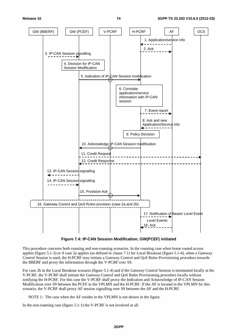
3GPP
3GPP TS 23.203 V10.6.0 (2012-03) 74Release 10
GW (BBERF)
10. Acknowledge IP-CAN Session modification
11. Credit Request
12. Credit Response
GW (PCEF) V-PCRF AF OCS
6. Correlate application/service information with IP-CAN session
16. Gateway Control and QoS Rules provision (case 2a and 2b)
9. Policy Decision
14. IP-CAN Session signalling
18. Ack
17. Notification of Bearer Level Event
Level Events
7. Event report
8. Ack and new Application/Service info
1. Application/service info
4. Decision for IP-CAN Session Modification
13. IP-CAN Session signalling
15. Provision Ack
5. Indication of IP-CAN Session modification
3. IP-CAN Session signalling
H-PCRF
2. Ack
Figure 7.4: IP-CAN Session Modification; GW(PCEF) initiated
This procedure concerns both roaming and non-roaming scenarios. In the roaming case when home routed access applies (figure 5.1-3) or if case 2a applies (as defined in clause 7.1) for Local Breakout (figure 5.1-4), when a Gateway Control Session is used, the H-PCRF may initiate a Gateway Control and QoS Rules Provisioning procedure towards the BBERF and proxy the information through the V-PCRF over S9.
For case 2b in the Local Breakout scenario (figure 5.1-4) and if the Gateway Control Session is terminated locally at the V-PCRF, the V-PCRF shall initiate the Gateway Control and QoS Rules Provisioning procedure locally without notifying the H-PCRF. For this case the V-PCRF shall proxy the Indication and Acknowledge of IP-CAN Session Modification over S9 between the PCEF in the VPLMN and the H-PCRF. If the AF is located in the VPLMN for this scenario, the V-PCRF shall proxy AF session signalling over S9 between the AF and the H-PCRF.
NOTE 1: The case when the AF resides in the VPLMN is not shown in the figure.
In the non-roaming case (figure 5.1-1) the V-PCRF is not involved at all.
3GPP
3GPP TS 23.203 V10.6.0 (2012-03) 75Release 10
1. Optionally, the AF provides/revokes service information to the PCRF due to AF session signalling. The AF may subscribe at this point to notification of bearer level events related to the service information.
NOTE 2: For the PCRF to generate the applicable events, the PCRF instructs the PCEF to report events related to the corresponding PCC rules. Such events are not shown in this sequence diagram.
2. The PCRF stores the service information and responds with the Acknowledgement to the AF.
3. The GW(PCEF) may receive IP-CAN session signalling for IP-CAN Session modification. PDN Connection Identifier may be included in the IP-CAN session signalling.
4. The GW(PCEF) makes a decision to trigger IP-CAN Session modification either caused by the previous step or based on an internal decision.
5. The GW(PCEF) determines that the PCC interaction is required and sends an Indication of IP-CAN Session modification (Event Report, affected PCC Rules, if available, the PDN Connection Identifier) to the PCRF and, if changed, the new IP-CAN bearer establishment modes supported. If there is a limitation or termination of the transmission resources for a PCC Rule, the GW(PCEF) reports this to the PCRF. If flow mobility applies, the GW(PCEF) may include updated IP flow mobility routing information for any IP flows; the GW(PCEF) also provides an indication if default route for the IP-CAN session is changed.
6. The PCRF correlates the request for PCC Rules with the IP-CAN session and service information available at the GW(PCEF).
7. The PCRF may need to report to the AF an event related to the transmission resources if the AF requested it at initial authorisation.
8. The AF acknowledges the event report and/or responds with the requested information.
9. The PCRF makes the authorization and policy decision.
10. The PCRF sends an Acknowledge of IP-CAN Session modification (PCC Rules, Event Triggers and, if changed, the chosen IP-CAN bearer establishment mode) to the GW(PCEF). The GW(PCEF) enforces the decision.
11. If online charging is applicable, the GW(PCEF) may request credit for new charging keys from and/or shall issue final reports and return remaining credit for charging keys no longer active to the OCS.
12. If OCS was contacted, the OCS provides the credit information to the GW(PCEF), and/or acknowledges the credit report.
13 The GW(PCEF) acknowledges or rejects any IP-CAN Session signalling received in step 3.
An IP-CAN bearer establishment is accepted if at least one PCC rule is active for the IP-CAN bearer and in case of online charging credit was not denied by the OCS. Otherwise, the IP-CAN bearer establishment is rejected.
An IP-CAN bearer termination is always acknowledged by the GW(PCEF).
An IP-CAN bearer modification not upgrading the QoS and not providing traffic mapping information is always acknowledged by the GW(PCEF). An IP-CAN bearer modification is accepted if the provided traffic mapping information is accepted by the PCRF. Otherwise, the IP-CAN bearer modification is rejected.
In case of a GW(PCEF) internal decision the GW(PCEF) initiates any additional IP-CAN Session signalling required for completion of the IP-CAN Session modification (applicable for case 1).
In case the IP-CAN session modification is due to the BBF transitioning from a BBERF in the source access-network to the PCEF, the PCEF initiates IP-CAN bearer signalling to activate bearers in the target access network (applicable for case 1).
14. The GW(PCEF) receives the response for the IP-CAN Session signalling request (applicable for case 1).
15. The GW(PCEF) sends a Provision Ack (accept or reject of the PCC rule operation(s)) to inform the PCRF about the outcome of the GW(PCEF) actions related to the decision(s) received in step 10.
NOTE 3: For Cases 2a and 2b, the rejection of PCC rule operation can only occur as a result of online charging interaction.
3GPP
3GPP TS 23.203 V10.6.0 (2012-03) 76Release 10
16. Based on the result of PCC rule operations, the PCRF decides whether to initiate a Gateway Control and QoS Rules provision procedure as defined in clause 7.7.4, if required to keep the PCC and QoS rules aligned (applicable for case 2a and 2b, as defined in clause 7.1).
If there are multiple BBERFs associated with the IP-CAN session, this step is performed with all the affected BBERFs.
17. If the AF requested it, the PCRF notifies the AF of related bearer level events (e.g. transmission resources are established/released/lost).
NOTE 3: Based on the outcome reported in this step the AF performs the appropriate action, e.g. starting charging or terminating the AF session.
18. The AF acknowledges the notification from the PCRF.
7.4.2 IP-CAN Session Modification; PCRF initiated This clause describes the signalling flow for the IP-CAN Session modification initiated by the PCRF. The AF may be involved. An example of the scenario is initiation and authorization of a session-based service for which an IP-CAN Session is modified. IP-CAN Session handling and handling of PCC rules for non-session based services, and also general handling of PCC rules that are not subject to AF-interaction is also applicable here.
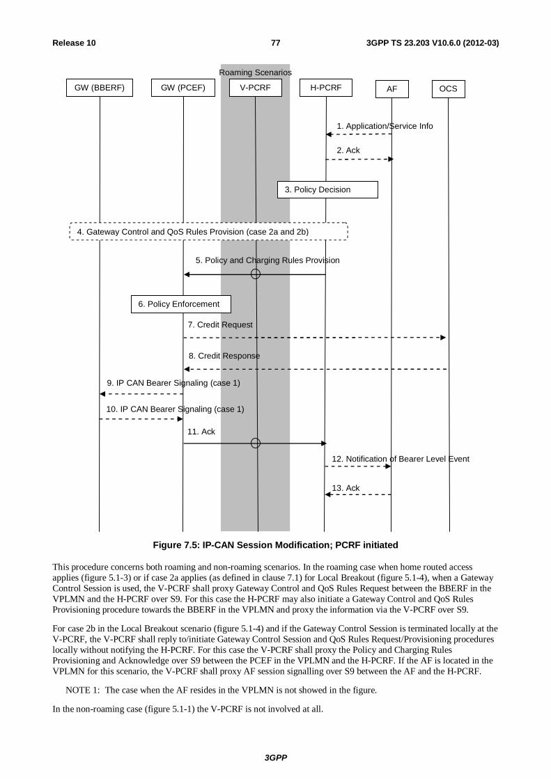
3GPP
3GPP TS 23.203 V10.6.0 (2012-03) 77Release 10
9. IP CAN Bearer Signaling (case 1)
GW (PCEF) V-PCRF H-PCRF AF
Roaming Scenarios
3. Policy Decision
5. Policy and Charging Rules Provision
11. Ack
7. Credit Request
8. Credit Response
OCS
6. Policy Enforcement
10. IP CAN Bearer Signaling (case 1)
4. Gateway Control and QoS Rules Provision (case 2a and 2b)
GW (BBERF)
12. Notification of Bearer Level Event
13. Ack
1. Application/Service Info
2. Ack
Figure 7.5: IP-CAN Session Modification; PCRF initiated
This procedure concerns both roaming and non-roaming scenarios. In the roaming case when home routed access applies (figure 5.1-3) or if case 2a applies (as defined in clause 7.1) for Local Breakout (figure 5.1-4), when a Gateway Control Session is used, the V-PCRF shall proxy Gateway Control and QoS Rules Request between the BBERF in the VPLMN and the H-PCRF over S9. For this case the H-PCRF may also initiate a Gateway Control and QoS Rules Provisioning procedure towards the BBERF in the VPLMN and proxy the information via the V-PCRF over S9.
For case 2b in the Local Breakout scenario (figure 5.1-4) and if the Gateway Control Session is terminated locally at the V-PCRF, the V-PCRF shall reply to/initiate Gateway Control Session and QoS Rules Request/Provisioning procedures locally without notifying the H-PCRF. For this case the V-PCRF shall proxy the Policy and Charging Rules Provisioning and Acknowledge over S9 between the PCEF in the VPLMN and the H-PCRF. If the AF is located in the VPLMN for this scenario, the V-PCRF shall proxy AF session signalling over S9 between the AF and the H-PCRF.
NOTE 1: The case when the AF resides in the VPLMN is not showed in the figure.
In the non-roaming case (figure 5.1-1) the V-PCRF is not involved at all.
3GPP
3GPP TS 23.203 V10.6.0 (2012-03) 78Release 10
1. Optionally, the AF provides/revokes service information to the PCRF due to AF session signalling. The AF may subscribe at this point to notification of bearer level events related to the service information.
NOTE 2: For the PCRF to generate the applicable events, the PCRF instructs the PCEF to report events related to the corresponding PCC rules. Such events are not shown in this sequence diagram.
2. The PCRF stores the service information if available and responds with the Acknowledgement to the AF.
NOTE 3: Without AF interaction, a trigger event in the PCRF may cause the PCRF to determine that the PCC rules require updating at the PCEF, e.g. change to configured policy.
NOTE 4: This procedure could also be triggered by the Gateway Control and QoS Rules Request procedure as described in clause 7.7.3.
3. The PCRF makes the authorization and policy decision.
4. If there is no Gateway Control and QoS Rules Reply pending and there is a need to provision QoS rules, the PCRF initiates a Gateway Control and QoS Rules Provision Procedure as defined in 7.7.4 (applicable for cases 2a and 2b, as defined in clause 7.1).
If there are multiple BBERFs associated with the IP-CAN session, Step 4 is performed with the BBERFs that support UE/NW bearer establishment mode.
NOTE 5: If there is a Gateway Control and QoS Rules Reply pending, e.g. this procedure was invoked from the Gateway Control and QoS Rules Request procedure as defined in clause 7.7.3, the PCRF shall use that opportunity for provisioning the applicable QoS rules. If there are multiple BBERFs associated with the IP-CAN session, and the procedure was invoked by a Gateway Control and QoS Rules Request procedure from the primary BBERF, the PCRF may receive a Gateway Control and QoS Rules Request from the non-primary BBERFs.
5. The PCRF sends the Policy and Charging Rules Provision (PCC Rules, Event Trigger, Event Report) to the PCEF.
6. The PCEF enforces the decision.
7. If online charging is applicable, the PCEF may request credit for new charging keys from and/or shall return the remaining credit for charging keys no longer active to the OCS.
8. If OCS was involved, the OCS provides the credit information to the PCEF, and/or acknowledges the credit report
9. The GW(PCEF) may send an IP-CAN Bearer establishment, modification or termination request (applicable for case 1, as defined in clause 7.1).
An IP-CAN bearer modification is sent by the GW(PCEF) if the QoS of the IP-CAN bearer exceeds the authorized QoS provided by the PCRF in step 3.
An IP-CAN bearer termination request is sent by the GW(PCEF) if all PCC rules for an IP-CAN bearer have been removed.
10. The GW(PCEF) receives the response for the IP-CAN Bearer modification or termination request (applicable for case 1).
11. The PCEF sends Acknowledge Policy and Charging Rules Provisioning (accept or reject of the PCC rule operation(s)) to the PCRF.
12. If the AF requested it, the PCRF notifies the AF related bearer level events (e.g. transmission resources are established/released/lost).
13. The AF acknowledges the notification from the PCRF.
7.4.3 Void
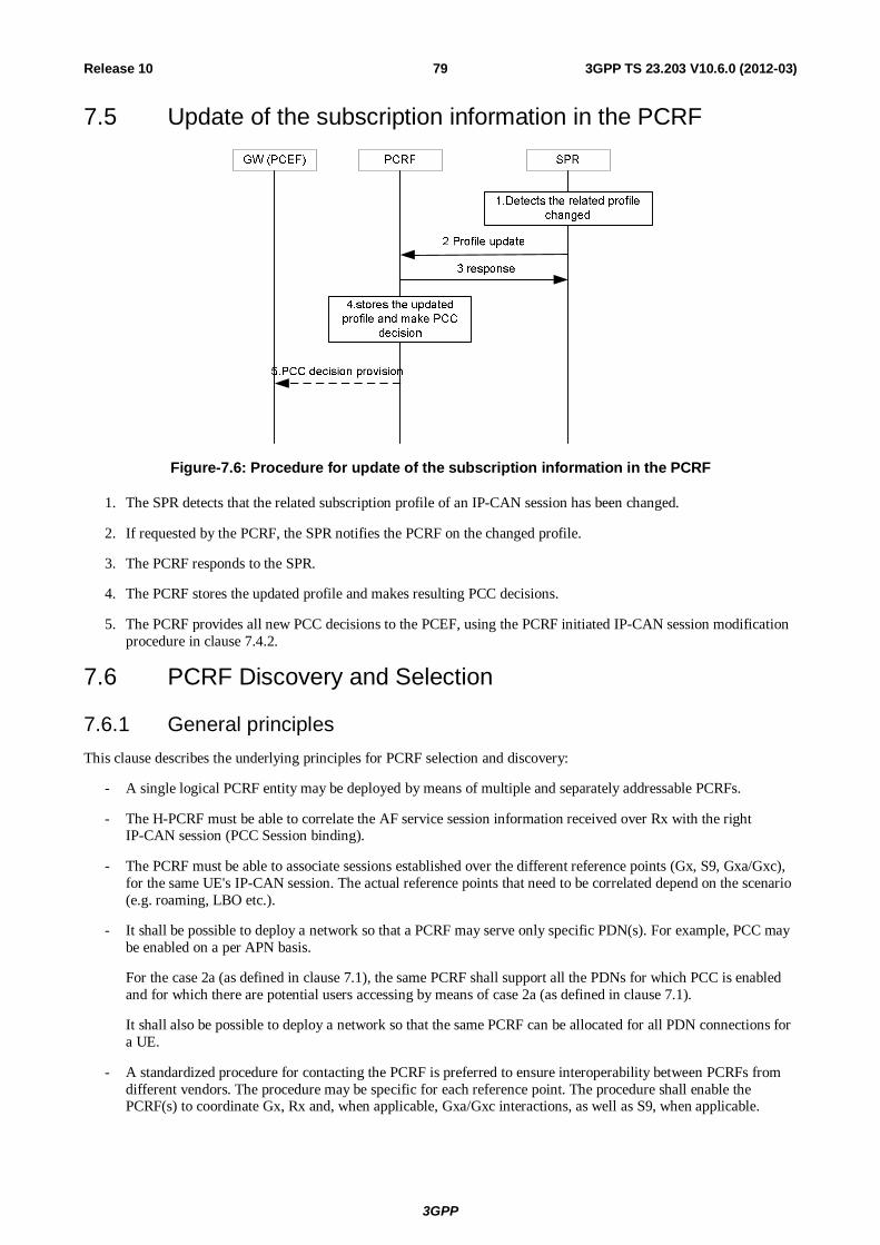
3GPP
3GPP TS 23.203 V10.6.0 (2012-03) 79Release 10
7.5 Update of the subscription information in the PCRF
Figure-7.6: Procedure for update of the subscription information in the PCRF
1. The SPR detects that the related subscription profile of an IP-CAN session has been changed.
2. If requested by the PCRF, the SPR notifies the PCRF on the changed profile.
3. The PCRF responds to the SPR.
4. The PCRF stores the updated profile and makes resulting PCC decisions.
5. The PCRF provides all new PCC decisions to the PCEF, using the PCRF initiated IP-CAN session modification procedure in clause 7.4.2.
7.6 PCRF Discovery and Selection
7.6.1 General principles This clause describes the underlying principles for PCRF selection and discovery:
- A single logical PCRF entity may be deployed by means of multiple and separately addressable PCRFs.
- The H-PCRF must be able to correlate the AF service session information received over Rx with the right IP-CAN session (PCC Session binding).
- The PCRF must be able to associate sessions established over the different reference points (Gx, S9, Gxa/Gxc), for the same UE's IP-CAN session. The actual reference points that need to be correlated depend on the scenario (e.g. roaming, LBO etc.).
- It shall be possible to deploy a network so that a PCRF may serve only specific PDN(s). For example, PCC may be enabled on a per APN basis.
For the case 2a (as defined in clause 7.1), the same PCRF shall support all the PDNs for which PCC is enabled and for which there are potential users accessing by means of case 2a (as defined in clause 7.1).
It shall also be possible to deploy a network so that the same PCRF can be allocated for all PDN connections for a UE.
- A standardized procedure for contacting the PCRF is preferred to ensure interoperability between PCRFs from different vendors. The procedure may be specific for each reference point. The procedure shall enable the PCRF(s) to coordinate Gx, Rx and, when applicable, Gxa/Gxc interactions, as well as S9, when applicable.
3GPP
3GPP TS 23.203 V10.6.0 (2012-03) 80Release 10
- It shall allow that entities contacting the PCRF may be able to provide different sets of information about the UE and PDN connections. For example:
- The AF has information about UE IP address and PDN but may not have user identity information
- The PDN GW has information about user identity (UE NAI), the APN and the UE IP address(es) for a certain PDN connection.
- For case 2b as defined in clause 7.1, the S-GW and trusted non-3GPP access has information about the user identity (UE NAI) and, the APN(s) but may not know the UE IP address(es).
- For case 2a as defined in clause 7.1, the trusted non-3GPP access has information about the user identity (UE NAI) and the local IP address (CoA) but may not know the APN or UE IP address(es) (HoA).
- The DRA has information about the user identity (UE NAI), the APN, the UE IP address(es) and the selected PCRF address for a certain IP-CAN Session.
When the DRA first receives a request for a certain IP-CAN Session (e.g. from the PDN GW), the DRA selects a suitable PCRF for the IP-CAN Session and stores the PCRF address. Subsequently, the DRA can retrieve the selected PCRF address according to the information carried by the incoming requests from other entities (e.g. the AF or the BBERF).
When the IP-CAN Session terminates, the DRA shall remove the information about the IP-CAN Session. In case of the PCRF realm change, the information about the IP-CAN session stored in the old DRA shall be removed.
- All PCRFs in a PLMN belong to one or more Diameter realms. Routing of PCC messages for a UE towards the right Diameter realm in a PLMN is based on standard Diameter routing, as specified in RFC 3588, i.e. based on UE-NAI domain part. A Diameter realm shall provide the ability of routing PCC messages for the same UE and PDN connection to the same PCRF based on the available information supplied by the entities contacting the PCRF.
- A PLMN may be separated into multiple Diameter realms based on the PDN ID information or IP address range. In this case, the relevant information (PDN ID, IP address, etc) shall be used to assist routing PCC message to the appropriate Diameter realm.
- Unique identification of an IP-CAN session in the PCRF shall be possible based on the (UE ID, PDN ID)-tuple , the (UE IP Address(es), PDN ID)-tuple and the (UE ID, UE IP Address(es), PDN ID).
- Standard IETF RFC 3588 mechanisms and components, e.g. Diameter agents, should be applied to deploy a network where the PCRF implementation specifics are invisible for Diameter clients. The use of Diameter agents, including Diameter redirect agents, shall be permitted, but the use of agents in a certain deployment shall be optional.
7.6.2 Solution Principles In order to ensure that all Diameter sessions for Gx, S9, Gxa/Gxc and Rx for a certain IP-CAN session reach the same PCRF when multiple and separately addressable PCRFs have been deployed in a Diameter realm, an optional logical "Diameter Routing Agent (DRA)" function is enabled. This resolution mechanism is not required in networks that utilise a single PCRF per Diameter realm. The DRA has the following roles:
- When deployed, DRA needs to be contacted at first interaction point for a given GW and IP-CAN session.
NOTE: How subsequent interactions work is described in TS 29.213 [22].
- When deployed, the DRA is on the Diameter routing path when initiating a session with a PCRF over Gx, Rx, Gxa/Gxc, and S9.
- The DRA is involved at IP-CAN session establishment by the PDN GW
- The DRA selects the PCRF at initial attach (IP-CAN session or Gateway Control session establishment)
- The DRA is involved at Gateway Control session establishment by the S-GW and trusted non-3GPP access
- After IP-CAN session or Gateway Control Session establishment, the DRA ensures that the same PCRF is contacted for Rx, Gxa/Gxc, Gx and S9.
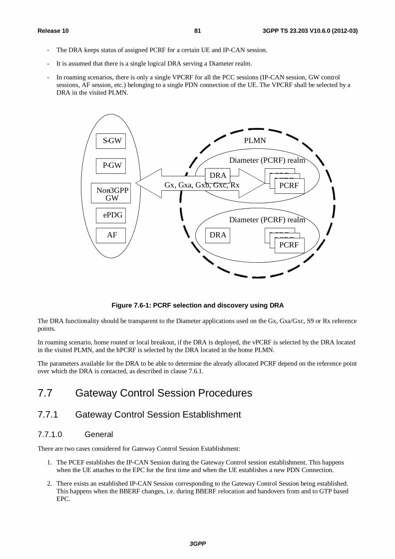
3GPP
3GPP TS 23.203 V10.6.0 (2012-03) 81Release 10
- The DRA keeps status of assigned PCRF for a certain UE and IP-CAN session.
- It is assumed that there is a single logical DRA serving a Diameter realm.
- In roaming scenarios, there is only a single VPCRF for all the PCC sessions (IP-CAN session, GW control sessions, AF session, etc.) belonging to a single PDN connection of the UE. The VPCRF shall be selected by a DRA in the visited PLMN.
PLMN
Diameter (PCRF) realm
S -GW
P -GW
AF
PCRF PCRF PCRF
DRA
Diameter (PCRF) realm
PCRF PCRF PCRF
DRA Gx, Gxa, Gxb, Gxc, Rx
Non-3GPP GW
ePDG
Figure 7.6-1: PCRF selection and discovery using DRA
The DRA functionality should be transparent to the Diameter applications used on the Gx, Gxa/Gxc, S9 or Rx reference points.
In roaming scenario, home routed or local breakout, if the DRA is deployed, the vPCRF is selected by the DRA located in the visited PLMN, and the hPCRF is selected by the DRA located in the home PLMN.
The parameters available for the DRA to be able to determine the already allocated PCRF depend on the reference point over which the DRA is contacted, as described in clause 7.6.1.
7.7 Gateway Control Session Procedures
7.7.1 Gateway Control Session Establishment
7.7.1.0 General
There are two cases considered for Gateway Control Session Establishment:
1. The PCEF establishes the IP-CAN Session during the Gateway Control session establishment. This happens when the UE attaches to the EPC for the first time and when the UE establishes a new PDN Connection.
2. There exists an established IP-CAN Session corresponding to the Gateway Control Session being established. This happens when the BBERF changes, i.e. during BBERF relocation and handovers from and to GTP based EPC.
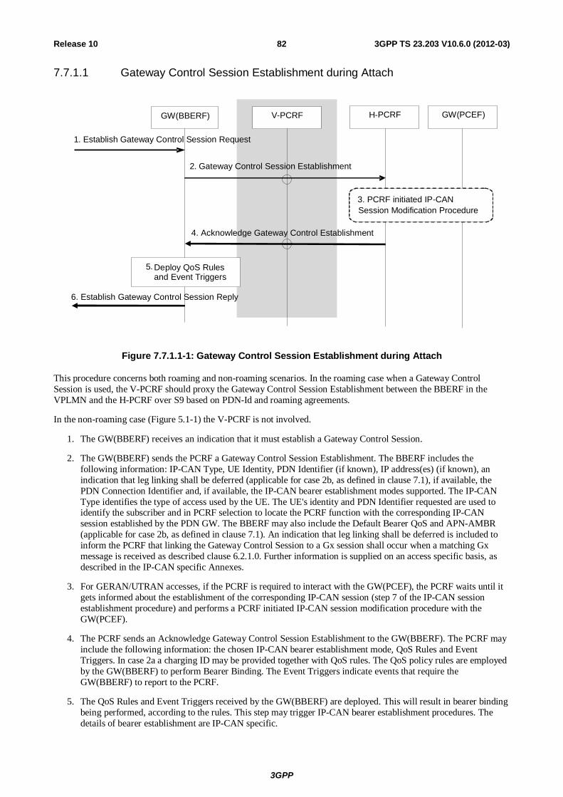
3GPP
3GPP TS 23.203 V10.6.0 (2012-03) 82Release 10
7.7.1.1 Gateway Control Session Establishment during Attach
GW(BBERF) V -PCRF GW(PCEF)
1. Establish Gateway Control Session Request
2. Gateway Control Session Establishment
H-PCRF
3. PCRF initiated IP-CAN Session Modification Procedure
4. Acknowledge Gateway Control Establishment
5. Deploy QoS Rules and Event Triggers
6. Establish Gateway Control Session Reply
Figure 7.7.1.1-1: Gateway Control Session Establishment during Attach
This procedure concerns both roaming and non-roaming scenarios. In the roaming case when a Gateway Control Session is used, the V-PCRF should proxy the Gateway Control Session Establishment between the BBERF in the VPLMN and the H-PCRF over S9 based on PDN-Id and roaming agreements.
In the non-roaming case (Figure 5.1-1) the V-PCRF is not involved.
1. The GW(BBERF) receives an indication that it must establish a Gateway Control Session.
2. The GW(BBERF) sends the PCRF a Gateway Control Session Establishment. The BBERF includes the following information: IP-CAN Type, UE Identity, PDN Identifier (if known), IP address(es) (if known), an indication that leg linking shall be deferred (applicable for case 2b, as defined in clause 7.1), if available, the PDN Connection Identifier and, if available, the IP-CAN bearer establishment modes supported. The IP-CAN Type identifies the type of access used by the UE. The UE's identity and PDN Identifier requested are used to identify the subscriber and in PCRF selection to locate the PCRF function with the corresponding IP-CAN session established by the PDN GW. The BBERF may also include the Default Bearer QoS and APN-AMBR (applicable for case 2b, as defined in clause 7.1). An indication that leg linking shall be deferred is included to inform the PCRF that linking the Gateway Control Session to a Gx session shall occur when a matching Gx message is received as described clause 6.2.1.0. Further information is supplied on an access specific basis, as described in the IP-CAN specific Annexes.
3. For GERAN/UTRAN accesses, if the PCRF is required to interact with the GW(PCEF), the PCRF waits until it gets informed about the establishment of the corresponding IP-CAN session (step 7 of the IP-CAN session establishment procedure) and performs a PCRF initiated IP-CAN session modification procedure with the GW(PCEF).
4. The PCRF sends an Acknowledge Gateway Control Session Establishment to the GW(BBERF). The PCRF may include the following information: the chosen IP-CAN bearer establishment mode, QoS Rules and Event Triggers. In case 2a a charging ID may be provided together with QoS rules. The QoS policy rules are employed by the GW(BBERF) to perform Bearer Binding. The Event Triggers indicate events that require the GW(BBERF) to report to the PCRF.
5. The QoS Rules and Event Triggers received by the GW(BBERF) are deployed. This will result in bearer binding being performed, according to the rules. This step may trigger IP-CAN bearer establishment procedures. The details of bearer establishment are IP-CAN specific.
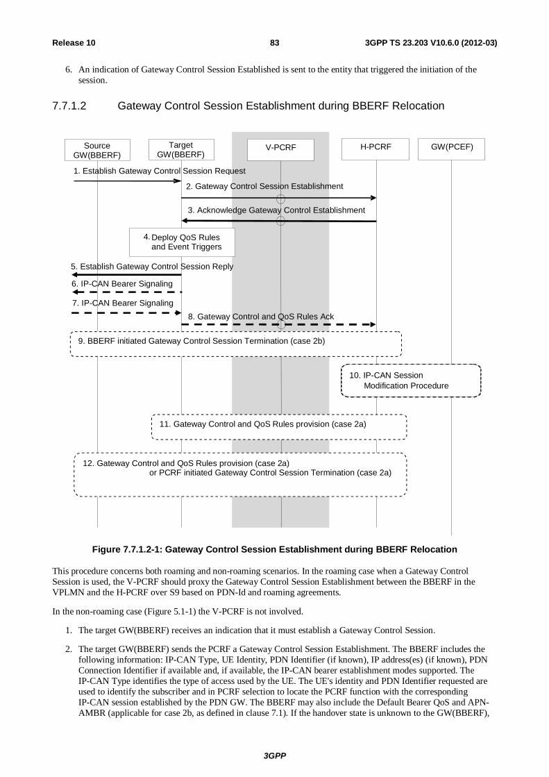
3GPP
3GPP TS 23.203 V10.6.0 (2012-03) 83Release 10
6. An indication of Gateway Control Session Established is sent to the entity that triggered the initiation of the session.
7.7.1.2 Gateway Control Session Establishment during BBERF Relocation
V-PCRF GW(PCEF)
1. Establish Gateway Control Session Request 2. Gateway Control Session Establishment
H-PCRF
10. IP-CAN Session Modification Procedure
8. Gateway Control and QoS Rules Ack
6. IP-CAN Bearer Signaling
7. IP-CAN Bearer Signaling
3. Acknowledge Gateway Control Establishment
4. Deploy QoS Rules and Event Triggers
5. Establish Gateway Control Session Reply
Source GW(BBERF)
Target GW(BBERF)
9. BBERF initiated Gateway Control Session Termination (case 2b)
12. Gateway Control and QoS Rules provision (case 2a) or PCRF initiated Gateway Control Session Termination (case 2a)
11. Gateway Control and QoS Rules provision (case 2a)
Figure 7.7.1.2-1: Gateway Control Session Establishment during BBERF Relocation
This procedure concerns both roaming and non-roaming scenarios. In the roaming case when a Gateway Control Session is used, the V-PCRF should proxy the Gateway Control Session Establishment between the BBERF in the VPLMN and the H-PCRF over S9 based on PDN-Id and roaming agreements.
In the non-roaming case (Figure 5.1-1) the V-PCRF is not involved.
1. The target GW(BBERF) receives an indication that it must establish a Gateway Control Session.
2. The target GW(BBERF) sends the PCRF a Gateway Control Session Establishment. The BBERF includes the following information: IP-CAN Type, UE Identity, PDN Identifier (if known), IP address(es) (if known), PDN Connection Identifier if available and, if available, the IP-CAN bearer establishment modes supported. The IP-CAN Type identifies the type of access used by the UE. The UE's identity and PDN Identifier requested are used to identify the subscriber and in PCRF selection to locate the PCRF function with the corresponding IP-CAN session established by the PDN GW. The BBERF may also include the Default Bearer QoS and APN-AMBR (applicable for case 2b, as defined in clause 7.1). If the handover state is unknown to the GW(BBERF),
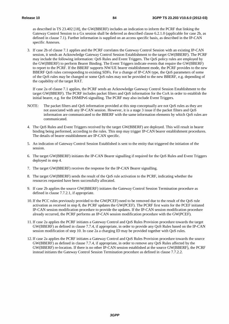
3GPP
3GPP TS 23.203 V10.6.0 (2012-03) 84Release 10
as described in TS 23.402 [18], the GW(BBERF) includes an indication to inform the PCRF that linking the Gateway Control Session to a Gx session shall be deferred as described clause 6.2.1.0 (applicable for case 2b, as defined in clause 7.1). Further information is supplied on an access specific basis, as described in the IP-CAN specific Annexes.
3. If case 2b of clause 7.1 applies and the PCRF correlates the Gateway Control Session with an existing IP-CAN session, it sends an Acknowledge Gateway Control Session Establishment to the target GW(BBERF). The PCRF may include the following information: QoS Rules and Event Triggers. The QoS policy rules are employed by the GW(BBERF) to perform Bearer Binding. The Event Triggers indicate events that require the GW(BBERF) to report to the PCRF. If the BBERF supports NW/UE bearer establishment mode, the PCRF provides to the new BBERF QoS rules corresponding to existing SDFs. For a change of IP-CAN type, the QoS parameters of some of the QoS rules may be changed or some QoS rules may not be provided to the new BBERF, e.g. depending of the capability of the target RAT.
If case 2a of clause 7.1 applies, the PCRF sends an Acknowledge Gateway Control Session Establishment to the target GW(BBERF). The PCRF includes packet filters and QoS information for the CoA in order to establish the initial bearer, e.g. for the DSMIPv6 signalling. The PCRF may also include Event Triggers.
NOTE: The packet filters and QoS information provided at this step conceptually are not QoS rules as they are not associated with any IP-CAN session. However, it is a stage 3 issue if the packet filters and QoS information are communicated to the BBERF with the same information elements by which QoS rules are communicated.
4. The QoS Rules and Event Triggers received by the target GW(BBERF) are deployed. This will result in bearer binding being performed, according to the rules. This step may trigger IP-CAN bearer establishment procedures. The details of bearer establishment are IP-CAN specific.
5. An indication of Gateway Control Session Established is sent to the entity that triggered the initiation of the session.
6. The target GW(BBERF) initiates the IP-CAN Bearer signalling if required for the QoS Rules and Event Triggers deployed in step 4.
7. The target GW(BBERF) receives the response for the IP-CAN Bearer signalling.
8. The target GW(BBERF) sends the result of the QoS rule activation to the PCRF, indicating whether the resources requested have been successfully allocated.
9. If case 2b applies the source GW(BBERF) initiates the Gateway Control Session Termination procedure as defined in clause 7.7.2.1, if appropriate.
10. If the PCC rules previously provided to the GW(PCEF) need to be removed due to the result of the QoS rule activation as received in step 8, the PCRF updates the GW(PCEF). The PCRF first waits for the PCEF initiated IP-CAN session modification procedure to provide the updates. If the IP-CAN session modification procedure already occurred, the PCRF performs an IP-CAN session modification procedure with the GW(PCEF).
11. If case 2a applies the PCRF initiates a Gateway Control and QoS Rules Provision procedure towards the target GW(BBERF) as defined in clause 7.7.4, if appropriate, in order to provide any QoS Rules based on the IP-CAN session modification of step 10. In case 2a a charging ID may be provided together with QoS rules.
12. If case 2a applies the PCRF initiates a Gateway Control and QoS Rules Provision procedure towards the source GW(BBERF) as defined in clause 7.7.4, if appropriate, in order to remove any QoS Rules affected by the GW(BBERF) re-location. If there is no other IP-CAN session established at the source GW(BBERF), the PCRF instead initiates the Gateway Control Session Termination procedure as defined in clause 7.7.2.2.
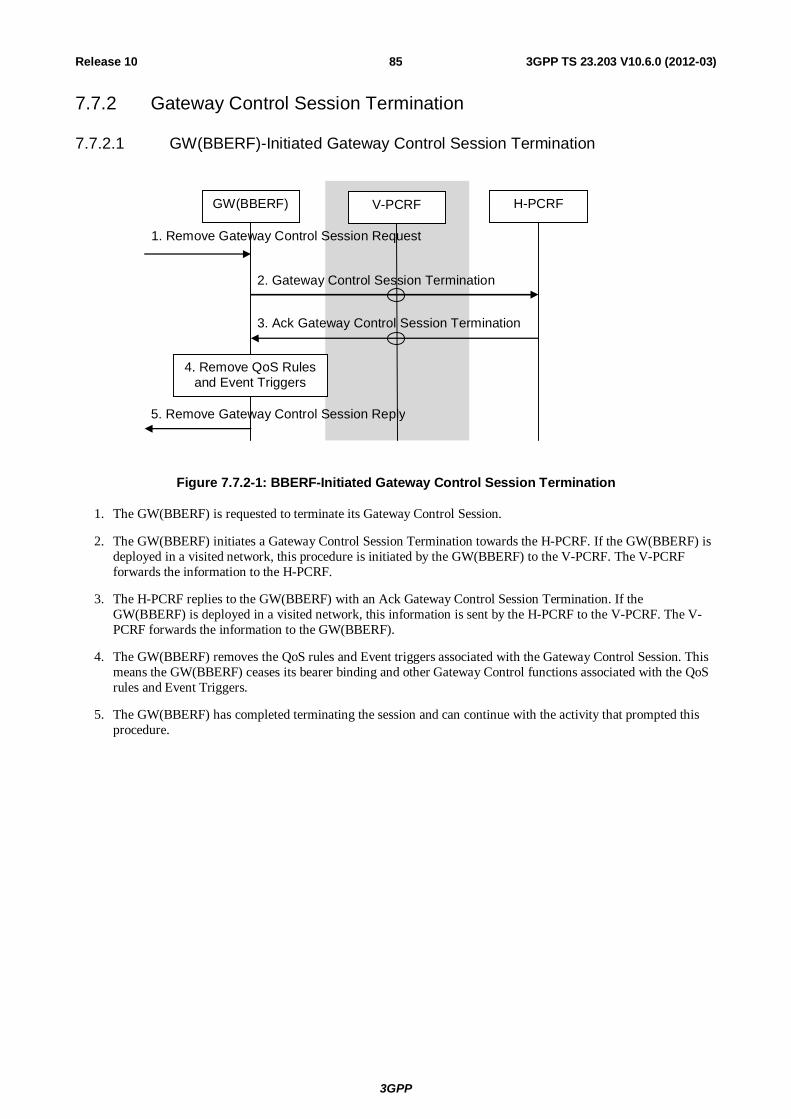
3GPP
3GPP TS 23.203 V10.6.0 (2012-03) 85Release 10
7.7.2 Gateway Control Session Termination
7.7.2.1 GW(BBERF)-Initiated Gateway Control Session Termination
GW(BBERF) V-PCRF H-PCRF
4. Remove QoS Rules and Event Triggers
5. Remove Gateway Control Session Reply
1. Remove Gateway Control Session Request
2. Gateway Control Session Termination
3. Ack Gateway Control Session Termination
Figure 7.7.2-1: BBERF-Initiated Gateway Control Session Termination
1. The GW(BBERF) is requested to terminate its Gateway Control Session.
2. The GW(BBERF) initiates a Gateway Control Session Termination towards the H-PCRF. If the GW(BBERF) is deployed in a visited network, this procedure is initiated by the GW(BBERF) to the V-PCRF. The V-PCRF forwards the information to the H-PCRF.
3. The H-PCRF replies to the GW(BBERF) with an Ack Gateway Control Session Termination. If the GW(BBERF) is deployed in a visited network, this information is sent by the H-PCRF to the V-PCRF. The V-PCRF forwards the information to the GW(BBERF).
4. The GW(BBERF) removes the QoS rules and Event triggers associated with the Gateway Control Session. This means the GW(BBERF) ceases its bearer binding and other Gateway Control functions associated with the QoS rules and Event Triggers.
5. The GW(BBERF) has completed terminating the session and can continue with the activity that prompted this procedure.
3GPP
3GPP TS 23.203 V10.6.0 (2012-03) 86Release 10
7.7.2.2 PCRF-Initiated Gateway Control Session Termination
GW(BBERF) V-PCRF H-PCRF
3. Remove QoS Rules and Event Triggers
2. PCRF Initiated Gateway Control Session Termination
6. PCRF Initiated Gateway Control Session Termination Ack
1. Decision to Remove Gateway Control Session
4. IP-CAN Bearer Removal Request
5. IP-CAN Bearer Removal Reply
Figure 7.7.2-2: PCRF-Initiated Gateway Control Session Termination
This procedure concerns both roaming and non-roaming scenarios. In the roaming case when a Gateway Control Session is used, the V-PCRF should proxy the Gateway Control Session Termination between the BBERF in the VPLMN and the H-PCRF over S9 based on PDN-Id and roaming agreements.
In the non-roaming case (Figure 5.1-1) the V-PCRF is not involved.
1. The PCRF is requested to terminate its Gateway Control Session.
2. The PCRF sends a PCRF-Initiated Gateway Control Session Termination to the GW(BBERF).
3. The GW(BBERF) removes the QoS rules and Event triggers associated with the Gateway Control Session. This means the GW(BBERF) ceases its bearer binding and other Gateway Control functions associated with the QoS rules and Event Triggers.
4. If the bearer(s) corresponding to the removed QoS rules are still established, the GW(BBERF) initiates an IP-CAN specific bearer removal procedure.
5. The GW(BBERF) receives the response for the IP-CAN specific bearer removal procedure.
6. The GW(BBERF) replies to the PCRF with an PCRF-Initiated Gateway Control Session Termination acknowledgement.
7.7.3 Gateway Control and QoS Rules Request
7.7.3.1 General
There are two cases considered for a Gateway Control and QoS Rules Request depending on the parameters the GW(BBERF) receives:
Case A: In case the GW(BBERF) action does not depend on the subsequent IP-CAN session modification, the GW(BBERF) can acknowledge the request after interacting with the PCRF.
NOTE 1: If QoS rules have to be updated due to the event reporting, the PCRF shall use the Gateway Control and QoS Rules Provision procedure.
Case B: The GW(BBERF) is requested to obtain QoS rules for a Gateway Control Session or to deliver IP-CAN-specific parameters or both.
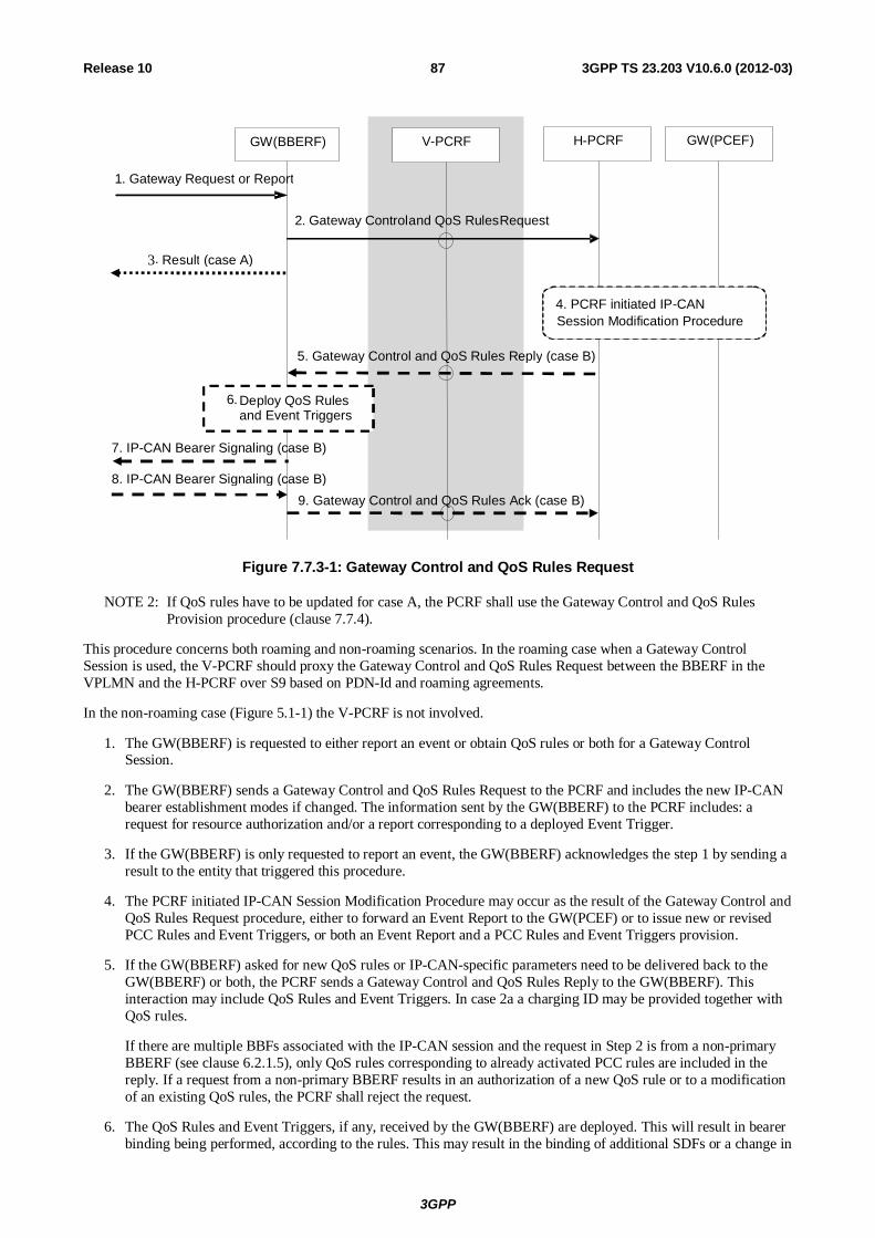
3GPP
3GPP TS 23.203 V10.6.0 (2012-03) 87Release 10
GW(BBERF) V -PCRF GW(PCEF)
1. Gateway Request or Report
2. Gateway Control and QoS Rules Request
H-PCRF
4. PCRF initiated IP-CAN Session Modification Procedure
9. Gateway Control and QoS Rules Ack (case B)
7. IP-CAN Bearer Signaling (case B)
8. IP-CAN Bearer Signaling (case B)
3. Result (case A)
5. Gateway Control and QoS Rules Reply (case B)
6. Deploy QoS Rules and Event Triggers
Figure 7.7.3-1: Gateway Control and QoS Rules Request
NOTE 2: If QoS rules have to be updated for case A, the PCRF shall use the Gateway Control and QoS Rules Provision procedure (clause 7.7.4).
This procedure concerns both roaming and non-roaming scenarios. In the roaming case when a Gateway Control Session is used, the V-PCRF should proxy the Gateway Control and QoS Rules Request between the BBERF in the VPLMN and the H-PCRF over S9 based on PDN-Id and roaming agreements.
In the non-roaming case (Figure 5.1-1) the V-PCRF is not involved.
1. The GW(BBERF) is requested to either report an event or obtain QoS rules or both for a Gateway Control Session.
2. The GW(BBERF) sends a Gateway Control and QoS Rules Request to the PCRF and includes the new IP-CAN bearer establishment modes if changed. The information sent by the GW(BBERF) to the PCRF includes: a request for resource authorization and/or a report corresponding to a deployed Event Trigger.
3. If the GW(BBERF) is only requested to report an event, the GW(BBERF) acknowledges the step 1 by sending a result to the entity that triggered this procedure.
4. The PCRF initiated IP-CAN Session Modification Procedure may occur as the result of the Gateway Control and QoS Rules Request procedure, either to forward an Event Report to the GW(PCEF) or to issue new or revised PCC Rules and Event Triggers, or both an Event Report and a PCC Rules and Event Triggers provision.
5. If the GW(BBERF) asked for new QoS rules or IP-CAN-specific parameters need to be delivered back to the GW(BBERF) or both, the PCRF sends a Gateway Control and QoS Rules Reply to the GW(BBERF). This interaction may include QoS Rules and Event Triggers. In case 2a a charging ID may be provided together with QoS rules.
If there are multiple BBFs associated with the IP-CAN session and the request in Step 2 is from a non-primary BBERF (see clause 6.2.1.5), only QoS rules corresponding to already activated PCC rules are included in the reply. If a request from a non-primary BBERF results in an authorization of a new QoS rule or to a modification of an existing QoS rules, the PCRF shall reject the request.
6. The QoS Rules and Event Triggers, if any, received by the GW(BBERF) are deployed. This will result in bearer binding being performed, according to the rules. This may result in the binding of additional SDFs or a change in
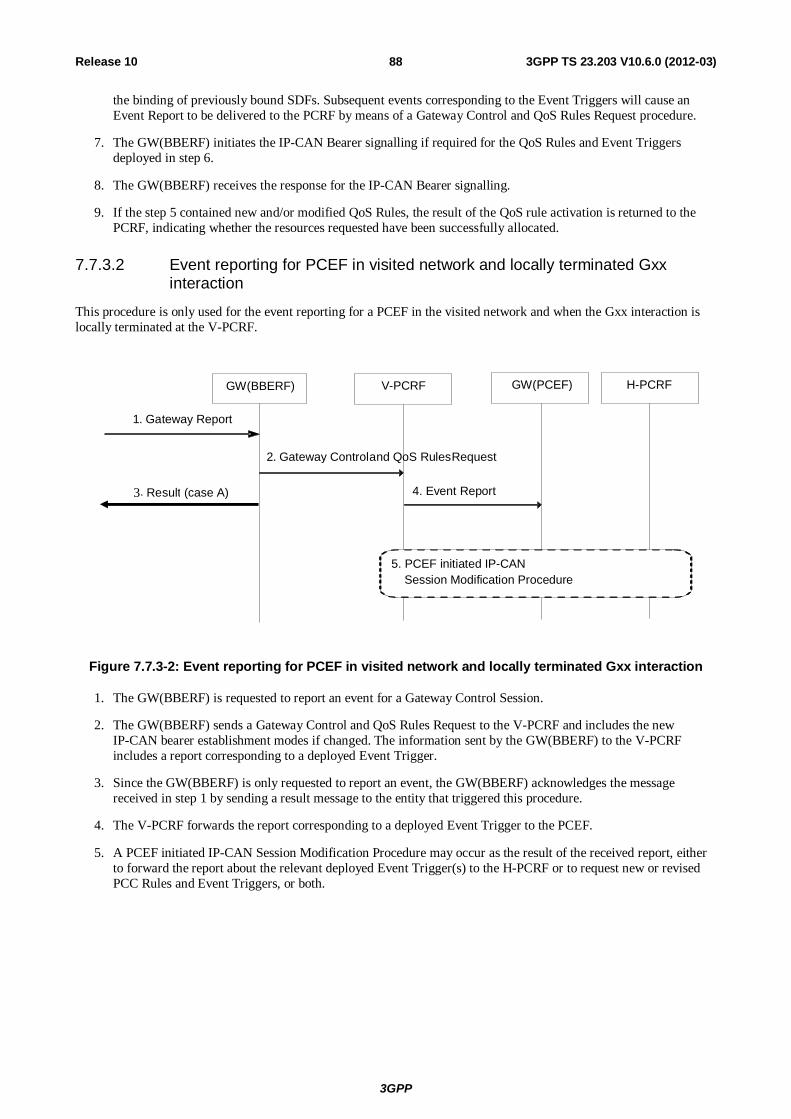
3GPP
3GPP TS 23.203 V10.6.0 (2012-03) 88Release 10
the binding of previously bound SDFs. Subsequent events corresponding to the Event Triggers will cause an Event Report to be delivered to the PCRF by means of a Gateway Control and QoS Rules Request procedure.
7. The GW(BBERF) initiates the IP-CAN Bearer signalling if required for the QoS Rules and Event Triggers deployed in step 6.
8. The GW(BBERF) receives the response for the IP-CAN Bearer signalling.
9. If the step 5 contained new and/or modified QoS Rules, the result of the QoS rule activation is returned to the PCRF, indicating whether the resources requested have been successfully allocated.
7.7.3.2 Event reporting for PCEF in visited network and locally terminated Gxx interaction
This procedure is only used for the event reporting for a PCEF in the visited network and when the Gxx interaction is locally terminated at the V-PCRF.
GW(BBERF) V -PCRF GW(PCEF)
1. Gateway Report
2. Gateway Control and QoS Rules Request
H-PCRF
5. PCEF initiated IP-CAN Session Modification Procedure
3. Result (case A) 4. Event Report
Figure 7.7.3-2: Event reporting for PCEF in visited network and locally terminated Gxx interaction
1. The GW(BBERF) is requested to report an event for a Gateway Control Session.
2. The GW(BBERF) sends a Gateway Control and QoS Rules Request to the V-PCRF and includes the new IP-CAN bearer establishment modes if changed. The information sent by the GW(BBERF) to the V-PCRF includes a report corresponding to a deployed Event Trigger.
3. Since the GW(BBERF) is only requested to report an event, the GW(BBERF) acknowledges the message received in step 1 by sending a result message to the entity that triggered this procedure.
4. The V-PCRF forwards the report corresponding to a deployed Event Trigger to the PCEF.
5. A PCEF initiated IP-CAN Session Modification Procedure may occur as the result of the received report, either to forward the report about the relevant deployed Event Trigger(s) to the H-PCRF or to request new or revised PCC Rules and Event Triggers, or both.
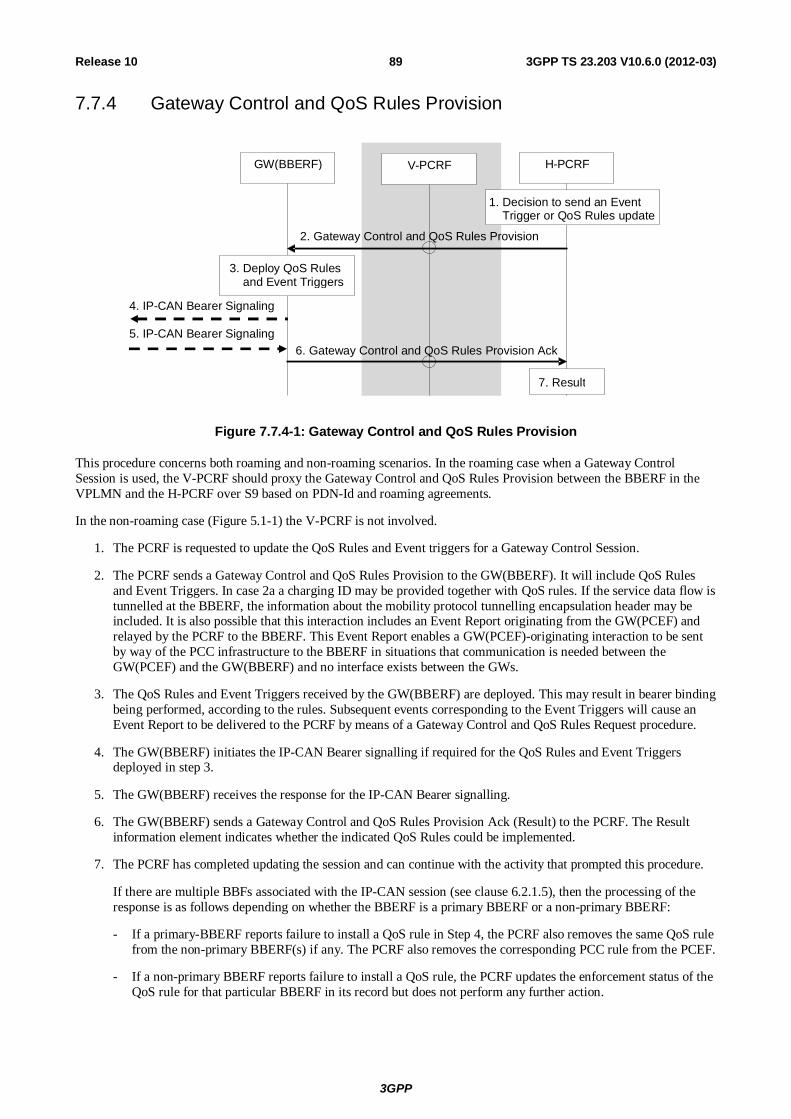
3GPP
3GPP TS 23.203 V10.6.0 (2012-03) 89Release 10
7.7.4 Gateway Control and QoS Rules Provision
GW(BBERF) V -PCRF H- PCRF
3. Deploy QoS Rules and Event Triggers
2. Gateway Control and QoS Rules Provision
6. Gateway Control and QoS Rules Provision Ack
1. Decision to send an Event Trigger or QoS Rules update
7. Result
4. IP-CAN Bearer Signaling
5. IP-CAN Bearer Signaling
Figure 7.7.4-1: Gateway Control and QoS Rules Provision
This procedure concerns both roaming and non-roaming scenarios. In the roaming case when a Gateway Control Session is used, the V-PCRF should proxy the Gateway Control and QoS Rules Provision between the BBERF in the VPLMN and the H-PCRF over S9 based on PDN-Id and roaming agreements.
In the non-roaming case (Figure 5.1-1) the V-PCRF is not involved.
1. The PCRF is requested to update the QoS Rules and Event triggers for a Gateway Control Session.
2. The PCRF sends a Gateway Control and QoS Rules Provision to the GW(BBERF). It will include QoS Rules and Event Triggers. In case 2a a charging ID may be provided together with QoS rules. If the service data flow is tunnelled at the BBERF, the information about the mobility protocol tunnelling encapsulation header may be included. It is also possible that this interaction includes an Event Report originating from the GW(PCEF) and relayed by the PCRF to the BBERF. This Event Report enables a GW(PCEF)-originating interaction to be sent by way of the PCC infrastructure to the BBERF in situations that communication is needed between the GW(PCEF) and the GW(BBERF) and no interface exists between the GWs.
3. The QoS Rules and Event Triggers received by the GW(BBERF) are deployed. This may result in bearer binding being performed, according to the rules. Subsequent events corresponding to the Event Triggers will cause an Event Report to be delivered to the PCRF by means of a Gateway Control and QoS Rules Request procedure.
4. The GW(BBERF) initiates the IP-CAN Bearer signalling if required for the QoS Rules and Event Triggers deployed in step 3.
5. The GW(BBERF) receives the response for the IP-CAN Bearer signalling.
6. The GW(BBERF) sends a Gateway Control and QoS Rules Provision Ack (Result) to the PCRF. The Result information element indicates whether the indicated QoS Rules could be implemented.
7. The PCRF has completed updating the session and can continue with the activity that prompted this procedure.
If there are multiple BBFs associated with the IP-CAN session (see clause 6.2.1.5), then the processing of the response is as follows depending on whether the BBERF is a primary BBERF or a non-primary BBERF:
- If a primary-BBERF reports failure to install a QoS rule in Step 4, the PCRF also removes the same QoS rule from the non-primary BBERF(s) if any. The PCRF also removes the corresponding PCC rule from the PCEF.
- If a non-primary BBERF reports failure to install a QoS rule, the PCRF updates the enforcement status of the QoS rule for that particular BBERF in its record but does not perform any further action.
3GPP
3GPP TS 23.203 V10.6.0 (2012-03) 90Release 10
7.7.5 Void
7.8 Change in subscription for MPS priority services Once the PCRF receives a notification of a change in MPS EPS Priority, MPS Priority Level and/or IMS Signalling Priority from the SPR, the PCRF shall make the corresponding policy decisions (i.e. ARP and/or QCI change) and initiates the necessary IP-CAN session modification procedure(s) to apply the change.
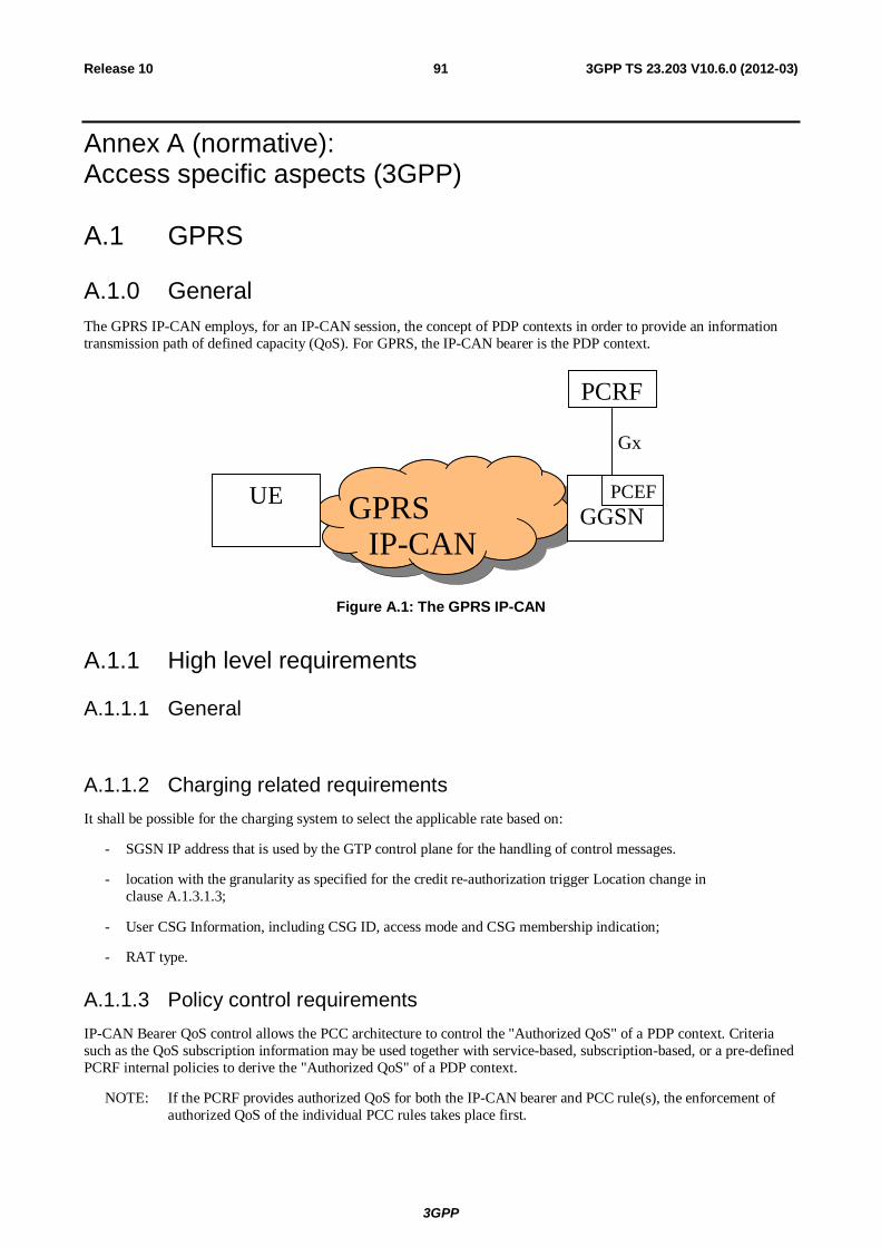
3GPP
3GPP TS 23.203 V10.6.0 (2012-03) 91Release 10
Annex A (normative): Access specific aspects (3GPP)
A.1 GPRS
A.1.0 General The GPRS IP-CAN employs, for an IP-CAN session, the concept of PDP contexts in order to provide an information transmission path of defined capacity (QoS). For GPRS, the IP-CAN bearer is the PDP context.
GPRS
IP-CAN
GGSN PCEF
PCRF
Gx
UE
Figure A.1: The GPRS IP-CAN
A.1.1 High level requirements
A.1.1.1 General
A.1.1.2 Charging related requirements It shall be possible for the charging system to select the applicable rate based on:
- SGSN IP address that is used by the GTP control plane for the handling of control messages.
- location with the granularity as specified for the credit re-authorization trigger Location change in clause A.1.3.1.3;
- User CSG Information, including CSG ID, access mode and CSG membership indication;
- RAT type.
A.1.1.3 Policy control requirements IP-CAN Bearer QoS control allows the PCC architecture to control the "Authorized QoS" of a PDP context. Criteria such as the QoS subscription information may be used together with service-based, subscription-based, or a pre-defined PCRF internal policies to derive the "Authorized QoS" of a PDP context.
NOTE: If the PCRF provides authorized QoS for both the IP-CAN bearer and PCC rule(s), the enforcement of authorized QoS of the individual PCC rules takes place first.
3GPP
3GPP TS 23.203 V10.6.0 (2012-03) 92Release 10
A.1.1.4 QoS control For GPRS IP-CANs it shall be possible to apply QoS control at APN-level.
QoS control per APN allows the PCC architecture to control the authorized APN-AMBR to be enforced for the total bandwidth usage of non-GBR QCIs at the PCEF within the same APN.
The PCRF should not authorize the MBR/APN-AMBR exceeding the maximum MBR/APN-AMBR given by PCEF.
NOTE 1: The maximum MBR/APN-AMBR indicates the maximum bit rate acceptable by the UE or by the VPLMN.
NOTE 2: For the enforcement of the APN-AMBR for all IP-CAN sessions to the same APN, the IP-CAN is required to select the same PCEF for all of them.
A.1.2 Architecture model and reference points
A.1.2.1 Reference points
A.1.2.1.1 Gx reference point
The Gx reference point enables the signalling of PCC rules, which govern the PCC behaviour, and it supports the following GPRS-specific functions:
- Indication of PDP context activation, modification and deactivation.
A.1.2.2 Reference architecture In the GPRS IP-CAN, the Bearer Binding and Event Reporting Function (BBERF) does not apply.
A.1.3 Functional description
A.1.3.1 Overall description
A.1.3.1.1 Binding mechanism
A.1.3.1.1.0 General
As explained in clause 6.1.1, the binding mechanism is performed in three different steps: session binding, PCC rule authorization and bearer binding. Session binding has no GPRS specifics.
For the GPRS case bearer binding is performed by:
- PCRF, when the selected operation mode is UE-only, see TS 23.060 [12], either due to PCRF decision or network/UE capability;
- PCRF and PCEF (i.e. the PCRF performs the binding of the PCC rules for user controlled services while the PCEF performs the binding of the PCC rules for the network controlled services), when the selected operation mode is UE/NW.
The bearer binding performed by the PCRF shall bind a PCC rule that is authorized for a TFT packet filter to the PDP context the TFT packet filter has been assigned by the UE if the PCC rule can be authorized for the QCI of the PDP context. If a new PDP context is established, the PCRF can also bind PCC rule(s) to the PDP context if the QCI of the PDP context is different from the QCI, the PCC rule(s) can be authorized for since the PCRF can modify the QCI of the new PDP context. The binding mechanism shall comply with the established traffic flow template (TFT) packet filters (for the whole IP-CAN session).
3GPP
3GPP TS 23.203 V10.6.0 (2012-03) 93Release 10
The bearer binding performed by the PCEF shall compare the PCC rule QoS parameters with the PDP context QoS parameters and bind a PCC rule:
- to a candidate PDP context with a matching QoS class and Evolved ARP (if this is supported by the SGSN);
- to a candidate PDP context with a matching QoS class and Evolved ARP (if this is supported by the SGSN) that, after modification of the bitrates, fulfils the PCC rule QoS demands;
- to a new PDP context with a matching QoS class and Evolved ARP (if this is supported by the SGSN), if there is no suitable candidate PDP context present.
The bearer binding mechanism associates the PCC rule with the PDP context to carry the service data flow. The association shall:
- cause the downlink part of the service data flow to be directed to the PDP context in the association, and
- assume that the UE directs the uplink part of the service data flow to the PDP context in the association.
Thus, the detection of the uplink part of a service data flow shall be active on the PDP context, which the downlink packets of the same service data flow is directed to. The detection of the uplink part of the service data flow may be active, in parallel, on any number of additional PDP contexts.
A.1.3.1.1.1 Bearer binding mechanism allocated to the PCEF
When the bearer binding mechanism is allocated to the PCEF, no per bearer information is required to be communicated over the Gx reference point.
Once the PCRF has provided the PCC rule decisions at the IP-CAN session establishment procedure, the PCRF shall provide further PCC rule decisions
- using the PCRF initiated IP-CAN Session Modification procedure; or
- in response to an event report from the PCEF (the GW(PCEF) initiated IP-CAN Session Modification).
The bearer binding function shall not combine PCC rules with different ARP values onto the same PDP context.
NOTE: If Evolved ARP is not supported by the SGSN then this enables a modification of the PDP context ARP without impacting the bearer binding after relocation to a SGSN that supports Evolved ARP.
A.1.3.1.1.2 Bearer binding mechanism allocated to the PCRF
If a PDP context is established/modified in order to successfully perform the bearer binding the PCRF will set the PCC rule as binding-pending status until the PCEF reports the establishment or modification of a PDP context that fulfils the PCC rule demands or the PCC rule is removed.
The following particularities apply when the bearer binding mechanism is allocated to the PCRF:
- The PCEF
- shall include a bearer reference in all requests for PCC decisions;
- shall report bearer QoS class identifier and the associated bitrates for new/modified PDP contexts;
- shall report the TFT filter status for new PDP contexts and for modified TFTs;
- shall report the deactivation of a PDP context
- The PCRF
- shall provide the bearer reference for the binding result when activating a PCC rule;
- shall arm the GPRS-specific IP-CAN event trigger "PDP context activity".
- shall arm the event trigger "traffic mapping information change".
3GPP
3GPP TS 23.203 V10.6.0 (2012-03) 94Release 10
NOTE: For the above case, the allocation of the bearer binding mechanism to the PCRF facilitates the migration from Rel-6 products to Rel-7 products. The allocation of the binding mechanism may be re-evaluated in future releases.
When the PCRF performs the bearer binding the ARP information in the PCC rule shall be ignored unless the SGSN has indicated support for Evolved ARP.
A.1.3.1.2 Reporting
A container may be closed and a new container opened by the triggering of event triggers.
A.1.3.1.3 Credit management
For GPRS the PCEF shall initiate one credit management session for each PDP context.
For GPRS the credit re-authorisation triggers in table A.1 shall apply in addition to the ones in table 6.1.
Table A.1: GPRS specific credit re-authorization triggers
Credit re-authorization trigger Description SGSN change The UE has moved to a new SGSN. RAT type change. The characteristics of the air interface, communicated as the radio access
type, has changed. Location change (routeing area) The routeing area of the UE has changed. Location change (CGI/SAI) The CGI/SAI of the UE has changed. User CSG Information change in CSG cell
User CSG Information has changed when the UE enters/leaves/accesses via a CSG cell
User CSG Information change in subscribed hybrid cell
User CSG Information has changed when the UE enters/leaves/accesses via a hybrid cell in which the subscriber is a CSG member
User CSG Information change in un-subscribed hybrid cell (see note)
User CSG Information has changed when the UE enters/leaves/accesses via a hybrid cell in which the subscriber is not a CSG member
NOTE: Due to the increased signalling load, such reporting should be applied for a limited number of subscribers only.
If the Location change trigger for CGI / SAI or RAI is armed, the GGSN should request the SGSN to report any changes in location to the level indicated by the trigger according to the procedures described in TS 23.060 [12]. If credit-authorization triggers and event triggers require different levels of reporting of location change for different PDP contexts for a single UE, the SGSN reports location changes to the highest level of detail required. However, the GGSN should not trigger a credit re-authorization if the report received is more detailed than requested by the OCS.
If the User CSG Information change in CSG cell trigger is armed, the GGSN should request the SGSN to report any changes in user CSG information when the UE enters/leaves/accesses via a CSG cell.
If the User CSG Information change in subscribed hybrid cell trigger is armed, the GGSN should request the SGSN to report any changes in user CSG information when the UE enters/leaves/accesses via a hybrid cell in which the subscriber is a CSG member.
If the User CSG Information change in un-subscribed hybrid cell trigger is armed, the GGSN should request the SGSN to report any changes in user CSG information when the UE enters/leaves/accesses via a hybrid cell in which the subscriber is not a CSG member.
If credit-authorization triggers and event triggers require different levels of reporting of User CSG information for a single UE, the User CSG information to be reported should be changed to the highest level of detail required.
A.1.3.1.4 Event Triggers
For GPRS the event triggers in table A.2 shall apply in addition to the ones in table 6.2.
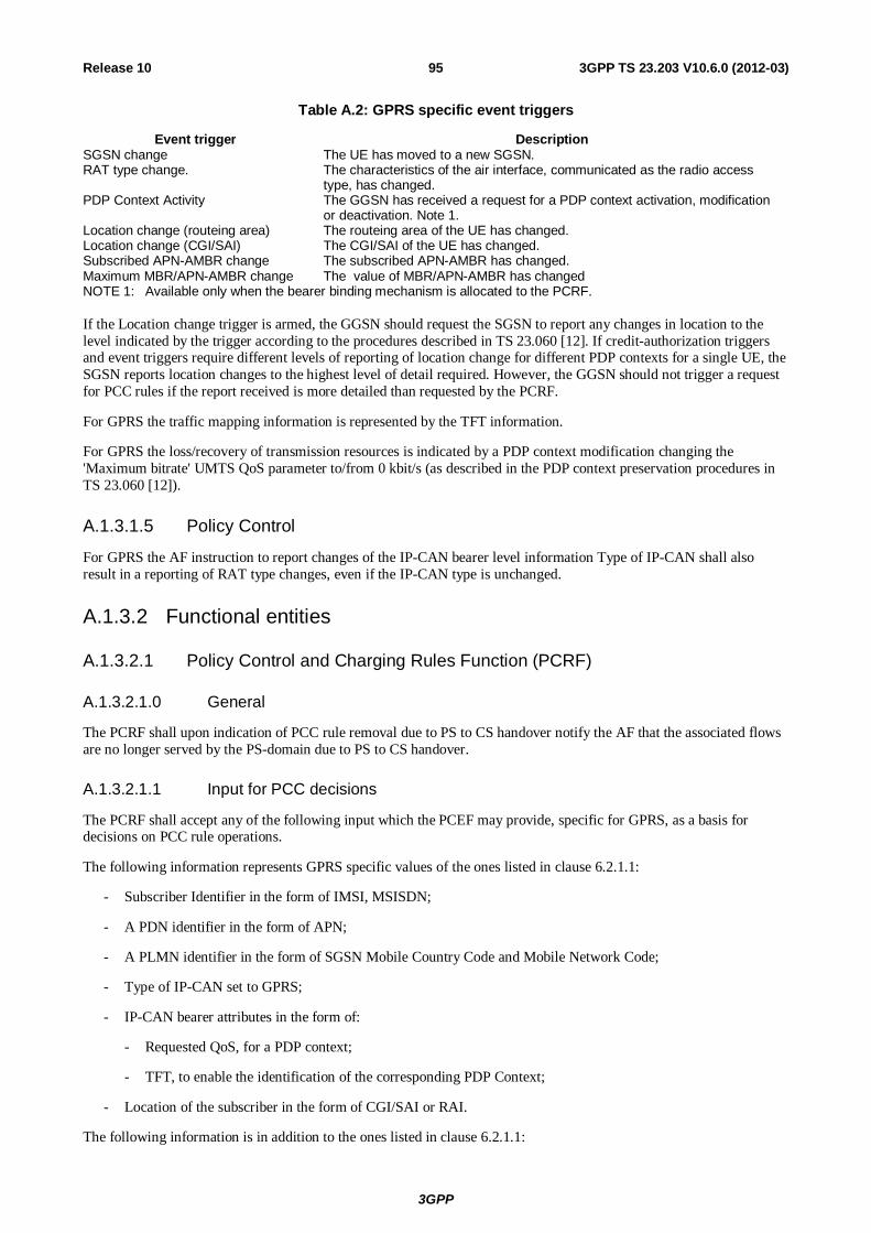
3GPP
3GPP TS 23.203 V10.6.0 (2012-03) 95Release 10
Table A.2: GPRS specific event triggers
Event trigger Description SGSN change The UE has moved to a new SGSN. RAT type change. The characteristics of the air interface, communicated as the radio access
type, has changed. PDP Context Activity The GGSN has received a request for a PDP context activation, modification
or deactivation. Note 1. Location change (routeing area) The routeing area of the UE has changed. Location change (CGI/SAI) The CGI/SAI of the UE has changed. Subscribed APN-AMBR change The subscribed APN-AMBR has changed. Maximum MBR/APN-AMBR change The value of MBR/APN-AMBR has changed NOTE 1: Available only when the bearer binding mechanism is allocated to the PCRF. If the Location change trigger is armed, the GGSN should request the SGSN to report any changes in location to the level indicated by the trigger according to the procedures described in TS 23.060 [12]. If credit-authorization triggers and event triggers require different levels of reporting of location change for different PDP contexts for a single UE, the SGSN reports location changes to the highest level of detail required. However, the GGSN should not trigger a request for PCC rules if the report received is more detailed than requested by the PCRF.
For GPRS the traffic mapping information is represented by the TFT information.
For GPRS the loss/recovery of transmission resources is indicated by a PDP context modification changing the 'Maximum bitrate' UMTS QoS parameter to/from 0 kbit/s (as described in the PDP context preservation procedures in TS 23.060 [12]).
A.1.3.1.5 Policy Control
For GPRS the AF instruction to report changes of the IP-CAN bearer level information Type of IP-CAN shall also result in a reporting of RAT type changes, even if the IP-CAN type is unchanged.
A.1.3.2 Functional entities
A.1.3.2.1 Policy Control and Charging Rules Function (PCRF)
A.1.3.2.1.0 General
The PCRF shall upon indication of PCC rule removal due to PS to CS handover notify the AF that the associated flows are no longer served by the PS-domain due to PS to CS handover.
A.1.3.2.1.1 Input for PCC decisions
The PCRF shall accept any of the following input which the PCEF may provide, specific for GPRS, as a basis for decisions on PCC rule operations.
The following information represents GPRS specific values of the ones listed in clause 6.2.1.1:
- Subscriber Identifier in the form of IMSI, MSISDN;
- A PDN identifier in the form of APN;
- A PLMN identifier in the form of SGSN Mobile Country Code and Mobile Network Code;
- Type of IP-CAN set to GPRS;
- IP-CAN bearer attributes in the form of:
- Requested QoS, for a PDP context;
- TFT, to enable the identification of the corresponding PDP Context;
- Location of the subscriber in the form of CGI/SAI or RAI.
The following information is in addition to the ones listed in clause 6.2.1.1:
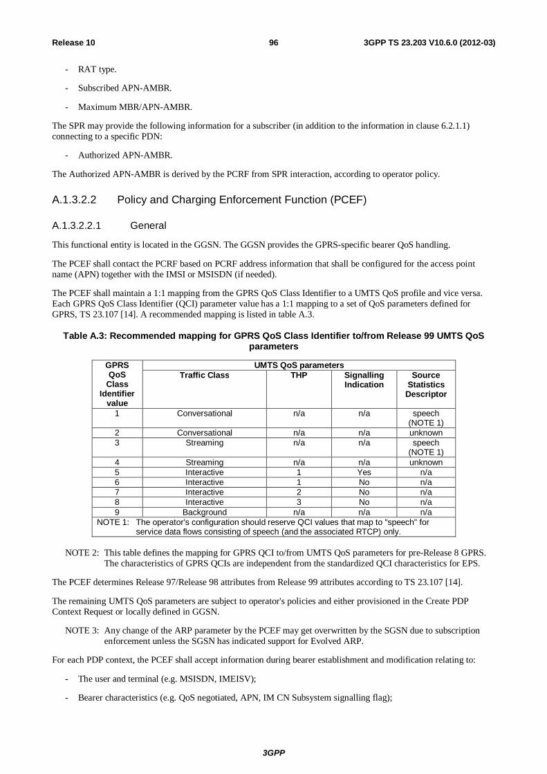
3GPP
3GPP TS 23.203 V10.6.0 (2012-03) 96Release 10
- RAT type.
- Subscribed APN-AMBR.
- Maximum MBR/APN-AMBR.
The SPR may provide the following information for a subscriber (in addition to the information in clause 6.2.1.1) connecting to a specific PDN:
- Authorized APN-AMBR.
The Authorized APN-AMBR is derived by the PCRF from SPR interaction, according to operator policy.
A.1.3.2.2 Policy and Charging Enforcement Function (PCEF)
A.1.3.2.2.1 General
This functional entity is located in the GGSN. The GGSN provides the GPRS-specific bearer QoS handling.
The PCEF shall contact the PCRF based on PCRF address information that shall be configured for the access point name (APN) together with the IMSI or MSISDN (if needed).
The PCEF shall maintain a 1:1 mapping from the GPRS QoS Class Identifier to a UMTS QoS profile and vice versa. Each GPRS QoS Class Identifier (QCI) parameter value has a 1:1 mapping to a set of QoS parameters defined for GPRS, TS 23.107 [14]. A recommended mapping is listed in table A.3.
Table A.3: Recommended mapping for GPRS QoS Class Identifier to/from Release 99 UMTS QoS parameters
GPRS QoS
Class Identifier
value
UMTS QoS parameters Traffic Class THP Signalling
Indication Source
Statistics Descriptor
1 Conversational n/a n/a speech (NOTE 1)
2 Conversational n/a n/a unknown 3 Streaming n/a n/a speech
(NOTE 1) 4 Streaming n/a n/a unknown 5 Interactive 1 Yes n/a 6 Interactive 1 No n/a 7 Interactive 2 No n/a 8 Interactive 3 No n/a 9 Background n/a n/a n/a
NOTE 1: The operator's configuration should reserve QCI values that map to "speech" for service data flows consisting of speech (and the associated RTCP) only.
NOTE 2: This table defines the mapping for GPRS QCI to/from UMTS QoS parameters for pre-Release 8 GPRS.
The characteristics of GPRS QCIs are independent from the standardized QCI characteristics for EPS.
The PCEF determines Release 97/Release 98 attributes from Release 99 attributes according to TS 23.107 [14].
The remaining UMTS QoS parameters are subject to operator's policies and either provisioned in the Create PDP Context Request or locally defined in GGSN.
NOTE 3: Any change of the ARP parameter by the PCEF may get overwritten by the SGSN due to subscription enforcement unless the SGSN has indicated support for Evolved ARP.
For each PDP context, the PCEF shall accept information during bearer establishment and modification relating to:
- The user and terminal (e.g. MSISDN, IMEISV);
- Bearer characteristics (e.g. QoS negotiated, APN, IM CN Subsystem signalling flag);
3GPP
3GPP TS 23.203 V10.6.0 (2012-03) 97Release 10
- Network related information (e.g. MCC and MNC).
The PCEF shall use this information in the OCS request/reporting or request for PCC rules.
A GGSN may provide more than one APN for access to the same PDN. It should be possible to enable or disable PCC functionality for each APN, independent from the other APNs for access to the same PDN. Once the PCC functionality is disabled, regular GPRS charging and policy methods would be applied, i.e. no PCRF interaction would occur.
For each PDP context, there shall be a separate OCS request/OFCS reporting, so this allows the OCS and offline charging system to apply different rating depending on the PDP context.
The GGSN shall report the service data flow based charging data on a per PDP context basis.
The GGSN shall be able to request the SGSN to provide reports of changes in CGI/SAI/RAI of a UE as directed by the credit re-authorization triggers and/or event triggers.
The PCEF enforces QoS Policies as indicated by the PCRF in accordance to what is stated in clause 6.2.2.1 with the following additions:
- Authorized APN-AMBR enforcement. The PCEF shall enforce the authorized APN-AMBR received via the Gx interface for the total bandwidth usage of non-GBR QCI for the APN.
Only the GBR per bearer is used for resource reservation (e.g. admission control in the RAN).
The MBR (per PCC rule / per bearer) and the authorized APN-AMBR are used for rate policing.
When the GGSN is connected to a SGSN that does not support the Evolved ARP, the GGSN shall map the Evolved ARP to Rel-99 ARP parameter value as specified in Annex E of TS 23.401 [17].
A.1.3.2.2.2 Service data flow detection
For uplink traffic, in the case of GPRS, all the uplink parts of service data flows templates, which are associated with the PDP context are candidates for matching in the detection process.
NOTE: Service data flow templates, which are not associated with the PDP context the packet was received, are not candidates for matching (dashed in the figure).
A.1.3.2.2.3 Packet Routeing and Transfer Function
The PCEF performs the packet routeing and transfer functions as specified in TS 23.060 [12], with the differences specified in this clause.
For the PDP address of an UE, the PCEF routes downlink packets to the different PDP contexts based on the downlink parts of the service data flow templates, in the active PCC rules and their routeing associations to the PDP contexts. The association between an active PCC rule and a PDP context shall correspond to the downlink TFT received from the UE. Each active PCC rule shall have a single routeing association to a PDP context. Upon reception of a packet, the PCEF evaluates the downlink part of the service data flow templates of the PCC rules activated for the PDP address in order of precedence to find a match. When the first match is found, the packet is tunnelled to the SGSN via the PDP context, for which the PCC rule has the routeing association. If no match is found, the PCEF shall silently discard the packet.
The UE shall define TFTs that enable successful binding at the PCRF for service data flows requiring a binding to occur.
For each uplink packet, the UE should choose the PDP context that is used for the downlink direction of the same service data flow, as declared in the TFT information. The PCEF shall only apply the uplink parts of the service data flow templates of the PCC rules, which are associated with the same PDP context as the uplink packet arrived on.
The packet filters, to be applied on dedicated signalling PDP contexts, shall form PCC rules, which shall be granted higher precedence than any other PCC rule and be active on the dedicated signalling context.
A.1.3.2.2.4 Measurement
The details of measurement are specified in TS 32.251 [9].
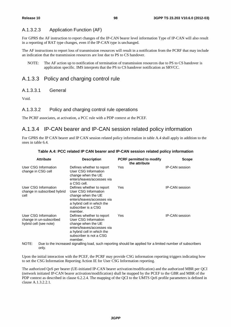
3GPP
3GPP TS 23.203 V10.6.0 (2012-03) 98Release 10
A.1.3.2.3 Application Function (AF)
For GPRS the AF instruction to report changes of the IP-CAN bearer level information Type of IP-CAN will also result in a reporting of RAT type changes, even if the IP-CAN type is unchanged.
The AF instructions to report loss of transmission resources will result in a notification from the PCRF that may include an indication that the transmission resources are lost due to PS to CS handover.
NOTE: The AF action up to notification of termination of transmission resources due to PS to CS handover is application specific. IMS interprets that the PS to CS handover notification as SRVCC.
A.1.3.3 Policy and charging control rule
A.1.3.3.1 General
Void.
A.1.3.3.2 Policy and charging control rule operations
The PCRF associates, at activation, a PCC rule with a PDP context at the PCEF.
A.1.3.4 IP-CAN bearer and IP-CAN session related policy information For GPRS the IP CAN bearer and IP CAN session related policy information in table A.4 shall apply in addition to the ones in table 6.4.
Table A.4: PCC related IP CAN bearer and IP-CAN session related policy information
Attribute Description PCRF permitted to modify the attribute
Scope
User CSG Information change in CSG cell
Defines whether to report User CSG Information change when the UE enters/leaves/accesses via a CSG cell.
Yes IP-CAN session
User CSG Information change in subscribed hybrid cell
Defines whether to report User CSG Information change when the UE enters/leaves/accesses via a hybrid cell in which the subscriber is a CSG member.
Yes IP-CAN session
User CSG Information change in un-subscribed hybrid cell (see note)
Defines whether to report User CSG Information change when the UE enters/leaves/accesses via a hybrid cell in which the subscriber is not a CSG member.
Yes IP-CAN session
NOTE: Due to the increased signalling load, such reporting should be applied for a limited number of subscribers only.
Upon the initial interaction with the PCEF, the PCRF may provide CSG information reporting triggers indicating how to set the CSG Information Reporting Action IE for User CSG Information reporting.
The authorized QoS per bearer (UE-initiated IP-CAN bearer activation/modification) and the authorized MBR per QCI (network initiated IP-CAN bearer activation/modification) shall be mapped by the PCEF to the GBR and MBR of the PDP context as described in clause 6.2.2.4. The mapping of the QCI to the UMTS QoS profile parameters is defined in clause A.1.3.2.2.1.
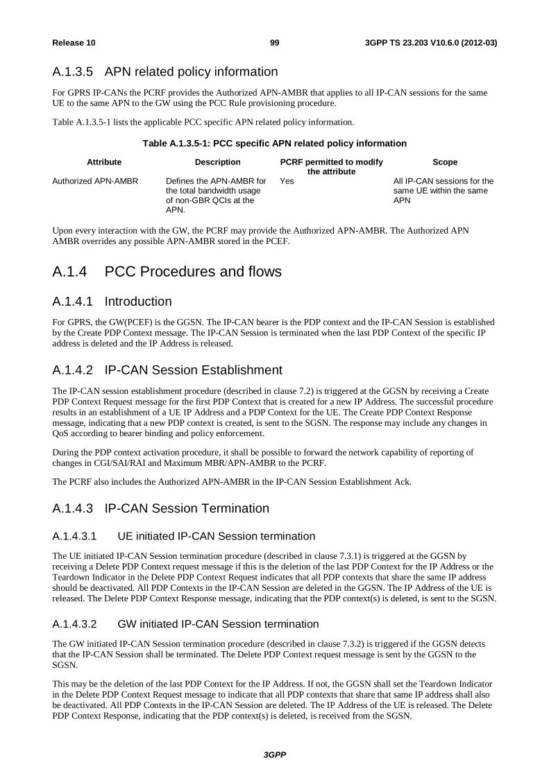
3GPP
3GPP TS 23.203 V10.6.0 (2012-03) 99Release 10
A.1.3.5 APN related policy information For GPRS IP-CANs the PCRF provides the Authorized APN-AMBR that applies to all IP-CAN sessions for the same UE to the same APN to the GW using the PCC Rule provisioning procedure.
Table A.1.3.5-1 lists the applicable PCC specific APN related policy information.
Table A.1.3.5-1: PCC specific APN related policy information
Attribute Description PCRF permitted to modify the attribute
Scope
Authorized APN-AMBR Defines the APN-AMBR for the total bandwidth usage of non-GBR QCIs at the APN.
Yes All IP-CAN sessions for the same UE within the same APN
Upon every interaction with the GW, the PCRF may provide the Authorized APN-AMBR. The Authorized APN AMBR overrides any possible APN-AMBR stored in the PCEF.
A.1.4 PCC Procedures and flows
A.1.4.1 Introduction For GPRS, the GW(PCEF) is the GGSN. The IP-CAN bearer is the PDP context and the IP-CAN Session is established by the Create PDP Context message. The IP-CAN Session is terminated when the last PDP Context of the specific IP address is deleted and the IP Address is released.
A.1.4.2 IP-CAN Session Establishment The IP-CAN session establishment procedure (described in clause 7.2) is triggered at the GGSN by receiving a Create PDP Context Request message for the first PDP Context that is created for a new IP Address. The successful procedure results in an establishment of a UE IP Address and a PDP Context for the UE. The Create PDP Context Response message, indicating that a new PDP context is created, is sent to the SGSN. The response may include any changes in QoS according to bearer binding and policy enforcement.
During the PDP context activation procedure, it shall be possible to forward the network capability of reporting of changes in CGI/SAI/RAI and Maximum MBR/APN-AMBR to the PCRF.
The PCRF also includes the Authorized APN-AMBR in the IP-CAN Session Establishment Ack.
A.1.4.3 IP-CAN Session Termination
A.1.4.3.1 UE initiated IP-CAN Session termination
The UE initiated IP-CAN Session termination procedure (described in clause 7.3.1) is triggered at the GGSN by receiving a Delete PDP Context request message if this is the deletion of the last PDP Context for the IP Address or the Teardown Indicator in the Delete PDP Context Request indicates that all PDP contexts that share the same IP address should be deactivated. All PDP Contexts in the IP-CAN Session are deleted in the GGSN. The IP Address of the UE is released. The Delete PDP Context Response message, indicating that the PDP context(s) is deleted, is sent to the SGSN.
A.1.4.3.2 GW initiated IP-CAN Session termination
The GW initiated IP-CAN Session termination procedure (described in clause 7.3.2) is triggered if the GGSN detects that the IP-CAN Session shall be terminated. The Delete PDP Context request message is sent by the GGSN to the SGSN.
This may be the deletion of the last PDP Context for the IP Address. If not, the GGSN shall set the Teardown Indicator in the Delete PDP Context Request message to indicate that all PDP contexts that share that same IP address shall also be deactivated. All PDP Contexts in the IP-CAN Session are deleted. The IP Address of the UE is released. The Delete PDP Context Response, indicating that the PDP context(s) is deleted, is received from the SGSN.
3GPP
3GPP TS 23.203 V10.6.0 (2012-03) 100Release 10
A.1.4.4 IP-CAN Session Modification
A.1.4.4.1 IP-CAN Session Modification; GW(PCEF) initiated
The GW(PCEF) initiated IP-CAN Session modification procedure (described in clause 7.4.1) is triggered at the GGSN by receiving one of the following messages:
- Create PDP Context Request message;
- Update PDP Context Request message;
- Delete PDP Context Request message;
- a Change Notification message (indicating the new CGI, SAI or RAI) – see TS 23.060 [12].
In case of a Create PDP Context Request message, the modification of the IP-CAN Session is the addition of a new PDP Context to the IP-CAN Session. The new PDP Context is added with specific QoS requirements and traffic mapping information (TFT). A Create PDP Context Response message, indicating that a new PDP context is created, is sent to the SGSN. The response may include any changes in QoS according to bearer binding and policy enforcement.
In case of an Update PDP Context Request, a PDP Context in the IP-CAN Session is modified. The modification may include modifying the QoS and/or the traffic mapping information. The Update PDP Context Response message, indicating that a PDP context is modified, is sent to the SGSN. The response may include any changes in QoS according to bearer binding and policy enforcement.
In case of a Delete PDP Context Request message, a PDP Context in the IP-CAN Session is deleted. The Delete PDP Context Response message, indicating that a PDP context is deleted, is sent to the SGSN. If the PS to CS handover indicator is set in a Delete PDP context request message , the PCEF reports termination of transmission resources for associated PCC Rules due to PS to CS handover.
A Change Notification message indicating a change in CGI / SAI or RAI information is received when there are only changes regarding the current location of the UE. A change in CGI / SAI or RAI may also be notified within other session management messages.
The PCRF may provide the Authorized APN-AMBR in the Acknowledgement of the IP-CAN Session Modification to the GW (in addition to the parameters in clause 7.4.1).
Based on operator policy and Maximum MBR/APN-AMBR the PCRF may re-authorize MBR/APN-AMBR.
A.1.4.4.2 IP-CAN Session Modification; PCRF initiated
The PCRF initiated IP-CAN Session modification procedure (described in clause 7.4.2) may result in a GGSN initiated PDP Context Modification or Deactivation or a Network Requested secondary PDP Context Activation.
If a PDP Context in the IP-CAN Session needs to be modified, the GGSN sends an Update PDP Context Request message. The modification may include modifying the QoS negotiated, negotiated Evolved ARP or the required CGI/SAI/RAI change reporting. The Update PDP Context Response message, indicating that a PDP context is modified, will be received from the SGSN.
If a PDP Context in the IP-CAN Session needs to be deleted, the GGSN sends a Delete PDP Context Request message. The Delete PDP Context Response message will be received from the SGSN.
If the PCEF bearer binding yields that a new PDP context is required, the PCEF shall initiate the Network Requested secondary PDP Context Activation procedure.
NOTE: If online charging is applicable, with PCEF bearer binding and a new PDP Context is required, the PCEF may not have all the information (e.g. NSAPI and negotiated QoS) associated with that PDP context for the credit authorisation until the activation procedure is complete and therefore a second credit authorisation may be necessary to provide the remaining information.
The PCRF may provide the Authorized APN-AMBR in the Policy and Charging Rule Provision to the GW (in addition to the parameters in clause 7.4.2).
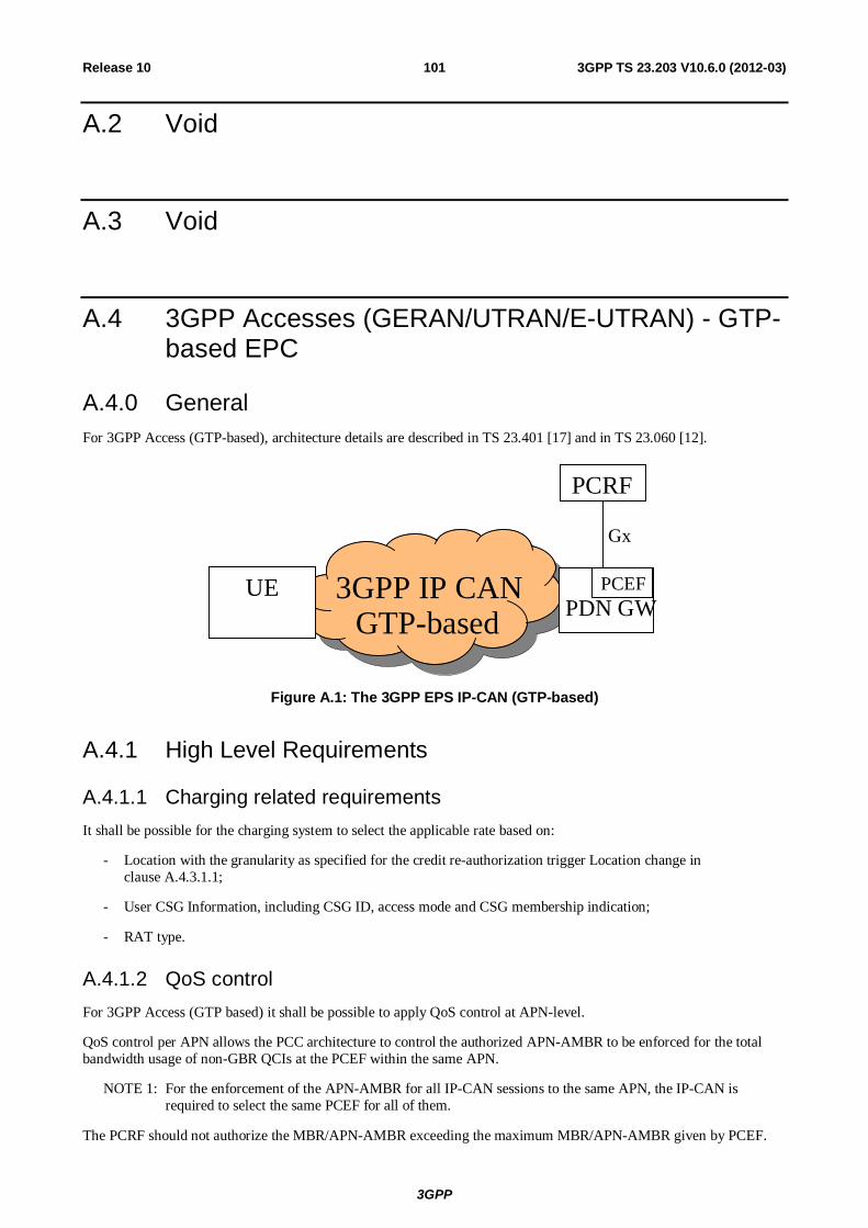
3GPP
3GPP TS 23.203 V10.6.0 (2012-03) 101Release 10
A.2 Void
A.3 Void
A.4 3GPP Accesses (GERAN/UTRAN/E-UTRAN) - GTP-based EPC
A.4.0 General For 3GPP Access (GTP-based), architecture details are described in TS 23.401 [17] and in TS 23.060 [12].
3GPP IP CAN
GTP-based PDN GW
PCEF
PCRF
Gx
UE
Figure A.1: The 3GPP EPS IP-CAN (GTP-based)
A.4.1 High Level Requirements
A.4.1.1 Charging related requirements It shall be possible for the charging system to select the applicable rate based on:
- Location with the granularity as specified for the credit re-authorization trigger Location change in clause A.4.3.1.1;
- User CSG Information, including CSG ID, access mode and CSG membership indication;
- RAT type.
A.4.1.2 QoS control For 3GPP Access (GTP based) it shall be possible to apply QoS control at APN-level.
QoS control per APN allows the PCC architecture to control the authorized APN-AMBR to be enforced for the total bandwidth usage of non-GBR QCIs at the PCEF within the same APN.
NOTE 1: For the enforcement of the APN-AMBR for all IP-CAN sessions to the same APN, the IP-CAN is required to select the same PCEF for all of them.
The PCRF should not authorize the MBR/APN-AMBR exceeding the maximum MBR/APN-AMBR given by PCEF.
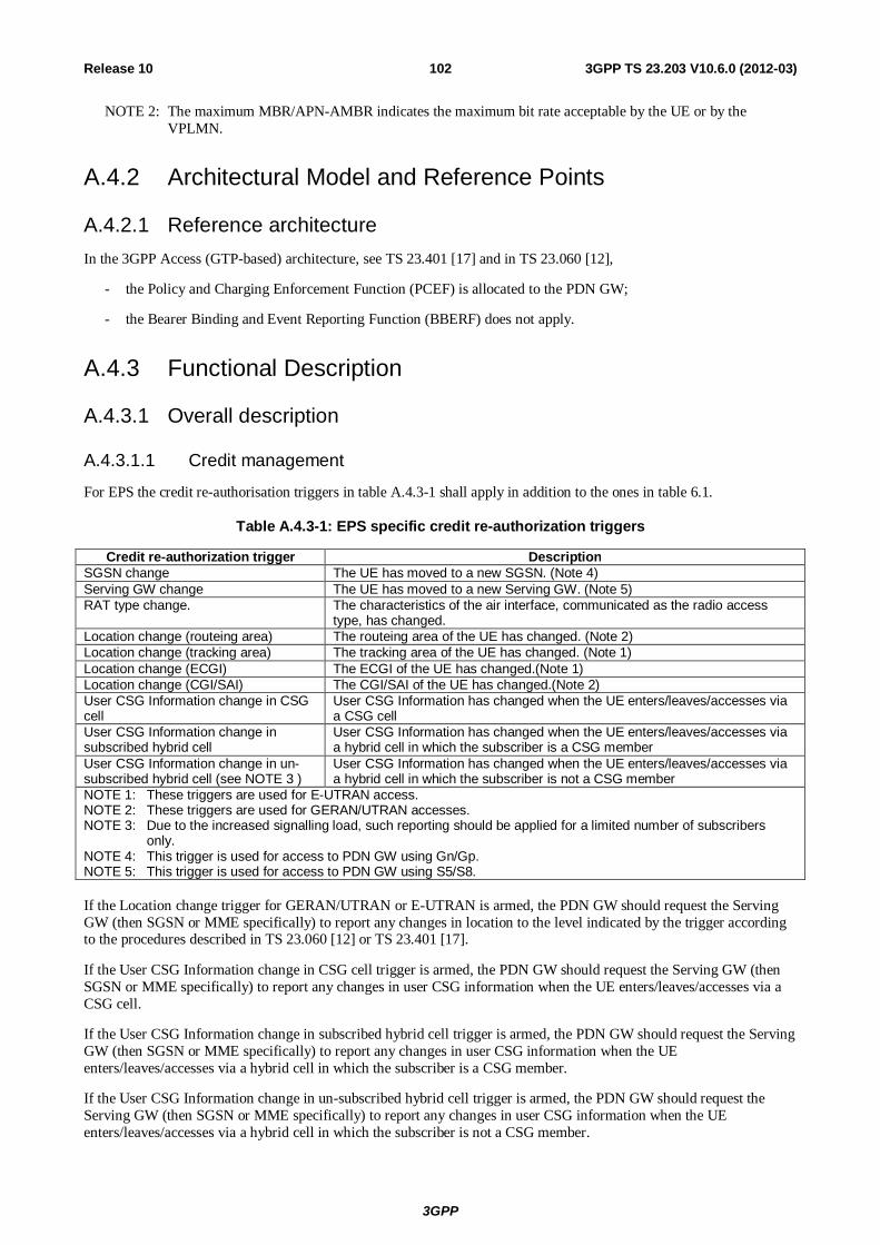
3GPP
3GPP TS 23.203 V10.6.0 (2012-03) 102Release 10
NOTE 2: The maximum MBR/APN-AMBR indicates the maximum bit rate acceptable by the UE or by the VPLMN.
A.4.2 Architectural Model and Reference Points
A.4.2.1 Reference architecture In the 3GPP Access (GTP-based) architecture, see TS 23.401 [17] and in TS 23.060 [12],
- the Policy and Charging Enforcement Function (PCEF) is allocated to the PDN GW;
- the Bearer Binding and Event Reporting Function (BBERF) does not apply.
A.4.3 Functional Description
A.4.3.1 Overall description
A.4.3.1.1 Credit management
For EPS the credit re-authorisation triggers in table A.4.3-1 shall apply in addition to the ones in table 6.1.
Table A.4.3-1: EPS specific credit re-authorization triggers
Credit re-authorization trigger Description SGSN change The UE has moved to a new SGSN. (Note 4) Serving GW change The UE has moved to a new Serving GW. (Note 5) RAT type change. The characteristics of the air interface, communicated as the radio access
type, has changed. Location change (routeing area) The routeing area of the UE has changed. (Note 2) Location change (tracking area) The tracking area of the UE has changed. (Note 1) Location change (ECGI) The ECGI of the UE has changed.(Note 1) Location change (CGI/SAI) The CGI/SAI of the UE has changed.(Note 2) User CSG Information change in CSG cell
User CSG Information has changed when the UE enters/leaves/accesses via a CSG cell
User CSG Information change in subscribed hybrid cell
User CSG Information has changed when the UE enters/leaves/accesses via a hybrid cell in which the subscriber is a CSG member
User CSG Information change in un-subscribed hybrid cell (see NOTE 3 )
User CSG Information has changed when the UE enters/leaves/accesses via a hybrid cell in which the subscriber is not a CSG member
NOTE 1: These triggers are used for E-UTRAN access. NOTE 2: These triggers are used for GERAN/UTRAN accesses. NOTE 3: Due to the increased signalling load, such reporting should be applied for a limited number of subscribers
only. NOTE 4: This trigger is used for access to PDN GW using Gn/Gp. NOTE 5: This trigger is used for access to PDN GW using S5/S8. If the Location change trigger for GERAN/UTRAN or E-UTRAN is armed, the PDN GW should request the Serving GW (then SGSN or MME specifically) to report any changes in location to the level indicated by the trigger according to the procedures described in TS 23.060 [12] or TS 23.401 [17].
If the User CSG Information change in CSG cell trigger is armed, the PDN GW should request the Serving GW (then SGSN or MME specifically) to report any changes in user CSG information when the UE enters/leaves/accesses via a CSG cell.
If the User CSG Information change in subscribed hybrid cell trigger is armed, the PDN GW should request the Serving GW (then SGSN or MME specifically) to report any changes in user CSG information when the UE enters/leaves/accesses via a hybrid cell in which the subscriber is a CSG member.
If the User CSG Information change in un-subscribed hybrid cell trigger is armed, the PDN GW should request the Serving GW (then SGSN or MME specifically) to report any changes in user CSG information when the UE enters/leaves/accesses via a hybrid cell in which the subscriber is not a CSG member.
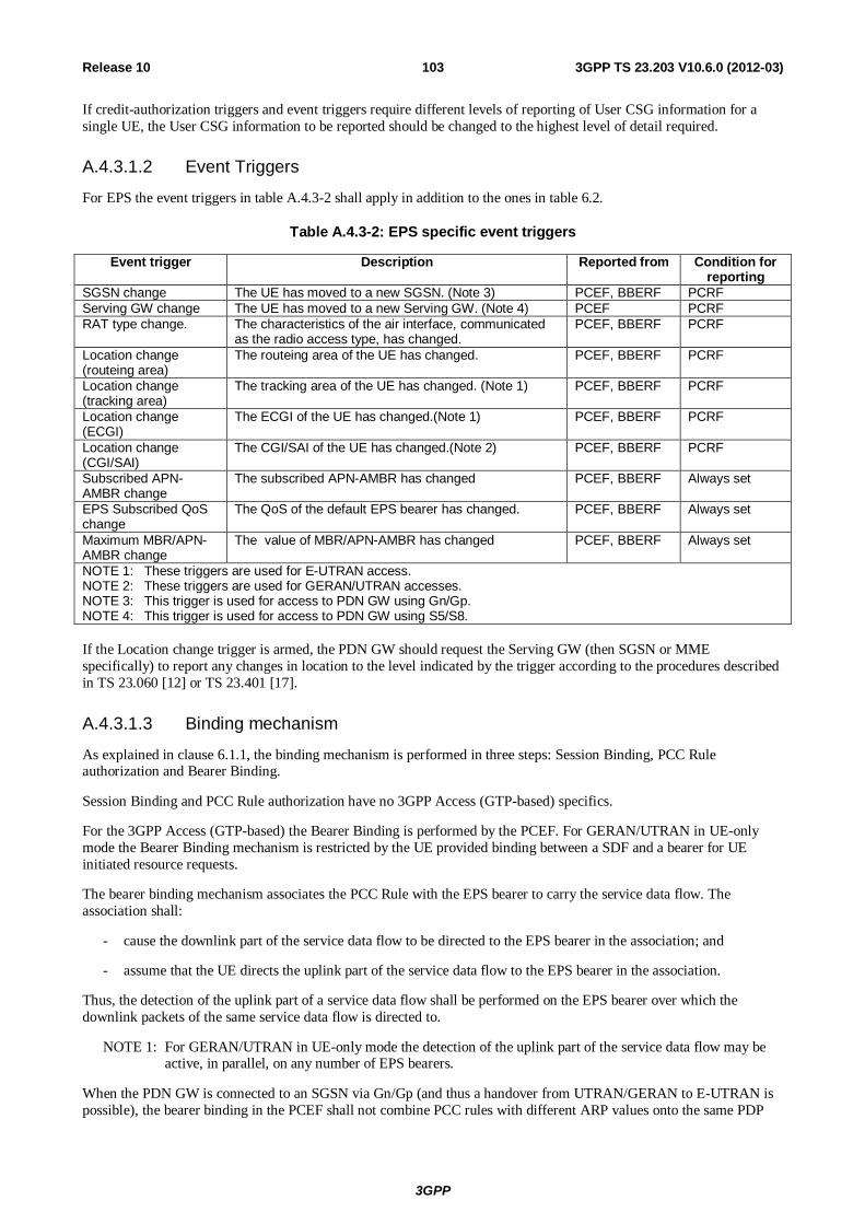
3GPP
3GPP TS 23.203 V10.6.0 (2012-03) 103Release 10
If credit-authorization triggers and event triggers require different levels of reporting of User CSG information for a single UE, the User CSG information to be reported should be changed to the highest level of detail required.
A.4.3.1.2 Event Triggers
For EPS the event triggers in table A.4.3-2 shall apply in addition to the ones in table 6.2.
Table A.4.3-2: EPS specific event triggers
Event trigger Description Reported from Condition for reporting
SGSN change The UE has moved to a new SGSN. (Note 3) PCEF, BBERF PCRF Serving GW change The UE has moved to a new Serving GW. (Note 4) PCEF PCRF RAT type change. The characteristics of the air interface, communicated
as the radio access type, has changed. PCEF, BBERF PCRF
Location change (routeing area)
The routeing area of the UE has changed. PCEF, BBERF PCRF
Location change (tracking area)
The tracking area of the UE has changed. (Note 1) PCEF, BBERF PCRF
Location change (ECGI)
The ECGI of the UE has changed.(Note 1) PCEF, BBERF PCRF
Location change (CGI/SAI)
The CGI/SAI of the UE has changed.(Note 2) PCEF, BBERF PCRF
Subscribed APN-AMBR change
The subscribed APN-AMBR has changed PCEF, BBERF Always set
EPS Subscribed QoS change
The QoS of the default EPS bearer has changed. PCEF, BBERF Always set
Maximum MBR/APN-AMBR change
The value of MBR/APN-AMBR has changed PCEF, BBERF Always set
NOTE 1: These triggers are used for E-UTRAN access. NOTE 2: These triggers are used for GERAN/UTRAN accesses. NOTE 3: This trigger is used for access to PDN GW using Gn/Gp. NOTE 4: This trigger is used for access to PDN GW using S5/S8. If the Location change trigger is armed, the PDN GW should request the Serving GW (then SGSN or MME specifically) to report any changes in location to the level indicated by the trigger according to the procedures described in TS 23.060 [12] or TS 23.401 [17].
A.4.3.1.3 Binding mechanism
As explained in clause 6.1.1, the binding mechanism is performed in three steps: Session Binding, PCC Rule authorization and Bearer Binding.
Session Binding and PCC Rule authorization have no 3GPP Access (GTP-based) specifics.
For the 3GPP Access (GTP-based) the Bearer Binding is performed by the PCEF. For GERAN/UTRAN in UE-only mode the Bearer Binding mechanism is restricted by the UE provided binding between a SDF and a bearer for UE initiated resource requests.
The bearer binding mechanism associates the PCC Rule with the EPS bearer to carry the service data flow. The association shall:
- cause the downlink part of the service data flow to be directed to the EPS bearer in the association; and
- assume that the UE directs the uplink part of the service data flow to the EPS bearer in the association.
Thus, the detection of the uplink part of a service data flow shall be performed on the EPS bearer over which the downlink packets of the same service data flow is directed to.
NOTE 1: For GERAN/UTRAN in UE-only mode the detection of the uplink part of the service data flow may be active, in parallel, on any number of EPS bearers.
When the PDN GW is connected to an SGSN via Gn/Gp (and thus a handover from UTRAN/GERAN to E-UTRAN is possible), the bearer binding in the PCEF shall not combine PCC rules with different ARP values onto the same PDP
3GPP
3GPP TS 23.203 V10.6.0 (2012-03) 104Release 10
context. For the UE-only mode (which is based on a UE provided binding) PCC rules with different ARP values shall not be authorized for the same PDP context.
NOTE 2: If Evolved ARP is not supported by the SGSN then this enables a modification of the EPS bearer ARP without impacting the service assignment after a handover to E-UTRAN or after relocation to a S4-SGSN or a Gn/Gp SGSN that supports Evolved ARP.
A.4.3.1.4 Policy Control
For 3GPP Access (GTP based) the policy control functionalities should include the following functionality for QoS control (in addition to the functionalities listed in clause 6.1.5):
- Authorization and enforcement of the maximum QoS that is authorized for the total bandwidth usage of non-GBR QCIs at an APN.
- Authorization and enforcement of the maximum QoS allocated to the Default EPS bearer. The Default EPS bearer shall have a non-GBR QCI as defined in TS 23.401 [17], clause 4.7.2.1.
A.4.3.2 Functional Entities
A.4.3.2.1 Policy Control and Charging Rules Function (PCRF)
The following information represents 3GPP EPS specific values of the ones listed in clause 6.2.1.1:
- Type of IP-CAN is set to 3GPP-EPS.
The PCEF may provide the following information (in addition to the information in clause 6.2.1.1):
- Subscribed APN-AMBR;
- Default EPS Bearer QoS;
- Maximum MBR/APN-AMBR.
The SPR may provide the following information for a subscriber (in addition to the information in clause 6.2.1.1) connecting to a specific PDN:
- Authorized APN-AMBR for 3GPP Access;
- Authorized Default EPS Bearer QoS.
The Authorized APN-AMBR and the Authorized Default EPS Bearer QoS are derived by the PCRF from SPR interaction, according to operator policy.
The PCRF shall upon indication of PCC rule removal due to PS to CS handover notify the AF that the associated flows are no longer served by the PS-domain due to PS to CS handover.
The PCRF shall provide SDF filters in the PCC rule as received in the packet filter information from the PCEF.
If the PCRF receives a request for addition of service data flow(s) with a reference to existing SDF filter identities (and by that to existing PCC rule(s)), the PCRF shall use the QCI or ARP of the existing PCC rule for the new service data flow(s).
NOTE: The reference to existing SDF filter identities informs the PCRF that the request is confined to an existing bearer, having bearer bindings with PCC rules that have the same QCI/ARP combination. Assigning a different QCI or ARP to the new SDFs would cause the procedure to fail, since the PCEF cannot map the new SDFs to another bearer.
A.4.3.2.2 Policy and Charging Enforcement Function (PCEF)
In the 3GPP Access (GTP-based) architecture the PCEF enforce QoS Policies as indicated by the PCRF in accordance to what is stated in clause 6.2.2.1 with the following additions:
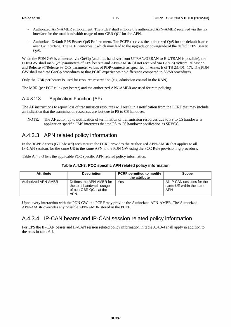
3GPP
3GPP TS 23.203 V10.6.0 (2012-03) 105Release 10
- Authorized APN-AMBR enforcement. The PCEF shall enforce the authorized APN-AMBR received via the Gx interface for the total bandwidth usage of non-GBR QCI for the APN.
- Authorized Default EPS Bearer QoS Enforcement. The PCEF receives the authorized QoS for the default bearer over Gx interface. The PCEF enforces it which may lead to the upgrade or downgrade of the default EPS Bearer QoS.
When the PDN GW is connected via Gn/Gp (and thus handover from UTRAN/GERAN to E-UTRAN is possible), the PDN-GW shall map QoS parameters of EPS bearers and APN-AMBR (if not received via Gn/Gp) to/from Release 99 and Release 97/Release 98 QoS parameter values of PDP-contexts as specified in Annex E of TS 23.401 [17]. The PDN GW shall mediate Gn/Gp procedures so that PCRF experiences no difference compared to S5/S8 procedures.
Only the GBR per bearer is used for resource reservation (e.g. admission control in the RAN).
The MBR (per PCC rule / per bearer) and the authorized APN-AMBR are used for rate policing.
A.4.3.2.3 Application Function (AF)
The AF instructions to report loss of transmission resources will result in a notification from the PCRF that may include an indication that the transmission resources are lost due to PS to CS handover.
NOTE: The AF action up to notification of termination of transmission resources due to PS to CS handover is application specific. IMS interprets that the PS to CS handover notification as SRVCC.
A.4.3.3 APN related policy information In the 3GPP Access (GTP-based) architecture the PCRF provides the Authorized APN-AMBR that applies to all IP-CAN sessions for the same UE to the same APN to the PDN GW using the PCC Rule provisioning procedure.
Table A.4.3-3 lists the applicable PCC specific APN related policy information.
Table A.4.3-3: PCC specific APN related policy information
Attribute Description PCRF permitted to modify the attribute
Scope
Authorized APN-AMBR Defines the APN-AMBR for the total bandwidth usage of non-GBR QCIs at the APN.
Yes All IP-CAN sessions for the same UE within the same APN
Upon every interaction with the PDN GW, the PCRF may provide the Authorized APN-AMBR. The Authorized APN-AMBR overrides any possible APN-AMBR stored in the PCEF.
A.4.3.4 IP-CAN bearer and IP-CAN session related policy information For EPS the IP-CAN bearer and IP-CAN session related policy information in table A.4.3-4 shall apply in addition to the ones in table 6.4.
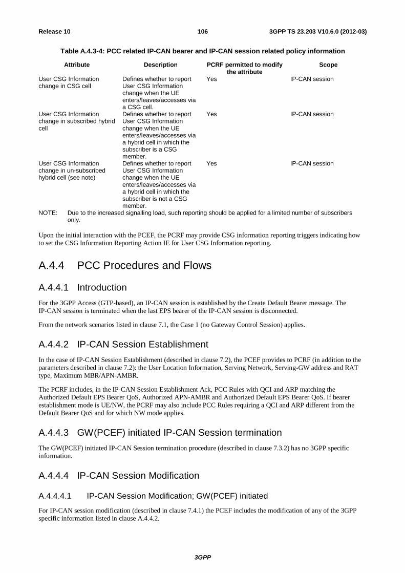
3GPP
3GPP TS 23.203 V10.6.0 (2012-03) 106Release 10
Table A.4.3-4: PCC related IP-CAN bearer and IP-CAN session related policy information
Attribute Description PCRF permitted to modify the attribute
Scope
User CSG Information change in CSG cell
Defines whether to report User CSG Information change when the UE enters/leaves/accesses via a CSG cell.
Yes IP-CAN session
User CSG Information change in subscribed hybrid cell
Defines whether to report User CSG Information change when the UE enters/leaves/accesses via a hybrid cell in which the subscriber is a CSG member.
Yes IP-CAN session
User CSG Information change in un-subscribed hybrid cell (see note)
Defines whether to report User CSG Information change when the UE enters/leaves/accesses via a hybrid cell in which the subscriber is not a CSG member.
Yes IP-CAN session
NOTE: Due to the increased signalling load, such reporting should be applied for a limited number of subscribers only.
Upon the initial interaction with the PCEF, the PCRF may provide CSG information reporting triggers indicating how to set the CSG Information Reporting Action IE for User CSG Information reporting.
A.4.4 PCC Procedures and Flows
A.4.4.1 Introduction For the 3GPP Access (GTP-based), an IP-CAN session is established by the Create Default Bearer message. The IP-CAN session is terminated when the last EPS bearer of the IP-CAN session is disconnected.
From the network scenarios listed in clause 7.1, the Case 1 (no Gateway Control Session) applies.
A.4.4.2 IP-CAN Session Establishment In the case of IP-CAN Session Establishment (described in clause 7.2), the PCEF provides to PCRF (in addition to the parameters described in clause 7.2): the User Location Information, Serving Network, Serving-GW address and RAT type, Maximum MBR/APN-AMBR.
The PCRF includes, in the IP-CAN Session Establishment Ack, PCC Rules with QCI and ARP matching the Authorized Default EPS Bearer QoS, Authorized APN-AMBR and Authorized Default EPS Bearer QoS. If bearer establishment mode is UE/NW, the PCRF may also include PCC Rules requiring a QCI and ARP different from the Default Bearer QoS and for which NW mode applies.
A.4.4.3 GW(PCEF) initiated IP-CAN Session termination The GW(PCEF) initiated IP-CAN Session termination procedure (described in clause 7.3.2) has no 3GPP specific information.
A.4.4.4 IP-CAN Session Modification
A.4.4.4.1 IP-CAN Session Modification; GW(PCEF) initiated
For IP-CAN session modification (described in clause 7.4.1) the PCEF includes the modification of any of the 3GPP specific information listed in clause A.4.4.2.
3GPP
3GPP TS 23.203 V10.6.0 (2012-03) 107Release 10
If the PS to CS handover indicator is set for an IP-CAN bearer that is deleted, the PCEF reports termination of transmission resources for associated PCC Rules due to PS to CS handover.
The PCRF may provide the following parameters in the Acknowledgement of the IP-CAN Session Modification to the PDN GW (in addition to the parameters in clause 7.4.1): Authorized APN-AMBR, Authorized Default EPS Bearer QoS.
Based on operator policy and Maximum MBR/APN-AMBR, the PCRF may re-authorize MBR/APN-AMBR.
A.4.4.4.2 IP-CAN Session Modification; PCRF initiated
The PCRF may provide the following parameters in the Policy and Charging Rule Provision to the PDN GW (in addition to the parameters in clause 7.4.2): Authorized APN-AMBR, Authorized Default EPS Bearer QoS.
A.5 3GPP Accesses (GERAN/UTRAN/E-UTRAN) - PMIP-based EPC
A.5.0 General For 3GPP Access (PMIP-based), architecture details are described in TS 23.402 [18].
When PMIP-based S5/S8 has been deployed, the IP-CAN-specific parameter exchange occurs by means of IP-CAN Session Modification messages including the necessary information.
A.5.1 High Level Requirements
A.5.1.0 General The same requirements as in clause A.4.1 apply for 3GPP Access (PMIP-based).
A.5.1.1 QoS control For 3GPP Access (PMIP based) the same requirements as defined in clause A.4.1.2 apply.
A.5.2 Architectural Model and Reference Points
A.5.2.1 Reference architecture In the 3GPP Access (PMIP-based) architecture, see TS 23.402 [18],
- the Policy and Charging Enforcement Function is allocated to the PDN GW;
- the Bearer Binding and Event Reporting Function (BBERF) is allocated to the Serving GW.
The Gxx applies and corresponds to the Gxc, as defined in TS 23.402 [18]. One Gateway Control Session corresponds to one IP-CAN session.
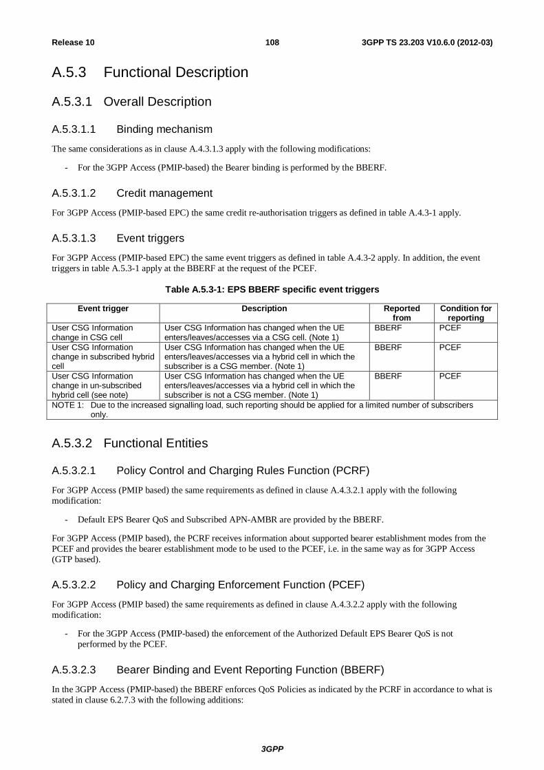
3GPP
3GPP TS 23.203 V10.6.0 (2012-03) 108Release 10
A.5.3 Functional Description
A.5.3.1 Overall Description
A.5.3.1.1 Binding mechanism
The same considerations as in clause A.4.3.1.3 apply with the following modifications:
- For the 3GPP Access (PMIP-based) the Bearer binding is performed by the BBERF.
A.5.3.1.2 Credit management
For 3GPP Access (PMIP-based EPC) the same credit re-authorisation triggers as defined in table A.4.3-1 apply.
A.5.3.1.3 Event triggers
For 3GPP Access (PMIP-based EPC) the same event triggers as defined in table A.4.3-2 apply. In addition, the event triggers in table A.5.3-1 apply at the BBERF at the request of the PCEF.
Table A.5.3-1: EPS BBERF specific event triggers
Event trigger Description Reported from
Condition for reporting
User CSG Information change in CSG cell
User CSG Information has changed when the UE enters/leaves/accesses via a CSG cell. (Note 1)
BBERF PCEF
User CSG Information change in subscribed hybrid cell
User CSG Information has changed when the UE enters/leaves/accesses via a hybrid cell in which the subscriber is a CSG member. (Note 1)
BBERF PCEF
User CSG Information change in un-subscribed hybrid cell (see note)
User CSG Information has changed when the UE enters/leaves/accesses via a hybrid cell in which the subscriber is not a CSG member. (Note 1)
BBERF PCEF
NOTE 1: Due to the increased signalling load, such reporting should be applied for a limited number of subscribers only.
A.5.3.2 Functional Entities
A.5.3.2.1 Policy Control and Charging Rules Function (PCRF)
For 3GPP Access (PMIP based) the same requirements as defined in clause A.4.3.2.1 apply with the following modification:
- Default EPS Bearer QoS and Subscribed APN-AMBR are provided by the BBERF.
For 3GPP Access (PMIP based), the PCRF receives information about supported bearer establishment modes from the PCEF and provides the bearer establishment mode to be used to the PCEF, i.e. in the same way as for 3GPP Access (GTP based).
A.5.3.2.2 Policy and Charging Enforcement Function (PCEF)
For 3GPP Access (PMIP based) the same requirements as defined in clause A.4.3.2.2 apply with the following modification:
- For the 3GPP Access (PMIP-based) the enforcement of the Authorized Default EPS Bearer QoS is not performed by the PCEF.
A.5.3.2.3 Bearer Binding and Event Reporting Function (BBERF)
In the 3GPP Access (PMIP-based) the BBERF enforces QoS Policies as indicated by the PCRF in accordance to what is stated in clause 6.2.7.3 with the following additions:
3GPP
3GPP TS 23.203 V10.6.0 (2012-03) 109Release 10
- Authorized Default EPS Bearer QoS Enforcement. The BBERF receives the authorized QoS for the default bearer over Gxx interface. The BBERF enforces it which may lead to the upgrade or downgrade of the default EPS Bearer QoS.
A.5.3.3 Void
A.5.3.4 APN related policy information For 3GPP Access (PMIP based) the same requirements as defined in clause A.4.3.3 apply.
A.5.3.5 IP-CAN bearer and IP-CAN session related policy information For 3GPP Access (PMIP based) the same requirements as defined in clause A.4.3.4 apply.
A.5.4 PCC Procedures and Flows
A.5.4.1 Introduction For the 3GPP Access (PMIP-based), the IP-CAN session is established by the Proxy Binding Update message to the PDN-GW. The IP-CAN session is terminated when the PMIP session is terminated.
From the network scenarios listed in clause 7.1, the Case 2b applies.
A.5.4.2 Gateway Control Session Establishment For the Gateway Control Session Establishment Procedure (see clause 7.7.1), the Serving GW includes the following additional information in the Gateway Control Session Establishment message (in addition to the parameters described in clause 7.7.1): User Location Information, user GSG information, (if received from the MME), Serving-GW address, Serving Network, RAT Type, Default EPS Bearer QoS and if available the APN-AMBR are provided to the PCRF.
The PCRF includes, in the Acknowledge Gateway Control Session Establishment (in addition to the parameters described in clause 7.7.1): QoS Rules with QCI and ARP matching the Default EPS Bearer QoS. If the bearer establishment mode is UE/NW, the PCRF may also include QoS Rules requiring a QCI and ARP different from the Default EPS Bearer QoS and for which NW mode applies.
In support of PDP Context Activation procedures over S4, the BBERF must indicate various session parameters, e.g. the RAT type, to the PCRF.
The PCRF may provide the following parameters in the Acknowledgement of the Gateway Control Session Establishment to the Serving GW (in addition to the parameters described in clause 7.7.1): Authorized APN-AMBR, Authorized Default EPS Bearer QoS.
A.5.4.3 Gateway Control and QoS Rules Request In the case of Gateway Control and QoS Rules Request (described in clause 7.7.3) the BBERF includes the addition/modification/removal of any the 3GPP specific information listed in clause A.5.4.2.
When a change of RAT without S-GW relocation occurs, the BBERF signals the RAT type change as a parameter in an event report sent from the BBERF to the PCRF. An event report is the then sent, indicating the RAT type change, from the PCRF to the PCEF.
When Secondary PDP Context Activation occurs, the S4 SGSN performs a Request Bearer Resource Allocation procedure with the Serving GW. The Serving GW supplies the parameters required by the PCEF to properly handle the allocation of resources. These parameters are sent from the BBERF (Serving GW) to the PCRF for further processing when a PMIP-based S5/S8 is deployed.
3GPP
3GPP TS 23.203 V10.6.0 (2012-03) 110Release 10
The PCRF may provide the following parameters in the Acknowledgement of the Gateway Control and QoS Rules Request to the Serving GW (in addition to the parameters described in clause 7.7.3): Authorized APN-AMBR, Authorized Default EPS Bearer QoS.
For the purpose of event reporting to the PCEF the BBERF may generate Event Reports to the PCRF if this has been requested by the PCRF.
If the PS to CS handover indicator is set for an IP-CAN bearer that is deleted, the BBERF reports termination of transmission resources for associated QoS Rules due to PS to CS handover.
A.5.4.4 Gateway Control and QoS Rules Provisioning In the case of Gateway Control and QoS Rules Provisioning (described in clause 7.7.4) the PCRF may provide the following parameters (in addition to the parameters described in clause 7.7.4) to the Serving GW: Authorized APN-AMBR, Authorized Default EPS Bearer QoS.
For the purpose of event reporting to the PCEF the PCRF may request Event Reports from the BBERF. In response to such request the BBERF shall provide the present value(s) of the event parameters.
A.5.4.5 IP-CAN Session Establishment The PCRF may provide the following parameters in the Acknowledgement of the IP-CAN Session Establishment to the PDN GW (in addition to the parameters in clause 7.2): Authorized APN-AMBR, User Location Information, user GSG information (if received from the BBERF).
A.5.4.6 IP-CAN Session Modification
A.5.4.6.1 IP-CAN Session Modification; GW(PCEF) initiated
The PCRF may provide the following parameters in the Acknowledgement of the IP-CAN Session Modification to the PDN GW (in addition to the parameters in clause 7.4.1): Authorized APN-AMBR.
A.5.4.6.2 IP-CAN Session Modification; PCRF initiated
The PCRF may provide the following parameters in the Policy and Charging Rule Provision to the PDN GW (in addition to the parameters in clause 7.4.2): Authorized APN-AMBR, User Location Information (if received from the BBERF), user GSG information (if received from the BBERF).
A.5.4.6.3 Void

3GPP
3GPP TS 23.203 V10.6.0 (2012-03) 111Release 10
Annex B (informative): Void

3GPP
3GPP TS 23.203 V10.6.0 (2012-03) 112Release 10
Annex C (informative): Void
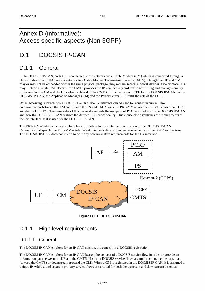
3GPP
3GPP TS 23.203 V10.6.0 (2012-03) 113Release 10
Annex D (informative): Access specific aspects (Non-3GPP)
D.1 DOCSIS IP-CAN
D.1.1 General In the DOCSIS IP-CAN, each UE is connected to the network via a Cable Modem (CM) which is connected through a Hybrid Fibre Coax (HFC) access network to a Cable Modem Termination System (CMTS). Though the UE and CM may or may not be embedded within the same physical package, they remain separate logical devices. One or more UEs may subtend a single CM. Because the CMTS provides the IP connectivity and traffic scheduling and manages quality of service for the CM and the UEs which subtend it, the CMTS fulfils the role of PCEF for the DOCSIS IP-CAN. In the DOCSIS IP-CAN, the Application Manager (AM) and the Policy Server (PS) fulfil the role of the PCRF.
When accessing resources via a DOCSIS IP-CAN, the Rx interface can be used to request resources. The communication between the AM and PS and the PS and CMTS uses the PKT-MM-2 interface which is based on COPS and defined in J.179. The remainder of this clause documents the mapping of PCC terminology to the DOCSIS IP-CAN and how the DOCSIS IP-CAN realizes the defined PCC functionality. This clause also establishes the requirements of the Rx interface as it is used for the DOCSIS IP-CAN.
The PKT-MM-2 interface is shown here for information to illustrate the organization of the DOCSIS IP-CAN. References that specify the PKT-MM-2 interface do not constitute normative requirements for the 3GPP architecture. The DOCSIS IP-CAN does not intend to pose any new normative requirements for the Gx interface.
DOCSIS IP-CAN CMTS
PCEF
PS
Pkt-mm-2 (COPS)
CM UE
AM
PCRF
AF Rx
Figure D.1.1: DOCSIS IP-CAN
D.1.1 High level requirements
D.1.1.1 General The DOCSIS IP-CAN employs for an IP-CAN session, the concept of a DOCSIS registration.
The DOCSIS IP-CAN employs for an IP-CAN bearer, the concept of a DOCSIS service flow in order to provide an information path between the UE and the CMTS. Note that DOCSIS service flows are unidirectional, either upstream (toward the CMTS) or downstream (toward the CM). When a CM is registered in the DOCSIS IP-CAN, it is assigned a unique IP Address and separate primary service flows are created for both the upstream and downstream direction
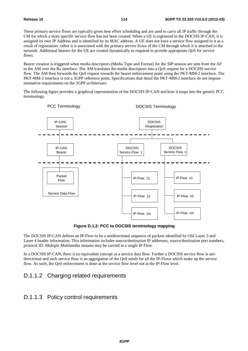
3GPP
3GPP TS 23.203 V10.6.0 (2012-03) 114Release 10
These primary service flows are typically given best effort scheduling and are used to carry all IP traffic through the CM for which a more specific service flow has not been created. When a UE is registered in the DOCSIS IP-CAN, it is assigned its own IP Address and is identified by its MAC address. A UE does not have a service flow assigned to it as a result of registration; rather it is associated with the primary service flows of the CM through which it is attached to the network. Additional bearers for the UE are created dynamically as required to provide appropriate QoS for service flows.
Bearer creation is triggered when media descriptors (Media Type and Format) for the SIP session are sent from the AF to the AM over the Rx interface. The AM translates the media descriptors into a QoS request for a DOCSIS service flow. The AM then forwards the QoS request towards the bearer enforcement point using the PKT-MM-2 interface. The PKT-MM-2 interface is not a 3GPP reference point, Specifications that detail the PKT-MM-2 interface do not impose normative requirements on the 3GPP architecture.
The following figure provides a graphical representation of the DOCSIS IP-CAN and how it maps into the generic PCC terminology.
IP-CAN Session
DOCSIS Registration
IP-CAN Bearer
DOCSIS Service Flow 1
DOCSIS Service Flow n
Packet Flow IP-Flow 11
Service Data Flow
PCC Terminology DOCSIS Terminology
IP-Flow 12
IP-Flow 1m
IP-Flow n1
IP-Flow n2
IP-Flow nm
Figure D.1.2: PCC to DOCSIS terminology mapping
The DOCSIS IP-CAN defines an IP-Flow to be a unidirectional sequence of packets identified by OSI Layer 3 and Layer 4 header information. This information includes source/destination IP addresses, source/destination port numbers, protocol ID. Multiple Multimedia streams may be carried in a single IP Flow.
In a DOCSIS IP-CAN, there is no equivalent concept as a service data flow. Further a DOCSIS service flow is uni-directional and each service flow is an aggregation of the QoS needs for all the IP-Flows which make up the service flow. As such, the QoS enforcement is done at the service flow level not at the IP-Flow level.
D.1.1.2 Charging related requirements
D.1.1.3 Policy control requirements
3GPP
3GPP TS 23.203 V10.6.0 (2012-03) 115Release 10
D.1.2 Architecture model and reference points
D.1.2.1 Reference points
D.1.2.1.1 Rx reference point
D.1.2.1.2 Gx reference point
D.1.2.1.3 Void
D.1.3 Functional description
D.1.3.1 Overall description The DOSCIS IP-CAN employs for an IP-CAN bearer, the concept of a DOCSIS service flow in order to provide an information path between the UE and the CMTS. When a Cable Modem is registered in the DOCSIS IP-CAN, primary upstream and downstream service flows are created.
When a UE is registered in the DOCSIS IP-CAN it is associated with the primary service flows of the cable modem through which it is attached to the network. Based on session information provided by the AF using the Rx reference point, the Application Manager will determine QoS requirements for each IP flow. IP flows which do not require special quality of service treatment may be carried over the primary service flows. For other IP flows which require specific QoS treatment, the Policy Server requests the CMTS to admit the flows using the pkt-mm-2 interface providing detailed information of the QoS requirements. Provided that resources are available, the CMTS will create additional bearers dynamically and push the appropriate traffic filters to the cable modem.
D.1.3.1.1 Binding mechanism
In the DOCSIS IP-CAN, the binding mechanism is achieved through the use of traffic Classifiers. These Classifiers filter traffic destined to a UE behind a Cable Modem or sourced from a UE behind a Cable Modem, to a particular DOCSIS service flow. DOCSIS Classifiers contain the following attributes which can be used to filter IP traffic:
- IP Type of Service – Range and Mask;
- IP Protocol;
- IP Source Address;
- IP Source Mask;
- IP Destination Address;
- IP Destination Mask;
- TCP/UDP Source Port Start;
- TCP/UDP Source Port End;
- TCP/UDP Destination Port Start;
- TCP/UDP Destination Port End.
The Classifier(s) which are used for a particular DOCSIS service flow are communicated to the CMTS by the Policy Server (on behalf of the Application Manager) via the pkt-mm-2 interface. The Application Manager will specify the
3GPP
3GPP TS 23.203 V10.6.0 (2012-03) 116Release 10
QoS requirements for the IP flow, the direction of the IP flow, and the Classifier(s) which are to be used for the DOCSIS service flow serving the IP flow.
When a session is no longer in use, the Application Manager communicates to the CMTS to tear down the resources associated with the session. Based on this communication, the CMTS will remove the DOCSIS service flow(s) and any Classifier(s) associated with the service flow(s), and inform the Cable Modem of the removal. Traffic which previously matched the removed Classifier(s) will now be placed on either the upstream or downstream primary DOCSIS service flow, depending on the direction of the traffic.
D.1.3.2 Functional entities
D.1.3.2.1 Policy Control and Charging Rules Function (PCRF)
In the DOCSIS IP-CAN, the Application Manager (AM) and the Policy Server (PS) fulfil the role of the PCRF.
The AM receives media descriptors (Media Type and Format) from the AF for SIP sessions and maps the QoS needs of the session to a FlowSpec, The FlowSpec is a layer 2 independent representation of the bandwidth and QoS requirements for the flow derived from the media descriptors using a well defined algorithm. The AM and PS provide network resource control in the DOCSIS IP-CAN by managing the CMTS using the PacketCable Multimedia interface pkt-mm-2.
The AM and PS map IP flows to DOCSIS service flows in accordance with the operator's policies and based on the media format information provided by the AF.
D.1.3.2.1.1 Input for PCC decisions
The AM accepts any of the following input as a basis for decisions on PCC rule operations:
- Per IP-CAN session (e.g.: UE IP address);
- Requested QoS, media format, priority indicator.
The SPR may provide the following information:
- Subscribers maximum allowed QoS resources.
Subscriber's maximum allowed bit rate for upstream and downstream.
D.1.3.2.2 Policy and Charging Enforcement Function (PCEF)
The CMTS provides PCEF equivalent functionality within the DOCSIS IP-CAN. The CMTS creates, modifies, and deletes DOCSIS service flows upon request of the Policy Server. The CMTS receives requests from the Policy Server over the pkt-mm-2 interface.
D.1.3.2.3 Application Function (AF)
D.1.3.3 Policy and charging control rule
D.1.3.3.1 General
D.1.3.3.2 Policy and charging control rule operations
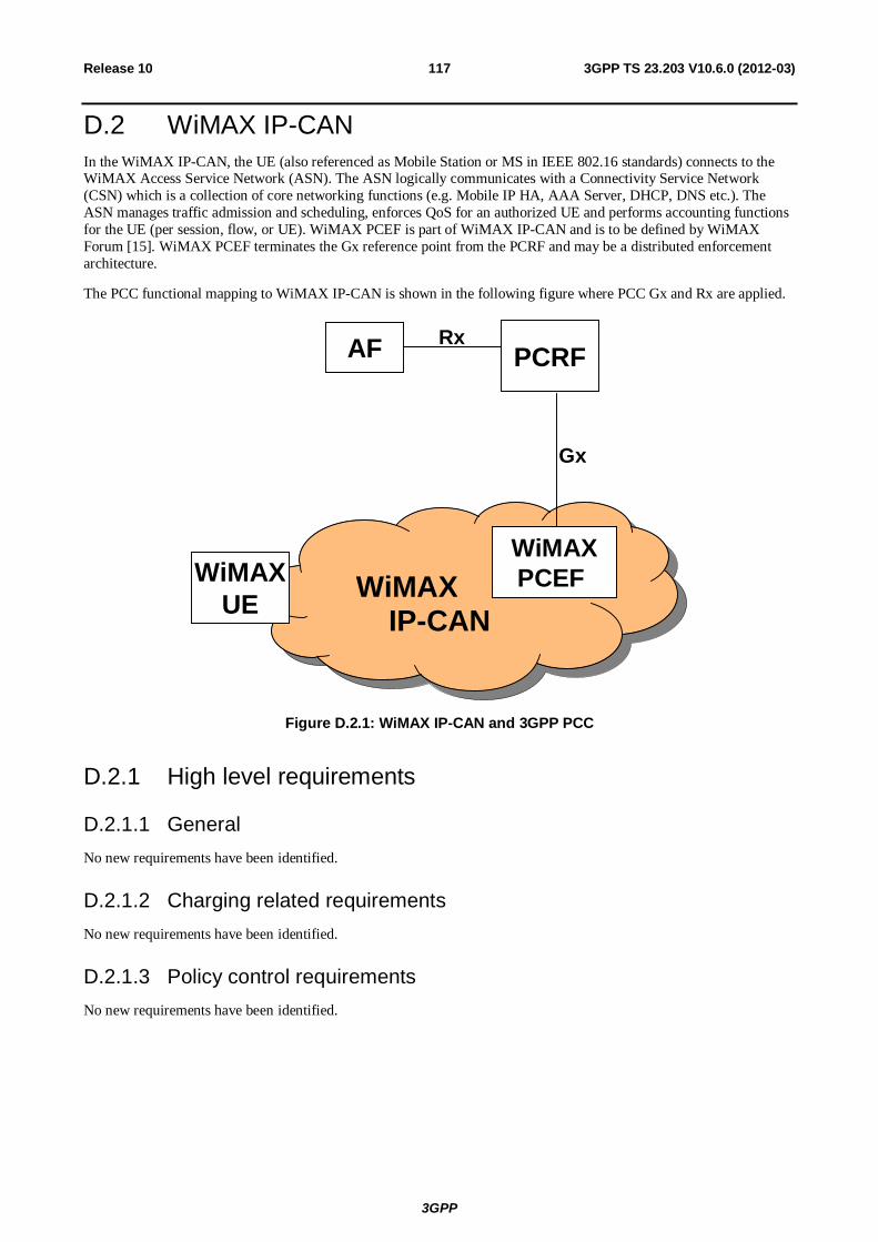
3GPP
3GPP TS 23.203 V10.6.0 (2012-03) 117Release 10
D.2 WiMAX IP-CAN In the WiMAX IP-CAN, the UE (also referenced as Mobile Station or MS in IEEE 802.16 standards) connects to the WiMAX Access Service Network (ASN). The ASN logically communicates with a Connectivity Service Network (CSN) which is a collection of core networking functions (e.g. Mobile IP HA, AAA Server, DHCP, DNS etc.). The ASN manages traffic admission and scheduling, enforces QoS for an authorized UE and performs accounting functions for the UE (per session, flow, or UE). WiMAX PCEF is part of WiMAX IP-CAN and is to be defined by WiMAX Forum [15]. WiMAX PCEF terminates the Gx reference point from the PCRF and may be a distributed enforcement architecture.
The PCC functional mapping to WiMAX IP-CAN is shown in the following figure where PCC Gx and Rx are applied.
WiMAX IP -CAN
WiMAX IP-CAN
WiMAX
UE
PCRF
Gx
AF Rx
WiMAX
PCEF
Figure D.2.1: WiMAX IP-CAN and 3GPP PCC
D.2.1 High level requirements
D.2.1.1 General No new requirements have been identified.
D.2.1.2 Charging related requirements No new requirements have been identified.
D.2.1.3 Policy control requirements No new requirements have been identified.
3GPP
3GPP TS 23.203 V10.6.0 (2012-03) 118Release 10
D.2.2 Architecture model and reference points
D.2.2.1 Reference points
D.2.2.1.1 Rx reference point
WiMAX IP-CAN imposes no new requirements to the Rx reference point.
D.2.2.1.2 Gx reference point
WiMAX IP-CAN imposes no new requirements to the Gx reference point other than WiMAX specific values for existing Gx parameters (e.g. RAT type) as described in [15].
D.2.2.1.3 Sp reference point
WiMAX IP-CAN imposes no new requirements to the Sp reference point.
D.2.3 Functional description
D.2.3.1 Overall description The WiMAX IP-CAN employs for an IP-CAN bearer, the concept of a WiMAX service flow, in order to provide a data path between the UE and the WiMAX CSN via the ASN. When a UE is registered in the WiMAX IP-CAN, it is associated with one or more WiMAX service flows. Based on session information provided by the AF via the Rx reference point, the PCRF determines the QoS requirements for each service by constructing PCC rules. The PCRF requests the WiMAX IP-CAN via Gx interface to enforce the authorized PCC rules on the WiMAX service flows. The PCEF function in the WiMAX IP-CAN enforces the PCC rules received from the PCRF. Provided that resources are available, the ASN creates and configures logical bearers and enforces creation of appropriate traffic classes associated with service flows compliant with IEEE 802.16 standards for the air interface and IP-CAN bearer capabilities in the ASN (e.g. DiffServ).
D.2.3.1.1 Binding mechanism
D.2.3.1.2 Credit management
D.2.3.1.3 Event triggers
D.2.3.2 Functional entities
D.2.3.2.1 Policy Control and Charging Rules Function (PCRF)
The 3GPP PCRF is used for the WiMAX IP-CAN. The PCRF interacts with WiMAX IP-CAN using 3GPP Gx reference point.
3GPP
3GPP TS 23.203 V10.6.0 (2012-03) 119Release 10
D.2.3.2.2 Policy and Charging Enforcement Function (PCEF)
For WiMAX IP-CAN, PCEF functions may be distributed. It additionally:
- Terminates the Gx reference point from PCRF and may act as a proxy for the PCRF.
- Handles the enforcement function relocation in WiMAX IP-CAN in a way that is transparent to the PCRF.
D.2.3.2.3 Application Function (AF)
WiMAX IP-CAN imposes no requirements to the AF functionalities.
D.2.3.3 Policy and charging control rule
D.2.3.3.1 General
D.2.3.3.1 Policy and charging control rule operations

3GPP
3GPP TS 23.203 V10.6.0 (2012-03) 120Release 10
Annex E (informative): Void

3GPP
3GPP TS 23.203 V10.6.0 (2012-03) 121Release 10
Annex F (informative): Void
3GPP
3GPP TS 23.203 V10.6.0 (2012-03) 122Release 10
Annex G (informative): PCC rule precedence configuration The precedence information is part of the PCC rule (see clause 6.3.1) and instructs the PCEF in which order the service data flow templates of the active PCC rules needs to be analyzed when an IP packet arrives. This mechanism ensures that the service data flows can be correctly identified even if the service data flow templates contain overlapping service data flow filters.
Within the PCC framework it is possible to use different types of PCC rules for which the service data flow templates may not always be known by the PCRF. Therefore, the PCC rule precedence information needs to be carefully configured to avoid certain situations e.g. a dynamic PCC rule cannot be applied for service data flow detection due to a pre-defined PCC rule not known to the PCRF with overlapping filter information and a higher precedence.
For example, an operator could structure the value range of the precedence information into separate value ranges (in decreasing order) for the different types of PCC rules as follows:
- dynamic PCC rules;
- pre-defined PCC rules known to the PCRF;
- pre-defined PCC rules not known to the PCRF;
- dynamic PCC rules for non-operator controlled services, i.e. those which are generated by the PCRF based on the UE provided traffic mapping information (and which take over the UE provided precedence information).
3GPP
3GPP TS 23.203 V10.6.0 (2012-03) 123Release 10
Annex H (normative): Access specific aspects (EPC-based Non-3GPP)
H.1 General An EPC-based non-3GPP IP-CAN (TS 23.402 [18]), which requires the Gxa for dynamic QoS control, shall include the BBERF. The allocation of a BBERF to a node within the non-3GPP IP-CAN is out of 3GPP scope, unless otherwise specified in this Annex.
H.2 EPC-based cdma2000 HRPD Access In case of EPC-based cdma2000 HRPD access the BBERF is located in the HRPD Serving Gateway (HSGW) defined in 3GPP2 X.P0057 [20].
The HSGW of an EPC-based cdma2000 HRPD access that supports a Gxa interface shall support all the Gxa procedures defined in this specification.
NOTE 1: If the HSGW does not support the Gxa interface, the HSGW performs QoS enforcement in the HRPD access based on subscription-based QoS policies provided by the 3GPP AAA Server/Proxy during access authentication and/or static QoS policies configured in the HSGW. However, this is out of the scope of this specification.
During the pre-registration phase in case of optimised EUTRAN-to-HRPD handovers, the Serving GW and the HSGW are associated with the IP-CAN session(s) of the UE in the PCRF. The HSGW is the non-primary BBERF.
NOTE 2: The HSGW performs QoS mapping between the QoS parameters exchanged across Gxa interface and the cdma2000 HRPD QoS parameters used within the HRPD access. However, this is out of the scope of this specification.
For EPC-based cdma2000 HRPD access, the IP-CAN bearer establishment mode for all of the simultaneous IP-CAN sessions between a UE and a PDN shall have the same value.
NOTE 3: The UE is supposed to assign the same BCM value and the PCRF is supposed to keep the value assigned by the UE.

3GPP
3GPP TS 23.203 V10.6.0 (2012-03) 124Release 10
Annex I (informative): Void
3GPP
3GPP TS 23.203 V10.6.0 (2012-03) 125Release 10
Annex J (informative): Standardized QCI characteristics - rationale and principles The following bullets capture design rationale and principles with respect to standardized QCI characteristics:
- A key advantage of only signalling a single scalar parameter, the QCI, as a "pointer" to standardized characteristics - as opposed to signalling separate parameters for resource type, priority, delay, and loss – is that this simplifies a node implementation.
NOTE 1: TS 23.107 [14] permits the definition of more than 1600 valid GPRS QoS profiles (without considering GBR, MBR, ARP, and Transfer Delay) and this adds unnecessary complexity.
- In general, the rate of congestion related packet drops can not be controlled precisely for Non-GBR traffic. This rate is mainly determined by the current Non-GBR traffic load, the UE's current radio channel quality, and the configuration of user plane packet processing functions (e.g. scheduling, queue management, and rate shaping). That is the reason why services using a Non-GBR QCI should be prepared to experience congestion related packet drops and/or per packet delays that may exceed a given PDB. The discarding (dropping) of packets is expected to be controlled by a queue management function, e.g. based on pre-configured dropping thresholds, and is relevant mainly for Non-GBR QCIs. The discarding (dropping) of packets of an SDF aggregate mapped to a GBR QCI should be considered to be an exception as long as the source sends at a rate smaller than or equal to the SDF aggregate's GBR.
- An operator would choose GBR QCIs for services where the preferred user experience is "service blocking over service dropping", i.e. rather block a service request than risk degraded performance of an already admitted service request. This may be relevant in scenarios where it may not be possible to meet the demand for those services with the dimensioned capacity (e.g. on "new year's eve"). Whether a service is realized based on GBR QCIs or Non-GBR QCIs is therefore an operator policy decision that to a large extent depends on expected traffic load vs. dimensioned capacity. Assuming sufficiently dimensioned capacity any service, both Real Time (RT) and Non Real Time (NRT), can be realized based only on Non-GBR QCIs.
NOTE: The TCP's congestion control algorithm becomes increasingly sensitive to non congestion related packet losses (that occur in addition to congestion related packet drops) as the end-to-end bit rate increases. To fully utilise "EUTRA bit rates" TCP bulk data transfers will require a PLR of less than 10-6.
3GPP
3GPP TS 23.203 V10.6.0 (2012-03) 126Release 10
Annex K (informative): Limited PCC Deployment Limited support for policy provisioning occurs in certain deployment scenarios.
If PCC is deployed in the HPLMN but not the VPLMN, dynamic policy provisioning only occurs in the home routed roaming cases if no BBERF is employed, or in the non-roaming scenarios.
In roaming scenarios in which the PCC is deployed in the HPLMN but not the VPLMN, and a GW(BBERF) is used:
- limited policy control is possible when the UE moves from the HPLMN to the VPLMN. In the VPLMN, the UE receives only service according to static policies or according to static subscriber policies, defined outside the PCC framework delivered as described in TS 23.402 [18]; the dynamically allocated resources associated with specific EPS Bearers no longer apply after this transition.
- If a UE moves from the VPLMN to the HPLMN, dedicated resource establishment procedures are used to dynamically allocate the appropriate resources in the HPLMN for EPS bearers.
- PCC may still be employed to provision rules to the PCEF for the purpose of charging on the basis of the IP-CAN session.
When PCC is supported in the VPLMN and not in the HPLMN, dynamic policy may only be provided for the LBO case. As the VPCRF has no access to subscriber policy information from the HPLMN, only static policy will apply. The VPCRF may however interact with the AF in the VPLMN in order to determine dynamic policy for SDFs operating entirely in the VPLMN. This policy will be enforced either in the PCEF or the BBERF in the VPLMN. Bearer binding will occur under control of the VPLMN, either in the GW(BBERF) or in the GW(PCEF) (in the case of GTP-based S5/S8 for 3GPP access).
Annex L (normative): Limited PCC Deployment In roaming scenarios in which the PCC is deployed in the HPLMN but not the VPLMN, and a GW(BBERF) is used:
- HPCRF and OCS shall detect based on local configuration according to roaming agreements that the event reporting is restricted. The OCS shall not set re/authorization triggers which would require event reporting that can not be generated.
- The H-PCRF shall inform the AF of event triggers that cannot be reported. The H-PCRF shall inform the AF of events that cannot be reported when AF registers event trigger to the H-PCRF. When the H-PCRF detects limited PCC deployment, some event triggers which are dependent upon reporting from the BBERF cannot be reported. The H-PCRF shall inform the AF of events that cannot be reported when the UE is in or after the UE has handed over to an Access Gateway where the BBERF functionality is not deployed.
3GPP
3GPP TS 23.203 V10.6.0 (2012-03) 127Release 10
Annex M (informative): Handling of UE or network responsibility for the resource management of services For access networks supporting network initiated resource signalling, the network can take over the responsibility for the resource management for a service. This means the network triggers the request for resources when the service is started or modified and triggers the release of the resources when the service is terminated. The UE remains responsible for starting the service or reacting to an incoming service signalling and needs to decide about how to proceed with the service if the desired resources are not available.
As the network initiated resource signalling cannot always be used due to UE, access network, roaming or other restrictions, the default responsibility for the resource management for a service is given to the UE. However, the UE and the PCRF may be configured on a per service basis to make use of the network responsibility for resource management if the current access network allows this, i.e. if network initiated resource signalling is possible. The UE configuration regarding the responsibility for the resource management of a service might be updated by device management.
Regarding the PCC functionality, the main difference between the UE and the network responsibility for resource management is in the PCRF behaviour. When the UE is responsible, the PCRF waits with the authorization and installation of PCC rules until an appropriate resource request arrives. The main criteria for authorizing a PCC rule is a match of the service data flow filter information with the UE provided traffic mapping information, i.e. the UE desire to run this service on the requested resource. The QoS requested by the UE is then aligned with the authorized QoS for the PCC rules that are associated with the resource request by the PCRF.
When the network is responsible for the resource management, the PCRF authorizes PCC rules immediately, i.e. when the IP-CAN session is established and when new service information is received from the AF. The authorized PCC rules are installed afterwards.
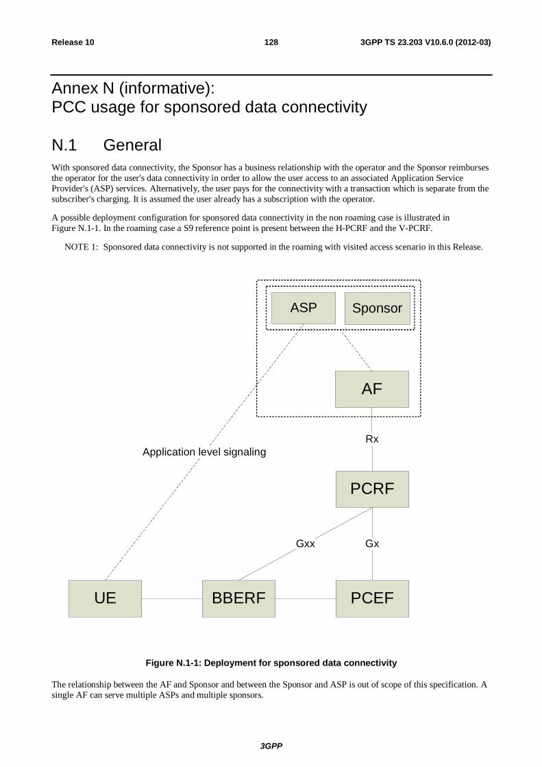
3GPP
3GPP TS 23.203 V10.6.0 (2012-03) 128Release 10
Annex N (informative): PCC usage for sponsored data connectivity
N.1 General With sponsored data connectivity, the Sponsor has a business relationship with the operator and the Sponsor reimburses the operator for the user's data connectivity in order to allow the user access to an associated Application Service Provider's (ASP) services. Alternatively, the user pays for the connectivity with a transaction which is separate from the subscriber's charging. It is assumed the user already has a subscription with the operator.
A possible deployment configuration for sponsored data connectivity in the non roaming case is illustrated in Figure N.1-1. In the roaming case a S9 reference point is present between the H-PCRF and the V-PCRF.
NOTE 1: Sponsored data connectivity is not supported in the roaming with visited access scenario in this Release.
UE PCEF
PCRF
AF
ASP
Gx
RxApplication level signaling
BBERF
Gxx
Sponsor
Figure N.1-1: Deployment for sponsored data connectivity
The relationship between the AF and Sponsor and between the Sponsor and ASP is out of scope of this specification. A single AF can serve multiple ASPs and multiple sponsors.
3GPP
3GPP TS 23.203 V10.6.0 (2012-03) 129Release 10
NOTE 2: An ASP can also be a sponsor.
The sponsor may choose to supply the PCRF (via the AF) with the usage thresholds that it expects the PCEF to enforce. Alternatively, the Sponsor can allow the ASP to enforce such control over the sponsored data connectivity.
N.2 Reporting for sponsored data connectivity There are two deployment scenarios for usage reporting for sponsored data connectivity. The Sponsor Identifier and Application Service Provider Identifier are provided for sponsored services to the PCRF from the AF over the Rx interface.
In the first scenario the PCRF assigns a service specific Charging Key for a sponsored IP flow. The Charging key is used by the PCEF to generate separate accounting records for offline charging and and/or usage data records for online charging for the sponsored flows. Correlation of accounting records and usage data records from multiple users per sponsor and/or application service provider is then performed using the charging key.
In a second scenario the Sponsor Identifier and Application Service Provider Identity is included in PCC-rules from the PCRF to the PCEF as defined in clause 6.3.1. For this scenario the same Charging Key may be used both for IP flows that are sponsored and for flows that are not sponsored. Accounting records generated by the PCEF for offline charging include the Sponsor Identity and the Application Service Provider Identity. Correlation of accounting records from multiple users per sponsor and/or application service provider can then be based on Sponsor Identity and Application Service Provider Identity instead of the Charging Key. Usage reporting for online charging including Sponsor Identity and Application Service Provider Identity has not been specified in this release of the specification. PCC-rules that include a Sponsor Identity and an Application Service Provider Identity should include a Charging Method that indicates offline charging.
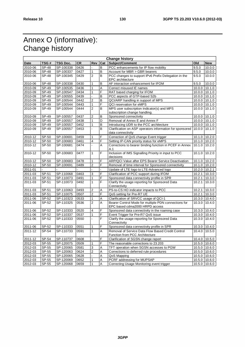
3GPP
3GPP TS 23.203 V10.6.0 (2012-03) 130Release 10
Annex O (informative): Change history
Change history Date TSG # TSG Doc. CR Rev Cat Subject/Comment Old New 2010-06 SP-48 SP-100338 0426 - B PCC enhancements for IP flow mobility 9.5.0 10.0.0 2010-06 SP-48 SP-100337 0427 1 B Account for MBR > GBR bearers 9.5.0 10.0.0 2010-06 SP-48 SP-100345 0429 2 B PCC changes to support IPv6 Prefix Delegation in the
EPC architecture 9.5.0 10.0.0
2010-06 SP-48 SP-100338 0430 1 B AF interaction enhancement for IFOM 9.5.0 10.0.0 2010-09 SP-49 SP-100535 0436 1 A Correct misused IE names 10.0.0 10.1.0 2010-09 SP-49 SP-100547 0434 1 F RAT based charging for IFOM 10.0.0 10.1.0 2010-09 SP-49 SP-100555 0439 - B PCC aspects of GTP-based S2b 10.0.0 10.1.0 2010-09 SP-49 SP-100544 0442 2 B QCI/ARP handling in support of MPS 10.0.0 10.1.0 2010-09 SP-49 SP-100544 0443 1 F QCI reservation for eMPS 10.0.0 10.1.0 2010-09 SP-49 SP-100544 0444 2 B MPS user subscription Indicator(s) and MPS
subscription change handling. 10.0.0 10.1.0
2010-09 SP-49 SP-100557 0437 2 B Sponsored connectivity 10.0.0 10.1.0 2010-09 SP-49 SP-100557 0438 1 D Removal of Annex E and Annex F 10.0.0 10.1.0 2010-09 SP-49 SP-100557 0452 1 B Introducing UDR to the PCC architecture 10.0.0 10.1.0 2010-09 SP-49 SP-100557 0453 - B Clarification on ASP operators information for sponsored
data connectivity 10.0.0 10.1.0
2010-12 SP-50 SP-100691 0459 1 F Correction of QoS change Event trigger 10.1.0 10.2.0 2010-12 SP-50 SP-100683 0461 4 F Setting IP-CAN priority status for eMPS 10.1.0 10.2.0 2010-12 SP-50 SP-100681 0474 - A Corrections to bearer binding function in PCEF in Annex
A.1 10.1.0 10.2.0
2010-12 SP-50 SP-100683 0477 1 F Inclusion of IMS Signalling Priority in input to PCC decisions
10.1.0 10.2.0
2010-12 SP-50 SP-100683 0478 1 F ARP/QCI Value after EPS Bearer Service Deactivation 10.1.0 10.2.0 2010-12 SP-50 SP-100691 0489 2 F Removal of time interval for Sponsored connectivity 10.1.0 10.2.0 2011-01 - - - - - Update of LTE logo to LTE-Advanced logo 10.2.0 10.2.1 2011-03 SP-51 SP-110068 0463 3 F Clarification of PCC support during IFOM 10.2.1 10.3.0 2011-03 SP-51 SP-110073 0491 1 F Sponsored data connectivity profile in SPR 10.2.1 10.3.0 2011-03 SP-51 SP-110073 0492 1 F Clarify the usage reporting for Sponsored Data
Connectivity 10.2.1 10.3.0
2011-03 SP-51 SP-110063 0493 2 A PS-to-CS HO indicator impacts to PCC 10.2.1 10.3.0 2011-03 SP-51 SP-110075 0507 2 F QoS setting for Pre-R7 UE 10.2.1 10.3.0 2011-06 SP-52 SP-110323 0533 1 A Clarification of SRVCC usage of QCI-1 10.3.0 10.4.0 2011-06 SP-52 SP-110325 0536 2 A Bearer Control Mode for multiple PDN connections for
EPC based cdma2000 HRPD access 10.3.0 10.4.0
2011-06 SP-52 SP-110333 0520 4 F Sponsored data connectivity in the roaming case 10.3.0 10.4.0 2011-06 SP-52 SP-110337 0537 1 F Event Trigger for Pre-R7 QoS issue 10.3.0 10.4.0 2011-06 SP-52 SP-110333 0550 - F Clarify the usage reporting for Sponsored Data
Connectivity 10.3.0 10.4.0
2011-06 SP-52 SP-110333 0551 1 F Sponsored data connectivity profile in SPR 10.3.0 10.4.0 2011-12 SP-54 SP-110733 0591 1 A Removal of Service Data Flow Based Credit Control
Function from PCC Architecture 10.4.0 10.5.0
2011-12 SP-54 SP-110737 0608 - F Clarification of SGSN change report 10.4.0 10.5.0 2012-03 SP-55 SP-120075 0509 1 F The reasonable corrections to 23.203 10.5.0 10.6.0 2012-03 SP-55 SP-120065 0581 3 A TFT operation when SGSN accesses to PGW 10.5.0 10.6.0 2012-03 SP-55 SP-120063 0624 2 A Corrections to deferred rule procedures 10.5.0 10.6.0 2012-03 SP-55 SP-120065 0628 - A QoS Mapping 10.5.0 10.6.0 2012-03 SP-55 SP-120069 0652 1 A PCRF addressing for MUPSAP 10.5.0 10.6.0 2012-03 SP-55 SP-120068 0659 1 A Correcting Usage Monitoring event trigger 10.5.0 10.6.0