Embed Size (px)
Citation preview

The Preparatory Survey on the Project for West Java Regional Solid Waste Treatment and Final Disposal Final Report
5-1
5. Legok-Nangka Project Plan
5.1 Design Conditions 5.1.1 Site Condition The proposed project site for Legok Nangka is located on a hillside with the northern area having the highest elevation, sloping down towards the southern side. At some parts of the sight, the slope exceeds 20 percent. The altitude at the lowest southern end of the site is approximately 940 meters, and the highest altitude at the northern end is approximately 1,100 meters. This hill site is composed of volcanic rocks and pumice tuff. As shown in Figure 5-1, the distance from the project site to the closest residences is over one kilometer and affects of waste odor and other issues related to the final disposal site can be considered minimal. The surrounding community is generally in consent of the project, and the minority in opposition has also agreed to the development of the site with the condition that there would be a proper waste treatment facility and sanitary landfill. The local residents are opposed to the waste pickers coming to the site as scavengers, however there has not been any opposing opinions from NGOs so far.
Source: Legok Nangka Environmental Impact Assessment Report, PT. MAZA
Figure 5-1 Project Site Surrounding 5.1.2 Surrounding Infrastructure There are no residences along the access road to the Legok Nangka Project Site, and affects from waste transport vehicles along the access road can be considered minimal. The existing main road passes through the valley and residences in the area conglomerate between the branch road stemming from the main road as well and the springs located at the skirts of the mountains. The volume of traffic on the main road is already large so the increase of waste transport vehicles will not have much affect on issues of noise pollution and vibrations.

The Preparatory Survey on the Project for West Java Regional Solid Waste Treatment and Final Disposal Final Report
5-2
5.1.3 Waste Throughput (Process Amount) Amount of received waste is assumed to be 1000 tons/day as same as the Pre-FS. It is expected that it is possible to receive 1000 tons/day even if recycling of waste may be promoted, since waste generation is increasing as described in chapter 4.1. In case that amount of received waste exceeds 1000 tons/day, it is taken into account that waste is transferred to other landfill or incineration plant under planning. 5.1.4 Waste Material Balance Waste characteristics based on the sampling and analysis data by ITB at Sarimukuti disposal site described in Chapter 4.2 have been assumed. 5.1.5 Annual Operational Days and Operational Hours Waste will be received 360 days per year, which is the same as the Pre-FS. Operation hours will be established individually per facility. 5.2 Technology Selection 5.2.1 Intermediate Treatment Facility As shown in Figure 5-2, the intermediate treatment comprises respective disposal processes of sorting, recycle, and compost.
Source: JICA Survey Team
Figure 5-2 Outline Flow of Intermediate Treatment The received waste is classified to the organic waste and the recyclable one and the residue (non-burnable garbage etc.) as well as Pre-FS. The composting is the most suitable as the organic waste management method in this project as a result of making comparative study from the viewpoint of the environmental impact, the economy, the sustainability, and safety about two or more methods (The evaluation for comparison of the organic waste management method is in Table 5-1). The recyclable one does the recycling use. The residue is transferred to the landfill. The biogas plant that had been examined by the interim report has been decided not to be introduced because the load on the cost side is large.
Sorting
Composting
Landfill
Exported by Provincial
Gov. of West Java
Recycling
Manufacturer
Organic Waste
Residue
Recycles
Waste Received
(Inc. Fresh Market
Waste)

The Preparatory Survey on the Project for West Java Regional Solid Waste Treatment and Final Disposal Final Report
5-3
Table 5-1 Features of Intermediate Treatment Process Environmental
Impact Economic Sustainability Safety Total Evaluation
Composting
A A A A A The smallest impact.
Most economical efficiency with simple facilities and operation
High sustainability if the exporting of the compost is secured *1
Safety established by a lot of experiences in Indonesia and other regions.
Suitable method as organic waste management of this business.
Biogas
A B A A B The negative environmental impact can be suppressed small by consideration in equipment, e.g. installation of the exhaust gas processing system etc.
Economically disadvantage, because of the comparatively high equipment and operating cost,
No matter to be mentioned about the sustainability *2
Safety established by some experiences.
Economically disadvantage compared with composting
RDF
A B B B B The negative environmental impact can be suppressed small by consideration in equipment, e.g. installation of the exhaust gas processing system etc.
Economically disadvantage, because of the comparatively high equipment and operating cost, e.g. drying equipment for high moisture organic garbage
No long-term operation experience of making organic garbage RDF in Japan, because of the safety problem
Safety unestablished yet to make organic RDF
Economically, sustainability and safety disadvantage *3
Incinerator
A B A A B The negative environmental impact can be suppressed small by consideration in equipment, e.g. installation of the exhaust gas processing system etc.
Because of the comparatively high equipment and operating cost, disadvantage in the point of the economy
No problem of the sustainability with steps against the protest campaign *4
Safety established by a lot of experiences in Japan and other regions.
Economically disadvantageous compared with composting
*1: Provincial Government of West Java is describing that they will make contract that all the compost product should be exported by Provincial Gov. of West Java. *2: Actually, some biogas plants (organic refuse) are in operation in Japan. However, the enough training of operation might be necessary in Indonesia. *3: In case of making RDF of plastic, which has comparatively lower moisture than organic, and with the certain receiving organization, it is suitable. *4: If the incinerator is planned to build in West Java, enough steps against negative campaign are necessary. Additional note to Table 5-1: Introduction of the “Anaerobic Digestion Process” Introduction of the “Anaerobic Digestion Process” already adopted in Bali was this time suggested by Indonesian side. Indonesian side insists that the introduction of this technology make it possible to reduce the final waste volume to the landfill and extend the life of landfill. By this technology which was proposed by the Pre-FS also, the waste is temporarily stored in the anaerobic cells where pressure and temperature is controlled. In these cells, methane gas generates during short term and it is utilized for power generation. According to the Pre-FS, in case that waste amount is 400 ton/d, 16 units of anaerobic cells (capacity of each cell is 12 days) are installed, and methane gas production is completed in 180 days. After 180 days, the waste is transferred to the compost maturation zone. We evaluated this “Anaerobic Digestion Process” and concluded that it is difficult to adopt it for the following reasons.
1) As for the “Anaerobic Digestion Process”, we do not possess technology nor experience in Japan. Therefore, we cannot adopt this process with scientific proof.
The Preparatory Survey on the Project for West Java Regional Solid Waste Treatment and Final Disposal Final Report
5-4
2) We investigated the operating results in foreign countries concerning the “Anaerobic Digestion Process”. However, we could not find the reliable data.
3) It is estimated that small amount of gas will generate during a short term of around 180 days. 4) According to the Pre-FS, compost maturation zone also necessary. It is disadvantageous to adopt such
technology in the site where area is limited.
Therefore, we excluded this technology in Table 5-1.
The proposed Intermediate Treatment Process fully satisfies the following requirements as per Article 30 of Regional regulation of the province of West Java (November 12, 2010).
• To classify • Composting/Utilization of Compost for Fertilizer • Recycling and / or Production
Supplementary explanation regarding the composting:
• Based on meeting result with West Java Provincial Government, composting periods is set 20 days and West Java Provincial Government guarantees the taking-over of the ownership of compost products. In this regards, West Java Provincial Government acknowledges; All of the 20day-compost is taken away everyday to the Government with a burden on the Government.
• Due to such period of compost process (20 days), there are possibilities that the compost products do not satisfy a required quality specified in the standard of composting in Indonesia. The compost might be still premature or on the way to decompose.
• There are possibilities that hazardous waste including medical wastes contains compost products
To fulfill the consensus with the government and the relevant standard, a windrow turner and a screen are to be used in the composting to get the compost quality efficiently better. 5.3 Basic Design 5.3.1 Outline (1) Process Flow and Material Balance of Whole Facility Received wastes are to be classified and treated upon considering actual sorting operation as shown in Table 5-2. “iv) waste other than above” and residue separated in the composting unit is buried into the landfill. They are compacted to half-one volume using landfill compactor in order to expand project life of the landfill. Flow-sheet/material balance is as shown in Figure 5-3. In this figure, life of landfill also indicated.

The Preparatory Survey on the Project for West Java Regional Solid Waste Treatment and Final Disposal Final Report
5-5
Table 5-2 Classification and Disposal of Received Waste Classification Sort of Waste Treatment
i) Organic Waste (sourced from those other than the above)
• Organic + Leaves/Garden • Plastic under 50mm • Paper • Residues (supposed to be organic)
Composting => Exported by Provincial Gov. of West Java
ii) Recyclable Metal and so on.
• Metal Recycling
ii) Recyclable Plastics • Recyclable Plastic Recycling (Note-1)
iv) Waste other than above
• Non recyclable plastic • Minerals • Disposal Nappies • Composites • Textile • Rubber • Others
Landfill (Compacted using landfill compactor)
v) Hazardous Waste • Hazardous wastes (medical, electrical, electronic, harmful)
Temporary storage Then exported and processed in an external organization. (Note-2)
Note-1: Recycling of plastic Recyclable plastic will be sold to recycling manufacture after classified. The recycling manufacture classifies them again by quality and by color at its factory. Then, after such process as machine crush, washing, and pelletizing, it carries into the plastics processing plant of the inside and outside of Jawa, and makes it a reuse article. Note-2: Outsourcing of hazardous waste treating Treatment of hazardous waste will be outsourced to the PPLi. The business activities of the PLLi are 1) stabilizing treatment of hazardous waste, 2) land-filling, 3) Liquid waste treatment, and 4) site clean-up. The hazardous wastes carried into PLLI will be treated by stabilization process, which involves chemical pre-treatment followed by a mixing process involving Portland cement, absorbed clay, water and other reagents in varying proportions to create stable substances.

The Preparatory Survey on the Project for W
est Java Regional Solid Waste Treatm
ent and Final Disposal
Final Report
5-6
Figure 5-3 Flow-Sheet/Material Balance

The Preparatory Survey on the Project for West Java Regional Solid Waste Treatment and Final Disposal Final Report
5-7
(2) Whole Facilities Site Plan The outline of the plan is shown below and the overall layout plan is shown in Figure 5-4 and 5-. 1) In the earthwork plan in the project area, the ground level in the connecting portion of
southern access road is EL965 m which is the same as the Pre-FS planned EL.
2) The area of each facility, landfill zone will be constructed gradually like the shape of staircase from south to north according to the topography in the planned area which has the three zones from south side, 1.Lower part. Planned EL: EL985 m, Regulation reservoir (Area; 1.2 ha) and Reserve area (Area; 1.34 ha). 2. Middle part. Planned EL: EL1020m, Compost Zone (Area; 2.00 ha), Sorting Zone (Area; 1.6 ha), Seepage water treatment facility (Area; 0.5 ha) and Seepage reservoir (Area; 1.0 ha). 3. Upper part Landfill Zone.
3) Perimeter road will be constructed around the facility and the width of the access road to each facility and the width of the perimeter road around the landfill is 10 m and 6 m respectively.
4) The earth work volume is “Cut; 1,963,000 m3, Fill; 1,075,000 m3, the balance; 888,000 m3 (inclusive of earthwork at landfill). There is other balance soil, i.e. road earth work, excavated volume for regulating reservoir for seepage water and regulating reservoir, which are necessary to study the countermeasure including the use of the soil the use as molding.
5) Although the balance soil can be used as molding, there is no space for the temporary stock yard for it. Regarding this issue, we have obtained the provisional agreement of the new yard beside the landfill site for the purpose of temporary stock yard for molding soil from West Java Government during interim report. Therefore, the temporary stock yard for molding has been assumed within 1km from current existing land. Only the disposal fee for the balance soil during the construction for the molding are added in the quotation for the estimated project cost in the final report. Regarding the construction cost for temporary stock yard for earthwork, access road for construction, land fee and other expenses, which are not included into this estimated project cost, will be paid by West Java Government.
6) The regulating reservoir is planned to construct in the viewpoint of disaster prevention despite the fact that there is no clear local legal restriction in terms of the construction of the regulating reservoir in the large-scale development and the local Pre-FS plan are also not included in such a restriction
(3) Circulation Plan Circulation plan is indicated in Figure 5-6. .

The Preparatory Survey on the Project for W
est Java Regional Solid Waste Treatm
ent and Final Disposal
Final Report
5-8
Figure 5-4 Overall Layout Plan (Plan View)

The Preparatory Survey on the Project for W
est Java Regional Solid Waste Treatm
ent and Final Disposal
Final Report
5-9
Figure 5-5 Overall Layout Plan (Section View)

The Preparatory Survey on the Project for W
est Java Regional Solid Waste Treatm
ent and Final Disposal
Final Report
5-10
Figure 5-6 Circulation Plan

The Preparatory Survey on the Project for West Java Regional Solid Waste Treatment and Final Disposal Final Report
5-11
5.3.2 Sorting (1) Process Flow Process flow and material balance of sorting system is shown in Figure 5-7.
Flow Sheet of Garbage Separating Plant(Legok)
Organic Matter Yard(for Compost)
Valuable Plastic Yard(for Sale)
Metal Yard(for Sale)
Other Garbage Yard(to Landfill)
Container
φ50
OrganicPaper
Recycable Plastic
Other Garbage &Unrecycle Plastic
Metal
Hazardous Material
Box Receiving
Box Receiving
Compacting・Packing
φ50
Collected Garbage(1,000 t/day)
Hazardous Material
Under50mm
Crushing system(4units)
Hand sorting Convair(4units)・Worker:30persons/units・Length:25m・Wide:1,200mm・Garbage hight:200mm
Hand sorting Convair(2units)
Hand sorting Convair(2units)
Trommelsorting machine(1unit)
Trommelsorting machine(1unit)
Figure 5-7 Process Flow of sorting system i) Receive and feeding system The garbage delivered by garbage trucks is pooled in receiving yard and then dumped to receiving hopper by heavy equipment. The dumped waste is fed to separating service. ii) Separating system The waste from ‘Receiving and feeding system’ is classified by the machine by particle size. The smaller one is mainly organic. The small size waste is fed to conveyance system, and the over size waste is fed to manual sorting system. In the manual sorting system, the waste is separated to 5 kinds of waste. Recyclable plastic → for sell Non- Recyclable plastic Others(Impossible to separate)
→ To Landfill
Organic (kitchen waste, papers, leaves) → Under 50 mm by Shredder, feed to composting system Metal → for sell Hazardous, medical, etc → To outside
iii) Conveyance System The separated waste should be fed to storage system.

The Preparatory Survey on the Project for West Java Regional Solid Waste Treatment and Final Disposal Final Report
5-12
iv) Storage System The fed waste should be stored in storage area. v) Dust Collection System To keep the working environment clean, the dust around workers and equipments should be collected and exhausted to atmosphere through the dust collector and the blower. vi) Common Service Dust collector needs compression air to backwash filter, so the compressor should be equipped. Further more, the plant water feed and discharge pump should be equipped. (2) Component Equipments, Processing Capacity Main constructing facilities are shown as below (Capacity of these facilities will be mentioned in final report). Besides, operating time and annual operating days are shown in Table 5-3.
Table 5-3 Operating Time and Annual Operating Days System, service Operation time Annual Operating Days Receive and feeding system 7 days/week, 16 hours/day 360 days Separating system 7 days/week, 12 hours/day 360 days Feeding system 7 days/week, 12 hours/day 360 days Storage system 7 days/week, 12 hours/day 360 days Dust collection system 7 days/week, 12 hours/day 360 days Common service 7 days/week, 12 hours/day 360 days
i) Receive and feeding system
Receiving yard Structure : Reinforced concrete construction Receiving hopper Type : Direct dumping Units : 2 Feeding conveyor Type : Apron conveyor Units : 2
ii) Separating system
Screening by size Type : Trommel (φ50mm) Units : 2 Manual sorting conveyor Type : Belt conveyor Units : 4 Shredder for compost Type : Single shaft Shredder Disposal capacity : 7.2 t/hr/unit Units : 3
iii) Feeding system
Feeding conveyor Type : Belt conveyor Units : 20
iv) Storage system Storage yard Structure : Reinforced concrete construction

The Preparatory Survey on the Project for West Java Regional Solid Waste Treatment and Final Disposal Final Report
5-13
v) Dust collection system Dust collector Type : Bag filter with Automatic backwash Disposal capacity : 1,000 m3/mim Units : 1 Blower Type : Turbo fan Disposal capacity : 1,000 m3/mim×4.0 kPa Units : 1
vi) Common service
Compressor Type : Lubricant supply Disposal capacity : 3.6 m3/min×0.83 Mpa Units : 1 Deodorize-insect proof equipment Type : pressure spraying type Disposal capacity : 18.0 l/min×1,471 kPa Units : 1
vii) Others
Heavy-equipment Type : wheel loader Capacity : 5.6 m3/bucket Units : 4
Figure 5-8 Legok Nangka Facility Layout

The Preparatory Survey on the Project for West Java Regional Solid Waste Treatment and Final Disposal Final Report
5-14
5.3.3 Compost (1) Process
1. The organic waste sorted as described in section 5.3.2 is transported by dump trucks to a windrow hall and piled up trapezoid in cross section by wheel loaders.
2. The windrow stands in the building for 20 days for the natural process of decomposition of the organic matter and is turned from time to time by a windrow turner.
3. The compost after 20 days decomposition is screened and taken out by dump trucks employed by WJPG.
(2) Building and Equipments 1. Windrow Hall a floor space of 20,000 square meters 2. Wheel loaders: 7 units 3. Dump trucks: 10 units 4. Windrow turner: 1 unit 5. Screen: 1 unit
(3) Compost Hall Drawings

The Preparatory Survey on the Project for W
est Java Regional Solid Waste Treatm
ent and Final Disposal
Final Report
5-15
Figure 5-9 Compost Building Plan

The Preparatory Survey on the Project for W
est Java Regional Solid Waste Treatm
ent and Final Disposal
Final Report
5-16
Figure 5-10 Compost Building Cross Sections

The Preparatory Survey on the Project for W
est Java Regional Solid Waste Treatm
ent and Final Disposal
Final Report
5-17
Figure 5-11 Compost Building Foundations

The Preparatory Survey on the Project for W
est Java Regional Solid Waste Treatm
ent and Final Disposal
Final Report
5-18
Figure 5-12 Compost Building Roof Plan

The Preparatory Survey on the Project for W
est Java Regional Solid Waste Treatm
ent and Final Disposal
Final Report
5-19
Figure 5-13 Compost Building Foundation Details

The Preparatory Survey on the Project for West Java Regional Solid Waste Treatment and Final Disposal Final Report
5-20
Scientific Basis for Fremantation Period for Compost The relation between the necessary days for composting and effect of activator can be referred to a study in Indonesia, which reports experiment of compost producing using activator in Sukuna Village in Sleman Regency with statistical validation. Usually, it takes a few months for whole composting process without activator, and generally it was known the activator enables to shorten the time up to 2 weeks, however, the exact effect by the density of activator were unknown. Here, application of activator were changed from 15ml/L to 75ml/L, and adopted it to 9 composting samples. The result shows that the average necessary composting days were 11.22 days for 75ml/L, and 18.11 days for 15ml/L. Consequently, the it can be expected that the necessary time for composting process with activators would be less than 20 days even the density of activator comes less. Note that the activator cost will be covered by the WJPG. Source: SP Ganefati, 2008, Dosis efektif inoculant cair untuk mempercepat waktu pengomposan sampah organik
5.3.4 Sanitary Landfill Landfill facility should be designed to store and keep Waste safely without any flowing or sliding out, and also be designed to prevent any leachate from the Waste running out and contaminate outside land and underground water. (1) Type of Landfill
• Landfill should be open type and managed as Sanitary Landfill. The type of the Final Landfill Site is roughly divided into two type, Open type and Closed System Type. In this case, we selected Open type considering of required huge volume of waste material during over ten years (estimated roughly more than 1,220,000 m3).
(2) Site Formation
• Site Formation should be designed with consideration of balancing cut/fill volume in their earth works.
• However, in the Legok-Nangka, maximizing the area for landfill is the first priority to store waste up to the amount required. For the result of it, there is no space to keep the cut material for covering waste in the designated site. When the interim report has been submitted and explained, it was agreed between West Java Government and us that an adequate additional area near by the site (within 1km distance) shall be provided by West Java Government for keeping cut material as covering soil of waste.
• Therefore, it is requested to provide flat land to keep the material as covering soil close to the site.
• For controlling of the quality and the amount of the leachate, the landfill area should be divided a certain blocks to fit the capacity of the leachate treatment Facility.
• In the landfill blocks, not in their operations, surface water should be collected and removed out by utilizing the deference of level of the area.
• And for the landfill block after its operation, all surface exposed should be covered with impermeable sheets so that surface water does not run into the waste layer for the purpose that the burden to the leachate facility can be reduced.
• The facility is designed to discharge the leachate by gravity into the existing waterway after the whole landfill operation is completed.
1) Total Landfill area: 12.8 ha 2) Slope grade: Cut 1:1.5 to 1:1.8, fill 1:2.5 to 1:3.0

The Preparatory Survey on the Project for West Java Regional Solid Waste Treatment and Final Disposal Final Report
5-21
Figure 5-14 Plan of Site Formation & Landfill Area
Landfill Area
Surface Water Regulating Reservoir

The Preparatory Survey on the Project for West Java Regional Solid Waste Treatment and Final Disposal Final Report
5-22
(3) Landfill Liner (Impermeable Layer) Impermeable Layer should be constructed to prevent the leachate leaking out and contaminating the environment around there.
• Structure of the Impermeable Layer: Dual Impermeable Sheeting to be adopted. The structures of the sheeting are as follows,
Table 5-4 Sealing Works Flat area Slope area up down
- Permiable Layer (Gravel material) t = 40cm - Protection soil Layer t = 50cm - Protection Mat (short fiber non woven) t = 10mm - HDPE Sheet t = 1.5 mm - Protection Mat (short fiber non woven) t = 10mm - HDPE Sheet t = 1.5 mm - Protection Mat (short fiber non woven) t = 10mm - Protection soil Layer (Cut material on site) t = 50 cm
- Protection soil Layer (Operation stage) t = 50 cm
- Protection Mat (Long fiber non woven) t =4.5 mm - HDPE Sheet t = 1.5 mm - Protection Mat (short fiber non woven) t = 10mm - HDPE Sheet t = 1.5 mm - Protection Mat (short fiber non woven) t =10 mm - Protection gunite-shooting t = 10 cm
(4) Underground Water Collection and Removal Facility Underground water collection and removal facility should be installed for the purpose that the impermeable layer should be secured from any damage which is likely to be caused by up-lift pressure of the underground water. Also when the level of the underground water rise up during rainy season, it may have the existing ground be loose or slide out with its pressure, therefore the working efficiencies of construction equipment are also affected during construction in such condition. It is expected that to monitor the quality of the underground water removed from the landfill area will indicate any contamination if leachate leakage has been occurred.
• Drainage pipeline of the underground water should be installed with adequate
horizontal distance from the pipeline of the leachate correction. • The drainage pipeline should be designed with adequate durability. • Diameter and quality of the drainage pipeline should be selected according to the
result of the hydraulic analysis and/or structural calculation.
Trunk line: perforated HDPE pipe (double wall type) φ200 mm Branch line: drainage mat W = 300 mm
• The underground water collected through the facility should be discharged out by
gravity at the final collection pit.

The Preparatory Survey on the Project for West Java Regional Solid Waste Treatment and Final Disposal Final Report
5-23
Figure 5-15 Plan of Underground Water Collection and Removal Facility
(5) Surface Water Collection and Removal Facility Surface water collection and removal facility should be designed in following aspects. Surface water in the landfill area, not in its operation, should be collected and removed immediately to avoid flowing into the landfill operation block. The volume of the leachate should be controlled within the capacity of the treatment facility, and therefore adequate drainage system should be designed and arranged in their right position.
• U-shaped ditch should be installed along the perimeter of the landfill area to correct the surface water from the surrounding area and to remove to the Regulating Reservoir.
Main drainage: U-shaped ditch 300 × 300 mm to 1,200 × 1,200 mm Final Drainage to the regulating reservoir: HDPE (or RC) Pipe φ1,000 mm
• The surface water in the landfill area, not-operation, below EL.1020 should be removed out through the underground pipeline leading to the downstream side of the landfill area.
• The underground pipeline should be plugged when the landfill operation reach up to it’s inlets level.
Drainage facility in landfill area: U -shaped ditch 300x300mm Drainage pipeline in landfill area: HDPE pipe φ300 to φ400mm
Final Collection Pit (for monitoring)

The Preparatory Survey on the Project for West Java Regional Solid Waste Treatment and Final Disposal Final Report
5-24
• The size of the U-shaped drainage should be designed in accordance with their hydraulic analysis.
The regulating reservoir to be designed in accordance with a Japanese standard “Technical standards for Regulating Reservoir etc.” published by Japan river.
Figure 5-16 Plan of Rainwater Drainage Facility
Surface Water Regulating Reservoir
Surface Water Catch Pit (from the area below EL1021)

The Preparatory Survey on the Project for West Java Regional Solid Waste Treatment and Final Disposal Final Report
5-25
(6) Leachate Collection and Removal Facility Leachate should be collected and removed as quickly as possible, preventing it from stagnating in the waste material and make it easier for fresh air to penetrate, thereby promoting aerobic condition in the waste layers. Also the leachate collection and removal facility is installed for the purpose that the structural burden against the impermeable sheet and the storage dam due to the leachate water pressure can be reduced.
• The Leachate collection and removal facility is designed based on the data of rainfall in
Bandung City during 1994 to 2008.
• The space of collection pipelines, diameter of the pipeline should be determined considering its efficiency and aerobic condition in the waste layers. And the shape of filter materials of the pipeline should be decided preventing blockage with sediment/scales. The pipeline should be laid on the depressed liner putting filter materials between the pipeline and the liner to promote seepage efficiency. The pipeline should have adequate durability and strength. Trunk line: perforated HDPE pipe (double wall type) φ400 to φ600mm
• Branch line: perforated HDPE pipe (double wall type) φ200mm
• The protection soil layer for the liner sheet should be adequately compacted and a non woven geotextile should be inserted along the contact plane between the soil layer and the filter material surrounding the pipeline to prevent the soil piping into the filter material.
• Leachate should be gathered into the final catch pit located at the lowest point of the landfill area and pumped out to the leachate reservoir.
• When the last drainage pipeline to the final catch pit being installed, it is necessary to break trough the liner sheet, therefore the sealing work at the break trough point should be carefully done to prevent any leakage of leachate to outside.

The Preparatory Survey on the Project for West Java Regional Solid Waste Treatment and Final Disposal Final Report
5-26
Figure 5-17 Plan of Leachate Collection and Removal Facility
(7) Gas Collection and Removal Facility Gas should be ventilated immediately through pipelines, thereby promoting aerobic condition in the waste layers.
• The gas collection and removal system shares the pipelines of leachate collection and
removal facility, therefore adequate capacity of the pipelines should be required. • The specifications of the pipes are as follows,
Vertical Ventilation Pipe: perforated HDPE pipe (double wall type) φ600mm Ventilation Pipe on Slope: perforated HDPE pipe (double wall type) φ200mm
(8) Monitoring of Underground Water During the landfill operation until closing the business, underground water should be monitored periodically whether any environmental impacts are caused by the landfill operation. The monitoring well should be installed in at least two locations.
• The monitoring wells should be kept in sheds securing from storm and the third party.
Monitoring Well: PVC pipeφ100mm in two locations
Final Catch pit of Leachate
Leachate Reservoir

The Preparatory Survey on the Project for West Java Regional Solid Waste Treatment and Final Disposal Final Report
5-27
(9) Anti-Scattering Fence and Gate Fence surrounding the landfill area should be installed to prevent the waste scattering to outside. 5.3.5 Leachate Treatment (1) Basic Policy for the Plan
The proposed leachate treatment facility shall be designed under the following functions as solutions for issues in the Pre-Feasibility Study. 1. The function is to discharge the treated water to the large river secured enough amount of
water around one year, the lower river than the spring water around the landfill facility, not to sprinkle on the green-belt area. The treated water, maximum 240 L per minute, is to be discharged to the assumed large river from the effluent tank in the leachate treatment facility through the plumbing, 150mm in diameter by gravity flow. The length of plumbing is approximately 10km, and the method of construction for the plumbing would be the under-grounding piping on a roadside, the grounding piping, and the piping under the bridge. The West Java State Government agreed that the planning, the construction, and the cost allocation should be executed by the state government. The concept of the Closed System, moreover, should be taken to limit the influence of the treated water; therefore, the following measures shall be adapted. Those measures would secure approximately 50% of the expected system. While the amount of leachate is 340 m3 per date in case of covering a sheet, the amount of it is 620 m3 per date in case of non-covering; therefore, 45% of reduction would be realized. The purified water of the equipment employed in the leachate treatment facility; furthermore, the treated recycled water would be used; therefore, the discharging water 60 m3 per date could be reduced comparing to use tap water. Those measures would secure approximately 50% of the expected system.
The reduction measure for quantity of leachate would be planed by the surface
exclusion of rainwater coving a sheet on a finished landfill-block. In addition, the reduction measure for the outflow discharge of the treated water
would be planned by re-using the treated water. 2. Appropriate quantity of capacity of the regulation pond and daily quantity of leachate
would be determined based on the analyzed meteorological data: 1994 to 2008 and the planning which the un-treated leachate shall not be discharged to the public water area even in the rainfall season.
3. The function is that leachate in the regulation pond is sent back to the vent sticking out the
landfill (vertical gas venting facility) and contaminant would be purified by microbe inhabiting in the inside of the landfill. Therefore, load of the leachate treatment facility could be reduced and the risk-reduction for environmental influence could be expected.
4. The function is to fill up the floating carriers keeping microbe in the biological response
tank and keep stability and high-efficiency for the treatment.

The Preparatory Survey on the Project for West Java Regional Solid Waste Treatment and Final Disposal Final Report
5-28
Source: Environmental Bureau, Fukuoka City (part modified)
Figure 5-18 Mechanism of Semi-aerobic Landfill: Fukuoka Method
Figure 5-19 Imaged Floating Carries

The Preparatory Survey on the Project for West Java Regional Solid Waste Treatment and Final Disposal Final Report
5-29
(2) Block Flow
Figure 5-20 Block Flow for Leachate Treatment Facilities
(3) Instrument and Treatment Capacity i) Processing Waste Water Leachate of Domestic Waste Landfill & Miscellaneous Wastewater: Miscellaneous Wastewater means the waste water happened in the sludge concentration process for letting the sludge settle and concentrating it, the dehydration process for dehydrating the sludge, and the backwashing process for protecting the plugging in the sand filter etc.
The Preparatory Survey on the Project for West Java Regional Solid Waste Treatment and Final Disposal Final Report
5-30
It is assumed that contamination is not contained in the quality of Miscellaneous Wastewater. The reasons are following;
• All contamination flowing in the leachte treatment facility income from leachate. • Additional contamination is not entered from the outside in the occurring process of
Miscellaneous Wastewater.
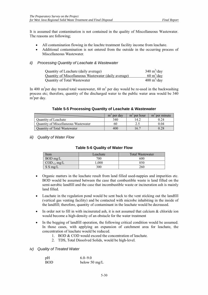
ii) Processing Quantity of Leachate & Wastewater
Quantity of Leachate (daily average) 340 m3/day Quantity of Miscellaneous Wastewater (daily average) 60 m3/day Quantity of Total Wastewater 400 m3/day In 400 m3per day treated total wastewater, 60 m3 per day would be re-used in the backwashing process etc; therefore, quantity of the discharged water to the public water area would be 340 m3per day.
Table 5-5 Processing Quantity of Leachate & Wastewater m3 per day m3 per hour m3 per minute Quantity of Leachate 340 14.2 0.24 Quantity of Miscellaneous Wastewater 60 2.5 0.04 Quantity of Total Wastewater 400 16.7 0.28
iii) Quality of Water Flow
Table 5-6 Quality of Water Flow Item Leachate Total Wastewater BOD mg/L 700 600 COD Cr mg/L 1,000 850 S S mg/L 300 260
• Organic matters in the leachate result from land filled used-nappies and impurities etc.
BOD would be assumed between the case that combustible waste is land filled on the semi-aerobic landfill and the case that incombustible waste or incineration ash is mainly land filled.
• Leachate in the regulation pond would be sent back to the vent sticking out the landfill (vertical gas venting facility) and be contacted with microbe inhabiting in the inside of the landfill; therefore, quantity of contaminant in the leachate would be decreased.
• In order not to fill in with incinerated ash, it is not assumed that calcium & chloride ion would become a high-density of an obstacle for the water treatment
• In the begging of landfill operation, the following critical condition would be assumed. In those cases, with applying an expansion of catchment area for leachate, the concentration of leachate would be reduced.
1. BOD & COD would exceed the concentration of leachate. 2. TDS, Total Dissolved Solids, would be high-level.
iv) Quality of Treated Water
pH 6.0–9.0 BOD below 50 mg/L

The Preparatory Survey on the Project for West Java Regional Solid Waste Treatment and Final Disposal Final Report
5-31
COD below 100 mg/L S S below 100 mg/L
• There are no appropriate disposal-standards for a leachate treatment facility; therefore, the standard “Industrial Plant 1” shall be applied. The three items, NH3, NO2 & NO3, however, would be excluded since the discharging river is not a river under the closed water area.
v) Treatment Flow
• Polluted Water Treatment - Inflow Regulation + Biological Treatment + Coagulating Sedimentation Tank +
Advanced Treatment (Sand Filter Treatment + Activated Carbon Treatment + Chelate Treatment) + Disinfection & Re-Use
- In order not to fill in with incinerated ash containing many calcium & chloride, the treatment for calcium & chloride ion would not be practiced.
- The floating carriers are filled up in the biological response tank, the biological treatment, and stability and high-efficiency for the treatment would be designed.
- After the biological treatment, the combined process treatment; the coagulating sedimentation, the sand filter, the activated carbon treatment, and the leachate treatment are designed for treating the refractory COD, the color, and the heavy metal.
• Sludge Treatment
- Landfill disposal after concentration & dehydration
vi) Calculation for Quantity of Leachate • Selection of Meteorological Data
- The meteorological data: 1996, the maximum rainfall year and the maximum monthly precipitation, would be employed in the meteorological data from 1994 to 2008 for calculating the quantity of leachate.
- Annual Precipitation 2,790 mm
• Leachate Coefficient - Leachate Coefficient (landfill operation) 0.72 - Calculated by the method of Blaney Criddle - Leachate Coefficient (finished landfill ) 0.10 - Leachate Coefficient could be reduced from 0.33 to 0.10 by covering a sheet on
the surface and excluding most of rainfall water; moreover, quantity of leachate could be restrained.
• Determination of Conversion Area
- Maximum Conversion area would be determined by calculating the conversion area on each landfill order based on the leachate coefficient and the landfill area. The maximum conversion area is 28,600 m2, and the landfill area is: Finished Landfill Area: 59,900 m2 & Operated Landfill Area: 31,400 m2.
• Calculation between the Quantity of Leachate and the Maximum Capacity Regulation
- Table 5-7 is acquired the relationship between the quantity of leachate which should be treated in one day and the maximum capacity regulation for protecting overflow based on the daily precipitation of 1996 & the maximum conversion area. The relationship between the quantity of leachate and the maximum capacity regulation is that the more the quantity of daily treated leachate-capacity increases, the more the quantity of non-treated & saved leachate decreases; as a result, the

The Preparatory Survey on the Project for West Java Regional Solid Waste Treatment and Final Disposal Final Report
5-32
maximum capacity regulation would be reduced. In experiences based on profitability with construction, workability & profitability with maintenance, and area-condition etc, both appropriate ratio is 340 m3 per day, the quantity of leachate on Table 5-7 since the figure, the maximum capacity regulation divided by the quantity of leachate, is mainly adapted approximately 50 days as a standard.
- The required capacity of regulation pond in the case mentioned above, therefore, should be over 17,400 m3.
Table 5-7 Relationship between the Quantity of Leachate and the Maximum Capacity Regulation
Quantity of Leachate ( m3 per day)
Maximum Capacity Regulation (m3)
Maximum Capacity Regulation / Quantity of Leachate (day)
280 21,549 77.0 300 20,149 67.2 320 18,749 58.6 340 17,354 51.0 360 16,397 45.5 380 15,577 41.0 400 14,757 36.9 420 13,937 33.2 440 13,117 29.8 460 12,447 27.1

The Preparatory Survey on the Project for West Java Regional Solid Waste Treatment and Final Disposal Final Report
5-33
(4) Plot
Figure 5-21 Ground Floor Plan

The Preparatory Survey on the Project for West Java Regional Solid Waste Treatment and Final Disposal Final Report
5-34
Figure 5-22 Second Floor Plan

The Preparatory Survey on the Project for West Java Regional Solid Waste Treatment and Final Disposal Final Report
5-35
Figure 5-23 Cross Section

The Preparatory Survey on the Project for West Java Regional Solid Waste Treatment and Final Disposal Final Report
5-36
5.4 Project Implementation Plan 5.4.1 Sorting (1) Construction This facility should be constructed economically and safety based on design concept. Therefore, we need to plan with regarding site condition and the progress of the construction. In addition, we need keep applicable laws and regulations in construction.
(2) Construction management plan Work process plan
Prior to start of the construction, make a work process plan and arrange it to a progress schedule. The work process plan makes a week or a monthly progress schedule for every works, and it is important to assume the detailed examination with the network process.
General construction plan
Prior to start of the construction, we need to make the general construction plan. The construction plan needs to gather up about a procedure and a method of construction as follows. (It’s need to revise by contents of the construction appropriately.)
1.Construction summary 2.Plan progress schedule 3.The site organization system 4.Safety management 5.Designated machine 6.Main material 7.Construction method (Include a main machine, a temporary plan, a construction site)
8.Construction management plan 9. The emergency system and correspondence 10.Traffic management 11.Environmental measures 12.Maintenance of the site work environment 13.Industrial waste disposal method
In addition, the construction plan shoule be enough considered each time schedule of engineering works, building works, machinery production, installation construction, electricity construction, other construction. And we should plan with considering of the condition of construction, and the plan should be safety and economical. Construction contents in sorting facility
• Machinery apparatus installation • The piping, duct work • Electric instrumentation work
Each equipment should be manufactured by based on the design document in a factory and transported to site and installed. The method of movement and installation in indoor should be selected such as the hang crane or the roller pull. It should be considered carefully, should not damage each equipment in transfer and installation. In addition, temporary works, site assembling, welding and painting should be worked out according to the design document. The equipments must be run without trouble.
Construction schedule (plan)
The sorting process is shown in the figure below with color.

The Preparatory Survey on the Project for West Java Regional Solid Waste Treatment and Final Disposal Final Report
5-37
1 Mobilisation2 Setting Out Work3 RC Wall
Excavation & Lean concreteReinforcementForm workConcrete
4 Pit & Drain PitExcavationGravel layingLean Concrete BaseWall
5 Working Stage -35.0mx27.5mExcavationGravel & Lean ConcreteConcrete Partition Wall
6 Slab -80.0x40.0m and 80.0x30.0mExcavationGravel Concrete
7 Equipment installation8 Electorical work9 Commissioning
10 Access11 Roof Structure
ExcavationGravel & Lean concreteFoundation ConcreteSteel Structure installationRoofing Sheet
145 12 13 166 7 8 9 10 11 15
WORK SCHEDULE FOR THE SORTING FACILITY BUILDING CONSTRUCTIONLEGOK NAGKA SOLID WASTE MANGEMENT PLANT, WEST JAVA , INDONESIA
S No DESCRIPTION MONTHS1 2 3 4
Figure 5-24 Construction Schedule (Plan) for Sorting Facility
[Construction of Building for Sorting] (1) Introduction This method statement describes the procedures for Sorting Building Construction Works. The Sorting building consists of a receiving facility, sorting facility, transport facility, storage yard, dust collection facility and common facility. Some facilities will be covered by roof structure. The major items and construction schedule as shown below (2) Major Items The major item civil works for the construction of Sorting Facility building includes the following items:
1. Foundation for ingress access road, receiving yard and storage yard 2. Retaining wall for the receiving yard and storage yard. 3. Working platform. 4. Transfer pit and drainage pit. 5. Equipment installation. 6. Electrical work. 7. Access road. 8. Steel roof structure.

The Preparatory Survey on the Project for West Java Regional Solid Waste Treatment and Final Disposal Final Report
5-38
(3) Program
1 Mobilisation
2 Setting Out Work
3 RC Wall
Excavation & Lean concrete
Reinforcement
Form work
Concrete
4 Pit & Drain Pit
Excavation
Gravel laying
Lean Concrete
Base
Wall
5 Working Stage -35.0mx27.5m
Excavation
Gravel & Lean Concrete
Concrete
Partition Wall
6 Slab -80.0x40.0m and 80.0x30.0m
Excavation
Gravel
Concrete
7 Equipment installation
8 Electorical work
9 Commissioning
10 Access
11 Roof Structure
Excavation
Gravel & Lean concrete
Foundation Concrete
Steel Structure installation
Roofing Sheet
145 12 13 166 7 8 9 10 11 15S No DESCRIPTION MONTHS
1 2 3 4
Figure 5-25 Program for Construction of Building for Sorting
(3) Layout Plan and Sections
Figure 5-26 Plan

The Preparatory Survey on the Project for West Java Regional Solid Waste Treatment and Final Disposal Final Report
5-39
Figure 5-27 Sections
[Other Construction Related to Sorting Facility] (1) Construction This facility should be constructed economically and safety based on design concept. Therefore, we need to plan regarding site condition and the progress of the construction. In addition, we need keep applicable laws and regulations in construction. (2) Construction Management Plant Work Process Plan
Prior to start of the construction, make a work process plan and arrange it to a progress schedule. The work process plan makes a week or a monthly progress schedule for every works, and it is important to assume the detailed examination with the network process. General Construction Plan
Prior to start of the construction, we need to make the general construction plan. The construction plan needs to gather up about a procedure and a method of construction as follows (it’s need to revise by contents of the construction appropriately).
1. Construction summary 2. Plan progress schedule 3. The site organization system 4. Safety management 5. Designated machine 6. Main material 7. Construction method (Include a main machine, a temporary plan, a
construction site)
8. Construction management plan 9. The emergency system and correspondence 10. Traffic management 11. Environmental measures 12. Maintenance of the site work environment 13. Industrial waste disposal method

The Preparatory Survey on the Project for West Java Regional Solid Waste Treatment and Final Disposal Final Report
5-40
In addition, the construction plan should be enough considered each time schedule of engineering works, building works, machinery production, installation construction, electricity construction, other construction. And we should plan with considering of the condition of construction, and the plan should be safety and economical. Construction Contents in Sorting Facility
• Machinery apparatus installation • The piping, duct work • Electric instrumentation work
Equipment should be manufactured based on the design document in a factory and transported to site and installed. The method of movement and installation in indoor should be selected such as the hang crane or the roller pull. It should be considered carefully, should not damage equipment in transfer and installation. In addition, temporary works, site assembling, welding and painting should be worked out according to the design document. The equipments must be run without trouble. Construction Schedule (Plan)
The sorting process is shown in Figure 5-28 with color.
1 Mobilisation2 Setting Out Work3 RC Wall
Excavation & Lean concreteReinforcementForm workConcrete
4 Pit & Drain PitExcavationGravel layingLean Concrete BaseWall
5 Working Stage -35.0mx27.5mExcavationGravel & Lean ConcreteConcrete Partition Wall
6 Slab -80.0x40.0m and 80.0x30.0mExcavationGravel Concrete
7 Equipment installation8 Electorical work9 Commissioning
10 Access11 Roof Structure
ExcavationGravel & Lean concreteFoundation ConcreteSteel Structure installationRoofing Sheet
145 12 13 166 7 8 9 10 11 15
WORK SCHEDULE FOR THE SORTING FACILITY BUILDING CONSTRUCTIONLEGOK NAGKA SOLID WASTE MANGEMENT PLANT, WEST JAVA , INDONESIA
S No DESCRIPTION MONTHS1 2 3 4
Figure 5-28 Construction Schedule (Plan) for Sorting Facility

The Preparatory Survey on the Project for West Java Regional Solid Waste Treatment and Final Disposal Final Report
5-41
5.4.2 Compost (1) Construction Events
1. Drainage 2. Base Foundation 3. Base Slab 4. Building
(2) Construction Period The construction of the compost hall begins with drainage after completion of earth work of the site and proceeds to base foundation, base slab, and building. The construction period from the drainage to the building is one and half year. 5.4.3 Landfill (1) Outline of the Works 1-1 Outline of the Works
Figure 5-29 Plan of Site Formation

The Preparatory Survey on the Project for West Java Regional Solid Waste Treatment and Final Disposal Final Report
5-42
Table 5-8 Outline of Facilities Area of Development 60 ha Final Landfill Area 12.8 ha Total Volume of Wastes 1730,000 m3 Daily Volume of Wastes and Life Time
Daily Wastes=339 m3/day, Life Time=14.2 years
Outline of Facilities/Works
Site Formation Earth Works (Cut:1,960,000 m3, Fill:1,080,000 m3) Excess Cut Material (770,000 m3:adjusted with soil compressibility) to be stockpiled in the area near the site provided by West Java Government.
Slope of Cut/Fill Cut Slope 1:1.5 to 1.8, Fill Slope 1:2.5 to 3.0 All the Slopes created should be protected by Soil-Seed Shooting except the slope in the landfill area.
Structure of Landfill Liner
Flat surface to be Double Liner Sheets (HDPE Liner Sheet t=1.5 mm x 2 layers, Protection Mat (short fiber non woven) t=10 mm x 3 layers) Protection Soil Layers (t=50cm) to be provided under/over the above Liners. Slope Surface to be Double Liner Sheets (HDPE Liner Sheet t=1.5 mm × 2 layers, Protection Mat (short fiber non woven) t=10 mm x 2 layers, Protection Mat (long fiber non woven) t=4.5 mm x 1 layer) Gunite Shooting(t = 10cm) to be applied under the above Liners for smooth grading/protection. Protection Soil Layer (t = 50cm) to be provided over the above Liners.
Surface Water Collection & Removal Facility
Rain water on the Site to be collected by U-Ditch lines, along the O&M Road and the top/toe of the slopes, and led to the Regulating Reservoir then discharged from the Reservoir not to damage the downstream area. Perimeter of the landfill area:U-300 to 1,200 mm × 4,592m, in the landfill area U-300 mm × 2,765 m and pipelines φ400 to 300 mm × 575 m. Regulating Reservoir: Total Volume 41,600 m3, Sand sedimentation 8,800 m3, Regulating Capacity 38,000 m3
Underground Surface Water Collection & Removal Facility
Underground water collection and removal facility should be installed for the purpose that the impermeable layer should be secured from any damage which is likely to be caused by up-lift pressure of the underground water. Collected Water should be removed through the pipeline under the Waste retaining Dike to the Downstream. Trunk pipeline φ200 to 300 mm × 2,877 m, Slope Drainage Mat 300mm (width) × 5,760 m. Monitoring Wells: For periodical monitoring of the underground water quality, 2 wells to be installed.
Leachate Collection & Removal Facility
Leachate should be collected through the pipeline, pumped up at the final catch pit to the regulating reservoir and send to the treatment facility. Trunk pipeline φ400 to 600 mm × 1,594 m, Branch Pipeline φ200mm × 6,877 m Final catch pit:Reinforced Concrete 18 m (height) , 3m × 5m (sq.)
Gas Collection & Removal Facility
Gas in the waste layers should be ventilated quickly with vertical pipelines (same pipelines to be shared by Gas/Leachate collection and removal facility) Vertical Trunk pipeline φ600 mm × 58 ea, Pipelines along slopes φ200mm × 688 m
Other Facilities Anti-Scattering Fence and Gates

The Preparatory Survey on the Project for West Java Regional Solid Waste Treatment and Final Disposal Final Report
5-43
1-2 Quantity of the Major Works
Table 5-9 Bill of Works/Materials Item Specification Quantity Unit
Earth Work
Excavation Cutting including grubbing, clearing and disposal 1,963,000 m3
Loading & Transportation Cutting area to filling area 1,194,600 m3
Embankment Embankment including grubbing, clearing and disposal 1,075,000 m3
Loading, Transportation & Temporary Stockpile
Excess cutting soil will be stockpiled in the area near the site provided by West Java Government
756,500 m3
Cutting Slope Trimming Trimming by machine 126,600 m2 Embankment Slope Trimming Trimming by machine 81,900 m2
Planting for Slopes Cut/Fill slope outside of landfill area Soil + Seed shooting t = 15 cm 143,000 m2
Sealing Structure
Fixing sealing sheet Along all the edge of sealing sheet Typical section: Upside-down trapezoid(0.35−0.7, H: 0.5)
91,000 m
Seepage control sheet (bottom) Double Seepage control structure (HDPE × 2 + Protection mat × 3) 72,300 m2
Seepage control sheet (slope) Double Seepage control structure (HDPE × 2 + Protection mat × 3) 65,400 m2
Protective soil layer (bottom) Use selected excess soil from excavation (t = 50 cm) 72,300 m2
Protection layer for Sheets (slope) Cut slope protection/grading Gunite (mortar) shooting t = 10 cm 65,400 m2
Protection layer for sheet(bottom) Permeable layer t = 40 cm、 Protection layer t = 50 cm 72,300 m2
Catch pit Reinforced concrete structure 1 Lot
U-Ditch (outside landfill) U-Ditch: U300 to 1,200 mm Pipeline/culvert: φ1,000 mm/1,200 mm 4,600 m
U-Ditch & Pipeline (in landfill area) U-Ditch: U300 Pipeline: φ300 to 400 mm (PE pipe) 3,300 m
Regulating reservoir RC Retaining wall and impermeable sheet bottom 1 Lot
Collecting pipelines/mat PE Perforated Pipeline (branch line:φ200 mm, Drainage mat: W300, trunk line: φ300 mm)
8,600 m
Monitoring wells Monitoring well with Shed: 2 locations 1 Lot Final catch pit Reinforced concrete structure 1 Lot Collection Pipelines (Trunk line) PE Perforated Pipeline: φ400 to 600 mm 1,600 m Collection Pipelines (Branch line) PE Perforated Pipeline: φ200 mm 6,900 m Ventilation Pipe (slope) PE Perforated Pipe φ200 mm 700 m Ventilation Pipe (Vertical) PE Perforated Pipe φ600 mm 58 Ea Temporary Works Temporary facilities 1 Lot Temporary roads 1 Lot Temporary drainage system 1 Lot

The Preparatory Survey on the Project for West Java Regional Solid Waste Treatment and Final Disposal Final Report
5-44
1-3 Soil Investigation
Figure 5-30 Location of Boring Test
According to the result of the boring tests (with laboratory tests) at 4 locations in the landfill area of the Legok Nangka Site, it is found that Tuffaceous Clay Layer under the top-soil has characteristics of low water contents and very fine-gained, and it’s strength per unit area is very small. Compare the characteristics of the said Clay Layer in the landfill area with Japanese soil, it should be categorized as “clay silt” or “sedimentary soft clay” and it’s “consistency” as clay should be “medium” from it’s N-Value. However the boring test data is not sufficient enough for it’s numbers, the cutting slope is determined as 1:1.5 and the slope of the embankment as 1:2.5 according to the analysis using the result from the test.

The Preparatory Survey on the Project for West Java Regional Solid Waste Treatment and Final Disposal Final Report
5-45
The height of the embankment in the site formation plan is set out over 30m, however, it is not avoidable for the purpose of developing a huge flat area for the intermediate waste treatment plant and for the reason of the inclined conditions of the land. The site formation plan is also designed with consideration of balancing cut/fill volume in their earth work. For long term protection of slope, following treatment to be applied,
• General slope: soil-seed shooting (planting) • Slope in landfill area: Gunite (mortar) shooting for protection and smooth grading
before placing of sealing liner.
Table 5-10 Result of Field Permeability Test
Table 5-11 Resume of Laboratory Test Result

The Preparatory Survey on the Project for West Java Regional Solid Waste Treatment and Final Disposal Final Report
5-46
Boring Log
Figure 5-31 BH-1

The Preparatory Survey on the Project for West Java Regional Solid Waste Treatment and Final Disposal Final Report
5-47
Figure 5-32 BH-2

The Preparatory Survey on the Project for West Java Regional Solid Waste Treatment and Final Disposal Final Report
5-48
Figure 5-33 BH-3

The Preparatory Survey on the Project for West Java Regional Solid Waste Treatment and Final Disposal Final Report
5-49
Figure 5-34 BH-4

The Preparatory Survey on the Project for West Java Regional Solid Waste Treatment and Final Disposal Final Report
5-50
(2) Construction Schedule
Legok Nangka Final Disposal Site Construction Schedule
Qt'y Unit 1 2 3 4 5 6 7 8 9 10 11 12 1 2 3 4 5 6 7 8 9 10 11 12 1 2 3 4 5 6 7 8 9 10 11 12
1 Design and Approval 1 ls.
2 Survey Work 74 ha
3 Southern Road Work 1 ls.
4 Earth Work Cut/Fill Work for O&M Rd. (South-West)
99,600(Cut)187,300(Fill) m3
Cut/Fill Work for O&M Rd. (South-East)
15,200(Cut) 101,900(Fill) m3
Cut/Fill Work for O&M Rd. (North)
213,000(Cut) 1,000(Fill) m3
Cut/Fill Work for Landfill Area
824,700(Cut) 41,800(Fill) m3
Waste Retaining Dike 38,700(Fill) m3
Cut/Fill for Area of EL1035 476,300(Cut) 9,600(Fill) m3
Cut/Fill for Area of EL1020279,500(Cut) 398,000(Fill) m3
Cut/Fill for Area of EL985 54,700(Cut) 335,700(Fill) m3
5Underground Water Collection& Removal Facility
Landfill Area 2,900 mCollection Pit 1 ls.
6 Landfill Liner WorksLandfill Area (Flat Area) 65,360 m2Landfill Area (Slope Area) 72,279 m2
7Surface Water Collection &Removal Facility
U-Ditch & Pipe Line Works 7,800 mRegulating Reservoir 1 ea.
8Leachate Collection &Removal Facility
Leachate Collection &Removal Pipeline Works 8,400 mCollection Pit 1 ls.
9 Other Works
reference)
1 Leachate Treatment Facility 1 ls.Regulating ReservoirTreatment Plant
2Intermediate Waste TreatmentFacilities 1 ls. Sorting/Composting Plant
No.First Year Second YearWork Qt'y
Productivity
Installation: 500m2/dayWorkable day ratio:80%Working hours:8hrs/dayWorking day:25day/month
Cut/Fill:2,400m3/day/Party x2 Parties.Workable dayratio:60%Working hours:8hrs/dayWorking day:25day/month
Description RemarksThird Year
LEGEND
Item Sum
Critical Pass
Activity
Period of Duration
Figure 5-35 Construction Schedule

The Preparatory Survey on the Project for West Java Regional Solid Waste Treatment and Final Disposal Final Report
5-51
(3) Safety Management 3-1 Priority shall be given to a safety during execution of the works. A safety management
plan and a safety management organization shall be established for the consent of the Engineer prior to commencement of the works. A safety officer and members of the safety committee will carry out site safety inspection periodically, i.e. daily as a tool box meeting, weekly and monthly for the sake of confirming the safe execution of the works and respond appropriately once a nonconforming matter is observed.
3-2 Thorough countermeasures shall be provided to avoid accidents regarding plants,
equipment, temporary facilities and traffic accidents during execution of the works. Safety training will be provided to workers to increase safety awareness of them so as to prevent accidents derived from unawareness.
3-3 Particular safety concerns in regard with construction of the treatment facility are as
follows: • Falling accidents at open holes, edge of structures or slope areas. • Accidents related to heavy equipment such as collision, being caught, mobile crane’s
turning over, dropping down of lifted material, etc. • Collapse or turning over of ground or excavated slope. • Accidents involving a third party due to heavy equipment operating outside the site
premises. • Health difficulties among aged or latent deficient people. Health and safety management plan will be prepared to be approved by the Engineer prior to commencement of the works to prevent occurrence of the above matters.
3-4 Identification of concerning falling accident areas such as open holes, edge of structures,
slope areas, etc. and providing safety measures such as handrails, indication of open holes, safety ropes and safety belt usage will be provided and maintained together with appropriate instructions as countermeasures against the issue described above in 3.3.1.
3-5 Confirmation of supervision hierarchy, installation of keeping off device & collision
prevention facility, confirmation of standards in keeping off of safety protection key, and strict banning of equipment operators’ absence from the operating box while the engine is on, etc. will be instructed and carried out against the issue described above in 3.3.2.
3-6 Pre-job inspection toward excavating slope, strict banning of people entering into
excavating area, establishment of instruction hierarchy and emergency case organization, etc. will be instructed and implemented against the issue described above in 3.3.3.
3-7 Planning and implementation of absolutely safe driving outside the site premises, thorough
training for drivers, providing traffic controllers, etc. will be instructed and carried out against the issue described above in 3.3.4.
3.8 Instruction and confirmation of suitable assignment of aged or latent deficient people,
thorough countermeasures against heat stroke, etc. will be instructed and carried out against the issue described above in 3.3.5.
(4) Quality Control 4-1 A quality control management plan will be established conforming to the requirements of
the Specification prior to commencement of the works for the Engineer’s approval.
The Preparatory Survey on the Project for West Java Regional Solid Waste Treatment and Final Disposal Final Report
5-52
4-2 Based on the approved quality control management plan, requests for approvals of material, design, etc. will be submitted to the Engineer within the time specified in the Specification. Each work will start following the approval.
4-3 Passing of tests and inspection specified in the Specification under attendance of the
Engineer shall be required during execution stage. Those concrete and other works that are covered or visually hindered from outside when completed shall be carried out under attendance of the Engineer.
4-4 Strict quality control is particularly required for execution of the water sealing work which
is the most important function of the treatment facility. (5) Schedule Control 5-1 Overall/Integrated schedule control will be carried out based on a network progress
program. 5-2 Weekly and monthly programs will be established. Thorough coordination will be made
among various sub-contractors, material suppliers, etc. using these programs so as to confirm maintainability and appropriateness of the progress. Moreover, coordination with the Engineer will be made in regard with the overall work progress so as the works will be completed without delay.
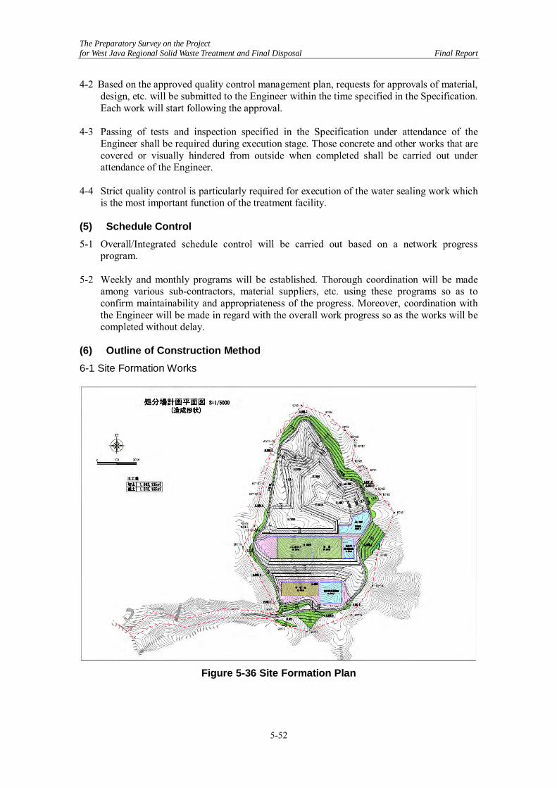
(6) Outline of Construction Method 6-1 Site Formation Works
Figure 5-36 Site Formation Plan

The Preparatory Survey on the Project for West Java Regional Solid Waste Treatment and Final Disposal Final Report
5-53
Execution of earth work will be scheduled in dry seasons as much as possible with considering the characteristics of the soil and rainfall condition in the region. And soil slopes exposed by the earth work should be covered and protected by grass using seed shooting work. The earth work contents mass excavation in the landfill area and transportation of the excavated material to the fill area for the embankment of EL 985 m and EL 1,020 m and transportation of surplus material to the temporary stock area. Equipment for the earth work will be Excavators (Back-hoe) for cutting/loading/shaping slope etc., Dump Trucks for transportation of soil, Bull-dozers for cutting/moving/spreading and compacting soil, Roller for compaction of soil, and others. The earth work equipment will be selected as bigger sized, however it should not be special type/model which will not be obtained in Indonesia. 6-1-1 Work Execution Flow 1. Survey 1) Confirmation of the site premises boundary and clearing area 2) Acquisition of the Engineer's approval 2. Clearing & Grubbing 1) Following the confirmation of site premises boundary, clearing area will be indicated using
tape, etc. The f clearing work will be carried out after confirmation by the Engineer. 2) Clearing and grubbing will be thoroughly and neatly executed so no remaining roots, etc.
shall obstacle the sealing works. 3) The initial clearing will be carefully executed at the area within approx. 2m line from the
boundary so as to avoid sequential falling down of trees due to strong wind or collapse of the slope, etc.
4) Trees, leaves, roots, grasses and other rubbish will be suitably treated based on the instruction of the Engineer.
3. Temporary Works 1) Temporary Drainage
• Temporary drainage will be provided so as not to hinder the upstream water flow for the period between start of the felling work and completion of the main trunk drainage.
• The temporary drainage will be made of pipes and channels using corrugate pipes, etc. to be installed suitably for site conditions maintaining thorough flowing capacity. Changing over of drainage will be made based on earthwork progress.
• Safety device such as screen will be provided on the inflow mouth so as to prevent any person, especially local children, from dropping into the mouth.
• Temporary sedimentation ponds will be provided so as to prevent turbid water from flowing into downstream rivers during rains. Sediment in the ponds will be periodically dredged using small backhoe, etc.
2) Temporary Roads • Design of the temporary roads will be carried out maintaining safety grade of slope to
prevent traffic accidents during the works. Crushed stone will be spread over the surface of the roads to maintain vehicles’ trafficability and prevent slipping accidents during rain.
• Temporary roads will be diverted occasionally based on the progress of the earthwork. Drainage pipe will be installed for ravine area if needed to prevent water ponding at upper stream side.

The Preparatory Survey on the Project for West Java Regional Solid Waste Treatment and Final Disposal Final Report
5-54
3) Other Temporary Facilities • As for other temporary facilities such as temporary office, substations, water supplying
facilities, etc., their structural design and construction method will be established based on careful site investigation and the Engineer's approvals.
• As for temporary safety facilities such as sedimentation ponds, timber made channel, pedestrian walkways, etc., their structure shall be firm from safety viewpoint, derived through consultation with the Engineer, necessary reinforcement works will be provided and thorough maintenance will be provided.
• Thorough safety analysis, necessary facilities will be provided especially for the safety of local residents. Meetings with local residents will be held under the Engineer's consent to explain the works and latent dangers and to let them understand those dangers.
4. Earth Work (Site Formation) 1) Cutting Work
• Total cutting volume of Legok Nangka area treatment facility construction work is approx. 1,960,000 m3 of which 1,190,000 m3 will be used as filling material for the site development works and the rest of the material, i.e. 770,000 m3 will be temporarily stocked at adjacent area (provided by West Java Government within 1km) to be used later as material of covering, small banking, etc.
• Cutting work will be carried out based on the design drawings, using suitable equipment such as backhoe, bulldozer, dump truck, etc. Prior approvals by the Engineer are required for all cutting works in regard with inspection, etc.
• Specific care shall be paid for slope cutting to meet designated grade, while avoiding loosening of ground due to excess excavation.
• Slope and bottom of the treatment area shall be executed carefully avoiding any unevenness and getting rid of any boulders, stones, etc. for the sake of maneuverability of the sealing work.
2) Filling Work • Site investigation of brook/spring area will be carried out prior to the filling work for
the purpose of preventing future land slide/corruption. Suitable sub-drainage will be installed at brook /spring areas to drain water outside the filling zone prior to the filling work.
• For condition of inclined land, bench cutting to be performed to obtain sufficient flat working space for filling equipment prior to the filling work.
• Trial filling will be carried out prior to the filling work for the sake of deciding the equipment to be used, thickness of layer, number of compaction run, etc. through consultation with the Engineer based on test results derived from this trial filling.
• Filling work will be carried out based on the design drawings using suitable equipment such as backhoe, bulldozer, dump truck, compaction equipment, etc. Prior approvals by the Engineer are required for all filling works in regard with inspection, etc.
• Spreading and compaction of material will be executed conforming to the Specification and test results of the trial filling under the supervision of the Engineer. Necessary rectification measures will be taken through consultation with the Engineer in case of encountering soft ground at the filling area, to avoid future deteriorating settlement.
• No area shall be left without compaction at the end of each day. The surface shall be well compacted to prevent water intrusion, which causes muddy condition. Certain grade shall always be kept at the surface of the layer to drain the rain water.

The Preparatory Survey on the Project for West Java Regional Solid Waste Treatment and Final Disposal Final Report
5-55
5. Slope protection Work 1) All slope surfaces that directly touch the waste shall be covered with sealing sheet. Seeding
will be provided for other slopes after compaction and surface treatment. Suitable material and method of seeding for the area will be selected through consultation with the Engineer.
2) Surface flatness will be maintained through mortar spreading, etc. for the cutting slope, where mechanical finishing is not possible.
3) As for filling slope, slope surface will be thoroughly compacted by using slope bucket, etc. and then, surface protection measures will be done.
6-2 Landfill Liner Works 6-2-1 Standard and Specification of the Sealing Liner Work 1) Sealing Sheet Sealing sheet material will be selected from high elastic type products conforming to the standard specified by the “Japan Sealing Work Association”. (See Fig. 5-37: Each standard value for Durability of Sheet is based on 15 years use.)
2) Protection Mat Protection mat material will be selected from unwoven textile products, either short or long fiber one, conforming to the standard specified by the “Japan Sealing Work Association”. (See Fig. 5-38)
3) Protection Soil layer Surplus excavated material will be fundamentally used as covering soil, but any cobbles shall be removed so as not to damage the sealing sheet. Final thickness of the covering soil is set to be greater than 50 cm.

The Preparatory Survey on the Project for West Java Regional Solid Waste Treatment and Final Disposal Final Report
5-56
6-2-2 Composition of the Landfill Sealing Liner

The Preparatory Survey on the Project for West Java Regional Solid Waste Treatment and Final Disposal Final Report
5-57
Figure 5-37 Sealing Sheet
(The Standard specified by “the Japan Sealing Work Association”)

The Preparatory Survey on the Project for West Java Regional Solid Waste Treatment and Final Disposal Final Report
5-58
Figure 5-38 Protection Mat
(The Standard specified by “the Japan Sealing Work Association”) 6-2-3 Work Execution Flow 1. Checking of Treated Surface 1) Treated surface shall be flat without any matter such as stone, stump, etc. that might damage
the sheet. 2) Both bottom and slope surfaces must be treated without any uneven area and thoroughly
compacted. 3) Countermeasures such as sub-drainage shall be provided prior to placing liner so as no slope
collapse or denudation occurs due to spring water. 2. Spreading of Lower Protection Soil Layer 1) Surplus excavated soil without stone, etc. will be hauled from the temporary stock pile and be
spread by bulldozer, etc. and be compacted by roller of 8 ton to 20 ton class. 3. Placing of Protection Mat 1) Prior to execution, request for approval of the material shall be submitted to the Engineer. 2) The required amount of protection mat will be delivered to the site based on the patching
schedule, and placed by laborers and truck crane, etc. 3) Length of joint overlapping shall be conforming to the Specification and manufacturer's
engineering standards. The joint will be made by manual type welding connector. 4) The protection mat above the sealing sheet shall be placed following thorough cleaning of the
sealing sheet.

The Preparatory Survey on the Project for West Java Regional Solid Waste Treatment and Final Disposal Final Report
5-59
4. Placing of Sealing Sheet 1) Prior to execution, request for approval of the material shall be submitted to the Engineer. 2) The required amount of sealing sheet will be delivered to the site based on the patching plan,
and placed by labors and truck crane, etc. 3) Patching plan of the sealing sheet will be prepared with reasonable patterns so as to minimize
site joint welding. Length of joint overlapping shall be conforming to the Specification and manufacturer's engineering standards. Number of overlapped layers shall be limited to three.
4) Extension of the sealing sheet for the upper side of slope will be carried out from the upper side toward down side manually using rope, etc. Specific care shall be paid during this time so as not to damage the sheet by friction or shock. Sheet edge shall be kept clean. Any oil or mud attached to the sheet will be cleared off using waste clothes, etc.
5) Spread sealing sheet will be temporarily fixed by using sand backs, etc. Spreading work will be suspended under strong wind.
6) Joint welding work shall be executed by engineers with thorough experience. Basics of joint welding are as follows: a. Joint work shall be fundamentally carried out by automatic heat welding tool. The welding length shall be conforming to the Specification and manufacturer's engineering standards. b. Daily trial welding will be carried out so as to decide joint conditions such as welding temperature, roller speed, roller weight, etc. c. Patching plan of the sealing sheet will be prepared with reasonable patterns so as to minimize site joint welding. Padding welding will be provided for those area with three layers overlapping so as to reinforce the water tightness.
7) Inspection for the joint portion shall be carried out to check overlapping width, welding width, water tightness, joint strength, etc. Overlapping width and welding width shall be checked for the whole length. Manual shearing and tensile strength tests shall be provided for all joint edges.
8) Inspection of site joint portion's water tightness shall be carried out within a week after joint work at the site. Visual observation and penetration test with inspection bar will be executed for the whole joint length at first, then followed by either negative air pressure or positive air pressure test using case. These inspection must be done after thorough curing of joint portion.
9) Those sheet blocks that passed the inspection will be covered by upper protection mat after confirming that no gravel or foreign material is on the sheet surface.
10) As for treatment of those areas where sheet and other matter such as concrete structure, sub-drainage for seepage water, etc. meet together, the execution method will be prepared beforehand conforming to the Specification, and consultation with the Engineer.
5. Spreading of upper Protection Soil Layer 1) Covering soil, temporarily stocked at adjacent area, will be hauled to the site and manually
placed on the sheet by using wheel barrow, etc. Manual spreading will be executed followed by compaction using tire-roller of 8 ton to 20 ton class. Assistant worker will be deployed with the tire-roller to check that the tire-roller does not damage the sheet during compaction.
2) Careful manual compaction using small vibration roller will be provided within 2 meter of the bottom area from the intersection of bottom and slope.

The Preparatory Survey on the Project for West Java Regional Solid Waste Treatment and Final Disposal Final Report
5-60
6-3 Water Collection and Removal Facilities 6-3-1 Underground Water Collection and Removal Facility
Figure 5-39 Plan of Underground Water Collection and Removal Facility
6-3-1-1 Work Execution Flow 1. Material Approval and Layout Confirmation of Drainage Pipes 1) Request for approval of the material will be submitted to the Engineer prior to the execution. 2) Double setting high density polyethylene perforated pipes with sufficient durability and
strength will be used as pipe materials. Size and thickness will be decided based on hydraulic and structural calculation.
3) Location of drainage trunk lines will be decided based on thorough consideration for ground conditions including spring water which has become apparent after site development. These locations will be approved by the Engineer through consultation.
2. Excavation 1) Excavation will be carried out based on the design drawings. Specific care will be provided
so as not to loosen the ground by excess digging.

The Preparatory Survey on the Project for West Java Regional Solid Waste Treatment and Final Disposal Final Report
5-61
3. Installation of Drainage Pipes and Filter Material 1) As for joint portion, each inserting length shall be checked so a firm joint will be made. 2) Mono size crushed stone, grade 4, will be placed around the drainage pipe as filter material.
No foreign material such as soil, debris, etc. shall be mixed with the filter material. Placing and compaction of the filter material will be carried out equally at both sides of the pipe so as not to cause impact or partial pressure to the pipes.
3) Concrete plate will be placed above the compacted filter material so as to prevent foreign material such as soil or debris going into gaps of the filter material as they may cause sticking of perforated pipes.
4) Caps will be provided to the edge of pipes to prevent soil going into the pipe.

The Preparatory Survey on the Project for West Java Regional Solid Waste Treatment and Final Disposal Final Report
5-62
6-3-2 Surface water Collection and Removal Facility
Figure 5-40 Plan of Surface Water Collection and Removal Facility
Surface Water Collection and Removal

The Preparatory Survey on the Project for West Java Regional Solid Waste Treatment and Final Disposal Final Report
5-63
6-3-2-1 Work Execution Flow 1. Material Approval and Layout Confirmation of Drainage Pipes, Sump pits and Concrete
Channel 1) Request for approval of the material will be submitted to the Engineer prior to the execution. 2) Double setting high density polyethylene pipes with sufficient durability and strength will be
used as pipe materials. Size and thickness will be decided based on hydraulic and structural calculation.
3) Concrete and re-bars to be used for structures shall be conforming to the Specification in regard with quality and strength. They shall be approved by the Engineer prior to usage.
2. Excavation 1) Excavation will be carried out based on the design drawings. Specific care will be provided
so as not to loosen the ground by excess digging. 2) When encountering changes in the ground condition, the incident will be reported to the
Engineer for his consent and instruction. 3. Installation of Drainage Pipes & Sump Pits and Concrete Channel Work 1) Concrete products without any deficiency such as cracks will be installed. Their strength and
dimensions must conform to the Specification. Specified tests such as bending test, etc. shall be implemented. The quality control data shall be approved by the Engineer prior to the usage.
2) Cast in place concrete shall conform to the Specification. The Engineer's inspection and approval must be obtained before casting.
4. Rain Water Reservoir Works 1) Reservoir will be RC retaining wall and impermeable sheet lining on the bottom. 2) For the Reservoir will be constructed on the filling area due to luck of space in the site, the
structure work should be executed after sufficient period for land settlement. 3) Quality control for the Reservoir construction to be carefully executed especially for water –
tightness so as no water leakage will occur. 5. Backfilling 1) Specific care shall be paid so as no damage occurs to the structures during backfilling. As for
concrete channel portion, filling material will be placed equally in both sides of the channel so no unbalanced pressure occurs and the filled material will be thoroughly compacted.
2) The structure shall be inspected by the Engineer prior to covering.

The Preparatory Survey on the Project for West Java Regional Solid Waste Treatment and Final Disposal Final Report
5-64
6-3-3 Leachate Collection and Removal Facility
Figure 5-41 Plan of Leachate Collection and Removal Facility
6-3-3-1 Work execution Flow 1. Material Approval and Layout Confirmation of Drainage Pipes and Sump Pits 1) Request for approval of the material will be submitted to the Engineer prior to the execution. 2) Double setting high density polyethylene perforated pipes with sufficient durability and
strength will be used as pipe materials. Size and thickness will be decided based on hydraulic and structural calculation.
3) Concrete and re-bars to be used for structures shall be conforming to the Specification in regard with quality and strength. They shall be approved by the Engineer prior to usage.
2. Preparation of Base 1) Thorough compaction will be provided for the protection soil underneath the drainage pipes. 2) Unwoven textile will be placed on the top of the protection soil below the pipes to prevent
the ground from damaging due to leaked water. Joint of unwoven textile will be carried out by welding.
3. Installation of Drainage Pipes and Filter Material 1) As for joint portion, each inserting length shall be checked so a firm joint will be made.
Specific care is required for joint of drainage pipes and sump pits.

The Preparatory Survey on the Project for West Java Regional Solid Waste Treatment and Final Disposal Final Report
5-65
2) Mono-size crushed stone will be carefully placed under the drainage pipe. No foreign material such as soil, debris, etc. shall be mixed with this base material.
3) Mono-size cobblestones without any soil or debris will be placed on top and sides of the drainage pipes. Placing shall be carried out so as not to cause any impact or partial pressure to the pipes, i.e. carefully and equally in both sides.
4) Heavy equipment will be banned to run over the drainage pipes. In case of an unavoidable operation, appropriate countermeasures shall be provided and the Engineer's approval shall be obtained.
5) Caps will be provided at the mouth of pipes to prevent the soil going inside the pipes. 4. Sump Pits and Sump Reservoir Works 1) Drainage pipes' penetrating portion of the sump pits shall be executed carefully so as no
leakage will occur. 2) The concrete-made sump pits shall be watertight structures. The water tightness shall be
mainly depending upon the concrete itself and waterproofing material will be used as auxiliary. 48 hours ponding test will be executed so as to confirm water tightness. No backfilling shall be provided until water tightness is confirmed.
3) Sump reservoir will be constructed by placing concrete plate with 15 cm thick on excavated and compacted slopes and 15 cm thick concrete will be cast at the bottom. A layer of lower protection mat, a layer of water sealing sheet and a layer of upper protection mat made of long fibre unwoven textile will be placed underneath the concrete.
5. Backfilling 1) Specific care shall be paid so as no damage occurs to the structures during backfilling. 2) The structure shall be inspected by the Engineer prior to covering. 6-4 Gas Collection and Removal Facility 6-4-1 Work Execution Flow 1. Material Approval and Layout Confirmation of Gas Collecting Pipes 1) Request for approval of the material will be submitted to the Engineer prior to the execution. 2) Drainage pipe will be also used as gas collecting pipe. Double setting high density
polyethylene pipes with sufficient durability and strength will be used as slope gas collecting pipe materials.
2. Preparation of Base 1) Base will be sufficiently compacted to avoid uneven settlement. 3. Installation of Gas Collecting Pipes and Filter Material 1) Vertical pipe will be extended by jointing pipe along with the progress of the waste filling.
Therefore, necessary protection will be provided to the joint portion to avoid damage. 2) Gas collecting pipe on slope shall be firmly fixed so as not to move or detach at joint during
the waste filling work. 3) Necessary device shall be provided so as no closure of pipe occurs due to soil coming in.

The Preparatory Survey on the Project for West Java Regional Solid Waste Treatment and Final Disposal Final Report
5-66
5.4.4 Leachate Treatment (1) Outline of Construction 1. Position Map
Figure 5-42 Planned Layout of Facility
(2) Outline of Facility The following construction & facility would be established.
Table 5-12 Facility Outline Name Outline
Regulation Pond RC Building : 6,000 m3 Depth: 5m Leachate Treatment Facility
RC Building : 2 stories on the ground 27 m × 35.5 m • Treatment Tank • Machinery • Electrical & Instrumental Facility • Administration Office & Other Incidental Facilities
Regulation Pond And Leachate Treatment Facility

The Preparatory Survey on the Project for West Java Regional Solid Waste Treatment and Final Disposal Final Report
5-67
(3) Construction Schedule Outline of total schedule for establishing the facility is as follow.
Figure 5-43 Construction Schedule
The points to be considered and major features about the total schedule are to
• Well consider a scramble & an adjustment in the facility-establishment schedule of the total project and construct with the safety first.
• Apply the facility-establishment schedule of the total project regarding a temporary infrastructure for the construction.
• Start each execution of the leachate treatment from a possible part with establishment a temporary road and progression of the civil engineering-development on the total site.
• Consider an opinion of enterprise engaging a maintenance operation in deciding the detail facilities during the execution.
• Adjust the total scheme with considering to utilize a free depot of materials for civil engineering of the site office etc & a temporary office space about constructing the regulation pond.
• Plan and construct both the structure of treatment facility and the tank-construction inseparably as a unit
• Consider the operation-maintenance regarding machinery installation & instrumentation, examine and adopt a commodity procured easily in Indonesia
• Consider a traffic line or space for maintenance in installation of machinery. • Consider an opinion of enterprise engaging a maintenance operation about the
administration office & other Incidental Facilities • Consider a preventive maintenance or long operation life of LCC & machinery, procure
and keep enough spare parts in the facility-establishment process. (4) System of Execution and Organization System of Execution & Organization is the following figure.

The Preparatory Survey on the Project for West Java Regional Solid Waste Treatment and Final Disposal Final Report
5-68
Figure 5-44 System of Execution and Organization
System of Execution & Organization is the following figure.
• Have close communication including a report, a contact, and a consultation among each stakeholder such as the West-Java State Government, business entities, SPC, and EPC etc, and progress the uninterrupted facility-establishment.
• Establish the chain of command and improve a systematic response capability with a clarification of a responsibility, a role and a charged range
(5) Safety Control Safety is the priority matter in the construction. Planning for action should be well recognized before the construction, risk prediction & safety protection should be well considered, and well organized safety measure should be performed. In addition, Patrols & checks, protections for accident would be executed with large opportunities of “awareness”, then, it would be consistent to yield no-safety conditions. Main items for the safety control are as follow.
Table 5-13 Items Safety Control Name Detail
Daily
Safety Morning Meeting Announcement of Safety Instructions & Notification Matters KY-KT Meeting Re-confirmation of Risk Prediction (KY), Risk Measure (KT), Safety
Inspection, and Operation Procedure Machinery Inspection before Use
Safety Inspection before Use
Command & Supervision in Operation
Detection of No-Safety Condition & No-Safety Action and Improvement Measure
Safety Process Meeting Announcement & Settlement for Operation of the Next Day and Safety Instructions
5S Arrangement (Seiri), Good Order (Seiton), Cleaning (Seisou), Clean Condition (Seiketsu), Good Manner (Shitsuke)
Safety Confirmation in the End of Operation
Re-confirmation of Scatter & Flames etc
Weekly
Weekly Meeting Result of Safety Patrol and Progress of Operation Schedule Weekly Self-Inspection Inspection of Machinery, Electricity and Temporary Installation Weekly Clean-up 3S of Office & Workshop etc: Arrangement (Seiri), Good Order
(Seiton), Cleaning (Seisou)
Monthly
Safety & Health Committee Reflection of Monthly Safety & Health Objective Accident Prevention Council Reflection of Monthly Safety or Expansion of Case Study: Incident Monthly Meeting Result of Safety Patrol and Progress of Operation Schedule Safety Workshop Meeting Education for Safety & Health and Announcement of Notification
Matters

The Preparatory Survey on the Project for West Java Regional Solid Waste Treatment and Final Disposal Final Report
5-69
(6) Quality Management Main items for the safety control are as follow.
• Obtain agreement about materials (for civil engineering) or a construction technique from a ordering before the execution based on the detailed design.
• Carry out inspections such as an acceptance inspection and number inspection etc under an attendance of ordering on carrying in the site regarding materials (for civil engineering).
• Inspect and confirm the condition before the next process under an attendance of ordering as a rule in each process of execution, and carry out a complete inspection on a completion of execution.
• Carry out inspections such as a filling-water test or a pressure test etc for testing a leakage of a tank & a plumbing or not, and incorporate those tests beforehand in case of taking certain time for testing.
• Carry out individual and whole inspections such as a performance test, a quality test, an each operation test: a rated value and a full value, and an emergency stop operation test etc for showing specified ability and function of the total system or not until a trial operation previous to a complete handing over.
Figure 5-45 Multiple Monitoring
• Carry out a multiple monitoring among a contractor, an administrator or administration
division of each business entity, a supervisor, SPC, and PM enterprise as well as a monitoring of ordering.
(7) Control Process Consideration & features about the process control are to:
• Hold a related council for related business entities and stakeholders, if necessary, and progress the uninterrupted construction work with sharing information or controversial issues of the civil engineering process condition etc.
• Realize a responsibility and a role for each stakeholder with creating a mile-stone, clarify a important arrival point in the process, and recognizing the target in the process of each construction-stakeholder, progress improvement of awareness, and reach the more smooth progress management than before.
• Make an integrated progress schedule with examining drawings and specifications and securing an appropriate construction term, and keep it with early preparation of a working drawing and detailed discussions; in addition, progress the uninterrupted constructive promotion and prevent a rework by making a construction planning & an operation procedure previously with agreement of ordering, and well-informing persons & technicians in charge of operation.

The Preparatory Survey on the Project for West Java Regional Solid Waste Treatment and Final Disposal Final Report
5-70
Figure 5-46 Flow of Control Process
(8) Emergency Response System Supposed emergencies such as accidents, natural disasters, and incidents would be investigated, and formalized its response corresponding to each case and significance. In the emergency, as a rule, under a command of leader, information and the chain of command are integrated and prompt and appropriate response would be carried out with closed communications with ordering and stakeholder.
Figure 5-47 Emergency Response System

The Preparatory Survey on the Project for West Java Regional Solid Waste Treatment and Final Disposal Final Report
5-71
Supposed Contacts: • Ordering, SPC/EPC, Disaster Prevention Department of Regional Administration,
Police Station, Fire Station, Related Constructor, Cooperative Business Entity, Partners, Infrastructure Business Entity, Other Stakeholder
Supposed Main Factors of Emergency:
• Natural Disasters - Heavy Rain, Gust, Tornado, Storm, Thunder, Earthquake, Landslide etc
• Accidents - Traffic Accidents, Conflagration, Mechanical Abnormality, Electric Shock,
Leakage, Others • Incidents
- Injury, Theft, Violation, Riot, Terrorism, Intimidation, Others (9) Outline of Construction Technique
• Regulation Pond - Based on the design, digging & unevenness adjustment etc by the civil engineering
work would be carried out. In addition, the outer wall and batholith of pond would be constructed with a reinforced‐concrete construction to protect leakage of leachate.
• Leachate Treatment Facility
- Facility Building including the tank would be constructed with 2 stories above ground & a reinforced‐concrete construction
- The tank of lechate treatment facility would be constructed with a liquid‐applied membrane waterproofing, and a filling-water test should be carried out after finishing the construction.
- Machinery would be procured easily in Indonesia with considering the maintenance. All machineries should be accepted with specifications & drawings before manufacturing, and its quality test with a manufacture responsibility should be carried out after the accomplishment of construction. Inspections, moreover, should be carried out on its emplacement and confirmation & inspections, operation tests, for showing specified ability and function or not should be carried out on its trial run.
- Plumbing would be procured easily in Indonesia with its prior approval about employed materials or construction techniques. Number inspections & acceptances should be carried out on its emplacement; moreover, pressure tests or filling-water test should be carried out to confirm leakage from the plumbing after the accomplishment of construction.
- Electrical & Instrumental Facilities would be procured easily in Indonesia with its prior approval about employed materials or construction techniques. Number inspections & acceptances should be carried out on its emplacement; moreover, inspections should be carried out to confirm its quality & operation after the accomplishment of construction.
5.4.5 Common Area Construction – External Work (Roads, Drainage, and
Vehicular Parking) (1) Introduction This Method Statement describes the work procedures in road works, drainage works and vehicular parking works. The major items and construction schedule as shown below.

The Preparatory Survey on the Project for West Java Regional Solid Waste Treatment and Final Disposal Final Report
5-72
(2) Major Items 1. U-shape drainage work. 2. Man-hole work. 3. Asphalt work
• Sub-grade work • Lower Sub-base course • Upper Sub-base course • Prime and Tact Coat work. • Asphalt pavement work • Installation of road furniture and guardrail work • Road makings work
(3) Program
A COMMON AREA 1
1 Mobilisation
2 Setting Out Work
3 U Drain
Manhole
Precast Yard Preparation
Pre cast of Manhole
Installation of Manhole
Asphalt Road
Preparation Work
Excavation
6.0m Width Road
6.0 to 10.0m Width Road
10.om Width Road
B COMMON AREA 2
Gravel Pavement -Base Preparation
Gravel Pavement Laying
Asphalt Road
4
5
S No MONTHSDESCRIPTION7 8 9 10 111 2 3 4 5 6
Figure 5-48 Program for Common Area Construction
5.5 Operation and Management 5.5.1 Operational Structure
• Table 5-14 shows an O&M System. 457 workers including the director manage operating and administration
• In the operating sector a manager and workers are assigned every plants, and in the administration sector a manager is assigned and workers are assigned every assignment segments

The Preparatory Survey on the Project for West Java Regional Solid Waste Treatment and Final Disposal Final Report
5-73
Table 5-14 Operational Management of Plants System
Position Subtotal
Director 1
Sorting Compost LandfillLeachetetreatment
Acceptance&
measurementAccounting
Manager 1 1 1 1 5
Operationgadministrationmanager
4 - - - - - 4
Plantequipmentoperater
16 - - - - - 16
Heavyequipmentoperater
30 40 4 - - - 74
QC engineer - - - - - - 0
Maintenanceworker
2 2 1 2 - - 7
Worker - 4 3 - 9 3 19
Worker(Hand sorting)
340 10 - - - - 350
Total 476
1
Director
5.5.2 Sorting (1) Abstract of Operation
1. The waste should be received in 16hrs (8:00~24:00). 2. The waste delivered in non-operating time should be pooled in receiving yard. 3. Time schedule of operation
08:00–24:00 operation 20:00–24:00 maintenance
4. The workers shift: The others 08:00–17:00 day shift working 16:00–24:00 late shift working
The worker number and work time considered for shift work are shown in Table 5-15.

The Preparatory Survey on the Project for West Java Regional Solid Waste Treatment and Final Disposal Final Report
5-74
Table 5-15 Work Item and Wok Times and Numbers
Work item Working
Hours (hrs/Day)
Day shift working
8:00–17:00 Figure
Late shift working
16:00–24:00 Figure
Total
Surveyor for receiving pit(worker) 16 4 4 8 Operators for Heavy Equipments at receiving 16 3 3 6 Operators for plant equipment 16 5 5 10 Manual Labors for sorting (worker) 16 144 144 288 Bag Packing for plastic material(worker) 16 24 24 48 Operators for Heavy Equipments at storage 8 3 3 6 Maintenance worker 8 2 2 Operating Administration manager 12 3 2 5 Site manager 8 1 1 Total 189 185 374 (2) Abstract of Maintenance To avoid the fatal troubles, the appropriate daily maintenance and periodical maintenance (inspection) must be required. For above affairs, all personnel have to understand every method of the operation and maintenance, completely.
Table 5-16 Daily Operation & Maintenance (Examples) DAILY MAINTENANCE REQUIREMENT
• To grasp equipment operation and adjustment for fluid volume, aeration, to medicine addition amount
• To confirm for the situation of operation with equipments (current amount, vibration, eccentric sound, etc)
• To confirm and make a record of indicated amount by measure equipment
• Replenish consumed medicine and filling by equipments
• To check the leak from tank, pipe and other equipments
• The condition with tear for equipments, damage of belt, oil leak, and necessary repair for above
• To issue the daily bulletin
• To understand the superannuation through daily maintenance, and make a plan to replacement.
• To replace grease and oil (Lubrication) • Calibration, cleaning and replace tired parts
for the instrument • Overhaul for utility equipments (if necessary,
order to specialize company) • Replace tired parts and maintenance for
electrical control circuit of instruments for measurement equipment of the power sauce devices (if necessary, order to specialize company)
• To make a record for the result of periodical maintenance
(3) Recommendable System and Organization for Operation and Maintenance
(Example) Suitable system/organization for proper operation and maintenance should be established according to the condition of detail design and conditions of construction. For reference, we show recommendable system/organization as below Table 5-17.

The Preparatory Survey on the Project for West Java Regional Solid Waste Treatment and Final Disposal Final Report
5-75
Table 5-17 Recommendable System and Organization for Operation and Maintenance (Example)
Title Job Descriptions Demanded Skills Surveyor for receiving pit(worker)
• To survey for the acceptance • To eliminate foreign material
-
Operators for Heavy Equipments at receiving
• To transfer with heavy equipments from receiving pit to receiving hopper
• License of Heavy Equipment
Operators for plant equipment
• Daily Maintenance & Periodical Maintenance
• Adjustment for operation regarding to the order by the manager
• General knowledge about operation and maintenance for the plant and relating equipments
• General knowledge about measurement and analysis
Manual Labors for sorting (worker)
• Manual Sorting at Conveyer Line • Maintenance after daily
operation
-
Bag Packing for plastic material(worker)
• Sorting and Packing by eliminated plastic material into bags for both recycling and elimination
-
Operators for Heavy Equipments at storage
• Transferring and Loading to carriers (trucks) from stock-yard with a forklift
• License of forklift and Crane
Maintenance worker • Maintenance of equipments and instruments
• General knowledge about equipments and instruments
• Knowledge available for simplified maintenance
Operating Administration manager
• Central Command • (General Survey) • Unified Operation • (Operation& Maintenance) • Adjustment for the operation
with reference to Operation Index, and appropriate command to every personnel
• Trouble Shorting
• Over-all knowledge for the operation and control of the plant
Site manager • Possibility for over-all • Same skill of the Central Commander
• Business Skill • Crisis management capability
5.5.3 Compost (1) Operation
1. The organic waste sorted is loaded on dump trucks by a wheel loader, transported to a windrow hall and unloaded at spot as instructed.
2. The waste is piled up trapezoid in cross section as windrow by a wheel loader. 3. The windrows are turned from time to time by a windrow turner. 4. The windrow stands for 20 days for the natural process of decomposition of the
organic matter. Then the waste is screened, loaded by a wheel loader on dump trucks employed by WJPG, and taken out.
In the operation 7 wheel loaders, 10 dump trucks, 1 windrow turner, and 1 screen are used 12 hours a day.

The Preparatory Survey on the Project for West Java Regional Solid Waste Treatment and Final Disposal Final Report
5-76
(2) Organization The operation is done by
1. 1 Manager; 2. 40 Equipment Operators in 2 shifts; 3. 2 QC Engineers in 2 shifts; 4. 4 Mechanics in 2 shifts; and 5. 10 Common Workers in 2 shifts.
5.5.4 Sanitary Landfill (1) Landfill System
• The basic landfill system is “cell system”. Cell system is a waste disposal system that the day’s waste is loaded to the dipping bed by bulldozer and other heavy machines and then they are masked by cover soils (0.15 m) superior and side surface day after day (daily cover).
Figure 5-49 Cell System
• Each cell is separated by daily cover. Thus it is very effective for the prevention of
backfire, spreading fire, reek of rot drift hazard and controlling harmful insects • Each waste layer (thickness: 2.15 m including daily cover 0.15 m) is separated by
intermediate cover soil layer (thickness: 0.35 m). (2) Landfill Works
• Landfill works is go through the following steps: 1) Waste is unloaded from the waste collecting truck. 2) Waste is mixed and its surface is leveled off. Then waste is flatted. 3) The daily cover is given.
• Workers are staffed in the repository. When waste-collecting truck is arrived, they lead it, place the acceptance check of the waste at the waste inspection station whether unsuitable thing is not included.
• Landfill procedure go through the following steps: 1) Lead the waste collecting truck. 2) Place the acceptance check of the waste at the waste inspection station 3) Mix the waste, level off its surface and compactify it. 4) Carry the cover soil from lay-down and mask it.
• Workers take measures for the structure object and the impermeable liner. • Vertical gas collection pipes etc. are set up to maintain the semiaerobic landfill structure
with vertical gas collection pipes and leachate collection lines.
Daily cover
Cell of day’s waste

The Preparatory Survey on the Project for West Java Regional Solid Waste Treatment and Final Disposal Final Report
5-77
(3) Cover Soils Works • Figure5-50 shows slope of landfill. Waste is covered with the small dam, intermediate
cover soil and the final cover soil. Waste is masked by cover soil the same day. • The landfill slope of the dam is constructed in the progress of landfill. In addition,
seepage control work is undertaken on the inside of the dam at the same time and then a sheet fixing and a drain ditch are also undertaken.
• The effects of soil covers, countermeasure on environment conservation, are prevention of dispersal and washout of waste, exuding strong odors and vermination
Intermediate cover: Thickness is 50 cm in each 2.0 m of waste layer. Daily cover: Thickness is 0.15 m. Final cover: Thickness is 0.65 m (include cover soil t= 0.5 m and humus and grassing t = 0.15 m) for the re-vegetation, creation of the forest, based on the land utilization plan after completion of landfill. Cover material: Excess soil (cut-embankment balance) from onsite.
1:2.0
Waste layer t=2.15 m5.0m
2.5m
1.5m
12.0 m
1:2.5
2.0m
2.5m
2.65m5.15m
Seepage control work(Impermeable liner)
Drain ditch
Final cover t=0.65 m
Waste t=2.0m
Intermediate cover t=0.35 m
Retaining DikeIntermediate cove t=0.35m
Daily cover t=0.15 m
Humus and Grassing t=0.15 m
1:2.0
Waste layer t=2.15 m5.0m
2.5m
1.5m
12.0 m
1:2.5
2.0m
2.5m
2.65m5.15m
Seepage control work(Impermeable liner)
Drain ditch
Final cover t=0.65 m
Waste t=2.0m
Intermediate cover t=0.35 m
Retaining DikeIntermediate cove t=0.35m
Daily cover t=0.15 m
Humus and Grassing t=0.15 m
Figure 5-50 Slope of Landfill
(4) Landfill strategy
• Waste is land-filled from the downstream side in consideration of dropping into naturally draining of rainwater, etc. for safety and efficiency. In addition, the dam is constructed in the progress of landfill and waste is land-filled on a step-by-step basis
• The doneness, the land sinking and the rest landfill capacity of the landfill site are kept tabs on for management to operate properly.
(5) Landfill Equipments
• Table 5-18 shows the functions and number of landfill equipments in consideration of the landfill system, waste production and land-filled solid waste, etc.
• The scheme is premised on the case: 10 t trucks of 25/day and waste transaction volume of 339 m3/day.

The Preparatory Survey on the Project for West Java Regional Solid Waste Treatment and Final Disposal Final Report
5-78
Table 5-18 Landfill Equipments Landfill equipments Number/day Remarks
Backhoe (0.7 m3) 2 Covering soil Checking
Bulldozer (21 t) 1 Surface compaction Flattening out
Landfill compactor (25 t) 1 Surface compaction Dump truck (10 t) 3 Transportation of waste from intermediate treatments
landfill site (6) Personnel Distribution
• The scheme is premised on the case: 10 t trucks of 25/day and waste transaction volume of 339 m3/day.
• Hours of work premised 8:00–17:00 with a group. • Simulate to be procured from local people in Indonesia. • In addition, working out of regular monitoring by O&M companies about once every
six months is proposed to be implemented.
Table 5-19 Staff of O&M of Landfill System (Field Site) Position Principal works
Manager (1)
・ Total management of landfill ・ Liaison coordination and intercommunication with other
plants. Heavy equipment operator (4)
・ Landfill and cover soil works.
Plant and heavy equipments controller (1)
・ Maintenance of plants and heavy equipments. ・ Checking and maintenance of access aisles. ・ Regular checking of the dam and the slope.
Landfill worker (3)
・ Leading waste collecting truck, checking waste and leading of unloading.
・ Management of collected waste (7) Design for Human Resource Development Design for human resources development are worked out with the aim of an introduction of skill related to operation of plants and establishing of skill, and carried out with executives and middle-level executives with the aim of training of leadership role.
• Skill development by training and dispatch of experts (especially seepage control work and handling skill of liner sheet).
• Trainings of business management of landfill are worked out with executives and middle-level executives.
(8) Safety and Health Design
• Safety and health designs are drawn up annually with the aim of safety of worker and working environment and familiarized to worker.
• Safety and health designs consist mainly of as follows: 1. Set outlines. 2. Forwarding of efforts to be safety is shown to workers with the aim of
prevention of accidents and disasters.

The Preparatory Survey on the Project for West Java Regional Solid Waste Treatment and Final Disposal Final Report
5-79
3. Set objectives 4. Objectives based on outlines, assessments of safety and health designs in the
past and assumed risks are set with concrete numerical values. 5. Select important issues
Specific means for achieving the goal are, enhancement safety management system, introductions of risk assessment, providing safety and health trainings, improvements of machines and equipments.
• Degree of goal achievement made a valuation at the end of the year is reflected programs for the coming year.
(9) Safety Training for Workers Safety trainings are regularly provided with the aim of betterments of safety awareness of workers.
• Day after day at morning meeting: Confirm works and identify assumed risks. • Twice/year: Lecture class for heavy equipments and dump trucks drivers. • Once/year: Compulsory safety trainings.
(10) Programs of Utilization of a Vacant Lot Use of a vacant lot of the post-landfill works includes forest and grass field reduction, parks, a factory complex and residential estate. Forest and glass field reductions are brought forward in case of this project in mind determinate configuration of landfill and ambient surroundings. Depending on the case, determine the site of a vacant lot to reflect the views of stakeholders. Mainly control points of a vacant lot of landfill are brought forward as follows: 1. Volume-loss management of leachate: Expeditious draining away of rain water to outside
of landfill and securing of aerobic condition in landfill. 2. Landfill gas generation management: Release gas from ground level by gas collection pipes.
Manage end of gas collection pipes in fear of close in to disinterested parties. 3. Landfill settlement management: Manage landfill settlement to prevent deep differential
settlement insofar as leaving rainwater drainage designs untouched. 4. Circumjacent groundwater management: Manage circumjacent groundwater at fixed
intervals and check presence or absence of leaking of leachate to circumjacent groundwater. 5. Degradation of land-filled solid waste and stabilization aspect management : Determine (1)
compositions, (2) ignition loss, (3) moisture, (4) water quality of puddles in waste layer, (5) gas aspect, (6) temperature, (7) others with regularity in order to determine degradation of land-filled solid waste and stabilization aspect.
(11) Costs of O&M of landfill site Table 5-20 shows costs of O&M of Landfill.

The Preparatory Survey on the Project for West Java Regional Solid Waste Treatment and Final Disposal Final Report
5-80
Table 5-20 Costs of O&M of Landfill Expense item Cost Remarks column
Labor cost 51,480 USD/yr Calculated based on wage of TPST BANTARGEBANG. (1) Manager: 1 person × 1,650 USD/month × 12 month (2) Heavy Equipment Operator: 4 person × 330 USD/
month × 12 month (3) Maintenance Worker: 1 person × 30 USD/month × 12
month (4) Worker: 3 person × 330 USD/month × 12 month
Utility Electricity 0 USD/yr ・ N/A
Fuel (Heavy equipment)
275,440 USD/yr ・ Heavy equipment’s fuel is diesel oil. ・ Piece rate of diesel oil is 11,000Rp/L ・ Amount of fuel use(Equipments ①–③ is 8 hours/day,
300 days/year in production. Equipment ④ is for the transfer in plants. Thus they work 8 hours/day, 300 days/year in produc
Water 0 USD/yr ・ During the dry season, watering may have to keep back dispersal of waste in O&M of landfill.
・ Using well water since there are no clean water plants (initial cost of 100 m well (earthwork and pomp) is ¥200,000).
Medical agent 0 USD/yr ・ N/A Maintenance and repair cost 416,585 USD/yr ・ The degradation of the liner sheet and the fracture by
heavy equipment miss operation. ・ The breach of groundwater collecting lines, leachate
collection lines, rain water collection lines by subsidence, and the clogging and so on.
・ The falling of slopes by raining ・ Flood to out-of-bounds and damage of sediment
discharge. ・ Mowing cost in slopes.
Others Cover soil purchase
0 USD/yr ・ Use excess soil (cut-embankment balance) from insite.
Leveling of a dam
405,729 USD/yr ・ Buying cost and transport cost of soil. ・ Construction cost of the dam. ・ Laying cost of impermeable liners (Liners laid slope
inside the dam). ・ Laying cost of vertical gas collection pipes(Lay
vertical gas collection pipes (φ600 mm) in one place/2,000 m2)
・ Others (Such as sheet protection layer) Accumulated fund of maintenance (Closing reserve)
0 USD/yr ・ N/A
(12) Monitoring Design Landfill monitoring are provided based on “Government Regulations about Management of Water Quality and Control over Water Pollution” in the Republic of Indonesia due to important factors to evaluate landfill stabilization(The details of A are described in 7.2.1.). Monitoring items and frequencies of groundwater and final effluent is as follows.

The Preparatory Survey on the Project for West Java Regional Solid Waste Treatment and Final Disposal Final Report
5-81
Table 5-21 Items of Monitoring of Groundwater
Preinitiationof landfill
One ormore times
Once a month Once a year Once a month Once a year
Physics
Temperature ○ ○ ○ ○ ○
TDS ○ ○ ○
TSS ○ ○ ○
pH ○ ○ ○ ○ ○
BOD ○ ○ ○
COD ○ ○ ○
DO ○ ○ ○
PO43− as P ○ ○ ○
NO3 as N ○ ○ ○
NH3-N ○ ○ ○
As ○ ○ ○
Co ○ ○ ○
Ba ○ ○ ○
B ○ ○ ○
Se ○ ○ ○
Cd ○ ○ ○
Cr(VI) ○ ○ ○
Cu ○ ○ ○
Fe ○ ○ ○
Pb ○ ○ ○
Mn ○ ○ ○
Hg ○ ○ ○
Zn ○ ○ ○
Chloride ○ ○ ○
Cyanide ○ ○ ○
Fluoride ○ ○ ○
NO2-N as N ○ ○ ○
NO3-N ○ ○ ○
Chlorine free ○ ○ ○
H2S ○ ○ ○
InorganicChemistry
Items
Monitoring frequency
Initiation ~ Completion Completion ~ Abolition

The Preparatory Survey on the Project for West Java Regional Solid Waste Treatment and Final Disposal Final Report
5-82
Table 5-22 Items of Monitoring of Final Effluent
Preinitiationof landfill
One ormore times
Once a month Once a year Once a month Once a year
Physics
Temperature ○ ○ ○ ○ ○
TDS ○ ○ ○
TSS ○ ○ ○
pH ○ ○ ○ ○ ○
Fe ○ ○ ○
Mn ○ ○ ○
Ba ○ ○ ○
Cu ○ ○ ○
Zn ○ ○ ○
Cr(VI) ○ ○ ○
Cr ○ ○ ○
Cd ○ ○ ○
Hg ○ ○ ○
Pb ○ ○ ○
Sn ○ ○ ○
As ○ ○ ○
Se ○ ○ ○
Ni ○ ○ ○
Co ○ ○ ○
CN ○ ○ ○
H2S ○ ○ ○
F ○ ○ ○
Cl2 ○ ○ ○
NH3-N ○ ○ ○
NO3-N ○ ○ ○
NO2-N ○ ○ ○
BOD ○ ○ ○
COD ○ ○ ○
MBAS ○ ○ ○
Phenol ○ ○ ○
Vegetable Oil ○ ○ ○
Mineral Oil ○ ○ ○
Inorganic Chemistry
Items
Monitoring frequency
Initiation ~ Completion Completion ~ Abolition
• Workers monitor condition of stabilization of waste to check landfill gas quality and quantity and ground temperature.
• Examination is worked out in 4 places, which supposed to large gas yield, and conduct a review of monitoring positions and position's numbers as results of yielded gas.

The Preparatory Survey on the Project for West Java Regional Solid Waste Treatment and Final Disposal Final Report
5-83
Table 5-23 Items Monitoring of Landfill Gas and Underground Temperature Checking spot Landfill gas treatment plant (vertical gas collection pipe) Number of Checking points 4 points Number of times Twice/year (summertime, wintertime)
Items of checking
Landfill gas quantity: Measurement of gas flow rate Landfill gas composition: methane (CH4), carbon monoxide (CO), carbon dioxide (CO2), hydrogen sulfide (H2S), ammonia (NH4), oxygen (O2) and azote (N2) Underground temperature in landfill:Measurement of temperature each 1 m deep.
• Bad odor is monitored in FDS boundary.
Table 5-24 Items of Monitoring of Odor Checking spot Ground boundary of east and west side Number of times Twice/year (summertime, wintertime)
Items of checking Odor index (Desired value 12) (corresponding to odor intensity 3.0)
5.5.5 Leachate Facility (1) Outline of Daily Operation i) Staffing and Working hours
Table 5-25 Leachate Facility Staffing and Working Hours Type of Occupation Working Hours Duties # of staff Operation Control Manager
9:00-17:00 (full time, 5 days a week)
• Total Operation Management 1
Maintenance Engineer
9:00-17:00 (full time, 5 days a week)
• Facility Operation • Daily Inspection
2
ii) Duties
Table 5-26 Leachate Facility Duties Type of Work Duties Total Operation Control
Management of Leachate Treatment Facilities (Planning, Operation Leading, Water Quality Control, Emergency Control , Budget Control, Purchasing Control, Safety Management & Sanitation Control, General Affairs)
Facility Operation & Daily Inspections
Operation Control, Facilities Inspections, Light-Maintenance, Chemicals Supply, Water Quality Inspections, Leachate Circulation Work, Unloading Disposal of Dehydrated Cake Work

The Preparatory Survey on the Project for West Java Regional Solid Waste Treatment and Final Disposal Final Report
5-84
(2) Maintenance Table 5-27 Leachate Facility Maintenance
Personnel System Duties Frequency & Term 2 (holding other duties: inspections for other facilities)
Periodical Inspection for Pumps, Blower, Hydroextractor and Mixer
Once per year
Exchange of activated carbon for Activated Carbon Absorption Tower
Once or twice per month
Exchange of Filtration Sand for Sand Filtration Tower
Once per every two years
Periodical Analysis for Raw Water & Discharged water
Once per month
(3) Planning for Monitoring
• Table 5-22 refers monitoring once per month and once per year. • Daily monitoring required the water-purify control would adopt measuring instruments
such as the pH meter, the dissolved oxygen analyzer, and the ORP meter; moreover, Simplified Water Inspection Products, using color former such as the “pack-test” etc, would be practiced if necessary.
5.5.6 Common Area (1) Work Contents
• Workers accept collected waste, check waste by watching, measure waste production and manage data.
• Workers manage cash flows and supports government.
(2) Personnel Distribution Table 5-28 Staff of O&M of Common Area
Position Principal works Director (1 person)
• Management of the entire project.
Manager (1 person)
• Total management of acceptance and measurement • Liaison coordination and intercommunication with other plants.
Back-coated worker (3 persons/shift × 3 shifts)
• Management of acceptance of waste by visual check. • Management of expense sheet • Batching by weight and data management
black-coated worker (3 persons)
• Finance and accounting (management of cash flows) • Accommodation and works, general affairs, labor management. • Clerk • Supporting government such as reports.

The Preparatory Survey on the Project for West Java Regional Solid Waste Treatment and Final Disposal Final Report
5-85
(3) O&M Cost of Common Area Table 5-29 O&M Cost of Common Area
Expense item
Cost Remarks column
Labor cost 87,100 USD/ yr ・ Calculated based on wage of TPST BANTARGEBANG.
・ (1) Director: 1person × 2610 USD /month × 12 month
・ (2) Manager: 1 person × 1,650 USD / month × 12 month
・ (3) Worker: 12 person × 250 USD / month × 12 month
Utility Electricity 960 USD/ yr ・ Base cost (connection fees) : about 20,000 Rp/kVA・month
・ Specific cost: about 200 Rp/kwh Fuel (heavy equipment)
0 USD/ yr
Water 357,804 USD/ yr ・ Buy the Aqua as a drinking water. ・ Research market rate of buying cost.
Chemicals 0 USD/ yr ・ N/A Maintenance and repair cost
0 USD/ yr
5.6 Cost Summary 5.6.1 Facility and Equipment Costs The Facility Initial Construction Costs and Equipment Costs are summarized as follows.
Table 5-30 Facility Construction and Equipment Costs Item Cost Currency Public/Private
Intermediate Treatment Facility
Sorting 17,320,091 USD SPC Compost 7,634,673 USD SPC
Final Disposal Site Landfill 59,512,176 USD Public Leachate Treatment 15,443,000 USD Public Common Area 5,827,566 USD Public
Final Disposal Site Machinery
Landfill Heavy Equipment 1,516,484 USD SPC
Common Area Heavy Equipment 60,975 USD SPC
Capital Costs Total 107,314,965 USD 5.6.2 Operation and Maintenance Costs The annual operation and maintenance costs are shown below.

The Preparatory Survey on the Project for West Java Regional Solid Waste Treatment and Final Disposal Final Report
5-86
Table 5-31 Annual Operation and Maintenance Costs Item Cost Currency Public/Private
Intermediate Treatment Facility
Sorting 1,610,225 USD/yr SPC Compost 863,843 USD/yr SPC
Final Disposal Site
Landfill O&M 1,149,234 USD/yr SPC Leachate Treatment O&M 675,520 USD/yr SPC
Common Area O&M 93,480 USD/yr SPC Insurance 231,805 USD/yr SPC O&M Annual Costs Total 4,624,108 USD/yr
The below items for the Financial Analysis are discussed in Chapter 12.
1. Assumption for Inflation Rate 2. Assumption for Depreciation 3. Assumption for Interest Rate 4. Assumption for Foreign and Local Currency Costs 5. Considerations for Interest Fluctuation Risk 6. Considerations for Foreign Exchange Risk 7. Assumptions for Calculating Insurance Costs (Refer to Chapter 10) 8. Calculation of Project IRR, Equity IRR, DSCR 9. Calculation of FIRR

The Preparatory Survey on the Project for W
est Java Regional Solid Waste Treatm
ent and Final Disposal
Final Report
5-87
Table 5-32 O&M Costs
Director Manager OperatingAdministration manager
Plantequipmentoperater
Heavyequipmentoperater
QC engineer Maintenanceworker
Worker Worker(Hand
sorting)
●Generalization(Communalarea)
・8h/day・250day/year
1(31,320
USD/yr)●Finance andaccounting(Communalarea)
・8h/day・250day/year
3(3,000
USD/yr)
●Acceptanceandmeasurement(Communal
1,000t/day ・24h/day・8h/shift×3shift・360day/year
9(3,000
USD/yr)
・Backhoe(compactsize)×1
・Electricity: 960USD/yr・Water: 5,400USD/yr
●Sorting 1,000t/day ・24h/day・8h/shift×3shift・360day/year
1(26,400
USD/yr)
4(19,800
USD/yr)¥
16(3,960
USD/yr)
30(3,960
USD/yr)
2(3,960
USD/yr)
340(2,400
USD/yr)
・Electricity: 43,787USD/yr・Water:-・Fuel: 203,000USD/yr・Chemicals: 30,066
49,451 USD/yr ・Repair cost ofaccess road:14,000 USD/yr・Crushing machine: 158,242 USD/yr
●Compost 729t/day ・12h/day・360day/year
1(26,400
USD/yr)
40(2,640
USD/yr)
2(2,640
USD/yr)
4(2,640
USD/yr)
10(1,320
USD/yr)
・Wheel loader×7・Dump truck×10・Turner×1・Screen×1
・Electricity:-・Water:-・Fuel:408,039USD/yr・Chemicals:-
298,005 USD/yr
●Landfill 339m3/day ・8h/day・360day/year
1(19,800
USD/yr)
4(3,960
USD/yr)
1(3,960
USD/yr)
3(3,960
USD/yr)
・Backhoe(0.7㎥)×2・Bulldozer(21t)×1・Landfill compactor(25t)×1・Dump truck(10t)×3
・Electricity:-・Water:-・Fuel: 275,440USD/yr・Chemicals:-
416,585 USD/yr ・Leveling of a dametc.: 405,729USD/yr・Cover soilpurchase:-
●Leachetetreatment
・7h/day・6day/week(313day/year)
1(19,800
USD/yr)
2(3,960
USD/yr)
・Heavyequipments(scoop upa dehydratedcake(85%, 3.2t/day)from concrete floor,load it onto a truck,landfill)
・Electricity:19,000USD/yr・Water:-・Fuel:-・Chemicals:520,000USD/yr
80,000 USD/yr ・Water monitoringcost(once/month)(raw water and finaleffluent): 28,800USD/yr
OthersRepair costUtilityPersonnel distribution Heavy equipmentsAdministrationsector
Transactionwastevolume
Working hours
1(19,800
USD/yr)

The Preparatory Survey on the Project for West Java Regional Solid Waste Treatment and Final Disposal Final Report
5-88
5.7 CDM Application Possibility Study 5.7.1 Application Possibility of CDM Organic waste in received waste is to be composted in this project. While methane gas (GHG) generates in case that organic waste is filled in the landfill, it can be prevented in case that organic waste is composted. Therefore, this project can be considered as the CDM project. Approved methodology, which can be applied to the project treating municipal waste including organic waste, is AM0025 “Avoided emissions from organic waste through alternative waste treatment processes” Version 12. For this project, the following conditions described in the methodology are applied.
• The project activity involves one or a combination of the following waste treatment options for the fresh waste that in a given year would have otherwise been disposed of in a landfill:
(a) A composting process in aerobic conditions;
• In case of composting, the produced compost is either used as soil conditioner or disposed of in landfills;
• The proportions and characteristics of different types of organic waste processed in the project activity can be determined, in order to apply a multiphase landfill gas generation model to estimate the quantity of landfill gas that would have been generated in the absence of the project activity;
• Waste handling in the baseline scenario shows a continuation of current practice of disposing the waste in a landfill despite environmental regulation that mandates the treatment of the waste, if any, using any of the project activity treatment options mentioned above;
• The compliance rate of the environmental regulations during (part of) the crediting period is below 50%; if monitored compliance with the MSW rules exceeds 50%, the project activity shall receive no further credit, since the assumption that the policy is not enforced is no longer tenable
5.7.2 Study of GHG Reduction (1) Baseline Emissions Baseline emissions BECH4,SWDS,y is methane emissions from landfill in the absence of the project activity in year y (tCO2e), which is calculated by the following equation according to ”Tool to determine methane emissions avoided from disposal of waste at a solid waste disposal site”.
( ) ( ) ( )jj kxykj
y
x jxjfCHySWDSCH eeDOCWMCFDOCFOXGWPfBE −−⋅−
=
−⋅⋅⋅⋅⋅⋅⋅⋅−⋅⋅−⋅= ∑∑ 1121611 )(
1,4,,4 ϕ
Parameters are set as shown in Table 5-33. Calculation result is as shown in Table 5-35.

The Preparatory Survey on the Project for West Java Regional Solid Waste Treatment and Final Disposal Final Report
5-89
Table 5-33 Parameters φ Model correction factor to account for model
uncertainties 0.9
f Fraction of methane captured at the SWDS and flared, combusted or used in another manner
0 Methane gas recovery is not yet obliged.
GWPCH4 Global warming potential of methane 21 - OX Oxidation factor 0.1 IPCC2006 Guideline F Fraction of methane in the SWDS gas (volume
fraction) 0.5 IPCC2006 Guideline
DOCf Fraction of degradable organic carbon that can decompose
0.5 IPCC2006 Guideline
MCF Methane correction factor 0.8 Assumed that unmanaged solid waste disposal site
Wj,x Amount of organic waste type j prevented from disposal in the SWDS in the year x (tons)
Table 5-34
-
DOCj Fraction of degradable organic carbons (by weight) in the waste type j
IPCC2006 Guideline
kj Decay rate for the waste type j IPCC2006 Guideline (MAT>20degC, MAP>1000mm)
Table 5-34 Amount of Organic Waste, DOCj, and Kj
Waste typy j Wj,x (ton/day)
DOCj (% wet waste)
Kj
Kitchen Refuse (= Food, food waste, beverages and tobacco (other than sludge)) 258 15 0.40
Leaves/Garden (= Garden, yard and park waste) 215 20 0.17 Papers (= Pulp, paper and cardboard (other than sludge)) 106 40 0.07 Residues (= Food, food waste, beverages and tobacco (other than sludge)) 97 15 0.40
Total 676 - - (2) Project Emissions Project emissions in year y (PEy) is defined as follows.
PEy = PEelec,y + PE fuel,on −site,y + PEc,y + PEw,y
PEelec,y = Project emissions from electricity consumption in year y (tCO2e) PEfuel,on-site,y = Project emissions from fossil fuel consumption in year y (tCO2e) PEc,y = Project emissions from composting in year y (tCO2e) PEw,y = Project emissions from wastewater treatment in year y (tCO2e)
Where,
elecyFFPJyelec CEFEGPE *,,, =
EGPJ,FF,y = Is the amount of electricity generated in an on-site fossil fuel fired power plant or consumed from the grid as a result of the project activity, measured using an electricity meter < 4.513MWh/day x 365 days/y>
CEFelec = Is the carbon emissions factor for electricity generation in the project activity < 0.891 tCO2/MWh>
PE fuel,on −site,y = Fcons,y * NCVfuel * EFfuel Fcons,y = Is the fuel consumption on site in year y (l or kg) < Diesel 589,000L/y, 0.84 kg/L > NCVfuel = Is the net caloric value of the fuel (MJ/l or MJ/kg) < 43.0 TJ/Gg (IPCC2006 Guideline) > EFfuel = Is the CO2 emissions factor of the fuel (tCO2/MJ) <74,100 kgCO2/TJ (IPCC2006 Guideline) >
PEc,y = PEc,N 2O,y + PEc,CH 4,y
PEc,N2O,y = Is the N2O emissions during the composting process in year y (tCO2e) PEc,CH4,y = Is the emissions during the composting process due to methane production through anaerobic
conditions in year y (tCO2e)

The Preparatory Survey on the Project for West Java Regional Solid Waste Treatment and Final Disposal Final Report
5-90
PEc,N 2O,y = Mcompost,y * EFc,N 2O *GWPN 2O
Mcompost,y = Amount of organic waste (tones/y) <701 t/day x 365 days/y > EFc,N2O = Emission factor of N2O from composting (tN2O/t compost) <0.043=default value> GWPc,N2O = Global warming potential for N2O (tCO2/N2O) <310>
PEc,CH 4,y = MBcompost,y * Sa,y < 0 >
Assuming that it is zero due to enough agitation during composting process. PEw,y =emissions from wastewater treatment in year y (tCO2e) <0> Assuming that it is zero since wastewater is not treated but recycled to composting process.
Consequently, project emissions are calculated as follows:
PEy = 1,468 + 1,577 + 3,411 = 6,456 tCO2/year (3) Leakage In case of this project, leakage prescribed in the methodology (GHG emissions which generate outside of project boundary) is caused from fossil energy consumption by transportation for composting. However, the distance is very short, since composting facilities will be installed near the landfill area. Therefore, leakage is almost zero. (4) GHG Reductions GHG reductions are calculated by the following equation:
GHG reductions = Baseline emissions – Project emissions -Leakage Calculation result is shown in Table 5-35. 5.7.3 CDM Income
Based on GHG reduction, CDM income was calculated as shown in Table 5-35.
Table 5-35 Calculation Result of GHG Reductions and CDM Income Year 1 2 3 4 5 6 7 8 9 10
Baseline emissions (E3 t/y) 44.9 78.2 103 123 138 150 160 168 174 180 Project emissions (E3 t/y) -6.9
GHG reductions (E3 t/y) 38.0 71.3 96.4 116 131 143 153 161 167 173
CDM income (E3 EUR/y) 190 357 482 580 655 715 765 805 835 865
Year 11 12 13 14 15 Baseline emissions (E3 t/y) 185 189 193 196 199 Project emissions (E3 t/y) -6.9
GHG reductions (E3 t/y) 178 182 186 189 192 CDM income (E3 EUR/y) 890 910 930 945 960
The CER unit price is set low as 5EUR/tCO2, since the post-Kyoto Protocol framework after 2013 is future opaque. In the past, it has been more than 10 EUR or 15 EUR. Depending on the future situation, the CDM income may double, 3 times, or 4 times.
5.7.4 Procedure for CDM Authorization Necessary procedure for the implementation of CDM project is as follows:

The Preparatory Survey on the Project for West Java Regional Solid Waste Treatment and Final Disposal Final Report
5-91
A) Development of CDM project planning B) Preparation of Project Design Document C) Approval acquisition of the Parties concerned D) Validation (by DOE) E) Registration of the project (by CDM Executive Board) F) Monitoring G) Inspection and the certification of CER(Certified Emission Reduction) (by DOE) H) Publication of CER (by CDM Executive Board) I) Distribution of CER
Monitoring F) includes the following items. Data collection is necessary during the project’s period.
・ Kinds and amount of organic waste to be composted. ・ Amount of compost production. ・ Methane generation at the composting facilities (by sampling) ・ Consumption of electricity and fossil fuel at the intermediate treatment facilities.
5.7.5 Evaluation and Items to be Noted Taking into account the situation of current municipal waste management in Indonesia, CDM application to this Project may be feasible. Please note that, in order to carry out CDM project actually, several items have to be considered since the start of project design phase as shown hereunder. Kind and amount of organic waste In order to apply methodology AM0025, kind and amount of organic waste have to be monitored. Monitoring system, such as routine sampling and analysis of waste, has to be established during the project design phase. Anaerobic fermentation in the composting process Methodology AM0025 requires monitoring of methane gas generation at the composting facilities by weekly Oxygen measurement. If anaerobic condition is detected at the composting process, it is taken into consideration to the calculation of GHG reductions. Trend of laws and regulations in Indonesia According to the current laws and regulation regarding municipal waste management in Indonesia, neither composting nor methane gas utilization from landfill is obliged. In case that composting is obliged and observed at more than 50% of sites in the future in Indonesia, CDM will not be applied to this project. Therefore, it is necessary to check the updating of laws and regulations. Additionality The economical benchmark for assessing “additionality” of the current CDM project in Indonesia is IRR (internal rate of return) around 10%– 15%. If IRR of this Project is within this range, “additionality” may be economically demonstrated with no problem. In addition, it may be also technically demonstrated, since there is currently no experience of large-scale composting facilities in Indonesia. Expense for CDM project Additional expenses are necessary for CDM project. They are mainly for PDD development, validation, project registration, CER inspection/certification, CER publication, and etc.

The Preparatory Survey on the Project for West Java Regional Solid Waste Treatment and Final Disposal Final Report
5-92
Credit period There are two types of credit period. One is one term type which is finished in ten years. Another one is three term type, where one term is seven years and update examination is necessary for every seven years. If we choose three term type, we have to receive update examination based on the regulation and operating situation at the time of the update examination. Three sittings type is assumed for this study. Use of ODA fund It is generally forbidden to use ODA fund for CDM project. However, this rule will not be applied to the project since ODA fund is not used for the intermediate treating facilities. In fact, eleven CDM projects using ODA were registered by the United Nations. Four cases are using Japanese ODA with the certificate by Japanese government showing that it is additional ODA fund for CDM project. 5.8 Sale of Plastic (Recyclable Wastes) 5.8.1 Existing Situation Despite the efforts of the authority to promote 3R, wastes generated from the target regions are delivered to the final disposal site mostly without sorting. For Legok Nangka, it is estimated that approximately 121 tons/day of recyclable plastics are generated through sorting in the intermediate treatment facility.
In West Java Province, recycle plastics are sold as valuables at a certain price at the private markets (Refer to Chapter 3.1.1 for details). While the generated quantity of plastic wastes are large at 120 tons/day, the existing market has demand for this quantity, and therefore it is proposed that this project will incorporate the sale of plastics from the standpoint of waste recycling and as a revenue source. Plastics sold will be considered as revenue to the SPC. * Example of Plastic Recycle Process (John Peter’s Plant in Bandung City).
Figure 5-51 Plastic Recycle Process
5.8.2 Possibility of Sale and Price The possibility of the sale of recyclable plastics was discussed with KIMRUN, Pt. MAZA, John Peter’s Plant (Largest Intermediate Waste Trading Company in Bandung) and ITB. The results are as follows.
• The market price of the waste plastics trade depends on the type of plastic but ranges at approximately Rp. 350–3,000/kg. To be conservative, an average trading price of Rp. 800/kg is assumed to be possible.

The Preparatory Survey on the Project for West Java Regional Solid Waste Treatment and Final Disposal Final Report
5-93
Table 5-36 Market Price of Recyclable Plastic Wastes
Items priciesClean Plastics Bag Rp. 600/kgDirty Plastics Bag Rp. 350/kgWater Mineral Bottle Rp.1750/kgCup of water mineral Rp.2000/kgPE Rp.2000/kgPP Rp.1750/kgHD Rp.1250/kgDirty- Mix Plastic Rp. 450/kg
• Considering the opinions of ITB and the local consultants, it is assumed that
approximately 30%–50% of the wasted delivered to the final disposal site and sorted are possible for sale. To be conservative, 40% assumed to be possible for sale.
• To be on the safe side of the potential for sale and pricing, approximately 4,300 USD/day of income source is anticipated.
121 ton/day × 40% × Rp800/kg = Rp 38,720,000/day (approximately USD 4,300/day)
Incidentally, the income from service fees (tipping fee) are USD 19,000/day in the case that the tipping fee is at USD 19/ton.
5.8.3 Revenue Collection and Attribution of Plastic Wastes Sold In the discussions with KIMLUN so far, whether the income from the sale of recyclable plastics be received the SPC or the West Java Provincial Government has not strictly enforced. In the case that it is considered to be an income source for the West Java Provincial Government, it will be considered as a resource for the service fee (tipping fee). In contrast, if it is considered to be an income source for the SPC, it will be utilized to adequately lower the service fees (tipping fees). Therefore, the sale of recyclable plastics and income from the sales will be attributed to the SPC. Furthermore, in the case that the sale does not get on track at the point of project implementation phase, the introduction of machinery (crushing and cleaning) in order to increase the sale price of plastics may be considered for financial feasibility. Example of a plastic recycling factory is shown below.

The Preparatory Survey on the Project for West Java Regional Solid Waste Treatment and Final Disposal Final Report
5-94
Figure 5-52 Plastic Recycle Factory

The Preparatory Survey on the Project for West Java Regional Solid Waste Treatment and Final Disposal Final Report
5-95

5-96
The Preparatory Survey on the Project for W
est Java Regional Solid Waste Treatm
ent and Final Disposal
Final Report

5-97
The Preparatory Survey on the Project for W
est Java Regional Solid Waste Treatm
ent and Final Disposal
Final Report