Embed Size (px)
DESCRIPTION
Undergraduation level presentation on Lubrication and Journa Bearing Based on the text book shigley.
Citation preview

LU
BR
ICA
TIO
N
AN
D
JO
UR
NA
L B
EA
RIN
GS

SC
OP
E•
Need
•Types of lubrication
•Viscosity
•Petroff’sequation
•Stable lubrication
•Thick-film lubrication
•Hydrodynam
ic theory
•Design considerations
•The relations of the variables
•Steady-state conditions in self-contained bearings
•Clearance
•Pressure fed bearings
•Load and m
aterials
•Bearing types
•Boundary lubricated bearings

Need
•The most important are revolute pair and sliding pair
•Objective of lubrication is to reduce friction, wear and heating
of machine parts which m
ove relative to each other.
•Lubricant is exactly that substance which does the above
when inserted between m
oving surfaces
•Lubrication is needed everywhere, for exam
ple, sleeve
bearings, antifriction bearing, cam and follower, gear teeth,
piston in cylinder, crank shaft and connecting rod bearings
•In applications requiring low load bearing capacity, nylon
bearings requiring no lubrication, a powder m
etallurgy
bearing with lubricant built-in, a bronze bearing with ring
oiling, wick feeding, or solid lubricant film
or grease
lubrication m
ay be satisfactory
•Journal=shaft and sleeve=
bushing

Types o
f lu
bri
cation
•Hydrodynamic
–Thick-film, fluid m
echanics, speed is necessary
•Hydrostatic
–Lubricant is introduced at high pressure, speed could be sm
all
•Elasto-hydrodynamic
–Occurs in rolling contact, like in gears and rolling element bearings, H
ertzian
contact theory and fluid m
echanics are required
•Boundary
–Insufficient surface
area, drop in velocity, lessening of lubricant quantity,
increase in bearing load, or increase in lubricant temperature lead to no thick
film
; partial metal to metal contact occurs which is mixed hydrodynam
ic-
boundary lubrication before gross metal-to-m
etal contact occurs;
fluid
mechanics and viscosity are less im
portant and chem
ical composition is more
important
•Solid-film
–Necessary when operation is to be at extrem
ely high temperaturesbecause
ordinary m
inerals oils degrade; graphite and m
olybdenum disulphide are often
used; composite bearing m
aterials are being researched because liquid lubricants
also proved to be environmentally non-sustainable

VIS
CO
SIT
Y
Fdu
Ady
τµ
==
Newton’s law of viscosity:
FU
Ah
τµ
==
µis the absolute viscosityor dynamic
viscosity. If shear rate is constant,
hU
dy
du
//
=
Then,
The units of absolute viscosity
SI System: Pa-s or N-s/m
2.
IPS system: lbf-sec/in2or psi-sec = 1 reyn
Conversion: 1 reyn= 6.89 * kPa-s= 6890 Pa-s.

The a
dora
ble
outc
asts
!
•CGS units have been banished but are still in
widespread use
•Force -Dyne (dyn), dynam
ic viscosity -poise (P),
kinem
aticviscosity –
stoke (St)
•Poise = dyn-sec/cm
2= 10-5*104N-sec/m
2= 0.1 Pa-s =
(1/68900) reyn
•Centi-poise (cP) = Z= 10-2*(10-5*104N-sec/m
2) =
0.001 Pa-s ⇒
µ(Pa-s) = 103Z (cP)
•µ(reyn) = 68900 Poise =6.89*106Z (cP)

Saybolt
univ
ers
al vis
cosim
ete
rof A
STM
•Kinem
aticviscosity is measured
•Measured is the time in seconds required for 60 m
l of
lubricant at a specified tem
perature to run through a
tube 17.6 m
m in a diameter and 12.25 m
m long.
•This m
easured tim
e is terms as Sayboltseconds.
•Using the Sayboltseconds, the kinem
aticviscosity of
the lubricant in centiStokes
(Stoke is cm
2/sec) can be
obtained by the following equation:
−=
tt
Zk
180
22
.0

Vis
cosity fro
m S
aybolt
vis
cosim
ete
r
()
6180
0.22
10
tt
υ−
=−
()
6180
0.22
10
tt
µρ
−
=
−
()
()
cSt
Zm
Since
k
62
10
sec
/,
−=
υ
The dynamic or absolute viscosity is density times the kinematicviscosity.
m2/sec.
Pa-s.
Density in kg per m
3.

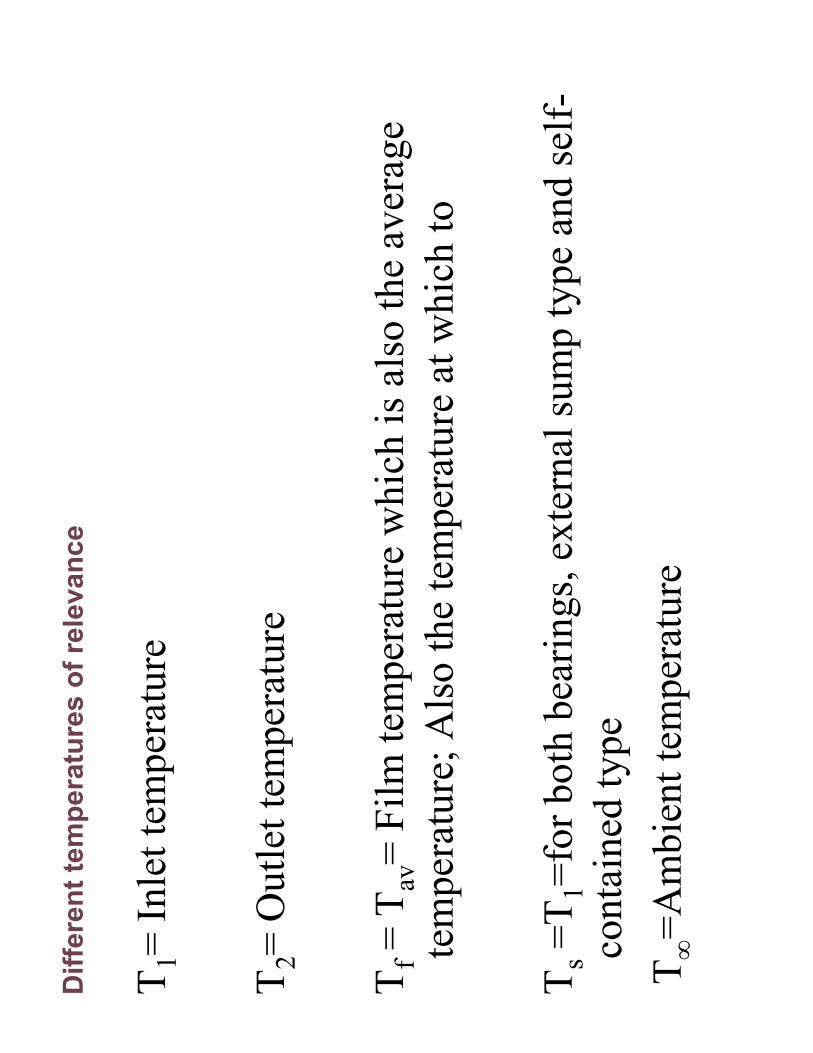
Diffe
rent te
mpera
ture
s o
f re
levance
T1= Inlet temperature
T2= Outlet tem
perature
Tf= T
av= Film tem
perature which is also the average
temperature; Also the temperature at which to
Ts=T1=for both bearings, external sump type and self-
contained type
T∞=Ambient temperature

PETR
OFF’S
EQ
UA
TIO
N:
•Petroffwas the first person to explain the phenomenon of bearing friction
•He assumed that the shaft is concentric hence his theory is not good for actual
bearing which is eccentric when it is running
•Nevertheless, petroff’sbearing theory explains the useful (i) dimensionless groups
(ii) gives an equation for coefficient of friction that is good even for eccentric
bearings
•Petroff’stheory is developed for lightly loaded bearings
∆+
=2T
TT
fi
∆−
=2T
TT
fi
fT

Contd
.2
UrN
hc
πµ
τµ
==
23
24
()(
)(2
)()
rN
rlN
TAr
rlr
cc
πµ
πµ
τπ
==
=
2
()(2
)()
2T
fWr
frlPr
rflP
==
=2
2Nr
fPc
µπ
=2
rN
Sc
Pµ
=
2
22
22
rN
rf
Sc
Pc
µπ
π
=
=
τ=shear
stress,
S=
Som
merf
eld
num
ber; r=radius of the journal; c=radial
clearance between the bearing and journal; r/c=radial clearance ratio; N=speed in
rps; P=pressure in the bearing; W=load on the bearing; T=torque; f=coefficient of
friction; h=film thickness; U=relative velocity of bearing and journal; l=length of
bearing; µ=coefficient of dynamic viscosity
Petr
off’s
equation
(1883)

Contd
.
2j
mlc
Ulc
rNρ
ρπ=
=&
()
()
00
00
2
f
loss
b
UA
TT
QUA
TT
∞
∞
−=
−=
&
gen
pj
pQ
mC
Tlc
rNC
Tρπ
=∆
=∆
&&
()
2
32
22
24
j
gen
jj
jj
Nrl
frc
rc
QTN
fWrN
rWN
rWN
cr
cW
r
µπ
ππ
π
=
==
=
&
23
3
00
16
j
f
Nlr
TT
UAc
µπ
∞=
+(
)0
02
fgen
pj
p
UA
TT
QT
mC
lcrN
Cρπ
∞−
∆=
=& &
area
density
Average velocity
Combined radiation & convention
universal heat transfer coefficient
Bearing surface area
Because the bushing temperature is half-way
between the film temperature and ambient
temperature
Heat generated due to work
done on the lubricant by the
journal

Sta
ble
Lubrication
()
60.36210
jN P
µ−
≥

Thic
k F
ilm
Lubrication
ce=
ε

Hydro
dynam
ic T
heory

Hydro
dynam
ic lubrication e
quations:
0dp
Fp
dxdydz
dxdz
dydxdz
pdydz
dx
yττ
τ
∂
=
++
−+
−=
∂
∑
dp
dx
yτ∂=∂
u yτ
µ∂
=∂
2
2
dp
u
dx
yµ∂
=∂
⇒
Substituting,
1
1u
dpy
Cy
dx
µ∂
=+
∂integrating
Integrating once more,
2
12
1 2
dp
uy
Cy
Cdx
µ=
++
0;
0;
yy
h
uu
U
==
==−
⇒

Som
merf
eld
’sconclu
sio
n
()
12
2
;0
2
1 2Uhdp
CC
hdx
dp
Uu
yhy
ydx
h
µ
µ
=−
−=
⇒=
−−
Uu
yh
=−
When the pressure is
maximum, dp/dx=0, hence
0h
Qudy
=∫
Volume flow rate:
3
212
Uh
hdp
Qdx
µ=−
−
If the lubricant is incompressible, then the volume flow rate issame for all cross-
sections. Hence
0=
dx
dQ

Contd
.
⇒=
−=
012
2
3
dx
dp
h
dxd
dx
dh
U
dx
dQ
µ
3
6d
hdp
dh
Udx
dx
dx
µ
=−
33
6h
ph
ph
Ux
xz
zx
µµ
∂∂
∂∂
∂−
=−
∂∂
∂∂
∂
2r
rN
fc
cPµ
φ
=
Norm
ally difficult to solve this partial differential equation analytically. Sommerfeld
gave a solution in 1904, which can be expressed as

Eff
ective journ
al speed
2
jN
rS
cP
µ
=
2j
bW
NN
NN
=+
−
fW
NN
=
()
22
12
jb
Wb
W
jj
NN
NN
Nr
Sc
PN
N
µ
+−
==
+−
S

Desig
n C
onsid
era
tions
•There are two groups of variables.
•The first group of variables are independent variables and
either given or under the control of the designer.
1) The viscosity, µ
2) The load per unit of projected bearing area, P
3) The speed N
4) The bearing dim
ensions r, c, β
•In the second group are the dependent variables. The
designer can not control these except indirectly by changing
one or more of the first group. These are:
1)
The coefficient of friction f
2)
The temperature rise ∆T
3)
The volume flow rate of oil Q
4)
The minim
um film thickness ho

The d
imensio
nle
ss v
ari
able
s a
nd c
hart
s o
f R
aym
ondi&
Boyd
variable
ess
dim
ensionl
rise
eTem
peratur
pressure
film
maxim
um
of
Position
ratio
pressure
film
Maxim
um
ratio
Flow
variable
Flow
degrees
, thickness
film
minim
um
of
Position
variable
thickness
film
Minim
um
ariable
friction v
of
t coefficien
max
0
=∆=
=
=
=
==
=
P
TCP
PQQrcNl
Qch
crf
p
Ps
θφ

Fir
st:
Contd
.

Absolu
te v
iscosity:
Viscosity with respect to average
temperature
for
various
SAE
grades of lubricants from 10 to 70.
You can use the table 12-1 in
conjunction
with
the
following
equation as an alternative to this
chart.
.lubricants
of
grades
60
-SAE
to
10
-SAE
for
1-12
table
from
obtained
be
may
&0
127
8.1
0 µµµ b
Cin
Te
oT
b
+
=


()
0.120
11
2
c
sj
Trfc
PQ
QrcNl
Q
∆=
−
The value of
“P”
must be substituted
in MPa


Anoth
er
exam
ple
: Itera
tive D
ete
rmin
ation o
f A
vera
ge T
em
pera
ture
of th
e F
ilm
12-11 of Shigley(6ed)

Contd
.
12-21 (Shigley, 6ed)
12-11 of Shigley(6ed)

12-21 (Shigley, 6ed)

Contd
.

Matlab
code for
the p
recedin
g e
xam
ple
:
pause off
%Iterative programmefor the determ
ination of the film
temperature in journal bearning
%from Raymondiand Boyd charts
% This is for SAE30; for other grades the viscosity temperature relation must be appropriately substituted
% The design is for minimum radial clearance scenario
% this computer program is valid only for l/d=1, 1/2 or 1/4
W=3000 %
load on the bearing, in Newtons
N=8 %
journal speed in rps
Ts=60 %
sump temperature in degree centrigrade
lbyd=1 %
the l/dratio
jdia=80 %
nominal diameter of the journal in mm
jtol=-0.01 %
unilateral tolerance (deviation) on journal diameter, m
m;must be a signed quantity
bdia=80.08 %
nominal diameter of the sleeve, in mm
btol=0.03 %
unilateral tolerance (deviation) on bearing diameter, mm; must be a signed quantity
% In minimum clearance design, we look for maximum shaft (journal) and minimum hole (sleeve)
% The radial clearance c is then equal to the cmin, the m
inimum clearance of the fit
%seeking maximum shaft
dmax=max(jdia, jdia+jtol)
%seeking the minimum sleeve diameter
bmin=min(bdia, bdia+btol)
%radial clearance
c=(bmin-dmax)/2
r=jdia/2
%clearance ratio
clratio=r/c

Contd
.%length of the bearing
l=lbyd*jdia
% load per unit projected area of the journal, MPa
P=W/(jdia*l)
% For finding the average temperature of the film
, Tavor Tf, a trial and error procedure is needed
% maximum possible value in the Fig 12-11 is 145 degree centrigrade
%iteration loop begins
deltaT=42 %
2*(145 -Ts)
Tav=Ts+deltaT/2 % This is the trial # 1 for average temperature
dis=Tav-Ts %
or you may assign any value greater than 1
iteration=0
while (abs(dis)>0.2)
iteration=iteration+1
% From Table 12-1 for SAE30, for the current trial of Tav
mu0=0.0971 %
base viscosity, mPa-s
bval=1360 %
degree centrigrade
mu=mu0*exp(bval/(1.8*Tav+127)) %
absolute or dynamic viscosity in milli-Pacal-second, mPa-s.

Contd
.
%temperature rise in the bearing deltaT
deltaT=2*(Tav-Ts)
%sommerfeldnumber
S=((clratio)^2)*(m
u*0.001*N)/(P*10^6)
%From Fig. 12-21, for SAE oils, the second estimate of temperature increase, for l/d=1, dT2 is
dT2=(P/0.12)*(0.349+6.009*S+0.0475*(S^2))
%discrepancy in the estimation of temperature increase
dis=deltaT-dT2
% Now the next trial for Tavcan be made as Tav-dis/2; sign willbeautomatically taken care of
Tav=Tav-dis/2
deltaT=dT2
pause
end
% Now discrepancy being less than one, we can consider the latest trail of Tavas the valid
%hence the T1 and T2 can be estimated as well
T1=Tav-deltaT/2 %
inlet temperature, same as sump temperature Ts
T2=Tav+deltaT/2 %
outlet temperature
iteration

Pro
ble
ms w
ith l/d
ratio o
ther
than 1
, ½
, ¼
or
infinity
•With l/d
ratio falling in between the
marked
values, it is possible to use an equation to
determine at the interm
ediate value of l/d:
()
1
3
12
14
11
11
21
41
21
48
31
11
11
41
12
424
ll
ll
ly
yd
dd
dd
yl
ll
lld
yy
dd
dd
∞
−
−−
−+
−−
=
−
−−
+−
−

Ste
ady-s
tate
conditio
ns i
n s
elf-c
onta
ined b
earings (
als
o c
alled a
s p
illo
w
blo
ck b
earings a
nd p
edesta
l bearings) (
)loss
bQ
UAT
T∞
=−
&
()
fb
bT
TT
Tα
∞−
=−
The value of alpha is usually
taken as 1 otherwise,
for
better accuracy, Table 12-2
can be referred.

Contd
.
()
00
1 1
loss
f
f
b
UA
QT
T
TT
T
α α α
∞
∞
=−
+ +=
+
&
Solving the preceding equation for Tb and substituting in the heat loss rate
gives the following equation in proper variables

Anoth
er
exam
ple
:
•A full journal bearing has a shaft journal w
ith a
diameter of 30 m
m and a unilateral tolerance of
-0.035 m
m. The busing bore is 50 m
m in length.
The bearing load is 2.75 kN
and the journal
rotates
at 1120 rpm. Analyze the
minim
um
clearance assem
bly and find the minim
um film
thickness, the coefficient of friction, and the total
oil flow if the average viscosity is 60 m
Pa-s.

Solu
tion:

Contd
.

Contd
.

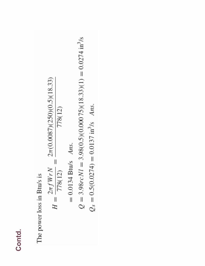
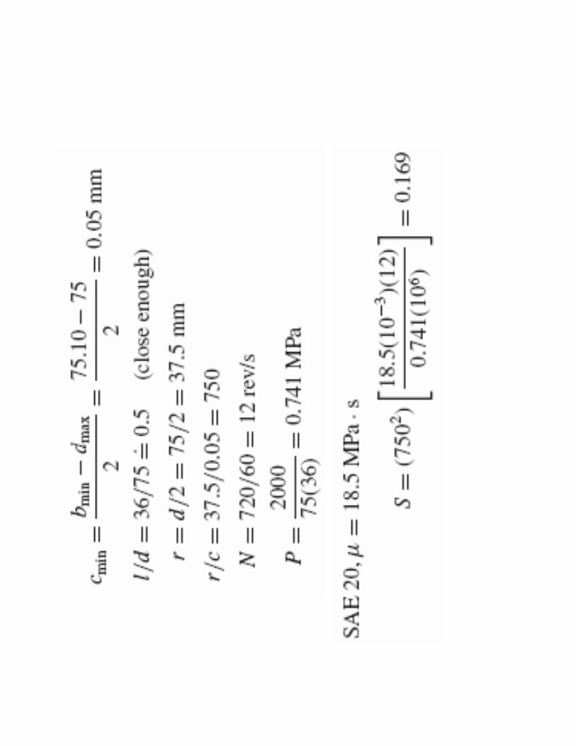
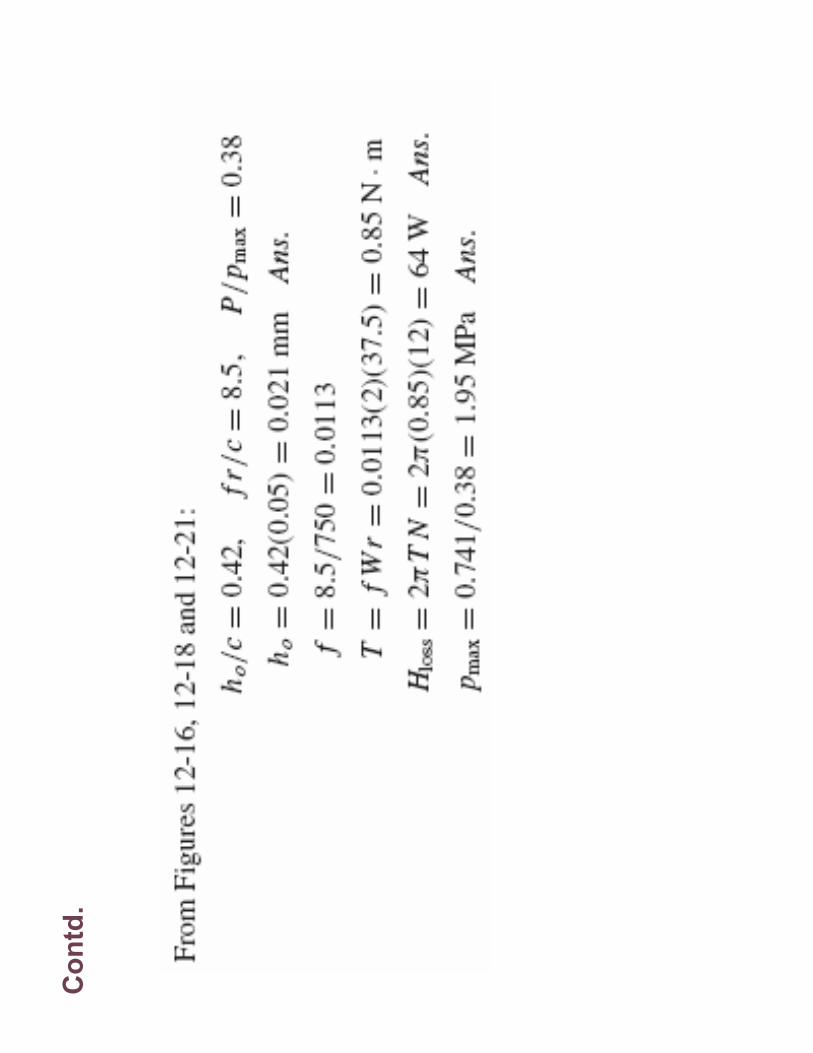
exam
ple
•A journal bearing ha a shaft diameter of 75 m
m
with a
unilateral tolerance of -0.02 mm. The
bushing bore has a diameter of 75.10 m
m w
ith a
unilateral tolerance of 0.06 m
m. The bushing is 36
mm and supports a load of 2 kN. The journal speed
is 720 rpm. For the minim
um clearance assem
bly
find the minim
um film
thickness, the heat loss
rate, and the
maxim
um lubricant pressure for
SAE20 and SAE40 lubricant operating at a an
average film
tem
perature of 60oC.

Contd
.
Contd
.


Fig
. 12.2
6

Fig
. 12.2
7

Fig
. 12.3
2

Fig
. 12.3
3

Fig
. 12.3
4

Fig
. 12.3
5
Fig
. 12.3
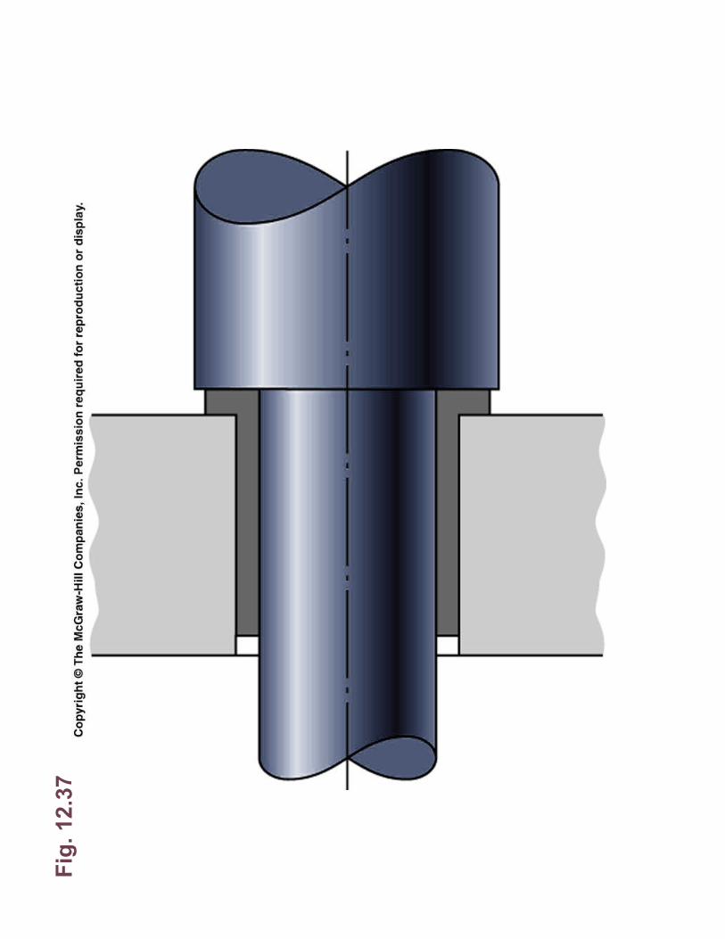
7

Fig
. 12.3
8

Fig
. 12.3
9