Embed Size (px)
Citation preview

Study About Minimum Quantity Lubri�cation inBearing Holes Bored with Pcd Tools in AluminumAlloyPaulo Paiva Carvalho ( [email protected] )
Fiat Research Centre: Centro Ricerche FiatGustavo H. N. Fernandes
Universidade Federal de UberlândiaLucas M. Q. Barbosa
Universidade Federal de UberlândiaFelipe C. R. de Souza
Universidade Federal de UberlândiaJosé A. G. de Sousa
Federal Technological University of ParanáPaulo S. Martins
Fiat Chrysler AutomobilesElhadji H. T. Ba
Federal Technological University of ParanáÁlisson R. Machado
Universidade Federal de Uberlândia
Research Article
Keywords: Aluminum alloys, boring, Minimum Quantity Lubrication, Polycrystalline Diamond tools,sustainable, Green machining
Posted Date: November 2nd, 2021
DOI: https://doi.org/10.21203/rs.3.rs-972806/v1
License: This work is licensed under a Creative Commons Attribution 4.0 International License. Read Full License

STUDY ABOUT MINIMUM QUANTITY LUBRIFICATION IN
ALUMINUM ALLOYS BEARING HOLES
Paulo P. Carvalho a* ; Gustavo H. N. Fernandes b; Lucas M. Q. Barbosa b; Felipe C. R. de Souza b; José A. G. de Sousa c; Paulo S. Martins a; Elhadji H. T. Ba e; Álisson R. Machado b,f
a Fiat Chrysler Automobiles - FCA, Manufacturing Engineering, Betim - MG, Brazil b Universidade Federal de Uberlândia, ,Mechanical Engineering Faculty, Uberlândia - MG, Brazil cFederal Technological University of Paraná – Mechanical Engineering, Londrina - PR, Brazil d Centro Federal de Educação Tecnológica de Minas Gerais, Belo Horizonte - MG, Brazil e Pontifícia Universidade Católica do Paraná, Mechanical Engineering, Curitiba - PR, Brazil
* Corresponding author. E-mail address: [email protected]
Abstract: Cutting Fluid in Abundancy – CFA is a standard cooling technique used in
machining due to the good relationship between quality and productivity. However, due to
sustainability problems, economic, social, and environmental, several research types have
been carried out worldwide about replacing or eliminating these inputs in the cutting process.
In this work, three full factorial Design of Experiment - DoE were used to verify the
performance and feasibility of replacing the Cutting Fluid in Abundance - CFA by Minimum
Quantity Lubrification – MQL during the bearing of holes bored with Polly Cristaline
Diamond – PCD tools in aluminum alloy. The input variables were cutting speed (𝑣𝑐), feed
per knife (𝑓𝑧) and depth of cut (𝑑𝑜𝑐). While output variables were diameter and circularity
deviation. For each machining atmosphere, dry, CFA, and MQL, a full factorial DoE (23)
was performed with test and replicate. A total of 48 runs were performed. The main
conclusion is that MQL showed similar CFA results, as proven by the mean hypothesis test.
Based on the results of this work, it can be affirmed that MQL could replace the CFA
technique.
Keywords: Aluminum alloys; boring; Minimum Quantity Lubrication; Polycrystalline
Diamond tools; sustainable; Green machining.
Statements and Declarat ions The authors have no relevant financial or non-financial interests to disclose.
The authors have no conflicts of interest to declare that are relevant to the content of this article.
All authors certify that they have no affiliations with or involvement in any organization or entity with
any financial interest or non-financial interest in the subject matter or materials discussed in this
manuscript.
The authors have no financial or proprietary interests in any material discussed in this article.
Acknowledgments The authors would like to thanks: the Grupo de Manufatura Sustentável – GMS; the Laboratório de
Ensino e Pesquisa em Usinagem – LEPU at the Federal University of Uberlandia – Brazil, Scanning
Electron Microscopy Laboratory of the School of Chemical Engineering of Federal University of
Uberlandia (FEQUI-UFU) for the SEM analysis, and the Brazilian research agencies CNPq,
FAPEMIG, and Coordenacao de Aperfeicoamento de Pessoal de Nivel Superior - Brasil (CAPES).

2
Declarat ions form
The author(s) is (are) the only responsible for the printed material included in this paper. Furthermore we would like to declare:
a. Consent to participate & Consent for publication:
We herebay, all authors and co-authors below listed, by the meaning of this
statement would like to declare our consentment of participation and our consent
for publication of the article: STUDY ABOUT MINIMUM QUANTITY
LUBRIFICATION IN BEARING HOLES BORED WITH PCD TOOLS IN
ALUMINUM ALLOY.
Author Signature
1 – Paulo Paiva Carvalho (first and corresponding author):
2 – Gustavo Henrique Nazareno Fernandes
3 – Lucas Melo Queiroz Barbosa
4 – Felipe Chagas Rodriguez de Souza
5 – José Aécio Gomes de Sousa
6 – Paulo Sérgio Martins
7 - Elhadji heikh Talibouya Ba
8 – Álisson Rocha Machado (reviewer)

3
1 . Introduct ion
Cutting Fluid in Abundancy – CFA is a standard cooling technique used in machining due
to the good relationship between quality and productivity. CFA plays vital functions in
temperature control, with lubrication and cooling, in addition to removing chips, protecting the
machine-tool-set against oxidation [1]–[3]. Said et al. (2019) [4] estimates that in 2016 alone,
the global consumption of non-biodegradable mineral-based CFs was ~ 13,726 million tons,
with an increasing forecast of increase. According to Benedicto et al. (2017) [5], in 2022,
lubricants' global demand can reach 43.9 million tons.
However, due to sustainability problems, economic, social, and environmental, several
research types have been carried out worldwide about replacing or eliminating these inputs in
the cutting process. For example, according to Tai et al. (2014) [6], the costs for maintenance
and operation of CFA in a Powertrain system can reach 17% of the part manufacturing cost.
Similar values were estimated by King et al. (2001) [7], 7 to 17%. Sharma et al. (2016) state
that this value is between 16 to 20% [8], and for Demirbas & Kobya (2017) [9], it can reach
30% in some particular cases.
Regarding CFAs' social and environmental problems, Shashidhara & Jayaram (2010) [10]
estimate that ~ 80% of machining operators leave are associated with CFA poisoning. This is
because it contains several additives, many of them toxic, such as fungicides and bactericides,
which cause severe damage to human health, such as allergic or respiratory problems,
degenerative diseases, and even cancer [11]. Besides, they cause environmental damage by
contaminating soils, sewers, rivers, and water sources [12], [13].
From the sustainable point of view, Dry Machining - DM, seems to be the most
advantageous method. However, according to Dhar et al. (2006) [14], it is impossible to
perform DM in Aluminum-Silicon alloys' drilling operations due to their high ductility.
Without proper cooling and lubrication, the chip adheres to the tool and can cause it to break
prematurely. Regarding Dry Machining, many authors have performed comparative
performance studies with CFA and MQL. In most cases, MQL results were better in cutting
power, tool wear, surface integrity, temperature, etc. [4], [15]–[17].
MQL has been widely studied as an excellent alternative concerning CFA since it:
(i) combines both cooling and lubricating properties; (ii) reduces initial investment with
machinery, pumping system, filtration, big tanks, CFA cooling machines; (iii) reduces energy,
CFA, and water consumption; (iv) increases chip recycling rate; (v) causes lower
environmental, social and economic impacts; (vi) acts cooling manly the tool, keeping the

4
benefit of high temperatures in the piece that causes material softening, lower shear resistance
and hardness, facilitating the cutting process; (vii) better penetration in tool/piece interface
because of high pressure, and since CFA tends to evaporate before accessing cutting zone;
(viii) lower metallic particles generations; (ix) equal or even better machining performance [4],
[6], [15], [17], [18].
In this work, it was proposed to investigate the use of MQL in the boring operation of
Aluminum-Silicon alloy (AA384) compared to dry and CFA atmosphere. It was used thin-
walled AA384 parts of a motor vehicle transmission housing. This bearing holes investigation
was carried out using the same parameters adopted in an automotive production line. The
diameter and circularity deviation of the hole was chosen as output variables.
1 .1 . Boring operat ion
Wang et al. (2013) [19] and Bhattacharyya et al. (2006) [20] define boring as precision
machining. Its main objective is to widen holes diameter to achieve narrow final tolerances,
such as diameter, deviation of circularity, cylindricality, roughness, and position. It is a
complex operation that requires perfect alignment between pieces/tools. A misalignment
between the actual and the theoretical hole center causes: an unbalance of the cutting forces
due to higher removal of material from the side of the hole about the opposite side; tool
deflection and consequently difficulties in obtaining the finished hole characteristics; variation
in depth of cut at each cutting edge of the tool at each rotation; deflection and alteration of the
tool beat, which also contributes to increased cutting force unbalance [20][21].
Jun et al. (2006) [21] studied the effects of tool beating (misalignment) and cutting force
on machined holes' using a boring bar with four sharp edges. They introduced a maximum
misalignment of 0.1 mm and a beat whose maximum displacement of the tool, measured before
and during the cutting, was 0.2 and 0.1 mm, respectively. It caused variations of 0.08 mm in
diameter in relation to the nominal value and 0.1 mm amplitude in the circularity deviation.
Figure 1 (a) (b) (c) shows the schematic drawing of tool displacement and Figure 1 (e) (f)
shows its effect on boring.
It is noticed, Figure 12 (d), that the tools` displacement decreases during the cutting due
to the restriction imposed by the material but does not reach zero. In addition, this restriction
changes the cutting force due to the depth of cut momentary variation in each cutting edge
responsible for irregular hole machining. Finally, the tool displacement is transferred to the
hole according to vibration frequency, generating quantitative errors such as circularity and
diameter deviations, poor roughness, etc.

5
In finishing holes in Aluminum alloy parts, the boring operation is essential for obtaining
tolerances, usually with H7 adjustment. For example, Bezerra et al. (2001) [22] analyzed the
influence of cutting parameters on the qualitative characteristics of holes with 12 mm in
diameter, using a wider of 11.997 mm of a medium diameter and 140 mm in length. According
to the authors, smaller variations in diameter and circularity deviation occurred at low cutting
speeds. However, these results contradict the literature. At low cutting speeds, there is a higher
probability of forming a Buildup-Edge - BuE, which would lead to more significant variations
in diameter, which would not happen at high cutting speeds.
1 .2 . Minimum Quant i ty Lubri f icat ion - MQL
Minimum Quantity Lubrification (MQL) system works through a jet of a line pressurized
air (5 ~ 15 𝑏𝑎𝑟), which interacts with oil from a reservoir, fragmenting it, and forming a mixture
of pressurized air and micro drops of oil, called a jet. This mixture is then injected into the
Figure 1: Tool displacement and effects. (a) Lateral view; (b) Top view; (c) Schematic representation of the removed chips section area; (d) Tool displacement; (f) Forces before,
during and after boring
Source: Adapted from [20][21]

6
cutting zone by a nozzle, with an approximate diameter of ∅ = 1 𝑚𝑚, assisting the cooling
and lubricating process [23].
There is no literary consensus about the oil flow rate in MQL. Values were found between
0.01 to 2 000 l/h, meanwhile, in CFA it was estimated to be around 1 200 l/h, reaching up to
24 000 l/h [6], [15], [23]–[27]. For instance, Obikawa et al. (2009) [28], using the same
machinery and machining conditions, found a flow rate of approximately 30 l/h of emulsifiable
cutting fluid ( 8 to 10% v.v.), while for MQL, it was 10 to 100 ml/h.
Figure 2 shows an example of an external MQL system with an ejector nozzle adapted
for turning operation used by Marques et al. (2017) [29]. The most common oils used in MQL
are vegetable, esters, or synthetic fluids due to more excellent physical-chemical stability at
high pressures, greater fluidity, and more remarkable anti-wear ability [24].
According to Sharma et al. (2016) [8], the MQL can be divided regarding the application
way into two categories, internal (single or double channel) or external (conventional or
ejector), as shown in Figure 3. In the case of internal application, Figure 3 ( 1 ) (2 ) , i t is
done inside the tool with channels designed for this purpose. Boswell et al. (2017) [15] explain
that the internal channels can be simple, where oil and air are mixed along with the tool and
before being injected, or dual channels in which oil and air are atomized just before the cutting
zone.
Figure 2: Layout of an external MQL system with ejector nozzle used in turning
Source: adapted from [29]

7
In the external MQL with a conventional nozzle, Figure 3 ( 3 ) ( 4 ) , the oil/air mixture is
made first in an atomizer and later delivered to the nozzle. Finally, in the ejector nozzle, the
mixture is made just before being injected. Of the four forms, the one with the best results is
the internal atomization by double channel. This technique is mostly favorable for processes
where access to the cutting zone is practically impossible, such as drilling, threading, or
widening operations.
According to Tai et al. (2014) [6], the Ford Motor Company launched its first production
line using MQL in 2005 at the United States factory. Due to the successful application for
prismatic components, such as cast-iron block, heads, crankshaft, motor block, and Aluminum
alloy transmission housings, MQL machining has become standard for acquiring new
production lines, being included in the BOP list1 (Bill Of Process).
Two atmospheres, dry and MQL, were studied by Khettabi et al. (2017) [16] during high-
speed milling of three types of Aluminum Alloys, 2024, 6061, and 7075. Input variables were,
dry and MQL (7, 14, 21 and 28 mm3/s), cutting speed (300 ~1 500 m/min) with constant feed
of 0.055 (mm/rev) and depth of cut (1.0 mm). The output variables analyzed were cutting
1 BOP (Bill Of Process) is a descriptive of the process that contains the best practices and worldwide standards of performance, quality and productivity, being, therefore, used as standard of acquisition of processes.
Figure 3: Ways of MQL: (1) Internal single channel; (2) double channel; (3) external ejector nozzle; (4) conventional nozzle.
Source: Adapted from [6], [15], [43]

8
forces, particle emission, and surface finish. MQL performed better in terms of forces and
surface finish but worse for particle emission.
Jayal et al. (2007) found more significant cylindricity error deviations to the nominal
diameter of 12 mm when applying dry machining during the drilling of cast Aluminum alloy
in comparison to MQL. The deviations found were approximately 0.01500 mm for the MQL
technique and a 0.01575 mm deviation for DM.
Thus, there is an excellent appeal for the use of MQL. However, even with superior
performance concerning dry machining and, in many cases, also to CFA, the effects of
overheating can influence the quality of products, especially those manufactured in aluminum
alloy, which limits or even prevents the use of the MQL on a large scale in industrial processes.
Furthermore, CFA's cooling effect is much higher than MQL due to its thermal properties, such
as specific heat (CP). The air, water, and oil CP values are, respectively: 1.04 kJ/kgK, 4.18
kJ/kgK, and 1.92 kJ/kgK [30]. For this reason, the success of using the MQL in substitution to
CFA depends on the correct choice of machining factors.
1 .3 . Aluminum al loys
Aluminum alloys are of significant and increasing importance materials, as it has: (i)
exceptional strength-to-weight ratio (ii) high corrosion resistance; (iii) good mechanical
properties (iv) excellent thermal and electrical conductivity; (v) good machinability; (vi) low
melting point; (vii) abundantly available in the Earth crust [31], [32]. These properties make
them widely used in virtually all kinds of industries and purposes, including automotive,
aerospace, naval, electronic, medical, electromechanics, civil, electrical, among others [31].
For example, the total amount of aluminum parts in a European car in 2012 was estimated at
around 140 kg [33]; today, this value is nearly 180 kg, expected to reach 250 kg in 2025 [31]
example of the applicability of this light metal [32].
Aluminum-Silicon alloy is of great relevance, mainly due to the Al-Si eutectic presence's
high fluidity. According to Yan et al. (2013) [34], the Al-Si2 alloy is an essential Al-Si series
used in engine manufacturing blocks, heads, pistons, etc. According to these authors, silicon
acts as a vital reinforcement by forming lamellae distributed in the ductile matrix. In this way,
the physical and mechanical properties of the Al-Si alloy are influenced by the morphology,
volume fraction, and specific mechanical and physical properties of eutectic silicon. Other
elements added to the Al-Si system produce important molten alloys: AI-Si-Cu, AI-Si-Mg, AI-
Si-Cu-Mg, AI-Si-Cu-Fe. The addition of copper contributes to strength, and silicon improves
moldability and increases the final product's abrasion resistance [35].

9
Alloys with high silicon content usually are used in the casting of more complex products
in permanent matrices. A1-Si-Cu/Mg alloys with more than 3 – 4 % copper or magnesium are
heat treatable. According to Asghar, Requena, and Kubel (2010) [36], adding copper and
magnesium in Al-Si alloys improves its mechanical resistance at room temperature due to its
formation of precipitates of Mg2Si and Al2Cu. However, this effect of precipitation hardening
reduces when these alloys are exposed to temperatures above 150 ºC. Alloys with high silicon
content (> 12% Si) have a less thermal expansion, giving an advantage in high temperatures.
When the silicon content exceeds about 12-13%, the crystalline structure has primary silicon
crystals dispersed in the eutectic structure. When these crystals are evenly distributed, the
product tends to have excellent wear resistance [35].
According to Couto et al. (2010, apud Parreira, 2014) [37], [38], the alloys of the Al-Si
system, in general, have, in addition to high fluidity, low shrinkage in castings, high resistance
to corrosion, good weldability, easy brazing and low coefficient of thermal expansion.
Furthermore, for Requena et al. (2009) [39], eutectic silicon substantially improves the
Aluminum alloy properties due to the transfer of charge from the ductile Aluminum alloy
matrix to the hard silicon particles.
Kishawy et al. (2005) state that the silicon percentage also influences the alloy's
machinability. Since that, its particles have a greater hardness than any other microstructure
phase. In this way, abrasion becomes the tool's primary wear mechanism as the average
temperature in the cutting zone does not exceed the alloy's melting point (on average 650 ºC).
Even close to this temperature, cutting tools would not be influenced by thermally activated
wear.
Niknan, Zedan, and Songmene (2014) [40] affirm that the machining of aluminum alloys,
although classified as easy machining about tool wear and cutting power, becomes more
difficult due to the tool wear abrasion caused by particles of hard silicon. Bezerra et al. (2001)
[22] also comment that the more excellent resistance to abrasion conferred by Si contributes to
increased tool wear and, consequently, to the machining process's cost. Yan et al. (2013) [34]
state that Al-Si alloys are more susceptible to the formation of a Built-up Edge (BuE) both on
the rake and flank face, mainly with materials that have a chemical affinity with the aluminum
alloy. Coz et al. (2012) [41] studied the influence of cutting geometry on dry milling of
aerospace Aluminum alloy AA7075 - AlZnMgCu1.5 and found adhesion as the primary wear
mechanism due to higher cutting temperatures.
Regarding the tool’s material, PCD (Polycrystalline Diamond) has been recognized for its
high performance due to the possibility of using High-Speed Machining - HSM without
10
affecting the tool’s life. Furthermore, the properties of PCD depend on the size of the diamond
grain, which provides more excellent resistance to abrasion since the hardness of the silicon
particles is lower than that of the diamond, this being the critical point to justify the high
performance of PCD boring tools [34].
2 . Mater ia ls & Methods
2 .1 . Design of Exper iments (DoE) and procedures
Three full factorial Design of Experiment - DoE with three variables in two levels (±) (3𝑥 (23)) were used to verify the performance and feasibility of replacing the CFA with MQL.
The input variables were: cutting speed (𝑣𝑐), feed per knife (𝑓𝑧), and depth of cut (𝑑𝑝). For
each atmosphere, DM, CFA, and MQL, a DoE (23) was performed with a test and replicate.
A total of 48 runs were performed, as shown in Tables 3 and 4. The parameter values were
based on the data used in the automotive industry production line.
A variance analysis (ANOVA) and a hypothesis tests were used to plan and analyze results
using Minitab software version 17. A significance level(α) of 0.05 was defined in the bilateral
t-test for comparing diameter and circularity deviation. A hypothesis test was proposed for
MQL, CFA, and DM as following:
𝐻0: 𝜇𝑀𝑄𝐿 = 𝜇𝐶𝐹𝐴 𝑜𝑟 𝜇𝐷𝑀 for the case, MQL diameter and circularity deviation is
statistically equal to CFA or DM;
𝐻1: 𝜇𝑀𝑄𝐿 ≠ 𝜇𝐶𝐹𝐴 𝑜𝑟 𝜇𝐷𝑀 for the case, MQL diameter and circularity deviation is
statistically different from CFA or DM. The following assumptions were stated:
(i) The data represent random samples from normal populations;
(ii) 𝑦𝑡𝑖 = �� + (��𝑡 − ��) + (𝑦𝑡𝑖 − ��𝑡); where i=1, 2,…,𝑛𝑡;
(iii) 𝜀𝑡𝑖 = 𝑦𝑡𝑖 − ��𝑡𝑖 and 𝜀𝑡𝑖 are independent; identical and randomly distributed with
𝑁(0, 𝜎2). Thus, values higher than the significance level indicate the impossibility of rejection of
the null hypothesis (H0), i.e., indicate that the results of both samples under study are part of
the same population, and, therefore, there is no difference between the results. For values
greater than 0.05, it is possible to affirm a difference between the tests' means.
11
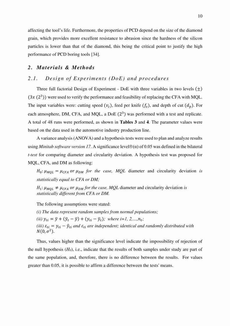
Table 3: Values of each level for the factors VC, fZ e ap
Factor Level
-1 1 𝒗𝒄(m/min) 842 1263 fZ (mm/rev) 0.15 0.30 dp (mm) 0.40 0.65
Table 4: Complete full factorial planning (23) with a replicate
Standard
Order
Execution
order
VC (m/min)
fZ
(mm/rev) ap (mm)
Atmosphere (A)
3 1 842 0.30 0.40
MQL, DM or
CFA
14 2 1263 0.15 0.65 2 3 842 0.15 0.65 6 4 1263 0.15 0.65 9 5 842 0.15 0.40
13 6 1263 0.15 0.40 5 7 1263 0.15 0.40
16 8 1263 0.30 0.65 11 9 842 0.30 0.40 8 10 1263 0.30 0.65
12 11 842 0.30 0.65 15 12 1263 0.30 0.40 10 13 842 0.15 0.65 7 14 1263 0.30 0.40 4 15 842 0.30 0.65 1 16 842 0.15 0.40
2 .2 . Measuring procedures
The circularity and diameter deviation was measured at 16.5 mm from the reference plane,
Figure 4, using eight equally distributed touches. A template containing the angular division
markings was positioned over the hole to ensure equity, reference the cylindrical and angular
reference holes. The least-squares technique was adopted to measure the circularity deviation
because it is the most recommended form by the equipment manufacturers because of the
controlled characteristic. Also, the holes' diameter was measured, with a nominal value of
67+0.03 mm, measured in the same places of the circularity deviation and with the same number
of touches.
Figure 4: Diameter and circularity measurement distance from the reference plane. Dimensions in mm.
12
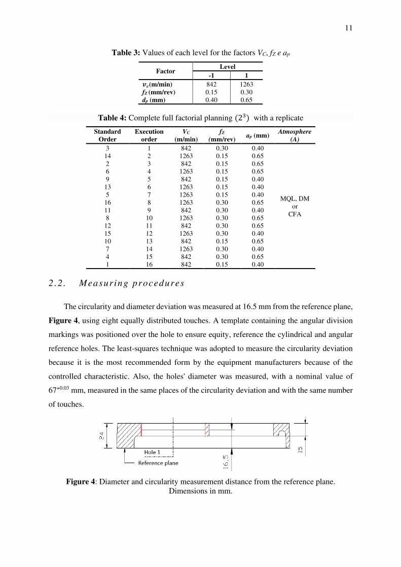
The hole in question is the same finished in the industry with a 67+0.03(H7) mm diameter
and a circularity deviation of 0.015 mm. Figure 5 (a) shows the production part's drawing and
identifying the hole chosen for analysis. The specimens were generated from the cut of the top
of the piece, as shown in Figure 5 (b).
Figure 5: a) transmission housing design with identification of bearing hole chosen for
analysis, b) Specimens extracted from production parts
Table 5 shows the measurements made for the diameter and circularity deviation of the
hole under study. The cutting fluid application was made through three nozzles positioned at
approximately 120º for cooling with CFA and with two nozzles positioned at approximately
180º for machining with MQL. After assembly, the tool beat was measured using a comparator
clock with 0.001mm resolution. The beat found was 0.015 mm.
Table 5: Results of diameter and circularity deviation obtained in the machining of thinning of the hole
ap (mm) 0,40 0,65
Ø C Ø C
Average (mm) 66.204 0.041 65.696 0.032
Standard deviation (mm) 0.032 0.013 0.016 0.014
Maximum (mm) 66.277 0.067 65.720 0.067
Minimum (mm) 66.181 0.013 65.667 0.013
Range (mm) 0.096 0.054 0.053 0.054
Ø: diameter and C: circularity deviation, both measured in millimetres (mm)
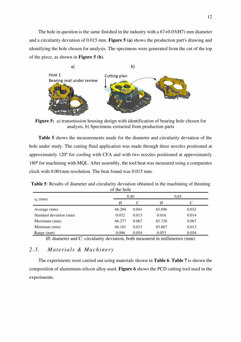
2 .3 . Mater ia l s & Machinery
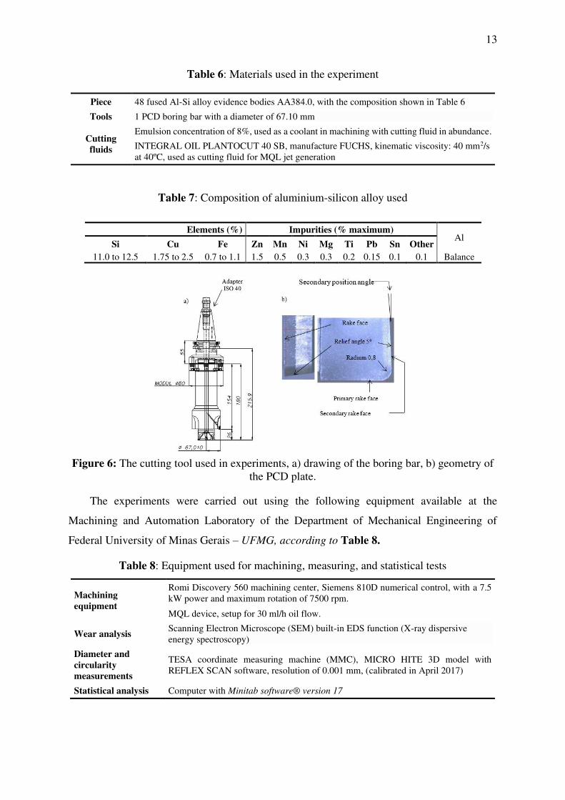
The experiments were carried out using materials shown in Table 6. Table 7 is shown the
composition of aluminium-silicon alloy used. Figure 6 shows the PCD cutting tool used in the
experiments.
13
Table 6: Materials used in the experiment
Piece 48 fused Al-Si alloy evidence bodies AA384.0, with the composition shown in Table 6
Tools 1 PCD boring bar with a diameter of 67.10 mm
Cutting
fluids
Emulsion concentration of 8%, used as a coolant in machining with cutting fluid in abundance.
INTEGRAL OIL PLANTOCUT 40 SB, manufacture FUCHS, kinematic viscosity: 40 mm2/s at 40ºC, used as cutting fluid for MQL jet generation
Table 7: Composition of aluminium-silicon alloy used
Elements (%) Impurities (% maximum) Al
Si Cu Fe Zn Mn Ni Mg Ti Pb Sn Other
11.0 to 12.5 1.75 to 2.5 0.7 to 1.1 1.5 0.5 0.3 0.3 0.2 0.15 0.1 0.1 Balance
Figure 6: The cutting tool used in experiments, a) drawing of the boring bar, b) geometry of
the PCD plate.
The experiments were carried out using the following equipment available at the
Machining and Automation Laboratory of the Department of Mechanical Engineering of
Federal University of Minas Gerais – UFMG, according to Table 8.
Table 8: Equipment used for machining, measuring, and statistical tests
Machining
equipment
Romi Discovery 560 machining center, Siemens 810D numerical control, with a 7.5 kW power and maximum rotation of 7500 rpm.
MQL device, setup for 30 ml/h oil flow.
Wear analysis Scanning Electron Microscope (SEM) built-in EDS function (X-ray dispersive energy spectroscopy)
Diameter and
circularity
measurements
TESA coordinate measuring machine (MMC), MICRO HITE 3D model with REFLEX SCAN software, resolution of 0.001 mm, (calibrated in April 2017)
Statistical analysis Computer with Minitab software® version 17

14
3 . Resul ts & Discuss ion
3 .1 . Diameter Analys is
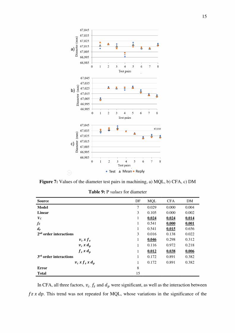
Figure 7 (a) (b) (c) shows the values of the pairs tested for atmosphere MQL, CFA, and
DM, respectively. Figure 7 (a) shows good repeatability between the test and replica values,
except for pair 1 (parts 1 and 9), whose difference was 0.011 mm. In the CFA test, Figure 7
(b), using the lowest cutting parameters, 𝑣𝑐 and 𝑑𝑝. Diameter values obtained for pair 1 (parts
1 and 9) were smaller than the tool's diameter. Similarly, Yan et al. (2013) [34], where the
hole’ diameter obtained in one of the tests was smaller than the tool's diameter with a
combination of low cutting speed, depth of cut, and high feed. MQL, Figure 7 (a), also
presented diameter values smaller than the tool's diameter in pair 4 (parts 5 and 16). Also, these
values correspond to the combination of the lowest cutting parameters, 𝑣𝑐 (842 m/min), fZ (0,15
mm/rev) e ap (0,4 mm.).
It is also noticed a similar behavior of diameter reduction with the increase of the cutting
parameters between CFA and DM, pairs 4 and 5, which correspond, in general, to the
combinations of the highest cutting parameters considered, mainly 𝑣𝑐 (1 263 m/min) and fZ
(0,30 mm/rev). The data show that the CFA values are lower than those achieved by dry
machining, which proves the influence of refrigeration on the machining process.
Table 9 shows the P-Value values relative to variance analysis (ANOVA) for each
atmosphere. Significant P-Value values lower than the adopted level, 𝛼 = 0.05 , were
highlighted in Table 9 to facilitate visualization.
15
Figure 7: Values of the diameter test pairs in machining, a) MQL, b) CFA, c) DM
Table 9: P values for diameter
Source DF MQL CFA DM
Model 7 0.029 0.000 0.004 Linear 3 0.105 0.000 0.002 VC 1 0.024 0.024 0.014
fZ 1 0.541 0.000 0.001
dp 1 0.541 0.015 0.656 2nd order interactions 3 0.016 0.138 0.022 𝒗𝒄 𝒙 𝒇𝒛 1 0.046 0.298 0.312 𝒗𝒄 𝒙 𝒅𝒑 1 0.116 0.972 0.218 𝒇𝒛 𝒙 𝒅𝒑 1 0.012 0.038 0.006
3rd order interactions 1 0.172 0.891 0.382 𝒗𝒄 𝒙 𝒇𝒛 𝒙 𝒅𝒑 1 0.172 0.891 0.382
Error 8 Total 15
In CFA, all three factors, 𝑣𝑐 , 𝑓𝑧 and 𝑑𝑝 were significant, as well as the interaction between 𝑓𝑧 𝑥 𝑑𝑝. This trend was not repeated for MQL, whose variations in the significance of the

16
factors demonstrate the difference in machining behavior concerning CFA. In MQL, the factors
with the most significant influence were: 𝑣𝑐 and the interactions between 𝑣𝑐 𝑥 𝑓𝑧 and 𝑓𝑧 𝑥 𝑑𝑝.
Dry machining showed significance for 𝑣𝑐 𝑥 𝑓𝑧 and 2nd order interaction between 𝑓𝑧 𝑥 𝑑𝑝.
Figure 8 (a) (b) (c) shows the factors that presented statistical significance for machining
with MQL, CFA, and DM, respectively.
When using MQL, Figure 8 (a), the diameter tends to increase about 0.006 mm with an
increase in 𝑣𝑐 . In addition to the second-order interactions, there is an increase in the diameter
of 0.15 mm with an increase from 𝑣𝑐 and 𝑓𝑧 . The diameter reduction is related to the
combination of larger 𝑓𝑧 an 𝑑𝑝. In MQL and CFA techniques, it is noted that the cutting speed
exerts the same influence, i.e., the diameter increase with the cutting speed, on average of 0.005
mm for both techniques. However, these results are contrary to those found by Yan et al. (2013)
[39] when machining Aluminum-Silicon alloy with a boring bar with a diameter of 33 mm
and 6 cutting edges. These authors found a tendency to reduce the diameter with the increase
of the cutting speed in all the feed ranges studied, although the diameters were always larger
than the tool's diameter, except in one of the tests.
Bezerra et al. (2001) [21] found using a 12 mm diameter and 8 cutting edges, the same
ratio of diameter increases with the increase in cutting speed (Figure 8 (a) (b)) in the machining
of Aluminum-Silicon alloy boring for both speed and feed. The increase in cutting speed causes
an increase in both the cutting temperature and the tool beat increase, generating larger
diameters. As found in the literature, MQL produces higher cutting temperatures than CFA. It
was expected to find in this work larger diameters for MQL. However, the results were similar,
although not all cutting parameters were significantly equal for both atmospheres.
Regarding the feed rate, the results found by Yan et al. (2013) [39] showed an alternation in
the tendency to increase or decrease depending on the rotation (cutting speed) adopted.
However, comparing results with the same rotation range (4000 and 6000 rpm), the increase in
the feed caused an increase in diameter, contrary to that found in the present study.
Similar results were found by Bezerra et al. (2001) [22] for feed, i.e., higher feed tends to
reduce the diameter. It happens because high feed reduces the contact time with the part, which
reduces the effects of heating caused by the cutting speed, besides contributing to the increase
of the tool's contact area, which would influence the cut's stability. It can be verified by
analyzing the combination with fZ and 𝑑𝑝 in both the MQL and CFA. The use of the highest
feed with the highest depth of cut resulted in smaller diameters.

17
Figure 8: Linear significant parameters and second-order interactions on the diameter in the machining technique, a) MQL, b) CFA, c) DM
The final effect of similarity in the behavior between CFA and DM is the significant feed
contribution reducing the diameter, compared with the lower influence of the increase in
diameter due to the cut speed and depth of cut. It can be confirmed by the P-Value presented
in Table 9 for DM, whose contribution percentage is 72.01% for the feed, against 6.66% of 𝑣𝑐 ,
8.26% of 𝑑𝑝 and 5.23% of 𝑓𝑧 𝑥 𝑑𝑝, as calculated by Equation (Eq.) 1.
𝑐𝑜𝑛𝑡𝑟𝑖𝑏𝑢𝑡𝑖𝑜𝑛 (%) = 𝑆𝑢𝑚 𝑜𝑓 𝑖𝑛𝑑𝑖𝑣𝑖𝑑𝑢𝑎𝑙 𝑠𝑞𝑢𝑎𝑟𝑒𝑠𝑆𝑢𝑚 𝑜𝑓 𝑡𝑜𝑡𝑎𝑙 𝑠𝑞𝑢𝑎𝑟𝑒𝑠 (1)
DM showed significant factors like CFA, except for cutting speed, which presented
inverse behavior. This inversion in the diameter behavior with the increase in cutting speed

18
may be related to the reduction of torque and thrust due to the increase in cutting temperature,
which reduces cutting and feed forces because of reducing the material's mechanical strength.
Thus, with lower acting forces, the lower the effect of the vibration generated in the cut
and, consequently, the greater the cut's stability. This effect was observed in DM because at
low cutting speeds and advances, the diameter increases about 0.023 mm of the tool diameter,
reducing this increase to about 0.013 mm of the tool diameter, especially when considering the
combined effect of 𝑓𝑧 𝑥 𝑑𝑝 . In this case, the smallest diameter values were found when
combined with the highest value of 𝑑𝑝.
The increase in 𝑓𝑧 causes an increase in chip thickness, which makes cutting more
effective. A similar result was also obtained by Wang et al. (2013) in the tests carried out on
the aluminium-silicon alloy boring. The authors concluded that silicon particles present in the
aluminium alloy matrix would be more easily cut than plucked due to reduced mechanical
resistance caused by increased temperature.
3 .2 . Roundness Analys is
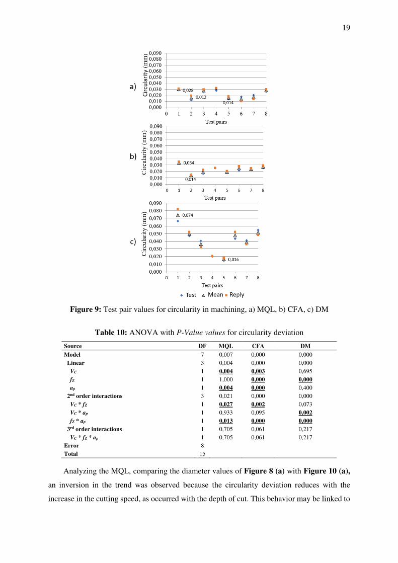
Figure 9 (a) (b) (c) shows the cylindricality results of the test pairs for machining with
MQL, CFA, and DM, respectively. For machining with MQL, a more significant difference
was observed between the pair test values about the other techniques used, with an average of
0.007 mm. Pair 1 presented one of the highest values of circularity deviation associated with
the diameter behavior, pair 1, which presented a value below the tool diameter, as shown in
section 3.1.
Better repeatability between values was observed for CFA, but most values were above
the tolerance specified for the circularity deviation (0.015mm). For DM, it is noted that the
lowest mean value, 0.016 mm, and the highest average value found of 0.074 mm,
corresponding to the lowest values of VC (842 m/min) and dp, (0.4) mm.
Table 10 shows the values of variance analysis, ANOVA, for the studied techniques,
whose P-Value values are lower than the established significance level, 𝛼 = 0.05, denote the
statistical significance of the cut-off parameter.
CFA significant parameters were the same as for the diameter, i.e., 𝑣𝑐 , 𝑓𝑧 , 𝑑𝑝 and
combinations 𝑣𝑐 𝑥 𝑓𝑧 and 𝑓𝑧 𝑥 𝑑𝑝. For MQL, the significant factors were 𝑣𝑐 , 𝑑𝑝 and interactions 𝑣𝑐 𝑥 𝑓𝑧 and 𝑓𝑧 𝑥 𝑑𝑝. For dry machining only 𝑓𝑧 was significant, and the interactions 𝑣𝑐 𝑥 𝑑𝑝and 𝑓𝑧 𝑥 𝑑𝑝.
19
Figure 9: Test pair values for circularity in machining, a) MQL, b) CFA, c) DM
Table 10: ANOVA with P-Value values for circularity deviation
Source DF MQL CFA DM
Model 7 0,007 0,000 0,000 Linear 3 0,004 0,000 0,000 VC 1 0,004 0,003 0,695
fZ 1 1,000 0,000 0,000
ap 1 0,004 0,000 0,400 2nd order interactions 3 0,021 0,000 0,000 VC * fZ 1 0,027 0,002 0,073 VC * ap 1 0,933 0,095 0,002
fZ * ap 1 0,013 0,000 0,000
3rd order interactions 1 0,705 0,061 0,217 VC * fZ * ap 1 0,705 0,061 0,217 Error 8 Total 15
Analyzing the MQL, comparing the diameter values of Figure 8 (a) with Figure 10 (a),
an inversion in the trend was observed because the circularity deviation reduces with the
increase in the cutting speed, as occurred with the depth of cut. This behavior may be linked to

20
aluminium alloy's addition on the cutting edge and the occurrence of a BuE, especially at low
speeds, which would cause an increase in the deviation of the circularity of the hole. As BuE
tends to reduce with the increase of 𝑣𝑐 , the circularity deviation tends to reduce.
The reduction of the circularity deviation with the increase of the depth of cut using MQL
is related to the increase of chip thickness. The analysis of the interaction between 𝑓𝑧 and dp
can confirm it because the lowest circularity deviation values were obtained with these
parameters' highest values. Similar results were found by De Chiffre et al. (2009) [42] in five
different cutting conditions, using MQL, with external application. It was tested a combining
of two levels of cutting depth (p = 0.1 and 0.05 mm) with two feed levels (𝑓𝑧 = 0.3 and 0.2
mm/rev). Among other results pointed out by the authors, the use of low values of dp such as:
0.05 mm are not recommended due to the reduction of chip thickness increasing the probability
of chip breaks, depending on the radius of the tool's hadl.
CFA results showed the opposite trends concerning MQL for cutting speed. However, at
the lowest cutting speed, the value of circularity deviation is similar, i.e., both machining starts
with average values between 0.020 and 0.026 mm, and CFA the values tend to increase with
the cutting speed. In this range, there was an increase in the circularity deviation with the
increase in cutting speed.
For the DM, the increase of the circularity deviation with the increase of 𝑓𝑧 of about 0.02
mm, a value higher than the tolerance itself. This result is opposite to that found for the
diameter, which tends to reduce with increased 𝑓𝑧 . This reversal in trends is exceptionally
harmful to the process because it hinders the adjustment of parameters since both deviations of
circularity and diameter define the product's qualitative characteristics.
3 .3 . Performance Analys is o f Atmosphere (MQL, CFA, and
DM)
Figure 12 (a) (b) (c) shows the optimized values for the three machining techniques,
MQL, Fluid, and Dry, respectively. Considering that machining performance should be
considered for both characteristics, the values were adjusted simultaneously to minimize the
deviation of circularity and the target value for the diameter of 67.015mm, using the "optimized
response" function of the Minitab® version 17.

21
Figure 10: Significant parameters for linear and second-order circularity, a) MQL, b) CFA, c) DM
By comparative analysis of the three graphs' values, it is noted that MQL performed better
than CFA and DM. For the adjusted values, it would be possible to use the maximum cutting
parameters for machining with MQL, which would result in a shorter machining time, 0.5
seconds. For fluid machining, optimized cutting parameters would result in a machining time
of 0.75 seconds, depending on the use of the lowest value for 𝑣𝑐 .
Regarding DM, the optimized results were above the tolerance established for the
circularity deviation and at the upper limit for the diameter, whose values were 0.0163 mm for
the circularity deviation and 67.0297 mm for the diameter. In the tested pairs 4 and 5, the
circularity deviation values were between 0.015 and 0.021 mm, reducing the optimized
calculated values.

22
Figure 12: Cutting parameters optimized for diameter and circularity for machining, a)
MQL, b) CFA, c) DM. Two hypothesis tests were performed, which evaluated each technique's data to compare
machining techniques' performance and the possibility of substitution, especially between the
machining with MQL and Fluid. Table 11 shows the mean, standard deviation, maximum, and
minimum calculated for diameter and circularity deviation in each machining technique.
Table 11: Diameter data and circularity deviation for calculation of the mean hypothesis test
Diameter Circularity deviation
MQL CFA DM MQL CFA DM
Average 67.014 67.019 67.031 0.021 0.022 0.043 Standard Deviation 0.007 0.009 0.007 0.007 0.007 0.018 Maximum 67.022 67.031 67.043 0.031 0.035 0.082 Minimum 66.996 67.002 67.020 0.010 0.012 0.015

23
Table 12 shows the calculation of the mean hypothesis tests for the MQL versus Fluid and
MQL versus Dry techniques for diameter and circularity deviation. The P-Values greater than
the level of significance adopted, α = 0.05, indicates the impossibility of rejection of the null
hypothesis, H0, i.e., as established in the DoE. Thus, it is concluded that the values found for
both diameters and circularity deviation with MQL and CFA are part of the same population
and, therefore, are interchangeable, which means that both techniques are compatible and MQL
can replace CFA.
Table 12: P-Value results for the test of mean hypotheses for diameter and circularity deviation
The P-Values less than 0.05 indicate the rejection of the null hypothesis and, consequently,
the alternative hypothesis, H1. It means that the values found for the MQL and Dry techniques
do not belong to the same population and are therefore not interchangeable. It means that DM
could not replace MQL.
4 . Conclusions
In this work, three full factorial Design of Experiment - DoE with three variables in two
levels (±) (3𝑥 (23) were used to verify the performance and feasibility of replacing the CFA
by MQL. The input variables were: cutting speed (𝑣𝑐), feed per knife (𝑓𝑧), and depth of cut (𝑑𝑝). The output variables were diameter and circularity deviation. For each atmosphere,
dry, CFA, and MQL, a DoE (23) was performed with a test and replicate. A total of 48 runs
were performed. The main conclusions were:
• The cutting speed (𝑣𝑐), was the significant standard parameter between machining
techniques for both diameter and circularity deviation, except for the circularity
deviation in dry machining;
• Diameter tends to increase with increasing cutting speed for machining with MQL and
Fluid and reduce for dry machining;
Feature Analysis Hypothesis tried P-Value
Diameter
MQL x CFA H0: µMQL = µFluido
H1: µMQL ≠ µFluido 0,073
MQL x Seco H0: µMQL = µSeco
H1: µMQL ≠ µSeco 0,000
Circularity deviation
MQL x CFA H0: µMQL = µFluido
H1: µMQL ≠ µFluido 0,429
MQL x Seco H0: µMQL = µSeco
H1: µMQL ≠ µSeco 0,001

24
• The circularity deviation tends to reduce with increasing cutting speed for machining
with MQL and increase with increasing cutting speed for dry machining;
• The feed rate (𝑓𝑧), was the parameter that exerted the most significant influence to the
cutting speed, regardless of the trend, both for the diameter and for the circularity
deviation;
• The diameter tends to reduce, increasing the feed per knife when using CFA and DM.
An inverse situation occurred with the circularity deviation because the increase in
the feed per knife caused an increase in the circularity deviation;
• The depth of cut was the most significant variable for the circularity deviation in MQL
and DM. There was a tendency to decrease with the increase of depth of cut, possibly
due to the more excellent stability generated in the cut due to the increase in chip
thickness and consequent reduction of tool vibration;
• The depth of cut was the least significant variable but presented great second-order
interaction with 𝑣𝑐 and 𝑓𝑧;
• MQL showed similar results to CFA, as proven by the mean hypothesis test. The
optimized cutting parameters for the deviation of circularity and diameter were within
the specified tolerances, resulting in a shorter cutting time, 0.5s for MQL and 0.75s
for CFA. Consequently, MQL was more productive than CFA, considering the
conditions tested;
• Finally, based on this work's results, it can be affirmed that MQL could replace the
CFA technique.
References
[1] E. M. Trent and P. K. Wright, (2000) Metal cutting. Butterworth-Heinemann,. [2] A. R. Machado, A. M. Abrão, R. T. Coelho, and M. B. Da Silva, (2011) “Teoria da
Usinagem dos Materiais [Theory of Materials’ Machining].” Edgard Blucher, São Paulo [In Portuguese].
[3] F. Klocke, (2011) “Manufacturing Processes 1 Cutting Translated by Aaron Kuchle,” in Library of Congress Control, no. 2011925556.
[4] Z. Said et al., (2019) “A comprehensive review on minimum quantity lubrication (MQL) in machining processes using nano-cutting fluids,” Int. J. Adv. Manuf.
Technol.,vol. 105, no. 5–6, pp.2057–2086 https://doi.org/10.1007/s00170-019-04382-x [5] E. Benedicto, D. Carou, and E. M. Rubio, (2017)“Technical, economic and
environmental review of the lubrication/cooling systems used in machining processes,” Procedia Eng., vol. 184, pp. 99–116. https://doi.org/10.1016/j.proeng.2017.04.075
[6] B. L. Tai, D. A. Stephenson, R. J. Furness, and A. J. Shih, (2014) “Minimum quantity lubrication (MQL) in automotive powertrain machining,” Procedia Cirp, vol. 14, no. 0, pp. 523–528. https://doi.org/10.1016/j.procir.2014.03.044
[7] N. King, L. Keranen, K. Gunter, and J. Sutherland, (2001) “Wet versus dry turning: a

25
comparison of machining costs, product quality, and aerosol formation,” SAE Technical Paper. https://doi.org/10.4271/2001-01-0343
[8] A. K. Sharma, A. K. Tiwari, and A. R. Dixit, (2016) “Effects of Minimum Quantity Lubrication (MQL) in machining processes using conventional and nanofluid based cutting fluids: A comprehensive review,” J. Clean. Prod., vol. 127, pp. 1–18. https://doi.org/10.1016/j.jclepro.2016.03.146
[9] E. Demirbas and M. Kobya, (2017) “Operating cost and treatment of metalworking fluid wastewater by chemical coagulation and electrocoagulation processes,” Process
Saf. Environ. Prot., vol. 105, pp. 79–90. https://doi.org/10.1016/j.psep.2016.10.013 [10] Y. M. Shashidhara and S. R. Jayaram, (2010) “Vegetable oils as a potential cutting
fluid—an evolution,” Tribol. Int., vol. 43, no. 5–6, pp. 1073–1081. https://doi.org/10.1016/j.triboint.2009.12.065
[11] B. Ozcelik, E. Kuram, M. H. Cetin, and E. Demirbas, (2011) “Experimental investigations of vegetable based cutting fluids with extreme pressure during turning of AISI 304L,” Tribol. Int., vol. 44, no. 12, pp. 1864–1871. https://doi.org/10.1016/j.triboint.2011.07.012
[12] W. J. Bartz, (2001) “Ecological and environmental aspects of cutting fluids,” Tribol.
Lubr. Technol., vol. 57, no. 3, p. 13. [13] M. Soković and K. Mijanović, (2001) “Ecological aspects of the cutting fluids and its
influence on quantifiable parameters of the cutting processes,” J. Mater. Process.
Technol., vol. 109, no. 1–2, pp. 181–189. https://doi.org/10.1016/S0924-0136(00)00794-9
[14] N. R. Dhar, M. W. Islam, S. Islam, and M. A. H. Mithu,(2006) “The influence of minimum quantity of lubrication (MQL) on cutting temperature, chip and dimensional accuracy in turning AISI-1040 steel,” J. Mater. Process. Technol., vol. 171, no. 1, pp. 93–99. https://doi.org/10.1016/j.jmatprotec.2005.06.047
[15] B. Boswell, M. N. Islam, I. J. Davies, Y. R. Ginting, and A. K. Ong, (2017) “A review identifying the effectiveness of minimum quantity lubrication (MQL) during conventional machining,” Int. J. Adv. Manuf. Technol., vol. 92, no. 1–4, pp. 321–340. https://doi.org/10.1007/s00170-017-0142-3
[16] R. Khettabi, M. Nouioua, A. Djebara, and V. Songmene, (2017) “Effect of MQL and dry processes on the particle emission and part quality during milling of aluminum alloys,” Int. J. Adv. Manuf. Technol., vol. 92, no. 5–8, pp. 2593–2598. https://doi.org/10.1007/s00170-017-0339-5
[17] V. S. Sharma, G. Singh, and K. Sørby, (2015) “A review on minimum quantity lubrication for machining processes,” Mater. Manuf. Process., vol. 30, no. 8, pp. 935–953. https://doi.org/10.1080/10426914.2014.994759
[18] B. Sen, M. Mia, G. M. Krolczyk, U. K. Mandal, and S. P. Mondal, (2019) “Eco-friendly cutting fluids in minimum quantity lubrication assisted machining: a review on the perception of sustainable manufacturing,” Int. J. Precis. Eng. Manuf. Technol., pp. 1–32. https://doi.org/10.1007/s40684-019-00158-6
[19] Y. Wang, X. Cui, H. Xu, and K. Jiang, (2013) “Cutting force analysis in reaming of ZL102 aluminium cast alloys by PCD reamer,” Int. J. Adv. Manuf. Technol., vol. 67, no. 5–8, pp. 1509–1516. https://doi.org/10.1007/s00170-012-4585-2
[20] O. Bhattacharyya, S. G. Kapoor, and R. E. DeVOR, (2006) “Mechanistic model for the reaming process with emphasis on process faults,” Int. J. Mach. Tools Manuf., vol. 46, no. 7–8, pp. 836–846. https://doi.org/10.1016/j.ijmachtools.2005.07.022
[21] O. Bhattacharyya, M. B. Jun, S. G. Kapoor, and R. E. DeVor, (2006) “The effects of process faults and misalignments on the cutting force system and hole quality in reaming,” Int. J. Mach. Tools Manuf., vol. 46, no. 12–13, pp. 1281–1290.

26
https://doi.org/10.1016/j.ijmachtools.2005.11.002 [22] A. A. Bezerra, A. R. Machado, A. M. Souza Jr, and E. O. Ezugwu, (2001) “Effects of
machining parameters when reaming aluminium–silicon (SAE 322) alloy,” J. Mater.
Process. Technol., vol. 112, no. 2–3, pp. 185–198. https://doi.org/10.1016/S0924-0136(01)00561-1
[23] S. Debnath, M. M. Reddy, and Q. S. Yi, (2014) “Environmental friendly cutting fluids and cooling techniques in machining: a review,” J. Clean. Prod., vol. 83, pp. 33–47. https://doi.org/10.1016/j.jclepro.2014.07.071
[24] V. S. Sharma, M. Dogra, and N. M. Suri, (2009) “Cooling techniques for improved productivity in turning,” Int. J. Mach. Tools Manuf., vol. 49, no. 6, pp. 435–453. https://doi.org/10.1016/j.ijmachtools.2008.12.010
[25] D. U. Braga, A. E. Diniz, G. W. A. Miranda, and N. L. Coppini, (2002) “Using a minimum quantity of lubricant (MQL) and a diamond coated tool in the drilling of aluminum–silicon alloys,” J. Mater. Process. Technol., vol. 122, no. 1, pp. 127–138. https://doi.org/10.1016/S0924-0136(01)01249-3
[26] H. Tschätsch and A. Reichelt, (2009) “Cutting fluids (coolants and lubricants),” in Applied Machining Technology, Springer, 2009, pp. 349–352. https://doi.org/10.1007/978-3-642-01007-1_21
[27] T. Obikawa, Y. Kamata, Y. Asano, K. Nakayama, and A. W. Otieno, (2008) “Micro-liter lubrication machining of Inconel 718,” Int. J. Mach. Tools Manuf., vol. 48, no. 15, pp. 1605–1612. https://doi.org/10.1016/j.ijmachtools.2008.07.011
[28] T. Obikawa, Y. Asano, and Y. Kamata, (2009) “Computer fluid dynamics analysis for efficient spraying of oil mist in finish-turning of Inconel 718,” Int. J. Mach. Tools
Manuf., vol. 49, no. 12–13, pp. 971–978. https://doi.org/10.1016/j.ijmachtools.2009.06.002
[29] Marques et al.,(2017) “Performance assessment of MQSL: Minimum quantity solid lubricant during turning of Inconel 718,” Proc. Inst. Mech. Eng. Part B J. Eng. Manuf., vol. 231, no. 7, pp. 1144–1159. https://doi.org/10.1177/0954405415592128
[30] K. Weinert, I. Inasaki, J. W. Sutherland, and T. Wakabayashi, (2004) “Dry machining and minimum quantity lubrication,” CIRP Ann., vol. 53, no. 2, pp. 511–537. https://doi.org/10.1016/S0007-8506(07)60027-4
[31] M. C. Santos, A. R. Machado, W. F. Sales, M. A. S. Barrozo, and E. O. Ezugwu, (2016) “Machining of aluminum alloys: a review,” Int. J. Adv. Manuf. Technol., vol. 86, no. 9–12, pp. 3067–3080. https://doi.org/10.1007/s00170-016-8431-9
[32] G. H. N. Fernandes, G. H. F. Lopes, L. M. Q. Barbosa, P. S. Martins, and Á. R. Machado, (2021) “WEAR MECHANISMS OF DIAMOND-LIKE CARBON COATED TOOLS IN TAPPING OF AA6351 T6 ALUMINIUM ALLOY,” Procedia
Manuf., vol. 53, pp. 293–298. https://doi.org/10.1016/j.promfg.2021.06.032 [33] J. Hirsch, (2014) “Recent development in aluminium for automotive applications,”
Trans. Nonferrous Met. Soc. China, vol. 24, no. 7, pp. 1995–2002. https://doi.org/10.1016/S1003-6326(14)63305-7
[34] X. Yan, B. Li, J. Li, and L. Yang, (2013) “Analysis of the machining characteristics in reaming AlSi12 alloy with PCD reamer,” Int. J. Adv. Manuf. Technol., vol. 69, no. 9–12, pp. 2387–2399. https://doi.org/10.1007/s00170-013-5219-z
[35] R. T. Coelho, S. Yamada, D. K. Aspinwall, and M. L. H. Wise, (1995) “The application of polycrystalline diamond (PCD) tool materials when drilling and reaming aluminium based alloys including MMC,” Int. J. Mach. Tools Manuf., vol. 35, no. 5, pp. 761–774. https://doi.org/10.1016/0890-6955(95)93044-7
[36] Z. Asghar, G. Requena, and F. Kubel, (2010) “The role of Ni and Fe aluminides on the elevated temperature strength of an AlSi12 alloy,” Mater. Sci. Eng. A, vol. 527, no.

27
21–22, pp. 5691–5698. https://doi.org/10.1016/j.msea.2010.05.033 [37] A. A. Couto, D. M. Marreco, A. CABRAL NETO, J. Vatavuk, and M. A. Nava, (2010)
“Caracterizacao de ligas Al-Si eutetica e hipereutetica fundidas por centrifugacao para aplicacoes automotivas,” 19º Congresso Brasileiro de Engenharia e Ciência dos Materiais – CBECiMa.
[38] L. G. S. Parreiras, (2014) “Avaliação dos Esforços de Corte no Torneamento da Liga de Alumínio Silício (A356) com Diferentes Anteligas,” Diss. – Univ. Fed. São João
del-Rei, pp. 1–117. [39] G. Requena, G. Garcés, S. Danko, T. Pirling, and E. Boller, (2009) “The effect of
eutectic Si on the strength of short-fibre-reinforced Al,” Acta Mater., vol. 57, no. 11, pp. 3199–3210. https://doi.org/10.1016/j.actamat.2009.03.030
[40] S. A. Niknam, Y. Zedan, and V. Songmene, (2014) “Machining burrs formation & deburring of aluminium alloys,” Light Met. Alloy. Appl., pp. 99–122.
[41] G. Le Coz, M. Marinescu, A. Devillez, D. Dudzinski, and L. Velnom, (2012) “Measuring temperature of rotating cutting tools: Application to MQL drilling and dry milling of aerospace alloys,” Appl. Therm. Eng., vol. 36, pp. 434–441. https://doi.org/10.1016/j.applthermaleng.2011.10.060
[42] L. De Chiffre, G. Tosello, M. Píška, and P. Müller, (2009) “Investigation on capability of the reaming process using minimal quantity lubrication,” CIRP J. Manuf. Sci.
Technol., vol. 2, no. 1, pp. 47–54, Jan. https://doi.org/10.1016/j.cirpj.2009.08.004 [43] V. P. Astakhov, (2008)“Ecological machining: near-dry machining,” in Machining,
Springer, pp. 195–223. https://doi.org/10.1007/978-1-84800-213-5_7