Embed Size (px)
Citation preview
Building Technologies 74 319 0653 0 k M4658xx 2013-01-11 1 / 8
74 319 0653 0M4658
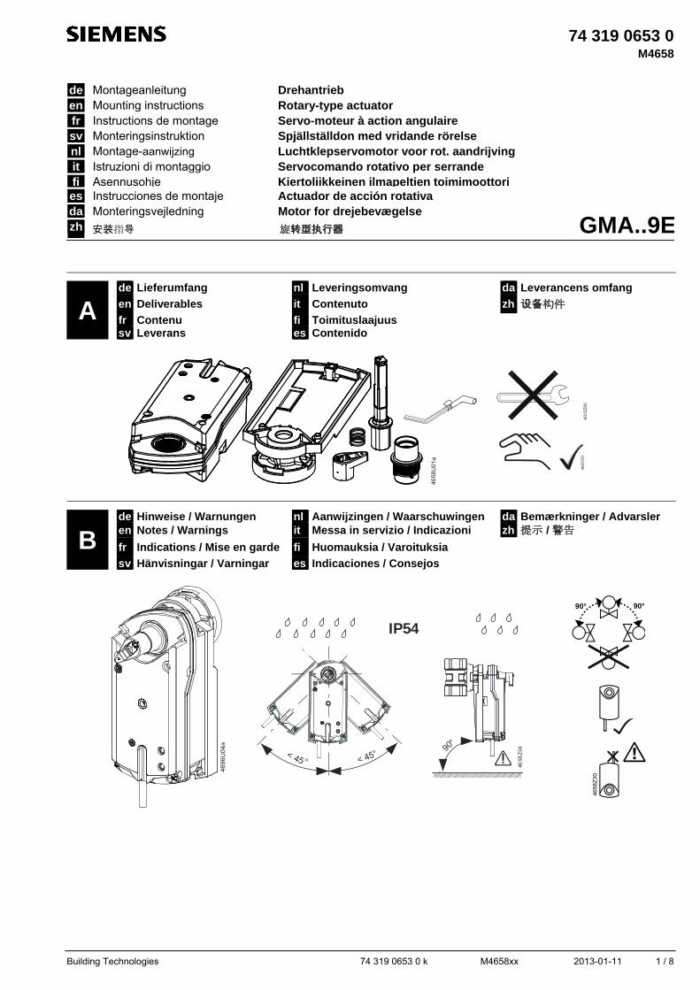
A de Lieferumfang nl Leveringsomvang da Leverancens omfang
en Deliverables it Contenuto zh 设备构件
fr Contenu fi Toimituslaajuus sv Leverans es Contenido
4658
U01
a
B de Hinweise / Warnungen nl Aanwijzingen / Waarschuwingen da Bemærkninger / Advarsler en Notes / Warnings it Messa in servizio / Indicazioni zh 提示 / 警告
fr Indications / Mise en garde fi Huomauksia / Varoituksia sv Hänvisningar / Varningar es Indicaciones / Consejos
469
6U0
4a
< 45° < 45°
IP54
90°
4658
Z04
90° 90°
de Montageanleitung Drehantrieb
GMA..9E
en Mounting instructions Rotary-type actuator fr Instructions de montage Servo-moteur à action angulaire sv Monteringsinstruktion Spjällställdon med vridande rörelse nl Montage-aanwijzing Luchtklepservomotor voor rot. aandrijving it Istruzioni di montaggio Servocomando rotativo per serrande fi Asennusohje Kiertoliikkeinen ilmapeltien toimimoottori es Instrucciones de montaje Actuador de acción rotativa da Monteringsvejledning Motor for drejebevægelse zh 安装指导 旋转型执行器
46
57Z
31
2 / 8 2013-01-11 M4658xx 74 319 0653 0 k Building Technologies
de sv fi Diese Anleitung ist beim Antrieb oder in der Anla-gendokumentation aufzubewahren!
Denna instruktion skall förvaras tillsammans med ställdonet eller anläggningsdokumentationen!
Tätä ohjetta tulee säilyttää toimimoottorin lähei-syydessä tai yhdessä laitosdokumenttien kanssa!
Dieses Symbol weist auf Gefahren und Masnah-men zum Schutz von Personen und Sachen hin:
Denna symbol gäller riskfaktorer samt åtgär-der för att undvika person- och materialskador.
Tämä symboli viittaa vaaraan ja toimenpitei-siin, joita tarvitaan henkilö- ja aineellisten vahinkojen välttämiseksi:
• Antriebe für AC 230 V dürfen nur durch autorisier-tes Personal angeschlossen werden.
• Die Anschlusskabel des Antriebs dürfen nicht im Wasser liegen.
• Das Anschlusskabel darf weder am Ventilkörper noch an den Rohren befestigt werden.
• Ställdon med AC 230 V får anslutas endast av behörig personal.
• Ställdonets anslutningskabel får inte ligga i vatten. • Fäst ej anslutningskabeln direkt på röret eller kul-
ventilen.
• Ainoastaan valtuutetut ammattihenkilöt saavat liittää 230 VAC:n toimimoottoreita.
• Toimimoottorin liitäntäkaapelit eivät saa kastua tai muuten altistua vedelle.
• Älä kiinnitä kytkentäjohtoa putkistoon tai pallo-venttiiliin
Gerät der Schutzklasse II (Schutzisolierung)
Apparat i isolerklass II (skyddsisolering)
Suojausluokan II laite (suoraerotus)
Gerät der Schutzklasse III (Schutzisolierung)
Apparat i isolerklass III (skyddsisolering)
Suojausluokan III laite (suojaerotus)
Achtung! Der Stellantrieb darf nicht geöffnet werden
OBS! Ställdonet får inte öppnas.
Huomio! Toimimoottoria ei saa avata.
Verdrahtung und Inbetriebnahme Siehe in den anlagenspezifischen Unterlagen und in der Basisdokumentation "Technische Grundlagen" CM2Z4614 zum Antrieb.
Elektrisk inkoppling och igångkörning Se anläggningsspecifika underlag och grund-läggande beskrivning “Handbok CM2Z4614” för ställdonet.
Johdotus ja käyttöönotto Katso laitoskohtaiset dokumentit ja toimimoottorin tekninen käsikirja CM2Z4614.
en nl esStore these instructions together with the actua-tor or with the plant documentation!
Deze handleiding moet bij de servomotor, of met de documentatie van de installatie worden bewaard!
Conserve estas instrucciones con el actuador o con la documentación de la instalación!
This symbol denotes dangers and measures to avoid personal injury and property damage:
Dit symbool wijst op gevaar en maatregelen ter bescherming van personen en materiaal:
Este símbolo denota peligro y medidas para evitar daños personales y de la propiedad:
• Only authorized personnel may connect actuators for AC 230 V.
• Do not expose the actuator's connecting cables to water or lay the cables in water.
• Do not attach the connecting cable to the piping or the ball valve.
• AC 230 V aandrijvingen mogen alleen door be-voegd personeel worden aangesloten.
• De aansluitkabel van de aandrijving mag niet in het water liggen.
• Aansluitkabel niet bevestigen aan afsluiterhuis of leidingen.
• Sólo el personal autorizado puede conectar los actuadores a 230 V CA.
• No exponer los cables de conexión del actuador al agua ni dejarlos en contacto con ésta.
• No sujetar los cables de conexión a la tubería o a la válvula de bola.
Device of protection class II (protective insulation)
Apparaat van beschermingsklasse II (be-schermings isolatie)
Equipo con tipo de protección II (aislamiento protegido)
Device of protection class III (protective insulation)
Apparaat van beschermingsklasse III (be-schermings isolatie)
Equipo con tipo de protección III (aislamien-to protegido)
Warning! Do not open the actuator.
Opgelet! De servomotor mag niet worden geopend.
Atención! el actuador no debe ser abierto.
Wiring and commissioning Refer to the actuator's commissioning instructions and document "Technical basics" CM2Z4614.
Bekabeling en inbedrijfstelling Raadpleeg de installatie-documentatie en de basis-documentatie “technische grondslagen” CM2Z4614 van de servomotor.
Cableado y puesta en marcha Ver la documentación técnica “Technical basics” CM2Z4614 del actuador.
fr it daCette instruction est à conserver avec le servo-moteur ou avec la documentation de l’installation!
Queste istruzioni devono essere conservate con la documentazione dell’impianto!
Opbevar denne vejledning sammen med moto-ren eller med anlægsdokumentationen!
Ce symbole signale un danger pour les per-sonnes et les biens et les mesures y-afférentes:
Questo simbolo indica – pericolo – il personale deve fare attenzione per evitare ferite o danni.
Dette symbol gør opmærksom på farer og forholdsregler til beskyttelse af personer og genstande:
• Le branchement des servomoteurs 230 V~ ne doit être effectué que par un personnel qualifié.
• Les câbles de raccordement du servomoteur ne doivent pas être en contact avec l'eau.
• Ne pas fixer le câble de raccordement du servomo-teur sur la tuyauterie ou sur la vanne.
• I collegamenti a 230 V CA . devono sempre essere eseguiti da personale autorizzati.
• Non esporre all‘acqua il cavo ed i collegamentii elettrici.
• Non attaccare il cavo di collegamento alle tubazioni o alla valvola a sfera.
• Motorer til AC 230 V må kun tilsluttes af autorise-rede personer.
• Motorens tilslutningskabler må ikke ligge i vand. • Forbindelseskablet må ikke fastgøres
til rørsystemet eller kugleventilen!
Classe d'isolation II (isolation de protection)
Apparecchi di protezione classe ii (protezio-ne isolamento)
Apparat i isoleringsklasse II (beskyttelsesi-solering)
Classe d'isolation III (isolation de protection)
Apparecchio di protezione classe III (prote-zione isolamento)
Apparat i isoleringsklasse III (beskyttelse-sisolering)
Attention! Le servo-moteur ne doit pas être ouvert.
Attenzione! Il servocomando non deve essere aperto.
OBS! Motoren må ikke åbnes.
Câblage et mise en service se référer à la documentation de l’installation et au manuel technique CM2Z4614 du servomoteur.
menti e messa in servizio Consultare la documentazione per l’installazione e il foglio tecnico (CM2Z4614) del servocomando.
Eltilslutning og idriftsættelse Se den anlægsspecifikke dokumentation samt basisdokumentationen “Tekniske principper” CM2Z4614 for motoren.
zh
请将此安装指导文件与驱动器或现场文件保存在一起。
此符号代表危险和须要採取措施以免对人及财產生损害: • 只有被授权的工程人员才可进行230V交流电压的电气安装。 • 不要将已连接电线的驱动器暴露在水中及将电线安放在水中。
• 请勿连接电缆至管道或球阀
设备安全等级II (绝缘保护)
设备安全等级 III (绝缘保护)
注意 ! 请不要打开驱动器
驱动器接线和調试 请察看调试指导和驱动器技术资料CM2Z4614.
Building Technologies 74 319 0653 0 k M4658xx 2013-01-11 3 / 8
465
8Z34
1
2
3 46
58 Z
15
3
2
1
465
8Z35
46
58Z
32
45°
46
58Z
19
12
46
58J
0 1a
1
2
3
C
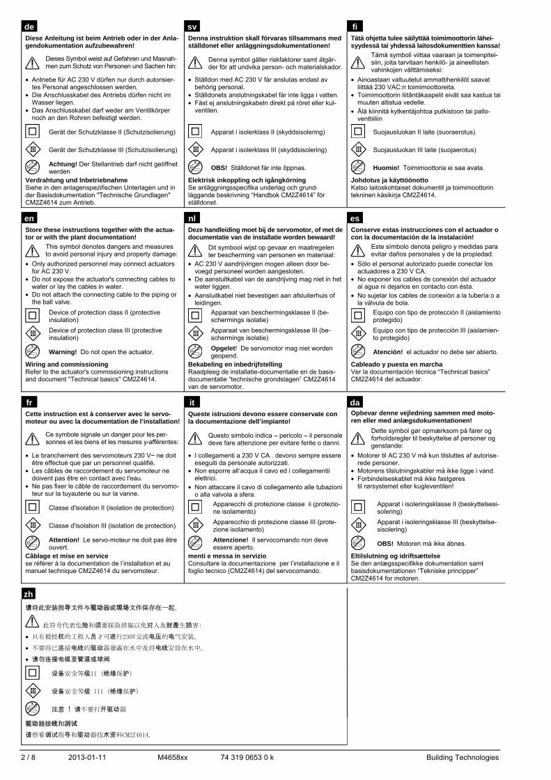
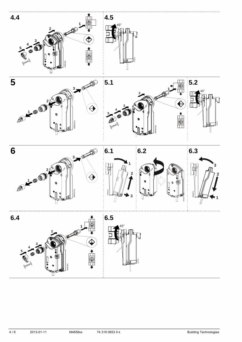
de Montage auf Kugelhahn nl Montage op de Kogelafsluiter da Montering på kulventil
en Ball valve Mounting it Montaggio sull’valvoia a sfera zh 裝配在球閥閥體上
fr Montage sur vanne à boisseau sphérique
fi Asennus palloventtiiliin
sv Montera ställdonet på kulventilen es Montaje sobre el válvula de bola
1 GMA..9E + VAI61.. / VBI61.. 2 … 6.5
GMA..9E + VAI60.. / VBI60.. 7 … 9.5
2
3 3.1
4 4.1 4.2 4.3
469
5Z0
4
NCNormallyClosed
NONormallyOpen
3
4
5
6
NCNormallyClosed
NONormallyOpen
4 / 8 2013-01-11 M4658xx 74 319 0653 0 k Building Technologies
45°
465
8Z3
6
465 8
Z15
3
2
1
45°
4658
Z36
45°
4658
Z36
4658
J 02
1
Click
2
34
5
4658
Z35
4 658
J04
Click
2
34
5
1
46
58J
0 1a
1
2
3
46
58J
0 1a
1
2
34
658 J
03 aClick
2
34
5
1
4.4 4.5
5 5.1 5.2
6 6.1 6.2 6.3
6.4 6.5
465 8
Z3
4
1
2
3
Building Technologies 74 319 0653 0 k M4658xx 2013-01-11 5 / 8
465
8Z34
1
2
3
4658
Z35
4658
Z35
45°
4658
Z36
46
58J
0 1a
1
2
3
465 8
Z15
3
2
1
4658
J 02
1
Click
2
34
5
46
58J
0 1a
1
2
3
465
8Z34
1
2
3
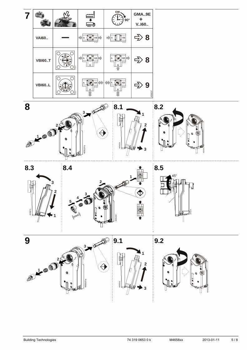
7
8 8.1 8.2
8.3 8.4 8.5
9 9.1 9.2
A AB
4213Z01
A AB
4213Z02
B
A AB
4213Z03
A
B
A AB
4213Z04
B
A AB
4213Z05
B
A AB
4213Z06
VAI60..
VBI60..L
VBI60..T
cw
90°
GMA..9E
V..I60..
A AB
B
4213
Z12
A AB
B
4213
Z13
+
8
9
8
46
58Z
37
6 / 8 2013-01-11 M4658xx 74 319 0653 0 k Building Technologies
4658
Z15
3
2
1
45°
4658
Z36
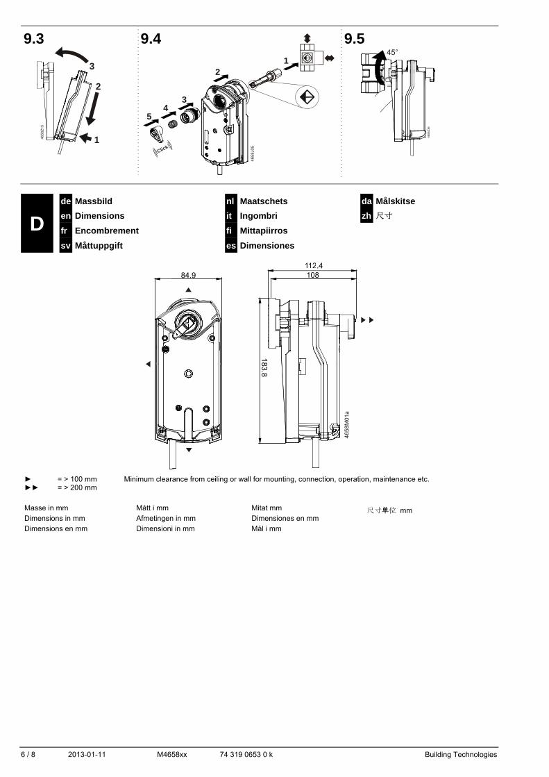
9.3 9.4 9.5
D de Massbild nl Maatschets da Målskitse
en Dimensions it Ingombri zh 尺寸
fr Encombrement fi Mittapiirros sv Måttuppgift es Dimensiones
4658
M01
a
► = > 100 mm Minimum clearance from ceiling or wall for mounting, connection, operation, maintenance etc. ►► = > 200 mm
Masse in mm
Dimensions in mm
Dimensions en mm
Mått i mm
Afmetingen in mm
Dimensioni in mm
Mitat mm
Dimensiones en mm
Mål i mm
尺寸单位 mm
4658J0
5
1
Click
2
34
5
Building Technologies 74 319 0653 0 k M4658xx 2013-01-11 7 / 8
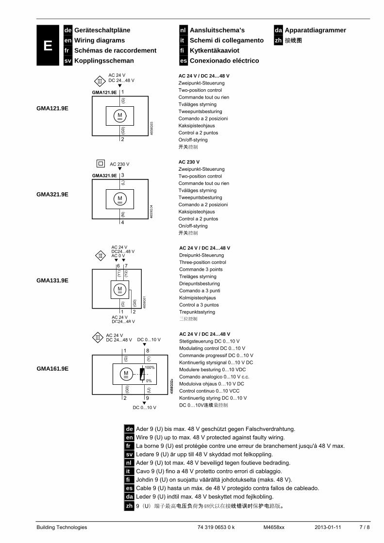
E de Geräteschaltpläne nl Aansluitschema’s da Apparatdiagrammer
en Wiring diagrams it Schemi di collegamento zh 接线图 fr Schémas de raccordement fi Kytkentäkaaviot sv Kopplingsscheman es Conexionado eléctrico
GMA121.9E
(G)
(G0
)
2
1
M
AC 24 VDC 24...48 V
AC 24 V / DC 24…48 V
Zweipunkt-Steuerung
Two-position control
Commande tout ou rien
Tvåläges styrning
Tweepuntsbesturing
Comando a 2 posizioni
Kaksipisteohjaus
Control a 2 puntos
On/off-styring
开关控制
GMA321.9E
(L)
AC 230 V
(N)
4
3
M
AC 230 V
Zweipunkt-Steuerung
Two-position control
Commande tout ou rien
Tvåläges styrning
Tweepuntsbesturing
Comando a 2 posizioni
Kaksipisteohjaus
Control a 2 puntos
On/off-styring
开关控制
GMA131.9E
(G)
1
76
M
(G0)
2
AC 24 VDC24...48 VAC 0 V
AC 24 VDC24...48 V
AC 24 V / DC 24…48 V
Dreipunkt-Steuerung
Three-position control
Commande 3 points
Treläges styrning
Driepuntsbesturing
Comando a 3 punti
Kolmipisteohjaus
Control a 3 puntos
Trepunktsstyring
三位控制
GMA161.9E 100%
0%
DC 0...10 V
DC 0...10 V
(G0
)
(U)
2 9
1 8
AC 24 VDC 24...48 V
M
AC 24 V / DC 24…48 V
Stetigsteuerung DC 0...10 V
Modulating control DC 0...10 V
Commande progressif DC 0...10 V
Kontinuerlig styrsignal 0...10 V DC
Modulere besturing 0...10 VDC
Comando analogico 0...10 V c.c.
Moduloiva ohjaus 0…10 V DC
Control continuo 0...10 VCC
Kontinuerlig styring DC 0...10 V
DC 0…10V连续量控制
de Ader 9 (U) bis max. 48 V geschützt gegen Falschverdrahtung. en Wire 9 (U) up to max. 48 V protected against faulty wiring.
fr La borne 9 (U) est protégée contre une erreur de branchement jusqu'à 48 V max.
sv Ledare 9 (U) är upp till 48 V skyddad mot felkoppling.
nl Ader 9 (U) tot max. 48 V beveiligd tegen foutieve bedrading.
it Cavo 9 (U) fino a 48 V protetto contro errori di cablaggio.
fi Johdin 9 (U) on suojattu väärältä johdotukselta (maks. 48 V).
es Cable 9 (U) hasta un máx. de 48 V protegido contra fallos de cableado.
da Leder 9 (U) indtil max. 48 V beskyttet mod fejlkobling.
zh 9(U)端子最高电压负荷为48伏以在接线错误时保护电路版。
8 / 8 2013-01-11 M4658xx 74 319 0653 0 k Building Technologies
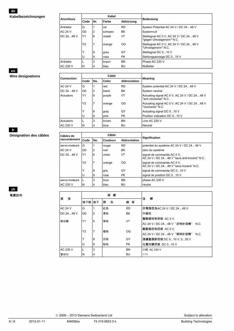
de
Kabelbezeichnungen
Anschluss
Kabel Bedeutung
Code Nr. Farbe Abkürzung
Antriebe G 1 rot RD System Potential AC 24 V / DC 24…48 V
AC 24 V G0 2 schwarz BK Systemnull
DC 24…48 V Y1 6 violett VT Stellsignal AC 0 V, AC 24 V / DC 24…48 V "gegen Uhrzeigersinn" N.C.
Y2 7 orange OG Stellsignal AC 0 V, AC 24 V / DC 24…48 V "Uhrzeigersinn" N.C.
Y 8 grau GY Stellsignal DC 0...10 V
U 9 rosa PK Stellungsanzeige DC 0...10 V
Antriebe L 3 braun BN Phase AC 230 V
AC 230 V N 4 blau BU Nullleiter
en
Wire designations Connection
Cable Meaning
Code No. Color Abbreviation
AC 24 V G 1 red RD System potential AC 24 V / DC 24…48 V
DC 24…48 V G0 2 black BK System neutral
Actuators Y1 6 purple VT Actuating signal AC 0 V, AC 24 V / DC 24…48 V "anti clockwise" N.C.
Y2 7 orange OG Actuating signal AC 0 V, AC 24 V / DC 24…48 V "clockwise" N.C.
Y 8 gray GY Actuating signal DC 0...10 V
U 9 pink PK Position indication DC 0...10 V
Actuators L 3 brown BN Line AC 230 V
AC 230 V N 4 blue BU Neutral
fr
Désignation des câbles Câbles de raccordement
Câble Signification
Code No. Couleurs Abbreviation
servo-moteurs G 1 rouge RD potentiel du système AC 24 V / DC 24…48 V
AC 24 V G0 2 noir BK zéro du système
DC 24…48 V Y1 6 violet VT signal de commande AC 0 V, AC 24 V / DC 24…48 V "sens anti-horaire" N.C.
Y2 7 orange OG signal de commande AC 0 V, AC 24 V / DC 24…48 V "sens horaire" N.C.
Y 8 gris GY signal de commande DC 0...10 V
U 9 rose PK signal de position DC 0...10 V
servo-moteurs L 3 brun BN phase AC 230 V
AC 230 V N 4 bleu BU neutre
zh
電纜說明 連 接
線 纜 注 解
端子號 端子 顏 色 縮 寫
AC 24 V G 1 紅色 RD 供電類型為AC 24 V / DC 24…48 V
DC 24…48 V G0 2 黑色 BK 中線性
驱动器 Y1 6 紫色 VT 驅動器控制信號 AC 0 V,
AC 24 V / DC 24…48 V "逆時針旋轉" N.C.
Y2 7 橙色 OG
驅動器控制信號 AC 0 V,
AC 24 V / DC 24…48 V "順時針旋轉" N.C.
Y 8 灰色 GY 連續量調節信號 DC 0...10 V, 0...35 V
U 9 粉色 PK 位置回饋信號 DC 0...10 V
AC 230 V L 3 BN 相线 AC 230 V
驱动器 N 4 BU 中性
2009 – 2013 Siemens Switzerland Ltd Subject to alteration