Embed Size (px)
Citation preview
7/31/2019 8-JPE 09-40
http://slidepdf.com/reader/full/8-jpe-09-40 1/11
892 Journal of Power Electronics, Vol. 9, No. 6, November 2009
JPE 9-6-8
Dynamic Coordination Strategies between HVDC and STATCOM
Chan-Ki Kim†, Vijay Sood
*, and Seok-Jin Lee
**
†KEPRI (Korea Electric Power Research Institute), Korea*University of Ontario Institute of Technology (UOIT), Canada
**KEPCO (Korea Electric Power Corporation), Korea
ABSTRACT
This paper deals with the dynamic voltage control problem at the inverter end of a HVDC link when connected to a
weak AC system which has the potential for harmonic instability and commutation failures. The dynamic voltage control
problem is tackled with a STATCOM (Static Compensator), which not only provides a rapid recovery from harmonic
instability and commutation failures but also offers a lower cost filter design for HVDC systems. PSCAD/EMTDC
simulations are presented to validate the proposed topology and to demonstrate its robust performance.
Keywords: HVDC transmission, STATCOM
1. Introduction
Line commutated HVDC converters inherently
consume large amounts of reactive power; typically, the
reactive power demands of these converters are 50-60% of
the DC power being transferred. For the design and safe
operation of HVDC thyristor converters, there are special
concerns when connecting to weak AC systems. These
concerns include high temporary over voltages (TOVs),
low frequency resonances, risk of voltage instability,
harmonic instability, long fault recovery times and
increased risk of commutation failure. Many of these
concerns are closely related to AC voltage regulation at
the converter bus. Some possible means of voltage
regulation are the Synchronous Compensator (SC) (now
virtually obsolete), the Static Var Compensator (SVC) and
now the latest method, employing a Static Synchronous
Compensator (STATCOM). The STATCOM option is
likely to be employed with variable speed wind generator
systems which will use voltage source converter (VSC)
technology to connect to the grid.
Until now, HVDC systems and their associated reactive
compensators were mostly operated and controlled
independently. The interactions between HVDC system
filters and reactive power compensator were largely
considered under steady state conditions only. If the
control between a HVDC system and its reactive power
compensator can be actively coordinated, the performance
of the HVDC will be improved in the transient state.
This will also result in improved dynamic performance.
With the industry increasingly leaning or being forced
towards the integration of HVDC systems to weaker AC
networks, the transient performance of such systems is of
Manuscript received Mar. 31, 2009; revised Sept. 23, 2009†Corresponding Author: [email protected] Tel: +82-42-865-5837, Fax: +82-42-865-5844, KEPRI
*University of Ontario Institute of Technology, Canada** KEPCO (Korea Electric Power Corporation), Korea
7/31/2019 8-JPE 09-40
http://slidepdf.com/reader/full/8-jpe-09-40 2/11
Dynamic Coordination Strategies between HVDC and STATCOM 893
vital importance. Earlier research [1] has indicated that the
combination of SVCs with SCs provided much faster
system response than SCs or SVCs alone. Other research[2]
proposed a hybrid HVDC system coordinated with a
STATCOM. A more modern topology, which considers
the characteristics of the line-commutated HVDC with a
STATCOM at the inverter end, is proposed in this paper.
The proposed system consists of a black start function and
a HVDC-STATCOM coordination control scheme.
Furthermore, this paper investigates the advantages of the
new STATCOM based system from the point of view of
the cost reduction of the HVDC link filter design,
recovery from commutation failures and overvoltage
control as well as the dynamics of recovery from various
system disturbances including undervoltage events. The
main objectives of the proposed topology are (a) to
dynamically control AC voltage at the inverter end of
HVDC links, and (b) to achieve coordination control with
HVDC systems.
The paper is structured as follows: first, the combined
HVDC and STATCOM test system, along with the control
strategies employed and the choice of the coordinating
signal, are described in section 2: second, the impact
studies of the STATCOM are presented in section 3: third,
a number of dynamic simulation studies performed with aEMTDC/PSCAD are discussed. Finally, some concluding
remarks are made.
2. HVDC- STATCOM System
2.1 Overall Test System
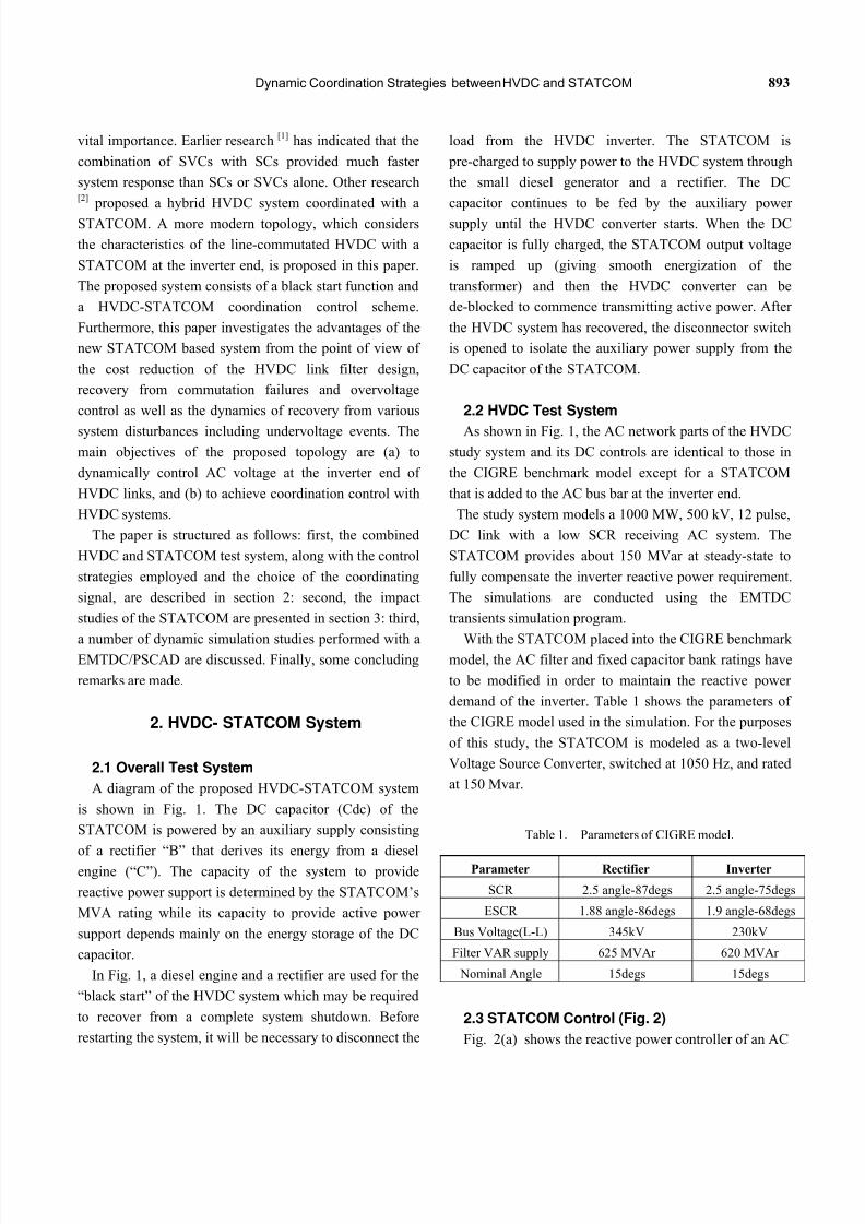
A diagram of the proposed HVDC-STATCOM system
is shown in Fig. 1. The DC capacitor (Cdc) of the
STATCOM is powered by an auxiliary supply consisting
of a rectifier “B” that derives its energy from a dieselengine (“C”). The capacity of the system to provide
reactive power support is determined by the STATCOM’s
MVA rating while its capacity to provide active power
support depends mainly on the energy storage of the DC
capacitor.
In Fig. 1, a diesel engine and a rectifier are used for the
“black start” of the HVDC system which may be required
to recover from a complete system shutdown. Before
restarting the system, it will be necessary to disconnect the
load from the HVDC inverter. The STATCOM is
pre-charged to supply power to the HVDC system through
the small diesel generator and a rectifier. The DC
capacitor continues to be fed by the auxiliary power
supply until the HVDC converter starts. When the DC
capacitor is fully charged, the STATCOM output voltage
is ramped up (giving smooth energization of the
transformer) and then the HVDC converter can be
de-blocked to commence transmitting active power. After
the HVDC system has recovered, the disconnector switch
is opened to isolate the auxiliary power supply from the
DC capacitor of the STATCOM.
2.2 HVDC Test System
As shown in Fig. 1, the AC network parts of the HVDC
study system and its DC controls are identical to those in
the CIGRE benchmark model except for a STATCOM
that is added to the AC bus bar at the inverter end.
The study system models a 1000 MW, 500 kV, 12 pulse,
DC link with a low SCR receiving AC system. The
STATCOM provides about 150 MVar at steady-state to
fully compensate the inverter reactive power requirement.
The simulations are conducted using the EMTDC
transients simulation program.
With the STATCOM placed into the CIGRE benchmark model, the AC filter and fixed capacitor bank ratings have
to be modified in order to maintain the reactive power
demand of the inverter. Table 1 shows the parameters of
the CIGRE model used in the simulation. For the purposes
of this study, the STATCOM is modeled as a two-level
Voltage Source Converter, switched at 1050 Hz, and rated
at 150 Mvar.
Table 1. Parameters of CIGRE model.
Parameter Rectifier Inverter
SCR 2.5 angle-87degs 2.5 angle-75degs
ESCR 1.88 angle-86degs 1.9 angle-68degs
Bus Voltage(L-L) 345kV 230kV
Filter VAR supply 625 MVAr 620 MVAr
Nominal Angle 15degs 15degs
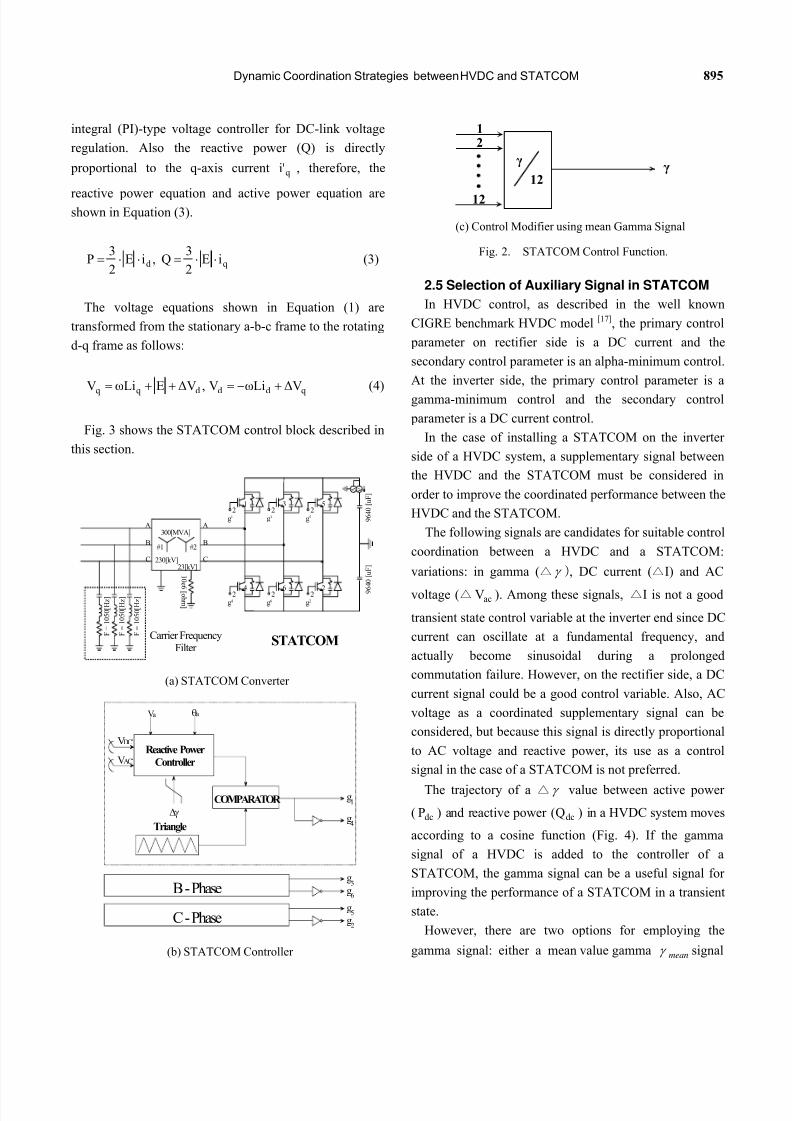
2.3 STATCOM Control (Fig. 2)
Fig. 2(a) shows the reactive power controller of an AC
7/31/2019 8-JPE 09-40
http://slidepdf.com/reader/full/8-jpe-09-40 3/11
894 Journal of Power Electronics, Vol. 9, No. 6, November 2009
Fig. 1. Configuration of Proposed STATCOM System.
network. Fig. 2(b) shows the auxiliary control signal
which modifies the control signal of the STATCOM based
on the mean value of gamma (discussed later) at the
inverter end of the HVDC system.
The AC voltage variations at the inverter bus of the
HVDC system are directly related to the gamma value of
the inverter. Hence, the gamma signal can be added to the
voltage reference of the STATCOM to enhance system performance. In this way, it is possible to control the
gamma to a specific range even during fast transients.
2.4 STATCOM Modeling
The terminal voltage and current of the STATCOM, at
the point of connection, can be modeled by a vector
representation. This vector representation is extended by a
d-q model which leads to the definitions of instantaneous
reactive current and active current. The voltage equations
in the stationary a-b-c frame are:
c b
c b b
baa
a Vdt
diLe,V
dt
diLe,V
dt
diLe (1)
Also, the voltage equations in the rotating d-q frame
and the input voltages in the rotating d-q frame are shown
in Equation (2).
qd
q
qdd
d VωLidt
diLe,ωLi
dt
diLe
0e,Ee dd (2)
Since the active power (P) supplied from the input is
directly proportional to the d-axis current , the d-axis
reference current is generated from a proportional and
di
di'
7/31/2019 8-JPE 09-40
http://slidepdf.com/reader/full/8-jpe-09-40 4/11
Dynamic Coordination Strategies between HVDC and STATCOM 895
integral (PI)-type voltage controller for DC-link voltage
regulation. Also the reactive power (Q) is directly
proportional to the q-axis current , therefore, the
reactive power equation and active power equation areshown in Equation (3).
qi'
qd iE2
3Q,iE
2
3P (3)
The voltage equations shown in Equation (1) are
transformed from the stationary a-b-c frame to the rotating
d-q frame as follows:
qdddqqΔ
Vω
LiV,Δ
VEω
LiV (4)
Fig. 3 shows the STATCOM control block described in
this section.
300[MVA]
230[kV]
#1 #2
23[kV]
A
B
C
23
g3
21
g1
25
g5
2 6
g6
2 4
g4
2 2
g2
A
B
C
V A
1 0 e 6 [ oh m ]
F = 1 0 5 0 [ H z ]
F = 1 0 5 0 [ H z ]
F = 1 0 5 0 [ H z ]
9 6 4 0 [ u F ]
9 6
4 0 [ u F ]
STATCOMCarrier FrequencyFilter
(a) STATCOM Converter
Reactive Power
Controller
VDC*
VAC*
Va a
COMPARATOR
B - Phase
C - Phase
Triangle
g1
g4
g3
g6
g5
g2
(b) STATCOM Controller
12
12
12
γγ
(c) Control Modifier using mean Gamma Signal
Fig. 2. STATCOM Control Function.
2.5 Selection of Auxiliary Signal in STATCOM
In HVDC control, as described in the well known
CIGRE benchmark HVDC model [17], the primary control
parameter on rectifier side is a DC current and the
secondary control parameter is an alpha-minimum control.
At the inverter side, the primary control parameter is a
gamma-minimum control and the secondary control
parameter is a DC current control.
In the case of installing a STATCOM on the inverter
side of a HVDC system, a supplementary signal between
the HVDC and the STATCOM must be considered in
order to improve the coordinated performance between the
HVDC and the STATCOM.
The following signals are candidates for suitable control
coordination between a HVDC and a STATCOM:
variations: in gamma (△ ), DC current (△I) and AC
voltage (△ ). Among these signals, △I is not a good
transient state control variable at the inverter end since DC
current can oscillate at a fundamental frequency, and
actually become sinusoidal during a prolonged
commutation failure. However, on the rectifier side, a DC
current signal could be a good control variable. Also, AC
voltage as a coordinated supplementary signal can be
considered, but because this signal is directly proportional
to AC voltage and reactive power, its use as a control
signal in the case of a STATCOM is not preferred.
acV
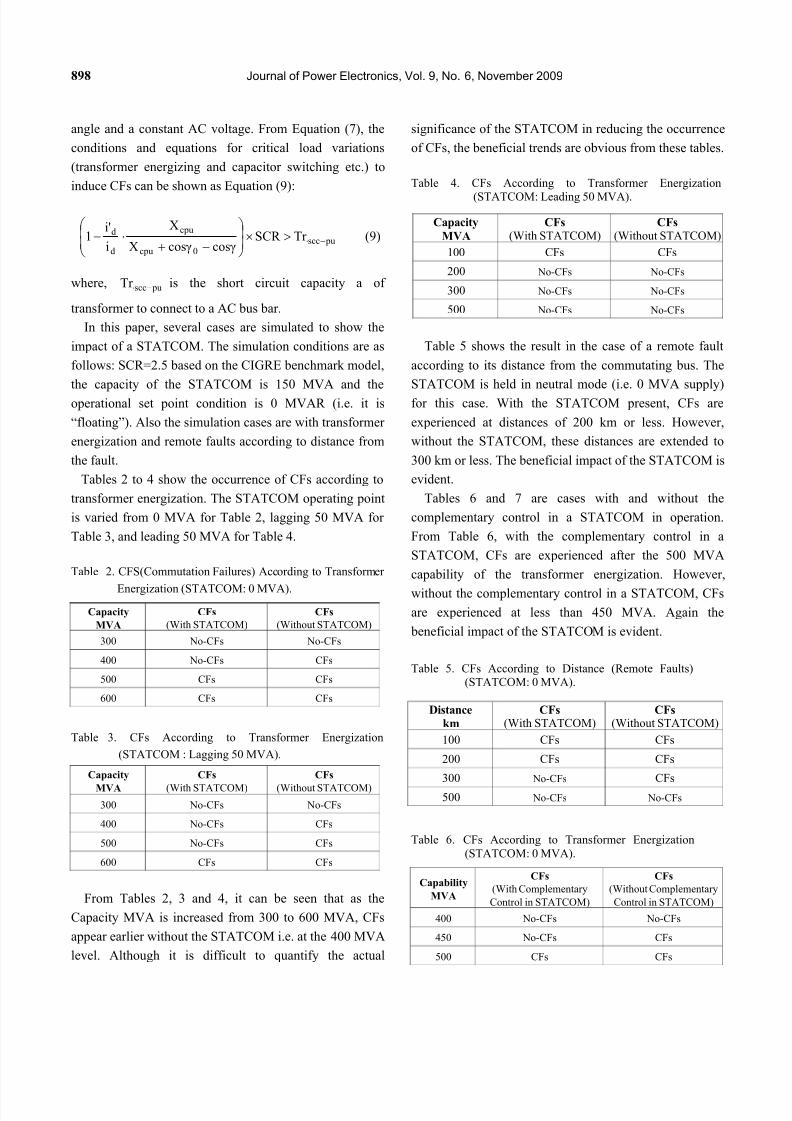
The trajectory of a △ value between active power
( ) and reactive power ( ) in a HVDC system moves
according to a cosine function (Fig. 4). If the gamma
signal of a HVDC is added to the controller of a
STATCOM, the gamma signal can be a useful signal for
improving the performance of a STATCOM in a transient
state.
dcP dcQ
However, there are two options for employing the
gamma signal: either a mean value gamma signalmean
7/31/2019 8-JPE 09-40
http://slidepdf.com/reader/full/8-jpe-09-40 5/11
896 Journal of Power Electronics, Vol. 9, No. 6, November 2009
Vdc*
Vdc
+
-
Voltagecontroller
+
id*
-
iLd
ifd*
+
-
Currentcontroller
Lifd
+
E
+
Lifq
vd
+
+
Vd
+-
iLq
ifq*
+-
Currentcontroller
+
vq
VqVac*
Vac
+-
Voltagecontroller iq
*
K
γ ref γmeas
+ -
+ -
Fig. 3. STATCOM Controller Model.
or a minimum value gamma signal. The signal
is more relevant for improving performance against a
commutation failure, but the response time is inherently
slower (when compared to the derivation of the ) due
to the computation algorithm. On the other hand, the
min min
mean
mean is less relevant against commutation failure, but
the response time is fast. Furthermore, the mean is
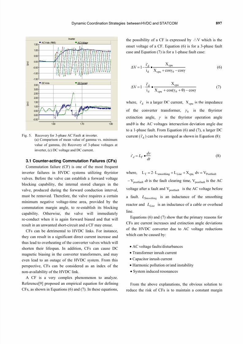
always higher than the value. This comparison isshown in Fig. 5(a) for the recovery of the system
following a 3-phase fault at the inverter. Fig. 5(b) shows
the recovery of the 3-phase AC voltages, and Fig. 5(c)
shows the recovery of the corresponding DC current
and DC voltage .
min
dcI dcV
Due to the relative speed of the response characteristics,
a mean signal is selected as the coordinated supplementary
signal of the STATCOM. The supplementary signal of the
STATCOM is as follows:
]γK[γΔγ meas.ref.
(5)
A signal which represents gamma variation, as shown in
Equation (5), is added to the STATCOM controller.
0Pdc
Operating pointDecrease
Increase
γ Value
Qdc
3. Impact of the STATCOM
The impact of the STATCOM is felt upon the following
system aspects:
Rectifier : Graphs
1.60 1.70 1.80
0.00
0.50
1.00
1.50
2.00
2.503.00
3.50
4.00
y
Mean Min
Fig. 4. Trajectory between active power and reactive power in
HVDC.
7/31/2019 8-JPE 09-40
http://slidepdf.com/reader/full/8-jpe-09-40 6/11
Dynamic Coordination Strategies between HVDC and STATCOM 897
Inverter
1.60 1.70 1.80
-1.50
-1.00
-0.50
0.00
0.50
1.00
1.50
( p u )
AC Volts (RMS) AC Voltage
-0.50
0.00
0.50
1.00
1.50
2.00
2.50
3.00
3.50
( p u )
DCVolts DCCurrent
Fig. 5. Recovery for 3-phase AC Fault at inverter.(a) Comparison of mean value of gamma vs. minimum
value of gamma, (b) Recovery of 3-phase voltages at
inverter, (c) DC voltage and DC current.
3.1 Counter-acting Commutation Failures (CFs)
Commutation failure (CF) is one of the most frequent
inverter failures in HVDC systems utilizing thyristor
valves. Before the valve can establish a forward voltage
blocking capability, the internal stored charges in the
valve, produced during the forward conduction interval,
must be removed. Therefore, the valve requires a certain
minimum negative voltage-time area, provided by the
commutation margin angle, to re-establish its blocking
capability. Otherwise, the valve will immediately
re-conduct when it is again forward biased and that will
result in an unwanted short-circuit and a CF may ensue.
CFs can be detrimental to HVDC links. For instance,
they can result in a significant direct current increase and
thus lead to overheating of the converter valves which will
shorten their lifespan. In addition, CFs can cause DC
magnetic biasing in the converter transformers, and may
even lead to an outage of the HVDC system. From this
perspective, CFs can be considered as an index of the
non-availability of the HVDC link.
A CF is a very complex phenomenon to analyze.
Reference[9] proposed an empirical equation for defining
CFs, as shown in Equations (6) and (7). In these equations,
the possibility of a CF is expressed by △V which is the
onset voltage of a CF. Equation (6) is for a 3-phase fault
case and Equation (7) is for a 1-phase fault case:
cosγcosγX
X
i
i'1ΔV
0cpu
cpu
d
d
(6)
cosγθ)cos(γX
X
i
i'1ΔV
0cpu
cpu
d
d
(7)
where, is a larger DC current, is the impedance
of the converter transformer,
di' cpuX
0 is the thyristor
extinction angle, is the thyristor operation angle
and is the AC voltages intersection deviation angle due
to a 1-phase fault. From Equation (6) and (7), a larger DC
current ( ) can be re-arranged as shown in Equation (8):
θ
di'
dt
dv Li T d ' (8)
where, Postfaultcpu,LinesmoothingT VdvXLL2L
postfaultV dt
L
is the fault clearing time, is the AC
voltage after a fault and is the AC voltage before
a fault. is an inductance of the smoothing
reactor and is an inductance of a cable or overhead
line.
postfaultV
postfaultV
Smoothing
Line
L
Equations (6) and (7) show that the primary reasons for
CFs are current increases and extinction angle deviations
of the HVDC converter due to AC voltage reductions
which can be caused by:
AC voltage faults/disturbances
Transformer inrush current
Capacitor inrush current
Harmonic pollution or/and instability
System induced resonances
From the above explanations, the obvious solution to
reduce the risk of CFs is to maintain a constant margin
7/31/2019 8-JPE 09-40
http://slidepdf.com/reader/full/8-jpe-09-40 7/11
898 Journal of Power Electronics, Vol. 9, No. 6, November 2009
angle and a constant AC voltage. From Equation (7), the
conditions and equations for critical load variations
(transformer energizing and capacitor switching etc.) to
induce CFs can be shown as Equation (9):
puscc0cpu
cpu
d
d Tr SCR cosγcosγX
X
i
i'1
(9)
where, is the short circuit capacity a of
transformer to connect to a AC bus bar.
pusccTr
In this paper, several cases are simulated to show the
impact of a STATCOM. The simulation conditions are as
follows: SCR=2.5 based on the CIGRE benchmark model,
the capacity of the STATCOM is 150 MVA and the
operational set point condition is 0 MVAR (i.e. it is
“floating”). Also the simulation cases are with transformer
energization and remote faults according to distance from
the fault.
Tables 2 to 4 show the occurrence of CFs according to
transformer energization. The STATCOM operating point
is varied from 0 MVA for Table 2, lagging 50 MVA for
Table 3, and leading 50 MVA for Table 4.
Table 2. CFS(Commutation Failures) According to Transformer
Energization (STATCOM: 0 MVA).
Table 3. CFs According to Transformer Energization
(STATCOM : Lagging 50 MVA).
From Tables 2, 3 and 4, it can be seen that as the
Capacity MVA is increased from 300 to 600 MVA, CFs
appear earlier without the STATCOM i.e. at the 400 MVA
level. Although it is difficult to quantify the actual
significance of the STATCOM in reducing the occurrence
of CFs, the beneficial trends are obvious from these tables.
Table 4. CFs According to Transformer Energization
(STATCOM: Leading 50 MVA).
Table 5 shows the result in the case of a remote fault
according to its distance from the commutating bus. The
STATCOM is held in neutral mode (i.e. 0 MVA supply)
for this case. With the STATCOM present, CFs are
experienced at distances of 200 km or less. However,
without the STATCOM, these distances are extended to
300 km or less. The beneficial impact of the STATCOM is
evident.
Tables 6 and 7 are cases with and without the
complementary control in a STATCOM in operation.
From Table 6, with the complementary control in a
STATCOM, CFs are experienced after the 500 MVA
capability of the transformer energization. However,
without the complementary control in a STATCOM, CFs
are experienced at less than 450 MVA. Again the
beneficial impact of the STATCOM is evident.
Table 5. CFs According to Distance (Remote Faults)(STATCOM: 0 MVA).
Table 6. CFs According to Transformer Energization
(STATCOM: 0 MVA).
Capacity
MVA
CFs
(With STATCOM)
CFs
(Without STATCOM)
300 No-CFs No-CFs
400 No-CFs CFs
500 CFs CFs
600 CFs CFs
Capacity
MVA
CFs
(With STATCOM)
CFs
(Without STATCOM)
300 No-CFs No-CFs
400 No-CFs CFs
500 No-CFs CFs
600 CFs CFs
Capacity
MVA
CFs(With STATCOM)
CFs(Without STATCOM)
100 CFs CFs
200 No-CFs No-CFs
300 No-CFs No-CFs
500 No-CFs No-CFs
Distance
km
CFs(With STATCOM)
CFs(Without STATCOM)
100 CFs CFs
200 CFs CFs
300 No-CFs CFs
500 No-CFs No-CFs
Capability
MVA
CFs
(With Complementary
Control in STATCOM)
CFs
(Without Complementary
Control in STATCOM)
400 No-CFs No-CFs
450 No-CFs CFs
500 CFs CFs
7/31/2019 8-JPE 09-40
http://slidepdf.com/reader/full/8-jpe-09-40 8/11
Dynamic Coordination Strategies between HVDC and STATCOM 899
As shown in Table 7, the incidences of CFs in relation
to the distance to a remote fault are investigated. With the
STATCOM complementary control in operation, the
distance to a fault can be extended beyond 250 kms
without causing CFs. However, without the STATCOM,
this distance has to be increased to beyond 250 kms.
Again the benefits of the STATCOM are evident.
Table 7. CFs According to Distance (Remote Faults)
(STATCOM: 0 MVA).
Distance
km
CFs
(With Complementary
Control in STATCOM)
CFs
(Without Complementary
Control in STATCOM)
200 CFs CFs
250 No-CFs CFs
300 No-CFs No-CFs
3.2 Complementing HVDC Filter Unit Size
Typically, the filter bank size in a HVDC system is
determined to obtain a net voltage step of 5% under the
minimum short circuit level condition. However, if the
voltage step can be controlled, the filter unit size can be
larger and, consequently, the number of filter banks can be
reduced. Such characteristics can also reduced the amount
of filter switching and enhance system reliability.
3.3 Robustness against Harmonic Pollution
From Equations (6) and (7), the main causes of CFs are
DC over-currents and AC voltage reduction. AC
harmonics are another major factor which can cause CFs
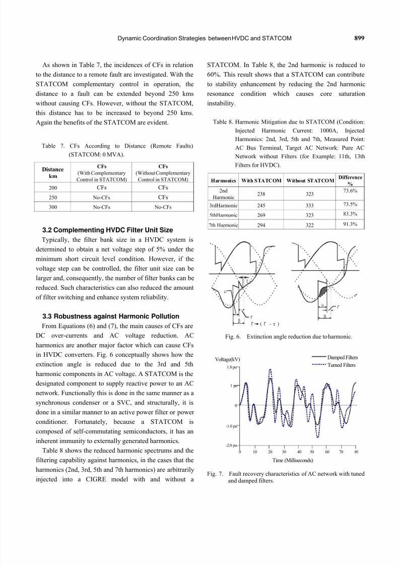
in HVDC converters. Fig. 6 conceptually shows how the
extinction angle is reduced due to the 3rd and 5th
harmonic components in AC voltage. A STATCOM is the
designated component to supply reactive power to an AC
network. Functionally this is done in the same manner as asynchronous condenser or a SVC, and structurally, it is
done in a similar manner to an active power filter or power
conditioner. Fortunately, because a STATCOM is
composed of self-commutating semiconductors, it has an
inherent immunity to externally generated harmonics.
Table 8 shows the reduced harmonic spectrums and the
filtering capability against harmonics, in the cases that the
harmonics (2nd, 3rd, 5th and 7th harmonics) are arbitrarily
injected into a CIGRE model with and without a
STATCOM. In Table 8, the 2nd harmonic is reduced to
60%. This result shows that a STATCOM can contribute
to stability enhancement by reducing the 2nd harmonic
resonance condition which causes core saturation
instability.
Table 8. Harmonic Mitigation due to STATCOM (Condition:
Injected Harmonic Current: 1000A, Injected
Harmonics: 2nd, 3rd, 5th and 7th, Measured Point:
AC Bus Terminal, Target AC Network: Pure AC
Network without Filters (for Example: 11th, 13th
Filters for HVDC).
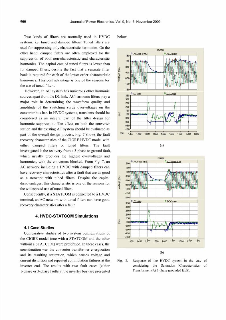
Fig. 6. Extinction angle reduction due to harmonic.
Fig. 7. Fault recovery characteristics of AC network with tunedand damped filters.
Harmonics With STATCOM Without STATCOMDifference
%
2nd
Harmonic238 323
73.6%
3rdHarmonic 245 333 73.5%
5thHarmonic 269 323 83.3%
7th Harmonic 294 322 91.3%
β
τ
Γ ( Γ - τ )
μ
Γ β
μΓ
-2.0 pu
-1.0 pu
0
1 pu
1.8 pu
Voltage(kV)
Time (Milliseconds)
0 10 20 30 40 50 60 70 80
Turned Filters
Damped Filters
7/31/2019 8-JPE 09-40
http://slidepdf.com/reader/full/8-jpe-09-40 9/11
900 Journal of Power Electronics, Vol. 9, No. 6, November 2009
Two kinds of filters are normally used in HVDC
systems, i.e. tuned and damped filters. Tuned filters are
used for suppressing only characteristic harmonics. On the
other hand, damped filters are often employed for the
suppression of both non-characteristic and characteristic
harmonics. The capital cost of tuned filters is lower than
for damped filters, despite the fact that a separate filter
bank is required for each of the lower-order characteristic
harmonics. This cost advantage is one of the reasons for
the use of tuned filters.
However, an AC system has numerous other harmonic
sources apart from the DC link. AC harmonic filters play a
major role in determining the waveform quality and
amplitude of the switching surge overvoltages on the
converter bus bar. In HVDC systems, transients should be
considered as an integral part of the filter design for
harmonic suppression. The effect on both the converter
station and the existing AC system should be evaluated as
part of the overall design process. Fig. 7 shows the fault
recovery characteristics of the CIGRE HVDC model with
either damped filters or tuned filters. The fault
investigated is the recovery from a 3-phase to ground fault,
which usually produces the highest overvoltages and
harmonics, with the converters blocked. From Fig. 7, an
AC network including a HVDC with damped filters canhave recovery characteristics after a fault that are as good
as a network with tuned filters. Despite the capital
disadvantages, this characteristic is one of the reasons for
the widespread use of tuned filters.
Consequently, if a STATCOM is connected to a HVDC
terminal, an AC network with tuned filters can have good
recovery characteristics after a fault.
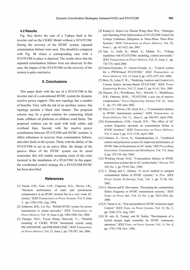
4. HVDC-STATCOM Simulations
4.1 Case Studies
Comparative studies of two system configurations of
the CIGRE model (one with a STATCOM and the other
without a STATCOM) were preformed. In these cases, the
consideration was the converter transformer energization
and its resulting saturation, which causes voltage and
current distortion and repeated commutation failures at the
inverter end. The results with two fault cases (either
1-phase or 3-phase faults at the inverter bus) are presented
below.
Inverter
Time 1.400 1.450 1.500 1.550 1.600 1.650 1.700 1.750 1.800
-1.50
-1.00
-0.50
0.00
0.50
1.00
1.50
V o l t a g e
( p u )
AC Volts (RMS) AC Voltage
-1.00
-0.50
0.00
0.50
1.00
1.50
2.00
2.50
3.00
3.50
( p u )
DC Volts DC Current
(a)
Inverter
1.400 1.450 1.500 1.550 1.600 1.650 1.700 1.750 1.800
-2.00
-1.50
-1.00
-0.50
0.00
0.50
1.001.50
2.00
V o l t a g e
( p u )
AC Volts (RMS) AC Voltage_inv
-1.00
-0.50
0.00
0.50
1.00
1.50
2.00
2.50
3.00
3.50
( p u )
DC Volts DC Current
(b)
Fig. 8. Response of the HVDC system in the case of
considering the Saturation Characteristics of
Transformer. (At 3-phase grounded fault).
7/31/2019 8-JPE 09-40
http://slidepdf.com/reader/full/8-jpe-09-40 10/11
Dynamic Coordination Strategies between HVDC and STATCOM 901
4.2 Results
Fig. 8(a) shows the case of a 3-phase fault at the
inverter end on the CIGRE Model without a STATCOM.
During the recovery of the HVDC system, repeated
commutation failures were seen. This should be compared
with Fig. 8b where a corresponding case with a
STATCOM in place is depicted. The results show that the
repeated commutation failures were not observed. In this
case, the impact of the STATCOM on the recovery of the
system is quite conclusive.
5. Conclusions
This paper deals with the use of a STATCOM at the
inverter end of a conventional HVDC system for dynamic
reactive power support. This new topology has a number
of benefits. First, with the aid of an auxiliary source, this
topology permits a black start feature. The proposed
scheme may be a good solution for connecting island
loads, offshore oil platforms or offshore wind farms. The
proposed solution can be used with both cables and
overhead lines. Second, with the reactive power
coordination between STATCOM and HVDC systems, it
offers robustness in recovery from commutation failures,
and other faults in the system. Third, with the ability of theSTATCOM to act as an active filter, the design of the
passive filters of the HVDC system can be eased
somewhat; this will enable recouping some of the costs
incurred in the installation of a STACOM. In this paper,
the coordinated control strategy for a STATCOM-HVDC
has been described.
References
[1] Nayak, O.B.; Gole, A.M.; Chapman, D.G.; Davies, J.B.;,
“Dynamic performance of static and synchronous
compensators at an HVDC inverter bus in a very weak AC
system,” IEEE Transactions on Power Systems, Vol. 9, Issue
3, pp. 1350-1358, Aug. 1994.
[2] Andersen, B.R.; Lie Xu;, “Hybrid HVDC system for power
transmission to island networks,” IEEE Transactions on
Power Delivery, Vol. 19, Issue 4, pp. 1884-1890, Oct. 2004.
[3] Faruque, M.O.; Yuyan Zhang; Dinavahi, V.;, “Detailed
modeling of CIGRE HVDC benchmark system using
PSCAD/EMTDC and PSB/SIMULINK,” IEEE Transactions
on Power Delivery, Vol. 21, Issue 1, pp. 378-387, Jan. 2006.
[4] Kuang Li; Jinjun Liu; Zhaoan Wang; Biao Wei;, “Strategies
and Operating Point Optimization of STATCOM Control for
Voltage Unbalance Mitigation in Three-Phase Three-Wire
Systems,” IEEE Transactions on Power Delivery, Vol. 22,
Issue 1, pp. 413-422, Jan. 2007.[5] Jain, A.; Joshi, K.; Behal, A.; Mohan, N.;, “Voltage
regulation with STATCOMs: modeling, control and results,”
IEEE Transactions on Power Delivery, Vol. 21, Issue 2, pp.
726-735, April 2006.
[6] Garica-Gonzalez, P.; Garcia-Cerrada, A.;, “Control system
for a PWM-based STATCOM,” IEEE Transactions on
Power Delivery, Vol. 15, Issue 4, pp. 1252-1257, Oct. 2000.
[7] Shen, D.; Lehn, P. W.;, “Modeling Analysis and Control of a
Current Source Inverter-Based STATCOM,” IEEE Power
Engineering Review, Vol. 21, Issue 11, pp. 61-61, Nov. 2001.
[8] Hanson, D.J.; Woodhouse, M.L.; Horwill, C.; Monkhouse,
D.R.; Osborne, M.M.;, “STATCOM: a new era of reactive
compensation,” Power Engineering Journal, Vol. 16, Issue
3, pp. 151-160, June 2002.
[9] Thio, C.V.; Davies, J.B.; Kent, K.L.;, “Commutation failures
in HVDC transmission systems,” IEEE Transactions on
Power Delivery, Vol. 11, Issue 2, pp. 946-957, April 1996.
[10] Kristmundsson, G.M.; Carroll, D.P., “The effect of AC
system frequency spectrum on commutation failure in
HVDC inverters,” IEEE Transactions on Power Delivery,
Vol. 5, Issue 2, pp. 1121-1128, April 1990.
[11] Galanos, G., Vovos, N., Giannakopoulos, G., “Combined
control and protection system for improved performance of HVDC links in the presence of AC faults,” IEE Proceedings
Generation, Transmission and Distribution, Vol. 131, Issue
4, pp. 129-139, July 1984.
[12] Working Group 14.02, “Commutation failures in HVDC
transmission systems due to AC system faults,” Electra, Vol.
169, No. 1, pp. 59-85, Dec. 1996.
[13] L. Zhang and L. Dofnas, “A novel method to mitigate
commutation failure in HVDC systems,” in Proc. IEEE
Power System Technology Conf., Vol. 1, pp. 51-56, Oct.
2002.
[14] A. Hansen and H. Havemann, “Decreasing the commutation
failure frequency in HVDC transmission systems,” IEEE
Trans. on Power Del., Vol. 15, No. 3, pp. 1022-1026, Jul.
2000.
[15] S. Tamai et al., “Fast and predictive HVDC extinction angle
Control,” IEEE Trans. on Power Systems, Vol. 12, No. 3,
pp. 1268-1275, Aug. 1997.
[16] M. sato, K. Yamaji, and M. Sekita, “Development of a
hybrid margin angle controller for HVDC continuous
operation,” IEEE Trans. on Power Systems, Vol. 11, No. 4,
pp. 1792-1798, Nov. 1996.
7/31/2019 8-JPE 09-40
http://slidepdf.com/reader/full/8-jpe-09-40 11/11
902 Journal of Power Electronics, Vol. 9, No. 6, November 2009
[17] M. Szechtman, T. Wess, and C. V. Thio, “First benchmark
Model for HVDC control studied,” Electra, Vol. 135, No. 4,
pp. 54-73, 1991.
[18] S. Nyati, S.R. Atmuri, et al., “Comparison of Voltage
Control Devices at HVDC Converter Stations Connectedto Weak AC Systems,” IEEE Transactions on Power
Delivery, Vol. 3, No. 2, pp. 684-693, April 1998.
Chan-Ki Kim obtained his M.S and his
Ph.D. in Electrical Engineering from
Chung-Ang University, Korea, in 1993 and
1996 respectively. Since 1996, he has been
with KEPRI, the R&D center of KEPCO
(Korea Electric Power Corporation). His
research interests are HVDC, Power
Electronics and Generator Control. He received a Technical
Award from the Ministry of Science & Technology, Korea and
Excellent Paper Awards from KIEE in 2002 and 2004
respectively. Currently, he is working at KEPRI. He is a Senior
Member of the Institute of Electrical and Electronics Engineers
(IEEE).
Vijay Sood obtained his B.Sc. (1st Class
Hons.) from University College, Nairobi and
his M.Sc. from Strathclyde University,
Glasgow in 1969. He obtained his Ph.D. inPower Electronics from the University of
Bradford, England in 1977. From 1969 to
1976, he was employed at the Railway Technical Centre, Derby.
From 1976 to 2006, he was employed as a Researcher at IREQ
(Hydro-Québec) in Montreal. Presently, he is on special
assignment at the University of Ontario Institute of Technology
(UOIT) in Oshawa, Ontario. He is a Fellow of the IEEE and a
member of the IEE (UK). He is also the Editor of the IEEE
Transactions on Power Delivery, Co-Editor of the CJECE and an
Associate Editor of the Journal Control Engineering Practice.
Seok-Jin Lee obtained his B.S. and M.S. in
Electrical Engineering from Seoul National
University, Seoul, Korea, in 1980 and 1982,
respectively. He was the designer of Cheju
HVDC #1 in 1992 and the manager of Cheju
HVDC #1 in 1994. His is interested in
HVDC and Power Quality. He received a First National
Electrical Engineer License from the Korea Government in 1983.
He is the author or co-author of more than 30 technical
publications and he has 5 patents related to HVDC. At present,
he is a vice-director in KEPCO (Korea Electric Power
Corporation).


![설명회일정...[설명회일정] 시간 내용 비고 09:30 ~ 09:40 인사말씀 금융위원회권대영금융혁신기획단장 09:40 ~ 09:55 금융규제샌드박스제도안내](https://img.pdfslide.tips/doc/110x75/608de4616e147a435619bd16/eoe-eoe-oee-e-ee-0930-0940-e.jpg)