Embed Size (px)
Citation preview

ICAM 2 – Heat Exchangers
27
9. Appendix 1 – Illustration of some concepts in heat exchangers 9.1. Heat Exchanger “Effectiveness”
This is defined as: maxRateTransferHeatPossibleMaximum
RateTransferHeatActualq
q==ε
The maximum heat transfer rate is for an “infinite area” counter flow heat exchanger. )(max cihihh TTCmq −= & )(max cihicc TTCmq −= & i.e. in general: )()( minmax cihi TTCmq −= & In a “real” heat exchanger )()( hohihhcicocc TTCmTTCmq −=−= &&
)()(
)()()(
)(
minmin cihi
hohihh
cihi
cicoccTTCm
TTCmTTCm
TTCm−
−=
−−
=∴&
&
&
&ε
So: cccihi
cico CmCmTTTT
&& =−−
= min)(if)()(
ε and hhcihi
hohi CmCmTTTT
&& =−−
= min)(if)()(
ε
9.2. Transfer Unit Consider a counter flow heat exchanger:
ccchhh dTCmdTCmdq && ==
cchh CmCm <&Take
)(sconstant
1
o=
>=hh
cc
c
hCmCm
dTdT
&
&
PDF created with FinePrint pdfFactory trial version http://www.fineprint.com

ICAM 2 – Heat Exchangers
28
The “operating line” is a plot of the corresponding values of Th against Tc in the exchanger (with slope so > 1 for cchh CmCm && < ). This is compared with the “equilibrium line” which is drawn such that Th = Tc (slope = 1).
For this case: )( cchh CmCm && < and ∆
=−−
=δ
εcihi
hohiTTTT
min)( CmUANTU
&= is a non-dimensional expression of the “heat exchanger size”.
The greater the number of transfer units, the closer the operating line approaches to the equilibrium line. 9.3. Comparison between LMTD factor and NTU-effectiveness approaches Compare two exchangers: [1] Perfect counter flow (as reference) [2] “Real” exchanger Each has the same cohocihihhcc TTTTCmCmUq ,,,,,,, && but their areas are different.
Then 1actual
wcounterflo ≤=A
AFt and
actual
wcounterflo)NTU(
)NTU(=tF for the same value of ε
Also the parameter S = ε for min)( CmCm cc && =
S =
cc
hhCmCm
&
&ε for min)( CmCm hh && =
parameter R =Rmin
maxR
max
minC1
)()(
orC)()(
either ===CmCm
CmCm
CmCm
hh
cc&
&
&
&
&
&
i.e. a “one-to-one” correspondence exists between the two sets of parameters.
Slope of operating line:
cico
hohi
hh
cco TT
TTCmCm
s−−
==&
&
In this situation
Rmax
min C)()(1
==CmCm
so &
&
PDF created with FinePrint pdfFactory trial version http://www.fineprint.com

ICAM 2 – Heat Exchangers
29
9.4. Temperature “cross” in a shell and tube heat exchanger Consider a one shell-pass, two tube-pass heat exchanger:
In the above case cchh CmCm && <
hohi
cico
hohi
cohicicocohi
hohi
cihi
hohi
TTTT
TTTTTTTT
TTTTTT
−−
+−−
=−+−
−=
−−
=∴1
ε ……..(9.4.1)
But if there is a temperature cross: hoco TT = and if min)( CmCm hh && =
then hohi
cico
cc
hhTTTT
CmCm
CmCm
−−
===&
&
&
&
max
minR )(
)(C
Substituting for CR in Equation 9.4.1: RC1
1+
=cε
This can be drawn on the appropriate NTU plot to illustrate the occurrence of the temperature cross.
A temperature cross is imminent when: coho TT =
but )()(
)(
min cihi
cicoccTTCm
TTCm−
−=
&
&ε
or )()(
)(
min cihi
hohihhTTCm
TTCm−
−=
&
&ε
PDF created with FinePrint pdfFactory trial version http://www.fineprint.com

ICAM 2 – Heat Exchangers
30
9.5. Temperature distribution in a (1,2) shell and tube heat exchanger The detailed temperature distribution depends on the relative paths taken by the shell and tube fluids. 9.6. Graphical representation of Heat Exchangers in Series
Take hhCmCm && =min)( so slope 1>om& Overall effectiveness: From the diagram, Similarly: Thus
iεεεε === 321
o
o
cihi
hohiTTTT
∆=
−−
=δ
ε
oooo
oo
ooo
oommmy
y/1
1/1
/1)/(1
4ε
εδ
δδ
δ−
−=
∆−∆−
=−∆
−∆=
ooo myy
myy
myy
/11
/11
/11
3
3
3
4
2
2
2
3
1
1
1
2ε
εε
εε
ε−
−=
−−
=−
−=
oi oi
immy
yyy
yy
yy
/11
/113
11
2
2
3
3
4
1
4ε
εε
ε−
−=
−−
=⋅⋅= ∏=
PDF created with FinePrint pdfFactory trial version http://www.fineprint.com

ICAM 2 – Heat Exchangers
31
In general, for “n” passes: ………(9.6.1) Inverting: Solving for ε , If all the units are identical ( pi εε = ) and we put CR = 1/mo (Capacity Ratio)
{ }
{ } R/1
R
/1R
C)1/()C1(
1)1/()C1(
−−−
−−−= n
pp
npp
εε
εεε or inverting:
{ }
{ } R/1
R
/1R
C)1/()C1(1)1/()C1(
−−−
−−−= n
n
pεε
εεε …..….(9.6.2)
Special case of CR = 1
∏=
−−
=−
− n
i oi
i
o mm 1 /11
/11
εε
εε
∏=
−−
=−
− n
i i
oio mm
1 1/1
1/1
εε
εε
∏
∏
=
=
−
−−
−
−−
=n
i i
i
n
i i
i
1 o
o
1
o
m1
1m/1
11
m/1
εε
εε
ε
From the above expression, for the special case of CR = 1, ε is undefined. The diagram on the left may be used to investigate the situation. In this case the operating line has a slope of unity. We consider “n” identical exchangers in series. The strip AXZ'C represents the first of these. As before:
o
oDFDE
∆==
δε
{ } { }
p
p
p
p
nn
nnn
nn
n
ε
εε
εεε
δδδ
ε
δδδ
εδδ
δε
)1(1:tosimplifiesThis
/1//1/
)/(/
/ Zbut Z
)ZZ(XY and strips n"" are theresince/n AXXYbut XZXY
:exchangerfirst For the
oooo
oo
ooo
ooo
oop
−+=
−−=
∆−∆−∆
=∴
−−∆=∴−=′
′−∆====
PDF created with FinePrint pdfFactory trial version http://www.fineprint.com

ICAM 2 – Heat Exchangers
32
Heat exchangers in Series-Parallel configuration
In general for “n” passes: ∏=
−−
=−
− n
i oi
i
o mm 1 /11
/11
εε
εε
For the special case where CR = 0, then ∞→om
{ } { }∏∏==
−−=−=−∴n
ii
n
ii
1111and11 εεεε
Thus, for CR = 0, the temperature of the secondary fluid remains “constant” and so the situation applies to any type of exchanger and any type of connection for the secondary fluid (series, parallel or combinations of the two). 10. Reference Books
1. JANNA, William S, “Engineering Heat Transfer”, Van-Nostrand Reinhold International 2. HOLMAN, J P, “Heat Transfer”, McGraw-Hill 3. KREITH, F, “Transmission de la Chaleur” (Translation of “Principles of Heat Transfer”),
Masson et Cie. 4. KAYS, W M and LONDON, A L, “Compact Heat Exchangers”, McGraw-Hill 5. SACADURA, J F, “Initiation aux Transferts Thermiques”, Technique et Documentation.
6. SHAMSUNDAR, N, “A property of the log-mean temperature-difference correction
factor”, Mechanical Engineering News, 19(3), 14-15, 1982. 7. LIENHARD, J (iv) and LIENHARD, J (v), “A Heat Transfer Textbook”, 3rd edition
(August 2001). Available for download on the Internet at: http://web.mit.edu/lienhard/www/ahtt.html
PDF created with FinePrint pdfFactory trial version http://www.fineprint.com

ICAM 2 – Heat Exchangers
33
11. Tables of Theoretical Relationships for Heat Exchangers 11.1. Heat exchanger effectiveness relations
min)(NTUN CmUA &== maxminR )()(C mCmC= =ε effectiveness
Flow geometry Relation Double pipe: Parallel-flow
[ ]{ }
)C1()C1(Nexp1
R
R+
+−−=ε
Counter-flow
[ ]
[ ])C1(NexpC1)C1(Nexp1
RR
R−−−
−−−=ε
Counter-flow ( 1CR = )
( )1NN +=ε
Cross flow: Both fluids unmixed
−−−=
nC1)nNC(exp
exp1R
Rε where 22.0Nn −=
Both fluids mixed
1
R
RN1
)NCexp(1C
)Nexp(11
−
−
−−+
−−=ε
max)( Cm& mixed, min)( Cm& unmixed
( ) [ ]{ }))Nexp(1(Cexp1C1 RR −−−−=ε
max)( Cm& unmixed, min)( Cm& mixed
( )[ ]{ })NCexp(1C1exp1 RR −−−−=ε
Shell and tube: One shell pass, 2, 4, 6 tube passes
{ }{ }
1
2/12 R
2/12 R2/12
R)C1(exp1)C1(exp1
)C1(12−
+−−
+−++++=
NNCRε
All exchangers with CR = 0:
)Nexp(1 −−=ε
PDF created with FinePrint pdfFactory trial version http://www.fineprint.com

ICAM 2 – Heat Exchangers
34
11.2. NTU relations for heat exchangers
maxminR )()(C mCmC= =ε effectiveness min)(NTUN CmUA &==
Flow geometry Relation Double pipe: Parallel-flow
{ }
)C1()C1(1log
NR
R+
+−−=
εe
Counter-flow
−−−
=ε
ε
RR C-11log
)C1(1N e
Counter-flow (CR=1)
)-(1
Nε
ε=
Cross flow: max)( Cm& mixed, min)( Cm& unmixed
[ ])C1(log)C/1(1logN RR ε−+−= ee
max)( Cm& unmixed, min)( Cm& mixed
[ ])1(logC1log)C/1(N RR ε−+−= ee
Shell and tube: One shell pass, 2, 4, 6 tube passes
++−−
+−−−+−= −
2/12RR
2/12RR2/12
R)C1(C1)2()C1(C1)2(
log)C1(Nε
εe
All exchangers with CR=0:
)1(logN ε−−= e
PDF created with FinePrint pdfFactory trial version http://www.fineprint.com

ICAM 2 – Heat Exchangers
35
12.1. Shell and Tube Heat Exchanger 12.2. Correction Factor Plot for (1,2) Shell and Tube Heat Exchanger
12. Charts
PDF created with FinePrint pdfFactory trial version http://www.fineprint.com

ICAM 2 – Heat Exchangers
36
12.3. Ten Broeck plot for outlet temperature of a (1,2) Shell and Tube Heat Exchanger 12.4. & 12.5. Effectiveness-NTU plots for (a) Double pipe; (b) (1,2) Shell and Tube Exchangers
PDF created with FinePrint pdfFactory trial version http://www.fineprint.com

ICAM 2 – Heat Exchangers
37
12.6. Correction Factor Plot for Crossflow Heat Exchanger with Both Fluids Unmixed
12.7. Effectiveness-NTU Plot for Crossflow Heat Exchanger with Both Fluids Unmixed
PDF created with FinePrint pdfFactory trial version http://www.fineprint.com

ICAM 2 – Heat Exchangers
38
12.8. Correction Factor Plot for Crossflow Heat Exchanger with One Fluid Mixed
12.9. Effectiveness-NTU Plot for Crossflow Heat Exchanger with One Fluid Mixed
PDF created with FinePrint pdfFactory trial version http://www.fineprint.com
ICAM 2 – Heat Exchangers
39
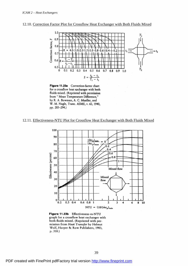
12.10. Correction Factor Plot for Crossflow Heat Exchanger with Both Fluids Mixed
12.11. Effectiveness-NTU Plot for Crossflow Heat Exchanger with Both Fluids Mixed
PDF created with FinePrint pdfFactory trial version http://www.fineprint.com