Embed Size (px)
Citation preview
8/2/2019 9500 Mxc Datasheet
http://slidepdf.com/reader/full/9500-mxc-datasheet 1/5
Alcatel-Lucent 9500 Microwave Cross-Connect
The Alcatel-Lucent 9500 Microwave Cross-Connect (MXC) is a exible, multiservice wireless transport platform
for medium- to high-capacity mixed trafc. Offering a new generation of digital, point-to-point microwave radio
capabilities, the 9500 MXC provides an effective way to meet the growing demand for high-capacity applications.
The compact Alcatel-Lucent 9500 MXC
supports SDH/SONET and “super PDH”
applications with higher exibility
aorded by its integrated cross-
connection capabilities. It can also
support fxed applications such as DSL
and WiMAX backhauling, due to its
multiple interaces, including PDH, SDH
and Ethernet with integrated Layer-2
switching. The 9500 MXC is a reliable,complete, homogeneous series, rom
6 GHz to 38 GHz. Its unique network
management capabilities serve both
small and large networks, and its
compact design enables easy installa-
tion while ensuring that maximum
commonality is achieved across
requencies and capacities.
Benets
• Spectrum efciency to supportincreasing broadband trafc
• High reliability
• Reduced costs – with a modular
design and cost-optimized IDUs
or SDH and Ethernet applications
• Easy installation and reduced cabling
• Enhanced customer satisaction with
QoS management
Applications
• Wireless point-to-point
• Mobile, private and carrier
network inrastructures
• SDH, high-capacity PDH and
Ethernet radio transmissions
• Local trafc aggregation
• High-capacity aggregation• Backhauling or DSL, WiMAX
and PC networks
Features
• High-capacity transport or mixed
data and TDM trafc
¬ SDH capacity up to 2xSTM-1
¬ PDH capacity up to 106xE1 or 8xE3
¬ Ethernet capacity up to 200 Mb/s
ull-duplex
¬ Gigabit Ethernet capacity up to
600 Mb/s with link aggregation
and Layer 2 switch integrated
• High-integration design that delivers
high reliability
• Terminal Integrated Solution (IDU)
or 1xSTM-1, 20xE1 or Fast Ethernet +
8xE1 confgurations
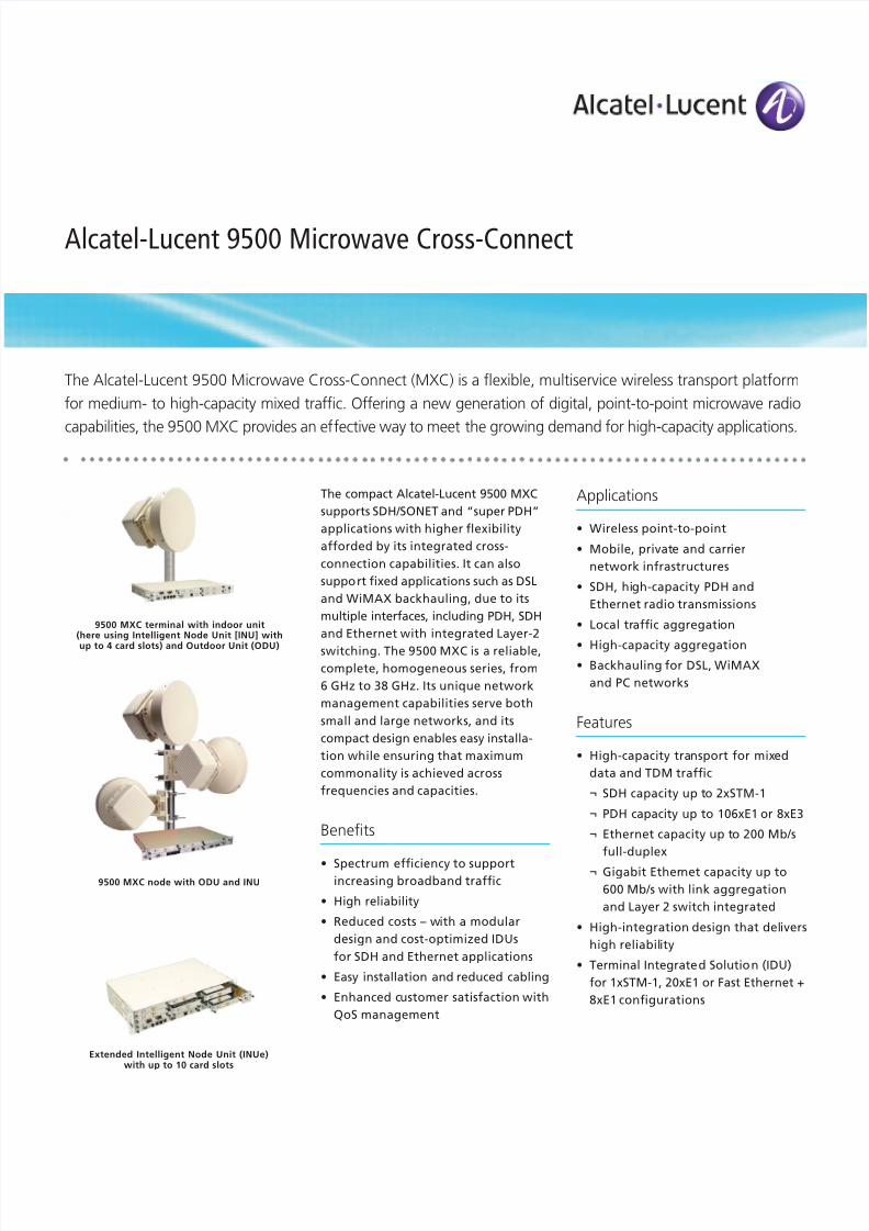
Extended Intelligent Node Unit (INUe)with up to 10 card slots
9500 MXC node with ODU and INU
9500 MXC terminal with indoor unit(here using Intelligent Node Unit [INU] with
up to 4 card slots) and Outdoor Unit (ODU)
8/2/2019 9500 Mxc Datasheet
http://slidepdf.com/reader/full/9500-mxc-datasheet 2/5
Alcatel-Lucent 9500 Microwave Cross-Connect | Data Sheet2
• Node confguration and integrated
cross-connect unctionalities
(using Intelligent Node Unit [INU]
or extended Intelligent Node Unit
[INUe])
¬ Flexible aggregate capacity
sharing between E1s and Ethernet
¬ Powerul embedded trafcrouting with E1 cross-connect
¬ Nodal capabilities supporting up
to six radio paths (with INUe)
• Universal ODU (16, 32, 64, 128 and
256 QAM; 64 Mb/s to 311 Mb/s)
• Java™-based crat terminal
• Full sotware confgurable modulation
and capacity
• Highly modular architecture
Technical specications
Configurations
• Unprotected
• 1+1 hot-standby
• 1+1 space diversity• 1+1 frequency diversity
• Co-channel cross-pol operation(XPIC)
• Repeater with traffic add-drop
• 3-, 4-, 5- and 6-way nodalconfiguration with traffic routing
• E1 and STM-1 line protection
System-level specifications
• Operating frequencies: 6, 7, 8,10.5, 11, 13, 15, 18, 23, 26, 28and 38 GHz
• Modulation options: QPSK, 16,32, 64, 128 and 256 QAM
• Capacity ranges: 32, 40, 48, 52,64, 75, 93 and 106 E1; 1, 2, 3, 4,5, 6, 7 and 8 E3; 1 and 2 STM-1
Power requirements
• Input voltage range:-40 V DC to -60 V DC
• Power consumption
¬ IDU: 10 W
¬ INU and INUe: dependent oncards installed:
- Radio Access Card: 6 W
- Digital Access Card: 3 W- Node Control Card: 4 W
- Node Protection Card: 4 W
- Fan Unit: 2 W
¬ ODU: 50 W maximum
Dimensions
IDU and INU
• Height: 44.5 mm (1.75 in.)
• Width: 480 mm (18.9 in.)
• Depth: 300 mm (11.8 in.)
INUe
• Height: 89 mm (3.50 in.)
• Width: 480 mm (18.90 in.)
• Depth: 300 mm (11.81 in.)
ODU
• Height: 284 mm (11.18 in.)
• Width: 284 mm (11.18 in.)
• Depth: 162 mm (6.38 in.)
Environmental
• IDU and INU: -5°C to +45°C(23°F to 113°F)
• INUe: -50°C to +65°C(-58°F to +149°F)
• ODU: -33°C to +55°C(-27°F to +131°F)
Standards compliance
• EMC: EN 301 489
• Operation
¬ ODUs: ETS 300 019, Class 4.1
¬ IDUs: ETS 300 019, Class 3.2
• Storage: ETS 300 019, Class 1.2
• Transportation: ETS 300 019,Class 2.3
• Radio frequency: EN 302 217
• Safety: EN 60950
• Water ingress (ODUs)IEC 60529 (IPX6)
Modulation scheme:
• QPSK, 16 QAM, 32 QAM,64 QAM, 128 QAM, 256 QAM(software selectable)
Capacity
• PDH ETSI: 20,40, 52, 64, 75, 93and 106 E1
• SDH: STM-1, 2xSTM-1 single-carrier at 56 MHz, 2xSTM-1 XPIC
• LAN: 4x 10/100 BASE-T(X), 1000BASE-LX, 3x1000 BASE-T
Channel spacing (MHz) andmodulation options
• 7 (5 E1), 14 (10 E1), 28 (20 E1)for QPSK
• 3, 5 (E1), 7 (10 E1), 14 (20 E1),28 (3 2E1), 28(40 E1), 56 (64 E1),56 (75 E1), 56 (STM-1) for 16 QAM
• 14 (27 E1), 28 (52 E1) for 32 QAM
• 7 (16 E1), 14 (32 E1), 28 (64 E1),56 (100 E1), 40 (STM-1) for64 QAM
• 28 (75 E1), 28 (STM-1), 28(1xSTM1 + 1xE1), 56 (2xSTM-1)for 128 QAM
• 28 (93 E1) for 256 QAM
Configurations
• 1+0, 1+1 HSB/SD/FD, 1+1 HSB XP,2+0
8/2/2019 9500 Mxc Datasheet
http://slidepdf.com/reader/full/9500-mxc-datasheet 3/5
Alcatel-Lucent 9500 Microwave Cross-Connect | Data Sheet 3
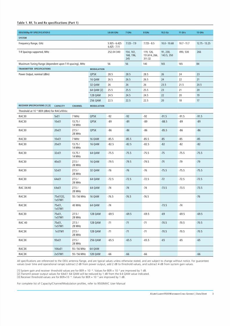
Table 1. RF, Tx and Rx specifica tions (Part 1)
ODU300hp RF SPECIFICATIONS L6/U6 GHz 7 GHz 8 GHz 10,5 Gz 11 GHz 13 GHz
SYSTEM
Frequency Range, GHz 5.925 - 6.4256.425 - 7.11
7.125 - 7.9 7.725 - 8.5 10.0 - 10.68 10.7 - 11.7 12.75 - 13.25
T-R Spacings supported, MHz 252.04 340 154, 161,168, 196,245
119, 126,151.614, 266 ,311.32
91, 230,143.5, 350
490, 530 266
Maximum Tuning Range (dependent upon T-R spacing), MHz 56 56 140 165 165 84
TRANSMITTER SPECIFICATIONS MODULATION
Power Output, nominal (dBm) QPSK 28.5 28.5 28.5 26 24 23
16 QAM 26.5 26.5 26.5 24 22 21
32 QAM 26 26 26 23.5 21.5 20.5
64 QAM [2] 25.5 25.5 25.5 23 21 20
128 QAM 24.5 24.5 24.5 22 20 19
256 QAM 22.5 22.5 22.5 20 18 17
RECEIVER SPECIFICATIONS [1] [3] CAPACITY CHANNEL MODULATION
Threshold at 10 -6 BER (dBm) for RACs/IDUs:
RAC30 5xE1 7 MHz QPSK -92 -92 -92 -91.5 -91.5 -91.5
RAC30 10xE1 13.75 /14 MHz
QPSK -89 -89 -89 -88.5 -89 -89
RAC30 20xE1 27.5 /28 MHz
QPSK -86 -86 -86 -85.5 -86 -86
RAC30 10xE1 7 MHz 16 QAM -85.5 -85.5 -85.5 -85 -85 -85
RAC30 20xE1 13.75 /14 MHz
16 QAM -82.5 -82.5 -82.5 -82 -82 -82
RAC30 32xE1 13.75 /14 MHz
64 QAM -75.5 -75.5 -75.5 -75 -75.5 -75.5
RAC30 40xE1 27.5 /28 MHz
16 QAM -79.5 -79.5 -79.5 -79 -79 -79
RAC30 52xE1 27.5 /28 MHz 32 QAM -76 -76 -76 -75.5 -75.5 -75.5
RAC30 64xE1 27.5 /28 MHz
64 QAM -72.5 -72.5 -72.5 -72 -72.5 -72.5
RAC 3X/40 64xE1 27.5 /28 MHz
64 QAM -74 -74 -74 -73.5 -73.5 -73.5
RAC3X 75xE1[3],1xSTM1
55 / 56 MHz 16 QAM -76.5 -76.5 -76.5 -76
RAC3X 75xE1,1xSTM1
40 MHz 64 QAM -74 -73.5 -74
RAC30 75xE1,1xSTM1
27.5 /28 MHz
128 QAM -69.5 -69.5 -69.5 -69 -69.5 -69.5
RAC 40 75xE1,1xSTM1
27.5 /28 MHz
128 QAM -71 -71 -71 -70.5 -70.5 -70.5
RAC3X 1xSTM1 27.5 /28 MHz
128 QAM -71 -71 -71 -70.5 -70.5 -70.5
RAC3X 93xE1 27.5 /28 MHz
256 QAM -65.5 -65.5 -65.5 -65 -65 -65
RAC3X 106xE1 55 / 56 MHz 64 QAM
RAC3X 2xSTM1 55 / 56 MHz 128 QAM -66 -66 -66 -66
All specications are referenced to the ODU antenna ange, and are typical values unless otherwise stated, and are subject to change without notice. For guaranteedvalues (over time and operational range) subtract 2 dB from power output, add 2 dB to threshold values, and subtract 4 dB from sys tem gain values.
[1] System gain and receiver threshold values are for BER = 10-6. Values for BER = 10 -3 are improved by 1 dB.[2] Transmit power output values for 64xE1 64 QAM will be reduced by 1 dB from the 6 4 QAM value indicated.[3] Receiver threshold values are for BER=10-6. Values for BER = 10 -3 are improved by 1 dB.
For complete list of Capacity/Channel/Modulation proles, refer to 9500MXC User Manual
8/2/2019 9500 Mxc Datasheet
http://slidepdf.com/reader/full/9500-mxc-datasheet 4/5
Alcatel-Lucent 9500 Microwave Cross-Connect | Data Sheet4
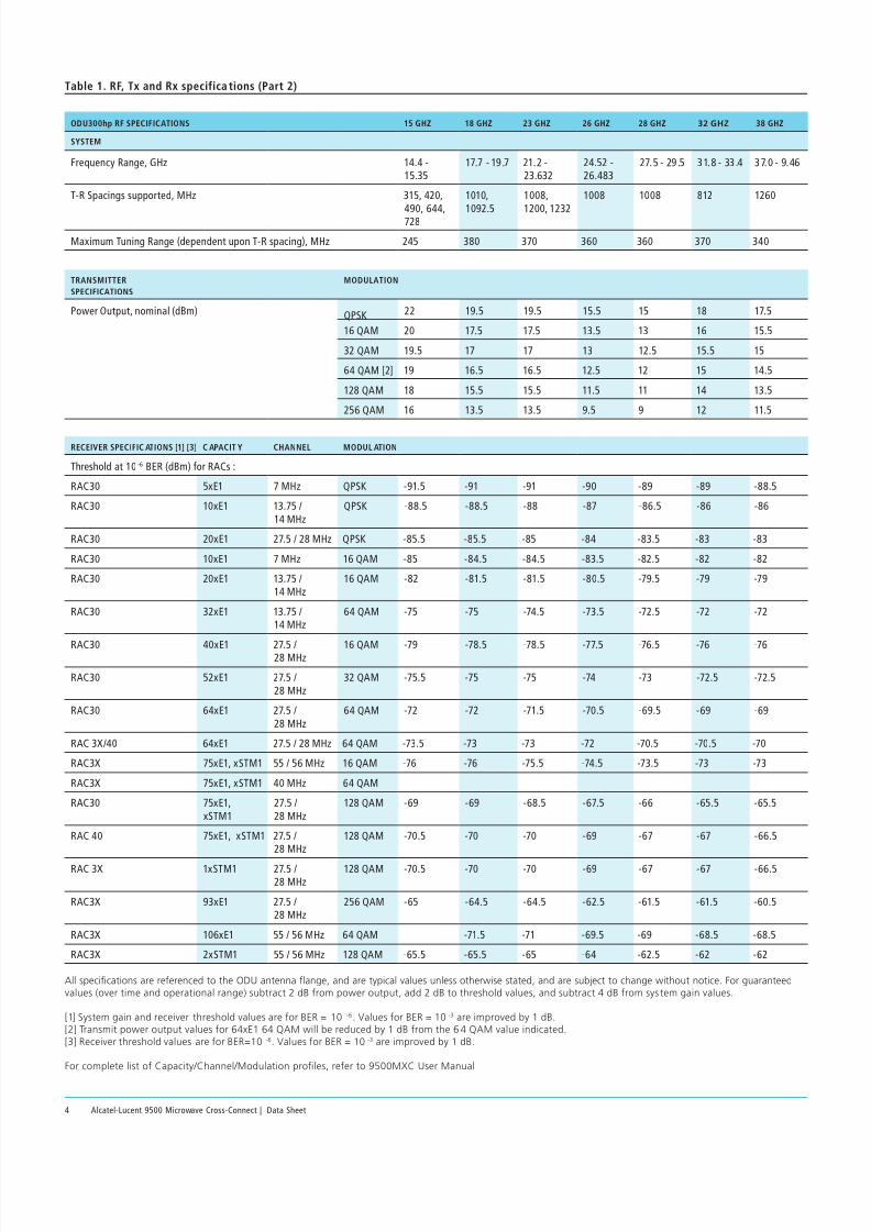
Table 1. RF, Tx and Rx specifica tions (Part 2)
ODU300hp RF SPECIFICATIONS 15 GHZ 18 GHZ 23 GHZ 26 GHZ 28 GHZ 32 GHZ 38 GHZ
SYSTEM
Frequency Range, GHz 14.4 -15.35
17.7 - 19.7 21.2 -23.632
24.52 -26.483
27.5 - 29.5 31.8 - 33.4 37.0 - 9.46
T-R Spacings supported, MHz 315, 420,490, 644,728
1010,1092.5
1008,1200, 1232
1008 1008 812 1260
Maximum Tuning Range (dependent upon T-R spacing), MHz 245 380 370 360 360 370 340
TRANSMITTER
SPECIFICATIONS
MODULATION
Power Output, nominal (dBm) QPSK 22 19.5 19.5 15.5 15 18 17.5
16 QAM 20 17.5 17.5 13.5 13 16 15.5
32 QAM 19.5 17 17 13 12.5 15.5 15
64 QAM [2] 19 16.5 16.5 12.5 12 15 14.5
128 QAM 18 15.5 15.5 11.5 11 14 13.5
256 QAM 16 13.5 13.5 9.5 9 12 11.5
RECEIVER SPECIFIC ATIONS [1] [3] C APACIT Y CHANNEL MODUL ATION
Threshold at 10 -6 BER (dBm) for RACs :
RAC30 5xE1 7 MHz QPSK -91.5 -91 -91 -90 -89 -89 -88.5
RAC30 10xE1 13.75 /14 MHz
QPSK -88.5 -88.5 -88 -87 -86.5 -86 -86
RAC30 20xE1 27.5 / 28 MHz QPSK -85.5 -85.5 -85 -84 -83.5 -83 -83
RAC30 10xE1 7 MHz 16 QAM -85 -84.5 -84.5 -83.5 -82.5 -82 -82
RAC30 20xE1 13.75 /14 MHz
16 QAM -82 -81.5 -81.5 -80.5 -79.5 -79 -79
RAC30 32xE1 13.75 /14 MHz
64 QAM -75 -75 -74.5 -73.5 -72.5 -72 -72
RAC30 40xE1 27.5 /28 MHz 16 QAM -79 -78.5 -78.5 -77.5 -76.5 -76 -76
RAC30 52xE1 27.5 /28 MHz
32 QAM -75.5 -75 -75 -74 -73 -72.5 -72.5
RAC30 64xE1 27.5 /28 MHz
64 QAM -72 -72 -71.5 -70.5 -69.5 -69 -69
RAC 3X/40 64xE1 27.5 / 28 MHz 64 QAM -73.5 -73 -73 -72 -70.5 -70.5 -70
RAC3X 75xE1, xSTM1 55 / 56 MHz 16 QAM -76 -76 -75.5 -74.5 -73.5 -73 -73
RAC3X 75xE1, xSTM1 40 MHz 64 QAM
RAC30 75xE1,xSTM1
27.5 /28 MHz
128 QAM -69 -69 -68.5 -67.5 -66 -65.5 -65.5
RAC 40 75xE1, xSTM1 27.5 /28 MHz
128 QAM -70.5 -70 -70 -69 -67 -67 -66.5
RAC 3X 1xSTM1 27.5 /28 MHz
128 QAM -70.5 -70 -70 -69 -67 -67 -66.5
RAC3X 93xE1 27.5 /28 MHz
256 QAM -65 -64.5 -64.5 -62.5 -61.5 -61.5 -60.5
RAC3X 106xE1 55 / 56 MHz 64 QAM -71.5 -71 -69.5 -69 -68.5 -68.5
RAC3X 2xSTM1 55 / 56 MHz 128 QAM -65.5 -65.5 -65 -64 -62.5 -62 -62
All specications are referenced to the ODU antenna ange, and are typical values unless otherwise stated, and are subject to change without notice. For guaranteedvalues (over time and operational range) subtract 2 dB from power output, add 2 dB to threshold values, and subtract 4 dB from sys tem gain values.
[1] System gain and receiver threshold values are for BER = 10-6. Values for BER = 10 -3 are improved by 1 dB.[2] Transmit power output values for 64xE1 64 QAM will be reduced by 1 dB from the 6 4 QAM value indicated.[3] Receiver threshold values are for BER=10-6. Values for BER = 10 -3 are improved by 1 dB.
For complete list of Capacity/Channel/Modulation proles, refer to 9500MXC User Manual
8/2/2019 9500 Mxc Datasheet
http://slidepdf.com/reader/full/9500-mxc-datasheet 5/5
www.alcatel-lucent.com Alcatel, Lucent, Alcatel-Lucent and the Alcatel-Lucent logoare trademarks of Alcatel-Lucent. All other trademarks are the property of their respective owners.The information presented is subject to change without notice. Alcatel-Lucent assumes no responsibilityfor inaccuracies contained herein. Copyright © 2010 Alcatel-Lucent. All rights reserved.CPG4688100404 (05)
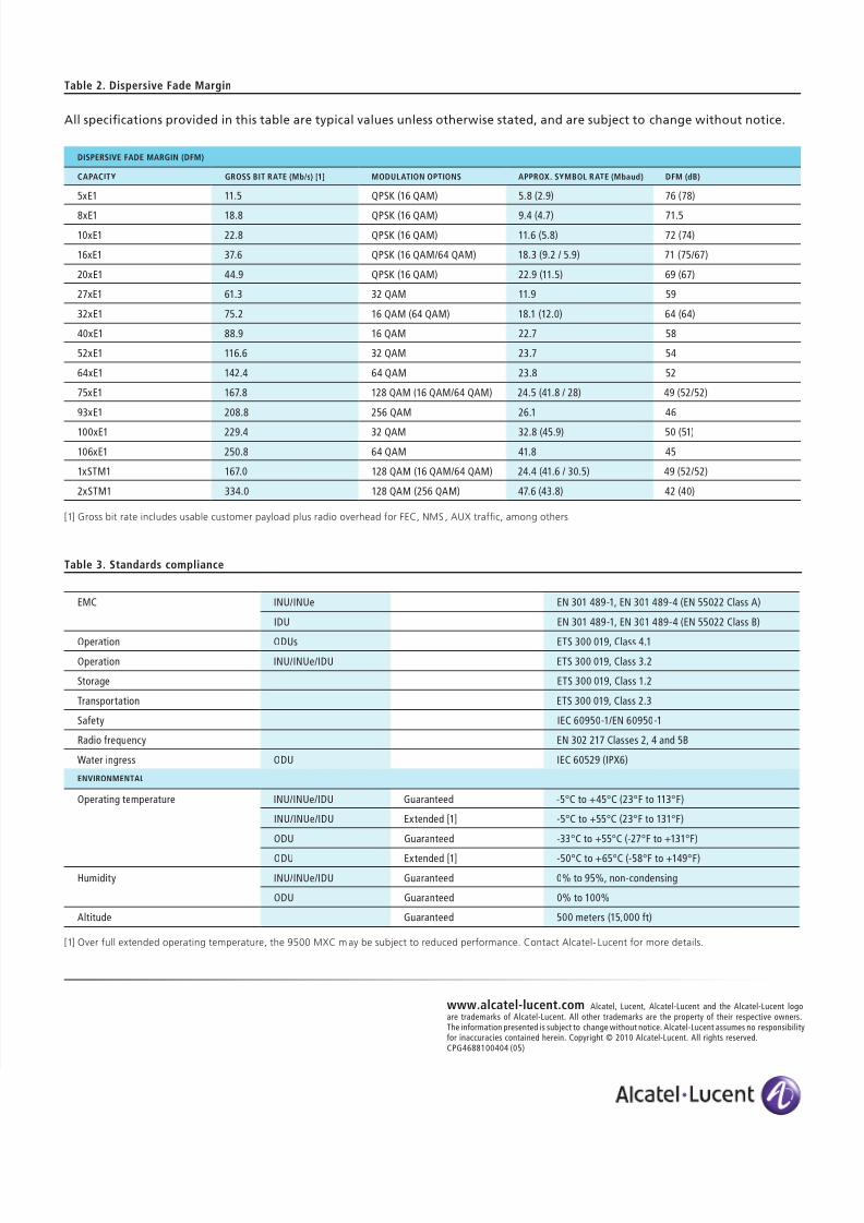
Table 3. Standards compliance
EMC INU/INUe EN 301 489-1, EN 301 489-4 (EN 55022 Class A)
IDU EN 301 489-1, EN 301 489-4 (EN 55022 Class B)
Operation ODUs ETS 300 019, Class 4.1
Operation INU/INUe/IDU ETS 300 019, Class 3.2
Storage ETS 300 019, Class 1.2
Transportation ETS 300 019, Class 2.3
Safety IEC 60950-1/EN 60950-1
Radio frequency EN 302 217 Classes 2, 4 and 5B
Water ingress ODU IEC 60529 (IPX6)
ENVIRONMENTAL
Operating temperature INU/INUe/IDU Guaranteed -5°C to +45°C (23°F to 113°F)
INU/INUe/IDU Extended [1] -5°C to +55°C (23°F to 131°F)
ODU Guaranteed -33°C to +55°C (-27°F to +131°F)
ODU Extended [1] -50°C to +65°C (-58°F to +149°F)
Humidity INU/INUe/IDU Guaranteed 0% to 95%, non-condensing
ODU Guaranteed 0% to 100%
Altitude Guaranteed 500 meters (15,000 ft)
[1] Over full extended operating temperature, the 9500 MXC may be subject to reduced performance. Contact Alcatel- Lucent for more details.
Table 2. Dispersive Fade Margin
All specifcations provided in this table are typical values unless otherwise stated, and are subject to change without notice.
DISPERSIVE FADE MARGIN (DFM)
CAPACITY GROSS BIT RATE (Mb/s) [1] MODULATION OPTIONS APPROX. SYMBOL RATE (Mbaud) DFM (dB)
5xE1 11.5 QPSK (16 QAM) 5.8 (2.9) 76 (78)
8xE1 18.8 QPSK (16 QAM) 9.4 (4.7) 71.5
10xE1 22.8 QPSK (16 QAM) 11.6 (5.8) 72 (74)
16xE1 37.6 QPSK (16 QAM/64 QAM) 18.3 (9.2 / 5.9) 71 (75/67)
20xE1 44.9 QPSK (16 QAM) 22.9 (11.5) 69 (67)
27xE1 61.3 32 QAM 11.9 59
32xE1 75.2 16 QAM (64 QAM) 18.1 (12.0) 64 (64)
40xE1 88.9 16 QAM 22.7 58
52xE1 116.6 32 QAM 23.7 54
64xE1 142.4 64 QAM 23.8 52
75xE1 167.8 128 QAM (16 QAM/64 QAM) 24.5 (41.8 / 28) 49 (52/52)
93xE1 208.8 256 QAM 26.1 46
100xE1 229.4 32 QAM 32.8 (45.9) 50 (51)
106xE1 250.8 64 QAM 41.8 45
1xSTM1 167.0 128 QAM (16 QAM/64 QAM) 24.4 (41.6 / 30.5) 49 (52/52)
2xSTM1 334.0 128 QAM (256 QAM) 47.6 (43.8) 42 (40)
[1] Gross bit rate includes usable customer payload plus radio overhead for FEC, NMS , AUX trafc, among others.