Embed Size (px)
Citation preview
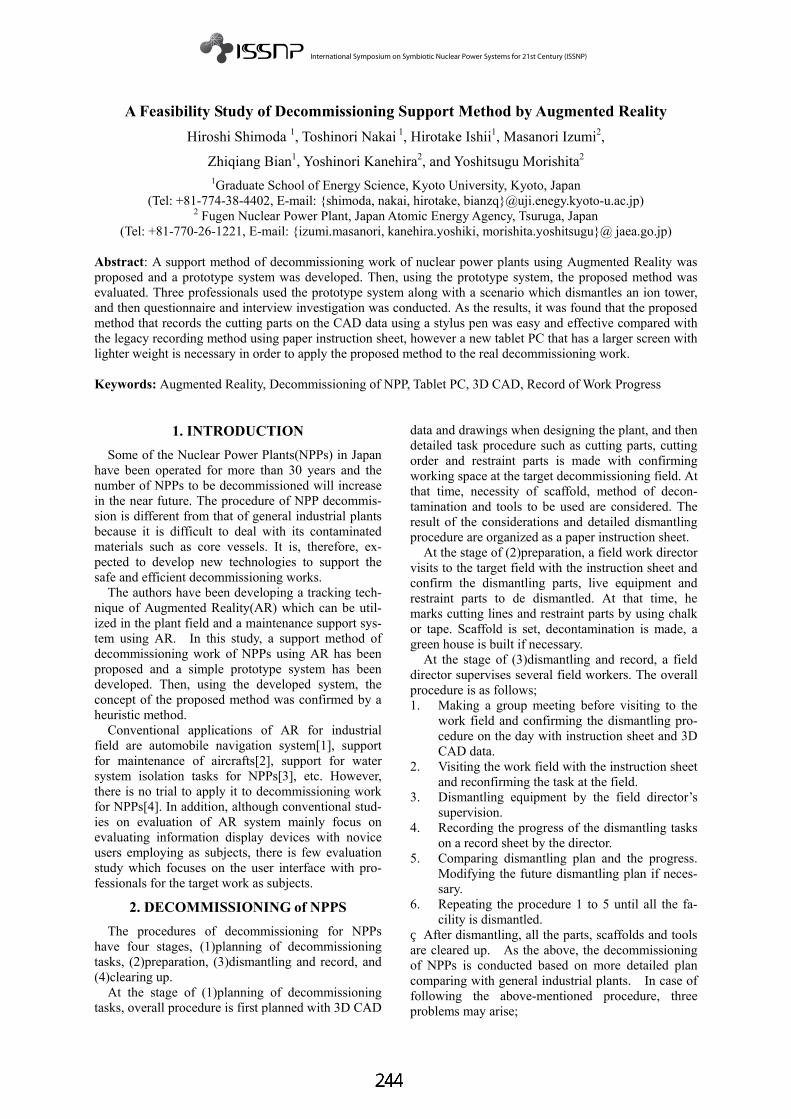
A Feasibility Study of Decommissioning Support Method by Augmented Reality Hiroshi Shimoda 1, Toshinori Nakai 1, Hirotake Ishii1, Masanori Izumi2,
Zhiqiang Bian1, Yoshinori Kanehira2, and Yoshitsugu Morishita2 1Graduate School of Energy Science, Kyoto University, Kyoto, Japan
(Tel: +81-774-38-4402, E-mail: {shimoda, nakai, hirotake, bianzq}@uji.enegy.kyoto-u.ac.jp) 2 Fugen Nuclear Power Plant, Japan Atomic Energy Agency, Tsuruga, Japan
(Tel: +81-770-26-1221, E-mail: {izumi.masanori, kanehira.yoshiki, morishita.yoshitsugu}@ jaea.go.jp)
Abstract: A support method of decommissioning work of nuclear power plants using Augmented Reality was proposed and a prototype system was developed. Then, using the prototype system, the proposed method was evaluated. Three professionals used the prototype system along with a scenario which dismantles an ion tower, and then questionnaire and interview investigation was conducted. As the results, it was found that the proposed method that records the cutting parts on the CAD data using a stylus pen was easy and effective compared with the legacy recording method using paper instruction sheet, however a new tablet PC that has a larger screen with lighter weight is necessary in order to apply the proposed method to the real decommissioning work. Keywords: Augmented Reality, Decommissioning of NPP, Tablet PC, 3D CAD, Record of Work Progress
1. INTRODUCTION Some of the Nuclear Power Plants(NPPs) in Japan
have been operated for more than 30 years and the number of NPPs to be decommissioned will increase in the near future. The procedure of NPP decommis-sion is different from that of general industrial plants because it is difficult to deal with its contaminated materials such as core vessels. It is, therefore, ex-pected to develop new technologies to support the safe and efficient decommissioning works.
The authors have been developing a tracking tech-nique of Augmented Reality(AR) which can be util-ized in the plant field and a maintenance support sys-tem using AR. In this study, a support method of decommissioning work of NPPs using AR has been proposed and a simple prototype system has been developed. Then, using the developed system, the concept of the proposed method was confirmed by a heuristic method.
Conventional applications of AR for industrial field are automobile navigation system[1], support for maintenance of aircrafts[2], support for water system isolation tasks for NPPs[3], etc. However, there is no trial to apply it to decommissioning work for NPPs[4]. In addition, although conventional stud-ies on evaluation of AR system mainly focus on evaluating information display devices with novice users employing as subjects, there is few evaluation study which focuses on the user interface with pro-fessionals for the target work as subjects.
2. DECOMMISSIONING of NPPS The procedures of decommissioning for NPPs have four stages, (1)planning of decommissioning tasks, (2)preparation, (3)dismantling and record, and (4)clearing up.
At the stage of (1)planning of decommissioning tasks, overall procedure is first planned with 3D CAD
data and drawings when designing the plant, and then detailed task procedure such as cutting parts, cutting order and restraint parts is made with confirming working space at the target decommissioning field. At that time, necessity of scaffold, method of decon-tamination and tools to be used are considered. The result of the considerations and detailed dismantling procedure are organized as a paper instruction sheet.
At the stage of (2)preparation, a field work director visits to the target field with the instruction sheet and confirm the dismantling parts, live equipment and restraint parts to de dismantled. At that time, he marks cutting lines and restraint parts by using chalk or tape. Scaffold is set, decontamination is made, a green house is built if necessary.
At the stage of (3)dismantling and record, a field director supervises several field workers. The overall procedure is as follows; 1. Making a group meeting before visiting to the
work field and confirming the dismantling pro-cedure on the day with instruction sheet and 3D CAD data.
2. Visiting the work field with the instruction sheet and reconfirming the task at the field.
3. Dismantling equipment by the field director’s supervision.
4. Recording the progress of the dismantling tasks on a record sheet by the director.
5. Comparing dismantling plan and the progress. Modifying the future dismantling plan if neces-sary.
6. Repeating the procedure 1 to 5 until all the fa-cility is dismantled.
After dismantling, all the parts, scaffolds and tools are cleared up. As the above, the decommissioning of NPPs is conducted based on more detailed plan comparing with general industrial plants. In case of following the above-mentioned procedure, three problems may arise;

1. When preparing dismantling tasks, they confirm cutting lines and restraints parts. There is a pos-sibility that they may misunderstand when there is similar equipment around there or target equipment is complicated because the field workers have to look for them by using only the instruction sheet.
2. When finishing all the tasks of the day, a field director has to record the progress of dismantling on the paper-based record sheet. It is difficult to record them exactly so that the record may have incomprehensive or insufficient information.
3. The progress should be put into the database such as 3D CAD data in order to accumulate planning know-how and modify the overall plan. This needs additional work to re-input the writ-ten information on the record sheet into the da-tabase. It is troublesome work and it may cause a mistake.
These problems may cause reduction of safety and efficiency of the tasks. It is, therefore, required to grasp of the cutting lines and restraint parts intui-tively at the workplace, and to record / input the work progress into the database easily and efficiently.
3. PROPOSAL of DECOMMISIONING SUPPORT by AR
In this study, the authors pay attention that AR can provide intuitive information display / input and re-cent NPPs have been constructed by its 3D CAD data. In order to solve three problems mentioned in chapter 2, decommissioning support method has been pro-posed by using AR and 3D CAD data. The proposed method consists of (1)reference support for cutting lines and restraint parts, and (2)record support for the progress of dismantling. The target user to be supported is a field director. Since field directors are not always accustomed to operat-ing computers, the usage of the proposed method should be comprehensive and intuitive. 3.1 Reference support for cutting lines and re-straint parts
When supporting reference of cutting lines and restraint parts, the field director carries a small tablet PC with a video camera to the work filed as shown in Fig.1. When taking pictures of the dismantling target equipment with the video camera, the image will ap-pear on the display of the small tablet PC with su-perimposing transparent 3D CAD data of the equip-ment in the same position, orientation and size by AR. The 3D CAD data are colored by the parts to be cut off. Especially, the restraint parts are colored em-phatically not to misunderstand. The user can refer the colored 3D CAD data and recognize the cutting lines and restraint parts intuitively. When referring the 3D CAD data, the user can change the position, orientation and size freely by himself. If the method mentioned above is realized, it is expected for the field director to understand the cut-
ting lines and restraint parts intuitively, comparing with the conventional method that he should refer both paper instruction sheet and real target equipment to be dismantled. DismantleTarget
VideoCamera
Small Tablet PC
3DCADIndicationof CuttingLine
Screen of Small Tablet PC
User
Indicationof CuttingProhibitedParts
DismantleTarget
VideoCamera
Small Tablet PC
3DCADIndicationof CuttingLine
Screen of Small Tablet PC
User
Indicationof CuttingProhibitedParts
Fig. 1 Reference of cutting lines by AR, 3.2 Record support for progress of dismantling
When supporting the record of dismantling pro-gress, the user carries the small tablet PC as shown in Fig.2. When finishing all the dismantling work of the day, the captured image will appear on the display with superimposing transparent 3D CAD data in the state of before dismantling work of the day. The user can record the progress by inputting the border be-tween the parts remained and already cut off by using an electronic pen (a stylus pen). At that time, the user can stop the captured image and record the progress with the paused image because the posture of the user when taking picture is different from that when using the electronic pen. Since this method is a metaphor that the user records the progress by using a pen and a record sheet, so that he can use the tablet PC intui-tively.
Target Partly Dismantled
Screen of Small Tablet PC
3DCAD
VideoCamera
Small Tablet PC
User
Target Partly Dismantled
Screen of Small Tablet PC
3DCAD
VideoCamera
Small Tablet PC
User Fig.2 Record of dismantling progress by AR. If the method mentioned above is realized, the user can record the progress of dismantling intuitively by only finding the difference between real dismantled equipment and 3D CAD data. In addition, since the record is made in the work field without delay, the database for managing the decommissioning progress can be updated immediately.
4. EVALUATION of PROPOSED METHOD

4.1 Purpose and policy of evaluation
The proposed method mentioned above employs a small tablet PC for easy portability in NPP field and intuitive operation method for novice users of PC operation. It is, however, unknown whether each function of the proposed method is effective or not, how acceptable it is for actual field directors, or what kind of problems arise in practical use. In this study, therefore, an evaluation experiment was conducted to reveal the questions above. However, it is not only laborious but also danger that the support system is really developed and used in the actual decommis-sioning work. In this study, therefore, heuristic evaluation method is employed. The heuristic method was proposed by J. Nielsen and the professionals of the target work examine the problems by using a prototype system or referring specification sheet based on a guideline[5]. Since the advantage of the proposed method is intuitive information reference and operation, it is difficult for the users to evaluate it by only its specification sheet. In this evaluation, therefore, a simple prototype system was developed and a dismantling scenario was prepared, then three professionals evaluated the prototype system with assuming that one of the plant equipment was dis-mantled along with the scenario. When evaluating, they answered the questionnaire which had been prepared referring Nielsen’s guideline. 4.2 Outline of prototype system
In order to realize the proposed method mentioned in chapter 3 as a prototype system, not only a user interface for operation but also a function which 3D CAD data is superimposed on the captured image with the same position, orientation and size of the real target equipment, should be developed. Realization of superimposing 3D CAD data In order to realize a function which 3D CAD data is superimposed on the image of real equipment, it is necessary to realize real-time tracking method which measures relative position and orientation between a video camera mounted on a small tablet PC and the target equipment in real time. In this study, the track-ing method was realized by employing linecode marker which was developed by the authors[6]. In this method, line-shaped markers are pasted in the work environment and the relative position and ori-entation between the camera and the markers can be measured in real time by capturing the image of the markers. Fig.3 shows an example of the marker.
4 cm 8 cm
0 0 0 0 01 1
4 cm
4 cm4 cm 8 cm
0 0 0 0 01 1
4 cm
4 cm4 cm
Fig.3 An example of linecode marker. Cutting function of 3D CAD data In the proposed method, when the user records the
progress of the dismantling work, he inputs the cut parts by using a stylus pen on the 3D CAD data. At that time, it is comprehensive if the 3D CAD data are also cut off. In order to realize this function, the 3D CAD data can be cut off freely by the input from the user. It is, however, difficult to realize it. In this pro-totype system, the users (professionals) use the pro-totype system along with the designated scenario, so that the function can only cut off the 3D CAD data which was designed in advance along with the sce-nario. Developed user interface and hardware The software of the prototype system was devel-oped with Microsoft VisualStudio2005 with Micro-soft Windows XP Operation System. Fig.4 shows an example of the user interface of the system. A small tablet PC, SONY VGN-UX90PS, was em-ployed as hardware of the system as shown in Fig. 5. This PC has a video camera on the backside and the LCD has touch-panel function. By using a stylus pen, the user can indicate a position on the display. Table 1 shows the outline of the specification of the PC. The computing ability of the PC realizes 7 frames per second as average frame rate where the markers are recognized by image processing and 3D CAD data are displayed.
Fig. 4 An example of user interface.
FrontBack
Camera
FrontBack
Camera
Fig.5 Hardware of prototype system. Table 1 Specification of tablet PC
VGA(640 × 480)Camera Resolution492 gWeight
3.8 mmFocal Length
150.2mm × 38.2mm × 95.0mmSize4.5Inch TFTColorLCDDisplayIntel CoreDuo U1400(1.20GHz)CPU
VGA(640 × 480)Camera Resolution492 gWeight
3.8 mmFocal Length
150.2mm × 38.2mm × 95.0mmSize4.5Inch TFTColorLCDDisplayIntel CoreDuo U1400(1.20GHz)CPU
4.3 Evaluation method
Evaluation environment

The target equipment to be dismantled in this evaluation scenario is an ion tower in water purifica-tion facility in Fugen NPP as shown in Fig.6. The shape is like a cylinder and its diameter and height is 3.7 m and 1.0 m, respectively. Fig. 7 shows the layout of the evaluation environment. The evaluator can view the ion tower from three areas which are indi-cated as “Evaluator Working Area” in Fig.7.
Front BackFront Back Fig.6 Target to be dismantled.
IonTower
IonTower
IonTower
IonTower
Wall
Control Panels for Water Purification Loop
2.0m
Motor&
Pumps
1.5m
Pipes
EvaluatorWorking Area
Marker
Dismantlingtarget
IonTower
IonTower
IonTower
IonTower
Wall
Control Panels for Water Purification Loop
2.0m
Motor&
Pumps
Motor&
Pumps
1.5m1.5m
Pipes
EvaluatorWorking Area
Marker
Dismantlingtarget
Fig.7 Layout of water purification facility. Evaluators Evaluators are three professionals of Fugen NPP, evaluator A, B and C. The evaluator A is a leader of operator group of Fugen NPP, the evaluator B be-longs to decommissioning team, and the evaluator C is an engineer who develops decommissioning technologies. Evaluation Scenario The evaluation scenario was designed based on the opinions from the above evaluators, where all the functions mentioned in chapter 3 are used at least once. In the scenario, the ion tower is dismantled in three days and the plan before dismantling is assumed as follows; (1)The first day Pipe 1, pipe 2, peeping window and upper quarter of the ion tower are dismantled in this order. (2)The second day Pipe 3, upper half and lower quarter of the ion tower are dismantled in this order.
(3)The third day Pipe 4 and the remaining parts are dismantled. In the scenario, it is assumed that the dismantling work of the second day is delayed and the lower quarter of the ion tower can not be dismantled within the second day. The plan of the third day is, therefore, modified as follows; (3)The third day (modified) Pipe 4, the lower quarter of the ion tower and the remaining parts are dismantled. Fig.8 shows examples of 3D CAD data displayed as dismantling order of the ion tower.
Next cutting parts (Blue)
Dismantled parts (Gray)
Cuttingprohibitedparts (Red)
Cutting parts for today (Light blue)
Before dismantling
After dismantlingPipe1
After dismantlingPipe2
After dismantlingPeeping window
Next cutting parts (Blue)
Dismantled parts (Gray)
Cuttingprohibitedparts (Red)
Cutting parts for today (Light blue)
Before dismantling
After dismantlingPipe1
After dismantlingPipe2
After dismantlingPeeping window
Fig.8 Examples of 3D CAD data displayed to user. Procedure of evaluation After explanation of the system and the evaluation procedure to the evaluators, they use the prototype system for approximately twenty minutes along with the scenario one by one, and answer the questionnaire immediately. Then they move to another room and are interviewed and make a group discussion. In the interview and the group discussion, they are asked to give their opinions about the reason of the question-naire answer and possibility that the proposed method can be applied to the actual decommissioning work. Questionnaire The questionnaire consists of 14 items for system function and 13 items for usability based on the guideline of the heuristic evaluation method. The evaluators answer each question as 1 to 5 (1:completely disagree, 2:disagree, 3:fair, 4:agree, 5:completely agree). In addition, free description is added in the last of the questionnaire and they answer other problems and points to be improved. 4.4 Evaluation result
Table 2 shows the result of the questionnaire for the system function, while Table 3 shows those for usability. Table 4 shows the answers of the free de-scription, the interview and group discussion.
4.5 Discussions
As shown in Table 2, all the evaluators answered “3:fair” for Q1. It is supposed that they could not answer it clearly because the comprehensiveness was different depending on the work condition and envi-ronment. From Q2 to Q4, the evaluator A answered low

evaluation in Q2, the evaluator C answered low evaluations in Q3 and Q4, and other answers were high evaluations. As the result of the interview, the evaluator A answered “colored display of dismantling order is incomprehensive(A5)”, while he also an-swered “restraint parts in red is comprehensive(A2)”, “more comprehensive than paper instruction sheet(A3)” and “more comprehensive if it has num-ber display for dismantling order(A4)”. The evaluator C answered “warning display in the upper part of the display is difficult to see (C1)”, while he also an-swered “more comprehensive if the information is displayed near the CAD data as text (C5)”. These results show that the information presentation is more comprehensive if not only the colored CAD data but also information text is displayed near the CAD data. This suggestion can be confirmed also from the in-terview of the evaluator B (B7).
All the evaluators gave high evaluation for Q6 and Q7 for the system function. The answers of the inter-view also supported it (A1),(B1). This result shows that the recording functions of the work progress can be applied to the actual decommissioning work. All the evaluators also gave high evaluation for Q5 and Q8 to Q12. This result shows that the functions which are transparent display, move / rotation / mag-nification display of 3D CAD data and pause func-tion of image display when recording the work pro-gress are effective. The evaluator also gave high evaluation for Q13 and Q14. This result shows the design of the re-cording function is appropriate. On the other hand, all the evaluator gave high evaluation from Q6 to Q9 for the usability question-naire as shown in Table 3. This result shows the CAD data operation is enough easy. The answers of Q11, Q13, (A6), (B6) and (C4) show that the LCD of the small tablet PC is too small to see the details. If the system employs a PC with a larger display, it may be bigger and heavier than that of the prototype system. From the answers of Q2 and (C3) of the interview, they feel the PC heavy even for
Table 4 Answers of free description and interview Evaluator Comments
A
(A1) Easy to record the work progress. (A2) Comprehensive to display restraint parts in red. (A3) 3D CAD data are more comprehensive than paper instruction sheet. (A4) It becomes more comprehensive if dismantling order is displayed in numbers. (A5) Difficult to notice the change of color. (A6) Display is small. (A7) Whether battery life is enough or not is depending on the usage. (A8) It is better that memorandum can be input into the work progress record. (A9) This method can be applied to training for novice workers.
B
(B1) Easy and Effective to record the work progress by a stylus pen. (B2) It might be incomprehensive if the work environ-ment is complex. (B3) This scenario was conducted in simple area, but there are more complicated areas in NPP. (B4) In case that there are lots of pipes around target equipment, AR display may be incomprehensive. (B5) When work area is narrow and target equipment is large, camera can not capture all the image of the target.(B6) Because peripheral equipment is not displayed, it is difficult to compare real equipment with 3D CAD. Larger display is required. (B7) Correspondence between text information and 3D CAD is incomprehensive. The text information should appear on 3D CAD. (B8) Record of dismantling progress can be used for explanation of decommissioning process to the public.
C
(C1) Difficult to see warning information on upper part of display. (C2) Feel tired when capturing image by camera. The camera should be positioned at the viewing position. (C3) Feel PC heavy when using it for a long time. (C4) Display of PC is too small. (C5) More comprehensive if the information is dis-played near the CAD data as text.
Table 2 Result of questionnaire for system function AnswersEvaluatorQuestions A B C
Q1. Superimposing 3D CAD data is more compre-hensive that that by paper instruction sheet. 3 3 3
Q2. It is comprehensive that dismantling order is presented by color (blue, pale blue). 2 4 4
Q3. It is comprehensive that restraint parts are dis-played by color (red). 5 4 2
Q4. Warning display of restrain part in text is com-prehensive. 3 4 1
Q5. It is easy to confirm cutting lines because 3D CAD data is displayed transparently. 4 4 4
Q6. It is easy to input dismantled part by a stylus pen. 5 5 4Q7. Dismantled parts can be recorded exactly by superimposing 3D CAD data on real equipment. 5 5 5
Q8. It is effective to realize the function to move CAD data. 5 5 4
Q9. It is effective to realize the function to rotate CAD data. 5 5 2
Q10. It is effective to realize the function to magnify / shrink CAD data. 5 5 4
Q11. It is effective to realize the function to reset CAD position/orientation by pressing reset button. 5 5 4
Q12. It is effective to stop the image capture and operate it. 5 5 5
Q13. Recording function of dismantling progress is effective. 5 5 4
Q14. Recording function provides high work effi-ciency because they don’t have to input the work record into database again.
4 4 4
Table 3 Result of questionnaire for usability
Answer EvaluatorQuestions A B C
Q1. Size of PC is suitable for user’s hands. 1 3 3Q2. Weight of PC is appropriate. 5 3 2Q3. Size of buttons is easy to press. 4 4 4Q4. Battery life is enough long (4 hours). 3 4 3Q5. PC is easy to stow away. 5 5 4Q6. Operation to move CAD data is easy. 5 5 5Q7. Operation to rotate CAD data is easy. 5 5 5Q8. Operation to magnify / shrink CAD data is easy. 5 5 5Q9. Operation to cut off CAD data is easy. 5 5 5Q10. Response of operations is quick. 4 5 5Q11. Display size is enough large. 1 2 2Q12. It is easy to notice the change of display. 1 4 1Q13. Text size is enough large. 2 4 3

the small tablet PC of the prototype system. This re-sult shows that a lighter PC with a larger display is required. As the processing speed of the PC, it is enough high because the answers of Q10 were high evalua-tion. This result shows the PC employed in the pro-totype system has enough processing ability. From the other answers of the interview, it was proposed that memorandum can be also input to the work record(A8). It was also proposed that it is effec-tive for training of novice workers(A9) and explana-tion method of the decommissioning progress to the public(B8) as new applications of the proposed method. On the other hand, it was pointed out from the answers of (B2) to (B6) that the correspondence be-tween real equipment and 3D CAD data may be dif-ficult to be understood if the work environment is complicated or the work area is narrow.
5. CONCLUSION AND FUTURE WORK In this study, a support method of decommission-ing of NPPs was proposed by using AR and 3D CAD data, and then it was evaluated by three professionals of Fugen NPP. As the result of the evaluation, the followings were found; 1. The information presentation of cutting lines by
using AR and 3D CAD data is more compre-hensive than that by paper instruction sheet. It is, however, more comprehensive if not only the colored display but also text information is also displayed.
2. The record function of work progress is easy to used and acceptable to the actual decommis-sioning work.
3. The PC of the prototype system has enough high ability, however, the display should be larger and the weight of the PC should be lighter.
4. The proposed method can be also applied to training of novice workers or advertisement to the public.
On the other hand, it was pointed out that the dis-play of 3D CAD data may be difficult to be under-stood if the work environment is complicated. It is necessary to evaluate whether the proposed method can be applied even in the complicated environment or not for practical use.
REFERENCES [1] M. Tonnis et. al., “Experimental Evaluation of
an Augmented Reality Visualization for Direct-ing a Car Driver’s Attention”, Proceedings of the International Symposium on Mixed and Augmented Reality, pp.56-59, 2005.
[2] W. Wohlgemuth et. al., “ARVIKA: Augmented Reality for Development, Production and Ser-vice”, Proceedings of International Symposium on Mixed and Augmented Reality, pp.151-152, 2002.
[3] H. Shimoda, et al., “A Support System for Wa-ter System Isolation Task in NPP by Using Augmented Reality and RFID” , Proc. of The 6th International Conference on Nuclear Ther-mal Hydraulics, Operations and Safety (NUTHOS-6), p. N6P205, 2004.
[4] N. Navab, “Developing Killer Apps for Indus-trial Augmented Reality”, IEEE Computer Graphics and Applications, Vol. 24, No. 3, pp.16-20, 2004.
[5] J. Nielsen et. al., “Heuristic Evaluation of User Interface”, Proceedings of ACM CHI’90, pp.249-256, 1990.
[6] H. Shimoda, et al., “Development of a Tracking Method for Augmented Reality Applied to Nu-clear Plant Maintenance Work”, Proc. of ISOFIC2005, pp. 203-208, 2005.