Embed Size (px)
Citation preview
[a Final Year Project]
SUPERVISOR:
DR. MAZEN RASEKH
SUBMITTED BY:
ENAS HUSSEIN MASHAQI REG# 10718555SHADIA MAHMOUD KHREISHA REG# 10615472
An-Najah National University
2012
ON
GSM DOOR INTERCOM
WITH KEYPAD AND
SECURITY SYSTEM
DEPARTMENT OF ELECTRICAL ENGINEERING
FACULITY OF ENGINEERING IN AN-NAJAH NATIONAL UNIVERSITY
2
الرحيم الرحمن الله بسم
As partial fulfillment of the requirements for the
Bachelor’s Degree
In
ELECTRICAL ENGINEERINGThis report is submitted to
Department of Electrical Engineering, Faculty of Engineering in An-Najah National University
We declare that the work submitted in this report is our own, and any faced problems were solved by our personal
effort and team working with other students
Supervisor: Name: DR.MAZEN RASEK Sign: _____________
Examiners: Name: DR.SAMER MAYALEH Sign: _____________
Name: DR.RA’ED JABER Sign: _____________
Name: KAMEL SOBHE Sign: _____________
3

ACKNOWLEDGEMENT
All the praises for Allah Almighty, Lord of all the worlds, who blessed us with the caliber, ability of hard work and courage as an ultimate consequence of which we became able to complete the project at hand with the required goals and much before the prescribed limit of time factor.
Secondarily, we, the associate workers of the project under study, are thankful to our project supervisor Dr. Mazen Rasekh, through the kind guidance of which we were able to complete the project. He is absolutely a legend in the field of Electrical Engineering. In spite of his job, he arranged a number of meetings with us which proved to be very useful on our part. Sometimes, one short meeting with him helped solve the problems which might have taken days if we tried them on our own.
In the end, we consider it ultimate to pay regards to our parents and all the teachers of the Electrical Department, from which we learnt a lot throughout our 4-year course of study. It was not just the matter of final year, except the required competitive aptitude, sense of responsibility and sincerity required for the successful completion of any project was developed in us by our graceful parents and teachers during our 4-year period in the college.
4

ABSTRACT
This project is designed to improve the home safety and the conventional alarm system today. The project is not only a normal intercom but also detect any trying to enter the home by enter wrong ID and password and turn on the bell alarm, also tell the owner by calling his hand phone. The main focus of this project is to make an overall security system by access the home by many ways which include mobile password by generate the DTMF (Dual Tone Multi Frequency) tones using a cheap PIC Microcontroller and the corresponding circuit. The theory of the DTMF tones generation is discussed in quite detail with suitable graphs shown in this report, also by using keypad which you can save many ID’s and passwords reach maximum 15 one’s . This project is already done successfully since we saved three different password for mobiles and 15 by keypad, and able to make a call to a specific hand phone number and access the door.
TABLE OF CONTENTS
5
CHAPTER 1 INTRODUCTION_______________________________________________________9
1.1 Background of the Project_________________________________________________________9
1.2 Objectives_______________________________________________________________________9
1.3 Problem Statements and significance of the project____________________________________10
CHAPTER 2 LITERATURE REVIEW AND THEORY______________________________________12
2.1 Ordinary Intercom_______________________________________________________________12
2.2 Alarm system___________________________________________________________________13
`_________________________________________________________________________________14
CHAPTER 3 HARDWARE DESIGN__________________________________________________15
3.1 System Design__________________________________________________________________15
3.2 Components Selection____________________________________________________________163.2.1 GSM Modem SM5100B-D______________________________________________________________163.2.2 PIC 16F877A Microcontroller____________________________________________________________173.2.3 Dual Tone Multiple Frequency (DTMF) Generator___________________________________________183.2.4 7-ch Darlington Sink Driver ULN2003APG__________________________________________________193.2.5 LCD GK-D1602W-HP___________________________________________________________________203.2.6 Keypad 3x4__________________________________________________________________________203.2.7 HXD Mount Piezo Buzzer_______________________________________________________________21
CHAPTER 4 SOFTWARE DESIGN__________________________________________________23
4.1 System Design__________________________________________________________________23
4.2 Software Used__________________________________________________________________274.2.1 PCW 'C' Compiler_____________________________________________________________________274.2.2 PIC Bootloader_______________________________________________________________________284.2.3 Protuse ISIS Professionl________________________________________________________________284.2.4 AT command________________________________________________________________________29
CHAPTER 5 Combinations and Connections_________________________________________31
5.1 Combinations of Individual Circuits__________________________________________________315.1.1 DTMF Decoder Circuit_________________________________________________________________315.1.2 Basic circuit for PIC Microcontroller______________________________________________________325.1.3 Keypad 3x4__________________________________________________________________________335.1.4 SM5100b GSM Module________________________________________________________________34
5.2 Connections between Circuits______________________________________________________34
CHAPTER 6 Compact report (Our System with Nokia 6230i )____________________________36
6.1 Connecting Nokia Mobile with DTMF Decoder_________________________________________37
6.2 Connecting Nokia Mobile with Pic Microcontroller_____________________________________38
6
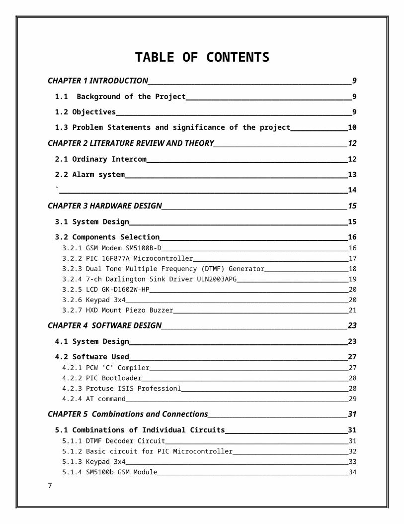
6.2.1 Voltage divider_______________________________________________________________________386.2.2 Fbus and Mbus_______________________________________________________________________396.2.3 USB Host Shield______________________________________________________________________406.2.4 GSM Module________________________________________________________________________43
CHAPTER 7 Discussion and Conclusion_____________________________________________45
7.1 Problems We Faced______________________________________________________________45
7.2 Future improvement_____________________________________________________________47
7.3 Conclusion_____________________________________________________________________48
7.4 Commercial Study_______________________________________________________________49
Appendix_____________________________________________________________________50
Appendix A: GSM MODEM___________________________________________________________50
Appendix B: PIC 16F877A_____________________________________________________________52
Appendix C: MAX 232_______________________________________________________________53
Appendix D: ULN2003_______________________________________________________________54
Appendix E: DTMF Decoder___________________________________________________________55
Appendix F: LCD____________________________________________________________________56
References___________________________________________________________________57
7
CHAPTER 1INTRODUCTION
1.1 Background of the Project 1.2 Objectives 1.3 Problem Statements and significance of the project
8

CHAPTER 1 INTRODUCTION
1.1 Background of the Project
This project is aimed at designing GSM door intercom that able to make a call to a specific hand phone when any one come to home and pressed a switch button. The increasing of the number of the stealing and house breaking cases especially when the people are not at home, need a system that can tell them if anyone trying to breaking home by enter not acceptable numbers for many times. By using AT command in our software program, a call can be made to the owner cheaply and easily without need to an extra expensive telecommunication system. The project which powered by 5V battery is made of a cheap PIC Microcontroller, DTMF decoder, keypad, LCD, switches and GSM modem. The project that would minimize the stealing cases either at homes, shops and offices will be a great deal and desirable for the potential buyers. It would be intercom + security system.
1.2 Objectives
To study the modem language (AT commands) and calling system. To study the Dual Tone Multi Frequency (DTMF) tones generator theory. To design the DTMF tones generator using software and C++ language. To design digital door lock. To design the Keypad pressed number generator using software and C++
language. Implement the AT command that able to make a call to a specific number
using PIC Microcontroller and corresponding circuit from GSM modem when any visitor come to home or when there is a thief want to breaking home by access the door using password. In addition you will receive a message when any one enters your home using ID.
9

1.3 Problem Statements and significance of the project
Nowadays, the only ordinary intercom which just open the door by an element internal the home is not sufficient at all; since many visitors come when we outside. GSM door intercom will make a call to the owner mobile even though he is outside his home and there is a visitor also, the owner can open the door from any place in the world since it related to GSM network. Also bell alarm system is not sufficient since once the intruders the house, they can easily cut-off the system before the owners realize about that. So that, an alarm system that can immediately tell the owner is needed and it is very crucial for every house to have one. There are current existing systems that serve this objective, but due to the price not all people can have this at their home. The system of this project is cheap and easy to install since it used AT command as a language of the modem and make GSM modem to deal a specific number and to control the door remotely when the owner come to home by programmed a microcontroller to do all this.
10
CHAPTER 2LITERATURE REVIEW AND
THEORY
2.1 Ordinary Intercom
2.2 Alarm system
11
CHAPTER 2 LITERATURE REVIEW AND THEORY
2.1 Ordinary Intercom
Conventionally, the ordinary intercom which installed in our home, have the drawbacks of limited working range, that the owner should be inside the home to control the door lock. Use of a mobile phone for control the door can overcome these limitations. It provides many advantages, working range as large as the coverage area of the service provider, you can control the door lock from anywhere in the world. In this project, the door is controlled by GSM modem attached to the door that makes a call to the owner mobile phone. In the course of a call, if any button is pressed, a tone corresponding to the button pressed is heard at the other side of the call. This tone is called ‘dual-tone multiple-frequency’ (DTMF) tone. The pic microcontroller rceives this DTMF tone with the help of the modem stacked in the door. And when entering of numbers is finished, a compare will made by pic to make a decision for open the door or not.
In addition, when you forget your keys anywhere and you want to enter the home you can’t access the door without them!! In our project you can access it remotely without needing them just by enter the correct password.
Also you can know who enter your home all the day by received alarm message tell you that there is a person with specific ID enter your home, so if there is any crime happens, you can easily know who is it using messages you received in a specific time.
12

Fig 2.1a : The intercom inside the home Fig 2.1b : The same intercom with the front cover removed
2.2 Alarm system
Alarm system is a device that signals the occurrence of some undesirable event, normal alarm is not sufficient since once the intruders the house, they can easily cut-off the system before the owners realize about that. So that, an alarm system that can immediately tell the owner is needed and it is very crucial for every house to have one.
Our project provides this service with suitable cost that it can make a call immediately when anyone try to enter the home without permission of the owner by insert wrong keypad passwords.
13
`
CHAPTER 3HARDWARE DESIGN
3.1 System Design
3.2 Components Selection
3.2.1 GSM Modem SM5100B-D
3.2.2 PIC 16F877A Microcontroller
3.2.3 Dual Tone Multiple Frequency (DTMF) Generator
3.2.4 7-ch Darlington Sink Driver ULN2003APG
3.2.5 LCD GK-D1602W-HP
3.2.6 Keypad 3x4
3.2.7 HXD Mount Piezo Buzzer
14

CHAPTER 3 HARDWARE DESIGN
3.1 System Design
In conventional home Intercom system, the door lock is controlled by press a switch exist on the internal element of the intercom. In our project DTMF tones will be generated according to the mobile keypad pressing. The system or circuit in the telephone will recognize the pressing of the keypad button and generate the different DTMF tones. The combination of tones according to any password numbers go through DTMF decoder to microcontroller and open the door or not, but before that when a switch button is pressed outside the door microcontroller replace a call to a specific number which enter the password. In this project, the same concept will be used in order to make a call by a new way used for dialing. The project is based on the PIC Microcontroller in order to control all elements and component connect to it; DTMF decoder for mobile password, keypad for ID’s and passwords for many users, buzzer for alarm system, control circuit for the door lock (driver and solenoid) ,GSM modem attached to microcontroller using it as intercom (microphone, speaker and SIM card for AT command) and certain software (will be discussed in chapter four), the DTMF tones will be generated when any mobile switches is pressed. A buzzer was added in the system to give an
alarm signal if there any intrusion in the system to alarm people inside the home.
15
Fig 3.1: Block diagram for the whole system
3.2 Components Selection
We select suitable components taking into account they have features we need to implement our objectives.
3.2.1 GSM Modem SM5100B-D
GSM is widely used mobile communication architecture used in many projects and in most of the countries. This project used the interfacing of microcontroller with HyperTerminal and GSM module. It aims to familiarize with the syntax of AT Commands and their Information Response and Result Codes. HyperTerminal can be replaced by the microcontroller itself; thus avoiding the need of using a Computer to establish an interface, the controller itself sends a fixed AT command to the GSM module. The information response and result codes are received from GSM module. This would lead to an independent GSM based system.The microcontroller is programmed to receive and transmit data at a baud rate of 9600 with GSM module.
16
Fig 3.1: Interface between GSM module and microcontroller
3.2.2 PIC 16F877A Microcontroller
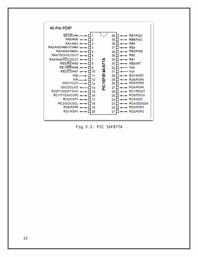
PIC 16F877, 8-bit microcontroller will be used for the controller. It was chosen to detect any switch triggered and analyzes the DTMF tones according to the predetermined hand phone number. This microcontroller has a 25 MHz processor (the current compiler runs the processor at 20 MHz), 33 input/output (I/O) pins, (8K*14words) of Enhanced FLASH program memory, (368*8bytes) of RAM, (256*8bytes) of data EEPROM. The PIC does not have an operating system and simply runs the program in its memory when it is turned on.
17
Fig 3.2: PIC 16F877A
18

3.2.3 Dual Tone Multiple Frequency (DTMF) Generator
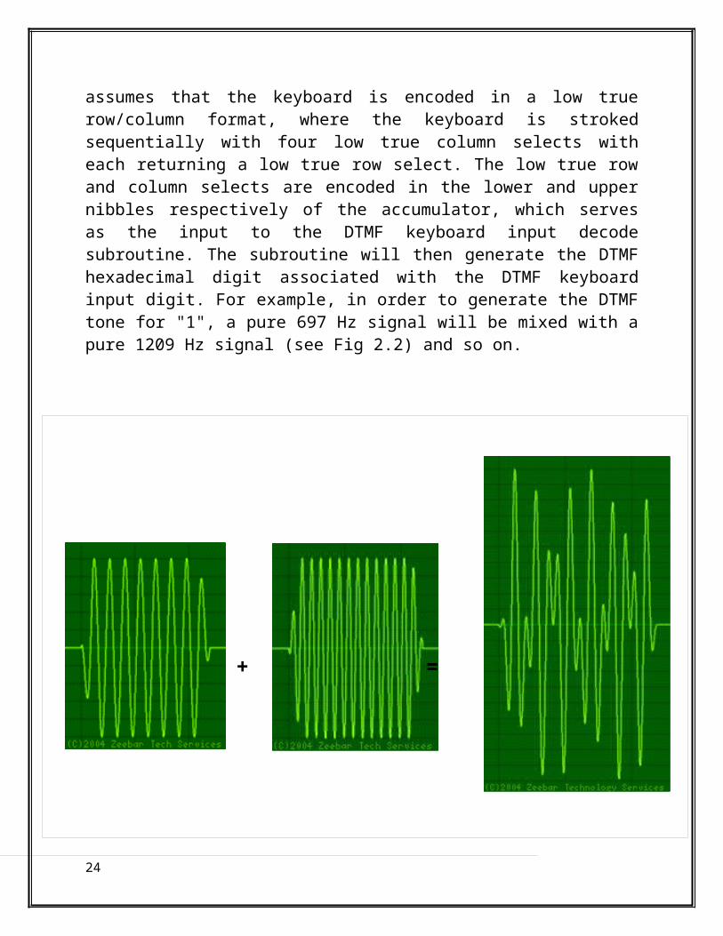
DTMF (figure 2.1) is associated with digital telephony, and provides two selected output frequencies (one high band, one low band) for a duration of 100 ms. DTMF generation consists of selecting and combining two audio tone frequencies associated with the rows (low band frequency) and columns (high band frequency) of a pushbutton touch tone telephone keypad. The low band frequencies are 697 Hz, 770 Hz, 852 Hz, and 941 Hz, while the high band frequencies are 1209 Hz, 1336 Hz, 1477 Hz, and 1633 Hz . The matrix for selecting the high and low band frequencies associated with each key is shown in Figure 2.2.
Fig 3.3a The DTMF IC Fig 3.3b The DTMF frequencies and
corresponding keys
Each key is uniquely referenced by selecting one of the four low band frequencies associated with the matrix rows, coupled with selecting one of the four high band frequencies associated with the matrix columns. The DTMF keyboard input decode 10 subroutine assumes that the keyboard is encoded in a low true row/column format, where the keyboard is stroked sequentially with four low true column selects with each returning a low true row select. The low true row and column selects are encoded in the lower and upper nibbles respectively of the accumulator, which serves as the input to the DTMF keyboard input decode subroutine. The subroutine will then generate the DTMF hexadecimal digit associated with the DTMF keyboard input digit. For example, in order to generate the DTMF tone for "1", a pure 697 Hz signal will be mixed with a pure 1209 Hz signal (see Fig 2.2) and so on.
19
+ =
697 HZ + 1209 HZ = “1”
Fig 3.3c Two Pure Sine Waves combine to form the DTMF Tone for "1"
3.2.4 7-ch Darlington Sink Driver ULN2003APG
The ULN2003APG/AFWG Series are high−voltage, high−current Darlington drivers comprised of seven NPN Darlington pairs. All units feature integral clamp diodes for switching inductive loads. Applications include relay, hammer, lamp and display (LED) drivers.
20
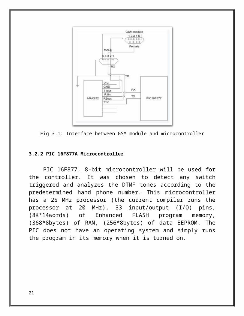
Fig3.4: 7-ch Darlington Sink Driver ULN2003APG
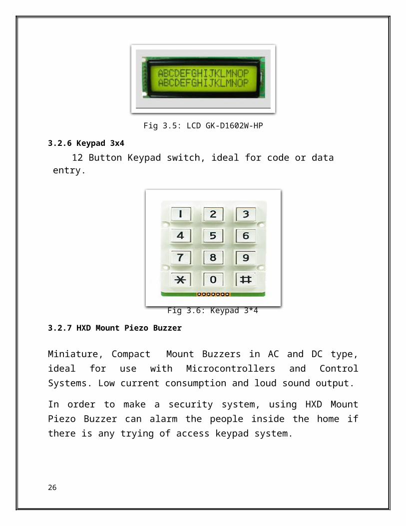
3.2.5 LCD GK-D1602W-HP
Using to display characters and show the output of operations that happened in the system.
Fig 3.5: LCD GK-D1602W-HP
3.2.6 Keypad 3x4
12 Button Keypad switch, ideal for code or data entry.
Fig 3.6: Keypad 3*4
21
3.2.7 HXD Mount Piezo Buzzer
Miniature, Compact Mount Buzzers in AC and DC type, ideal for use with Microcontrollers and Control Systems. Low current consumption and loud sound output.
In order to make a security system, using HXD Mount Piezo Buzzer can alarm the people inside the home if there is any trying of access keypad system.
Fig 3.7: HXD Mount Piezo Buzzer
22

CHAPTER 4SOFTWARE DESIGN
4.1 System Design
4.2 Software Used
4.2.1 PCW 'C' Compiler
4.2.2 PIC Bootloader
4.2.3 Protuse ISIS Professional
4.2.4 AT command
CHAPTER 4 SOFTWARE DESIGN
4.1 System Design 23
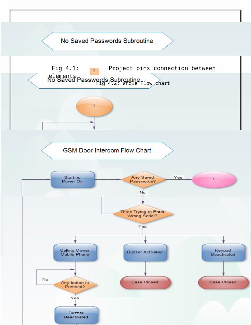
Figures (4.2, 4.3 and 4.4) show flowcharts of the whole programming structure of GSM door intercom and how the system works.
The software is written in ‘C’ language and compiled using Code Vision PCW 'C' compiler. The source program is converted into hex code by the compiler. Burn this hex code into pic 16f877A microcontroller. The source program is well commented and easy to understand.
The following diagram shows the all connection which was drawn by protuse.
Fig 4.1: Project pins connection between elementsFig 4.2: Whole Flow chart
24
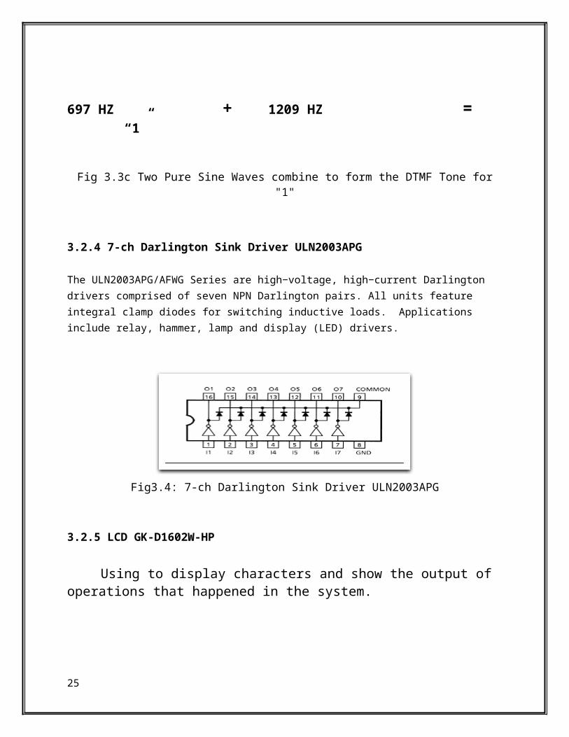
Fig 4.4: Saved passwords subroutine
25
4.2 Software Used
The software is written in ‘C’ language and compiled using Code Vision PCW 'C' compiler. The source program is converted into hex code by the compiler. Burn this hex code into pic 16f877A microcontroller. The source program is well commented and easy to understand.
4.2.1 PCW 'C' Compiler
This software is being used to design and write the programming code of the project in C++ language. The code then will be compiled to generate the hex file to be burn into the PIC Microcontroller. One of the advantages of this compiler is to provide higher level programming for designer to solve their errors which appears in the code.
Fig 4.4: PCW 'C' Compiler
26
4.2.2 PIC Bootloader
This software is being used to download the hex file of the source code into PIC Microcontroller. It also has a window to display the output of the code. Fig 4.5
Fig 4.5: Bootloader
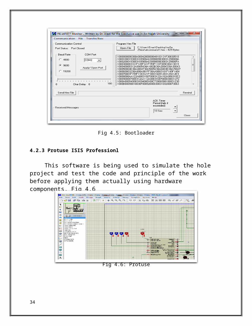
4.2.3 Protuse ISIS Professionl
This software is being used to simulate the hole project and test the code and principle of the work before applying them actually using hardware components. Fig 4.6
Fig 4.6: Protuse
27
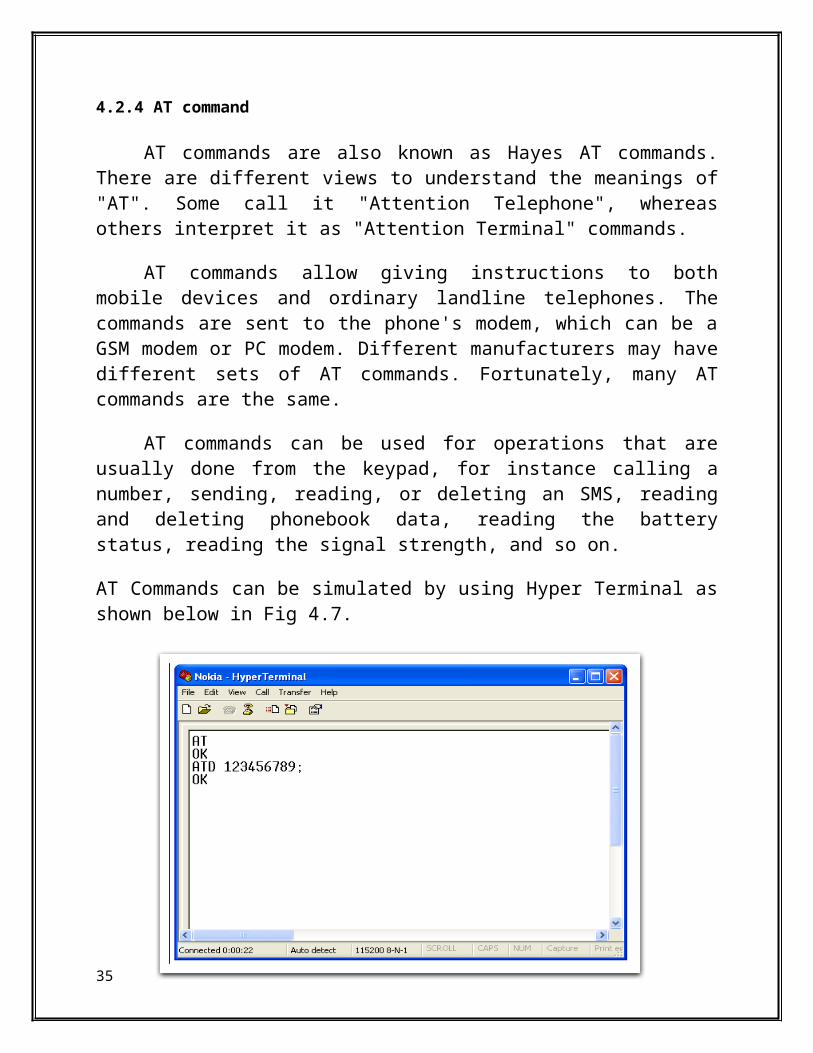
4.2.4 AT command
AT commands are also known as Hayes AT commands. There are different views to understand the meanings of "AT". Some call it "Attention Telephone", whereas others interpret it as "Attention Terminal" commands.
AT commands allow giving instructions to both mobile devices and ordinary landline telephones. The commands are sent to the phone's modem, which can be a GSM modem or PC modem. Different manufacturers may have different sets of AT commands. Fortunately, many AT commands are the same.
AT commands can be used for operations that are usually done from the keypad, for instance calling a number, sending, reading, or deleting an SMS, reading and deleting phonebook data, reading the battery status, reading the signal strength, and so on.
AT Commands can be simulated by using Hyper Terminal as shown below in Fig 4.7.
Fig 4.7: Applying AT command on a hyper terminal program
28
CHAPTER 5Combinations and Connections
5.1 Combinations of Individual Circuits
5.1.1 DTMF Decoder Circuit
5.1.2 Basic circuit for PIC Microcontroller
5.1.3 Keypad 3x4
5.1.4 SM5100b GSM Module
5.2 Connections between Circuits
CHAPTER 5 Combinations and Connections
29
5.1 Combinations of Individual Circuits
Connect each circuit alone to test them before make the hole circuit to ensure that they work correctly.
5.1.1 DTMF Decoder Circuit
Build DTMF Decoder is the first step in the system, which can analyze the mobile signal and convert it into binary one, in other words the decoder uses digital counting techniques to detect and decode all 16 DTMF tone-pairs into a 4-bit code, then it sends the output digital signal to Pic microcontroller. In our case we connected GSM module with DTMF Decoder but in the first trying to check the DTMF Decoder circuit we connected it with a Mobile, as we will see in chapter six.
Fig 5.1: DTMF Decoder circuit
5.1.2 Basic circuit for PIC Microcontroller
Basic circuit make an easy connection between Pic microcontroller and other components in the system, also it makes the download of software on Pic by PC more easier to send/receive data to/from, but PCs modem don't have a serial port so we need a USB to serial converter.
30
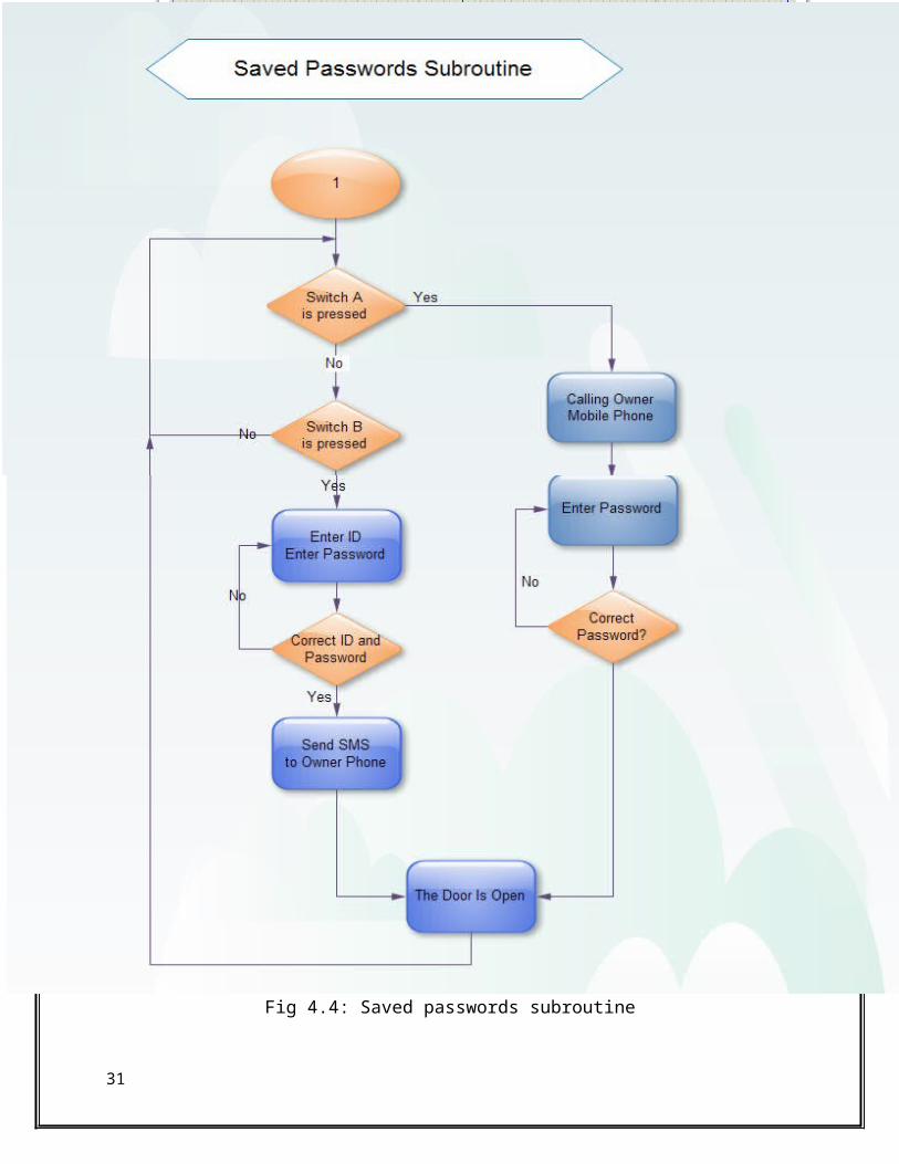
Fig 5.2: Interface between PC and PIC using serial cable
In Serial Communication the line that is used to transmit data is called Tx and the line used to receive data is called Rx. The PIC MCU uses TTL level for logic that is a 1 is a 5v and 0 is 0v but RS232 standard uses different scheme for logic level.
Fig 5.3: The basic circuit
5.1.3 Keypad 3x4
In order to insert an ID and Password of the intercom, keypad connection was needed to work this properly; the inserted key will be analyzed by Pic microcontroller which connected with Keypad.
31
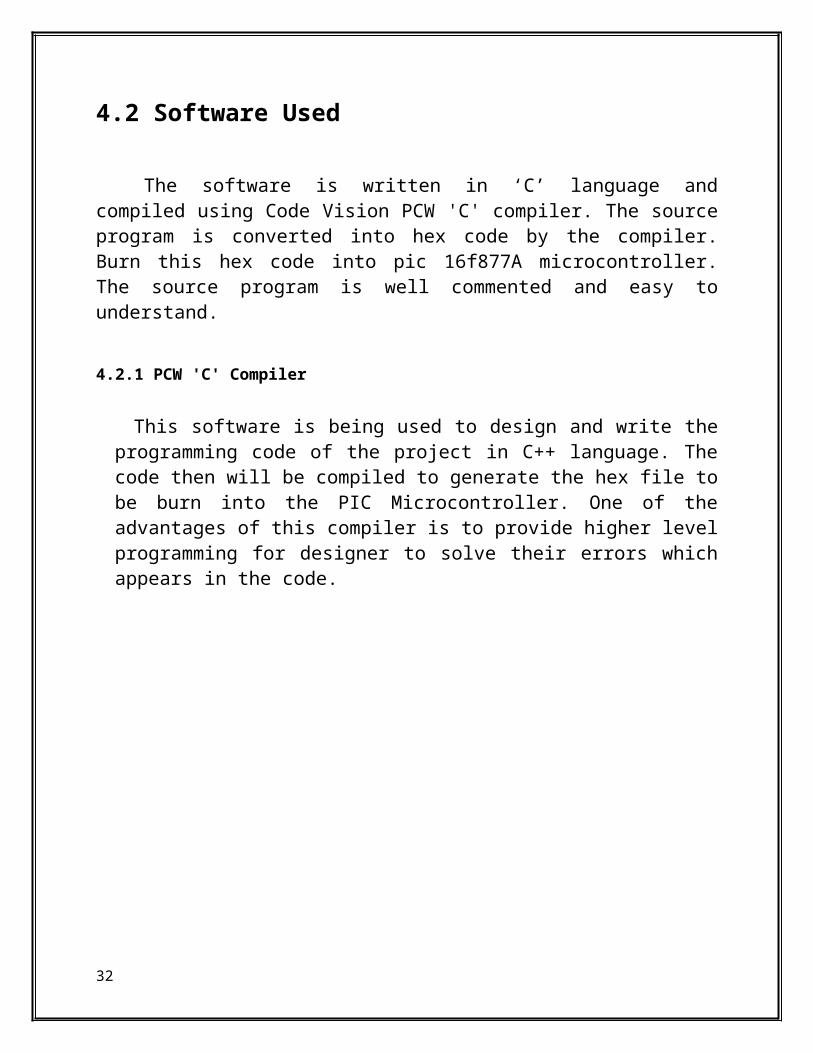
Table 1: output arrangement of keypad Fig 5.4a: circuit diagram of keypad
Fig 5.4b: Keypad in the system
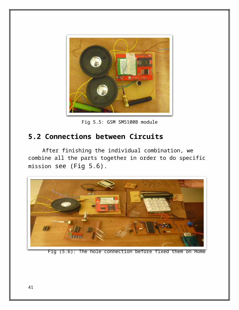
5.1.4 SM5100b GSM Module
In our project we connected SM5100b GSM module with basic circuit, microphone, speaker and DTMF Decoder.
32
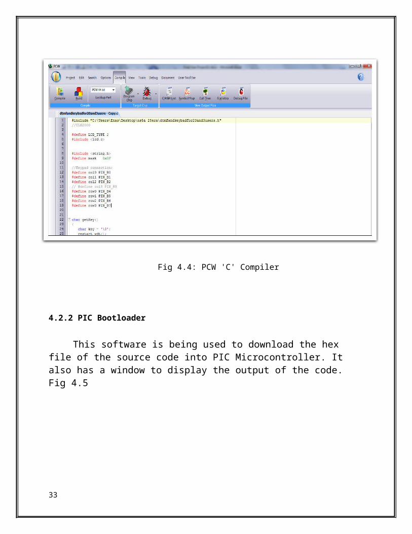
Fig 5.5: GSM SM5100B module
5.2 Connections between Circuits
After finishing the individual combination, we combine all the parts together in order to do specific mission see (Fig 5.6).
Fig (5.6): The hole connection before fixed them on Home
33
CHAPTER 6Compact Report
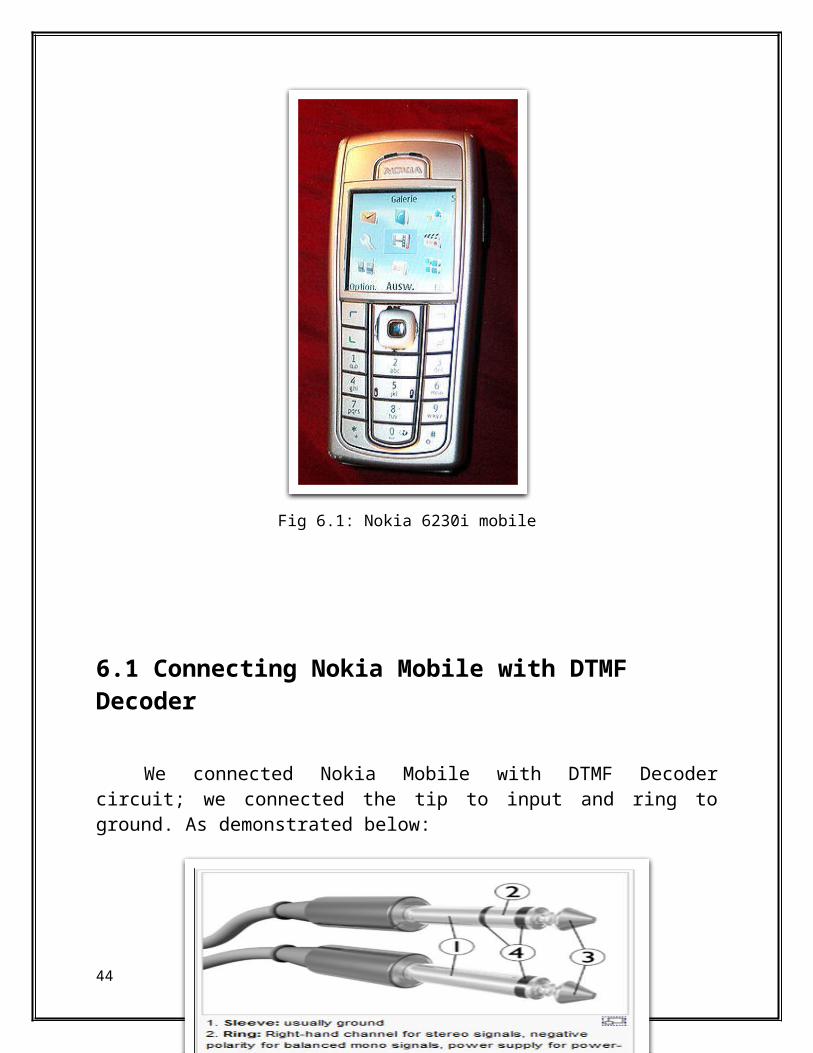
*Our System with Nokia 6230i*
6.1 Connecting Nokia Mobile with DTMF Decoder
6.2 Connecting Nokia Mobile with Pic Microcontroller
6.2.1 Voltage divider
6.2.2 Fbus and Mbus
6.2.3 USB Host Shield
6.2.4 GSM Module
CHAPTER 6 Compact report (Our System with Nokia 6230i )
We studied the AT command with Nokia 6230i Mobile, also we connected the mobile with DTMF Decoder and it worked correctly. Our choice of choosing Mobile phone is due to its low cost and its internal modem which supports AT Commands that we need to use in our project. But when we reached the step of
34
joining the Pic with Nokia Mobile we found that this connection is complicated and not sufficient, so we decided to replace it with GSM Module ; and the next sections in this chapter discuss the methods of connecting mobile with pic microcontroller.
Fig 6.1: Nokia 6230i mobile
6.1 Connecting Nokia Mobile with DTMF Decoder
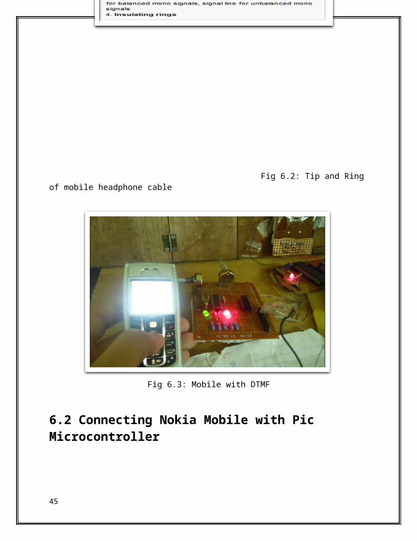
We connected Nokia Mobile with DTMF Decoder circuit; we connected the tip to input and ring to ground. As demonstrated below:
35
Fig 6.2: Tip and Ring of mobile headphone cable
Fig 6.3: Mobile with DTMF
6.2 Connecting Nokia Mobile with Pic Microcontroller
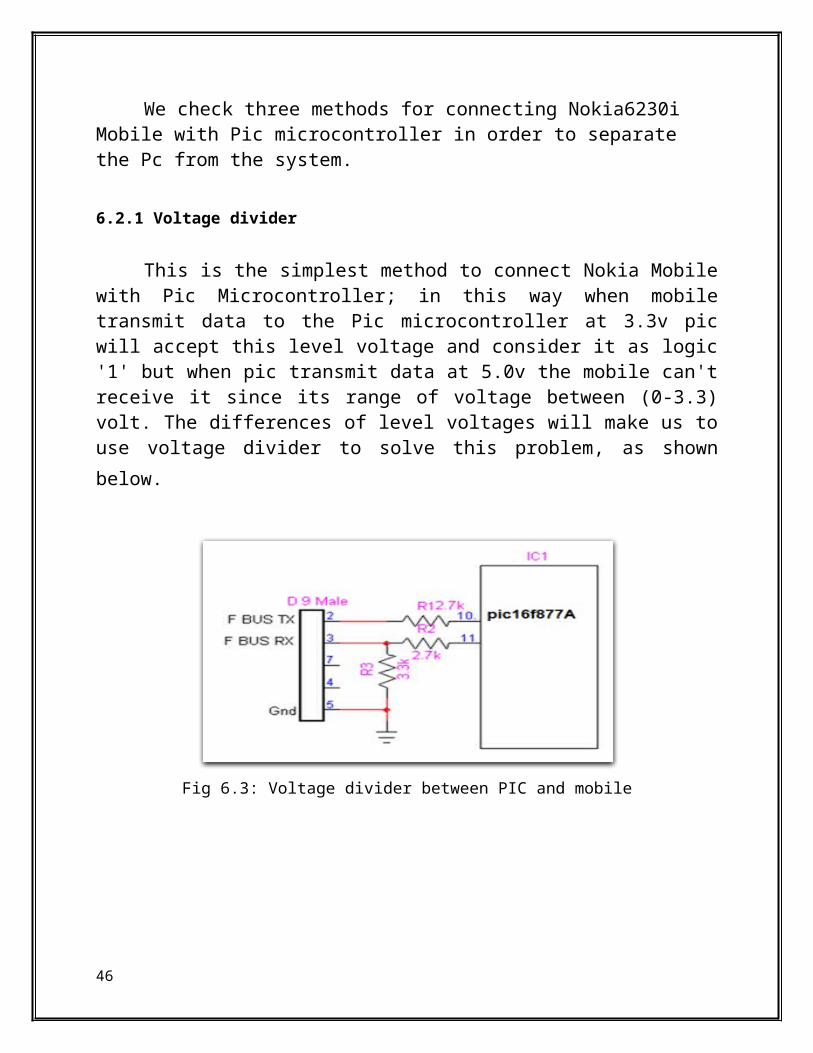
We check three methods for connecting Nokia6230i Mobile with Pic microcontroller in order to separate the Pc from the system.
6.2.1 Voltage divider
36
This is the simplest method to connect Nokia Mobile with Pic Microcontroller; in this way when mobile transmit data to the Pic microcontroller at 3.3v pic will accept this level voltage and consider it as logic '1' but when pic transmit data at 5.0v the mobile can't receive it since its range of voltage between (0-3.3) volt. The differences of level voltages will make us to use voltage divider to solve this problem, as shown below.
Fig 6.3: Voltage divider between PIC and mobile
6.2.2 Fbus and Mbus
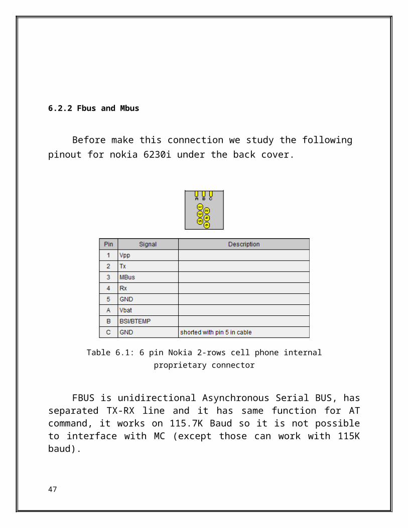
Before make this connection we study the following pinout for nokia 6230i under the back cover.
37
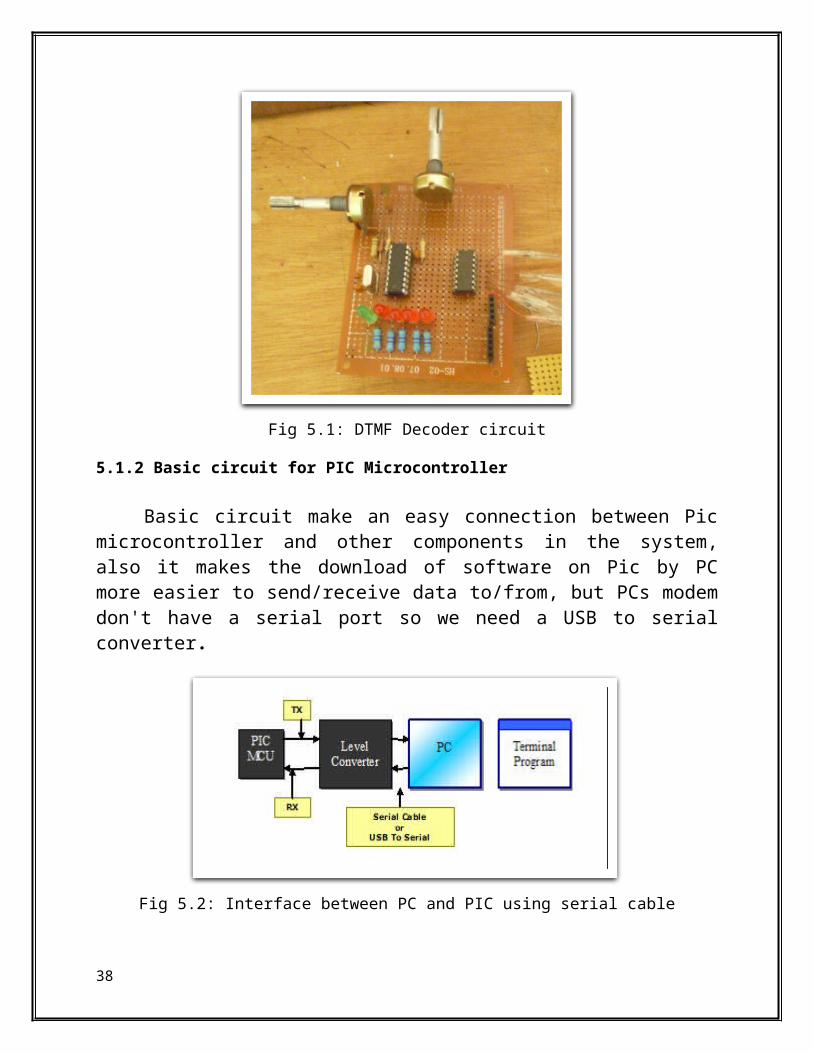
Table 6.1: 6 pin Nokia 2-rows cell phone internal proprietary connector
FBUS is unidirectional Asynchronous Serial BUS, has separated TX-RX line and it has same function for AT command, it works on 115.7K Baud so it is not possible to interface with MC (except those can work with 115K baud).
Phones with no modem don't support AT Commands. They work on FBUS protocol. MBUS is bi-direction Asynchronous Serial BUS, multiplexed TX-RX line. See Fig (6.4)
38

Fig 6.4: Connect Mobile Using FBUS Method
6.2.3 USB Host Shield
First of all we studied the external pop port pin out of Nokia 6230i Mobile and how to connect these pins to pic microcontroller by USB cable so we decided to replace pic 16 with pic 18 since it does not has USB pins (D+ and D-).
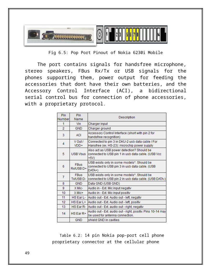
Fig 6.5: Pop Port Pinout of Nokia 6230i Mobile
The port contains signals for handsfree microphone, stereo speakers, FBus Rx/Tx or USB signals for the phones supporting them, power output for feeding the accessories that dont have their own batteries, and the Accessory Control Interface (ACI), a bidirectional serial control bus for connection of phone accessories, with a proprietary protocol.
39
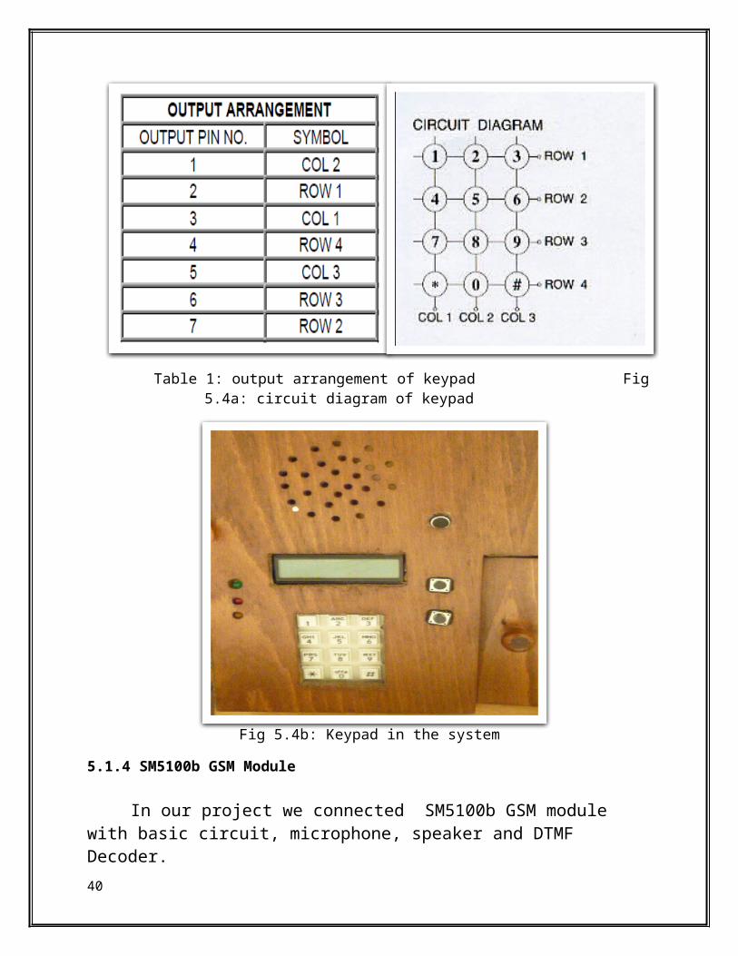
Table 6.2: 14 pin Nokia pop-port cell phone proprietary connector at the cellular phone
The PIC18FX455/X550 device family contains a full-speed and low-speed compatible USB Serial Interface Engine (SIE) that allows fast communication between any USB host and the PIC microcontroller. The SIE can be interfaced directly to the USB, utilizing the internal transceiver, or it can be connected through an external transceiver. An internal 3.3V regulator is also available to power the internal transceiver in 5V applications.
But unfortunately mobile phone cannot consider as USB host so we need a connection point between it and pic 18 microcontroller, after a hard search we found this connection point which is USB Host shield.
USB Host shield converts from USB (D+ and D-) to serial (Tx and Rx) so that there is no need to use pic 18 microcontroller. The shield exists in configurations compatible with 5V and 3.3V Arduino boards. Modern phones have
40
standard GSM chip interface implemented and accessible via so-called "data port". The oldest phones implement TTL level asynchronous serial interface by means of "custom" USB data cable, which is just proprietary connector on one end, standard USB connector on the other end, and USB-to-serial converter chip between them. Newer cell phones have USB-to-serial converter built-in.
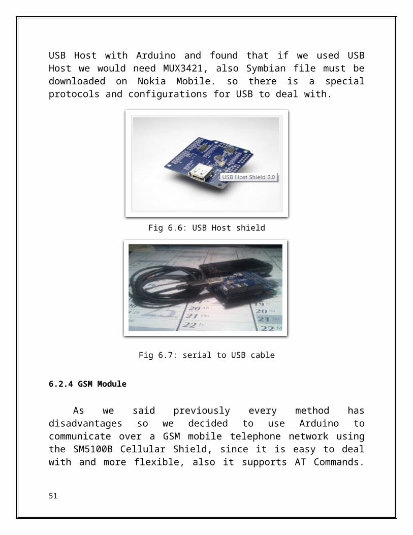
In our case we need to get the mobile phone talking with arduino and USB Host shield through cable and connecting them to pic microcontroller. When we studied USB Host with Arduino and found that if we used USB Host we would need MUX3421, also Symbian file must be downloaded on Nokia Mobile. so there is a special protocols and configurations for USB to deal with.
Fig 6.6: USB Host shield
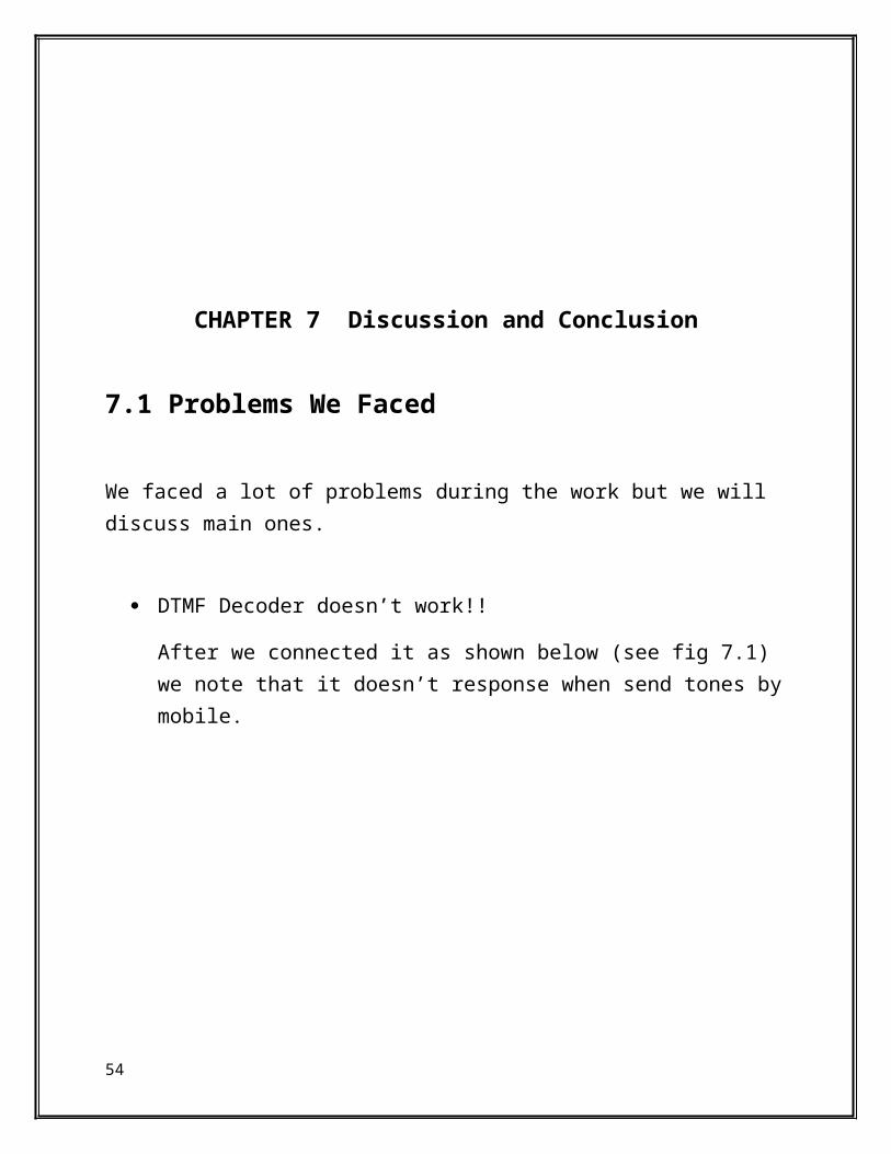
Fig 6.7: serial to USB cable
6.2.4 GSM Module
41
As we said previously every method has disadvantages so we decided to use Arduino to communicate over a GSM mobile telephone network using the SM5100B Cellular Shield, since it is easy to deal with and more flexible, also it supports AT Commands. It has unlimited transmission range and distance, so we can use it in any place.
GSM can easily send and receive data across the mobile network, and it can transmit instructions or commands or receive them from Pic microcontroller. More specifically, within the scope of this article we will do so mainly using text or SMS messages.
Fig 6.8: GSM modem
GSM Features
1. Range - unlimited2. 2 way speech (full duplex) .3. 2 x Volt free relays momentary output to control automatic gates or door
lock.4. Easy to use.5. Check reception by SMS text.6. Easy programming by DTMF on any telephone handset, or SMS text.
42

CHAPTER 7Discussion and Conclusion
7.1 Problems we Faced
7.2 Future improvement
7.3 Conclusion
7.4 Commercial Study
CHAPTER 7 Discussion and Conclusion
43
7.1 Problems We Faced
We faced a lot of problems during the work but we will discuss main ones.
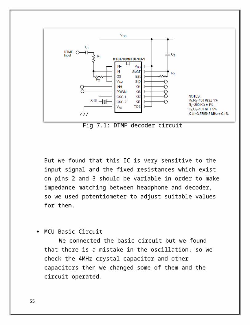
DTMF Decoder doesn’t work!!
After we connected it as shown below (see fig 7.1) we note that it doesn’t response when send tones by mobile.
Fig 7.1: DTMF decoder circuit
But we found that this IC is very sensitive to the input signal and the fixed resistances which exist on pins 2 and 3 should be variable in order to make impedance matching between headphone and decoder, so we used potentiometer to adjust suitable values for them.
MCU Basic Circuit
44
We connected the basic circuit but we found that there is a mistake in the oscillation, so we check the 4MHz crystal capacitor and other capacitors then we changed some of them and the circuit operated.
LCD GK-D1602W-HP After we connected LCD to pic as shown in its datasheet, it didn’t
display anything so we solved this problem by using 2KΩ variable resistor and adjust it.
Power supply gave 5 + .2v Some elements need exactly 5v like GSM module, so the solution that
we must check the power supply and ensure that it gives 5volt.
7.2 Future improvement
Access the Door by sending a message
We will improve our project by open the door using a message which can be analyzed by Microcontroller.
Change saved password by sending a message
45
In the future we can program the pic microcontroller to compare the received password with saved password and set the new password which is sent in the same message.
Sensors
We can add many sensors as safety alarms Sensors which can be associated with intercom and a response device. The most common security sensors indicate the opening of a door or window or detect motion.
Video Intercom
We can use a camera and connect it with our project to capture a picture for any person comes to home and send this picture for the owner using GSM modem.
46
7.3 Conclusion
In conclusion, it can be claimed that the project of GSM Door intercom with keypad and security system provide benefits in improving the ordinary intercom. By only 5V battery, low-cost PIC Microcontroller and other circuit, this system can be applied at any houses, offices or shops as long as they need a security system to protect their possession. The size of this project can be reduced by design the PCB (printed circuit board) of the PIC and the corresponding circuit in the smallest way.
47

7.4 Commercial Study
In our project we tried to use elements which has more needed functionality with high efficiency and minimum cost. The lest below shows the cost of each component used in the project.
Name of element Cost (NIS)DTMF Decoder MT8870D 10GSM Modem SM5100B-D 500
LCD Wh1602DYGK 50Pic16f877A 40
7 HXD Mount Piezo Buzzer 5Keypad 3x4 25
MUX232 5Serial Cable 35
solenoid 20Driver ULN2003 6
Other Components 120 Total cost 816
48
Appendix
Appendix A: GSM MODEM
49
50
Appendix B: PIC 16F877A
51

Appendix C: MAX 232
52

Appendix D: ULN2003
53
Appendix E: DTMF Decoder
54
Appendix F: LCD
55
References
Websites:
1.http://en.wikipedia.org/wiki/; June 2009.
Books:
1. Advanced PIC Microcontroller Projects in C-Dogan Ibrahim London, 2007
2. PIC16F877A, module by module, interfacing and programming using C, with many examples and projects - Ahmed Ihmeid
3. IEEE 802.15.4.4 – Homepage, The Institute of Electrical and Electronics Engineers, Inc., February 2007, http://www.ieee802.org/15/pub/TG4.html IEEE 802.15.2 Standard
56