Embed Size (px)
Citation preview

A Software of Generating a Symbolic Circuit Model withComputers for Wireless Power Transmission System
Takuya HirataDepartment of Materials and Informatics
Interdisciplinary Graduate Schoolof Agriculture and Engineering
University of Miyazaki1-1, Gakuen-kibanadai-nishiMiyazaki 889-2192 Japan
Yuta YamamotoDepartment of Materials and Informatics
Interdisciplinary Graduate Schoolof Agriculture and Engineering
University of Miyazaki1-1, Gakuen-ibanadai-nishiMiyazaki 889-2192 Japan
Kazuya YamaguchiDepartment of Materials and Informatics
Interdisciplinary Graduate Schoolof Agriculture and Engineering
University of Miyazaki1-1, Gakuen-kibanadai-nishiMiyazaki 889-2192 Japan
Ichijo HodakaDepartment of Environmental Robotics
School of EngineeringUniversity of Miyazaki
1-1, Gakuen-kibanadai-nishiMiyazaki 889-2192 Japan
Abstract:Conventional researches on Wireless Power Transmission systems use experimental or numerical methodto analyze the systems. However, the situation will be better if symbolic method is available. This paper developsa software which generates a state equation directly from schematics. The software helps engineers that designcircuits and obtain characteristics of circuits to analyze the behavior of circuits with circuit parameters by symboliccomputing. Our software also provides various perspectives of the system with circuit parameters.
Key–Words:symbolic circuit analysis, modelling, power transfer
1 IntroductionThere are numerous number of products poweredby electric power in the world, such as mobilephones, cars, computers and televisions — the heart ofthose products is electric circuits which are proposed,tested, and fabricated by circuit engineers. Nowadays,the design process is dominated by circuit numericalsimulators such as SPICE, a de facto standard tool inacademia as well as industry. Using SPICE, engineersand designers can analyze the circuits which may con-tain nonlinear elements such as diodes and transistors,and any complex circuits supposing real electric partsin the time and frequency domains. Circuit engineersdesign their circuits with deep consideration of howthe circuit parameters will affect the outputs of the cir-cuits. Since the consideration sums up the results fromeach value of parameters, they need to repeat manysets of numerical simulation on SPICE. On the otherhand, it is obvious that if their circuit is simple enoughto write equations they will be able to understand thewhole behavior of the circuit. In this situation, they
have symbolic equations which govern the behaviorof the circuits in terms of voltages and currents. How-ever, it is also true that such a symbolic analysis isnot popular in practical use. One reason for it is thatcomputer aided tools available now with symbolic ex-pressions are less sophisticated than SPICE. A sym-bolic solution to practical circuits are very difficult tofind due to an explosion of computation steps as thenumber of elements increase. Even if the symbolicsolution is found, it tends to be too complicated tobe interpret by engineers. Some of these problemshave been handled by recent studies[1]-[5], but otherproblems have been still open, and engineers continueto use SPICE. However, there are some researches oncircuits with symbolic analysis[7][8].
The heart of a wireless power transfer system withmagnetic resonance is to transmit much electric powerwith high efficiency to the loads in the secondary froma voltage source in the primary. The system is real-ized by the circuits which is composed of resistors,inductors, and capacitors, thus, linear circuits. The
WSEAS TRANSACTIONS on CIRCUITS and SYSTEMSTakuya Hirata, Yuta Yamamoto, Kazuya Yamaguchi, Ichijo Hodaka
E-ISSN: 2224-266X 266 Volume 13, 2014

efficiency and quantity of the transfer power are dif-ferent among different circuits. Additionally, the wayto design the circuits which can transmit the powermaximally is not established. Thus we have to designmany circuits and compare the circuits from the pointof view of efficiency and the quantity of the power.
In this paper, we propose the method to automat-ically make circuit models which express the wire-less power transmission behavior from a primary cir-cuit to a secondary circuit. The model is expressedin so-called state equation fully embedded with sym-bols of the value of electrical elements as well as volt-ages and currents in the circuit. Some of conven-tional software[4][6] does not handle wireless situa-tion. The software which can compute wireless cir-cuit equations are based on transfer functions. Sinceour algorithm outputs a state equation instead of trans-fer functions, one has a benefit: we can utilize othersophisticated computation tools seamlessly with ouralgorithm, and apply theoretical idea arranged and de-veloped on a state equation in other academic field.
2 Proposed MethodIn general circuit equations which represent the be-havior of provided circuits are composed of KVL(Kirchhoff’s Voltage Law), KCL (Kirchhoff’s CurrentLaw) and Laws which are voltage and current law ofthe elements. We consider here that a circuit is com-posed of resistors, inductors, capacitors and a voltagesource. Then circuit equations are written by lineardifferential equations and linear algebraic equations.The circuit equations contain variables (function oftime) – each of voltages and currents –representingcircuit states. In these equations, there areredundantquantities, voltage and current of resistors, current ofcapacitors and voltage sources, voltage of inductorsand nodes.
We call circuit equations which contain the redun-dant quantities and redundant circuit equations. Addi-tionally, we call circuit equations which are expressedas a linear combination of only independent quanti-tiesnon-redundantcircuit equations. In this paper, wepropose a method which is suitable for a computer al-gorithm and is to transform redundant circuit equa-tions into non-redundant circuit equations systemati-cally.
Linear differential equations in redundant circuitequations are written as
z = Fx (1)
wherez is a vector which arranges vertically voltageof inductors and current of capacitors.x is a vec-tor which arranges vertically current of inductors and
voltage of capacitors. A matrixF is determined byxconsistency.
Algebraic equations in redundant circuit equa-tions can be written as (2) after eliminating voltageand current of resistors, current of a voltage source,voltage of nodes.
K1z +K2x+K3u = 0 (2)
whereu is the voltage of a voltage source. The matri-cesK1, K2, K3 are determined consistently byz, x,u respectively.
We define a matrixQ as the following.
Q =[K1 K2 K3
](3)
If rankQ = r, then we can transform (2) into thefollowing.
z = −(KT1 K1)
−1KT1 (K2x+K3u) (4)
Even if rankQ = r, we can transformQ into theform rankQ = r after we eliminate linearly depen-dent rows ofQ.
By using (1), ifdetF = 0, we can rewrite (4) asthe following.
x = −F−1(KT1 K1)
−1KT1 (K2)x
−F−1(KT1 K1)
−1KT1 (K2)u (5)
If we put
A = −F−1(KT1 K1)
−1KT1 (K2) (6)
B = −F−1(KT1 K1)
−1KT1 (K3), (7)
then (5) can be rewritten as
x = Ax+Bu (8)
and we obtain non-redundant circuit equations. ThematricesA andB contain symbolic inversion of ma-trices. Generally, larger size matrices require longertime of computation. Thus, we found a way of be-ing illustrated Figure 1 in a process of eliminatingvoltage and current of resistors, current of a voltagesource, voltage of nodes in redundant circuit equa-tions. Hereby, we can perform the computing witha little computational effort.
2.1 Implementation
Our proposed method is described in a flowchart ofFigure 1.
WSEAS TRANSACTIONS on CIRCUITS and SYSTEMSTakuya Hirata, Yuta Yamamoto, Kazuya Yamaguchi, Ichijo Hodaka
E-ISSN: 2224-266X 267 Volume 13, 2014
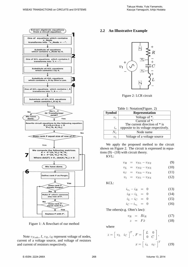
Figure 1:A flowchart of our method
NotevNode, I, vR, iR represent voltage of nodes,current of a voltage source, and voltage of resistorsand current of resistors respectively.
2.2 An Illustrative Example
Figure 2:LCR circuit
Table 1: Notation(Figure. 2)Symbol Representation
v∗ Voltageof *.
i∗
Current of*.The current direction of * is
opposite to its voltage respectively.N∗ Node namev1 Voltageof a voltage source
We apply the proposed method to the circuitshown on Figure 2. The circuit is expressed in equa-tions (9) - (18) with circuit theory.
KVL:
vR = vN1 − vN2 (9)
vL = vN2 − vN3 (10)
vC = vN3 − vN4 (11)
v1 = vN1 − vN4 (12)
KCL:
iv1 − iR = 0 (13)
iR − iL = 0 (14)
iL − iC = 0 (15)
iC − iv1 = 0 (16)
The others(e.g. Ohm’s law):
vR = RiR (17)
z = Fx (18)
where
z =[vL iC
]T, F =
[L 00 C
],
x =[iL vC
]T(19)
WSEAS TRANSACTIONS on CIRCUITS and SYSTEMSTakuya Hirata, Yuta Yamamoto, Kazuya Yamaguchi, Ichijo Hodaka
E-ISSN: 2224-266X 268 Volume 13, 2014

First, weapply the step 1 in Figure 1 to (9) - (12).KVL:
v1 = vR + vL + vC (20)
Second, we apply the step 2 in Figure 1 to (13) -(16).
KCL:
iC − iR = 0 (21)
iR − iL = 0 (22)
iL − iC = 0 (23)
Third, we apply the step 3 in Figure 1 to (20).KVL:
v1 = RiR + vL + vC (24)
Next, we apply the step 4 in Figure 1 to (20).KCL:
iC − iL = 0 (25)
iL − iC = 0 (26)
KVL:
v1 = RiC + vL + vC (27)
Next, We apply the step 5 in Figure 1 to (25)-(27).
P =
0 1 −1 0 00 −1 1 0 0
−1 −R 0 −1 0
(28)
SincerankP = 3 = 2, next we apply the step 6in Figure 1 toP .
P =
[0 −1 1 0 0
−1 −R 0 −1 0
](29)
Finally, we can findA, B by calculating the equa-tions shown on the step 7 in Figure 1.
A =
[−R
L−1L
1C 0
], B =
[1L0
](30)
where
K1 =
[0 −1
−1 −R
], K2 =
[1 00 −1
],
K3 =
[01
]. (31)
3 A Transformer Model for WirelessTransfer
As a model for receiving and transmitting coils ofa wireless power transfer, we consider that there are(n− 1) loads in the secondary windings in the modelon Figure 3.
Transmitter
(Primary Coil)
Receiver 1st
Receiver nth
(Secondary Coils)
.....
+
--
+
--+
--
Figure 3: A transformer model for a wireless powertransfer system
By Neumann’s law, we can write the mutual in-ductorM in the following equation[10]-[12].
Mij =µ0
4π
∮Ci
∮Cj
dli · dljrij
(32)
where1 ≤ i ≤ n, 1 ≤ j ≤ n, asi = j,Mij representsLi. Ci andCj representthe path around Coili andCoil j respectively.dli anddlj show vectors of Coili and Coilj respectively.rij represents the distancebetween Coili and Coilj. A mutual inductanceMij isdetermined by the distance between coils and a shapeof a coil(the number of turns) and so on.
We can consider that a model of a transmissioncoil and a receiver coil is in the case of a variable mu-tual inductanceMij by a distance between coils and arelative position of a coil in a general electric circuit.Hence we adopt the relation expression between volt-age and current in an ideal transformer in the case ofthe variable mutual inductanceMij as the model for awireless power transfer.
v = Hi (33)
where v, i are v =[v1 v2 . . . vn
]T, i =[
i1 i2 . . . vn]T
, respectively and
WSEAS TRANSACTIONS on CIRCUITS and SYSTEMSTakuya Hirata, Yuta Yamamoto, Kazuya Yamaguchi, Ichijo Hodaka
E-ISSN: 2224-266X 269 Volume 13, 2014

H =L1 ±M12 ±M13 . . . ±M1n
±M21 L2 ±M23 . . . ±M2n...
......
......
±Mn1 ±Mn2 . . . ±Mnn−1 Ln
. (34)
4 An Example of Analyzing a WPTCircuit with Proposed Algorithm
+
+
+ +
+ +
-
++
+-
-
-
- - - -
-
Figure 4:Wireless power transfer circuit
Table 2: Notation(Figure. 4)Symbol Representation
v1 Voltageof a voltage sourceR1, R2,R3, R4 Resistor
L1, L2
Coil(Inductor)The windingdirection ofL1 isthe same as the direction ofL2.
C1, C2 Capacitorv∗ Voltageof *
i∗
Current of*The current direction of * is
opposite to its voltage respectively.
We consider a wireless power transfer systemshown on Figure 4 which consists of a circuit that iscomposed of resistors, inductors(including coils), ca-pacitors and a voltage source. Thus, we can make amodel by proposed method and by use the model, wecan analyze an effect of power transfer by variationof circuit parameters. This modelling is performed byWasabi that we implement our proposed method as acomputer program.
x = Ax+Bu (35)
A =
0 0 1
C10
0 0 0 1C2
−L2∆
M12∆
(−R1−R2)L2
∆(R4+R3)M12
∆M21∆
−L1∆
(R1+R2)M21
∆(−R4−R3)L1
∆
(36)
B =
00L2∆
−M21∆
(37)
x =[vC1 vC2 iL1 iL2
]T(38)
u = v1 (39)
where∆ = L2L1 −M12M21. The other symbols arerepresented in Table 2.
In this system, by using symbols that are an av-erage powerP4 of a load resistorR4 and an averagepowerP1 of a voltage source, including an internal re-sistance, we can write an efficiencyη as the following.
η =
∣∣∣∣∣ P4
P1
∣∣∣∣∣ (40)
If we choosev1 which is the voltage of a voltagesource forv1(t) = sin(ωt), then we can write the ef-ficiencyη as
η =C22M
212R4ω
4
α(41)
where
α = |C22M12M21(R3 +R4)ω
4
+R2(1− 2C2L2ω2 +
C22ω
2(R23 + 2R3R4 +R2
4 + L22ω
2))|(42)
andω, t are angular frequency, time respectively. Notethe obtained equation is complicated, but we cananalyze the efficiency by leaving symbolic parame-ters that we are only interested in. This is possi-ble since the model as expressed in symbolic equa-tions. Next we introduce concretely similar situationthrough some examples.
4.1 A Case of Only a Variation ofM12 andM21
By (32), mutual inductancesM12 andM21 vary witha distance between the primary coilL1 and the sec-ondary coilL2. Thus, if we would like to analyzethat how the distance effects the efficiency, then we re-gard (40) as a function about the mutual inductances.For example, letM12 = M21 = M and letM bea variable. We consider the case of varying with0.01L1 ≤ M ≤ 0.1L1 by changing the distance.
WSEAS TRANSACTIONS on CIRCUITS and SYSTEMSTakuya Hirata, Yuta Yamamoto, Kazuya Yamaguchi, Ichijo Hodaka
E-ISSN: 2224-266X 270 Volume 13, 2014
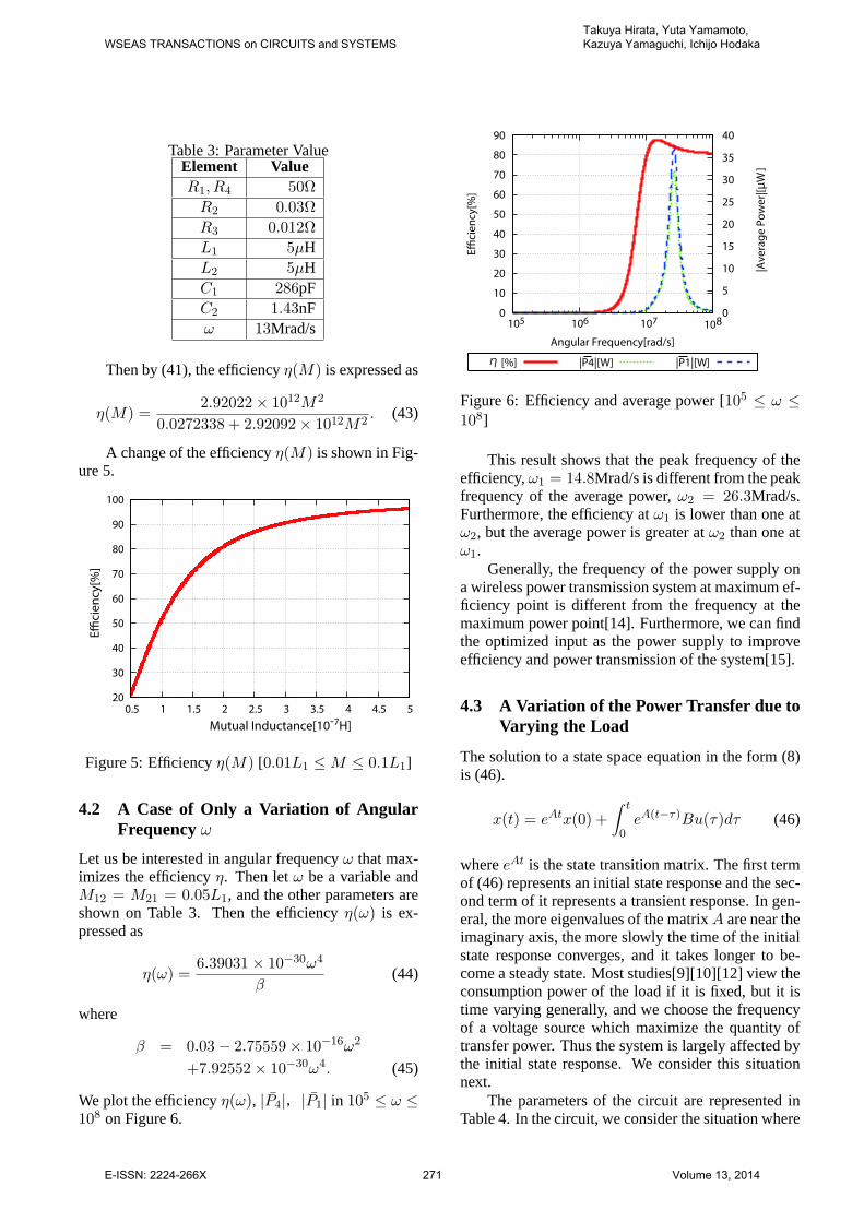
Table3: Parameter ValueElement ValueR1, R4 50Ω
R2 0.03Ω
R3 0.012Ω
L1 5µHL2 5µHC1 286pFC2 1.43nFω 13Mrad/s
Then by(41), the efficiencyη(M) is expressed as
η(M) =2.92022× 10¹²M2
0.0272338 + 2.92092× 10¹²M2. (43)
A change of the efficiencyη(M) is shown in Fig-ure 5.
20
30
40
50
60
70
80
90
100
0.5 1 1.5 2 2.5 3 3.5 4 4.5 5
Eciency[%
]
M utual Inductance[10-7H ]
Figure 5:Efficiencyη(M) [0.01L1 ≤ M ≤ 0.1L1]
4.2 A Case of Only a Variation of AngularFrequencyω
Let us be interested in angular frequencyω that max-imizes the efficiencyη. Then letω be a variable andM12 = M21 = 0.05L1, and the other parameters areshown on Table 3. Then the efficiencyη(ω) is ex-pressed as
η(ω) =6.39031× 10⁻³⁰ω4
β(44)
where
β = 0.03− 2.75559× 10⁻¹⁶ω2
+7.92552× 10⁻³⁰ω4. (45)
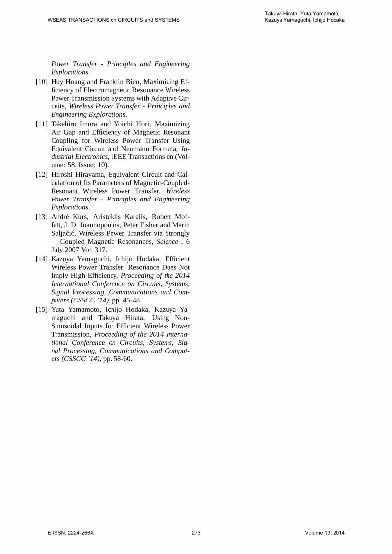
We plot the efficiencyη(ω), |P4|,|P1| in 105 ≤ ω ≤108 on Figure 6.
0
10
20
30
40
50
60
70
80
90
105 106 107108
0
5
10
15
20
25
30
35
40
E
cie
ncy
[%]
|Av
era
ge
Po
we
r|[µ
W]
Angular Frequency[rad/s]
] |P4|[W] |P1|[W]η
Figure 6:Efficiency and average power [105 ≤ ω ≤108]
This result shows that the peak frequency of theefficiency,ω1 = 14.8Mrad/s is different from the peakfrequency of the average power,ω2 = 26.3Mrad/s.Furthermore, the efficiency atω1 is lower than one atω2, but the average power is greater atω2 than one atω1.
Generally, the frequency of the power supply ona wireless power transmission system at maximum ef-ficiency point is different from the frequency at themaximum power point[14]. Furthermore, we can findthe optimized input as the power supply to improveefficiency and power transmission of the system[15].
4.3 A Variation of the Power Transfer due toVarying the Load
The solution to a state space equation in the form (8)is (46).
x(t) = eAtx(0) +
∫ t
0eA(t−τ)Bu(τ)dτ (46)
whereeAt is the state transition matrix. The first termof (46) represents an initial state response and the sec-ond term of it represents a transient response. In gen-eral, the more eigenvalues of the matrixA are near theimaginary axis, the more slowly the time of the initialstate response converges, and it takes longer to be-come a steady state. Most studies[9][10][12] view theconsumption power of the load if it is fixed, but it istime varying generally, and we choose the frequencyof a voltage source which maximize the quantity oftransfer power. Thus the system is largely affected bythe initial state response. We consider this situationnext.
The parameters of the circuit are represented inTable 4. In the circuit, we consider the situation where
WSEAS TRANSACTIONS on CIRCUITS and SYSTEMSTakuya Hirata, Yuta Yamamoto, Kazuya Yamaguchi, Ichijo Hodaka
E-ISSN: 2224-266X 271 Volume 13, 2014

Table4: Parameter ValueElement ValueL1, L2 50mH
R1 50Ω
R2 0.03Ω
R3 0.012Ω
M12,M21 0.05L1
C1 2.86µFC2 14.3µFω 2.5krad/s
the resistanceR4 changesfrom R4 = 50[Ω] to R4 =49[Ω] at t = 0.3[s] where the initial statex(0) = 0.
Figure 7:Response ofP4
It takes0.3s to get the steady state from0s. At0.3s, the load resistorR4 varies to49Ω, and it takes0.01s to get the steady state again. After all, in0.4s,it takes0.31s and the average power only expresses inthe power if a steady state has remained since0s, thus,there is an extra estimation about the load power.
5 ConclusionIn wireless power transfer, we must search a suitablefrequency of a voltage source for high efficiency andhigh power supplying capability. We have proposeda method of circuit modelling automatically for com-puting the suitable frequency and the efficiency. Wedefine a model a transfer model between the coilsfor wireless power transfer and we have been able toanalyze more circuit through simplifying the processwhich makes models for searching high efficiency cir-cuits.
We have shown that we can analyze the behaviorof circuits with leaving the symbolic parameters thatwe interested in since models are expressed in sym-bolic equations. We have confirmed the achievementof these objects by our proposed method.
In this paper, we have been able to reduce thecomputing time of analysis of circuits, and analyzecircuits if the circuit topology is large and the circuitis composed of many elements, and as a consequence,we have been able to search suitable circuits for wire-less power transfer systems more widely.
References:
[1] Hassoun, M. M. and Lin, P. M. , A hierarchicalnetwork approach to symbolic analysis of large-scale networks,Circuits and Systems I: Funda-mental Theory and Applications, IEEE Transac-tions on (Volume: 42,Issue: 4).
[2] Starzyk, J. A.and Konczykowska, A. , Flow-graph analysis of large electronic networks,Cir-cuits and Systems, IEEE Transactions on (Vol-ume: 33, Issue: 3).
[3] Xiang-Dong Tan and C. J. Richard Shi, Hierar-chical Symbolic Analysis of Analog IntegratedCircuits via Determinant Decision Diagrams,Computer-Aided Design of Integrated Circuitsand Systems, IEEE Transactions on(Volume:19, Issue: 4 April 2000).
[4] C. J. Richard Shi and Xiang-Dong Tan, Canon-ical Symbolic Analysis of Large Analog Cir-cuits with Determinant Decision Diagrams,Computer-Aided Design of Integrated Circuitsand Systems, IEEE Transactions on(Volume:19, Issue: 1 January 2000).
[5] A. MOUHRI, A. RAHMANI and G.DAUPHIN-TANGUY, Symbolic Determi-nation of Generalized State Equation forSingular System Modelled by Bond Graph,CSCC’99 Proceedings, pp.2811-2816.
[6] Luchetta, A., Manetti, S., Reatti, A., SAPWIN-a symbolic simulator as a support in electricalengineering education,Education, IEEE Trans-actions on (Volume:44 , Issue: 2 ).
[7] Zdenek Kolka, Dalibor Biolek, Viera Biolkova,Symbolic Analysis of Linear Circuits with Mod-ern Active Elements,WSEAS TRANSACTIONSon ELECTRONICS(Issue 6, Volume 5, June2008).
[8] Eko Setiawan, Ichijo Hodaka, Yuta Yamamoto,Symbolic Analysis of Maximizing Efficiency ofPhotovoltaic Power Generation Circuits,LatestAdvances in Systems Science and ComputationalIntelligencepp. 49-52.
[9] Alexey Bodrov and Seung-Ki Sul, Analysisof Wireless Power Transfer by Coupled ModeTheory (CMT) and Practical Considerations toIncrease Power Transfer Efficiency,Wireless
WSEAS TRANSACTIONS on CIRCUITS and SYSTEMSTakuya Hirata, Yuta Yamamoto, Kazuya Yamaguchi, Ichijo Hodaka
E-ISSN: 2224-266X 272 Volume 13, 2014
Power Transfer - Principles and EngineeringExplorations.
[10] Huy Hoang and Franklin Bien, Maximizing Ef-ficiency of Electromagnetic Resonance WirelessPower Transmission Systems with Adaptive Cir-cuits, Wireless Power Transfer - Principles andEngineering Explorations.
[11] Takehiro Imura and Yoichi Hori, MaximizingAir Gap and Efficiency of Magnetic ResonantCoupling for Wireless Power Transfer UsingEquivalent Circuit and Neumann Formula,In-dustrial Electronics, IEEE Transactions on (Vol-ume: 58, Issue: 10).
[12] Hiroshi Hirayama, Equivalent Circuit and Cal-culation of Its Parameters of Magnetic-Coupled-Resonant Wireless Power Transfer,WirelessPower Transfer - Principles and EngineeringExplorations.
[13] Andre Kurs, Aristeidis Karalis, Robert Mof-fatt, J. D. Joannopoulos, Peter Fisher and MarinSoljacic, Wireless Power Transfer via Strongly Coupled Magnetic Resonances,Science, 6July 2007 Vol. 317.
[14] Kazuya Yamaguchi, Ichijo Hodaka, EfficientWireless Power Transfer Resonance Does NotImply High Efficiency,Proceeding of the 2014International Conference on Circuits, Systems,Signal Processing, Communications and Com-puters (CSSCC ’14), pp. 45-48.
[15] Yuta Yamamoto, Ichijo Hodaka, Kazuya Ya-maguchi and Takuya Hirata, Using Non-Sinusoidal Inputs for Efficient Wireless PowerTransmission,Proceeding of the 2014 Interna-tional Conference on Circuits, Systems, Sig-nal Processing, Communications and Comput-ers (CSSCC ’14), pp. 58-60.
WSEAS TRANSACTIONS on CIRCUITS and SYSTEMSTakuya Hirata, Yuta Yamamoto, Kazuya Yamaguchi, Ichijo Hodaka
E-ISSN: 2224-266X 273 Volume 13, 2014