Embed Size (px)
Citation preview
A Study on the Influence of Steel, Slag or Gas on Refractory Reactions
Sune Jansson
Doctoral Thesis
Stockholm 2008
Department of Material Science and Engineering Division of Applied Process Metallurgy
Royal Institute of Technology SE-100 44 Stockholm
Sweden
Akademisk avhandling som med tillstånd av Kungliga Tekniska Högskolan i Stockholm, framlägges för offentlig granskning för avläggande av Teknologie Doktorsexamen, måndagen den 2 juni 2008, kl. 13.00 i B2, Brinellvägen 23, Kungliga Tekniska Högskolan, Stockholm
ISRN KTH/MSE--08/14--SE+APRMETU/AVH
ISBN 978-91-7415-007-0

2
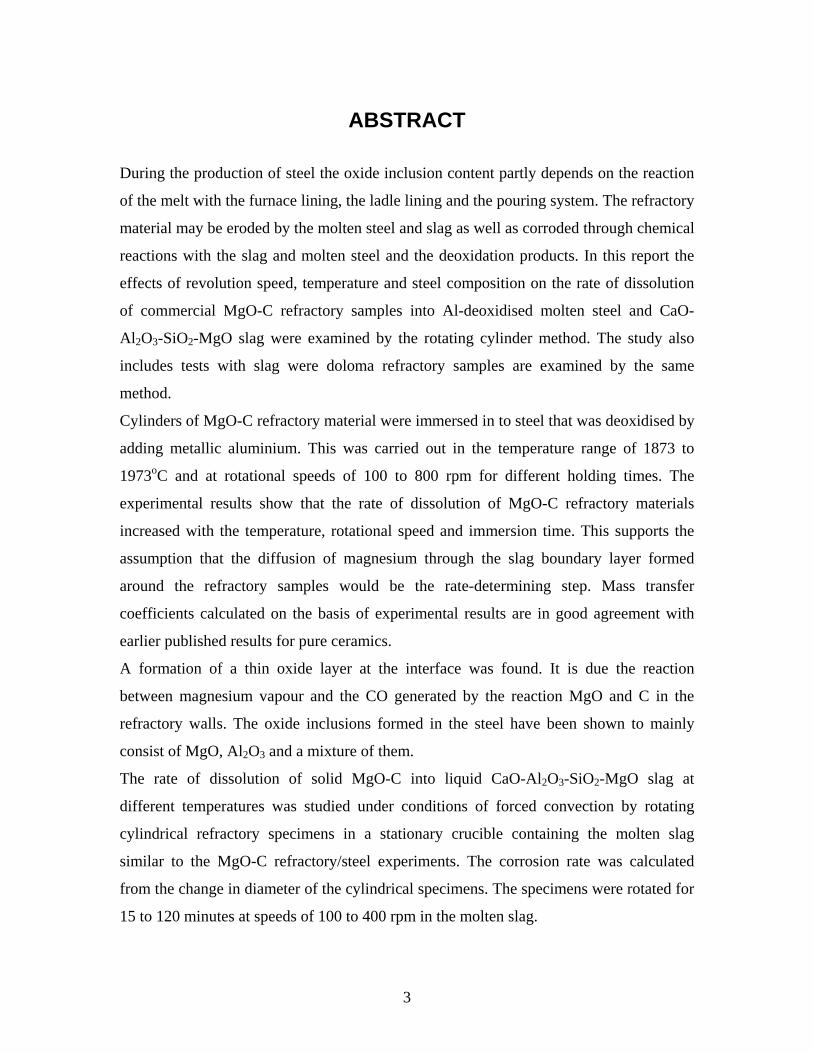
ABSTRACT
During the production of steel the oxide inclusion content partly depends on the reaction
of the melt with the furnace lining, the ladle lining and the pouring system. The refractory
material may be eroded by the molten steel and slag as well as corroded through chemical
reactions with the slag and molten steel and the deoxidation products. In this report the
effects of revolution speed, temperature and steel composition on the rate of dissolution
of commercial MgO-C refractory samples into Al-deoxidised molten steel and CaO-
Al2O3-SiO2-MgO slag were examined by the rotating cylinder method. The study also
includes tests with slag were doloma refractory samples are examined by the same
method.
Cylinders of MgO-C refractory material were immersed in to steel that was deoxidised by
adding metallic aluminium. This was carried out in the temperature range of 1873 to
1973oC and at rotational speeds of 100 to 800 rpm for different holding times. The
experimental results show that the rate of dissolution of MgO-C refractory materials
increased with the temperature, rotational speed and immersion time. This supports the
assumption that the diffusion of magnesium through the slag boundary layer formed
around the refractory samples would be the rate-determining step. Mass transfer
coefficients calculated on the basis of experimental results are in good agreement with
earlier published results for pure ceramics.
A formation of a thin oxide layer at the interface was found. It is due the reaction
between magnesium vapour and the CO generated by the reaction MgO and C in the
refractory walls. The oxide inclusions formed in the steel have been shown to mainly
consist of MgO, Al2O3 and a mixture of them.
The rate of dissolution of solid MgO-C into liquid CaO-Al2O3-SiO2-MgO slag at
different temperatures was studied under conditions of forced convection by rotating
cylindrical refractory specimens in a stationary crucible containing the molten slag
similar to the MgO-C refractory/steel experiments. The corrosion rate was calculated
from the change in diameter of the cylindrical specimens. The specimens were rotated for
15 to 120 minutes at speeds of 100 to 400 rpm in the molten slag.
3
The rate of corrosion increased with temperature and with rotating speed of the rod and
decreased when the slag was nearly saturated with MgO. The experimental results
confirm the assumption that the diffusion of magnesium oxide through the slag phase
boundary layer controls the corrosion process. The corrosion mechanism seems to be the
dissolution of elements in the refractory materials into the slag, followed by penetration
into the pores and grain boundaries. Finally, grains are loosened from the refractory into
the slag.
The investigation of doloma and doloma-carbon showed that the dissolution of magnesia
into the slag was determining the corrosion rate. As for the other experiments,
steel/MgO-C refractory and slag/MgO-C refractory, the corrosion rate was calculated
from the change in diameter of the cylindrical specimens. The specimens were rotated for
15 to 120 minutes at speeds of 100 to 400 rpm in the molten slag. The results from the
study showed that refractory materials that were impregnated with carbon had a much
better slag resistance than the refractory that contained no carbon. This is due to the
higher wetting angle between carbon and slag.
Corrosion of MgO-C refractories in different gas atmospheres consisting of air, Ar, CO
or Ar/CO was also studied. Experiments were carried out in the temperature range 1173
K to 1773 K and for holding times between 2 to 120 min. The reaction rate of the MgO-C
material was determined from measurements of the weight loss of the samples. The
results showed that the refractory weight loss increased with an increased temperature or
an increased holding time. The thermodynamic conditions and the experimental results
show that magnesium gas and carbon monoxide gas should form during ladle refining of
steel when the refractory material consists of MgO-C.
4
ACKNOWLEDGEMENTS First, and most of all, I would like to thank my supervisor Professor Voicu Brabie, for giving me the opportunity to work with this project. It has been a lot of hard work and some time less of sleep, but still it has been very pleasant and instructive. I would like to thank him for his excellent guidance, encouragement and help during this work. Much of this work is his own ideas, so if it was not for him, this work may not have been done. I am also very grateful to my other supervisor Professor Pär Jönsson. I will make special thanks to him for constant support and inspiration during these years. Without his help the work would be much difficult. Whenever I needed his guidance, he has taken his time to listen to me so we could together solve whatever was necessary. The Swedish School of Mining and Metallurgy, Bergsskolan, has been like a second home to me for lot of years. So I would like to express a special thanks to all the colleagues and friends at Bergsskolan. Special thanks to my research assistants Adam Hylén, Lars Bohlin, Jenny Karlsson, Susanne Stude and Jörgen Andersson. The personnel at the analysis laboratory at Dalarna University are thanked for all the help that they have done for my work and me during the years. There have been a lot of hours in the laboratory using the SEM/EDS equipment. Colleagues and friends at The Royal Institute of Technology, KTH, are acknowledged. Financial supports for this work from The Swedish Steel Producers Association, Jernkontoret, are gratefully acknowledged. The financial support from Arvika Gjuteri AB during the writing of the thesis is gratefully acknowledged. The personnel at Sandvik Steel AB, Uddeholm Tooling AB, Scana Steel Björneborg AB and Höganäs Halmstadsverken are thanked for support of material and analysis during the work. I would like to thank my mother and father for their unlimited moral support and understanding. I also thank them for the financial support during these years of study. Finally, I would like to thank my wife Anne for the support and understanding and to my two boys Patrik and Alexander for their tolerance for my work. Arvika, May 2008
Sune Jansson
5

6
SUPPLEMENTS The present thesis is based on the following papers: Supplement 1: “Magnesia-carbon refractory dissolution in Al killed low carbon
steel”
S. Jansson, V. Brabie and P. Jönsson.
Published: Ironmaking and Steelmaking, October 2006, Volume 33, Number 5, pp 389-397.
Supplement 2: “Corrosion mechanism and kinetic behaviour of MgO-C refractory
material in contact with CaO-Al2O3-SiO2-MgO slag”
S. Jansson, V. Brabie and P. Jönsson.
Published: Scandinavian Journal of Metallurgy, October 2005, Volume 34, Number 5, pp 283-292.
Supplement 3: “Corrosion mechanism of commercial doloma refractories in
contact with CaO-Al2O3-SiO2-MgO slag”
S. Jansson, V. Brabie and P. Jönsson.
Published: Ironmaking and Steelmaking, February 2008, Volume 35, Number 2, pp 99-107.
Supplement 4: “Corrosion mechanism of commercial MgO-C refractories in
contact with different gas atmospheres”
S. Jansson, V. Brabie and P. Jönsson.
Published: ISIJ International, June 2008, Volume 48, Number 6, pp 766-773.
7

8
Parts of this work have been presented at the following conferences:
I. S. Jansson and V. Brabie, “Corrosion mechanism and kinetic behaviour of refractory materials in contact with CaO-Al2O3-MgO-SiO2 slags”, Nordic Symposium for Young Scientists, Production Metallurgy for Iron, Steel and Ferroalloys, 11-13 June 2003, Oulu, Finland.
II. S. Jansson, V. Brabie and L. Bohlin, “Corrosion mechanism and kinetic behaviour of refractory materials in contact with CaO-Al2O3-MgO-SiO2 slags”, VII International Conference on Molten Slags, Fluxes and Salts, 25-28 January 2004, Cape Town, South Africa.
III. S. Jansson and V. Brabie, ”Upplösning av keramik i CaO-MgO-aluminatslagger – mekanismer och kinetik”, STÅL 2004, 5-7 May 2004, Borlänge, Sweden.
IV. S. Jansson, “Astudy on reactions between MgO-C refractory material and gas atmospheres during ladle refining of steel”, Second Nordic Symposium for Young Scientist in Metallurgy, 22-23 March 2006, Stockholm, Sweden.
Publication not included in this thesis:
Å. Jansson, V. Brabie, E. Fabo, and S. Jansson, “Slag formation and its role in the ferrochromium production”, Scandinavian Journal of Metallurgy, October 2002, Volume 31, Number 5, pp 314-320.
9

10
CONTENTS
ABSTRACT 3
ACKNOWLEDGEMENTS 5
SUPPLEMENTS 7
CONTENTS 11
1. INTRODUCTION 13
2. THEORETICAL ASPECTS 16 2.1. Thermodynamics 16 2.2. Kinetics 22
3. EXPERIMENTAL METHODS 30 3.1. Reactions between refractory and steel, (S1) 30
3.1.1. Materials 30 3.1.2. Experimental set-up 31
3.2. Reactions between refractory and slag, (S2 and S3) 33 3.2.1. Materials 33 3.2.2. Experimental set-up 34
3.3. Reactions between refractory and gas, (S4) 35 3.3.1. Materials 35 3.3.2. Experimental set-up 35
4. EXPERIMENTAL RESULTS 38 4.1. Reaction between MgO-C refractory and molten steel, (S1) 38 4.2. Reaction between MgO-C refractory and molten slag, (S2) 40 4.3. Reaction between doloma refractory and molten slag, (S3) 43 4.4. Reaction between MgO-C refractory and gas, (S4) 47
5. DISCUSSION 50 5.1. The effect of temperature on the dissolution rate 52 5.2. The effect of the revolution speed on the dissolution rate 53 5.3. Formation of inclusions in steel 54 5.4. Formation of an oxide layer at the steel/refractory interface 55 5.5. Penetration of slag into the refractory material 56 5.6. The effect of slag composition on the dissolution rate 58 5.7. The influence of the gas atmosphere on the weight loss 59 5.8. The influence of oxide layers on the reaction rate at gas/refractory interface 59
6. CONCLUSIONS 61
7. FUTURE WORK 64
8. REFERENCES 65
11

12
1. INTRODUCTION
This work summaries some aspects on how the refractory material in the ladle interacts
with steel, slag and gas during steel refining. Refractory materials consist of chemically
stable non-metallic compounds or a mixture of them. Properties such as a good heat
resistance and a high hardness make them suitable for use as linings in steelmaking
ladles. However, the conditions during the steel refining processes are aggressive, which
makes the ceramics susceptible to corrosion. This together with their brittle nature gives
limitation to their applicability. Here, it should be noted that the life length of the
refractories depends on the strength and porosity of the refractory material.
The dissolution of solid oxides into molten slag is related to ladle life, slag formation and
the absorption of non-metallic inclusions by mould flux in continuous casting. Therefore,
the clarification of the dissolution behavior of solid oxides into molten slag is an
important issue in refining and casting processes. In recent years, the use of materials
composed of more than one refractory component for improvement of the durability of
bricks tends to increase. In order to clarify the dissolution behavior of such composite
materials, it may be necessary to understand the dissolution mechanism and kinetics of
each component.
At the same time, numerous experiments [1-5] have shown that there is a clear evidence of
interaction between liquid steel and refractory materials that is dependent on both the
steel composition and the type of refractory material. Therefore, the reactions that
transfer elements between the refractories and molten steel are closely related to the
product quality.
It is well known that non-metallic inclusions could form inside the steel or is descended
from external sources like refractory bricks, slag or alloying materials. Theirs
composition and size are directly depended of steel, slag or ceramic materials
13
compositions. Thus, when the molten steel is treated in a ladle, the reaction between steel
and the refractory lining have a great influence on the steel cleanliness.
The resistance to chemical corrosion of the refractory materials can be improved by
selecting materials with a better thermodynamic stability or by generating kinetic
diffusion barriers that decreases the propagation of the corrosion reaction. These areas
require fundamental understanding of thermodynamics, kinetics and mass transfer aspects
of the reactions involved.
Today, many steel plants use magnesia or doloma refractories with a carbon content of
between 5 and 20 wt-% as ladle refractory lining nearest the molten steel and slag. The
function of the carbon is to fill out the porous structure and to prevent the slag to
penetrate into the pores. One explanation to this is that the wetting angle between slag
and graphite is big and that a dense layer of MgO and CO is formed, which hinders the
slag penetration.
This work is mostly carried out based on laboratory tests, but some theoretical
calculations have also been made. Therefore, much of the data presented in the
supplements are measured data. Two types of experiments were conducted. The first one
involved test rods of refractory material that was immersed and rotated into molten steel
or molten slag. The second one involved test rods of refractory material that were
exposed to different gases that were flushed through the furnace. The tests with molten
steel are described in supplement 1. The tests with steel show how the refractory reaction
with the steel can lead to the formation of inclusions in the steel. It also shows how the
carbon forms carbon monoxide and how the magnesium gas forms a magnesium oxide
layer on the surface of the refractory. This decreases the reaction rates, since the elements
must diffuse through the oxide layer. The tests with molten slags are described in
supplements 2 and 3. In these two studies, different mechanisms that affect the wear of
the refractory are investigated. It also gives suggestions on how it is possible to saturate
the slag to decrease the dissolution of the refractory into the slag. In supplement 4, the
reactions between the refractory and different gases are described. These reactions result
14
in an internal wear of the refractory, and different gases affect the refractory in different
ways. Thus, to expose the ladle to air when it is still hot can be very harmful to the
refractory.
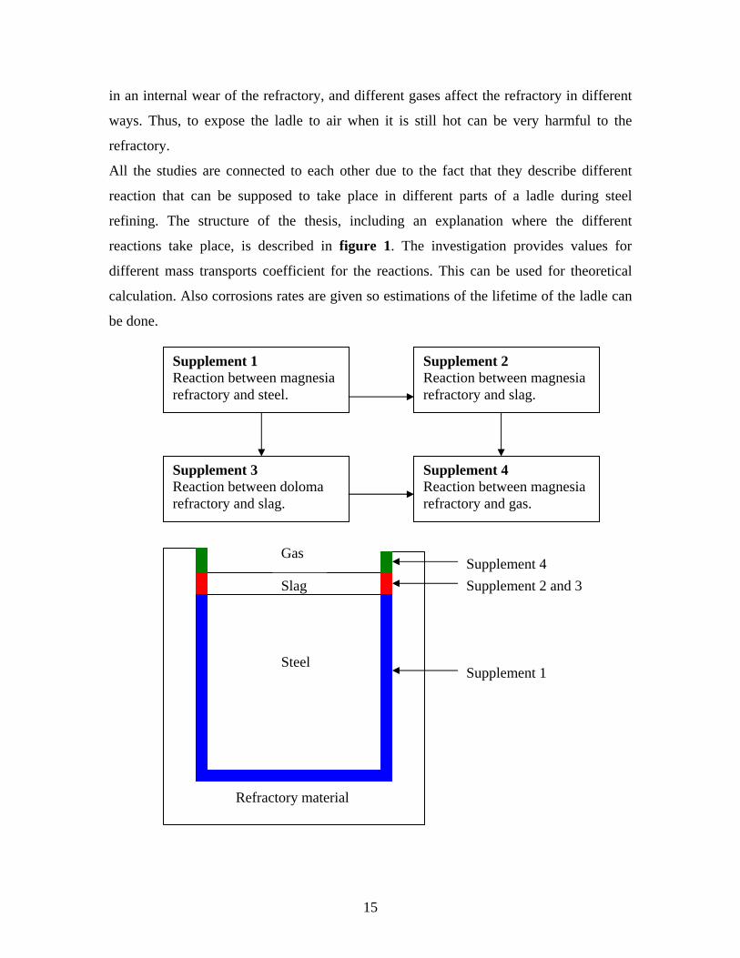
All the studies are connected to each other due to the fact that they describe different
reaction that can be supposed to take place in different parts of a ladle during steel
refining. The structure of the thesis, including an explanation where the different
reactions take place, is described in figure 1. The investigation provides values for
different mass transports coefficient for the reactions. This can be used for theoretical
calculation. Also corrosions rates are given so estimations of the lifetime of the ladle can
be done.
Supplement 2 Reaction between magnesia refractory and slag.
Supplement 1 Reaction between magnesia refractory and steel.
Supplement 4 Reaction between magnesia refractory and gas.
Supplement 3 Reaction between doloma refractory and slag.
Slag
Refractory material
Gas
Steel Supplement 1
Supplement 4 Supplement 2 and 3
15
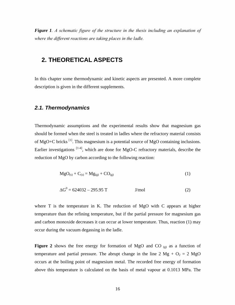
Figure 1. A schematic figure of the structure in the thesis including an explanation of
where the different reactions are taking places in the ladle.
2. THEORETICAL ASPECTS
In this chapter some thermodynamic and kinetic aspects are presented. A more complete
description is given in the different supplements.
2.1. Thermodynamics
Thermodynamic assumptions and the experimental results show that magnesium gas
should be formed when the steel is treated in ladles where the refractory material consists
of MgO+C bricks [1]. This magnesium is a potential source of MgO containing inclusions.
Earlier investigations [1-4], which are done for MgO-C refractory materials, describe the
reduction of MgO by carbon according to the following reaction:
MgO(s) + C(s) = Mg(g) + CO(g) (1)
ΔG0 = 624032 – 295.95 T J/mol (2)
where T is the temperature in K. The reduction of MgO with C appears at higher
temperature than the refining temperature, but if the partial pressure for magnesium gas
and carbon monoxide decreases it can occur at lower temperature. Thus, reaction (1) may
occur during the vacuum degassing in the ladle.
Figure 2 shows the free energy for formation of MgO and CO (g) as a function of
temperature and partial pressure. The abrupt change in the line 2 Mg + O2 = 2 MgO
occurs at the boiling point of magnesium metal. The recorded free energy of formation
above this temperature is calculated on the basis of metal vapour at 0.1013 MPa. The
16
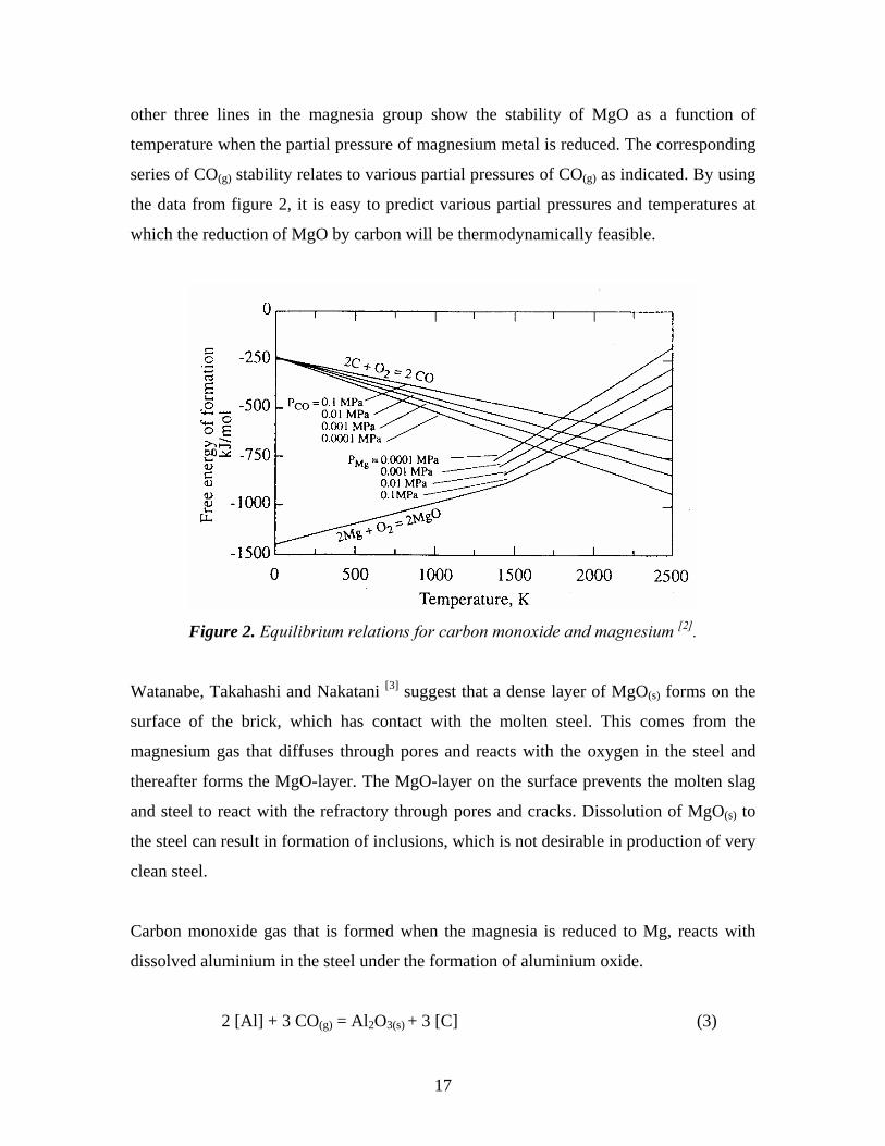
other three lines in the magnesia group show the stability of MgO as a function of
temperature when the partial pressure of magnesium metal is reduced. The corresponding
series of CO(g) stability relates to various partial pressures of CO(g) as indicated. By using
the data from figure 2, it is easy to predict various partial pressures and temperatures at
which the reduction of MgO by carbon will be thermodynamically feasible.
Figure 2. Equilibrium relations for carbon monoxide and magnesium [2].
Watanabe, Takahashi and Nakatani [3] suggest that a dense layer of MgO(s) forms on the
surface of the brick, which has contact with the molten steel. This comes from the
magnesium gas that diffuses through pores and reacts with the oxygen in the steel and
thereafter forms the MgO-layer. The MgO-layer on the surface prevents the molten slag
and steel to react with the refractory through pores and cracks. Dissolution of MgO(s) to
the steel can result in formation of inclusions, which is not desirable in production of very
clean steel.
Carbon monoxide gas that is formed when the magnesia is reduced to Mg, reacts with
dissolved aluminium in the steel under the formation of aluminium oxide.
2 [Al] + 3 CO(g) = Al2O3(s) + 3 [C] (3)
17
Together with MgO they can form a spinel inclusion according to the following
reactions:
[Mg] + CO(g) = MgO(s) + [C] (4)
Al2O3(s) + MgO(s) = MgO⋅Al2O3(s) (5)
The overall reaction involves the following steps: 1) Diffusion of CO(g) to the boundary
layer, 2) Chemical reaction of CO(g) at the interface, 3) Diffusion of dissolved C and O to
the bulk and the growth of the oxide at the interface.
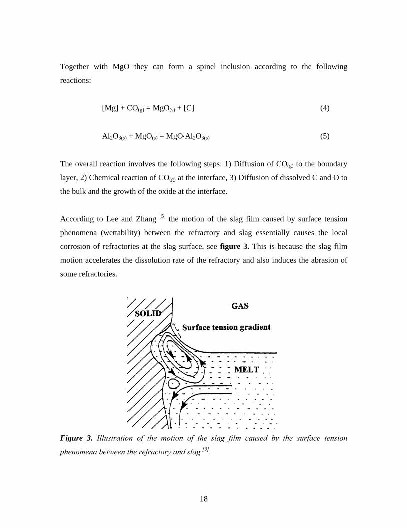
According to Lee and Zhang [5] the motion of the slag film caused by surface tension
phenomena (wettability) between the refractory and slag essentially causes the local
corrosion of refractories at the slag surface, see figure 3. This is because the slag film
motion accelerates the dissolution rate of the refractory and also induces the abrasion of
some refractories.
Figure 3. Illustration of the motion of the slag film caused by the surface tension
phenomena between the refractory and slag [5].
18
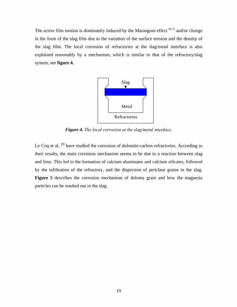
The active film motion is dominantly induced by the Marangoni effect [6-7] and/or change
in the form of the slag film due to the variation of the surface tension and the density of
the slag film. The local corrosion of refractories at the slag/metal interface is also
explained reasonably by a mechanism, which is similar to that of the refractory/slag
system, see figure 4.
Refractories
Metal
Slag
Figure 4. The local corrosion at the slag/metal interface.
Le Coq et al. [8] have studied the corrosion of dolomite-carbon refractories. According to
their results, the main corrosion mechanism seems to be due to a reaction between slag
and lime. This led to the formation of calcium aluminates and calcium silicates, followed
by the infiltration of the refractory, and the dispersion of periclase grains in the slag.
Figure 5 describes the corrosion mechanism of doloma grain and how the magnesia
particles can be washed out in the slag.
19
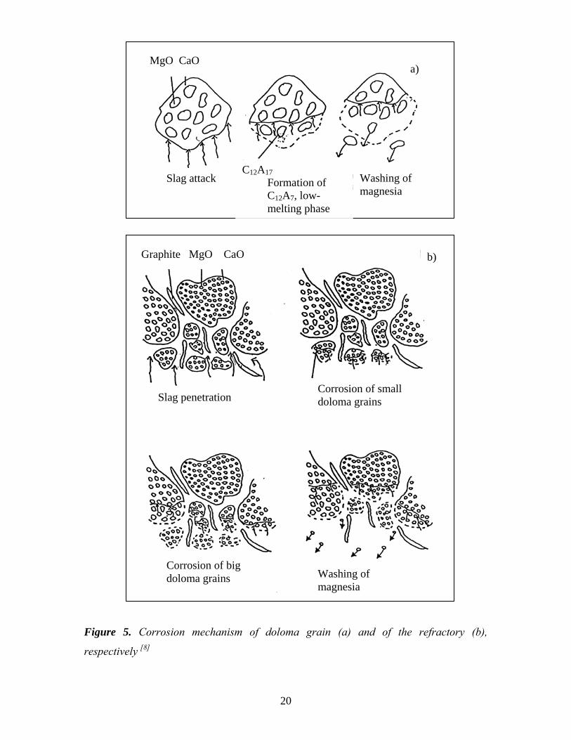
MgO CaO a)
Washing of magnesia
Slag attack C12A17 Formation of C12A7, low- melting phase
Graphite MgO CaO b)
Corrosion of small Slag penetration doloma grains
Corrosion of big Washing of doloma grains magnesia
Figure 5. Corrosion mechanism of doloma grain (a) and of the refractory (b),
respectively [8]
20
When carbon bonded magnesia (MgO-C) refractory materials are used in the lining of
ladles when refining of steel is carried out, they inhibit slag penetration into the brick
structure because of the low wettability of graphite by slag. In addition, they inhibit the
brick from thermo-mechanically spalling (surface splitting of the lining) due to graphite’s
high thermal conductivity and low thermal expansion. Although graphite has a high
chemical stability when it is in contact with a molten slag, it is easily oxidized by iron
oxide in the slag, ambient gas and MgO (MgO-C reaction). The gas-phase oxidation is
caused by oxygen and carbon dioxide in the ambient atmosphere reacting with the carbon
in the refractory. This type of oxidation is significant during the heating of ladles as well
as transportation of ladles. However, several studies have shown that the formation of a
slag layer on the brick surface will decrease the decarburization tendency. [2, 9-11]
Equation (1) can be obtained by combining the following two reactions:
Mg(g) + ½ O2(g) = MgO(s) (6)
C(s) + ½ O2(g) = CO(g) (7)
The free energy changes for equations (1), (6) and (7) in the temperature range 298-2000 K can be calculated as follows using standard reference tables [12]:
ΔG1 = - 615 600 + 1118,23 T – RT ln PMg – RT ln PCO (8)
ΔG2 = - 730 000 + 204T + RT ln 22
1
1
OMg pp ⋅ (9)
ΔG3 = - 114 400 – 85.77 T + RT ln 22
1
O
CO
p
p (10)
On the basis of the thermodynamic arguments, the rate of the internal oxide-carbon
reactions would be expected to increase with an increasing temperature. Furthermore, to
21
decrease at a given temperature with an increase in either PMg or PCO in the ambient
atmosphere [8]. The influence of the temperature and the partial pressure of Mg(g) and
CO(g) on reaction (1) is also illustrated in figure 2. Magnesium is characterized by a high
affinity to oxygen and a very stable oxide. At a temperature of 2120 K and a pressure of 1
atm, the MgO and CO lines cross each other, as illustrated in figure 2. This means that
magnesium oxide can be reduced by a reaction with carbon and form magnesium gas
according to reaction (1).
Sunayama and Kawahara [13] have studied decarburization of resin-bonded magnesia–
carbon refractory in the temperature range from 1473 – 1673 K in N2-O2 and Ar-O2
atmospheres. After kinetic analysis, it was suggested that the overall oxidation process
was controlled by the diffusion of oxygen through the decarburized layer. The
confirmation of a dense layer formation on the surface of the sample was obtained from
the observation of the cross section of the sample after the oxidation test.
Generally speaking, the corrosion process could be defined as any type of interaction
between a solid phase and a fluid phase that results in a deterious effect to either of the
phases. The corrosion process is connected with a so-called slag resistance. The
resistance of refractories toward slag is determined first of all by equilibrium relations. It
is clear that a slag, which is already saturated with a solid phase, can not further attack a
refractory consisting of that solid phase. During the ladle refining of steel the corrosion of
the refractory is a very complex process, which is dependent on many factors. Some of
the factors are depended on reaction kinetics, which will be discussed below.
2.2. Kinetics
Corrosion of the lining material in contact with slag during ladle refining of steel is
usually described to take place due to the following phenomena:
22
• Dissolution, or diffusion, which is a chemical process by which the refractory
material is continuously dissolved
• Penetration, by which the slag penetrates into the refractory and causes
mechanical effects
• Erosion, which is the abrasion process of the refractory material exposed to gas
and slag movement
Dissolution of the refractory in liquid slag is usually expressed in terms of a dissolution
rate, which is the rate at which the thickness of the refractory is depleted. It is known that
mass transfer is the dominant rate controlling step in the dissolution processes of solids
into liquids. Furthermore, that the dissolution rate could be expressed by the following
equation [14], which also has been used in the present study:
- Adtdr
= oUb, (11)
where r is the radius of the rotating cylinder, t is the time, Ao is a specific constant for
different conditions, U is the periphery velocity of the rotating cylinder and b is a
constant. The dissolution rate can then be expressed by equation (12):
v = k (ns-nb) (12)
where v is the rate of dissolution, k is the mass transfer coefficient and ns, nb is
concentration content in steel/slag at the interface and in the bulk, respectively.
A common way to simulate the dissolution of solid material into liquid is to rotate the
solid sample in the liquid with a fixed rotational speed. Taking into account the
dissolution of a magnesia rotating sample into steel or slag, the mass balance of the oxide
may be written as follows:
23
- ⟩−⟨= bbss MgMgkdtdr ρρ
ρ)()(%
100 (13)
- ⟩−⟨= bbss MgOMgOkdtdr ρρ
ρ)()(%
100 (14)
where ρ is the bulk density of the MgO-C rotating disk, and ρs and ρb denote the slag/steel
density at the interface and the bulk, respectively.
On the other hand, according to Umakoshi et al. [15] it is impossible to determine the mass
transfer coefficient for doloma by equation (14), since CaO and MgO may individually
dissolve from the surface of the doloma (a mixture of CaO and MgO particles). However,
if the dissolution of CaO in the doloma is much slower than that of MgO, i.e., mass
transfer of CaO in the slag boundary layer controls the rate of dissolution, it must be
expressed by equation (15) because of the equal mole fractions of CaO and MgO.
CD nMM
n && ⋅⎟⎟⎠
⎞⎜⎜⎝
⎛+=
CaO
MgO1 (15)
where and are the rate of dissolution of doloma and calcia, respectively and MDn& Cn& MgO
and MCaO are the molecular weights of MgO and CaO, respectively. On the contrary, if
mass transfer of MgO controls the rate of dissolution, it may be expressed as equation
(16).
MD nMM
n && ⋅⎟⎟⎠
⎞⎜⎜⎝
⎛+=
MgO
CaO1 (16)
where and are the rate of dissolution of doloma and magnesia, respectively. Dn& Mn&
The rates of dissolution of CaO and MgO have been determined before as being
cm/s
4107.7 −⋅5 and cm/s 41067.1 −⋅ 9, respectively. Taking into account the above values it is
24
concluded that the magnesia dissolution process is the rate-controlling step and equation
(16) is valid for characterizing the doloma dissolution process.
Taking into account the dissolution of a doloma rotating sample into slag, the mass
balance of the oxide may therefore be written as follows:
⟩−⟨⎟⎟⎠
⎞⎜⎜⎝
⎛+=− bbss MgOMgOk
MM
dtdr ρρ
ρ)()(%
1001
MgO
CaO (17)
According to Fruehan et al. [16] the mass transfer calculation in the dissolution process of
solid into gases can be described as follows:
tkw
ww t ⋅−=⎟⎟⎠
⎞⎜⎜⎝
⎛ −−
0
01ln (18)
where wo is the weight of the sample before the test, wt is the weight of the sample after
time t.
Generally speaking the dissolution of the refractory into the slag at the interface is
governed by the following mechanism, see also figure 6:
- Chemical reaction at the interface
- Transport of reacting species through the liquid slag
In figure 6 you can see that the slag has attacked the refractory and penetrated into the
refractory, and at the same time the dissolution of refractory material into the slag has
continued. After a while, t = t2, the penetration of the slag has reach deeper into the
refractory material and the boundary layer has diffused/eroded into the slag.
25
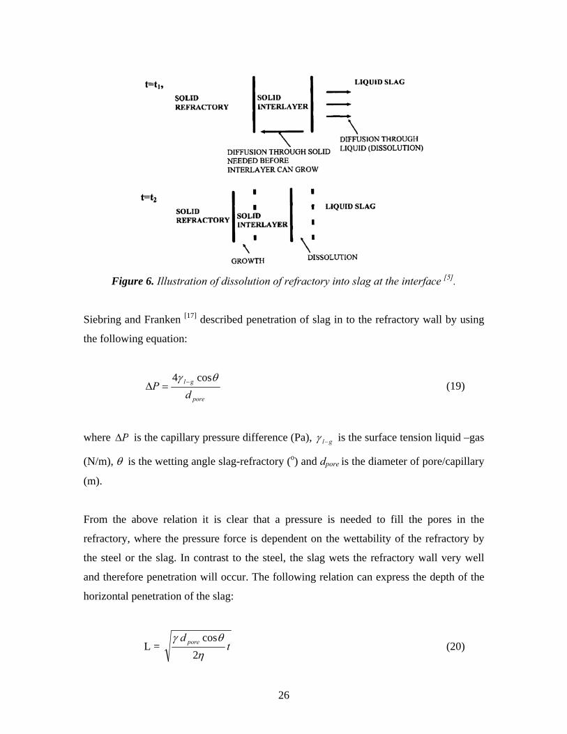
Figure 6. Illustration of dissolution of refractory into slag at the interface [5].
Siebring and Franken [17] described penetration of slag in to the refractory wall by using
the following equation:
pore
gl
dP
θγ cos4 −=Δ (19)
where PΔ is the capillary pressure difference (Pa), gl−γ is the surface tension liquid –gas
(N/m), θ is the wetting angle slag-refractory (o) and dpore is the diameter of pore/capillary
(m).
From the above relation it is clear that a pressure is needed to fill the pores in the
refractory, where the pressure force is dependent on the wettability of the refractory by
the steel or the slag. In contrast to the steel, the slag wets the refractory wall very well
and therefore penetration will occur. The following relation can express the depth of the
horizontal penetration of the slag:
L = td pore
ηθγ
2cos
(20)
26
where L is the penetration depth (m), γ is the surface tension of liquid slag (N/m), dpore is
the pore diameter (m), θ is the contact angle between refractory and slag (o), η is the
viscosity of slag (Pa.s) and t is the time (s).
The viscosity is an important factor that affects the penetration. At the boundary layer,
where the slag dissolves some refractory oxide, the viscosity of the slag will increase and
the further attack by the slag is then only possible by diffusion through a viscous slag
layer at the interface. At the same time, it is seen from the equation (19) that slag
resistance is also affected by the refractory porosity. A porous refractory is more easily
corroded by the slag, which soaks into the pores, whereas a dense single phase refractory
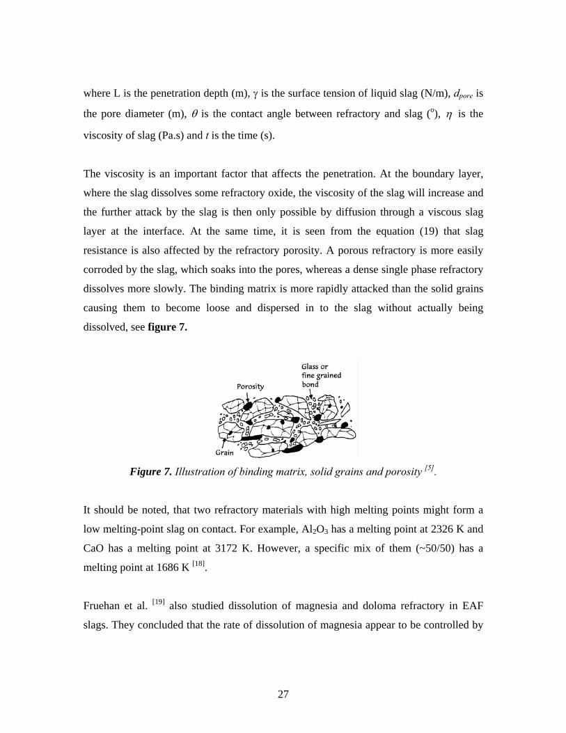
dissolves more slowly. The binding matrix is more rapidly attacked than the solid grains
causing them to become loose and dispersed in to the slag without actually being
dissolved, see figure 7.
Figure 7. Illustration of binding matrix, solid grains and porosity [5].
It should be noted, that two refractory materials with high melting points might form a
low melting-point slag on contact. For example, Al2O3 has a melting point at 2326 K and
CaO has a melting point at 3172 K. However, a specific mix of them (~50/50) has a
melting point at 1686 K [18].
Fruehan et al. [19] also studied dissolution of magnesia and doloma refractory in EAF
slags. They concluded that the rate of dissolution of magnesia appear to be controlled by
27
the liquid mass transfer. Furthermore, that the rate of dissolution of doloma refractory
seemed to be slightly faster than that of magnesia.
When the vertical penetration is analysed the following equation is recommended by Riaz
et al. [20].
L = gR ρθγ cos2 (21)
where R is the pore radius (m), ρ is the slag density (kg/m3) and g is the gravitational
constant (m/s2).
The above equations (20) + (21) show that penetration decreases with decreasing surface
tension, increasing viscosity and contact angle when θ > 90o.
Slag penetration into the pores can cause deterioration of the refractory wall by the
following mechanisms:
- Dissolving of the refractory material into the slag which changing the slag
properties
- Differential expansion or contraction between refractory and the slag causing
stresses and cracks in the lining
- Spalling, which can be taken to be the same as the depth of slag penetration,
Dp[21].
Erosion of the refractory material in contact with the slag is dependent on the abrasion,
which is determined by the high-velocity slag and gases. It is a common opinion that the
erosion effects are not so high when alumina or magnesia linings are used.
As a conclusion, the corrosion rate increases as the temperature increases. The corrosion
rate is typically higher for a polycrystalline ceramic than for a single crystal, due to grain
28

boundary effects. The corrosion rate is lower for a natural convection than for a forced
convection where either the melt is flowing or the ceramics is moving.
29
3. EXPERIMENTAL METHODS
In order to experimentally study the corrosion mechanism and kinetic behaviour of the
commercial refractory materials in contact with molten steel, molten slag and gas,
laboratory trials were conducted. The experimental procedure for each type of experiment
is briefly described below. A more comprehensive description is given in the
supplements: Refractory/steel (S1), refractory/slag (S2 and S3) and refractory/gas (S4).
3.1. Reactions between refractory and steel, (S1)
Details of the refractory/steel laboratory trials are given in supplement 1.
3.1.1. Materials
The chemical composition of the refractory material that was used in the experiments
with molten steel is shown in table 1. As can be seen, the main component is MgO and
the retained carbon content is 5.5 %.
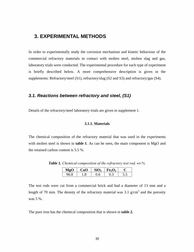
Table 1. Chemical composition of the refractory test rod, wt-%.
MgO CaO SiO2 Fe2O3 C 96.8 1.8 0.6 0.3 5.5
The test rods were cut from a commercial brick and had a diameter of 13 mm and a
length of 70 mm. The density of the refractory material was 3.1 g/cm3 and the porosity
was 5 %.
The pure iron has the chemical composition that is shown in table 2.
30
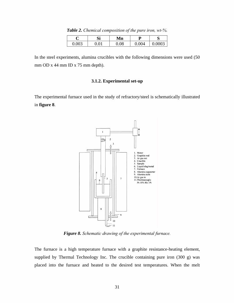
Table 2. Chemical composition of the pure iron, wt-%.
C Si Mn P S 0.003 0.01 0.08 0.004 0.0003
In the steel experiments, alumina crucibles with the following dimensions were used (50
mm OD x 44 mm ID x 75 mm depth).
3.1.2. Experimental set-up
The experimental furnace used in the study of refractory/steel is schematically illustrated
in figure 8.
Figure 8. Schematic drawing of the experimental furnace.
The furnace is a high temperature furnace with a graphite resistance-heating element,
supplied by Thermal Technology Inc. The crucible containing pure iron (300 g) was
placed into the furnace and heated to the desired test temperatures. When the melt
31
temperature reached the desirable level, the iron was killed with an addition of 0.1 or 0.01
wt-% metallic aluminium. Thereafter, the test rod was immersed into the melt and rotated
with different rotation speeds at different holding times. Note, that the rod was rotated in
order to simulate the effect of stirring in the ladle. More specifically, the stirring will lead
to velocities along the refractory, which in turn will affect the refractory wear. The
furnace was flushed with 2 l/min of argon gas during all the tests. Traces of moisture,
CO2 and oxygen in the commercial Ar gas (supplied by Air Liquid, 99.9997 % pure)
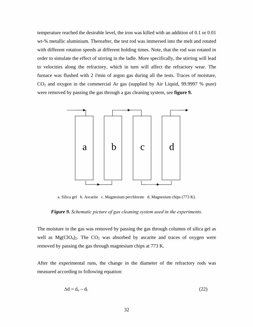
were removed by passing the gas through a gas cleaning system, see figure 9.
a b c d
a. Silica gel b. Ascarite c. Magnesium perchlorate d. Magnesium chips (773 K).
Figure 9. Schematic picture of gas cleaning system used in the experiments.
The moisture in the gas was removed by passing the gas through columns of silica gel as
well as Mg(ClO4)2. The CO2 was absorbed by ascarite and traces of oxygen were
removed by passing the gas through magnesium chips at 773 K.
After the experimental runs, the change in the diameter of the refractory rods was
measured according to following equation:
Δd = do – dt (22)
32
where do is the initial diameter of the rod and dt the diameter at time (t). The error was
estimated to be ± 0.02 mm. The chemical composition of the steel was determined using
an Optical Emission Spectrometer (OES). In addition, the test rods were analysed in a
Scanning Electron Microscope (SEM) in combination with an Energy Dispersive X-ray
Spectrometer (EDS). The inclusions found in the steel samples were also examined by
SEM/EDS. Thereafter, the samples were moulded in epoxy and the cross section
examined in microscope.
3.2. Reactions between refractory and slag, (S2 and S3)
Details of the refractory/slag experiments are discussed in supplements 2 and 3.
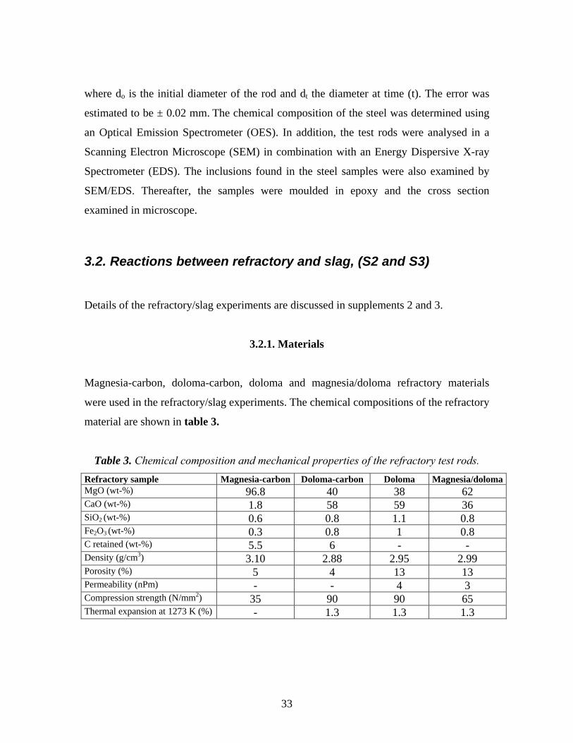
3.2.1. Materials
Magnesia-carbon, doloma-carbon, doloma and magnesia/doloma refractory materials
were used in the refractory/slag experiments. The chemical compositions of the refractory
material are shown in table 3.
Table 3. Chemical composition and mechanical properties of the refractory test rods. Refractory sample Magnesia-carbon Doloma-carbon Doloma Magnesia/dolomaMgO (wt-%) 96.8 40 38 62 CaO (wt-%) 1.8 58 59 36 SiO2 (wt-%) 0.6 0.8 1.1 0.8 Fe2O3 (wt-%) 0.3 0.8 1 0.8 C retained (wt-%) 5.5 6 - - Density (g/cm3) 3.10 2.88 2.95 2.99 Porosity (%) 5 4 13 13 Permeability (nPm) - - 4 3 Compression strength (N/mm2) 35 90 90 65 Thermal expansion at 1273 K (%) - 1.3 1.3 1.3
33
The doloma-carbon and magnesia-carbon test rods were cut from a commercial brick.
The test rods of doloma and magnesia/doloma were sintered samples. They had a
diameter of 13 mm and a length of 70 mm.
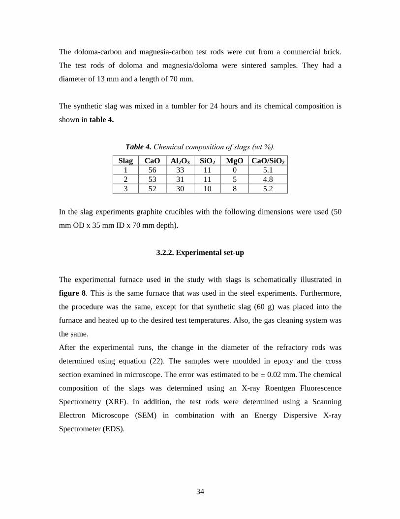
The synthetic slag was mixed in a tumbler for 24 hours and its chemical composition is
shown in table 4.
Table 4. Chemical composition of slags (wt %).
Slag CaO Al2O3 SiO2 MgO CaO/SiO21 56 33 11 0 5.1 2 53 31 11 5 4.8 3 52 30 10 8 5.2
In the slag experiments graphite crucibles with the following dimensions were used (50
mm OD x 35 mm ID x 70 mm depth).
3.2.2. Experimental set-up
The experimental furnace used in the study with slags is schematically illustrated in
figure 8. This is the same furnace that was used in the steel experiments. Furthermore,
the procedure was the same, except for that synthetic slag (60 g) was placed into the
furnace and heated up to the desired test temperatures. Also, the gas cleaning system was
the same.
After the experimental runs, the change in the diameter of the refractory rods was
determined using equation (22). The samples were moulded in epoxy and the cross
section examined in microscope. The error was estimated to be ± 0.02 mm. The chemical
composition of the slags was determined using an X-ray Roentgen Fluorescence
Spectrometry (XRF). In addition, the test rods were determined using a Scanning
Electron Microscope (SEM) in combination with an Energy Dispersive X-ray
Spectrometer (EDS).
34
3.3. Reactions between refractory and gas, (S4)
Details regarding the refractory/gas experiments are given in supplement 4.
3.3.1. Materials
The refractory test rods used in this experiment were from the same type of refractory
bricks that was used in the steel and slag tests. The chemical composition is shown in
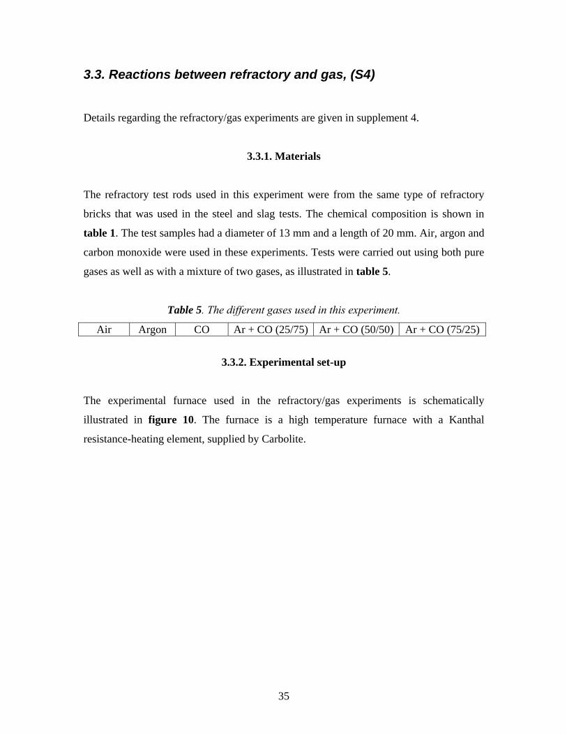
table 1. The test samples had a diameter of 13 mm and a length of 20 mm. Air, argon and
carbon monoxide were used in these experiments. Tests were carried out using both pure
gases as well as with a mixture of two gases, as illustrated in table 5.
Table 5. The different gases used in this experiment.
Air Argon CO Ar + CO (25/75) Ar + CO (50/50) Ar + CO (75/25)
3.3.2. Experimental set-up
The experimental furnace used in the refractory/gas experiments is schematically
illustrated in figure 10. The furnace is a high temperature furnace with a Kanthal
resistance-heating element, supplied by Carbolite.
35
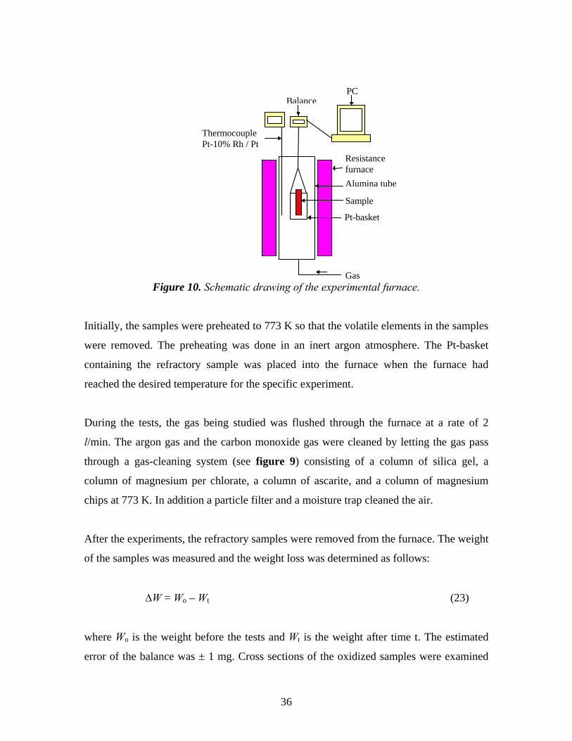
Figure 10. Schematic drawing of the experimental furnace. Gas
BalancePC
Resistancefurnace
Sample
Pt-basket
Alumina tube
Thermocouple Pt-10% Rh / Pt
Initially, the samples were preheated to 773 K so that the volatile elements in the samples
were removed. The preheating was done in an inert argon atmosphere. The Pt-basket
containing the refractory sample was placed into the furnace when the furnace had
reached the desired temperature for the specific experiment.
During the tests, the gas being studied was flushed through the furnace at a rate of 2
l/min. The argon gas and the carbon monoxide gas were cleaned by letting the gas pass
through a gas-cleaning system (see figure 9) consisting of a column of silica gel, a
column of magnesium per chlorate, a column of ascarite, and a column of magnesium
chips at 773 K. In addition a particle filter and a moisture trap cleaned the air.
After the experiments, the refractory samples were removed from the furnace. The weight
of the samples was measured and the weight loss was determined as follows:
ΔW = Wo – Wt (23)
where Wo is the weight before the tests and Wt is the weight after time t. The estimated
error of the balance was ± 1 mg. Cross sections of the oxidized samples were examined
36

by using a light optical microscope (LOM) and a Scanning Electron Microscope (SEM)
equipped with an Energy Dispersive X-ray Spectrometer (EDS).
37
4. EXPERIMENTAL RESULTS
The result chapter is divided into four parts. First, the most important results from the
refractory/steel experiments are presented (S1). Thereafter, in section 4.2 and 4.3 the
main results from the magnesia-carbon refractory/slag experiments (S2) and the doloma
refractory/slag experiments (S3) are given. Finally, the most important results from the
refractory/gas experiments are presented (S4).
4.1. Reaction between MgO-C refractory and molten steel, (S1)
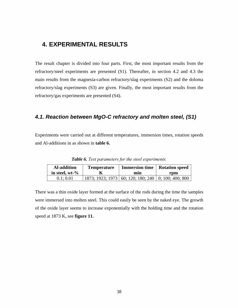
Experiments were carried out at different temperatures, immersion times, rotation speeds
and Al-additions in as shown in table 6.
Table 6. Test parameters for the steel experiments.
Al-addition in steel, wt-%
Temperature K
Immersion time min
Rotation speed rpm
0.1; 0.01 1873; 1923; 1973 60; 120; 180; 240 0; 100; 400; 800
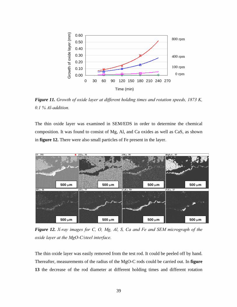
There was a thin oxide layer formed at the surface of the rods during the time the samples
were immersed into molten steel. This could easily be seen by the naked eye. The growth
of the oxide layer seems to increase exponentially with the holding time and the rotation
speed at 1873 K, see figure 11.
38
0.00
0.10
0.20
0.30
0.40
0.50
0.60
0 30 60 90 120 150 180 210 240 270
Time (min)
Gro
wth
of o
xide
laye
r (m
m)
800 rpm
400 rpm
0 rpm
100 rpm
Figure 11. Growth of oxide layer at different holding times and rotation speeds, 1873 K,
0.1 % Al-addition.
The thin oxide layer was examined in SEM/EDS in order to determine the chemical
composition. It was found to consist of Mg, Al, and Ca oxides as well as CaS, as shown
in figure 12. There were also small particles of Fe present in the layer.
500 μm
500 μm 500 μm
500 μm 500 μm
500 μm
500 μm
500 μm
Figure 12. X-ray images for C, O, Mg, Al, S, Ca and Fe and SEM micrograph of the
oxide layer at the MgO-C/steel interface.
The thin oxide layer was easily removed from the test rod. It could be peeled off by hand.
Thereafter, measurements of the radius of the MgO-C rods could be carried out. In figure
13 the decrease of the rod diameter at different holding times and different rotation
39
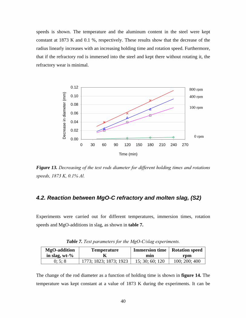
speeds is shown. The temperature and the aluminum content in the steel were kept
constant at 1873 K and 0.1 %, respectively. These results show that the decrease of the
radius linearly increases with an increasing holding time and rotation speed. Furthermore,
that if the refractory rod is immersed into the steel and kept there without rotating it, the
refractory wear is minimal.
0.00
0.02
0.04
0.06
0.08
0.10
0.12
0 30 60 90 120 150 180 210 240 270
Time (min)
Dec
reas
e in
dia
met
er (m
m)
400 rpm
800 rpm
100 rpm
0 rpm
Figure 13. Decreasing of the test rods diameter for different holding times and rotations
speeds, 1873 K, 0.1% Al.
4.2. Reaction between MgO-C refractory and molten slag, (S2)
Experiments were carried out for different temperatures, immersion times, rotation
speeds and MgO-additions in slag, as shown in table 7.
Table 7. Test parameters for the MgO-C/slag experiments.
MgO-addition in slag, wt-%
Temperature K
Immersion time min
Rotation speed rpm
0; 5; 8 1773; 1823; 1873; 1923 15; 30; 60; 120 100; 200; 400
The change of the rod diameter as a function of holding time is shown in figure 14. The
temperature was kept constant at a value of 1873 K during the experiments. It can be
40
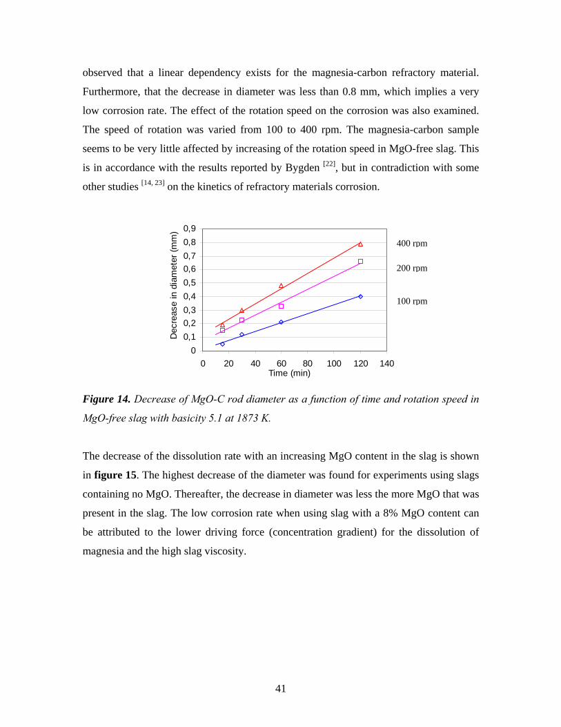
observed that a linear dependency exists for the magnesia-carbon refractory material.
Furthermore, that the decrease in diameter was less than 0.8 mm, which implies a very
low corrosion rate. The effect of the rotation speed on the corrosion was also examined.
The speed of rotation was varied from 100 to 400 rpm. The magnesia-carbon sample
seems to be very little affected by increasing of the rotation speed in MgO-free slag. This
is in accordance with the results reported by Bygden [22], but in contradiction with some
other studies [14, 23] on the kinetics of refractory materials corrosion.
00,10,20,30,40,50,60,70,80,9
0 20 40 60 80 100 120 140Time (min)
Dec
reas
e in
dia
met
er (m
m)
400 rpm
200 rpm
100 rpm
Figure 14. Decrease of MgO-C rod diameter as a function of time and rotation speed in
MgO-free slag with basicity 5.1 at 1873 K.
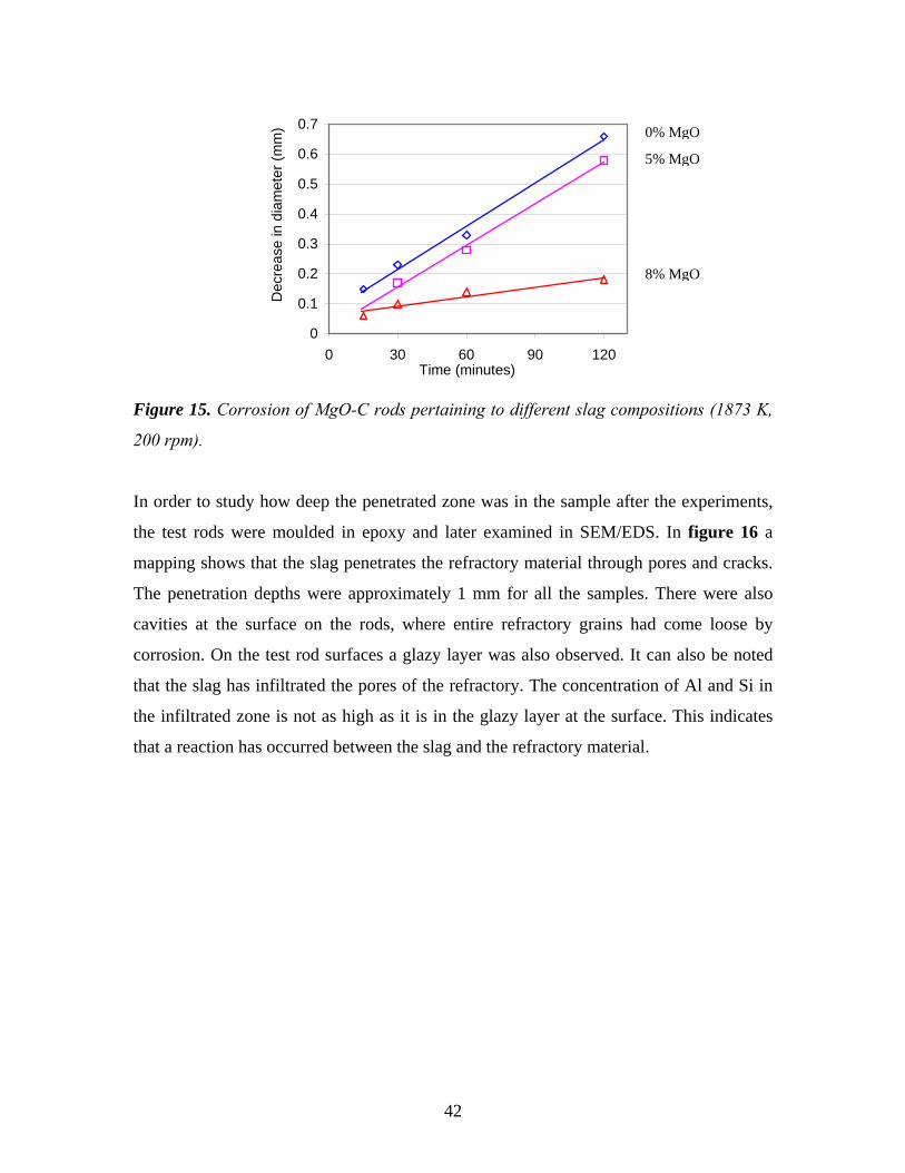
The decrease of the dissolution rate with an increasing MgO content in the slag is shown
in figure 15. The highest decrease of the diameter was found for experiments using slags
containing no MgO. Thereafter, the decrease in diameter was less the more MgO that was
present in the slag. The low corrosion rate when using slag with a 8% MgO content can
be attributed to the lower driving force (concentration gradient) for the dissolution of
magnesia and the high slag viscosity.
41
0
0.1
0.2
0.3
0.4
0.5
0.6
0.7
0 30 60 90 120Time (minutes)
Dec
reas
e in
dia
met
er (m
m)
0% MgO
5% MgO
8% MgO
Figure 15. Corrosion of MgO-C rods pertaining to different slag compositions (1873 K,
200 rpm).
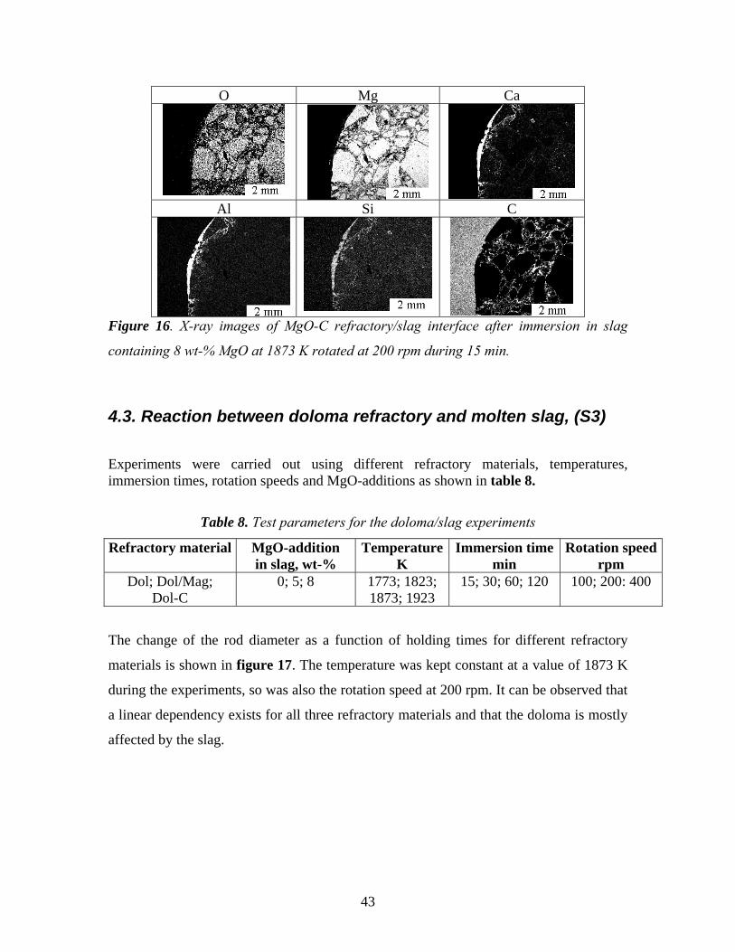
In order to study how deep the penetrated zone was in the sample after the experiments,
the test rods were moulded in epoxy and later examined in SEM/EDS. In figure 16 a
mapping shows that the slag penetrates the refractory material through pores and cracks.
The penetration depths were approximately 1 mm for all the samples. There were also
cavities at the surface on the rods, where entire refractory grains had come loose by
corrosion. On the test rod surfaces a glazy layer was also observed. It can also be noted
that the slag has infiltrated the pores of the refractory. The concentration of Al and Si in
the infiltrated zone is not as high as it is in the glazy layer at the surface. This indicates
that a reaction has occurred between the slag and the refractory material.
42
O Mg Ca
Al Si C
Figure 16. X-ray images of MgO-C refractory/slag interface after immersion in slag
containing 8 wt-% MgO at 1873 K rotated at 200 rpm during 15 min.
4.3. Reaction between doloma refractory and molten slag, (S3)
Experiments were carried out using different refractory materials, temperatures, immersion times, rotation speeds and MgO-additions as shown in table 8.
Table 8. Test parameters for the doloma/slag experiments
Refractory material MgO-addition in slag, wt-%
TemperatureK
Immersion time min
Rotation speedrpm
Dol; Dol/Mag; Dol-C
0; 5; 8 1773; 1823; 1873; 1923
15; 30; 60; 120 100; 200: 400
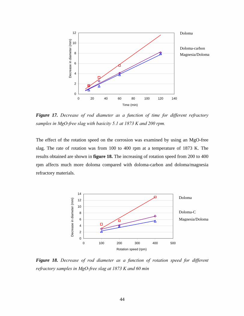
The change of the rod diameter as a function of holding times for different refractory
materials is shown in figure 17. The temperature was kept constant at a value of 1873 K
during the experiments, so was also the rotation speed at 200 rpm. It can be observed that
a linear dependency exists for all three refractory materials and that the doloma is mostly
affected by the slag.
43
0
2
4
6
8
10
12
0 20 40 60 80 100 120 140
Time (min)
Dec
reas
e in
dia
met
er (m
m)
Doloma
Doloma-carbonMagnesia/Doloma
Figure 17. Decrease of rod diameter as a function of time for different refractory
samples in MgO-free slag with basicity 5.1 at 1873 K and 200 rpm.
The effect of the rotation speed on the corrosion was examined by using an MgO-free
slag. The rate of rotation was from 100 to 400 rpm at a temperature of 1873 K. The
results obtained are shown in figure 18. The increasing of rotation speed from 200 to 400
rpm affects much more doloma compared with doloma-carbon and doloma/magnesia
refractory materials.
0
2
4
6
8
10
12
14
0 100 200 300 400 500
Rotation speed (rpm)
Dec
reas
e in
dia
met
er (m
m)
Doloma
Doloma-C
Magnesia/Doloma
Figure 18. Decrease of rod diameter as a function of rotation speed for different
refractory samples in MgO-free slag at 1873 K and 60 min
44
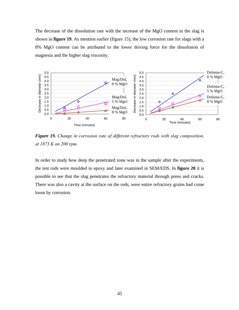
The decrease of the dissolution rate with the increase of the MgO content in the slag is
shown in figure 19. As mention earlier (figure 15), the low corrosion rate for slags with a
8% MgO content can be attributed to the lower driving force for the dissolution of
magnesia and the higher slag viscosity.
0.00.51.01.52.02.53.03.54.04.55.0
0 20 40 60 8Time (minutes)
Dec
reas
e in
dia
met
er (m
m) Doloma-C,
0 % MgO
Doloma-C, 5 % MgODoloma-C, 8 % MgO
0.00.51.01.52.02.53.03.54.04.55.0
0 20 40 60 8
Time (minutes)
Dec
reas
e in
dia
met
er (m
m)
Mag/Dol, 0 % MgO
Mag/Dol, 5 % MgOMag/Dol, 8 % MgO
0
0
Figure 19. Change in corrosion rate of different refractory rods with slag composition,
at 1873 K on 200 rpm.
In order to study how deep the penetrated zone was in the sample after the experiments,
the test rods were moulded in epoxy and later examined in SEM/EDS. In figure 20 it is
possible to see that the slag penetrates the refractory material through pores and cracks.
There was also a cavity at the surface on the rods, were entire refractory grains had come
loose by corrosion.
45
O Mg Ca
Al Si C
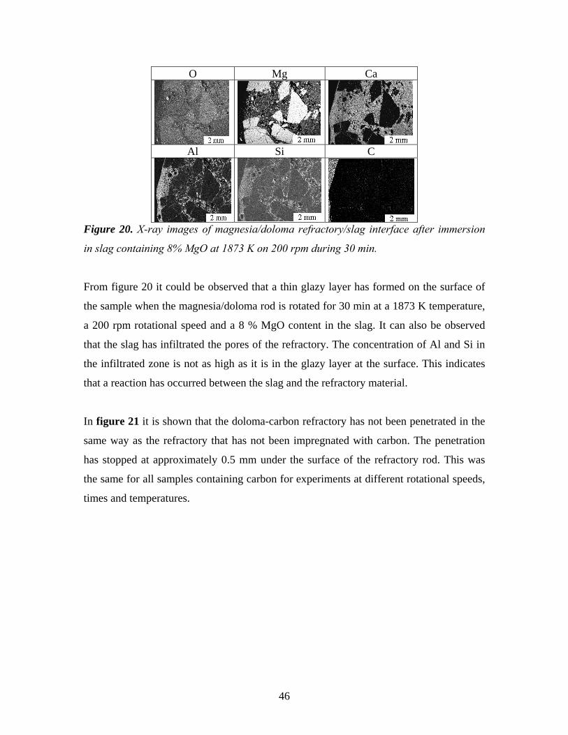
Figure 20. X-ray images of magnesia/doloma refractory/slag interface after immersion
in slag containing 8% MgO at 1873 K on 200 rpm during 30 min.
From figure 20 it could be observed that a thin glazy layer has formed on the surface of
the sample when the magnesia/doloma rod is rotated for 30 min at a 1873 K temperature,
a 200 rpm rotational speed and a 8 % MgO content in the slag. It can also be observed
that the slag has infiltrated the pores of the refractory. The concentration of Al and Si in
the infiltrated zone is not as high as it is in the glazy layer at the surface. This indicates
that a reaction has occurred between the slag and the refractory material.
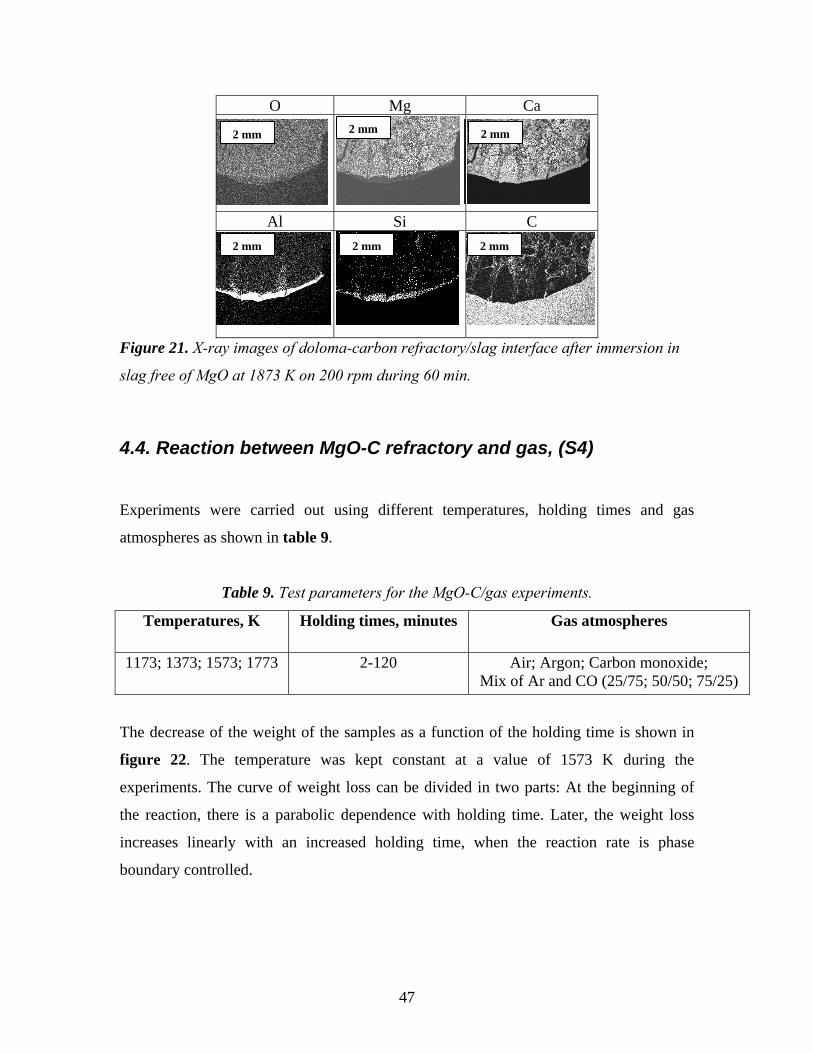
In figure 21 it is shown that the doloma-carbon refractory has not been penetrated in the
same way as the refractory that has not been impregnated with carbon. The penetration
has stopped at approximately 0.5 mm under the surface of the refractory rod. This was
the same for all samples containing carbon for experiments at different rotational speeds,
times and temperatures.
46
O Mg Ca
Al Si C
2 mm 2 mm2 mm
2 mm 2 mm 2 mm
Figure 21. X-ray images of doloma-carbon refractory/slag interface after immersion in
slag free of MgO at 1873 K on 200 rpm during 60 min.
4.4. Reaction between MgO-C refractory and gas, (S4)
Experiments were carried out using different temperatures, holding times and gas
atmospheres as shown in table 9.
Table 9. Test parameters for the MgO-C/gas experiments.
Temperatures, K Holding times, minutes Gas atmospheres
1173; 1373; 1573; 1773 2-120 Air; Argon; Carbon monoxide; Mix of Ar and CO (25/75; 50/50; 75/25)
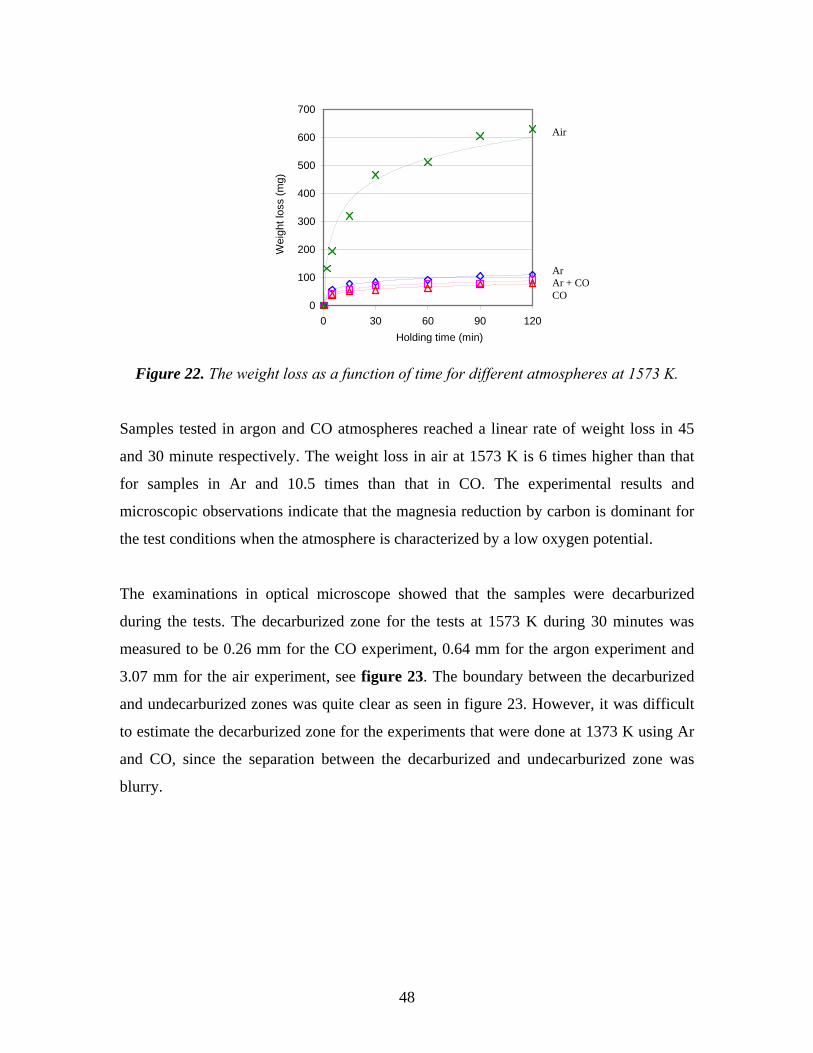
The decrease of the weight of the samples as a function of the holding time is shown in
figure 22. The temperature was kept constant at a value of 1573 K during the
experiments. The curve of weight loss can be divided in two parts: At the beginning of
the reaction, there is a parabolic dependence with holding time. Later, the weight loss
increases linearly with an increased holding time, when the reaction rate is phase
boundary controlled.
47
0
100
200
300
400
500
600
700
0 30 60 90 120Holding time (min)
Wei
ght l
oss
(mg)
Air
Ar Ar + CO CO
Figure 22. The weight loss as a function of time for different atmospheres at 1573 K.
Samples tested in argon and CO atmospheres reached a linear rate of weight loss in 45
and 30 minute respectively. The weight loss in air at 1573 K is 6 times higher than that
for samples in Ar and 10.5 times than that in CO. The experimental results and
microscopic observations indicate that the magnesia reduction by carbon is dominant for
the test conditions when the atmosphere is characterized by a low oxygen potential.
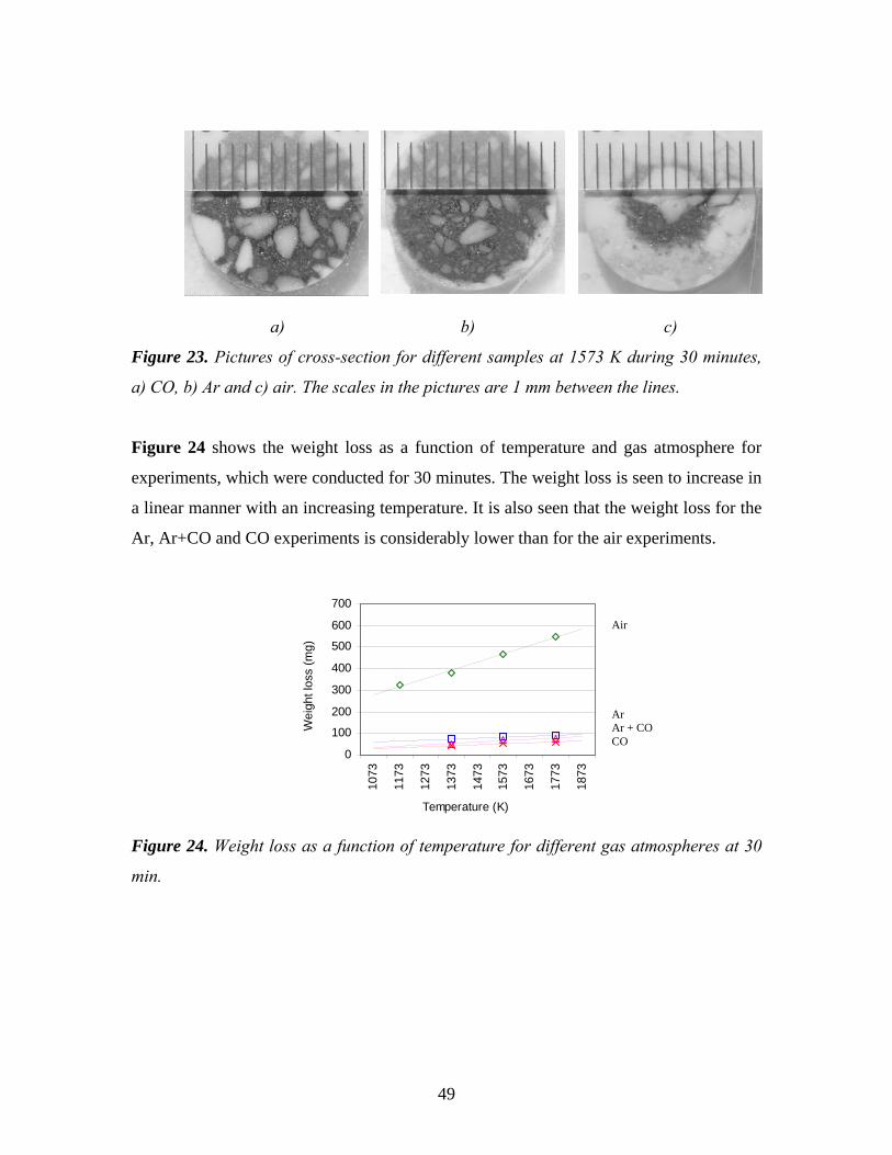
The examinations in optical microscope showed that the samples were decarburized
during the tests. The decarburized zone for the tests at 1573 K during 30 minutes was
measured to be 0.26 mm for the CO experiment, 0.64 mm for the argon experiment and
3.07 mm for the air experiment, see figure 23. The boundary between the decarburized
and undecarburized zones was quite clear as seen in figure 23. However, it was difficult
to estimate the decarburized zone for the experiments that were done at 1373 K using Ar
and CO, since the separation between the decarburized and undecarburized zone was
blurry.
48
a) b) c)
Figure 23. Pictures of cross-section for different samples at 1573 K during 30 minutes,
a) CO, b) Ar and c) air. The scales in the pictures are 1 mm between the lines.
Figure 24 shows the weight loss as a function of temperature and gas atmosphere for
experiments, which were conducted for 30 minutes. The weight loss is seen to increase in
a linear manner with an increasing temperature. It is also seen that the weight loss for the
Ar, Ar+CO and CO experiments is considerably lower than for the air experiments.
0
100
200
300
400
500
600
700
1073
1173
1273
1373
1473
1573
1673
1773
1873
Temperature (K)
Wei
ght l
oss
(mg)
Air
Ar Ar + CO CO
Figure 24. Weight loss as a function of temperature for different gas atmospheres at 30
min.
49
5. DISCUSSION
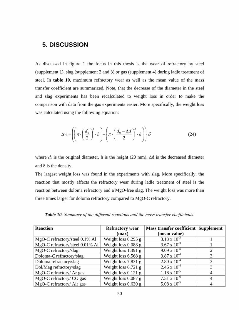
As discussed in figure 1 the focus in this thesis is the wear of refractory by steel
(supplement 1), slag (supplement 2 and 3) or gas (supplement 4) during ladle treatment of
steel. In table 10, maximum refractory wear as well as the mean value of the mass
transfer coefficient are summarized. Note, that the decrease of the diameter in the steel
and slag experiments has been recalculated to weight loss in order to make the
comparison with data from the gas experiments easier. More specifically, the weight loss
was calculated using the following equation:
δππ ⋅⎟⎟
⎠
⎞
⎜⎜
⎝
⎛
⎟⎟⎠
⎞⎜⎜⎝
⎛⋅⎟
⎠⎞
⎜⎝⎛ Δ−
⋅−⎟⎟⎠
⎞⎜⎜⎝
⎛⋅⎟
⎠⎞
⎜⎝⎛⋅=Δ h
ddh
dw
20
20
22 (24)
where d0 is the original diameter, h is the height (20 mm), Δd is the decreased diameter
and δ is the density.
The largest weight loss was found in the experiments with slag. More specifically, the
reaction that mostly affects the refractory wear during ladle treatment of steel is the
reaction between doloma refractory and a MgO-free slag. The weight loss was more than
three times larger for doloma refractory compared to MgO-C refractory.
Table 10. Summary of the different reactions and the mass transfer coefficients.
Reaction Refractory wear (max)
Mass transfer coefficient(mean value)
Supplement
MgO-C refractory/steel 0.1% Al Weight loss 0.295 g 3.13 x 10⁻³ 1 MgO-C refractory/steel 0.01% Al Weight loss 0.088 g 3.67 x 10⁻³ 1 MgO-C refractory/slag Weight loss 1.391 g 9.09 x 10⁻⁵ 2 Doloma-C refractory/slag Weight loss 6.568 g 3.87 x 10⁻⁴ 3 Doloma refractory/slag Weight loss 7.831 g 2.80 x 10⁻⁴ 3 Dol/Mag refractory/slag Weight loss 6.721 g 2.46 x 10⁻⁴ 3 MgO-C refractory/ Ar gas Weight loss 0.121 g 1.18 x 10⁻⁵ 4 MgO-C refractory/ CO gas Weight loss 0.087 g 7.51 x 10⁻⁶ 4 MgO-C refractory/ Air gas Weight loss 0.630 g 5.08 x 10⁻⁵ 4
50
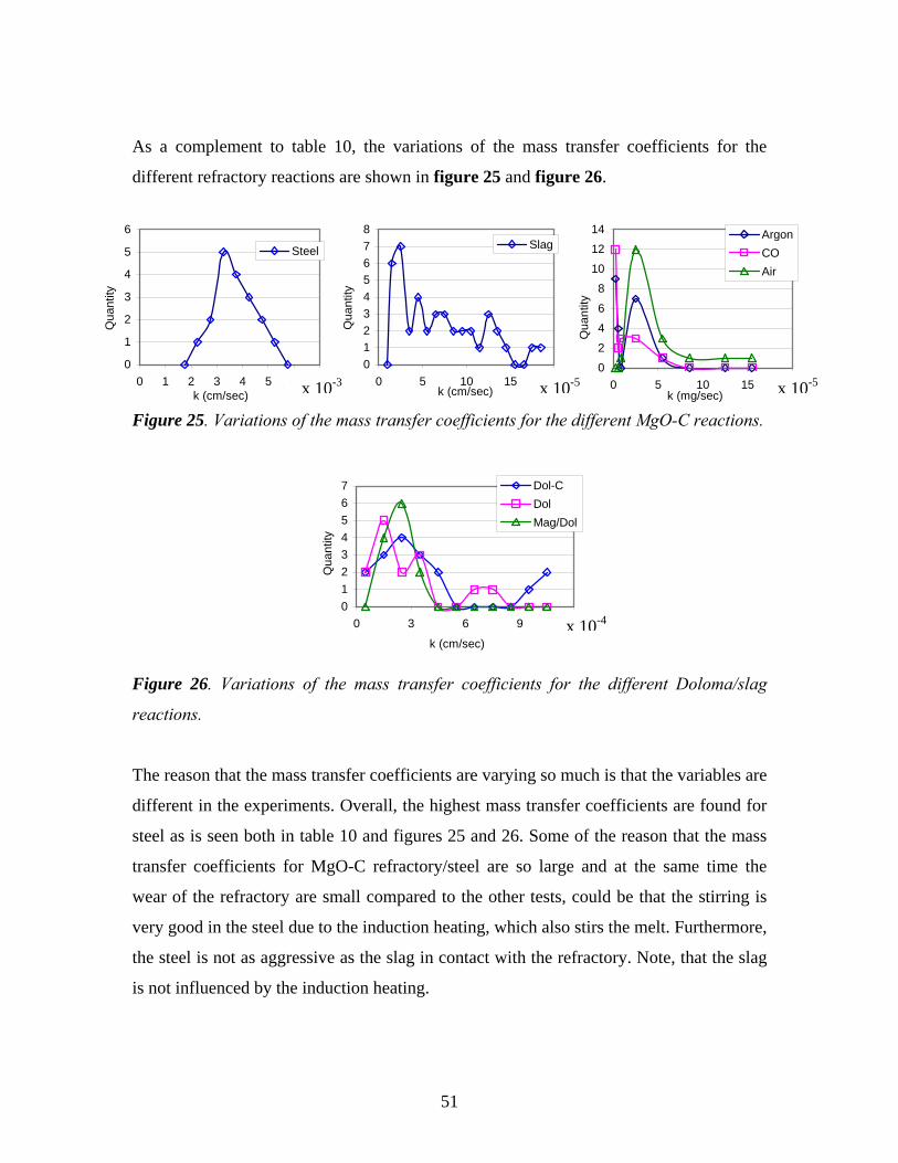
As a complement to table 10, the variations of the mass transfer coefficients for the
different refractory reactions are shown in figure 25 and figure 26.
0
1
2
3
4
5
6
0
2
4
6
8
10
12
14
0 5 10 15 20k (mg/sec)
Qua
ntity
ArgonCOAir
0 1 2 3 4 5 6 7012345678
0 5 10 15
SlagSteel
k (cm/sec)
Qua
ntity
k (cm/sec)
Qua
ntity
x 10-3
Figure 25. Variations of the mass transfer coefficients for the different MgO-C reactions.
01234567
0 3 6 9
k (cm/sec)
Qua
ntity
12
Dol-CDolMag/Dol
Figure 26. Variations of the mass transfer coefficients for the different Doloma/slag
reactions.
The reason that the mass transfer coefficients are varying so much is that the variables are
different in the experiments. Overall, the highest mass transfer coefficients are found for
steel as is seen both in table 10 and figures 25 and 26. Some of the reason that the mass
transfer coefficients for MgO-C refractory/steel are so large and at the same time the
wear of the refractory are small compared to the other tests, could be that the stirring is
very good in the steel due to the induction heating, which also stirs the melt. Furthermore,
the steel is not as aggressive as the slag in contact with the refractory. Note, that the slag
is not influenced by the induction heating.
20x 10-5 x 10-5
x 10-4
51
Below, first the effect of temperature, revolution speed and slag composition on the
dissolution rate is discussed. Then the formations of inclusions as well as oxide layers are
presented. The penetration of slag into the refractory is also treated more in detail.
Finally, the influence of the gas atmosphere on the weight loss and the oxide layers on
the reaction rate at the gas/refractory interface are discussed.
5.1. The effect of temperature on the dissolution rate
The wear mechanism of refractory materials by steel, slag and gas is a complex
phenomenon. The experimental results indicate that apart from the chemical attack of the
steel, slag and gas on the refractory material, penetration of the slag and gas cause serious
direct loss of the refractories.
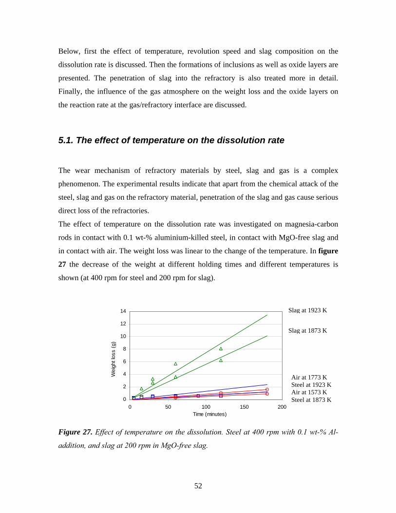
The effect of temperature on the dissolution rate was investigated on magnesia-carbon
rods in contact with 0.1 wt-% aluminium-killed steel, in contact with MgO-free slag and
in contact with air. The weight loss was linear to the change of the temperature. In figure
27 the decrease of the weight at different holding times and different temperatures is
shown (at 400 rpm for steel and 200 rpm for slag).
0
2
4
6
8
10
12
14
0 50 100 150 200Time (minutes)
Wei
ght l
oss
(g)
Slag at 1923 K
Slag at 1873 K
Air at 1773 K Steel at 1923 K Air at 1573 K Steel at 1873 K
Figure 27. Effect of temperature on the dissolution. Steel at 400 rpm with 0.1 wt-% Al-
addition, and slag at 200 rpm in MgO-free slag.
52
It is clear that the dissolution increases when the temperature increases. The increased
temperature affects the dissolution into slag more than it does into steel and gas.
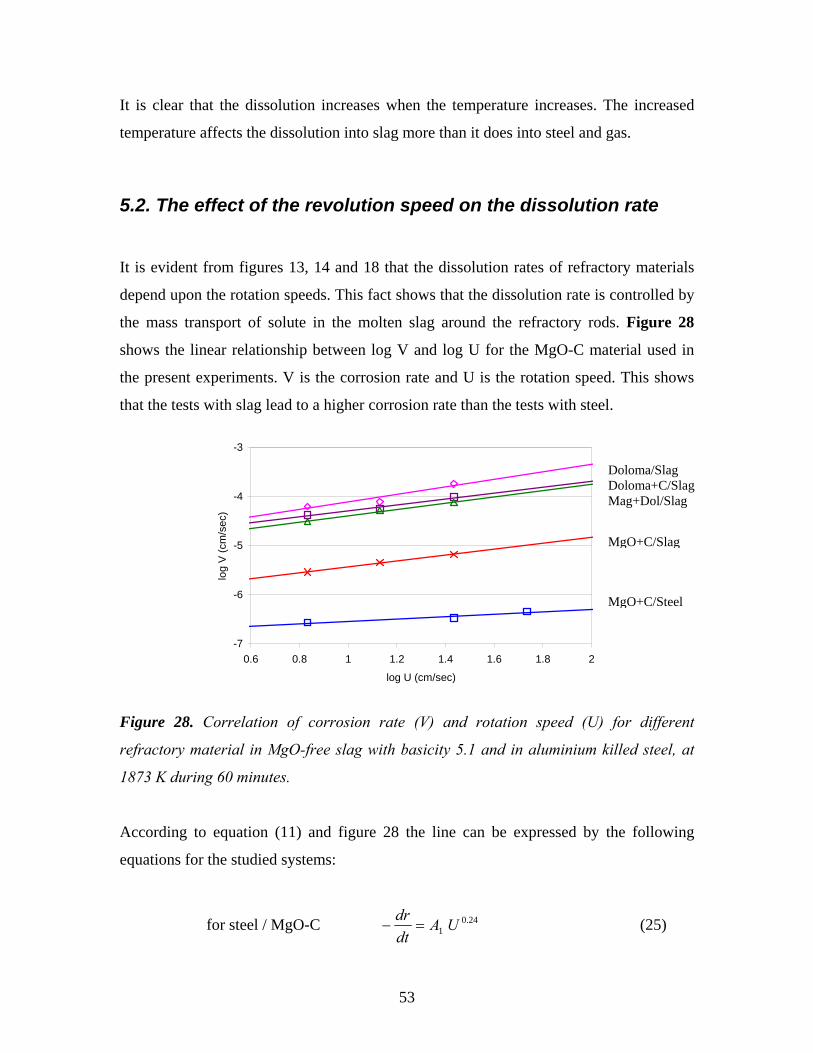
5.2. The effect of the revolution speed on the dissolution rate
It is evident from figures 13, 14 and 18 that the dissolution rates of refractory materials
depend upon the rotation speeds. This fact shows that the dissolution rate is controlled by
the mass transport of solute in the molten slag around the refractory rods. Figure 28
shows the linear relationship between log V and log U for the MgO-C material used in
the present experiments. V is the corrosion rate and U is the rotation speed. This shows
that the tests with slag lead to a higher corrosion rate than the tests with steel.
-7
-6
-5
-4
-3
0.6 0.8 1 1.2 1.4 1.6 1.8 2
log U (cm/sec)
log
V (c
m/s
ec)
Doloma/Slag Doloma+C/Slag Mag+Dol/Slag
MgO+C/Slag
MgO+C/Steel
Figure 28. Correlation of corrosion rate (V) and rotation speed (U) for different
refractory material in MgO-free slag with basicity 5.1 and in aluminium killed steel, at
1873 K during 60 minutes.
According to equation (11) and figure 28 the line can be expressed by the following
equations for the studied systems:
for steel / MgO-C 24.01 UA
dtdr
=− (25)
53
for slag / MgO-C 59.02 UA
dtdr
=− (26)
for slag / doloma 76.03 UA
dtdr
=− (27)
for slag / mag-dol 64.04 UA
dtdr
=− (28)
for slag / doloma-C 59.05 UA
dtdr
=− (29)
where A1, A2, A3, A4 and A5 are a constants. The constants 0.24, 0.59, 0.76, 0.64 and 0.59
were calculated from the slope of the lines in figure 28.
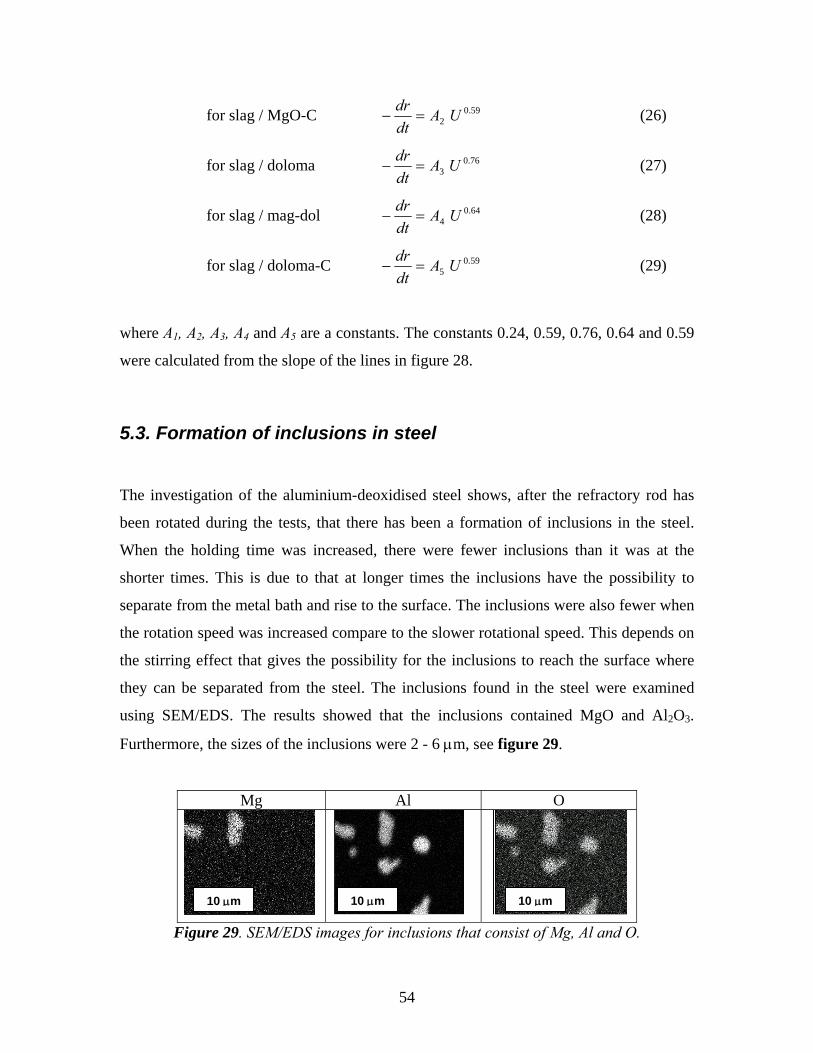
5.3. Formation of inclusions in steel
The investigation of the aluminium-deoxidised steel shows, after the refractory rod has
been rotated during the tests, that there has been a formation of inclusions in the steel.
When the holding time was increased, there were fewer inclusions than it was at the
shorter times. This is due to that at longer times the inclusions have the possibility to
separate from the metal bath and rise to the surface. The inclusions were also fewer when
the rotation speed was increased compare to the slower rotational speed. This depends on
the stirring effect that gives the possibility for the inclusions to reach the surface where
they can be separated from the steel. The inclusions found in the steel were examined
using SEM/EDS. The results showed that the inclusions contained MgO and Al2O3.
Furthermore, the sizes of the inclusions were 2 - 6 μm, see figure 29.
Mg Al O
Figure 29. SEM/EDS images for inclusions that consist of Mg, Al and O.
10 μm 10 μm 10 μm
54
The formation of spinel is practically a very significant aspect of the reaction between
MgO-C refractory and aluminium deoxidised molten steel. As the magnesium gas
diffuses into the molten steel the following reaction is taking place:
MgO⋅Al2O3 = [Mg] + 2[Al] + 4[O] (30)
For which the equilibrium constant can be written as:
Kspinel = ( aMg ⋅ a2Al⋅ a4
O / aMgO⋅Al2O3 ) (31)
As the initial alloys did not contain any magnesium, the presence of MgO in the
inclusions should indicate a result from the contamination by the refractories/steel
reaction. This was supported by the findings that no MgO was found in inclusions
analysed in steel samples taken before melting.
5.4. Formation of an oxide layer at the steel/refractory interface
According to Pickering and Batchelor [1] and Watanabe at al. [3] the reaction MgO(s) + C(s)
= Mg(g) + CO(g) proceeds to the right at higher temperatures and Mg(g) diffuses towards
the free surface of the sample where it encounters a higher PO2. Thereafter, magnesium is
oxidised to MgO, were it condenses and forms a MgO layer. At the same time, according
to Schwerdtfeger [24], Brabie [25] and Poirier at al. [26] the CO(g) formed during MgO(s)
reduction by carbon will diffuse to the interface where it will react with the molten steel
forming Al2O3 or MgO according to the following reactions:
2[Al] + 3CO(g) = Al2O3(s) + 3[C] (32)
[Mg] + CO(g) = MgO(s) + [C] (33)
55
These reactions occur in two stages. The first stage occurs immediately after the reactive
CO gas comes into contact with the surface of the steel. As a result, a thin oxide film of
Al2O3 and/or MgO is formed at the end of the first stage.
As an oxide layer is formed at the interface, the rate-controlling step for the second stage
of oxidation has been shown to be the growth of the oxide layer by dissociactive
adsorption of CO molecules at the gas/oxide interface. Now the diffusion through the
oxide layer will be the rate-controlling step. The formation of a surface layer will inhibit
any further oxidation by CO, by retarding the diffusion of carbon and oxygen across the
layer.
5.5. Penetration of slag into the refractory material
The dissolution process in the refractory material is verified by SEM investigations of the
samples. The slag has penetrated the refractory material in pores and cracks. It is possible
to observe that the slag phase has a concentration gradient at the boundary layer between
slag/refractory, see figure 30.
According to Cooper [27] the corrosion of oxides often occurs not by dissolution or
evaporation of the oxide, but by the penetration of the solid by some or all the elements
from the fluid slag. The liquid phase may be pulled into the open porosity of the solid by
capillary forces, and species from the fluid will diffuse both down the grain boundaries
and into the bulk of the solid.
This process can cause deterioration of the refractory materials by:
• Completely encasing solid particles by the molten slag
• Causing either an expansion or contraction of solid
• Diffusion of a slag species into the refractory material causing a change in the
physical properties
56
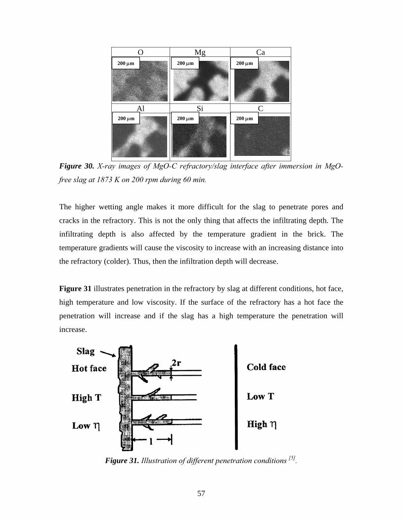
O Mg Ca
Al Si C
200
Figure 30. X-ray images of MgO-C refractory/slag interface after immersion in MgO-
free slag at 1873 K on 200 rpm during 60 min.
The higher wetting angle makes it more difficult for the slag to penetrate pores and
cracks in the refractory. This is not the only thing that affects the infiltrating depth. The
infiltrating depth is also affected by the temperature gradient in the brick. The
temperature gradients will cause the viscosity to increase with an increasing distance into
the refractory (colder). Thus, then the infiltration depth will decrease.
Figure 31 illustrates penetration in the refractory by slag at different conditions, hot face,
high temperature and low viscosity. If the surface of the refractory has a hot face the
penetration will increase and if the slag has a high temperature the penetration will
increase.
Figure 31. Illustration of different penetration conditions [5].
200 μm μm 200 μm
200 μm 200 μm 200 μm
57
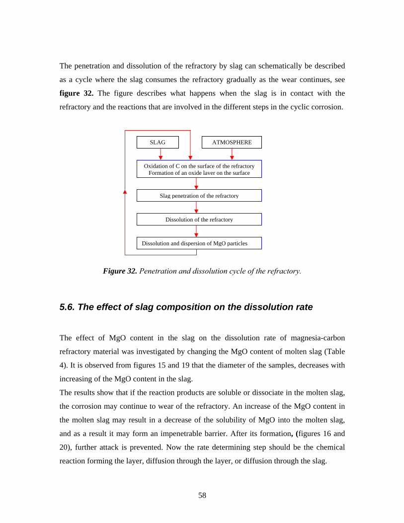
The penetration and dissolution of the refractory by slag can schematically be described
as a cycle where the slag consumes the refractory gradually as the wear continues, see
figure 32. The figure describes what happens when the slag is in contact with the
refractory and the reactions that are involved in the different steps in the cyclic corrosion.
SLAG ATMOSPHERE
Oxidation of C on the surface of the refractory Formation of an oxide layer on the surface
Slag penetration of the refractory
Dissolution of the refractory
Dissolution and dispersion of MgO particles
Figure 32. Penetration and dissolution cycle of the refractory.
5.6. The effect of slag composition on the dissolution rate
The effect of MgO content in the slag on the dissolution rate of magnesia-carbon
refractory material was investigated by changing the MgO content of molten slag (Table
4). It is observed from figures 15 and 19 that the diameter of the samples, decreases with
increasing of the MgO content in the slag.
The results show that if the reaction products are soluble or dissociate in the molten slag,
the corrosion may continue to wear of the refractory. An increase of the MgO content in
the molten slag may result in a decrease of the solubility of MgO into the molten slag,
and as a result it may form an impenetrable barrier. After its formation, (figures 16 and
20), further attack is prevented. Now the rate determining step should be the chemical
reaction forming the layer, diffusion through the layer, or diffusion through the slag.
58
5.7. The influence of the gas atmosphere on the weight loss
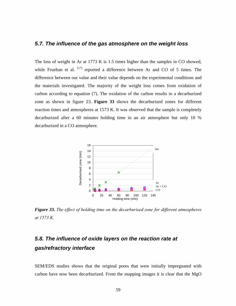
The loss of weight in Ar at 1773 K is 1.5 times higher than the samples in CO showed,
while Fruehan et al. [17] reported a difference between Ar and CO of 5 times. The
difference between our value and their value depends on the experimental conditions and
the materials investigated. The majority of the weight loss comes from oxidation of
carbon according to equation (7). The oxidation of the carbon results in a decarburized
zone as shown in figure 23. Figure 33 shows the decarburized zones for different
reaction times and atmospheres at 1573 K. It was observed that the sample is completely
decarburized after a 60 minutes holding time in an air atmosphere but only 10 %
decarburized in a CO atmosphere.
0
2
4
6
8
10
12
14
16
0 20 40 60 80 100 120 140Holding time (min)
Dec
arbu
rised
zon
e (m
m)
Air
Ar Ar + CO CO
Figure 33. The effect of holding time on the decarburised zone for different atmospheres
at 1573 K.
5.8. The influence of oxide layers on the reaction rate at
gas/refractory interface
SEM/EDS studies shows that the original pores that were initially impregnated with
carbon have now been decarburized. From the mapping images it is clear that the MgO
59
layer on the surface of the sample has less porosity than the original MgO grains. It is not
clear whether the MgO layer has recently been formed as a secondary layer or if it is
magnesium gas that has been reoxidised in pores and cracks and in that way formed a less
porous layer. The MgO layer has also been formed between the original MgO grains and
thereby filled up cavities present between the grains. A CaO layer was also found on the
outside of the MgO layer. This layer has probably been formed from calcium gas
originating from impurities inside the refractory material and which has been oxidised at
the surface. Both the MgO and CaO layers make the reaction rate inside the refractory
material decrease, since the reaction’s products must diffuse through the layers in order
for a further reaction to proceed. The formation of these layers is most likely dependent
on the temperature, because they were not observed at the lower experimental
temperatures.
60
6. CONCLUSIONS
The doctoral thesis has been focused on describing the wear of the refractory and the
affect it can have on the purity of steel during ladle treatment in a steel plant. This work
is presented in the four supplements that form the base for the thesis. In the first
supplement the growth of an MgO layer on the refractory surface is studied, as well as
the formation of inclusions in the steel. The main findings in Supplement 1 are:
• Penetration of molten steel was observed into the MgO-C refractory material and
it increases with the temperature, immersion time and rotation speed.
• The formation of the thin oxide layer at the interface is due to the reaction
between magnesium vapour and the CO(g) generated by the reaction between
MgO and C in the refractory rods.
• The activation energy of the corrosion reaction was calculated and the results
support the assumption that the mass transport is the rate-determining step.
• The oxide inclusions in the steel have been shown mainly to consist of MgO,
Al2O3 or mixture of these. The composition range, origin and mechanism of
formation of the oxide inclusions have been discussed and it is concluded that
MgO and spinel could be formed. Some of the finest inclusions are considered to
be formed as secondary inclusions during cooling and solidification of the steel
and they are connected only with the diffusion of magnesium from the refractory
rods to the molten steel
In supplement two the slag corrosion, erosion and penetration of magnesia refractory was
studied. The specific findings in Supplement 2 are:
61
• The results from calculation of the activation energy of the dissolution process
support the assumption that the mass-transfer step through the slag boundary layer
is the rate-determining step.
• The rod corrosion rates pertaining to experiments using MgO-free slag were
greater than those pertaining to experiments using a slag nearly saturated with
MgO.
• The corrosion mechanism appeared to be the dissolution of refractory material
into slag followed by the penetration of grain boundaries, and dispersion of the
grains into the slag.
Similar to the second supplement the slag corrosion, erosion and penetration of doloma
refractory was studied. The specific findings in Supplement 3 are:
• The experimental results and the theoretical analysis of the results show that the
corrosion rate of doloma, magnesia/doloma and doloma-carbon refractory
materials increased with rotational speed, temperature and time.
• The dissolution rates of doloma, magnesia/doloma and doloma-carbon refractory
materials decreased with an increased MgO content in the slag.
• The penetrated slag components were found in the rod samples. The penetration
into doloma samples was higher than in doloma-carbon rods.
Finally, the magnesia refractory wear from different gas atmospheres was studied in
supplement four. From the microscope examinations and theoretical modeling the
following specific findings were found in Supplement 4:
• The results show that the weight loss from the samples principally comes from the
loss of carbon and oxygen.
62
• If the diffusing rate decreases in the system, the reaction rate decreases
consequentially.
• The carbon loss and the reduction of oxides that occurs as a result of the internal
reactions at higher temperatures leave cavities between the refractory grains and
the remaining carbon structure. These cavities imply that the total porosity in the
refractory increases, which can lead to a reduction in the mechanical strength and,
in combination with other mechanisms, lead to disintegration of the refractory
material. Overall, the results indicate that decarburization and deterioration of the
refractory materials occur during the heating up of the ladles in the steelmaking
processes.
• The layer that forms on the surface of the samples consists of oxygen,
magnesium, aluminum, silicon and calcium.
63
7. FUTURE WORK
The following specific subjects are suggested:
1. Experimental investigations have shown that spinel inclusions are formed during ladle
refining of steel. Since there is some discrepancy between different research groups and
steel plants opinions about the presence of spinel inclusions in steel samples, there is a
need of more studies on the potential reactions for reduction of MgO by aluminium.
2. The experimental results suggest that the slag-refractory reaction inside the refractory
pores may play an important role in suppressing the slag penetration. Effects of slag
chemistry (saturation level) and temperature on wetting and penetration of refractories by
slags should be studied in order to understand the possibilities to decrease corrosion.
3. Experimental investigations with both molten steel, molten slag and gas at the same
time could give some more important information on the combined influence of the tree
phases on the refractory wear. At first, such studies probably should be done using
thermodynamic calculations because of the issues complexity. It would also be of interest
to study the importance of the Marangoni effects on the refractory wear when steel, slag
and gas are in contact with the refractory.
64
8. REFERENCES
[1] Pickering G. D.; Batchelor J. D.: Carbon-MgO reactions in BOF refractories,
Ceramic Bulletin, Vol. 50, No. 7, (1971), pp 611-614.
[2] Brabie V.: A study on mechanism of reaction between refractory materials and
aluminium deoxidised molten steel, Steel Research, No. 2, (1997), pp 54-60.
[3] Watanabe A.; Takahashi H.; Nakatani F.: Mechanism of dense magnesia layer
formation near the surface of magnesia-carbon brick, Communications of the
American Ceramic Society, Vol. 69, No. 9, (1986), pp 213-214.
[4] Hauck F.; Markert J.; Pötschke J.: Interactions between refractories and melts in
high temperature processes, Advances in transport processes in metallurgical
systems, Elsevier Science Publishers B V, (1992), pp 113-164.
[5] Lee W. E.; Zhang S.: Melt corrosion of oxide and oxide-carbon refractories,
International Materials Reviews, Vol. 44, No. 3, (1999), pp 77-104.
[6] Sun S.; Zhang L.; Jahanshahi S.: From viscosity and surface tension to Marangoni
flow in melts, Metallurgical and Materials transactions B, Vol. 34B, (2003), pp 517-
532.
[7] Mukai K.: Wetting and Marangoni effect in iron and steelmaking processes, ISIJ
International, Vol. 32, No. 1, (1992), pp 19-25.
[8] Le Coq X.; Dupré B.; Gleitzer C.; Adam R.; Scheidt F.; Tassot P.: Slag corrosion of
dolomite-carbon refractories, Steel Research, Vol.61, No. 12, (1990), pp 593-597.
[9] Leonard R. J.; Herron R. H.: Significance of oxidation-reduction reactions within
BOF refractories, Journal of the American Ceramic Society, Vol. 55, No. 1, (1972),
pp 1-6.
[10] Seltveit A.: Ildfaste materialer, Tapir Forlag, Norway, (1992), pp 209-361.
[11] Carniglia S. C.: Limitations on internal oxidation-reduction reactions in BOF
refractories, Ceramic Bulletin, Vol. 52, No. 2, (1973), pp 160-165.
[12] Engh T. A.: Principle of metal refining, Oxford University press. Inc, New York,
(1992).
65
[13] Sunayama H.; Kawahara M.: Oxidation rate of magnesia-carbon refractory under
low oxygen partial pressure, Proceeding of 2004 joint international meeting on high
temperature corrosion and materials chemistry, Honolulu, Hawaii, USA, (October
2004).
[14] Matsushima M.; Yadoomaru S.; Mori K.; Kawai Y.: A Fundamental study on
dissolution rate of solid lime into liquid slag, Transactions ISIJ, Vol. 17, (1977), pp
442-449.
[15] Umakoshi M.; Mori K.; Kawai Y.: Dissolution rate of burnt dolomite in molten
FetO-CaO-SiO2 slags, Transactions ISIJ, Vol. 24, (1984), pp 532-539.
[16] Fruehan R. J.; Martonik L. J.: The rate of reduction of MgO by carbon,
Metallurgical Transactions B, Vol. 7B, (1976), pp 537-542.
[17] Siebring R.; Franken M.C.: Glazing of steel ladles, Proceedings 39th International
Colloquium On Refractories, Aachen, Germany, (September 1996), pp 32-36.
[18] Slag Atlas, 2nd Edition, Verlag Stahleisen, Düsseldorf Germany, (1995), pp 39-57.
[19] Fruehan R. J.; Li Y.; Brabie L.: Dissolution of magnesit and dolomite in simulated
EAF slags, ISSTech 2003 Conference Proceedings, Indianapolis, USA, (April
2003), pp 799-812.
[20] Riaz S.; Mills K.C.; Bain K.: Experimental examination of slag/refractory interface,
Ironmaking and steelmaking, Vol. 29, No. 2, (2002), pp 107-113.
[21] Chen E. -S.; Buyukozturk O.: Modelling of long term corrosion behaviour of
refractory linings in slagging gasifiers, American Ceramic Society Bulletin, Vol.
64, No 7, (1985), pp 995-1000.
[22] Bygden J.: Some fundamental studies of CaO-FeO-SiO2 slags and their reaction
with MgO, PhD Thesis, KTH, Sweden, (1993) VI, pp 1-10.
[23] Taira S.; Nakashima K.; Mori K.: Kinetic behavior of dissolution of sintered
alumina into CaO-SiO2-Al2O3 slags, ISIJ International, Vol 33, No. 1, (1993), pp
116-123.
[24] Schwerdtfeger K.: Present state of oxygen control in aluminium deoxidized steel,
Arch. Eisen-hüttenwes, No. 54, (1983), pp 87-98.
[25] Brabie V.: The reaction of carbon monoxide in aluminium deoxidised molten steel,
Scandinavian Journal of Metallurgy, No. 25, (1996), pp 148-160.
66
[26] Poirier J.; Thillou B.; Guiban M. A.; Provost G.: Mechanism and Countermeasures
of Alumina Clogging in Submerged Nozzles, 78th Steelmaking Conference
Proceedings, Nashville, USA, Vol. 78, (1995), pp 451-456.
[27] Cooper A. R.: Kinetics of refractory corrosion, Ceramic Engineering and Science
Proceedings, No. 2, (1982), pp 1063-1086.
67