Embed Size (px)
Citation preview
Gearmotors \ Industrial Gear Units \ Drive Electronics \ Drive Automation \ Services
AC Motors DR/DV/DT/DTE/DVE, Asynchronous Servo Motors CT/CV
Operating Instructions
A6.C01
Edition 08/200411291613 / EN
SEW-EURODRIVE Driving the world
Operating Instructions AC Motors DR / DV / DT / DTE / DVE / Asynchronous Servo Motors CT / CV 3
Contents
1 Important Notes................................................................................................. 42 Safety Notes ...................................................................................................... 53 Motor Design ..................................................................................................... 6
3.1 Basic structure of AC motors .................................................................... 63.2 Nameplate, unit designation ..................................................................... 7
4 Mechanical Installation..................................................................................... 94.1 Before you begin....................................................................................... 94.2 Preliminary work........................................................................................ 94.3 Installing the motor.................................................................................. 104.4 Installation tolerances ............................................................................. 11
5 Electrical Installation ...................................................................................... 125.1 Wiring notes ............................................................................................ 125.2 Special aspects for operation with a frequency inverter.......................... 125.3 Special aspects of single-phase motors.................................................. 125.4 Improving the grounding (EMC).............................................................. 135.5 Special aspects of torque motors and low-speed motors ....................... 135.6 Special aspects in switching operation ................................................... 145.7 Environmental conditions during operation............................................. 145.8 Connecting the motor.............................................................................. 155.9 Preparing motor sizes 56 and 63 knockout.......................................... 165.10 Connecting DT56 motor...+/BMG............................................................ 165.11 Single-phase version ET56..................................................................... 175.12 Connecting the motor using the IS plug connector ................................. 175.13 Connect the motor using plug connectors AB.., AD.., AM.., AS.............. 215.14 Connecting the motor using ASK1 plug connector ................................. 215.15 Connecting the brake.............................................................................. 235.16 Accessory equipment.............................................................................. 24
6 Startup.............................................................................................................. 286.1 Prerequisites for startup .......................................................................... 286.2 Altering the blocking direction on motors with a backstop ...................... 29
7 Malfunctions .................................................................................................... 317.1 Motor Malfunctions.................................................................................. 317.2 Brake problems....................................................................................... 327.3 Malfunctions during operation with a frequency inverter......................... 32
8 Inspection / Maintenance................................................................................ 338.1 Inspection and maintenance intervals..................................................... 338.2 Preliminary work for motor and brake maintenance................................ 348.3 Inspection / maintenance on the motor .................................................. 378.4 Inspection / maintenance of the BMG02 brake....................................... 398.5 Inspection / maintenance of the brake BR03 .......................................... 408.6 Inspection / maintenance for BMG05-8, BM15-62 brakes ...................... 448.7 Inspection / maintenance of the BMG61/122 brake................................ 49
9 Technical Data................................................................................................. 529.1 Work done, braking torque BMG02......................................................... 529.2 Information for ordering a replacement BMG02...................................... 529.3 Work done, working air gap, braking torques of BMG05-8, BR03 .......... 539.4 Work done, working air gap, braking torques of BM15 - 62 .................... 549.5 Operating currents .................................................................................. 559.6 Permitted ball bearing types.................................................................... 599.7 Lubricant table for anti-friction bearings of SEW motors......................... 59
10 Appendix .......................................................................................................... 6010.1 Index of changes..................................................................................... 6010.2 Index ....................................................................................................... 61
4 Operating Instructions – AC Motors DR / DV / DT / DTE / DVE / Asynchrounos Servo Motors CT / CV
1 Important Notes
Betriebsanleitung1 Important NotesSafety and warning notes
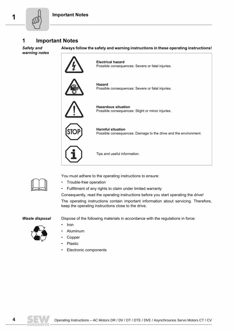
Always follow the safety and warning instructions in these operating instructions!
You must adhere to the operating instructions to ensure: Trouble-free operation Fulfillment of any rights to claim under limited warrantyConsequently, read the operating instructions before you start operating the drive!The operating instructions contain important information about servicing. Therefore,keep the operating instructions close to the drive.
Waste disposal Dispose of the following materials in accordance with the regulations in force: Iron Aluminum Copper Plastic Electronic components
Electrical hazardPossible consequences: Severe or fatal injuries.
Hazard Possible consequences: Severe or fatal injuries.
Hazardous situationPossible consequences: Slight or minor injuries.
Harmful situationPossible consequences: Damage to the drive and the environment.
Tips and useful information.
Operating Instructions – AC Motors DR / DV / DT / DTE / DVE / Asynchrounos Servo Motors CT / CV 5
2Safety Notes
2 Safety NotesPreface The following safety notes are concerned with the use of motors. If using gearmotors,
also refer to the safety notes for gear units in the corresponding operating instructions.Please also consider the supplementary safety notes in the individual sections ofthese operating instructions.
General information
During and after operation, motors and gearmotors have live and moving parts and theirsurfaces may be hot.All work related to transport, putting into storage, setting up/mounting,connection, startup, maintenance and repair may only be performed by trainedpersonnel observing The corresponding detailed operating instructions and wiring diagrams The warning and safety signs on the motor/gearmotor The specific regulations and requirements for the system The national / regional regulations governing safety and accident preventionSevere injuries and damage to property may result from Improper use Incorrect installation or operation Unauthorized removal of necessary protection covers or the housing
Designated use These electric motors are intended for industrial systems. They fulfill the applicablestandards and regulations: Low voltage directive 73/23/EECTechnical data and information about the permitted conditions can be found on thenameplate and in the documentation.It is essential to observe all the specified information!
Transportation Inspect the shipment for damage as soon as you receive the delivery. Inform theshipping company immediately. It may be necessary to preclude startup.Tighten installed eyebolts. They are only designed for the weight of themotor/gearmotor; do not attach any additional loads. The installed lifting eyebolts comply with DIN 580. Observe the loads and regula-tions specified in this standard. If the gearmotor is equipped with two suspensioneye lugs or lifting eyebolts, then both of the suspension eye lugs should be usedfor transportation. In this case, the tension force vector of the slings must notexceed a 45° angle in accordance with DIN 580. Use suitable, sufficiently rated handling equipment if necessary. Remove any transpor-tation fixtures prior to startup.
Installation / assembly
Follow the instructions in the section "Mechanical Installation"!
Inspection / maintenance
Follow the instructions in the section "Inspection and Maintenance"!
6 Operating Instructions – AC Motors DR / DV / DT / DTE / DVE / Asynchrounos Servo Motors CT / CV
3 Basic structure of AC motorsMotor Design
3 Motor Design
3.1 Basic structure of AC motors
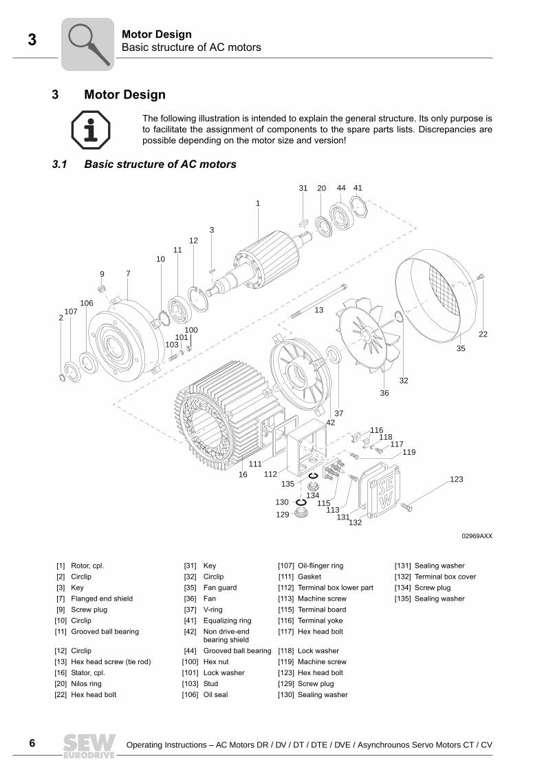
The following illustration is intended to explain the general structure. Its only purpose isto facilitate the assignment of components to the spare parts lists. Discrepancies arepossible depending on the motor size and version!
02969AXX
10
7
1112
1
20 44 41
16
42
36
35
37
32
13
22
132131
112111
129
130 115113
119
123
116118
117
2107
106
9
100101
103
3
31
135
134
[1] Rotor, cpl. [31] Key [107] Oil-flinger ring [131] Sealing washer[2] Circlip [32] Circlip [111] Gasket [132] Terminal box cover[3] Key [35] Fan guard [112] Terminal box lower part [134] Screw plug[7] Flanged end shield [36] Fan [113] Machine screw [135] Sealing washer[9] Screw plug [37] V-ring [115] Terminal board[10] Circlip [41] Equalizing ring [116] Terminal yoke[11] Grooved ball bearing [42] Non drive-end
bearing shield[117] Hex head bolt
[12] Circlip [44] Grooved ball bearing [118] Lock washer[13] Hex head screw (tie rod) [100] Hex nut [119] Machine screw[16] Stator, cpl. [101] Lock washer [123] Hex head bolt[20] Nilos ring [103] Stud [129] Screw plug[22] Hex head bolt [106] Oil seal [130] Sealing washer
Operating Instructions – AC Motors DR / DV / DT / DTE / DVE / Asynchrounos Servo Motors CT / CV 7
3Nameplate, unit designationMotor Design
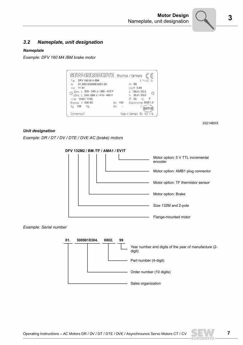
3.2 Nameplate, unit designationNameplateExample: DFV 160 M4 /BM brake motor
Unit designationExample: DR / DT / DV / DTE / DVE AC (brake) motors
Example: Serial number
03214BXX
DFV 132M2 / BM /TF / AMA1 / EV1T
Motor option: 5 V TTL incremental encoder
Motor option: AMB1 plug connector
Motor option: TF thermistor sensor
Motor option: Brake
Size 132M and 2-pole
Flange-mounted motor
01. 3009818304. 0002. 99
Year number end digits of the year of manufacture (2-digit)
Part number (4-digit)
Order number (10 digits)
Sales organization
8 Operating Instructions – AC Motors DR / DV / DT / DTE / DVE / Asynchrounos Servo Motors CT / CV
3 Nameplate, unit designationMotor Design
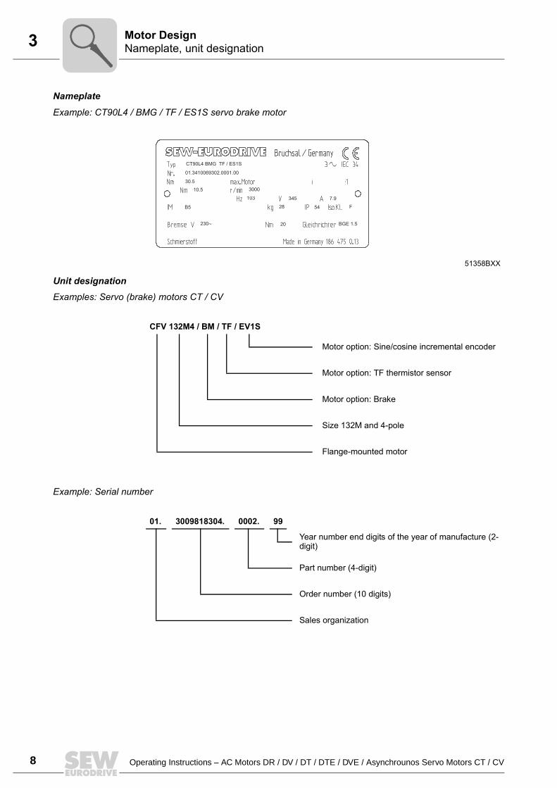
NameplateExample: CT90L4 / BMG / TF / ES1S servo brake motor
Unit designationExamples: Servo (brake) motors CT / CV
Example: Serial number
51358BXX
CT90L4 BMG TF / ES1S
01.3410069302.0001.00
30.5
3000 10.5
103 345 7.9
B5 28 54 F
230~ 20 BGE 1.5
CFV 132M4 / BM / TF / EV1S
Motor option: Sine/cosine incremental encoder
Motor option: TF thermistor sensor
Motor option: Brake
Size 132M and 4-pole
Flange-mounted motor
01. 3009818304. 0002. 99
Year number end digits of the year of manufacture (2-digit)
Part number (4-digit)
Order number (10 digits)
Sales organization
Operating Instructions – AC Motors DR / DV / DT / DTE / DVE / Asynchrounos Servo Motors CT / CV 9
4Before you beginMechanical Installation
4 Mechanical Installation
4.1 Before you beginThe drive may only be installed if
The entries on the nameplate of the drive and/or the output voltage of the frequencyinverter match the voltage supply system
The drive is undamaged (no damage caused by transportation or storage) It is certain that the following requirements have been met:
Ambient temperature between 20 °C and +40 °C1)
No oil, acid, gas, vapors, radiation, etc. Installation altitude max. 1000 m above sea level Note the restrictions for encoders Special versions: Drive configured in accordance with the ambient conditions
4.2 Preliminary workMotor shaft ends must be thoroughly cleaned of anti-corrosion agents, contamination orsimilar (use a commercially available solvent). Do not allow the solvent to penetrate thebearings or shaft seals this could cause material damage!
Extended storage of motors
Please note the reduced grease utilization period of the ball bearings after storageperiods exceeding one year.
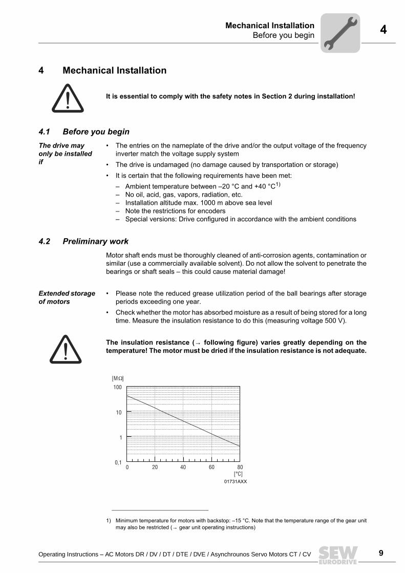
Check whether the motor has absorbed moisture as a result of being stored for a longtime. Measure the insulation resistance to do this (measuring voltage 500 V).
The insulation resistance (→ following figure) varies greatly depending on thetemperature! The motor must be dried if the insulation resistance is not adequate.
It is essential to comply with the safety notes in Section 2 during installation!
1) Minimum temperature for motors with backstop: 15 °C. Note that the temperature range of the gear unitmay also be restricted (→ gear unit operating instructions)
01731AXX
100
10
1
0,10 20 40 60 80
[°C]
[M ]
10 Operating Instructions – AC Motors DR / DV / DT / DTE / DVE / Asynchrounos Servo Motors CT / CV
4 Installing the motorMechanical Installation
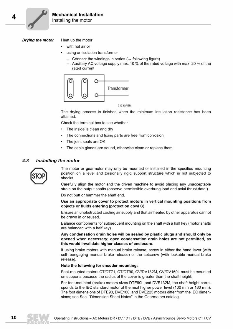
Drying the motor Heat up the motor with hot air or using an isolation transformer
Connect the windings in series (→ following figure) Auxiliary AC voltage supply max. 10 % of the rated voltage with max. 20 % of the
rated current
The drying process is finished when the minimum insulation resistance has beenattained.Check the terminal box to see whether The inside is clean and dry The connections and fixing parts are free from corrosion The joint seals are OK The cable glands are sound, otherwise clean or replace them.
4.3 Installing the motorThe motor or gearmotor may only be mounted or installed in the specified mountingposition on a level and torsionally rigid support structure which is not subjected toshocks.Carefully align the motor and the driven machine to avoid placing any unacceptablestrain on the output shafts (observe permissible overhung load and axial thrust data!).Do not butt or hammer the shaft end.Use an appropriate cover to protect motors in vertical mounting positions fromobjects or fluids entering (protection cowl C).Ensure an unobstructed cooling air supply and that air heated by other apparatus cannotbe drawn in or reused.Balance components for subsequent mounting on the shaft with a half key (motor shaftsare balanced with a half key).Any condensation drain holes will be sealed by plastic plugs and should only beopened when necessary; open condensation drain holes are not permitted, asthis would invalidate higher classes of enclosure.If using brake motors with manual brake release, screw in either the hand lever (withself-reengaging manual brake release) or the setscrew (with lockable manual brakerelease).Note the following for encoder mounting:Foot-mounted motors CT/DT71, CT/DT90, CV/DV132M, CV/DV160L must be mountedon supports because the radius of the cover is greater than the shaft height.For foot-mounted (brake) motors sizes DTE90L and DVE132M, the shaft height corre-sponds to the IEC standard motor of the next higher power level (100 mm or 160 mm).The foot dimensions of DTE90, DVE180, and DVE225 motors differ from the IEC dimen-sions; see Sec. "Dimension Sheet Notes" in the Gearmotors catalog.
01730AEN
Transformer
Operating Instructions – AC Motors DR / DV / DT / DTE / DVE / Asynchrounos Servo Motors CT / CV 11
4Installation tolerancesMechanical Installation
Installation in damp locations or in the open
If possible, arrange the terminal box so the cable entries are pointing downwards.Coat the threads of cable glands and pocket caps with sealant and tighten them well then coat them again.Seal the cable entry well.Thoroughly clean the sealing surfaces of terminal boxes and terminal box covers priorto reassembly; gaskets must be glued in on one side. Install new gaskets to replaceembrittled ones!Restore the anticorrosive coating if necessary.Check the enclosure.
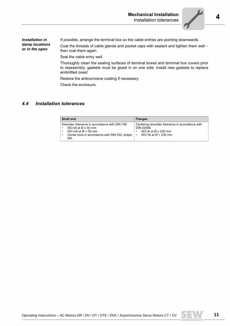
4.4 Installation tolerances
Shaft end Flanges
Diameter tolerance in accordance with DIN 748 ISO k6 at Ø ≤ 50 mm ISO m6 at Ø > 50 mm Center bore in accordance with DIN 332, shape
DR..
Centering shoulder tolerance in accordance with DIN 42948 ISO j6 at Ø ≤ 230 mm ISO h6 at Ø > 230 mm
12 Operating Instructions – AC Motors DR / DV / DT / DTE / DVE / Asynchrounos Servo Motors CT / CV
5 Wiring notesElectrical Installation
5 Electrical InstallationIt is essential to comply with the safety notes in section 2 during installation!Switch contacts in utilization category AC-3 to EN 60947-4-1 must be used forswitching the motor and the brake.
Using the wiring diagrams
The motor must only ever be connected as shown in the wiring diagram included withthe motor. Do not connect or start up the motor if this wiring diagram is missing.You can obtain the valid wiring diagram free of charge from SEW-EURODRIVE.
5.1 Wiring notesComply with the safety notes during installation.
Protecting brake control systems against interference
Do not route brake cables alongside switched-mode power cables, as otherwise thereis a risk of disrupting brake control systems.Switched-mode power cables include in particular: Output cables from frequency and servo controllers, converters, soft start units and
brake units Feeder cables for brake resistors and similar options
Protecting motor protection devices against interference
To protect SEW motor protection devices (temperature sensors TF, winding thermostatsTH) against interference: Route separately shielded feeder cables together with switched-mode power lines in
one cable Do not route unshielded feeder cables together with switched-mode power lines in
one cable
5.2 Special aspects for operation with a frequency inverterWhen motors are powered from inverters, you must adhere to the wiring instructionsissued by the inverter manufacturer. It is essential to observe the operating instructionsfor the frequency inverter.
5.3 Special aspects of single-phase motorsBear in mind that SEW single-phase motors are supplied without accessory equipmentsuch as capacitors, starting relays or centrifugal switches (exception: ET56L4 → Sec."Single-phase version ET56"). Any parts you need must be obtained from your dealerand connected according to the corresponding instructions and wiring diagrams.
Operating Instructions – AC Motors DR / DV / DT / DTE / DVE / Asynchrounos Servo Motors CT / CV 13
5Improving the grounding (EMC)Electrical Installation
5.4 Improving the grounding (EMC)For improved, low-impedance grounding at high frequencies, we recommend using thefollowing connections with the DR/DV/DT AC motors: Sizes DT71 ... DV 132S: [1] M5x10 thread rolling screw and 2 serrated lock washers
to DIN 6798 in the stator housing.
Sizes DV112M ... DV280: Screw and 2 serrated lock washers in the bore of the eyebolt.Thread size of the eye bolt: DV112 / 132S: M8 DV132M ... 180L: M12 DV200 ... 280: M16
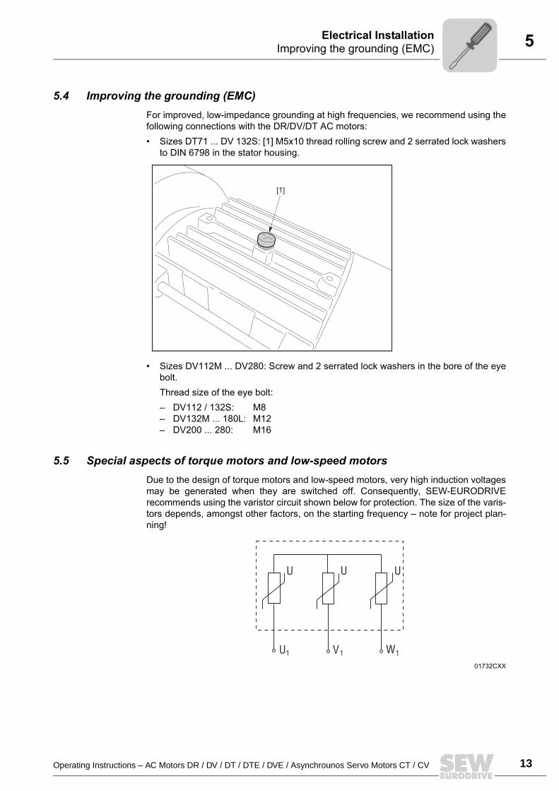
5.5 Special aspects of torque motors and low-speed motorsDue to the design of torque motors and low-speed motors, very high induction voltagesmay be generated when they are switched off. Consequently, SEW-EURODRIVErecommends using the varistor circuit shown below for protection. The size of the varis-tors depends, amongst other factors, on the starting frequency note for project plan-ning!
[1]
01732CXX
U
U1
U U
V1 W1
14 Operating Instructions – AC Motors DR / DV / DT / DTE / DVE / Asynchrounos Servo Motors CT / CV
5 Special aspects in switching operationElectrical Installation
5.6 Special aspects in switching operationWhen the motors are used in switching operation, possible interference of the switch-gear must be excluded by ensuring suitable wiring. According to EN 60204 (electricalequipment of machines), motor windings must have interference suppression to protectthe numerical or programmable logic controllers. As it is primarily switching operationsthat cause interference, SEW-EURODRIVE recommends installing protective circuitryin the switching devices.
5.7 Environmental conditions during operationAmbient temperature
The temperature range of -20 °C to +40 °C must be ensured unless specified otherwiseon the nameplate. Motors intended for use in higher or lower ambient temperatures havethe appropriate designation on the nameplate.
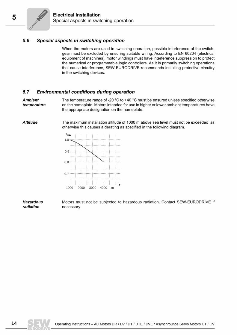
Altitude The maximum installation altitude of 1000 m above sea level must not be exceeded asotherwise this causes a derating as specified in the following diagram.
Hazardous radiation
Motors must not be subjected to hazardous radiation. Contact SEW-EURODRIVE ifnecessary.
1000 2000 3000 4000 m
0.7
0.8
0.9
1.0
fH
Operating Instructions – AC Motors DR / DV / DT / DTE / DVE / Asynchrounos Servo Motors CT / CV 15
5Connecting the motorElectrical Installation
5.8 Connecting the motor
Connecting the motor via terminal boxes
According to the circuit diagram provided Check the line cross section Arrange terminal links correctly Screw connections and protective earth conductors on firmly In terminal boxes: Check winding connections and tighten them if necessary
Small connection accessories
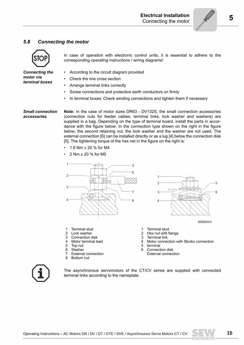
Note: In the case of motor sizes DR63 - DV132S, the small connection accessories(connection nuts for feeder cables, terminal links, lock washer and washers) aresupplied in a bag. Depending on the type of terminal board, install the parts in accor-dance with the figure below. In the connection type shown on the right in the figurebelow, the second retaining nut, the lock washer and the washer are not used. Theexternal connection [6] can be installed directly or as a lug [4] below the connection disk[5]. The tightening torque of the hex net in the figure on the right is: 1.6 Nm ± 20 % for M4 2 Nm ± 20 % for M5
In case of operation with electronic control units, it is essential to adhere to thecorresponding operating instructions / wiring diagrams!
50926AXX
12345678
Terminal studLock washerConnection diskMotor terminal leadTop nutWasherExternal connectionBottom nut
123456
Terminal studHex nut with flangeTerminal linkMotor connection with Stocko connection terminalConnection diskExternal connection
1
1
2
3
4
5
6
2
3
4
5
6
7
8
The asynchronous servomotors of the CT/CV series are supplied with connectedterminal links according to the nameplate.
16 Operating Instructions – AC Motors DR / DV / DT / DTE / DVE / Asynchrounos Servo Motors CT / CV
5 Preparing motor sizes 56 and 63 knockoutElectrical Installation
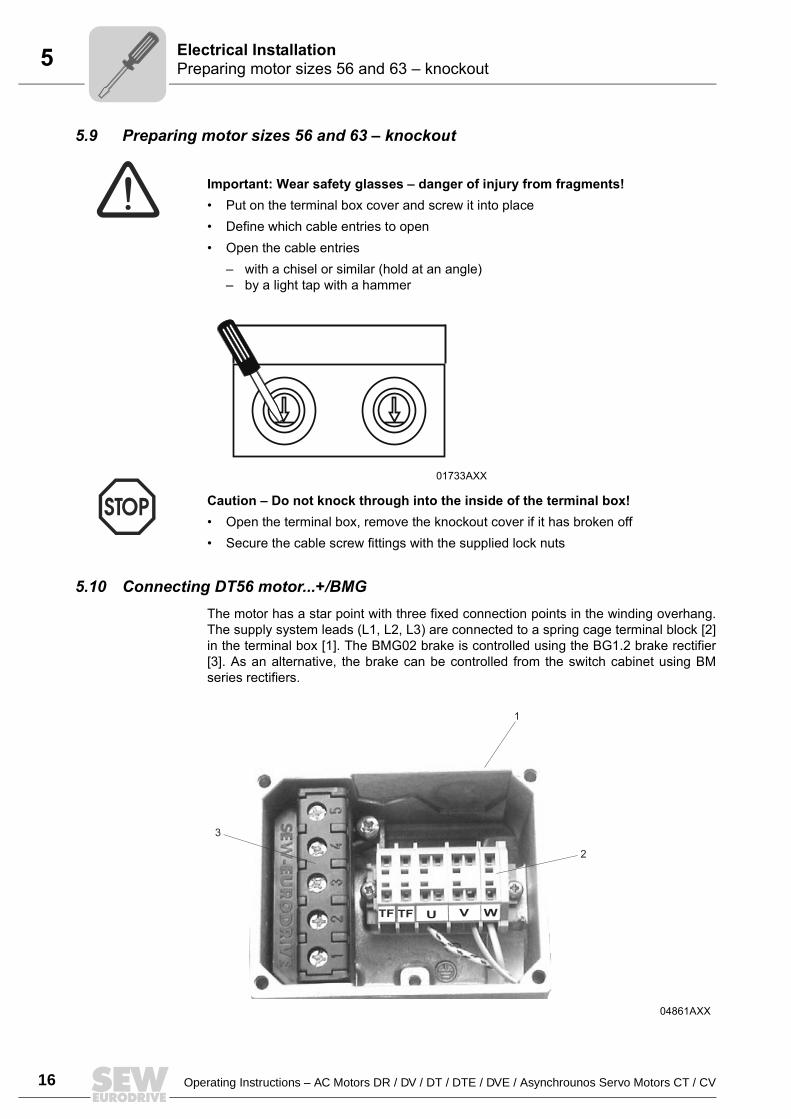
5.9 Preparing motor sizes 56 and 63 knockout
Important: Wear safety glasses danger of injury from fragments! Put on the terminal box cover and screw it into place Define which cable entries to open Open the cable entries
with a chisel or similar (hold at an angle) by a light tap with a hammer
Caution Do not knock through into the inside of the terminal box! Open the terminal box, remove the knockout cover if it has broken off Secure the cable screw fittings with the supplied lock nuts
5.10 Connecting DT56 motor...+/BMGThe motor has a star point with three fixed connection points in the winding overhang.The supply system leads (L1, L2, L3) are connected to a spring cage terminal block [2]in the terminal box [1]. The BMG02 brake is controlled using the BG1.2 brake rectifier[3]. As an alternative, the brake can be controlled from the switch cabinet using BMseries rectifiers.
01733AXX
04861AXX
V WUTF TF
1
2
3
Operating Instructions – AC Motors DR / DV / DT / DTE / DVE / Asynchrounos Servo Motors CT / CV 17
5Single-phase version ET56Electrical Installation
5.11 Single-phase version ET56The ET56 single-phase motor is supplied with a running capacitor that is mounted andconnected:1~230 V, 50 Hz CB = 4 µF1~230 V, 60 Hz CB = 4 µF1~110 V, 60 Hz CB = 20 µF
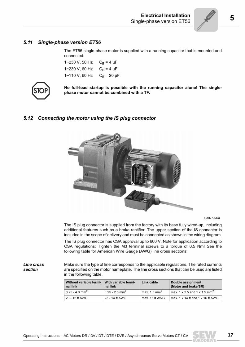
5.12 Connecting the motor using the IS plug connector
The IS plug connector is supplied from the factory with its base fully wired-up, includingadditional features such as a brake rectifier. The upper section of the IS connector isincluded in the scope of delivery and must be connected as shown in the wiring diagram.The IS plug connector has CSA approval up to 600 V. Note for application according toCSA regulations: Tighten the M3 terminal screws to a torque of 0.5 Nm! See thefollowing table for American Wire Gauge (AWG) line cross sections!
Line cross section
Make sure the type of line corresponds to the applicable regulations. The rated currentsare specified on the motor nameplate. The line cross sections that can be used are listedin the following table.
No full-load startup is possible with the running capacitor alone! The single-phase motor cannot be combined with a TF.
03075AXX
Without variable termi-nal link
With variable termi-nal link
Link cable Double assignment(Motor and brake/SR)
0.25 - 4.0 mm2 0.25 - 2.5 mm2 max. 1.5 mm2 max. 1 x 2.5 and 1 x 1.5 mm2
23 - 12 # AWG 23 - 14 # AWG max. 16 # AWG max. 1 x 14 # and 1 x 16 # AWG
18 Operating Instructions – AC Motors DR / DV / DT / DTE / DVE / Asynchrounos Servo Motors CT / CV
5 Connecting the motor using the IS plug connectorElectrical Installation
Wiring the upper section of the plug connection
Loosen the housing cover screws Remove the housing cover
Remove the screws from the upper section of the plug connector Remove the upper section of the plug connector from the cover
Strip the insulation off the connection lead Strip about 9 mm insulation off the connecting leads
Pass the cable through the cable gland
Wiring up as shown in circuit diagram DT82, DT83
Connect the lines as shown in the circuit diagram Tighten the clamping screws carefully!
Install the plug connector (→ Sec. "Installing the plug connector")
Wiring up as shown in wiring diagram DT81
For / startup: Connect with 6 lines
Tighten the clamping screws carefully! Motor contactors in the switch cabinet
Install the plug connector (→ Sec. "Installing the plug connector")
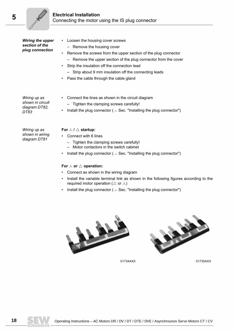
For or operation: Connect as shown in the wiring diagram Install the variable terminal link as shown in the following figures according to the
required motor operation ( or ) Install the plug connector (→ Sec. "Installing the plug connector")
01734AXX 01735AXX
Operating Instructions – AC Motors DR / DV / DT / DTE / DVE / Asynchrounos Servo Motors CT / CV 19
5Connecting the motor using the IS plug connectorElectrical Installation
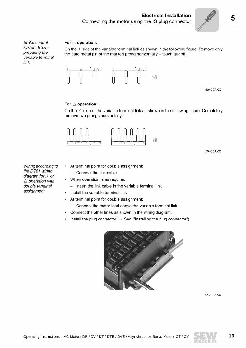
Brake control system BSR preparing the variable terminal link
For operation:On the side of the variable terminal link as shown in the following figure: Remove onlythe bare metal pin of the marked prong horizontally touch guard!
For operation:On the side of the variable terminal link as shown in the following figure: Completelyremove two prongs horizontally.
Wiring according to the DT81 wiring diagram for or operation with double terminal assignment
At terminal point for double assignment: Connect the link cable
When operation is as required: Insert the link cable in the variable terminal link
Install the variable terminal link At terminal point for double assignment:
Connect the motor lead above the variable terminal link Connect the other lines as shown in the wiring diagram. Install the plug connector (→ Sec. "Installing the plug connector")
50429AXX
50430AXX
01738AXX
20 Operating Instructions – AC Motors DR / DV / DT / DTE / DVE / Asynchrounos Servo Motors CT / CV
5 Connecting the motor using the IS plug connectorElectrical Installation
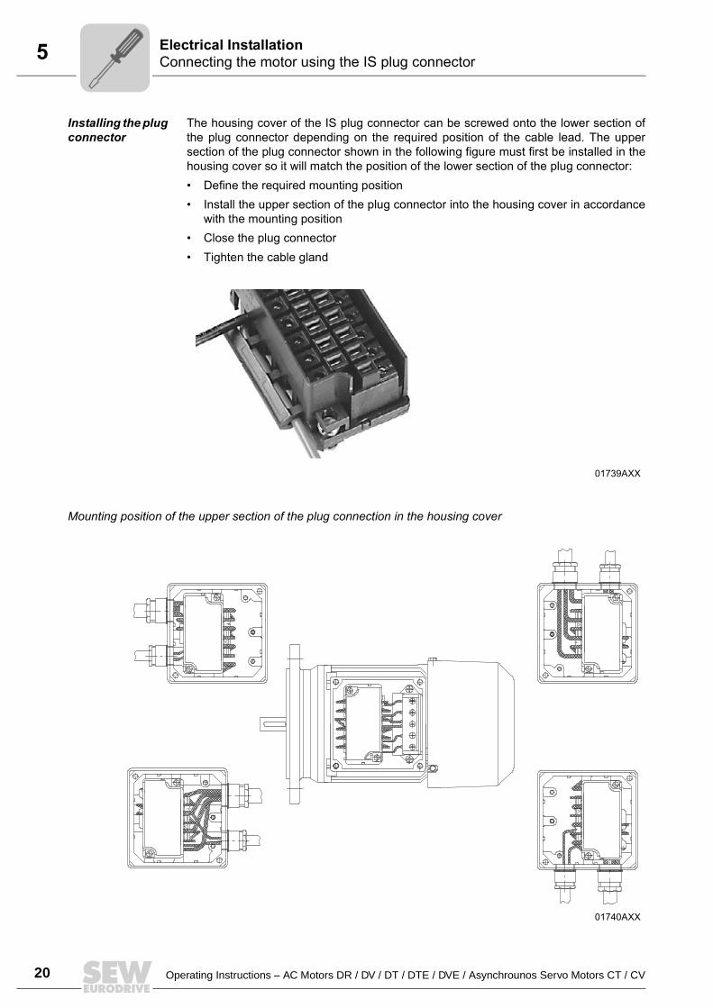
Installing the plug connector
The housing cover of the IS plug connector can be screwed onto the lower section ofthe plug connector depending on the required position of the cable lead. The uppersection of the plug connector shown in the following figure must first be installed in thehousing cover so it will match the position of the lower section of the plug connector: Define the required mounting position Install the upper section of the plug connector into the housing cover in accordance
with the mounting position Close the plug connector Tighten the cable gland
Mounting position of the upper section of the plug connection in the housing cover
01739AXX
01740AXX
Operating Instructions – AC Motors DR / DV / DT / DTE / DVE / Asynchrounos Servo Motors CT / CV 21
5Connect the motor using plug connectors AB.., AD.., AM.., ASElectrical Installation
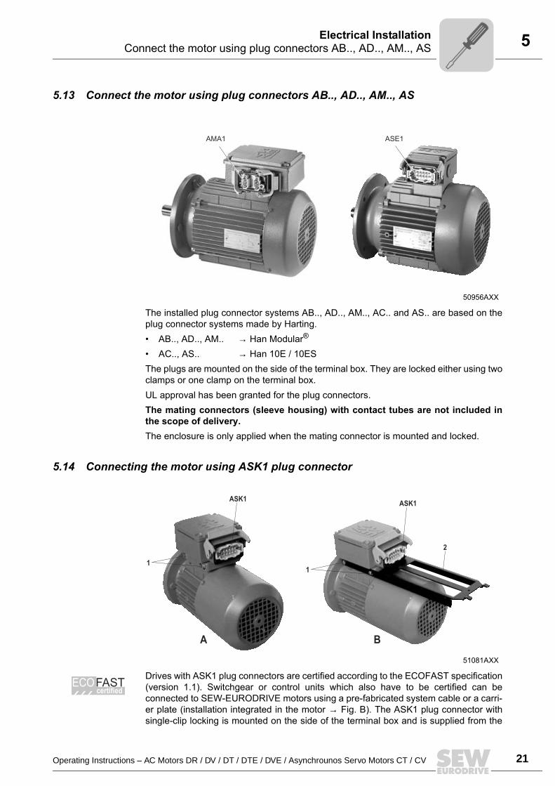
5.13 Connect the motor using plug connectors AB.., AD.., AM.., AS
The installed plug connector systems AB.., AD.., AM.., AC.. and AS.. are based on theplug connector systems made by Harting. AB.., AD.., AM.. → Han Modular®
AC.., AS.. → Han 10E / 10ESThe plugs are mounted on the side of the terminal box. They are locked either using twoclamps or one clamp on the terminal box.UL approval has been granted for the plug connectors.The mating connectors (sleeve housing) with contact tubes are not included inthe scope of delivery.The enclosure is only applied when the mating connector is mounted and locked.
5.14 Connecting the motor using ASK1 plug connector
Drives with ASK1 plug connectors are certified according to the ECOFAST specification(version 1.1). Switchgear or control units which also have to be certified can beconnected to SEW-EURODRIVE motors using a pre-fabricated system cable or a carri-er plate (installation integrated in the motor → Fig. B). The ASK1 plug connector withsingle-clip locking is mounted on the side of the terminal box and is supplied from the
50956AXX
AMA1 ASE1
51081AXX
ASK1
A B
ASK1
2
11
ECOcertifiedFAST
22 Operating Instructions – AC Motors DR / DV / DT / DTE / DVE / Asynchrounos Servo Motors CT / CV
5 Connecting the motor using ASK1 plug connectorElectrical Installation
factory fully wired up, including additional features such as a brake rectifier.
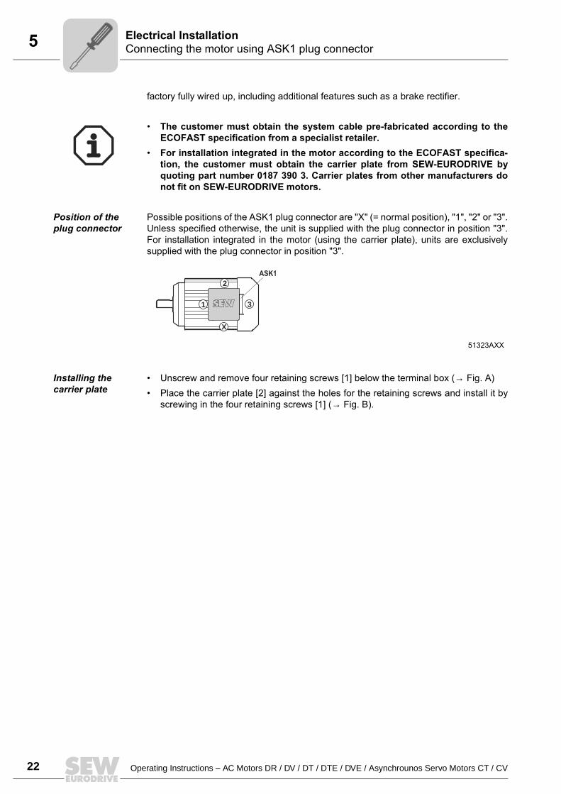
Position of the plug connector
Possible positions of the ASK1 plug connector are "X" (= normal position), "1", "2" or "3".Unless specified otherwise, the unit is supplied with the plug connector in position "3".For installation integrated in the motor (using the carrier plate), units are exclusivelysupplied with the plug connector in position "3".
Installing the carrier plate
Unscrew and remove four retaining screws [1] below the terminal box (→ Fig. A) Place the carrier plate [2] against the holes for the retaining screws and install it by
screwing in the four retaining screws [1] (→ Fig. B).
The customer must obtain the system cable pre-fabricated according to theECOFAST specification from a specialist retailer.
For installation integrated in the motor according to the ECOFAST specifica-tion, the customer must obtain the carrier plate from SEW-EURODRIVE byquoting part number 0187 390 3. Carrier plates from other manufacturers donot fit on SEW-EURODRIVE motors.
51323AXX
1
X
3
2ASK1
Operating Instructions – AC Motors DR / DV / DT / DTE / DVE / Asynchrounos Servo Motors CT / CV 23
5Connecting the brakeElectrical Installation
5.15 Connecting the brakeThe brake is released electrically. The brake is applied mechanically when the voltageis switched off.
Connect the brake according to the wiring diagram supplied with the brake. Note:In view of the DC voltage to be switched and the high level of current load, it is
essential to use either special brake contactors or AC contactors with contacts inutilization category AC-3 to EN 60947-4-1.
Attach one of the following options for the version with manual brake release Hand lever (for self-reengaging manual brake release) Setscrew (for locking manual brake release)
After replacing the brake disc, the maximum braking torque is reached only after sev-eral cycles.
Connecting the brake control system
The DC disk brake is powered from a brake control system with a protection circuit. It islocated in the terminal box / IS lower part or must be installed in the switch cabinet (→Sec. "Wiring notes").
Check the line cross sections - braking currents (→ Sec. "Technical Data") Connect the brake control system according to the wiring diagram supplied with the
brake For motors in thermal class H, install the brake rectifier in the switch cabinet!
Comply with the applicable regulations issued by the relevant employer's liabilityinsurance association regarding phase failure protection and the associatedcircuit/circuit modification!
24 Operating Instructions – AC Motors DR / DV / DT / DTE / DVE / Asynchrounos Servo Motors CT / CV
5 Accessory equipmentElectrical Installation
5.16 Accessory equipment
Connect supplied accessory equipment according to the wiring diagrams included.
TF temperature sensor
The positive temperature coefficient (PTC) thermistors comply with DIN 44082.Resistance measurement (measuring instrument with V ≤ 2.5 V or I < 1 mA): Standard measured values: 20...500 Ω, thermal resistance > 4000 Ω Measured values pole-changing with separate winding: 40...1000 Ω,
Thermal resistance > 4000 Ω
TH winding thermostatsThe thermostats are connected in series as standard and open when the permittedwinding temperature is exceeded. They can be connected in the drive monitoring loop.
Forced cooling fanMotor sizes 71 - 132S
Do not apply voltage!
When using the temperature sensor for thermal monitoring, the evaluation function mustbe activated to maintain reliable isolation of the temperature sensor circuit. If thetemperature reaches an excessive level, the thermal protection function must beeffective immediately.
VAC VDC
Voltage U [V] 250 400 60 24
Current (cos ϕ = 1.0) [A]
2.5 0.75 1.0 1.6
Current (cos ϕ = 0.6) [A]
1.6 0.5
Contact resistance max. 1 ohm at 5 V = / 1 mA
VS system 1 x 230 VAC, 50 Hz Connection in separate terminal box Max. connection cross section 3 x 1.5 mm2
Cable screw fitting M16x1.5
Refer to the VS wiring diagram for information about connecting the VS forced coolingfan (order number: 0975 8385).
Operating Instructions – AC Motors DR / DV / DT / DTE / DVE / Asynchrounos Servo Motors CT / CV 25
5Accessory equipmentElectrical Installation
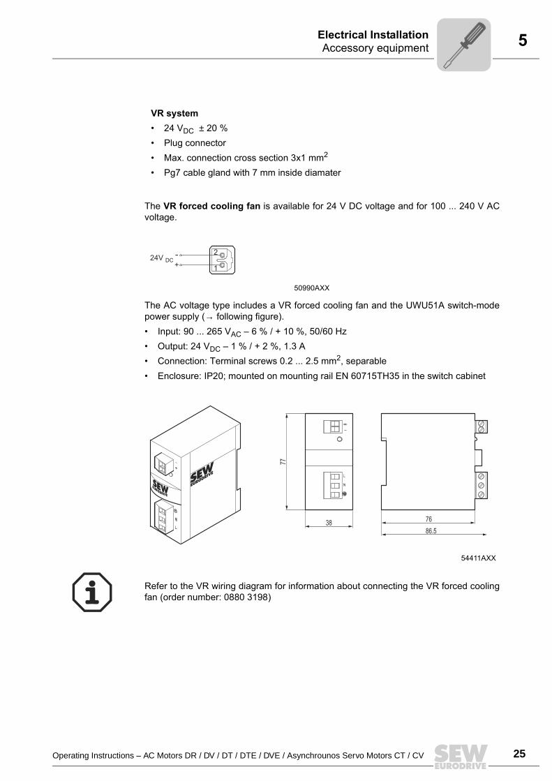
The VR forced cooling fan is available for 24 V DC voltage and for 100 ... 240 V ACvoltage.
The AC voltage type includes a VR forced cooling fan and the UWU51A switch-modepower supply (→ following figure). Input: 90 ... 265 VAC 6 % / + 10 %, 50/60 Hz Output: 24 VDC 1 % / + 2 %, 1.3 A Connection: Terminal screws 0.2 ... 2.5 mm2, separable Enclosure: IP20; mounted on mounting rail EN 60715TH35 in the switch cabinet
VR system 24 VDC ± 20 % Plug connector Max. connection cross section 3x1 mm2
Pg7 cable gland with 7 mm inside diamater
50990AXX
54411AXX
1
2-+
24V DC
77
3886.5
76
Refer to the VR wiring diagram for information about connecting the VR forced coolingfan (order number: 0880 3198)
26 Operating Instructions – AC Motors DR / DV / DT / DTE / DVE / Asynchrounos Servo Motors CT / CV
5 Accessory equipmentElectrical Installation
Motor size 132M - 280
A transformer may be present in the VS system to adapt to a voltage other than thestandard. The VS and V systems are also available for 60 Hz.
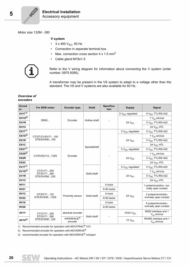
Overview of encoders
V system 3 x 400 VAC, 50 Hz Connection in separate terminal box Max. connection cross section 4 x 1.5 mm2
Cable gland M16x1.5
Refer to the V wiring diagram for information about connecting the V system (ordernumber: 0975 8385).
Encoder For SEW motor Encoder type Shaft Specifica-
tion Supply Signal
EH1T1)
DR63... Encoder Hollow shaft -
5 VDC regulated 5 VDC TTL/RS-422
EH1S2)
24 VDC
1 Vss sin/cos
EH1R 5 VDC TTL/RS-422
EH1C 24 VDC HTL
ES1T1)
CT/DT/CV/DV71...100DTE/DVE90...100
Encoder
Spreadshaft
-
5 VDC regulated 5 VDC TTL/RS-422
ES1S2)
24 VDC
1 Vss sin/cos
ES1R 5 VDC TTL/RS-422
ES1C 24 VDC HTL
ES2T1)
CV/DV(E)112...132S
5 VDC regulated 5 VDC TTL/RS-422
ES2S2)
24 VDC
1 Vss sin/cos
ES2R 5 VDC TTL/RS-422
ES2C 24 VDC HTL
EV1T1)
CT/CV71...200DT/DV71...280
DTE/DVE90...225Solid shaft
5 VDC regulated 5 VDC TTL/RS-422
EV1S2)
24 VDC
1 Vss sin/cos
EV1R 5 VDC TTL/RS-422
EV1C 24 VDC HTL
NV11
DT/DV71...132DTE/DVE90...132S Proximity sensor Solid shaft
A track
24 VDC
1 pulse/revolution, nor-mally open contactNV21 A+B tracks
NV12 A track 2 pulses/revolution, normally open contactNV22 A+B tracks
NV16 A track 6 pulses/revolution, normally open contactNV26 A+B tracks
AV1Y CT/CV71...200DT/DV71...280
DTE/DVE90...225
absolute encoderSolid shaft -
15/24 VDCMSSI interface and 1
Vss sin/cos
AV1H3) HIPERFACE® encoder 12 VDC
RS485 interface and 1 Vss sin/cos
1) Recommended encoder for operation with MOVITRAC® 31C2) Recommended encoder for operation with MOVIDRIVE®
3) recommended encoder for operation with MOVIDRIVE® compact
Operating Instructions – AC Motors DR / DV / DT / DTE / DVE / Asynchrounos Servo Motors CT / CV 27
5Accessory equipmentElectrical Installation
Refer to the following wiring diagrams for information about connectingES1./ES2./EV1./EH1. encoders and AV1Y and AV1H absolute encoders: Wiring diagrams for ES1./ES2./EV1./EH1. encoders: Order number 0918 6832 Wiring diagram AV1Y absolute encoder: Order number 0918 6808 Wiring diagram AV1H absolute encoder: Order number 1052 9705
Encoder connection
When connecting the encoders to the inverters, always follow the operating instructionsfor the relevant inverter! Maximum line length (inverter - encoder):
100 m with a capacitance per unit length ≤ 120 nF/km Core cross section: 0,20 ... 0.5 mm2
Use a shielded cable with twisted pairs of insulated conductors (exception: cable forHTL sensor) and connect the shield over a large surface area at both ends: to the encoder in the cable gland or in the encoder plug to the inverter on the electronics shield clamp or to the housing of the sub D plug
Install the encoder cables separately from the power cables, maintaining a distanceof at least 200 mm.
Maximum oscillation load for encoder ≤ 10 g ≈ 100 m/s2 (10 Hz ... 2 kHz) Shock resistance ≤ 100 g ≈ 1000 m/s2
00
I
28 Operating Instructions – AC Motors DR / DV / DT / DTE / DVE / Asynchrounos Servo Motors CT / CV
6 Prerequisites for startupStartup
6 Startup6.1 Prerequisites for startup
Before startup, make sure that
The drive is undamaged and not blocked The measures stipulated in the "Preliminary work" section are performed after
extended storage All connections have been made properly The direction of rotation of the motor/gearmotor is correct
(motor rotating clockwise: U, V, W to L1, L2, L3) All protective covers have been fitted correctly All motor protection equipment is active and set for the rated motor current The self-reengaging manual brake release is used in case of hoist drives There are no other sources of danger present
During startup, make sure that
The motor is running correctly (no overload, no speed fluctuation, no loud noises,etc.)
The correct braking torque is set according to the specific application (→ Sec. "Tech-nical Data")
In case of problems (→ Sec. "Malfunctions")
It is essential to comply with the safety notes in Sec. 2 during startup!
In brake motors with self-reengaging manual brake release, the manual brakerelease lever must be removed after startup. A bracket is provided for storing thelever on the outside of the motor.
00
I
Operating Instructions – AC Motors DR / DV / DT / DTE / DVE / Asynchrounos Servo Motors CT / CV 29
6Altering the blocking direction on motors with a backstopStartup
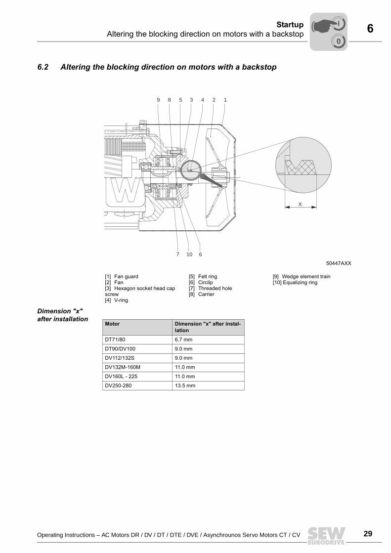
6.2 Altering the blocking direction on motors with a backstop
Dimension "x" after installation
50447AXX
[1] Fan guard[2] Fan[3] Hexagon socket head cap screw[4] V-ring
[5] Felt ring[6] Circlip[7] Threaded hole[8] Carrier
[9] Wedge element train[10] Equalizing ring
6107
1243589
X
Motor Dimension "x" after instal-lation
DT71/80 6.7 mm
DT90/DV100 9.0 mm
DV112/132S 9.0 mm
DV132M-160M 11.0 mm
DV160L - 225 11.0 mm
DV250-280 13.5 mm
00
I
30 Operating Instructions – AC Motors DR / DV / DT / DTE / DVE / Asynchrounos Servo Motors CT / CV
6 Altering the blocking direction on motors with a backstopStartup
Do not start up the motor in the blocking direction (note the phase angle whenconnecting). Note the direction of rotation of the output shaft and the number of stageswhen mounting the motor on a gear unit. The backstop can be operated once in theblocking direction at half the motor voltage for checking purposes.1. Isolate the motor from the supply, safeguarding it against unintentional power-
up.2. Remove fan guard [1] and fan [2], unscrew hexagon socket head cap screws [3]3. Remove the V-ring [4] and sealing flange with felt ring [5]. (Collect the grease for
subsequent use.)4. Remove the circlip [6] (not for DT71/80); for DV132M-160M, also remove the
equalizing rings [10].5. Pull the carrier [8] and wedge element train [9] completely off the threaded holes [7],
turn them by 180° and press them back on.6. Refill the grease.7. Important: Do not exert pressure on or hit the wedge element train danger of
damaging the material!8. During the press-in operation shortly before the wedge element penetrates the
locking collar slowly turn the rotor shaft by hand in the direction of rotation. Thisallows the wedge element to slide into the locking collar more easily.
9. Install the remaining parts of the backstop by following steps 4. to 2. in reverse order.Note the installation dimension "x" for the V-ring [4].
00
I
Operating Instructions – AC Motors DR / DV / DT / DTE / DVE / Asynchrounos Servo Motors CT / CV 31
7Motor MalfunctionsMalfunctions
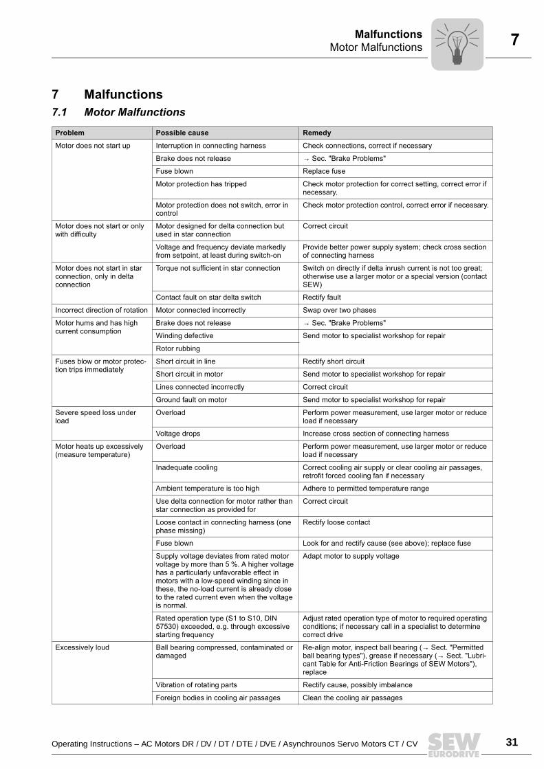
7 Malfunctions7.1 Motor Malfunctions
Problem Possible cause Remedy
Motor does not start up Interruption in connecting harness Check connections, correct if necessary
Brake does not release → Sec. "Brake Problems"
Fuse blown Replace fuse
Motor protection has tripped Check motor protection for correct setting, correct error if necessary.
Motor protection does not switch, error in control
Check motor protection control, correct error if necessary.
Motor does not start or only with difficulty
Motor designed for delta connection but used in star connection
Correct circuit
Voltage and frequency deviate markedly from setpoint, at least during switch-on
Provide better power supply system; check cross section of connecting harness
Motor does not start in star connection, only in delta connection
Torque not sufficient in star connection Switch on directly if delta inrush current is not too great; otherwise use a larger motor or a special version (contact SEW)
Contact fault on star delta switch Rectify fault
Incorrect direction of rotation Motor connected incorrectly Swap over two phases
Motor hums and has high current consumption
Brake does not release → Sec. "Brake Problems"
Winding defective Send motor to specialist workshop for repair
Rotor rubbing
Fuses blow or motor protec-tion trips immediately
Short circuit in line Rectify short circuit
Short circuit in motor Send motor to specialist workshop for repair
Lines connected incorrectly Correct circuit
Ground fault on motor Send motor to specialist workshop for repair
Severe speed loss under load
Overload Perform power measurement, use larger motor or reduce load if necessary
Voltage drops Increase cross section of connecting harness
Motor heats up excessively (measure temperature)
Overload Perform power measurement, use larger motor or reduce load if necessary
Inadequate cooling Correct cooling air supply or clear cooling air passages, retrofit forced cooling fan if necessary
Ambient temperature is too high Adhere to permitted temperature range
Use delta connection for motor rather than star connection as provided for
Correct circuit
Loose contact in connecting harness (one phase missing)
Rectify loose contact
Fuse blown Look for and rectify cause (see above); replace fuse
Supply voltage deviates from rated motor voltage by more than 5 %. A higher voltage has a particularly unfavorable effect in motors with a low-speed winding since in these, the no-load current is already close to the rated current even when the voltage is normal.
Adapt motor to supply voltage
Rated operation type (S1 to S10, DIN 57530) exceeded, e.g. through excessive starting frequency
Adjust rated operation type of motor to required operating conditions; if necessary call in a specialist to determine correct drive
Excessively loud Ball bearing compressed, contaminated or damaged
Re-align motor, inspect ball bearing (→ Sect. "Permitted ball bearing types"), grease if necessary (→ Sect. "Lubri-cant Table for Anti-Friction Bearings of SEW Motors"), replace
Vibration of rotating parts Rectify cause, possibly imbalance
Foreign bodies in cooling air passages Clean the cooling air passages
32 Operating Instructions – AC Motors DR / DV / DT / DTE / DVE / Asynchrounos Servo Motors CT / CV
7 Brake problemsMalfunctions
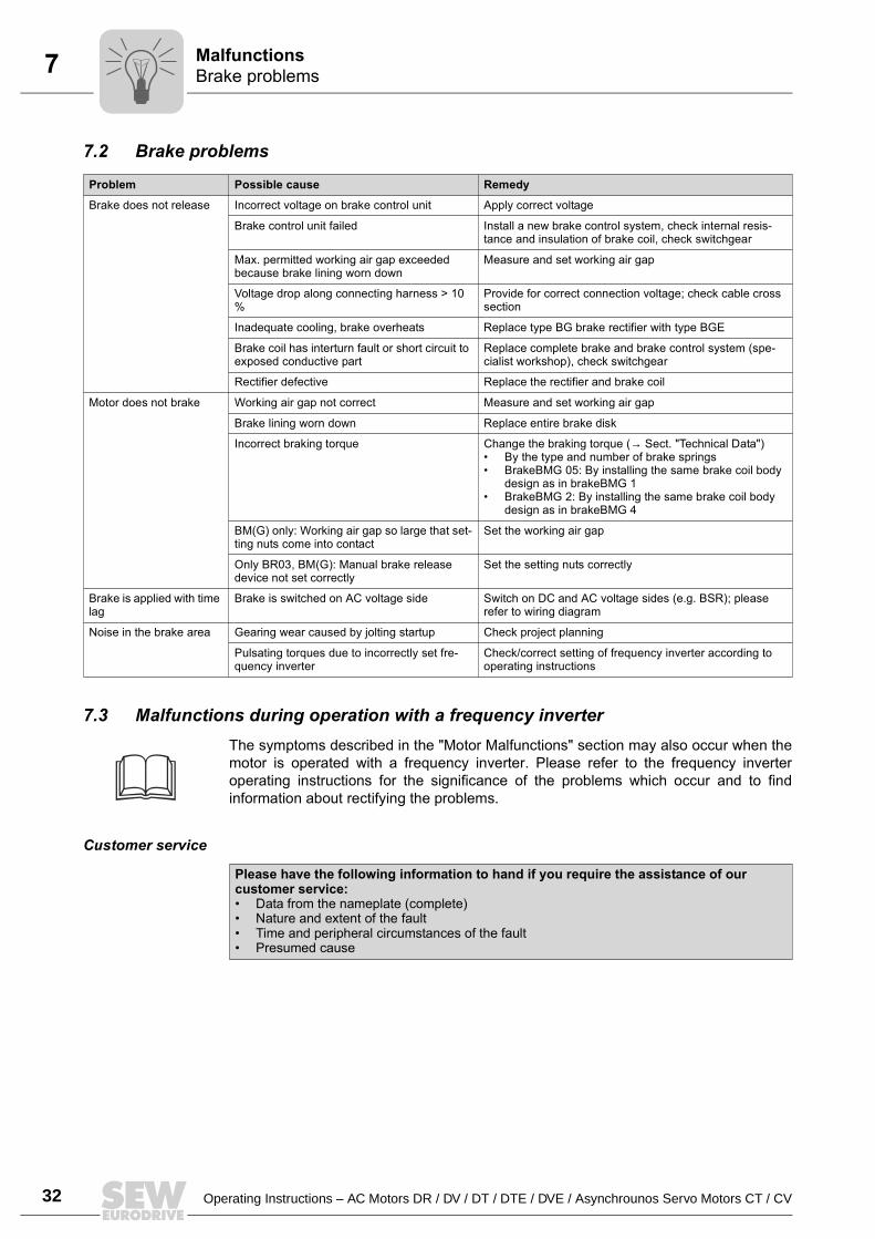
7.2 Brake problems
7.3 Malfunctions during operation with a frequency inverterThe symptoms described in the "Motor Malfunctions" section may also occur when themotor is operated with a frequency inverter. Please refer to the frequency inverteroperating instructions for the significance of the problems which occur and to findinformation about rectifying the problems.
Customer service
Problem Possible cause Remedy
Brake does not release Incorrect voltage on brake control unit Apply correct voltage
Brake control unit failed Install a new brake control system, check internal resis-tance and insulation of brake coil, check switchgear
Max. permitted working air gap exceeded because brake lining worn down
Measure and set working air gap
Voltage drop along connecting harness > 10 %
Provide for correct connection voltage; check cable cross section
Inadequate cooling, brake overheats Replace type BG brake rectifier with type BGE
Brake coil has interturn fault or short circuit to exposed conductive part
Replace complete brake and brake control system (spe-cialist workshop), check switchgear
Rectifier defective Replace the rectifier and brake coil
Motor does not brake Working air gap not correct Measure and set working air gap
Brake lining worn down Replace entire brake disk
Incorrect braking torque Change the braking torque (→ Sect. "Technical Data") By the type and number of brake springs BrakeBMG 05: By installing the same brake coil body
design as in brakeBMG 1 BrakeBMG 2: By installing the same brake coil body
design as in brakeBMG 4
BM(G) only: Working air gap so large that set-ting nuts come into contact
Set the working air gap
Only BR03, BM(G): Manual brake release device not set correctly
Set the setting nuts correctly
Brake is applied with time lag
Brake is switched on AC voltage side Switch on DC and AC voltage sides (e.g. BSR); please refer to wiring diagram
Noise in the brake area Gearing wear caused by jolting startup Check project planning
Pulsating torques due to incorrectly set fre-quency inverter
Check/correct setting of frequency inverter according to operating instructions
Please have the following information to hand if you require the assistance of our customer service: Data from the nameplate (complete) Nature and extent of the fault Time and peripheral circumstances of the fault Presumed cause
Operating Instructions – AC Motors DR / DV / DT / DTE / DVE / Asynchrounos Servo Motors CT / CV 33
8Inspection and maintenance intervalsInspection / Maintenance
8 Inspection / Maintenance Use only genuine spare parts in accordance with the valid parts list! Always install a new brake control system at the same time as replacing the brake
coil! Motors can become very hot during operation danger of burns! Secure hoist drives or lower them (danger of falling). Isolate the motor and brake from the supply before starting work, safeguarding them
against unintentional power-up!
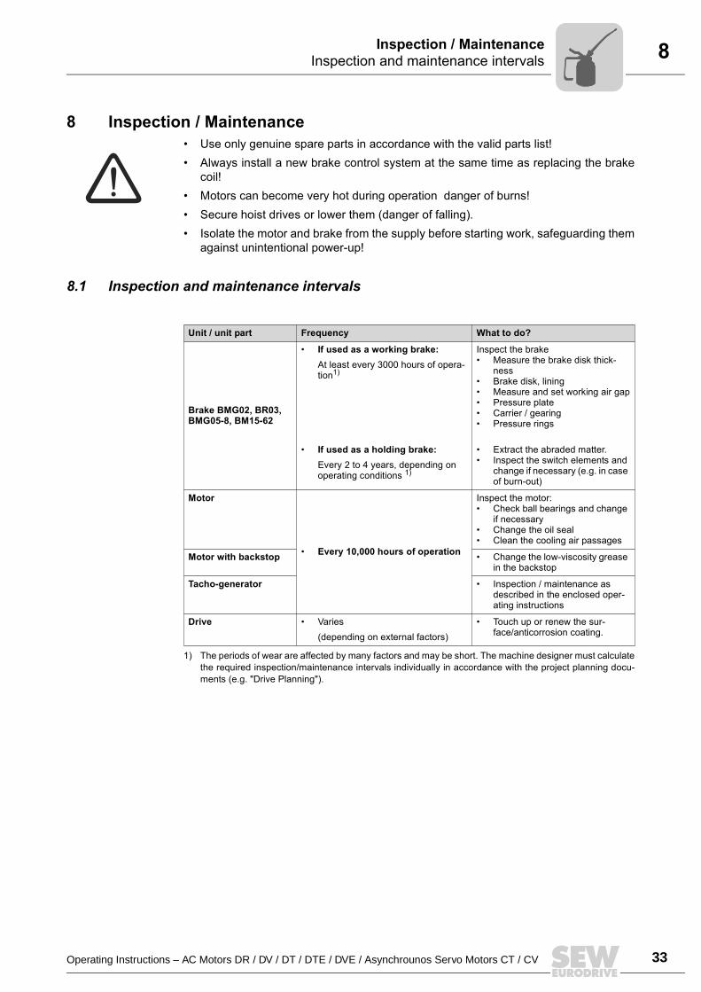
8.1 Inspection and maintenance intervals
Unit / unit part Frequency What to do?
Brake BMG02, BR03, BMG05-8, BM15-62
If used as a working brake:At least every 3000 hours of opera-tion1)
If used as a holding brake:Every 2 to 4 years, depending on operating conditions 1)
1) The periods of wear are affected by many factors and may be short. The machine designer must calculatethe required inspection/maintenance intervals individually in accordance with the project planning docu-ments (e.g. "Drive Planning").
Inspect the brake Measure the brake disk thick-
ness Brake disk, lining Measure and set working air gap Pressure plate Carrier / gearing Pressure rings
Extract the abraded matter. Inspect the switch elements and
change if necessary (e.g. in case of burn-out)
Motor
Every 10,000 hours of operation
Inspect the motor: Check ball bearings and change
if necessary Change the oil seal Clean the cooling air passages
Motor with backstop Change the low-viscosity grease in the backstop
Tacho-generator Inspection / maintenance as described in the enclosed oper-ating instructions
Drive Varies(depending on external factors)
Touch up or renew the sur-face/anticorrosion coating.
34 Operating Instructions – AC Motors DR / DV / DT / DTE / DVE / Asynchrounos Servo Motors CT / CV
8 Preliminary work for motor and brake maintenanceInspection / Maintenance
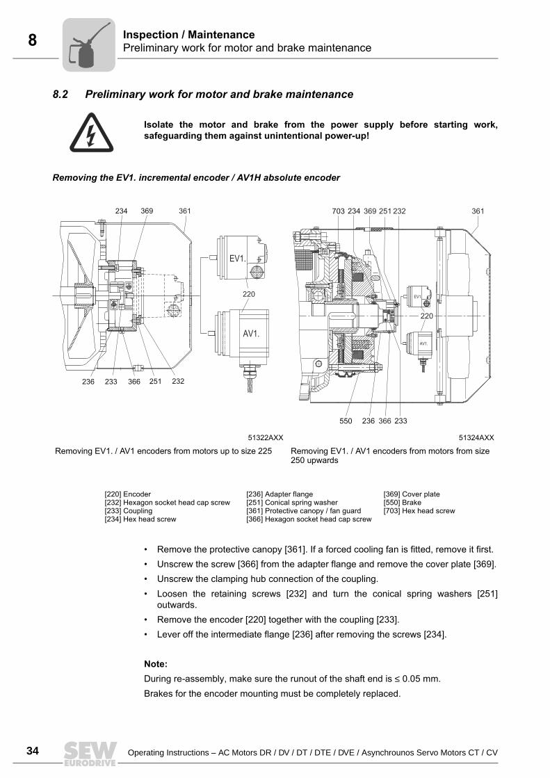
8.2 Preliminary work for motor and brake maintenance
Removing the EV1. incremental encoder / AV1H absolute encoder
Remove the protective canopy [361]. If a forced cooling fan is fitted, remove it first. Unscrew the screw [366] from the adapter flange and remove the cover plate [369]. Unscrew the clamping hub connection of the coupling. Loosen the retaining screws [232] and turn the conical spring washers [251]
outwards. Remove the encoder [220] together with the coupling [233]. Lever off the intermediate flange [236] after removing the screws [234].
Note:During re-assembly, make sure the runout of the shaft end is ≤ 0.05 mm.Brakes for the encoder mounting must be completely replaced.
Isolate the motor and brake from the power supply before starting work,safeguarding them against unintentional power-up!
51322AXX 51324AXX
Removing EV1. / AV1 encoders from motors up to size 225 Removing EV1. / AV1 encoders from motors from size 250 upwards
361
220
EV1.
AV1.
369
232251366233236
234 369 251 232 361234703
366236 233550
EV1.
AV1.
220
[220] Encoder[232] Hexagon socket head cap screw[233] Coupling[234] Hex head screw
[236] Adapter flange[251] Conical spring washer[361] Protective canopy / fan guard[366] Hexagon socket head cap screw
[369] Cover plate[550] Brake[703] Hex head screw
Operating Instructions – AC Motors DR / DV / DT / DTE / DVE / Asynchrounos Servo Motors CT / CV 35
8Preliminary work for motor and brake maintenanceInspection / Maintenance
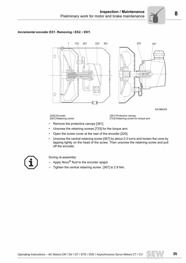
Incremental encoder ES1. Removing / ES2. / EH1.
Remove the protective canopy [361]. Unscrew the retaining screws [733] for the torque arm. Open the screw cover at the rear of the encoder [220]. Unscrew the central retaining screw [367] by about 2-3 turns and loosen the cone by
tapping lightly on the head of the screw. Then unscrew the retaining screw and pulloff the encoder.
54196AXX
[220] Encoder[367] Retaining screw
[361] Protective canopy[733] Retaining screw for torque arm
367733 220 3611 220 367
During re-assembly: Apply Noco® fluid to the encoder spigot Tighten the central retaining screw [367] to 2.9 Nm.
36 Operating Instructions – AC Motors DR / DV / DT / DTE / DVE / Asynchrounos Servo Motors CT / CV
8 Preliminary work for motor and brake maintenanceInspection / Maintenance
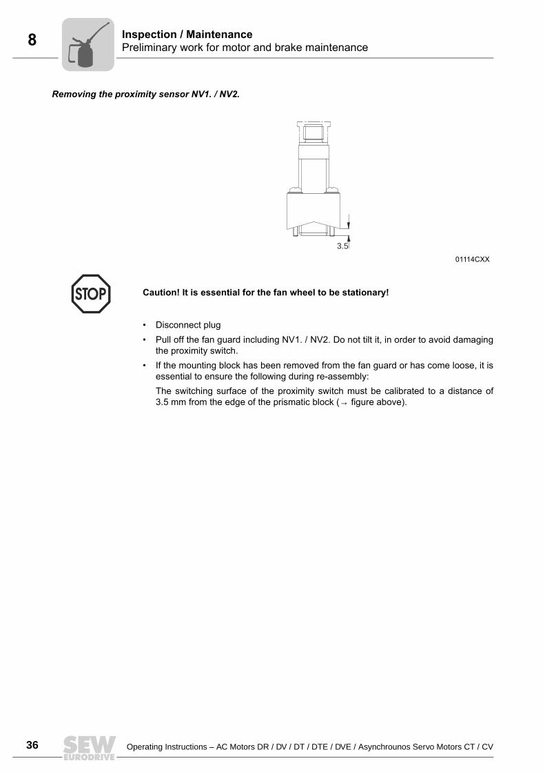
Removing the proximity sensor NV1. / NV2.
Disconnect plug Pull off the fan guard including NV1. / NV2. Do not tilt it, in order to avoid damaging
the proximity switch. If the mounting block has been removed from the fan guard or has come loose, it is
essential to ensure the following during re-assembly:The switching surface of the proximity switch must be calibrated to a distance of3.5 mm from the edge of the prismatic block (→ figure above).
01114CXX
Caution! It is essential for the fan wheel to be stationary!
3.5
Operating Instructions – AC Motors DR / DV / DT / DTE / DVE / Asynchrounos Servo Motors CT / CV 37
8Inspection / maintenance on the motorInspection / Maintenance
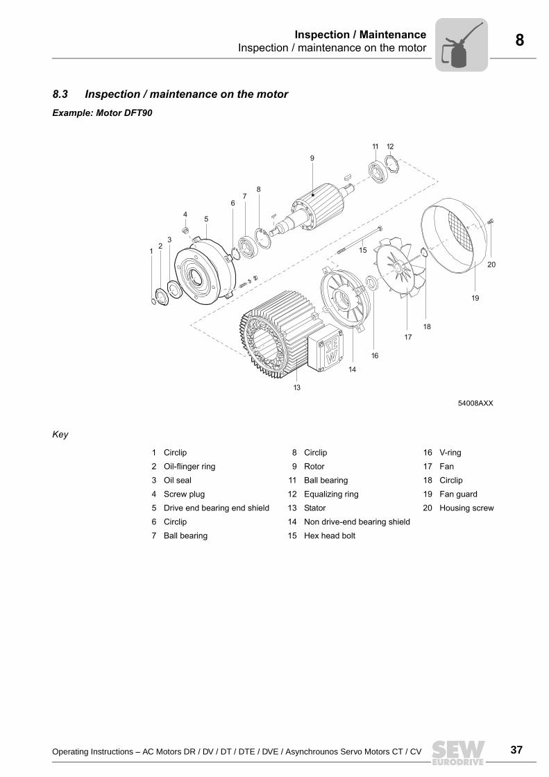
8.3 Inspection / maintenance on the motor Example: Motor DFT90
Key
54008AXX
12
3
45
67
8
9
11 12
13
14
16
1718
1
20
9
15
1 Circlip 8 Circlip 16 V-ring
2 Oil-flinger ring 9 Rotor 17 Fan
3 Oil seal 11 Ball bearing 18 Circlip
4 Screw plug 12 Equalizing ring 19 Fan guard
5 Drive end bearing end shield 13 Stator 20 Housing screw
6 Circlip 14 Non drive-end bearing shield
7 Ball bearing 15 Hex head bolt
38 Operating Instructions – AC Motors DR / DV / DT / DTE / DVE / Asynchrounos Servo Motors CT / CV
8 Inspection / maintenance on the motorInspection / Maintenance
Sequence
1. Remove the forced cooling fan and encoder, if installed (→ Sec. "Preliminary workfor motor and brake maintenance")
2. Remove flange or fan guard [19], fan [17].3. Remove the hex head bolt [15] from the drive end bearing end shield [5] and the non-
drive end bearing end shield [14], release the stator [13] from the drive end bearingend shield.
4. Motors with BM/BMG brake: Open the terminal box cover, unfasten the brake cable from the rectifier Push the non-drive end bearing end shield and the brake off the stator and
carefully lift them off (if necessary, run the brake cable along with trailing wire) Pull the stator back by approx. 3 to 4 cm
5. Motors with BMG02, BR03 brake: Remove the complete brake with the releasing lever (on version with manual
brake release)6. Visual inspection: Are there traces of gear oil or condensation inside the stator?
If not, continue with 9 If there is condensation, continue with 7 If there is gear oil, have the motor repaired by a specialist workshop
7. If there is moisture inside the stator: With gearmotors: Remove the motor from the gear unit With motors without a gear unit: Remove the drive end flange Remove the rotor [9]
8. Clean the winding, dry it and check it electrically (→ Sec. "Preliminary work")9. Replace the ball bearings [7], [11] (only use authorized ball bearings → Sec.
"Permitted ball bearing types")10.Reseal the stator seat ("Hylomar L Spezial") and grease the V-ring or labyrinth seal
(DR63)11.Install the motor, brake and accessories12.Check the gear unit (→ gear unit operating instructions)
Lubrication of the backstop
The backstop is supplied with Mobil LBZ low-viscosity grease as a lubricant andanticorrosion protection. If you want to use a different grease, make sure it complies withNLGI class 00/000, with a base oil viscosity of 42 mm2/s at 40 °C on a lithium saponifiedand mineral oil base. The temperature range extends from 50 °C to +90 °C. See thefollowing table for the amount of grease required.
Isolate the motor and brake from the supply, safeguarding them against uninten-tional power-up!
Motor type 71/80 90/100 112/132 132M/160M 160L/225 250/280
Grease [g] 9 15 15 20 45 80
Operating Instructions – AC Motors DR / DV / DT / DTE / DVE / Asynchrounos Servo Motors CT / CV 39
8Inspection / maintenance of the BMG02 brakeInspection / Maintenance
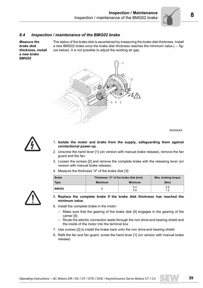
8.4 Inspection / maintenance of the BMG02 brakeMeasure the brake disk thickness, install a new brake BMG02
The status of the brake disk is ascertained by measuring the brake disk thickness. Installa new BMG02 brake once the brake disk thickness reaches the minimum value (→ fig-ure below). It is not possible to adjust the working air gap.
1. Isolate the motor and brake from the supply, safeguarding them againstunintentional power-up.
2. Unscrew the hand lever [1] (on version with manual brake release), remove the fanguard and the fan.
3. Loosen the screws [2] and remove the complete brake with the releasing lever (onversion with manual brake release).
4. Measure the thickness "d" of the brake disk [3]:
5. Replace the complete brake if the brake disk thickness has reached theminimum value.
6. Install the complete brake in the motor: Make sure that the gearing of the brake disk [4] engages in the gearing of the
carrier [5] Route the electric connection leads through the non drive-end bearing shield and
the inside of the motor into the terminal box7. Use screws [2] to install the brake back onto the non drive-end bearing shield8. Refit the fan and fan guard, screw the hand lever [1] (on version with manual brake
release)
50345AXX
Brake Thickness "d" of the brake disk [mm] Max. braking torque
Type Maximum Minimum [Nm]
BMG02 6 5.45.6
0.81.2
1
2
d
5 4 3
40 Operating Instructions – AC Motors DR / DV / DT / DTE / DVE / Asynchrounos Servo Motors CT / CV
8 Inspection / maintenance of the brake BR03Inspection / Maintenance
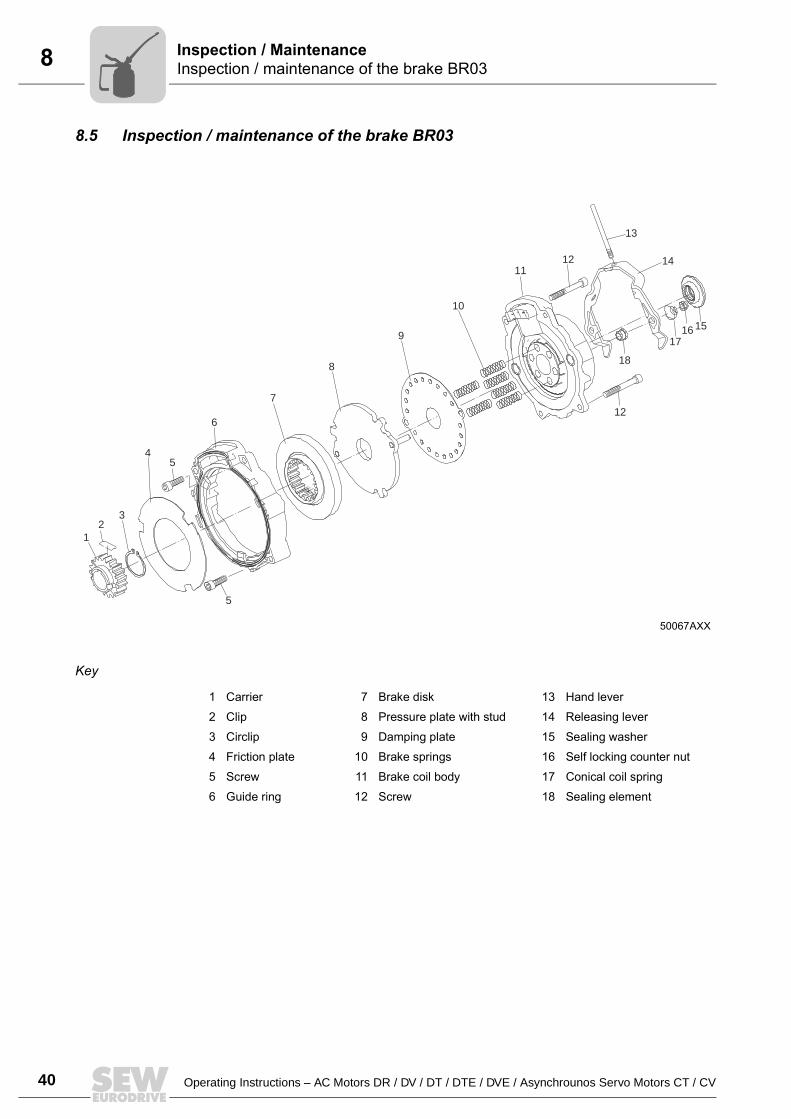
8.5 Inspection / maintenance of the brake BR03
Key
50067AXX
4
5
5
6
12
7
3
8
9
10
12 11
13
151617
18
12
14
1 Carrier 7 Brake disk 13 Hand lever
2 Clip 8 Pressure plate with stud 14 Releasing lever
3 Circlip 9 Damping plate 15 Sealing washer
4 Friction plate 10 Brake springs 16 Self locking counter nut
5 Screw 11 Brake coil body 17 Conical coil spring
6 Guide ring 12 Screw 18 Sealing element
Operating Instructions – AC Motors DR / DV / DT / DTE / DVE / Asynchrounos Servo Motors CT / CV 41
8Inspection / maintenance of the brake BR03Inspection / Maintenance
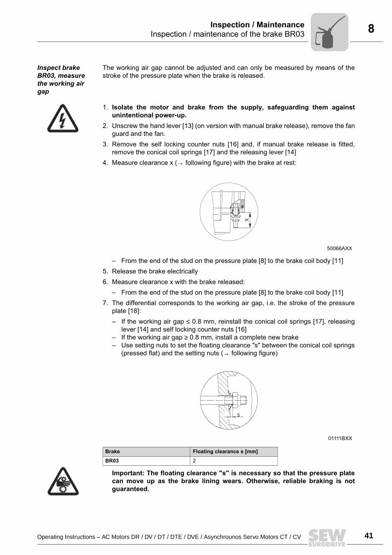
Inspect brake BR03, measure the working air gap
The working air gap cannot be adjusted and can only be measured by means of thestroke of the pressure plate when the brake is released.
1. Isolate the motor and brake from the supply, safeguarding them againstunintentional power-up.
2. Unscrew the hand lever [13] (on version with manual brake release), remove the fanguard and the fan.
3. Remove the self locking counter nuts [16] and, if manual brake release is fitted,remove the conical coil springs [17] and the releasing lever [14]
4. Measure clearance x (→ following figure) with the brake at rest:
From the end of the stud on the pressure plate [8] to the brake coil body [11]5. Release the brake electrically6. Measure clearance x with the brake released:
From the end of the stud on the pressure plate [8] to the brake coil body [11]7. The differential corresponds to the working air gap, i.e. the stroke of the pressure
plate [18]: If the working air gap ≤ 0.8 mm, reinstall the conical coil springs [17], releasing
lever [14] and self locking counter nuts [16] If the working air gap ≥ 0.8 mm, install a complete new brake Use setting nuts to set the floating clearance "s" between the conical coil springs
(pressed flat) and the setting nuts (→ following figure)
Important: The floating clearance "s" is necessary so that the pressure platecan move up as the brake lining wears. Otherwise, reliable braking is notguaranteed.
50066AXX
01111BXX
Brake Floating clearance s [mm]
BR03 2
X
s
42 Operating Instructions – AC Motors DR / DV / DT / DTE / DVE / Asynchrounos Servo Motors CT / CV
8 Inspection / maintenance of the brake BR03Inspection / Maintenance
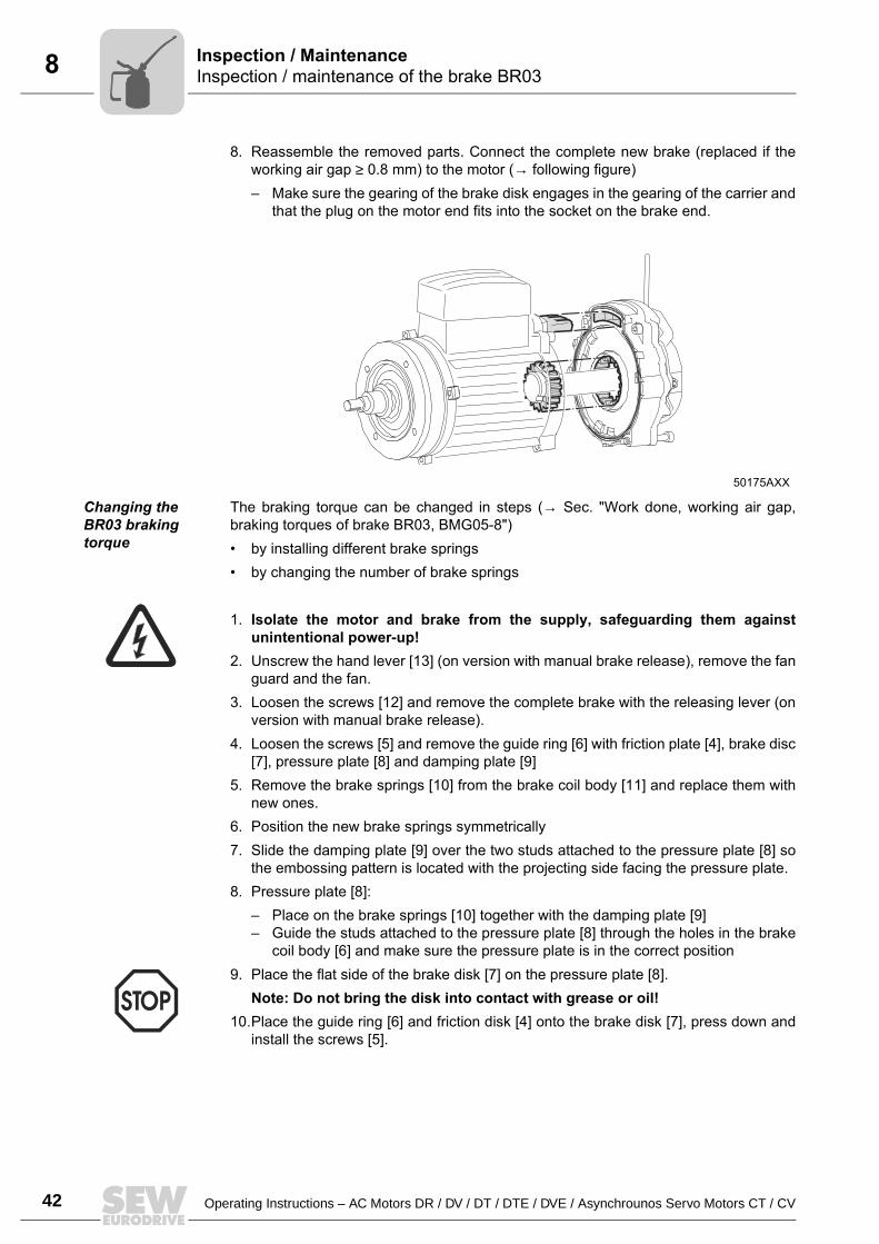
8. Reassemble the removed parts. Connect the complete new brake (replaced if theworking air gap ≥ 0.8 mm) to the motor (→ following figure) Make sure the gearing of the brake disk engages in the gearing of the carrier and
that the plug on the motor end fits into the socket on the brake end.
Changing the BR03 braking torque
The braking torque can be changed in steps (→ Sec. "Work done, working air gap,braking torques of brake BR03, BMG05-8") by installing different brake springs by changing the number of brake springs
1. Isolate the motor and brake from the supply, safeguarding them againstunintentional power-up!
2. Unscrew the hand lever [13] (on version with manual brake release), remove the fanguard and the fan.
3. Loosen the screws [12] and remove the complete brake with the releasing lever (onversion with manual brake release).
4. Loosen the screws [5] and remove the guide ring [6] with friction plate [4], brake disc[7], pressure plate [8] and damping plate [9]
5. Remove the brake springs [10] from the brake coil body [11] and replace them withnew ones.
6. Position the new brake springs symmetrically7. Slide the damping plate [9] over the two studs attached to the pressure plate [8] so
the embossing pattern is located with the projecting side facing the pressure plate.8. Pressure plate [8]:
Place on the brake springs [10] together with the damping plate [9] Guide the studs attached to the pressure plate [8] through the holes in the brake
coil body [6] and make sure the pressure plate is in the correct position9. Place the flat side of the brake disk [7] on the pressure plate [8].
Note: Do not bring the disk into contact with grease or oil!10.Place the guide ring [6] and friction disk [4] onto the brake disk [7], press down and
install the screws [5].
50175AXX
Operating Instructions – AC Motors DR / DV / DT / DTE / DVE / Asynchrounos Servo Motors CT / CV 43
8Inspection / maintenance of the brake BR03Inspection / Maintenance
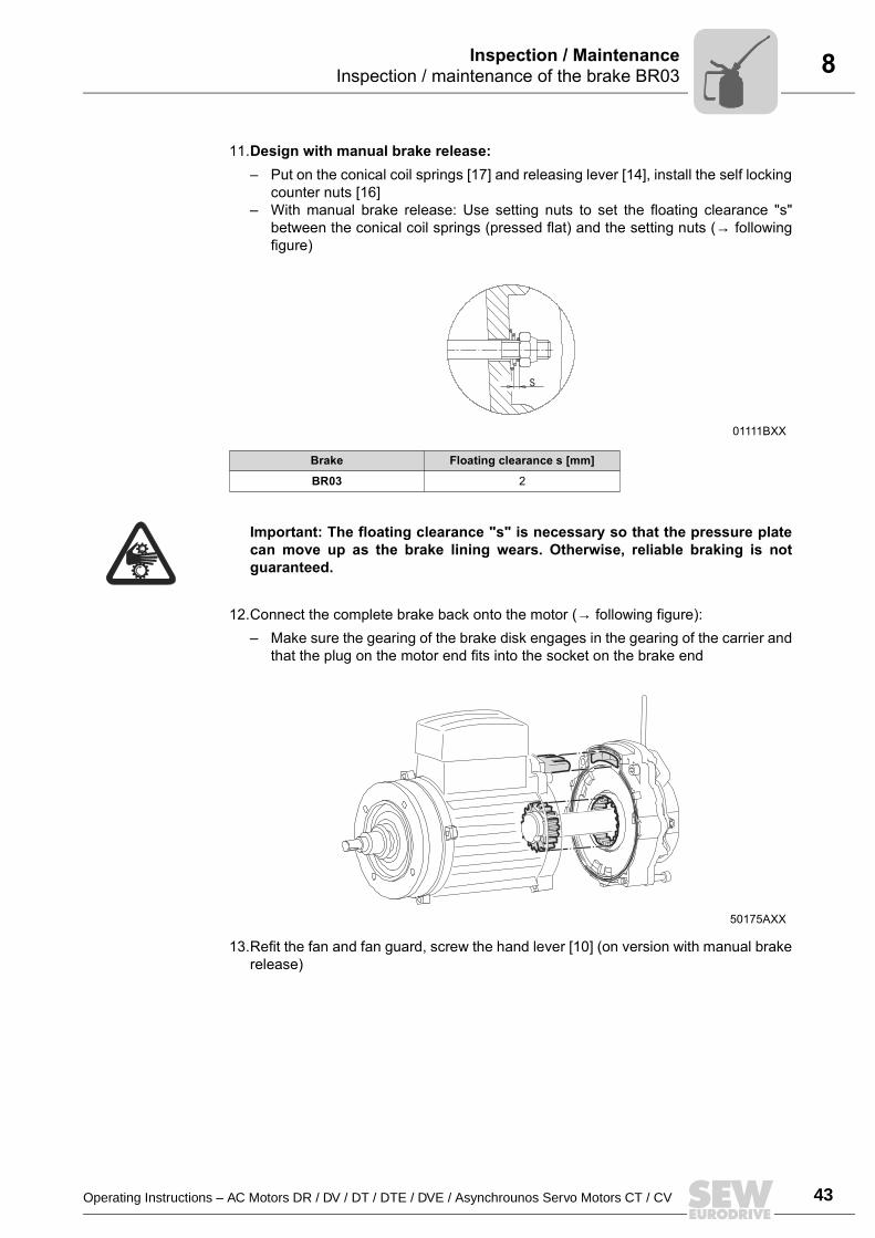
11.Design with manual brake release: Put on the conical coil springs [17] and releasing lever [14], install the self locking
counter nuts [16] With manual brake release: Use setting nuts to set the floating clearance "s"
between the conical coil springs (pressed flat) and the setting nuts (→ followingfigure)
Important: The floating clearance "s" is necessary so that the pressure platecan move up as the brake lining wears. Otherwise, reliable braking is notguaranteed.
12.Connect the complete brake back onto the motor (→ following figure): Make sure the gearing of the brake disk engages in the gearing of the carrier and
that the plug on the motor end fits into the socket on the brake end
13.Refit the fan and fan guard, screw the hand lever [10] (on version with manual brakerelease)
01111BXX
Brake Floating clearance s [mm]
BR03 2
50175AXX
s
44 Operating Instructions – AC Motors DR / DV / DT / DTE / DVE / Asynchrounos Servo Motors CT / CV
8 Inspection / maintenance for BMG05-8, BM15-62 brakesInspection / Maintenance
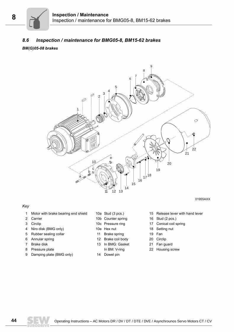
8.6 Inspection / maintenance for BMG05-8, BM15-62 brakesBM(G)05-08 brakes
Key
01955AXX
1
23
45
67
89
10
ab
c
11 12 1314
1516
1718
19
20
2122
e
1 Motor with brake bearing end shield 10a Stud (3 pcs.) 15 Release lever with hand lever2 Carrier 10b Counter spring 16 Stud (2 pcs.)3 Circlip 10c Pressure ring 17 Conical coil spring4 Niro disk (BMG only) 10e Hex nut 18 Setting nut5 Rubber sealing collar 11 Brake spring 19 Fan6 Annular spring 12 Brake coil body 20 Circlip7 Brake disk 13 In BMG: Gasket 21 Fan guard8 Pressure plate In BM: V-ring 22 Housing screw9 Damping plate (BMG only) 14 Dowel pin
Operating Instructions – AC Motors DR / DV / DT / DTE / DVE / Asynchrounos Servo Motors CT / CV 45
8Inspection / maintenance for BMG05-8, BM15-62 brakesInspection / Maintenance
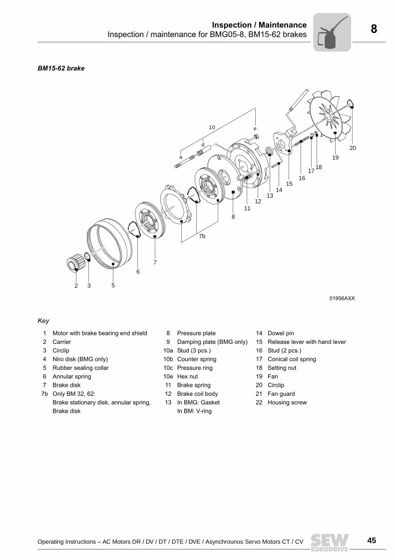
BM15-62 brake
Key
01956AXX
2 3 5
6
7
7b
18
112
1314
1516
1718
19
20
10
a
d
e
1 Motor with brake bearing end shield 8 Pressure plate 14 Dowel pin2 Carrier 9 Damping plate (BMG only) 15 Release lever with hand lever3 Circlip 10a Stud (3 pcs.) 16 Stud (2 pcs.)4 Niro disk (BMG only) 10b Counter spring 17 Conical coil spring5 Rubber sealing collar 10c Pressure ring 18 Setting nut6 Annular spring 10e Hex nut 19 Fan7 Brake disk 11 Brake spring 20 Circlip
7b Only BM 32, 62: 12 Brake coil body 21 Fan guardBrake stationary disk, annular spring, 13 In BMG: Gasket 22 Housing screwBrake disk In BM: V-ring
46 Operating Instructions – AC Motors DR / DV / DT / DTE / DVE / Asynchrounos Servo Motors CT / CV
8 Inspection / maintenance for BMG05-8, BM15-62 brakesInspection / Maintenance
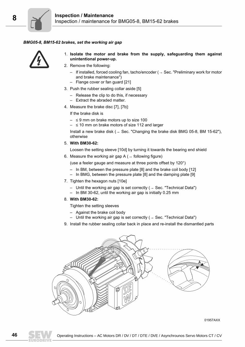
BMG05-8, BM15-62 brakes, set the working air gap
1. Isolate the motor and brake from the supply, safeguarding them againstunintentional power-up.
2. Remove the following: If installed, forced cooling fan, tacho/encoder (→ Sec. "Preliminary work for motor
and brake maintenance") Flange cover or fan guard [21]
3. Push the rubber sealing collar aside [5] Release the clip to do this, if necessary Extract the abraded matter.
4. Measure the brake disc [7], [7b]:If the brake disk is ≤ 9 mm on brake motors up to size 100 ≤ 10 mm on brake motors of size 112 and largerInstall a new brake disk (→ Sec. "Changing the brake disk BMG 05-8, BM 15-62"),otherwise
5. With BM30-62:Loosen the setting sleeve [10d] by turning it towards the bearing end shield
6. Measure the working air gap A (→ following figure)(use a feeler gauge and measure at three points offset by 120°) In BM, between the pressure plate [8] and the brake coil body [12] In BMG, between the pressure plate [8] and the damping plate [9]
7. Tighten the hexagon nuts [10e] Until the working air gap is set correctly (→ Sec. "Technical Data") In BM 30-62, until the working air gap is initially 0.25 mm
8. With BM30-62:Tighten the setting sleeves Against the brake coil body Until the working air gap is set correctly (→ Sec. "Technical Data")
9. Install the rubber sealing collar back in place and re-install the dismantled parts
01957AXX
A
.
Operating Instructions – AC Motors DR / DV / DT / DTE / DVE / Asynchrounos Servo Motors CT / CV 47
8Inspection / maintenance for BMG05-8, BM15-62 brakesInspection / Maintenance
Changing the BMG05-8, BM15-62 brake discsWhen fitting a new brake disk (in BMG05-4 ≤ 9 mm; in BMG62 ≤ 10 mm) inspect theother removed parts as well and install new ones if necessary.
1. Isolate the motor and brake from the supply, safeguarding them againstunintentional power-up!
2. Remove the following: If installed, forced cooling fan, tacho/encoder (→ Sec. "Preliminary work for motor
and brake maintenance") Flange or fan guard [21], circlip [20] and fan [19].
3. Remove the rubber sealing collar [5] and the manual brake release: Setting nuts [18], conical coil springs [17], studs [16], release lever [15], dowel pin
[14]4. Unscrew hexagon nuts [10e], carefully pull off the coil body [12] (brake cable!) and
take out the brake springs [11].5. Remove the damping cable [9], pressure plate [8] and brake disc [7], [7b], clean the
brake components6. Install a new brake disk7. Re-install the brake components
Except for the rubber sealing collar, fan and fan guard, set the working air gap (→Sec. "Inspecting brake BMG 05-8, BM 30-62, setting the working air gap", points5 to 8)
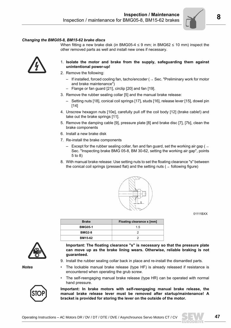
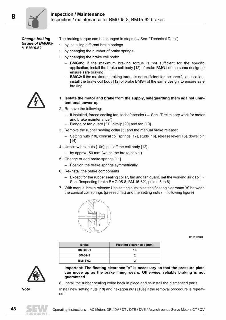
8. With manual brake release: Use setting nuts to set the floating clearance "s" betweenthe conical coil springs (pressed flat) and the setting nuts (→ following figure)
Important: The floating clearance "s" is necessary so that the pressure platecan move up as the brake lining wears. Otherwise, reliable braking is notguaranteed.
9. Install the rubber sealing collar back in place and re-install the dismantled parts.Notes The lockable manual brake release (type HF) is already released if resistance is
encountered when operating the grub screw. The self-reengaging manual brake release (type HR) can be operated with normal
hand pressure.Important: In brake motors with self-reengaging manual brake release, themanual brake release lever must be removed after startup/maintenance! Abracket is provided for storing the lever on the outside of the motor.
01111BXX
Brake Floating clearance s [mm]
BMG05-1 1.5
BMG2-8 2
BM15-62 2
s
48 Operating Instructions – AC Motors DR / DV / DT / DTE / DVE / Asynchrounos Servo Motors CT / CV
8 Inspection / maintenance for BMG05-8, BM15-62 brakesInspection / Maintenance
Change braking torque of BMG05-8, BM15-62
The braking torque can be changed in steps (→ Sec. "Technical Data") by installing different brake springs by changing the number of brake springs by changing the brake coil body:
BMG05: if the maximum braking torque is not sufficient for the specificapplication, install the brake coil body [12] of brake BMG1 of the same design toensure safe braking
BMG2: if the maximum braking torque is not sufficient for the specific application,install the brake coil body [12] of brake BMG4 of the same design to ensure safebraking
1. Isolate the motor and brake from the supply, safeguarding them against unin-tentional power-up
2. Remove the following: If installed, forced cooling fan, tacho/encoder (→ Sec. "Preliminary work for motor
and brake maintenance") Flange or fan guard [21], circlip [20] and fan [19].
3. Remove the rubber sealing collar [5] and the manual brake release: Setting nuts [18], conical coil springs [17], studs [16], release lever [15], dowel pin
[14]4. Unscrew hex nuts [10e], pull off the coil body [12].
by approx. 50 mm (watch the brake cable!)5. Change or add brake springs [11]
Position the brake springs symmetrically6. Re-install the brake components
Except for the rubber sealing collar, fan and fan guard, set the working air gap (→Sec. "Inspecting brake BMG 05-8, BM 15-62", points 5 to 8)
7. With manual brake release: Use setting nuts to set the floating clearance "s" betweenthe conical coil springs (pressed flat) and the setting nuts (→ following figure)
Important: The floating clearance "s" is necessary so that the pressure platecan move up as the brake lining wears. Otherwise, reliable braking is notguaranteed.
8. Install the rubber sealing collar back in place and re-install the dismantled parts.Note Install new setting nuts [18] and hexagon nuts [10e] if the removal procedure is repeat-
ed!
01111BXX
Brake Floating clearance s [mm]
BMG05-1 1.5
BMG2-8 2
BM15-62 2
s
Operating Instructions – AC Motors DR / DV / DT / DTE / DVE / Asynchrounos Servo Motors CT / CV 49
8Inspection / maintenance of the BMG61/122 brakeInspection / Maintenance
8.7 Inspection / maintenance of the BMG61/122 brake
BMG61/122 brakes
Key
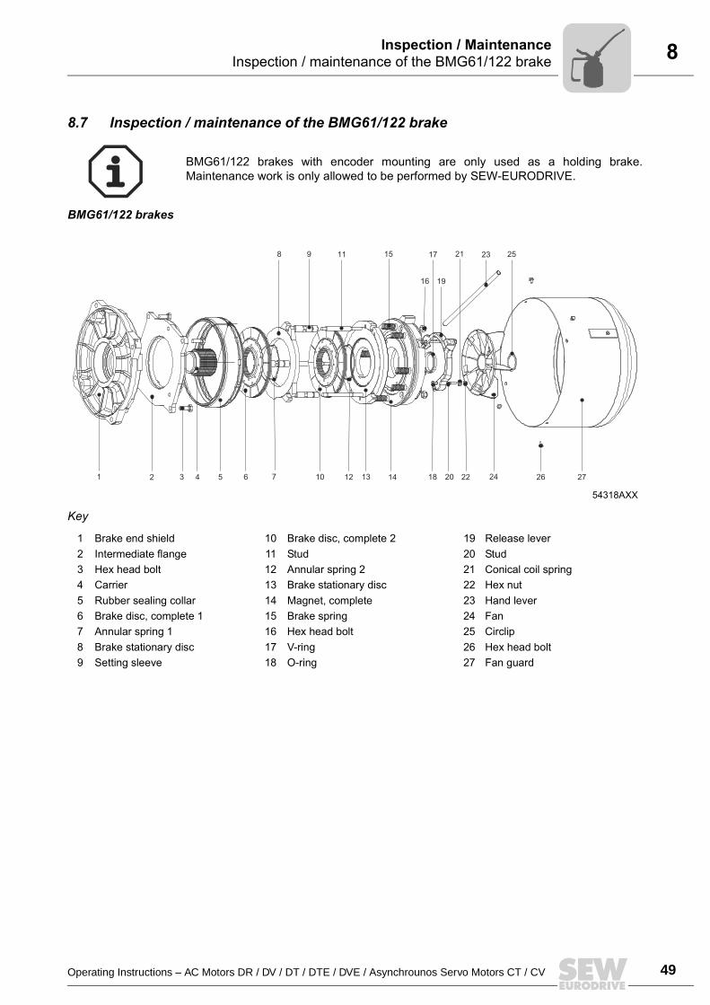
BMG61/122 brakes with encoder mounting are only used as a holding brake.Maintenance work is only allowed to be performed by SEW-EURODRIVE.
54318AXX
1 2
9 11
64
8
753 10 12 13
16
14 18
19
17
22 26 27
21
24
2523
20
15
1 Brake end shield 10 Brake disc, complete 2 19 Release lever2 Intermediate flange 11 Stud 20 Stud3 Hex head bolt 12 Annular spring 2 21 Conical coil spring4 Carrier 13 Brake stationary disc 22 Hex nut5 Rubber sealing collar 14 Magnet, complete 23 Hand lever6 Brake disc, complete 1 15 Brake spring 24 Fan7 Annular spring 1 16 Hex head bolt 25 Circlip8 Brake stationary disc 17 V-ring 26 Hex head bolt9 Setting sleeve 18 O-ring 27 Fan guard
50 Operating Instructions – AC Motors DR / DV / DT / DTE / DVE / Asynchrounos Servo Motors CT / CV
8 Inspection / maintenance of the BMG61/122 brakeInspection / Maintenance
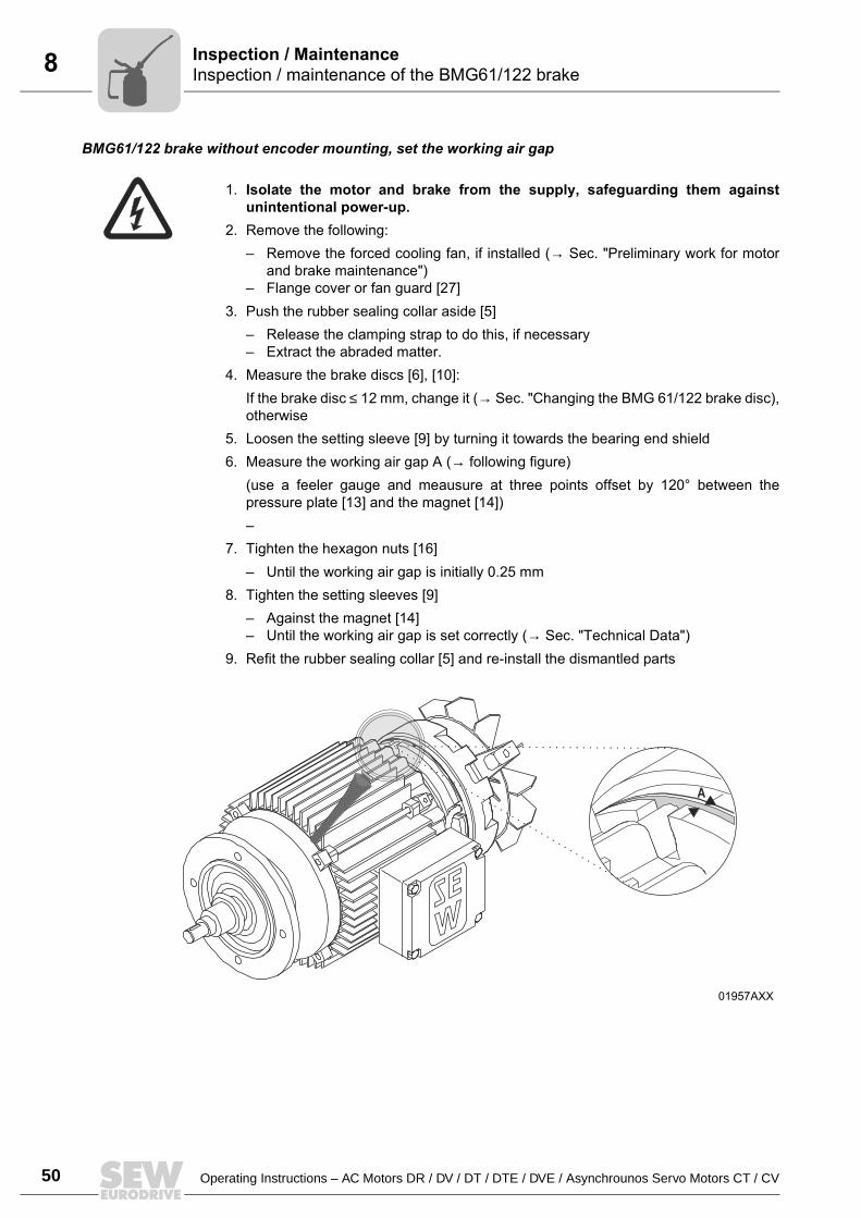
BMG61/122 brake without encoder mounting, set the working air gap
1. Isolate the motor and brake from the supply, safeguarding them againstunintentional power-up.
2. Remove the following: Remove the forced cooling fan, if installed (→ Sec. "Preliminary work for motor
and brake maintenance") Flange cover or fan guard [27]
3. Push the rubber sealing collar aside [5] Release the clamping strap to do this, if necessary Extract the abraded matter.
4. Measure the brake discs [6], [10]:If the brake disc ≤ 12 mm, change it (→ Sec. "Changing the BMG 61/122 brake disc),otherwise
5. Loosen the setting sleeve [9] by turning it towards the bearing end shield6. Measure the working air gap A (→ following figure)
(use a feeler gauge and meausure at three points offset by 120° between thepressure plate [13] and the magnet [14])
7. Tighten the hexagon nuts [16] Until the working air gap is initially 0.25 mm
8. Tighten the setting sleeves [9] Against the magnet [14] Until the working air gap is set correctly (→ Sec. "Technical Data")
9. Refit the rubber sealing collar [5] and re-install the dismantled parts
01957AXX
A
.
Operating Instructions – AC Motors DR / DV / DT / DTE / DVE / Asynchrounos Servo Motors CT / CV 51
8Inspection / maintenance of the BMG61/122 brakeInspection / Maintenance
BMG 61/122 brake without encoder mounting, change the brake discWhen fitting a new brake disk (≤ 12 mm), inspect the other removed parts as well andinstall new ones if necessary.
1. Isolate the motor and brake from the supply, safeguarding them againstunintentional power-up!
2. Remove the following: Forced cooling fan, if installed (→ Sec. "Preliminary work for motor and brake
maintenance") Flange or fan guard [27], circlip [25] and fan [24].
3. Remove the rubber sealing collar [5] and the manual brake release: Hex nuts [16], conical coil springs [21], studs [20], release level [17]
4. Loosen the hex nuts [16], remove the connection cable to the plug connector for themagnet [14], remove the magnet, and remove the brake springs [15].
5. Remove the complete pressure plate [8], the complete brake disc [10] as well as thebrake stationary disk and complete brake disc [6] for BMG122, clean the brakecomponents.
6. Install a new brake disk7. Re-install the brake components
Except for the rubber sealing collar, fan and fan guard, set the working air gap (→Sec. "Inspecting brake BMG 61/122, setting the working air gap", points 5 to 8)
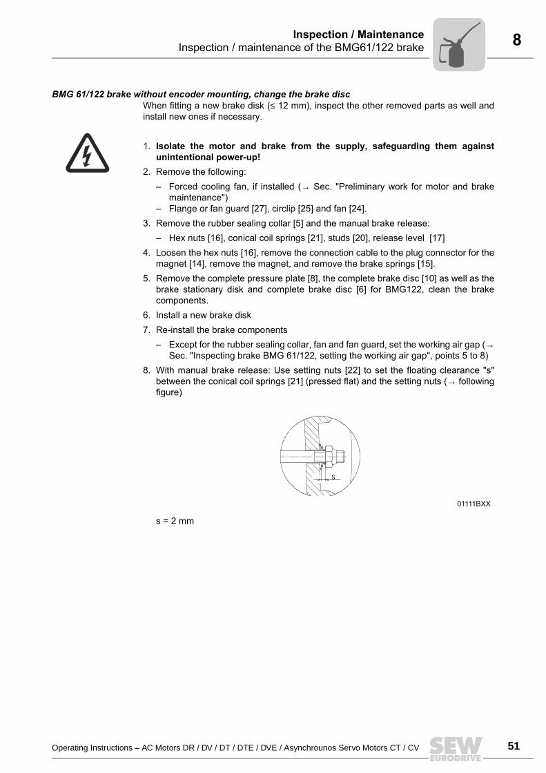
8. With manual brake release: Use setting nuts [22] to set the floating clearance "s"between the conical coil springs [21] (pressed flat) and the setting nuts (→ followingfigure)
s = 2 mm
01111BXX
s
52 Operating Instructions – AC Motors DR / DV / DT / DTE / DVE / Asynchrounos Servo Motors CT / CV
9 Work done, braking torque BMG02Technical Data
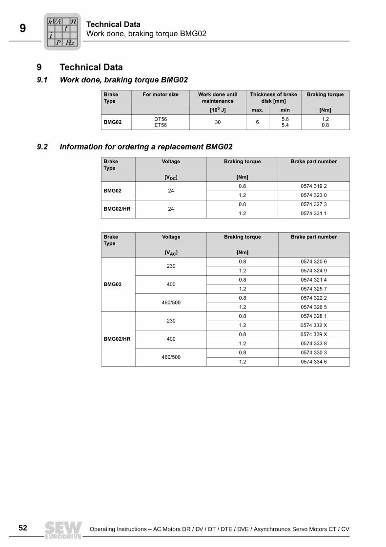
9 Technical Data9.1 Work done, braking torque BMG02
9.2 Information for ordering a replacement BMG02
BrakeType
For motor size Work done until maintenance
Thickness of brake disk [mm]
Braking torque
[106 J] max. min [Nm]
BMG02 DT56ET56 30 6 5.6
5.41.20.8
BrakeType
Voltage Braking torque Brake part number
[VDC] [Nm]
BMG02 240.8 0574 319 2
1.2 0574 323 0
BMG02/HR 240.8 0574 327 3
1.2 0574 331 1
BrakeType
Voltage Braking torque Brake part number
[VAC] [Nm]
BMG02
2300.8 0574 320 6
1.2 0574 324 9
4000.8 0574 321 4
1.2 0574 325 7
460/5000.8 0574 322 2
1.2 0574 326 5
BMG02/HR
2300.8 0574 328 1
1.2 0574 332 X
4000.8 0574 329 X
1.2 0574 333 8
460/5000.8 0574 330 3
1.2 0574 334 6
Pi
fkVA
Hz
n
Operating Instructions – AC Motors DR / DV / DT / DTE / DVE / Asynchrounos Servo Motors CT / CV 53
9Work done, working air gap, braking torques of BMG05-8, BR03, BC, BdTechnical Data
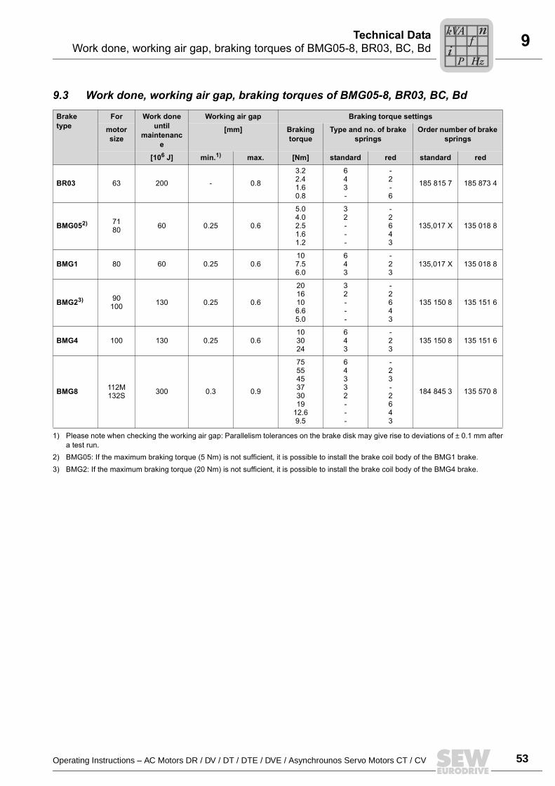
9.3 Work done, working air gap, braking torques of BMG05-8, BR03, BC, Bd
Brake type
For Work done until
maintenance
Working air gap Braking torque settings
motor size
[mm] Braking torque
Type and no. of brake springs
Order number of brake springs
[106 J] min.1)
1) Please note when checking the working air gap: Parallelism tolerances on the brake disk may give rise to deviations of ± 0.1 mm aftera test run.
max. [Nm] standard red standard red
BR03 63 200 - 0.8
3.22.41.60.8
643-
-2-6
185 815 7 185 873 4
BMG052)
2) BMG05: If the maximum braking torque (5 Nm) is not sufficient, it is possible to install the brake coil body of the BMG1 brake.
7180 60 0.25 0.6
5.04.02.51.61.2
32---
-2643
135,017 X 135 018 8
BMG1 80 60 0.25 0.6107.56.0
643
-23
135,017 X 135 018 8
BMG23)
3) BMG2: If the maximum braking torque (20 Nm) is not sufficient, it is possible to install the brake coil body of the BMG4 brake.
90100 130 0.25 0.6
2016106.65.0
32---
-2643
135 150 8 135 151 6
BMG4 100 130 0.25 0.6103024
643
-23
135 150 8 135 151 6
BMG8 112M132S 300 0.3 0.9
755545373019
12.69.5
64332---
-23-2643
184 845 3 135 570 8
Pi
fkVA
Hz
n
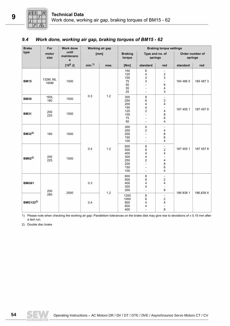
54 Operating Instructions – AC Motors DR / DV / DT / DTE / DVE / Asynchrounos Servo Motors CT / CV
9 Work done, working air gap, braking torques of BM15 - 62Technical Data
9.4 Work done, working air gap, braking torques of BM15 - 62
Brake type
For Work done until
maintenance
Working air gap Braking torque settings
motor size
[mm] Braking torque
Type and no. of springs
Order number of springs
[106 J] min.1)
1) Please note when checking the working air gap: Parallelism tolerances on the brake disk may give rise to deviations of ± 0.15 mm aftera test run.
max. [Nm] standard red standard red
BM15 132M, ML160M 1000
0.3 1.2
15012510075503525
6433---
-23-643
184 486 5 184 487 3
BM30 160L180 1500 300
2502001501251007550
86442---
-24-4864
187 455 1 187 457 8BM31 200
225 1500
BM322)
2) Double disc brake
180 1500
0.4 1.2
300250200150100
42---
-4864
187 455 1 187 457 8
BM622) 200225 1500
600500400300250200150100
86442---
-24-4864
BMG61
250280 2500
0.3
1.2
600500400300200
8644-
-24-8
186 838 1 186,839 X
BMG1222) 0.4
12001000800600400
8644-
-24-8
Pi
fkVA
Hz
n
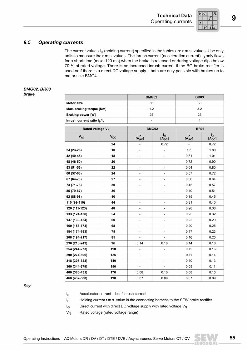
Operating Instructions – AC Motors DR / DV / DT / DTE / DVE / Asynchrounos Servo Motors CT / CV 55
9Operating currentsTechnical Data
9.5 Operating currentsThe current values IH (holding current) specified in the tables are r.m.s. values. Use onlyunits to measure the r.m.s. values. The inrush current (acceleration current) IB only flowsfor a short time (max. 120 ms) when the brake is released or during voltage dips below70 % of rated voltage. There is no increased inrush current if the BG brake rectifier isused or if there is a direct DC voltage supply both are only possible with brakes up tomotor size BMG4.
BMG02, BR03 brake
Key
BMG02 BR03
Motor size 56 63
Max. braking torque [Nm] 1.2 3.2
Braking power [W] 25 25
Inrush current ratio IB/IH - 4
Rated voltage VN BMG02 BR03
IH[AAC]
IG[ADC]
IH[AAC]
IG[ADC]VAC VDC
24 - 0.72 - 0.72
24 (23-26) 10 - - 1.5 1.80
42 (40-45) 18 - - 0.81 1.01
48 (46-50) 20 - - 0.72 0.90
53 (51-56) 22 - - 0.64 0.80
60 (57-63) 24 - - 0.57 0.72
67 (64-70) 27 - - 0.50 0.64
73 (71-78) 30 - - 0.45 0.57
85 (79-87) 36 - - 0.40 0.51
92 (88-98) 40 - - 0.35 0.45
110 (99-110) 44 - - 0.31 0.40
120 (111-123) 48 - - 0.28 0.36
133 (124-138) 54 - - 0.25 0.32
147 (139-154) 60 - - 0.22 0.29
160 (155-173) 68 - - 0.20 0.25
184 (174-193) 75 - - 0.17 0.23
208 (194-217) 85 - - 0.16 0.20
230 (218-243) 96 0.14 0.18 0.14 0.18
254 (244-273) 110 - - 0.12 0.16
290 (274-306) 125 - - 0.11 0.14
318 (307-343) 140 - - 0.10 0.13
360 (344-379) 150 - - 0.09 0.11
400 (380-431) 170 0.08 0.10 0.08 0.10
460 (432-500) 190 0.07 0.09 0.07 0.09
IB Accelerator current brief inrush current
IH Holding current r.m.s. value in the connecting harness to the SEW brake rectifier
IG Direct current with direct DC voltage supply with rated voltage VN
VN Rated voltage (rated voltage range)
Pi
fkVA
Hz
n
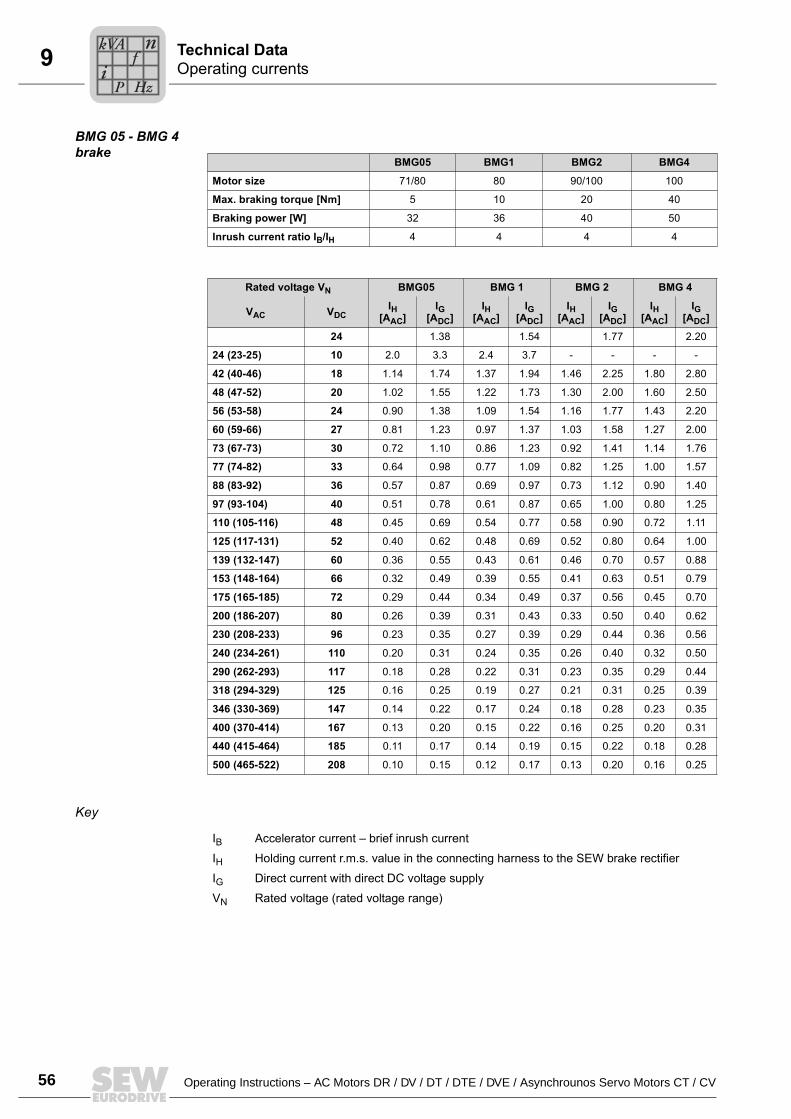
56 Operating Instructions – AC Motors DR / DV / DT / DTE / DVE / Asynchrounos Servo Motors CT / CV
9 Operating currentsTechnical Data
BMG 05 - BMG 4 brake
Key
BMG05 BMG1 BMG2 BMG4
Motor size 71/80 80 90/100 100
Max. braking torque [Nm] 5 10 20 40
Braking power [W] 32 36 40 50
Inrush current ratio IB/IH 4 4 4 4
Rated voltage VN BMG05 BMG 1 BMG 2 BMG 4
IH[AAC]
IG[ADC]
IH[AAC]
IG[ADC]
IH[AAC]
IG[ADC]
IH[AAC]
IG[ADC]VAC VDC
24 1.38 1.54 1.77 2.20
24 (23-25) 10 2.0 3.3 2.4 3.7 - - - -
42 (40-46) 18 1.14 1.74 1.37 1.94 1.46 2.25 1.80 2.80
48 (47-52) 20 1.02 1.55 1.22 1.73 1.30 2.00 1.60 2.50
56 (53-58) 24 0.90 1.38 1.09 1.54 1.16 1.77 1.43 2.20
60 (59-66) 27 0.81 1.23 0.97 1.37 1.03 1.58 1.27 2.00
73 (67-73) 30 0.72 1.10 0.86 1.23 0.92 1.41 1.14 1.76
77 (74-82) 33 0.64 0.98 0.77 1.09 0.82 1.25 1.00 1.57
88 (83-92) 36 0.57 0.87 0.69 0.97 0.73 1.12 0.90 1.40
97 (93-104) 40 0.51 0.78 0.61 0.87 0.65 1.00 0.80 1.25
110 (105-116) 48 0.45 0.69 0.54 0.77 0.58 0.90 0.72 1.11
125 (117-131) 52 0.40 0.62 0.48 0.69 0.52 0.80 0.64 1.00
139 (132-147) 60 0.36 0.55 0.43 0.61 0.46 0.70 0.57 0.88
153 (148-164) 66 0.32 0.49 0.39 0.55 0.41 0.63 0.51 0.79
175 (165-185) 72 0.29 0.44 0.34 0.49 0.37 0.56 0.45 0.70
200 (186-207) 80 0.26 0.39 0.31 0.43 0.33 0.50 0.40 0.62
230 (208-233) 96 0.23 0.35 0.27 0.39 0.29 0.44 0.36 0.56
240 (234-261) 110 0.20 0.31 0.24 0.35 0.26 0.40 0.32 0.50
290 (262-293) 117 0.18 0.28 0.22 0.31 0.23 0.35 0.29 0.44
318 (294-329) 125 0.16 0.25 0.19 0.27 0.21 0.31 0.25 0.39
346 (330-369) 147 0.14 0.22 0.17 0.24 0.18 0.28 0.23 0.35
400 (370-414) 167 0.13 0.20 0.15 0.22 0.16 0.25 0.20 0.31
440 (415-464) 185 0.11 0.17 0.14 0.19 0.15 0.22 0.18 0.28
500 (465-522) 208 0.10 0.15 0.12 0.17 0.13 0.20 0.16 0.25
IB Accelerator current brief inrush current
IH Holding current r.m.s. value in the connecting harness to the SEW brake rectifier
IG Direct current with direct DC voltage supply
VN Rated voltage (rated voltage range)
Pi
fkVA
Hz
n
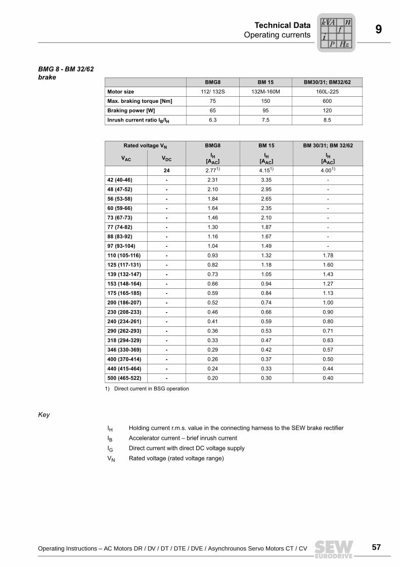
Operating Instructions – AC Motors DR / DV / DT / DTE / DVE / Asynchrounos Servo Motors CT / CV 57
9Operating currentsTechnical Data
BMG 8 - BM 32/62 brake
Key
BMG8 BM 15 BM30/31; BM32/62
Motor size 112/ 132S 132M-160M 160L-225
Max. braking torque [Nm] 75 150 600
Braking power [W] 65 95 120
Inrush current ratio IB/IH 6.3 7.5 8.5
Rated voltage VN BMG8 BM 15 BM 30/31; BM 32/62
IH[AAC]
IH[AAC]
IH[AAC]VAC VDC
24 2.771)
1) Direct current in BSG operation
4.151) 4.001)
42 (40-46) - 2.31 3.35 -
48 (47-52) - 2.10 2.95 -
56 (53-58) - 1.84 2.65 -
60 (59-66) - 1.64 2.35 -
73 (67-73) - 1.46 2.10 -
77 (74-82) - 1.30 1.87 -
88 (83-92) - 1.16 1.67 -
97 (93-104) - 1.04 1.49 -
110 (105-116) - 0.93 1.32 1.78
125 (117-131) - 0.82 1.18 1.60
139 (132-147) - 0.73 1.05 1.43
153 (148-164) - 0.66 0.94 1.27
175 (165-185) - 0.59 0.84 1.13
200 (186-207) - 0.52 0.74 1.00
230 (208-233) - 0.46 0.66 0.90
240 (234-261) - 0.41 0.59 0.80
290 (262-293) - 0.36 0.53 0.71
318 (294-329) - 0.33 0.47 0.63
346 (330-369) - 0.29 0.42 0.57
400 (370-414) - 0.26 0.37 0.50
440 (415-464) - 0.24 0.33 0.44
500 (465-522) - 0.20 0.30 0.40
IH Holding current r.m.s. value in the connecting harness to the SEW brake rectifier
IB Accelerator current brief inrush current
IG Direct current with direct DC voltage supply
VN Rated voltage (rated voltage range)
Pi
fkVA
Hz
n
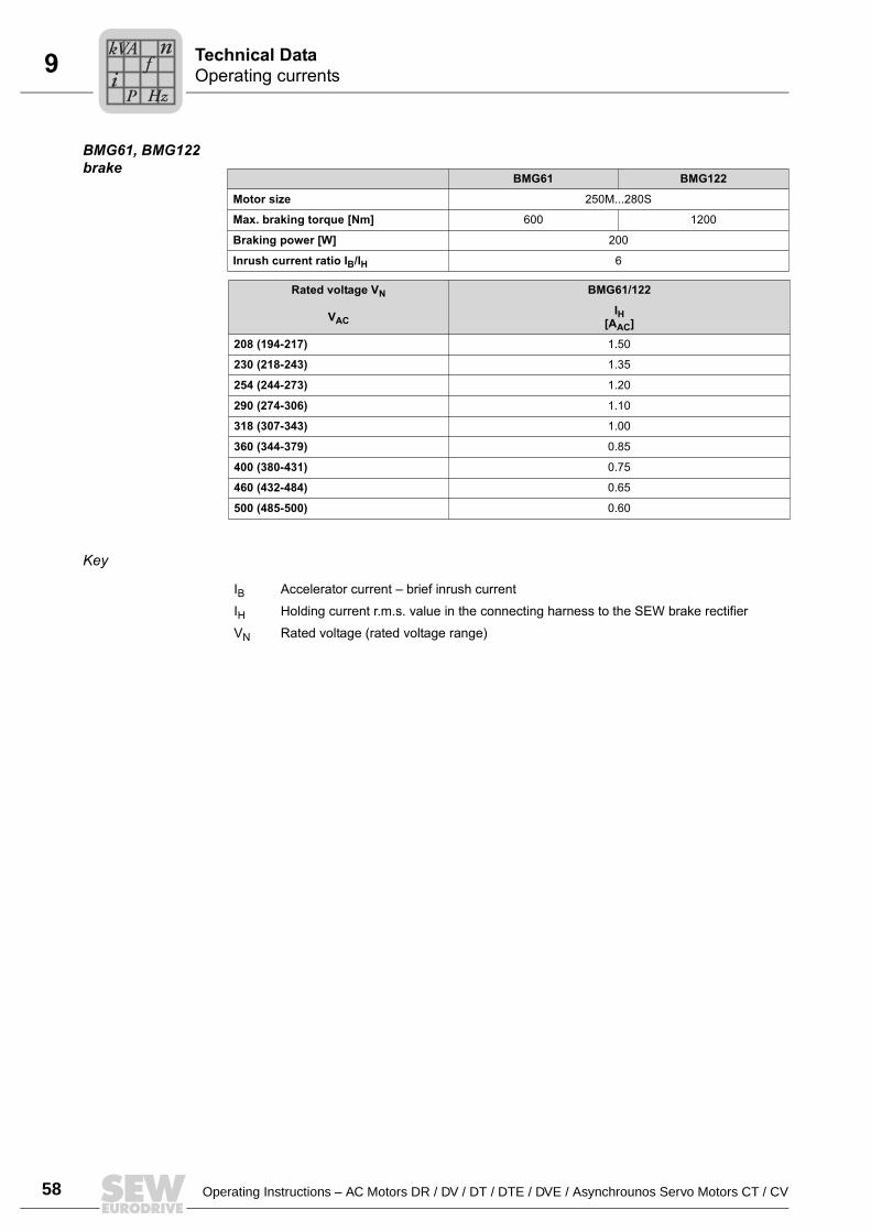
58 Operating Instructions – AC Motors DR / DV / DT / DTE / DVE / Asynchrounos Servo Motors CT / CV
9 Operating currentsTechnical Data
BMG61, BMG122 brake
Key
BMG61 BMG122
Motor size 250M...280S
Max. braking torque [Nm] 600 1200
Braking power [W] 200
Inrush current ratio IB/IH 6
Rated voltage VN BMG61/122
IH[AAC]VAC
208 (194-217) 1.50
230 (218-243) 1.35
254 (244-273) 1.20
290 (274-306) 1.10
318 (307-343) 1.00
360 (344-379) 0.85
400 (380-431) 0.75
460 (432-484) 0.65
500 (485-500) 0.60
IB Accelerator current brief inrush current
IH Holding current r.m.s. value in the connecting harness to the SEW brake rectifier
VN Rated voltage (rated voltage range)
Pi
fkVA
Hz
n
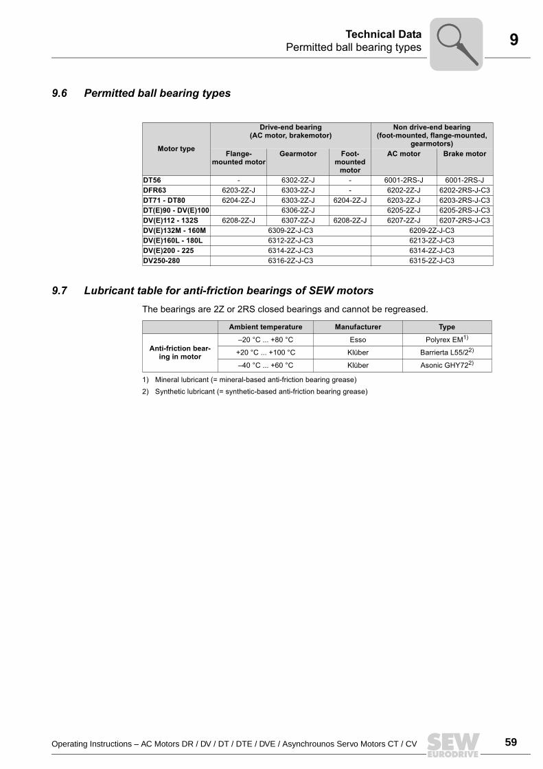
Operating Instructions – AC Motors DR / DV / DT / DTE / DVE / Asynchrounos Servo Motors CT / CV 59
9Permitted ball bearing typesTechnical Data
9.6 Permitted ball bearing types
9.7 Lubricant table for anti-friction bearings of SEW motorsThe bearings are 2Z or 2RS closed bearings and cannot be regreased.
Motor type
Drive-end bearing(AC motor, brakemotor)
Non drive-end bearing(foot-mounted, flange-mounted,
gearmotors)Flange-
mounted motorGearmotor Foot-
mounted motor
AC motor Brake motor
DT56 - 6302-2Z-J - 6001-2RS-J 6001-2RS-JDFR63 6203-2Z-J 6303-2Z-J - 6202-2Z-J 6202-2RS-J-C3DT71 - DT80 6204-2Z-J 6303-2Z-J 6204-2Z-J 6203-2Z-J 6203-2RS-J-C3DT(E)90 - DV(E)100 6306-2Z-J 6205-2Z-J 6205-2RS-J-C3DV(E)112 - 132S 6208-2Z-J 6307-2Z-J 6208-2Z-J 6207-2Z-J 6207-2RS-J-C3DV(E)132M - 160M 6309-2Z-J-C3 6209-2Z-J-C3DV(E)160L - 180L 6312-2Z-J-C3 6213-2Z-J-C3DV(E)200 - 225 6314-2Z-J-C3 6314-2Z-J-C3DV250-280 6316-2Z-J-C3 6315-2Z-J-C3
Ambient temperature Manufacturer Type
Anti-friction bear-ing in motor
20 °C ... +80 °C Esso Polyrex EM1)
1) Mineral lubricant (= mineral-based anti-friction bearing grease)
+20 °C ... +100 °C Klüber Barrierta L55/22)
2) Synthetic lubricant (= synthetic-based anti-friction bearing grease)
40 °C ... +60 °C Klüber Asonic GHY722)
10
60 Operating Instructions DR / DV / DT / DTE / DVE AC Motors / CT / CV Asynchronous Servomotors
Appendix
10 Appendix10.1 Index of changes
The following additions and changes have been made since the last edition of the "DR/DV/DT/DTE/DVE AC Motors, CT/CV Asynchronous Servomotors" operating instruc-tions (publication number: 10567917, Edition 02/2003):
General updates and revisions.
Motor design • Nameplate, unit designation: Example has been changed.
Mechanical installation
• Before you start: Ambient temperature.
Electrical installation
• Using wiring diagrams.• Improving the grounding (EMC).• Ambient conditions during operation.• Connecting the motor: Tightening torques.• Connecting the motor via the plug connectors AB.., AD.., AM.., AS.• Optional equipment: VR forced cooling fan.
Inspection / maintenance
• Inspection / maintenance of the BMG61/122 brake.
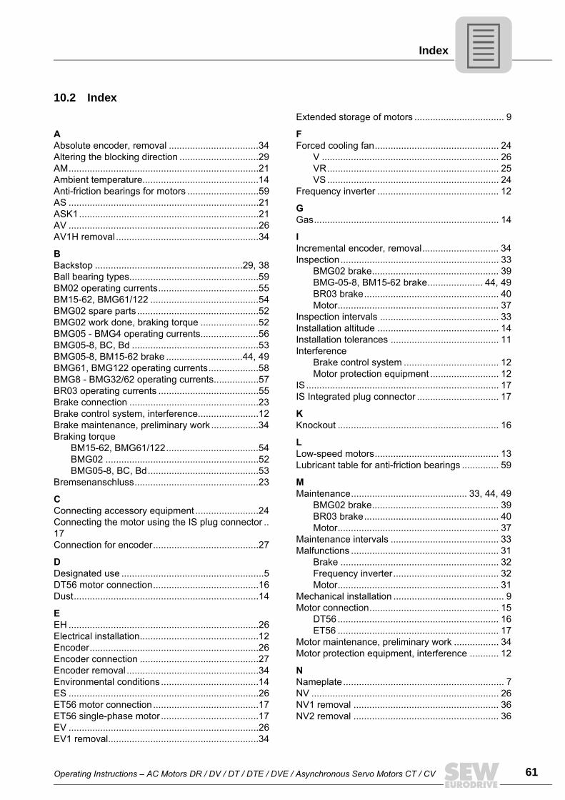
Operating Instructions AC Motors DR / DV / DT / DTE / DVE / Asynchronous Servo Motors CT / CV 61
Index
10.2 Index
AAbsolute encoder, removal ..................................34Altering the blocking direction ..............................29AM........................................................................21Ambient temperature............................................14Anti-friction bearings for motors ...........................59AS ........................................................................21ASK1....................................................................21AV ........................................................................26AV1H removal ......................................................34
BBackstop ........................................................29, 38Ball bearing types.................................................59BM02 operating currents......................................55BM15-62, BMG61/122 .........................................54BMG02 spare parts ..............................................52BMG02 work done, braking torque ......................52BMG05 - BMG4 operating currents......................56BMG05-8, BC, Bd ................................................53BMG05-8, BM15-62 brake .............................44, 49BMG61, BMG122 operating currents...................58BMG8 - BMG32/62 operating currents.................57BR03 operating currents ......................................55Brake connection .................................................23Brake control system, interference.......................12Brake maintenance, preliminary work ..................34Braking torque
BM15-62, BMG61/122...................................54BMG02 ..........................................................52BMG05-8, BC, Bd..........................................53
Bremsenanschluss...............................................23
CConnecting accessory equipment ........................24Connecting the motor using the IS plug connector ..17Connection for encoder........................................27
DDesignated use ......................................................5DT56 motor connection........................................16Dust......................................................................14
EEH ........................................................................26Electrical installation.............................................12Encoder................................................................26Encoder connection .............................................27Encoder removal ..................................................34Environmental conditions.....................................14ES ........................................................................26ET56 motor connection ........................................17ET56 single-phase motor .....................................17EV ........................................................................26EV1 removal.........................................................34
Extended storage of motors .................................. 9
FForced cooling fan............................................... 24
V ................................................................... 26VR................................................................. 25VS ................................................................. 24
Frequency inverter .............................................. 12
GGas...................................................................... 14
IIncremental encoder, removal............................. 34Inspection............................................................ 33
BMG02 brake................................................ 39BMG-05-8, BM15-62 brake..................... 44, 49BR03 brake................................................... 40Motor............................................................. 37
Inspection intervals ............................................. 33Installation altitude .............................................. 14Installation tolerances ......................................... 11Interference
Brake control system .................................... 12Motor protection equipment .......................... 12
IS......................................................................... 17IS Integrated plug connector ............................... 17
KKnockout ............................................................. 16
LLow-speed motors............................................... 13Lubricant table for anti-friction bearings .............. 59
MMaintenance............................................ 33, 44, 49
BMG02 brake................................................ 39BR03 brake................................................... 40Motor............................................................. 37
Maintenance intervals ......................................... 33Malfunctions ........................................................ 31
Brake ............................................................ 32Frequency inverter........................................ 32Motor............................................................. 31
Mechanical installation .......................................... 9Motor connection................................................. 15
DT56 ............................................................. 16ET56 ............................................................. 17
Motor maintenance, preliminary work ................. 34Motor protection equipment, interference ........... 12
NNameplate............................................................. 7NV ....................................................................... 26NV1 removal ....................................................... 36NV2 removal ....................................................... 36
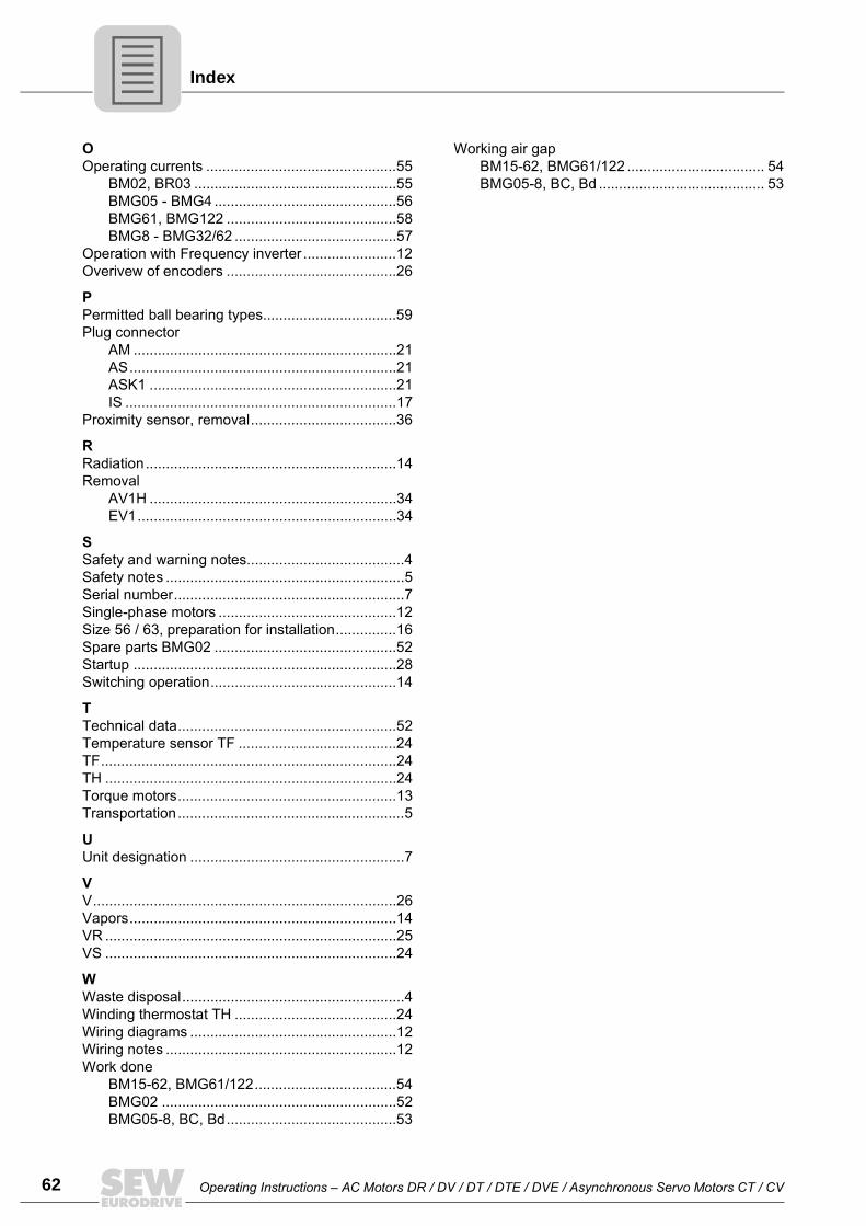
62 Operating Instructions AC Motors DR / DV / DT / DTE / DVE / Asynchronous Servo Motors CT / CV
Index
OOperating currents ...............................................55
BM02, BR03 ..................................................55BMG05 - BMG4 .............................................56BMG61, BMG122 ..........................................58BMG8 - BMG32/62 ........................................57
Operation with Frequency inverter .......................12Overivew of encoders ..........................................26
PPermitted ball bearing types.................................59Plug connector
AM .................................................................21AS..................................................................21ASK1 .............................................................21IS ...................................................................17
Proximity sensor, removal....................................36
RRadiation..............................................................14Removal
AV1H .............................................................34EV1................................................................34
SSafety and warning notes.......................................4Safety notes ...........................................................5Serial number.........................................................7Single-phase motors ............................................12Size 56 / 63, preparation for installation...............16Spare parts BMG02 .............................................52Startup .................................................................28Switching operation..............................................14
TTechnical data......................................................52Temperature sensor TF .......................................24TF.........................................................................24TH ........................................................................24Torque motors......................................................13Transportation........................................................5
UUnit designation .....................................................7
VV...........................................................................26Vapors..................................................................14VR ........................................................................25VS ........................................................................24
WWaste disposal.......................................................4Winding thermostat TH ........................................24Wiring diagrams ...................................................12Wiring notes .........................................................12Work done
BM15-62, BMG61/122...................................54BMG02 ..........................................................52BMG05-8, BC, Bd..........................................53
Working air gapBM15-62, BMG61/122 .................................. 54BMG05-8, BC, Bd ......................................... 53
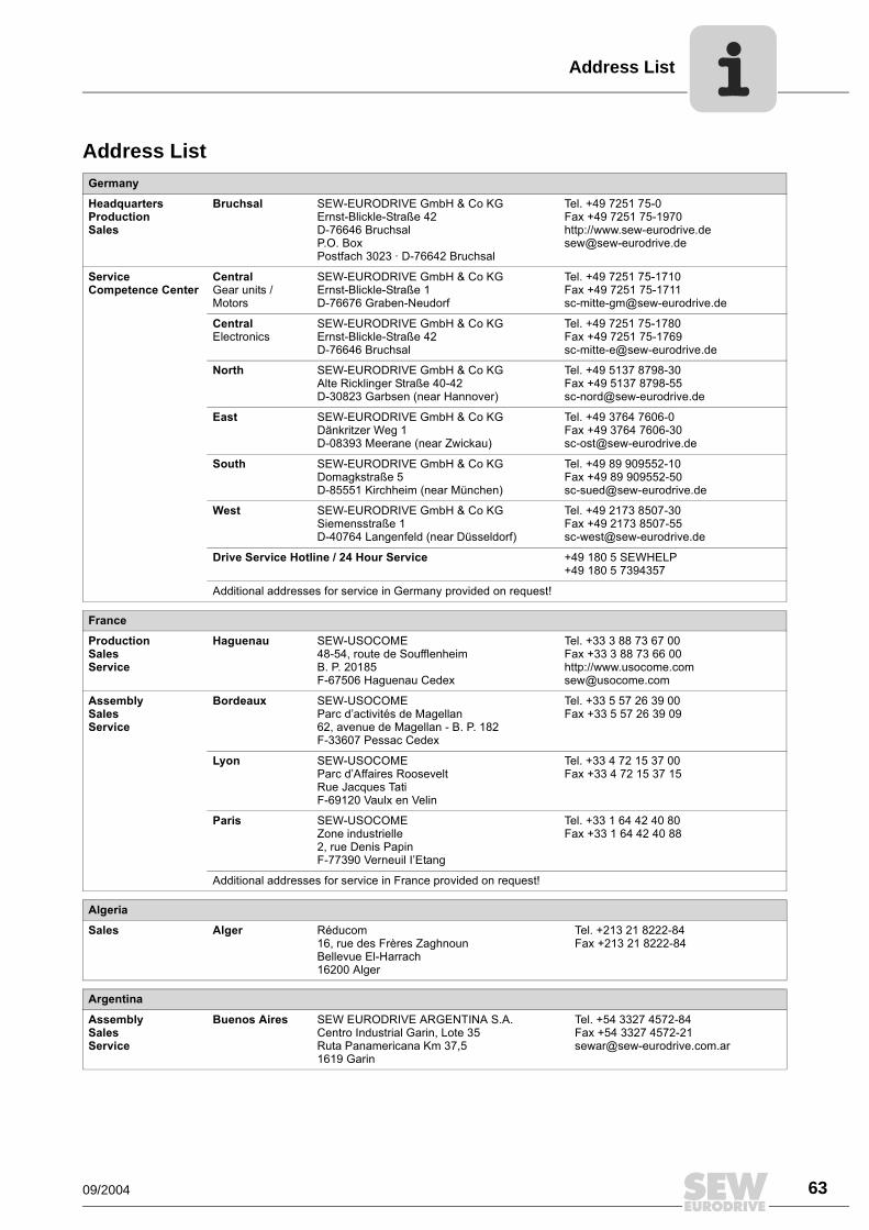
Address List
09/2004 63
Address ListGermany
HeadquartersProductionSales
Bruchsal SEW-EURODRIVE GmbH & Co KGErnst-Blickle-Straße 42 D-76646 BruchsalP.O. BoxPostfach 3023 · D-76642 Bruchsal
Tel. +49 7251 75-0Fax +49 7251 75-1970http://[email protected]
Service Competence Center
Central Gear units / Motors
SEW-EURODRIVE GmbH & Co KGErnst-Blickle-Straße 1 D-76676 Graben-Neudorf
Tel. +49 7251 75-1710Fax +49 7251 [email protected]
Central Electronics
SEW-EURODRIVE GmbH & Co KGErnst-Blickle-Straße 42 D-76646 Bruchsal
Tel. +49 7251 75-1780Fax +49 7251 [email protected]
North SEW-EURODRIVE GmbH & Co KGAlte Ricklinger Straße 40-42 D-30823 Garbsen (near Hannover)
Tel. +49 5137 8798-30Fax +49 5137 [email protected]
East SEW-EURODRIVE GmbH & Co KGDänkritzer Weg 1D-08393 Meerane (near Zwickau)
Tel. +49 3764 7606-0Fax +49 3764 [email protected]
South SEW-EURODRIVE GmbH & Co KGDomagkstraße 5D-85551 Kirchheim (near München)
Tel. +49 89 909552-10Fax +49 89 [email protected]
West SEW-EURODRIVE GmbH & Co KGSiemensstraße 1D-40764 Langenfeld (near Düsseldorf)
Tel. +49 2173 8507-30Fax +49 2173 [email protected]
Drive Service Hotline / 24 Hour Service +49 180 5 SEWHELP+49 180 5 7394357
Additional addresses for service in Germany provided on request!
France
ProductionSalesService
Haguenau SEW-USOCOME 48-54, route de Soufflenheim B. P. 20185F-67506 Haguenau Cedex
Tel. +33 3 88 73 67 00 Fax +33 3 88 73 66 00http://[email protected]
AssemblySalesService
Bordeaux SEW-USOCOME Parc dactivités de Magellan62, avenue de Magellan - B. P. 182F-33607 Pessac Cedex
Tel. +33 5 57 26 39 00Fax +33 5 57 26 39 09
Lyon SEW-USOCOME Parc dAffaires RooseveltRue Jacques TatiF-69120 Vaulx en Velin
Tel. +33 4 72 15 37 00Fax +33 4 72 15 37 15
Paris SEW-USOCOME Zone industrielle 2, rue Denis Papin F-77390 Verneuil IEtang
Tel. +33 1 64 42 40 80Fax +33 1 64 42 40 88
Additional addresses for service in France provided on request!
Algeria
Sales Alger Réducom 16, rue des Frères ZaghnounBellevue El-Harrach16200 Alger
Tel. +213 21 8222-84Fax +213 21 8222-84
Argentina
AssemblySalesService
Buenos Aires SEW EURODRIVE ARGENTINA S.A.Centro Industrial Garin, Lote 35Ruta Panamericana Km 37,51619 Garin
Tel. +54 3327 4572-84Fax +54 3327 [email protected]
Address List
64 09/2004
Australia
AssemblySalesService
Melbourne SEW-EURODRIVE PTY. LTD.27 Beverage DriveTullamarine, Victoria 3043
Tel. +61 3 9933-1000Fax +61 3 9933-1003http://[email protected]
Sydney SEW-EURODRIVE PTY. LTD.9, Sleigh Place, Wetherill Park New South Wales, 2164
Tel. +61 2 9725-9900Fax +61 2 [email protected]
Austria
AssemblySalesService
Wien SEW-EURODRIVE Ges.m.b.H. Richard-Strauss-Strasse 24A-1230 Wien
Tel. +43 1 617 55 00-0Fax +43 1 617 55 00-30http://[email protected]
Belgium
AssemblySalesService
Brüssel CARON-VECTOR S.A.Avenue Eiffel 5B-1300 Wavre
Tel. +32 10 231-311Fax +32 10 231-336http://[email protected]
Brazil
ProductionSalesService
Sao Paulo SEW-EURODRIVE Brasil Ltda.Avenida Amâncio Gaiolli, 50Caixa Postal: 201-07111-970Guarulhos/SP - Cep.: 07251-250
Tel. +55 11 6489-9133Fax +55 11 6480-3328http://[email protected]
Additional addresses for service in Brazil provided on request!
Bulgaria
Sales Sofia BEVER-DRIVE GMBHBogdanovetz Str.1BG-1606 Sofia
Tel. +359 2 9532565Fax +359 2 [email protected]
Cameroon
Sales Douala Electro-ServicesRue Drouot AkwaB.P. 2024Douala
Tel. +237 4322-99Fax +237 4277-03
Canada
AssemblySalesService
Toronto SEW-EURODRIVE CO. OF CANADA LTD. 210 Walker Drive Bramalea, Ontario L6T3W1
Tel. +1 905 791-1553Fax +1 905 791-2999http://[email protected]
Vancouver SEW-EURODRIVE CO. OF CANADA LTD.7188 Honeyman Street Delta. B.C. V4G 1 E2
Tel. +1 604 946-5535Fax +1 604 [email protected]
Montreal SEW-EURODRIVE CO. OF CANADA LTD.2555 Rue Leger Street LaSalle, Quebec H8N 2V9
Tel. +1 514 367-1124Fax +1 514 [email protected]
Additional addresses for service in Canada provided on request!
Chile
AssemblySalesService
Santiago de Chile
SEW-EURODRIVE CHILE LTDA.Las Encinas 1295Parque Industrial Valle GrandeLAMPARCH-Santiago de ChileP.O. BoxCasilla 23 Correo Quilicura - Santiago - Chile
Tel. +56 2 75770-00Fax +56 2 [email protected]
China
ProductionAssemblySalesService
Tianjin SEW-EURODRIVE (Tianjin) Co., Ltd.No. 46, 7th Avenue, TEDA Tianjin 300457
Tel. +86 22 25322612Fax +86 22 [email protected]://www.sew.com.cn
Address List
09/2004 65
AssemblySalesService
Suzhou SEW-EURODRIVE (Suzhou) Co., Ltd.333, Suhong Middle RoadSuzhou Industrial ParkJiangsu Province, 215021P. R. China
Tel. +86 512 62581781Fax +86 512 [email protected]
Colombia
AssemblySalesService
Bogotá SEW-EURODRIVE COLOMBIA LTDA. Calle 22 No. 132-60Bodega 6, Manzana BSantafé de Bogotá
Tel. +57 1 54750-50Fax +57 1 [email protected]
Croatia
SalesService
Zagreb KOMPEKS d. o. o.PIT Erdödy 4 IIHR 10 000 Zagreb
Tel. +385 1 4613-158Fax +385 1 [email protected]
Czech Republic
Sales Praha SEW-EURODRIVE CZ S.R.O.Business Centrum Praha Luná 591CZ-16000 Praha 6 - Vokovice
Tel. +420 220121234 + 220121236Fax +420 220121237http://[email protected]
Denmark
AssemblySalesService
Kopenhagen SEW-EURODRIVEA/SGeminivej 28-30, P.O. Box 100DK-2670 Greve
Tel. +45 43 9585-00Fax +45 43 9585-09http://[email protected]
Estonia
Sales Tallin ALAS-KUUL ASPaldiski mnt.125EE 0006 Tallin
Tel. +372 6593230Fax +372 [email protected]
Finland
AssemblySalesService
Lahti SEW-EURODRIVE OYVesimäentie 4FIN-15860 Hollola 2
Tel. +358 3 589-300Fax +358 3 7806-211http://[email protected]
Gabon
Sales Libreville Electro-ServicesB.P. 1889Libreville
Tel. +241 7340-11Fax +241 7340-12
Great Britain
AssemblySalesService
Normanton SEW-EURODRIVE Ltd.Beckbridge Industrial Estate P.O. Box No.1GB-Normanton, West- Yorkshire WF6 1QR
Tel. +44 1924 893-855Fax +44 1924 893-702http://[email protected]
Greece
SalesService
Athen Christ. Boznos & Son S.A.12, Mavromichali StreetP.O. Box 80136, GR-18545 Piraeus
Tel. +30 2 1042 251-34 Fax +30 2 1042 251-59http://[email protected]
Hong Kong
AssemblySalesService
Hong Kong SEW-EURODRIVE LTD.Unit No. 801-806, 8th FloorHong Leong Industrial ComplexNo. 4, Wang Kwong Road Kowloon, Hong Kong
Tel. +852 2 7960477 + 79604654Fax +852 2 [email protected]
China
Address List
66 09/2004
Hungary
SalesService
Budapest SEW-EURODRIVE Kft.H-1037 BudapestKunigunda u. 18
Tel. +36 1 437 06-58Fax +36 1 437 [email protected]
India
AssemblySalesService
Baroda SEW-EURODRIVE India Pvt. Ltd.Plot No. 4, GidcPor Ramangamdi · Baroda - 391 243Gujarat
Tel. +91 265 2831021Fax +91 265 [email protected]
Technical Offices Bangalore SEW-EURODRIVE India Private Limited308, Prestige Centre Point7, Edward RoadBangalore
Tel. +91 80 22266565Fax +91 80 [email protected]
Mumbai SEW-EURODRIVE India Private Limited312 A, 3rd Floor, Acme PlazaAndheri Kurla Road, Andheri (E)Mumbai
Tel. +91 22 28348440Fax +91 22 [email protected]
Ireland
SalesService
Dublin Alperton Engineering Ltd. 48 Moyle RoadDublin Industrial EstateGlasnevin, Dublin 11
Tel. +353 1 830-6277Fax +353 1 830-6458
Israel
Sales Tel-Aviv Liraz Handasa Ltd. Ahofer Str 34B / 22858858 Holon
Tel. +972 3 5599511Fax +972 3 [email protected]
Italy
AssemblySalesService
Milano SEW-EURODRIVE di R. Blickle & Co.s.a.s.Via Bernini,14 I-20020 Solaro (Milano)
Tel. +39 2 96 9801Fax +39 2 96 [email protected]
Ivory Coast
Sales Abidjan SICASte industrielle et commerciale pour lAfrique165, Bld de MarseilleB.P. 2323, Abidjan 08
Tel. +225 2579-44Fax +225 2584-36
Japan
AssemblySalesService
Toyoda-cho SEW-EURODRIVE JAPAN CO., LTD 250-1, Shimoman-no,Toyoda-cho, Iwata gunShizuoka prefecture, 438-0818
Tel. +81 538 373811Fax +81 538 [email protected]
Korea
AssemblySalesService
Ansan-City SEW-EURODRIVE KOREA CO., LTD. B 601-4, Banweol Industrial Estate Unit 1048-4, Shingil-DongAnsan 425-120
Tel. +82 31 492-8051Fax +82 31 [email protected]
Latvia
Sales Riga SIA Alas-KuulKatlakalna 11CLV-1073 Riga
Tel. +371 7139386Fax +371 [email protected]
Lebanon
Sales Beirut Gabriel Acar & Fils sarlB. P. 80484Bourj Hammoud, Beirut
Tel. +961 1 4947-86 +961 1 4982-72+961 3 2745-39Fax +961 1 4949-71 [email protected]
Address List
09/2004 67
Lithuania
Sales Alytus UAB IrsevaMerkines g. 2ALT-4580 Alytus
Tel. +370 315 79204Fax +370 315 [email protected]
Luxembourg
AssemblySalesService
Brüssel CARON-VECTOR S.A.Avenue Eiffel 5B-1300 Wavre
Tel. +32 10 231-311Fax +32 10 231-336http://[email protected]
Malaysia
AssemblySalesService
Johore SEW-EURODRIVE SDN BHD No. 95, Jalan Seroja 39, Taman Johor Jaya81000 Johor Bahru, JohorWest Malaysia
Tel. +60 7 3549409Fax +60 7 [email protected]
Morocco
Sales Casablanca S. R. M.Société de Réalisations Mécaniques 5, rue Emir Abdelkader05 Casablanca
Tel. +212 2 6186-69 + 6186-70 + 6186-71Fax +212 2 [email protected]
Netherlands
AssemblySalesService
Rotterdam VECTOR Aandrijftechniek B.V. Industrieweg 175 NL-3044 AS RotterdamPostbus 10085NL-3004 AB Rotterdam
Tel. +31 10 4463-700Fax +31 10 4155-552http://[email protected]
New Zealand
AssemblySalesService
Auckland SEW-EURODRIVE NEW ZEALAND LTD. P.O. Box 58-428 82 Greenmount driveEast Tamaki Auckland
Tel. +64 9 2745627Fax +64 9 [email protected]
Christchurch SEW-EURODRIVE NEW ZEALAND LTD. 10 Settlers Crescent, FerrymeadChristchurch
Tel. +64 3 384-6251Fax +64 3 [email protected]
Norway
AssemblySalesService
Moss SEW-EURODRIVE A/SSolgaard skog 71N-1599 Moss
Tel. +47 69 241-020Fax +47 69 [email protected]
Peru
AssemblySalesService
Lima SEW DEL PERU MOTORES REDUCTORES S.A.C.Los Calderos, 120-124Urbanizacion Industrial Vulcano, ATE, Lima
Tel. +51 1 3495280Fax +51 1 [email protected]
Poland
AssemblySalesService
Lodz SEW-EURODRIVE Polska Sp.z.o.o.ul. Techniczna 5 PL-92-518 Lodz
Tel. +48 42 67710-90Fax +48 42 67710-99http://[email protected]
Portugal
AssemblySalesService
Coimbra SEW-EURODRIVE, LDA. Apartado 15 P-3050-901 Mealhada
Tel. +351 231 20 9670Fax +351 231 20 3685http://[email protected]
Romania
SalesService
Bucuresti Sialco Trading SRL str. Madrid nr.4 011785 Bucuresti
Tel. +40 21 230-1328Fax +40 21 230-7170 [email protected]
Address List
68 09/2004
Russia
Sales St. Petersburg ZAO SEW-EURODRIVE P.O. Box 263 RUS-195220 St. Petersburg
Tel. +7 812 5357142 +812 5350430Fax +7 812 5352287http://[email protected]
Senegal
Sales Dakar SENEMECA Mécanique GénéraleKm 8, Route de Rufisque B.P. 3251, Dakar
Tel. +221 849 47-70Fax +221 849 [email protected]
Serbia and Montenegro
Sales Beograd DIPAR d.o.o.Kajmakcalanska 54SCG-11000 Beograd
Tel. +381 11 3046677Fax +381 11 [email protected]
Singapore
AssemblySalesService
Singapore SEW-EURODRIVE PTE. LTD. No 9, Tuas Drive 2 Jurong Industrial Estate Singapore 638644
Tel. +65 68621701 ... 1705Fax +65 [email protected]
Slovakia
Sales Sered SEW-Eurodrive SK s.r.o.Trnavska 920SK-926 01 Sered
Tel. +421 31 7891311Fax +421 31 [email protected]
Slovenia
SalesService
Celje Pakman - Pogonska Tehnika d.o.o.UI. XIV. divizije 14SLO 3000 Celje
Tel. +386 3 490 83-20Fax +386 3 490 [email protected]
South Africa
AssemblySalesService
Johannesburg SEW-EURODRIVE (PROPRIETARY) LIMITEDEurodrive House Cnr. Adcock Ingram and Aerodrome RoadsAeroton Ext. 2Johannesburg 2013P.O.Box 90004Bertsham 2013
Tel. +27 11 248-7000Fax +27 11 [email protected]
Capetown SEW-EURODRIVE (PROPRIETARY) LIMITED Rainbow ParkCnr. Racecourse & Omuramba RoadMontague GardensCape TownP.O.Box 36556Chempet 7442 Cape Town
Tel. +27 21 552-9820Fax +27 21 552-9830Telex 576 [email protected]
Durban SEW-EURODRIVE (PROPRIETARY) LIMITED2 Monaceo PlacePinetownDurbanP.O. Box 10433, Ashwood 3605
Tel. +27 31 700-3451Fax +27 31 [email protected]
Spain
AssemblySalesService
Bilbao SEW-EURODRIVE ESPAÑA, S.L. Parque Tecnológico, Edificio, 302E-48170 Zamudio (Vizcaya)
Tel. +34 9 4431 84-70Fax +34 9 4431 [email protected]
Sweden
AssemblySalesService
Jönköping SEW-EURODRIVE ABGnejsvägen 6-8S-55303 JönköpingBox 3100 S-55003 Jönköping
Tel. +46 36 3442-00Fax +46 36 3442-80http://[email protected]
Address List
09/2004 69
Switzerland
AssemblySalesService
Basel Alfred lmhof A.G.Jurastrasse 10 CH-4142 Münchenstein bei Basel
Tel. +41 61 41717-17Fax +41 61 41717-00http://[email protected]
Thailand
AssemblySalesService
Chon Buri SEW-EURODRIVE (Thailand) Ltd.Bangpakong Industrial Park 2700/456, Moo.7, Tambol DonhuarohMuang DistrictChon Buri 20000
Tel. +66 38 454281Fax +66 38 [email protected]
Tunisia
Sales Tunis T. M.S. Technic Marketing Service7, rue Ibn EI Heithem Z.I. SMMT2014 Mégrine Erriadh
Tel. +216 1 4340-64 + 1 4320-29Fax +216 1 4329-76
Turkey
AssemblySalesService
Istanbul SEW-EURODRIVE Hareket Sistemleri Sirketi Bagdat Cad. Koruma Cikmazi No. 3 TR-34846 Maltepe ISTANBUL
Tel. +90 216 4419163 + 216 4419164 + 216 3838014Fax +90 216 [email protected]
USA
ProductionAssemblySalesService
Greenville SEW-EURODRIVE INC. 1295 Old Spartanburg Highway P.O. Box 518Lyman, S.C. 29365
Tel. +1 864 439-7537Fax Sales +1 864 439-7830Fax Manuf. +1 864 439-9948Fax Ass. +1 864 439-0566Telex 805 550 http://[email protected]
AssemblySalesService
San Francisco SEW-EURODRIVE INC. 30599 San Antonio St.Hayward, California 94544-7101
Tel. +1 510 487-3560Fax +1 510 [email protected]
Philadelphia/PA SEW-EURODRIVE INC. Pureland Ind. Complex 2107 High Hill Road, P.O. Box 481Bridgeport, New Jersey 08014
Tel. +1 856 467-2277Fax +1 856 [email protected]
Dayton SEW-EURODRIVE INC.2001 West Main Street Troy, Ohio 45373
Tel. +1 937 335-0036Fax +1 937 [email protected]
Dallas SEW-EURODRIVE INC.3950 Platinum Way Dallas, Texas 75237
Tel. +1 214 330-4824Fax +1 214 [email protected]
Additional addresses for service in the USA provided on request!
Venezuela
AssemblySalesService
Valencia SEW-EURODRIVE Venezuela S.A.Av. Norte Sur No. 3, Galpon 84-319Zona Industrial Municipal NorteValencia, Estado Carabobo
Tel. +58 241 832-9804Fax +58 241 [email protected]@cantv.net


www.sew-eurodrive.com
How were driving the world
With people whothink fast anddevelop thefuture with you.
With a worldwide service network that isalways close at hand.
With drives and controlsthat automaticallyimprove your productivity.
With comprehensiveknowledge in virtuallyevery branch ofindustry today.
With uncompromisingquality that reduces thecost and complexity ofdaily operations.
With a global presencethat offers responsive and reliable solutions. Anywhere.
With innovativetechnology that solvestomorrows problemstoday.
With online informationand software updates,via the Internet, availablearound the clock.
Gearmotors \ Industrial Gear Units \ Drive Electronics \ Drive Automation \ Services
SEW-EURODRIVEDriving the world
SEW-EURODRIVE GmbH & Co KGP.O. Box 3023 · D-76642 Bruchsal / GermanyPhone +49 7251 75-0 · Fax +49 7251 [email protected]