Embed Size (px)
Citation preview

CABLE
G
GENERATORGIS
SWITCHGEAR
INSULATION
MATERIALS
MOTOR PORTABLE PROTECTIVE
EQUIPMENT
RECLOSERTRANSFORMERCIRCUIT
BREAKER
Specifications are subject to change without notice. Brochure No. 50104
High Power Motor Test Systemsand Equipment
Perform load and no-load testing of all types of • AC and DC motors
• Traction motors
• Synchronous motors
• Induction motors
• Shunt-, Compound-, and Series- Wound motors
Test up to 50,000 HP motors!
High Power Motor Test Systems and Equipment
CABLE
G
GENERATORGIS
SWITCHGEAR
INSULATION
MATERIALS
MOTOR PORTABLE PROTECTIVE
EQUIPMENT
RECLOSERTRANSFORMER
➤ Economical motor testing solution
➤ All controls and instrumentation contained in a single, industrial grade cabinet
➤ Full voltage regulation
Model TM1800-72D
CIRCUIT
BREAKER
TEsTing ApplicATions
DEsign and sAFETY FEATUREs
Specifications are subject to change without notice. Brochure No. 50800
Designed to provide no-load test stand power for multi-horsepower DC Traction Motors
• Main Power Breaker with indicator
• Control Power Breaker with indicator • Security Circuit Interlock Open with indicator
• Emergency OFF Mushroom pushbutton switch
• Zero-start interlock
• External interlock provision
• External warning circuit provision
• Thermal overload protection on all voltage regulator outputs
• Filtered, forced air cooling
• Transient protection on all meters and relays
• Rugged steel cabinet with lifting eyes and removable side panels • Angled control panel with writing desk
• Flashing red warning light
• Output cables included 15’ (4.5 m)
• Recessed jacks for twist-lock plugs on output cables
• Two copies of operation/ maintenance manual
Traction Motor Test set
The Traction Motor Test Set features separate internal sources for field and armature testing and an AC source for testing winding reactance (Impedance Test.) The output supplies each have separate controls, measuring and protection circuits for efficient use of the test set.

RECOGNIZED WORLDWIDE FOR EXCEPTIONAL SERVICE
QUALITY CONSTRUCTION ENSURES RELIABILITY
TECHNOLOGIES
PHENIX
R
2 www.phenixtech.com
Phenix Technologies Electric Motor Test Systems are in operation around the world, providing exceptional service to Motor Manufacturers, Motor Service Shops, Industrial Plants, Electric Utilities, Government Installations.
For over 35 years Phenix Technologies has established worldwide recognition as the leading manufacturer of Motor Test Systems. We have supplied more Motor Test Systems than all other manufacturers combined. Not only does our engineering expertise and manufacturing capabilities provide solutions for customers who may need a custom designed test system for special require-ments, Phenix Technologies continues to introduce new innovations and technology that leaves our competition behind. The Phenix Technologies’ team manufactured and delivered the world’s largest Motor Test System and Core Loss Tester.
Phenix Technologies offers a complete line of electric motor test systems for load and no-load testing of all types of AC and DC motors, traction motors, synchronous motors, induction motors, shunt-wound, compound-wound, and series-wound motors. We have test systems available for testing fractional up to 50,000 HP motors.
When your electric motor testing needs require complete system design and installation, from concept to commissioning, Phenix Technologies is ready to be your project partner.
Each motor test system is equipped with all of the controls, power supplies, metering, and safety/protection devices necessary for efficient testing. Our heavy-duty steel cabinet has removable panels, lifting eyes, slots for fork lifting, and meets NEMA 1 standard for indoor installation. Control panels are primed and painted with a high quality polyurethane gloss finish and have permanently imprinted indicator labels. Our ISO9001 certification ensures optimum standards of quality are met from design through production and verified in final pre-shipment testing procedures.
RANGE OF OPTIONS
• AC, DC, or AC/DC test systems
• Medium or low voltage input options
• Output power up to 10,000 kVA
• Configurations that allow testing of a 10,000 horsepower motor at full load and 50,000 horsepower at no load
• Manual operation, advanced control systems, fully automated testing, custom software solutions, database and report generation
• Precision voltage regulation with the Phenix Column Type Variable Transformer
• “R2” design allows full voltage regulation without interruption which means the motor does not slow down for tap changes
• Highly accurate Voltage, Current, Power, Watts (including Kilowatt- Hours), Vibration, Temperature, and Speed measurement
• Commissioning and training to provide your operator with the information and resources they need for efficient and safe use of your investment
The following information will assist you in choosing the power supplies, features, and options for a motor test system that meets your specific needs. For additional assistance, please consult one of Phenix Technologies Sales Representatives.
Model MTS1500Rwith Swivel BoomMTS R2 Series
Model MTS3750R2-1500
Cover photos courtesy of Integrated Power Services and Baldor Electric Company.
High Power Motor Test Systems and Equipment
CABLE
G
GENERATORGIS
SWITCHGEAR
INSULATION
MATERIALS
MOTOR PORTABLE PROTECTIVE
EQUIPMENT
RECLOSERTRANSFORMER
➤ Economical motor testing solution
➤ All controls and instrumentation contained in a single, industrial grade cabinet
➤ Full voltage regulation
Model TM1800-72D
CIRCUIT
BREAKER
TEsTing ApplicATions
DEsign and sAFETY FEATUREs
Specifications are subject to change without notice. Brochure No. 50800
Designed to provide no-load test stand power for multi-horsepower DC Traction Motors
• Main Power Breaker with indicator
• Control Power Breaker with indicator • Security Circuit Interlock Open with indicator
• Emergency OFF Mushroom pushbutton switch
• Zero-start interlock
• External interlock provision
• External warning circuit provision
• Thermal overload protection on all voltage regulator outputs
• Filtered, forced air cooling
• Transient protection on all meters and relays
• Rugged steel cabinet with lifting eyes and removable side panels • Angled control panel with writing desk
• Flashing red warning light
• Output cables included 15’ (4.5 m)
• Recessed jacks for twist-lock plugs on output cables
• Two copies of operation/ maintenance manual
Traction Motor Test set
The Traction Motor Test Set features separate internal sources for field and armature testing and an AC source for testing winding reactance (Impedance Test.) The output supplies each have separate controls, measuring and protection circuits for efficient use of the test set.

TECHNOLOGIES
PHENIX
R
+1.301.746.8118 3
VOLTAGE REGULATION SYSTEMS
The Phenix Column Type Variable Transformer – Leveraging Your Investment in Test Equipment…
Whether you are an OEM or are in the electric motor repair business, the key to keeping your business running smoothly is reliable equipment. No matter whether you have to test a 50 HP or a 50,000 HP machine, Phenix Technologies Motor Test Systems are synonymous with reliability. The heart of any high power test panel is the voltage regulating system. Phenix Tech-nologies Column Type Variable Transformers (CTVT) have a proven record of performance of over 35 years of service in hundreds of high power motor test field installations. With no sliding contacts to wear or bind, and no sensi-tive power electronics that can fail leading to expensive winding damage, the Phenix CTVT has become the workhorse of the large motor testing industry.
Standard MTS-R Series – Unmatched Reliability and Performance…
Phenix’s standard high power Motor Test Set product line utilizes the CTVT for full range voltage regulation on all output voltage taps. With a turn-to-turn voltage resolution of approximately 0.15%, all Phenix high power Motor Test Sets demonstrate an impressive ability to target and maintain the correct test voltage at the output terminals. Our standard line of high power Motor Test Systems can be designed to operate at 50 or 60 Hz, from any low voltage service up to 600 VAC, at power levels up to 2,500 kVA. The Standard MTS-R Series is capable of performing full load tests on motors rated up to 2,500 HP, and no load tests on motors rated up to 12,500 HP.
MTS-R2 Series – When “Serious” Power is Required…
With over 10 years of service history behind them, the Phenix MTS-R2 series of very high power Motor Test Sets delivers the power to test even the largest electric motors. With the Phenix CTVT applied as the basic voltage regulating element, combined with a multi-tap step-up transformer and a computer controlled on-load switching network, these units are capable of providing uninterrupted voltage from 0 up to 14.4 kVAC. When starting motors in excess of 10,000 HP, maintaining an uninterrupted, regulated voltage during startup is essential to avoiding high inrush currents that could lead to tripping of current limiting devices within the distribution network.
Our MTS-R2 series can be designed to operate at 50 or 60 Hz, from any medium voltage service up to 14.4 kVAC, at power levels up to 10,000 kVA. The MTS-R2 Series is capable of performing full load tests on motors rated up to 10,000 HP, and no load tests on motors rated up to 50,000 HP.
Precise, Balanced Voltage Control – A Must When Making Efficiency Measurements…
Proper efficiency measurements require a balanced set of low distortion, three-phase voltages. Independent, automated phase voltage balancing is available as an option on all Phenix standard MTS-R models, and comes installed as standard equipment on all MTS-R2 series units. With the independent phase balance option installed, you won’t have to make any explanations to your customers to get them to accept the test results for motors tested with unbalanced phase voltages, or waste your time arguing with your electric service provider about your service quality. With ever increasing world energy costs, and a global obligation for all of us to become more wise stewards of the environment, your business can use the power of a Phenix Motor Test System to convince your customers that you are serious when it comes to proving the quality and efficiency of your products and services.
CABLE
G
GENERATORGIS
SWITCHGEAR
INSULATION
MATERIALS
MOTOR PORTABLE PROTECTIVE
EQUIPMENT
RECLOSERTRANSFORMER
➤ Economical motor testing solution
➤ All controls and instrumentation contained in a single, industrial grade cabinet
➤ Full voltage regulation
Model TM1800-72D
CIRCUIT
BREAKER
TEsTing ApplicATions
DEsign and sAFETY FEATUREs
Specifications are subject to change without notice. Brochure No. 50800
Designed to provide no-load test stand power for multi-horsepower DC Traction Motors
• Main Power Breaker with indicator
• Control Power Breaker with indicator • Security Circuit Interlock Open with indicator
• Emergency OFF Mushroom pushbutton switch
• Zero-start interlock
• External interlock provision
• External warning circuit provision
• Thermal overload protection on all voltage regulator outputs
• Filtered, forced air cooling
• Transient protection on all meters and relays
• Rugged steel cabinet with lifting eyes and removable side panels • Angled control panel with writing desk
• Flashing red warning light
• Output cables included 15’ (4.5 m)
• Recessed jacks for twist-lock plugs on output cables
• Two copies of operation/ maintenance manual
Traction Motor Test set
The Traction Motor Test Set features separate internal sources for field and armature testing and an AC source for testing winding reactance (Impedance Test.) The output supplies each have separate controls, measuring and protection circuits for efficient use of the test set.

MOTOR TEST SYSTEM SIZING
TECHNOLOGIES
PHENIX
R
4 www.phenixtech.com
Phenix Technologies Motor Test Systems will typically run 1 HP per kVA of power fully loaded and 5 HP per kVA no-load. For example, a 1000 kVA motor test system is capable of approximate full load testing of a 1000 HP motor and no-load testing of a 5000 HP motor.
MTS-R2 DESIGN – VERY HIGH POWER MOTOR TEST SYSTEMS
Standard Max AC Max Tap Model Load No Load Load No Load Line to Line Tap Current (HP) (HP) (HP) (HP) Voltage (V) (A)
MTS2000R2 2000 10,000 1200 4800 14,400 1200
MTS3000R2 3000 15,000 1200 4800 14,400 1200
MTS3750R2 3750 18,750 1400 5600 14,400 1200
MTS5000R2 5000 25,000 1400 5600 14,400 1200
MTS6500R2 6500 32,500 1750 7000 14,400 1200
MTS7500R2 7500 33,000 1750 7000 14.400 1200
MTS10000R2 10,000 40,000 1750 7000 14,400 1200
NOTE:Input: Up to 15 kV L-LOutput: Up to 14.4 kV L-L maximumAC Motor Load Testing is 1 kVA per 1 Load HP and AC Motor No-Load Testing is 1 kVA per 5 Load HP.
NOTE:Input: 600 V maximumStandard Taps: 240 V, 480 V, 600 V, 1200 V, 2300 V, 3300 V, 4160 VThe 3-phase AC supply is rated for continuous duty and has a 1-minute rated at 250% to allow for high inrush currents during motor start-up.*Currents listed assumes 480 V, 3-phase supply. A separate 115/220 V, 1-phase supply is also required for control power.
Max AC Max Tap Model Input Load No Load Load No Load Line to Line Tap Current Current* (HP) (HP) (HP) (HP) Voltage (V) (A)
MTS300R 375 300 1500 240 1200 14,400 400
MTS500R 625 500 2500 480 1920 14,400 800
MTS750R 925 750 3750 720 2880 14,400 1200
MTS1000R 1250 1000 5000 960 3840 14,400 1200
MTS1250R 1575 1250 6250 1200 4800 14,400 1200
MTS1500R 1875 1500 7500 1350 5400 14.400 1200
MTS2000R 2400 2000 10,000 1750 7000 14,400 1200
MTS2500R 3150 2500 12,500 1750 7000 14,400 1200
Max AC Testing Capability Max DC Testing Capability (Optional)
Max DC Testing Capability (Optional)Max AC Testing Capability
The following testing capabilities are approximate and depend on type and style of the motor to be tested.
High Power Motor Test Systems and Equipment
CABLE
G
GENERATORGIS
SWITCHGEAR
INSULATION
MATERIALS
MOTOR PORTABLE PROTECTIVE
EQUIPMENT
RECLOSERTRANSFORMER
➤ Economical motor testing solution
➤ All controls and instrumentation contained in a single, industrial grade cabinet
➤ Full voltage regulation
Model TM1800-72D
CIRCUIT
BREAKER
TEsTing ApplicATions
DEsign and sAFETY FEATUREs
Specifications are subject to change without notice. Brochure No. 50800
Designed to provide no-load test stand power for multi-horsepower DC Traction Motors
• Main Power Breaker with indicator
• Control Power Breaker with indicator • Security Circuit Interlock Open with indicator
• Emergency OFF Mushroom pushbutton switch
• Zero-start interlock
• External interlock provision
• External warning circuit provision
• Thermal overload protection on all voltage regulator outputs
• Filtered, forced air cooling
• Transient protection on all meters and relays
• Rugged steel cabinet with lifting eyes and removable side panels • Angled control panel with writing desk
• Flashing red warning light
• Output cables included 15’ (4.5 m)
• Recessed jacks for twist-lock plugs on output cables
• Two copies of operation/ maintenance manual
Traction Motor Test set
The Traction Motor Test Set features separate internal sources for field and armature testing and an AC source for testing winding reactance (Impedance Test.) The output supplies each have separate controls, measuring and protection circuits for efficient use of the test set.
TECHNOLOGIES
PHENIX
R
+1.301.746.8118 5
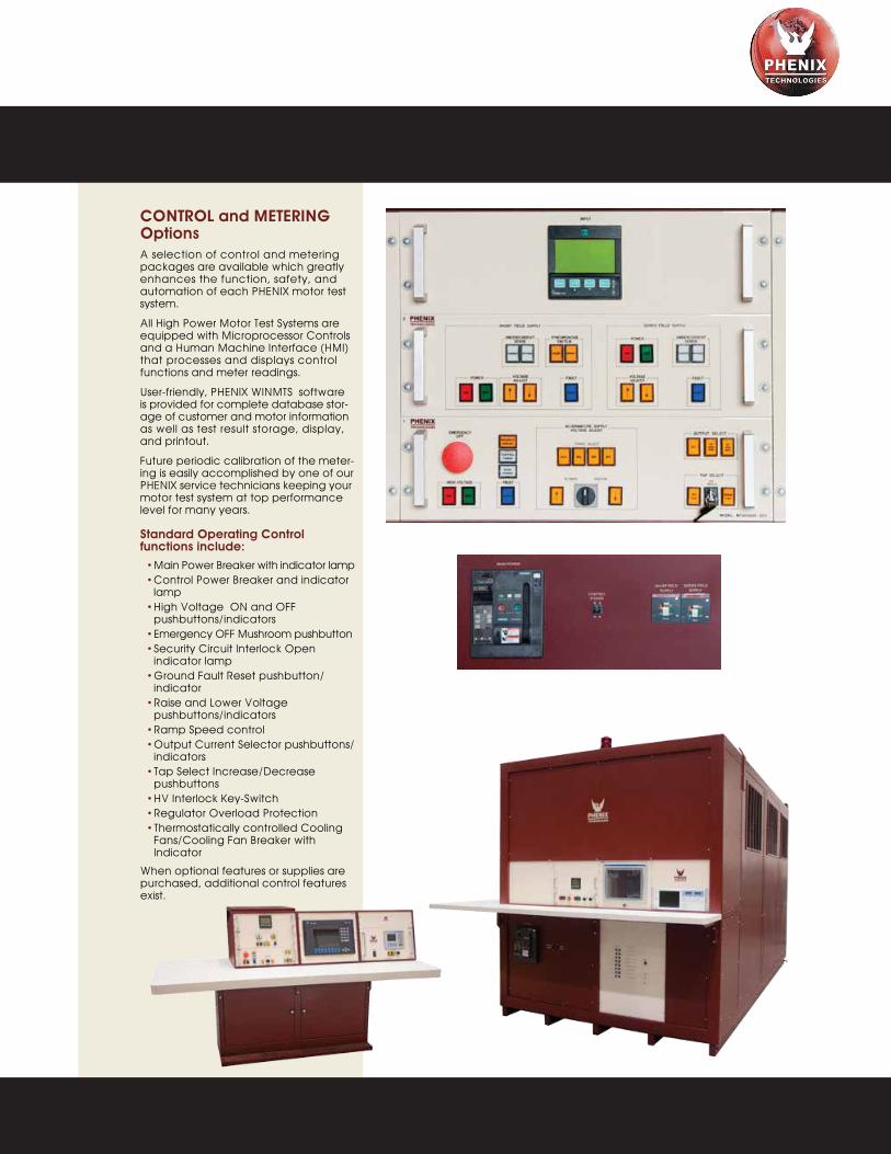
CONTROL and METERING OptionsA selection of control and metering packages are available which greatly enhances the function, safety, and automation of each PHENIX motor test system.
All High Power Motor Test Systems are equipped with Microprocessor Controls and a Human Machine Interface (HMI) that processes and displays control functions and meter readings.
User-friendly, PHENIX WINMTS software is provided for complete database stor-age of customer and motor information as well as test result storage, display, and printout.
Future periodic calibration of the meter-ing is easily accomplished by one of our PHENIX service technicians keeping your motor test system at top performance level for many years.
Standard Operating Control functions include: • Main Power Breaker with indicator lamp • Control Power Breaker and indicator lamp • High Voltage ON and OFF pushbuttons/indicators • Emergency OFF Mushroom pushbutton • Security Circuit Interlock Open indicator lamp • Ground Fault Reset pushbutton/ indicator • Raise and Lower Voltage pushbuttons/indicators • Ramp Speed control • Output Current Selector pushbuttons/ indicators • Tap Select Increase/Decrease pushbuttons • HV Interlock Key-Switch • Regulator Overload Protection • Thermostatically controlled Cooling Fans/Cooling Fan Breaker with Indicator
When optional features or supplies are purchased, additional control features exist.
CABLE
G
GENERATORGIS
SWITCHGEAR
INSULATION
MATERIALS
MOTOR PORTABLE PROTECTIVE
EQUIPMENT
RECLOSERTRANSFORMER
➤ Economical motor testing solution
➤ All controls and instrumentation contained in a single, industrial grade cabinet
➤ Full voltage regulation
Model TM1800-72D
CIRCUIT
BREAKER
TEsTing ApplicATions
DEsign and sAFETY FEATUREs
Specifications are subject to change without notice. Brochure No. 50800
Designed to provide no-load test stand power for multi-horsepower DC Traction Motors
• Main Power Breaker with indicator
• Control Power Breaker with indicator • Security Circuit Interlock Open with indicator
• Emergency OFF Mushroom pushbutton switch
• Zero-start interlock
• External interlock provision
• External warning circuit provision
• Thermal overload protection on all voltage regulator outputs
• Filtered, forced air cooling
• Transient protection on all meters and relays
• Rugged steel cabinet with lifting eyes and removable side panels • Angled control panel with writing desk
• Flashing red warning light
• Output cables included 15’ (4.5 m)
• Recessed jacks for twist-lock plugs on output cables
• Two copies of operation/ maintenance manual
Traction Motor Test set
The Traction Motor Test Set features separate internal sources for field and armature testing and an AC source for testing winding reactance (Impedance Test.) The output supplies each have separate controls, measuring and protection circuits for efficient use of the test set.

TESTING SOFTWARE
TECHNOLOGIES
PHENIX
R
6 www.phenixtech.com
Combining the control system with our testing software creates a very user friendly system which provides complete documentation and reporting for each motor tested. Two data bases are created, one of all of your clients and a second of all motors.
*Software is compatible with ACS motor shop software.
The Main Screen of WinMTS provides direct access to your customer and motor records.
High Power Motor Test Systems and Equipment
CABLE
G
GENERATORGIS
SWITCHGEAR
INSULATION
MATERIALS
MOTOR PORTABLE PROTECTIVE
EQUIPMENT
RECLOSERTRANSFORMER
➤ Economical motor testing solution
➤ All controls and instrumentation contained in a single, industrial grade cabinet
➤ Full voltage regulation
Model TM1800-72D
CIRCUIT
BREAKER
TEsTing ApplicATions
DEsign and sAFETY FEATUREs
Specifications are subject to change without notice. Brochure No. 50800
Designed to provide no-load test stand power for multi-horsepower DC Traction Motors
• Main Power Breaker with indicator
• Control Power Breaker with indicator • Security Circuit Interlock Open with indicator
• Emergency OFF Mushroom pushbutton switch
• Zero-start interlock
• External interlock provision
• External warning circuit provision
• Thermal overload protection on all voltage regulator outputs
• Filtered, forced air cooling
• Transient protection on all meters and relays
• Rugged steel cabinet with lifting eyes and removable side panels • Angled control panel with writing desk
• Flashing red warning light
• Output cables included 15’ (4.5 m)
• Recessed jacks for twist-lock plugs on output cables
• Two copies of operation/ maintenance manual
Traction Motor Test set
The Traction Motor Test Set features separate internal sources for field and armature testing and an AC source for testing winding reactance (Impedance Test.) The output supplies each have separate controls, measuring and protection circuits for efficient use of the test set.

MRC Hybrid Ceramic Ball Bearings
TECHNOLOGIES
PHENIX
R
+1.301.746.8118 7
PRECISE INSTRUMENTATION
OPTIONS AVAILABLE • Additional Output Taps
• AC Output Phase Balance Compensation for motor test systems with column-type transformers only
• AC Phase Reversal Switch
• DC Armature and Shunt Field Power Supplies
• DC Series Field Power Supply
• DC Armature Reversal Switch
• Synchronous Motor Shorting Switch
• Wattmeter
• Off-Zero Bypass
• Multi-function Input Meter displays voltage, current, power factor, kVA, kW
• Physical Measurement Instrumentation: - Vibration Measurement - Thermocouple Temperature Measurement - RTD Temperature Measurement - Tachometer/Optical Speed Measurement
• Computer and Printer
• Remote Control Console with Writing Desk and Interconnect Cables
• Remote Output Cubicle to locate output connection near test area
• Swivel Jib Boom for Output Leads
• Longer Interconnect Cables
• Dynamometer Interface / Control Mounting
The test system has a complete instrumentation package for definitive measurement of electrical and physical characteristics of motors under test. All meters for AC and DC supplies are digital and displayed on the Human Machine Interface. High accuracy current transformers (CT), potential transformers (PT) and transducers are utilized for stability and a high degree of meter accuracy. All meters are calibrated with stan-dards traceable to NIST/NRC and a calibration sticker is affixed to the control panel faceplate.
The meter readings displayed are determined by the model of the test set and options selected.
The following meters have a 5-digit display and Accuracy is ± 0.5% of range ± Least Significant Digit (LSD)
Standard meters included for AC supplies • Three-Phase AC Output Voltmeters displaying phases A-B, B-C, C-A • Three-Phase AC Output Currentmeters displaying phases A, B, C
Optional meters • DC Armature Output Voltmeter • DC Armature Output Currentmeter • DC Field Output Voltmeter • DC Field Output Currentmeter • DC Series Field Output Voltmeter • DC Series Field Output Currentmeter • Three-Phase Wattmeter
Optional physical measurement metering • Vibration Monitor, Range: 0-10.00 mil (displacement)/0-0.3 in/sec (velocity), Accuracy ± 1% of Range +LSD • Temperature Meter, Range: 0-200.0°C (32.0- 392.0°F), Accuracy: ± 1° • Tachometer, Range: 0-9,999 RPM, Accuracy ±1 RPM
CABLES
Input: N/A ( input connection is at main circuit breaker )
Output: 15’ (5 m) output cables for all supplies with twist-lock connectors on one end and ring terminals with rubber boots on opposite end
Optional Remote Console: 15’ (5 m) interconnect cables
Optional Temperature Thermocouple: 15’ (5 m)
Optional Speed Measurement: 15’ (5 m)
AC Test
DC Test
CABLE
G
GENERATORGIS
SWITCHGEAR
INSULATION
MATERIALS
MOTOR PORTABLE PROTECTIVE
EQUIPMENT
RECLOSERTRANSFORMER
➤ Economical motor testing solution
➤ All controls and instrumentation contained in a single, industrial grade cabinet
➤ Full voltage regulation
Model TM1800-72D
CIRCUIT
BREAKER
TEsTing ApplicATions
DEsign and sAFETY FEATUREs
Specifications are subject to change without notice. Brochure No. 50800
Designed to provide no-load test stand power for multi-horsepower DC Traction Motors
• Main Power Breaker with indicator
• Control Power Breaker with indicator • Security Circuit Interlock Open with indicator
• Emergency OFF Mushroom pushbutton switch
• Zero-start interlock
• External interlock provision
• External warning circuit provision
• Thermal overload protection on all voltage regulator outputs
• Filtered, forced air cooling
• Transient protection on all meters and relays
• Rugged steel cabinet with lifting eyes and removable side panels • Angled control panel with writing desk
• Flashing red warning light
• Output cables included 15’ (4.5 m)
• Recessed jacks for twist-lock plugs on output cables
• Two copies of operation/ maintenance manual
Traction Motor Test set
The Traction Motor Test Set features separate internal sources for field and armature testing and an AC source for testing winding reactance (Impedance Test.) The output supplies each have separate controls, measuring and protection circuits for efficient use of the test set.

www.phenixtech.com © Copyright – Phenix Technologies, Inc. 1/2015
Branch OfficesPhenix Systems AGRiehenstrasse 62A, 4058 Basel, SwitzerlandPh: +41.61.383.2770 • Fx: [email protected]
Phenix AsiaZhong Cheng Rd, Sec 1, No 177, 2F, Taipei 11148 TaiwanPh: +886.2.2835.9738 • Fx: [email protected]
World HeadquartersPhenix Technologies, Inc.
75 Speicher DriveAccident, MD 21520 USA
Ph: +1.301.746.8118Fx: +1.301.895.5570
High Voltage • High Current • High Power Test Systems and Components
TECHNOLOGIES
PHENIX
R
ISO 9001CERTIFIED
PHENIX Technologies is committed to providing leadership, innovation,technology, quality, and service in all areas of our business.
Our 80,000 square-foot headquarters is a modern manufacturing facility.All aspects of electrical, mechanical, and software design and production are performed in this facility and controlled by an ISO9001 certified quality
program. Our engineers offer a unique blend of theoretical knowledge and practical experience. Our Service and Calibration Department assists
customers during and after installation to ensure years of trouble free service.
We carry our commitment into the future as we proudly continue to provide the best in high voltage, high current, high power test systems
and components.
Other motor testing products PHENIX offers:
• Low Power Motor Test Systems • Water-Brake Dynamometers
• Core Loss Testers • Insulation Analyzers
• AC Hipots • Megohmmeters
• DC Hipots • Microhmmeters
www.eis-inc.com
CABLE
G
GENERATORGIS
SWITCHGEAR
INSULATION
MATERIALS
MOTOR PORTABLE PROTECTIVE
EQUIPMENT
RECLOSERTRANSFORMER
➤ Economical motor testing solution
➤ All controls and instrumentation contained in a single, industrial grade cabinet
➤ Full voltage regulation
Model TM1800-72D
CIRCUIT
BREAKER
TEsTing ApplicATions
DEsign and sAFETY FEATUREs
Specifications are subject to change without notice. Brochure No. 50800
Designed to provide no-load test stand power for multi-horsepower DC Traction Motors
• Main Power Breaker with indicator
• Control Power Breaker with indicator • Security Circuit Interlock Open with indicator
• Emergency OFF Mushroom pushbutton switch
• Zero-start interlock
• External interlock provision
• External warning circuit provision
• Thermal overload protection on all voltage regulator outputs
• Filtered, forced air cooling
• Transient protection on all meters and relays
• Rugged steel cabinet with lifting eyes and removable side panels • Angled control panel with writing desk
• Flashing red warning light
• Output cables included 15’ (4.5 m)
• Recessed jacks for twist-lock plugs on output cables
• Two copies of operation/ maintenance manual
Traction Motor Test set
The Traction Motor Test Set features separate internal sources for field and armature testing and an AC source for testing winding reactance (Impedance Test.) The output supplies each have separate controls, measuring and protection circuits for efficient use of the test set.
BRANCHESAtlanta GA 800.447.0135Birmingham AL 800.829.8642Bluefield VA 800.959.5424Charlotte NC 800.235.9491Chicago IL 800.347.5407Cincinnati OH 800.347.7495Cleveland OH 800.347.8991Dallas TX 800.786.7033Denver CO 800.347.2740
El Paso TX 800.548.1354Harlingen TX 956.364.2700Houston TX 800.347.3380Londonderry NH 888.327.8347Los Angeles CA 800.347.9601Memphis TN 800.766.7866Miami FL 800.524.0180Milwaukee WI 262.404.6020Minneapolis MN 800.328.4662Oklahoma City OK 800.654.6631
Oklahoma City (IWI) 405.942.0693Orlando FL 888.235.4584Philadelphia PA 800.367.1212Phoenix AZ 800.347.2740San Francisco CA 800.347.9611Seattle WA 800.347.6303Syracuse NY 888.521.0909
CANADA Toronto 844.789.0343
MEXICO Guadalajara 011.52.333.165.5445 Monterrey 011.52.818.321.3388 Tijuana 011.52.664.625.4835
PUERTO RICO Carolina 787.757.6565
1110
2015