Embed Size (px)
Citation preview
FLUDEX®
StrömungskupplungenFluid CouplingsCoupleurs hydrauliques
K481 DE/EN/FR2
FLUDEXStrömungskupplungen Fluid Couplings Coupleurs hydrauliques
Inhaltsübersicht Contents Sommaire
Inhaltsübersicht: Seite
Vorteile und Einsatzgebiete 3
Aufbau und Wirkungsweise 4
Baureihe FA 5
Baureihen FG, FV 6
Baureihe FN 7
Technische Angaben zur Auswahl undGrößenbestimmung 8 + 9
Nennleistungen 10
Kennlinienbeispiele 11
Explosionsschutz nach ATEX 95 11
FLUDEX-Kupplungen als Anlaufhilfefür IEC-Motoren, n = 1500 min-1 12
FLUDEX-Kupplungen als Anlaufhilfefür IEC-Motoren, n = 3000 min-1 13
Maße, Gewichte undmaximale Ölfüllungen
Bauarten FAD, FAE 14
Bauarten FADB, FADS 15
Bauart FAR 16
Bauarten FAO, FAM 17
Bauarten FGD, FGE, FGM 18
Bauarten FVD, FVE, FVM 19
Bauarten FGO, FVO 20
Bauarten FNO, FNA, FND 21
Bauart FNDB 22
Bauart FNDS 23
Elektronische Betriebskontrolle 24
Mechanische Betriebskontrolle 25
Technische Hinweise für den Einbau 26 + 27
ISO-Passungen, Wellenenden,Paßfedern und Zentrierbohrungen 28
Zwischenverkauf der “ab Flender-Vorratslagerlieferbar” gekennzeichneten Erzeugnisse bleibtvorbehalten.
Die in den Tafeln angegebenen Gewichte sindunverbindliche Mittelwerte, Abbildungen nichtstreng verbindlich. Maßänderungen bei Weiter-entwicklung sowie Änderung technischer Anga-ben möglich.
Diese technische Unterlage hat gesetzlichenSchutz (DIN 34)
Contents: Page
Features and fields of application 3
Design and operation 4
FA series 5
FG and FV series 6
FN series 7
Technical data for the selectionof size 8 + 9
Nominal power ratings 10
Examples of characteristic curves 11
Explosion protection according to ATEX 95 11
FLUDEX couplings as starting aidfor IEC motors, n = 1500 min-1 12
FLUDEX couplings as starting aidfor IEC motors, n = 3000 min-1 13
Dimensions, weights andmax. oil quantities
Types FAD, FAE 14
Types FADB, FADS 15
Type FAR 16
Types FAO, FAM 17
Types FGD, FGE, FGM 18
Types FVD, FVE, FVM 19
Types FGO, FVO 20
Types FNO, FNA, FND 21
Type FNDB 22
Type FNDS 23
Electronic operating control system 24
Mechanical operating control system 25
Practical hints for fitting 26 + 27
ISO fits, shaft ends, parallel keysand centre holes 28
Products marked “available ex Flender stock”are subject to prior sale.
The weights shown in the tables are mean valuesand, like the illustrations, are not strictly binding.Dimensions and technical specifications aresubject to change at any time due to furtherdevelopment.
This brochure is protected by copyright.
Sommaire: Page
Avantages et domaines d’application 3
Construction et fonctionnement 4
Série FA 5
Séries FG, FV 6
Série FN 7
Données techniques pour le choixet la détermination de la taille 8 + 9
Puissances nominales 10
Exemples de courbes caractéristiques 11
Atmosphères explosives selon ATEX 95 11
Sélection coupleurs FLUDEX pourmoteurs IEC, n = 1500 min-1 12
Sélection coupleurs FLUDEX pourmoteurs IEC, n = 3000 min-1 13
Dimensions, poids etquantité d’huile maximale
Types FAD, FAE 14
Types FADB, FADS 15
Type FAR 16
Types FAO, FAM 17
Types FGD, FGE, FGM 18
Types FVD, FVE, FVM 19
Types FGO, FVO 20
Types FNO, FNA, FND 21
Type FNDB 22
Type FNDS 23
Dispositif de surveillance électronique 24
Dispositif de surveillance mécanique 25
Conseils techniques de montage 26 + 27
Tolérances ISO, bouts d’arbres,clavettes et centrages 28
Les articles portant la mention “livrable du stockFlender” sont disponibles sauf vente entretemps.
Les poids indiqués dans les tableaux sont desvaleurs moyennes données à titre indicatif, lesillustrations sont sans engagement. Nous nousréservons le droit de modifier des dimensions oudes données techniques en fonction des perfec-tionnements.
Cette notice technique est protégée par la loi(DIN 34).
K481 DE/EN/FR 3
FLUDEXStrömungskupplungen Fluid Couplings Coupleurs hydrauliques
Vorteile und Einsatzgebiete Features and Fields of Application Avantages et applications
Die FLUDEX-Kupplung ist eine hydrodyna-mische Strömungskupplung, die nach demFöttinger-Prinzip arbeitet. Die Kupplungsteilevon An- und Abtriebsseite sind mechanischnicht miteinander verbunden und somit ver-schleißfrei. Die Drehmomentübertragung erfolgtüber die in der Kupplung rotierende Ölfüllung,die über radial angeordnete Schaufeln geführtwird. FLUDEX-Kupplungen besitzen die charak-teristischen Eigenschaften von Strömungs-maschinen. Das Drehmoment wächst mit demQuadrat und die Leistung mit der dritten Potenzder Antriebsdrehzahl. Bei der stationärenDrehmomentübertragung stellt sich ein geringerBetriebsschlupf ein.
Die hydrodynamische Drehmomentübertragungbei Einsatz der FLUDEX-Kupplung bietet fol-gende Vorteile:
� Sanftes und stoßfreies Anfahren von Maschi-nen und Förderanlagen.
� Beschleunigung von sehr großen Massenohne Verwendung von überdimensioniertenMotoren.
� Entlasteter und verkürzter Motoranlauf, dadas Kupplungsdrehmoment mit dem Quadratder Motordrehzahl wächst. Geringe Motor-erwärmung, da der hohe Anfahrstrom nurkurzzeitig auftritt.
� Anfahren von hochbelasteten Maschinendurch Asynchronmotoren auch mit flacherMotorkennlinie (Spannungsabfall, Hochspan-nungsmotoren) unter Ausnutzung des Motor-kippmomentes.
� Drehmomentbegrenzung beim Anfahren vonFörderbändern, Drehmomentenanpassung anBandbeladung bei Vorkammerkupplungen.
� Überlastbegrenzung im Blockadefall (Schau-felradantriebe, Mischer), nach Überschreitungdes Grenzdrehmomentes abfallende Dreh-momentencharakteristik, kein Abwürgen desMotors.
� Verschleißfreie Drehmomentübertragung, daAn- und Abtriebsseite mechanisch nicht mit-einander verbunden sind.
� Ausgezeichnete Schwingungstrennung undStoßdämpfung, weitestgehende Drehschwin-gungsentkopplung in schwingungsgefährde-ten Antrieben (PTO-Antriebe, Antriebe mitDieselmotoren).
� Schutz des Antriebes vor Belastungsspitzenbei häufigen Schaltvorgängen und bei Rever-sierbetrieb.
� Belastungsausgleich bei Mehrmotorenan-trieben durch Schlupffähigkeit und Füllungs-anpassung, zeitlich versetztes Anfahren derMotoren zur Reduzierung der Anfahrdreh-momente und zur Vermeidung gleichzeitigauftretender Einschaltstromspitzen.
� Geringer Betriebsschlupf der Kupplung beiNennlast.
� Einfache Einstellung des übertragbaren Dreh-momentes über die Füllung.
� Bei Überlastung Absicherung der Kupplungs-füllung über elektronisch oder mechanischwirkende thermische Überwachungseinrich-tungen möglich.
� Bei Einsatz im Bergbau (Untertage) Wasser-befüllung der Kupplung in Sonderausführungmöglich.
FLUDEX couplings are hydrodynamic fluidcouplings operating according to the Föttingerprinciple. The coupling parts on the input and out-put side are not mechanically connected andthus not subject to wear. Torque is transmittedby the oil movement in the coupling, acceleratedby the radial blades. FLUDEX couplings havethe same characteristics as turbines. Torque in-creases with the second power, and power capa-city is propertional to the third power of inputspeed. During stationary torque transmissionlittle operating slip occurs.
Hydrodynamic torque transmission via a FLUDEXcoupling shows the following advantages:
� Soft and shockless starting of machines andconveyors;
� Acceleration of very large masses without thenecessity to use overdimensioned motors;
� Load relieved and faster motor start sincecoupling torque grows proportional to thesecond power of motor speed. Negligibleheating-up of motor, as the high starting currentis only drawn for a short time;
� Starting of heavily loaded machines byinduction motors also with flat motor charac-teristic (voltage drop, high voltage motors) byutilizing the motor pull-out torque;
� Limitation of torque when starting conveyorbelts; adaptation of torque to belt load if delaychamber coupling is used;
� Overload limitation in case of a drive blockage(bucket wheel drives, mixer drives); fallingtorque characteristic when maximum torquehas been exceeded; no motor stalling;
� Torque is transmitted without causing wearsince input and output side are not mechani-cally connected;
� Excellent vibration separation and shockdamping, greatest possible extent of torsio-nal vibration uncoupling in drives subject tovibration (PTO drives, Diesel engine drives);
� Protection of drive against peak loads in caseof frequent starting and reversing operations;
� Load compensation in multi-motor drives owingto ability to slip and variation in filling level, suc-cessive starting of motors to reduce startingtorques and avoid simultaneous startingcurrent peaks;
� Little operating slip of couplings at nominalload;
� Easy adjustment of transmittable torque byvarying the fluid level;
� In case of overload, protection of fluid filling ispossible by electronic or mechanical thermalcontrol devices;
� For underground mining applications, wateras operating medium is possible in a specialcoupling design.
Le coupleur hydraulique FLUDEX est un coupleurhydrodynamique à circulation de fluide selon leprincipe de Föttinger. Les parties du coupleurcôté entrée et sortie ne sont pas reliées mécani-quement donc elles ne sont pas soumises àl’usure. La transmission du couple résulte d’untransfert de fluide circulant dans les chambres,avec des lamelles radiales dans les deux partiesdu coupleur. Les coupleurs FLUDEX ont les pro-priétés caractéristiques des machines hydrauli-ques. L’augmentation du couple est proportion-nelle au carré de la vitesse d’entrée et celle de lapuissance à la vitesse d’entrée élevée à la puis-sance 3. Lorsque la transmission du couple eststationnaire, on a un faible glissement.
L’utilisation du coupleur FLUDEX avec transmis-sion hydrodynamique du couple présente lesavantages suivants:
� Démarrage en douceur et sans à-coups desmachines et des convoyeurs.
� Accélération de masses très importantes sansavoir recours à des moteurs surdimensionnés.
� Démarrage sans charge et plus court du mo-teur puisque le couple du coupleur augmenteproportionellement au carré de la vitesse dumoteur. Faible échauffement du moteur puis-que le courant élevé de démarrage n’est que decourte durée.
� Démarrage de machines très chargées avecdes moteurs asynchrones ainsi qu’avecdes moteurs aux caractéristiques médiocres(baisse de tension, moteurs à haute tension)en utilisant le couple maximal du moteur.
� Limitation du couple de démarrage des convoy-eurs à bandes, adaption du couple en fonctionde la charge de la bande pour les coupleursmuni d’une chambre de retardement.
� Limitation de la surcharge en cas de blocage(entraînement de pales, de mélangeurs), aprèsdépassement du couple limite la caractéristi-que du couple décroît, pas d’étranglement dumoteur.
� Transmission du couple sans usure car lesdeux parties (entrée et sortie) ne sont pasreliées entre elles de façon mécanique.
� Excellente séparation des vibrations torsio-nelles et amortissement de chocs, possibilitéencore plus étendue de séparer les vibrationstorsionnelles dans les systèmes d’entraîne-ment le plus exposés aux vibrations (entraîne-ments PTO, moteurs Diesel).
� Protection du système d’entraînement contreles pointes en charge lors des démarragesfréquents ou en cas d’inversion de sens derotation.
� Capacité de glissement et répartition descharges lors de l’entraînement par plusieursmoteurs et régulation du remplissage, démar-rage échelonné des moteurs pour réduire lescouples de démarrage en évitant des pointesde courant simultanées au démarrage.
� Faible glissement du coupleur en chargenominale.
� Réglage facile du couple à transmettre enfonction du remplissage.
� En cas de surcharge possibilité de surveil-lance du remplissage par des dispositifs desurveillance thermique électroniques ou méca-niques.
� Dans le cadre de l’utilisation dans les mines(fonds) possibilité de remplissage des coup-leurs en exécution spéciale avec de l’eau.
K481 DE/EN/FR4
FLUDEXStrömungskupplungen Fluid Couplings Coupleurs hydrauliques
Aufbau und Wirkungsweise Design and Operation Construction et fonctionnement
Die vorteilhaften Eigenschaften der FLUDEX-Kupplungen werden in vielfältigen Einsatzge-bieten genutzt, z.B. für folgende Anlagen:Förderanlagen, Gurtförderbänder, Verladeein-richtungen, Aufbereitungsanlagen, Becherwerke,Kettenförderer, Schaufelradantriebe, Brecher,Hilfsantriebe für Mühlen, Rollenpressen, Trom-melantriebe, Windsichter, Ventilatoren, Gebläse,Mischer, Rührwerke, Kneter, Zentrifugen, Dekan-ter, Pumpen, Kompressoren, Generatorantriebe(PTO), Schiffsantriebe, Schredder, Extruder,Karusellantriebe, Fahrzeugantriebe.
FLUDEX-Kupplungen sind in den BaureihenFA, FG, FV und FN für Leistungen bis 2500 kWlieferbar. Insgesamt stehen 14 gut gestaffelteBaugrößen zur Verfügung, die in Kombinationmit Keilriemenscheiben, elastischen N-EUPEX-Kupplungen und Bremsscheiben vielfältigeEinbaumöglichkeiten bieten.
Aufbau und WirkungsweiseDie FLUDEX-Kupplungen bestehen aus wenigenrobusten Teilen. Zu den Innenteilen gehört dieHohlwelle oder Vollwelle (Teil 106), mit der dasSchaufelrad (105) verbunden ist. Das Außenge-häuse setzt sich aus dem Deckel (102) und derSchaufelschale (101), die über eine Flanschver-schraubung miteinander verbunden sind, zusam-men. Das Außengehäuse und die Hohlwelle sindzweifach ineinander gelagert und durch Wellen-dichtringe nach außen abgedichtet. Zur Befüllungder Kupplung sind zwei Einfüllschrauben (153)in Einfüllöffnungen mit integrierter Überfüllabsi-cherung und zum Absichern gegen Überhitzungeine oder zwei Schmelzsicherungsschrauben(103) in das Kupplungsgehäuse eingebracht. DieSchmelzsicherungsschrauben dienen gleichzei-tig als Ölablaßschrauben und können über eineauf das Kupplungsgehäuse eingebrachte Skalie-rung als Füllstandskontrolle genutzt werden.
Bei Blockierung und Überlastung durch die Ar-beitsmaschine erwärmt sich die Kupplung, bis dieSchmelztemperatur der Sicherung erreicht ist.Durch das Ansprechen der Schmelzsicherung ent-weicht die Ölfüllung, und der Antriebsmotor wirdvon der Arbeitsmaschine getrennt, so daß einemögliche Zerstörung der Kupplung durch Überhit-zung oder Überdruck vermieden wird. Um das Ab-spritzen der Ölfüllung zu verhindern, können elek-tronisch oder mechanisch gesteuerte thermischeÜberwachungseinrichtungen eingesetzt werden.
FLUDEX-Kupplungen dürfen maximal bis zu 85%des Gesamtvolumens gefüllt werden (Begren-zung durch Überfüllabsicherung). Höhere Füllun-gen führen infolge der größeren temperaturab-hängigen Volumenausdehnung von Öl gegenüberdem Aluminiumgehäuse zu einem starken Druck-anstieg in der Kupplung, der zu einer Zerstörung(Aufbrechen) der Kupplung führen kann, bevor dieAnsprechtemperatur der Schmelzsicherungs-schrauben erreicht wird.
FLUDEX-Kupplungen arbeiten nach dem Föttin-ger-Prinzip. Bei Antrieb z.B. über die Hohlwellewirkt das Schaufelrad als Pumpe und die Schau-felschale als Turbine. Die von dem Motor an dasSchaufelrad abgegebene Leistung erzeugt indem Arbeitsraum (8) eine von innen nach außengerichtete und über radial angeordnete Schaufelngeführte Rotationsströmung. Die Strömungsener-gie der Kupplungsfüllung wird durch die abtriebs-seitige Schaufelschale wieder in mechanischeLeistung umgesetzt und über eine elastischeKupplung (9) oder eine Riemenscheibe (120) andie Maschine weitergeleitet. Die zur Drehmo-mentübertragung erforderliche Rotationsströ-mung bedingt einen kleinen Betriebsschlupf. DieLeistungsfähigkeit einer Strömungskupplungsteigt mit dem Schlupf, mit der dritten Potenz derAntriebsdrehzahl, mit der Kupplungsbefüllung(Masse der wirksamen Flüssigkeit) und mitder Größe des Wirkdurchmessers (fünftePotenz) der Kupplung.
Owing to their advantageous properties, FLUDEXcouplings can be used over a wide range ofapplications, for example in:Hoisting equipment, conveyor belts, loadingplants, processing plants, bucket elevators, chainconveyors, bucket wheel drives, breakers, auxi-liary drives for mills, roller presses, drum drives,air separators, fans, blowers, mixers, agitators,kneaders, centrifuges, pumps, decanters, com-pressors, generator drives (PTO), marine drives,shredders, extruders, rotary drives, vehicledrives.
FLUDEX couplings of the FA, FG, FV, and FNseries are available for power ratings up to2500 kW in 14 well graded sizes, which, in com-bination with V-belt pulleys, flexible N-EUPEXcouplings and brake disks, offer a wide variety ofinstallation possibilities.
Design and operationFLUDEX couplings consist of only a few sturdycomponents: the splined hollow or solid shaft(part 106) on which the impeller (105) ismounted. The outer housing is formed by thecover (102) and the blade wheel housing(101) connected by a bolted flange joint. Outerhousing and hollow shaft have double bearingsupport and are sealed off to the outside by shaftseals. The housing is provided with two fillerplugs (153) with integral overflow protectionand two fusible safety plugs (103) for protectionagainst overheating. The fusible safety plugsalso serve as oil drain plugs and can be utilizedas level indicator with the aid of a scale markingon the housing.
In case of blockage or overload condition of thedriven machine, the coupling heats up until themelting temperature of the fuse is reached.The fluid is then discharged and the prime moverisolated from the driven machine, preventingpossible destruction of the coupling through over-heating or excess pressure. Fluid discharge canbe prevented by fitting electronically or mechani-cally controlled monitoring devices.
FLUDEX couplings may be filled up to max. 85%of their volume (limitation by overflow protection).Excessive fillings result in a strong increase ofpressure in the coupling due to the increasedtemperature-dependent volume expansion ofoil which may lead to destruction (breaking open)of the coupling before the response temperatureof the fusible safety plugs is reached.
FLUDEX couplings operate according to theFöttinger principle. If driven, for example, via thehollow shaft, the impeller acts as a pump and theblade wheel housing as a turbine. The impellerwith its radial blades driven by the motor producesfluid acceleration in outward direction. The flowenergy of the fluid is transformed again intomechanical power through the blade wheelhousing on the output side and is transferredto the driven machine via a flexible coupling (9) ora V-belt pulley (120). The rotational fluid flownecessary for torque transmission causes littleoperational slip on the turbine side. Power capa-city of a fluid coupling related to the amount ofslip is proportional to the third power of input(impeller) speed, dimension of effective couplingdiameter (fifth power), and fluid filling (mass ofeffective fluid).
Les propriétés avantageuses des coupleursFLUDEX sont utilisées dans de nombreuxdomaines d’application comme par exemple:Les convoyeurs, les convoyeurs à bandes, les in-stallations de déchargement, traitement des mine-rais, élévateurs à godets, convoyeurs à chaînes,entraînement de pales, broyeurs, entraînementsauxiliaires de concasseurs, presses à rouleaux,entraînement de tambours, criblage (tamisage),ventilateurs, souffleries, éoliennes, mélangeurs,agitateurs,malaxeurs, centrifugeuses,décanteurs,pompes, compresseurs, génératrices (PTO), sys-tèmes d’entraînement maritimes, shredders, extru-deuses, entraînement de manèges, de véhicules.On peut livrer les coupleurs FLUDEX FA, FG,FV et FN pour des puissances allant jusqu’à2500 kW. En tout 14 tailles bien échelonnéesqui, combinées avec poulies trapézoïdales, avecdes accouplements élastiques N-EUPEX oudes disques de frein, offrent une multitude depossibilités de montage.
Montage et principe de fonctionnementLes coupleurs FLUDEX se composent d’un petitnombre de pièces robustes. Les pièces internescomprennent l’arbre creux ou l’arbre plein rep.(106), sur lequel est monté le rotor de turbine (105)avec une cannelure. Le carter extérieur se composedu couvercle (102) et du rotor de pompe (101) reliésensemble par des flasques boulonnés. Le carterextérieur et l’arbre creux sont reliés doublement pardes paliers à roulements et protégés de l’extérieurpar des bagues d’éanchéité. Pour le remplissage,on a placé sur le carter deux bouchons de remplis-sage (153) servant également de protection contrele débordement ainsi que deux bouchons fusibles(103) comme protection contre l’échauffement. Lesbouchons fusibles servent à la fois de bouchons devidange et peuvent être utilisés comme contrôleursde niveau lorsqu’on ajoute une graduation sur lecarter.
En cas de blocage ou de surcharge de lamachine, le coupleur s’échauffe jusqu’à ce quela température de fusion du fusible soit atteinte.Lorsque le fusible est sollicité, le fluide s’échappeet le moteur d’entraînement est séparé de lamachine entraînée, évitant ainsi la destructiondu coupleur par surchauffe ou par surpression.Pour empêcher l’huile de gicler, il est possibled’installer des dispositifs de surveillance électro-niques ou mécaniques.
Ne remplir les coupleurs FLUDEX qu’à 85% duvolume global (limitation par sécurité trop-plein).Des remplissages plus importants provoqueraientune trop forte montée de pression dans le carteren alu en raison de l’augmentation de volume dufluide due à la chaleur, ce qui pourrait entraîner ladestruction du coupleur (éclatement) avant que latempérature de fusion des bouchons fusibles nesoit atteinte.
Les coupleurs FLUDEX travaillent selon le prin-cipe de Föttinger. Lorsque l’entraînement se faitpar ex. l’arbre creux, le rotor de turbine agitcomme une pompe et le rotor de pompe commeun turbine. La puissance transmise par le moteurau rotor de turbine produit un courant giratoiredu fluide entraîné par les lamelles des deux par-ties du coupleur dans la chambre de travail (8) del’intérieur vers l’extérieur. L’énergie produite par leremplissage du coupleur est transformée en puis-sance mécanique par le rotor de pompe à la sortieet est transmise à la machine entraînée par l’inter-médiaire d’un accouplement élastique (9) oud’une poulie (120). Le courant giratoire néces-saire à la transmission du couple produit un légerglissement (différence du vitesse entre les deuxparties du coupleur). La puissance d’un coupleurhydraulique augmente avec le glissement, de lavitesse d’entrée élevée à la puissance 3 avecremplissage normal du coupleur (fonction de lamasse du fluide) ainsi qu’avec la taille du diamètreeffective du coupleur (élevé à la puissance 5).
K481 DE/EN/FR 5
FLUDEXStrömungskupplungen Fluid Couplings Coupleurs hydrauliques
Baureihe FA FA Series Série FA
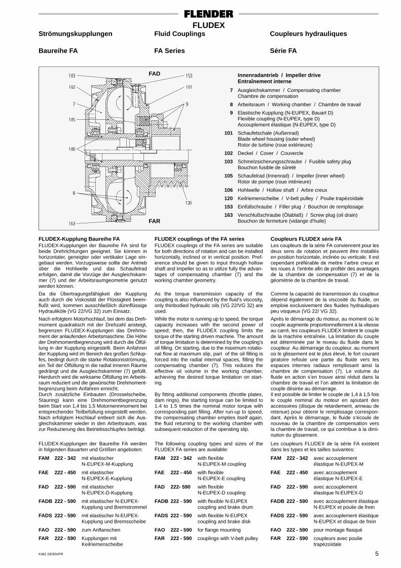
Innenradantrieb / Impeller driveEntraînement interne
7 Ausgleichskammer / Compensating chamberChambre de compensation
8 Arbeitsraum / Working chamber / Chambre de travail
9 Elastische Kupplung (N-EUPEX, Bauart D)Flexible coupling (N-EUPEX, type D)Accouplement élastique (N-EUPEX, type D)
101 Schaufelschale (Außenrad)Blade wheel housing (outer wheel)Rotor de turbine (roue extérieure)
102 Deckel / Cover / Couvercle
103 Schmelzsicherungsschraube / Fusible safety plugBouchon fusible de sûreté
105 Schaufelrad (Innenrad) / Impeller (inner wheel)Rotor de pompe (roue intérieure)
106 Hohlwelle / Hollow shaft / Arbre creux
120 Keilriemenscheibe / V-belt pulley / Poulie trapézoïdale
153 Einfüllschraube / Filler plug / Bouchon de remplissage
163 Verschlußschraube (Ölablaß) / Screw plug (oil drain)Bouchon de fermeture (vidange d’huile)
FAD
FAR
FLUDEX-Kupplung Baureihe FAFLUDEX-Kupplungen der Baureihe FA sind fürbeide Drehrichtungen geeignet. Sie können inhorizontaler, geneigter oder vertikaler Lage ein-gebaut werden. Vorzugsweise sollte der Antriebüber die Hohlwelle und das Schaufelraderfolgen, damit die Vorzüge der Ausgleichskam-mer (7) und der Arbeitsraumgeometrie genutztwerden können.
Da die Übertragungsfähigkeit der Kupplungauch durch die Viskosität der Flüssigkeit beein-flußt wird, kommen ausschließlich dünnflüssigeHydrauliköle (VG 22/VG 32) zum Einsatz.
Nach erfolgtem Motorhochlauf, bei dem das Dreh-moment quadratisch mit der Drehzahl ansteigt,begrenzen FLUDEX-Kupplungen das Drehmo-ment der anlaufenden Arbeitsmaschine. Die Höheder Drehmomentbegrenzung wird durch die Ölfül-lung in der Kupplung eingestellt. Beim Anfahrender Kupplung wird im Bereich des großen Schlup-fes, bedingt durch die starke Rotationsströmung,ein Teil der Ölfüllung in die radial inneren Räumegedrängt und die Ausgleichskammer (7) gefüllt.Hierdurch wird die wirksame Ölfüllung im Arbeits-raum reduziert und die gewünschte Drehmoment-begrenzung beim Anfahren erreicht.Durch zusätzliche Einbauten (Drosselscheibe,Stauring) kann eine Drehmomentbegrenzungbeim Start von 1,4 bis 1,5 Motornennmoment beientsprechender Teilbefüllung eingestellt werden.Nach erfolgtem Hochlauf entleert sich die Aus-gleichskammer wieder in den Arbeitsraum, waszur Reduzierung des Betriebsschlupfes beiträgt.
FLUDEX-Kupplungen der Baureihe FA werdenin folgenden Bauarten und Größen angeboten:
FAM 222 - 342 mit elastischerN-EUPEX-M-Kupplung
FAE 222 - 450 mit elastischerN-EUPEX-E-Kupplung
FAD 222 - 590 mit elastischerN-EUPEX-D-Kupplung
FADB 222 - 590 mit elastischer N-EUPEX-Kupplung und Bremstrommel
FADS 222 - 590 mit elastischer N-EUPEX-Kupplung und Bremsscheibe
FAO 222 - 590 zum Anflanschen
FAR 222 - 590 Kupplungen mitKeilriemenscheibe
FLUDEX couplings of the FA seriesFLUDEX couplings of the FA series are suitablefor both directions of rotation and can be installedhorizontally, inclined or in vertical position. Pref-erence should be given to input through hollowshaft and impeller so as to utilize fully the advan-tages of compensating chamber (7) and theworking chamber geometry.
As the torque transmission capacity of thecoupling is also influenced by the fluid’s viscosity,only thinbodied hydraulic oils (VG 22/VG 32) areused.
While the motor is running up to speed, the torquecapacity increases with the second power ofspeed; then, the FLUDEX coupling limits thetorque of the starting driven machine. The amountof torque limitation is determined by the coupling’soil filling. On starting, due to the maximum rotatio-nal flow at maximum slip, part of the oil filling isforced into the radial internal spaces, filling thecompensating chamber (7). This reduces theeffective oil volume in the working chamber,achieving the desired torque limitation on start-ing.
By fitting additional components (throttle plates,dam rings), the starting torque can be limited to1.4 to 1.5 times the nominal motor torque withcorresponding part filling. After run-up to speed,the compensating chamber empties itself again,the fluid returning to the working chamber withsubsequent reduction of the operating slip.
The following coupling types and sizes of theFLUDEX FA series are available:
FAM 222 - 342 with flexibleN-EUPEX-M coupling
FAE 222 - 450 with flexibleN-EUPEX-E coupling
FAD 222- 590 with flexibleN-EUPEX-D coupling
FADB 222 - 590 with flexible N-EUPEXcoupling and brake drum
FADS 222 - 590 with flexible N-EUPEXcoupling and brake disk
FAO 222 - 590 for flange mounting
FAR 222 - 590 couplings with V-belt pulley
Coupleurs FLUDEX série FALes coupleurs de la série FA conviennent pour lesdeux sens de rotation et peuvent être installésen position horizontale, inclinée ou verticale. Il estcependant préférable de mettre l’arbre creux etles roues à l’entrée afin de profitér des avantagesde la chambre de compensation (7) et de lagéométrie de la chambre de travail.
Comme la capacité de transmission du coupleurdépend également de la viscosité du fluide, onemploie exclusivement des fluides hydrauliquespeu visqueux (VG 22/ VG 32).
Après le démarrage du moteur, au moment où lecouple augmente proportionnellement à la vitesseau carré, les coupleurs FLUDEX limitent le couplede la machine entraînée. La limitation du coupleest déterminée par le niveau du fluide dans lecoupleur. Au démarrage du coupleur, au momentoù le glissement est le plus élevé, le fort courantgiratoire refoule une partie du fluide vers lesespaces internes radiaux remplissant ainsi lachambre de compensation (7). Le volume dufluide en action s’en trouve ainsi réduit dans lachambre de travail et l’on atteint la limitation decouple désirée au démarrage.Il est possible de limiter le couple de 1,4 à 1,5 foisle couple nominal du moteur en ajoutant desaccessoires (disque de retardement, anneau deretenue) pour obtenir le remplissage correspon-dant. Après le démarrage, le fluide s’écoule denouveau de la chambre de compensation versla chambre de travail, ce qui contribue à la dimi-nution du glissement.
Les coupleurs FLUDEX de la série FA existentdans les types et les tailles suivantes:
FAM 222 - 342 avec accouplementélastique N-EUPEX-M
FAE 222 - 450 avec accouplementélastique N-EUPEX-E
FAD 222 - 590 avec accouplementélastique N-EUPEX-D
FADB 222 - 590 avec accouplement élastiqueN-EUPEX et poulie de frein
FADS 222 - 590 avec accouplement élastiqueN-EUPEX et disque de frein
FAO 222 - 590 pour montage flasqué
FAR 222 - 590 coupleurs avec poulietrapézoïdale
K481 DE/EN/FR6
FLUDEXStrömungskupplungen Fluid Couplings Coupleurs hydrauliques
Baureihen FG / FV FG and FV Series Séries FG / FV
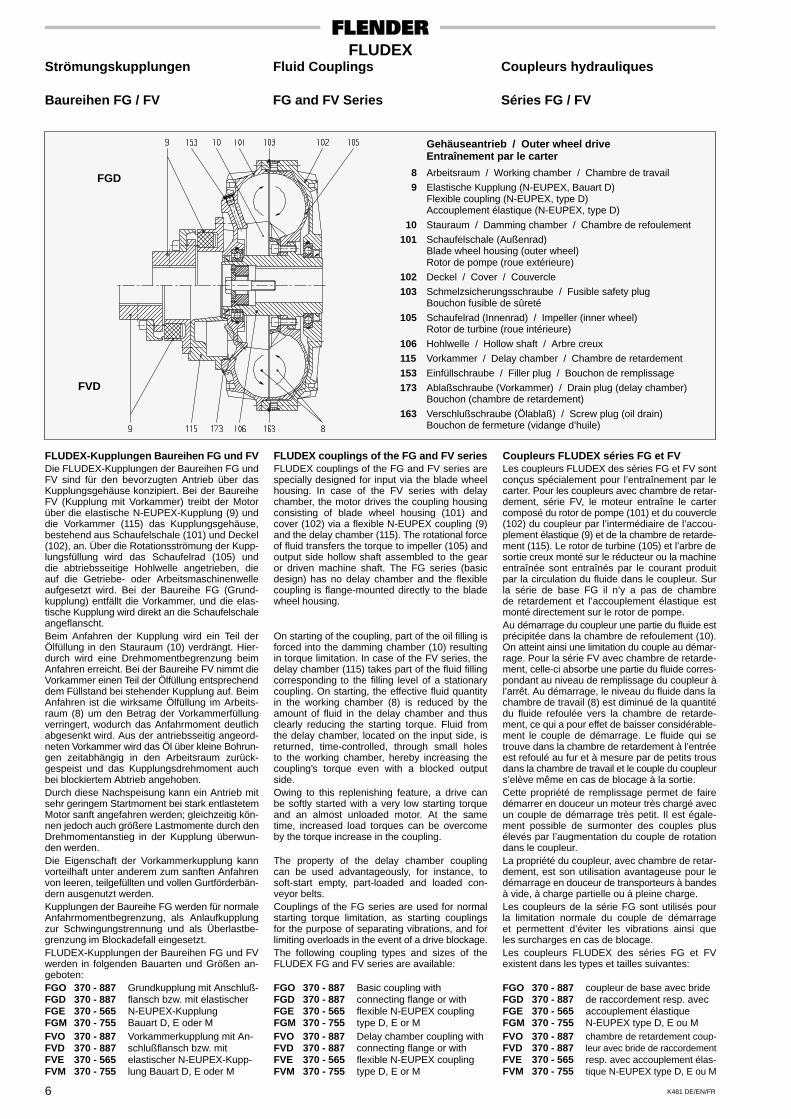
Gehäuseantrieb / Outer wheel driveEntraînement par le carter
8 Arbeitsraum / Working chamber / Chambre de travail
9 Elastische Kupplung (N-EUPEX, Bauart D)Flexible coupling (N-EUPEX, type D)Accouplement élastique (N-EUPEX, type D)
10 Stauraum / Damming chamber / Chambre de refoulement
101 Schaufelschale (Außenrad)Blade wheel housing (outer wheel)Rotor de pompe (roue extérieure)
102 Deckel / Cover / Couvercle
103 Schmelzsicherungsschraube / Fusible safety plugBouchon fusible de sûreté
105 Schaufelrad (Innenrad) / Impeller (inner wheel)Rotor de turbine (roue intérieure)
106 Hohlwelle / Hollow shaft / Arbre creux
115 Vorkammer / Delay chamber / Chambre de retardement
153 Einfüllschraube / Filler plug / Bouchon de remplissage
173 Ablaßschraube (Vorkammer) / Drain plug (delay chamber)Bouchon (chambre de retardement)
163 Verschlußschraube (Ölablaß) / Screw plug (oil drain)Bouchon de fermeture (vidange d’huile)
FGD
FVD
FLUDEX-Kupplungen Baureihen FG und FVDie FLUDEX-Kupplungen der Baureihen FG undFV sind für den bevorzugten Antrieb über dasKupplungsgehäuse konzipiert. Bei der BaureiheFV (Kupplung mit Vorkammer) treibt der Motorüber die elastische N-EUPEX-Kupplung (9) unddie Vorkammer (115) das Kupplungsgehäuse,bestehend aus Schaufelschale (101) und Deckel(102), an. Über die Rotationsströmung der Kupp-lungsfüllung wird das Schaufelrad (105) unddie abtriebsseitige Hohlwelle angetrieben, dieauf die Getriebe- oder Arbeitsmaschinenwelleaufgesetzt wird. Bei der Baureihe FG (Grund-kupplung) entfällt die Vorkammer, und die elas-tische Kupplung wird direkt an die Schaufelschaleangeflanscht.Beim Anfahren der Kupplung wird ein Teil derÖlfüllung in den Stauraum (10) verdrängt. Hier-durch wird eine Drehmomentbegrenzung beimAnfahren erreicht. Bei der Baureihe FV nimmt dieVorkammer einen Teil der Ölfüllung entsprechenddem Füllstand bei stehender Kupplung auf. BeimAnfahren ist die wirksame Ölfüllung im Arbeits-raum (8) um den Betrag der Vorkammerfüllungverringert, wodurch das Anfahrmoment deutlichabgesenkt wird. Aus der antriebsseitig angeord-neten Vorkammer wird das Öl über kleine Bohrun-gen zeitabhängig in den Arbeitsraum zurück-gespeist und das Kupplungsdrehmoment auchbei blockiertem Abtrieb angehoben.Durch diese Nachspeisung kann ein Antrieb mitsehr geringem Startmoment bei stark entlastetemMotor sanft angefahren werden; gleichzeitig kön-nen jedoch auch größere Lastmomente durch denDrehmomentanstieg in der Kupplung überwun-den werden.Die Eigenschaft der Vorkammerkupplung kannvorteilhaft unter anderem zum sanften Anfahrenvon leeren, teilgefüllten und vollen Gurtförderbän-dern ausgenutzt werden.Kupplungen der Baureihe FG werden für normaleAnfahrmomentbegrenzung, als Anlaufkupplungzur Schwingungstrennung und als Überlastbe-grenzung im Blockadefall eingesetzt.FLUDEX-Kupplungen der Baureihen FG und FVwerden in folgenden Bauarten und Größen an-geboten:FGO 370 - 887 Grundkupplung mit Anschluß-FGD 370 - 887 flansch bzw. mit elastischerFGE 370 - 565 N-EUPEX-KupplungFGM 370 - 755 Bauart D, E oder MFVO 370 - 887 Vorkammerkupplung mit An-FVD 370 - 887 schlußflansch bzw. mitFVE 370 - 565 elastischer N-EUPEX-Kupp-FVM 370 - 755 lung Bauart D, E oder M
FLUDEX couplings of the FG and FV seriesFLUDEX couplings of the FG and FV series arespecially designed for input via the blade wheelhousing. In case of the FV series with delaychamber, the motor drives the coupling housingconsisting of blade wheel housing (101) andcover (102) via a flexible N-EUPEX coupling (9)and the delay chamber (115). The rotational forceof fluid transfers the torque to impeller (105) andoutput side hollow shaft assembled to the gearor driven machine shaft. The FG series (basicdesign) has no delay chamber and the flexiblecoupling is flange-mounted directly to the bladewheel housing.
On starting of the coupling, part of the oil filling isforced into the damming chamber (10) resultingin torque limitation. In case of the FV series, thedelay chamber (115) takes part of the fluid fillingcorresponding to the filling level of a stationarycoupling. On starting, the effective fluid quantityin the working chamber (8) is reduced by theamount of fluid in the delay chamber and thusclearly reducing the starting torque. Fluid fromthe delay chamber, located on the input side, isreturned, time-controlled, through small holesto the working chamber, hereby increasing thecoupling’s torque even with a blocked outputside.Owing to this replenishing feature, a drive canbe softly started with a very low starting torqueand an almost unloaded motor. At the sametime, increased load torques can be overcomeby the torque increase in the coupling.
The property of the delay chamber couplingcan be used advantageously, for instance, tosoft-start empty, part-loaded and loaded con-veyor belts.Couplings of the FG series are used for normalstarting torque limitation, as starting couplingsfor the purpose of separating vibrations, and forlimiting overloads in the event of a drive blockage.The following coupling types and sizes of theFLUDEX FG and FV series are available:
FGO 370 - 887 Basic coupling withFGD 370 - 887 connecting flange or withFGE 370 - 565 flexible N-EUPEX couplingFGM 370 - 755 type D, E or MFVO 370 - 887 Delay chamber coupling withFVD 370 - 887 connecting flange or withFVE 370 - 565 flexible N-EUPEX couplingFVM 370 - 755 type D, E or M
Coupleurs FLUDEX séries FG et FVLes coupleurs FLUDEX des séries FG et FV sontconçus spécialement pour l’entraînement par lecarter. Pour les coupleurs avec chambre de retar-dement, série FV, le moteur entraîne le cartercomposé du rotor de pompe (101) et du couvercle(102) du coupleur par l’intermédiaire de l’accou-plement élastique (9) et de la chambre de retarde-ment (115). Le rotor de turbine (105) et l’arbre desortie creux monté sur le réducteur ou la machineentraînée sont entraînés par le courant produitpar la circulation du fluide dans le coupleur. Surla série de base FG il n’y a pas de chambrede retardement et l’accouplement élastique estmonté directement sur le rotor de pompe.Au démarrage du coupleur une partie du fluide estprécipitée dans la chambre de refoulement (10).On atteint ainsi une limitation du couple au démar-rage. Pour la série FV avec chambre de retarde-ment, celle-ci absorbe une partie du fluide corres-pondant au niveau de remplissage du coupleur àl’arrêt. Au démarrage, le niveau du fluide dans lachambre de travail (8) est diminué de la quantitédu fluide refoulée vers la chambre de retarde-ment, ce qui a pour effet de baisser considérable-ment le couple de démarrage. Le fluide qui setrouve dans la chambre de retardement à l’entréeest refoulé au fur et à mesure par de petits trousdans la chambre de travail et le couple du coupleurs’elève même en cas de blocage à la sortie.Cette propriété de remplissage permet de fairedémarrer en douceur un moteur très chargé avecun couple de démarrage très petit. Il est égale-ment possible de surmonter des couples plusélevés par l’augmentation du couple de rotationdans le coupleur.La propriété du coupleur, avec chambre de retar-dement, est son utilisation avantageuse pour ledémarrage en douceur de transporteurs à bandesà vide, à charge partielle ou à pleine charge.Les coupleurs de la série FG sont utilisés pourla limitation normale du couple de démarrageet permettent d’éviter les vibrations ainsi queles surcharges en cas de blocage.Les coupleurs FLUDEX des séries FG et FVexistent dans les types et tailles suivantes:
FGO 370 - 887 coupleur de base avec brideFGD 370 - 887 de raccordement resp. avecFGE 370 - 565 accouplement élastiqueFGM 370 - 755 N-EUPEX type D, E ou MFVO 370 - 887 chambre de retardement coup-FVD 370 - 887 leur avec bride de raccordementFVE 370 - 565 resp. avec accouplement élas-FVM 370 - 755 tique N-EUPEX type D, E ou M
K481 DE/EN/FR 7
FLUDEXStrömungskupplungen Fluid Couplings Coupleurs hydrauliques
Baureihe FN FN Series Série FN
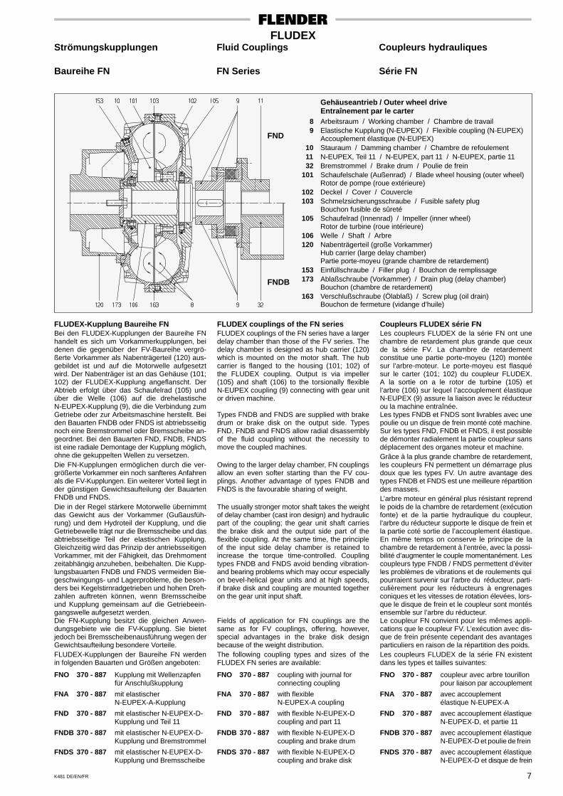
Gehäuseantrieb / Outer wheel driveEntraînement par le carter
8 Arbeitsraum / Working chamber / Chambre de travail 9 Elastische Kupplung (N-EUPEX) / Flexible coupling (N-EUPEX)
Accouplement élastique (N-EUPEX) 10 Stauraum / Damming chamber / Chambre de refoulement 11 N-EUPEX, Teil 11 / N-EUPEX, part 11 / N-EUPEX, partie 11 32 Bremstrommel / Brake drum / Poulie de frein101 Schaufelschale (Außenrad) / Blade wheel housing (outer wheel)
Rotor de pompe (roue extérieure)102 Deckel / Cover / Couvercle103 Schmelzsicherungsschraube / Fusible safety plug
Bouchon fusible de sûreté105 Schaufelrad (Innenrad) / Impeller (inner wheel)
Rotor de turbine (roue intérieure)106 Welle / Shaft / Arbre120 Nabenträgerteil (große Vorkammer)
Hub carrier (large delay chamber)Partie porte-moyeu (grande chambre de retardement)
153 Einfüllschraube / Filler plug / Bouchon de remplissage173 Ablaßschraube (Vorkammer) / Drain plug (delay chamber)
Bouchon (chambre de retardement)163 Verschlußschraube (Ölablaß) / Screw plug (oil drain)
Bouchon de fermeture (vidange d’huile)
FND
FNDB
FLUDEX-Kupplung Baureihe FNBei den FLUDEX-Kupplungen der Baureihe FNhandelt es sich um Vorkammerkupplungen, beidenen die gegenüber der FV-Baureihe vergrö-ßerte Vorkammer als Nabenträgerteil (120) aus-gebildet ist und auf die Motorwelle aufgesetztwird. Der Nabenträger ist an das Gehäuse (101;102) der FLUDEX-Kupplung angeflanscht. DerAbtrieb erfolgt über das Schaufelrad (105) undüber die Welle (106) auf die drehelastischeN-EUPEX-Kupplung (9), die die Verbindung zumGetriebe oder zur Arbeitsmaschine herstellt. Beiden Bauarten FNDB oder FNDS ist abtriebsseitignoch eine Bremstrommel oder Bremsscheibe an-geordnet. Bei den Bauarten FND, FNDB, FNDSist eine radiale Demontage der Kupplung möglich,ohne die gekuppelten Wellen zu versetzen.Die FN-Kupplungen ermöglichen durch die ver-größerte Vorkammer ein noch sanfteres Anfahrenals die FV-Kupplungen. Ein weiterer Vorteil liegt inder günstigen Gewichtsaufteilung der BauartenFNDB und FNDS.Die in der Regel stärkere Motorwelle übernimmtdas Gewicht aus der Vorkammer (Gußausfüh-rung) und dem Hydroteil der Kupplung, und dieGetriebewelle trägt nur die Bremsscheibe und dasabtriebsseitige Teil der elastischen Kupplung.Gleichzeitig wird das Prinzip der antriebsseitigenVorkammer, mit der Fähigkeit, das Drehmomentzeitabhängig anzuheben, beibehalten. Die Kupp-lungsbauarten FNDB und FNDS vermeiden Bie-geschwingungs- und Lagerprobleme, die beson-ders bei Kegelstirnradgetrieben und hohen Dreh-zahlen auftreten können, wenn Bremsscheibeund Kupplung gemeinsam auf die Getriebeein-gangswelle aufgesetzt werden.Die FN-Kupplung besitzt die gleichen Anwen-dungsgebiete wie die FV-Kupplung. Sie bietetjedoch bei Bremsscheibenausführung wegen derGewichtsaufteilung besondere Vorteile.FLUDEX-Kupplungen der Baureihe FN werdenin folgenden Bauarten und Größen angeboten:
FNO 370 - 887 Kupplung mit Wellenzapfenfür Anschlußkupplung
FNA 370 - 887 mit elastischerN-EUPEX-A-Kupplung
FND 370 - 887 mit elastischer N-EUPEX-D-Kupplung und Teil 11
FNDB 370 - 887 mit elastischer N-EUPEX-D-Kupplung und Bremstrommel
FNDS 370 - 887 mit elastischer N-EUPEX-D-Kupplung und Bremsscheibe
FLUDEX couplings of the FN seriesFLUDEX couplings of the FN series have a largerdelay chamber than those of the FV series. Thedelay chamber is designed as hub carrier (120)which is mounted on the motor shaft. The hubcarrier is flanged to the housing (101; 102) ofthe FLUDEX coupling. Output is via impeller(105) and shaft (106) to the torsionally flexibleN-EUPEX coupling (9) connecting with gear unitor driven machine.
Types FNDB and FNDS are supplied with brakedrum or brake disk on the output side. TypesFND, FNDB and FNDS allow radial disassemblyof the fluid coupling without the necessity tomove the coupled machines.
Owing to the larger delay chamber, FN couplingsallow an even softer starting than the FV cou-plings. Another advantage of types FNDB andFNDS is the favourable sharing of weight.
The usually stronger motor shaft takes the weightof delay chamber (cast iron design) and hydraulicpart of the coupling; the gear unit shaft carriesthe brake disk and the output side part of theflexible coupling. At the same time, the principleof the input side delay chamber is retained toincrease the torque time-controlled. Couplingtypes FNDB and FNDS avoid bending vibration-and bearing problems which may occur especiallyon bevel-helical gear units and at high speeds,if brake disk and coupling are mounted togetheron the gear unit input shaft.
Fields of application for FN couplings are thesame as for FV couplings, offering, however,special advantages in the brake disk designbecause of the weight distribution.The following coupling types and sizes of theFLUDEX FN series are available:
FNO 370 - 887 coupling with journal forconnecting coupling
FNA 370 - 887 with flexibleN-EUPEX-A coupling
FND 370 - 887 with flexible N-EUPEX-Dcoupling and part 11
FNDB 370 - 887 with flexible N-EUPEX-Dcoupling and brake drum
FNDS 370 - 887 with flexible N-EUPEX-Dcoupling and brake disk
Coupleurs FLUDEX série FNLes coupleurs FLUDEX de la série FN ont unechambre de retardement plus grande que ceuxde la série FV. La chambre de retardementconstitue une partie porte-moyeu (120) montéesur l’arbre-moteur. Le porte-moyeu est flasquésur le carter (101; 102) du coupleur FLUDEX.A la sortie on a le rotor de turbine (105) etl’arbre (106) sur lequel l’accouplement élastiqueN-EUPEX (9) assure la liaison avec le réducteurou la machine entraînée.Les types FNDB et FNDS sont livrables avec unepoulie ou un disque de frein monté coté machine.Sur les types FND, FNDB et FNDS, il est possiblede démonter radialement la partie coupleur sansdéplacement des organes moteur et machine.Grâce à la plus grande chambre de retardement,les coupleurs FN permettent un démarrage plusdoux que les types FV. Un autre avantage destypes FNDB et FNDS est une meilleure répartitiondes masses.L’arbre moteur en général plus résistant reprendle poids de la chambre de retardement (exécutionfonte) et de la partie hydraulique du coupleur,l’arbre du réducteur supporte le disque de frein etla partie coté sortie de l’accouplement élastique.En même temps on conserve le principe de lachambre de retardement à l’entrée, avec la possi-bilité d’augmenter le couple momentanément. Lescoupleurs type FNDB / FNDS permettent d’éviterles problèmes de vibrations et de roulements quipourraient survenir sur l’arbre du réducteur, parti-culièrement pour les réducteurs à engrenagesconiques et les vitesses de rotation élevées, lors-que le disque de frein et le coupleur sont montésensemble sur l’arbre du réducteur.Le coupleur FN convient pour les mêmes appli-cations que le coupleur FV. L’exécution avec dis-que de frein présente cependant des avantagesparticuliers en raison de la répartition des poids.Les coupleurs FLUDEX de la série FN existentdans les types et tailles suivantes:
FNO 370 - 887 coupleur avec arbre tourillonpour liaison par accouplement
FNA 370 - 887 avec accouplementélastique N-EUPEX-A
FND 370 - 887 avec accouplement élastiqueN-EUPEX-D, et partie 11
FNDB 370 - 887 avec accouplement élastiqueN-EUPEX-D et poulie de frein
FNDS 370 - 887 avec accouplement élastiqueN-EUPEX-D et disque de frein
K481 DE/EN/FR8
FLUDEXStrömungskupplungen Fluid Couplings Coupleurs hydrauliques
Technische Angaben zur Technical Data for the Données techniques pour le choixAuswahl und Größenbestimmung Selection of Size et la détermination de la taille
Die Auswahl einer geeigneten Bauart und die Be-stimmung der jeweils günstigsten Größe ist immerdann zuverlässig möglich, wenn die Belastungs-verhältnisse und Umgebungseinflüsse, denen dieFLUDEX-Strömungskupplung später im Betriebausgesetzt sein wird, entsprechend berücksich-tigt werden.Wir bitten zur Vermeidung von Irrtümern und zeit-raubenden Rückfragen, bei der Bestellung nach-stehende Angaben zu berücksichtigen.
1. Verwendungszweck der FLUDEX-Strömungskupplung
1.1 Als Anlaufhilfe1.2 Für Überlastschutz1.3 Zur Schwingungstrennung oder Stoßdämp-
fung.
2. Beschreibung der Kraftmaschine2.1 Art der Kraftmaschine2.2 Bei Elektromotor: Angabe ob Direkt- oder
Y-∆ - Einschaltung. Bei Y-∆ - EinschaltungAngabe des Umschaltzeitpunktes und dergeforderten Strombegrenzung. Hierzu müs-sen Motorkennlinien von Kundenseite be-reitgestellt werden.
2.3 Bei Verbrennungsmotor: Angabe der Dreh-zahlen und Drehmomente im Leerlauf- undim Vollastbetrieb, maximal zulässigesSchleppmoment der Kupplung in der Leer-laufdrehzahl (Anlaßdrehzahl).
2.4 Leistung P1 in kW, Betriebsdrehzahl n1 inmin-1.
3. Beschreibung der Arbeitsmaschine3.1 Art der Arbeitsmaschine3.2 Soll-Leistung P2 in kW, Betriebsdrehzahl n2
in min-1.3.3 Maximales Drehmoment T2max in Nm, Ver-
lauf des Lastmomentes T2 über n2 (Last-kennlinie).
3.4 Gewünschte Drehmomentbegrenzung durchdie Kupplung (Anfahren/Blockade).
4. Belastungsverhältnisse der Kraft- undArbeitsmaschine
4.1 Gleich- oder ungleichmäßiger Betrieb4.2 Massenträgheitsmoment J in kgm2 der Ar-
beitsmaschine.4.3 Anläufe je Stunde (Arbeitsspiele, Einschalt-
dauer).4.4 Bei Reversierbetrieb mit Last in beiden Rich-
tungen: Drehrichtungswechsel je Stunde.4.5 Kräfte aus abtriebsseitigen Übertragungs-
elementen (Fremdkupplungen, Gelenkwel-len, usw.).
5. Umgebungsverhältnisse5.1 Temperatur der Umgebungsluft, die zur Küh-
lung der Kupplung zur Verfügung steht. BeiLufttemperaturen unter -20 °C und oberhalb+45 °C ist Rückfrage erforderlich.
5.2 Einfluß von Strahlungswärme und Wärme-leitung über Wellen. Maximaler Temperatur-einfluß auf die Kupplung in °C.
5.3 Bei Einbau in Laternen/Schutzhauben:a) Laterne/Schutzhaube mit guter Belüftung.b) teilweise geschlossene Laterne/Schutz-
haube mit weniger guter Belüftung.c) geschlossene Laterne mit keinem oder
sehr geringem Luftaustausch.d) geschlossene Schutzhaube (Schall-
schutzhaube) mit oder ohne Fremdbe-lüftung.
5.4 Einfluß von sehr stark staubiger und korro-siver Umgebung.
5.5 Schwingungsbelastung der Kupplung durchAntriebs- und/oder Arbeitsmaschine.
6. Anordnung des Antriebes6.1 Lage des Antriebs- (Motor-) Wellenendes
a) Horizontalb) Geneigt, bei Neigungswinkeln bis 20°
Angabe der Motorlage erwünscht (oben/unten).
A reliable selection of the most suitable type anddetermination of the most favourable size is onlypossible if all aspects of the drive, load conditionsand ambient influences the FLUDEX fluidcoupling will be exposed to in service, are corres-pondingly considered.
Please peruse the following technical data; itwill help to eliminate errors and avoid time-consuming queries when ordering.
1. Application of the FLUDEX fluidcoupling
1.1 As starting aid;1.2 For overload protection;1.3 To separate vibrations or damp shocks.
2. Description of prime mover2.1 Type of prime mover2.2 For electric motors: direct-on-line or star-
delta starting. If star-delta starting, pleasestate commutation time and required currentlimitation. To this end, the customer shouldprovide characteristic motor curves.
2.3 For internal combustion engines: statespeeds and torques when idling and at fullload operation, max. permissible drag torqueof the coupling at idling speed (startingspeed).
2.4 Power rating P1 in kW, operating speed n1 inmin-1.
3. Description of the driven machine3.1 Type of driven machine3.2 Nominal power rating P2 in kW, operating
speed n2 in min-1.3.3 Max. torque T2max in Nm, load torque cycle
T2/n2 (characteristic load curve).
3.4 Desired torque limitation by the coupling(starting/stalling).
4. Load conditions of prime mover anddriven machine
4.1 Uniform or shock loads4.2 Mass moments of inertia J in kgm2 of driven
machine.4.3 No. of starts per hour (operating cycles, duty
cycle).4.4 For loaded reversing operation in both
directions: directional changes per hour.4.5 Forces from power transmission elements
acting on output side (other couplings, uni-versal-joint shafts etc.).
5. Ambient conditions5.1 Ambient air temperature available for cool-
ing. For ambient air temperatures below-20 °C and above +45 °C, please refer to us.
5.2 Influence of radiated heat and thermal con-duction via shafts. Max. temperature influ-ence on coupling in °C.
5.3 If fitted into bell housings/guards:a) Bell housing/guard with good ventilation.b) Partly closed bell housing/guard, mode-
rately ventilated.c) Closed bell housing without or with only
very little air exchange.d) Closed guard (sound cover) with or without
separate ventilation.
5.4 Influence of very dusty or corrosive surround-ings.
5.5 Vibratory stresses on coupling through primemover or driven machine.
6. Arrangement of the drive6.1 Position of input (motor) shaft
a) Horizontal;b) Inclined, for angles up to 20°, please state
motor position (motor on top or at thebottom);
Le choix d’un type et la détermination correctede la taille ne peuvent être vraiment sûrs quesi l’on tient compte des conditions de charge etdu milieu environnant auxquels le coupleurhydraulique FLUDEX sera soumis lorsqu’il seraen service.Afin d’éviter les erreurs et les pertes de tempsprovoquées par le manque de renseignements,nous vous prions de nous fournir toutes lesdonnées ci-dessous en cas de commande.
1. Application du coupleurhydraulique FLUDEX
1.1 Auxiliaire de démarrage1.2 Protection contre les surcharges1.3 Filtration des irrégularités cycliques ou amor-
tissement des chocs.
2. Description de la machine motrice2.1 Genre de la machine motrice2.2 Pour les moteurs électriques: enclenche-
ment direct ou étoile-triangle. Pour les en-clenchements Y-tri indiquer le temps de com-mutation et de la limitation de courant re-quise. Le client devra tenir à notre disposition les courbes du moteur.
2.3 Pour les moteurs à combustion: indicationdes vitesses et des couples à vide et encharge, couple de glissement maxi admissi-ble du coupleur à vide (vitesse au démar-rage).
2.4 Puissance P1 en kW, vitesse de service n1en min-1.
3. Description de la machine entraînée3.1 Genre de la machine3.2 Puissance nécessaire P2 en kW, vitesse de
service n2 en min-1.3.3 Couple max. T2max en Nm, cycle du couple
en charge T2/n2 (courbe en charge).
3.4 Limitation souhaitée du couple par le cou-pleur (démarrage/blocage).
4. Conditions de travail des machinesmotrice et entraînée
4.1 Marche régulière ou irrégulière4.2 Moments d’inertie J en kgm2 de la machine
entraînée.4.3 Nombre de démarrages/heure (cycle de
travail, durée).4.4 Pour les services à inversion du sens de rota-
tion sous charge: nombre d’inversion à l’heure.4.5 Forces provenant d’éléments de transmis-
sion côté sortie (accouplements extérieurs,cardans etc.).
5. Conditions ambiantes5.1 Température ambiante dont on dispose pour
le refroidissement du coupleur. Pour destempératures ambiantes inférieures à -20 °Cou supérieures à +45 °C, nous consulter.
5.2 Influence de la chaleur par radiations et con-duction de la chaleur par les arbres. Influencemaximale de la température sur le coupleuren °C.
5.3 En cas de montage dans des lanternes/capots:a) lanterne/capot avec bonne aération.b) lanterne/capot partiellement fermés avec
aération médiocre.c) lanterne fermée avec circulation d’air
nulle ou minime.d) capot fermé (protection antibruit) avec ou
sans aération extérieure.5.4 Influence d’une ambiance très poussièreuse
et corrosive.5.5 Vibrations du coupleur dues à la machine
motrice ou à la machine entraînée.
6. Disposition de l’installation6.1 Position de l’arbre d’entrée (moteur)
a) Horizontalb) Incliné, pour un angle d’inclinaison
jusqu’à 20° indication de la position sou-haitée du moteur (en haut/en bas).
K481 DE/EN/FR 9
FLUDEXStrömungskupplungen Fluid Couplings Coupleurs hydrauliques
Technische Angaben zur Technical Data for the Données techniques pour le choixAuswahl und Größenbestimmung Selection of Size et la détermination de la taille
c) Vertikal oder bei Neigungswinkeln > 205,Angabe der Motorlage erforderlich (Motoroben/Motor unten). Bei Kupplungen mitVorkammer muß die Vorkammer untenliegen.
6.2 Antriebsrichtung der Kupplunga) Antrieb über Innenrad (Schaufelrad),
bevorzugte Antriebsrichtung der Bauar-ten FA..
b) Antrieb über Gehäuse (Schaufelschale),bevorzugte Antriebsrichtung der Bauar-ten FG.., FV.. und FN..
6.3 Bei Riemenscheibenkupplungen der BauartFAR, die nicht auf der Motorwelle aufgesetztsind, ist die Angabe der Drehzahl n2 erfor-derlich (Übersetzung des vorgeschaltetenRiementriebes).
7. SonderanforderungenVom Standard abweichende Sonderanforder-ungen bezüglich der technischen Ausführung:a) Bohrungstoleranzb) Paßfedernutc) Wuchtqualitätd) Axiale Befestigung der Hohlwelle/Nabe
8. Bestimmung der Kupplungsbauart undGröße
8.1 FLUDEX-Kupplungen, die als Anlaufhilfe fürden Motor eingesetzt werden sollen, könnengemäß Zuordnungstabellen Seite 12 (für n1 =1500 min-1) bzw. Seite 13 (für n1 = 3000min-1) ausgewählt werden.
8.2 Die Bestimmung der Kupplungsgröße erfolgtnach der Effektivleistung der Arbeitsmaschi-ne an Hand der drehzahlabhängigen Nenn-leistung, die in den Tafeln 10.I und 10.II ange-geben sind. Die Auswahl der Bauart richtetsich nach der gewünschten Antriebsrichtung(Innenrad/Gehäuse), der konstruktiven Aus-führung und der Drehmomentbegrenzungbeim Anfahren. Bei besonders geringerÜberlastforderung beim Anfahren sind Vor-kammerkupplungen im Regelfall zu bevorzu-gen. Bei Kupplungen in Bremsscheibenaus-führung ist die Gewichtsaufteilung auf Motor-und Arbeitsmaschinenwelle (Getriebe) zubeachten. Hier bietet sich die Bauart FNDBals günstige Lösung einer Vorkammerkupp-lung an.
8.3 Die in den Tafeln angegebenen Leistungenbedingen in der Regel die maximal zulässigeFüllung (80 - 85%) der Kupplung. Wird einsehr niedriges Überlastverhalten gewünscht,so ist besonders bei Kupplungen ohne Vor-kammer eine Teilfüllung erforderlich, wo-durch die in den Tafeln angegebenen Lei-stungen nicht voll ausgenützt werden kön-nen und unter Umständen die nächstgrößereKupplung zu wählen ist. Gegebenenfallsbitten wir um Rückfrage.
9. Nachprüfung auf ErwärmungDie Strömungskupplung erwärmt sich infolge desSchlupfes, der sich in Abhängigkeit von der über-tragenen Leistung, der Drehzahl und der Ölfüllungeinstellt. Die Kupplungs-Nennleistungen in denTafeln 10.I und 10.II basieren auf einem Nenn-schlupf von etwa 3 - 5% (je nach Baugröße) undeiner Kupplungserwärmung von maximal 50 5C.Eine Nachprüfung auf Erwärmung und Rückfragemit möglichst ausführlichen “ Technischen Anga-ben” ist erforderlich, wenn:a) die Umgebungslufttemperatur +45 5C über-
steigt,b) mehr als 6 Anläufe je Stunde auftreten,c) große Massen beschleunigt werden müssen
und die Anlaufzeit bei n1 < 1770 min-1 30 Sek.übersteigt und bei n1 > 1770 min-1 die Anlauf-zeit 15 Sek. übersteigt,
d) eine gute Belüftung der Kupplung nichtgewährleistet ist.
c) Vertical, or for angles > 205, please statemotor position (motor on top or at thebottom). For couplings with delay cham-ber, the delay chamber must be at thebottom.
6.2 Drive direction of couplinga) Drive (input) via impeller, preferred drive
direction of types FA..
b) Drive (input) via housing (blade wheelhousing), preferred drive direction of typesFG.., FV.. and FN..
6.3 For FAR couplings with pulley which arenot mounted on the motor shaft, details ofspeed n2 must be given (ratio of primaryV-belt drive).
7. Special requirementsSpecial requirements regarding the technicaldesign:a) Bore tolerancesb) Keywayc) Balance qualityd) Axial fastening of hollow shaft/hub
8. Determination of coupling type andsize
8.1 FLUDEX couplings to be used as startingaid for the motor can be selected accordingto the tables of assignment on page 12(for n1 = 1500 min-1) or page 13 (for n1 =3000 min-1).
8.2 The coupling size is determined accordingto the effective power rating of the drivenmachine by means of the speed-dependentnominal power ratings listed in tables 10.I and10.II. The type is determined by the desireddirection of rotation (impeller/housing), thedesign and the torque limitation on starting.For particularly low overload requirementson starting, delay chamber couplings shouldbe preferred. Regarding couplings with brakedisks, weight distribution between motor- andmachine shaft must be taken into account.Here, type FNDB offers itself as a favourablesolution of a delay chamber coupling.
8.3 Power ratings listed in tables are, as a rule,based on a max. permissible fluid filling of80 - 85%. In case a very low overload capa-city is desired, partial filling becomes neces-sary especially in couplings without delaychamber. Then, the listed power ratings can-not be fully utilized and the next size couplingmay have to be chosen. Please refer to us,if necessary.
9. Thermal checkThe temperature of the fluid coupling risesdue to slip which occurs subject to the powertransmitted, speed and oil filling. Nominal powerratings listed in tables 10.I and 10.II are basedon a nominal slip of 3 - 5% (dependent on size)and heat generation in the coupling up to 50 5C.A thermal check and reference to us with detail-ed technical data will be necessary:
a) If the ambient temperature exceeds +45 5C;
b) In case of more than 6 starts/h;c) If large masses have to be accelerated and
the starting time exceeds 30 seconds at n1< 1770 min-1 or starting time exceeds 15seconds at n1 > 1770 min-1;
d) If good ventilation of the coupling cannot beguaranteed.
c) Verticale ou avec un angle >205 indicationde la position du moteur indispensable (enhaut/en bas). Dans le cas des coupleursavec chambre de retardement, la cham-bre doit être en bas.
6.2 Sens de l’entraînementa) Entraînement par le rotor de turbine (roue
intérieure), sens d’entraînement privilégiédes types FA..
b) Entraînement par le carter (rotor depompe), sens d’entraînement privilégiédes types FG.., FV.., et FN..
6.3 Dans le cas de coupleurs avec poulie typeFAR qui ne sont pas montés sur l’arbre mo-teur, il est indispensable d’indiquer la vitessede rotation n2 (rapport de l’entraînementprimaire par courroie).
7. Exigences particulièresLes demandes qui s’écartent des exécutionsstandard sur les points suivants:a) Tolérance d’alésageb) Rainure de clavettec) Qualité d’équilibraged) Fixation axiale de l’arbre creux/moyeu
8. Détermination du type et de la tailledu coupleur
8.1 Les coupleurs FLUDEX utilisés en tant quesystème de démarrage doivent être sélec-tionnés à partir du tableau page 12 (pourn1 = 1500 min-1) et du tableau page 13 (pourn1 = 3000 min-1).
8.2 On détermine la taille du coupleur en fonctionde la puissance effective de la machine en-traînée et en corrélation avec les correspon-dances puissance / vitesse indiquées dansles tableaux 10.I et 10.II. Le choix du typese fait en fonction du sens d’entraînementdésiré (rotor de turbine/ carter), de l’exécutionet de la limitation du couple au démarrage.Pour obtenir de très faible surcharge audémarrage, on préfèrera en règle généraleles coupleurs avec chambre de retardement.Dans le cas des coupleurs avec disque defrein tenir compte de la répartition du poidssur l’arbre moteur et sur l’arbre de la machineentraînée (réducteur). Le type FNDB s’avèreêtre ici une solution avantageuse commecoupleur à chambre de retardement.
8.3 Les puissances indiquées dans les tableauxconditionnent en règle générale le remplis-sage admissible maxi. (80 - 85%) du cou-pleur. Si l’on souhaite une capacité de sur-charge très faible, les coupleurs sans cham-bre de retardement plus particulièrementnécessitent un remplissage partiel, ce qui faitqu’on ne peut pas utiliser entièrement lespuissances indiquées dans les tableaux etque l’on est parfois amené à choisir la taillesupérieure. Le cas échéant, nous vous de-mandons de nous consulter.
9. Contrôle de l’échauffementLe coupleur s’échauffe à cause du glissement quise produit en fonction de la puissance transmise,de la vitesse de rotation et de la quantité de fluidehydraulique. Les puissances nominales du coup-leur indiquées dans les tableaux 10.I et 10.II sontbasées sur un glissement nominal de 3 - 5% (se-lon la taille) et un échauffement maxi. de 50 5C. Ilest nécessaire de vérifier l’échauffement et denous consulter avec les données techniquesprécises si possible dans les cas suivantes:a) Température ambiante supérieure à +45 5C,
b) Nombre de démarrage supérieur à 6/heure,c) Lorsque l’on doit accélérer de grandes mas-
ses et que pour n1 < 1770 min-1 le temps dedémarrage dépasse 30 sec. ou pour n1 > 1770min-1 le temps de démarrage dépasse 15 sec.
d) Lorsqu’on ne peut pas garantir une bonneaération du coupleur.
K481 DE/EN/FR10
FLUDEXStrömungskupplungen Fluid Couplings Coupleurs hydrauliques
Nennleistungen Nominal Power Ratings Puissances nominales
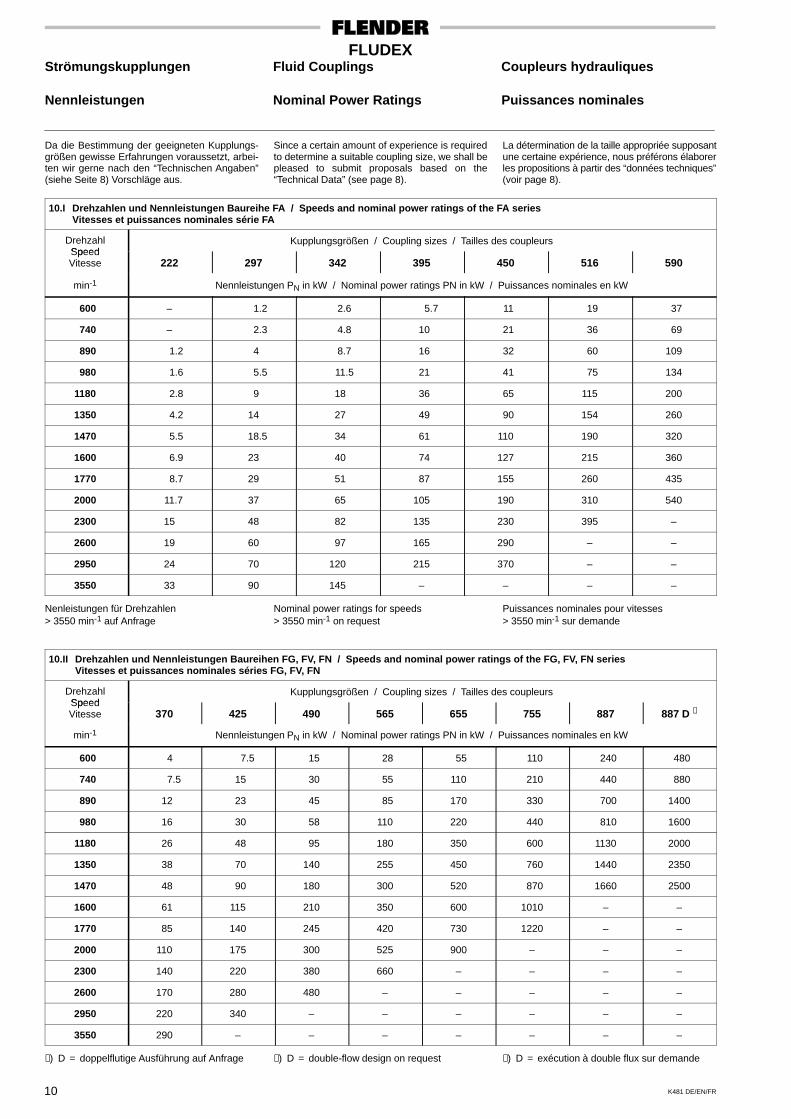
Da die Bestimmung der geeigneten Kupplungs-größen gewisse Erfahrungen voraussetzt, arbei-ten wir gerne nach den “Technischen Angaben”(siehe Seite 8) Vorschläge aus.
Since a certain amount of experience is requiredto determine a suitable coupling size, we shall bepleased to submit proposals based on the“Technical Data” (see page 8).
La détermination de la taille appropriée supposantune certaine expérience, nous préférons élaborerles propositions à partir des “données techniques”(voir page 8).
10.I Drehzahlen und Nennleistungen Baureihe FA / Speeds and nominal power ratings of the FA seriesVitesses et puissances nominales série FA
DrehzahlSpeed
Kupplungsgrößen / Coupling sizes / Tailles des coupleursSpeedVitesse 222 297 342 395 450 516 590
min-1 Nennleistungen PN in kW / Nominal power ratings PN in kW / Puissances nominales en kW
600 – 1.2 2.6 5.7 11 19 37
740 – 2.3 4.8 10 21 36 69
890 1.2 4 8.7 16 32 60 109
980 1.6 5.5 11.5 21 41 75 134
1180 2.8 9 18 36 65 115 200
1350 4.2 14 27 49 90 154 260
1470 5.5 18.5 34 61 110 190 320
1600 6.9 23 40 74 127 215 360
1770 8.7 29 51 87 155 260 435
2000 11.7 37 65 105 190 310 540
2300 15 48 82 135 230 395 –
2600 19 60 97 165 290 – –
2950 24 70 120 215 370 – –
3550 33 90 145 – – – –
Nenleistungen für Drehzahlen> 3550 min-1 auf Anfrage
Nominal power ratings for speeds> 3550 min-1 on request
Puissances nominales pour vitesses> 3550 min-1 sur demande
10.II Drehzahlen und Nennleistungen Baureihen FG, FV, FN / Speeds and nominal power ratings of the FG, FV, FN seriesVitesses et puissances nominales séries FG, FV, FN
DrehzahlSpeed
Kupplungsgrößen / Coupling sizes / Tailles des coupleursSpeedVitesse 370 425 490 565 655 755 887 887 D ∗
min-1 Nennleistungen PN in kW / Nominal power ratings PN in kW / Puissances nominales en kW
600 4 7.5 15 28 55 110 240 480
740 7.5 15 30 55 110 210 440 880
890 12 23 45 85 170 330 700 1400
980 16 30 58 110 220 440 810 1600
1180 26 48 95 180 350 600 1130 2000
1350 38 70 140 255 450 760 1440 2350
1470 48 90 180 300 520 870 1660 2500
1600 61 115 210 350 600 1010 – –
1770 85 140 245 420 730 1220 – –
2000 110 175 300 525 900 – – –
2300 140 220 380 660 – – – –
2600 170 280 480 – – – – –
2950 220 340 – – – – – –
3550 290 – – – – – – –
∗) D = doppelflutige Ausführung auf Anfrage ∗) D = double-flow design on request ∗) D = exécution à double flux sur demande
K481 DE/EN/FR 11
FLUDEXStrömungskupplungen Fluid Couplings Coupleurs hydrauliquesKennlinienbeispiele Examples of Characteristic Exemples de courbes
Curves caractéristiquesExplosionsschutz Explosion Protection Atmosphères explosives
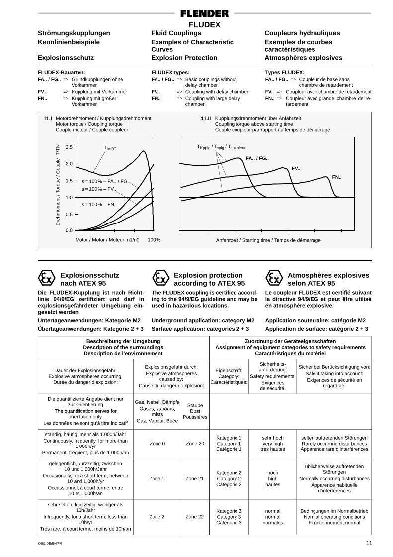
FLUDEX-Bauarten:FA.. / FG.. => Grundkupplungen ohne
VorkammerFV.. => Kupplung mit VorkammerFN.. => Kupplung mit großer
Vorkammer
FLUDEX types:FA.. / FG.. => Basic couplings without
delay chamberFV.. => Coupling with delay chamberFN.. => Coupling with large delay
chamber
Types FLUDEX:FA.. / FG.. => Coupleur de base sans
chambre de retardementFV.. => Coupleur avec chambre de retardementFN.. => Coupleur avec grande chambre de re-
tardement
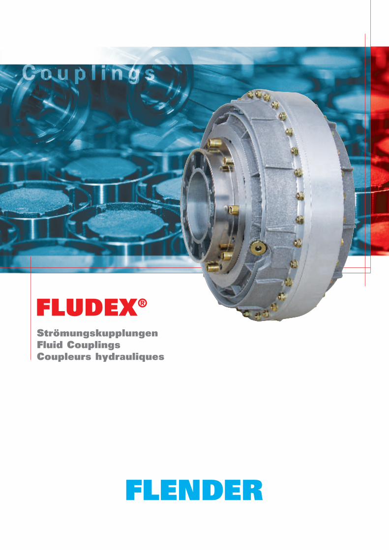
11.I 11.IIMotordrehmoment / KupplungsdrehmomentMotor torque / Coupling torqueCouple moteur / Couple coupleur
Dre
hmom
ent /
Tor
que
/ Cou
ple
T/T
N
Kupplungsdrehmoment über AnfahrzeitCoupling torque above starting timeCouple coupleur par rapport au temps de démarrage
Anfahrzeit / Starting time / Temps de démarrage
0.0
Motor / Motor / Moteur n1/n0 100%
0.5
1.0
1.5
2.0
2.5
s = 100% – FN..
s = 100% – FV..
s = 100% – FA.. / FG..
TMOT TKpplg / Tcplg / Tcoupleur
FA.. / FG..
FV..
FN..
Explosionsschutznach ATEX 95
Die FLUDEX-Kupplung ist nach Richt-linie 94/9/EG zertifiziert und darf inexplosionsgefährdeter Umgebung ein-gesetzt werden.Untertageanwendungen: Kategorie M2Übertageanwendungen: Kategorie 2 + 3
Explosion protectionaccording to ATEX 95
The FLUDEX coupling is certified accord-ing to the 94/9/EG guideline and may beused in hazardous locations.
Underground application: category M2Surface application: categories 2 + 3
Atmosphères explosivesselon ATEX 95
Le coupleur FLUDEX est certifié suivantla directive 94/9/EG et peut être utiliséen atmosphère explosive.
Application souterraine: catégorie M2Application de surface: catégorie 2 + 3
Beschreibung der UmgebungDescription of the surroundingsDescription de l’environnement
Zuordnung der GeräteeigenschaftenAssignment of equipment categories to safety requirements
Caractéristiques du matériel
Dauer der Explosionsgefahr:Explosive atmospheres occurring:
Durée du danger d’explosion:
Explosionsgefahr durch:Explosive atmospheres
caused by:Cause du danger d’explosión:
Eigenschaft:Category:
Caractéristiques:
Sicherheits-anforderung:
Safety requirements:Exigences
de sécurité:
Sicher bei Berücksichtigung von:Safe if taking into account:Exigences de sécurité en
regard de:
Die quantifizierte Angabe dient nurzur Orientierung
The quantification serves for
Gas, Nebel, DämpfeGases, vapours,
StäubeDustThe quantification serves for
orientation only.Les données ne sont qu’à titre indicatif
Gases, va ours,mists
Gaz, Vapeur, Buée
DustPoussières
ständig, häufig, mehr als 1.000h/JahrContinuously, frequently, for more than
1,000h/yrPermanent, fréquent, plus de 1.000h/an
Zone 0 Zone 20Kategorie 1Category 1Catégorie 1
sehr hochvery high
très hautes
selten auftretenden StörungenRarely occurring disturbancesApparence rare d’interférences
gelegentlich, kurzzeitig, zwischen10 und 1.000h/Jahr
Occasionally, for a short term, between10 and 1,000h/yr
Occassionnel, à court terme, entre10 et 1.000h/an
Zone 1 Zone 21Kategorie 2Category 2Catégorie 2
hochhigh
hautes
üblicherweise auftretendenStörungen
Normally occurring disturbancesApparence habituelle
d’interférences
sehr selten, kurzzeitig, weniger als10h/Jahr
Infrequently, for a short term, less than10h/yr
Très rare, à court terme, moins de 10h/an
Zone 2 Zone 22Kategorie 3Category 3Catégorie 3
normalnormal
normales
Bedingungen im NormalbetriebNormal operating conditions
Fonctionnement normal
K481 DE/EN/FR12
FLUDEXStrömungskupplungen Fluid Couplings Coupleurs hydrauliquesals Anlaufhilfe für as Starting Aid for comme auxiliaire de démarrageIEC-Motoren IEC Motors pour moteurs selon normes IEC� � ���� ����� � � ���� ����� � � ���� �����
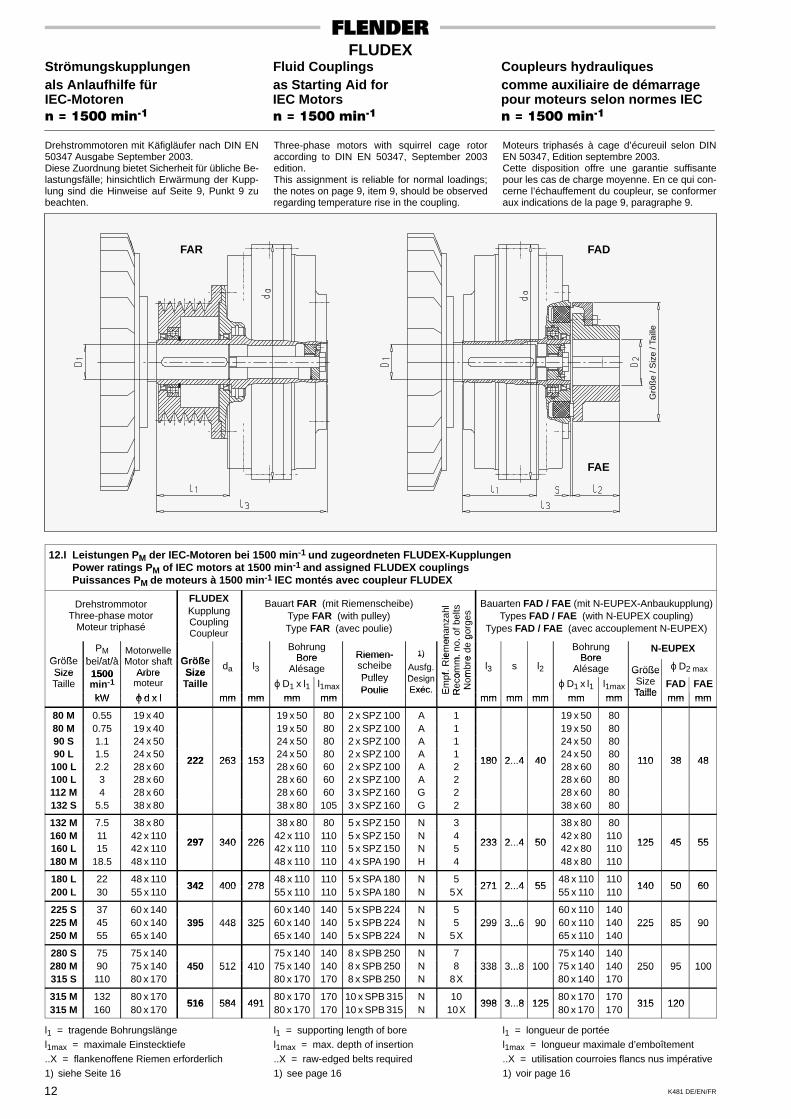
Drehstrommotoren mit Käfigläufer nach DIN EN50347 Ausgabe September 2003.Diese Zuordnung bietet Sicherheit für übliche Be-lastungsfälle; hinsichtlich Erwärmung der Kupp-lung sind die Hinweise auf Seite 9, Punkt 9 zubeachten.
Three-phase motors with squirrel cage rotoraccording to DIN EN 50347, September 2003edition.This assignment is reliable for normal loadings;the notes on page 9, item 9, should be observedregarding temperature rise in the coupling.
Moteurs triphasés à cage d’écureuil selon DINEN 50347, Edition septembre 2003.Cette disposition offre une garantie suffisantepour les cas de charge moyenne. En ce qui con-cerne l’échauffement du coupleur, se conformeraux indications de la page 9, paragraphe 9.
FAR FAD
FAE
Grö
ße
/ Siz
e / T
aille
12.I Leistungen PM der IEC-Motoren bei 1500 min-1 und zugeordneten FLUDEX-KupplungenPower ratings PM of IEC motors at 1500 min-1 and assigned FLUDEX couplingsPuissances PM de moteurs à 1500 min-1 IEC montés avec coupleur FLUDEX
DrehstrommotorThree-phase motor
Moteur triphasé
FLUDEXKupplungCouplingCoupleur
Bauart FAR (mit Riemenscheibe)Type FAR (with pulley)Type FAR (avec poulie)
enan
zahl
o. o
f bel
tsgo
rges
Bauarten FAD / FAE (mit N-EUPEX-Anbaukupplung)Types FAD / FAE (with N-EUPEX coupling)
Types FAD / FAE (avec accouplement N-EUPEX)
GrößePM
bei/at/àMotorwelleM t h ft Größe
BohrungBore Riemen- 1) ie
men
m. n
o.
e de
g
BohrungBore
N-EUPEXGrößeSize
bei/at/à1500
Motor shaftArbre
GrößeSize
da l3Bore
AlésageRiemen-scheibePulley
1)
Ausfg.Design
f. R
ieom
m.
mbr
e
l3 s l2Bore
Alésage GrößeS
ϕ D2 maxSizeTaille
1500min-1
Arbremoteur
SizeTaille ϕ D1 x l1 l1max
PulleyPoulie
DesignExéc. E
mpf
Rec
oN
om ϕ D1 x l1 l1max
GrößeSizeTaille
FAD FAEkW ϕ d x l mm mm mm mm
Poulie Exéc. E Re N
mm mm mm mm mm Taille mm mmkW ϕ d x l mm mm mm mm
R
mm mm mm mm mm Taille mm mm
80 M 0.55 19 x 40 19 x 50 80 2 x SPZ 100 A 1 19 x 50 8080 M 0.75 19 x 40 19 x 50 80 2 x SPZ 100 A 1 19 x 50 8090 S 1.1 24 x 50 24 x 50 80 2 x SPZ 100 A 1 24 x 50 8090 L 1.5 24 x 50
222 263 15324 x 50 80 2 x SPZ 100 A 1
180 2 4 4024 x 50 80
110 38 48100 L 2.2 28 x 60
222 263 15328 x 60 60 2 x SPZ 100 A 2
180 2...4 4028 x 60 80
110 38 48
100 L 3 28 x 60 28 x 60 60 2 x SPZ 100 A 2 28 x 60 80112 M 4 28 x 60 28 x 60 60 3 x SPZ 160 G 2 28 x 60 80132 S 5.5 38 x 80 38 x 80 105 3 x SPZ 160 G 2 38 x 60 80
132 M 7.5 38 x 80 38 x 80 80 5 x SPZ 150 N 3 38 x 80 80160 M 11 42 x 110
297 340 22642 x 110 110 5 x SPZ 150 N 4
233 2 4 5042 x 80 110
125 45 55160 L 15 42 x 110
297 340 22642 x 110 110 5 x SPZ 150 N 5
233 2...4 5042 x 80 110
125 45 55
180 M 18.5 48 x 110 48 x 110 110 4 x SPA 190 H 4 48 x 80 110
180 L 22 48 x 110342 400 278
48 x 110 110 5 x SPA 180 N 5271 2 4 55
48 x 110 110140 50 60
200 L 30 55 x 110342 400 278
55 x 110 110 5 x SPA 180 N 5X271 2...4 55
55 x 110 110140 50 60
225 S 37 60 x 140 60 x 140 140 5 x SPB 224 N 5 60 x 110 140225 M 45 60 x 140 395 448 325 60 x 140 140 5 x SPB 224 N 5 299 3...6 90 60 x 110 140 225 85 90250 M 55 65 x 140
395 448 32565 x 140 140 5 x SPB 224 N 5X
299 3...6 9065 x 110 140
225 85 90
280 S 75 75 x 140 75 x 140 140 8 x SPB 250 N 7 75 x 140 140280 M 90 75 x 140 450 512 410 75 x 140 140 8 x SPB 250 N 8 338 3...8 100 75 x 140 140 250 95 100315 S 110 80 x 170
450 512 41080 x 170 170 8 x SPB 250 N 8X
338 3...8 10080 x 140 170
250 95 100
315 M 132 80 x 170516 584 491
80 x 170 170 10 x SPB 315 N 10398 3 8 125
80 x 170 170315 120
315 M 160 80 x 170516 584 491
80 x 170 170 10 x SPB 315 N 10X398 3...8 125
80 x 170 170315 120
l1 = tragende Bohrungslängel1max = maximale Einstecktiefe..X = flankenoffene Riemen erforderlich1) siehe Seite 16
l1 = supporting length of borel1max = max. depth of insertion..X = raw-edged belts required1) see page 16
l1 = longueur de portéel1max = longueur maximale d’emboîtement..X = utilisation courroies flancs nus impérative1) voir page 16
K481 DE/EN/FR 13
FLUDEXStrömungskupplungen Fluid Couplings Coupleurs hydrauliquesals Anlaufhilfe für as Starting Aid for comme auxiliaire de démarrageIEC-Motoren IEC Motors pour moteurs selon normes IEC� � ���� ����� � � ���� ����� � � ���� �����
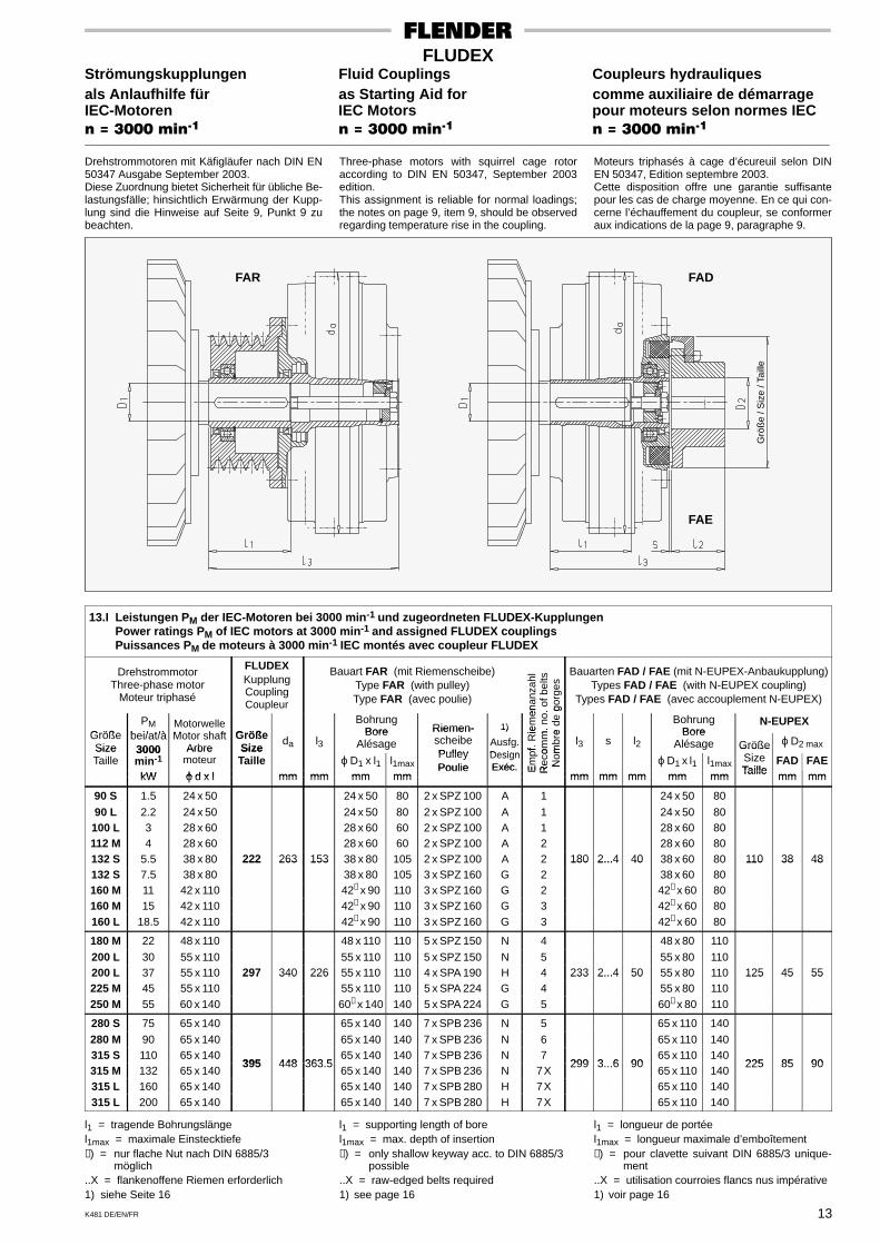
Drehstrommotoren mit Käfigläufer nach DIN EN50347 Ausgabe September 2003.Diese Zuordnung bietet Sicherheit für übliche Be-lastungsfälle; hinsichtlich Erwärmung der Kupp-lung sind die Hinweise auf Seite 9, Punkt 9 zubeachten.
Three-phase motors with squirrel cage rotoraccording to DIN EN 50347, September 2003edition.This assignment is reliable for normal loadings;the notes on page 9, item 9, should be observedregarding temperature rise in the coupling.
Moteurs triphasés à cage d’écureuil selon DINEN 50347, Edition septembre 2003.Cette disposition offre une garantie suffisantepour les cas de charge moyenne. En ce qui con-cerne l’échauffement du coupleur, se conformeraux indications de la page 9, paragraphe 9.
FAR FAD
FAE
Grö
ße
/ Siz
e / T
aille
13.I Leistungen PM der IEC-Motoren bei 3000 min-1 und zugeordneten FLUDEX-KupplungenPower ratings PM of IEC motors at 3000 min-1 and assigned FLUDEX couplingsPuissances PM de moteurs à 3000 min-1 IEC montés avec coupleur FLUDEX
DrehstrommotorThree-phase motor
Moteur triphasé
FLUDEXKupplungCouplingCoupleur
Bauart FAR (mit Riemenscheibe)Type FAR (with pulley)Type FAR (avec poulie)
enan
zahl
o. o
f bel
tsgo
rges
Bauarten FAD / FAE (mit N-EUPEX-Anbaukupplung)Types FAD / FAE (with N-EUPEX coupling)
Types FAD / FAE (avec accouplement N-EUPEX)
GrößePM
bei/at/àMotorwelleM t h ft Größe
BohrungBore Riemen- 1) ie
men
m. n
o.
e de
g
BohrungBore
N-EUPEXGrößeSize
bei/at/à3000
Motor shaftArbre
GrößeSize
da l3Bore
AlésageRiemen-scheibePulley
1)
Ausfg.Design
f. R
ieom
m.
mbr
e
l3 s l2Bore
Alésage GrößeS
ϕ D2 maxSizeTaille
3000min-1
Arbremoteur
SizeTaille ϕ D1 x l1 l1max
PulleyPoulie
DesignExéc. E
mpf
Rec
oN
om ϕ D1 x l1 l1max
GrößeSizeTaille
FAD FAEkW ϕ d x l mm mm mm mm
Poulie Exéc. E Re N
mm mm mm mm mm Taille mm mmkW ϕ d x l mm mm mm mm
R
mm mm mm mm mm Taille mm mm
90 S 1.5 24 x 50 24 x 50 80 2 x SPZ 100 A 1 24 x 50 80
90 L 2.2 24 x 50 24 x 50 80 2 x SPZ 100 A 1 24 x 50 80100 L 3 28 x 60 28 x 60 60 2 x SPZ 100 A 1 28 x 60 80112 M 4 28 x 60 28 x 60 60 2 x SPZ 100 A 2 28 x 60 80132 S 5.5 38 x 80 222 263 153 38 x 80 105 2 x SPZ 100 A 2 180 2...4 40 38 x 60 80 110 38 48132 S 7.5 38 x 80
222 263 15338 x 80 105 3 x SPZ 160 G 2
180 2...4 4038 x 60 80
110 38 48
160 M 11 42 x 110 42∗ x 90 110 3 x SPZ 160 G 2 42∗ x 60 80160 M 15 42 x 110 42∗ x 90 110 3 x SPZ 160 G 3 42∗ x 60 80160 L 18.5 42 x 110 42∗ x 90 110 3 x SPZ 160 G 3 42∗ x 60 80
180 M 22 48 x 110 48 x 110 110 5 x SPZ 150 N 4 48 x 80 110
200 L 30 55 x 110 55 x 110 110 5 x SPZ 150 N 5 55 x 80 110200 L 37 55 x 110 297 340 226 55 x 110 110 4 x SPA 190 H 4 233 2...4 50 55 x 80 110 125 45 55225 M 45 55 x 110
297 340 22655 x 110 110 5 x SPA 224 G 4
233 2...4 5055 x 80 110
125 45 55
250 M 55 60 x 140 60∗ x 140 140 5 x SPA 224 G 5 60∗ x 80 110
280 S 75 65 x 140 65 x 140 140 7 x SPB 236 N 5 65 x 110 140
280 M 90 65 x 140 65 x 140 140 7 x SPB 236 N 6 65 x 110 140315 S 110 65 x 140
395 448 363 565 x 140 140 7 x SPB 236 N 7
299 3 6 9065 x 110 140
225 85 90315 M 132 65 x 140
395 448 363.565 x 140 140 7 x SPB 236 N 7X
299 3...6 9065 x 110 140
225 85 90
315 L 160 65 x 140 65 x 140 140 7 x SPB 280 H 7X 65 x 110 140315 L 200 65 x 140 65 x 140 140 7 x SPB 280 H 7X 65 x 110 140
l1 = tragende Bohrungslängel1max = maximale Einstecktiefe∗) = nur flache Nut nach DIN 6885/3
möglich..X = flankenoffene Riemen erforderlich1) siehe Seite 16
l1 = supporting length of borel1max = max. depth of insertion∗) = only shallow keyway acc. to DIN 6885/3
possible..X = raw-edged belts required1) see page 16
l1 = longueur de portéel1max = longueur maximale d’emboîtement∗) = pour clavette suivant DIN 6885/3 unique-
ment..X = utilisation courroies flancs nus impérative1) voir page 16
K481 DE/EN/FR14
FLUDEXStrömungskupplungen Fluid Couplings Coupleurs hydrauliques
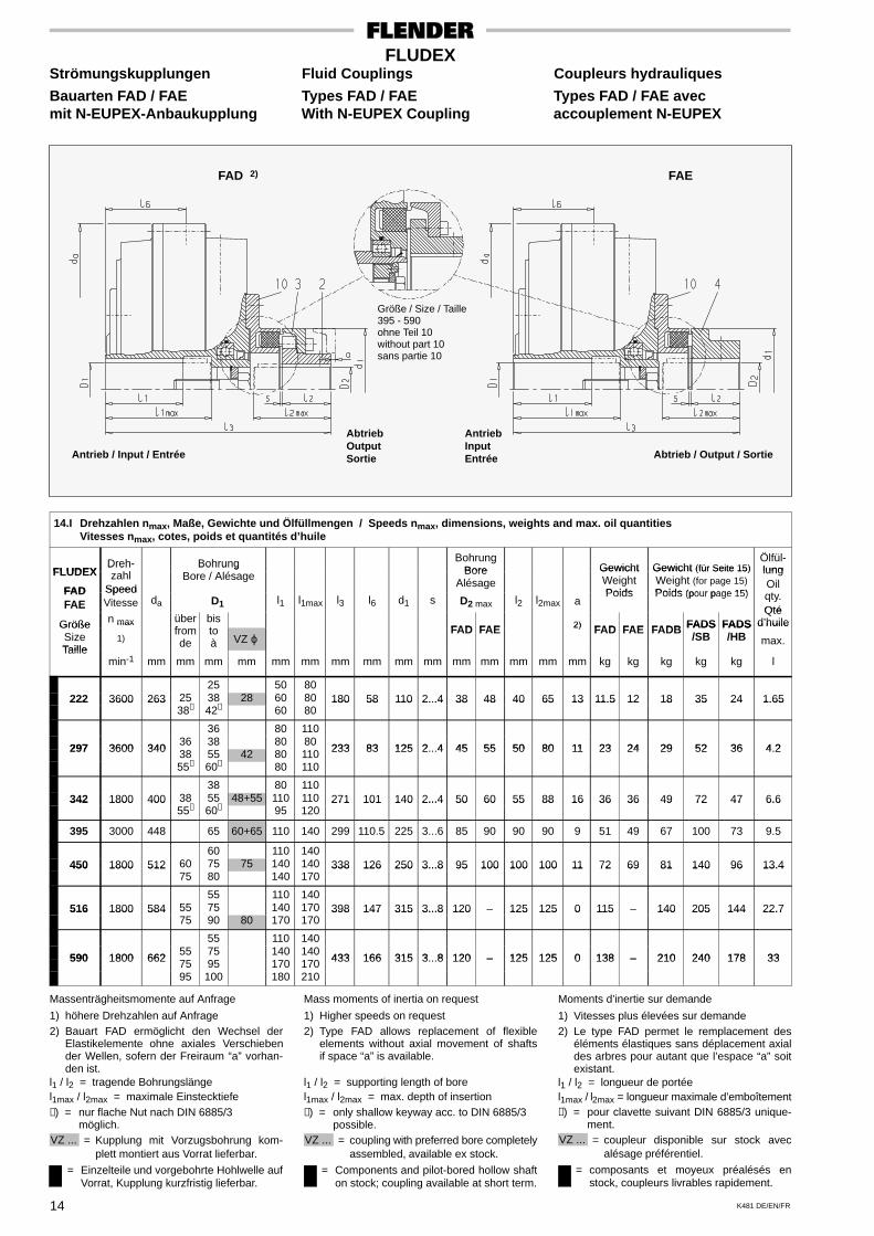
Bauarten FAD / FAE Types FAD / FAE Types FAD / FAE avecmit N-EUPEX-Anbaukupplung With N-EUPEX Coupling accouplement N-EUPEX
FAD 2)
Antrieb / Input / Entrée
FAE
AbtriebOutputSortie
Größe / Size / Taille395 - 590ohne Teil 10without part 10sans partie 10
AntriebInputEntrée Abtrieb / Output / Sortie
14.I Drehzahlen nmax, Maße, Gewichte und Ölfüllmengen / Speeds nmax, dimensions, weights and max. oil quantitiesVitesses nmax, cotes, poids et quantités d’huile
FLUDEXDreh-
hlBohrung Bohrung
Bore Gewicht Gewicht (für Seite 15)Ölfül-lungFLUDEX
FAD
Drehzahl
Speed
BohrungBore / Alésage Bore
AlésageGewichtWeightPoids
Gewicht (für Seite 15)Weight (for page 15)Poids (pour page 15)
lungOiltFAD
FAESpeedVitesse da D1 l1 l1max l3 l6 d1 s D2 max l2 l2max a
Poids Poids (pour page 15)Oilqty.QtéFAE
Größe n max überf
bist FAD FAE 2) FAD FAE FADB FADS FADS
Qtéd’huileGröße
SizeTaille
max
1)fromde
toà VZ ϕ
FAD FAE 2) FAD FAE FADB FADS/SB
FADS/HB
d huile
max.Taille
min-1 mm mm mm mm mm mm mm mm mm mm mm mm mm mm mm kg kg kg kg kg l
25 50 80222 3600 263 25 38 28 60 80 180 58 110 2...4 38 48 40 65 13 11.5 12 18 35 24 1.65222 3600 263
38∗ 42∗ 60 80180 58 110 2...4 38 48 40 65 13 11.5 12 18 35 24 1.65
36 80 110
297 3600 34036 38 80 80
233 83 125 2 4 45 55 50 80 11 23 24 29 52 36 4 2297 3600 340 38 55 42 80 110 233 83 125 2...4 45 55 50 80 11 23 24 29 52 36 4.2
55∗ 60∗ 80 110
38 80 110342 1800 400 38 55 48+55 110 110 271 101 140 2...4 50 60 55 88 16 36 36 49 72 47 6.6342 1800 400
55∗ 60∗ 95 120271 101 140 2...4 50 60 55 88 16 36 36 49 72 47 6.6
395 3000 448 65 60+65 110 140 299 110.5 225 3...6 85 90 90 90 9 51 49 67 100 73 9.5
60 110 140450 1800 512 60 75 75 140 140 338 126 250 3...8 95 100 100 100 11 72 69 81 140 96 13.4450 1800 512
75 80 140 170338 126 250 3...8 95 100 100 100 11 72 69 81 140 96 13.4
55 110 140516 1800 584 55 75 140 170 398 147 315 3...8 120 – 125 125 0 115 – 140 205 144 22.7516 1800 584
75 90 80 170 170398 147 315 3...8 120 125 125 0 115 140 205 144 22.7
55 110 140
590 1800 66255 75 140 140
433 166 315 3 8 120 – 125 125 0 138 – 210 240 178 33590 1800 662 75 95 170 170 433 166 315 3...8 120 – 125 125 0 138 – 210 240 178 33
95 100 180 210
Massenträgheitsmomente auf Anfrage
1) höhere Drehzahlen auf Anfrage2) Bauart FAD ermöglicht den Wechsel der
Elastikelemente ohne axiales Verschiebender Wellen, sofern der Freiraum “a” vorhan-den ist.
l1 / l2 = tragende Bohrungslängel1max / l2max = maximale Einstecktiefe∗) = nur flache Nut nach DIN 6885/3
möglich.VZ ... = Kupplung mit Vorzugsbohrung kom-
plett montiert aus Vorrat lieferbar.
= Einzelteile und vorgebohrte Hohlwelle aufVorrat, Kupplung kurzfristig lieferbar.
Mass moments of inertia on request
1) Higher speeds on request2) Type FAD allows replacement of flexible
elements without axial movement of shaftsif space “a” is available.
l1 / l2 = supporting length of borel1max / l2max = max. depth of insertion∗) = only shallow keyway acc. to DIN 6885/3
possible.VZ ... = coupling with preferred bore completely
assembled, available ex stock.
= Components and pilot-bored hollow shafton stock; coupling available at short term.
Moments d’inertie sur demande
1) Vitesses plus élevées sur demande2) Le type FAD permet le remplacement des
éléments élastiques sans déplacement axialdes arbres pour autant que l’espace “a” soitexistant.
l1 / l2 = longueur de portéel1max / l2max = longueur maximale d’emboîtement∗) = pour clavette suivant DIN 6885/3 unique-
ment.VZ ... = coupleur disponible sur stock avec
alésage préférentiel.
= composants et moyeux préalésés enstock, coupleurs livrables rapidement.
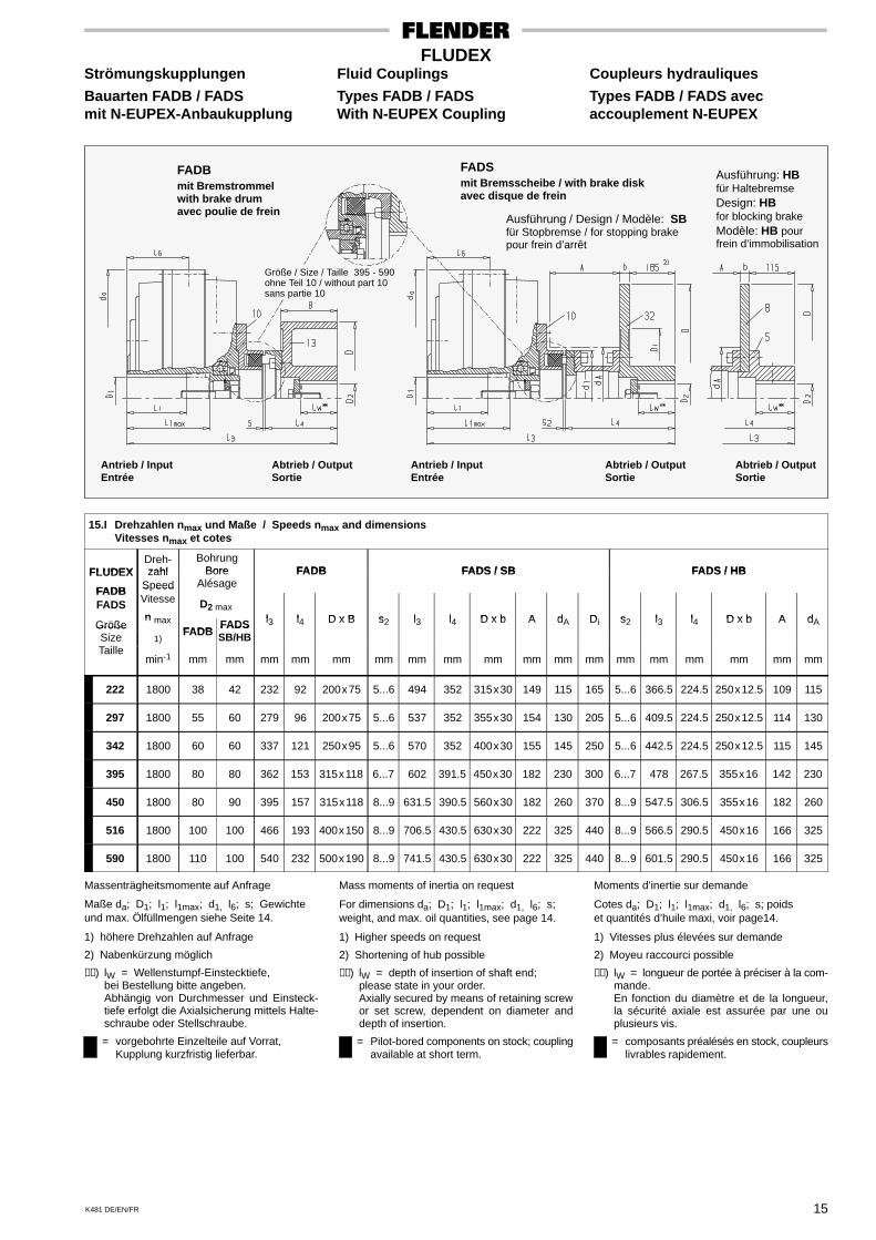
K481 DE/EN/FR 15
FLUDEXStrömungskupplungen Fluid Couplings Coupleurs hydrauliques
Bauarten FADB / FADS Types FADB / FADS Types FADB / FADS avecmit N-EUPEX-Anbaukupplung With N-EUPEX Coupling accouplement N-EUPEX
FADBmit Bremstrommelwith brake drumavec poulie de frein
Antrieb / InputEntrée
FADSmit Bremsscheibe / with brake diskavec disque de frein
Abtrieb / OutputSortie
Größe / Size / Taille 395 - 590ohne Teil 10 / without part 10sans partie 10
Antrieb / InputEntrée
Abtrieb / OutputSortie
Abtrieb / OutputSortie
Ausführung / Design / Modèle: SBfür Stopbremse / for stopping brakepour frein d’arrêt
Ausführung: HBfür HaltebremseDesign: HBfor blocking brakeModèle: HB pourfrein d’immobilisation
15.I Drehzahlen nmax und Maße / Speeds nmax and dimensionsVitesses nmax et cotes
FLUDEXDreh-zahl
BohrungBore FADB FADS / SB FADS / HBFLUDEX
FADB
zahlSpeed
BoreAlésage
FADB FADS / SB FADS / HB
FADBFADS
S eedVitesse
nD2 max
l l D x B s l l D x b A d D s l l D x b A dGrößen max
FADBFADS l3 l4 D x B s2 l3 l4 D x b A dA Di s2 l3 l4 D x b A dAGröße
SizeT ill
1)FADB
FADSSB/HB
Taillemin-1 mm mm mm mm mm mm mm mm mm mm mm mm mm mm mm mm mm mm
222 1800 38 42 232 92 200x75 5...6 494 352 315x30 149 115 165 5...6 366.5 224.5 250x12.5 109 115
297 1800 55 60 279 96 200x75 5...6 537 352 355x30 154 130 205 5...6 409.5 224.5 250x12.5 114 130
342 1800 60 60 337 121 250x95 5...6 570 352 400x30 155 145 250 5...6 442.5 224.5 250x12.5 115 145
395 1800 80 80 362 153 315x118 6...7 602 391.5 450x30 182 230 300 6...7 478 267.5 355x16 142 230
450 1800 80 90 395 157 315x118 8...9 631.5 390.5 560x30 182 260 370 8...9 547.5 306.5 355x16 182 260
516 1800 100 100 466 193 400x150 8...9 706.5 430.5 630x30 222 325 440 8...9 566.5 290.5 450x16 166 325
590 1800 110 100 540 232 500x190 8...9 741.5 430.5 630x30 222 325 440 8...9 601.5 290.5 450x16 166 325
Massenträgheitsmomente auf Anfrage
Maße da; D1; l1; l1max; d1, l6; s; Gewichteund max. Ölfüllmengen siehe Seite 14.
1) höhere Drehzahlen auf Anfrage
2) Nabenkürzung möglich
∗∗) lW = Wellenstumpf-Einstecktiefe,bei Bestellung bitte angeben.Abhängig von Durchmesser und Einsteck-tiefe erfolgt die Axialsicherung mittels Halte-schraube oder Stellschraube.
= vorgebohrte Einzelteile auf Vorrat,Kupplung kurzfristig lieferbar.
Mass moments of inertia on request
For dimensions da; D1; l1; l1max; d1, l6; s;weight, and max. oil quantities, see page 14.
1) Higher speeds on request
2) Shortening of hub possible
∗∗) lW = depth of insertion of shaft end;please state in your order.Axially secured by means of retaining screwor set screw, dependent on diameter anddepth of insertion.
= Pilot-bored components on stock; couplingavailable at short term.
Moments d’inertie sur demande
Cotes da; D1; l1; l1max; d1, l6; s; poidset quantités d’huile maxi, voir page14.
1) Vitesses plus élevées sur demande
2) Moyeu raccourci possible
∗∗) lW = longueur de portée à préciser à la com-mande.En fonction du diamètre et de la longueur,la sécurité axiale est assurée par une ouplusieurs vis.
= composants préalésés en stock, coupleurslivrables rapidement.
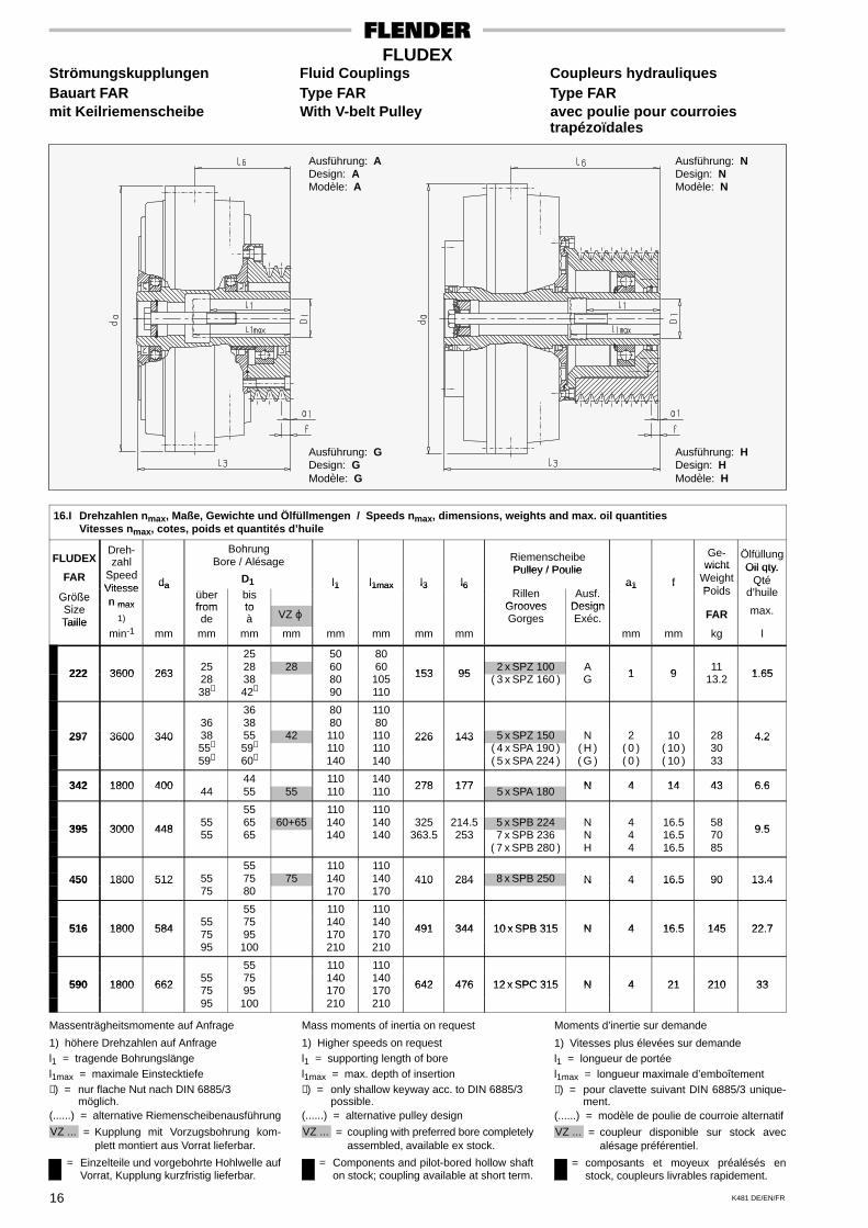
K481 DE/EN/FR16
FLUDEXStrömungskupplungen Fluid Couplings Coupleurs hydrauliquesBauart FAR Type FAR Type FARmit Keilriemenscheibe With V-belt Pulley avec poulie pour courroies
trapézoïdales
Ausführung: ADesign: AModèle: A
Ausführung: GDesign: GModèle: G
Ausführung: NDesign: NModèle: N
Ausführung: HDesign: HModèle: H
16.I Drehzahlen nmax, Maße, Gewichte und Ölfüllmengen / Speeds nmax, dimensions, weights and max. oil quantitiesVitesses nmax, cotes, poids et quantités d’huile
FLUDEXDreh-zahl
S d
BohrungBore / Alésage Riemenscheibe
Pulley / Poulie
Ge-wicht
ÖlfüllungOil qty.
FAR SpeedVitesse da
D1 l1 l1max l3 l6Pulley / Poulie
a1 f
wichtWeightPoids
Oil qty.Qté
d’h ilGrößeSi
Vitessen max
daüberfrom
bisto
l1 l1max l3 l6Rillen
GroovesAusf.
Design
a1 fPoids
Qtéd’huileGröße
SizeTaille
n max
1)fromde
toà VZ ϕ
GroovesGorges
DesignExéc. FAR max.
Taillemin-1 mm mm mm mm mm mm mm mm mm mm kg l
25 50 80
222 3600 26325 28 28 60 60
153 952 x SPZ 100 A
1 911
1 65222 3600 263 28 38 80 105 153 95 ( 3 x SPZ 160 ) G 1 9 13.2 1.65
38∗ 42∗ 90 110
36 80 11036 38 80 80
297 3600 340 38 55 42 110 110 226 143 5 x SPZ 150 N 2 10 28 4.2297 3600 34055∗ 59∗ 110 110
226 143( 4 x SPA 190 ) ( H ) ( 0 ) ( 10 ) 30
4.2
59∗ 60∗ 140 140 ( 5 x SPA 224 ) ( G ) ( 0 ) ( 10 ) 33
342 1800 40044 110 140
278 177 N 4 14 43 6 6342 1800 400 44 55 55 110 110 278 177 5 x SPA 180 N 4 14 43 6.6
55 110 110
395 3000 44855 65 60+65 140 140 325 214.5 5 x SPB 224 N 4 16.5 58
9 5395 3000 448 55 65 140 140 363.5 253 7 x SPB 236 N 4 16.5 70 9.5
( 7 x SPB 280 ) H 4 16.5 85
55 110 110450 1800 512 55 75 75 140 140 410 284 8 x SPB 250 N 4 16.5 90 13.4450 1800 512
75 80 170 170410 284 N 4 16.5 90 13.4
55 110 110
516 1800 58455 75 140 140
491 344 10 x SPB 315 N 4 16 5 145 22 7516 1800 584 75 95 170 170 491 344 10 x SPB 315 N 4 16.5 145 22.7
95 100 210 210
55 110 110
590 1800 66255 75 140 140
642 476 12 x SPC 315 N 4 21 210 33590 1800 662 75 95 170 170 642 476 12 x SPC 315 N 4 21 210 33
95 100 210 210
Massenträgheitsmomente auf Anfrage
1) höhere Drehzahlen auf Anfragel1 = tragende Bohrungslängel1max = maximale Einstecktiefe∗) = nur flache Nut nach DIN 6885/3
möglich.(......) = alternative Riemenscheibenausführung
VZ ... = Kupplung mit Vorzugsbohrung kom-plett montiert aus Vorrat lieferbar.
= Einzelteile und vorgebohrte Hohlwelle aufVorrat, Kupplung kurzfristig lieferbar.
Mass moments of inertia on request
1) Higher speeds on requestl1 = supporting length of borel1max = max. depth of insertion∗) = only shallow keyway acc. to DIN 6885/3
possible.(......) = alternative pulley design
VZ ... = coupling with preferred bore completelyassembled, available ex stock.
= Components and pilot-bored hollow shafton stock; coupling available at short term.
Moments d’inertie sur demande
1) Vitesses plus élevées sur demandel1 = longueur de portéel1max = longueur maximale d’emboîtement∗) = pour clavette suivant DIN 6885/3 unique-
ment.(......) = modèle de poulie de courroie alternatif
VZ ... = coupleur disponible sur stock avecalésage préférentiel.
= composants et moyeux préalésés enstock, coupleurs livrables rapidement.
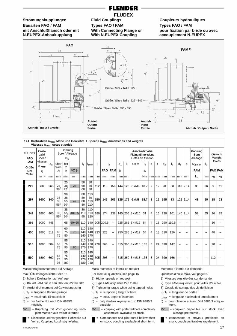
K481 DE/EN/FR 17
FLUDEXStrömungskupplungen Fluid Couplings Coupleurs hydrauliquesBauarten FAO / FAM Types FAO / FAM Types FAO / FAMmit Anschlußflansch oder mit With Connecting Flange or pour fixation par bride ou avecN-EUPEX-Anbaukupplung With N-EUPEX Coupling accouplement N-EUPEX
FAM 2)FAO
AbtriebOutputSortie
AntriebInputEntrée Abtrieb / Output / SortieAntrieb / Input / Entrée
Größe / Size / Taille 222
Größe / Size / Taille 222 - 342
Größe / Size / Taille 395 - 590
17.I Drehzahlen nmax, Maße und Gewichte / Speeds nmax, dimensions and weightsVitesses nmax, cotes et poids
FLUDEXDreh- Bohrung Anschlußmaße Bohrung
FLUDEXDreh-zahl
BohrungBore / Alésage
AnschlußmaßeFitting dimensions
BohrungBore Gewicht
FAOFAM
zahlSpeedVitesse
D1
Fitting dimensionsCotes de fixation
BoreAlésage
GewichtWeightPoidsFAM
Größe
Vitesse
n maxda über
frombisto
l1 l1max l l3 d1 k a x M Ta z t d2 l6 d1 s D2 max l2Poids
GrößeSizeTaille
n max
1)
fromde
toà VZ ϕ FAO FAM j7 3) FAM FAO FAM
Taillemin-1 mm mm mm mm mm mm mm mm mm mm mm Nm mm mm mm mm mm mm kg mm kg kg
25 50 80222 3600 263 25 38 28 60 80 112 110 150 144 128 6xM8 18.7 2 12 90 58 110 2...4 38 36 9 11222 3600 263
38∗ 42∗ 60 80112 110 150 144 128 6xM8 18.7 2 12 90 58 110 2...4 38 36 9 11
36 80 110
297 3600 34036 38 80 80
150 145 203 125 172 6xM8 18 7 3 12 195 83 125 2 4 48 50 18 23297 3600 340 38 55 42 80 110 150 145 203 125 172 6xM8 18.7 3 12 195 83 125 2...4 48 50 18 23
55∗ 60∗ 80 110
38 80 110342 1800 400 38 55 48+55 110 110 180 174 238 140 205 8xM10 31 4 15 230 101 140 2...4 52 55 26 35342 1800 400
55∗ 60∗ 95 120180 174 238 140 205 8xM10 31 4 15 230 101 140 2...4 52 55 26 35
395 3000 448 65 60+65 110 140 205 200.5 – 225 265 8xM12 54 4 18 290 110.5 – – – – 36 –
60 110 140450 1800 512 60 75 75 140 140 233 228 – 250 285 8xM12 54 4 18 310 126 – – – – 48 –450 1800 512
75 80 140 170233 228 250 285 8xM12 54 4 18 310 126 48
55 110 140516 1800 584 55 75 140 170 270 263 – 315 360 8xM16 135 5 24 390 147 – – – – 78 –516 1800 584
75 90 80 170 170270 263 315 360 8xM16 135 5 24 390 147 78
55 110 140
590 1800 66255 75 140 140
305 298 – 315 360 8xM16 135 5 24 390 166 – – – 112 –590 1800 662 75 95 170 170 305 298 – 315 360 8xM16 135 5 24 390 166 – – – 112 –
95 100 180 210
Massenträgheitsmomente auf Anfrage
max. Ölfüllmengen siehe Seite 16
1) höhere Drehzahlen auf Anfrage
2) Bauart FAM nur in den Größen 222 bis 342
3) Anziehdrehmoment bei Gewindenutzung
l1 / l2 = tragende Bohrungslänge
l1max = maximale Einstecktiefe
∗) = nur flache Nut nach DIN 6885/3möglich.
VZ ... = Kupplung mit Vorzugsbohrung kom-plett montiert aus Vorrat lieferbar.
= Einzelteile und vorgebohrte Hohlwelle aufVorrat, Kupplung kurzfristig lieferbar.
Mass moments of inertia on request
For max. oil quantities, see page 16
1) Higher speeds on request
2) Type FAM only sizes 222 to 342
3) Tightening torque when using tapped holes
l1 / l2 = supporting length of bore
l1max = max. depth of insertion
∗) = only shallow keyway acc. to DIN 6885/3possible.
VZ ... = coupling with preferred bore completelyassembled, available ex stock.
= Components and pilot-bored hollow shafton stock; coupling available at short term.
Moments d’inertie sur demande
Quantités d’huile maxi, voir page16.
1) Vitesses plus élevées sur demande
2) Type FAM uniquement pour tailles 222 à 342
3) Couple de serrage des vis de liaison
l1 / l2 = longueur de portée
l1max = longueur maximale d’emboîtement
∗) = pour clavette suivant DIN 6885/3 unique-ment.
VZ ... = coupleur disponible sur stock avecalésage préférentiel.
= composants et moyeux préalésés enstock, coupleurs livrables rapidement.
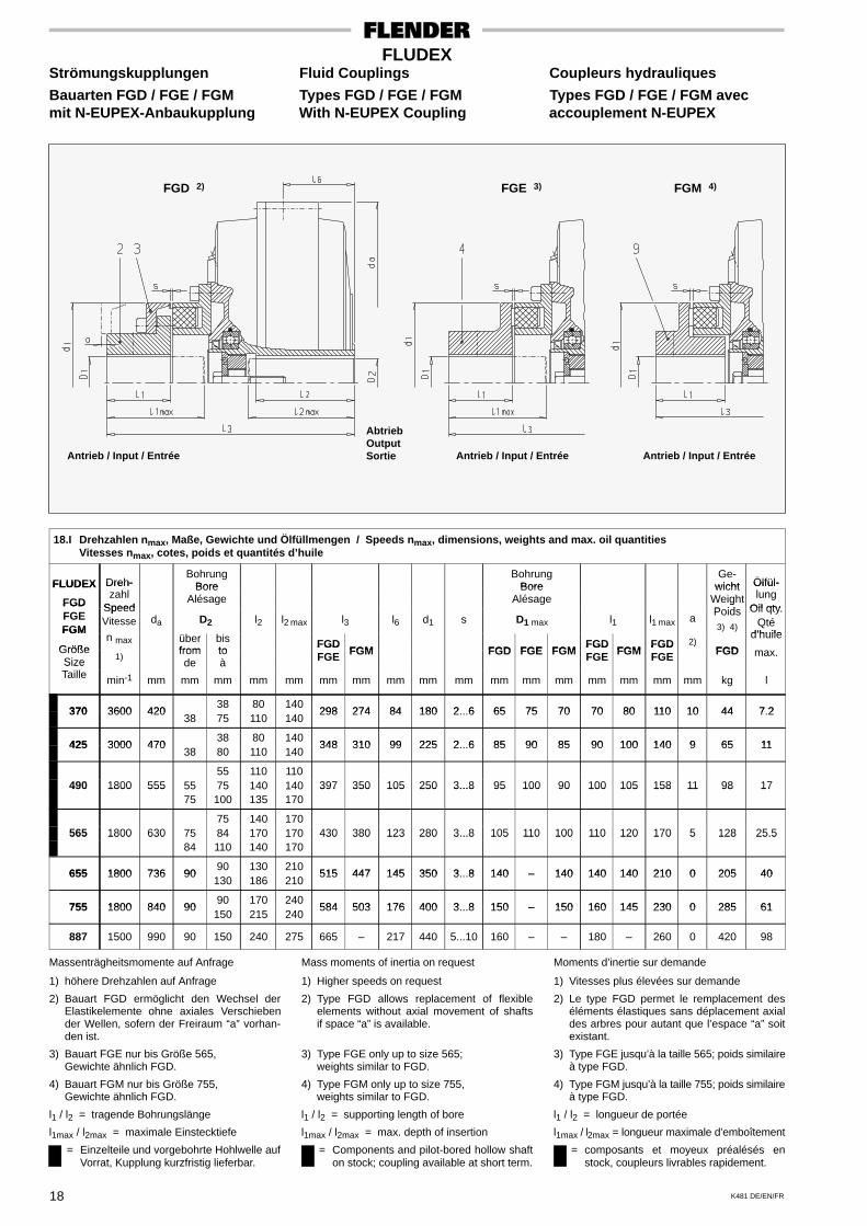
K481 DE/EN/FR18
FLUDEXStrömungskupplungen Fluid Couplings Coupleurs hydrauliques
Bauarten FGD / FGE / FGM Types FGD / FGE / FGM Types FGD / FGE / FGM avecmit N-EUPEX-Anbaukupplung With N-EUPEX Coupling accouplement N-EUPEX
FGD 2)
Antrieb / Input / Entrée
FGM 4)
Antrieb / Input / Entrée
FGE 3)
Antrieb / Input / Entrée
AbtriebOutputSortie
18.I Drehzahlen nmax, Maße, Gewichte und Ölfüllmengen / Speeds nmax, dimensions, weights and max. oil quantitiesVitesses nmax, cotes, poids et quantités d’huile
FLUDEX Dreh-Bohrung
BoreBohrung
BoreGe-
wicht Ölfül-FLUDEX
FGD
Dreh-zahl
Speed
BoreAlésage
BoreAlésage
wichtWeightP id
Ölfül-lung
Oil qtyFGDFGEFGM
SpeedVitesse da D2 l2 l2 max l3 l6 d1 s D1 max l1 l1 max a
gPoids3) 4)
Oil qty.Qté
d’huileFGM
Größen max über
frombisto
FGDFGM FGD FGE FGM
FGDFGM
FGD 2)FGD
d’huile
maxGrößeSize 1)
fromde
toà
FGDFGE FGM FGD FGE FGM
FGDFGE FGM
FGDFGE
)FGD max.
SizeTaille min-1 mm mm mm mm mm mm mm mm mm mm mm mm mm mm mm mm mm kg l
370 3600 42038 80 140
298 274 84 180 2 6 65 75 70 70 80 110 10 44 7 2370 3600 42038 75 110 140
298 274 84 180 2...6 65 75 70 70 80 110 10 44 7.2
425 3000 47038 80 140
348 310 99 225 2 6 85 90 85 90 100 140 9 65 11425 3000 47038 80 110 140
348 310 99 225 2...6 85 90 85 90 100 140 9 65 11
55 110 110490 1800 555 55 75 140 140 397 350 105 250 3...8 95 100 90 100 105 158 11 98 17490 1800 555
75 100 135 170397 350 105 250 3...8 95 100 90 100 105 158 11 98 17
75 140 170565 1800 630 75 84 170 170 430 380 123 280 3...8 105 110 100 110 120 170 5 128 25.5565 1800 630
84 110 140 170430 380 123 280 3...8 105 110 100 110 120 170 5 128 25.5
655 1800 736 9090 130 210
515 447 145 350 3 8 140 – 140 140 140 210 0 205 40655 1800 736 90130 186 210
515 447 145 350 3...8 140 – 140 140 140 210 0 205 40
755 1800 840 9090 170 240
584 503 176 400 3 8 150 – 150 160 145 230 0 285 61755 1800 840 90150 215 240
584 503 176 400 3...8 150 – 150 160 145 230 0 285 61
887 1500 990 90 150 240 275 665 – 217 440 5...10 160 – – 180 – 260 0 420 98
Massenträgheitsmomente auf Anfrage
1) höhere Drehzahlen auf Anfrage
2) Bauart FGD ermöglicht den Wechsel derElastikelemente ohne axiales Verschiebender Wellen, sofern der Freiraum “a” vorhan-den ist.
3) Bauart FGE nur bis Größe 565,Gewichte ähnlich FGD.
4) Bauart FGM nur bis Größe 755,Gewichte ähnlich FGD.
l1 / l2 = tragende Bohrungslänge
l1max / l2max = maximale Einstecktiefe
= Einzelteile und vorgebohrte Hohlwelle aufVorrat, Kupplung kurzfristig lieferbar.
Mass moments of inertia on request
1) Higher speeds on request
2) Type FGD allows replacement of flexibleelements without axial movement of shaftsif space “a” is available.
3) Type FGE only up to size 565;weights similar to FGD.
4) Type FGM only up to size 755,weights similar to FGD.
l1 / l2 = supporting length of bore
l1max / l2max = max. depth of insertion
= Components and pilot-bored hollow shafton stock; coupling available at short term.
Moments d’inertie sur demande
1) Vitesses plus élevées sur demande
2) Le type FGD permet le remplacement deséléments élastiques sans déplacement axialdes arbres pour autant que l’espace “a” soitexistant.
3) Type FGE jusqu’à la taille 565; poids similaireà type FGD.
4) Type FGM jusqu’à la taille 755; poids similaireà type FGD.
l1 / l2 = longueur de portée
l1max / l2max = longueur maximale d’emboîtement
= composants et moyeux préalésés enstock, coupleurs livrables rapidement.
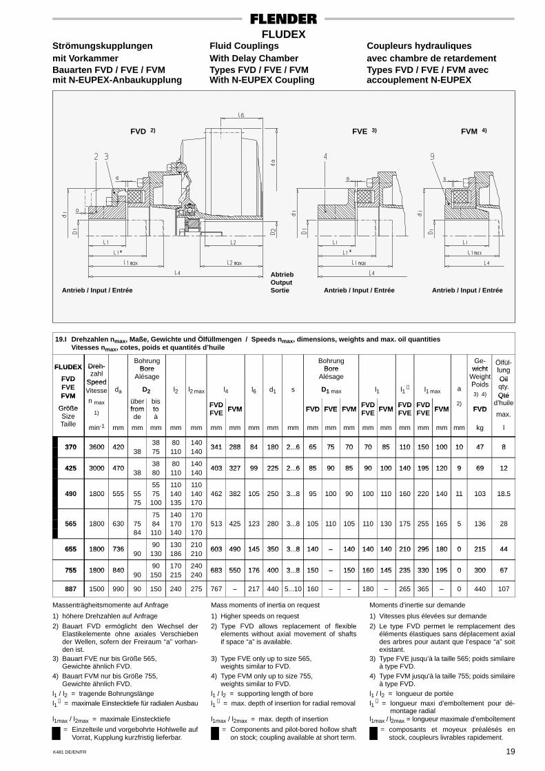
K481 DE/EN/FR 19
FLUDEXStrömungskupplungen Fluid Couplings Coupleurs hydrauliquesmit Vorkammer With Delay Chamber avec chambre de retardementBauarten FVD / FVE / FVM Types FVD / FVE / FVM Types FVD / FVE / FVM avecmit N-EUPEX-Anbaukupplung With N-EUPEX Coupling accouplement N-EUPEX
FVD 2)
Antrieb / Input / Entrée
FVM 4)
Antrieb / Input / Entrée
FVE 3)
Antrieb / Input / Entrée
AbtriebOutputSortie
19.I Drehzahlen nmax, Maße, Gewichte und Ölfüllmengen / Speeds nmax, dimensions, weights and max. oil quantitiesVitesses nmax, cotes, poids et quantités d’huile
FLUDEX Dreh-Bohrung
BoreBohrung
BoreGe-
wichtÖlfül-lungFLUDEX
FVD
Dreh-zahl
Speed
BoreAlésage
BoreAlésage
wichtWeightP id
lungOilFVD
FVEFVM
SpeedVitesse da D2 l2 l2 max l4 l6 d1 s D1 max l1 l1
∗ l1 max a
gPoids3) 4)
Oilqty.QtéFVM
Größen max über
frombisto
FVDFVM FVD FVE FVM
FVDFVM
FVD FVDFVM
2)FVD
Qtéd’huile
GrößeSize 1)
fromde
toà
FVDFVE FVM FVD FVE FVM
FVDFVE FVM
FVDFVE
FVDFVE FVM
)FVD
max.SizeTaille min-1 mm mm mm mm mm mm mm mm mm mm mm mm mm mm mm mm mm mm mm kg l
370 3600 42038 80 140
341 288 84 180 2 6 65 75 70 70 85 110 150 100 10 47 8370 3600 42038 75 110 140
341 288 84 180 2...6 65 75 70 70 85 110 150 100 10 47 8
425 3000 47038 80 140
403 327 99 225 2 6 85 90 85 90 100 140 195 120 9 69 12425 3000 47038 80 110 140
403 327 99 225 2...6 85 90 85 90 100 140 195 120 9 69 12
55 110 110490 1800 555 55 75 140 140 462 382 105 250 3...8 95 100 90 100 110 160 220 140 11 103 18.5490 1800 555
75 100 135 170462 382 105 250 3...8 95 100 90 100 110 160 220 140 11 103 18.5
75 140 170565 1800 630 75 84 170 170 513 425 123 280 3...8 105 110 105 110 130 175 255 165 5 136 28565 1800 630
84 110 140 170513 425 123 280 3...8 105 110 105 110 130 175 255 165 5 136 28
655 1800 73690 130 210
603 490 145 350 3 8 140 – 140 140 140 210 295 180 0 215 44655 1800 73690 130 186 210
603 490 145 350 3...8 140 – 140 140 140 210 295 180 0 215 44
755 1800 84090 170 240
683 550 176 400 3 8 150 – 150 160 145 235 330 195 0 300 67755 1800 84090 150 215 240
683 550 176 400 3...8 150 – 150 160 145 235 330 195 0 300 67
887 1500 990 90 150 240 275 767 – 217 440 5...10 160 – – 180 – 265 365 – 0 440 107
Massenträgheitsmomente auf Anfrage
1) höhere Drehzahlen auf Anfrage
2) Bauart FVD ermöglicht den Wechsel derElastikelemente ohne axiales Verschiebender Wellen, sofern der Freiraum “a” vorhan-den ist.
3) Bauart FVE nur bis Größe 565,Gewichte ähnlich FVD.
4) Bauart FVM nur bis Größe 755,Gewichte ähnlich FVD.
l1 / l2 = tragende Bohrungslängel1
∗ = maximale Einstecktiefe für radialen Ausbau
l1max / l2max = maximale Einstecktiefe
= Einzelteile und vorgebohrte Hohlwelle aufVorrat, Kupplung kurzfristig lieferbar.
Mass moments of inertia on request
1) Higher speeds on request
2) Type FVD allows replacement of flexibleelements without axial movement of shaftsif space “a” is available.
3) Type FVE only up to size 565,weights similar to FVD.
4) Type FVM only up to size 755,weights similar to FVD.
l1 / l2 = supporting length of borel1
∗ = max. depth of insertion for radial removal
l1max / l2max = max. depth of insertion
= Components and pilot-bored hollow shafton stock; coupling available at short term.
Moments d’inertie sur demande
1) Vitesses plus élevées sur demande
2) Le type FVD permet le remplacement deséléments élastiques sans déplacement axialdes arbres pour autant que l’espace “a” soitexistant.
3) Type FVE jusqu’à la taille 565; poids similaireà type FVD.
4) Type FVM jusqu’à la taille 755; poids similaireà type FVD.
l1 / l2 = longueur de portéel1
∗ = longueur maxi d’emboîtement pour dé-montage radial
l1max / l2max = longueur maximale d’emboîtement
= composants et moyeux préalésés enstock, coupleurs livrables rapidement.
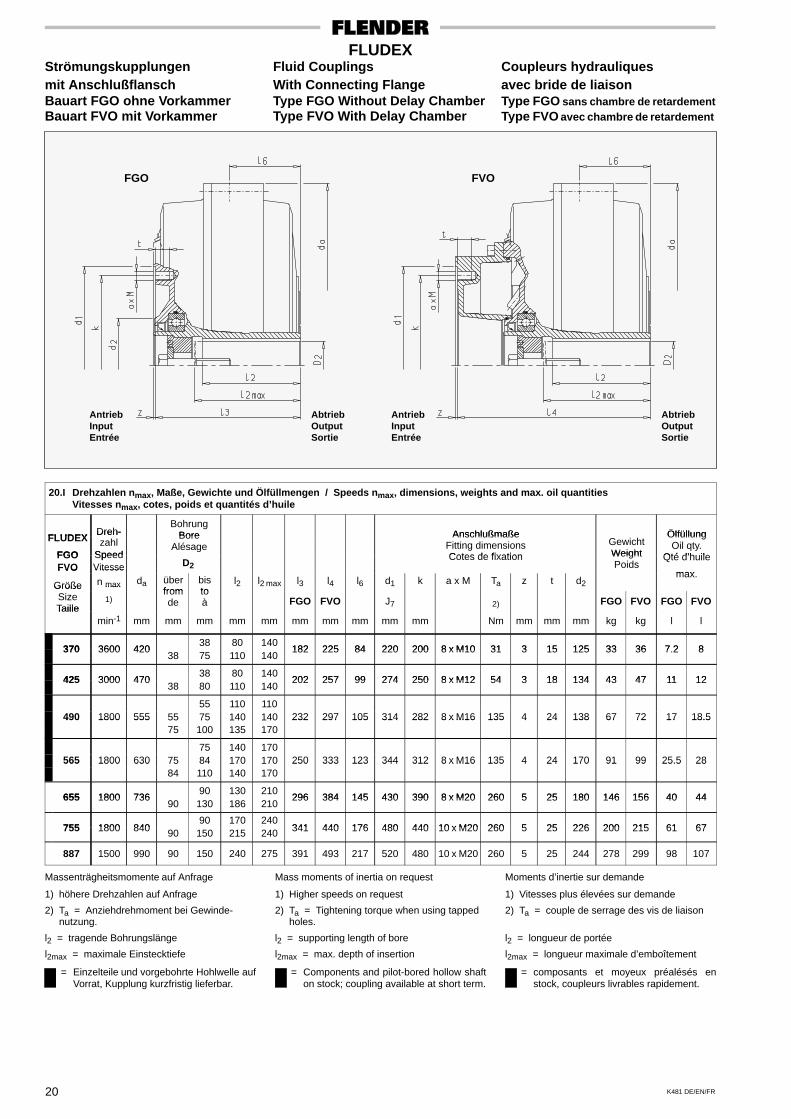
K481 DE/EN/FR20
FLUDEXStrömungskupplungen Fluid Couplings Coupleurs hydrauliquesmit Anschlußflansch With Connecting Flange avec bride de liaisonBauart FGO ohne Vorkammer Type FGO Without Delay Chamber Type FGO sans chambre de retardementBauart FVO mit Vorkammer Type FVO With Delay Chamber Type FVO avec chambre de retardement
AntriebInputEntrée
FVO
AbtriebOutputSortie
FGO
AntriebInputEntrée
AbtriebOutputSortie
20.I Drehzahlen nmax, Maße, Gewichte und Ölfüllmengen / Speeds nmax, dimensions, weights and max. oil quantitiesVitesses nmax, cotes, poids et quantités d’huile
FLUDEXDreh-
BohrungBore Anschlußmaße ÖlfüllungFLUDEX
FGO
Dreh-zahl
Speed
BoreAlésage
AnschlußmaßeFitting dimensionsCotes de fixation
GewichtWeight
ÖlfüllungOil qty.
Qté d’huileFGOFVO
SpeedVitesse D2
Cotes de fixation WeightPoids
Qté d’huile
maxFVO
Größe
Vitesse
n max da überfrom
bisto
l2 l2 max l3 l4 l6 d1 k a x M Ta z t d2max.
GrößeSizeTaille
max
1)fromde
toà FGO FVO J7 2) FGO FVO FGO FVO
Taillemin-1 mm mm mm mm mm mm mm mm mm mm Nm mm mm mm kg kg l l
370 3600 42038 80 140
182 225 84 220 200 8 x M10 31 3 15 125 33 36 7 2 8370 3600 42038 75 110 140
182 225 84 220 200 8 x M10 31 3 15 125 33 36 7.2 8
425 3000 47038 80 140
202 257 99 274 250 8 x M12 54 3 18 134 43 47 11 12425 3000 47038 80 110 140
202 257 99 274 250 8 x M12 54 3 18 134 43 47 11 12
55 110 110490 1800 555 55 75 140 140 232 297 105 314 282 8 x M16 135 4 24 138 67 72 17 18.5490 1800 555
75 100 135 170232 297 105 314 282 8 x M16 135 4 24 138 67 72 17 18.5
75 140 170565 1800 630 75 84 170 170 250 333 123 344 312 8 x M16 135 4 24 170 91 99 25.5 28565 1800 630
84 110 140 170250 333 123 344 312 8 x M16 135 4 24 170 91 99 25.5 28
655 1800 73690 130 210
296 384 145 430 390 8 x M20 260 5 25 180 146 156 40 44655 1800 73690 130 186 210
296 384 145 430 390 8 x M20 260 5 25 180 146 156 40 44
755 1800 84090 170 240
341 440 176 480 440 10 x M20 260 5 25 226 200 215 61 67755 1800 840 90 150 215 240 341 440 176 480 440 10 x M20 260 5 25 226 200 215 61 67
887 1500 990 90 150 240 275 391 493 217 520 480 10 x M20 260 5 25 244 278 299 98 107
Massenträgheitsmomente auf Anfrage
1) höhere Drehzahlen auf Anfrage
2) Ta = Anziehdrehmoment bei Gewinde-nutzung.
l2 = tragende Bohrungslänge
l2max = maximale Einstecktiefe
= Einzelteile und vorgebohrte Hohlwelle aufVorrat, Kupplung kurzfristig lieferbar.
Mass moments of inertia on request
1) Higher speeds on request
2) Ta = Tightening torque when using tappedholes.
l2 = supporting length of bore
l2max = max. depth of insertion
= Components and pilot-bored hollow shafton stock; coupling available at short term.
Moments d’inertie sur demande
1) Vitesses plus élevées sur demande
2) Ta = couple de serrage des vis de liaison
l2 = longueur de portée
l2max = longueur maximale d’emboîtement
= composants et moyeux préalésés enstock, coupleurs livrables rapidement.
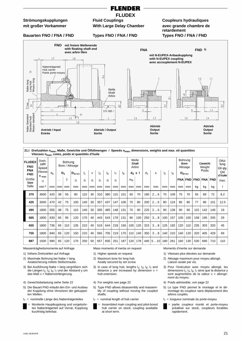
K481 DE/EN/FR 21
FLUDEXStrömungskupplungen Fluid Couplings Coupleurs hydrauliquesmit großer Vorkammer With Large Delay Chamber avec grande chambre de
retardementBauarten FNO / FNA / FND Types FNO / FNA / FND Types FNO / FNA / FND
Antrieb / InputEntrée
Abtrieb / OutputSortie
FNO mit freiem Wellenendewith floating shaft endavec arbre libre
FNA FND 5)
mit N-EUPEX-Anbaukupplungwith N-EUPEX couplingavec accouplement N-EUPEX
WelleShaftArbre
NabenträgerteilHub carrierPartie porte-moyeu
Nab
e la
ngLo
ng h
ubM
oyeu
long
Nab
e S
tand
ard
Sta
ndar
d hu
bM
oyeu
sta
ndar
d
AbtriebOutputSortie
AbtriebOutputSortie
21.I Drehzahlen nmax, Maße, Gewichte und Ölfüllmengen / Speeds nmax, dimensions, weights and max. oil quantitiesVitesses nmax, cotes, poids et quantités d’huile
FLUDEX Dreh-zahl
BohrungWelleShaft
BohrungBore Gewicht
Ölfül-lung
FLUDEX
FNOFNA
zahlSpeed
BohrungBore / Alésage
ShaftArbre
BoreAlésage
GewichtWeightPoids
lungOil qty.
FNAFND
S eedVitessen max
da D1 D1max l1 v l3 l6 l7 l8 d2 x l d1 s l2 l4 D2maxPoids
Oil qty.Qté
d’huileGrößeSize
n max
1) . 3 2) 3) 3) 3) 3) 3) m6 FNA FND FNO FNA FNDd huile
max.SizeTaille min-1 mm mm mm mm mm mm mm mm mm mm mm mm mm mm mm mm mm mm kg kg kg l
370 3600 420 38 55 80 110 30 310 380 115 101 60 70 180 2 ... 6 70 109 75 70 55 69 72 8.2
425 3000 470 42 75 100 140 30 357 437 147 106 70 80 200 2 ... 6 80 124 85 80 77 86 101 12.5
490 1800 555 48 75 110 140 30 395 485 148 131 70 90 225 2 ... 6 90 139 90 90 115 142 149 19
565 1800 630 65 95 120 170 40 443 543 178 131 90 100 250 3 ... 8 100 157 100 100 158 195 205 29
655 1800 736 65 110 135 210 40 519 644 218 156 100 125 315 3 ... 8 125 192 120 110 235 303 320 45
755 1800 840 65 120 150 210 40 565 705 219 170 110 140 350 3 ... 8 140 210 140 120 320 405 429 69
887 1500 990 65 120 170 250 50 657 835 251 187 120 178 440 5 ... 10 180 261 160 130 530 690 710 110
Massenträgheitsmomente auf Anfrage
1) höhere Drehzahlen auf Anfrage
2) Maximale Bohrung bei Nabe = lang.Axialsicherung mittels Stellschraube.
3) Bei Ausführung Nabe = lang vergrößern sichdie Längen l1; l3; l6; l7 und der Abstand y umdas Maß v = Nabenverlängerung.
4) Gewichtsbelastung siehe Seite 22
5) Die Bauart FND erlaubt den Ein- und Ausbauder Kupplung ohne Versetzen der gekuppel-ten Wellen.
l7 = nominelle Länge des Nabenträgerteiles
= Montierte Hauptkupplung und vorgebohr-tes Nabenträgerteil auf Vorrat, Kupplungkurzfristig lieferbar.
Mass moments of inertia on request
1) Higher speeds on request
2) Maximum bore for long hub.Axially secured by set screw.
3) In case of long hub, lengths l1; l3; l6; l7 anddistance y are increased by dimension v =hub extension.
4) For weights see page 22
5) Type FND allows disassembly and reassem-bly of coupling without moving the coupledshafts.
l7 = nominal length of hub carrier
= Assembled main coupling and pilot-boredhub carrier on stock; coupling availableat short term.
Moments d’inertie sur demande
1) Vitesses plus élevées sur demande
2) Alésage maximum pour moyeu allongé.Liaison axiale par vis.
3) Pour l’éxécution avec moyeu allongé, lesdimensions l1; l3; l6; l7 ainsi que la distance ysont augmentées de la valeur v = allonge-ment du moyeu.
4) Poids admissible, voir page 22
5) Le type FND permet le montage et le dé-montage du coupleur sans déplacement desarbres couplés.
l7 = longueur nominale du porte-moyeu
= partie coupleur monté et porte-moyeupréalésé sur stock, coupleurs livrablesrapidement.
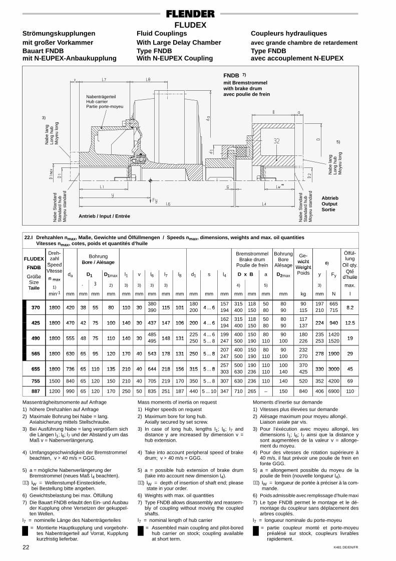
K481 DE/EN/FR22
FLUDEXStrömungskupplungen Fluid Couplings Coupleurs hydrauliquesmit großer Vorkammer With Large Delay Chamber avec grande chambre de retardementBauart FNDB Type FNDB Type FNDBmit N-EUPEX-Anbaukupplung With N-EUPEX Coupling avec accouplement N-EUPEX
Antrieb / Input / Entrée
AbtriebOutputSortie
FNDB 7)
mit Bremstrommelwith brake drumavec poulie de freinNabenträgerteil
Hub carrierPartie porte-moyeu
Nab
e la
ngLo
ng h
ubM
oyeu
long
Nab
e S
tand
ard
Sta
ndar
d hu
bM
oyeu
sta
ndar
d
Nab
e S
tand
ard
Sta
ndar
d hu
bM
oyeu
sta
ndar
d
Nab
e la
ngLo
ng h
ubM
oyeu
long
3)
5)
22.I Drehzahlen nmax, Maße, Gewichte und Ölfüllmengen / Speeds nmax, dimensions, weights and max. oil quantitiesVitesses nmax, cotes, poids et quantités d’huile
FLUDEXDreh-zahl
Speed
BohrungBore / Alésage
BremstrommelBrake drum
P li d f i
BohrungBore
Alé
Ge-wicht 6)
Ölfül-lung
Oil tFNDB SpeedVitesse
Bore / AlésagePoulie de frein Alésage
wichtWeight
6) Oil qty.Qté
FNDB
GrößeVitesse
n maxda D1 D1max l1 v l6 l7 l8 d1 s l4 D x B a D2max
WeightPoids y Fy
Qtéd’huileGröße
SizeTaille
n max
1). 3 2) 3) 3) 3) 3) 4) 5) 3)
d huile
max.Taillemin-1 mm mm mm mm mm mm mm mm mm mm mm mm mm mm mm mm kg mm N l
370 1800 420 38 55 80 110 30380
115 101180
4 6157 315 118 50 80 90 197 665
8 2370 1800 420 38 55 80 110 30 390 115 101 200 4 ... 6 194 400 150 80 90 115 210 715 8.2
425 1800 470 42 75 100 140 30 437 147 106 200 4 6162 315 118 50 80 117
224 940 12 5425 1800 470 42 75 100 140 30 437 147 106 200 4 ... 6 194 400 150 80 90 137 224 940 12.5
490 1800 555 48 75 110 140 30485
148 131225 4 ... 6 199 400 150 80 90 180 235 1420
19490 1800 555 48 75 110 140 30 495 148 131 250 5 ... 8 247 500 190 110 100 226 253 1520 19
565 1800 630 65 95 120 170 40 543 178 131 250 5 8207 400 150 80 90 232
278 1900 29565 1800 630 65 95 120 170 40 543 178 131 250 5 ... 8 247 500 190 110 100 270 278 1900 29
655 1800 736 65 110 135 210 40 644 218 156 315 5 8257 500 190 110 100 370
330 3000 45655 1800 736 65 110 135 210 40 644 218 156 315 5 ... 8 303 630 236 110 140 425 330 3000 45
755 1500 840 65 120 150 210 40 705 219 170 350 5 ... 8 307 630 236 110 140 520 352 4200 69
887 1200 990 65 120 170 250 50 835 251 187 440 5 ... 10 347 710 265 – 150 840 406 6900 110
Massenträgheitsmomente auf Anfrage1) höhere Drehzahlen auf Anfrage2) Maximale Bohrung bei Nabe = lang.
Axialsicherung mittels Stellschraube.3) Bei Ausführung Nabe = lang vergrößern sich
die Längen l1; l6; l7 und der Abstand y um dasMaß v = Nabenverlängerung.
4) Umfangsgeschwindigkeit der Bremstrommelbeachten, v > 40 m/s = GGG.
5) a = mögliche Nabenverlängerung derBremstrommel (neues Maß l4 beachten).
∗∗) lW = Wellenstumpf-Einstecktiefe,bei Bestellung bitte angeben.
6) Gewichtsbelastung bei max. Ölfüllung7) Die Bauart FNDB erlaubt den Ein- und Ausbau
der Kupplung ohne Versetzen der gekuppel-ten Wellen.
l7 = nominelle Länge des Nabenträgerteiles
= Montierte Hauptkupplung und vorgebohr-tes Nabenträgerteil auf Vorrat, Kupplungkurzfristig lieferbar.
Mass moments of inertia on request1) Higher speeds on request2) Maximum bore for long hub.
Axially secured by set screw.3) In case of long hub, lengths l1; l6; l7 and
distance y are increased by dimension v =hub extension.
4) Take into account peripheral speed of brakedrum; v > 40 m/s = GGG.
5) a = possible hub extension of brake drum(take into account new dimension l4).
∗∗) lW = depth of insertion of shaft end; pleasestate in your order.
6) Weights with max. oil quantities7) Type FNDB allows disassembly and reassem-
bly of coupling without moving the coupledshafts.
l7 = nominal length of hub carrier
= Assembled main coupling and pilot-boredhub carrier on stock; coupling availableat short term.
Moments d’inertie sur demande1) Vitesses plus élevées sur demande2) Alésage maximum pour moyeu allongé.
Liaison axiale par vis.3) Pour l’éxécution avec moyeu allongé, les
dimensions l1; l6; l7 ainsi que la distance ysont augmentées de la valeur v = allonge-ment du moyeu.
4) Pour des vitesses de rotation supérieure à40 m/s, il faut prévoir une poulie de frein enfonte GGG.
5) a = allongement possible du moyeu de lapoulie de frein (nouvelle longueur l4).
∗∗) lW = longueur de portée à préciser à la com-mande.
6) Poids admissible avec remplissage d’huile maxi
7) Le type FNDB permet le montage et le dé-montage du coupleur sans déplacement desarbres couplés.
l7 = longueur nominale du porte-moyeu
= partie coupleur monté et porte-moyeupréalésé sur stock, coupleurs livrablesrapidement.
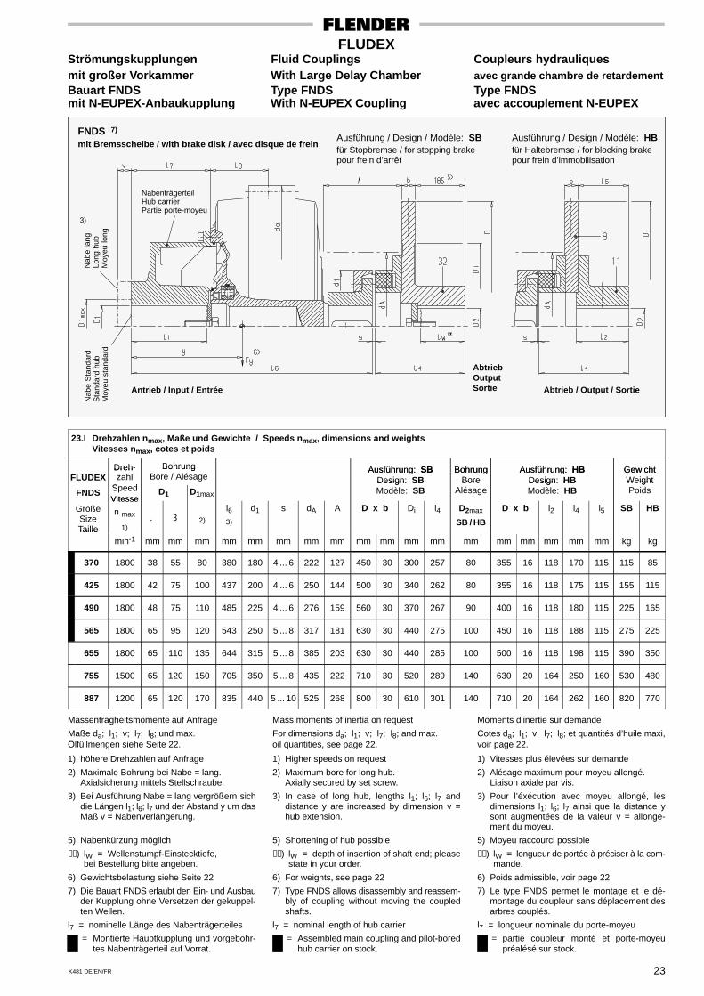
K481 DE/EN/FR 23
FLUDEXStrömungskupplungen Fluid Couplings Coupleurs hydrauliquesmit großer Vorkammer With Large Delay Chamber avec grande chambre de retardementBauart FNDS Type FNDS Type FNDSmit N-EUPEX-Anbaukupplung With N-EUPEX Coupling avec accouplement N-EUPEX
Antrieb / Input / Entrée
NabenträgerteilHub carrierPartie porte-moyeu
Nab
e la
ngLo
ng h
ubM
oyeu
long
Nab
e S
tand
ard
Sta
ndar
d hu
bM
oyeu
sta
ndar
d
Abtrieb / Output / Sortie
AbtriebOutputSortie
FNDS 7)
mit Bremsscheibe / with brake disk / avec disque de freinAusführung / Design / Modèle: SBfür Stopbremse / for stopping brakepour frein d’arrêt
Ausführung / Design / Modèle: HBfür Haltebremse / for blocking brakepour frein d’immobilisation
3)
23.I Drehzahlen nmax, Maße und Gewichte / Speeds nmax, dimensions and weightsVitesses nmax, cotes et poids
Dreh- Bohrung Ausführung: SB Bohrung Ausführung: HB GewichtFLUDEX
Drehzahl
S d
BohrungBore / Alésage
Ausführung: SBDesign: SB
BohrungBore
Ausführung: HBDesign: HB
GewichtWeight
FNDS SpeedVitesse
D1 D1max
Design: SBModèle: SB
BoreAlésage
Design: HBModèle: HB
WeightPoids
GrößeSizeTaille
Vitesse
n max
1). 3 2)
l63)
d1 s dA A D x b Di l4 D2max
SB / HB
D x b l2 l4 l5 SB HB
Taillemin-1 mm mm mm mm mm mm mm mm mm mm mm mm mm mm mm mm mm mm kg kg
370 1800 38 55 80 380 180 4 ... 6 222 127 450 30 300 257 80 355 16 118 170 115 115 85
425 1800 42 75 100 437 200 4 ... 6 250 144 500 30 340 262 80 355 16 118 175 115 155 115
490 1800 48 75 110 485 225 4 ... 6 276 159 560 30 370 267 90 400 16 118 180 115 225 165
565 1800 65 95 120 543 250 5 ... 8 317 181 630 30 440 275 100 450 16 118 188 115 275 225
655 1800 65 110 135 644 315 5 ... 8 385 203 630 30 440 285 100 500 16 118 198 115 390 350
755 1500 65 120 150 705 350 5 ... 8 435 222 710 30 520 289 140 630 20 164 250 160 530 480
887 1200 65 120 170 835 440 5 ... 10 525 268 800 30 610 301 140 710 20 164 262 160 820 770
Massenträgheitsmomente auf Anfrage
Maße da; l1; v; l7; l8; und max.Ölfüllmengen siehe Seite 22.
1) höhere Drehzahlen auf Anfrage
2) Maximale Bohrung bei Nabe = lang.Axialsicherung mittels Stellschraube.
3) Bei Ausführung Nabe = lang vergrößern sichdie Längen l1; l6; l7 und der Abstand y um dasMaß v = Nabenverlängerung.
5) Nabenkürzung möglich
∗∗) lW = Wellenstumpf-Einstecktiefe,bei Bestellung bitte angeben.
6) Gewichtsbelastung siehe Seite 22
7) Die Bauart FNDS erlaubt den Ein- und Ausbauder Kupplung ohne Versetzen der gekuppel-ten Wellen.
l7 = nominelle Länge des Nabenträgerteiles
= Montierte Hauptkupplung und vorgebohr-tes Nabenträgerteil auf Vorrat.
Mass moments of inertia on request
For dimensions da; l1; v; l7; l8; and max.oil quantities, see page 22.
1) Higher speeds on request
2) Maximum bore for long hub.Axially secured by set screw.
3) In case of long hub, lengths l1; l6; l7 anddistance y are increased by dimension v =hub extension.
5) Shortening of hub possible
∗∗) lW = depth of insertion of shaft end; pleasestate in your order.
6) For weights, see page 22
7) Type FNDS allows disassembly and reassem-bly of coupling without moving the coupledshafts.
l7 = nominal length of hub carrier
= Assembled main coupling and pilot-boredhub carrier on stock.
Moments d’inertie sur demande
Cotes da; l1; v; l7; l8; et quantités d’huile maxi,voir page 22.
1) Vitesses plus élevées sur demande
2) Alésage maximum pour moyeu allongé.Liaison axiale par vis.
3) Pour l’éxécution avec moyeu allongé, lesdimensions l1; l6; l7 ainsi que la distance ysont augmentées de la valeur v = allonge-ment du moyeu.
5) Moyeu raccourci possible
∗∗) lW = longueur de portée à préciser à la com-mande.
6) Poids admissible, voir page 22
7) Le type FNDS permet le montage et le dé-montage du coupleur sans déplacement desarbres couplés.
l7 = longueur nominale du porte-moyeu
= partie coupleur monté et porte-moyeupréalésé sur stock.
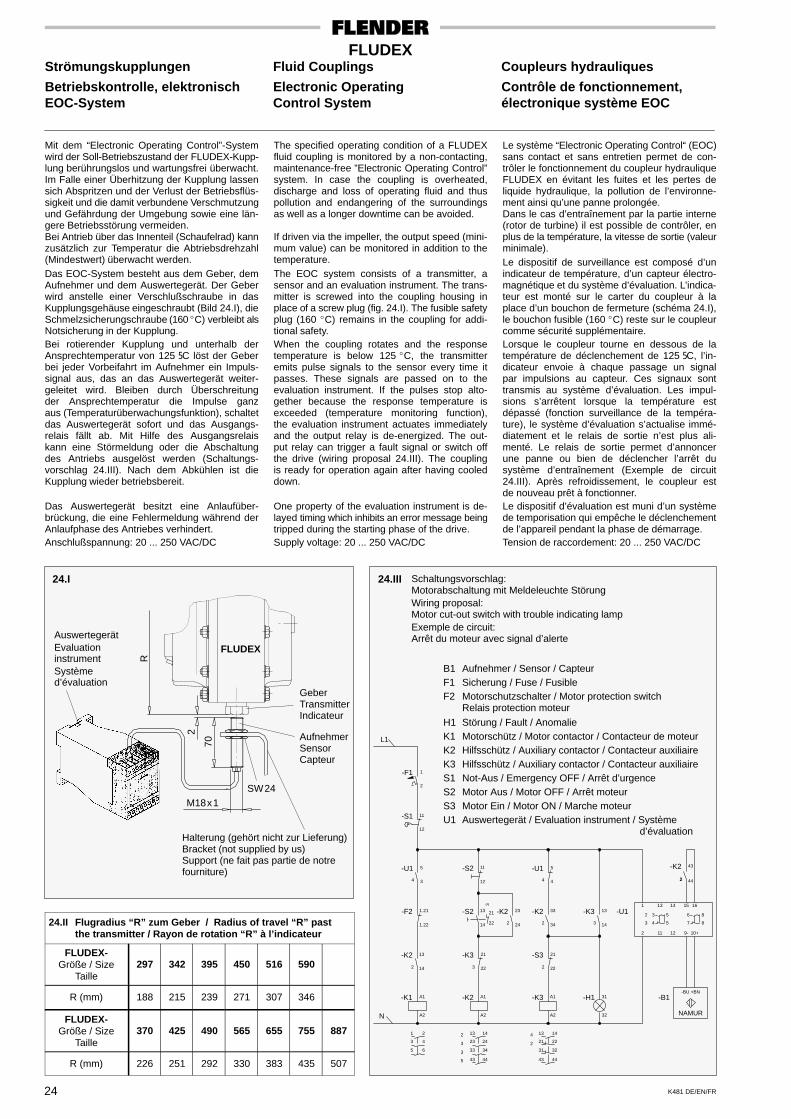
K481 DE/EN/FR24
FLUDEXStrömungskupplungen Fluid Couplings Coupleurs hydrauliques
Betriebskontrolle, elektronisch Electronic Operating Contrôle de fonctionnement,EOC-System Control System électronique système EOC
Mit dem “Electronic Operating Control”-Systemwird der Soll-Betriebszustand der FLUDEX-Kupp-lung berührungslos und wartungsfrei überwacht.Im Falle einer Überhitzung der Kupplung lassensich Abspritzen und der Verlust der Betriebsflüs-sigkeit und die damit verbundene Verschmutzungund Gefährdung der Umgebung sowie eine län-gere Betriebsstörung vermeiden.Bei Antrieb über das Innenteil (Schaufelrad) kannzusätzlich zur Temperatur die Abtriebsdrehzahl(Mindestwert) überwacht werden.Das EOC-System besteht aus dem Geber, demAufnehmer und dem Auswertegerät. Der Geberwird anstelle einer Verschlußschraube in dasKupplungsgehäuse eingeschraubt (Bild 24.I), dieSchmelzsicherungschraube (160�C) verbleibt alsNotsicherung in der Kupplung.Bei rotierender Kupplung und unterhalb derAnsprechtemperatur von 125 5C löst der Geberbei jeder Vorbeifahrt im Aufnehmer ein Impuls-signal aus, das an das Auswertegerät weiter-geleitet wird. Bleiben durch Überschreitungder Ansprechtemperatur die Impulse ganzaus (Temperaturüberwachungsfunktion), schaltetdas Auswertegerät sofort und das Ausgangs-relais fällt ab. Mit Hilfe des Ausgangsrelaiskann eine Störmeldung oder die Abschaltungdes Antriebs ausgelöst werden (Schaltungs-vorschlag 24.III). Nach dem Abkühlen ist dieKupplung wieder betriebsbereit.
Das Auswertegerät besitzt eine Anlaufüber-brückung, die eine Fehlermeldung während derAnlaufphase des Antriebes verhindert.Anschlußspannung: 20 ... 250 VAC/DC
The specified operating condition of a FLUDEXfluid coupling is monitored by a non-contacting,maintenance-free ”Electronic Operating Control”system. In case the coupling is overheated,discharge and loss of operating fluid and thuspollution and endangering of the surroundingsas well as a longer downtime can be avoided.
If driven via the impeller, the output speed (mini-mum value) can be monitored in addition to thetemperature.The EOC system consists of a transmitter, asensor and an evaluation instrument. The trans-mitter is screwed into the coupling housing inplace of a screw plug (fig. 24.I). The fusible safetyplug (160 �C) remains in the coupling for addi-tional safety.When the coupling rotates and the responsetemperature is below 125 �C, the transmitteremits pulse signals to the sensor every time itpasses. These signals are passed on to theevaluation instrument. If the pulses stop alto-gether because the response temperature isexceeded (temperature monitoring function),the evaluation instrument actuates immediatelyand the output relay is de-energized. The out-put relay can trigger a fault signal or switch offthe drive (wiring proposal 24.III). The couplingis ready for operation again after having cooleddown.
One property of the evaluation instrument is de-layed timing which inhibits an error message beingtripped during the starting phase of the drive.Supply voltage: 20 ... 250 VAC/DC
Le système “Electronic Operating Control“ (EOC)sans contact et sans entretien permet de con-trôler le fonctionnement du coupleur hydrauliqueFLUDEX en évitant les fuites et les pertes deliquide hydraulique, la pollution de l’environne-ment ainsi qu’une panne prolongée.Dans le cas d’entraînement par la partie interne(rotor de turbine) il est possible de contrôler, enplus de la température, la vitesse de sortie (valeurminimale).Le dispositif de surveillance est composé d’unindicateur de température, d’un capteur électro-magnétique et du système d’évaluation. L’indica-teur est monté sur le carter du coupleur à laplace d’un bouchon de fermeture (schéma 24.I),le bouchon fusible (160 �C) reste sur le coupleurcomme sécurité supplémentaire.Lorsque le coupleur tourne en dessous de latempérature de déclenchement de 125 5C, l’in-dicateur envoie à chaque passage un signalpar impulsions au capteur. Ces signaux sonttransmis au système d’évaluation. Les impul-sions s’arrêtent lorsque la température estdépassé (fonction surveillance de la tempéra-ture), le système d’évaluation s’actualise immé-diatement et le relais de sortie n’est plus ali-menté. Le relais de sortie permet d’annoncerune panne ou bien de déclencher l’arrêt dusystème d’entraînement (Exemple de circuit24.III). Après refroidissement, le coupleur estde nouveau prêt à fonctionner.Le dispositif d’évaluation est muni d’un systèmede temporisation qui empêche le déclenchementde l’appareil pendant la phase de démarrage.Tension de raccordement: 20 ... 250 VAC/DC
24.II Flugradius “R” zum Geber / Radius of travel “R” pastthe transmitter / Rayon de rotation “R” à l’indicateur
FLUDEX-Größe / Size
Taille297 342 395 450 516 590
R (mm) 188 215 239 271 307 346
FLUDEX-Größe / Size
Taille370 425 490 565 655 755 887
R (mm) 226 251 292 330 383 435 507
24.I 24.III
AuswertegerätEvaluationinstrumentSystèmed’évaluation
GeberTransmitterIndicateur
AufnehmerSensorCapteur
Halterung (gehört nicht zur Lieferung)Bracket (not supplied by us)Support (ne fait pas partie de notrefourniture)
Schaltungsvorschlag:Motorabschaltung mit Meldeleuchte StörungWiring proposal:Motor cut-out switch with trouble indicating lampExemple de circuit:Arrêt du moteur avec signal d’alerte
B1 Aufnehmer / Sensor / CapteurF1 Sicherung / Fuse / FusibleF2 Motorschutzschalter / Motor protection switch
Relais protection moteur
H1 Störung / Fault / AnomalieK1 Motorschütz / Motor contactor / Contacteur de moteurK2 Hilfsschütz / Auxiliary contactor / Contacteur auxiliaireK3 Hilfsschütz / Auxiliary contactor / Contacteur auxiliaireS1 Not-Aus / Emergency OFF / Arrêt d’urgenceS2 Motor Aus / Motor OFF / Arrêt moteurS3 Motor Ein / Motor ON / Marche moteurU1 Auswertegerät / Evaluation instrument / Système
d’évaluation
FLUDEX
R
2
70
M18x1
SW24
NAMUR
-B1-BU +BN
14
22
32
4443
31
21
134
2
-H1-K3-K2-K1
43-K2
11
2
1
32
43
2
2
12 9- 10+
13 14 15 16
5
5
6
7
8
8
-K3 -U1-K2
32
31
14
13
3
A2
A1
-S3 21
222
33
342
5
4
-U14
-K3 21
223
A2
A1
A2
A1
-K2 13
142
-F2 1.21
1.22
-K2 23
242
-S2 13
14 22
21
3
-S2 11
12
5
3
-U14
N
L1
11
12
-S1
1
2
-F1
14
24
34
4443
33
23
132
3
3
5
5
3
1
6
4
2
44
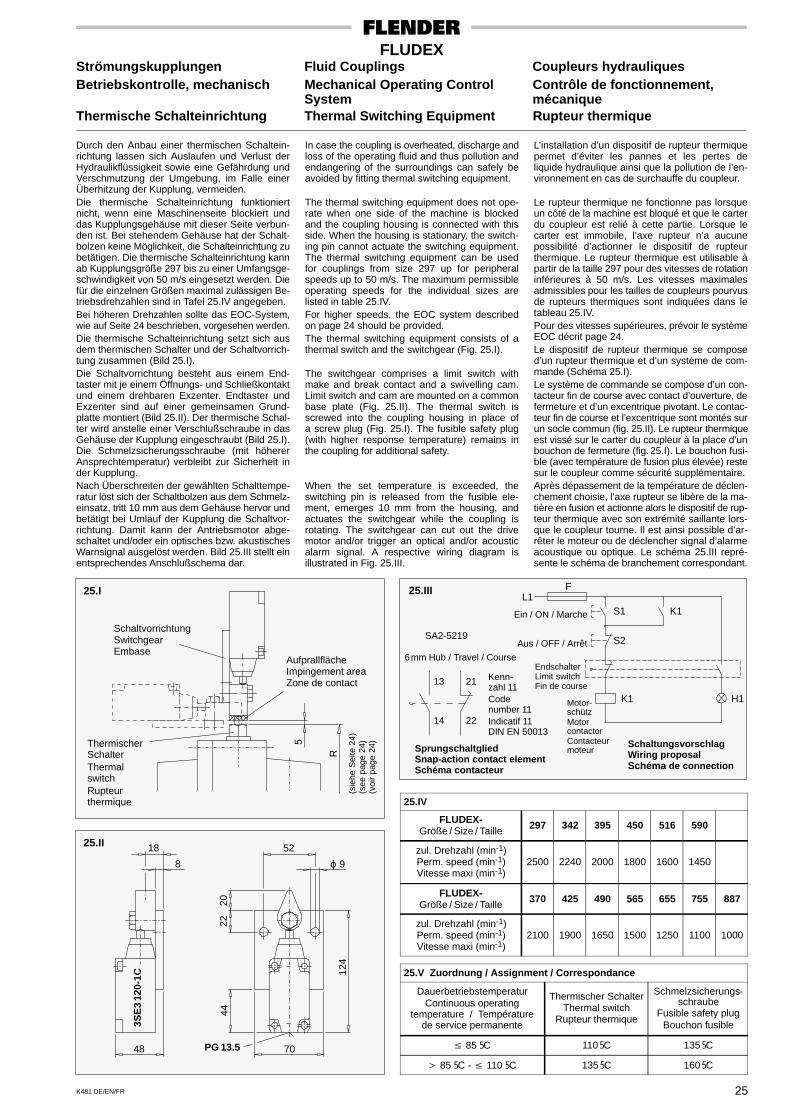
K481 DE/EN/FR 25
FLUDEXStrömungskupplungen Fluid Couplings Coupleurs hydrauliquesBetriebskontrolle, mechanisch Mechanical Operating Control Contrôle de fonctionnement,
System mécaniqueThermische Schalteinrichtung Thermal Switching Equipment Rupteur thermique
Durch den Anbau einer thermischen Schaltein-richtung lassen sich Auslaufen und Verlust derHydraulikflüssigkeit sowie eine Gefährdung undVerschmutzung der Umgebung, im Falle einerÜberhitzung der Kupplung, vermeiden.Die thermische Schalteinrichtung funktioniertnicht, wenn eine Maschinenseite blockiert unddas Kupplungsgehäuse mit dieser Seite verbun-den ist. Bei stehendem Gehäuse hat der Schalt-bolzen keine Möglichkeit, die Schalteinrichtung zubetätigen. Die thermische Schalteinrichtung kannab Kupplungsgröße 297 bis zu einer Umfangsge-schwindigkeit von 50 m/s eingesetzt werden. Diefür die einzelnen Größen maximal zulässigen Be-triebsdrehzahlen sind in Tafel 25.IV angegeben.Bei höheren Drehzahlen sollte das EOC-System,wie auf Seite 24 beschrieben, vorgesehen werden.Die thermische Schalteinrichtung setzt sich ausdem thermischen Schalter und der Schaltvorrich-tung zusammen (Bild 25.I).Die Schaltvorrichtung besteht aus einem End-taster mit je einem Öffnungs- und Schließkontaktund einem drehbaren Exzenter. Endtaster undExzenter sind auf einer gemeinsamen Grund-platte montiert (Bild 25.II). Der thermische Schal-ter wird anstelle einer Verschlußschraube in dasGehäuse der Kupplung eingeschraubt (Bild 25.I).Die Schmelzsicherungsschraube (mit höhererAnsprechtemperatur) verbleibt zur Sicherheit inder Kupplung.Nach Überschreiten der gewählten Schalttempe-ratur löst sich der Schaltbolzen aus dem Schmelz-einsatz, tritt 10 mm aus dem Gehäuse hervor undbetätigt bei Umlauf der Kupplung die Schaltvor-richtung. Damit kann der Antriebsmotor abge-schaltet und/oder ein optisches bzw. akustischesWarnsignal ausgelöst werden. Bild 25.III stellt einentsprechendes Anschlußschema dar.
In case the coupling is overheated, discharge andloss of the operating fluid and thus pollution andendangering of the surroundings can safely beavoided by fitting thermal switching equipment.
The thermal switching equipment does not ope-rate when one side of the machine is blockedand the coupling housing is connected with thisside. When the housing is stationary, the switch-ing pin cannot actuate the switching equipment.The thermal switching equipment can be usedfor couplings from size 297 up for peripheralspeeds up to 50 m/s. The maximum permissibleoperating speeds for the individual sizes arelisted in table 25.IV.For higher speeds, the EOC system describedon page 24 should be provided.The thermal switching equipment consists of athermal switch and the switchgear (Fig. 25.I).
The switchgear comprises a limit switch withmake and break contact and a swivelling cam.Limit switch and cam are mounted on a commonbase plate (Fig. 25.II). The thermal switch isscrewed into the coupling housing in place ofa screw plug (Fig. 25.I). The fusible safety plug(with higher response temperature) remains inthe coupling for additional safety.
When the set temperature is exceeded, theswitching pin is released from the fusible ele-ment, emerges 10 mm from the housing, andactuates the switchgear while the coupling isrotating. The switchgear can cut out the drivemotor and/or trigger an optical and/or acousticalarm signal. A respective wiring diagram isillustrated in Fig. 25.III.
L’installation d’un dispositif de rupteur thermiquepermet d’éviter les pannes et les pertes deliquide hydraulique ainsi que la pollution de l’en-vironnement en cas de surchauffe du coupleur.
Le rupteur thermique ne fonctionne pas lorsqueun côté de la machine est bloqué et que le carterdu coupleur est relié à cette partie. Lorsque lecarter est immobile, l’axe rupteur n’a aucunepossibilité d’actionner le dispositif de rupteurthermique. Le rupteur thermique est utilisable àpartir de la taille 297 pour des vitesses de rotationinférieures à 50 m/s. Les vitesses maximalesadmissibles pour les tailles de coupleurs pourvusde rupteurs thermiques sont indiquées dans letableau 25.IV.Pour des vitesses supérieures, prévoir le systèmeEOC décrit page 24.Le dispositif de rupteur thermique se composed’un rupteur thermique et d’un système de com-mande (Schéma 25.I).Le système de commande se compose d’un con-tacteur fin de course avec contact d’ouverture, defermeture et d’un excentrique pivotant. Le contac-teur fin de course et l’excentrique sont montés surun socle commun (fig. 25.II). Le rupteur thermiqueest vissé sur le carter du coupleur à la place d’unbouchon de fermeture (fig. 25.I). Le bouchon fusi-ble (avec température de fusion plus élevée) restesur le coupleur comme sécurité supplémentaire.Après dépassement de la température de déclen-chement choisie, l’axe rupteur se libère de la ma-tière en fusion et actionne alors le dispositif de rup-teur thermique avec son extrémité saillante lors-que le coupleur tourne. Il est ainsi possible d’ar-rêter le moteur ou de déclencher signal d’alarmeacoustique ou optique. Le schéma 25.III repré-sente le schéma de branchement correspondant.
25.IV
FLUDEX-Größe / Size / Taille 297 342 395 450 516 590
zul. Drehzahl (min-1)Perm. speed (min-1)Vitesse maxi (min-1)
2500 2240 2000 1800 1600 1450
FLUDEX-Größe / Size / Taille 370 425 490 565 655 755 887
zul. Drehzahl (min-1)Perm. speed (min-1)Vitesse maxi (min-1)
2100 1900 1650 1500 1250 1100 1000
25.V Zuordnung / Assignment / Correspondance
DauerbetriebstemperaturContinuous operating
temperature / Températurede service permanente
Thermischer SchalterThermal switch
Rupteur thermique
Schmelzsicherungs-schraube
Fusible safety plugBouchon fusible
� 85 5C 110 5C 135 5C
� 85 5C - � 110 5C 135 5C 160 5C
25.III25.I
5
25.II
SchaltvorrichtungSwitchgearEmbase
AufprallflächeImpingement areaZone de contact
R
ThermischerSchalterThermalswitchRupteurthermique
(sie
he S
eite
24)
(see
pag
e 24
)(v
oir
page
24)
18
8
48
3SE
312
0-1C
52
ϕ 9
70PG 13.5
124
2022
44
SA2-5219
Kenn-zahl 11Codenumber 11Indicatif 11DIN EN 50013
EndschalterLimit switchFin de course
Motor-schützMotorcontactorContacteurmoteur
SchaltungsvorschlagWiring proposalSchéma de connection
SprungschaltgliedSnap-action contact elementSchéma contacteur
6mm Hub / Travel / Course
Ein / ON / Marche
Aus / OFF / Arrêt
K1
K1
S1
S2
H1
FL1
13
14 22
21
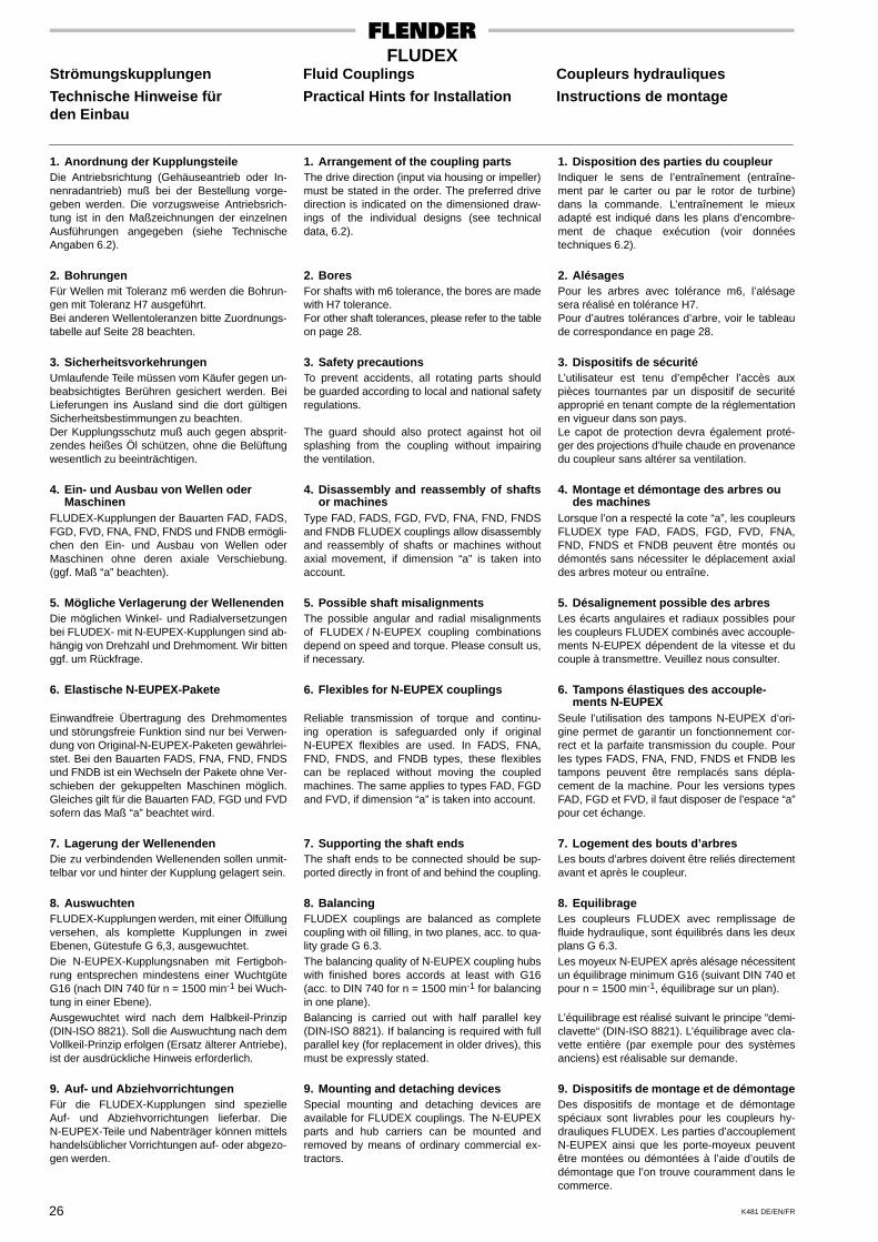
K481 DE/EN/FR26
FLUDEXStrömungskupplungen Fluid Couplings Coupleurs hydrauliques
Technische Hinweise für Practical Hints for Installation Instructions de montageden Einbau
1. Anordnung der KupplungsteileDie Antriebsrichtung (Gehäuseantrieb oder In-nenradantrieb) muß bei der Bestellung vorge-geben werden. Die vorzugsweise Antriebsrich-tung ist in den Maßzeichnungen der einzelnenAusführungen angegeben (siehe TechnischeAngaben 6.2).
2. BohrungenFür Wellen mit Toleranz m6 werden die Bohrun-gen mit Toleranz H7 ausgeführt.Bei anderen Wellentoleranzen bitte Zuordnungs-tabelle auf Seite 28 beachten.
3. SicherheitsvorkehrungenUmlaufende Teile müssen vom Käufer gegen un-beabsichtigtes Berühren gesichert werden. BeiLieferungen ins Ausland sind die dort gültigenSicherheitsbestimmungen zu beachten.Der Kupplungsschutz muß auch gegen absprit-zendes heißes Öl schützen, ohne die Belüftungwesentlich zu beeinträchtigen.
4. Ein- und Ausbau von Wellen oderMaschinen
FLUDEX-Kupplungen der Bauarten FAD, FADS,FGD, FVD, FNA, FND, FNDS und FNDB ermögli-chen den Ein- und Ausbau von Wellen oderMaschinen ohne deren axiale Verschiebung.(ggf. Maß “a” beachten).
5. Mögliche Verlagerung der WellenendenDie möglichen Winkel- und Radialversetzungenbei FLUDEX- mit N-EUPEX-Kupplungen sind ab-hängig von Drehzahl und Drehmoment. Wir bittenggf. um Rückfrage.
6. Elastische N-EUPEX-Pakete
Einwandfreie Übertragung des Drehmomentesund störungsfreie Funktion sind nur bei Verwen-dung von Original-N-EUPEX-Paketen gewährlei-stet. Bei den Bauarten FADS, FNA, FND, FNDSund FNDB ist ein Wechseln der Pakete ohne Ver-schieben der gekuppelten Maschinen möglich.Gleiches gilt für die Bauarten FAD, FGD und FVDsofern das Maß “a” beachtet wird.
7. Lagerung der WellenendenDie zu verbindenden Wellenenden sollen unmit-telbar vor und hinter der Kupplung gelagert sein.
8. AuswuchtenFLUDEX-Kupplungen werden, mit einer Ölfüllungversehen, als komplette Kupplungen in zweiEbenen, Gütestufe G 6,3, ausgewuchtet.Die N-EUPEX-Kupplungsnaben mit Fertigboh-rung entsprechen mindestens einer WuchtgüteG16 (nach DIN 740 für n = 1500 min-1 bei Wuch-tung in einer Ebene).Ausgewuchtet wird nach dem Halbkeil-Prinzip(DIN-ISO 8821). Soll die Auswuchtung nach demVollkeil-Prinzip erfolgen (Ersatz älterer Antriebe),ist der ausdrückliche Hinweis erforderlich.
9. Auf- und AbziehvorrichtungenFür die FLUDEX-Kupplungen sind spezielleAuf- und Abziehvorrichtungen lieferbar. DieN-EUPEX-Teile und Nabenträger können mittelshandelsüblicher Vorrichtungen auf- oder abgezo-gen werden.
1. Arrangement of the coupling partsThe drive direction (input via housing or impeller)must be stated in the order. The preferred drivedirection is indicated on the dimensioned draw-ings of the individual designs (see technicaldata, 6.2).
2. BoresFor shafts with m6 tolerance, the bores are madewith H7 tolerance.For other shaft tolerances, please refer to the tableon page 28.
3. Safety precautionsTo prevent accidents, all rotating parts shouldbe guarded according to local and national safetyregulations.
The guard should also protect against hot oilsplashing from the coupling without impairingthe ventilation.
4. Disassembly and reassembly of shaftsor machines
Type FAD, FADS, FGD, FVD, FNA, FND, FNDSand FNDB FLUDEX couplings allow disassemblyand reassembly of shafts or machines withoutaxial movement, if dimension “a” is taken intoaccount.
5. Possible shaft misalignmentsThe possible angular and radial misalignmentsof FLUDEX / N-EUPEX coupling combinationsdepend on speed and torque. Please consult us,if necessary.
6. Flexibles for N-EUPEX couplings
Reliable transmission of torque and continu-ing operation is safeguarded only if originalN-EUPEX flexibles are used. In FADS, FNA,FND, FNDS, and FNDB types, these flexiblescan be replaced without moving the coupledmachines. The same applies to types FAD, FGDand FVD, if dimension “a” is taken into account.
7. Supporting the shaft endsThe shaft ends to be connected should be sup-ported directly in front of and behind the coupling.
8. BalancingFLUDEX couplings are balanced as completecoupling with oil filling, in two planes, acc. to qua-lity grade G 6.3.The balancing quality of N-EUPEX coupling hubswith finished bores accords at least with G16(acc. to DIN 740 for n = 1500 min-1 for balancingin one plane).Balancing is carried out with half parallel key(DIN-ISO 8821). If balancing is required with fullparallel key (for replacement in older drives), thismust be expressly stated.
9. Mounting and detaching devicesSpecial mounting and detaching devices areavailable for FLUDEX couplings. The N-EUPEXparts and hub carriers can be mounted andremoved by means of ordinary commercial ex-tractors.
1. Disposition des parties du coupleurIndiquer le sens de l’entraînement (entraîne-ment par le carter ou par le rotor de turbine)dans la commande. L’entraînement le mieuxadapté est indiqué dans les plans d’encombre-ment de chaque exécution (voir donnéestechniques 6.2).
2. AlésagesPour les arbres avec tolérance m6, l’alésagesera réalisé en tolérance H7.Pour d’autres tolérances d’arbre, voir le tableaude correspondance en page 28.
3. Dispositifs de sécuritéL’utilisateur est tenu d’empêcher l’accès auxpièces tournantes par un dispositif de securitéapproprié en tenant compte de la réglementationen vigueur dans son pays.Le capot de protection devra également proté-ger des projections d’huile chaude en provenancedu coupleur sans altérer sa ventilation.
4. Montage et démontage des arbres oudes machines
Lorsque l’on a respecté la cote “a”, les coupleursFLUDEX type FAD, FADS, FGD, FVD, FNA,FND, FNDS et FNDB peuvent être montés oudémontés sans nécessiter le déplacement axialdes arbres moteur ou entraîne.
5. Désalignement possible des arbresLes écarts angulaires et radiaux possibles pourles coupleurs FLUDEX combinés avec accouple-ments N-EUPEX dépendent de la vitesse et ducouple à transmettre. Veuillez nous consulter.
6. Tampons élastiques des accouple-ments N-EUPEX
Seule l’utilisation des tampons N-EUPEX d’ori-gine permet de garantir un fonctionnement cor-rect et la parfaite transmission du couple. Pourles types FADS, FNA, FND, FNDS et FNDB lestampons peuvent être remplacés sans dépla-cement de la machine. Pour les versions typesFAD, FGD et FVD, il faut disposer de l’espace “a”pour cet échange.
7. Logement des bouts d’arbresLes bouts d’arbres doivent être reliés directementavant et après le coupleur.
8. EquilibrageLes coupleurs FLUDEX avec remplissage defluide hydraulique, sont équilibrés dans les deuxplans G 6.3.Les moyeux N-EUPEX après alésage nécessitentun équilibrage minimum G16 (suivant DIN 740 etpour n = 1500 min-1, équilibrage sur un plan).
L’équilibrage est réalisé suivant le principe “demi-clavette“ (DIN-ISO 8821). L’équilibrage avec cla-vette entière (par exemple pour des systèmesanciens) est réalisable sur demande.
9. Dispositifs de montage et de démontageDes dispositifs de montage et de démontagespéciaux sont livrables pour les coupleurs hy-drauliques FLUDEX. Les parties d’accouplementN-EUPEX ainsi que les porte-moyeux peuventêtre montées ou démontées à l’aide d’outils dedémontage que l’on trouve couramment dans lecommerce.
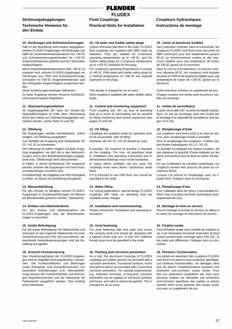
K481 DE/EN/FR 27
FLUDEXStrömungskupplungen Fluid Couplings Coupleurs hydrauliques
Technische Hinweise für Practical Hints for Installation Instructions de montageden Einbau
10. Dichtungen und SchmelzsicherungenFalls in der Bestellung nicht anders angegeben,werden FLUDEX-Kupplungen mit Dichtungen ausNBR für Dauerbetriebstemperaturen bis +85 5Cund Schmelzsicherungsschrauben für +135 5CAnsprechtemperatur geliefert (auf den Schraubeneingeschlagen).Wenn Dauerbetriebstemperaturen über +85 5C zuerwarten sind, müssen FLUDEX-Kupplungen mitDichtungen aus FKM und Schmelzsicherungs-schrauben für 160 5C Ansprechtemperatur (aufden Schrauben eingeschlagen) ausgerüstet wer-den.Diese Ausführungen bedingen Mehrpreis.Zu jeder Kupplung werden Reserve-Schmelzsi-cherungsschrauben mitgeliefert.
11. ÜberwachungseinheitenAb Kupplungsgröße 297 kann der Verlust derHydraulikflüssigkeit im Falle einer Überlastungdurch den Anbau von Überwachungsgeräten ver-mieden werden, (siehe Seite 24 und 25).
12. ÖlfüllungDie Kupplungen werden betriebsbereit, sofernmöglich, mit Ölfüllung ausgeliefert.Zum Befüllen der Kupplung sind Hydrauliköle VG22 / VG 32 zu verwenden.Die Füllmenge ist sofern möglich auf jeder Kupp-lung angegeben; sie darf die in den Maßzeich-nungen und in den Betriebsanleitungen angege-bene max. Ölfüllmenge nicht überschreiten.In Fällen, in denen synthetische Öle eingesetztwerden, müssen die Kupplungen mit Fluor-Kaut-schukdichtungen versehen sein.Ist beabsichtigt, die Kupplung mit HSD-Flüssigkeitzu füllen, ist dieses bei Bestellung anzugeben.
13. WasserbefüllungFür den Einsatz im Bergbau können FLUDEX-Kupplungen in Sonderausführungen mit Wasserals Betriebsmittel gefahren werden. (Mehrpreis).
14. Einbau und InbetriebnahmeFür den Einbau und Inbetriebnahme derFLUDEX-Kupplungen sind die Betriebsanlei-tungen zu beachten.
15. Axiale BefestigungFür die axiale Befestigung mit Haltescheibe undSchraube ist das tragende Wellenende mit einerZentrierbohrung nach DIN 332 auszuführen. Ab-weichende Gewindeabmessungen sind bei Be-stellung anzugeben.
16. Anstrich / KonservierungDas Aluminiumgehäuse der FLUDEX-Kupplun-gen wird im Regelfall nicht angestrichen / konser-viert. Die Funktionsflächen und Bohrungensowie Anbauteile sind kurzzeitkonserviert. Fürbesondere Anforderungen (z.B. Überseeliefe-rung) können die Funktionsflächen und Bohrun-gen langzeitkonserviert und die Anbauteile mitFarbanstrich ausgeführt werden. Dies bedingteinen Mehrpreis.
10. Oil seals and fusible safety plugsUnless otherwise specified in the order, FLUDEXfluid couplings are supplied with NBR seals asstandard. They are suitable for continuousoperating temperatures up to +85 5C, and thefusible safety plugs for a response temperatureup to +135 5C (stamped on the plug).For continuous operating temperatures in excessof +85 5C, FKM seals and fusible safety plugs fora melting temperature of +160 5C are required(stamped on the plug).
This design is charged for as an extra.Each coupling is supplied with spare fusible safetyplugs.
11. Control and monitoring equipmentFrom coupling size 297 up, loss of operatingfluid as a result of overloading can be avoidedby fitting monitoring and control equipment (seepages 24 and 25).
12. Oil fillingCouplings are supplied ready for operation and,as far as possible, with oil filling.Hydraulic oils VG 22 / VG 32 should be used.
If possible, the required oil quantity is stampedon the coupling. The max. oil quantities listedin Installation and operating instructions and indimensioned drawings must not be exceeded.In cases where synthetic oils are used, thecouplings must have fluoric caoutchouc sealsfitted.If it is intended to use HSD fluid, this should bespecified in the order.
13. Water fillingFor mining applications, special design FLUDEXcouplings with water as operating fluid areavailable (extra charge).
14. Installation and commissioningPlease consult the “Installation and operating in-structions”.
15. Axial fasteningFor axial fastening with end plate and screw,the carrying shaft end should be designed witha tapped centre hole acc. to DIN 332. Differentthread sizes must be specified in the order.
16. Painting and corrosion preventionAs a rule, the aluminium housings of FLUDEXcouplings are neither painted nor provided with acorrosion preventive. Functional surfaces, boresand add-on pieces are provided with a short-timecorrosion preventive. For special requirements,e.g. shipment overseas, a long-time corrosionpreventive can be applied to functional surfacesand bores, and add-on pieces be painted. This ischarged for as an extra.
10. Joints et bouchons fusiblesSauf indication contraire dans la commande, lescoupleurs FLUDEX sont livrés avec des joints enNBR convenant pour des températures jusqu’à85 5C en fonctionnement continu et des bou-chons fusibles pour une température de fusionde 135 5C (gravé sur le bouchon).Dans le cas où la température, en marche conti-nue, dépasse 85 5C, les coupleurs sont équipésde joints en FKM et de bouchons fusibles pour unetempérature de fusion de +160 5C (gravé sur lebouchon).
Cette exécution entraîne un supplément de prix.Chaque coupleur est vendu avec bouchons fusi-bles de rechange.
11. Unités de surveillanceA partir de la taille 297, la perte du liquide hydrau-lique, en cas de surcharge, peut être évitée parle montage d’un dispositif de surveillance (voir pa-ges 24 et 25).
12. Remplissage d’huileLes coupleurs sont livrés prêts à la mise en ser-vice, avec remplissage d’huile si possible.Pour le remplissage des coupleurs, n’utiliser quedes fluides hydrauliques VG 22 / VG 32.La quantité est indiquée sur chaque coupleur. Nepas dépasser la quantité d’huile indiquée sur lesplans d’encombrement et dans la notice d’entre-tien.En cas d’utilisation de lubrifiant synthétique, lescoupleurs doivent être pourvus de joints en ca-outchouc fluoré.Lorsque l’on prévoit le remplissage avec du li-quide HDS, l’indiquer dans la commande.
13. Remplissage d’eauPour l’utilisation dans les mines, il est possible d’u-tiliser l’eau à la place de fluide hydraulique (avecsupplément de prix).
14. Montage et mise en servicePour le montage et la mise en service, se référer àla notice de montage et instructions de service.
15. Fixation axialePour la fixation axiale avec rondelle de maintien etvis, il est nécessaire de prévoir l’exécution du boutd’arbre portant avec centrage selon DIN 332. Siles cotes sont différentes, l’indiquer dans la com-mande.
16. Peinture / ConservationLes carters en aluminium des coupleurs FLUDEXsont livrés non peint et sans protection spécifique.Les surfaces fonctionnelles, les alésages ainsique les pièces complémentaires reçoivent uneprotection anti-corrosion courte durée. Pourdes cas particuliers (expédition par mer) nouspouvons réaliser sur demande une protectionanti-corrosion spécifique des parties et piècesusinées ainsi q’une peinture des autres surfa-ces avec un supplément de prix.
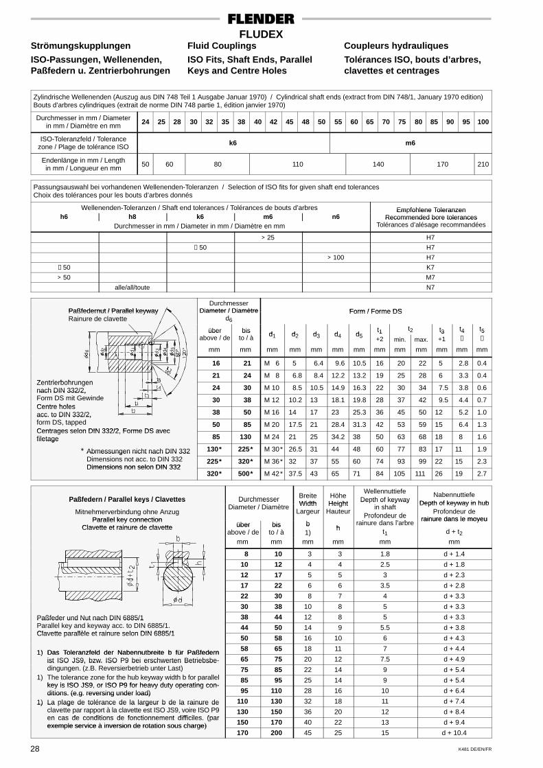
K481 DE/EN/FR28
FLUDEXStrömungskupplungen Fluid Couplings Coupleurs hydrauliques
ISO-Passungen, Wellenenden, ISO Fits, Shaft Ends, Parallel Tolérances ISO, bouts d’arbres,Paßfedern u. Zentrierbohrungen Keys and Centre Holes clavettes et centrages
Zylindrische Wellenenden (Auszug aus DIN 748 Teil 1 Ausgabe Januar 1970) / Cylindrical shaft ends (extract from DIN 748/1, January 1970 edition)Bouts d’arbres cylindriques (extrait de norme DIN 748 partie 1, édition janvier 1970)
Durchmesser in mm / Diameterin mm / Diamètre en mm 24 25 28 30 32 35 38 40 42 45 48 50 55 60 65 70 75 80 85 90 95 100
ISO-Toleranzfeld / Tolerancezone / Plage de tolérance ISO k6 m6
Endenlänge in mm / Lengthin mm / Longueur en mm 50 60 80 110 140 170 210
Passungsauswahl bei vorhandenen Wellenenden-Toleranzen / Selection of ISO fits for given shaft end tolerancesChoix des tolérances pour les bouts d’arbres donnés
Wellenenden-Toleranzen / Shaft end tolerances / Tolérances de bouts d’arbres Empfohlene Toleranzenh6 h8 k6 m6 n6
Em fohlene ToleranzenRecommended bore tolerances
Durchmesser in mm / Diameter in mm / Diamètre en mmRecommended bore tolerances
Tolérances d’alésage recommandées
> 25 H7
≤ 50 H7
> 100 H7
≤ 50 K7
> 50 M7
alle/all/toute N7
Paßfedernut / Parallel keywayDurchmesser
Diameter / Diamètre Form / Forme DSPaßfedernut / Parallel keywayRainure de clavette
Diameter / Diamètred6
Form / Forme DS
über bis d1 d2 d3 d4 d5t1 t2 t3 t4 t5über
above / debis
to / à d1 d2 d3 d4 d5t1+2 min. max.
t3+1
4
≈5
≈
mm mm mm mm mm mm mm mm mm mm mm mm mm
16 21 M 6 5 6.4 9.6 10.5 16 20 22 5 2.8 0.4
Zentrierbohrungen 21 24 M 8 6.8 8.4 12.2 13.2 19 25 28 6 3.3 0.4
Zentrierbohrungennach DIN 332/2, 24 30 M 10 8.5 10.5 14.9 16.3 22 30 34 7.5 3.8 0.6nach DIN 332/2,Form DS mit GewindeCentre holes
30 38 M 12 10.2 13 18.1 19.8 28 37 42 9.5 4.4 0.7Centre holesacc. to DIN 332/2, 38 50 M 16 14 17 23 25.3 36 45 50 12 5.2 1.0acc. to DIN 332/2,form DS, tappedCentrages selon DIN 332/2 Forme DS avec
50 85 M 20 17.5 21 28.4 31.3 42 53 59 15 6.4 1.3Centrages selon DIN 332/2, Forme DS avecfiletage 85 130 M 24 21 25 34.2 38 50 63 68 18 8 1.6filetage
* Abmessungen nicht nach DIN 332 130* 225* M 30* 26.5 31 44 48 60 77 83 17 11 1.9Abmessungen nicht nach DIN 332Dimensions not acc. to DIN 332Dimensions non selon DIN 332
225* 320* M 36* 32 37 55 60 74 93 99 22 15 2.3Dimensions non selon DIN 332
320* 500* M 42* 37.5 43 65 71 84 105 111 26 19 2.7
Paßfedern / Parallel keys / Clavettes Durchmesser BreiteWidth
HöheHeight
WellennuttiefeDepth of keyway
NabennuttiefeDepth of keyway in hubPaßfedern / Parallel keys / Clavettes
Mitnehmerverbindung ohne AnzugParallel key connection
DurchmesserDiameter / Diamètre Width
LargeurHeight
Hauteur
De th of keywayin shaft
Profondeur dei d l’ b
Depth of keyway in hubProfondeur de
rainure dans le moyeuParallel key connectionClavette et rainure de clavette über bis b
h
Profondeur derainure dans l’arbre
rainure dans le moyeuClavette et rainure de clavette über
above / debis
to / àb1)
h t1 d + t2mm mm mm mm mm mm
8 10 3 3 1.8 d + 1.4
10 12 4 4 2.5 d + 1.8
12 17 5 5 3 d + 2.3
17 22 6 6 3.5 d + 2.8
22 30 8 7 4 d + 3.3
30 38 10 8 5 d + 3.3
Paßfeder und Nut nach DIN 6885/1 38 44 12 8 5 d + 3.3Paßfeder und Nut nach DIN 6885/1Parallel key and keyway acc. to DIN 6885/1.Clavette parallèle et rainure selon DIN 6885/1
44 50 14 9 5.5 d + 3.8Clavette parallèle et rainure selon DIN 6885/1
50 58 16 10 6 d + 4.3
1) Das Toleranzfeld der Nabennutbreite b für Paßfedern 58 65 18 11 7 d + 4.41) Das Toleranzfeld der Nabennutbreite b für Paßfedernist ISO JS9, bzw. ISO P9 bei erschwerten Betriebsbe- 65 75 20 12 7.5 d + 4.9ist ISO JS9, bzw. ISO P9 bei erschwerten Betriebsbedingungen. (z.B. Reversierbetrieb unter Last)
1) Th t l f th h b k idth b f ll l 75 85 22 14 9 d + 5.4
1) The tolerance zone for the hub keyway width b for parallelkey is ISO JS9 or ISO P9 for heavy duty operating con-
85 95 25 14 9 d + 5.4key is ISO JS9, or ISO P9 for heavy duty operating con-ditions. (e.g. reversing under load) 95 110 28 16 10 d + 6.4ditions. (e.g. reversing under load)
1) La plage de tolérance de la largeur b de la rainure de 110 130 32 18 11 d + 7.41) La lage de tolérance de la largeur b de la rainure declavette par rapport à la clavette est ISO JS9, voire ISO P9en cas de conditions de fonctionnement difficiles (par
130 150 36 20 12 d + 8.4en cas de conditions de fonctionnement difficiles. (parexemple service à inversion de rotation sous charge) 150 170 40 22 13 d + 9.4exemple service à inversion de rotation sous charge)
170 200 45 25 15 d + 10.4
Adressen - DeutschlandA. FRIEDR. FLENDER AG - Postfach 1364, 46393 BocholtLieferanschrift: Alfred-Flender-Strasse 77, 46395 BocholtTel.: (0 28 71) 92 - 0; Fax: (0 28 71) 92 - 25 96E-mail: [email protected] � www.flender.com
–––––––––––––––––––––––––––––––––––––––––––––––––––––––––––––––––––––––A. FRIEDR. FLENDER AG Postfach 1364, 46393 BocholtKundenservice Center Nord Alfred-Flender-Strasse 77, 46395 Bocholt
Tel.: (0 28 71) 92 - 0; Fax: (0 28 71) 92 - 14 35E-mail: [email protected]
_______________________________________________________________________________________________________________________________________________
A. FRIEDR. FLENDER AG Postfach 1709, 72007 TübingenKundenservice Center Süd Bahnhofstrasse 40 - 44, 72072 Tübingen
Tel.: (0 70 71) 7 07 - 0; Fax: (0 70 71) 7 07 - 3 40E-mail: [email protected]
_______________________________________________________________________________________________________________________________________________
A. FRIEDR. FLENDER AG Liebigstrasse 14, 85757 Karlsfeld
Kundenservice Center Süd Tel.: (0 81 31) 90 03 - 0; Fax: (0 81 31) 90 03 - 33
Außenstelle München E-mail: [email protected]_______________________________________________________________________________________________________________________________________________
A. FRIEDR. FLENDER AG Schlossallee 8, 13156 Berlin
Kundenservice Center Ost / Osteuropa Tel.: (0 30) 91 42 50 58; Fax: (0 30) 47 48 79 30E-mail: [email protected]
–––––––––––––––––––––––––––––––––––––––––––––––––––––––––––––––––––––––A. FRIEDR. FLENDER AG Am Industriepark 2, 46562 VoerdeWerk Friedrichsfeld Tel.: (0 28 71) 92 - 0; Fax: (0 28 71) 92 - 25 96
E-mail: [email protected] � www.flender.com_______________________________________________________________________________________________________________________________________________
A. FRIEDR. FLENDER AG Postfach 44/45, 09320 PenigGetriebewerk Penig Thierbacher Strasse 24, 09322 Penig
Tel.: (03 73 81) 60; Fax: (03 73 81) 8 02 86E-mail: [email protected] � www.flender.com
_______________________________________________________________________________________________________________________________________________
A. FRIEDR. FLENDER AG Industriepark Bocholt, Schlavenhorst 100, 46395 BocholtKupplungswerk Mussum Tel.: (0 28 71) 92 - 28 68; Fax: (0 28 71) 92 - 25 79
E-mail: [email protected] � www.flender.com_______________________________________________________________________________________________________________________________________________
A. FRIEDR. FLENDER AG Obere Hauptstrasse 228 - 230, 09228 Chemnitz / WittgensdorfFLENDER GUSS Tel.: (0 37 22) 64 - 0; Fax: (0 37 22) 94 - 1 38
E-mail: [email protected] � www.flender-guss.de_______________________________________________________________________________________________________________________________________________
FLENDER SERVICE GMBH Postfach 101720, 44607 HerneSüdstrasse 111, 44625 HerneTel.: (0 23 23) 9 40 - 0; Fax: (0 23 23) 9 40 - 3 33E-mail: [email protected] � www.flender-service.com24h Service Hotline +49 (0) 17 22 81 01 00
_______________________________________________________________________________________________________________________________________________
WINERGY AG Postfach 201160, 46553 VoerdeAm Industriepark 2, 46562 VoerdeTel.: (0 28 71) 924; Fax: (0 28 71) 92 - 24 87E-mail: [email protected] � www.winergy-ag.com
_______________________________________________________________________________________________________________________________________________
FLENDER TÜBINGEN GMBH Postfach 1709, 72007 TübingenBahnhofstrasse 40 - 44, 72072 TübingenTel.: (0 70 71) 7 07 - 0; Fax: (0 70 71) 7 07 - 4 00E-mail: [email protected] � www.flender.com
_______________________________________________________________________________________________________________________________________________
LOHER GMBH Postfach 1164, 94095 RuhstorfHans-Loher-Strasse 32, 94099 RuhstorfTel.: (0 85 31) 3 90; Fax: (0 85 31) 3 94 37E-mail: [email protected] � www.loher.de

Addresses - InternationalE U R O P E
�������
Flender Ges.m.b.H.Industriezentrum Nö-SüdStrasse 4, Objekt 14Postfach 1322355 Wiener NeudorfPhone: +43 (0) 22 36 - 6 45 70Fax: +43 (0) 22 36 - 6 45 70 10E-mail: [email protected]
����� � � ���
����
N.V. Flender Belge S.A.Cyriel Buyssestraat 1301800 VilvoordePhone: +32 (0) 2 - 2 53 10 30Fax: +32 (0) 2 - 2 53 09 66E-mail: [email protected]
������
A. Friedr. Flender AGBranch Officec/o Auto - Profi GmbHAlabin Str. 52, 1000 SofiaPhone: +359 (0) 2 - 9 80 66 06Fax: +359 (0) 2 - 9 80 33 01E-mail: [email protected]
������� � �������
�����������������
A. Friedr. Flender AGBranch Officec/o HUM - Naklada d.o.o.Mandroviceva 310000 ZagrebPhone: +385 (0) 1 - 2 30 60 25Fax: +385 (0) 1 - 2 30 60 24E-mail: [email protected]
����� �������
A. Friedr. Flender AGBranch OfficeHotel DUO, Teplicka 1719000 Praha 9Phone: +420 2 - 83 88 23 00Fax: +420 2 - 83 88 22 05E-mail:[email protected]
�������
Flender Scandinavia A/SRugmarken 35 B3520 FarumPhone: +45 - 70 22 60 03Fax: +45 - 44 99 16 62E-mail: [email protected]
�������� � �����
��������
Flender Branch OfficeAddinol MineralölMarketing OÜSuur-Söjamäe 3211415 Tallinn / EsthoniaPhone: +372 (0) 6 - 27 99 99Fax: +372 (0) 6 - 27 99 90E-mail: [email protected]
������
Flender OyRuosilantie 2 B00390 HelsinkiPhone: +358 (0) 9 - 4 77 84 10Fax: +358 (0) 9 - 4 36 14 10E-mail: [email protected]
������
Flender S.a.r.l.3, rue Jean Monnet - B.P. 578996 Elancourt Cedex
Phone: +33 (0) 1 - 30 66 39 00Fax: +33 (0) 1 - 30 66 35 13E-mail: [email protected]
SALES OFFICE:Flender S.a.r.lAgence de LyonParc Inopolis, Route de Vourles69230 Saint Genis LavalPhone: +33 (0) 4 - 72 83 95 20Fax: +33 (0) 4 - 72 83 95 39E-mail: [email protected]
Flender-Graffenstaden SA1, rue du Vieux Moulin67400 Illkirch-GraffenstadenB.P. 8467402 Illkirch-GraffenstadenPhone: +33 (0) 3 - 88 67 60 00Fax: +33 (0) 3 - 88 67 06 17E-mail:[email protected]
�����
Flender Hellas Ltd.2, Delfon str., 11146 AthensPhone: +30 210 - 2 91 72 80Fax: +30 210 - 2 91 71 02E-mail: [email protected]
������
A. Friedr. Flender AGBranch OfficeBécsi Út 3 - 5, 1023 BudapestPhone: +36 (0) 1 - 3 45 07 90Fax: +36 (0) 1 - 3 45 07 92E-mail:[email protected]
����
Flender Cigala S.p.A.Parco Tecnologico ManzoniPalazzina GViale delle industrie, 1720040 Caponago (MI)Phone: +39 (0) 02 - 95 96 31Fax: +39 (0) 02 - 95 74 39 30E-mail: [email protected]
��� ����������
Flender Nederland B.V.Lage Brink 5 - 77317 BD ApeldoornPostbus 10737301 BH ApeldoornPhone: +31 (0) 55 - 5 27 50 00Fax: +31 (0) 55 - 5 21 80 11E-mail: [email protected]
Bruinhof B.V.Boterdiep 373077 AW RotterdamPostbus 96073007 AP RotterdamPhone: +31 (0) 10 - 4 97 08 08Fax: +31 (0) 10 - 4 82 43 50E-mail: [email protected]
������
Please refer toFlender Scandinavia A/SRugmarken 35 B3520 FarumPhone: +45 - 70 22 60 03Fax: +45 - 44 99 16 62E-mail: [email protected]
�����
A. Friedr. Flender AGBranch OfficePrzedstawicielstwo w Polsceul. Wyzwolenia 2743 - 190 Mikolów
Phone: +48 (0) 32 - 2 26 45 61Fax: +48 (0) 32 - 2 26 45 62E-mail: [email protected]
������
Rodamientos FEYC, S.A.R. Jaime Lopes Dias, 1668 CV1750 - 124 LissabonPhone: +351 (0) 21 7 54 24 10Fax: +351 (0) 21 7 54 24 19E-mail: [email protected]
�������
A. Friedr. Flender AGBranch OfficeB-dul Garii Obor Nr. 8DSector 2 - BucurestiPhone: +40 (0) 21 - 2 53 21 28Fax: +40 (0) 21 - 2 52 98 60E-mail: [email protected]
������
F & F GmbHTjuschina 4 - 6191119 St. PetersburgPhone: +7 (0) 812 - 3 20 90 34Fax: +7 (0) 812 - 3 20 90 82E-mail:[email protected]
�������
A. Friedr. Flender AGBranch OfficeVajanského 49P.O. Box 286, 08001 PresovPhone: +421 (0) 51 - 7 70 32 67Fax: +421 (0) 51 - 7 70 32 67E-mail:[email protected]
�����
Flender Ibérica S.A.Poligono Industrial San MarcosCalle Morse, 31 (Parcela D-15)28906 Getafe, MadridPhone: +34 (0) 91 - 6 83 61 86Fax: +34 (0) 91 - 6 83 46 50E-mail: [email protected]
������
Flender ScandinaviaÄsenvägen 244339 LerumPhone: +46 (0) 302 - 1 25 90Fax: +46 (0) 302 - 1 25 56E-mail: [email protected]
����������
Flender AGZeughausstr. 485600 LenzburgPhone: +41 (0) 62 - 8 85 76 00Fax: +41 (0) 62 - 8 85 76 76E-mail: [email protected]
������
Flender GücAktarma SistemleriSanayi ve Ticaret Ltd. Sti.IMES Sanayi, SitesiE Blok 502, Sokak No. 2281260 Dudullu - IstanbulPhone: +90 (0) 216 - 4 66 51 41Fax: +90 (0) 216 - 3 64 59 13E-mail: [email protected]
�������
A. Friedr. Flender AGBranch Officec/o DIV - Deutsche Industriever.Prospect Pobedy 4403057 KievPhone: +380 (0) 44 - 4 46 80 49Fax: +380 (0) 44 - 2 30 29 30E-mail: [email protected]
������ ������ � ����
Flender Power Transmission Ltd.Thornbury Works, Leeds RoadBradfordWest Yorkshire BD3 7EBPhone: +44 (0) 12 74 - 65 77 00Fax: +44 (0) 12 74 - 66 98 36E-mail:[email protected]
����������������
������ � ���������
A. Friedr. Flender AGBranch Officec/o G.P.Inzenjering d.o.o.III Bulevar 54 / 1911070 Novi BeogradPhone: +381 (0) 11 - 60 44 73Fax: +381 (0) 11 - 3 11 67 91E-mail: [email protected]
A F R I C A
����� �������
���������
Please refer to Flender s.a.r.l3, rue Jean Monnet - B.P. 578996 Elancourt CedexPhone: +33 (0) 1 - 30 66 39 00Fax: +33 (0) 1 - 30 66 35 13E-mail: [email protected]
����
Sons of Farid Hassanen81 Matbaa Ahlia StreetBoulac 11221, CairoPhone: +20 (0) 2 - 5 75 15 44Fax: +20 (0) 2 - 5 75 17 02E-mail: [email protected]
����� ������
Flender Power Transmission (Pty.) Ltd.Cnr. Furnace St & Quality Rd.P.O. Box 131, Isando 1600JohannesburgPhone: +27 (0) 11 - 5 71 20 00Fax: +27 (0) 11 - 3 92 24 34E-mail: [email protected]
SALES OFFICES:Flender Power Transmission (Pty.) Ltd.Unit 3 Marconi Park9 Marconi Crescent, MontagueGardens, P.O. Box 37291Chempet 7442, Cape TownPhone: +27 (0) 21 - 5 51 50 03Fax: +27 (0) 21 - 5 52 38 24E-mail: [email protected]
Flender Power Transmission (Pty.) Ltd.Unit 3 Goshawk ParkFalcon Industrial EstateP.O. Box 1608New Germany 3620, DurbanPhone: +27 (0) 31 - 7 05 38 92Fax: +27 (0) 31 - 7 05 38 72E-mail: [email protected]
Flender Power Transmission (Pty.) Ltd.9 Industrial Crescent, Ext. 25P.O. Box 17609, Witbank 1035Phone: +27 (0) 13 - 6 92 34 38Fax: +27 (0) 13 - 6 92 34 52E-mail: [email protected]
Flender Power Transmission (Pty.) Ltd.Unit 14 King Fisher Park, AltonCnr. Ceramic Curve & AluminaAllee, P.O. Box 101995Meerensee 3901Richards BayPhone: +27 (0) 35 - 7 51 15 63Fax: +27 (0) 35 - 7 51 15 64E-mail: [email protected]
A M E R I C A
��������
Chilicote S.A.Avda. Julio A. Roca 546C 1067 ABN Buenos AiresPhone: +54 (0) 11 - 43 31 66 10Fax: +54 (0) 11 - 43 31 42 78E-mail:[email protected]
�����
Flender Brasil Ltda.Rua Quatorze, 60Cidade Industrial32211 - 970, Contagem - MGPhone: +55 (0) 31 - 33 69 21 00Fax: +55 (0) 31 - 33 69 21 66E-mail:[email protected]
SALES OFFICES:Flender Brasil Ltda.Rua James Watt, 142conj. 142 - Brooklin Novo04576 - 050, São Paulo - SPPhone: +55 (0) 11 - 55 05 99 33Fax: +55 (0) 11 - 55 05 30 10E-mail: [email protected]
Flender Brasil Ltda.Rua Campos Salles, 1095sala 04 - Centro14015-110, Ribeirão Preto - SPPhone: +55 (0) 16 - 6 35 15 90Fax: +55 (0) 16 - 6 35 11 05E-mail:[email protected]
������
Flender Power Transmission Inc.215 Shields Court, Units 4 - 6Markham, Ontario L3R 8V2Phone: +1 (0) 9 05 - 3 05 10 21Fax: +1 (0) 9 05 - 3 05 10 23E-mail: [email protected]
���� � ��������
������ � �������
������� � ������
Flender Cono Sur LimitadaAvda. Galvarino Gallardo 1534Providencia, SantiagoPhone: +56 (0) 2 - 2 35 32 49Fax: +56 (0) 2 - 2 64 20 25E-mail: [email protected]
�������
A.G.P. Representaciones Ltda.Flender Liaison Office ColombiaAv Boyaca No 23A50 Bodega UA 7-1, BogotáPhone: +57 (0) 1 - 5 70 63 53Fax: +57 (0) 1 - 5 70 73 35E-mail: [email protected]
�� ���
Flender de Mexico S.A. de C.V.17, Pte, 713 Centro72000 PueblaPhone: +52 (0) 222 - 2 37 19 00Fax: +52 (0) 222 - 2 37 11 33E-mail:[email protected]
SALES OFFICES:Flender de Mexico S.A. de C.V.Lago Nargis No. 38Col. Granada11520 Mexico, D.F.Phone: +52 (0) 55 - 52 54 30 37Fax: +52 (0) 55 - 55 31 69 39E-mail:[email protected]
Flender de Mexico S.A. de C.V.Ave. San Pedro No. 231-5Col. Miravalle64660 Monterrey, N.L.Phone: +52 (0) 81 - 83 63 82 82Fax: +52 (0) 81 - 83 63 82 83E-mail:[email protected]
����
Potencia Industrial E.I.R.L.Calle Gonzales Olaechea110-URB, La AuroraMiraflores, LimaPhone: +51 (0) 1 - 2 42 84 68Fax: +51 (0) 1 - 2 42 08 62E-mail: [email protected]
���
Flender Corporation950 Tollgate RoadP.O. Box 1449Elgin, IL. 60123Phone: +1 (0) 8 47 - 9 31 19 90Fax: +1 (0) 8 47 - 9 31 07 11E-mail: [email protected]
Flender CorporationService Centers West4234 Foster Ave.Bakersfield, CA. 93308Phone: +1 (0) 6 61 - 3 25 44 78Fax: +1 (0) 6 61 - 3 25 44 70E-mail: [email protected]
�������
F. H. Transmisiones S.A.Urbanización Buena VistaCalle Johan Schafero Segunda CalleMunicipio Sucre, PetareCaracasPhone: +58 (0) 2 12 - 21 52 61Fax: +58 (0) 2 12 - 21 18 38E-mail: [email protected]
A S I A
����� ���
��� ����
Please refer to Flender LimitedNo. 2 St. George’s Gate Road5th Floor, HastingsKolkata - 700 022Phone: +91 (0) 33 - 2 23 05 45Fax: +91 (0) 33 - 2 23 18 57E-mail:[email protected]
������� ������� ��
�����
Flender Power Transmission (Tianjin) Co., Ltd.ShuangHu Rd. - ShuangchenRd. West, Beichen EconomicDevelopment Area (BEDA)Tianjin 300 400Phone: +86 (0) 22 - 26 97 20 63Fax: +86 (0) 22 - 26 97 20 61E-mail: [email protected]
Flender Power Transmission (Tianjin) Co., Ltd.Beijing OfficeC-415, Lufthansa Center50 Liangmaqiao Rd.Chaoyang DistrictBeijing 100 016
Phone: +86 (0) 10 - 64 62 21 51Fax: +86 (0) 10 - 64 62 21 43E-mail:[email protected]
Flender Power Transmission (Tianjin) Co., Ltd.Shanghai Office1101-1102 Harbour Ring Plaza18 Xizang Zhong Rd.Shanghai 200 001Phone: +86 (0) 21 - 53 85 31 48Fax: +86 (0) 21 - 53 85 31 46E-mail:[email protected]
Flender Power Transmission (Tianjin) Co., Ltd.Wuhan OfficeRm. 1503, Jianyin Building,709 JianshedadaoWuhan 430 015Phone: +86 (0) 27 - 85 48 67 15Fax: +86 (0) 27 - 85 48 68 36E-mail:[email protected]
Flender Power Transmission (Tianjin) Co., Ltd.Guangzhou OfficeRm. 2802, Guangzhou Inter-national Electronics Tower403 Huanshi Rd. EastGuangzhou 510 095Phone: +86 (0) 20 - 87 32 60 42Fax: +86 (0) 20 - 87 32 60 45E-mail:[email protected]
Flender Power Transmission (Tianjin) Co., Ltd.Chengdu OfficeG-6 / F, Guoxin Mansion,77 Xiyu StreetChengdu 610 015Phone: +86 (0) 28 - 86 19 83 72Fax: +86 (0) 28 - 86 19 88 10E-mail:[email protected]
Flender Power Transmission (Tianjin) Co., Ltd.Shenyang OfficeRm. 2-163, Tower I, City PlazaShenyang206 Nanjing Street (N), HepingDistrictShenyang 110 001Phone: +86 (0) 24 - 23 34 20 48Fax: +86 (0) 24 - 23 34 20 46E-mail:[email protected]
Flender Power Transmission (Tianjin) Co., Ltd.Xi’an OfficeRm. 302, Shanzi Zhong DaInternational Mansion30 Southern Rd.Xi’an 710 002Phone: +86 (0) 29 - 7 20 32 68Fax: +86 (0) 29 - 7 20 32 04E-mail:[email protected]
�� ��
Flender LimitedHead Office:No. 2 St. George’s Gate Road5th Floor, HastingsKolkata - 700 022Phone: +91 (0) 33 - 22 23 05 45Fax: +91 (0) 33 - 22 23 18 57E-mail:[email protected]
Flender LimitedIndustrial Growth CentreRakhajungle, NimpuraKharagpur - 721 302Phone: +91 (0) 3222 - 23 33 07Fax: +91 (0) 3222 - 23 33 64E-mail:[email protected]
SALES OFFICES:Flender LimitedEastern Regional Sales OfficeNo. 2 St. George’s Gate Road5th Floor, HastingsKolkata - 700 022Phone: +91 (0) 33 - 22 23 05 45Fax: +91 (0) 33 - 22 23 08 30E-mail: [email protected]
Flender LimitedWestern Regional Sales OfficePlot No. 23, Sector 19 - C,VashiNavi Mumbai - 400 705Phone: +91 (0) 22 - 27 65 72 27Fax: +91 (0) 22 - 27 65 72 28E-mail: [email protected]
Flender LimitedSouthern Regional Sales Office41 Nelson Manickam RoadAminjikaraiChennai - 600 029Phone: +91 (0) 44 - 23 74 39 21Fax: +91 (0) 44 - 23 74 39 19E-mail: [email protected]
Flender LimitedNorthern Regional Sales Office209-A, Masjid Moth, 2nd Floor(Behind South Extension II)New Delhi - 110 049Phone: +91 (0) 11 - 26 25 02 21Fax: +91 (0) 11 - 26 25 63 72E-mail: [email protected]
�� ������
Flender Singapore Pte. Ltd.Representative Office06 - 01 Wisma PresisiTaman Aries Blok A1 No.1Jakarta Barat 11620Phone: +62 (0) 21 - 58 90 20 15Fax: +62 (0) 21 - 58 90 20 19E-mail: [email protected]
����
Cimaghand Co. Ltd.P.O. Box 15745-493No. 13, 16th East StreetBeyhaghi Ave.,Argentina SquareTehran 15156Phone: +98 (0) 21 - 8 73 02 14Fax: +98 (0) 21 - 8 73 39 70E-mail: [email protected]
�����
Greenshpon EngineeringWorks Ltd.Bar-Lev Industrial ParkMisgav 20179Phone: +972 (0) 4 - 9 91 31 81Fax: +972 (0) 4 - 9 91 34 77E-mail:[email protected]
�����
Flender Japan Co., Ltd.WBG Marive East 21FNakase 2 - 6Mihama-ku, Chiba-shiChiba 261-7121Phone: +81 (0) 43 - 2 13 39 30Fax: +81 (0) 43 - 2 13 39 55E-mail:[email protected]
���������
A. Friedr. Flender AGBranch OfficeAbay ave 143, 480009 AlmatyPhone: +7 (0) 32 72 43 39 54Fax: +7 (0) 32 72 77 90 82E-mail: [email protected]
�����
Flender Ltd.7th Fl. Dorim Bldg.1823 Bangbae-DongSeocho-Ku, Seoul 137-060
Phone: +82 (0) 2 - 34 78 63 37Fax: +82 (0) 2 - 34 78 63 45E-mail:[email protected]
������
South Gulf CompanyAl-Showaikh Ind. AreaB.O. Box 26229Safat 13123Phone: +965 (0) - 4 82 97 15Fax: +965 (0) - 4 82 97 20E-mail:[email protected]
������
Gabriel Acar & Fils s.a.r.l.Dahr-el-JamalZone Industrielle, Sin-el-FilB.P. 80484, BeyrouthPhone: +961 (0) 1 - 49 82 72Fax: +961 (0) 1 - 49 49 71E-mail: [email protected]
�������
Flender Singapore Pte. Ltd.Representative Office37 A - 2, Jalan PJU 1/39Dataran Prima47301 Petaling JayaSelangor Darul EhsanPhone: +60 (0) 3 - 78 80 42 63Fax: +60 (0) 3 - 78 80 42 73E-mail: [email protected]
��������
Please refer toA. Friedr. Flender AG46393 BocholtPhone: +49 (0) 28 71 - 92 22 59Fax: +49 (0) 28 71 - 92 15 16E-mail:[email protected]
����������
Flender Singapore Pte. Ltd.Representative Office28/F, Unit 2814The Enterprise Centre6766 Ayala Avenue cornerPaseo de Roxas, Makati CityPhone: +63 (0) 2 - 8 49 39 93Fax: +63 (0) 2 - 8 49 39 17E-mail: [email protected]
������� � ���� � ��� ��
���� � ���� � �����
������ � �����
Please refer toA. Friedr. Flender AGMiddle East Sales OfficeIMES Sanayi SitesiE Blok 502, Sokak No. 2281260 Dudullu-IstanbulPhone: +90 (0) 216 - 4 99 66 23Fax: +90 (0) 2 16 - 3 64 59 13E-mail: [email protected]
��� � ������
South Gulf Sands Est.Bandaria Area, Dohan Bldg.,Flat 3/1P.O. Box 32150Al-Khobar 31952Phone: +966 (0) 50 - 8 87 53 32Fax: +966 (0) 3 - 8 87 53 31E-mail:[email protected]
���������
Flender Singapore Pte. Ltd.13 A, Tech Park CrescentSingapore 637843Phone: +65 (0) - 68 97 94 66Fax: +65 (0) - 68 97 94 11E-mail:[email protected]
�����
Misrabi Co & TradingMezzeh AutostradeTransportationBuilding 4/A, 5th FloorB.P. Box 12450, DamascusPhone: +963 (0) 11 - 6 11 67 94Fax: +963 (0) 11 - 6 11 09 08E-mail:[email protected]
������
A. Friedr. Flender AGTaiwan Branch Company1F, No. 5, Lane 240Nan Yang Street, HsichihTaipei Hsien 221Phone: +886 (0) 2 - 26 93 24 41Fax: +886 (0) 2 - 26 94 36 11E-mail:[email protected]
������
Flender Singapore Pte. Ltd.Representative OfficeTalay-Thong Tower, 56 Moo 910th floor room 1001Sukhumvit Rd. TungsuklaSriracha Chonburi 20230Phone: +66 (0) 38 - 49 51 66 - 8Fax: +66 (0) 38 - 49 51 69E-mail: [email protected]
�������
Flender Singapore Pte. Ltd.Representative OfficeSuite 6/6A, 16F Saigon Tower29 Le Duan Street, District 1Ho Chi Minh City, VietnamPhone: +84 (0) 8 - 8 23 62 97Fax: +84 (0) 8 - 8 23 62 88E-mail:[email protected]
A U S T R A L I A
Flender (Australia) Pty. Ltd.9 Nello Place, P.O. Box 6047Wetherill ParkN.S.W. 2164, SydneyPhone: +61 (0) 2 - 97 56 23 22Fax: +61 (0) 2 - 97 56 48 92E-mail: [email protected]
SALES OFFICES:Flender (Australia) Pty. Ltd.Suite 3, 261 Centre Rd.BentleighVIC 3204, MelbournePhone: +61 (0) 3 - 95 57 08 11Fax: +61 (0) 3 - 95 57 08 22E-mail: [email protected]
Flender (Australia) Pty. Ltd.Suite 5, 1407 Logan Rd.Mt. GravattQLD 4122, BrisbanePhone: +61 (0) 7 - 34 22 23 89Fax: +61 (0) 7 - 34 22 24 03E-mail: [email protected]
Flender (Australia) Pty. Ltd.Suite 2403 Great Eastern HighwayW.A. 6104, Redcliffe - PerthPhone: +61 (0) 8 - 94 77 41 66Fax: +61 (0) 8 - 94 77 65 11E-mail: [email protected]
��� ����
Please refer toFlender (Australia) Pty. Ltd.9 Nello Place, P.O. Box 6047Wetherill ParkN.S.W. 2164, SydneyPhone: +61 (0) 2 - 97 56 23 22Fax: +61 (0) 2 - 97 56 48 92E-mail: [email protected]

A. Friedr. Flender AG · Alfred-Flender-Strasse 77 · 46395 BocholtPhone: +49(0)2871-920 · Fax: +49(0)2871-922596 · www.flender.comK
481
DE
/EN
/FR
200
4-04
Mechanische und elektrische Antriebstechnik Mechanical and Electrical Power Transmission Equipment Equipements mécaniques et électriques pourtransmission de puissance