Embed Size (px)
Citation preview

Adafruit 16-channel PWM/Servo ShieldCreated by lady ada
Last updated on 2014-09-08 06:15:09 AM EDT
235
131313131415161819212121212223232323232323232325
Guide Contents
Guide ContentsOverviewAssemblyShield ConnectionsPins UsedConnecting other I2C devicesPowering Servos / PWM
Adding a Capacitor to the thru-hole capacitor slotConnecting a ServoAdding More Servos
Stacking ShieldsAddressing the Shields
Using the Adafruit LibraryDownload the library from GithubTest with the Example Code:Calibrating your ServosConverting from Degrees to Pulse Length
Library ReferencesetPWMFreq(freq)
DescriptionArgumentsExample
setPWM(channel, on, off)DescriptionArgumentsExample
FAQ
© Adafruit Industries https://learn.adafruit.com/adafruit-16-channel-pwm-slash-servo-shield Page 2 of 25

Overview
Driving servo motors with the Arduino Servo library is pretty easy, but each one consumes aprecious pin - not to mention some Arduino processing power. The Adafruit 16-Channel 12-bit PWM/Servo Driver Shield will drive up to 16 servos over I2C with only 2 pins. The on-boardPWM controller will drive all 16 channels simultaneously with no additional Arduino processingoverhead. What's more, you can stack up to 62 of them to control up to 992 servos - all withthe same 2 pins!
The Adafruit PWM/Servo Driver is the perfect solution for any project that requires a lot ofservos!
© Adafruit Industries https://learn.adafruit.com/adafruit-16-channel-pwm-slash-servo-shield Page 3 of 25

© Adafruit Industries https://learn.adafruit.com/adafruit-16-channel-pwm-slash-servo-shield Page 4 of 25
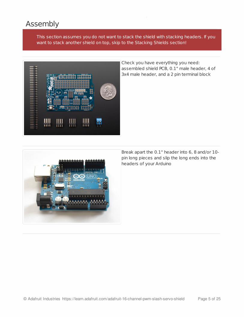
Assembly
Check you have everything you need:assembled shield PCB, 0.1" male header, 4 of3x4 male header, and a 2 pin terminal block
Break apart the 0.1" header into 6, 8 and/or 10-pin long pieces and slip the long ends into theheaders of your Arduino
This section assumes you do not want to stack the shield with stacking headers. If youwant to stack another shield on top, skip to the Stacking Shields section!
© Adafruit Industries https://learn.adafruit.com/adafruit-16-channel-pwm-slash-servo-shield Page 5 of 25

Place the shield on top of the header pins, theyshould fit into each of the holes along the edge
© Adafruit Industries https://learn.adafruit.com/adafruit-16-channel-pwm-slash-servo-shield Page 6 of 25

Solder each of the pins to secure the shield tothe headers
© Adafruit Industries https://learn.adafruit.com/adafruit-16-channel-pwm-slash-servo-shield Page 7 of 25

Place the 2 pin terminal block so it faces out.Also place the 3x4 headers so the short pinsare plugged into the shield and the long pinsare sticking up
To keep them in place, a few pieces of tape willhold them for when you flip the board over.
© Adafruit Industries https://learn.adafruit.com/adafruit-16-channel-pwm-slash-servo-shield Page 8 of 25
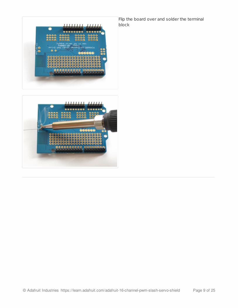
Flip the board over and solder the terminalblock
© Adafruit Industries https://learn.adafruit.com/adafruit-16-channel-pwm-slash-servo-shield Page 9 of 25

Then solder one pin of each 3x4 header to tackthem in place.
© Adafruit Industries https://learn.adafruit.com/adafruit-16-channel-pwm-slash-servo-shield Page 10 of 25
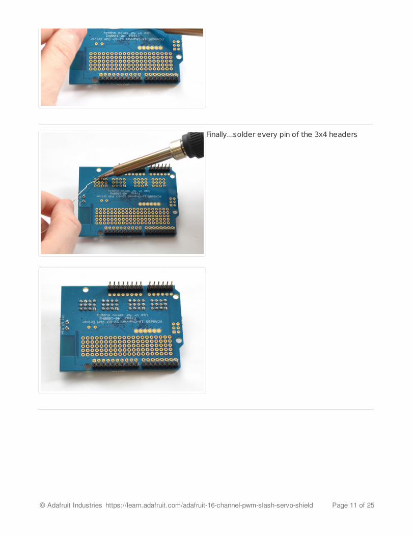
Finally...solder every pin of the 3x4 headers
© Adafruit Industries https://learn.adafruit.com/adafruit-16-channel-pwm-slash-servo-shield Page 11 of 25

You're done! Go onto the next sections to learnhow to use your servo/pwm shield
© Adafruit Industries https://learn.adafruit.com/adafruit-16-channel-pwm-slash-servo-shield Page 12 of 25

Shield ConnectionsPins UsedThe shield plugs in directly into any shield-compatible Arduino such as Duemilanove,Diecimila, UNO, Leonardo, Mega R3+, ADK R3+. The only pins required to run are theGround, 5V and SDA + SCL I2C control pins.
For backwards compatibility with old Ardunos, SCL is connected to A5 and SDA isconnected to A4. UNOs already have this connection on board. If you are using a Leonardoor Mega and want to use the A4/A5 pins, cut the traces on the top of the board between A4and A5 and the two pins next to them labeled SCL/SDA.
If you are using a Mega or ADK R2 or earlier, you will have to solder a wire from SCL to D21and SDA to D20
Connecting other I2C devicesSince I2C is a 'shared bus' you can still connect other I2C devices to the SDA/SCL pins aslong as they do not have a conflicting address. The default address for the shield is address0x40
Powering Servos / PWMThis shield has two power supplies. One is VCC - that is the 5V power from the Arduino, it isused to power the PWM chip and determines the I2C logic level and the PWM signal logiclevel. When this power supply is working you will see a red LED. The red LED must be litfor the Arduino & shield to work! Plug in the Arduino to USB or a wall adapter toprovide it.
© Adafruit Industries https://learn.adafruit.com/adafruit-16-channel-pwm-slash-servo-shield Page 13 of 25

To power servos you will need to also connect the V+ power supply - this isthe power supply for the servos. (If you are lighting up single LEDs you may not need thispower supply.) This power supply should be 5 or 6VDC. You can connect this power throughthe blue terminal block. There is reverse-polarity protection in case you hook up powerbackwards.
Nearly all servos are designed to run on about 5 or 6v. Keep in mind that a lot of servosmoving at the same time (particularly large powerful ones) will need a lot of current. Evenmicro servos will draw several hundred mA when moving. Some High-torque servoswill draw more than 1A each under load.
Good power choices are:
5v 2A switching power supply (http://adafru.it/276) (up to perhaps 4 servos)5v 10A switching power supply (http://adafru.it/658) (up to perhaps 16 servos)4xAA Battery Holder (http://adafru.it/830) - 6v with Alkaline cells. 4.8v with NiMHrechargeable cells, portable!4.8 or 6v Rechargeable RC battery packs from a hobby store.
Adding a Capacitor to the thru-hole capacitor slotWe have a spot on the PCB for soldering in an electrolytic capacitor. Based on your usage,you may or may not need a capacitor. If you are driving a lot of servos from a power supplythat dips a lot when the servos move, n * 100uF where n is the number of servos is agood place to start - eg 470uF or more for 5 servos. Since its so dependent on servocurrent draw, the torque on each motor, and what power supply, there is no "one magiccapacitor value" we can suggest which is why we don't include a capacitor in the kit.
SERVOS CAN USE A LOT OF POWER! It is not a good idea to use the Arduino 5v pin topower your servos. Electrical noise and 'brownouts' from excess current draw cancause your Arduino to act erratically, reset and/or overheat.
© Adafruit Industries https://learn.adafruit.com/adafruit-16-channel-pwm-slash-servo-shield Page 14 of 25

Connecting a ServoMost servos come with a standard 3-pin female connector that will plug directly into theheaders on the Servo Driver. Be sure to align the plug with the ground wire (usually black orbrown) with the bottom row and the signal wire (usually yellow or white) on the top.
© Adafruit Industries https://learn.adafruit.com/adafruit-16-channel-pwm-slash-servo-shield Page 15 of 25

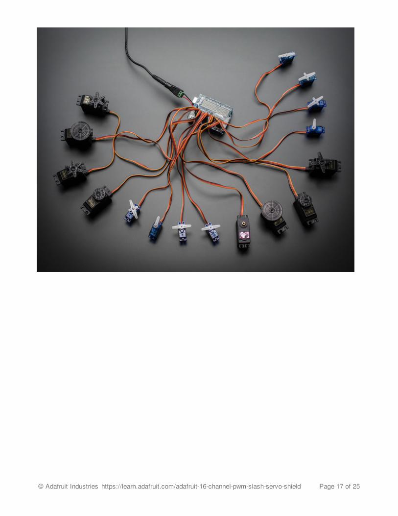
Adding More ServosUp to 16 servos can be attached to one board. If you need to control more than 16 servos,additional boards can be stacked as described on the next page.
© Adafruit Industries https://learn.adafruit.com/adafruit-16-channel-pwm-slash-servo-shield Page 16 of 25
© Adafruit Industries https://learn.adafruit.com/adafruit-16-channel-pwm-slash-servo-shield Page 17 of 25

Stacking ShieldsIf you want to plug shields on top of this one, make sure you pick up a set of shield-stackingheaders http://www.adafruit.com/product/85 (http://adafru.it/dij)and solder them instead of the male header
Since this shield only uses the I2C pins and the I2C bus is sharable, you can stack multipleshields on top of each other. You will need to have installed stacking headers & right angle3x4 connections for it to physically connect. Multiple shields (up to 62!) can be stacked tocontrol still more servos.
© Adafruit Industries https://learn.adafruit.com/adafruit-16-channel-pwm-slash-servo-shield Page 18 of 25

Addressing the ShieldsEach board in the chain must be assigned a unique address. This is done with the addressjumpers on the upper right edge of the board. The I2C base address for each board is 0x40.The binary address that you program with the address jumpers is added to the base I2Caddress.
To program the address offset, use a drop of solder to bridge the corresponding addressjumper for each binary '1' in the address.
© Adafruit Industries https://learn.adafruit.com/adafruit-16-channel-pwm-slash-servo-shield Page 19 of 25

Board 0: Address = 0x40 Offset = binary 00000 (no jumpers required)Board 1: Address = 0x41 Offset = binary 00001 (bridge A0 as in the photo above)Board 2: Address = 0x42 Offset = binary 00010 (bridge A1)Board 3: Address = 0x43 Offset = binary 00011 (bridge A0 & A1)Board 4: Address = 0x44 Offset = binary 00100 (bridge A2)
etc.
© Adafruit Industries https://learn.adafruit.com/adafruit-16-channel-pwm-slash-servo-shield Page 20 of 25

Using the Adafruit Library
Download the library from GithubStart by downloading the library from https://github.com/adafruit/Adafruit-PWM-Servo-Driver-Library (http://adafru.it/aQl)- you can just click the button below
Copy the zip file to the Libraries folder inside your Arduino Sketchbook folder and re-name itto Adafruit_PWMServoDriver. For more details on how to install Arduino libraries, check outour detailed tutorial! (http://adafru.it/aYM)
Download Adafruit PWM/ServoLibrary
http://adafru.it/cDw
Test with the Example Code:First make sure all copies of the Arduino are closed.
Next open a new copy of the IDE and select File->Examples->Adafruit_PWMServoDriver->Servo . This will open the example file in an IDE window.
Plug the shield into your Arduino, and a servo into the left-most 'port' as shown on theprevious page and upload the example code. Don't forget you will also have to provide 5Vto the V+ terminal block. Both red and green LEDs must be lit.
You should see the servo sweep back and forth over approximately 180 degrees.
Calibrating your ServosServo pulse timing varies between different brands and models. Since it is an analog controlcircuit, there is often some variation between samples of the same brand and model. Forprecise position control, you will want to calibrate the minumum and maximum pulse-widthsin your code to match known positions of the servo.
Find the MInimum:Using the example code, edit SERVOMIN until the low-point of the sweep reaches theminimum range of travel. It is best to approach this gradually and stop before the physicallimit of travel is reached.
Find the Maximum:Again using the example code, edit SERVOMAX until the high-point of the sweep reachesthe maximum range of travel. Again, is best to approach this gradually and stop before thephysical limit of travel is reached.
© Adafruit Industries https://learn.adafruit.com/adafruit-16-channel-pwm-slash-servo-shield Page 21 of 25

Converting from Degrees to Pulse LengthThe Arduino "map()" function (http://adafru.it/aQm) is an easy way to convert betweendegrees of rotation and your calibrated SERVOMIN and SERVOMAX pulse lengths. Assuminga typical servo with 180 degrees of rotation; once you have calibrated SERVOMIN to the 0-degree position and SERVOMAX to the 180 degree position, you can convert any anglebetween 0 and 180 degrees to the corresponding pulse length with the following line ofcode:
Use caution when adjusting SERVOMIN and SERVOMAX. Hitting the physical limits oftravel can strip the gears and permanently damage your servo.
pulselength = map(degrees, 0, 180, SERVOMIN, SERVOMAX);
© Adafruit Industries https://learn.adafruit.com/adafruit-16-channel-pwm-slash-servo-shield Page 22 of 25
Library ReferencesetPWMFreq(freq)
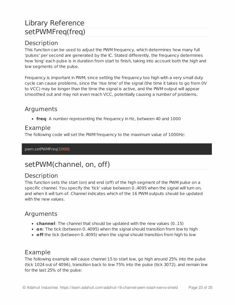
DescriptionThis function can be used to adjust the PWM frequency, which determines how many full'pulses' per second are generated by the IC. Stated differently, the frequency determineshow 'long' each pulse is in duration from start to finish, taking into account both the high andlow segments of the pulse.
Frequency is important in PWM, since setting the frequency too high with a very small dutycycle can cause problems, since the 'rise time' of the signal (the time it takes to go from 0Vto VCC) may be longer than the time the signal is active, and the PWM output will appearsmoothed out and may not even reach VCC, potentially causing a number of problems.
Arguments
freq: A number representing the frequency in Hz, between 40 and 1000
ExampleThe following code will set the PWM frequency to the maximum value of 1000Hz:
setPWM(channel, on, off)
DescriptionThis function sets the start (on) and end (off) of the high segment of the PWM pulse on aspecific channel. You specify the 'tick' value between 0..4095 when the signal will turn on,and when it will turn of. Channel indicates which of the 16 PWM outputs should be updatedwith the new values.
Arguments
channel: The channel that should be updated with the new values (0..15)on: The tick (between 0..4095) when the signal should transition from low to highoff:the tick (between 0..4095) when the signal should transition from high to low
ExampleThe following example will cause channel 15 to start low, go high around 25% into the pulse(tick 1024 out of 4096), transition back to low 75% into the pulse (tick 3072), and remain lowfor the last 25% of the pulse:
pwm.setPWMFreq(1000)
© Adafruit Industries https://learn.adafruit.com/adafruit-16-channel-pwm-slash-servo-shield Page 23 of 25

pwm.setPWM(15, 1024, 3072)
© Adafruit Industries https://learn.adafruit.com/adafruit-16-channel-pwm-slash-servo-shield Page 24 of 25

FAQCan this shield be used for LEDs or just servos?It can be used for LEDs as well as any other PWM-able device!
I am having strange problems when combining this shield with the Adafruit LEDMatrix/7Seg BackpacksWe are not sure why this occurs but there is an address collision even though theaddress are different! Set the backpacks to address 0x71 or anything other than thedefault 0x70 to make the issue go away.
If I'm using it with LEDs I cant quite get the PWM to be totally off?If you want to turn the LEDs totally offuse setPWM(pin, 4096, 0); not setPWM(pin,4095, 0);
I can't get this to work with my 7-segment LED displayThe PCA9865 chip has an "All Call" address of 0x70. This is in addition to the configuredaddress. This will cause an address collision if used with any other chip addressed to0x70.
© Adafruit Industries Last Updated: 2014-09-08 06:15:10 AM EDT Page 25 of 25