Embed Size (px)
Citation preview
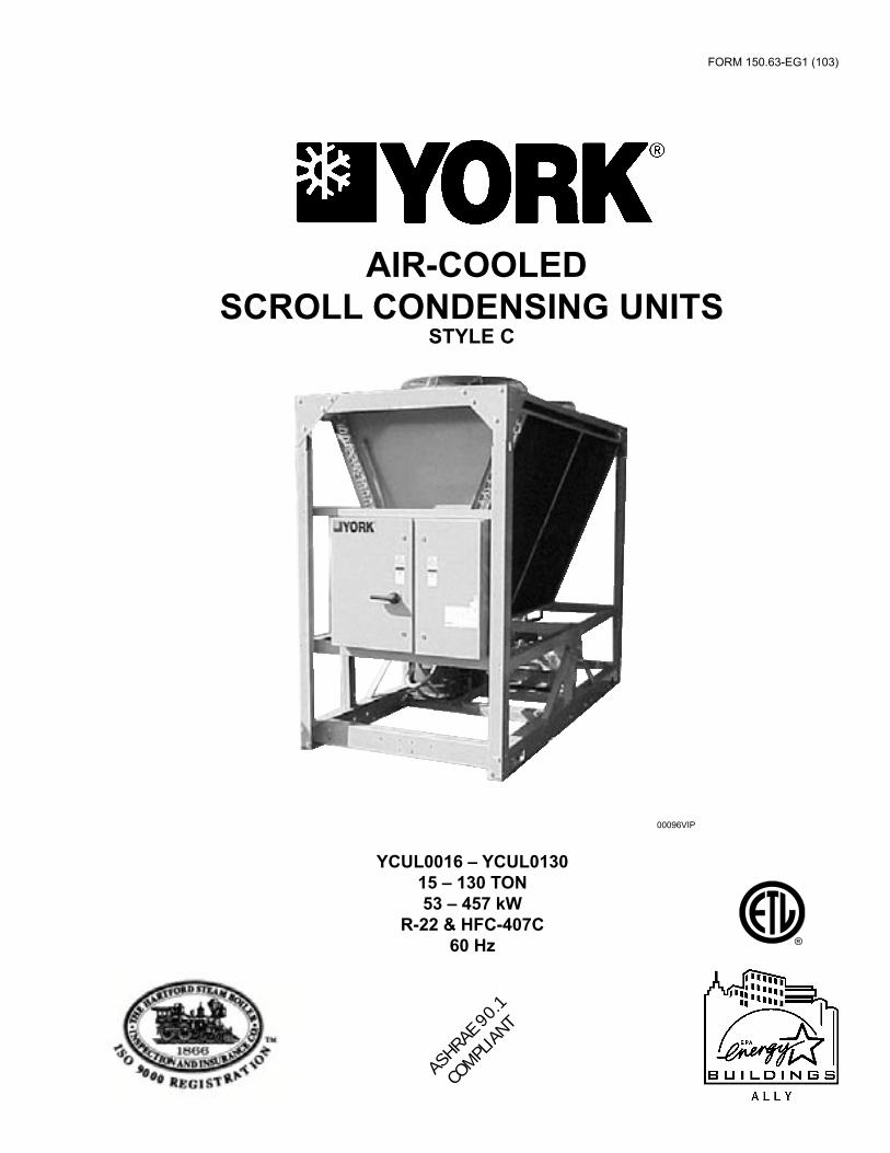
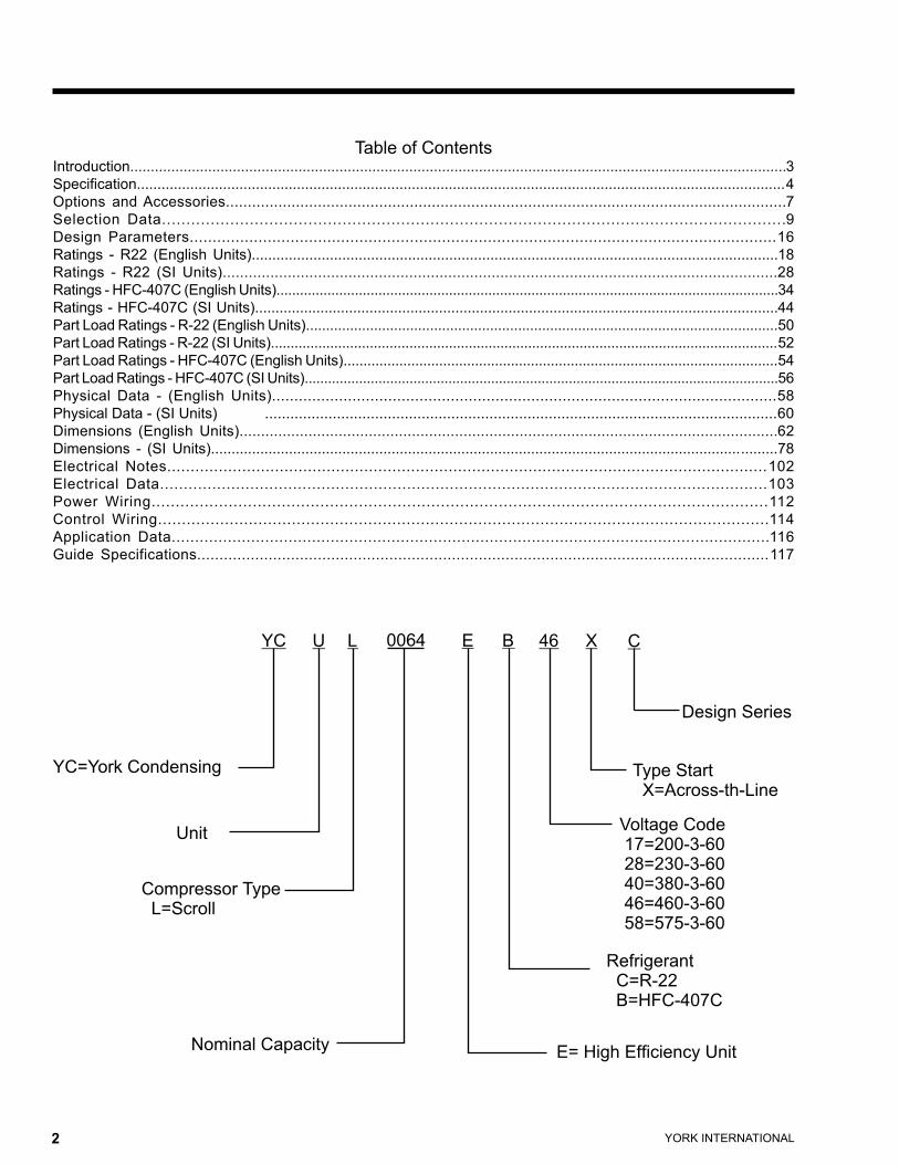
YCUL0016 – YCUL013015 – 130 TON53 – 457 kW
R-22 & HFC-407C60 Hz
FORM 150.63-EG1 (103)
AIR-COOLEDSCROLL CONDENSING UNITS
STYLE C
00096VIP
ASHRAE
90.
1
COMPL
IANT
YORK INTERNATIONAL2 YORK INTERNATIONAL 3
FORM 150.63-EG1
�� � � � � �� � �
������� ����������
����
���������� ������������
������� �������� �����������������������
���������������������������
������� �����������������������������������������������������������
���� ���������������������
������ ������
����
Table of ContentsIntroduction................................................................................................................................................................3Specification..............................................................................................................................................................4Options and Accessories................................................................................................................................7Selection Data................................................................................................................................9Design Parameters................................................................................................................................16Ratings - R22 (English Units)................................................................................................................................18Ratings - R22 (SI Units)................................................................................................................................28Ratings - HFC-407C (English Units)................................................................................................................................34Ratings - HFC-407C (SI Units)................................................................................................................................44Part Load Ratings - R-22 (English Units)......................................................................................................................50Part Load Ratings - R-22 (SI Units)................................................................................................................................52Part Load Ratings - HFC-407C (English Units).............................................................................................................54Part Load Ratings - HFC-407C (SI Units)..........................................................................................................................56Physical Data - (English Units).................................................................................................................58Physical Data - (SI Units) .........................................................................................................................60Dimensions (English Units).............................................................................................................................62Dimensions - (SI Units)..........................................................................................................................................78Electrical Notes................................................................................................................................102Electrical Data................................................................................................................................103Power Wiring................................................................................................................................112Control Wiring................................................................................................................................114Application Data................................................................................................................................116Guide Specifications................................................................................................................................117
YORK INTERNATIONAL2 YORK INTERNATIONAL 3
FORM 150.63-EG1
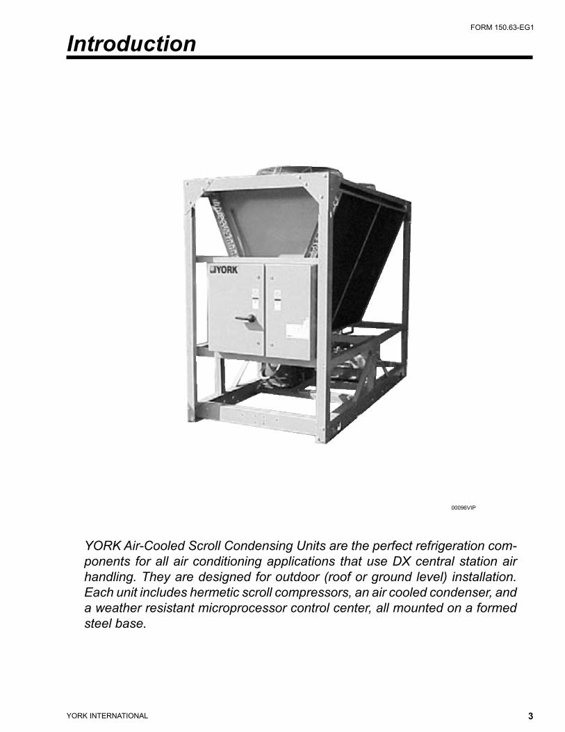
YORK Air-Cooled Scroll Condensing Units are the perfect refrigeration com-ponents for all air conditioning applications that use DX central station air handling. They are designed for outdoor (roof or ground level) installation. Each unit includes hermetic scroll compressors, an air cooled condenser, and a weather resistant microprocessor control center, all mounted on a formed steel base.
Introduction
00096VIP
YORK INTERNATIONAL4 YORK INTERNATIONAL 5
FORM 150.63-EG1
Specification
GENERAL
The 15 - 130 Ton (53 - 457 kW) YCUL Condensing Unit Models are shipped complete from the factory ready for field installation.
The unit is pressure-tested, evacuated and given a nitro-gen holding charge and includes an initial oil charge (R-22 or HFC-407C refringerant supplied by others). After assembly, a operational test is performed to assure that each control device operates correctly.
The unit structure is heavy-gauge, galvanized steel. This galvanized steel is coated with baked-on powder paint, which, when subjected to ASTM B117 500 hour, salt spray testing, yields a minimum ASTM 1654 rating of “6”. Units are designed in accordance with NFPA 70 (National Electric Code), ASHRAE/ANSI 15 Safety code for mechanical refrigeration, and are cETL listed. All units are produced at an ISO 9000-registered facility.
COMPRESSORS
The chiller has suction-gas cooled, hermetic, scroll compressors. The compressors incorporate a compli-ant scroll design in both the axial and radial direction. All rotating parts of the compressors are statically and dynamically balanced. A large internal volume and oil reservoir provides greater liquid tolerance. Compressor crankcase heaters are also included for extra protection against liquid migration.
CONDENSER
Coils – Fin and tube condenser coils of seamless, inter-nally-enhanced, high-condensing-coefficient, corrosion
resistant copper tubes are arranged in staggered rows, mechanically expanded into aluminum fins. Integral subcooling is included. The design working pressure of the coil is 450 PSIG (31 bar).
Fans – The condenser fans are composed of corrosion-resistant aluminum hub and glass-fiber-reinforced polypropylene composite blades molded into a low noise airfoil section. The are designed for maximum efficiency and are statically and dynamically balanced for vibration free operation. They are directly driven by independent motors, and positioned for vertical air discharge. The fan guards are constructed of heavy-gauge, rust-resistant, coated steel. All blades are statically and dynamically balanced for vibration-free operation.
Motors – The fan motors are Totally Enclosed Air-Over, squirrel-cage type, current protected. They feature ball bearings that are double-sealed and permanently lubricated.
REFRIGERANT CIRCUIT
One (YCUL0016-0040) or two (YCUL0046-0130) inde-pendent refrigerant circuits will be finished on each unit. All unit piping will be copper, with brazed joints. The liquid line will include a field connection shutoff valve with charging port located on each condenser circuit. Suc-tion line connections are provided on each refrigeration circuit. A filter drier and sight glass are shipped loose for field installation on each refrigerant circuit.
All expansion valves, liquid line solenoid valves, refriger-ant, and refrigerant field piping are supplied by others.
YORK INTERNATIONAL4 YORK INTERNATIONAL 5
FORM 150.63-EG1
MILLENNIUM CONTROL CENTER
All controls are contained in a NEMA 3R/12 (and equivalent to IP55*) cabinet with hinged outer door and includes:
Liquid Crystal Display with Light Emitting Diode backlighting for outdoor viewing: Two display lines Twenty characters per line
Color coded 12-button non-tactile keypad with sections for:
DISPLAY/PRINT of typical information: Suction temperatures (optional) Ambient temperature System pressures (each circuit) Operating hours and starts (each compressor) Print calls up to the liquid crystal display: Operating data for the systems History of fault shutdown data for up to the last six fault shutdown conditions
An RS-232 port, in conjunction with this press-to-print button, is provided to permit the capability of hard copy print-outs via a separate printer (by others).
ENTRY section to: ENTER setpoints or modify system values
SETPOINTS updating can be performed to: Suction pressure setting Suction pressure control zone Remote reset temperature range Set daily schedule/holiday for start/stop Manual override for servicing Low and high ambient cutouts Number of compressors Low suction pressure cutout High discharge pressure cutout Anti-recycle timer (compressor start cycle time) Anti-coincident timer (delay compressor starts)
UNIT section to: Set clock Set options • Set unit option • Set unit control for Discharge Air Temperature
Control or for Suction Pressure Control (requires Suction Pressure Transducers – standard on
YCUL 0076 - 0130 and optional on YCUL0016 - 0066.
UNIT ON/OFF switch
The microprocessor control center is capable of displaying the following:
• Suction temperatures (optional)• Low ambient temperature cutout setting• Outdoor air temperature• English or Metric data• Suction pressure cutout setting• Each system suction pressure (optional on 0016
- 0066 models and standard on 0076 - 0130 models)
• System discharge pressure (optional on 0016 - 0090 models and standard on 0096 - 0130 models)
• Discharge Air Temperature Reset via a YORK ISN DDC or Building Automation System (by others) via:
- a pulse width modulated (PWM) input as stan-dard
- a 4-20 milliamp or 0 -10 VDC input, or contact closure with the optional B.A.S. interface option• Anti-recycle timer status for each system• Anti-coincident system start timer condition• Compressor run status• No cooling load condition• Day, date and time• Daily start/stop times• Holiday status• Automatic or manual system lead/lag control
(Discharge Air Temperature control only)• Automatic lead/lag of compressors within a system• Compressor starts & operating hours (each compressor)• Status of hot gas valves, and fan operation• Run permissive status• Number of compressors running• Liquid solenoid valve status• Load & unload timer status
YORK INTERNATIONAL6 YORK INTERNATIONAL 7
FORM 150.63-EG1
Provisions are included for: pumpdown at shutdown; optional remote discharge air temperature reset and two steps of demand load limiting from an external building automation system. Unit alarm contacts are standard.
The operating program is stored in non-volatile memory (EPROM) to eliminate chiller failure due to AC powered failure/battery discharge. Programmed setpoints are retained in lithium battery-backed RTC memory for 5 years minimum.
POWER PANEL
Each panel contains:• Compressor power terminals• Compressor motor starting contactors per l.E.C.**• Control power terminals to accept incoming for 115-1-60 control power• Fan contactors & overload current protection
The power wiring is routed through liquid-tight conduit to the compressors and fans.
Specification
* Intensity of Protection European Standard** International Electrotechnical Commission
YORK INTERNATIONAL6 YORK INTERNATIONAL 7
FORM 150.63-EG1
Options and Accessories
POWER OPTIONS:
COMPRESSOR POWER CONNECTIONS – Single-point (YCUL0016-0040) or multiple-point (YCUL0046-0130) ter-minal block connection(s) are provided as standard. The following power connections are available as options. (See electrical data for specific voltage and options availability.) (Factory-mounted.)
SINGLE-POINT SUPPLY TERMINAL BLOCK – (Available on YCUL0046 - 0090 models (standard on YCUL0016 - 0040 models)). Includes enclosure, terminal-block and interconnecting wiring to the compressors. Separate external protection must be supplied, by others, in the incoming compressor-power wiring. (Do not include this option if either the Single-Point Non-Fused Disconnect Switch or Single-Point Circuit Breaker options have been included.)
SINGLE-POINT OR MULTIPLE-POINT SUPPLY TER-MINAL BLOCK(S) WITH INDIVIDUAL SYSTEM BREAK-ERS - (Available on YCUL0096-0130 models) Includes single- or dual-point terminal block connection(s) with factory interconnecting wiring from the terminal block to factory supplied system circuit breakers.
SINGLE-POINT NON-FUSED DISCONNECT SWITCH (Avail-able on YCUL0016-0090 models) OR MULTIPLE-POINT NON-FUSED DISCONNECT SWITCHES (Available on YCUL0096-0130 models) – Unit-mounted disconnect switch(es) with external, lockable handle (in compliance with Article 440-14 of N.E.C.), can be supplied to isolate the unit power voltage for servicing. Separate external fus-ing must be supplied, by others in the power wiring, which must comply with the National Electrical Code and/or local codes.
SINGLE-POINT NON-FUSED DISCONNECT SWITCH WITH INDIVIDUAL SYSTEM BREAKERS - (Available on YCUL0096-0130 models) Includes unit-mounted disconnect switch with external, lockable handles (in compliance with Article 440-14 of N.E.C.) to isolate unit power voltage for servicing. Factory interconnecting wiring is provided from the disconnect switch to factory supplied system circuit breakers.
SINGLE-POINT CIRCUIT BREAKER – (Available on YCUL0016-0090 models) – A unit mounted circuit breaker with external, lockable handle (in compliance with N.E.C. Article 440-14), can be supplied to isolate the power volt-age for servicing. (This option includes the Single-Point Power connection.)
CONTROL TRANSFORMER – Converts unit power voltage to 115-1-60 (0.5 or 1.0 kVA capacity). Factory mounting includes primary- and secondary-wiring between the transformer and
the control panel. (Factory-mounted.)
POWER FACTOR CORRECTION CAPACITORS – Will cor-rect unit compressor power factors to a 0.90-0.95. (Factory mounted).
CONTROL OPTIONS:
AMBIENT KIT (LOW) – (Available on YCUL0016-0090 models only [standard on YCUL0096-0130models]) Units will operate to 25°F (-4°C). This accessory includes all necessary compo-nents to permit condensing unit operation to 0°F (-18°C). (This option includes the Discharge Pressure Transducer / Readout Capability option.) For proper head pressure control in appli-cations below 25°F (-4°C) where wind gusts may exceed 5 mph, it is recommended that Optional Condenser Louvered Enclosure Panels also be included. (Factory-mounted.)
AMBIENT KIT (HIGH) – Required if units are to operate when the ambient temperature is above 115°F (46°C). Includes sun shield panels and discharge pressure transducers. (This option includes the Discharge Pressure Transducer / Readout Capa-bility option). (Field-mounted).
BUILDING AUTOMATION SYSTEM INTERFACE – The fac-tory addition of a Printed Circuit Board to accept a 4-20 mil-liamp, 0-10VDC or contact closure input to reset the discharge air temperature from a Building Automation System. (Only one of following options can be offered on a unit at a time: BAS, Remote Control Panel or Multi-unit Sequence Control). (Factory mounted). - (The standard unit capabilities include remote start-stop,
remote discharge air temperature reset via a PWM input signal or up to two steps of demand (load) limiting depend-ing on model.)
- (The standard control panel can be directly connected to a YORK Building Automated System via the standard on board RS485 communication port.)
LANGUAGE LCD AND KEYPAD DISPLAY – Spanish, French, German, and Italian unit LCD controls and keypad display available. Standard language is English.
DISCHARGE PRESSURE TRANSDUCERS AND READOUT CAPABILITY – (Available on YCUL0016 - 0090 models only [standard on YCUL0096 - 0130]) The addition of pressure transducers allows models to sense and display discharge pressure. (This option as included with either the low or high ambient kits). (Factory mounted).
SUCTION PRESSURE TRANSDUCERS AND READOUT CAPABILITY – (Available on YCUL0016-0066 models [stan-dard on YCUL0076-0130 models]). The addition of suction transducers allows models to sense and display suction pressure. This option is required for suction pressure control capability on YCUL0016-0066 models. (Factory mounted).
SUCTION TEMPERATURE READOUT – The addition of tem-perature sensors allow models to sense and display suction
YORK INTERNATIONAL8 YORK INTERNATIONAL 9
FORM 150.63-EG1
temperature. (Factory mounted).
MOTOR CURRENT MODULE – Capable of monitoring compressor motor current. Provides extra protection against compressor reverse rotation, phase-loss and phase imbalance. Option consists of one module per electrical system. (Fac-tory-mounted.)
REMOTE CONTROL PANEL AND WALL ADAPTOR–(Avail-able on the YCUL0016 - 0090 models only) (Only one of fol-lowing options can be offered on a unit at a time: BAS, Remote Control Panel, OptiView Remote Graphic Panel, or Multi-unit Sequence Control). (Field mounted).
OPTIVIEW REMOTE CONTROL PANEL - Graphical interface panel to remotely control and monitor up to 8 different units. (Refer to form 201.18-SG4 for detailed information)
COMPRESSOR AND PIPING OPTIONS:
CHICAGO CODE RELIEF VALVES – Unit will be provided with relief valves to meet Chicago code requirements. (Fac-tory-mounted).
HOT GAS BY-PASS – Permits continuous, stable operation at capacities below the minimum step of compressor unload-ing to as low as 5% capacity (depending on both the unit and operating conditions) by introducing an artificial load. Hot gas by-pass is available installed on refrigerant system #1 or on both systems of two circuited units. (Factory mounted).
SERVICE ISOLATION VALVE – Service suction and discharge (ball type) isolation valves are added to unit per system. This option also includes a system high pressure relief valve in compliance with ASHRAE 15. (Factory-mounted.)
CONDENSER AND CABINET OPTIONS:
Condenser coil protection against corrosive environments is available by choosing any of the following options. For addi-tional application recommendations, refer to FORM 150.12-ES1. (Factory-mounted).
PRE-COATED FIN CONDENSER COILS – The air-cooled condenser coils are constructed of black epoxy-coated aluminum fins. This can provide corro-sion resistance comparable to copper-fin coils in typical seashore locations. Either these or the post-coated coils (below), are recommended for units being installed at the seashore or where salt spray may hit the unit.
POST-COATED DIPPED CONDENSER COILS – The unit is built with dipped-cured condenser coils. This is another choice for seashore and other corrosive appli-cations (with the exception of strong alkalies, oxidizers and wet bromine, chlorine and fluorine in concentrations
greater than 100 ppm).
COPPER-FIN CONDENSER COILS – The unit constructed with condenser coils which have copper fins. (This is not recommended for units in areas where they may be exposed to acid rain).
ENCLOSURE PANELS (UNIT) – Tamperproof Enclosure Panels prevent unauthorized access to units. Enclosure Panels can provide an aesthetically pleasing alternative to expensive fencing. Additionally, for proper head pressure control, YORK recommends the use of Condenser Louvered Panels for winter applications where wind gustss may exceed five miles per hour. The following types of enclosure panels are available:
WIRE PANELS (Full Unit) – Consists of welded-wire-mesh guards mounted on the exterior of the unit. Prevents unauthorized access, yet provides free air flow. (Factory-mounted).
WIRE/LOUVERED PANELS – Consists of welded-wire-mesh panels on the bottom part of unit and louvered panels on the condenser section of the unit. (Factory-mounted).
LOUVERED PANELS (Condenser Coil Only) – Louvered panels are mounted on the sides and ends of the condenser coils for protection. (Factory-mounted).
LOUVERED PANELS (Full Unit) – Louvered panels sur-round the front, back, and sides of the unit. These prevent unauthorized access and visually screen unit components. Unrestricted air flow is permitted through generously sized louvered openings. This option is applicable for any outdoor design ambient temperature up to 115°F (46°C). (Factory-mounted).
SOUND ATTENUATION – One or both of the following sound attenuation options are recommended for residential or other similar sound sensitive locations:
COMPRESSOR ACOUSTIC SOUND BLANKET – Each compressor is individually enclosed by an acoustic sound blanket. The sound blankets are made with one layer of acoustical absorbent textile fiber of 5/8" (15mm) thickness; one layer of anti-vibrating heavy material thickness of 1/8" (3mm). Both are closed by two sheets of welded PVC, reinforced for temperature and UV resistance. (Factory-mounted).
LOW SOUND FANS – Lower RPM, 8-pole fan motors are used with steeper-pitch fans. (Factory-mounted).
VIBRATION ISOLATORS – Level adjusting, spring type 1" (25.4mm) or seismic deflection or neoprene pad isolators for mounting under unit base rails. (Field mounted).
Options and Accessories
YORK INTERNATIONAL8 YORK INTERNATIONAL 9
FORM 150.63-EG1
Selection Data
The ratings shown on pages 18 through 57 are based on unit operation in a well designed and properly piped system.
SELECTION RULES
1. Capabilities are based on Refrigerant 22 or 407C.2. Ratings may interpolated, but must not be extrapo-
lated.3. Ratings shown are at saturated suction temperatures
corresponding to pressures at the compressor. In actual practice, suction line pressure drop has the effect of reducing compressor capacity, forcing the compressor to operate at a lower suction pressure to maintain the desired evaporator temperature.
For normal air conditioning applications, size the suction line for a pressure drop of 3 PSI, corresponding to 2°F, for R-22 refrigerant. Thus, the evaporator temperature will be approximately 2°F higher than the compressor suction temperature. Line loss must be taken into consideration when selecting the evapora-tor.
SELECTION PROCEDURE
The air-cooled condensing unit may be selected from the Ratings on pages 20 through 48, if the ambient air temperature at the condenser and the saturated suction temperature at the compressor are known. The ambi-ent air temperature is a known design parameter, but the suction temperature at the compressor, in many cases, is known only within certain allowable limits. The actual compressor operating suction temperature and the overall performance of the system will depend directly upon the choice of the evaporator. Starting with a preliminary evaporator selection at a nominal evaporator temperature and using data supplied by the evaporator manufacturer, enter the ratings tables and select a unit to meet the required cooling load at a suction temperature at least 2°F below the evaporator temperature. The 2°F
allows for normal suction line loss.If more accurate selection is required, the evaporator capacity should be plotted against the condensing unit capacity to determine the balanced system performance. Again, it is necessary to factor in the suction line loss.
After the system balance point has been determined, the compressor KW input may be interpolated from the ratings tables.
SAMPLE SELECTION
Select an R-22 Air-Cooled Condensing Unit with a matched central station air handling unit having the following operating conditions:
Design Conditions1. An air handling unit with four large DX coils (two
per circuit) having a total cooling load of 600 MBH (50 tons).
2. The coil suction temperature required 45°F.3. The design outdoor ambient temperature is 90°F.4. The power supply is 460V/3 phase/60 HZ.
Selection1. Enter the YCUL 60 HZ Rating Table (page 20).2. The model YCUL0056EC will provide 51.3 tons with
48.3 compressor KW input at 90°F ambient air and 43°F suction pressure.
3. Calculate the compressor KW input for the specific design conditions of 50 tons and 90°F ambient air.
KW = 50tons
x 48.3 KW = 47.1 KW
51.3 tons
The YCUL0056EC is the suitable selection for the design capacity.

YORK INTERNATIONAL10 YORK INTERNATIONAL 11
FORM 150.63-EG1
Selection Data
REFRIGERANT PIPING
General – When the unit has been located in its final position, the unit piping may be connected. Normal instal-lation precautions should be observed in order to receive maximum operating efficiencies. System piping should conform to the York DX piping guide form 050.40-ES2 or ASHRAE refrigeration handbook guidelines. All piping design and installation is the responsibility of the user.
YORK ASSUMES NO WARRANTY RESPONSIBILITY FOR SYSTEM OPERATION OR FAILURES DUE TO IMPROPER PIPING OR PIPING DESIGN.
Filter driers and sight glasses are shipped loose for field installation on each refrigerant circuit. Field refrigerant piping can be connected to the condensing unit.
All expansion valves, liquid line solenoid valves, refrig-erant and refrigerant piping are supplied and installed by others.
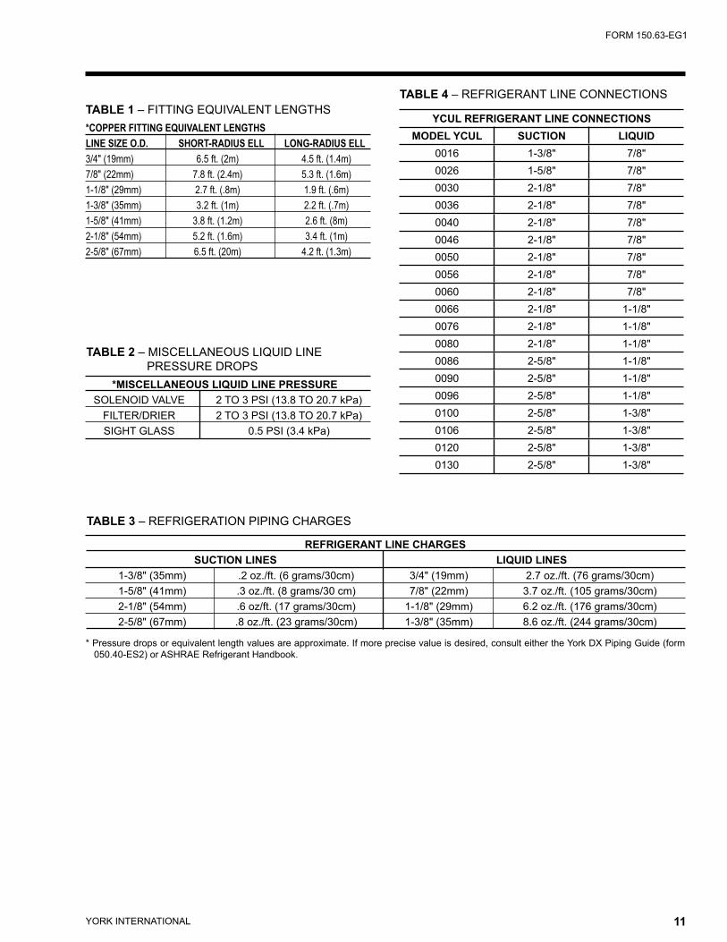
Table 4 lists refrigerant line connections sizes per unit model number.
REFRIGERANT LINE SIZING
Refrigerant piping systems must be designed to provide practical line sizes without excessive pressure drops, prevent compressor oil from being “trapped” in the refrig-erant piping, and ensure proper flow of liquid refrigerant to the thermal expansion valve. Considerations should be give to:
1) Suction line pressure drop due to refrigerant flow.2) Suction line refrigerant velocity for oil return.3) Liquid line pressure drop due to refrigerant flow.4) Liquid line pressure drop (or gain) due to vertical rise
of the liquid line.
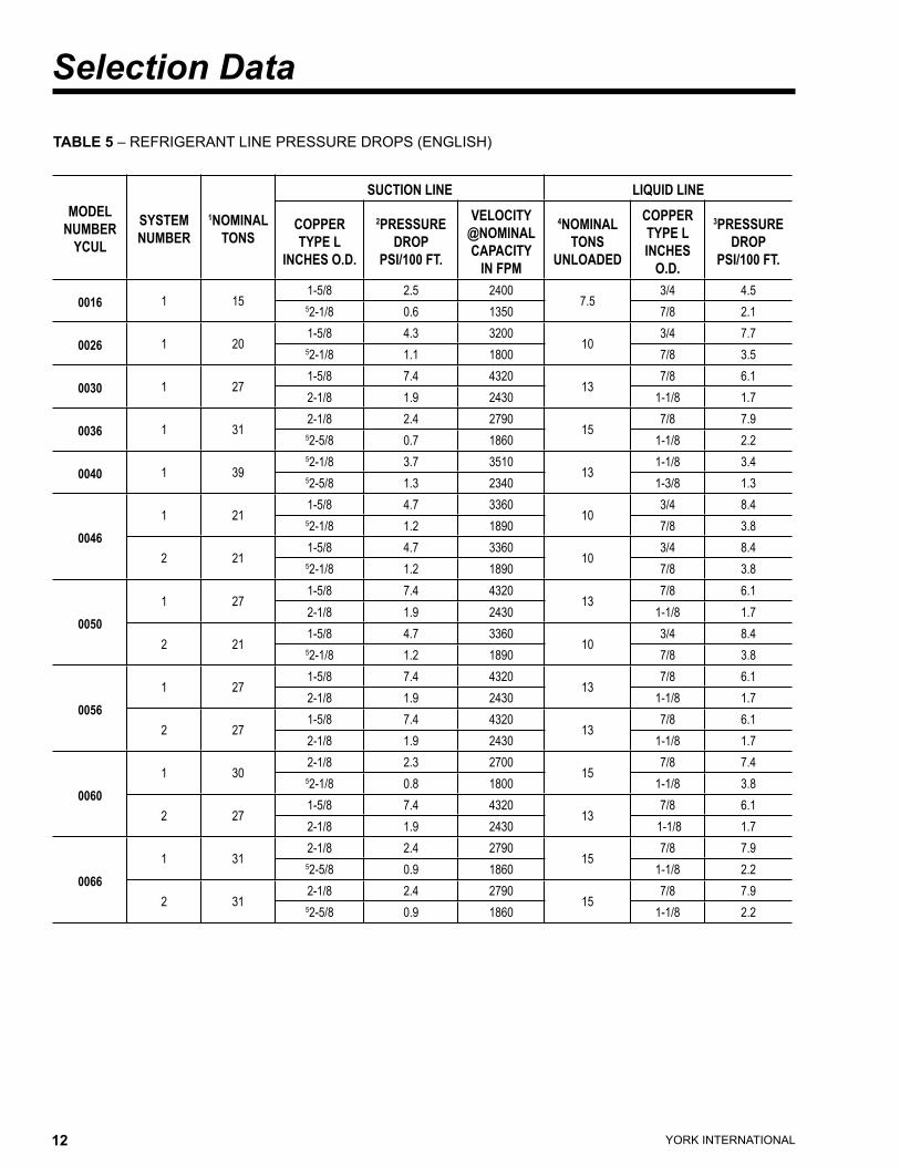
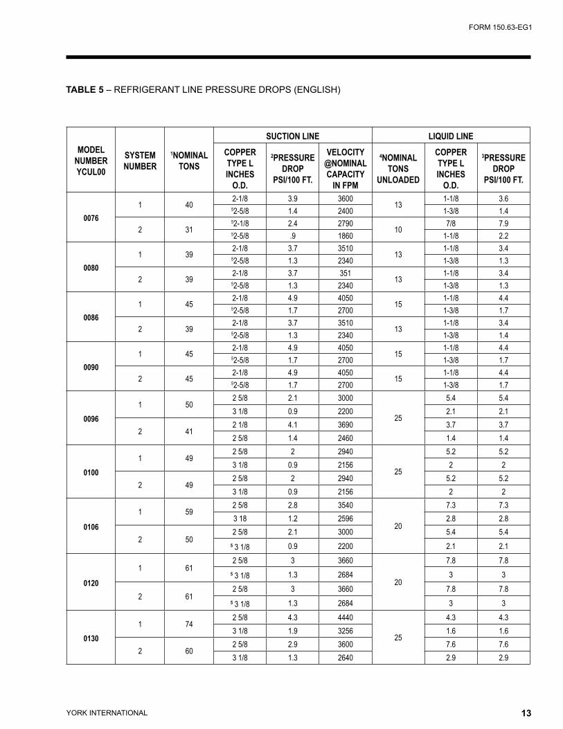
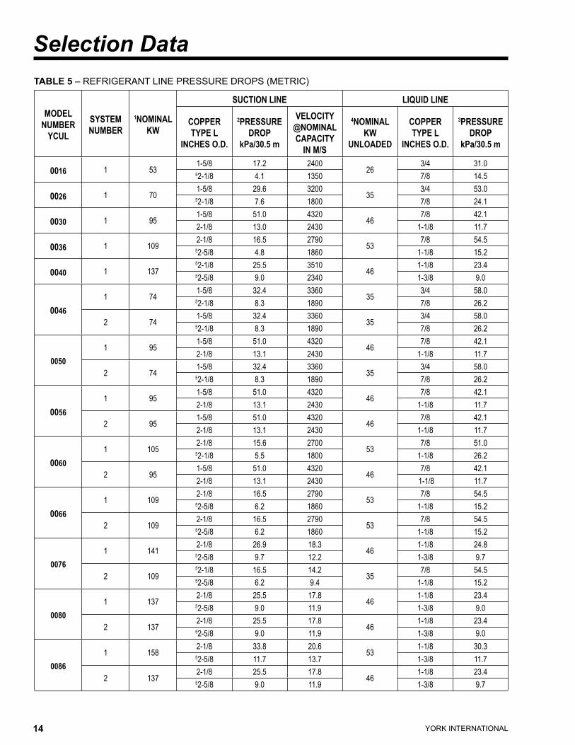
Table 5 provides the pressure drops for given pipe sizes for both liquid and suction lines. The pressure drops given are per 100 equivalent ft. (30.5 m) of refrigerant piping. These friction losses do not include any allow-ances for strainer, filter drier, solenoid valve, isolation valve or fittings
Nominal pressure drop for solenoids, sight glass, and driers are shown in Table 2.
Table 1 includes approximate equivalent lengths for copper fittings.
To ensure a solid column of liquid refrigerant to the expan-sion valve, the total liquid line pressure drop should
never exceed 40 psi (276 kPa). Refrigerant vapor in the liquid line will measurably reduce valve capacity and poor system performance can be expected.To allow adequate oil return to the compressor, suction risers should be sized for a minimum of 1000 FPM (5.08 m/s) while the system is operating at minimum capacity to ensure oil return up the suction riser. Refer to Table 5 under column labeled Nominal Tons (KW) Unloaded.
Evaporator Below Condensing Unit
On a system where the evaporator is located below the condensing unit, the suction line must be sized for both pressure drop and oil return. In some cases a double suction riser must be installed to ensure reliable oil return at reduced loads. Table 3 indicates when a double suc-tion riser should be used for listed pipe sizes to provide adequate oil return at reduced loads. The calculated information was based on maintaining a minimum of 1000 fpm (5.08 m/s) refrigerant vapor velocity.
Condenser Below Evaporator
When the condensing unit is located below the evapora-tor, the liquid line must be designed for both friction loss and static head loss due the vertical rise. The value of static head loss of 5 PSI/ft.(3.4 kPa/30 cm) must be added to the friction loss pressure drop in addition to all pressure drops due to driers, valves, etc.
OIL TRAPS
All horizontal suction lines should be pitched at least 1/4" per foot (2 cm/m) in the direction of the refrigerant flow to aid in the return of oil to the compressor. All suction lines with a vertical rise exceeding 3 feet (.91 meters) should have a “P” trap at the bottom and top of the riser. Suction lines with a vertical rise exceeding 25 feet (7.6 meters) should be trapped every 15 feet (4.6 meters).
REFRIGERANT CHARGE
The condensing unit is charged with a dry nitrogen hold-ing charge. The remaining operating charge for the con-densing unit, evaporator coil, and refrigerant piping must be weighed in after all refrigerant piping is installed, leak checked, and evacuated. Final adjustment of refrigerant charge should be verified by subcooling values (refer to section on Pre-Startup for checking subcooling).
REFRIGERANT PIPING REFERENCE
For more details, refer to ASHRAE Refrigeration Hand-book, Chapter 2.
YORK INTERNATIONAL10 YORK INTERNATIONAL 11
FORM 150.63-EG1
TABLE 1 – FITTING EQUIVALENT LENGTHS *COPPER FITTING EQUIVALENT LENGTHS LINE SIZE O.D. SHORT-RADIUS ELL LONG-RADIUS ELL 3/4" (19mm) 6.5 ft. (2m) 4.5 ft. (1.4m) 7/8" (22mm) 7.8 ft. (2.4m) 5.3 ft. (1.6m) 1-1/8" (29mm) 2.7 ft. (.8m) 1.9 ft. (.6m) 1-3/8" (35mm) 3.2 ft. (1m) 2.2 ft. (.7m) 1-5/8" (41mm) 3.8 ft. (1.2m) 2.6 ft. (8m) 2-1/8" (54mm) 5.2 ft. (1.6m) 3.4 ft. (1m) 2-5/8" (67mm) 6.5 ft. (20m) 4.2 ft. (1.3m)
TABLE 2 – MISCELLANEOUS LIQUID LINE PRESSURE DROPS *MISCELLANEOUS LIQUID LINE PRESSURE SOLENOID VALVE 2 TO 3 PSI (13.8 TO 20.7 kPa) FILTER/DRIER 2 TO 3 PSI (13.8 TO 20.7 kPa) SIGHT GLASS 0.5 PSI (3.4 kPa)
TABLE 4 – REFRIGERANT LINE CONNECTIONS
YCUL REFRIGERANT LINE CONNECTIONSMODEL YCUL SUCTION LIQUID
0016 1-3/8" 7/8"0026 1-5/8" 7/8"0030 2-1/8" 7/8"0036 2-1/8" 7/8"0040 2-1/8" 7/8"0046 2-1/8" 7/8"0050 2-1/8" 7/8"0056 2-1/8" 7/8"0060 2-1/8" 7/8"0066 2-1/8" 1-1/8"0076 2-1/8" 1-1/8"0080 2-1/8" 1-1/8"0086 2-5/8" 1-1/8"0090 2-5/8" 1-1/8"0096 2-5/8" 1-1/8"0100 2-5/8" 1-3/8"0106 2-5/8" 1-3/8"0120 2-5/8" 1-3/8"0130 2-5/8" 1-3/8"
TABLE 3 – REFRIGERATION PIPING CHARGES
REFRIGERANT LINE CHARGES SUCTION LINES LIQUID LINES 1-3/8" (35mm) .2 oz./ft. (6 grams/30cm) 3/4" (19mm) 2.7 oz./ft. (76 grams/30cm) 1-5/8" (41mm) .3 oz./ft. (8 grams/30 cm) 7/8" (22mm) 3.7 oz./ft. (105 grams/30cm) 2-1/8" (54mm) .6 oz/ft. (17 grams/30cm) 1-1/8" (29mm) 6.2 oz./ft. (176 grams/30cm) 2-5/8" (67mm) .8 oz./ft. (23 grams/30cm) 1-3/8" (35mm) 8.6 oz./ft. (244 grams/30cm)
* Pressure drops or equivalent length values are approximate. If more precise value is desired, consult either the York DX Piping Guide (form 050.40-ES2) or ASHRAE Refrigerant Handbook.
YORK INTERNATIONAL12 YORK INTERNATIONAL 13
FORM 150.63-EG1
TABLE 5 – REFRIGERANT LINE PRESSURE DROPS (ENGLISH)
MODEL NUMBER
YCUL
SYSTEMNUMBER
1NOMINALTONS
SUCTION LINE LIQUID LINE
COPPERTYPE L
INCHES O.D.
2PRESSUREDROP
PSI/100 FT.
VELOCITY @NOMINALCAPACITY
IN FPM
4NOMINALTONS
UNLOADED
COPPERTYPE LINCHES
O.D.
3PRESSUREDROP
PSI/100 FT.
0016 1 151-5/8 2.5 2400
7.53/4 4.5
52-1/8 0.6 1350 7/8 2.1
0026 1 201-5/8 4.3 3200
103/4 7.7
52-1/8 1.1 1800 7/8 3.5
0030 1 271-5/8 7.4 4320
137/8 6.1
2-1/8 1.9 2430 1-1/8 1.7
0036 1 312-1/8 2.4 2790
157/8 7.9
52-5/8 0.7 1860 1-1/8 2.2
0040 1 3952-1/8 3.7 3510
131-1/8 3.4
52-5/8 1.3 2340 1-3/8 1.3
00461 21
1-5/8 4.7 336010
3/4 8.452-1/8 1.2 1890 7/8 3.8
2 211-5/8 4.7 3360
103/4 8.4
52-1/8 1.2 1890 7/8 3.8
00501 27
1-5/8 7.4 432013
7/8 6.12-1/8 1.9 2430 1-1/8 1.7
2 211-5/8 4.7 3360
103/4 8.4
52-1/8 1.2 1890 7/8 3.8
00561 27
1-5/8 7.4 432013
7/8 6.12-1/8 1.9 2430 1-1/8 1.7
2 271-5/8 7.4 4320
137/8 6.1
2-1/8 1.9 2430 1-1/8 1.7
00601 30
2-1/8 2.3 270015
7/8 7.452-1/8 0.8 1800 1-1/8 3.8
2 271-5/8 7.4 4320
137/8 6.1
2-1/8 1.9 2430 1-1/8 1.7
00661 31
2-1/8 2.4 279015
7/8 7.952-5/8 0.9 1860 1-1/8 2.2
2 312-1/8 2.4 2790
157/8 7.9
52-5/8 0.9 1860 1-1/8 2.2
Selection Data
YORK INTERNATIONAL12 YORK INTERNATIONAL 13
FORM 150.63-EG1
TABLE 5 – REFRIGERANT LINE PRESSURE DROPS (ENGLISH)
MODEL NUMBERYCUL00
SYSTEMNUMBER
1NOMINALTONS
SUCTION LINE LIQUID LINECOPPERTYPE LINCHES
O.D.
2PRESSUREDROP
PSI/100 FT.
VELOCITY @NOMINALCAPACITY
IN FPM
4NOMINALTONS
UNLOADED
COPPERTYPE LINCHES
O.D.
3PRESSUREDROP
PSI/100 FT.
00761 40
2-1/8 3.9 360013
1-1/8 3.652-5/8 1.4 2400 1-3/8 1.4
2 3152-1/8 2.4 2790
107/8 7.9
52-5/8 .9 1860 1-1/8 2.2
00801 39
2-1/8 3.7 351013
1-1/8 3.452-5/8 1.3 2340 1-3/8 1.3
2 392-1/8 3.7 351
131-1/8 3.4
52-5/8 1.3 2340 1-3/8 1.3
00861 45
2-1/8 4.9 405015
1-1/8 4.452-5/8 1.7 2700 1-3/8 1.7
2 392-1/8 3.7 3510
131-1/8 3.4
52-5/8 1.3 2340 1-3/8 1.4
00901 45
2-1/8 4.9 405015
1-1/8 4.452-5/8 1.7 2700 1-3/8 1.7
2 452-1/8 4.9 4050
151-1/8 4.4
52-5/8 1.7 2700 1-3/8 1.7
00961 50
2 5/8 2.1 3000
25
5.4 5.43 1/8 0.9 2200 2.1 2.1
2 412 1/8 4.1 3690 3.7 3.72 5/8 1.4 2460 1.4 1.4
01001 49
2 5/8 2 2940
25
5.2 5.23 1/8 0.9 2156 2 2
2 492 5/8 2 2940 5.2 5.23 1/8 0.9 2156 2 2
0106
1 592 5/8 2.8 3540
20
7.3 7.33 18 1.2 2596 2.8 2.8
2 502 5/8 2.1 3000 5.4 5.4
5 3 1/8 0.9 2200 2.1 2.1
0120
1 612 5/8 3 3660
20
7.8 7.85 3 1/8 1.3 2684 3 3
2 612 5/8 3 3660 7.8 7.8
5 3 1/8 1.3 2684 3 3
01301 74
2 5/8 4.3 4440
25
4.3 4.33 1/8 1.9 3256 1.6 1.6
2 602 5/8 2.9 3600 7.6 7.63 1/8 1.3 2640 2.9 2.9
YORK INTERNATIONAL14 YORK INTERNATIONAL 15
FORM 150.63-EG1
TABLE 5 – REFRIGERANT LINE PRESSURE DROPS (METRIC)
MODEL NUMBER
YCUL
SYSTEMNUMBER
1NOMINALKW
SUCTION LINE LIQUID LINE
COPPERTYPE L
INCHES O.D.
2PRESSUREDROP
kPa/30.5 m
VELOCITY @NOMINALCAPACITY
IN M/S
4NOMINALKW
UNLOADED
COPPERTYPE L
INCHES O.D.
3PRESSUREDROP
kPa/30.5 m
0016 1 531-5/8 17.2 2400
263/4 31.0
52-1/8 4.1 1350 7/8 14.5
0026 1 701-5/8 29.6 3200
353/4 53.0
52-1/8 7.6 1800 7/8 24.1
0030 1 951-5/8 51.0 4320
467/8 42.1
2-1/8 13.0 2430 1-1/8 11.7
0036 1 1092-1/8 16.5 2790
537/8 54.5
52-5/8 4.8 1860 1-1/8 15.2
0040 1 13752-1/8 25.5 3510
461-1/8 23.4
52-5/8 9.0 2340 1-3/8 9.0
00461 74
1-5/8 32.4 336035
3/4 58.052-1/8 8.3 1890 7/8 26.2
2 741-5/8 32.4 3360
353/4 58.0
52-1/8 8.3 1890 7/8 26.2
00501 95
1-5/8 51.0 432046
7/8 42.12-1/8 13.1 2430 1-1/8 11.7
2 741-5/8 32.4 3360
353/4 58.0
52-1/8 8.3 1890 7/8 26.2
00561 95
1-5/8 51.0 432046
7/8 42.12-1/8 13.1 2430 1-1/8 11.7
2 951-5/8 51.0 4320
467/8 42.1
2-1/8 13.1 2430 1-1/8 11.7
00601 105
2-1/8 15.6 270053
7/8 51.052-1/8 5.5 1800 1-1/8 26.2
2 951-5/8 51.0 4320
467/8 42.1
2-1/8 13.1 2430 1-1/8 11.7
00661 109
2-1/8 16.5 279053
7/8 54.552-5/8 6.2 1860 1-1/8 15.2
2 1092-1/8 16.5 2790
537/8 54.5
52-5/8 6.2 1860 1-1/8 15.2
00761 141
2-1/8 26.9 18.346
1-1/8 24.852-5/8 9.7 12.2 1-3/8 9.7
2 10952-1/8 16.5 14.2
357/8 54.5
52-5/8 6.2 9.4 1-1/8 15.2
00801 137
2-1/8 25.5 17.846
1-1/8 23.452-5/8 9.0 11.9 1-3/8 9.0
2 1372-1/8 25.5 17.8
461-1/8 23.4
52-5/8 9.0 11.9 1-3/8 9.0
00861 158
2-1/8 33.8 20.653
1-1/8 30.352-5/8 11.7 13.7 1-3/8 11.7
2 1372-1/8 25.5 17.8
461-1/8 23.4
52-5/8 9.0 11.9 1-3/8 9.7
Selection Data

YORK INTERNATIONAL14 YORK INTERNATIONAL 15
FORM 150.63-EG1
TABLE 5 – REFRIGERANT LINE PRESSURE DROPS (METRIC)
MODEL NUMBER
YCUL
SYSTEMNUMBER
1NOMINALKW
SUCTION LINE LIQUID LINE
COPPERTYPE L
INCHES O.D.
2PRESSUREDROP
kPa/30.5 m
VELOCITY @NOMINALCAPACITY
IN M/S
4NOMINALKW
UNLOADED
COPPERTYPE L
INCHES O.D.
3PRESSUREDROP
kPa/30.5 m
00901 158
2-1/8 33.8 20.653
1-1/8 30.352-5/8 11.7 13.7 1-3/8 11.7
2 1582-1/8 33.8 20.6
531-1/8 30.3
52-5/8 11.7 13.8 1-3/8 11.7
00961 175.7
2 5/8 14.5 914
87.9
1 1/8 37.23 1/8 6.2 671 1 3/8 14.5
2 144.12 1/8 28.3 1125 1 1/8 25.52 5/8 9.7 750 1 3/8 9.7
01001 172.2
2 5/8 13.8 896
87.9
1 1/8 35.93 1/8 6.2 657 1 3/8 13.8
2 172.22 5/8 13.8 896 1 1/8 35.93 1/8 6.2 657 1 3/8 13.8
01061 207.4
2 5/8 19.3 1079
70.3
1 1/8 50.33 18 8.3 791 1 3/8 19.3
2 175.72 5/8 14.5 914 1 1/8 37.2
5 3 1/8 6.2 671 1 3/8 14.5
01201 214.4
2 5/8 20.7 1116
70.3
1 1/8 53.85 3 1/8 9.0 818 1 3/8 20.7
2 214.42 5/8 20.7 1116 1 1/8 53.8
5 3 1/8 9.0 818 1 3/8 20.7
01301 260.1
2 5/8 29.6 1353
87.9
1 3/8 29.63 1/8 13.1 992 1 5/8 11.0
2 210.92 5/8 20.0 1097 1 1/8 52.43 1/8 9.0 805 1 38 20.0
REFRIGERANT PIPING NOTES1. Based on R-22 at the nominal capacity of the unit or system, an ambient temperature of 95°F (35°C) and a suction temperature of 45°F
(7.2°C).2. Suction line sizes were calculated based on a nominal maximum pressure drop to 3 PSI/100 ft. (20.7 kPa/30.5 m). When calculating suction
line pressure drop for a specific application, it should be noted that system capacity decreases as suction line pressure drop increases.3. Liquid pressure drop (or gain) due to a vertical liquid line is not included in the tables and must be taken into account when determining pres-
sure drop (or gain) of the liquid line. The nominal value that must be included in the liquid line loss (or gain) is .5 PSI/foot (3.4 kPa/30 cm) of rise (or gain). To ensure a solid column of liquid refrigerant to the expansion valve, the total maximum pressure drop of the liquid line should not exceed 40 PSI (276 kPa) based on 15°F (8.3°C) subcooled liquid. Vapor in the liquid line, even in small amounts, will measurably reduce valve capacity and poor system performance will result. In addition, pressure loss for strainers, filter driers, solenoid valves, and isolation valve or fittings are not included in this table, and must be taken into account.
4. Nominal Tons (KW) Unloaded is based on one compressor (per system) operating at design conditions.5. Based on minimum compressor staging for the given pipe size, a double suction riser should be used to ensure proper oil return to the com-
pressor on all vertical suction risers. Oil returning up the riser moves up the inner surface of the pipe and depends on the mass velocity of the refrigerant vapor at the wall surface to move the oil up the vertical rise.
6. Hot gas bypass lines are typically 7/8" for lines up to 40 feet and 1-1/8" for lines over 40 feet in length (12 meters). The field connections sizes are 7/8" for the optional factory mounted hot gas bypass valve. Note: Hot gas bypass is only available for refrigerant system number 1.
7. For more information, please refer to either the York DX Piping Guide (form 050.40-ES2) or the ASHRAE Refrigertion Handbook.
YORK INTERNATIONAL16 YORK INTERNATIONAL 17
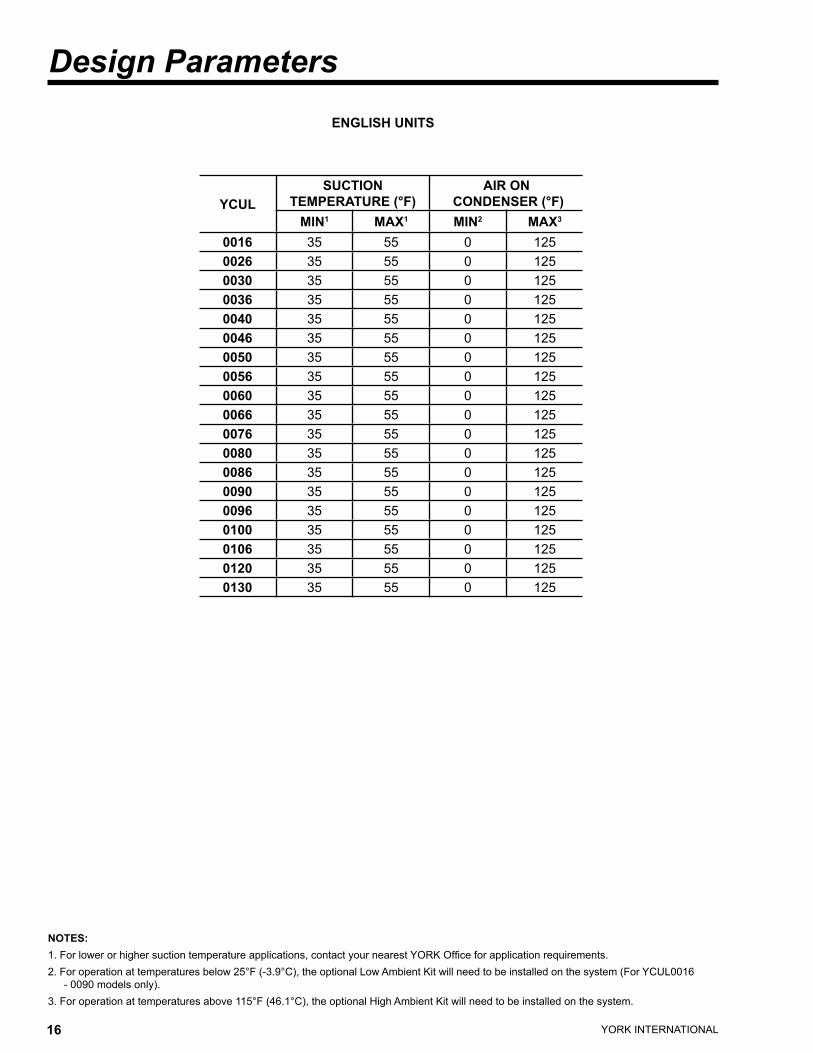
FORM 150.63-EG1
NOTES:1. For lower or higher suction temperature applications, contact your nearest YORK Office for application requirements.2. For operation at temperatures below 25°F (-3.9°C), the optional Low Ambient Kit will need to be installed on the system (For YCUL0016
- 0090 models only).3. For operation at temperatures above 115°F (46.1°C), the optional High Ambient Kit will need to be installed on the system.
ENGLISH UNITS
Design Parameters
YCULSUCTION
TEMPERATURE (°F)AIR ON
CONDENSER (°F)MIN1 MAX1 MIN2 MAX3
0016 35 55 0 1250026 35 55 0 1250030 35 55 0 1250036 35 55 0 1250040 35 55 0 1250046 35 55 0 1250050 35 55 0 1250056 35 55 0 1250060 35 55 0 1250066 35 55 0 1250076 35 55 0 1250080 35 55 0 1250086 35 55 0 1250090 35 55 0 1250096 35 55 0 1250100 35 55 0 1250106 35 55 0 1250120 35 55 0 1250130 35 55 0 125
YORK INTERNATIONAL16 YORK INTERNATIONAL 17
FORM 150.63-EG1
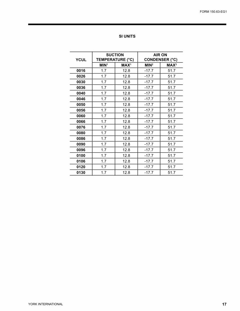
SI UNITS
YCULSUCTION
TEMPERATURE (°C)AIR ON
CONDENSER (°C)MIN1 MAX1 MIN2 MAX3
0016 1.7 12.8 -17.7 51.70026 1.7 12.8 -17.7 51.70030 1.7 12.8 -17.7 51.70036 1.7 12.8 -17.7 51.70040 1.7 12.8 -17.7 51.70046 1.7 12.8 -17.7 51.70050 1.7 12.8 -17.7 51.70056 1.7 12.8 -17.7 51.70060 1.7 12.8 -17.7 51.70066 1.7 12.8 -17.7 51.70076 1.7 12.8 -17.7 51.70080 1.7 12.8 -17.7 51.70086 1.7 12.8 -17.7 51.70090 1.7 12.8 -17.7 51.70096 1.7 12.8 -17.7 51.70100 1.7 12.8 -17.7 51.70106 1.7 12.8 -17.7 51.70120 1.7 12.8 -17.7 51.70130 1.7 12.8 -17.7 51.7
YORK INTERNATIONAL18 YORK INTERNATIONAL 19
FORM 150.63-EG1
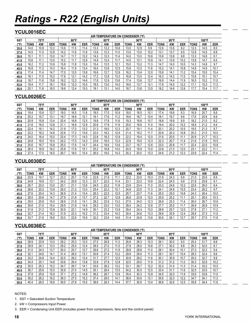
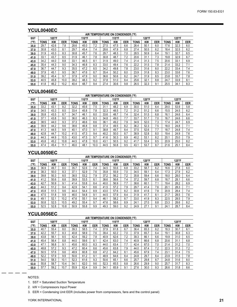
Ratings - R22 (English Units)
NOTES:1. SST = Saturated Suction Temperature2. kW = Compressors Input Power3. EER = Condensing Unit EER (includes power from compressors, fans and the control panel)
YCUL0016EC AIR TEMPERATURE ON CONDENSER (°F)
SST(°F)
75°F 80°F 85°F 90°F 95°F 100°FTONS KW EER TONS KW EER TONS KW EER TONS KW EER TONS KW EER TONS KW EER
35.0 14.0 10.9 12.2 13.6 11.5 11.4 13.3 12.2 10.6 13.0 12.9 9.9 12.6 13.6 9.2 12.3 14.5 8.537.0 14.5 11.0 12.6 14.2 11.6 11.8 13.8 12.3 11.0 13.5 13.0 10.2 13.1 13.7 9.5 12.8 14.5 8.839.0 15.1 11.1 13.0 14.7 11.7 12.2 14.3 12.3 11.4 14.0 13.0 10.6 13.6 13.8 9.8 13.3 14.6 9.141.0 15.6 11.1 13.5 15.2 11.7 12.6 14.9 12.4 11.7 14.5 13.1 10.9 14.1 13.9 10.2 13.8 14.7 9.443.0 16.2 11.2 13.9 15.8 11.8 13.0 15.4 12.5 12.1 15.0 13.2 11.3 14.7 14.0 10.5 14.3 14.8 9.745.0 16.8 11.3 14.3 16.4 11.9 13.4 16.0 12.6 12.5 15.6 13.3 11.6 15.2 14.1 10.8 14.8 14.9 10.147.0 17.4 11.4 14.7 17.0 12.0 13.8 16.6 12.7 12.9 16.2 13.4 12.0 15.8 14.1 11.2 15.4 15.0 10.449.0 18.1 11.5 15.2 17.6 12.1 14.2 17.2 12.8 13.3 16.8 13.5 12.4 16.3 14.2 11.5 15.9 15.1 10.751.0 18.7 11.6 15.6 18.2 12.2 14.6 17.8 12.9 13.6 17.4 13.6 12.7 16.9 14.4 11.9 16.5 15.2 11.053.0 19.4 11.7 16.1 18.9 12.3 15.0 18.5 13.0 14.0 18.0 13.7 13.1 17.6 14.5 12.2 17.1 15.3 11.355.0 20.1 11.8 16.5 19.6 12.4 15.5 19.1 13.1 14.5 18.7 13.8 13.5 18.2 14.6 12.6 17.7 15.4 11.7
YCUL0026EC AIR TEMPERATURE ON CONDENSER (°F)
SST(°F)
75°F 80°F 85°F 90°F 95°F 100°FTONS KW EER TONS KW EER TONS KW EER TONS KW EER TONS KW EER TONS KW EER
35.0 19.4 15.6 12.7 19.0 16.5 11.8 18.5 17.5 10.9 18.0 18.5 10.1 17.4 19.6 9.3 16.9 20.7 8.637.0 20.2 15.7 13.1 19.7 16.6 12.1 19.1 17.6 11.2 18.6 18.7 10.4 18.1 19.7 9.6 17.6 20.9 8.939.0 20.9 15.8 13.4 20.4 16.8 12.5 19.8 17.8 11.6 19.3 18.8 10.7 18.8 19.9 9.9 18.2 21.0 9.241.0 21.6 16.0 13.8 21.1 16.9 12.9 20.6 17.9 11.9 20.0 18.9 11.0 19.4 20.0 10.2 18.9 21.2 9.443.0 22.4 16.1 14.2 21.9 17.0 13.2 21.3 18.0 12.3 20.7 19.1 11.4 20.1 20.2 10.5 19.5 21.3 9.745.0 23.2 16.2 14.6 22.6 17.2 13.6 22.0 18.2 12.6 21.4 19.2 11.7 20.8 20.3 10.8 20.2 21.5 10.047.0 24.0 16.4 15.0 23.4 17.3 14.0 22.8 18.3 12.9 22.2 19.4 12.0 21.6 20.5 11.1 20.9 21.7 10.349.0 24.8 16.5 15.4 24.2 17.5 14.3 23.6 18.5 13.3 22.9 19.5 12.3 22.3 20.7 11.4 21.6 21.8 10.551.0 25.6 16.7 15.8 25.0 17.6 14.7 24.4 18.6 13.6 23.7 19.7 12.6 23.0 20.8 11.7 22.4 22.0 10.853.0 26.5 16.9 16.2 25.8 17.8 15.1 25.2 18.8 14.0 24.5 19.9 13.0 23.8 21.0 12.0 23.1 22.2 11.155.0 27.4 17.0 16.5 26.7 18.0 15.4 26.0 19.0 14.3 25.3 20.0 13.3 24.6 21.2 12.3 23.9 22.4 11.4
YCUL0030EC AIR TEMPERATURE ON CONDENSER (°F)
SST(°F)
75°F 80°F 85°F 90°F 95°F 100°FTONS KW EER TONS KW EER TONS KW EER TONS KW EER TONS KW EER TONS KW EER
35.0 23.9 19.7 12.7 23.3 20.7 11.9 22.8 21.9 11.1 22.2 23.0 10.3 21.6 24.3 9.6 21.0 25.6 8.937.0 24.8 19.9 13.1 24.2 20.9 12.3 23.7 22.0 11.4 23.1 23.2 10.6 22.4 24.5 9.9 21.8 25.8 9.139.0 25.7 20.0 13.5 25.1 21.1 12.6 24.5 22.2 11.8 23.9 23.4 11.0 23.3 24.6 10.2 22.6 26.0 9.441.0 26.6 20.2 13.9 26.0 21.2 13.0 25.4 22.3 12.1 24.8 23.5 11.3 24.1 24.8 10.5 23.4 26.2 9.743.0 27.6 20.4 14.3 26.9 21.4 13.4 26.3 22.5 12.5 25.7 23.7 11.6 25.0 25.0 10.8 24.3 26.4 10.045.0 28.5 20.6 14.7 27.9 21.6 13.7 27.2 22.7 12.8 26.6 23.9 12.0 25.9 25.2 11.1 25.1 26.5 10.347.0 29.5 20.8 15.0 28.9 21.8 14.1 28.2 22.9 13.2 27.5 24.0 12.3 26.8 25.3 11.4 26.0 26.7 10.649.0 30.6 21.0 15.4 29.9 21.9 14.5 29.2 23.0 13.5 28.4 24.2 12.6 27.7 25.5 11.7 26.9 26.9 10.951.0 31.6 21.2 15.8 30.9 22.1 14.9 30.1 23.2 13.9 29.4 24.4 13.0 28.6 25.7 12.0 27.8 27.1 11.253.0 32.7 21.4 16.2 31.9 22.3 15.2 31.2 23.4 14.3 30.4 24.6 13.3 29.6 25.9 12.4 28.8 27.3 11.555.0 33.7 21.6 16.6 33.0 22.6 15.6 32.2 23.6 14.6 31.4 24.8 13.6 30.6 26.1 12.7 29.7 27.5 11.8
YCUL0036EC AIR TEMPERATURE ON CONDENSER (°F)
SST(°F)
75°F 80°F 85°F 90°F 95°F 100°FTONS KW EER TONS KW EER TONS KW EER TONS KW EER TONS KW EER TONS KW EER
35.0 28.9 23.9 13.0 28.2 25.3 12.0 27.5 26.8 11.2 26.8 28.3 10.3 26.1 30.0 9.5 25.4 31.7 8.837.0 29.9 24.1 13.3 29.2 25.5 12.4 28.5 27.0 11.5 27.8 28.5 10.6 27.1 30.2 9.8 26.3 32.0 9.139.0 31.0 24.3 13.7 30.3 25.7 12.7 29.6 27.2 11.8 28.8 28.8 11.0 28.1 30.4 10.1 27.3 32.2 9.441.0 32.1 24.6 14.1 31.4 26.0 13.1 30.6 27.4 12.2 29.9 29.0 11.3 29.1 30.7 10.4 28.3 32.4 9.643.0 33.2 24.8 14.4 32.5 26.2 13.4 31.7 27.7 12.5 30.9 29.2 11.6 30.1 30.9 10.7 29.3 32.7 9.945.0 34.4 25.1 14.8 33.6 26.4 13.8 32.8 27.9 12.8 32.0 29.5 11.9 31.2 31.2 11.0 30.3 32.9 10.247.0 35.5 25.3 15.2 34.7 26.7 14.1 33.9 28.2 13.2 33.1 29.7 12.2 32.3 31.4 11.3 31.4 33.2 10.549.0 36.7 25.6 15.5 35.9 27.0 14.5 35.1 28.4 13.5 34.2 30.0 12.5 33.4 31.7 11.6 32.5 33.5 10.751.0 37.9 25.9 15.9 37.1 27.2 14.8 36.2 28.7 13.8 35.4 30.3 12.8 34.5 32.0 11.9 33.6 33.8 11.053.0 39.2 26.2 16.2 38.3 27.5 15.2 37.4 29.0 14.1 36.6 30.6 13.1 35.6 32.3 12.2 34.7 34.1 11.355.0 40.4 26.5 16.6 39.5 27.8 15.5 38.6 29.3 14.4 37.7 30.9 13.4 36.8 32.6 12.5 35.8 34.4 11.6

YORK INTERNATIONAL18 YORK INTERNATIONAL 19
FORM 150.63-EG1
NOTES:1. SST = Saturated Suction Temperature2. kW = Compressors Input Power3. EER = Condensing Unit EER (includes power from compressors, fans and the control panel)
YCUL0016EC AIR TEMPERATURE ON CONDENSER (°F)
SST 105°F 110°F 115°F 120°F 125°F(°F) TONS KW EER TONS KW EER TONS KW EER TONS KW EER TONS KW EER35.0 12.0 15.3 7.9 11.6 16.2 7.3 11.2 17.2 6.7 10.8 18.2 6.2 5.4 8.6 5.637.0 12.4 15.4 8.2 12.0 16.3 7.6 11.6 17.3 7.0 11.2 18.3 6.4 5.6 8.7 5.939.0 12.9 15.5 8.5 12.5 16.4 7.8 12.1 17.4 7.2 11.6 18.4 6.6 5.8 8.7 6.141.0 13.4 15.6 8.7 13.0 16.5 8.1 12.6 17.4 7.4 12.1 18.5 6.8 6.1 8.7 6.343.0 13.9 15.7 9.0 13.5 16.6 8.3 13.0 17.5 7.7 12.6 18.5 7.1 6.3 8.7 6.645.0 14.4 15.7 9.3 14.0 16.7 8.6 13.5 17.6 7.9 13.0 18.6 7.3 6.5 8.7 6.847.0 14.9 15.8 9.6 14.5 16.8 8.9 14.0 17.7 8.2 13.5 18.7 7.5 6.8 8.8 7.149.0 15.5 15.9 9.9 15.0 16.9 9.2 14.5 17.8 8.5 14.0 18.8 7.8 7.1 8.8 7.351.0 16.1 16.0 10.2 15.6 17.0 9.5 15.1 17.9 8.7 14.5 19.0 8.0 7.3 8.8 7.653.0 16.6 16.2 10.5 16.1 17.1 9.7 15.6 18.1 9.0 7.9 8.4 8.5 7.6 8.9 7.855.0 17.2 16.3 10.8 16.7 17.2 10.0 16.2 18.2 9.3 8.2 8.4 8.8 7.9 8.9 8.1
YCUL0026EC AIR TEMPERATURE ON CONDENSER (°F)
SST 105°F 110°F 115°F 120°F 125°F(°F) TONS KW EER TONS KW EER TONS KW EER TONS KW EER TONS KW EER35.0 16.4 21.9 8.0 15.9 23.2 7.3 15.3 24.5 6.7 14.8 25.8 6.2 7.5 11.9 6.137.0 17.0 22.1 8.2 16.5 23.3 7.6 15.9 24.6 7.0 15.3 26.0 6.4 7.8 12.0 6.339.0 17.6 22.2 8.5 17.1 23.5 7.8 16.5 24.8 7.2 15.9 26.2 6.6 8.1 12.0 6.641.0 18.3 22.4 8.7 17.7 23.7 8.0 17.1 25.0 7.4 16.5 26.4 6.8 8.4 12.1 6.843.0 18.9 22.6 9.0 18.3 23.8 8.3 17.7 25.2 7.6 17.1 26.6 7.0 8.7 12.1 7.045.0 19.6 22.7 9.2 19.0 24.0 8.5 18.3 25.3 7.8 17.7 26.7 7.2 9.1 12.2 7.347.0 20.3 22.9 9.5 19.6 24.2 8.7 19.0 25.5 8.0 18.3 26.9 7.4 9.4 12.2 7.549.0 21.0 23.1 9.7 20.3 24.4 9.0 19.6 25.7 8.3 10.1 11.6 8.4 9.7 12.3 7.751.0 21.7 23.2 10.0 21.0 24.6 9.2 20.3 25.9 8.5 10.4 11.7 8.7 10.1 12.3 8.053.0 22.4 23.4 10.3 21.7 24.7 9.5 21.0 26.1 8.7 10.8 11.7 8.9 10.4 12.4 8.255.0 23.1 23.6 10.5 22.4 24.9 9.7 21.7 26.3 8.9 11.2 11.8 9.2 10.8 12.4 8.5
YCUL0030EC AIR TEMPERATURE ON CONDENSER (°F)
SST 105°F 110°F 115°F 120°F 125°F(°F) TONS KW EER TONS KW EER TONS KW EER TONS KW EER TONS KW EER35.0 20.4 27.1 8.2 19.7 28.6 7.5 19.0 30.2 6.9 18.2 31.9 6.3 17.5 33.7 5.737.0 21.1 27.3 8.4 20.5 28.8 7.8 19.7 30.4 7.1 19.0 32.1 6.5 18.2 33.9 5.939.0 21.9 27.4 8.7 21.2 29.0 8.0 20.5 30.6 7.4 19.7 32.3 6.7 10.0 15.1 6.741.0 22.7 27.6 9.0 22.0 29.2 8.3 21.3 30.8 7.6 20.5 32.5 7.0 10.3 15.2 6.943.0 23.6 27.8 9.2 22.8 29.3 8.5 22.0 31.0 7.8 21.2 32.7 7.2 10.7 15.2 7.245.0 24.4 28.0 9.5 23.6 29.5 8.8 22.8 31.2 8.1 22.0 32.9 7.4 11.2 15.3 7.447.0 25.3 28.2 9.8 24.5 29.8 9.0 23.7 31.4 8.3 22.8 33.2 7.6 11.6 15.3 7.749.0 26.1 28.4 10.1 25.3 29.9 9.3 24.5 31.6 8.5 23.6 33.4 7.8 12.0 15.4 7.951.0 27.0 28.6 10.3 26.2 30.2 9.5 25.4 31.8 8.8 24.5 33.6 8.1 12.4 15.4 8.253.0 27.9 28.8 10.6 27.1 30.4 9.8 26.2 32.0 9.0 25.3 33.8 8.3 12.9 15.5 8.555.0 28.9 29.0 10.9 28.0 30.6 10.1 27.1 32.3 9.3 13.8 14.7 9.5 13.3 15.5 8.7
YCUL0036EC AIR TEMPERATURE ON CONDENSER (°F)
SST 105°F 110°F 115°F 120°F 125°F(°F) TONS KW EER TONS KW EER TONS KW EER TONS KW EER TONS KW EER35.0 24.6 33.5 8.1 23.9 35.4 7.5 23.1 37.4 6.9 22.3 39.5 6.3 11.2 18.6 6.337.0 25.5 33.8 8.4 24.8 35.7 7.7 24.0 37.7 7.1 23.2 39.8 6.5 11.6 18.6 6.539.0 26.5 34.0 8.6 25.7 36.0 8.0 24.9 38.0 7.3 12.5 17.7 7.3 12.1 18.7 6.741.0 27.5 34.3 8.9 26.6 36.2 8.2 25.8 38.3 7.5 13.0 17.8 7.6 12.5 18.8 7.043.0 28.5 34.5 9.1 27.6 36.5 8.4 26.7 38.5 7.8 13.5 17.9 7.8 13.0 18.9 7.245.0 29.5 34.8 9.4 28.6 36.8 8.7 27.7 38.8 8.0 14.0 18.0 8.1 13.5 19.0 7.447.0 30.5 35.1 9.7 29.6 37.1 8.9 28.7 39.1 8.2 14.5 18.0 8.3 14.0 19.1 7.749.0 31.5 35.4 9.9 30.6 37.4 9.1 29.6 39.4 8.4 15.0 18.1 8.6 14.5 19.2 7.951.0 32.6 35.7 10.2 31.7 37.7 9.4 30.7 39.8 8.6 15.5 18.2 8.9 15.0 19.3 8.253.0 33.7 36.0 10.4 32.7 38.0 9.6 16.6 17.3 9.9 16.1 18.3 9.1 15.6 19.4 8.455.0 34.8 36.3 10.7 33.8 38.3 9.9 17.2 17.4 10.2 16.7 18.4 9.4 16.1 19.5 8.7
YORK INTERNATIONAL20 YORK INTERNATIONAL 21
FORM 150.63-EG1
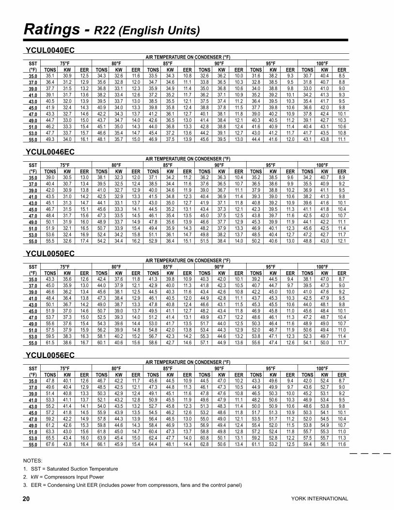
Ratings - R22 (English Units)
NOTES:1. SST = Saturated Suction Temperature2. kW = Compressors Input Power3. EER = Condensing Unit EER (includes power from compressors, fans and the control panel)
YCUL0040EC AIR TEMPERATURE ON CONDENSER (°F)
SST(°F)
75°F 80°F 85°F 90°F 95°F 100°FTONS KW EER TONS KW EER TONS KW EER TONS KW EER TONS KW EER TONS KW EER
35.0 35.1 30.9 12.5 34.3 32.6 11.6 33.5 34.3 10.8 32.6 36.2 10.0 31.6 38.2 9.3 30.7 40.4 8.537.0 36.4 31.2 12.9 35.6 32.8 12.0 34.7 34.6 11.1 33.8 36.5 10.3 32.8 38.5 9.5 31.8 40.7 8.839.0 37.7 31.5 13.2 36.8 33.1 12.3 35.9 34.9 11.4 35.0 36.8 10.6 34.0 38.8 9.8 33.0 41.0 9.041.0 39.1 31.7 13.6 38.2 33.4 12.6 37.2 35.2 11.7 36.2 37.1 10.9 35.2 39.2 10.1 34.2 41.3 9.343.0 40.5 32.0 13.9 39.5 33.7 13.0 38.5 35.5 12.1 37.5 37.4 11.2 36.4 39.5 10.3 35.4 41.7 9.545.0 41.9 32.4 14.3 40.9 34.0 13.3 39.8 35.8 12.4 38.8 37.8 11.5 37.7 39.8 10.6 36.6 42.0 9.847.0 43.3 32.7 14.6 42.2 34.3 13.7 41.2 36.1 12.7 40.1 38.1 11.8 39.0 40.2 10.9 37.8 42.4 10.149.0 44.7 33.0 15.0 43.7 34.7 14.0 42.6 36.5 13.0 41.4 38.4 12.1 40.3 40.5 11.2 39.1 42.7 10.351.0 46.2 33.3 15.4 45.1 35.0 14.3 44.0 36.8 13.3 42.8 38.8 12.4 41.6 40.9 11.4 40.4 43.1 10.653.0 47.7 33.7 15.7 46.6 35.4 14.7 45.4 37.2 13.6 44.2 39.1 12.7 43.0 41.2 11.7 41.7 43.5 10.855.0 49.3 34.0 16.1 48.1 35.7 15.0 46.9 37.5 13.9 45.6 39.5 13.0 44.4 41.6 12.0 43.1 43.8 11.1
YCUL0046EC AIR TEMPERATURE ON CONDENSER (°F)
SST(°F)
75°F 80°F 85°F 90°F 95°F 100°FTONS KW EER TONS KW EER TONS KW EER TONS KW EER TONS KW EER TONS KW EER
35.0 39.0 30.5 13.0 38.1 32.3 12.0 37.1 34.2 11.2 36.2 36.3 10.4 35.2 38.5 9.6 34.2 40.7 8.937.0 40.4 30.7 13.4 39.5 32.5 12.4 38.5 34.4 11.6 37.6 36.5 10.7 36.5 38.6 9.9 35.5 40.9 9.239.0 42.0 30.9 13.8 41.0 32.7 12.9 40.0 34.6 11.9 39.0 36.7 11.1 37.9 38.8 10.2 36.9 41.1 9.541.0 43.5 31.0 14.2 42.5 32.9 13.3 41.5 34.8 12.3 40.4 36.9 11.4 39.3 39.0 10.6 38.2 41.3 9.843.0 45.1 31.3 14.7 44.1 33.1 13.7 43.0 35.0 12.7 41.9 37.1 11.8 40.8 39.2 10.9 39.6 41.6 10.145.0 46.7 31.5 15.1 45.6 33.3 14.1 44.5 35.2 13.1 43.4 37.3 12.1 42.3 39.5 11.3 41.1 41.8 10.447.0 48.4 31.7 15.6 47.3 33.5 14.5 46.1 35.4 13.5 45.0 37.5 12.5 43.8 39.7 11.6 42.5 42.0 10.749.0 50.1 31.9 16.0 48.9 33.7 14.9 47.8 35.6 13.9 46.6 37.7 12.9 45.3 39.9 11.9 44.1 42.2 11.151.0 51.9 32.1 16.5 50.7 33.9 15.4 49.4 35.9 14.3 48.2 37.9 13.3 46.9 40.1 12.3 45.6 42.5 11.453.0 53.6 32.4 16.9 52.4 34.2 15.8 51.1 36.1 14.7 49.8 38.2 13.7 48.5 40.4 12.7 47.2 42.7 11.755.0 55.5 32.6 17.4 54.2 34.4 16.2 52.9 36.4 15.1 51.5 38.4 14.0 50.2 40.6 13.0 48.8 43.0 12.1
YCUL0050EC AIR TEMPERATURE ON CONDENSER (°F)
SST(°F)
75°F 80°F 85°F 90°F 95°F 100°FTONS KW EER TONS KW EER TONS KW EER TONS KW EER TONS KW EER TONS KW EER
35.0 43.3 35.6 12.6 42.4 37.6 11.8 41.3 39.8 10.9 40.3 42.0 10.1 39.2 44.5 9.4 38.1 47.0 8.737.0 45.0 35.9 13.0 44.0 37.9 12.1 42.9 40.0 11.3 41.8 42.3 10.5 40.7 44.7 9.7 39.5 47.3 9.039.0 46.6 36.2 13.4 45.6 38.1 12.5 44.5 40.3 11.6 43.4 42.6 10.8 42.2 45.0 10.0 41.0 47.6 9.241.0 48.4 36.4 13.8 47.3 38.4 12.9 46.1 40.5 12.0 44.9 42.8 11.1 43.7 45.3 10.3 42.5 47.9 9.543.0 50.1 36.7 14.2 49.0 38.7 13.3 47.8 40.8 12.4 46.6 43.1 11.5 45.3 45.5 10.6 44.0 48.1 9.845.0 51.9 37.0 14.6 50.7 39.0 13.7 49.5 41.1 12.7 48.2 43.4 11.8 46.9 45.8 11.0 45.6 48.4 10.147.0 53.7 37.3 15.0 52.5 39.3 14.0 51.2 41.4 13.1 49.9 43.7 12.2 48.6 46.1 11.3 47.2 48.7 10.449.0 55.6 37.6 15.4 54.3 39.6 14.4 53.0 41.7 13.5 51.7 44.0 12.5 50.3 46.4 11.6 48.9 49.0 10.751.0 57.5 37.9 15.9 56.2 39.9 14.8 54.8 42.0 13.8 53.4 44.3 12.9 52.0 46.7 11.9 50.6 49.4 11.053.0 59.5 38.3 16.3 58.1 40.2 15.2 56.7 42.3 14.2 55.3 44.6 13.2 53.8 47.1 12.3 52.3 49.7 11.455.0 61.5 38.6 16.7 60.1 40.6 15.6 58.6 42.7 14.6 57.1 44.9 13.6 55.6 47.4 12.6 54.1 50.0 11.7
YCUL0056EC AIR TEMPERATURE ON CONDENSER (°F)
SST(°F)
75°F 80°F 85°F 90°F 95°F 100°FTONS KW EER TONS KW EER TONS KW EER TONS KW EER TONS KW EER TONS KW EER
35.0 47.8 40.1 12.6 46.7 42.2 11.7 45.6 44.5 10.9 44.5 47.0 10.2 43.3 49.6 9.4 42.0 52.4 8.737.0 49.6 40.4 12.9 48.5 42.5 12.1 47.3 44.8 11.3 46.1 47.3 10.5 44.9 49.9 9.7 43.6 52.7 9.039.0 51.4 40.8 13.3 50.3 42.9 12.4 49.1 45.1 11.6 47.8 47.6 10.8 46.5 50.3 10.0 45.2 53.1 9.241.0 53.3 41.1 13.7 52.1 43.2 12.8 50.9 45.5 11.9 49.6 47.9 11.1 48.2 50.6 10.3 46.9 53.4 9.543.0 55.2 41.4 14.1 54.0 43.5 13.2 52.7 45.8 12.3 51.3 48.3 11.4 50.0 50.9 10.6 48.6 53.8 9.845.0 57.2 41.8 14.5 55.9 43.9 13.5 54.5 46.2 12.6 53.2 48.6 11.8 51.7 51.3 10.9 50.3 54.1 10.147.0 59.2 42.2 14.9 57.8 44.3 13.9 56.4 46.5 13.0 55.0 49.0 12.1 53.5 51.7 11.2 52.0 54.5 10.449.0 61.2 42.6 15.3 59.8 44.6 14.3 58.4 46.9 13.3 56.9 49.4 12.4 55.4 52.0 11.5 53.8 54.9 10.751.0 63.3 43.0 15.6 61.8 45.0 14.7 60.4 47.3 13.7 58.8 49.8 12.8 57.2 52.4 11.8 55.7 55.3 11.053.0 65.5 43.4 16.0 63.9 45.4 15.0 62.4 47.7 14.0 60.8 50.1 13.1 59.2 52.8 12.2 57.5 55.7 11.355.0 67.6 43.8 16.4 66.1 45.9 15.4 64.4 48.1 14.4 62.8 50.6 13.4 61.1 53.2 12.5 59.4 56.1 11.6
YORK INTERNATIONAL20 YORK INTERNATIONAL 21
FORM 150.63-EG1
NOTES:1. SST = Saturated Suction Temperature2. kW = Compressors Input Power3. EER = Condensing Unit EER (includes power from compressors, fans and the control panel)
YCUL0040EC AIR TEMPERATURE ON CONDENSER (°F)
SST(°F)
105°F 110°F 115°F 120°F 125°FTONS KW EER TONS KW EER TONS KW EER TONS KW EER TONS KW EER
35.0 29.7 42.6 7.8 28.6 45.0 7.2 27.5 47.5 6.6 26.4 50.1 6.0 17.6 32.3 6.037.0 30.8 43.0 8.1 29.7 45.4 7.4 28.6 47.9 6.8 27.4 50.5 6.2 18.4 32.5 6.239.0 31.9 43.3 8.3 30.8 45.7 7.6 29.7 48.3 7.0 28.5 50.9 6.4 19.1 32.7 6.541.0 33.1 43.7 8.5 31.9 46.1 7.8 30.8 48.7 7.2 20.6 31.1 7.3 19.8 32.9 6.743.0 34.2 44.0 8.8 33.1 46.5 8.1 31.9 49.0 7.4 21.4 31.3 7.5 20.6 33.1 6.945.0 35.4 44.3 9.0 34.3 46.8 8.3 33.0 49.4 7.6 22.2 31.5 7.8 21.4 33.2 7.147.0 36.7 44.7 9.3 35.5 47.2 8.5 34.2 49.8 7.8 23.0 31.6 8.0 22.2 33.4 7.449.0 37.9 45.1 9.5 36.7 47.6 8.7 35.4 50.2 8.0 23.9 31.8 8.3 23.0 33.6 7.651.0 39.2 45.4 9.7 37.9 47.9 9.0 36.6 50.6 8.2 24.7 31.9 8.5 23.8 33.7 7.853.0 40.5 45.8 10.0 39.2 48.3 9.2 37.8 51.0 8.4 25.6 32.1 8.8 24.7 33.9 8.155.0 41.8 46.2 10.2 40.4 48.7 9.4 27.4 30.6 9.8 26.5 32.3 9.1 25.5 34.1 8.3
YCUL0046EC AIR TEMPERATURE ON CONDENSER (°F)
SST(°F)
105°F 110°F 115°F 120°F 125°FTONS KW EER TONS KW EER TONS KW EER TONS KW EER TONS KW EER
35.0 33.2 43.1 8.2 32.2 45.6 7.5 31.1 48.2 6.9 30.0 51.0 6.4 29.0 53.9 5.837.0 34.5 43.3 8.5 33.4 45.8 7.8 32.3 48.5 7.2 31.2 51.2 6.6 15.5 24.5 6.239.0 35.8 43.5 8.7 34.7 46.1 8.0 33.6 48.7 7.4 32.4 51.5 6.8 16.1 24.6 6.441.0 37.1 43.8 9.0 36.0 46.3 8.3 34.8 49.0 7.7 33.7 51.7 7.0 16.7 24.6 6.643.0 38.5 44.0 9.3 37.3 46.6 8.6 36.1 49.2 7.9 34.9 52.0 7.3 17.4 24.7 6.945.0 39.9 44.2 9.6 38.6 46.8 8.8 37.4 49.5 8.2 36.2 52.3 7.5 18.0 24.8 7.147.0 41.3 44.5 9.9 40.1 47.0 9.1 38.8 49.7 8.4 37.5 52.6 7.7 18.7 24.8 7.449.0 42.8 44.7 10.2 41.5 47.3 9.4 40.2 50.0 8.7 38.9 52.8 8.0 19.4 24.9 7.651.0 44.3 44.9 10.5 43.0 47.5 9.7 41.6 50.3 8.9 40.2 53.1 8.2 20.1 25.0 7.953.0 45.8 45.2 10.8 44.5 47.8 10.0 43.1 50.5 9.2 41.7 53.4 8.5 20.9 25.0 8.255.0 47.4 45.4 11.1 46.0 48.1 10.3 44.5 50.8 9.5 43.1 53.7 8.7 21.6 25.1 8.4
YCUL0050EC AIR TEMPERATURE ON CONDENSER (°F)
SST(°F)
105°F 110°F 115°F 120°F 125°FTONS KW EER TONS KW EER TONS KW EER TONS KW EER TONS KW EER
35.0 36.9 49.7 8.0 35.7 52.6 7.4 34.5 55.6 6.8 33.2 58.7 6.2 16.6 27.8 6.037.0 38.3 50.0 8.3 37.1 52.9 7.6 35.8 55.9 7.0 34.5 59.1 6.4 17.3 27.9 6.239.0 39.8 50.3 8.5 38.5 53.2 7.9 37.2 56.2 7.2 35.8 59.4 6.6 18.0 28.0 6.441.0 41.2 50.6 8.8 39.9 53.5 8.1 38.6 56.6 7.4 37.2 59.7 6.8 18.7 28.1 6.643.0 42.7 50.9 9.1 41.4 53.8 8.4 40.0 56.9 7.7 38.6 60.1 7.1 19.4 28.2 6.945.0 44.3 51.2 9.4 42.9 54.1 8.6 41.5 57.2 7.9 29.7 41.4 7.6 20.1 28.3 7.147.0 45.8 51.5 9.6 44.4 54.4 8.9 43.0 57.6 8.2 30.8 41.6 7.8 20.9 28.4 7.449.0 47.5 51.8 9.9 46.0 54.8 9.1 44.5 57.9 8.4 31.9 41.7 8.1 21.7 28.5 7.651.0 49.1 52.1 10.2 47.6 55.1 9.4 46.1 58.2 8.7 33.0 41.9 8.3 22.5 28.5 7.953.0 50.8 52.5 10.5 49.2 55.4 9.7 47.6 58.6 8.9 24.1 27.0 8.8 23.3 28.6 8.255.0 52.5 52.8 10.8 50.9 55.8 9.9 49.3 59.0 9.2 24.9 27.1 9.1 24.1 28.7 8.4
YCUL0056EC AIR TEMPERATURE ON CONDENSER (°F)
SST(°F)
105°F 110°F 115°F 120°F 125°FTONS KW EER TONS KW EER TONS KW EER TONS KW EER TONS KW EER
35.0 40.7 55.4 8.0 39.3 58.5 7.4 37.9 61.8 6.7 36.4 65.3 6.2 18.3 30.7 6.137.0 42.2 55.7 8.3 40.8 58.9 7.6 39.4 62.2 7.0 37.9 65.7 6.4 19.1 30.8 6.339.0 43.8 56.1 8.5 42.4 59.2 7.8 40.9 62.6 7.2 39.3 66.1 6.6 19.9 31.0 6.541.0 45.4 56.4 8.8 44.0 59.6 8.1 42.4 63.0 7.4 40.9 66.6 6.8 20.6 31.1 6.843.0 47.1 56.8 9.1 45.6 60.0 8.3 44.0 63.4 7.7 42.4 67.0 7.0 21.4 31.2 7.045.0 48.8 57.2 9.3 47.2 60.4 8.6 45.6 63.8 7.9 44.0 67.4 7.2 22.3 31.3 7.247.0 50.5 57.6 9.6 48.9 60.8 8.8 47.2 64.2 8.1 45.6 67.9 7.4 23.1 31.4 7.549.0 52.2 57.9 9.9 50.6 61.2 9.1 48.9 64.6 8.4 24.8 29.7 8.4 23.9 31.5 7.851.0 54.0 58.3 10.1 52.3 61.6 9.3 50.6 65.1 8.6 25.7 29.8 8.7 24.8 31.6 8.053.0 55.8 58.7 10.4 54.1 62.0 9.6 52.3 65.5 8.8 26.6 29.9 9.0 25.7 31.7 8.355.0 57.7 59.2 10.7 55.9 62.4 9.9 54.1 65.9 9.1 27.6 30.0 9.3 26.6 31.8 8.6
YORK INTERNATIONAL22 YORK INTERNATIONAL 23
FORM 150.63-EG1
Ratings - R22 (English Units)
NOTES:1. SST = Saturated Suction Temperature2. kW = Compressors Input Power3. EER = Condensing Unit EER (includes power from compressors, fans and the control panel)
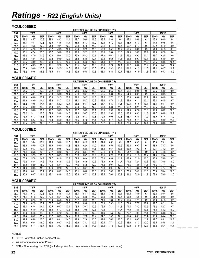
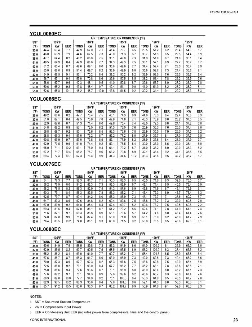
YCUL0060EC AIR TEMPERATURE ON CONDENSER (°F)
SST(°F)
75°F 80°F 85°F 90°F 95°F 100°FTONS KW EER TONS KW EER TONS KW EER TONS KW EER TONS KW EER TONS KW EER
35.0 52.2 45.7 12.2 51.0 48.2 11.4 49.7 50.9 10.6 48.5 53.8 9.8 47.1 56.8 9.1 45.8 60.0 8.437.0 54.1 46.1 12.6 52.9 48.6 11.7 51.6 51.3 10.9 50.3 54.2 10.1 48.9 57.3 9.3 47.5 60.5 8.639.0 56.1 46.5 12.9 54.8 49.1 12.0 53.4 51.8 11.2 52.1 54.7 10.4 50.7 57.7 9.6 49.2 61.0 8.941.0 58.1 47.0 13.3 56.7 49.5 12.4 55.4 52.2 11.5 53.9 55.1 10.7 52.5 58.2 9.9 51.0 61.5 9.143.0 60.1 47.4 13.6 58.7 50.0 12.7 57.3 52.7 11.8 55.8 55.6 11.0 54.3 58.7 10.1 52.8 62.0 9.445.0 62.2 47.9 13.9 60.8 50.4 13.0 59.3 53.2 12.1 57.8 56.1 11.2 56.2 59.2 10.4 54.7 62.5 9.647.0 64.3 48.4 14.3 62.8 50.9 13.3 61.3 53.6 12.4 59.8 56.6 11.5 58.2 59.7 10.7 56.5 63.0 9.949.0 66.5 48.9 14.6 65.0 51.4 13.7 63.4 54.2 12.7 61.8 57.1 11.8 60.1 60.2 11.0 58.5 63.5 10.151.0 68.7 49.5 15.0 67.1 52.0 14.0 65.5 54.7 13.0 63.8 57.6 12.1 62.2 60.8 11.2 60.4 64.1 10.453.0 70.9 50.0 15.3 69.3 52.5 14.3 67.6 55.2 13.3 65.9 58.2 12.4 64.2 61.3 11.5 62.4 64.7 10.755.0 73.2 50.6 15.6 71.5 53.1 14.6 69.8 55.8 13.6 68.1 58.8 12.7 66.3 61.9 11.8 64.4 65.3 10.9
YCUL0066EC AIR TEMPERATURE ON CONDENSER (°F)
SST(°F)
75°F 80°F 85°F 90°F 95°F 100°FTONS KW EER TONS KW EER TONS KW EER TONS KW EER TONS KW EER TONS KW EER
35.0 57.6 47.7 13.0 56.2 50.4 12.1 54.9 53.3 11.2 53.5 56.3 10.4 52.1 59.6 9.6 50.6 63.0 8.937.0 59.7 48.1 13.3 58.3 50.8 12.4 56.9 53.7 11.5 55.5 56.8 10.7 54.0 60.1 9.9 52.5 63.5 9.139.0 61.8 48.6 13.7 60.4 51.3 12.7 59.0 54.2 11.8 57.5 57.3 11.0 56.0 60.6 10.2 54.4 64.0 9.441.0 64.0 49.0 14.1 62.6 51.7 13.1 61.1 54.7 12.2 59.6 57.8 11.3 58.0 61.1 10.4 56.4 64.5 9.743.0 66.2 49.5 14.4 64.7 52.2 13.4 63.2 55.1 12.5 61.7 58.3 11.6 60.1 61.6 10.7 58.4 65.1 9.945.0 68.5 50.0 14.8 67.0 52.7 13.8 65.4 55.7 12.8 63.8 58.8 11.9 62.2 62.1 11.0 60.5 65.6 10.247.0 70.8 50.6 15.1 69.2 53.3 14.1 67.7 56.2 13.1 66.0 59.3 12.2 64.3 62.6 11.3 62.6 66.2 10.549.0 73.2 51.1 15.5 71.6 53.8 14.5 69.9 56.7 13.5 68.2 59.9 12.5 66.5 63.2 11.6 64.7 66.8 10.751.0 75.6 51.7 15.8 73.9 54.4 14.8 72.2 57.3 13.8 70.5 60.5 12.8 68.7 63.8 11.9 66.9 67.4 11.053.0 78.0 52.3 16.2 76.3 55.0 15.1 74.6 57.9 14.1 72.8 61.1 13.1 71.0 64.4 12.2 69.1 68.0 11.355.0 80.5 52.9 16.5 78.7 55.6 15.4 77.0 58.6 14.4 75.2 61.7 13.4 73.3 65.1 12.4 71.3 68.6 11.5
YCUL0076EC AIR TEMPERATURE ON CONDENSER (°F)
SST(°F)
75°F 80°F 85°F 90°F 95°F 100°FTONS KW EER TONS KW EER TONS KW EER TONS KW EER TONS KW EER TONS KW EER
35.0 64.2 55.4 12.4 62.6 58.6 11.5 61.0 61.9 10.7 59.4 65.5 9.9 57.7 69.2 9.1 55.9 73.1 8.437.0 66.6 55.9 12.7 64.9 59.0 11.8 63.3 62.4 11.0 61.6 65.9 10.2 59.8 69.7 9.4 58.0 73.7 8.639.0 69.0 56.3 13.1 67.3 59.5 12.2 65.6 62.8 11.3 63.8 66.4 10.5 62.0 70.2 9.7 60.1 74.2 8.941.0 71.4 56.8 13.5 69.7 60.0 12.5 67.9 63.4 11.6 66.1 67.0 10.8 64.2 70.8 9.9 62.3 74.8 9.243.0 74.0 57.3 13.8 72.2 60.5 12.9 70.3 63.9 11.9 68.5 67.5 11.1 66.5 71.3 10.2 64.5 75.4 9.445.0 76.6 57.8 14.2 74.7 61.0 13.2 72.8 64.4 12.3 70.8 68.0 11.4 68.9 71.9 10.5 66.8 75.9 9.747.0 79.2 58.4 14.6 77.3 61.5 13.6 75.3 64.9 12.6 73.3 68.6 11.7 71.2 72.4 10.8 69.1 76.5 10.049.0 81.9 58.9 15.0 79.9 62.1 13.9 77.9 65.5 12.9 75.8 69.1 12.0 73.6 73.0 11.1 71.5 77.1 10.251.0 84.6 59.5 15.3 82.6 62.6 14.3 80.5 66.1 13.3 78.3 69.7 12.3 76.1 73.6 11.4 73.9 77.7 10.553.0 87.4 60.1 15.7 85.3 63.2 14.6 83.1 66.6 13.6 80.9 70.3 12.6 78.6 74.2 11.6 76.3 78.4 10.855.0 90.3 60.7 16.1 88.1 63.8 15.0 85.8 67.3 13.9 83.5 70.9 12.9 81.2 74.9 11.9 78.8 79.0 11.0
YCUL0080EC AIR TEMPERATURE ON CONDENSER (°F)
SST(°F)
75°F 80°F 85°F 90°F 95°F 100°FTONS KW EER TONS KW EER TONS KW EER TONS KW EER TONS KW EER TONS KW EER
35.0 71.4 61.3 12.6 69.8 64.6 11.7 68.1 68.1 10.9 66.4 71.9 10.1 64.5 76.0 9.3 62.6 80.4 8.637.0 74.1 61.8 13.0 72.4 65.1 12.1 70.6 68.6 11.2 68.8 72.5 10.4 66.9 76.6 9.6 64.9 80.9 8.939.0 76.8 62.3 13.3 75.0 65.6 12.4 73.2 69.2 11.6 71.3 73.0 10.7 69.4 77.1 9.9 67.3 81.5 9.241.0 79.6 62.9 13.7 77.7 66.2 12.8 75.8 69.8 11.9 73.9 73.5 11.0 71.9 77.7 10.2 69.7 82.1 9.443.0 82.4 63.4 14.1 80.5 66.7 13.1 78.5 70.3 12.2 76.5 74.1 11.3 74.4 78.2 10.5 72.2 82.7 9.745.0 85.3 64.0 14.5 83.3 67.3 13.5 81.3 70.9 12.6 79.2 74.7 11.7 77.0 78.8 10.8 74.8 83.2 10.047.0 88.3 64.6 14.8 86.2 67.9 13.9 84.1 71.4 12.9 81.9 75.3 12.0 79.7 79.4 11.1 77.4 83.8 10.249.0 91.4 65.2 15.2 89.2 68.5 14.2 87.0 72.0 13.2 84.7 75.9 12.3 82.4 80.1 11.4 80.0 84.4 10.551.0 94.5 65.8 15.6 92.2 69.1 14.6 89.9 72.6 13.6 87.6 76.5 12.6 85.1 80.7 11.7 82.7 85.1 10.853.0 97.6 66.4 16.0 95.3 69.7 14.9 92.9 73.3 13.9 90.5 77.1 12.9 88.0 81.3 12.0 85.5 85.8 11.155.0 100.9 67.1 16.4 98.4 70.3 15.3 96.0 73.9 14.3 93.4 77.8 13.3 90.9 81.9 12.3 88.3 86.4 11.4
YORK INTERNATIONAL22 YORK INTERNATIONAL 23
FORM 150.63-EG1
NOTES:1. SST = Saturated Suction Temperature2. kW = Compressors Input Power3. EER = Condensing Unit EER (includes power from compressors, fans and the control panel)
YCUL0060EC AIR TEMPERATURE ON CONDENSER (°F)
SST(°F)
105°F 110°F 115°F 120°F 125°FTONS KW EER TONS KW EER TONS KW EER TONS KW EER TONS KW EER
35.0 44.4 63.4 7.7 42.9 67.0 7.1 41.4 70.7 6.5 29.5 51.2 6.2 28.4 54.0 5.737.0 46.0 63.9 7.9 44.6 67.5 7.3 43.0 71.3 6.7 30.7 51.5 6.5 29.5 54.4 5.939.0 47.7 64.4 8.2 46.2 68.0 7.5 33.1 49.0 7.3 31.9 51.8 6.7 21.8 35.1 6.441.0 49.5 64.9 8.4 47.9 68.6 7.7 34.3 49.3 7.5 33.1 52.1 6.9 22.7 35.2 6.743.0 51.2 65.4 8.7 49.6 69.1 8.0 35.6 49.6 7.7 34.4 52.4 7.1 23.5 35.4 6.945.0 53.0 66.0 8.9 51.4 69.7 8.2 36.9 49.9 8.0 35.6 52.7 7.3 24.4 35.6 7.147.0 54.9 66.5 9.1 53.1 70.2 8.4 38.2 50.2 8.2 36.9 53.0 7.6 25.3 35.7 7.449.0 56.7 67.1 9.4 55.0 70.8 8.6 39.6 50.5 8.5 38.2 53.4 7.8 26.2 35.9 7.651.0 58.6 67.7 9.6 42.3 48.1 9.5 41.0 50.8 8.7 39.6 53.7 8.0 27.2 36.0 7.853.0 60.6 68.2 9.8 43.8 48.4 9.7 42.4 51.1 9.0 41.0 54.0 8.2 28.2 36.2 8.155.0 62.6 68.8 10.1 45.2 48.7 10.0 43.8 51.5 9.2 30.2 34.4 9.1 29.2 36.3 8.3
YCUL0066EC AIR TEMPERATURE ON CONDENSER (°F)
SST(°F)
105°F 110°F 115°F 120°F 125°FTONS KW EER TONS KW EER TONS KW EER TONS KW EER TONS KW EER
35.0 49.2 66.6 8.2 47.7 70.4 7.5 46.1 74.3 6.9 44.6 78.3 6.4 22.4 36.8 6.337.0 51.0 67.1 8.4 49.5 70.9 7.8 47.9 74.8 7.1 46.3 78.9 6.6 23.2 37.0 6.539.0 52.9 67.6 8.7 51.3 71.4 8.0 49.6 75.4 7.4 48.0 79.5 6.8 24.1 37.2 6.841.0 54.8 68.2 8.9 53.1 72.0 8.2 51.5 76.0 7.6 25.9 35.3 7.6 25.0 37.4 7.043.0 56.8 68.7 9.2 55.1 72.6 8.5 53.3 76.6 7.8 26.9 35.5 7.9 26.0 37.5 7.245.0 58.8 69.3 9.4 57.0 73.2 8.7 55.2 77.2 8.0 27.9 35.7 8.1 27.0 37.7 7.547.0 60.8 69.9 9.7 59.0 73.8 8.9 57.1 77.9 8.2 28.9 35.8 8.4 28.0 37.9 7.749.0 62.9 70.5 9.9 61.0 74.4 9.2 59.1 78.5 8.4 30.0 36.0 8.6 29.0 38.1 8.051.0 65.0 71.1 10.2 63.1 75.0 9.4 61.1 79.2 8.7 31.0 36.2 8.9 30.0 38.3 8.253.0 67.2 71.7 10.4 65.2 75.7 9.6 63.2 79.8 8.9 32.1 36.4 9.2 31.1 38.5 8.555.0 69.4 72.4 10.7 67.3 76.4 9.9 34.3 34.6 10.2 33.3 36.6 9.5 32.2 38.7 8.7
YCUL0076EC AIR TEMPERATURE ON CONDENSER (°F)
SST(°F)
105°F 110°F 115°F 120°F 125°FTONS KW EER TONS KW EER TONS KW EER TONS KW EER TONS KW EER
35.0 54.1 77.3 7.7 52.3 81.7 7.1 50.3 86.3 6.5 40.5 71.0 6.3 39.0 75.0 5.737.0 56.2 77.9 8.0 54.2 82.3 7.3 52.3 86.9 6.7 42.1 71.4 6.5 40.5 75.4 5.939.0 58.2 78.5 8.2 56.3 82.9 7.5 54.3 87.6 6.9 43.8 71.9 6.7 42.1 75.9 6.141.0 60.3 79.1 8.4 58.3 83.5 7.8 56.3 88.2 7.1 45.4 72.3 6.9 43.7 76.4 6.343.0 62.5 79.7 8.7 60.4 84.2 8.0 58.3 88.9 7.3 47.1 72.7 7.1 37.6 60.2 6.745.0 64.7 80.3 8.9 62.6 84.8 8.2 60.4 89.6 7.5 48.8 73.2 7.3 39.0 60.5 7.047.0 67.0 80.9 9.2 64.8 85.4 8.4 52.4 69.7 8.2 50.6 73.7 7.5 40.5 60.8 7.249.0 69.3 81.5 9.4 67.0 86.1 8.7 54.2 70.2 8.5 52.4 74.1 7.8 41.9 61.1 7.451.0 71.6 82.1 9.7 69.3 86.8 8.9 56.1 70.6 8.7 54.2 74.6 8.0 43.4 61.4 7.653.0 74.0 82.8 9.9 71.6 87.4 9.1 58.0 71.0 8.9 56.1 75.0 8.2 45.0 61.7 7.955.0 76.4 83.5 10.2 74.0 88.1 9.3 60.0 71.5 9.2 58.0 75.5 8.5 46.6 62.0 8.1
YCUL0080EC AIR TEMPERATURE ON CONDENSER (°F)
SST(°F)
105°F 110°F 115°F 120°F 125°FTONS KW EER TONS KW EER TONS KW EER TONS KW EER TONS KW EER
35.0 60.6 84.9 7.9 58.5 89.8 7.3 56.3 94.9 6.6 54.0 100.2 6.1 35.9 65.2 6.037.0 62.9 85.5 8.2 60.7 90.5 7.5 58.5 95.5 6.9 56.2 100.9 6.3 37.4 65.5 6.239.0 65.2 86.2 8.4 63.0 91.0 7.7 60.7 96.2 7.1 58.4 101.6 6.5 38.9 65.8 6.441.0 67.6 86.7 8.7 65.3 91.7 8.0 63.0 96.9 7.3 42.0 62.6 7.3 40.4 66.2 6.643.0 70.0 87.3 8.9 67.7 92.3 8.2 65.3 97.6 7.5 43.6 62.8 7.5 42.0 66.4 6.945.0 72.5 88.0 9.2 70.1 93.0 8.4 67.7 98.2 7.7 45.2 63.1 7.8 43.6 66.8 7.147.0 75.0 88.6 9.4 72.6 93.6 8.7 70.1 98.9 8.0 46.9 63.4 8.0 45.2 67.1 7.349.0 77.6 89.2 9.7 75.1 94.3 8.9 72.6 99.6 8.2 48.6 63.7 8.3 46.8 67.4 7.651.0 80.3 89.8 10.0 77.7 94.9 9.2 75.1 100.3 8.4 50.3 64.0 8.5 48.5 67.7 7.853.0 82.9 90.5 10.2 80.3 95.6 9.4 77.6 101.0 8.6 52.1 64.3 8.8 50.3 68.0 8.155.0 85.7 91.2 10.5 83.0 96.3 9.7 80.2 101.7 8.9 53.9 64.6 9.1 52.0 68.3 8.3
YORK INTERNATIONAL24 YORK INTERNATIONAL 25
FORM 150.63-EG1
Ratings - R22 (English Units)
NOTES:1. SST = Saturated Suction Temperature2. kW = Compressors Input Power3. EER = Condensing Unit EER (includes power from compressors, fans and the control panel)
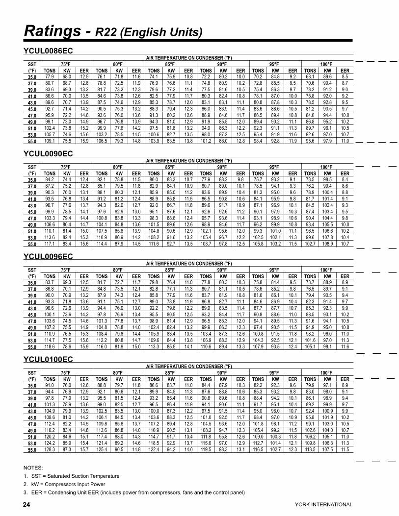
YCUL0086EC AIR TEMPERATURE ON CONDENSER (°F)
SST(°F)
75°F 80°F 85°F 90°F 95°F 100°FTONS KW EER TONS KW EER TONS KW EER TONS KW EER TONS KW EER TONS KW EER
35.0 77.9 68.0 12.5 76.1 71.8 11.6 74.1 75.9 10.8 72.2 80.2 10.0 70.2 84.8 9.2 68.1 89.6 8.537.0 80.7 68.7 12.8 78.8 72.5 11.9 76.9 76.6 11.1 74.8 80.9 10.2 72.8 85.5 9.5 70.6 90.4 8.739.0 83.6 69.3 13.2 81.7 73.2 12.3 79.6 77.2 11.4 77.5 81.6 10.5 75.4 86.3 9.7 73.2 91.2 9.041.0 86.6 70.0 13.5 84.6 73.8 12.6 82.5 77.9 11.7 80.3 82.4 10.8 78.1 87.0 10.0 75.8 92.0 9.243.0 89.6 70.7 13.9 87.5 74.6 12.9 85.3 78.7 12.0 83.1 83.1 11.1 80.8 87.8 10.3 78.5 92.8 9.545.0 92.7 71.4 14.2 90.5 75.3 13.2 88.3 79.4 12.3 86.0 83.9 11.4 83.6 88.6 10.5 81.2 93.5 9.747.0 95.9 72.2 14.6 93.6 76.0 13.6 91.3 80.2 12.6 88.9 84.6 11.7 86.5 89.4 10.8 84.0 94.4 10.049.0 99.1 73.0 14.9 96.7 76.8 13.9 94.3 81.0 12.9 91.9 85.5 12.0 89.4 90.2 11.1 86.8 95.2 10.251.0 102.4 73.8 15.2 99.9 77.6 14.2 97.5 81.8 13.2 94.9 86.3 12.2 92.3 91.1 11.3 89.7 96.1 10.553.0 105.7 74.6 15.6 103.2 78.5 14.5 100.6 82.7 13.5 98.0 87.2 12.5 95.4 91.9 11.6 92.6 97.0 10.755.0 109.1 75.5 15.9 106.5 79.3 14.8 103.9 83.5 13.8 101.2 88.0 12.8 98.4 92.8 11.9 95.6 97.9 11.0
YCUL0090EC AIR TEMPERATURE ON CONDENSER (°F)
SST(°F)
75°F 80°F 85°F 90°F 95°F 100°FTONS KW EER TONS KW EER TONS KW EER TONS KW EER TONS KW EER TONS KW EER
35.0 84.2 74.4 12.4 82.1 78.8 11.5 80.0 83.3 10.7 77.9 88.2 9.8 75.7 93.2 9.1 73.5 98.5 8.437.0 87.2 75.2 12.8 85.1 79.5 11.8 82.9 84.1 10.9 80.7 89.0 10.1 78.5 94.1 9.3 76.2 99.4 8.639.0 90.3 76.0 13.1 88.1 80.3 12.1 85.9 85.0 11.2 83.6 89.9 10.4 81.3 95.0 9.6 78.9 100.4 8.841.0 93.5 76.8 13.4 91.2 81.2 12.4 88.9 85.8 11.5 86.5 90.8 10.6 84.1 95.9 9.8 81.7 101.4 9.143.0 96.7 77.6 13.7 94.3 82.0 12.7 92.0 86.7 11.8 89.6 91.7 10.9 87.1 96.9 10.1 84.5 102.4 9.345.0 99.9 78.5 14.1 97.6 82.9 13.0 95.1 87.6 12.1 92.6 92.6 11.2 90.1 97.9 10.3 87.4 103.4 9.547.0 103.3 79.4 14.4 100.8 83.8 13.3 98.3 88.6 12.4 95.7 93.6 11.4 93.1 98.9 10.6 90.4 104.4 9.849.0 106.6 80.4 14.7 104.1 84.8 13.6 101.5 89.6 12.6 98.9 94.6 11.7 96.2 99.9 10.8 93.4 105.5 10.051.0 110.1 81.4 15.0 107.5 85.8 13.9 104.8 90.6 12.9 102.1 95.6 12.0 99.3 101.0 11.1 96.5 106.6 10.253.0 113.6 82.4 15.3 110.9 86.9 14.2 108.2 91.6 13.2 105.4 96.7 12.2 102.5 102.1 11.3 99.6 107.8 10.455.0 117.1 83.4 15.6 114.4 87.9 14.5 111.6 92.7 13.5 108.7 97.8 12.5 105.8 103.2 11.5 102.7 108.9 10.7
YCUL0096EC AIR TEMPERATURE ON CONDENSER (°F)
SST(°F)
75°F 80°F 85°F 90°F 95°F 100°FTONS KW EER TONS KW EER TONS KW EER TONS KW EER TONS KW EER TONS KW EER
35.0 83.7 69.3 12.5 81.7 72.7 11.7 79.8 76.4 11.0 77.8 80.3 10.3 75.8 84.4 9.5 73.7 88.9 8.937.0 86.8 70.1 12.9 84.8 73.5 12.1 82.8 77.1 11.3 80.7 81.1 10.5 78.6 85.2 9.8 76.5 89.7 9.139.0 90.0 70.9 13.2 87.9 74.3 12.4 85.8 77.9 11.6 83.7 81.9 10.8 81.6 86.1 10.1 79.4 90.5 9.441.0 93.3 71.8 13.6 91.1 75.1 12.7 89.0 78.8 11.9 86.8 82.7 11.1 84.6 86.9 10.4 82.3 91.4 9.743.0 96.6 72.6 13.9 94.4 76.0 13.0 92.2 79.6 12.2 89.9 83.5 11.4 87.7 87.7 10.7 85.3 92.3 9.945.0 100.1 73.6 14.2 97.8 76.9 13.4 95.5 80.5 12.5 93.2 84.4 11.7 90.8 88.6 11.0 88.5 93.1 10.247.0 103.6 74.5 14.6 101.3 77.8 13.7 98.9 81.4 12.9 96.5 85.3 12.0 94.1 89.5 11.3 91.6 94.1 10.549.0 107.2 75.5 14.9 104.8 78.8 14.0 102.4 82.4 13.2 99.9 86.3 12.3 97.4 90.5 11.5 94.9 95.0 10.851.0 110.9 76.5 15.3 108.4 79.8 14.4 105.9 83.4 13.5 103.4 87.3 12.6 100.8 91.5 11.8 98.2 96.0 11.053.0 114.7 77.5 15.6 112.2 80.8 14.7 109.6 84.4 13.8 106.9 88.3 12.9 104.3 92.5 12.1 101.6 97.0 11.355.0 118.6 78.6 15.9 116.0 81.9 15.0 113.3 85.5 14.1 110.6 89.4 13.3 107.9 93.5 12.4 105.1 98.1 11.6
YCUL0100EC AIR TEMPERATURE ON CONDENSER (°F)
SST(°F)
75°F 80°F 85°F 90°F 95°F 100°FTONS KW EER TONS KW EER TONS KW EER TONS KW EER TONS KW EER TONS KW EER
35.0 91.0 76.0 12.6 88.8 79.7 11.8 86.6 83.7 11.0 84.4 87.9 10.3 82.2 92.3 9.6 79.9 97.1 8.937.0 94.4 76.9 12.9 92.1 80.6 12.1 89.9 84.5 11.3 87.6 88.8 10.6 85.3 93.2 9.8 83.0 98.0 9.139.0 97.8 77.9 13.2 95.5 81.5 12.4 93.2 85.4 11.6 90.8 89.6 10.8 88.4 94.2 10.1 86.1 98.9 9.441.0 101.3 78.9 13.6 99.0 82.5 12.7 96.5 86.4 11.9 94.1 90.6 11.1 91.7 95.1 10.4 89.2 99.9 9.743.0 104.9 79.9 13.9 102.5 83.5 13.0 100.0 87.3 12.2 97.5 91.5 11.4 95.0 96.0 10.7 92.4 100.9 9.945.0 108.6 81.0 14.2 106.1 84.5 13.4 103.6 88.3 12.5 101.0 92.5 11.7 98.4 97.0 10.9 95.8 101.9 10.247.0 112.4 82.2 14.5 109.8 85.6 13.7 107.2 89.4 12.8 104.5 93.6 12.0 101.8 98.1 11.2 99.1 103.0 10.549.0 116.2 83.4 14.8 113.6 86.8 14.0 110.9 90.5 13.1 108.2 94.7 12.3 105.4 99.2 11.5 102.6 104.0 10.751.0 120.2 84.6 15.1 117.4 88.0 14.3 114.7 91.7 13.4 111.8 95.8 12.6 109.0 100.3 11.8 106.2 105.1 11.053.0 124.2 85.9 15.4 121.4 89.2 14.6 118.5 92.9 13.7 115.6 97.0 12.9 112.7 101.4 12.1 109.8 106.3 11.355.0 128.3 87.3 15.7 125.4 90.5 14.8 122.4 94.2 14.0 119.5 98.3 13.1 116.5 102.7 12.3 113.5 107.5 11.5

YORK INTERNATIONAL24 YORK INTERNATIONAL 25
FORM 150.63-EG1
NOTES:1. SST = Saturated Suction Temperature2. kW = Compressors Input Power3. EER = Condensing Unit EER (includes power from compressors, fans and the control panel)
YCUL0086EC AIR TEMPERATURE ON CONDENSER (°F)
SST(°F)
105°F 110°F 115°F 120°F 125°FTONS KW EER TONS KW EER TONS KW EER TONS KW EER TONS KW EER
35.0 66.0 94.7 7.8 63.8 100.1 7.2 61.5 105.6 6.6 49.3 86.9 6.3 39.5 71.9 6.037.0 68.4 95.5 8.0 66.2 100.9 7.4 63.9 106.5 6.8 51.2 87.5 6.5 41.1 72.3 6.239.0 70.9 96.3 8.3 68.6 101.7 7.6 55.2 83.5 7.3 53.2 88.2 6.7 42.7 72.7 6.441.0 73.5 97.1 8.5 71.1 102.5 7.8 57.2 84.0 7.6 46.0 69.3 7.2 44.3 73.2 6.643.0 76.1 98.0 8.7 73.6 103.4 8.0 59.3 84.6 7.8 47.7 69.7 7.5 45.9 73.6 6.945.0 78.7 98.8 8.9 76.2 104.3 8.2 61.5 85.2 8.0 49.4 70.1 7.7 47.6 74.1 7.147.0 81.4 99.7 9.2 78.8 105.2 8.4 63.7 85.8 8.2 51.2 70.5 7.9 49.4 74.5 7.349.0 84.2 100.5 9.4 81.5 106.1 8.7 65.9 86.4 8.5 53.0 71.0 8.2 51.2 74.9 7.551.0 87.0 101.4 9.6 70.5 82.4 9.5 68.2 87.0 8.7 54.9 71.4 8.4 53.0 75.4 7.753.0 89.9 102.4 9.9 72.8 83.0 9.7 70.5 87.7 9.0 56.8 71.8 8.7 54.8 75.9 8.055.0 92.8 103.3 10.1 75.3 83.6 10.0 72.8 88.3 9.2 58.7 72.3 8.9 56.7 76.3 8.2
YCUL0090EC AIR TEMPERATURE ON CONDENSER (°F)
SST(°F)
105°F 110°F 115°F 120°F 125°FTONS KW EER TONS KW EER TONS KW EER TONS KW EER TONS KW EER
35.0 71.2 104.1 7.7 69.0 109.8 7.1 66.6 115.8 6.5 44.6 74.2 6.6* 43.0 78.3 6.137.0 73.9 105.0 7.9 71.5 110.9 7.3 69.1 116.9 6.7 46.3 74.7 6.8* 44.7 78.8 6.339.0 76.5 106.0 8.1 74.1 111.9 7.5 71.6 118.0 6.9 48.0 75.2 7.0* 46.3 79.4 6.541.0 79.2 107.0 8.4 76.7 112.9 7.7 74.1 119.1 7.1 49.8 75.7 7.2* 48.1 79.9 6.743.0 82.0 108.1 8.6 79.4 114.0 7.9 53.4 72.2 8.1 51.6 76.2 7.5 49.8 80.5 6.945.0 84.8 109.2 8.8 82.1 115.1 8.1 55.3 72.7 8.4 53.5 76.8 7.7 51.6 81.0 7.147.0 87.7 110.2 9.0 84.9 116.3 8.3 57.3 73.2 8.6 55.4 77.3 7.9 53.5 81.6 7.349.0 90.6 111.4 9.2 87.7 117.5 8.5 59.3 73.7 8.8 57.4 77.9 8.1 55.4 82.2 7.551.0 93.6 112.5 9.4 90.6 118.7 8.7 61.4 74.3 9.1 59.3 78.4 8.4 57.3 82.8 7.753.0 96.6 113.7 9.6 93.5 119.9 8.9 63.4 74.9 9.3 61.4 79.0 8.6 59.3 83.4 7.955.0 99.7 114.9 9.8 67.7 71.4 10.4 65.6 75.4 9.6 63.4 79.6 8.8 61.3 84.0 8.1
YCUL0096EC AIR TEMPERATURE ON CONDENSER (°F)
SST(°F)
105°F 110°F 115°F 120°F 125°FTONS KW EER TONS KW EER TONS KW EER TONS KW EER TONS KW EER
35.0 71.6 93.6 8.2 69.5 98.7 7.6 67.4 104.0 7.0 65.2 109.7 6.5 63.0 115.7 6.037.0 74.4 94.4 8.5 72.2 99.5 7.9 70.0 104.9 7.3 67.8 110.6 6.7 65.5 116.6 6.239.0 77.2 95.3 8.7 74.9 100.4 8.1 72.7 105.8 7.5 70.4 111.6 6.9 68.1 117.6 6.441.0 80.1 96.2 9.0 77.8 101.3 8.3 75.4 106.7 7.7 73.1 112.5 7.1 70.7 118.6 6.643.0 83.0 97.1 9.2 80.7 102.2 8.6 78.3 107.6 7.9 75.9 113.4 7.3 54.2 83.4 6.945.0 86.1 98.0 9.5 83.6 103.1 8.8 81.2 108.6 8.2 78.7 114.4 7.5 56.2 84.0 7.147.0 89.2 98.9 9.8 86.7 104.1 9.1 84.2 109.6 8.4 81.6 115.5 7.8 58.4 84.7 7.349.0 92.4 99.9 10.0 89.8 105.1 9.3 87.2 110.6 8.6 84.6 116.5 8.0 60.5 85.3 7.651.0 95.6 100.9 10.3 93.0 106.1 9.5 90.3 111.7 8.8 87.6 117.6 8.2 62.8 86.0 7.853.0 99.0 101.9 10.5 96.3 107.1 9.8 93.5 112.7 9.1 90.7 118.7 8.4 65.1 86.6 8.055.0 102.4 103.0 10.8 99.6 108.2 10.0 96.8 113.8 9.3 93.9 119.8 8.6 47.3 55.4 8.6
YCUL0100EC AIR TEMPERATURE ON CONDENSER (°F)
SST(°F)
105°F 110°F 115°F 120°F 125°FTONS KW EER TONS KW EER TONS KW EER TONS KW EER TONS KW EER
35.0 77.7 102.2 8.2 75.4 107.6 7.6 73.2 113.2 7.1 70.9 119.2 6.5 68.7 125.4 6.137.0 80.6 103.1 8.5 78.3 108.5 7.9 76.0 114.3 7.3 73.6 120.3 6.7 71.4 126.5 6.239.0 83.7 104.0 8.7 81.2 109.5 8.1 78.9 115.2 7.5 76.5 121.4 6.9 74.1 127.6 6.441.0 86.7 105.0 9.0 84.3 110.5 8.3 81.8 116.3 7.7 79.4 122.4 7.2 76.9 128.8 6.643.0 89.9 106.0 9.2 87.4 111.5 8.6 84.9 117.3 7.9 82.3 123.5 7.4 41.3 57.6 7.245.0 93.2 107.1 9.5 90.6 112.5 8.8 88.0 118.4 8.2 85.3 124.6 7.6 42.9 58.0 7.547.0 96.5 108.1 9.7 93.8 113.7 9.0 91.1 119.5 8.4 88.5 125.8 7.8 44.5 58.4 7.749.0 99.9 109.2 10.0 97.1 114.8 9.3 94.3 120.8 8.6 91.6 127.0 8.0 46.1 58.8 8.051.0 103.3 110.4 10.2 100.5 116.0 9.5 97.7 122.0 8.8 94.8 128.3 8.2 47.8 59.2 8.253.0 106.9 111.5 10.5 104.0 117.2 9.7 101.0 123.2 9.0 98.1 129.6 8.4 49.6 59.6 8.455.0 110.5 112.8 10.7 107.5 118.4 10.0 104.5 124.5 9.3 101.5 130.9 8.6 51.3 60.0 8.7

YORK INTERNATIONAL26 YORK INTERNATIONAL 27
FORM 150.63-EG1
Ratings - R22 (English Units)
NOTES:1. SST = Saturated Suction Temperature2. kW = Compressors Input Power3. EER = Condensing Unit EER (includes power from compressors, fans and the control panel)
YCUL0106EC AIR TEMPERATURE ON CONDENSER (°F)
SST(°F)
75°F 80°F 85°F 90°F 95°F 100°FTONS KW EER TONS KW EER TONS KW EER TONS KW EER TONS KW EER TONS KW EER
35.0 101.1 88.1 12.3 98.7 92.6 11.5 96.2 97.4 10.7 93.7 102.6 9.9 91.1 108.1 9.2 88.5 113.9 8.537.0 104.8 89.2 12.6 102.3 93.7 11.7 99.7 98.5 11.0 97.2 103.7 10.2 94.5 109.2 9.5 91.8 115.1 8.839.0 108.6 90.3 12.9 106.0 94.8 12.0 103.4 99.6 11.2 100.7 104.8 10.5 98.0 110.4 9.7 95.2 116.3 9.041.0 112.5 91.5 13.2 109.8 96.0 12.3 107.1 100.8 11.5 104.4 106.0 10.7 101.5 111.6 10.0 98.7 117.6 9.243.0 116.5 92.7 13.5 113.7 97.2 12.6 110.9 102.0 11.8 108.1 107.2 11.0 105.2 112.8 10.2 102.3 118.9 9.545.0 120.6 94.0 13.8 117.7 98.4 12.9 114.8 103.3 12.1 111.9 108.5 11.3 108.9 114.1 10.5 105.9 120.1 9.747.0 124.8 95.3 14.1 121.8 99.7 13.2 118.8 104.6 12.4 115.8 109.8 11.5 112.8 115.4 10.7 109.7 121.5 9.949.0 129.0 96.6 14.4 126.0 101.1 13.5 122.9 105.9 12.6 119.8 111.1 11.8 116.7 116.8 11.0 113.5 122.9 10.251.0 133.4 98.0 14.7 130.3 102.4 13.8 127.2 107.3 12.9 124.0 112.5 12.1 120.7 118.2 11.2 117.4 124.3 10.453.0 138.0 99.4 15.0 134.7 103.8 14.1 131.5 108.7 13.2 128.2 113.9 12.3 124.8 119.6 11.5 121.5 125.7 10.755.0 142.6 100.8 15.3 139.3 105.3 14.4 135.9 110.1 13.5 132.5 115.3 12.6 129.1 121.0 11.8 125.6 127.1 10.9
YCUL0120EC AIR TEMPERATURE ON CONDENSER (°F)
SST(°F)
75°F 80°F 85°F 90°F 95°F 100°FTONS KW EER TONS KW EER TONS KW EER TONS KW EER TONS KW EER TONS KW EER
35.0 112.6 96.3 12.2 110.0 101.3 11.4 107.4 106.6 10.6 104.7 112.2 9.9 101.9 118.3 9.2 99.1 124.8 8.537.0 116.8 97.4 12.5 114.1 102.4 11.7 111.3 107.7 10.9 108.6 113.4 10.2 105.7 119.5 9.5 102.8 126.0 8.839.0 121.1 98.5 12.9 118.3 103.5 12.0 115.5 108.9 11.2 112.6 114.6 10.5 109.7 120.7 9.7 106.7 127.2 9.041.0 125.5 99.7 13.2 122.6 104.7 12.4 119.7 110.0 11.5 116.7 115.8 10.8 113.7 121.9 10.0 110.6 128.5 9.343.0 130.0 100.8 13.5 127.0 105.9 12.7 124.0 111.3 11.8 121.0 117.0 11.0 117.9 123.2 10.3 114.7 129.8 9.545.0 134.7 102.0 13.9 131.6 107.1 13.0 128.5 112.5 12.1 125.3 118.3 11.3 122.1 124.5 10.6 118.9 131.1 9.847.0 139.5 103.3 14.2 136.3 108.4 13.3 133.1 113.8 12.5 129.8 119.6 11.6 126.5 125.8 10.8 123.1 132.5 10.149.0 144.4 104.5 14.6 141.1 109.7 13.6 137.8 115.1 12.8 134.4 121.0 11.9 131.0 127.2 11.1 127.5 133.9 10.351.0 149.5 105.9 14.9 146.0 111.0 14.0 142.6 116.5 13.1 139.1 122.4 12.2 135.6 128.6 11.4 132.0 135.4 10.653.0 154.6 107.2 15.3 151.1 112.4 14.3 147.6 117.9 13.4 144.0 123.8 12.5 140.3 130.1 11.6 136.6 136.9 10.855.0 160.0 108.5 15.6 156.3 113.7 14.6 152.7 119.3 13.7 148.9 125.3 12.8 145.2 131.6 11.9 141.4 138.4 11.1
YCUL0130EC AIR TEMPERATURE ON CONDENSER (°F)
SST(°F)
75°F 80°F 85°F 90°F 95°F 100°FTONS KW EER TONS KW EER TONS KW EER TONS KW EER TONS KW EER TONS KW EER
35.0 123.8 107.0 12.2 120.8 112.4 11.4 117.8 118.2 10.7 114.7 124.4 9.9 111.6 131.0 9.2 108.5 138.0 8.537.0 128.3 108.3 12.6 125.2 113.7 11.7 122.1 119.5 10.9 119.0 125.7 10.2 115.8 132.3 9.5 112.6 139.4 8.839.0 133.0 109.6 12.9 129.8 115.0 12.0 126.6 120.8 11.2 123.4 127.0 10.5 120.1 133.7 9.7 116.8 140.8 9.041.0 137.7 111.0 13.2 134.5 116.4 12.3 131.2 122.2 11.5 127.8 128.4 10.7 124.4 135.1 10.0 121.0 142.3 9.343.0 142.7 112.4 13.5 139.3 117.8 12.6 135.9 123.6 11.8 132.4 129.9 11.0 128.9 136.6 10.2 125.4 143.7 9.545.0 147.7 113.8 13.8 144.2 119.2 13.0 140.7 125.0 12.1 137.1 131.3 11.3 133.6 138.0 10.5 129.9 145.2 9.847.0 152.9 115.3 14.1 149.3 120.7 13.3 145.6 126.5 12.4 142.0 132.8 11.6 138.3 139.5 10.8 134.6 146.7 10.049.0 158.1 116.9 14.5 154.4 122.2 13.6 150.7 128.0 12.7 146.9 134.3 11.9 143.1 141.0 11.0 139.3 148.3 10.351.0 163.5 118.5 14.8 159.7 123.8 13.9 155.9 129.6 13.0 152.0 135.9 12.1 148.1 142.7 11.3 144.1 150.0 10.553.0 169.1 120.1 15.1 165.2 125.4 14.2 161.2 131.2 13.3 157.2 137.5 12.4 153.1 144.4 11.6 149.1 151.6 10.855.0 174.8 121.8 15.4 170.7 127.1 14.5 166.6 132.9 13.6 162.5 139.3 12.7 158.3 146.1 11.8 154.2 153.4 11.0
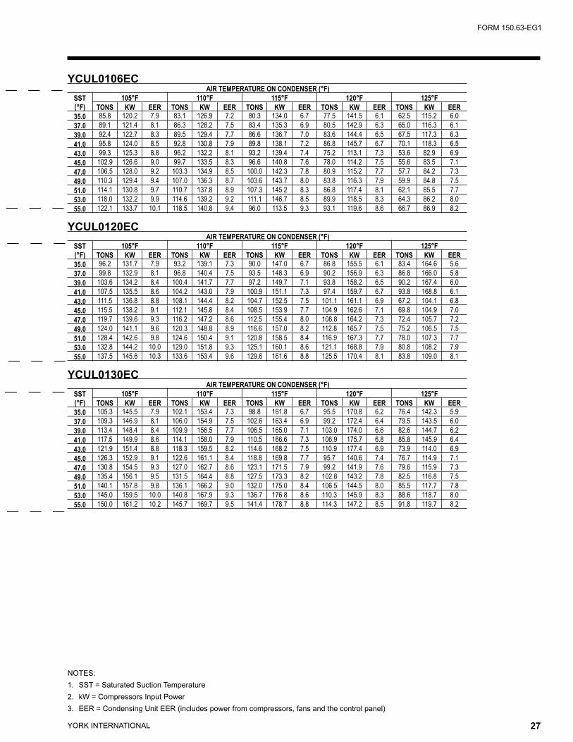
YORK INTERNATIONAL26 YORK INTERNATIONAL 27
FORM 150.63-EG1
NOTES:1. SST = Saturated Suction Temperature2. kW = Compressors Input Power3. EER = Condensing Unit EER (includes power from compressors, fans and the control panel)
YCUL0106EC AIR TEMPERATURE ON CONDENSER (°F)
SST(°F)
105°F 110°F 115°F 120°F 125°FTONS KW EER TONS KW EER TONS KW EER TONS KW EER TONS KW EER
35.0 85.8 120.2 7.9 83.1 126.9 7.2 80.3 134.0 6.7 77.5 141.5 6.1 62.5 115.2 6.037.0 89.1 121.4 8.1 86.3 128.2 7.5 83.4 135.3 6.9 80.5 142.9 6.3 65.0 116.3 6.139.0 92.4 122.7 8.3 89.5 129.4 7.7 86.6 136.7 7.0 83.6 144.4 6.5 67.5 117.3 6.341.0 95.8 124.0 8.5 92.8 130.8 7.9 89.8 138.1 7.2 86.8 145.7 6.7 70.1 118.3 6.543.0 99.3 125.3 8.8 96.2 132.2 8.1 93.2 139.4 7.4 75.2 113.1 7.3 53.6 82.9 6.945.0 102.9 126.6 9.0 99.7 133.5 8.3 96.6 140.8 7.6 78.0 114.2 7.5 55.6 83.5 7.147.0 106.5 128.0 9.2 103.3 134.9 8.5 100.0 142.3 7.8 80.9 115.2 7.7 57.7 84.2 7.349.0 110.3 129.4 9.4 107.0 136.3 8.7 103.6 143.7 8.0 83.8 116.3 7.9 59.9 84.8 7.551.0 114.1 130.8 9.7 110.7 137.8 8.9 107.3 145.2 8.3 86.8 117.4 8.1 62.1 85.5 7.753.0 118.0 132.2 9.9 114.6 139.2 9.2 111.1 146.7 8.5 89.9 118.5 8.3 64.3 86.2 8.055.0 122.1 133.7 10.1 118.5 140.8 9.4 96.0 113.5 9.3 93.1 119.6 8.6 66.7 86.9 8.2
YCUL0120EC AIR TEMPERATURE ON CONDENSER (°F)
SST(°F)
105°F 110°F 115°F 120°F 125°FTONS KW EER TONS KW EER TONS KW EER TONS KW EER TONS KW EER
35.0 96.2 131.7 7.9 93.2 139.1 7.3 90.0 147.0 6.7 86.8 155.5 6.1 83.4 164.6 5.637.0 99.8 132.9 8.1 96.8 140.4 7.5 93.5 148.3 6.9 90.2 156.9 6.3 86.8 166.0 5.839.0 103.6 134.2 8.4 100.4 141.7 7.7 97.2 149.7 7.1 93.8 158.2 6.5 90.2 167.4 6.041.0 107.5 135.5 8.6 104.2 143.0 7.9 100.9 151.1 7.3 97.4 159.7 6.7 93.8 168.8 6.143.0 111.5 136.8 8.8 108.1 144.4 8.2 104.7 152.5 7.5 101.1 161.1 6.9 67.2 104.1 6.845.0 115.5 138.2 9.1 112.1 145.8 8.4 108.5 153.9 7.7 104.9 162.6 7.1 69.8 104.9 7.047.0 119.7 139.6 9.3 116.2 147.2 8.6 112.5 155.4 8.0 108.8 164.2 7.3 72.4 105.7 7.249.0 124.0 141.1 9.6 120.3 148.8 8.9 116.6 157.0 8.2 112.8 165.7 7.5 75.2 106.5 7.551.0 128.4 142.6 9.8 124.6 150.4 9.1 120.8 158.5 8.4 116.9 167.3 7.7 78.0 107.3 7.753.0 132.8 144.2 10.0 129.0 151.8 9.3 125.1 160.1 8.6 121.1 168.8 7.9 80.8 108.2 7.955.0 137.5 145.6 10.3 133.6 153.4 9.6 129.6 161.6 8.8 125.5 170.4 8.1 83.8 109.0 8.1
YCUL0130EC AIR TEMPERATURE ON CONDENSER (°F)
SST(°F)
105°F 110°F 115°F 120°F 125°FTONS KW EER TONS KW EER TONS KW EER TONS KW EER TONS KW EER
35.0 105.3 145.5 7.9 102.1 153.4 7.3 98.8 161.8 6.7 95.5 170.8 6.2 76.4 142.3 5.937.0 109.3 146.9 8.1 106.0 154.9 7.5 102.6 163.4 6.9 99.2 172.4 6.4 79.5 143.5 6.039.0 113.4 148.4 8.4 109.9 156.5 7.7 106.5 165.0 7.1 103.0 174.0 6.6 82.6 144.7 6.241.0 117.5 149.9 8.6 114.1 158.0 7.9 110.5 166.6 7.3 106.9 175.7 6.8 85.8 145.9 6.443.0 121.9 151.4 8.8 118.3 159.5 8.2 114.6 168.2 7.5 110.9 177.4 6.9 73.9 114.0 6.945.0 126.3 152.9 9.1 122.6 161.1 8.4 118.8 169.8 7.7 95.7 140.6 7.4 76.7 114.9 7.147.0 130.8 154.5 9.3 127.0 162.7 8.6 123.1 171.5 7.9 99.2 141.9 7.6 79.6 115.9 7.349.0 135.4 156.1 9.5 131.5 164.4 8.8 127.5 173.3 8.2 102.8 143.2 7.8 82.5 116.8 7.551.0 140.1 157.8 9.8 136.1 166.2 9.0 132.0 175.0 8.4 106.5 144.5 8.0 85.5 117.7 7.853.0 145.0 159.5 10.0 140.8 167.9 9.3 136.7 176.8 8.6 110.3 145.9 8.3 88.6 118.7 8.055.0 150.0 161.2 10.2 145.7 169.7 9.5 141.4 178.7 8.8 114.3 147.2 8.5 91.8 119.7 8.2
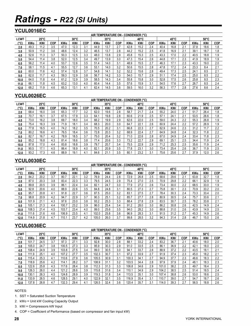
YORK INTERNATIONAL28 YORK INTERNATIONAL 29
FORM 150.63-EG1
Ratings - R22 (SI Units)
NOTES:1. SST = Saturated Suction Temperature2. kWo = Unit kW Cooling Capacity Output3. kWi = Compressors kW Input4. COP = Coefficient of Performance (based on compressor and fan input kW)
YCUL0016EC AIR TEMPERATURE ON - CONDENSER (°C)
LCWT(°C)
25°C 30°C 35°C 40°C 45°C 50°CKWo KWi COP KWo KWi COP KWo KWi COP KWo KWi COP KWo KWi COP KWo KWi COP
2.0 49.3 11.2 3.5 47.0 12.3 3.1 44.9 13.7 2.7 42.8 15.2 2.4 40.4 16.8 2.1 37.8 18.6 1.83.0 50.9 11.2 3.6 48.6 12.4 3.2 46.5 13.7 2.8 44.2 15.2 2.5 41.8 16.9 2.1 39.1 18.7 1.84.0 52.6 11.3 3.7 50.3 12.5 3.3 48.0 13.8 2.9 45.8 15.3 2.5 43.3 17.0 2.2 40.5 18.8 1.95.0 54.4 11.4 3.8 52.0 12.5 3.4 49.7 13.9 3.0 47.3 15.4 2.6 44.8 17.1 2.3 41.9 18.9 1.96.0 56.2 11.4 4.0 53.7 12.6 3.5 51.4 14.0 3.1 48.9 15.5 2.7 46.3 17.1 2.3 43.3 19.0 2.07.0 58.1 11.5 4.1 55.5 12.7 3.6 53.1 14.0 3.2 50.6 15.5 2.8 47.8 17.2 2.4 23.3 8.4 2.18.0 60.0 11.6 4.2 57.4 12.8 3.7 54.8 14.1 3.2 52.2 15.6 2.8 49.4 17.3 2.5 24.1 8.5 2.19.0 62.0 11.7 4.3 59.3 12.9 3.8 56.7 14.2 3.3 54.0 15.7 2.9 51.1 17.4 2.5 25.0 8.5 2.2
10.0 64.0 11.8 4.4 61.2 12.9 3.9 58.5 14.3 3.4 55.8 15.8 3.0 52.8 17.5 2.6 25.8 8.5 2.311.0 66.1 11.8 4.5 63.2 13.0 4.0 60.4 14.4 3.5 57.6 15.9 3.1 54.5 17.6 2.7 26.7 8.5 2.412.0 68.2 11.9 4.6 65.3 13.1 4.1 62.4 14.5 3.6 59.5 16.0 3.2 56.3 17.7 2.8 27.6 8.6 2.4
YCUL0026EC AIR TEMPERATURE ON - CONDENSER (°C)
LCWT(°C)
25°C 30°C 35°C 40°C 45°C 50°CKWo KWi COP KWo KWi COP KWo KWi COP KWo KWi COP KWo KWi COP KWo KWi COP
2.0 68.4 16.0 3.6 65.3 17.7 3.2 62.0 19.6 2.8 58.7 21.7 2.4 55.2 24.0 2.1 51.7 26.4 1.83.0 70.7 16.1 3.7 67.5 17.9 3.3 64.1 19.8 2.8 60.6 21.9 2.5 57.1 24.1 2.1 53.5 26.6 1.84.0 73.0 16.2 3.8 69.7 18.0 3.4 66.2 19.9 2.9 62.6 22.0 2.5 59.0 24.3 2.2 55.3 26.8 1.95.0 75.4 16.3 3.9 71.9 18.1 3.4 68.3 20.0 3.0 64.7 22.1 2.6 60.9 24.4 2.2 57.2 26.9 1.96.0 77.8 16.5 4.0 74.2 18.2 3.5 70.5 20.2 3.1 66.8 22.3 2.7 62.9 24.6 2.3 31.2 11.7 2.27.0 80.2 16.6 4.1 76.5 18.4 3.6 72.8 20.3 3.2 68.9 22.4 2.7 64.9 24.8 2.4 32.3 11.8 2.28.0 82.7 16.7 4.2 78.9 18.5 3.7 75.0 20.4 3.2 71.0 22.6 2.8 67.0 24.9 2.4 33.4 11.8 2.39.0 85.2 16.8 4.3 81.4 18.6 3.8 77.4 20.6 3.3 73.2 22.7 2.9 69.1 25.1 2.5 34.4 11.9 2.4
10.0 87.8 17.0 4.4 83.8 18.8 3.9 79.7 20.7 3.4 75.5 22.9 2.9 71.2 25.3 2.5 35.6 11.9 2.411.0 90.5 17.1 4.5 86.4 18.9 4.0 82.1 20.9 3.5 77.8 23.1 3.0 73.4 25.4 2.6 36.7 11.9 2.512.0 93.2 17.3 4.6 88.9 19.1 4.1 84.6 21.1 3.5 80.1 23.2 3.1 75.6 25.6 2.7 37.9 12.0 2.6
YCUL0030EC AIR TEMPERATURE ON - CONDENSER (°C)
LCWT(°C)
25°C 30°C 35°C 40°C 45°C 50°CKWo KWi COP KWo KWi COP KWo KWi COP KWo KWi COP KWo KWi COP KWo KWi COP
2.0 84.2 20.2 3.7 80.7 22.1 3.2 76.9 24.4 2.8 72.9 26.8 2.5 68.6 29.6 2.1 63.8 32.7 1.83.0 87.0 20.3 3.8 83.4 22.3 3.3 79.5 24.5 2.9 75.4 27.0 2.5 70.9 29.8 2.2 66.1 32.9 1.94.0 89.8 20.5 3.9 86.1 22.4 3.4 82.1 24.7 3.0 77.9 27.2 2.6 73.4 30.0 2.2 68.5 33.0 1.95.0 92.8 20.6 4.0 88.9 22.6 3.5 84.8 24.8 3.1 80.5 27.3 2.7 75.8 30.1 2.3 70.9 33.2 2.06.0 95.7 20.8 4.1 91.8 22.7 3.6 87.5 25.0 3.2 83.1 27.5 2.7 78.4 30.3 2.4 73.3 33.4 2.07.0 98.8 20.9 4.2 94.7 22.9 3.7 90.3 25.1 3.2 85.7 27.7 2.8 80.9 30.5 2.4 75.7 33.6 2.18.0 101.9 21.1 4.3 97.6 23.0 3.8 93.2 25.3 3.3 88.4 27.8 2.9 83.5 30.7 2.5 78.2 33.8 2.19.0 105.1 21.3 4.4 100.7 23.2 3.9 96.0 25.4 3.4 91.2 28.0 3.0 86.2 30.8 2.6 42.5 14.9 2.4
10.0 108.3 21.4 4.5 103.7 23.4 4.0 99.0 25.6 3.5 94.0 28.2 3.0 88.8 31.0 2.6 43.9 14.9 2.511.0 111.6 21.6 4.6 106.9 23.5 4.1 102.0 25.8 3.6 96.9 28.3 3.1 91.5 31.2 2.7 45.3 14.9 2.612.0 114.9 21.8 4.7 110.1 23.7 4.2 105.0 26.0 3.7 99.8 28.5 3.2 94.3 31.4 2.8 46.7 15.0 2.6
YCUL0036EC AIR TEMPERATURE ON - CONDENSER (°C)
LCWT(°C)
25°C 30°C 35°C 40°C 45°C 50°CKWo KWi COP KWo KWi COP KWo KWi COP KWo KWi COP KWo KWi COP KWo KWi COP
2.0 101.7 24.5 3.7 97.3 27.1 3.3 92.8 30.0 2.8 88.1 33.2 2.4 83.2 36.7 2.1 40.6 18.0 2.03.0 105.0 24.7 3.8 100.5 27.3 3.3 95.9 30.3 2.9 91.0 33.5 2.5 86.1 36.9 2.2 42.1 18.0 2.04.0 108.4 24.9 3.9 103.8 27.5 3.4 99.0 30.5 3.0 94.1 33.7 2.6 88.9 37.2 2.2 43.5 18.1 2.15.0 111.9 25.1 4.0 107.2 27.7 3.5 102.3 30.7 3.1 97.2 33.9 2.7 91.9 37.4 2.3 45.0 18.2 2.16.0 115.4 25.3 4.1 110.6 27.9 3.6 105.5 30.9 3.1 100.3 34.1 2.7 94.9 37.7 2.3 46.6 18.3 2.27.0 118.9 25.6 4.2 114.1 28.2 3.7 108.9 31.1 3.2 103.5 34.4 2.8 97.9 37.9 2.4 48.1 18.3 2.38.0 122.6 25.8 4.3 117.6 28.4 3.8 112.3 31.3 3.3 106.8 34.6 2.9 101.0 38.2 2.5 49.7 18.4 2.39.0 126.3 26.0 4.4 121.2 28.6 3.9 115.8 31.6 3.4 110.1 34.9 2.9 104.2 38.5 2.5 51.4 18.5 2.4
10.0 130.1 26.3 4.5 124.8 28.9 3.9 119.3 31.8 3.4 113.5 35.1 3.0 107.4 38.8 2.6 53.0 18.6 2.511.0 133.9 26.5 4.6 128.5 29.1 4.0 122.9 32.1 3.5 116.9 35.4 3.1 110.7 39.0 2.7 54.7 18.7 2.612.0 137.8 26.8 4.7 132.3 29.4 4.1 126.5 32.4 3.6 120.4 35.7 3.1 114.0 39.3 2.7 56.5 18.8 2.6
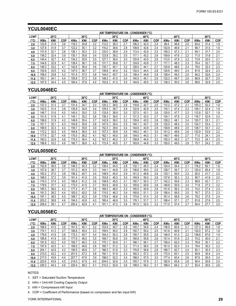
YORK INTERNATIONAL28 YORK INTERNATIONAL 29
FORM 150.63-EG1
NOTES:1. SST = Saturated Suction Temperature2. kWo = Unit kW Cooling Capacity Output3. kWi = Compressors kW Input4. COP = Coefficient of Performance (based on compressor and fan input kW)
YCUL0040EC AIR TEMPERATURE ON - CONDENSER (°C)
LCWT(°C)
25°C 30°C 35°C 40°C 45°C 50°CKWo KWi COP KWo KWi COP KWo KWi COP KWo KWi COP KWo KWi COP KWo KWi COP
2.0 123.8 31.6 3.6 118.3 34.8 3.2 112.5 38.3 2.7 106.2 42.3 2.4 99.4 46.6 2.0 64.4 31.4 1.93.0 127.8 31.9 3.7 122.2 35.1 3.2 116.2 38.6 2.8 109.8 42.6 2.4 102.9 46.9 2.1 66.7 31.5 1.94.0 131.9 32.1 3.8 126.1 35.3 3.3 120.0 38.9 2.9 113.4 42.9 2.5 106.3 47.3 2.1 69.1 31.7 2.05.0 136.2 32.4 3.9 130.1 35.6 3.4 123.8 39.2 3.0 117.1 43.2 2.6 109.9 47.6 2.2 71.5 31.8 2.16.0 140.4 32.7 4.0 134.2 35.9 3.5 127.7 39.4 3.0 120.8 43.5 2.6 113.5 47.9 2.2 73.9 32.0 2.17.0 144.8 32.9 4.1 138.4 36.1 3.6 131.7 39.8 3.1 124.6 43.8 2.7 117.1 48.3 2.3 76.4 32.1 2.28.0 149.3 33.2 4.1 142.6 36.4 3.6 135.7 40.1 3.2 128.5 44.1 2.7 120.8 48.6 2.4 79.0 32.3 2.39.0 153.8 33.5 4.2 147.0 36.7 3.7 139.8 40.4 3.2 132.4 44.4 2.8 124.6 49.0 2.4 81.6 32.4 2.3
10.0 158.4 33.8 4.3 151.4 37.0 3.8 144.0 40.7 3.3 136.4 44.8 2.9 128.4 49.3 2.5 84.2 32.6 2.411.0 163.1 34.1 4.4 155.8 37.3 3.9 148.3 41.0 3.4 140.5 45.1 2.9 132.3 49.7 2.5 86.9 32.7 2.512.0 167.9 34.4 4.5 160.4 37.6 4.0 152.6 41.3 3.5 144.6 45.5 3.0 136.3 50.0 2.6 89.6 32.9 2.5
YCUL0046EC AIR TEMPERATURE ON - CONDENSER (°C)
LCWT(°C)
25°C 30°C 35°C 40°C 45°C 50°CKWo KWi COP KWo KWi COP KWo KWi COP KWo KWi COP KWo KWi COP KWo KWi COP
2.0 137.3 31.3 3.7 131.4 34.7 3.3 125.2 38.5 2.8 118.8 42.7 2.5 112.2 47.2 2.1 105.3 52.2 1.83.0 142.0 31.4 3.8 135.9 34.9 3.4 129.5 38.7 2.9 122.8 42.9 2.5 116.1 47.4 2.2 109.1 52.4 1.94.0 146.7 31.6 4.0 140.4 35.0 3.5 133.9 38.9 3.0 127.0 43.1 2.6 120.0 47.7 2.3 112.9 52.7 1.95.0 151.6 31.8 4.1 145.1 35.2 3.6 138.3 39.0 3.1 131.3 43.3 2.7 124.1 47.9 2.3 116.7 52.9 2.06.0 156.6 31.9 4.2 149.9 35.4 3.7 142.9 39.2 3.2 135.6 43.5 2.8 128.2 48.1 2.4 120.7 53.1 2.17.0 161.7 32.1 4.3 154.8 35.6 3.8 147.5 39.4 3.3 140.1 43.7 2.8 132.5 48.3 2.5 124.7 53.4 2.18.0 166.9 32.3 4.4 159.7 35.8 3.9 152.3 39.6 3.4 144.6 43.9 2.9 136.8 48.6 2.5 128.7 53.7 2.29.0 172.2 32.5 4.5 164.8 36.0 4.0 157.2 39.8 3.5 149.2 44.1 3.0 141.2 48.8 2.6 132.9 53.9 2.2
10.0 177.6 32.7 4.6 170.0 36.2 4.1 162.1 40.0 3.6 154.0 44.3 3.1 145.7 49.0 2.7 71.0 24.1 2.411.0 183.2 32.9 4.8 175.3 36.4 4.2 167.2 40.2 3.7 158.8 44.5 3.2 150.3 49.2 2.7 73.3 24.1 2.512.0 188.8 33.2 4.9 180.7 36.6 4.3 172.4 40.5 3.7 163.8 44.8 3.3 155.0 49.5 2.8 75.7 24.2 2.5
YCUL0050EC AIR TEMPERATURE ON - CONDENSER (°C)
LCWT(°C)
25°C 30°C 35°C 40°C 45°C 50°CKWo KWi COP KWo KWi COP KWo KWi COP KWo KWi COP KWo KWi COP KWo KWi COP
2.0 152.8 36.5 3.6 146.3 40.3 3.2 139.4 44.5 2.8 132.1 49.3 2.4 124.4 54.4 2.1 116.2 60.1 1.83.0 157.9 36.7 3.7 151.2 40.5 3.3 144.1 44.8 2.9 136.6 49.5 2.5 128.7 54.7 2.1 120.4 60.4 1.84.0 163.2 37.0 3.8 156.2 40.7 3.4 148.9 45.0 2.9 141.2 49.8 2.6 133.1 55.0 2.2 92.5 41.7 2.05.0 168.5 37.2 3.9 161.4 41.0 3.5 153.8 45.3 3.0 145.9 50.0 2.6 137.6 55.3 2.3 95.7 41.9 2.06.0 174.0 37.4 4.0 166.6 41.2 3.6 158.8 45.5 3.1 150.7 50.3 2.7 142.2 55.6 2.3 98.9 42.1 2.17.0 179.6 37.7 4.2 172.0 41.5 3.7 163.9 45.8 3.2 155.6 50.6 2.8 146.8 55.9 2.4 71.8 27.3 2.28.0 185.3 38.0 4.3 177.4 41.7 3.8 169.2 46.0 3.3 160.5 50.9 2.8 151.6 56.2 2.5 74.2 27.4 2.39.0 191.2 38.2 4.4 183.0 42.0 3.8 174.5 46.3 3.4 165.6 51.1 2.9 156.4 56.5 2.5 76.7 27.5 2.3
10.0 197.1 38.5 4.5 188.7 42.3 3.9 179.9 46.6 3.5 170.8 51.4 3.0 161.4 56.8 2.6 79.2 27.5 2.411.0 203.2 38.8 4.6 194.5 42.6 4.0 185.4 46.9 3.5 176.1 51.7 3.1 166.4 57.1 2.7 81.8 27.6 2.512.0 209.4 39.1 4.7 200.4 42.9 4.1 191.1 47.2 3.6 181.5 52.0 3.2 171.5 57.4 2.7 84.4 27.7 2.5
YCUL0056EC AIR TEMPERATURE ON - CONDENSER (°C)
LCWT(°C)
25°C 30°C 35°C 40°C 45°C 50°CKWo KWi COP KWo KWi COP KWo KWi COP KWo KWi COP KWo KWi COP KWo KWi COP
2.0 168.5 41.0 3.6 161.5 45.1 3.2 153.9 49.7 2.8 145.7 54.9 2.4 136.9 60.6 2.1 127.3 66.8 1.83.0 174.1 41.3 3.7 166.8 45.4 3.3 159.0 50.0 2.9 150.7 55.2 2.5 141.6 60.9 2.1 132.0 67.2 1.84.0 179.9 41.6 3.8 172.3 45.7 3.4 164.3 50.3 2.9 155.7 55.5 2.6 146.5 61.3 2.2 136.6 67.6 1.95.0 185.8 41.9 3.9 177.9 46.0 3.5 169.7 50.6 3.0 160.8 55.8 2.6 151.4 61.6 2.3 74.2 30.0 2.16.0 191.8 42.2 4.0 183.7 46.3 3.5 175.1 50.9 3.1 166.1 56.1 2.7 156.4 62.0 2.3 76.8 30.1 2.27.0 197.9 42.5 4.1 189.5 46.6 3.6 180.7 51.2 3.2 171.4 56.5 2.8 161.5 62.3 2.4 79.4 30.2 2.28.0 204.1 42.9 4.2 195.5 46.9 3.7 186.3 51.6 3.3 176.8 56.8 2.8 166.7 62.7 2.4 82.1 30.3 2.39.0 210.5 43.2 4.3 201.5 47.2 3.8 192.1 51.9 3.3 182.3 57.2 2.9 172.0 63.1 2.5 84.8 30.4 2.4
10.0 217.0 43.6 4.4 207.7 47.6 3.9 198.0 52.2 3.4 188.0 57.5 3.0 177.4 63.4 2.6 87.6 30.5 2.411.0 223.6 43.9 4.5 214.0 47.9 4.0 204.0 52.6 3.5 193.7 57.9 3.1 182.9 63.8 2.6 90.4 30.6 2.512.0 230.3 44.3 4.6 220.4 48.3 4.1 210.2 52.9 3.6 199.5 58.2 3.1 188.4 64.2 2.7 93.4 30.6 2.6
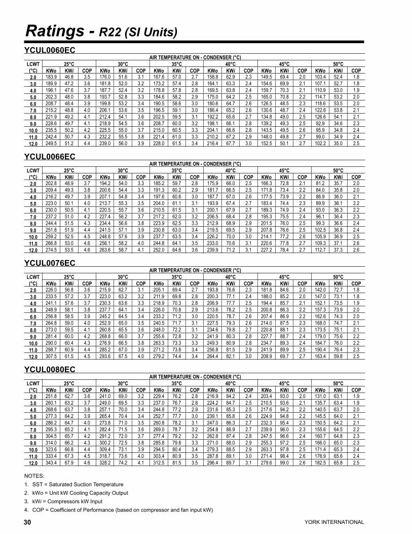
YORK INTERNATIONAL30 YORK INTERNATIONAL 31
FORM 150.63-EG1
Ratings - R22 (SI Units)
NOTES:1. SST = Saturated Suction Temperature2. kWo = Unit kW Cooling Capacity Output3. kWi = Compressors kW Input4. COP = Coefficient of Performance (based on compressor and fan input kW)
YCUL0060EC AIR TEMPERATURE ON - CONDENSER (°C)
LCWT(°C)
25°C 30°C 35°C 40°C 45°C 50°CKWo KWi COP KWo KWi COP KWo KWi COP KWo KWi COP KWo KWi COP KWo KWi COP
2.0 183.9 46.8 3.5 176.0 51.6 3.1 167.6 57.0 2.7 158.8 62.9 2.3 149.5 69.4 2.0 103.4 52.4 1.83.0 189.9 47.2 3.6 181.8 52.0 3.2 173.2 57.4 2.8 164.1 63.3 2.4 154.6 69.9 2.1 107.1 52.7 1.84.0 196.1 47.6 3.7 187.7 52.4 3.2 178.8 57.8 2.8 169.5 63.8 2.4 159.7 70.3 2.1 110.9 53.0 1.95.0 202.3 48.0 3.8 193.7 52.8 3.3 184.6 58.2 2.9 175.0 64.2 2.5 165.0 70.8 2.2 114.7 53.2 2.06.0 208.7 48.4 3.9 199.8 53.2 3.4 190.5 58.6 3.0 180.6 64.7 2.6 126.5 48.5 2.3 118.6 53.5 2.07.0 215.2 48.8 4.0 206.1 53.6 3.5 196.5 59.1 3.0 186.4 65.2 2.6 130.6 48.7 2.4 122.6 53.8 2.18.0 221.9 49.2 4.1 212.4 54.1 3.6 202.5 59.5 3.1 192.2 65.6 2.7 134.8 49.0 2.5 126.6 54.1 2.19.0 228.6 49.7 4.1 218.9 54.5 3.6 208.7 60.0 3.2 198.1 66.1 2.8 139.2 49.3 2.5 92.9 34.6 2.3
10.0 235.5 50.2 4.2 225.5 55.0 3.7 215.0 60.5 3.3 204.1 66.6 2.8 143.5 49.5 2.6 95.9 34.8 2.411.0 242.4 50.7 4.3 232.2 55.5 3.8 221.4 61.0 3.3 210.2 67.2 2.9 148.0 49.8 2.7 99.0 34.9 2.412.0 249.5 51.2 4.4 239.0 56.0 3.9 228.0 61.5 3.4 216.4 67.7 3.0 152.5 50.1 2.7 102.2 35.0 2.5
YCUL0066EC AIR TEMPERATURE ON - CONDENSER (°C)
LCWT(°C)
25°C 30°C 35°C 40°C 45°C 50°CKWo KWi COP KWo KWi COP KWo KWi COP KWo KWi COP KWo KWi COP KWo KWi COP
2.0 202.8 48.9 3.7 194.2 54.0 3.3 185.2 59.7 2.8 175.9 66.0 2.5 166.3 72.8 2.1 81.2 35.7 2.03.0 209.4 49.3 3.8 200.6 54.4 3.3 191.3 60.2 2.9 181.7 66.5 2.5 171.8 73.4 2.2 84.0 35.8 2.04.0 216.2 49.7 3.9 207.1 54.8 3.4 197.6 60.6 3.0 187.7 67.0 2.6 177.5 73.9 2.2 86.9 36.0 2.15.0 223.0 50.1 4.0 213.7 55.3 3.5 204.0 61.1 3.1 193.9 67.4 2.7 183.4 74.4 2.3 89.9 36.1 2.26.0 230.0 50.5 4.1 220.5 55.7 3.6 210.5 61.5 3.1 200.1 67.9 2.7 189.3 74.9 2.4 93.0 36.3 2.27.0 237.2 51.0 4.2 227.4 56.2 3.7 217.2 62.0 3.2 206.5 68.4 2.8 195.3 75.5 2.4 96.1 36.4 2.38.0 244.4 51.5 4.3 234.4 56.6 3.8 223.9 62.5 3.3 212.9 68.9 2.9 201.5 76.0 2.5 99.3 36.6 2.49.0 251.8 51.9 4.4 241.5 57.1 3.9 230.8 63.0 3.4 219.5 69.5 2.9 207.8 76.6 2.5 102.5 36.8 2.4
10.0 259.2 52.5 4.5 248.8 57.6 3.9 237.7 63.5 3.4 226.2 70.0 3.0 214.1 77.2 2.6 105.9 36.9 2.511.0 266.8 53.0 4.6 256.1 58.2 4.0 244.8 64.1 3.5 233.0 70.6 3.1 220.6 77.8 2.7 109.3 37.1 2.612.0 274.5 53.5 4.6 263.6 58.7 4.1 252.0 64.6 3.6 239.9 71.2 3.1 227.2 78.4 2.7 112.7 37.3 2.6
YCUL0076EC AIR TEMPERATURE ON - CONDENSER (°C)
LCWT(°C)
25°C 30°C 35°C 40°C 45°C 50°CKWo KWi COP KWo KWi COP KWo KWi COP KWo KWi COP KWo KWi COP KWo KWi COP
2.0 226.0 56.8 3.6 215.9 62.7 3.1 205.1 69.4 2.7 193.8 76.6 2.3 181.8 84.6 2.0 142.0 72.7 1.83.0 233.5 57.2 3.7 223.0 63.2 3.2 211.9 69.8 2.8 200.3 77.1 2.4 188.0 85.2 2.0 147.0 73.1 1.84.0 241.1 57.6 3.7 230.3 63.6 3.3 218.9 70.3 2.8 206.9 77.7 2.5 194.4 85.7 2.1 152.1 73.5 1.95.0 248.9 58.1 3.8 237.7 64.1 3.4 226.0 70.8 2.9 213.6 78.2 2.5 200.8 86.3 2.2 157.3 73.9 2.06.0 256.8 58.5 3.9 245.2 64.5 3.4 233.2 71.2 3.0 220.5 78.7 2.6 207.4 86.9 2.2 162.6 74.3 2.07.0 264.8 59.0 4.0 252.9 65.0 3.5 240.5 71.7 3.1 227.5 79.3 2.6 214.0 87.5 2.3 168.0 74.7 2.18.0 273.0 59.5 4.1 260.8 65.5 3.6 248.0 72.2 3.1 234.6 79.8 2.7 220.8 88.1 2.3 173.5 75.1 2.19.0 281.4 60.0 4.2 268.8 66.0 3.7 255.6 72.8 3.2 241.9 80.3 2.8 227.7 88.7 2.4 179.0 75.6 2.2
10.0 290.0 60.4 4.3 276.9 66.5 3.8 263.3 73.3 3.3 249.3 80.9 2.8 234.7 89.3 2.4 184.7 76.0 2.211.0 298.7 60.9 4.4 285.2 67.0 3.9 271.2 73.8 3.4 256.8 81.5 2.9 241.9 89.9 2.5 190.4 76.4 2.312.0 307.5 61.5 4.5 293.6 67.5 4.0 279.2 74.4 3.4 264.4 82.1 3.0 208.9 69.7 2.7 163.4 59.8 2.5
YCUL0080EC AIR TEMPERATURE ON - CONDENSER (°C)
LCWT(°C)
25°C 30°C 35°C 40°C 45°C 50°CKWo KWi COP KWo KWi COP KWo KWi COP KWo KWi COP KWo KWi COP KWo KWi COP
2.0 251.8 62.7 3.6 241.0 69.0 3.2 229.4 76.2 2.8 216.9 84.2 2.4 203.4 93.0 2.0 131.0 63.1 1.93.0 260.1 63.2 3.7 249.0 69.5 3.3 237.0 76.7 2.8 224.2 84.7 2.5 210.5 93.6 2.1 135.7 63.4 1.94.0 268.6 63.7 3.8 257.1 70.0 3.4 244.8 77.2 2.9 231.6 85.3 2.5 217.6 94.2 2.2 140.5 63.7 2.05.0 277.3 64.2 3.9 265.4 70.4 3.4 252.7 77.7 3.0 239.1 85.8 2.6 224.9 94.8 2.2 145.5 64.0 2.16.0 286.2 64.7 4.0 273.8 71.0 3.5 260.8 78.2 3.1 247.0 86.3 2.7 232.3 95.4 2.3 150.5 64.2 2.17.0 295.3 65.2 4.1 282.4 71.5 3.6 269.0 78.7 3.2 254.8 86.9 2.7 239.9 96.0 2.3 155.6 64.5 2.28.0 304.5 65.7 4.2 291.2 72.0 3.7 277.4 79.2 3.2 262.8 87.4 2.8 247.5 96.6 2.4 160.7 64.8 2.39.0 314.0 66.2 4.3 300.2 72.5 3.8 285.8 79.8 3.3 271.0 88.0 2.9 255.3 97.2 2.5 166.0 65.0 2.3
10.0 323.6 66.8 4.4 309.4 73.1 3.9 294.5 80.4 3.4 279.3 88.5 2.9 263.3 97.8 2.5 171.4 65.3 2.411.0 333.4 67.3 4.5 318.7 73.6 4.0 303.4 80.9 3.5 287.8 89.1 3.0 271.4 98.4 2.6 176.9 65.6 2.412.0 343.4 67.9 4.6 328.2 74.2 4.1 312.5 81.5 3.5 296.4 89.7 3.1 279.6 99.0 2.6 182.5 65.8 2.5
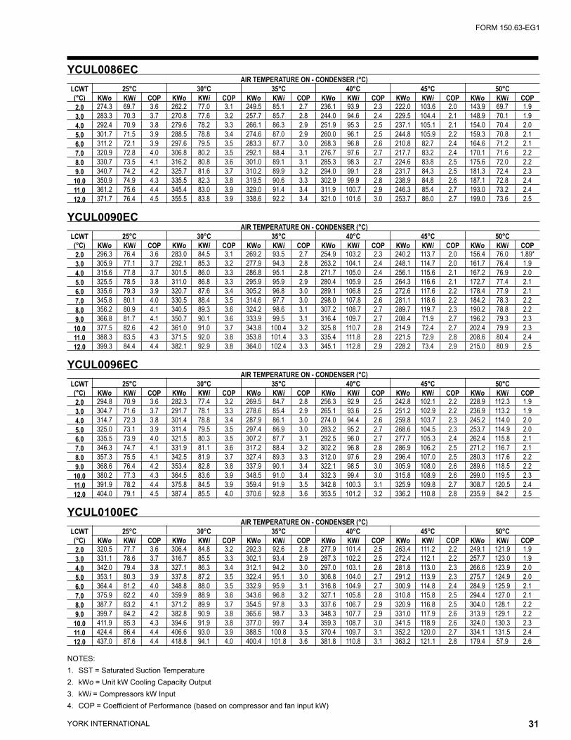
YORK INTERNATIONAL30 YORK INTERNATIONAL 31
FORM 150.63-EG1
NOTES:1. SST = Saturated Suction Temperature2. kWo = Unit kW Cooling Capacity Output3. kWi = Compressors kW Input4. COP = Coefficient of Performance (based on compressor and fan input kW)
YCUL0086EC AIR TEMPERATURE ON - CONDENSER (°C)
LCWT(°C)
25°C 30°C 35°C 40°C 45°C 50°CKWo KWi COP KWo KWi COP KWo KWi COP KWo KWi COP KWo KWi COP KWo KWi COP
2.0 274.3 69.7 3.6 262.2 77.0 3.1 249.5 85.1 2.7 236.1 93.9 2.3 222.0 103.6 2.0 143.9 69.7 1.93.0 283.3 70.3 3.7 270.8 77.6 3.2 257.7 85.7 2.8 244.0 94.6 2.4 229.5 104.4 2.1 148.9 70.1 1.94.0 292.4 70.9 3.8 279.6 78.2 3.3 266.1 86.3 2.9 251.9 95.3 2.5 237.1 105.1 2.1 154.0 70.4 2.05.0 301.7 71.5 3.9 288.5 78.8 3.4 274.6 87.0 2.9 260.0 96.1 2.5 244.8 105.9 2.2 159.3 70.8 2.16.0 311.2 72.1 3.9 297.6 79.5 3.5 283.3 87.7 3.0 268.3 96.8 2.6 210.8 82.7 2.4 164.6 71.2 2.17.0 320.9 72.8 4.0 306.8 80.2 3.5 292.1 88.4 3.1 276.7 97.6 2.7 217.7 83.2 2.4 170.1 71.6 2.28.0 330.7 73.5 4.1 316.2 80.8 3.6 301.0 89.1 3.1 285.3 98.3 2.7 224.6 83.8 2.5 175.6 72.0 2.29.0 340.7 74.2 4.2 325.7 81.6 3.7 310.2 89.9 3.2 294.0 99.1 2.8 231.7 84.3 2.5 181.3 72.4 2.3
10.0 350.9 74.9 4.3 335.5 82.3 3.8 319.5 90.6 3.3 302.9 99.9 2.8 238.9 84.8 2.6 187.1 72.8 2.411.0 361.2 75.6 4.4 345.4 83.0 3.9 329.0 91.4 3.4 311.9 100.7 2.9 246.3 85.4 2.7 193.0 73.2 2.412.0 371.7 76.4 4.5 355.5 83.8 3.9 338.6 92.2 3.4 321.0 101.6 3.0 253.7 86.0 2.7 199.0 73.6 2.5
YCUL0090EC AIR TEMPERATURE ON - CONDENSER (°C)
LCWT(°C)
25°C 30°C 35°C 40°C 45°C 50°CKWo KWi COP KWo KWi COP KWo KWi COP KWo KWi COP KWo KWi COP KWo KWi COP
2.0 296.3 76.4 3.6 283.0 84.5 3.1 269.2 93.5 2.7 254.9 103.2 2.3 240.2 113.7 2.0 156.4 76.0 1.89*3.0 305.9 77.1 3.7 292.1 85.3 3.2 277.9 94.3 2.8 263.2 104.1 2.4 248.1 114.7 2.0 161.7 76.4 1.94.0 315.6 77.8 3.7 301.5 86.0 3.3 286.8 95.1 2.8 271.7 105.0 2.4 256.1 115.6 2.1 167.2 76.9 2.05.0 325.5 78.5 3.8 311.0 86.8 3.3 295.9 95.9 2.9 280.4 105.9 2.5 264.3 116.6 2.1 172.7 77.4 2.16.0 335.6 79.3 3.9 320.7 87.6 3.4 305.2 96.8 3.0 289.1 106.8 2.5 272.6 117.6 2.2 178.4 77.9 2.17.0 345.8 80.1 4.0 330.5 88.4 3.5 314.6 97.7 3.0 298.0 107.8 2.6 281.1 118.6 2.2 184.2 78.3 2.28.0 356.2 80.9 4.1 340.5 89.3 3.6 324.2 98.6 3.1 307.2 108.7 2.7 289.7 119.7 2.3 190.2 78.8 2.29.0 366.8 81.7 4.1 350.7 90.1 3.6 333.9 99.5 3.1 316.4 109.7 2.7 208.4 71.9 2.7 196.2 79.3 2.3
10.0 377.5 82.6 4.2 361.0 91.0 3.7 343.8 100.4 3.2 325.8 110.7 2.8 214.9 72.4 2.7 202.4 79.9 2.311.0 388.3 83.5 4.3 371.5 92.0 3.8 353.8 101.4 3.3 335.4 111.8 2.8 221.5 72.9 2.8 208.6 80.4 2.412.0 399.3 84.4 4.4 382.1 92.9 3.8 364.0 102.4 3.3 345.1 112.8 2.9 228.2 73.4 2.9 215.0 80.9 2.5
YCUL0096EC AIR TEMPERATURE ON - CONDENSER (°C)
LCWT(°C)
25°C 30°C 35°C 40°C 45°C 50°CKWo KWi COP KWo KWi COP KWo KWi COP KWo KWi COP KWo KWi COP KWo KWi COP
2.0 294.8 70.9 3.6 282.3 77.4 3.2 269.5 84.7 2.8 256.3 92.9 2.5 242.8 102.1 2.2 228.9 112.3 1.93.0 304.7 71.6 3.7 291.7 78.1 3.3 278.6 85.4 2.9 265.1 93.6 2.5 251.2 102.9 2.2 236.9 113.2 1.94.0 314.7 72.3 3.8 301.4 78.8 3.4 287.9 86.1 3.0 274.0 94.4 2.6 259.8 103.7 2.3 245.2 114.0 2.05.0 325.0 73.1 3.9 311.4 79.5 3.5 297.4 86.9 3.0 283.2 95.2 2.7 268.6 104.5 2.3 253.7 114.9 2.06.0 335.5 73.9 4.0 321.5 80.3 3.5 307.2 87.7 3.1 292.5 96.0 2.7 277.7 105.3 2.4 262.4 115.8 2.17.0 346.3 74.7 4.1 331.9 81.1 3.6 317.2 88.4 3.2 302.2 96.8 2.8 286.9 106.2 2.5 271.2 116.7 2.18.0 357.3 75.5 4.1 342.5 81.9 3.7 327.4 89.3 3.3 312.0 97.6 2.9 296.4 107.0 2.5 280.3 117.6 2.29.0 368.6 76.4 4.2 353.4 82.8 3.8 337.9 90.1 3.4 322.1 98.5 3.0 305.9 108.0 2.6 289.6 118.5 2.2
10.0 380.2 77.3 4.3 364.5 83.6 3.9 348.5 91.0 3.4 332.3 99.4 3.0 315.8 108.9 2.6 299.0 119.5 2.311.0 391.9 78.2 4.4 375.8 84.5 3.9 359.4 91.9 3.5 342.8 100.3 3.1 325.9 109.8 2.7 308.7 120.5 2.412.0 404.0 79.1 4.5 387.4 85.5 4.0 370.6 92.8 3.6 353.5 101.2 3.2 336.2 110.8 2.8 235.9 84.2 2.5
YCUL0100EC AIR TEMPERATURE ON - CONDENSER (°C)
LCWT(°C)
25°C 30°C 35°C 40°C 45°C 50°CKWo KWi COP KWo KWi COP KWo KWi COP KWo KWi COP KWo KWi COP KWo KWi COP
2.0 320.5 77.7 3.6 306.4 84.8 3.2 292.3 92.6 2.8 277.9 101.4 2.5 263.4 111.2 2.2 249.1 121.9 1.93.0 331.1 78.6 3.7 316.7 85.5 3.3 302.1 93.4 2.9 287.3 102.2 2.5 272.4 112.1 2.2 257.7 123.0 1.94.0 342.0 79.4 3.8 327.1 86.3 3.4 312.1 94.2 3.0 297.0 103.1 2.6 281.8 113.0 2.3 266.6 123.9 2.05.0 353.1 80.3 3.9 337.8 87.2 3.5 322.4 95.1 3.0 306.8 104.0 2.7 291.2 113.9 2.3 275.7 124.9 2.06.0 364.4 81.2 4.0 348.8 88.0 3.5 332.9 95.9 3.1 316.8 104.9 2.7 300.9 114.8 2.4 284.9 125.9 2.17.0 375.9 82.2 4.0 359.9 88.9 3.6 343.6 96.8 3.2 327.1 105.8 2.8 310.8 115.8 2.5 294.4 127.0 2.18.0 387.7 83.2 4.1 371.2 89.9 3.7 354.5 97.8 3.3 337.6 106.7 2.9 320.9 116.8 2.5 304.0 128.1 2.29.0 399.7 84.2 4.2 382.8 90.9 3.8 365.6 98.7 3.3 348.3 107.7 2.9 331.0 117.9 2.6 313.9 129.1 2.2
10.0 411.9 85.3 4.3 394.6 91.9 3.8 377.0 99.7 3.4 359.3 108.7 3.0 341.5 118.9 2.6 324.0 130.3 2.311.0 424.4 86.4 4.4 406.6 93.0 3.9 388.5 100.8 3.5 370.4 109.7 3.1 352.2 120.0 2.7 334.1 131.5 2.412.0 437.0 87.6 4.4 418.8 94.1 4.0 400.4 101.8 3.6 381.8 110.8 3.1 363.2 121.1 2.8 179.4 57.9 2.6
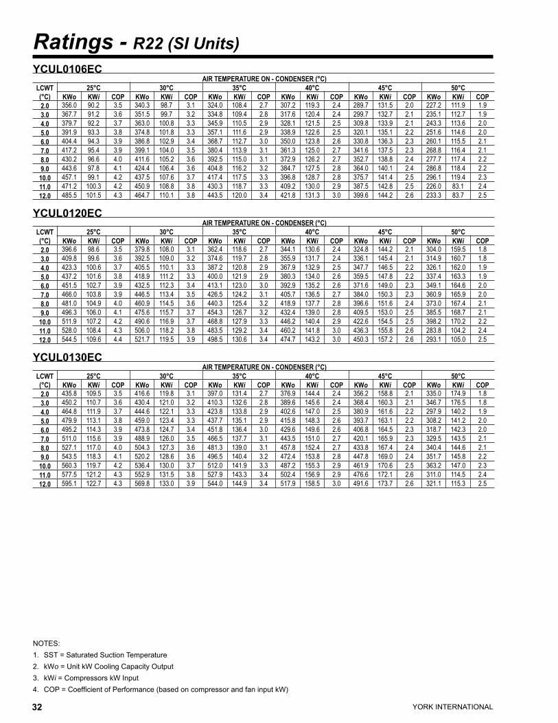
YORK INTERNATIONAL32 YORK INTERNATIONAL 33
FORM 150.63-EG1
Ratings - R22 (SI Units)
NOTES:1. SST = Saturated Suction Temperature2. kWo = Unit kW Cooling Capacity Output3. kWi = Compressors kW Input4. COP = Coefficient of Performance (based on compressor and fan input kW)
YCUL0106EC AIR TEMPERATURE ON - CONDENSER (°C)
LCWT(°C)
25°C 30°C 35°C 40°C 45°C 50°CKWo KWi COP KWo KWi COP KWo KWi COP KWo KWi COP KWo KWi COP KWo KWi COP
2.0 356.0 90.2 3.5 340.3 98.7 3.1 324.0 108.4 2.7 307.2 119.3 2.4 289.7 131.5 2.0 227.2 111.9 1.93.0 367.7 91.2 3.6 351.5 99.7 3.2 334.8 109.4 2.8 317.6 120.4 2.4 299.7 132.7 2.1 235.1 112.7 1.94.0 379.7 92.2 3.7 363.0 100.8 3.3 345.9 110.5 2.9 328.1 121.5 2.5 309.8 133.9 2.1 243.3 113.6 2.05.0 391.9 93.3 3.8 374.8 101.8 3.3 357.1 111.6 2.9 338.9 122.6 2.5 320.1 135.1 2.2 251.6 114.6 2.06.0 404.4 94.3 3.9 386.8 102.9 3.4 368.7 112.7 3.0 350.0 123.8 2.6 330.8 136.3 2.3 260.1 115.5 2.17.0 417.2 95.4 3.9 399.1 104.0 3.5 380.4 113.9 3.1 361.3 125.0 2.7 341.6 137.5 2.3 268.8 116.4 2.18.0 430.2 96.6 4.0 411.6 105.2 3.6 392.5 115.0 3.1 372.9 126.2 2.7 352.7 138.8 2.4 277.7 117.4 2.29.0 443.6 97.8 4.1 424.4 106.4 3.6 404.8 116.2 3.2 384.7 127.5 2.8 364.0 140.1 2.4 286.8 118.4 2.2
10.0 457.1 99.1 4.2 437.5 107.6 3.7 417.4 117.5 3.3 396.8 128.7 2.8 375.7 141.4 2.5 296.1 119.4 2.311.0 471.2 100.3 4.2 450.9 108.8 3.8 430.3 118.7 3.3 409.2 130.0 2.9 387.5 142.8 2.5 226.0 83.1 2.412.0 485.5 101.5 4.3 464.7 110.1 3.8 443.5 120.0 3.4 421.8 131.3 3.0 399.6 144.2 2.6 233.3 83.7 2.5
YCUL0120EC AIR TEMPERATURE ON - CONDENSER (°C)
LCWT(°C)
25°C 30°C 35°C 40°C 45°C 50°CKWo KWi COP KWo KWi COP KWo KWi COP KWo KWi COP KWo KWi COP KWo KWi COP
2.0 396.6 98.6 3.5 379.8 108.0 3.1 362.4 118.6 2.7 344.1 130.6 2.4 324.8 144.2 2.1 304.0 159.5 1.83.0 409.8 99.6 3.6 392.5 109.0 3.2 374.6 119.7 2.8 355.9 131.7 2.4 336.1 145.4 2.1 314.9 160.7 1.84.0 423.3 100.6 3.7 405.5 110.1 3.3 387.2 120.8 2.9 367.9 132.9 2.5 347.7 146.5 2.2 326.1 162.0 1.95.0 437.2 101.6 3.8 418.9 111.2 3.3 400.0 121.9 2.9 380.3 134.0 2.6 359.5 147.8 2.2 337.4 163.3 1.96.0 451.5 102.7 3.9 432.5 112.3 3.4 413.1 123.0 3.0 392.9 135.2 2.6 371.6 149.0 2.3 349.1 164.6 2.07.0 466.0 103.8 3.9 446.5 113.4 3.5 426.5 124.2 3.1 405.7 136.5 2.7 384.0 150.3 2.3 360.9 165.9 2.08.0 481.0 104.9 4.0 460.9 114.5 3.6 440.3 125.4 3.2 418.9 137.7 2.8 396.6 151.6 2.4 373.0 167.4 2.19.0 496.3 106.0 4.1 475.6 115.7 3.7 454.3 126.7 3.2 432.4 139.0 2.8 409.5 153.0 2.5 385.5 168.7 2.1
10.0 511.9 107.2 4.2 490.6 116.9 3.7 468.8 127.9 3.3 446.2 140.4 2.9 422.6 154.5 2.5 398.2 170.2 2.211.0 528.0 108.4 4.3 506.0 118.2 3.8 483.5 129.2 3.4 460.2 141.8 3.0 436.3 155.8 2.6 283.8 104.2 2.412.0 544.5 109.6 4.4 521.7 119.5 3.9 498.5 130.6 3.4 474.7 143.2 3.0 450.3 157.2 2.6 293.1 105.0 2.5
YCUL0130EC AIR TEMPERATURE ON - CONDENSER (°C)
LCWT(°C)
25°C 30°C 35°C 40°C 45°C 50°CKWo KWi COP KWo KWi COP KWo KWi COP KWo KWi COP KWo KWi COP KWo KWi COP
2.0 435.8 109.5 3.5 416.6 119.8 3.1 397.0 131.4 2.7 376.9 144.4 2.4 356.2 158.8 2.1 335.0 174.9 1.83.0 450.2 110.7 3.6 430.4 121.0 3.2 410.3 132.6 2.8 389.6 145.6 2.4 368.4 160.3 2.1 346.7 176.5 1.84.0 464.8 111.9 3.7 444.6 122.1 3.3 423.8 133.8 2.9 402.6 147.0 2.5 380.9 161.6 2.2 297.9 140.2 1.95.0 479.9 113.1 3.8 459.0 123.4 3.3 437.7 135.1 2.9 415.8 148.3 2.6 393.7 163.1 2.2 308.2 141.2 2.06.0 495.2 114.3 3.9 473.8 124.7 3.4 451.8 136.4 3.0 429.6 149.6 2.6 406.8 164.5 2.3 318.7 142.3 2.07.0 511.0 115.6 3.9 488.9 126.0 3.5 466.5 137.7 3.1 443.5 151.0 2.7 420.1 165.9 2.3 329.5 143.5 2.18.0 527.1 117.0 4.0 504.3 127.3 3.6 481.3 139.0 3.1 457.8 152.4 2.7 433.8 167.4 2.4 340.4 144.6 2.19.0 543.5 118.3 4.1 520.2 128.6 3.6 496.5 140.4 3.2 472.4 153.8 2.8 447.8 169.0 2.4 351.7 145.8 2.2
10.0 560.3 119.7 4.2 536.4 130.0 3.7 512.0 141.9 3.3 487.2 155.3 2.9 461.9 170.6 2.5 363.2 147.0 2.311.0 577.5 121.2 4.3 552.9 131.5 3.8 527.9 143.3 3.4 502.4 156.9 2.9 476.6 172.1 2.6 311.0 114.5 2.412.0 595.1 122.7 4.3 569.8 133.0 3.9 544.0 144.9 3.4 517.9 158.5 3.0 491.6 173.7 2.6 321.1 115.3 2.5

YORK INTERNATIONAL32 YORK INTERNATIONAL 33
FORM 150.63-EG1
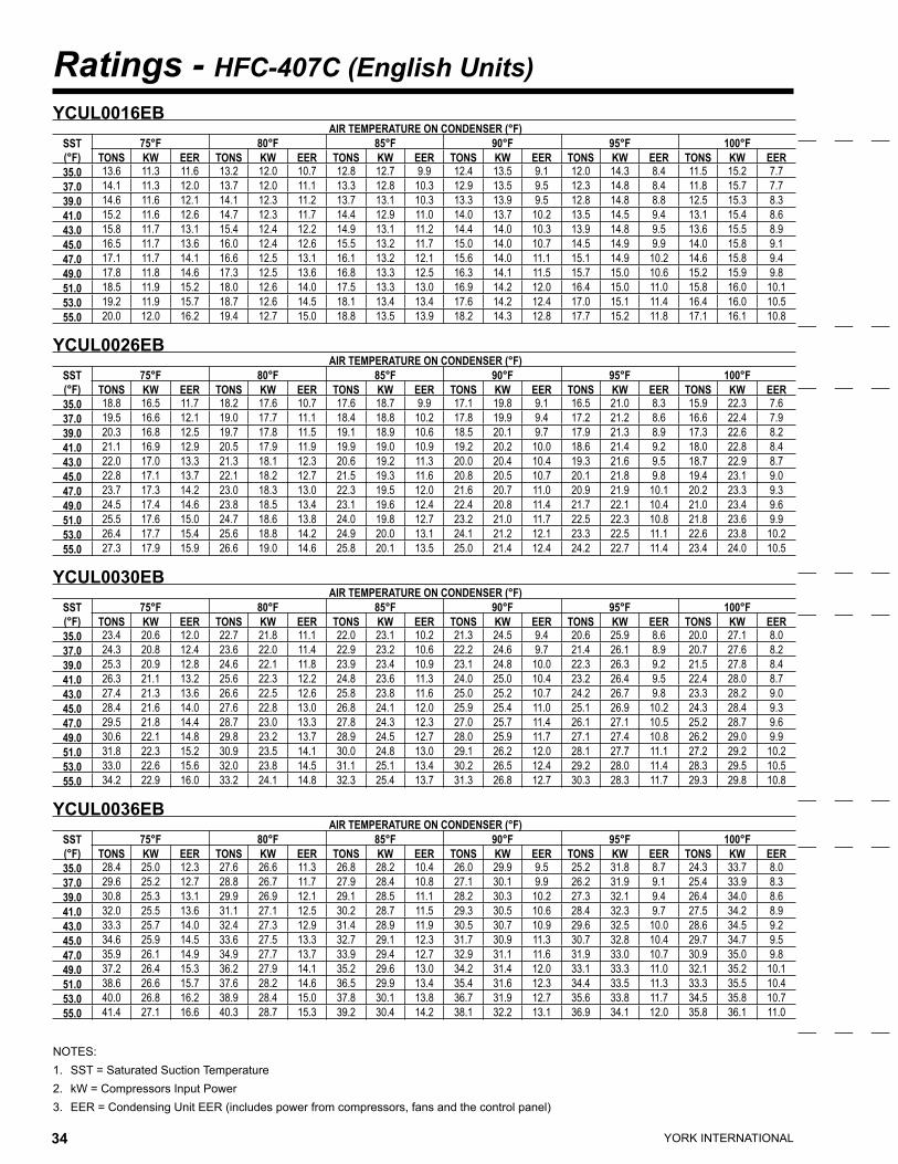
YORK INTERNATIONAL34 YORK INTERNATIONAL 35
FORM 150.63-EG1
Ratings - HFC-407C (English Units)
NOTES:1. SST = Saturated Suction Temperature2. kW = Compressors Input Power3. EER = Condensing Unit EER (includes power from compressors, fans and the control panel)
YCUL0016EB AIR TEMPERATURE ON CONDENSER (°F)
SST(°F)
75°F 80°F 85°F 90°F 95°F 100°FTONS KW EER TONS KW EER TONS KW EER TONS KW EER TONS KW EER TONS KW EER
35.0 13.6 11.3 11.6 13.2 12.0 10.7 12.8 12.7 9.9 12.4 13.5 9.1 12.0 14.3 8.4 11.5 15.2 7.737.0 14.1 11.3 12.0 13.7 12.0 11.1 13.3 12.8 10.3 12.9 13.5 9.5 12.3 14.8 8.4 11.8 15.7 7.739.0 14.6 11.6 12.1 14.1 12.3 11.2 13.7 13.1 10.3 13.3 13.9 9.5 12.8 14.8 8.8 12.5 15.3 8.341.0 15.2 11.6 12.6 14.7 12.3 11.7 14.4 12.9 11.0 14.0 13.7 10.2 13.5 14.5 9.4 13.1 15.4 8.643.0 15.8 11.7 13.1 15.4 12.4 12.2 14.9 13.1 11.2 14.4 14.0 10.3 13.9 14.8 9.5 13.6 15.5 8.945.0 16.5 11.7 13.6 16.0 12.4 12.6 15.5 13.2 11.7 15.0 14.0 10.7 14.5 14.9 9.9 14.0 15.8 9.147.0 17.1 11.7 14.1 16.6 12.5 13.1 16.1 13.2 12.1 15.6 14.0 11.1 15.1 14.9 10.2 14.6 15.8 9.449.0 17.8 11.8 14.6 17.3 12.5 13.6 16.8 13.3 12.5 16.3 14.1 11.5 15.7 15.0 10.6 15.2 15.9 9.851.0 18.5 11.9 15.2 18.0 12.6 14.0 17.5 13.3 13.0 16.9 14.2 12.0 16.4 15.0 11.0 15.8 16.0 10.153.0 19.2 11.9 15.7 18.7 12.6 14.5 18.1 13.4 13.4 17.6 14.2 12.4 17.0 15.1 11.4 16.4 16.0 10.555.0 20.0 12.0 16.2 19.4 12.7 15.0 18.8 13.5 13.9 18.2 14.3 12.8 17.7 15.2 11.8 17.1 16.1 10.8
YCUL0026EB AIR TEMPERATURE ON CONDENSER (°F)
SST(°F)
75°F 80°F 85°F 90°F 95°F 100°FTONS KW EER TONS KW EER TONS KW EER TONS KW EER TONS KW EER TONS KW EER
35.0 18.8 16.5 11.7 18.2 17.6 10.7 17.6 18.7 9.9 17.1 19.8 9.1 16.5 21.0 8.3 15.9 22.3 7.637.0 19.5 16.6 12.1 19.0 17.7 11.1 18.4 18.8 10.2 17.8 19.9 9.4 17.2 21.2 8.6 16.6 22.4 7.939.0 20.3 16.8 12.5 19.7 17.8 11.5 19.1 18.9 10.6 18.5 20.1 9.7 17.9 21.3 8.9 17.3 22.6 8.241.0 21.1 16.9 12.9 20.5 17.9 11.9 19.9 19.0 10.9 19.2 20.2 10.0 18.6 21.4 9.2 18.0 22.8 8.443.0 22.0 17.0 13.3 21.3 18.1 12.3 20.6 19.2 11.3 20.0 20.4 10.4 19.3 21.6 9.5 18.7 22.9 8.745.0 22.8 17.1 13.7 22.1 18.2 12.7 21.5 19.3 11.6 20.8 20.5 10.7 20.1 21.8 9.8 19.4 23.1 9.047.0 23.7 17.3 14.2 23.0 18.3 13.0 22.3 19.5 12.0 21.6 20.7 11.0 20.9 21.9 10.1 20.2 23.3 9.349.0 24.5 17.4 14.6 23.8 18.5 13.4 23.1 19.6 12.4 22.4 20.8 11.4 21.7 22.1 10.4 21.0 23.4 9.651.0 25.5 17.6 15.0 24.7 18.6 13.8 24.0 19.8 12.7 23.2 21.0 11.7 22.5 22.3 10.8 21.8 23.6 9.953.0 26.4 17.7 15.4 25.6 18.8 14.2 24.9 20.0 13.1 24.1 21.2 12.1 23.3 22.5 11.1 22.6 23.8 10.255.0 27.3 17.9 15.9 26.6 19.0 14.6 25.8 20.1 13.5 25.0 21.4 12.4 24.2 22.7 11.4 23.4 24.0 10.5
YCUL0030EB AIR TEMPERATURE ON CONDENSER (°F)
SST(°F)
75°F 80°F 85°F 90°F 95°F 100°FTONS KW EER TONS KW EER TONS KW EER TONS KW EER TONS KW EER TONS KW EER
35.0 23.4 20.6 12.0 22.7 21.8 11.1 22.0 23.1 10.2 21.3 24.5 9.4 20.6 25.9 8.6 20.0 27.1 8.037.0 24.3 20.8 12.4 23.6 22.0 11.4 22.9 23.2 10.6 22.2 24.6 9.7 21.4 26.1 8.9 20.7 27.6 8.239.0 25.3 20.9 12.8 24.6 22.1 11.8 23.9 23.4 10.9 23.1 24.8 10.0 22.3 26.3 9.2 21.5 27.8 8.441.0 26.3 21.1 13.2 25.6 22.3 12.2 24.8 23.6 11.3 24.0 25.0 10.4 23.2 26.4 9.5 22.4 28.0 8.743.0 27.4 21.3 13.6 26.6 22.5 12.6 25.8 23.8 11.6 25.0 25.2 10.7 24.2 26.7 9.8 23.3 28.2 9.045.0 28.4 21.6 14.0 27.6 22.8 13.0 26.8 24.1 12.0 25.9 25.4 11.0 25.1 26.9 10.2 24.3 28.4 9.347.0 29.5 21.8 14.4 28.7 23.0 13.3 27.8 24.3 12.3 27.0 25.7 11.4 26.1 27.1 10.5 25.2 28.7 9.649.0 30.6 22.1 14.8 29.8 23.2 13.7 28.9 24.5 12.7 28.0 25.9 11.7 27.1 27.4 10.8 26.2 29.0 9.951.0 31.8 22.3 15.2 30.9 23.5 14.1 30.0 24.8 13.0 29.1 26.2 12.0 28.1 27.7 11.1 27.2 29.2 10.253.0 33.0 22.6 15.6 32.0 23.8 14.5 31.1 25.1 13.4 30.2 26.5 12.4 29.2 28.0 11.4 28.3 29.5 10.555.0 34.2 22.9 16.0 33.2 24.1 14.8 32.3 25.4 13.7 31.3 26.8 12.7 30.3 28.3 11.7 29.3 29.8 10.8
YCUL0036EB AIR TEMPERATURE ON CONDENSER (°F)
SST(°F)
75°F 80°F 85°F 90°F 95°F 100°FTONS KW EER TONS KW EER TONS KW EER TONS KW EER TONS KW EER TONS KW EER
35.0 28.4 25.0 12.3 27.6 26.6 11.3 26.8 28.2 10.4 26.0 29.9 9.5 25.2 31.8 8.7 24.3 33.7 8.037.0 29.6 25.2 12.7 28.8 26.7 11.7 27.9 28.4 10.8 27.1 30.1 9.9 26.2 31.9 9.1 25.4 33.9 8.339.0 30.8 25.3 13.1 29.9 26.9 12.1 29.1 28.5 11.1 28.2 30.3 10.2 27.3 32.1 9.4 26.4 34.0 8.641.0 32.0 25.5 13.6 31.1 27.1 12.5 30.2 28.7 11.5 29.3 30.5 10.6 28.4 32.3 9.7 27.5 34.2 8.943.0 33.3 25.7 14.0 32.4 27.3 12.9 31.4 28.9 11.9 30.5 30.7 10.9 29.6 32.5 10.0 28.6 34.5 9.245.0 34.6 25.9 14.5 33.6 27.5 13.3 32.7 29.1 12.3 31.7 30.9 11.3 30.7 32.8 10.4 29.7 34.7 9.547.0 35.9 26.1 14.9 34.9 27.7 13.7 33.9 29.4 12.7 32.9 31.1 11.6 31.9 33.0 10.7 30.9 35.0 9.849.0 37.2 26.4 15.3 36.2 27.9 14.1 35.2 29.6 13.0 34.2 31.4 12.0 33.1 33.3 11.0 32.1 35.2 10.151.0 38.6 26.6 15.7 37.6 28.2 14.6 36.5 29.9 13.4 35.4 31.6 12.3 34.4 33.5 11.3 33.3 35.5 10.453.0 40.0 26.8 16.2 38.9 28.4 15.0 37.8 30.1 13.8 36.7 31.9 12.7 35.6 33.8 11.7 34.5 35.8 10.755.0 41.4 27.1 16.6 40.3 28.7 15.3 39.2 30.4 14.2 38.1 32.2 13.1 36.9 34.1 12.0 35.8 36.1 11.0
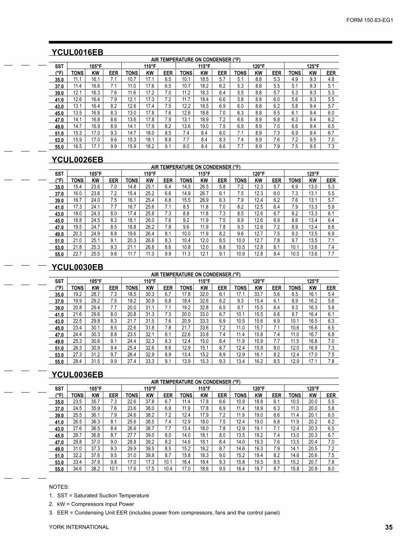
YORK INTERNATIONAL34 YORK INTERNATIONAL 35
FORM 150.63-EG1
NOTES:1. SST = Saturated Suction Temperature2. kW = Compressors Input Power3. EER = Condensing Unit EER (includes power from compressors, fans and the control panel)
YCUL0016EB AIR TEMPERATURE ON CONDENSER (°F)
SST(°F)
105°F 110°F 115°F 120°F 125°FTONS KW EER TONS KW EER TONS KW EER TONS KW EER TONS KW EER
35.0 11.1 16.1 7.1 10.7 17.1 6.5 10.1 18.5 5.7 5.1 8.8 5.3 4.9 9.3 4.837.0 11.4 16.6 7.1 11.0 17.6 6.5 10.7 18.2 6.2 5.3 8.8 5.5 5.1 9.3 5.139.0 12.1 16.3 7.6 11.6 17.2 7.0 11.2 18.3 6.4 5.5 8.8 5.7 5.3 9.3 5.341.0 12.6 16.4 7.9 12.1 17.3 7.2 11.7 18.4 6.6 5.8 8.8 6.0 5.6 9.3 5.543.0 13.1 16.4 8.2 12.6 17.4 7.5 12.2 18.5 6.9 6.0 8.8 6.2 5.8 9.4 5.745.0 13.5 16.8 8.3 13.0 17.8 7.6 12.6 18.8 7.0 6.3 8.8 6.5 6.1 9.4 6.047.0 14.1 16.8 8.6 13.6 17.8 7.9 13.1 18.9 7.2 6.6 8.9 6.8 6.3 9.4 6.249.0 14.7 16.9 8.9 14.1 17.9 8.2 13.6 19.0 7.5 6.9 8.9 7.0 6.6 9.4 6.551.0 15.3 17.0 9.3 14.7 18.0 8.5 7.4 8.4 8.0 7.1 8.9 7.3 6.9 9.4 6.753.0 15.9 17.0 9.6 15.3 18.1 8.8 7.7 8.4 8.3 7.4 8.9 7.6 7.2 9.5 7.055.0 16.5 17.1 9.9 15.9 18.2 9.1 8.0 8.4 8.6 7.7 8.9 7.9 7.5 9.5 7.3
YCUL0026EB AIR TEMPERATURE ON CONDENSER (°F)
SST(°F)
105°F 110°F 115°F 120°F 125°FTONS KW EER TONS KW EER TONS KW EER TONS KW EER TONS KW EER
35.0 15.4 23.6 7.0 14.8 25.1 6.4 14.3 26.5 5.8 7.2 12.3 5.7 6.9 13.0 5.337.0 16.0 23.8 7.2 15.4 25.2 6.6 14.9 26.7 6.1 7.5 12.3 6.0 7.3 13.1 5.539.0 16.7 24.0 7.5 16.1 25.4 6.8 15.5 26.9 6.3 7.9 12.4 6.2 7.6 13.1 5.741.0 17.3 24.1 7.7 16.7 25.6 7.1 8.5 11.8 7.0 8.2 12.5 6.4 7.9 13.3 5.943.0 18.0 24.3 8.0 17.4 25.8 7.3 8.8 11.8 7.3 8.5 12.6 6.7 8.2 13.3 6.145.0 18.8 24.5 8.3 18.1 26.0 7.6 9.2 11.9 7.5 8.9 12.6 6.9 8.6 13.4 6.447.0 19.5 24.7 8.5 18.8 26.2 7.8 9.6 11.9 7.8 9.3 12.6 7.2 8.9 13.4 6.649.0 20.3 24.9 8.8 19.6 26.4 8.1 10.0 11.9 8.2 9.6 12.7 7.5 9.3 13.5 6.951.0 21.0 25.1 9.1 20.3 26.6 8.3 10.4 12.0 8.5 10.0 12.7 7.8 9.7 13.5 7.153.0 21.8 25.3 9.3 21.1 26.8 8.6 10.8 12.0 8.8 10.5 12.8 8.1 10.1 13.6 7.455.0 22.7 25.5 9.6 11.7 11.3 9.9 11.3 12.1 9.1 10.9 12.8 8.4 10.5 13.6 7.7
YCUL0030EB AIR TEMPERATURE ON CONDENSER (°F)
SST(°F)
105°F 110°F 115°F 120°F 125°FTONS KW EER TONS KW EER TONS KW EER TONS KW EER TONS KW EER
35.0 19.2 28.7 7.3 18.5 30.3 6.7 17.8 32.0 6.1 17.1 33.7 5.6 8.5 16.1 5.437.0 19.9 29.2 7.5 19.2 30.9 6.8 18.4 32.6 6.2 9.3 15.4 6.1 8.9 16.2 5.639.0 20.8 29.4 7.7 20.0 31.1 7.1 19.2 32.8 6.5 9.7 15.5 6.4 9.3 16.3 5.841.0 21.6 29.6 8.0 20.8 31.3 7.3 20.0 33.0 6.7 10.1 15.5 6.6 9.7 16.4 6.143.0 22.5 29.8 8.3 21.7 31.5 7.6 20.9 33.3 6.9 10.5 15.6 6.9 10.1 16.5 6.345.0 23.4 30.1 8.5 22.6 31.8 7.8 21.7 33.6 7.2 11.0 15.7 7.1 10.6 16.6 6.547.0 24.4 30.3 8.8 23.5 32.1 8.1 22.6 33.8 7.4 11.4 15.8 7.4 11.0 16.7 6.849.0 25.3 30.6 9.1 24.4 32.3 8.3 12.4 15.0 8.4 11.9 15.9 7.7 11.5 16.8 7.051.0 26.3 30.9 9.4 25.4 32.6 8.6 12.9 15.1 8.7 12.4 15.9 8.0 12.0 16.9 7.353.0 27.3 31.2 9.7 26.4 32.9 8.9 13.4 15.2 8.9 12.9 16.1 8.2 12.4 17.0 7.555.0 28.4 31.5 9.9 27.4 33.3 9.1 13.9 15.3 9.3 13.4 16.2 8.5 12.9 17.1 7.8
YCUL0036EB AIR TEMPERATURE ON CONDENSER (°F)
SST(°F)
105°F 110°F 115°F 120°F 125°FTONS KW EER TONS KW EER TONS KW EER TONS KW EER TONS KW EER
35.0 23.5 35.7 7.3 22.6 37.8 6.7 11.4 17.8 6.6 10.9 18.8 6.1 10.5 20.0 5.537.0 24.5 35.9 7.6 23.6 38.0 6.9 11.9 17.8 6.9 11.4 18.9 6.3 11.0 20.0 5.839.0 25.5 36.1 7.9 24.6 38.2 7.2 12.4 17.9 7.2 11.9 19.0 6.6 11.4 20.1 6.041.0 26.5 36.3 8.1 25.6 38.5 7.4 12.9 18.0 7.5 12.4 19.0 6.8 11.9 20.2 6.243.0 27.6 36.5 8.4 26.6 38.7 7.7 13.4 18.0 7.8 12.9 19.1 7.1 12.4 20.3 6.545.0 28.7 36.8 8.7 27.7 39.0 8.0 14.0 18.1 8.0 13.5 19.2 7.4 13.0 20.3 6.747.0 29.8 37.0 9.0 28.8 39.2 8.2 14.6 18.1 8.4 14.0 19.3 7.6 13.5 20.4 7.049.0 31.0 37.3 9.3 29.9 39.5 8.5 15.2 18.2 8.7 14.6 19.3 7.9 14.1 20.5 7.251.0 32.2 37.6 9.5 31.0 39.8 8.7 15.8 18.3 9.0 15.2 19.4 8.2 14.6 20.6 7.553.0 33.4 37.9 9.8 17.0 17.3 10.1 16.4 18.4 9.3 15.8 19.5 8.5 15.2 20.7 7.855.0 34.6 38.2 10.1 17.6 17.5 10.4 17.0 18.6 9.5 16.4 19.7 8.7 15.8 20.9 8.0
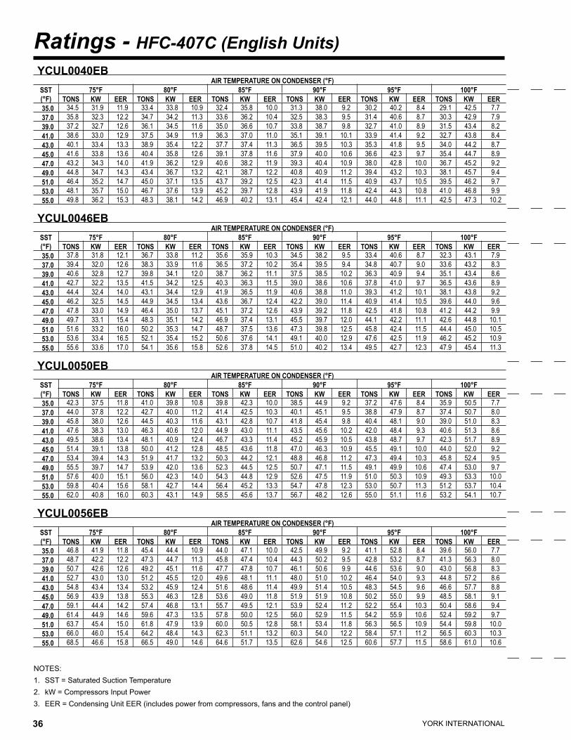
YORK INTERNATIONAL36 YORK INTERNATIONAL 37
FORM 150.63-EG1
Ratings - HFC-407C (English Units)
NOTES:1. SST = Saturated Suction Temperature2. kW = Compressors Input Power3. EER = Condensing Unit EER (includes power from compressors, fans and the control panel)
YCUL0040EB AIR TEMPERATURE ON CONDENSER (°F)
SST(°F)
75°F 80°F 85°F 90°F 95°F 100°FTONS KW EER TONS KW EER TONS KW EER TONS KW EER TONS KW EER TONS KW EER
35.0 34.5 31.9 11.9 33.4 33.8 10.9 32.4 35.8 10.0 31.3 38.0 9.2 30.2 40.2 8.4 29.1 42.5 7.737.0 35.8 32.3 12.2 34.7 34.2 11.3 33.6 36.2 10.4 32.5 38.3 9.5 31.4 40.6 8.7 30.3 42.9 7.939.0 37.2 32.7 12.6 36.1 34.5 11.6 35.0 36.6 10.7 33.8 38.7 9.8 32.7 41.0 8.9 31.5 43.4 8.241.0 38.6 33.0 12.9 37.5 34.9 11.9 36.3 37.0 11.0 35.1 39.1 10.1 33.9 41.4 9.2 32.7 43.8 8.443.0 40.1 33.4 13.3 38.9 35.4 12.2 37.7 37.4 11.3 36.5 39.5 10.3 35.3 41.8 9.5 34.0 44.2 8.745.0 41.6 33.8 13.6 40.4 35.8 12.6 39.1 37.8 11.6 37.9 40.0 10.6 36.6 42.3 9.7 35.4 44.7 8.947.0 43.2 34.3 14.0 41.9 36.2 12.9 40.6 38.2 11.9 39.3 40.4 10.9 38.0 42.8 10.0 36.7 45.2 9.249.0 44.8 34.7 14.3 43.4 36.7 13.2 42.1 38.7 12.2 40.8 40.9 11.2 39.4 43.2 10.3 38.1 45.7 9.451.0 46.4 35.2 14.7 45.0 37.1 13.5 43.7 39.2 12.5 42.3 41.4 11.5 40.9 43.7 10.5 39.5 46.2 9.753.0 48.1 35.7 15.0 46.7 37.6 13.9 45.2 39.7 12.8 43.9 41.9 11.8 42.4 44.3 10.8 41.0 46.8 9.955.0 49.8 36.2 15.3 48.3 38.1 14.2 46.9 40.2 13.1 45.4 42.4 12.1 44.0 44.8 11.1 42.5 47.3 10.2
YCUL0046EB AIR TEMPERATURE ON CONDENSER (°F)
SST(°F)
75°F 80°F 85°F 90°F 95°F 100°FTONS KW EER TONS KW EER TONS KW EER TONS KW EER TONS KW EER TONS KW EER
35.0 37.8 31.8 12.1 36.7 33.8 11.2 35.6 35.9 10.3 34.5 38.2 9.5 33.4 40.6 8.7 32.3 43.1 7.937.0 39.4 32.0 12.6 38.3 33.9 11.6 36.5 37.2 10.2 35.4 39.5 9.4 34.8 40.7 9.0 33.6 43.2 8.339.0 40.6 32.8 12.7 39.8 34.1 12.0 38.7 36.2 11.1 37.5 38.5 10.2 36.3 40.9 9.4 35.1 43.4 8.641.0 42.7 32.2 13.5 41.5 34.2 12.5 40.3 36.3 11.5 39.0 38.6 10.6 37.8 41.0 9.7 36.5 43.6 8.943.0 44.4 32.4 14.0 43.1 34.4 12.9 41.9 36.5 11.9 40.6 38.8 11.0 39.3 41.2 10.1 38.1 43.8 9.245.0 46.2 32.5 14.5 44.9 34.5 13.4 43.6 36.7 12.4 42.2 39.0 11.4 40.9 41.4 10.5 39.6 44.0 9.647.0 47.8 33.0 14.9 46.4 35.0 13.7 45.1 37.2 12.6 43.9 39.2 11.8 42.5 41.8 10.8 41.2 44.2 9.949.0 49.7 33.1 15.4 48.3 35.1 14.2 46.9 37.4 13.1 45.5 39.7 12.0 44.1 42.2 11.1 42.6 44.8 10.151.0 51.6 33.2 16.0 50.2 35.3 14.7 48.7 37.5 13.6 47.3 39.8 12.5 45.8 42.4 11.5 44.4 45.0 10.553.0 53.6 33.4 16.5 52.1 35.4 15.2 50.6 37.6 14.1 49.1 40.0 12.9 47.6 42.5 11.9 46.2 45.2 10.955.0 55.6 33.6 17.0 54.1 35.6 15.8 52.6 37.8 14.5 51.0 40.2 13.4 49.5 42.7 12.3 47.9 45.4 11.3
YCUL0050EB AIR TEMPERATURE ON CONDENSER (°F)
SST(°F)
75°F 80°F 85°F 90°F 95°F 100°FTONS KW EER TONS KW EER TONS KW EER TONS KW EER TONS KW EER TONS KW EER
35.0 42.3 37.5 11.8 41.0 39.8 10.8 39.8 42.3 10.0 38.5 44.9 9.2 37.2 47.6 8.4 35.9 50.5 7.737.0 44.0 37.8 12.2 42.7 40.0 11.2 41.4 42.5 10.3 40.1 45.1 9.5 38.8 47.9 8.7 37.4 50.7 8.039.0 45.8 38.0 12.6 44.5 40.3 11.6 43.1 42.8 10.7 41.8 45.4 9.8 40.4 48.1 9.0 39.0 51.0 8.341.0 47.6 38.3 13.0 46.3 40.6 12.0 44.9 43.0 11.1 43.5 45.6 10.2 42.0 48.4 9.3 40.6 51.3 8.643.0 49.5 38.6 13.4 48.1 40.9 12.4 46.7 43.3 11.4 45.2 45.9 10.5 43.8 48.7 9.7 42.3 51.7 8.945.0 51.4 39.1 13.8 50.0 41.2 12.8 48.5 43.6 11.8 47.0 46.3 10.9 45.5 49.1 10.0 44.0 52.0 9.247.0 53.4 39.4 14.3 51.9 41.7 13.2 50.3 44.2 12.1 48.8 46.8 11.2 47.3 49.4 10.3 45.8 52.4 9.549.0 55.5 39.7 14.7 53.9 42.0 13.6 52.3 44.5 12.5 50.7 47.1 11.5 49.1 49.9 10.6 47.4 53.0 9.751.0 57.6 40.0 15.1 56.0 42.3 14.0 54.3 44.8 12.9 52.6 47.5 11.9 51.0 50.3 10.9 49.3 53.3 10.053.0 59.8 40.4 15.6 58.1 42.7 14.4 56.4 45.2 13.3 54.7 47.8 12.3 53.0 50.7 11.3 51.2 53.7 10.455.0 62.0 40.8 16.0 60.3 43.1 14.9 58.5 45.6 13.7 56.7 48.2 12.6 55.0 51.1 11.6 53.2 54.1 10.7
YCUL0056EB AIR TEMPERATURE ON CONDENSER (°F)
SST(°F)
75°F 80°F 85°F 90°F 95°F 100°FTONS KW EER TONS KW EER TONS KW EER TONS KW EER TONS KW EER TONS KW EER
35.0 46.8 41.9 11.8 45.4 44.4 10.9 44.0 47.1 10.0 42.5 49.9 9.2 41.1 52.8 8.4 39.6 56.0 7.737.0 48.7 42.2 12.2 47.3 44.7 11.3 45.8 47.4 10.4 44.3 50.2 9.5 42.8 53.2 8.7 41.3 56.3 8.039.0 50.7 42.6 12.6 49.2 45.1 11.6 47.7 47.8 10.7 46.1 50.6 9.9 44.6 53.6 9.0 43.0 56.8 8.341.0 52.7 43.0 13.0 51.2 45.5 12.0 49.6 48.1 11.1 48.0 51.0 10.2 46.4 54.0 9.3 44.8 57.2 8.643.0 54.8 43.4 13.4 53.2 45.9 12.4 51.6 48.6 11.4 49.9 51.4 10.5 48.3 54.5 9.6 46.6 57.7 8.845.0 56.9 43.9 13.8 55.3 46.3 12.8 53.6 49.0 11.8 51.9 51.9 10.8 50.2 55.0 9.9 48.5 58.1 9.147.0 59.1 44.4 14.2 57.4 46.8 13.1 55.7 49.5 12.1 53.9 52.4 11.2 52.2 55.4 10.3 50.4 58.6 9.449.0 61.4 44.9 14.6 59.6 47.3 13.5 57.8 50.0 12.5 56.0 52.9 11.5 54.2 55.9 10.6 52.4 59.2 9.751.0 63.7 45.4 15.0 61.8 47.9 13.9 60.0 50.5 12.8 58.1 53.4 11.8 56.3 56.5 10.9 54.4 59.8 10.053.0 66.0 46.0 15.4 64.2 48.4 14.3 62.3 51.1 13.2 60.3 54.0 12.2 58.4 57.1 11.2 56.5 60.3 10.355.0 68.5 46.6 15.8 66.5 49.0 14.6 64.6 51.7 13.5 62.6 54.6 12.5 60.6 57.7 11.5 58.6 61.0 10.6

YORK INTERNATIONAL36 YORK INTERNATIONAL 37
FORM 150.63-EG1
NOTES:1. SST = Saturated Suction Temperature2. kW = Compressors Input Power3. EER = Condensing Unit EER (includes power from compressors, fans and the control panel)
YCUL0040EB AIR TEMPERATURE ON CONDENSER (°F)
SST(°F)
105°F 110°F 115°F 120°F 125°FTONS KW EER TONS KW EER TONS KW EER TONS KW EER TONS KW EER
35.0 28.0 44.9 7.0 26.9 47.4 6.4 25.9 49.9 5.9 17.1 32.6 5.8 16.4 34.3 5.337.0 29.2 45.4 7.3 28.0 47.8 6.6 27.0 50.4 6.1 17.9 32.8 6.0 17.2 34.5 5.539.0 30.3 45.8 7.5 29.2 48.3 6.9 28.1 50.9 6.3 18.7 33.0 6.3 17.9 34.7 5.741.0 31.6 46.3 7.7 30.4 48.8 7.1 20.3 31.5 7.1 19.5 33.2 6.5 18.7 35.0 5.943.0 32.8 46.7 7.9 31.6 49.3 7.3 21.1 31.7 7.4 20.3 33.5 6.7 19.5 35.2 6.245.0 34.1 47.2 8.2 32.9 49.8 7.5 22.0 31.9 7.6 21.2 33.7 7.0 20.4 35.5 6.447.0 35.4 47.7 8.4 34.1 50.3 7.7 22.9 32.2 7.9 22.1 33.9 7.2 21.2 35.8 6.649.0 36.8 48.3 8.6 35.5 50.9 7.9 23.9 32.4 8.1 23.0 34.2 7.5 22.1 36.1 6.851.0 38.2 48.8 8.9 25.8 30.9 9.2 24.8 32.7 8.4 23.9 34.5 7.7 23.0 36.4 7.153.0 39.6 49.4 9.1 26.8 31.1 9.5 25.8 32.9 8.7 24.9 34.8 8.0 24.0 36.6 7.355.0 41.1 50.0 9.3 27.8 31.4 9.8 26.8 33.2 9.0 25.9 35.0 8.2 24.9 37.0 7.5
YCUL0046EB AIR TEMPERATURE ON CONDENSER (°F)
SST(°F)
105°F 110°F 115°F 120°F 125°FTONS KW EER TONS KW EER TONS KW EER TONS KW EER TONS KW EER
35.0 30.5 47.3 6.9 29.4 50.2 6.3 29.0 51.4 6.1 14.2 25.0 5.6 13.7 26.5 5.137.0 32.5 45.9 7.6 31.3 48.7 6.9 30.2 51.7 6.3 14.9 25.1 5.8 14.3 26.6 5.339.0 33.9 46.1 7.9 32.7 48.9 7.2 31.5 51.9 6.6 15.5 25.1 6.1 14.9 26.6 5.641.0 35.3 46.3 8.2 34.1 49.1 7.5 32.9 52.1 6.8 16.2 25.1 6.3 15.6 26.7 5.843.0 36.8 46.5 8.5 35.5 49.3 7.8 34.3 52.3 7.1 16.9 25.2 6.6 16.3 26.7 6.145.0 38.3 46.7 8.8 37.0 49.6 8.0 35.7 52.6 7.4 17.7 25.2 6.9 17.0 26.7 6.347.0 39.8 46.9 9.1 38.5 49.8 8.3 37.2 52.8 7.6 18.4 25.2 7.2 17.7 26.8 6.649.0 41.5 47.1 9.4 40.1 50.0 8.6 38.7 53.1 7.9 19.2 25.3 7.5 18.5 26.8 6.951.0 42.9 47.8 9.6 41.4 50.8 8.8 40.0 53.9 8.1 20.0 25.3 7.8 19.3 26.9 7.153.0 44.6 47.9 10.0 43.1 50.9 9.2 21.6 23.8 8.8 20.9 25.3 8.1 20.1 26.9 7.455.0 46.4 48.2 10.4 44.9 51.1 9.5 22.5 23.9 9.2 21.7 25.4 8.4 20.9 27.0 7.7
YCUL0050EB AIR TEMPERATURE ON CONDENSER (°F)
SST(°F)
105°F 110°F 115°F 120°F 125°FTONS KW EER TONS KW EER TONS KW EER TONS KW EER TONS KW EER
35.0 34.6 53.5 7.0 33.3 56.6 6.4 32.2 59.5 5.9 15.9 28.6 5.6 15.3 30.3 5.137.0 36.1 53.7 7.3 34.8 56.9 6.7 33.5 60.2 6.1 16.7 28.7 5.8 16.0 30.4 5.339.0 37.6 54.0 7.6 36.3 57.2 6.9 34.9 60.5 6.3 17.4 28.8 6.1 16.7 30.5 5.641.0 39.2 54.4 7.8 37.8 57.6 7.2 27.0 42.0 6.8 18.2 28.9 6.3 17.5 30.6 5.843.0 40.8 54.7 8.1 39.4 57.9 7.4 19.7 27.4 7.2 19.0 29.0 6.6 18.2 30.8 6.045.0 42.5 55.1 8.4 41.0 58.4 7.7 20.5 27.5 7.4 19.8 29.1 6.8 19.0 30.9 6.347.0 44.2 55.5 8.7 42.6 58.8 7.9 21.4 27.6 7.7 20.6 29.3 7.1 19.8 31.0 6.549.0 45.8 56.1 8.9 44.2 59.5 8.2 22.3 27.7 8.0 21.5 29.4 7.4 20.7 31.1 6.851.0 47.7 56.5 9.2 46.0 59.8 8.4 23.2 27.8 8.4 22.4 29.5 7.7 21.6 31.2 7.053.0 49.5 56.9 9.5 47.8 60.3 8.7 24.2 28.0 8.6 23.3 29.7 7.9 22.4 31.4 7.355.0 51.5 57.4 9.8 36.9 41.3 9.5 25.2 28.1 9.0 24.3 29.8 8.2 23.4 31.6 7.5
YCUL0056EB AIR TEMPERATURE ON CONDENSER (°F)
SST(°F)
105°F 110°F 115°F 120°F 125°FTONS KW EER TONS KW EER TONS KW EER TONS KW EER TONS KW EER
35.0 38.2 59.2 7.1 36.7 62.6 6.5 35.5 65.3 6.0 17.7 31.2 5.8 17.0 33.0 5.337.0 39.8 59.6 7.3 38.3 63.0 6.7 36.8 66.4 6.1 18.5 31.4 6.0 17.7 33.1 5.539.0 41.5 60.0 7.6 39.9 63.4 6.9 38.4 66.9 6.4 19.3 31.5 6.2 18.5 33.3 5.741.0 43.2 60.5 7.8 41.6 63.9 7.2 40.0 67.4 6.6 20.2 31.7 6.5 19.4 33.5 5.943.0 45.0 61.0 8.1 43.3 64.4 7.4 41.7 68.0 6.8 21.0 31.9 6.7 20.2 33.7 6.245.0 46.8 61.5 8.4 45.1 65.0 7.7 22.8 30.3 7.6 21.9 32.0 7.0 21.1 33.9 6.447.0 48.6 62.0 8.6 46.9 65.6 7.9 23.8 30.4 7.9 22.9 32.2 7.3 22.0 34.1 6.649.0 50.6 62.6 8.9 48.8 66.1 8.2 24.7 30.6 8.2 23.8 32.4 7.5 22.9 34.3 6.951.0 52.5 63.2 9.2 50.7 66.8 8.4 25.8 30.8 8.5 24.8 32.6 7.8 23.9 34.5 7.253.0 54.6 63.8 9.4 52.7 67.4 8.7 26.8 31.1 8.8 25.8 32.9 8.0 24.8 34.8 7.455.0 56.7 64.4 9.7 28.9 29.5 9.9 27.9 31.2 9.1 26.9 33.1 8.3 25.8 35.0 7.6

YORK INTERNATIONAL38 YORK INTERNATIONAL 39
FORM 150.63-EG1
Ratings - HFC-407C (English Units)
NOTES:1. SST = Saturated Suction Temperature2. kW = Compressors Input Power3. EER = Condensing Unit EER (includes power from compressors, fans and the control panel)
YCUL0060EB AIR TEMPERATURE ON CONDENSER (°F)
SST(°F)
75°F 80°F 85°F 90°F 95°F 100°FTONS KW EER TONS KW EER TONS KW EER TONS KW EER TONS KW EER TONS KW EER
35.0 51.2 47.6 11.6 49.8 50.5 10.6 48.3 53.5 9.8 46.7 56.7 9.0 45.2 60.1 8.3 43.6 63.6 7.637.0 53.3 48.0 11.9 51.8 50.9 11.0 50.2 53.9 10.1 48.6 57.2 9.3 47.1 60.6 8.6 45.4 64.1 7.839.0 55.4 48.5 12.3 53.8 51.3 11.3 52.2 54.4 10.4 50.6 57.6 9.6 48.9 61.0 8.8 47.3 64.6 8.141.0 57.6 48.9 12.7 56.0 51.8 11.7 54.3 54.9 10.8 52.6 58.1 9.9 50.9 61.6 9.1 49.1 65.2 8.343.0 59.8 49.4 13.0 58.1 52.3 12.0 56.4 55.4 11.1 54.7 58.6 10.2 52.9 62.1 9.4 51.1 65.8 8.645.0 62.1 50.0 13.4 60.3 52.8 12.4 58.6 55.9 11.4 56.8 59.2 10.5 54.9 62.7 9.6 53.1 66.3 8.947.0 64.4 50.5 13.8 62.6 53.4 12.7 60.8 56.5 11.7 58.9 59.8 10.8 57.0 63.3 9.9 55.1 67.0 9.149.0 66.8 51.1 14.2 64.9 54.0 13.1 63.0 57.1 12.1 61.1 60.4 11.1 59.2 63.9 10.2 57.2 67.6 9.451.0 69.3 51.7 14.5 67.3 54.6 13.4 65.4 57.7 12.4 63.4 61.0 11.4 61.4 64.5 10.5 59.3 68.3 9.653.0 71.8 52.3 14.9 69.8 55.2 13.8 67.7 58.3 12.7 65.7 61.7 11.7 63.6 65.2 10.8 61.5 69.0 9.955.0 74.3 52.9 15.2 72.3 55.8 14.1 70.2 59.0 13.0 68.1 62.3 12.0 65.9 65.9 11.1 63.8 69.7 10.2
YCUL0066EB AIR TEMPERATURE ON CONDENSER (°F)
SST(°F)
75°F 80°F 85°F 90°F 95°F 100°FTONS KW EER TONS KW EER TONS KW EER TONS KW EER TONS KW EER TONS KW EER
35.0 56.8 49.7 12.3 55.2 52.7 11.4 53.6 55.9 10.5 52.0 59.3 9.6 50.4 62.9 8.8 48.9 66.1 8.237.0 59.1 50.0 12.8 57.5 53.0 11.8 55.8 56.3 10.8 54.2 59.6 10.0 52.5 63.2 9.1 50.8 67.0 8.439.0 61.5 50.3 13.2 59.8 53.4 12.2 58.1 56.6 11.2 56.4 60.0 10.3 54.6 63.6 9.5 52.8 67.4 8.741.0 63.9 50.7 13.6 62.2 53.8 12.6 60.4 57.0 11.6 58.6 60.5 10.6 56.8 64.1 9.8 54.9 67.9 9.043.0 66.4 51.1 14.0 64.6 54.2 13.0 62.8 57.5 11.9 60.9 60.9 11.0 59.0 64.6 10.1 57.1 68.4 9.345.0 68.9 51.6 14.5 67.1 54.7 13.4 65.2 58.0 12.3 63.3 61.4 11.3 61.3 65.1 10.4 59.4 68.9 9.647.0 71.5 52.1 14.9 69.6 55.2 13.7 67.7 58.5 12.7 65.7 61.9 11.7 63.7 65.6 10.7 61.6 69.5 9.849.0 74.2 52.6 15.3 72.2 55.7 14.1 70.2 59.0 13.0 68.1 62.5 12.0 66.1 66.2 11.0 64.0 70.1 10.151.0 76.9 53.1 15.7 74.8 56.2 14.5 72.8 59.5 13.4 70.6 63.1 12.3 68.5 66.8 11.4 66.3 70.7 10.453.0 79.6 53.6 16.1 77.5 56.8 14.9 75.4 60.1 13.8 73.2 63.7 12.7 71.0 67.4 11.7 68.8 71.4 10.755.0 82.5 54.2 16.6 80.3 57.4 15.3 78.1 60.7 14.1 75.8 64.3 13.0 73.6 68.0 12.0 71.3 72.0 11.0
YCUL0076EB AIR TEMPERATURE ON CONDENSER (°F)
SST(°F)
75°F 80°F 85°F 90°F 95°F 100°FTONS KW EER TONS KW EER TONS KW EER TONS KW EER TONS KW EER TONS KW EER
35.0 62.4 58.2 11.5 60.5 61.8 10.6 58.6 65.5 9.7 56.6 69.5 8.9 54.7 73.6 8.2 52.7 78.0 7.537.0 64.9 58.7 11.9 63.0 62.2 10.9 61.0 66.0 10.0 58.9 70.0 9.2 57.0 74.2 8.4 54.9 78.6 7.739.0 67.5 59.2 12.3 65.5 62.7 11.3 63.4 66.6 10.4 61.3 70.6 9.5 59.2 74.8 8.7 57.2 79.2 8.041.0 70.1 59.7 12.6 68.0 63.3 11.6 65.9 67.1 10.7 63.8 71.2 9.8 61.6 75.4 9.0 59.5 80.0 8.243.0 72.8 60.3 13.0 70.7 63.9 12.0 68.5 67.7 11.0 66.3 71.8 10.1 64.0 76.1 9.3 61.8 80.6 8.545.0 75.6 60.9 13.4 73.4 64.5 12.3 71.1 68.4 11.4 68.8 72.4 10.4 66.5 76.8 9.6 64.3 81.3 8.847.0 78.5 61.5 13.8 76.1 65.2 12.7 73.8 69.0 11.7 71.5 73.2 10.7 69.1 77.5 9.8 66.8 82.1 9.049.0 81.4 62.2 14.2 79.0 65.8 13.1 76.6 69.7 12.0 74.2 73.9 11.0 71.8 78.2 10.1 69.3 82.8 9.351.0 84.4 62.9 14.5 81.9 66.5 13.4 79.4 70.5 12.3 76.9 74.6 11.3 74.4 79.0 10.4 72.0 83.6 9.553.0 87.5 63.6 14.9 84.9 67.3 13.8 82.4 71.2 12.7 79.8 75.4 11.6 77.2 79.9 10.7 74.7 84.5 9.855.0 90.6 64.3 15.3 88.0 68.0 14.1 85.3 72.0 13.0 82.7 76.2 12.0 80.1 80.7 11.0 77.4 85.4 10.1
YCUL0080EB AIR TEMPERATURE ON CONDENSER (°F)
SST(°F)
75°F 80°F 85°F 90°F 95°F 100°FTONS KW EER TONS KW EER TONS KW EER TONS KW EER TONS KW EER TONS KW EER
35.0 70.1 63.6 11.9 68.0 67.5 11.0 65.8 71.6 10.1 63.7 75.9 9.2 61.4 80.6 8.4 59.2 85.3 7.737.0 72.9 64.2 12.3 70.7 68.1 11.3 68.5 72.2 10.4 66.3 76.5 9.5 64.0 81.1 8.7 61.7 86.0 8.039.0 75.8 64.8 12.7 73.6 68.6 11.7 71.3 72.8 10.8 68.9 77.2 9.9 66.6 81.8 9.0 64.2 86.7 8.241.0 78.8 65.5 13.1 76.5 69.3 12.1 74.1 73.4 11.1 71.7 77.8 10.2 69.3 82.5 9.3 66.8 87.4 8.543.0 81.9 66.1 13.5 79.5 70.0 12.4 77.0 74.1 11.4 74.5 78.5 10.5 72.0 83.2 9.6 69.5 88.1 8.845.0 85.1 66.9 13.9 82.6 70.7 12.8 80.0 74.8 11.8 77.5 79.3 10.8 74.9 84.0 9.9 72.3 89.0 9.147.0 88.3 67.7 14.2 85.7 71.4 13.2 83.1 75.6 12.1 80.4 80.1 11.1 77.8 84.8 10.2 75.1 89.8 9.349.0 91.6 68.5 14.6 89.0 72.3 13.5 86.2 76.4 12.4 83.5 80.9 11.4 80.8 85.6 10.5 78.0 90.6 9.651.0 95.1 69.3 15.0 92.3 73.1 13.9 89.5 77.3 12.8 86.7 81.7 11.7 83.8 86.5 10.8 81.0 91.6 9.953.0 98.6 70.2 15.4 95.7 74.0 14.2 92.8 78.1 13.1 89.9 82.7 12.1 87.0 87.5 11.1 84.1 92.5 10.255.0 102.2 71.2 15.7 99.2 75.0 14.6 96.2 79.2 13.4 93.3 83.6 12.4 90.2 88.4 11.4 87.2 93.5 10.4
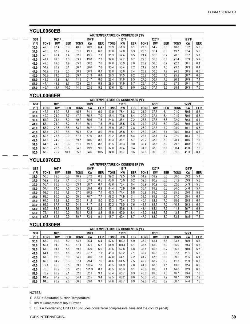
YORK INTERNATIONAL38 YORK INTERNATIONAL 39
FORM 150.63-EG1
NOTES:1. SST = Saturated Suction Temperature2. kW = Compressors Input Power3. EER = Condensing Unit EER (includes power from compressors, fans and the control panel)
YCUL0060EB AIR TEMPERATURE ON CONDENSER (°F)
SST(°F)
105°F 110°F 115°F 120°F 125°FTONS KW EER TONS KW EER TONS KW EER TONS KW EER TONS KW EER
35.0 42.0 67.4 6.9 40.6 70.9 6.4 28.9 51.3 6.1 27.8 54.2 5.6 18.8 37.2 5.337.0 43.8 67.9 7.2 31.2 49.1 6.8 30.0 52.0 6.3 20.5 35.4 6.0 19.7 37.4 5.539.0 45.6 68.4 7.4 32.5 49.5 7.1 31.3 52.4 6.5 21.4 35.6 6.2 20.5 37.7 5.741.0 47.4 69.0 7.6 33.9 49.8 7.3 32.6 52.7 6.7 22.3 35.8 6.5 21.4 37.9 5.943.0 49.3 69.6 7.9 35.3 50.2 7.6 34.0 53.0 7.0 23.2 36.0 6.7 22.3 38.1 6.145.0 51.2 70.2 8.1 36.7 50.6 7.8 35.4 53.4 7.2 24.2 36.1 7.0 23.3 38.3 6.447.0 53.2 70.9 8.3 38.2 50.9 8.1 36.8 53.8 7.4 25.2 36.3 7.2 24.2 38.5 6.649.0 55.2 71.5 8.6 39.7 51.3 8.4 27.3 34.5 8.2 26.2 36.5 7.5 25.2 38.7 6.851.0 42.8 48.9 9.4 41.3 51.7 8.6 28.4 34.6 8.5 27.3 36.7 7.8 26.3 38.9 7.153.0 44.4 49.2 9.7 42.9 52.1 8.9 29.5 34.9 8.7 28.4 37.0 8.0 27.3 39.1 7.355.0 46.1 49.7 10.0 44.5 52.5 9.2 30.6 35.1 9.0 29.5 37.1 8.3 28.4 39.3 7.6
YCUL0066EB AIR TEMPERATURE ON CONDENSER (°F)
SST(°F)
105°F 110°F 115°F 120°F 125°FTONS KW EER TONS KW EER TONS KW EER TONS KW EER TONS KW EER
35.0 47.3 69.9 7.5 45.6 74.1 6.9 43.9 78.4 6.3 21.9 37.3 6.1 21.0 39.5 5.637.0 49.0 71.0 7.7 47.2 75.2 7.0 45.4 79.6 6.4 22.9 37.4 6.4 21.9 39.6 5.839.0 51.0 71.4 8.0 49.2 75.6 7.3 24.8 35.4 7.2 23.8 37.5 6.6 22.9 39.8 6.141.0 53.1 71.9 8.2 51.2 76.1 7.5 25.8 35.5 7.5 24.9 37.7 6.9 23.9 39.9 6.343.0 55.2 72.5 8.5 53.2 76.7 7.8 26.9 35.7 7.8 25.9 37.8 7.2 24.9 40.1 6.545.0 57.4 73.0 8.8 55.3 77.3 8.0 28.0 35.8 8.1 27.0 38.0 7.4 25.9 40.3 6.847.0 59.5 73.6 9.0 57.5 77.9 8.3 29.2 35.9 8.4 28.1 38.1 7.7 27.0 40.4 7.049.0 61.8 74.2 9.3 59.7 78.6 8.5 30.3 36.1 8.7 29.2 38.3 8.0 28.1 40.6 7.351.0 64.1 74.9 9.6 61.9 79.2 8.8 31.5 36.3 9.0 30.4 38.5 8.3 29.2 40.8 7.653.0 66.5 75.5 9.8 64.2 79.9 9.0 32.8 36.4 9.4 31.6 38.6 8.6 30.4 41.0 7.855.0 68.9 76.2 10.1 35.2 34.6 10.5 34.0 36.7 9.6 32.8 39.0 8.8 31.5 41.3 8.1
YCUL0076EB AIR TEMPERATURE ON CONDENSER (°F)
SST(°F)
105°F 110°F 115°F 120°F 125°FTONS KW EER TONS KW EER TONS KW EER TONS KW EER TONS KW EER
35.0 50.8 82.5 6.8 48.9 87.2 6.2 39.2 72.5 5.9 31.2 59.9 5.6 30.0 63.2 5.137.0 52.9 83.2 7.1 51.0 87.9 6.5 40.9 73.0 6.2 32.6 60.2 5.8 31.2 63.9 5.339.0 55.1 83.8 7.3 53.1 88.7 6.7 42.6 73.4 6.4 33.9 60.9 6.0 32.6 64.3 5.541.0 57.4 84.5 7.5 55.3 89.4 6.9 44.4 73.9 6.6 35.4 61.2 6.2 34.0 64.6 5.743.0 59.6 85.3 7.8 57.5 90.2 7.1 46.3 74.4 6.8 36.9 61.5 6.5 35.5 65.0 5.945.0 62.0 86.0 8.0 50.0 70.7 7.7 48.2 74.9 7.1 38.5 61.9 6.7 37.0 65.4 6.147.0 64.5 86.8 8.3 52.0 71.2 8.0 50.2 75.4 7.3 40.1 62.3 7.0 38.6 65.8 6.449.0 66.9 87.7 8.5 54.1 71.7 8.3 52.2 76.0 7.6 41.7 62.7 7.2 40.2 66.3 6.651.0 69.5 88.5 8.8 56.2 72.3 8.5 45.1 59.6 8.1 43.4 63.1 7.5 41.8 66.7 6.853.0 72.1 89.4 9.0 58.4 72.8 8.8 46.9 60.0 8.4 45.2 63.5 7.7 43.5 67.1 7.155.0 62.8 69.3 9.9 60.7 73.4 9.1 48.7 60.4 8.7 47.0 63.9 8.0 33.5 46.5 7.5
YCUL0080EB AIR TEMPERATURE ON CONDENSER (°F)
SST(°F)
105°F 110°F 115°F 120°F 125°FTONS KW EER TONS KW EER TONS KW EER TONS KW EER TONS KW EER
35.0 57.0 90.3 7.0 54.8 95.4 6.4 52.6 100.6 5.9 35.0 65.4 5.8 33.5 68.9 5.337.0 59.4 91.0 7.3 57.1 96.1 6.7 54.9 101.4 6.1 36.5 65.9 6.0 35.0 69.4 5.539.0 61.9 91.7 7.5 59.5 96.9 6.9 39.6 62.8 6.8 38.1 66.3 6.2 36.5 70.0 5.741.0 64.4 92.5 7.8 62.0 97.7 7.1 41.3 63.2 7.1 39.7 66.8 6.5 37.8 71.1 5.843.0 67.0 93.3 8.0 64.5 98.6 7.3 42.8 64.1 7.2 41.2 67.8 6.6 39.5 71.5 6.145.0 69.6 94.2 8.3 67.1 99.4 7.6 44.6 64.5 7.5 42.9 68.2 6.9 41.3 71.9 6.347.0 72.4 95.0 8.5 69.8 100.4 7.8 46.5 64.9 7.8 44.8 68.5 7.1 43.0 72.4 6.549.0 75.3 95.9 8.8 72.6 101.3 8.1 48.5 65.3 8.1 46.6 69.0 7.4 44.8 72.9 6.851.0 78.2 96.9 9.1 52.3 62.1 9.1 50.4 65.7 8.3 48.6 69.5 7.6 46.7 73.4 7.053.0 81.2 97.9 9.3 54.4 62.5 9.4 52.5 66.2 8.6 50.6 70.0 7.9 48.7 73.9 7.255.0 84.3 98.9 9.6 56.6 63.0 9.7 54.6 66.7 8.9 52.6 70.5 8.2 50.7 74.4 7.5

YORK INTERNATIONAL40 YORK INTERNATIONAL 41
FORM 150.63-EG1
Ratings - HFC-407C (English Units)
NOTES:1. SST = Saturated Suction Temperature2. kW = Compressors Input Power3. EER = Condensing Unit EER (includes power from compressors, fans and the control panel)
YCUL0086EB AIR TEMPERATURE ON CONDENSER (°F)
SST(°F)
75°F 80°F 85°F 90°F 95°F 100°FTONS KW EER TONS KW EER TONS KW EER TONS KW EER TONS KW EER TONS KW EER
35.0 76.6 70.6 11.9 74.4 74.8 10.9 72.1 79.3 10.1 69.8 84.1 9.2 67.4 89.2 8.4 65.1 94.5 7.737.0 79.7 71.2 12.3 77.4 75.5 11.3 75.0 80.0 10.4 72.6 84.8 9.5 70.2 89.9 8.7 67.7 95.3 8.039.0 82.8 71.9 12.6 80.4 76.2 11.6 78.0 80.8 10.7 75.5 85.6 9.8 73.0 90.8 9.0 70.4 96.1 8.241.0 86.0 72.7 13.0 83.5 77.0 12.0 81.0 81.5 11.0 78.4 86.4 10.1 75.8 91.6 9.2 73.2 97.0 8.543.0 89.3 73.4 13.4 86.7 77.8 12.3 84.1 82.4 11.3 81.5 87.3 10.4 78.8 92.5 9.5 76.1 97.9 8.745.0 92.7 74.2 13.7 90.0 78.6 12.6 87.3 83.3 11.6 84.6 88.1 10.7 81.8 93.4 9.8 79.0 98.9 9.047.0 96.1 75.1 14.1 93.4 79.5 13.0 90.6 84.1 12.0 87.7 89.1 11.0 84.9 94.3 10.1 82.0 99.9 9.249.0 99.7 76.0 14.4 96.8 80.4 13.3 93.9 85.1 12.3 91.0 90.1 11.3 88.0 95.3 10.3 85.1 100.9 9.551.0 103.3 76.9 14.8 100.3 81.3 13.7 97.3 86.0 12.6 94.3 91.1 11.6 91.3 96.4 10.6 88.2 102.0 9.753.0 107.0 77.9 15.2 103.9 82.3 14.0 100.9 87.0 12.9 97.7 92.1 11.9 94.6 97.5 10.9 91.4 103.1 10.055.0 110.8 78.8 15.5 107.6 83.3 14.3 104.4 88.1 13.2 101.2 93.2 12.1 98.0 98.6 11.2 94.7 104.3 10.2
YCUL0090EB AIR TEMPERATURE ON CONDENSER (°F)
SST(°F)
75°F 80°F 85°F 90°F 95°F 100°FTONS KW EER TONS KW EER TONS KW EER TONS KW EER TONS KW EER TONS KW EER
35.0 83.0 77.9 11.8 80.7 82.6 10.8 78.2 87.6 9.9 75.8 92.9 9.1 73.3 98.5 8.4 70.8 104.3 7.637.0 86.3 78.7 12.1 83.8 83.4 11.2 81.3 88.4 10.2 78.8 93.8 9.4 76.2 99.4 8.6 73.6 105.3 7.939.0 89.6 79.5 12.5 87.1 84.3 11.5 84.5 89.3 10.5 81.8 94.7 9.7 79.1 100.4 8.9 76.4 106.3 8.141.0 93.0 80.4 12.8 90.4 85.2 11.8 87.7 90.2 10.8 85.0 95.6 10.0 82.2 101.4 9.1 79.4 107.4 8.343.0 96.5 81.2 13.2 93.8 86.1 12.1 91.0 91.2 11.1 88.2 96.6 10.2 85.3 102.4 9.4 82.4 108.5 8.645.0 100.1 82.1 13.5 97.2 87.1 12.4 94.3 92.3 11.4 91.5 97.7 10.5 88.5 103.5 9.6 85.5 109.6 8.847.0 103.7 83.1 13.9 100.8 88.0 12.8 97.8 93.3 11.7 94.8 98.7 10.8 91.8 104.6 9.9 88.7 110.7 9.149.0 107.5 84.0 14.2 104.4 89.0 13.1 101.3 94.3 12.0 98.2 99.9 11.0 95.1 105.7 10.1 91.9 111.9 9.351.0 111.3 85.0 14.5 108.1 90.1 13.4 104.9 95.4 12.3 101.7 101.1 11.3 98.5 106.9 10.4 95.2 113.2 9.553.0 115.2 86.1 14.9 111.9 91.2 13.7 108.6 96.5 12.6 105.3 102.2 11.6 101.9 108.2 10.6 98.6 114.4 9.855.0 119.1 87.1 15.2 115.8 92.3 14.0 112.4 97.7 12.9 108.9 103.4 11.9 105.5 109.4 10.9 102.0 115.7 10.0
YCUL0096EB AIR TEMPERATURE ON CONDENSER (°F)
SST(°F)
75°F 80°F 85°F 90°F 95°F 100°FTONS KW EER TONS KW EER TONS KW EER TONS KW EER TONS KW EER TONS KW EER
35.0 80.1 70.2 11.9 77.9 74.1 11.0 75.6 78.1 10.2 73.3 82.4 9.4 71.8 85.4 9.0 68.5 91.9 8.037.0 83.9 70.2 12.4 81.2 74.6 11.4 78.9 78.7 10.6 76.5 83.0 9.8 74.5 86.8 9.2 71.5 92.5 8.339.0 87.0 71.4 12.7 84.6 75.2 11.8 82.2 79.3 11.0 79.8 83.6 10.1 77.2 88.2 9.4 74.6 93.2 8.641.0 90.6 72.0 13.1 88.1 75.9 12.2 85.7 80.0 11.3 83.1 84.3 10.5 80.5 88.9 9.7 77.8 93.8 8.943.0 94.2 72.6 13.6 91.7 76.6 12.6 89.2 80.7 11.7 86.5 85.0 10.8 83.8 89.6 10.0 81.0 94.6 9.245.0 98.0 73.4 14.0 95.4 77.3 13.0 92.8 81.5 12.1 90.0 85.8 11.2 87.2 90.4 10.3 84.4 95.4 9.547.0 101.8 74.1 14.4 99.2 78.1 13.4 96.4 82.2 12.4 93.6 86.6 11.5 90.7 91.2 10.7 87.8 96.2 9.849.0 105.8 74.8 14.8 103.0 78.9 13.8 100.2 83.1 12.8 97.3 87.5 11.9 94.3 92.1 11.0 91.3 97.1 10.251.0 109.8 75.6 15.3 107.0 79.7 14.2 104.0 83.9 13.2 101.1 88.3 12.2 98.0 93.0 11.3 94.8 98.0 10.553.0 114.0 76.4 15.7 111.0 80.5 14.6 108.0 84.8 13.6 104.9 89.3 12.6 101.8 93.9 11.7 98.5 98.9 10.855.0 118.2 77.2 16.1 115.2 81.4 15.0 112.0 85.7 13.9 108.9 90.2 12.9 105.6 94.9 12.0 102.3 99.9 11.1
YCUL0100EB AIR TEMPERATURE ON CONDENSER (°F)
SST(°F)
75°F 80°F 85°F 90°F 95°F 100°FTONS KW EER TONS KW EER TONS KW EER TONS KW EER TONS KW EER TONS KW EER
35.0 86.6 77.2 11.8 84.3 81.3 11.0 81.9 85.6 10.2 79.6 90.2 9.5 77.1 95.0 8.7 74.6 100.1 8.137.0 90.2 77.9 12.2 87.8 82.1 11.3 85.4 86.4 10.5 82.9 91.0 9.8 80.3 95.8 9.0 77.7 101.0 8.339.0 93.9 78.6 12.6 91.4 82.8 11.7 88.9 87.2 10.9 86.3 91.8 10.1 83.7 96.7 9.3 81.0 101.8 8.641.0 97.7 79.3 13.0 95.1 83.6 12.1 92.5 88.1 11.2 89.8 92.7 10.4 87.1 97.6 9.6 84.3 102.7 8.943.0 101.6 80.1 13.4 98.9 84.4 12.5 96.2 88.9 11.6 93.4 93.6 10.7 90.6 98.5 9.9 87.7 103.7 9.245.0 105.5 81.0 13.8 102.8 85.3 12.8 100.0 89.8 11.9 97.1 94.5 11.1 94.2 99.5 10.2 91.2 104.7 9.547.0 109.6 81.7 14.2 106.8 86.2 13.2 103.8 90.7 12.3 100.9 95.5 11.4 97.9 100.5 10.6 94.8 105.7 9.849.0 113.8 82.5 14.6 110.8 87.0 13.6 107.8 91.6 12.6 104.8 96.4 11.7 101.6 101.4 10.9 98.4 106.7 10.051.0 118.1 83.2 15.1 115.0 87.9 14.0 111.9 92.6 13.0 108.7 97.4 12.1 105.5 102.5 11.2 102.2 107.8 10.353.0 122.5 84.0 15.5 119.3 88.7 14.4 116.1 93.5 13.3 112.8 98.4 12.4 109.5 103.5 11.5 106.1 108.8 10.655.0 127.1 84.7 16.0 123.7 89.6 14.8 120.3 94.5 13.7 116.9 99.4 12.7 113.6 104.5 11.8 110.0 109.9 10.9
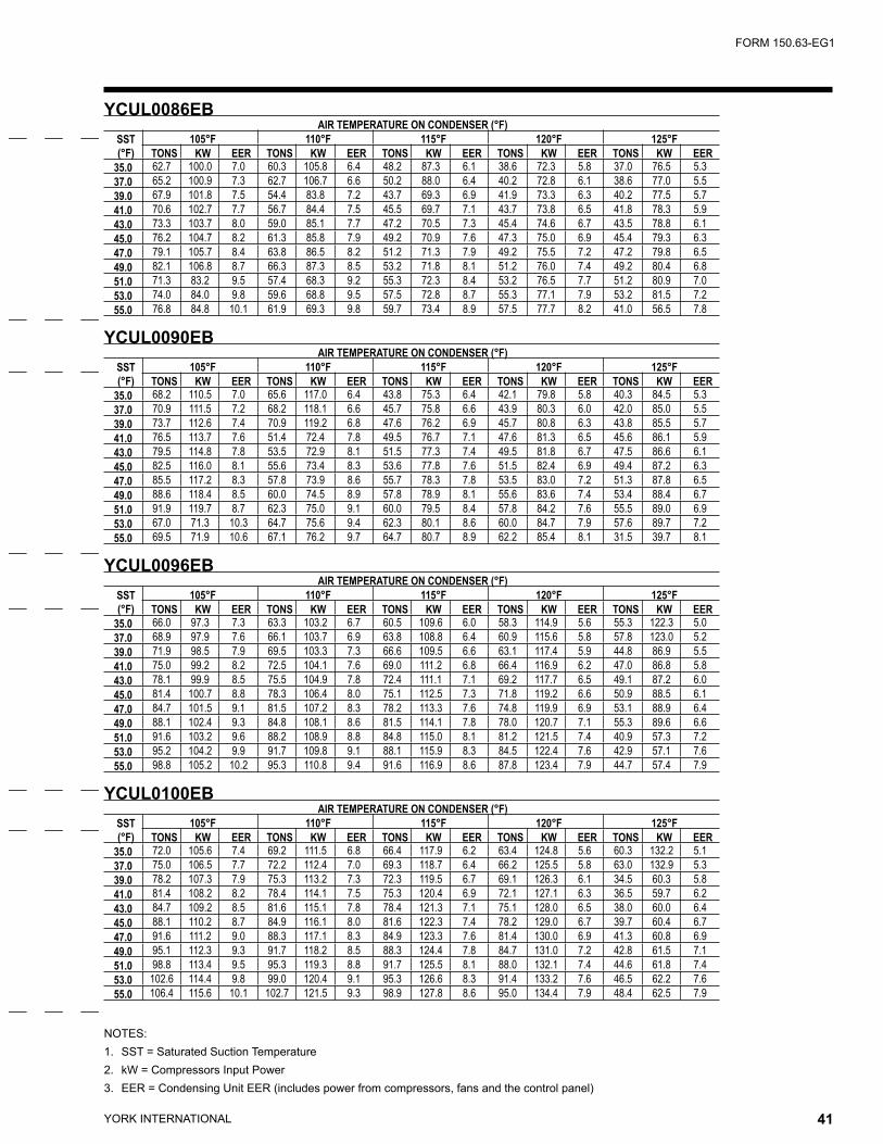
YORK INTERNATIONAL40 YORK INTERNATIONAL 41
FORM 150.63-EG1
NOTES:1. SST = Saturated Suction Temperature2. kW = Compressors Input Power3. EER = Condensing Unit EER (includes power from compressors, fans and the control panel)
YCUL0086EB AIR TEMPERATURE ON CONDENSER (°F)
SST(°F)
105°F 110°F 115°F 120°F 125°FTONS KW EER TONS KW EER TONS KW EER TONS KW EER TONS KW EER
35.0 62.7 100.0 7.0 60.3 105.8 6.4 48.2 87.3 6.1 38.6 72.3 5.8 37.0 76.5 5.337.0 65.2 100.9 7.3 62.7 106.7 6.6 50.2 88.0 6.4 40.2 72.8 6.1 38.6 77.0 5.539.0 67.9 101.8 7.5 54.4 83.8 7.2 43.7 69.3 6.9 41.9 73.3 6.3 40.2 77.5 5.741.0 70.6 102.7 7.7 56.7 84.4 7.5 45.5 69.7 7.1 43.7 73.8 6.5 41.8 78.3 5.943.0 73.3 103.7 8.0 59.0 85.1 7.7 47.2 70.5 7.3 45.4 74.6 6.7 43.5 78.8 6.145.0 76.2 104.7 8.2 61.3 85.8 7.9 49.2 70.9 7.6 47.3 75.0 6.9 45.4 79.3 6.347.0 79.1 105.7 8.4 63.8 86.5 8.2 51.2 71.3 7.9 49.2 75.5 7.2 47.2 79.8 6.549.0 82.1 106.8 8.7 66.3 87.3 8.5 53.2 71.8 8.1 51.2 76.0 7.4 49.2 80.4 6.851.0 71.3 83.2 9.5 57.4 68.3 9.2 55.3 72.3 8.4 53.2 76.5 7.7 51.2 80.9 7.053.0 74.0 84.0 9.8 59.6 68.8 9.5 57.5 72.8 8.7 55.3 77.1 7.9 53.2 81.5 7.255.0 76.8 84.8 10.1 61.9 69.3 9.8 59.7 73.4 8.9 57.5 77.7 8.2 41.0 56.5 7.8
YCUL0090EB AIR TEMPERATURE ON CONDENSER (°F)
SST(°F)
105°F 110°F 115°F 120°F 125°FTONS KW EER TONS KW EER TONS KW EER TONS KW EER TONS KW EER
35.0 68.2 110.5 7.0 65.6 117.0 6.4 43.8 75.3 6.4 42.1 79.8 5.8 40.3 84.5 5.337.0 70.9 111.5 7.2 68.2 118.1 6.6 45.7 75.8 6.6 43.9 80.3 6.0 42.0 85.0 5.539.0 73.7 112.6 7.4 70.9 119.2 6.8 47.6 76.2 6.9 45.7 80.8 6.3 43.8 85.5 5.741.0 76.5 113.7 7.6 51.4 72.4 7.8 49.5 76.7 7.1 47.6 81.3 6.5 45.6 86.1 5.943.0 79.5 114.8 7.8 53.5 72.9 8.1 51.5 77.3 7.4 49.5 81.8 6.7 47.5 86.6 6.145.0 82.5 116.0 8.1 55.6 73.4 8.3 53.6 77.8 7.6 51.5 82.4 6.9 49.4 87.2 6.347.0 85.5 117.2 8.3 57.8 73.9 8.6 55.7 78.3 7.8 53.5 83.0 7.2 51.3 87.8 6.549.0 88.6 118.4 8.5 60.0 74.5 8.9 57.8 78.9 8.1 55.6 83.6 7.4 53.4 88.4 6.751.0 91.9 119.7 8.7 62.3 75.0 9.1 60.0 79.5 8.4 57.8 84.2 7.6 55.5 89.0 6.953.0 67.0 71.3 10.3 64.7 75.6 9.4 62.3 80.1 8.6 60.0 84.7 7.9 57.6 89.7 7.255.0 69.5 71.9 10.6 67.1 76.2 9.7 64.7 80.7 8.9 62.2 85.4 8.1 31.5 39.7 8.1
YCUL0096EB AIR TEMPERATURE ON CONDENSER (°F)
SST(°F)
105°F 110°F 115°F 120°F 125°FTONS KW EER TONS KW EER TONS KW EER TONS KW EER TONS KW EER
35.0 66.0 97.3 7.3 63.3 103.2 6.7 60.5 109.6 6.0 58.3 114.9 5.6 55.3 122.3 5.037.0 68.9 97.9 7.6 66.1 103.7 6.9 63.8 108.8 6.4 60.9 115.6 5.8 57.8 123.0 5.239.0 71.9 98.5 7.9 69.5 103.3 7.3 66.6 109.5 6.6 63.1 117.4 5.9 44.8 86.9 5.541.0 75.0 99.2 8.2 72.5 104.1 7.6 69.0 111.2 6.8 66.4 116.9 6.2 47.0 86.8 5.843.0 78.1 99.9 8.5 75.5 104.9 7.8 72.4 111.1 7.1 69.2 117.7 6.5 49.1 87.2 6.045.0 81.4 100.7 8.8 78.3 106.4 8.0 75.1 112.5 7.3 71.8 119.2 6.6 50.9 88.5 6.147.0 84.7 101.5 9.1 81.5 107.2 8.3 78.2 113.3 7.6 74.8 119.9 6.9 53.1 88.9 6.449.0 88.1 102.4 9.3 84.8 108.1 8.6 81.5 114.1 7.8 78.0 120.7 7.1 55.3 89.6 6.651.0 91.6 103.2 9.6 88.2 108.9 8.8 84.8 115.0 8.1 81.2 121.5 7.4 40.9 57.3 7.253.0 95.2 104.2 9.9 91.7 109.8 9.1 88.1 115.9 8.3 84.5 122.4 7.6 42.9 57.1 7.655.0 98.8 105.2 10.2 95.3 110.8 9.4 91.6 116.9 8.6 87.8 123.4 7.9 44.7 57.4 7.9
YCUL0100EB AIR TEMPERATURE ON CONDENSER (°F)
SST(°F)
105°F 110°F 115°F 120°F 125°FTONS KW EER TONS KW EER TONS KW EER TONS KW EER TONS KW EER
35.0 72.0 105.6 7.4 69.2 111.5 6.8 66.4 117.9 6.2 63.4 124.8 5.6 60.3 132.2 5.137.0 75.0 106.5 7.7 72.2 112.4 7.0 69.3 118.7 6.4 66.2 125.5 5.8 63.0 132.9 5.339.0 78.2 107.3 7.9 75.3 113.2 7.3 72.3 119.5 6.7 69.1 126.3 6.1 34.5 60.3 5.841.0 81.4 108.2 8.2 78.4 114.1 7.5 75.3 120.4 6.9 72.1 127.1 6.3 36.5 59.7 6.243.0 84.7 109.2 8.5 81.6 115.1 7.8 78.4 121.3 7.1 75.1 128.0 6.5 38.0 60.0 6.445.0 88.1 110.2 8.7 84.9 116.1 8.0 81.6 122.3 7.4 78.2 129.0 6.7 39.7 60.4 6.747.0 91.6 111.2 9.0 88.3 117.1 8.3 84.9 123.3 7.6 81.4 130.0 6.9 41.3 60.8 6.949.0 95.1 112.3 9.3 91.7 118.2 8.5 88.3 124.4 7.8 84.7 131.0 7.2 42.8 61.5 7.151.0 98.8 113.4 9.5 95.3 119.3 8.8 91.7 125.5 8.1 88.0 132.1 7.4 44.6 61.8 7.453.0 102.6 114.4 9.8 99.0 120.4 9.1 95.3 126.6 8.3 91.4 133.2 7.6 46.5 62.2 7.655.0 106.4 115.6 10.1 102.7 121.5 9.3 98.9 127.8 8.6 95.0 134.4 7.9 48.4 62.5 7.9

YORK INTERNATIONAL42 YORK INTERNATIONAL 43
FORM 150.63-EG1
Ratings - HFC-407C (English Units)
NOTES:1. SST = Saturated Suction Temperature2. kW = Compressors Input Power3. EER = Condensing Unit EER (includes power from compressors, fans and the control panel)
YCUL0106EB AIR TEMPERATURE ON CONDENSER (°F)
SST(°F)
75°F 80°F 85°F 90°F 95°F 100°FTONS KW EER TONS KW EER TONS KW EER TONS KW EER TONS KW EER TONS KW EER
35.0 97.1 88.4 11.8 94.3 93.2 10.9 91.5 98.4 10.1 88.6 104.0 9.3 85.5 110.0 8.5 82.4 116.6 7.837.0 101.1 89.4 12.1 98.2 94.3 11.2 95.3 99.5 10.4 92.2 105.1 9.6 89.1 111.1 8.8 85.8 117.7 8.039.0 105.1 90.4 12.5 102.2 95.3 11.6 99.1 100.6 10.7 96.0 106.2 9.8 92.7 112.3 9.0 89.4 118.8 8.341.0 109.3 91.4 12.8 106.2 96.4 11.9 103.1 101.7 11.0 99.8 107.4 10.1 96.5 113.5 9.3 93.0 120.0 8.543.0 113.6 92.5 13.2 110.4 97.6 12.2 107.1 102.9 11.3 103.8 108.6 10.4 100.3 114.8 9.6 96.7 121.3 8.845.0 118.0 93.7 13.6 114.7 98.8 12.6 111.3 104.2 11.6 107.8 109.9 10.7 104.2 116.0 9.9 100.5 122.6 9.047.0 122.5 94.8 13.9 119.1 100.0 12.9 115.6 105.4 11.9 112.0 111.2 11.0 108.3 117.3 10.1 104.5 123.9 9.349.0 127.1 96.0 14.3 123.6 101.2 13.2 120.0 106.7 12.3 116.3 112.5 11.3 112.4 118.6 10.4 108.5 125.2 9.651.0 131.9 97.1 14.7 128.2 102.4 13.6 124.5 107.9 12.6 120.7 113.8 11.6 116.7 120.0 10.7 112.7 126.6 9.853.0 136.8 98.3 15.0 133.0 103.7 13.9 129.1 109.2 12.9 125.2 115.1 11.9 121.1 121.3 11.0 116.9 127.9 10.155.0 141.8 99.5 15.4 137.9 104.9 14.3 133.9 110.5 13.2 129.8 116.4 12.2 125.6 122.7 11.3 121.3 129.4 10.4
YCUL0120EB AIR TEMPERATURE ON CONDENSER (°F)
SST(°F)
75°F 80°F 85°F 90°F 95°F 100°FTONS KW EER TONS KW EER TONS KW EER TONS KW EER TONS KW EER TONS KW EER
35.0 109.1 96.0 11.9 106.0 101.4 11.0 102.8 107.1 10.2 99.4 113.3 9.3 95.9 120.1 8.6 92.3 127.5 7.837.0 113.7 97.0 12.2 110.5 102.4 11.4 107.1 108.1 10.5 103.6 114.3 9.7 100.0 121.0 8.9 96.3 128.4 8.139.0 118.3 98.0 12.6 115.0 103.4 11.7 111.6 109.2 10.8 108.0 115.4 10.0 104.3 122.1 9.2 100.4 129.5 8.441.0 123.1 99.1 13.0 119.7 104.6 12.1 116.1 110.3 11.2 112.5 116.5 10.3 108.6 123.3 9.5 104.6 130.7 8.743.0 128.0 100.4 13.4 124.5 105.8 12.4 120.8 111.5 11.5 117.0 117.7 10.6 113.1 124.5 9.8 109.0 131.8 8.945.0 133.1 101.6 13.8 129.4 107.0 12.8 125.6 112.8 11.8 121.7 119.0 10.9 117.6 125.8 10.1 113.4 133.1 9.247.0 138.2 102.8 14.1 134.4 108.3 13.1 130.5 114.2 12.2 126.5 120.4 11.3 122.3 127.1 10.4 117.9 134.4 9.549.0 143.5 104.2 14.5 139.6 109.7 13.5 135.6 115.5 12.5 131.4 121.8 11.6 127.1 128.5 10.7 122.6 135.8 9.851.0 148.9 105.5 14.9 144.9 111.1 13.9 140.8 116.9 12.9 136.5 123.2 11.9 132.1 129.9 11.0 127.5 137.1 10.153.0 154.5 106.9 15.3 150.4 112.5 14.2 146.1 118.3 13.2 141.7 124.6 12.2 137.1 131.3 11.3 132.4 138.6 10.455.0 160.3 108.3 15.7 156.0 113.9 14.6 151.6 119.8 13.6 147.0 126.1 12.6 142.3 132.9 11.6 137.5 140.1 10.7
YCUL0130EB AIR TEMPERATURE ON CONDENSER (°F)
SST(°F)
75°F 80°F 85°F 90°F 95°F 100°FTONS KW EER TONS KW EER TONS KW EER TONS KW EER TONS KW EER TONS KW EER
35.0 118.8 107.6 11.7 115.5 113.5 10.8 112.1 119.7 10.0 108.6 126.3 9.3 105.0 133.5 8.5 101.2 141.2 7.837.0 123.7 108.8 12.0 120.2 114.7 11.2 116.7 121.0 10.3 113.1 127.6 9.6 109.3 134.8 8.8 105.4 142.5 8.139.0 128.7 110.0 12.4 125.1 116.0 11.5 121.5 122.3 10.7 117.7 129.0 9.9 113.8 136.1 9.1 109.8 143.8 8.341.0 133.8 111.3 12.8 130.1 117.3 11.9 126.3 123.6 11.0 122.4 130.3 10.2 118.4 137.5 9.4 114.3 145.2 8.643.0 139.1 112.6 13.1 135.3 118.7 12.2 131.3 125.0 11.3 127.3 131.8 10.5 123.2 139.0 9.6 118.9 146.7 8.945.0 144.5 113.9 13.5 140.5 120.0 12.5 136.5 126.5 11.6 132.3 133.3 10.8 128.0 140.4 9.9 123.6 148.2 9.147.0 150.0 115.2 13.9 145.9 121.5 12.9 141.8 127.9 12.0 137.5 134.7 11.1 133.0 142.0 10.2 128.5 149.7 9.449.0 155.7 116.6 14.3 151.5 122.8 13.2 147.2 129.4 12.3 142.7 136.2 11.4 138.2 143.5 10.5 133.5 151.3 9.751.0 161.6 117.9 14.7 157.2 124.3 13.6 152.7 130.9 12.6 148.1 137.8 11.7 143.4 145.1 10.8 138.6 152.9 9.953.0 167.6 119.3 15.0 163.1 125.7 14.0 158.5 132.4 13.0 153.7 139.3 12.0 148.8 146.7 11.1 143.8 154.5 10.255.0 173.8 120.7 15.4 169.1 127.2 14.3 164.3 133.9 13.3 159.4 141.0 12.3 154.4 148.3 11.4 149.3 156.2 10.5
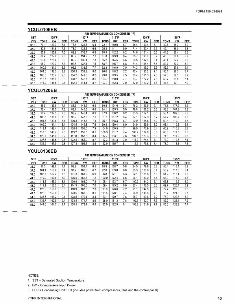
YORK INTERNATIONAL42 YORK INTERNATIONAL 43
FORM 150.63-EG1
NOTES:1. SST = Saturated Suction Temperature2. kW = Compressors Input Power3. EER = Condensing Unit EER (includes power from compressors, fans and the control panel)
YCUL0106EB AIR TEMPERATURE ON CONDENSER (°F)
SST(°F)
105°F 110°F 115°F 120°F 125°FTONS KW EER TONS KW EER TONS KW EER TONS KW EER TONS KW EER
35.0 79.1 123.7 7.1 75.7 131.5 6.4 72.1 140.0 5.7 68.4 149.4 5.1 40.5 85.7 5.037.0 82.5 124.8 7.3 78.9 132.6 6.6 75.3 141.1 5.9 71.4 150.4 5.3 42.4 86.0 5.339.0 85.9 125.9 7.5 82.2 133.7 6.8 78.5 142.2 6.2 74.6 151.4 5.5 44.3 86.4 5.541.0 89.4 127.2 7.8 85.7 134.9 7.1 81.8 143.3 6.4 65.7 116.8 6.2 46.3 86.8 5.743.0 93.0 128.4 8.0 89.2 136.1 7.3 85.2 144.5 6.6 68.5 117.6 6.4 48.4 87.2 5.945.0 96.7 129.7 8.3 92.8 137.4 7.5 88.7 145.7 6.8 71.4 118.4 6.6 50.7 87.3 6.247.0 100.5 131.0 8.5 96.5 138.6 7.7 92.3 146.9 7.0 74.3 119.3 6.9 52.9 87.8 6.449.0 104.5 132.3 8.8 100.3 139.9 8.0 96.0 148.2 7.2 77.4 120.2 7.1 55.1 88.3 6.751.0 108.5 133.7 9.0 104.2 141.3 8.2 99.8 149.5 7.5 80.4 121.3 7.3 57.3 89.1 6.953.0 112.7 135.0 9.3 108.2 142.7 8.5 103.7 150.9 7.7 83.7 122.2 7.6 59.7 89.6 7.155.0 116.9 136.5 9.5 112.4 144.1 8.7 107.7 152.3 7.9 87.0 123.2 7.8 44.5 57.1 7.9
YCUL0120EB AIR TEMPERATURE ON CONDENSER (°F)
SST(°F)
105°F 110°F 115°F 120°F 125°FTONS KW EER TONS KW EER TONS KW EER TONS KW EER TONS KW EER
35.0 88.5 135.6 7.1 84.6 144.6 6.4 80.5 154.6 5.7 76.2 165.5 5.1 71.8 177.5 4.537.0 92.4 136.5 7.3 88.4 145.5 6.6 84.1 155.3 5.9 79.8 166.2 5.3 53.3 107.3 5.339.0 96.4 137.5 7.6 92.2 146.4 6.9 87.9 156.2 6.2 83.3 167.1 5.5 55.1 109.5 5.341.0 100.5 138.6 7.9 96.2 147.5 7.1 91.7 157.2 6.4 87.1 167.9 5.7 57.7 109.7 5.643.0 104.7 139.8 8.1 100.3 148.6 7.4 95.7 158.3 6.7 90.9 168.8 6.0 60.4 110.0 5.845.0 109.0 141.1 8.4 104.5 149.8 7.6 99.8 159.4 6.9 94.9 169.8 6.2 63.1 110.3 6.147.0 113.4 142.4 8.7 108.8 151.0 7.9 104.0 160.5 7.1 99.0 170.9 6.4 65.9 110.8 6.349.0 118.0 143.7 9.0 113.2 152.3 8.1 108.3 161.7 7.4 103.2 172.0 6.6 68.8 111.3 6.651.0 122.7 145.0 9.2 117.8 153.6 8.4 112.7 163.1 7.6 107.5 173.3 6.9 71.8 111.9 6.853.0 127.5 146.5 9.5 122.5 155.0 8.7 117.3 164.3 7.9 111.9 174.4 7.1 74.9 112.5 7.155.0 132.5 147.9 9.8 127.3 156.4 8.9 122.0 165.7 8.1 116.5 175.8 7.4 78.0 113.1 7.3
YCUL0130EB AIR TEMPERATURE ON CONDENSER (°F)
SST(°F)
105°F 110°F 115°F 120°F 125°FTONS KW EER TONS KW EER TONS KW EER TONS KW EER TONS KW EER
35.0 97.3 149.6 7.1 93.2 158.7 6.5 88.9 168.7 5.8 84.5 179.6 5.2 56.4 116.4 5.237.0 101.4 150.9 7.4 97.2 160.0 6.7 92.8 169.8 6.0 88.3 180.6 5.4 58.9 117.0 5.439.0 105.7 152.2 7.6 101.3 161.2 6.9 96.8 171.1 6.3 92.1 181.8 5.6 61.2 118.4 5.541.0 110.0 153.6 7.9 105.5 162.6 7.2 100.9 172.4 6.5 96.1 183.0 5.8 64.0 118.9 5.843.0 114.5 155.0 8.1 109.9 164.0 7.4 105.1 173.7 6.7 100.2 184.3 6.1 66.8 119.5 6.045.0 119.1 156.5 8.4 114.3 165.5 7.6 109.4 175.2 6.9 87.4 146.5 6.5 69.7 120.1 6.247.0 123.8 158.0 8.6 118.9 167.0 7.9 113.9 176.6 7.2 91.1 147.5 6.8 72.7 120.8 6.549.0 128.6 159.6 8.9 123.6 168.5 8.1 118.5 178.1 7.4 94.9 148.5 7.0 75.7 121.5 6.751.0 133.6 161.2 9.1 128.5 170.1 8.4 123.1 179.7 7.6 98.7 149.6 7.2 78.9 122.3 6.953.0 138.7 162.9 9.4 133.4 171.7 8.6 128.0 181.3 7.8 102.7 150.7 7.5 82.2 123.1 7.255.0 144.0 164.5 9.7 138.5 173.4 8.9 132.9 182.9 8.1 106.8 151.9 7.7 85.5 123.9 7.4
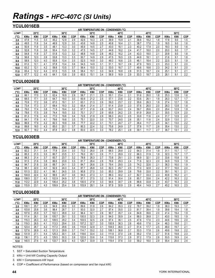
YORK INTERNATIONAL44 YORK INTERNATIONAL 45
FORM 150.63-EG1
Ratings - HFC-407C (SI Units)
NOTES:1. SST = Saturated Suction Temperature2. kWo = Unit kW Cooling Capacity Output3. kWi = Compressors kW Input4. COP = Coefficient of Performance (based on compressor and fan input kW)
YCUL0016EB AIR TEMPERATURE ON - CONDENSER (°C)
LCWT(°C)
25°C 30°C 35°C 40°C 45°C 50°CKWo KWi COP KWo KWi COP KWo KWi COP KWo KWi COP KWo KWi COP KWo KWi COP
2.0 47.8 11.5 3.3 45.2 12.9 2.9 42.6 14.3 2.5 39.9 15.9 2.1 36.6 18.2 1.8 17.8 9.0 1.53.0 49.5 11.6 3.4 46.9 12.9 3.0 43.6 14.8 2.5 40.8 16.4 2.1 38.7 17.8 1.9 18.5 9.0 1.64.0 50.9 11.9 3.5 48.1 13.3 3.0 45.9 14.5 2.7 43.0 16.1 2.3 40.2 17.9 2.0 19.3 9.0 1.65.0 52.8 11.9 3.6 50.4 13.0 3.2 47.5 14.5 2.7 44.6 16.2 2.4 41.7 18.0 2.0 20.0 9.0 1.76.0 54.8 11.9 3.7 51.8 13.3 3.2 48.8 14.8 2.8 46.2 16.2 2.4 43.3 18.0 2.1 20.8 9.0 1.87.0 56.8 12.0 3.9 53.8 13.3 3.3 50.7 14.9 2.9 47.5 16.5 2.5 44.9 18.1 2.1 21.6 9.1 1.88.0 58.9 12.0 4.0 55.8 13.4 3.5 52.5 14.9 3.0 49.3 16.6 2.5 46.1 18.4 2.2 22.5 9.1 1.99.0 61.0 12.1 4.1 57.8 13.4 3.6 54.5 14.9 3.1 51.1 16.7 2.6 47.9 18.5 2.3 23.3 9.1 2.0
10.0 63.2 12.1 4.2 59.8 13.5 3.7 56.4 15.0 3.2 53.0 16.7 2.7 49.6 18.6 2.3 24.2 9.1 2.011.0 65.4 12.2 4.4 61.9 13.5 3.8 58.4 15.1 3.3 54.9 16.8 2.8 51.5 18.7 2.4 25.1 9.1 2.112.0 67.7 12.2 4.5 64.1 13.6 3.9 60.5 15.1 3.4 56.9 16.9 2.9 53.3 18.7 2.5 26.1 9.1 2.2
YCUL0026EB AIR TEMPERATURE ON - CONDENSER (°C)
LCWT(°C)
25°C 30°C 35°C 40°C 45°C 50°CKWo KWi COP KWo KWi COP KWo KWi COP KWo KWi COP KWo KWi COP KWo KWi COP
2.0 66.1 17.0 3.3 62.4 18.9 2.9 58.7 21.1 2.5 55.1 23.4 2.1 51.6 26.0 1.8 25.3 12.6 1.63.0 68.5 17.1 3.5 64.7 19.0 3.0 60.9 21.2 2.5 57.1 23.6 2.2 53.6 26.1 1.9 26.3 12.7 1.74.0 70.9 17.2 3.6 67.0 19.1 3.1 63.1 21.3 2.6 59.3 23.7 2.2 55.6 26.3 1.9 27.4 12.7 1.85.0 73.4 17.3 3.7 69.4 19.3 3.2 65.4 21.4 2.7 61.4 23.9 2.3 57.6 26.5 2.0 28.3 12.8 1.86.0 76.0 17.4 3.8 71.9 19.4 3.2 67.7 21.6 2.8 63.7 24.0 2.4 59.7 26.6 2.0 29.4 12.9 1.97.0 78.6 17.5 3.9 74.4 19.5 3.3 70.1 21.7 2.9 65.9 24.2 2.5 61.9 26.8 2.1 30.5 12.9 2.08.0 81.3 17.6 4.0 77.0 19.6 3.4 72.6 21.9 2.9 68.3 24.3 2.5 33.9 11.6 2.4 31.7 12.9 2.09.0 84.1 17.8 4.1 79.6 19.8 3.5 75.1 22.0 3.0 70.7 24.5 2.6 35.1 11.6 2.4 32.9 13.0 2.1
10.0 86.9 17.9 4.2 82.3 19.9 3.6 77.7 22.2 3.1 73.1 24.7 2.7 36.4 11.7 2.5 34.1 13.0 2.211.0 89.8 18.0 4.3 85.0 20.1 3.7 80.3 22.4 3.2 75.6 24.9 2.7 37.8 11.7 2.6 35.4 13.0 2.212.0 92.7 18.2 4.4 87.8 20.2 3.8 83.0 22.5 3.3 78.2 25.1 2.8 39.1 11.7 2.7 36.7 13.1 2.3
YCUL0030EB AIR TEMPERATURE ON - CONDENSER (°C)
LCWT(°C)
25°C 30°C 35°C 40°C 45°C 50°CKWo KWi COP KWo KWi COP KWo KWi COP KWo KWi COP KWo KWi COP KWo KWi COP
2.0 82.2 21.1 3.4 77.8 23.4 3.0 73.2 26.0 2.6 68.5 28.8 2.2 64.3 31.4 1.9 31.1 15.7 1.73.0 85.3 21.3 3.5 80.7 23.5 3.1 76.0 26.1 2.6 71.1 28.9 2.2 66.3 31.9 1.9 32.3 15.7 1.74.0 88.3 21.4 3.7 83.7 23.7 3.2 78.8 26.3 2.7 73.8 29.1 2.3 68.9 32.1 2.0 33.6 15.8 1.85.0 91.5 21.6 3.8 86.6 23.9 3.3 81.7 26.4 2.8 76.6 29.3 2.4 71.6 32.3 2.0 34.9 15.9 1.96.0 94.7 21.8 3.9 89.7 24.1 3.3 84.7 26.6 2.9 79.4 29.5 2.5 74.2 32.6 2.1 36.3 16.0 1.97.0 98.1 22.0 4.0 92.9 24.3 3.4 87.7 26.8 3.0 82.3 29.7 2.5 77.0 32.8 2.2 37.7 16.0 2.08.0 101.5 22.2 4.1 96.1 24.5 3.5 90.8 27.0 3.0 85.3 29.9 2.6 79.8 33.0 2.2 39.1 16.1 2.19.0 104.9 22.4 4.2 99.5 24.7 3.6 94.0 27.3 3.1 88.3 30.2 2.7 82.7 33.3 2.3 40.6 16.2 2.1
10.0 108.5 22.7 4.3 102.9 24.9 3.7 97.1 27.5 3.2 91.4 30.4 2.8 85.7 33.6 2.4 42.2 16.3 2.211.0 112.2 22.9 4.4 106.4 25.2 3.8 100.5 27.8 3.3 94.6 30.7 2.8 88.8 33.8 2.4 43.7 16.3 2.312.0 115.9 23.1 4.5 109.9 25.4 3.9 103.9 28.1 3.4 97.9 30.9 2.9 48.4 14.9 2.7 45.2 16.5 2.3
YCUL0036EB AIR TEMPERATURE ON - CONDENSER (°C)
LCWT(°C)
25°C 30°C 35°C 40°C 45°C 50°CKWo KWi COP KWo KWi COP KWo KWi COP KWo KWi COP KWo KWi COP KWo KWi COP
2.0 100.1 25.7 3.5 94.9 28.6 3.0 89.6 31.8 2.6 84.2 35.3 2.2 78.7 39.2 1.9 38.3 19.3 1.73.0 103.8 25.8 3.6 98.4 28.7 3.1 93.0 32.0 2.7 87.4 35.5 2.3 81.7 39.4 1.9 39.8 19.4 1.84.0 107.6 25.9 3.7 102.1 28.9 3.2 96.4 32.1 2.8 90.7 35.7 2.4 84.8 39.6 2.0 41.4 19.4 1.95.0 111.4 26.1 3.9 105.7 29.1 3.3 100.0 32.3 2.9 94.0 35.9 2.4 88.0 39.8 2.1 43.0 19.5 1.96.0 115.3 26.3 4.0 109.5 29.2 3.4 103.5 32.5 2.9 97.4 36.1 2.5 47.8 17.6 2.3 44.6 19.6 2.07.0 119.3 26.5 4.1 113.3 29.4 3.5 107.2 32.7 3.0 100.9 36.3 2.6 49.6 17.6 2.4 46.3 19.6 2.18.0 123.4 26.7 4.2 117.3 29.6 3.6 110.9 32.9 3.1 104.5 36.5 2.7 51.4 17.7 2.5 48.0 19.7 2.19.0 127.6 26.9 4.3 121.3 29.9 3.7 114.7 33.2 3.2 108.1 36.8 2.7 53.3 17.8 2.6 49.8 19.8 2.2
10.0 131.9 27.1 4.4 125.3 30.1 3.8 118.6 33.4 3.3 111.8 37.0 2.8 55.2 17.8 2.7 51.6 19.8 2.311.0 136.1 27.3 4.5 129.5 30.3 3.9 122.6 33.6 3.4 115.6 37.3 2.9 57.2 17.9 2.8 53.5 19.9 2.412.0 140.5 27.6 4.6 133.7 30.6 4.0 126.7 33.9 3.5 119.4 37.6 3.0 59.2 18.0 2.9 55.4 20.0 2.4
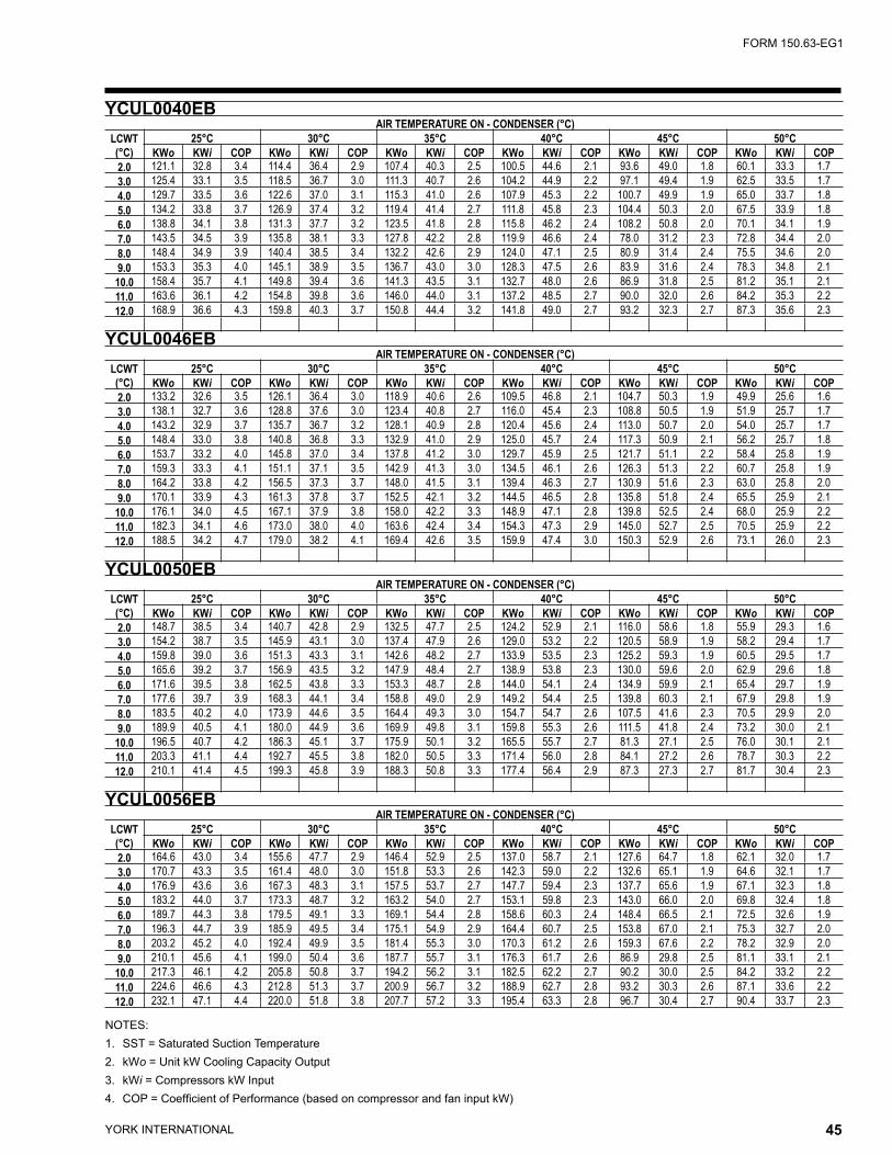
YORK INTERNATIONAL44 YORK INTERNATIONAL 45
FORM 150.63-EG1
NOTES:1. SST = Saturated Suction Temperature2. kWo = Unit kW Cooling Capacity Output3. kWi = Compressors kW Input4. COP = Coefficient of Performance (based on compressor and fan input kW)
YCUL0040EB AIR TEMPERATURE ON - CONDENSER (°C)
LCWT(°C)
25°C 30°C 35°C 40°C 45°C 50°CKWo KWi COP KWo KWi COP KWo KWi COP KWo KWi COP KWo KWi COP KWo KWi COP
2.0 121.1 32.8 3.4 114.4 36.4 2.9 107.4 40.3 2.5 100.5 44.6 2.1 93.6 49.0 1.8 60.1 33.3 1.73.0 125.4 33.1 3.5 118.5 36.7 3.0 111.3 40.7 2.6 104.2 44.9 2.2 97.1 49.4 1.9 62.5 33.5 1.74.0 129.7 33.5 3.6 122.6 37.0 3.1 115.3 41.0 2.6 107.9 45.3 2.2 100.7 49.9 1.9 65.0 33.7 1.85.0 134.2 33.8 3.7 126.9 37.4 3.2 119.4 41.4 2.7 111.8 45.8 2.3 104.4 50.3 2.0 67.5 33.9 1.86.0 138.8 34.1 3.8 131.3 37.7 3.2 123.5 41.8 2.8 115.8 46.2 2.4 108.2 50.8 2.0 70.1 34.1 1.97.0 143.5 34.5 3.9 135.8 38.1 3.3 127.8 42.2 2.8 119.9 46.6 2.4 78.0 31.2 2.3 72.8 34.4 2.08.0 148.4 34.9 3.9 140.4 38.5 3.4 132.2 42.6 2.9 124.0 47.1 2.5 80.9 31.4 2.4 75.5 34.6 2.09.0 153.3 35.3 4.0 145.1 38.9 3.5 136.7 43.0 3.0 128.3 47.5 2.6 83.9 31.6 2.4 78.3 34.8 2.1
10.0 158.4 35.7 4.1 149.8 39.4 3.6 141.3 43.5 3.1 132.7 48.0 2.6 86.9 31.8 2.5 81.2 35.1 2.111.0 163.6 36.1 4.2 154.8 39.8 3.6 146.0 44.0 3.1 137.2 48.5 2.7 90.0 32.0 2.6 84.2 35.3 2.212.0 168.9 36.6 4.3 159.8 40.3 3.7 150.8 44.4 3.2 141.8 49.0 2.7 93.2 32.3 2.7 87.3 35.6 2.3
YCUL0046EB AIR TEMPERATURE ON - CONDENSER (°C)
LCWT(°C)
25°C 30°C 35°C 40°C 45°C 50°CKWo KWi COP KWo KWi COP KWo KWi COP KWo KWi COP KWo KWi COP KWo KWi COP
2.0 133.2 32.6 3.5 126.1 36.4 3.0 118.9 40.6 2.6 109.5 46.8 2.1 104.7 50.3 1.9 49.9 25.6 1.63.0 138.1 32.7 3.6 128.8 37.6 3.0 123.4 40.8 2.7 116.0 45.4 2.3 108.8 50.5 1.9 51.9 25.7 1.74.0 143.2 32.9 3.7 135.7 36.7 3.2 128.1 40.9 2.8 120.4 45.6 2.4 113.0 50.7 2.0 54.0 25.7 1.75.0 148.4 33.0 3.8 140.8 36.8 3.3 132.9 41.0 2.9 125.0 45.7 2.4 117.3 50.9 2.1 56.2 25.7 1.86.0 153.7 33.2 4.0 145.8 37.0 3.4 137.8 41.2 3.0 129.7 45.9 2.5 121.7 51.1 2.2 58.4 25.8 1.97.0 159.3 33.3 4.1 151.1 37.1 3.5 142.9 41.3 3.0 134.5 46.1 2.6 126.3 51.3 2.2 60.7 25.8 1.98.0 164.2 33.8 4.2 156.5 37.3 3.7 148.0 41.5 3.1 139.4 46.3 2.7 130.9 51.6 2.3 63.0 25.8 2.09.0 170.1 33.9 4.3 161.3 37.8 3.7 152.5 42.1 3.2 144.5 46.5 2.8 135.8 51.8 2.4 65.5 25.9 2.1
10.0 176.1 34.0 4.5 167.1 37.9 3.8 158.0 42.2 3.3 148.9 47.1 2.8 139.8 52.5 2.4 68.0 25.9 2.211.0 182.3 34.1 4.6 173.0 38.0 4.0 163.6 42.4 3.4 154.3 47.3 2.9 145.0 52.7 2.5 70.5 25.9 2.212.0 188.5 34.2 4.7 179.0 38.2 4.1 169.4 42.6 3.5 159.9 47.4 3.0 150.3 52.9 2.6 73.1 26.0 2.3
YCUL0050EB AIR TEMPERATURE ON - CONDENSER (°C)
LCWT(°C)
25°C 30°C 35°C 40°C 45°C 50°CKWo KWi COP KWo KWi COP KWo KWi COP KWo KWi COP KWo KWi COP KWo KWi COP
2.0 148.7 38.5 3.4 140.7 42.8 2.9 132.5 47.7 2.5 124.2 52.9 2.1 116.0 58.6 1.8 55.9 29.3 1.63.0 154.2 38.7 3.5 145.9 43.1 3.0 137.4 47.9 2.6 129.0 53.2 2.2 120.5 58.9 1.9 58.2 29.4 1.74.0 159.8 39.0 3.6 151.3 43.3 3.1 142.6 48.2 2.7 133.9 53.5 2.3 125.2 59.3 1.9 60.5 29.5 1.75.0 165.6 39.2 3.7 156.9 43.5 3.2 147.9 48.4 2.7 138.9 53.8 2.3 130.0 59.6 2.0 62.9 29.6 1.86.0 171.6 39.5 3.8 162.5 43.8 3.3 153.3 48.7 2.8 144.0 54.1 2.4 134.9 59.9 2.1 65.4 29.7 1.97.0 177.6 39.7 3.9 168.3 44.1 3.4 158.8 49.0 2.9 149.2 54.4 2.5 139.8 60.3 2.1 67.9 29.8 1.98.0 183.5 40.2 4.0 173.9 44.6 3.5 164.4 49.3 3.0 154.7 54.7 2.6 107.5 41.6 2.3 70.5 29.9 2.09.0 189.9 40.5 4.1 180.0 44.9 3.6 169.9 49.8 3.1 159.8 55.3 2.6 111.5 41.8 2.4 73.2 30.0 2.1
10.0 196.5 40.7 4.2 186.3 45.1 3.7 175.9 50.1 3.2 165.5 55.7 2.7 81.3 27.1 2.5 76.0 30.1 2.111.0 203.3 41.1 4.4 192.7 45.5 3.8 182.0 50.5 3.3 171.4 56.0 2.8 84.1 27.2 2.6 78.7 30.3 2.212.0 210.1 41.4 4.5 199.3 45.8 3.9 188.3 50.8 3.3 177.4 56.4 2.9 87.3 27.3 2.7 81.7 30.4 2.3
YCUL0056EB AIR TEMPERATURE ON - CONDENSER (°C)
LCWT(°C)
25°C 30°C 35°C 40°C 45°C 50°CKWo KWi COP KWo KWi COP KWo KWi COP KWo KWi COP KWo KWi COP KWo KWi COP
2.0 164.6 43.0 3.4 155.6 47.7 2.9 146.4 52.9 2.5 137.0 58.7 2.1 127.6 64.7 1.8 62.1 32.0 1.73.0 170.7 43.3 3.5 161.4 48.0 3.0 151.8 53.3 2.6 142.3 59.0 2.2 132.6 65.1 1.9 64.6 32.1 1.74.0 176.9 43.6 3.6 167.3 48.3 3.1 157.5 53.7 2.7 147.7 59.4 2.3 137.7 65.6 1.9 67.1 32.3 1.85.0 183.2 44.0 3.7 173.3 48.7 3.2 163.2 54.0 2.7 153.1 59.8 2.3 143.0 66.0 2.0 69.8 32.4 1.86.0 189.7 44.3 3.8 179.5 49.1 3.3 169.1 54.4 2.8 158.6 60.3 2.4 148.4 66.5 2.1 72.5 32.6 1.97.0 196.3 44.7 3.9 185.9 49.5 3.4 175.1 54.9 2.9 164.4 60.7 2.5 153.8 67.0 2.1 75.3 32.7 2.08.0 203.2 45.2 4.0 192.4 49.9 3.5 181.4 55.3 3.0 170.3 61.2 2.6 159.3 67.6 2.2 78.2 32.9 2.09.0 210.1 45.6 4.1 199.0 50.4 3.6 187.7 55.7 3.1 176.3 61.7 2.6 86.9 29.8 2.5 81.1 33.1 2.1
10.0 217.3 46.1 4.2 205.8 50.8 3.7 194.2 56.2 3.1 182.5 62.2 2.7 90.2 30.0 2.5 84.2 33.2 2.211.0 224.6 46.6 4.3 212.8 51.3 3.7 200.9 56.7 3.2 188.9 62.7 2.8 93.2 30.3 2.6 87.1 33.6 2.212.0 232.1 47.1 4.4 220.0 51.8 3.8 207.7 57.2 3.3 195.4 63.3 2.8 96.7 30.4 2.7 90.4 33.7 2.3
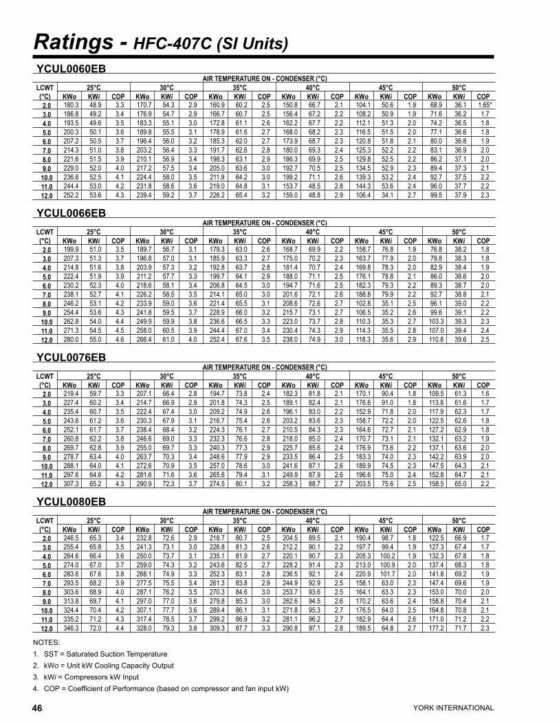
YORK INTERNATIONAL46 YORK INTERNATIONAL 47
FORM 150.63-EG1
Ratings - HFC-407C (SI Units)
NOTES:1. SST = Saturated Suction Temperature2. kWo = Unit kW Cooling Capacity Output3. kWi = Compressors kW Input4. COP = Coefficient of Performance (based on compressor and fan input kW)
YCUL0060EB AIR TEMPERATURE ON - CONDENSER (°C)
LCWT(°C)
25°C 30°C 35°C 40°C 45°C 50°CKWo KWi COP KWo KWi COP KWo KWi COP KWo KWi COP KWo KWi COP KWo KWi COP
2.0 180.3 48.9 3.3 170.7 54.3 2.9 160.9 60.2 2.5 150.8 66.7 2.1 104.1 50.6 1.9 68.9 36.1 1.65*3.0 186.8 49.2 3.4 176.9 54.7 2.9 166.7 60.7 2.5 156.4 67.2 2.2 108.2 50.9 1.9 71.6 36.2 1.74.0 193.5 49.6 3.5 183.3 55.1 3.0 172.8 61.1 2.6 162.2 67.7 2.2 112.1 51.3 2.0 74.2 36.5 1.85.0 200.3 50.1 3.6 189.8 55.5 3.1 178.9 61.6 2.7 168.0 68.2 2.3 116.5 51.5 2.0 77.1 36.6 1.86.0 207.2 50.5 3.7 196.4 56.0 3.2 185.3 62.0 2.7 173.9 68.7 2.3 120.8 51.8 2.1 80.0 36.8 1.97.0 214.3 51.0 3.8 203.2 56.4 3.3 191.7 62.6 2.8 180.0 69.3 2.4 125.3 52.2 2.2 83.1 36.9 2.08.0 221.6 51.5 3.9 210.1 56.9 3.4 198.3 63.1 2.9 186.3 69.9 2.5 129.8 52.5 2.2 86.2 37.1 2.09.0 229.0 52.0 4.0 217.2 57.5 3.4 205.0 63.6 3.0 192.7 70.5 2.5 134.5 52.9 2.3 89.4 37.3 2.1
10.0 236.6 52.5 4.1 224.4 58.0 3.5 211.9 64.2 3.0 199.2 71.1 2.6 139.3 53.2 2.4 92.7 37.5 2.211.0 244.4 53.0 4.2 231.8 58.6 3.6 219.0 64.8 3.1 153.7 48.5 2.8 144.3 53.6 2.4 96.0 37.7 2.212.0 252.2 53.6 4.3 239.4 59.2 3.7 226.2 65.4 3.2 159.0 48.8 2.9 106.4 34.1 2.7 99.5 37.9 2.3
YCUL0066EB AIR TEMPERATURE ON - CONDENSER (°C)
LCWT(°C)
25°C 30°C 35°C 40°C 45°C 50°CKWo KWi COP KWo KWi COP KWo KWi COP KWo KWi COP KWo KWi COP KWo KWi COP
2.0 199.9 51.0 3.5 189.7 56.7 3.1 179.3 63.0 2.6 168.7 69.9 2.2 158.7 76.8 1.9 76.8 38.2 1.83.0 207.3 51.3 3.7 196.8 57.0 3.1 185.9 63.3 2.7 175.0 70.2 2.3 163.7 77.9 2.0 79.8 38.3 1.84.0 214.8 51.6 3.8 203.9 57.3 3.2 192.8 63.7 2.8 181.4 70.7 2.4 169.8 78.3 2.0 82.9 38.4 1.95.0 222.4 51.9 3.9 211.2 57.7 3.3 199.7 64.1 2.9 188.0 71.1 2.5 176.1 78.8 2.1 86.0 38.6 2.06.0 230.2 52.3 4.0 218.6 58.1 3.4 206.8 64.5 3.0 194.7 71.6 2.5 182.3 79.3 2.2 89.3 38.7 2.07.0 238.1 52.7 4.1 226.2 58.5 3.5 214.1 65.0 3.0 201.6 72.1 2.6 188.8 79.9 2.2 92.7 38.8 2.18.0 246.2 53.1 4.2 233.9 59.0 3.6 221.4 65.5 3.1 208.6 72.6 2.7 102.8 35.1 2.5 96.1 39.0 2.29.0 254.4 53.6 4.3 241.8 59.5 3.7 228.9 66.0 3.2 215.7 73.1 2.7 106.5 35.2 2.6 99.6 39.1 2.2
10.0 262.8 54.0 4.4 249.9 59.9 3.8 236.6 66.5 3.3 223.0 73.7 2.8 110.3 35.3 2.7 103.3 39.3 2.311.0 271.3 54.5 4.5 258.0 60.5 3.9 244.4 67.0 3.4 230.4 74.3 2.9 114.3 35.5 2.8 107.0 39.4 2.412.0 280.0 55.0 4.6 266.4 61.0 4.0 252.4 67.6 3.5 238.0 74.9 3.0 118.3 35.6 2.9 110.8 39.6 2.5
YCUL0076EB AIR TEMPERATURE ON - CONDENSER (°C)
LCWT(°C)
25°C 30°C 35°C 40°C 45°C 50°CKWo KWi COP KWo KWi COP KWo KWi COP KWo KWi COP KWo KWi COP KWo KWi COP
2.0 219.4 59.7 3.3 207.1 66.4 2.8 194.7 73.8 2.4 182.3 81.8 2.1 170.1 90.4 1.8 109.5 61.3 1.63.0 227.4 60.2 3.4 214.7 66.9 2.9 201.8 74.3 2.5 189.1 82.4 2.1 176.6 91.0 1.8 113.8 61.6 1.74.0 235.4 60.7 3.5 222.4 67.4 3.0 209.2 74.9 2.6 196.1 83.0 2.2 152.9 71.8 2.0 117.9 62.3 1.75.0 243.6 61.2 3.6 230.3 67.9 3.1 216.7 75.4 2.6 203.2 83.6 2.3 158.7 72.2 2.0 122.5 62.6 1.86.0 252.1 61.7 3.7 238.4 68.4 3.2 224.3 76.1 2.7 210.5 84.3 2.3 164.6 72.7 2.1 127.2 62.9 1.87.0 260.8 62.2 3.8 246.6 69.0 3.3 232.3 76.6 2.8 218.0 85.0 2.4 170.7 73.1 2.1 132.1 63.2 1.98.0 269.7 62.8 3.9 255.0 69.7 3.3 240.3 77.3 2.9 225.7 85.6 2.4 176.9 73.6 2.2 137.1 63.6 2.09.0 278.7 63.4 4.0 263.7 70.3 3.4 248.6 77.9 2.9 233.5 86.4 2.5 183.3 74.0 2.3 142.2 63.9 2.0
10.0 288.1 64.0 4.1 272.6 70.9 3.5 257.0 78.6 3.0 241.6 87.1 2.6 189.9 74.5 2.3 147.5 64.3 2.111.0 297.6 64.6 4.2 281.6 71.6 3.6 265.6 79.4 3.1 249.9 87.9 2.6 196.6 75.0 2.4 152.8 64.7 2.112.0 307.3 65.2 4.3 290.9 72.3 3.7 274.5 80.1 3.2 258.3 88.7 2.7 203.5 75.6 2.5 158.5 65.0 2.2
YCUL0080EB AIR TEMPERATURE ON - CONDENSER (°C)
LCWT(°C)
25°C 30°C 35°C 40°C 45°C 50°CKWo KWi COP KWo KWi COP KWo KWi COP KWo KWi COP KWo KWi COP KWo KWi COP
2.0 246.5 65.3 3.4 232.8 72.6 2.9 218.7 80.7 2.5 204.5 89.5 2.1 190.4 98.7 1.8 122.5 66.9 1.73.0 255.4 65.8 3.5 241.3 73.1 3.0 226.8 81.3 2.6 212.2 90.1 2.2 197.7 99.4 1.9 127.3 67.4 1.74.0 264.6 66.4 3.6 250.0 73.7 3.1 235.1 81.9 2.7 220.1 90.7 2.3 205.3 100.2 1.9 132.3 67.8 1.85.0 274.0 67.0 3.7 259.0 74.3 3.2 243.6 82.5 2.7 228.2 91.4 2.3 213.0 100.9 2.0 137.4 68.3 1.86.0 283.6 67.6 3.8 268.1 74.9 3.3 252.3 83.1 2.8 236.5 92.1 2.4 220.9 101.7 2.0 141.8 69.2 1.97.0 293.5 68.2 3.9 277.5 75.5 3.4 261.3 83.8 2.9 244.9 92.9 2.5 158.1 63.0 2.3 147.4 69.6 1.98.0 303.6 68.9 4.0 287.1 76.2 3.5 270.3 84.6 3.0 253.7 93.6 2.5 164.1 63.3 2.3 153.0 70.0 2.09.0 313.8 69.7 4.1 297.0 77.0 3.6 279.8 85.3 3.0 262.6 94.5 2.6 170.2 63.6 2.4 158.8 70.4 2.1
10.0 324.4 70.4 4.2 307.1 77.7 3.6 289.4 86.1 3.1 271.8 95.3 2.7 176.5 64.0 2.5 164.8 70.8 2.111.0 335.2 71.2 4.3 317.4 78.5 3.7 299.2 86.9 3.2 281.1 96.2 2.7 182.9 64.4 2.6 171.0 71.2 2.212.0 346.3 72.0 4.4 328.0 79.3 3.8 309.3 87.7 3.3 290.8 97.1 2.8 189.5 64.8 2.7 177.2 71.7 2.3
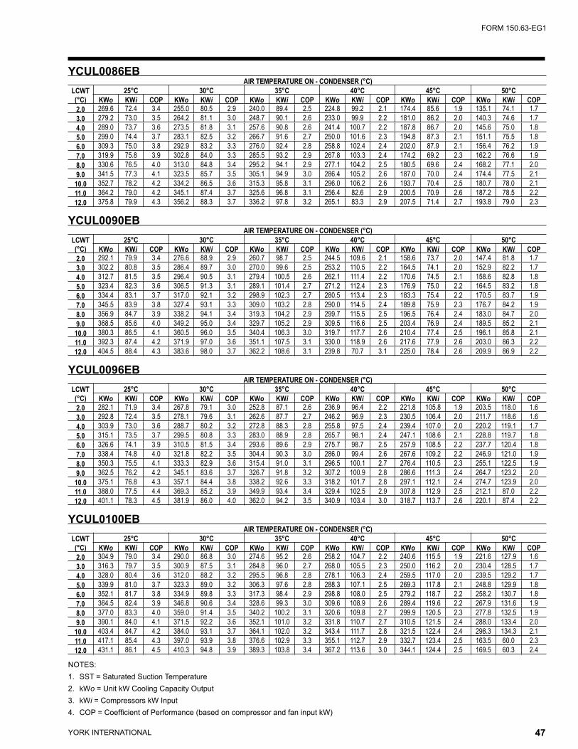
YORK INTERNATIONAL46 YORK INTERNATIONAL 47
FORM 150.63-EG1
NOTES:1. SST = Saturated Suction Temperature2. kWo = Unit kW Cooling Capacity Output3. kWi = Compressors kW Input4. COP = Coefficient of Performance (based on compressor and fan input kW)
YCUL0086EB AIR TEMPERATURE ON - CONDENSER (°C)
LCWT(°C)
25°C 30°C 35°C 40°C 45°C 50°CKWo KWi COP KWo KWi COP KWo KWi COP KWo KWi COP KWo KWi COP KWo KWi COP
2.0 269.6 72.4 3.4 255.0 80.5 2.9 240.0 89.4 2.5 224.8 99.2 2.1 174.4 85.6 1.9 135.1 74.1 1.73.0 279.2 73.0 3.5 264.2 81.1 3.0 248.7 90.1 2.6 233.0 99.9 2.2 181.0 86.2 2.0 140.3 74.6 1.74.0 289.0 73.7 3.6 273.5 81.8 3.1 257.6 90.8 2.6 241.4 100.7 2.2 187.8 86.7 2.0 145.6 75.0 1.85.0 299.0 74.4 3.7 283.1 82.5 3.2 266.7 91.6 2.7 250.0 101.6 2.3 194.8 87.3 2.1 151.1 75.5 1.86.0 309.3 75.0 3.8 292.9 83.2 3.3 276.0 92.4 2.8 258.8 102.4 2.4 202.0 87.9 2.1 156.4 76.2 1.97.0 319.9 75.8 3.9 302.8 84.0 3.3 285.5 93.2 2.9 267.8 103.3 2.4 174.2 69.2 2.3 162.2 76.6 1.98.0 330.6 76.5 4.0 313.0 84.8 3.4 295.2 94.1 2.9 277.1 104.2 2.5 180.5 69.6 2.4 168.2 77.1 2.09.0 341.5 77.3 4.1 323.5 85.7 3.5 305.1 94.9 3.0 286.4 105.2 2.6 187.0 70.0 2.4 174.4 77.5 2.1
10.0 352.7 78.2 4.2 334.2 86.5 3.6 315.3 95.8 3.1 296.0 106.2 2.6 193.7 70.4 2.5 180.7 78.0 2.111.0 364.2 79.0 4.2 345.1 87.4 3.7 325.6 96.8 3.1 256.4 82.6 2.9 200.5 70.9 2.6 187.2 78.5 2.212.0 375.8 79.9 4.3 356.2 88.3 3.7 336.2 97.8 3.2 265.1 83.3 2.9 207.5 71.4 2.7 193.8 79.0 2.3
YCUL0090EB AIR TEMPERATURE ON - CONDENSER (°C)
LCWT(°C)
25°C 30°C 35°C 40°C 45°C 50°CKWo KWi COP KWo KWi COP KWo KWi COP KWo KWi COP KWo KWi COP KWo KWi COP
2.0 292.1 79.9 3.4 276.6 88.9 2.9 260.7 98.7 2.5 244.5 109.6 2.1 158.6 73.7 2.0 147.4 81.8 1.73.0 302.2 80.8 3.5 286.4 89.7 3.0 270.0 99.6 2.5 253.2 110.5 2.2 164.5 74.1 2.0 152.9 82.2 1.74.0 312.7 81.5 3.5 296.4 90.5 3.1 279.4 100.5 2.6 262.1 111.4 2.2 170.6 74.5 2.1 158.6 82.8 1.85.0 323.4 82.3 3.6 306.5 91.3 3.1 289.1 101.4 2.7 271.2 112.4 2.3 176.9 75.0 2.2 164.5 83.2 1.86.0 334.4 83.1 3.7 317.0 92.1 3.2 298.9 102.3 2.7 280.5 113.4 2.3 183.3 75.4 2.2 170.5 83.7 1.97.0 345.5 83.9 3.8 327.4 93.1 3.3 309.0 103.2 2.8 290.0 114.5 2.4 189.8 75.9 2.3 176.7 84.2 1.98.0 356.9 84.7 3.9 338.2 94.1 3.4 319.3 104.2 2.9 299.7 115.5 2.5 196.5 76.4 2.4 183.0 84.7 2.09.0 368.5 85.6 4.0 349.2 95.0 3.4 329.7 105.2 2.9 309.5 116.6 2.5 203.4 76.9 2.4 189.5 85.2 2.1
10.0 380.3 86.5 4.1 360.5 96.0 3.5 340.4 106.3 3.0 319.7 117.7 2.6 210.4 77.4 2.5 196.1 85.8 2.111.0 392.3 87.4 4.2 371.9 97.0 3.6 351.1 107.5 3.1 330.0 118.9 2.6 217.6 77.9 2.6 203.0 86.3 2.212.0 404.5 88.4 4.3 383.6 98.0 3.7 362.2 108.6 3.1 239.8 70.7 3.1 225.0 78.4 2.6 209.9 86.9 2.2
YCUL0096EB AIR TEMPERATURE ON - CONDENSER (°C)
LCWT(°C)
25°C 30°C 35°C 40°C 45°C 50°CKWo KWi COP KWo KWi COP KWo KWi COP KWo KWi COP KWo KWi COP KWo KWi COP
2.0 282.1 71.9 3.4 267.8 79.1 3.0 252.8 87.1 2.6 236.9 96.4 2.2 221.8 105.8 1.9 203.5 118.0 1.63.0 292.8 72.4 3.5 278.1 79.6 3.1 262.6 87.7 2.7 246.2 96.9 2.3 230.5 106.4 2.0 211.7 118.6 1.64.0 303.9 73.0 3.6 288.7 80.2 3.2 272.8 88.3 2.8 255.8 97.5 2.4 239.4 107.0 2.0 220.2 119.1 1.75.0 315.1 73.5 3.7 299.5 80.8 3.3 283.0 88.9 2.8 265.7 98.1 2.4 247.1 108.6 2.1 228.8 119.7 1.86.0 326.6 74.1 3.9 310.5 81.5 3.4 293.6 89.6 2.9 275.7 98.7 2.5 257.9 108.5 2.2 237.7 120.4 1.87.0 338.4 74.8 4.0 321.8 82.2 3.5 304.4 90.3 3.0 286.0 99.4 2.6 267.6 109.2 2.2 246.9 121.0 1.98.0 350.3 75.5 4.1 333.3 82.9 3.6 315.4 91.0 3.1 296.5 100.1 2.7 276.4 110.5 2.3 255.1 122.5 1.99.0 362.5 76.2 4.2 345.1 83.6 3.7 326.7 91.8 3.2 307.2 100.9 2.8 286.6 111.3 2.4 264.7 123.2 2.0
10.0 375.1 76.8 4.3 357.1 84.4 3.8 338.2 92.6 3.3 318.2 101.7 2.8 297.1 112.1 2.4 274.7 123.9 2.011.0 388.0 77.5 4.4 369.3 85.2 3.9 349.9 93.4 3.4 329.4 102.5 2.9 307.8 112.9 2.5 212.1 87.0 2.212.0 401.1 78.3 4.5 381.9 86.0 4.0 362.0 94.2 3.5 340.9 103.4 3.0 318.7 113.7 2.6 220.1 87.4 2.2
YCUL0100EB AIR TEMPERATURE ON - CONDENSER (°C)
LCWT(°C)
25°C 30°C 35°C 40°C 45°C 50°CKWo KWi COP KWo KWi COP KWo KWi COP KWo KWi COP KWo KWi COP KWo KWi COP
2.0 304.9 79.0 3.4 290.0 86.8 3.0 274.6 95.2 2.6 258.2 104.7 2.2 240.6 115.5 1.9 221.6 127.9 1.63.0 316.3 79.7 3.5 300.9 87.5 3.1 284.8 96.0 2.7 268.0 105.5 2.3 250.0 116.2 2.0 230.4 128.5 1.74.0 328.0 80.4 3.6 312.0 88.2 3.2 295.5 96.8 2.8 278.1 106.3 2.4 259.5 117.0 2.0 239.5 129.2 1.75.0 339.9 81.0 3.7 323.3 89.0 3.2 306.3 97.6 2.8 288.3 107.1 2.5 269.3 117.8 2.1 248.8 129.9 1.86.0 352.1 81.7 3.8 334.9 89.8 3.3 317.3 98.4 2.9 298.8 108.0 2.5 279.2 118.7 2.2 258.2 130.7 1.87.0 364.5 82.4 3.9 346.8 90.6 3.4 328.6 99.3 3.0 309.6 108.9 2.6 289.4 119.6 2.2 267.9 131.6 1.98.0 377.0 83.3 4.0 359.0 91.4 3.5 340.2 100.2 3.1 320.6 109.8 2.7 299.9 120.5 2.3 277.8 132.5 1.99.0 390.1 84.0 4.1 371.5 92.2 3.6 352.1 101.0 3.2 331.8 110.7 2.7 310.5 121.5 2.4 288.0 133.4 2.0
10.0 403.4 84.7 4.2 384.0 93.1 3.7 364.1 102.0 3.2 343.4 111.7 2.8 321.5 122.4 2.4 298.3 134.3 2.111.0 417.1 85.4 4.3 397.0 93.9 3.8 376.6 102.9 3.3 355.1 112.7 2.9 332.7 123.4 2.5 163.5 60.0 2.312.0 431.1 86.1 4.5 410.3 94.8 3.9 389.3 103.8 3.4 367.2 113.6 3.0 344.1 124.4 2.5 169.5 60.3 2.4
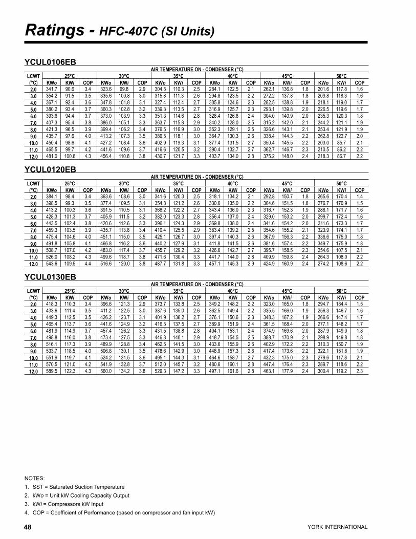
YORK INTERNATIONAL48 YORK INTERNATIONAL 49
FORM 150.63-EG1
Ratings - HFC-407C (SI Units)
NOTES:1. SST = Saturated Suction Temperature2. kWo = Unit kW Cooling Capacity Output3. kWi = Compressors kW Input4. COP = Coefficient of Performance (based on compressor and fan input kW)
YCUL0106EB AIR TEMPERATURE ON - CONDENSER (°C)
LCWT(°C)
25°C 30°C 35°C 40°C 45°C 50°CKWo KWi COP KWo KWi COP KWo KWi COP KWo KWi COP KWo KWi COP KWo KWi COP
2.0 341.7 90.6 3.4 323.6 99.8 2.9 304.5 110.3 2.5 284.1 122.5 2.1 262.1 136.8 1.8 201.6 117.8 1.63.0 354.2 91.5 3.5 335.6 100.8 3.0 315.8 111.3 2.6 294.8 123.5 2.2 272.2 137.8 1.8 209.8 118.3 1.64.0 367.1 92.4 3.6 347.8 101.8 3.1 327.4 112.4 2.7 305.8 124.6 2.3 282.5 138.8 1.9 218.1 119.0 1.75.0 380.2 93.4 3.7 360.3 102.8 3.2 339.3 113.5 2.7 316.9 125.7 2.3 293.1 139.8 2.0 226.5 119.6 1.76.0 393.6 94.4 3.7 373.0 103.9 3.3 351.3 114.6 2.8 328.4 126.8 2.4 304.0 140.9 2.0 235.3 120.3 1.87.0 407.3 95.4 3.8 386.0 105.1 3.3 363.7 115.8 2.9 340.2 128.0 2.5 315.2 142.0 2.1 244.2 121.1 1.98.0 421.3 96.5 3.9 399.4 106.2 3.4 376.5 116.9 3.0 352.3 129.1 2.5 326.6 143.1 2.1 253.4 121.9 1.99.0 435.7 97.6 4.0 413.2 107.3 3.5 389.5 118.1 3.0 364.7 130.3 2.6 338.4 144.3 2.2 262.8 122.7 2.0
10.0 450.4 98.6 4.1 427.2 108.4 3.6 402.9 119.3 3.1 377.4 131.5 2.7 350.4 145.5 2.2 203.0 85.7 2.111.0 465.5 99.7 4.2 441.6 109.6 3.7 416.6 120.5 3.2 390.4 132.7 2.7 362.7 146.7 2.3 210.5 86.2 2.212.0 481.0 100.8 4.3 456.4 110.8 3.8 430.7 121.7 3.3 403.7 134.0 2.8 375.2 148.0 2.4 218.3 86.7 2.2
YCUL0120EB AIR TEMPERATURE ON - CONDENSER (°C)
LCWT(°C)
25°C 30°C 35°C 40°C 45°C 50°CKWo KWi COP KWo KWi COP KWo KWi COP KWo KWi COP KWo KWi COP KWo KWi COP
2.0 384.1 98.4 3.4 363.6 108.6 3.0 341.6 120.3 2.5 318.1 134.2 2.1 292.8 150.7 1.8 265.6 170.4 1.43.0 398.5 99.3 3.5 377.4 109.5 3.1 354.8 121.2 2.6 330.6 135.0 2.2 304.6 151.5 1.8 276.7 170.9 1.54.0 413.2 100.3 3.6 391.5 110.5 3.1 368.2 122.2 2.7 343.4 136.0 2.3 316.7 152.3 1.9 288.1 171.7 1.65.0 428.3 101.3 3.7 405.9 111.5 3.2 382.0 123.3 2.8 356.4 137.0 2.4 329.0 153.2 2.0 299.7 172.4 1.66.0 443.5 102.4 3.8 420.6 112.6 3.3 396.1 124.3 2.9 369.8 138.0 2.4 341.6 154.2 2.0 311.6 173.3 1.77.0 459.3 103.5 3.9 435.7 113.8 3.4 410.4 125.5 2.9 383.4 139.2 2.5 354.6 155.2 2.1 323.9 174.1 1.78.0 475.4 104.6 4.0 451.1 115.0 3.5 425.1 126.7 3.0 397.4 140.3 2.6 367.9 156.3 2.2 336.6 175.0 1.89.0 491.8 105.8 4.1 466.8 116.2 3.6 440.2 127.9 3.1 411.8 141.5 2.6 381.6 157.4 2.2 349.7 175.9 1.8
10.0 508.7 107.0 4.2 483.0 117.4 3.7 455.7 129.2 3.2 426.6 142.7 2.7 395.7 158.5 2.3 254.6 107.5 2.111.0 526.0 108.2 4.3 499.6 118.7 3.8 471.6 130.4 3.3 441.7 144.0 2.8 409.9 159.8 2.4 264.3 108.0 2.212.0 543.6 109.5 4.4 516.6 120.0 3.8 487.7 131.8 3.3 457.1 145.3 2.9 424.9 160.9 2.4 274.2 108.6 2.2
YCUL0130EB AIR TEMPERATURE ON - CONDENSER (°C)
LCWT(°C)
25°C 30°C 35°C 40°C 45°C 50°CKWo KWi COP KWo KWi COP KWo KWi COP KWo KWi COP KWo KWi COP KWo KWi COP
2.0 418.3 110.3 3.4 396.6 121.3 2.9 373.7 133.8 2.5 349.2 148.2 2.2 323.0 165.0 1.8 294.7 184.4 1.53.0 433.6 111.4 3.5 411.2 122.5 3.0 387.6 135.0 2.6 362.5 149.4 2.2 335.5 166.0 1.9 256.3 146.7 1.64.0 449.3 112.5 3.5 426.2 123.7 3.1 401.9 136.2 2.7 376.1 150.6 2.3 348.3 167.2 1.9 266.6 147.4 1.75.0 465.4 113.7 3.6 441.6 124.9 3.2 416.5 137.5 2.7 389.9 151.9 2.4 361.5 168.4 2.0 277.1 148.2 1.76.0 481.9 114.9 3.7 457.4 126.2 3.3 431.5 138.8 2.8 404.1 153.1 2.4 374.9 169.6 2.0 287.9 149.0 1.87.0 498.8 116.0 3.8 473.4 127.5 3.3 446.8 140.1 2.9 418.7 154.5 2.5 388.7 170.9 2.1 298.9 149.8 1.88.0 516.1 117.3 3.9 489.9 128.8 3.4 462.5 141.5 3.0 433.6 155.9 2.6 402.9 172.2 2.2 310.3 150.7 1.99.0 533.7 118.5 4.0 506.8 130.1 3.5 478.6 142.9 3.0 448.9 157.3 2.6 417.4 173.6 2.2 322.1 151.6 1.9
10.0 551.9 119.7 4.1 524.2 131.5 3.6 495.1 144.3 3.1 464.6 158.7 2.7 432.3 175.0 2.3 279.6 117.8 2.111.0 570.5 121.0 4.2 541.9 132.8 3.7 512.0 145.7 3.2 480.6 160.1 2.8 447.4 176.4 2.3 289.7 118.6 2.212.0 589.5 122.3 4.3 560.0 134.2 3.8 529.3 147.2 3.3 497.1 161.6 2.8 463.1 177.9 2.4 300.4 119.2 2.3

YORK INTERNATIONAL48 YORK INTERNATIONAL 49
FORM 150.63-EG1

YORK INTERNATIONAL50 YORK INTERNATIONAL 51
FORM 150.63-EG1
Part Load Ratings - R-22 (English Units)YCUL0016EC
%DISPL.
AMBIENTDEG F TONS COMPR
kW EER
100.0 95.0 15.2 14.1 10.850.0 69.2 8.7 5.1 16.1
YCUL0030EC%
DISPL.AMBIENT
DEG F TONS COMPRkW EER
100.0 95.0 25.9 25.2 11.150.0 69.0 14.6 9.2 16.6
YCUL0040EC%
DISPL.AMBIENT
DEG F TONS COMPRkW EER
100.0 95.0 37.7 39.8 10.666.7 79.8 28.1 20.5 14.533.3 59.2 15.2 8.3 18.8
YCUL0050EC%
DISPL.AMBIENT
DEG F TONS COMPRkW EER
100.0 95.0 46.9 45.8 11.078.2 84.4 38.6 30.9 12.750.0 68.9 26.5 16.5 16.528.2 55.0 15.3 8.5 18.6
YCUL0060EC%
DISPL.AMBIENT
DEG F TONS COMPRkW EER
100.0 95.0 56.2 59.2 10.476.5 84.5 46.4 39.9 12.250.0 69.0 31.9 21.3 15.926.5 55.0 18.4 10.3 18.8
YCUL0076EC%
DISPL.AMBIENT
DEG F TONS COMPRkW EER
100.0 95.0 68.9 71.9 10.585.5 88.4 61.2 55.4 11.866.7 79.7 51.3 36.7 14.252.2 69.7 39.8 28.1 15.133.3 59.3 27.9 14.5 18.718.8 55.0 15.5 8.2 18.8
YCUL0086EC%
DISPL.AMBIENT
DEG F TONS COMPRkW EER
100.0 95.0 83.6 88.6 10.584.3 88.3 74.3 68.3 11.966.7 79.6 62.2 45.1 14.451.0 69.4 47.9 35.2 14.933.3 59.0 33.5 18.2 18.617.7 55.0 18.6 9.6 19.7
YCUL0026EC%
DISPL.AMBIENT
DEG F TONS COMPRkW EER
100.0 95.0 20.8 20.3 10.850.0 69.3 11.9 7.1 16.7
YCUL0036EC%
DISPL.AMBIENT
DEG F TONS COMPRkW EER
100.0 95.0 31.2 31.2 11.050.0 68.7 17.5 11.2 16.6
YCUL0046EC%
DISPL.AMBIENT
DEG F TONS COMPRkW EER
100.0 95.0 42.3 39.5 11.375.0 83.2 34.0 24.9 13.450.0 68.9 23.9 13.9 17.125.0 55.0 12.6 6.0 20.4
YCUL0056EC%
DISPL.AMBIENT
DEG F TONS COMPRkW EER
100.0 95.0 51.7 51.3 10.975.0 83.4 41.7 32.7 13.150.0 68.9 29.3 18.8 16.325.0 55.0 15.5 8.4 18.9
YCUL0066EC%
DISPL.AMBIENT
DEG F TONS COMPRkW EER
100.0 95.0 62.2 62.1 11.075.0 83.3 50.0 39.2 13.450.0 68.7 34.9 22.4 16.625.0 55.0 18.4 9.9 19.6
YCUL0080EC%
DISPL.AMBIENT
DEG F TONS COMPRkW EER
100.0 95.0 77.0 78.8 10.883.3 87.6 67.5 58.6 12.466.7 79.5 57.1 40.8 14.450.0 68.6 43.1 29.7 15.633.3 59.0 30.8 16.9 18.216.7 55.0 15.6 8.2 18.9
YCUL0090EC%
DISPL.AMBIENT
DEG F TONS COMPRkW EER
100.0 95.0 90.1 97.9 10.383.3 87.8 79.2 72.0 12.166.7 79.8 67.2 49.2 14.450.0 68.6 50.5 36.2 15.333.3 59.1 36.2 19.5 19.016.7 55.0 18.4 9.4 19.8
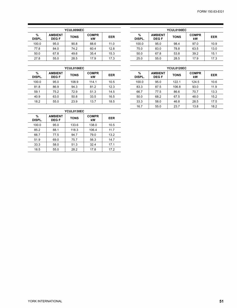
YORK INTERNATIONAL50 YORK INTERNATIONAL 51
FORM 150.63-EG1
YCUL0096EC%
DISPL.AMBIENT
DEG F TONS COMPRkW EER
100.0 95.0 90.8 88.6 11.077.8 84.0 74.2 60.4 12.850.0 67.8 49.6 35.4 15.327.8 55.0 28.5 17.9 17.3
YCUL0106EC%
DISPL.AMBIENT
DEG F TONS COMPRkW EER
100.0 95.0 108.9 114.1 10.581.8 86.9 94.3 81.2 12.359.1 75.2 72.9 51.3 14.540.9 63.0 50.8 33.5 16.518.2 55.0 23.9 13.7 18.5
YCUL0130EC%
DISPL.AMBIENT
DEG F TONS COMPRkW EER
100.0 95.0 133.6 138.0 10.585.2 88.1 118.3 106.4 11.766.7 77.5 94.7 79.0 13.251.9 69.0 75.7 56.3 14.733.3 58.0 51.3 32.4 17.118.5 55.0 28.2 17.8 17.2
YCUL0100EC%
DISPL.AMBIENT
DEG F TONS COMPRkW EER
100.0 95.0 98.4 97.0 10.975.0 83.0 78.8 63.5 13.050.0 67.8 53.8 39.2 15.125.0 55.0 28.5 17.9 17.3
YCUL0120EC%
DISPL.AMBIENT
DEG F TONS COMPRkW EER
100.0 95.0 122.1 124.5 10.683.3 87.5 106.8 93.0 11.966.7 77.5 86.6 70.7 13.350.0 68.2 67.5 48.0 15.233.3 58.0 46.8 28.5 17.516.7 55.0 23.7 13.8 18.2
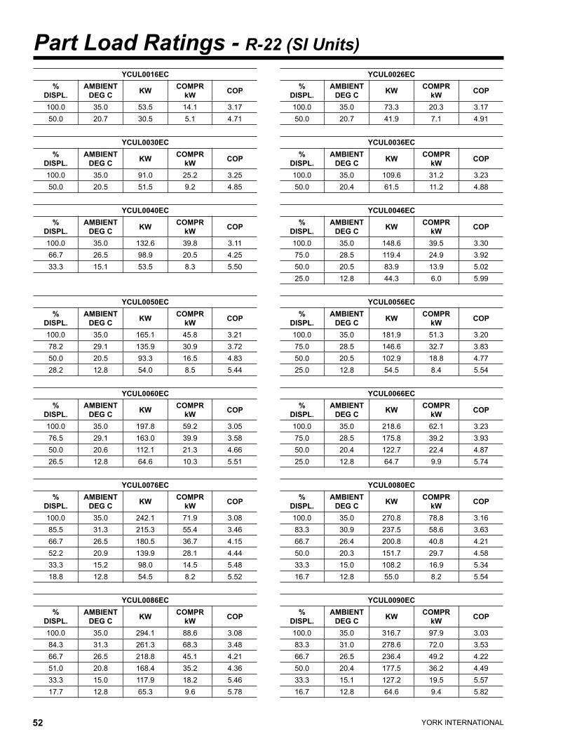
YORK INTERNATIONAL52 YORK INTERNATIONAL 53
FORM 150.63-EG1
Part Load Ratings - R-22 (SI Units)YCUL0016EC
%DISPL.
AMBIENTDEG C KW COMPR
kW COP
100.0 35.0 53.5 14.1 3.1750.0 20.7 30.5 5.1 4.71
YCUL0030EC%
DISPL.AMBIENT
DEG C KW COMPRkW COP
100.0 35.0 91.0 25.2 3.2550.0 20.5 51.5 9.2 4.85
YCUL0040EC%
DISPL.AMBIENT
DEG C KW COMPRkW COP
100.0 35.0 132.6 39.8 3.1166.7 26.5 98.9 20.5 4.2533.3 15.1 53.5 8.3 5.50
YCUL0050EC%
DISPL.AMBIENT
DEG C KW COMPRkW COP
100.0 35.0 165.1 45.8 3.2178.2 29.1 135.9 30.9 3.7250.0 20.5 93.3 16.5 4.8328.2 12.8 54.0 8.5 5.44
YCUL0060EC%
DISPL.AMBIENT
DEG C KW COMPRkW COP
100.0 35.0 197.8 59.2 3.0576.5 29.1 163.0 39.9 3.5850.0 20.6 112.1 21.3 4.6626.5 12.8 64.6 10.3 5.51
YCUL0076EC%
DISPL.AMBIENT
DEG C KW COMPRkW COP
100.0 35.0 242.1 71.9 3.0885.5 31.3 215.3 55.4 3.4666.7 26.5 180.5 36.7 4.1552.2 20.9 139.9 28.1 4.4433.3 15.2 98.0 14.5 5.4818.8 12.8 54.5 8.2 5.52
YCUL0086EC%
DISPL.AMBIENT
DEG C KW COMPRkW COP
100.0 35.0 294.1 88.6 3.0884.3 31.3 261.3 68.3 3.4866.7 26.5 218.8 45.1 4.2151.0 20.8 168.4 35.2 4.3633.3 15.0 117.9 18.2 5.4617.7 12.8 65.3 9.6 5.78
YCUL0026EC%
DISPL.AMBIENT
DEG C KW COMPRkW COP
100.0 35.0 73.3 20.3 3.1750.0 20.7 41.9 7.1 4.91
YCUL0036EC%
DISPL.AMBIENT
DEG C KW COMPRkW COP
100.0 35.0 109.6 31.2 3.2350.0 20.4 61.5 11.2 4.88
YCUL0046EC%
DISPL.AMBIENT
DEG C KW COMPRkW COP
100.0 35.0 148.6 39.5 3.3075.0 28.5 119.4 24.9 3.9250.0 20.5 83.9 13.9 5.0225.0 12.8 44.3 6.0 5.99
YCUL0056EC%
DISPL.AMBIENT
DEG C KW COMPRkW COP
100.0 35.0 181.9 51.3 3.2075.0 28.5 146.6 32.7 3.8350.0 20.5 102.9 18.8 4.7725.0 12.8 54.5 8.4 5.54
YCUL0066EC%
DISPL.AMBIENT
DEG C KW COMPRkW COP
100.0 35.0 218.6 62.1 3.2375.0 28.5 175.8 39.2 3.9350.0 20.4 122.7 22.4 4.8725.0 12.8 64.7 9.9 5.74
YCUL0080EC%
DISPL.AMBIENT
DEG C KW COMPRkW COP
100.0 35.0 270.8 78.8 3.1683.3 30.9 237.5 58.6 3.6366.7 26.4 200.8 40.8 4.2150.0 20.3 151.7 29.7 4.5833.3 15.0 108.2 16.9 5.3416.7 12.8 55.0 8.2 5.54
YCUL0090EC%
DISPL.AMBIENT
DEG C KW COMPRkW COP
100.0 35.0 316.7 97.9 3.0383.3 31.0 278.6 72.0 3.5366.7 26.5 236.4 49.2 4.2250.0 20.4 177.5 36.2 4.4933.3 15.1 127.2 19.5 5.5716.7 12.8 64.6 9.4 5.82
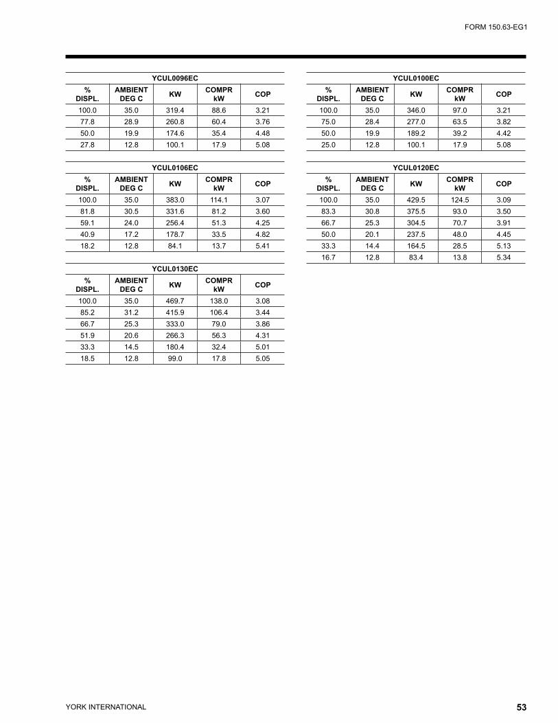
YORK INTERNATIONAL52 YORK INTERNATIONAL 53
FORM 150.63-EG1
YCUL0096EC%
DISPL.AMBIENT
DEG C KW COMPRkW COP
100.0 35.0 319.4 88.6 3.2177.8 28.9 260.8 60.4 3.7650.0 19.9 174.6 35.4 4.4827.8 12.8 100.1 17.9 5.08
YCUL0106EC%
DISPL.AMBIENT
DEG C KW COMPRkW COP
100.0 35.0 383.0 114.1 3.0781.8 30.5 331.6 81.2 3.6059.1 24.0 256.4 51.3 4.2540.9 17.2 178.7 33.5 4.8218.2 12.8 84.1 13.7 5.41
YCUL0130EC%
DISPL.AMBIENT
DEG C KW COMPRkW COP
100.0 35.0 469.7 138.0 3.0885.2 31.2 415.9 106.4 3.4466.7 25.3 333.0 79.0 3.8651.9 20.6 266.3 56.3 4.3133.3 14.5 180.4 32.4 5.0118.5 12.8 99.0 17.8 5.05
YCUL0100EC%
DISPL.AMBIENT
DEG C KW COMPRkW COP
100.0 35.0 346.0 97.0 3.2175.0 28.4 277.0 63.5 3.8250.0 19.9 189.2 39.2 4.4225.0 12.8 100.1 17.9 5.08
YCUL0120EC%
DISPL.AMBIENT
DEG C KW COMPRkW COP
100.0 35.0 429.5 124.5 3.0983.3 30.8 375.5 93.0 3.5066.7 25.3 304.5 70.7 3.9150.0 20.1 237.5 48.0 4.4533.3 14.4 164.5 28.5 5.1316.7 12.8 83.4 13.8 5.34
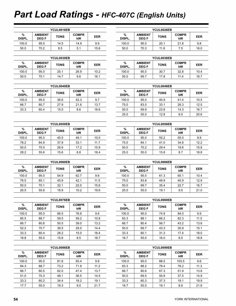
YORK INTERNATIONAL54 YORK INTERNATIONAL 55
FORM 150.63-EG1Part Load Ratings - HFC-407C (English Units)
YCUL0016EB%
DISPL.AMBIENT
DEG F TONS COMPRkW EER
100.0 95.0 14.5 14.9 9.950.0 70.2 8.5 5.1 15.6
YCUL0030EB%
DISPL.AMBIENT
DEG F TONS COMPRkW EER
100.0 95.0 25.1 26.9 10.250.0 70.1 14.7 9.6 16.1
YCUL0040EB%
DISPL.AMBIENT
DEG F TONS COMPRkW EER
100.0 95.0 36.6 42.3 9.766.7 80.7 27.9 21.6 13.733.3 60.4 15.5 8.6 18.6
YCUL0050EB%
DISPL.AMBIENT
DEG F TONS COMPRkW EER
100.0 95.0 45.5 49.1 10.078.2 84.9 37.9 33.1 11.750.0 70.0 26.6 17.2 15.928.2 55.6 15.6 8.8 18.4
YCUL0060EB%
DISPL.AMBIENT
DEG F TONS COMPRkW EER
100.0 95.0 54.9 62.7 9.676.5 85.1 45.9 42.1 11.550.0 70.1 32.1 22.0 15.626.5 55.6 18.9 10.2 19.6
YCUL0076EB%
DISPL.AMBIENT
DEG F TONS COMPRkW EER
100.0 95.0 66.5 76.8 9.685.5 88.7 59.5 59.2 10.866.7 80.6 50.5 39.0 13.252.2 70.7 39.5 29.5 14.433.3 60.4 28.2 15.0 18.418.8 55.0 15.8 8.5 18.7
YCUL0086EB%
DISPL.AMBIENT
DEG F TONS COMPRkW EER
100.0 95.0 81.8 93.4 9.884.3 88.7 73.2 71.9 11.266.7 80.5 62.0 47.4 13.751.0 70.3 48.1 36.5 14.533.3 60.2 34.4 18.2 19.117.7 55.0 19.3 9.0 21.7
YCUL0026EB%
DISPL.AMBIENT
DEG F TONS COMPRkW EER
100.0 95.0 20.1 21.8 9.850.0 70.3 11.8 7.5 16.0
YCUL0036EB%
DISPL.AMBIENT
DEG F TONS COMPRkW EER
100.0 95.0 30.7 32.8 10.450.0 69.7 17.8 11.4 16.7
YCUL0046EB%
DISPL.AMBIENT
DEG F TONS COMPRkW EER
100.0 95.0 40.9 41.4 10.575.0 83.5 33.1 26.3 12.550.0 69.9 23.8 14.3 16.725.0 55.0 12.8 6.0 20.6
YCUL0056EB%
DISPL.AMBIENT
DEG F TONS COMPRkW EER
100.0 95.0 50.2 55.0 9.975.0 84.1 41.0 34.8 12.250.0 70.2 29.4 19.6 15.825.0 55.0 15.8 8.7 18.8
YCUL0066EB%
DISPL.AMBIENT
DEG F TONS COMPRkW EER
100.0 95.0 61.3 65.1 10.475.0 83.8 49.9 40.9 12.950.0 69.7 35.4 22.7 16.725.0 55.0 19.1 9.5 21.0
YCUL0080EB%
DISPL.AMBIENT
DEG F TONS COMPRkW EER
100.0 95.0 74.9 84.0 9.983.3 88.1 66.2 62.3 11.566.7 80.4 56.7 43.2 13.650.0 69.7 43.3 30.9 15.133.3 60.1 31.3 17.4 18.016.7 55.0 16.0 8.5 18.8
YCUL0090EB%
DISPL.AMBIENT
DEG F TONS COMPRkW EER
100.0 95.0 88.5 103.5 9.683.3 88.2 78.4 76.2 11.366.7 80.6 67.3 51.9 13.850.0 69.5 50.9 37.5 14.933.3 60.3 37.3 19.1 19.916.7 55.0 19.1 8.9 21.6

YORK INTERNATIONAL54 YORK INTERNATIONAL 55
FORM 150.63-EG1
YCUL0096EB%
DISPL.AMBIENT
DEG F TONS COMPRkW EER
100.0 95.0 87.2 90.4 10.377.8 84.5 71.9 61.3 12.350.0 68.7 49.0 34.5 15.427.8 55.0 28.2 16.2 18.9
YCUL0106EB%
DISPL.AMBIENT
DEG F TONS COMPRkW EER
100.0 95.0 104.2 116.0 9.981.8 87.5 91.2 82.8 11.759.1 76.2 71.5 50.9 14.340.9 64.0 50.3 32.0 17.018.2 55.0 24.1 12.7 19.9
YCUL0130EB%
DISPL.AMBIENT
DEG F TONS COMPRkW EER
100.0 95.0 128.0 140.4 9.985.2 88.5 114.2 108.6 11.166.7 78.3 92.5 79.3 12.851.9 69.8 74.3 55.6 14.633.3 58.9 51.1 30.2 18.118.5 55.0 28.1 15.8 19.1
YCUL0100EB%
DISPL.AMBIENT
DEG F TONS COMPRkW EER
100.0 95.0 94.2 99.5 10.275.0 83.5 76.1 64.3 12.550.0 68.5 52.6 38.2 15.125.0 55.0 28.2 16.2 18.9
YCUL0120EB%
DISPL.AMBIENT
DEG F TONS COMPRkW EER
100.0 95.0 117.6 125.8 10.183.3 88.0 103.9 94.1 11.566.7 78.6 85.4 70.3 13.250.0 69.3 67.2 47.1 15.433.3 58.9 46.9 26.9 18.416.7 55.0 23.9 12.8 19.6
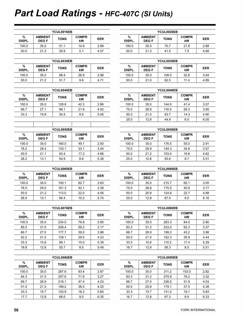
YORK INTERNATIONAL56 YORK INTERNATIONAL 57
FORM 150.63-EG1Part Load Ratings - HFC-407C (SI Units)
YCUL0016EB%
DISPL.AMBIENT
DEG F TONS COMPRkW EER
100.0 35.0 51.1 14.9 2.8950.0 21.2 29.9 5.1 4.57
YCUL0030EB%
DISPL.AMBIENT
DEG F TONS COMPRkW EER
100.0 35.0 88.4 26.9 2.9850.0 21.2 51.7 9.6 4.71
YCUL0040EB%
DISPL.AMBIENT
DEG F TONS COMPRkW EER
100.0 35.0 128.8 42.3 2.8666.7 27.1 98.1 21.6 4.0233.3 15.8 54.5 8.6 5.45
YCUL0050EB%
DISPL.AMBIENT
DEG F TONS COMPRkW EER
100.0 35.0 160.0 49.1 2.9378.2 29.4 133.1 33.1 3.4450.0 21.1 93.4 17.2 4.6628.2 13.1 54.9 8.8 5.38
YCUL0060EB%
DISPL.AMBIENT
DEG F TONS COMPRkW EER
100.0 35.0 193.1 62.7 2.8376.5 29.5 161.3 42.1 3.3850.0 21.2 113.0 22.0 4.5626.5 13.1 66.4 10.2 5.74
YCUL0076EB%
DISPL.AMBIENT
DEG F TONS COMPRkW EER
100.0 35.0 234.0 76.8 2.8085.5 31.5 209.4 59.2 3.1766.7 27.0 177.7 39.0 3.8852.2 21.5 139.1 29.5 4.2333.3 15.8 99.1 15.0 5.3918.8 12.8 55.7 8.5 5.48
YCUL0086EB%
DISPL.AMBIENT
DEG F TONS COMPRkW EER
100.0 35.0 287.6 93.4 2.8784.3 31.5 257.6 71.9 3.2766.7 26.9 218.1 47.4 4.0351.0 21.3 169.2 36.5 4.2533.3 15.7 120.9 18.2 5.6017.7 12.8 68.0 9.0 6.35
YCUL0026EB%
DISPL.AMBIENT
DEG F TONS COMPRkW EER
100.0 35.0 70.7 21.8 2.8850.0 21.3 41.5 7.5 4.68
YCUL0036EB%
DISPL.AMBIENT
DEG F TONS COMPRkW EER
100.0 35.0 108.0 32.8 3.0450.0 21.0 62.5 11.4 4.89
YCUL0046EB%
DISPL.AMBIENT
DEG F TONS COMPRkW EER
100.0 35.0 144.0 41.4 3.0775.0 28.6 116.5 26.3 3.6550.0 21.0 83.7 14.3 4.9025.0 12.8 44.9 6.0 6.05
YCUL0056EB%
DISPL.AMBIENT
DEG F TONS COMPRkW EER
100.0 35.0 176.5 55.0 2.9175.0 28.9 144.3 34.8 3.5750.0 21.2 103.4 19.6 4.6225.0 12.8 55.6 8.7 5.51
YCUL0066EB%
DISPL.AMBIENT
DEG F TONS COMPRkW EER
100.0 35.0 215.7 65.1 3.0575.0 28.8 175.5 40.9 3.7750.0 20.9 124.6 22.7 4.8825.0 12.8 67.0 9.5 6.16
YCUL0080EB%
DISPL.AMBIENT
DEG F TONS COMPRkW EER
100.0 35.0 263.3 84.0 2.9083.3 31.2 233.0 62.3 3.3766.7 26.9 199.2 43.2 3.9850.0 21.0 152.3 30.9 4.4433.3 15.6 110.2 17.4 5.2916.7 12.8 56.3 8.5 5.51
YCUL0090EB%
DISPL.AMBIENT
DEG F TONS COMPRkW EER
100.0 35.0 311.2 103.5 2.8283.3 31.2 275.9 76.2 3.3266.7 27.0 236.5 51.9 4.0350.0 20.8 179.1 37.5 4.3833.3 15.7 131.2 19.1 5.8316.7 12.8 67.3 8.9 6.33
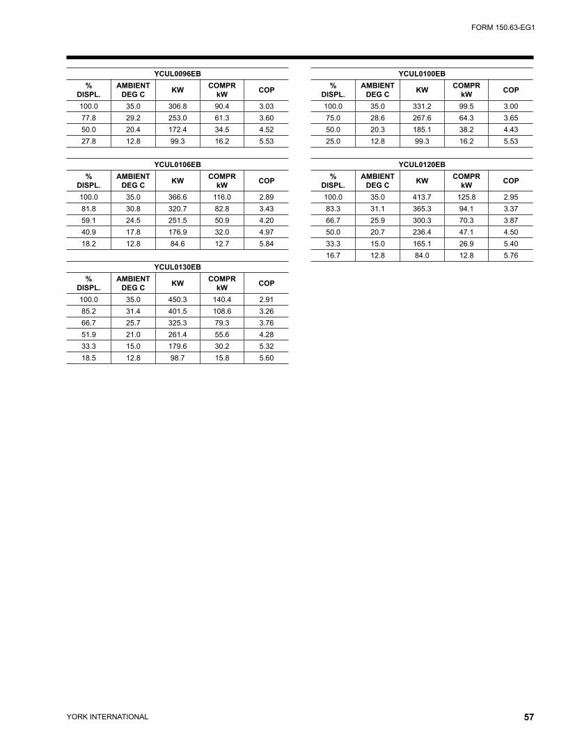
YORK INTERNATIONAL56 YORK INTERNATIONAL 57
FORM 150.63-EG1
YCUL0096EB%
DISPL.AMBIENT
DEG C KW COMPRkW COP
100.0 35.0 306.8 90.4 3.0377.8 29.2 253.0 61.3 3.6050.0 20.4 172.4 34.5 4.5227.8 12.8 99.3 16.2 5.53
YCUL0106EB%
DISPL.AMBIENT
DEG C KW COMPRkW COP
100.0 35.0 366.6 116.0 2.8981.8 30.8 320.7 82.8 3.4359.1 24.5 251.5 50.9 4.2040.9 17.8 176.9 32.0 4.9718.2 12.8 84.6 12.7 5.84
YCUL0130EB%
DISPL.AMBIENT
DEG C KW COMPRkW COP
100.0 35.0 450.3 140.4 2.9185.2 31.4 401.5 108.6 3.2666.7 25.7 325.3 79.3 3.7651.9 21.0 261.4 55.6 4.2833.3 15.0 179.6 30.2 5.3218.5 12.8 98.7 15.8 5.60
YCUL0100EB%
DISPL.AMBIENT
DEG C KW COMPRkW COP
100.0 35.0 331.2 99.5 3.0075.0 28.6 267.6 64.3 3.6550.0 20.3 185.1 38.2 4.4325.0 12.8 99.3 16.2 5.53
YCUL0120EB%
DISPL.AMBIENT
DEG C KW COMPRkW COP
100.0 35.0 413.7 125.8 2.9583.3 31.1 365.3 94.1 3.3766.7 25.9 300.3 70.3 3.8750.0 20.7 236.4 47.1 4.5033.3 15.0 165.1 26.9 5.4016.7 12.8 84.0 12.8 5.76
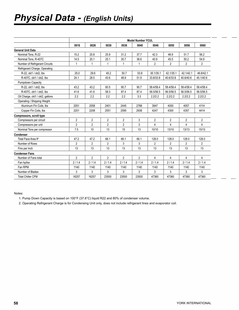
YORK INTERNATIONAL58 YORK INTERNATIONAL 59
FORM 150.63-EG1
Physical Data - (English Units)
Notes: 1. Pump Down Capacity is based on 100°F (37.8°C) liquid R22 and 80% of condenser volume. 2. Operating Refrigerant Charge is for Condensing Unit only, does not include refrigerant lines and evaporator coil.
Model Number YCUL0016 0026 0030 0036 0040 0046 0050 0056 0060
General Unit DataNominal Tons, R-22 15.2 20.8 25.9 31.2 37.7 42.3 46.9 51.7 56.2Nominal Tons, R-407C 14.5 20.1 25.1 30.7 36.6 40.9 45.5 50.2 54.9Number of Refrigerant Circuits 1 1 1 1 1 2 2 2 2Refrigerant Charge, Operating
R-22, ckt1 / ckt2, lbs 25.0 29.6 45.2 50.7 53.8 35.1/35.1 42.1/35.1 42.1/42.1 46.8/42.1R-407C, ckt1 / ckt2, lbs 24.1 28.5 43.6 48.9 51.9 33.8/33.8 40.6/33.8 40.6/40.6 45.1/40.6
Pumpdown CapacityR-22, ckt1 / ckt2, lbs 43.2 43.2 60.5 90.7 90.7 58.4/58.4 58.4/58.4 58.4/58.4 58.4/58.4R-407C, ckt1 / ckt2, lbs 41.6 41.6 58.3 87.4 87.4 56.5/56.5 56.5/56.5 56.5/56.5 56.5/56.5
Oil Charge, ckt1 / ckt2, gallons 2.2 2.2 2.2 2.2 3.3 2.2/2.2 2.2/2.2 2.2/2.2 2.2/2.2Operating / Shipping Weight
Aluminum Fin Coils, lbs 2051 2058 2401 2445 2788 3947 4000 4057 4114Copper Fin Coils, lbs 2201 2208 2551 2595 2938 4247 4300 4357 4414
Compressors, scroll typeCompressors per circuit 2 2 2 2 3 2 2 2 2Compressors per unit 2 2 2 2 3 4 4 4 4Nominal Tons per compressor 7.5 10 13 15 13 10/10 13/10 13/13 15/13
CondenserTotal Face Area ft2 47.2 47.2 66.1 66.1 66.1 128.0 128.0 128.0 128.0Number of Rows 2 2 2 3 3 2 2 2 2Fins per Inch 13 13 13 13 13 13 13 13 13
Condenser FansNumber of Fans total 2 2 2 2 2 4 4 4 4Fan hp/kw 2 / 1.4 2 / 1.4 2 / 1.4 2 / 1.4 2 / 1.4 2 / 1.4 2 / 1.4 2 / 1.4 2 / 1.4Fan RPM 1140 1140 1140 1140 1140 1140 1140 1140 1140Number of Blades 3 3 3 3 3 3 3 3 3Total Chiller CFM 16257 16257 23500 23500 23500 47360 47360 47360 47360

YORK INTERNATIONAL58 YORK INTERNATIONAL 59
FORM 150.63-EG1
Model Number YCUL0066 0076 0080 0086 0090 0096 0100 0106 0120 0130
62.2 68.9 77.0 83.6 90.1 90.8 98.4 108.9 122.1 133.661.3 66.5 74.9 81.8 88.5 87.2 94.2 104.2 117.6 128.0
2 2 2 2 2 2 2 2 2 2
56.2/56.2 58.5/48.4 64.7/64.7 71.8/64.7 78.0/78.0 86.3/73.2 86.3/86.3 104.3/86.3 106.9/106.9 126.0/106.954.2/54.2 56.4/46.7 62.4/62.4 69.2/62.4 75.2/75.2 83.2/70.5 83.2/83.2 100.5/83.2 103.0/103.0 121.4/103.0
87.6/87.6 68.1/68.1 102.2/102.2 102.2/102.2 102.2/102.2 150.0/150.0 150.0/150.0 170.2/170.2 194.8/194.8 194.8/194.884.4/84.4 65.6/65.6 98.5/98.5 98.5/98.5 98.5/98.5 145.8/145.8 145.8/145.8 165.5/165.5 189.4/189.4 189.4/189.4
2.2/2.2 3.3/3.3 3.3/3.3 3.3/3.3 3.3/3.3 4.2/4.2 4.2/4.2 6.3/4.2 6.3/6.3 6.3/6.3
4175 4842 5004 5150 5240 5532 5646 6362 7744 77704475 5142 5384 5530 5620 6394 6474 7305 9012 9034
2 3 3 3 3 2 2 3/2 3 34 6 6 6 6 4 4 5 6 6
15/15 13/10 13/13 15/13 15/15 25/20 25/25 20/25 20/20 25/20
128.0 149.3 149.3 149.3 149.3 168.0 168.0 192.0 222.0 222.03 2 3 3 3 3 3 3 3 3
13 13 13 13 13 13 13 13 13 13
4 4 4 4 4 6 6 6 8 82 / 1.4 2 / 1.4 2 / 1.7 2 / 1.7 2 / 1.7 2 / 1.8 2 / 1.8 2 / 1.8 2 / 1.8 2 / 1.81140 1140 1140 1140 1140 1140 1140 1140 1140 1140
3 3 3 3 3 3 3 3 3 347360 46080 55253 55253 54550 79800 79800 85800 106400 106400
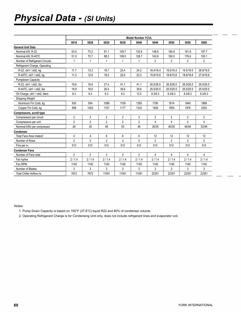
YORK INTERNATIONAL60 YORK INTERNATIONAL 61
FORM 150.63-EG1
Physical Data - (SI Units)
Notes: 1. Pump Down Capacity is based on 100°F (37.8°C) liquid R22 and 80% of condenser volume. 2. Operating Refrigerant Charge is for Condensing Unit only, does not include refrigerant lines and evaporator coil.
Model Number YCUL0016 0026 0030 0036 0040 0046 0050 0056 0060
General Unit DataNominal kW, R-22 53.5 73.2 91.1 109.7 132.6 148.8 164.9 181.8 197.7Nominal kW, R-407C 51.0 70.7 88.3 108.0 128.7 143.8 160.0 176.6 193.1Number of Refrigerant Circuits 1 1 1 1 1 2 2 2 2Refrigerant Charge, Operating
R-22, ckt1 / ckt2, kg 11.7 13.3 18.7 23.4 24.2 16.4/16.4 19.5/16.4 19.5/19.5 28.9/19.5R-407C, ckt1 / ckt2, kg 11.3 12.8 18.0 22.6 23.3 15.8/15.8 18.8/15.8 18.8/18.8 27.9/18.8
Pumpdown CapacityR-22, ckt1 / ckt2, lbs 19.6 19.6 27.4 41.1 41.1 26.5/26.5 26.5/26.5 26.5/26.5 26.5/26.5R-407C, ckt1 / ckt2, lbs 18.9 18.9 26.4 39.6 39.6 25.5/25.5 25.5/25.5 25.5/25.5 25.5/25.5
Oil Charge, ckt1 / ckt2, liters 8.3 8.3 8.3 8.3 12.5 8.3/8.3 8.3/8.3 8.3/8.3 8.3/8.3Shipping Weight
Aluminum Fin Coils, kg 930 934 1089 1109 1265 1790 1814 1840 1866Copper Fin Coils, kg 998 1002 1157 1177 1333 1926 1950 1976 2002
Compressors, scroll typeCompressors per circuit 2 2 2 2 3 2 2 2 2Compressors per unit 2 2 2 2 3 4 4 4 4Nominal kWo per compressor 26 35 46 53 46 35/35 46/35 46/46 53/46
CondenserTotal Face Area meters2 4 4 6 6 6 12 12 12 12Number of Rows 2 2 2 3 3 2 2 2 2Fins per m 512 512 512 512 512 512 512 512 512
Condenser FansNumber of Fans total 2 2 2 2 2 4 4 4 4Fan hp/kw 2 / 1.4 2 / 1.4 2 / 1.4 2 / 1.4 2 / 1.4 2 / 1.4 2 / 1.4 2 / 1.4 2 / 1.4Fan RPM 1140 1140 1140 1140 1140 1140 1140 1140 1140Number of Blades 3 3 3 3 3 3 3 3 3Total Chiller Airflow l/s 7672 7672 11091 11091 11091 22351 22351 22351 22351
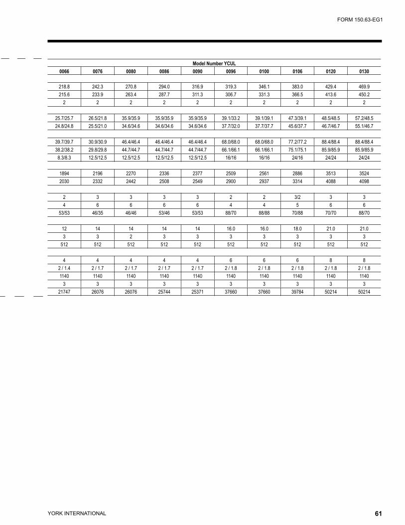
YORK INTERNATIONAL60 YORK INTERNATIONAL 61
FORM 150.63-EG1
Model Number YCUL0066 0076 0080 0086 0090 0096 0100 0106 0120 0130
218.8 242.3 270.8 294.0 316.9 319.3 346.1 383.0 429.4 469.9215.6 233.9 263.4 287.7 311.3 306.7 331.3 366.5 413.6 450.2
2 2 2 2 2 2 2 2 2 2
25.7/25.7 26.5/21.8 35.9/35.9 35.9/35.9 35.9/35.9 39.1/33.2 39.1/39.1 47.3/39.1 48.5/48.5 57.2/48.524.8/24.8 25.5/21.0 34.6/34.6 34.6/34.6 34.6/34.6 37.7/32.0 37.7/37.7 45.6/37.7 46.7/46.7 55.1/46.7
39.7/39.7 30.9/30.9 46.4/46.4 46.4/46.4 46.4/46.4 68.0/68.0 68.0/68.0 77.2/77.2 88.4/88.4 88.4/88.438.2/38.2 29.8/29.8 44.7/44.7 44.7/44.7 44.7/44.7 66.1/66.1 66.1/66.1 75.1/75.1 85.9/85.9 85.9/85.9
8.3/8.3 12.5/12.5 12.5/12.5 12.5/12.5 12.5/12.5 16/16 16/16 24/16 24/24 24/24
1894 2196 2270 2336 2377 2509 2561 2886 3513 35242030 2332 2442 2508 2549 2900 2937 3314 4088 4098
2 3 3 3 3 2 2 3/2 3 34 6 6 6 6 4 4 5 6 6
53/53 46/35 46/46 53/46 53/53 88/70 88/88 70/88 70/70 88/70
12 14 14 14 14 16.0 16.0 18.0 21.0 21.03 3 2 3 3 3 3 3 3 3
512 512 512 512 512 512 512 512 512 512
4 4 4 4 4 6 6 6 8 82 / 1.4 2 / 1.7 2 / 1.7 2 / 1.7 2 / 1.7 2 / 1.8 2 / 1.8 2 / 1.8 2 / 1.8 2 / 1.81140 1140 1140 1140 1140 1140 1140 1140 1140 1140
3 3 3 3 3 3 3 3 3 321747 26076 26076 25744 25371 37660 37660 39784 50214 50214
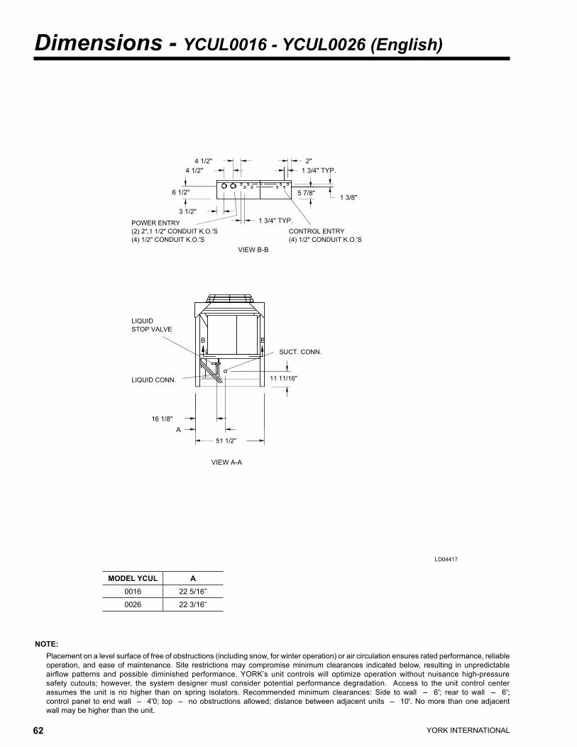
YORK INTERNATIONAL62 YORK INTERNATIONAL 63
FORM 150.63-EG1
��������
���������������������������� �������������
��������
����������������������� �����������������������
����������� �����������
�����������
�������
������
������
������
������
������������
��
� �
���������
�����������
����������
������
�
�������
������������
Dimensions - YCUL0016 - YCUL0026 (English)
NOTE: Placement on a level surface of free of obstructions (including snow, for winter operation) or air circulation ensures rated performance, reliable
operation, and ease of maintenance. Site restrictions may compromise minimum clearances indicated below, resulting in unpredictable airflow patterns and possible diminished performance. YORK’s unit controls will optimize operation without nuisance high-pressure safety cutouts; however, the system designer must consider potential performance degradation. Access to the unit control center assumes the unit is no higher than on spring isolators. Recommended minimum clearances: Side to wall – 6'; rear to wall – 6'; control panel to end wall – 4'0; top – no obstructions allowed; distance between adjacent units – 10'. No more than one adjacent wall may be higher than the unit.
LD04417
MODEL YCUL A0016 22 5/16”
0026 22 3/16”
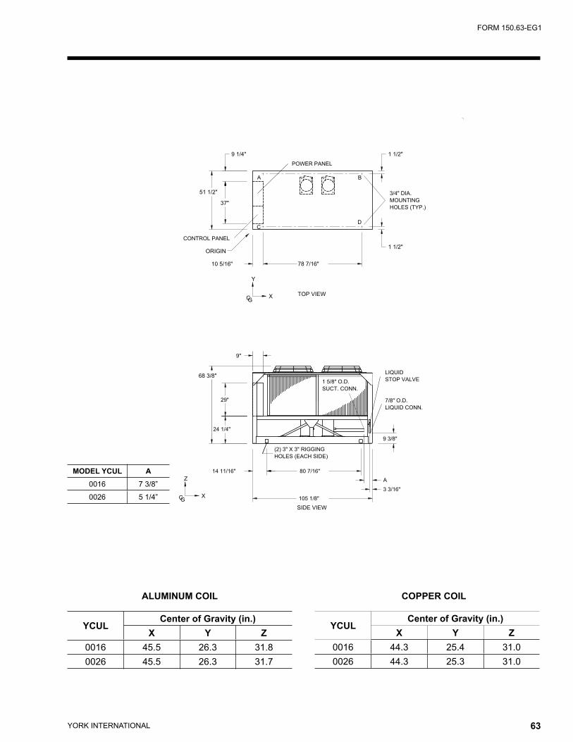
YORK INTERNATIONAL62 YORK INTERNATIONAL 63
FORM 150.63-EG1
YCULCenter of Gravity (in.)
X Y Z0016 45.5 26.3 31.80026 45.5 26.3 31.7
ALUMINUM COIL COPPER COIL
YCULCenter of Gravity (in.)
X Y Z0016 44.3 25.4 31.00026 44.3 25.3 31.0
MODEL YCUL A0016 7 3/8”
0026 5 1/4”
������������
��������
���������
��������
�������������������
�����������������
���������
�����������
�������������
������
�
���
��
�
� ��������
���
�������
��
������
�������
������
������
�������
���
������
����������
�����������
�����������
��������� ��������
�������
�
������
���������
������������
�
�������� ��������
�
� �
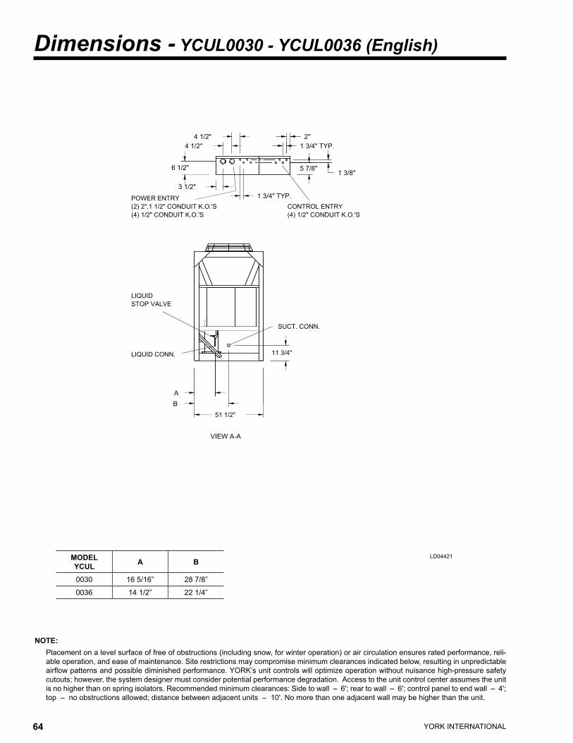
YORK INTERNATIONAL64 YORK INTERNATIONAL 65
FORM 150.63-EG1
Dimensions - YCUL0030 - YCUL0036 (English)
NOTE: Placement on a level surface of free of obstructions (including snow, for winter operation) or air circulation ensures rated performance, reli-
able operation, and ease of maintenance. Site restrictions may compromise minimum clearances indicated below, resulting in unpredictable airflow patterns and possible diminished performance. YORK’s unit controls will optimize operation without nuisance high-pressure safety cutouts; however, the system designer must consider potential performance degradation. Access to the unit control center assumes the unit is no higher than on spring isolators. Recommended minimum clearances: Side to wall – 6'; rear to wall – 6'; control panel to end wall – 4'; top – no obstructions allowed; distance between adjacent units – 10'. No more than one adjacent wall may be higher than the unit.
LD04421
�������������
�����������������������
�����������
����������������������������
�����������������������
��������
�����������
�����������
�������
������������
������
��
������
������
������
�
�������
�����������
������
����������
������������
�
MODEL YCUL A B
0030 16 5/16” 28 7/8”
0036 14 1/2” 22 1/4”
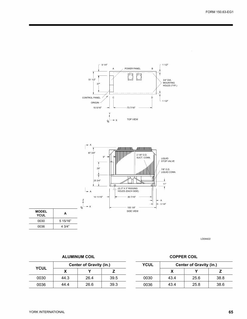
YORK INTERNATIONAL64 YORK INTERNATIONAL 65
FORM 150.63-EG1
LD04422
������������
��������
���������
��������
�������������������
�����������������
���������
�����������
�������������
������
�
���
�
�
��
�
� ��������
�����������������
���
�������
��
���
�������
������
������
�������
������
�
�����������
�����������
���
������
����������
���������
������������
�
�������� ��������
�
� �
������
ALUMINUM COIL COPPER COIL
YCULCenter of Gravity (in.)
X Y Z0030 44.3 26.4 39.50036 44.4 26.6 39.3
YCUL Center of Gravity (in.)X Y Z
0030 43.4 25.6 38.80036 43.4 25.8 38.6
MODEL YCUL A
0030 5 15/16”
0036 4 3/4”
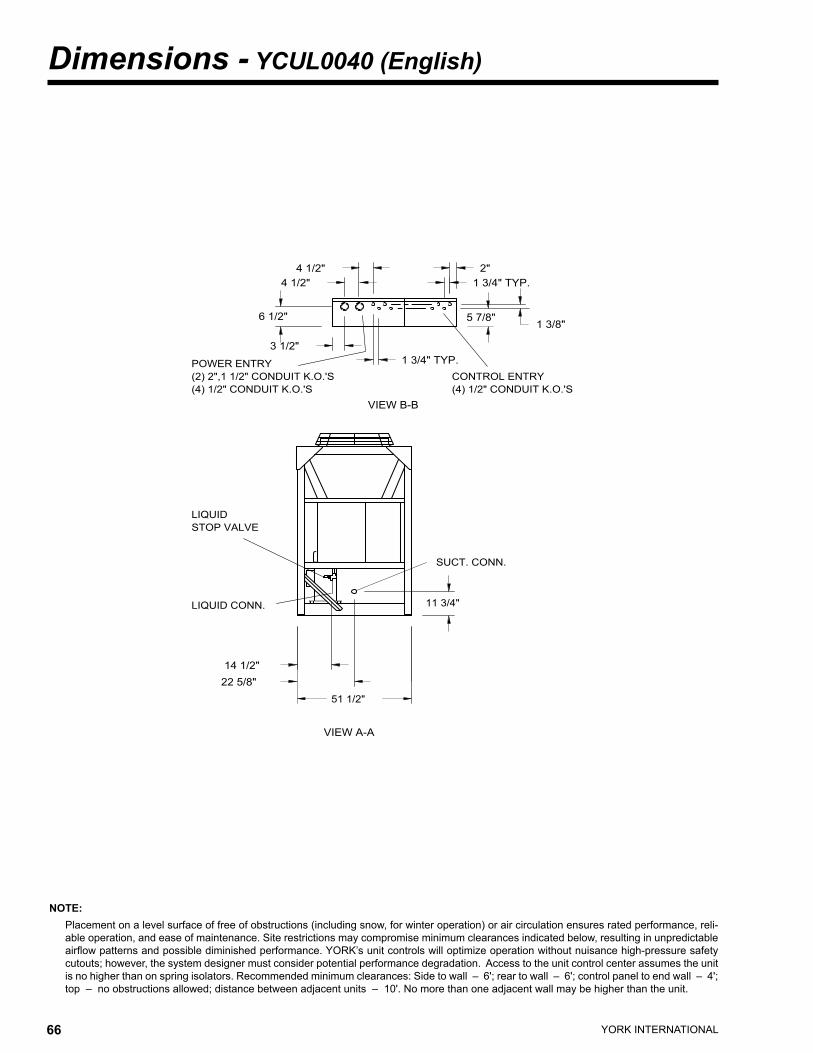
YORK INTERNATIONAL66 YORK INTERNATIONAL 67
FORM 150.63-EG1
NOTE: Placement on a level surface of free of obstructions (including snow, for winter operation) or air circulation ensures rated performance, reli-
able operation, and ease of maintenance. Site restrictions may compromise minimum clearances indicated below, resulting in unpredictable airflow patterns and possible diminished performance. YORK’s unit controls will optimize operation without nuisance high-pressure safety cutouts; however, the system designer must consider potential performance degradation. Access to the unit control center assumes the unit is no higher than on spring isolators. Recommended minimum clearances: Side to wall – 6'; rear to wall – 6'; control panel to end wall – 4'; top – no obstructions allowed; distance between adjacent units – 10'. No more than one adjacent wall may be higher than the unit.
Dimensions - YCUL0040 (English)
�������������
�����������������������
�����������
����������������������������
�����������������������
��������
��������
�����������
�����������
�������
������������
������
��
������
������
������
�������
�������
�����������
������
����������
������������
�������
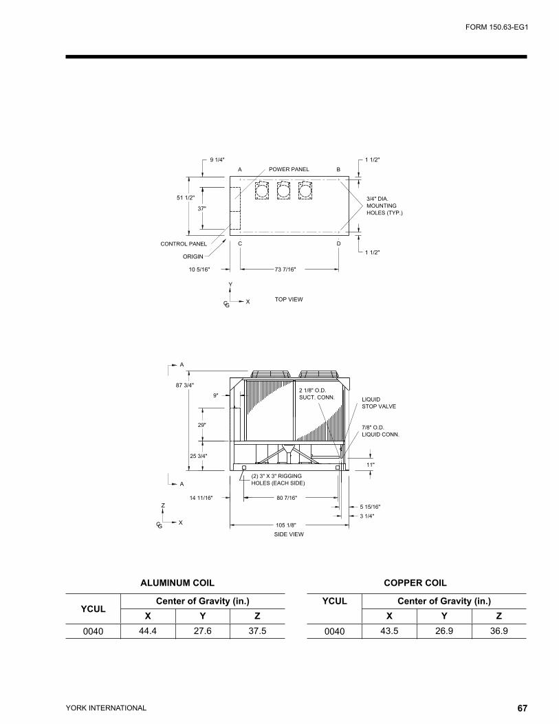
YORK INTERNATIONAL66 YORK INTERNATIONAL 67
FORM 150.63-EG1
ALUMINUM COIL COPPER COIL
YCULCenter of Gravity (in.)
X Y Z0040 44.4 27.6 37.5
YCUL Center of Gravity (in.)X Y Z
0040 43.5 26.9 36.9
������������
��������
���������
��������
�������������������
�����������������
���������
�����������
�������������
������
�
���
�
�
��
�
� ��������
�����������������
���
�������
��
���
�������
������
������
�������
������
��������
�����������
�����������
���
������
����������
���������
������������
�
�������� ��������
�
� �
������
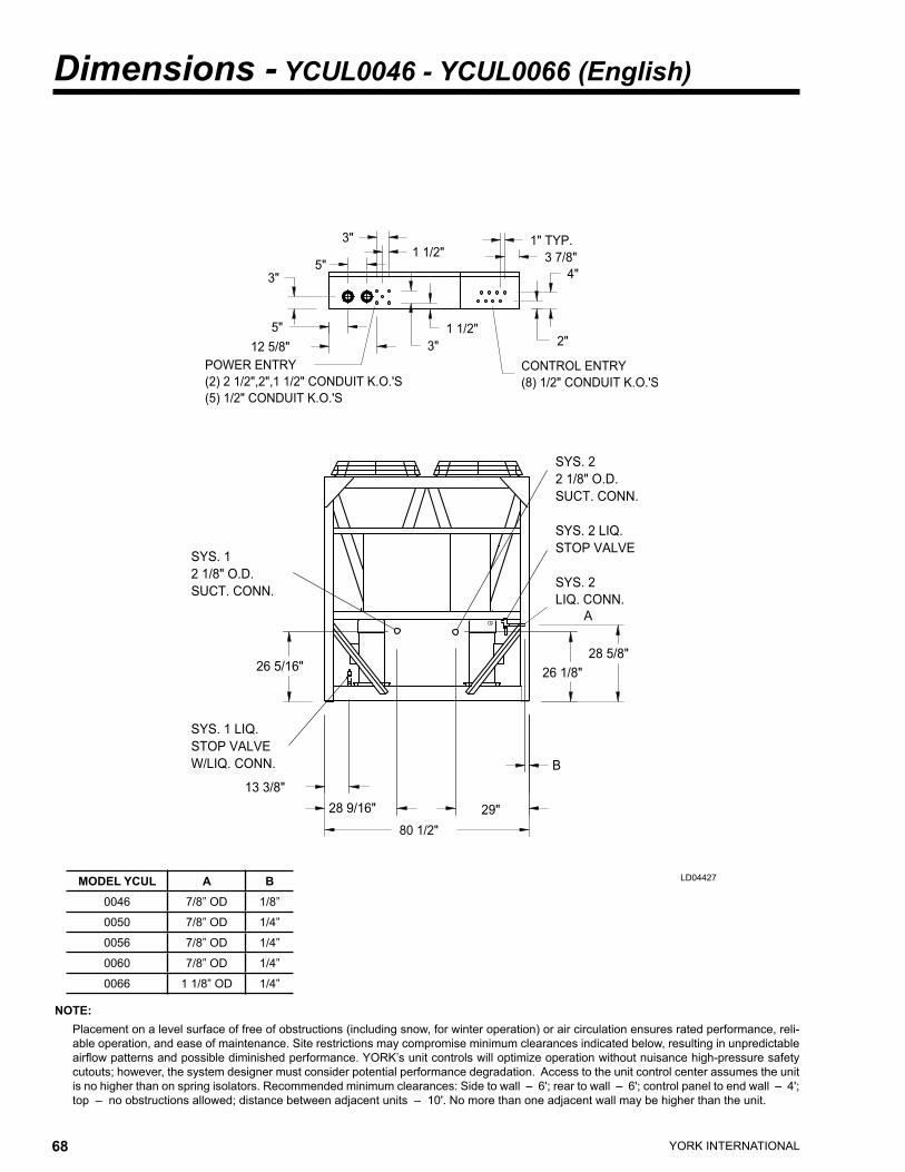
YORK INTERNATIONAL68 YORK INTERNATIONAL 69
FORM 150.63-EG1
Dimensions - YCUL0046 - YCUL0066 (English)
NOTE: Placement on a level surface of free of obstructions (including snow, for winter operation) or air circulation ensures rated performance, reli-
able operation, and ease of maintenance. Site restrictions may compromise minimum clearances indicated below, resulting in unpredictable airflow patterns and possible diminished performance. YORK’s unit controls will optimize operation without nuisance high-pressure safety cutouts; however, the system designer must consider potential performance degradation. Access to the unit control center assumes the unit is no higher than on spring isolators. Recommended minimum clearances: Side to wall – 6'; rear to wall – 6'; control panel to end wall – 4'; top – no obstructions allowed; distance between adjacent units – 10'. No more than one adjacent wall may be higher than the unit.
LD04427
����������������������������������� �����������������������
�����������������������
�������
�����������
������
�������������
���������
��
����
��
��
������
�������������
��
���
������
�����������
���������������
������
����������
���������
��������
�������
�
�������
�����������
����������
�����������
�����������
�����������
������
�����������
�����������
������������
MODEL YCUL A B0046 7/8” OD 1/8”
0050 7/8” OD 1/4”
0056 7/8” OD 1/4”
0060 7/8” OD 1/4”
0066 1 1/8” OD 1/4”
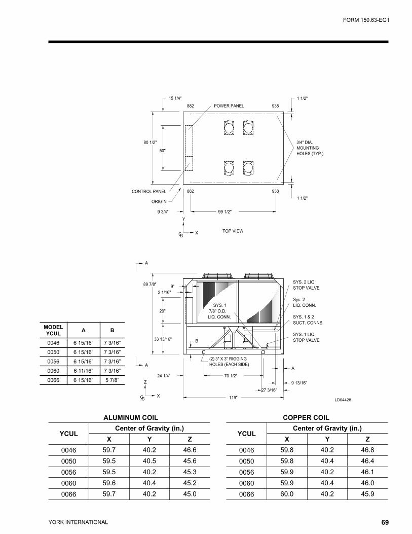
YORK INTERNATIONAL68 YORK INTERNATIONAL 69
FORM 150.63-EG1
�����������������
�������������������
���������
������������
��������
�������������
�����������
��������
������
���
�
�������
�
�������
����
���������
���
���������
�������
�
�������
���
������
������
�
����������
������������
������
���������
����������
������
�����������
����������
����������
��������
��������
�
�����������
�����������
���
������
�
���
�������
��� ���
���
�������
LD04428
ALUMINUM COIL COPPER COIL
YCULCenter of Gravity (in.)
X Y Z0046 59.7 40.2 46.60050 59.5 40.5 45.60056 59.5 40.2 45.30060 59.6 40.4 45.20066 59.7 40.2 45.0
YCULCenter of Gravity (in.)
X Y Z0046 59.8 40.2 46.80050 59.8 40.4 46.40056 59.9 40.2 46.10060 59.9 40.4 46.00066 60.0 40.2 45.9
MODEL YCUL A B
0046 6 15/16” 7 3/16”
0050 6 15/16” 7 3/16”
0056 6 15/16” 7 3/16”
0060 6 11/16” 7 3/16”
0066 6 15/16” 5 7/8”
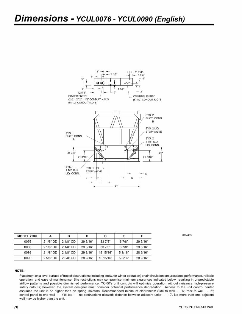
MODEL YCUL A B C D E F0076 2 1/8” OD 2 1/8” OD 29 3/16” 33 7/8” 6 7/8” 29 3/16”
0080 2 1/8” OD 2 1/8” OD 29 3/16” 33 7/8” 6 7/8” 29 3/16”
0086 2 1/8” OD 2 1/8” OD 29 3/16” 16 15/16” 5 3/16” 28 9/16”
0090 2 5/8” OD 2 5/8” OD 28 9/16” 16 15/16” 5 3/16” 28 9/16”
YORK INTERNATIONAL70 YORK INTERNATIONAL 71
FORM 150.63-EG1
Dimensions - YCUL0076 - YCUL0090 (English)
NOTE: Placement on a level surface of free of obstructions (including snow, for winter operation) or air circulation ensures rated performance, reliable
operation, and ease of maintenance. Site restrictions may compromise minimum clearances indicated below, resulting in unpredictable airflow patterns and possible diminished performance. YORK’s unit controls will optimize operation without nuisance high-pressure safety cutouts; however, the system designer must consider potential performance degradation. Access to the unit control center assumes the unit is no higher than on spring isolators. Recommended minimum clearances: Side to wall – 6'; rear to wall – 6'; control panel to end wall – 4'0; top – no obstructions allowed; distance between adjacent units – 10'. No more than one adjacent wall may be higher than the unit.
LD04435
����������
��������
������
�����������
�
���
��������
���������
��
��
��������
��
�������������
�����������������������
������
�������
�����������
�����������������������������������
�����������������������
��
������
�����������
����������
�����������
�����������
�������
���������
�
������
����������
�����������
����������
���
�����������
��������
�
�����������
�����������
������
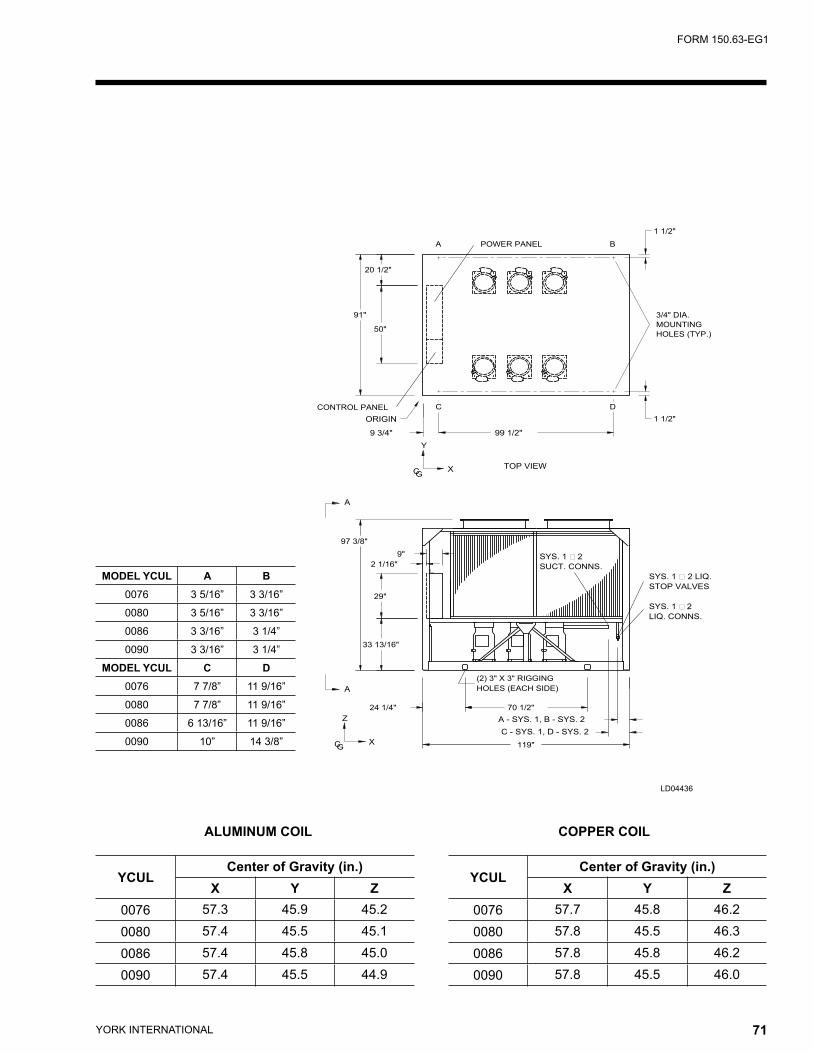
YORK INTERNATIONAL70 YORK INTERNATIONAL 71
FORM 150.63-EG1
LD04436
ALUMINUM COIL COPPER COIL
YCULCenter of Gravity (in.)
X Y Z0076 57.7 45.8 46.20080 57.8 45.5 46.30086 57.8 45.8 46.20090 57.8 45.5 46.0
YCULCenter of Gravity (in.)
X Y Z0076 57.3 45.9 45.20080 57.4 45.5 45.10086 57.4 45.8 45.00090 57.4 45.5 44.9
�������������������
���������
��������
������������
�����������������
�������������
��������
�����������
������
���
�������
���
�������
���
���������
������
������
��
�
�
�
�
�������
��
����������������������
�����������
������������
����������
����������
������� �������
����
����������������������
���������������
������������
�
������
��
�
�
�
�������
� �
MODEL YCUL A B0076 3 5/16” 3 3/16”
0080 3 5/16” 3 3/16”
0086 3 3/16” 3 1/4”
0090 3 3/16” 3 1/4”
MODEL YCUL C D0076 7 7/8” 11 9/16”
0080 7 7/8” 11 9/16”
0086 6 13/16” 11 9/16”
0090 10” 14 3/8”
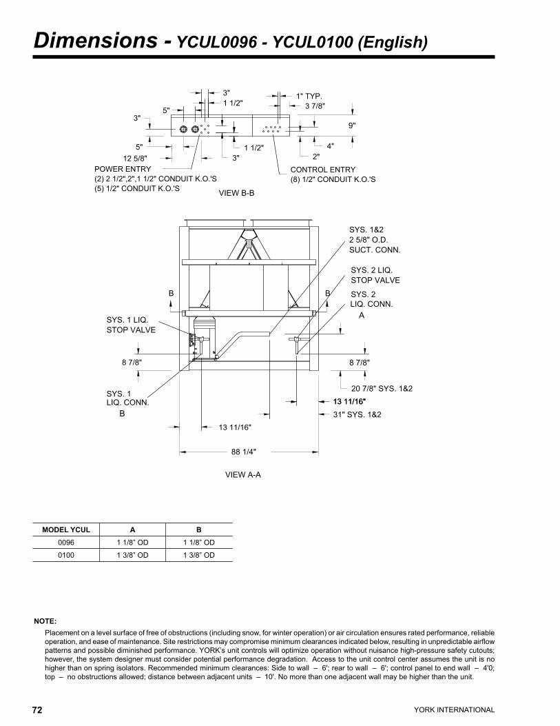
YORK INTERNATIONAL72 YORK INTERNATIONAL 73
FORM 150.63-EG1
NOTE: Placement on a level surface of free of obstructions (including snow, for winter operation) or air circulation ensures rated performance, reliable
operation, and ease of maintenance. Site restrictions may compromise minimum clearances indicated below, resulting in unpredictable airflow patterns and possible diminished performance. YORK’s unit controls will optimize operation without nuisance high-pressure safety cutouts; however, the system designer must consider potential performance degradation. Access to the unit control center assumes the unit is no higher than on spring isolators. Recommended minimum clearances: Side to wall – 6'; rear to wall – 6'; control panel to end wall – 4'0; top – no obstructions allowed; distance between adjacent units – 10'. No more than one adjacent wall may be higher than the unit.
Dimensions - YCUL0096 - YCUL0100 (English)
���������
������������
��
�����������������������
��
�����������������������������������
��
�����������
�������
��
������ ������
��
�������������
�����������������������
������
�������
��
��
��
��������
��������
�������
� �
�����������
�����������
������
����������������
����������������
������
���������
���������
��������
�����������
�����������
�����������
����������
������
����������
�
�
MODEL YCUL A B0096 1 1/8” OD 1 1/8” OD
0100 1 3/8” OD 1 3/8” OD
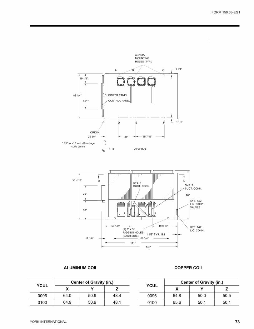
YORK INTERNATIONAL72 YORK INTERNATIONAL 73
FORM 150.63-EG1
ALUMINUM COIL COPPER COIL
YCULCenter of Gravity (in.)
X Y Z0096 64.0 50.9 48.40100 64.9 50.9 48.1
YCULCenter of Gravity (in.)
X Y Z0096 64.8 50.0 50.50100 65.6 50.1 50.1
�����
�������������
�����������
�����������
���������
������������
��������
��������
������
�������������
�����������
������� ��������
����
��������
���
�
����
���
�
���
�
������� ���
� �
� �
��������
�
�
�������
�������
���
�������
�����������
������
�����������
������
��������
���������
������
��������
����������
��������
����������������
������
������
������������������������������
�����������
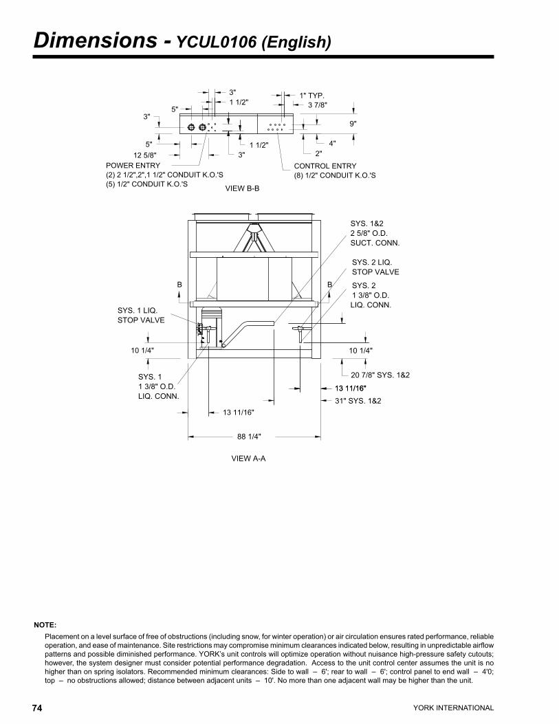
YORK INTERNATIONAL74 YORK INTERNATIONAL 75
FORM 150.63-EG1
NOTE: Placement on a level surface of free of obstructions (including snow, for winter operation) or air circulation ensures rated performance, reliable
operation, and ease of maintenance. Site restrictions may compromise minimum clearances indicated below, resulting in unpredictable airflow patterns and possible diminished performance. YORK’s unit controls will optimize operation without nuisance high-pressure safety cutouts; however, the system designer must consider potential performance degradation. Access to the unit control center assumes the unit is no higher than on spring isolators. Recommended minimum clearances: Side to wall – 6'; rear to wall – 6'; control panel to end wall – 4'0; top – no obstructions allowed; distance between adjacent units – 10'. No more than one adjacent wall may be higher than the unit.
Dimensions - YCUL0106 (English)
���������
������������
��
��������
��������
�����������������������
��
�����������������������������������
��
�����������
�������
��
������ ������
��
�������������
�����������������������
������
�������
��
��
��
�������
� �
�����������
�����������
�������
������
�����������
����������
����������������
�������
���������
���������
��������
�����������
�����������
�����������
����������
������
�����������
����������
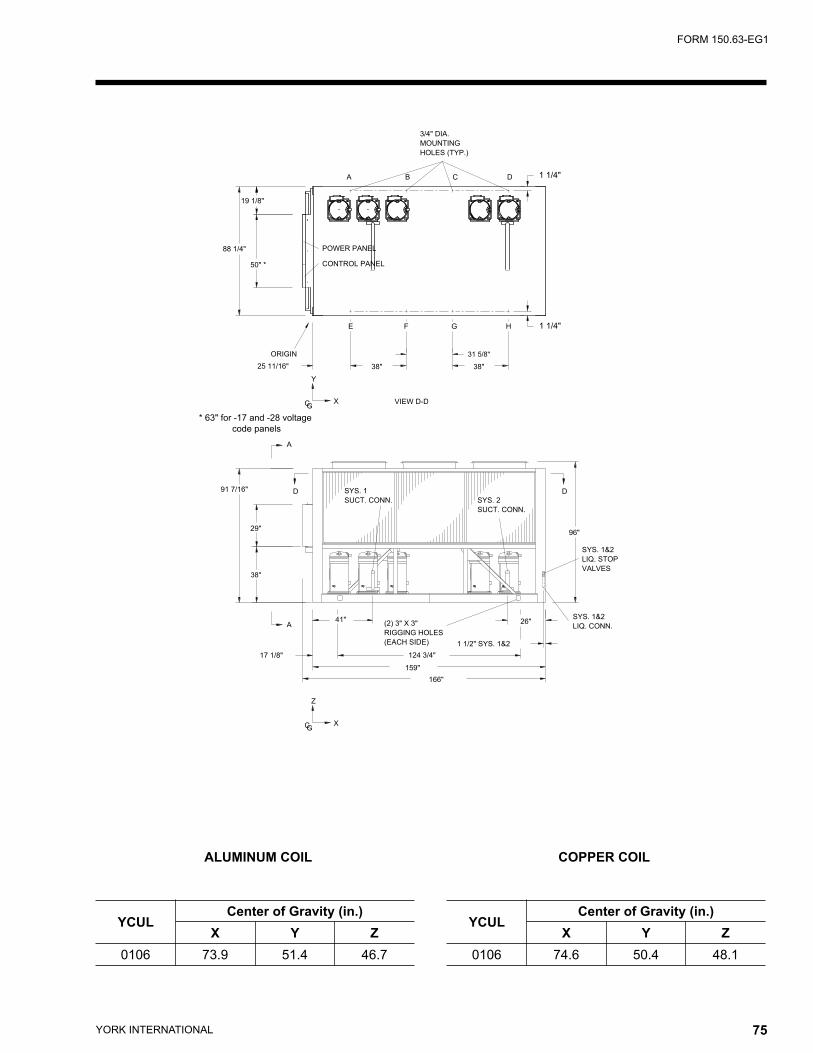
YORK INTERNATIONAL74 YORK INTERNATIONAL 75
FORM 150.63-EG1
ALUMINUM COIL COPPER COIL
YCULCenter of Gravity (in.)
X Y Z0106 73.9 51.4 46.7
YCULCenter of Gravity (in.)
X Y Z0106 74.6 50.4 48.1
�������������
�����������
�����������
���������
������������
��������
������
��������
�������������
�����������
������������������������������
�����������
�����
�������
���
�
����
����
��������
���
��������
�
�
�
���
�
�
�
���������
�������
���
�
�
�������
�
���
� ������
� ������
���
�
�
���
�������
���
�����������
������
�����������
������
��������
���������
������
��������
�������������
����������������
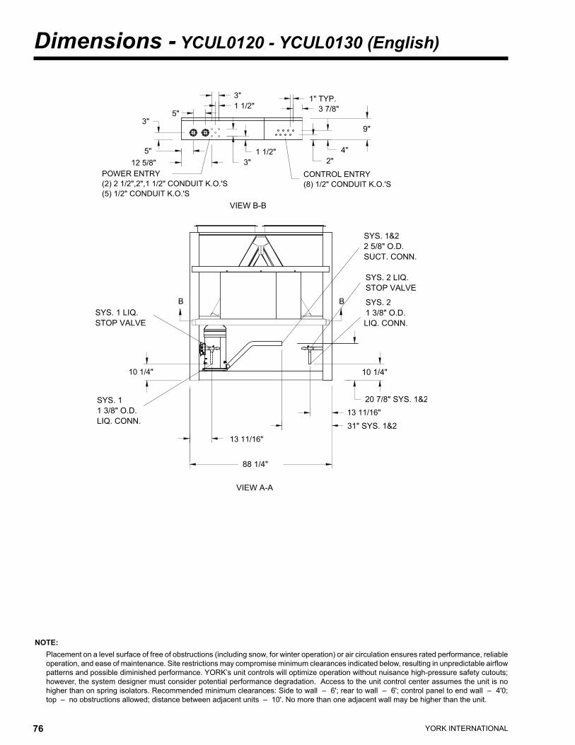
YORK INTERNATIONAL76 YORK INTERNATIONAL 77
FORM 150.63-EG1
NOTE: Placement on a level surface of free of obstructions (including snow, for winter operation) or air circulation ensures rated performance, reliable
operation, and ease of maintenance. Site restrictions may compromise minimum clearances indicated below, resulting in unpredictable airflow patterns and possible diminished performance. YORK’s unit controls will optimize operation without nuisance high-pressure safety cutouts; however, the system designer must consider potential performance degradation. Access to the unit control center assumes the unit is no higher than on spring isolators. Recommended minimum clearances: Side to wall – 6'; rear to wall – 6'; control panel to end wall – 4'0; top – no obstructions allowed; distance between adjacent units – 10'. No more than one adjacent wall may be higher than the unit.
Dimensions - YCUL0120 - YCUL0130 (English)
���������
������������
��
����������������������������������������������������������
�����������������������
������
�����������
��
��
�������
�������������
��
��������
��
�������
������
��
��
��������
��������
�������
� �
������
����������
�����������
�����������
�����������
��������
�����������
�����������
�����������
����������
������
�����������
����������
�������
����������������
���������
�������
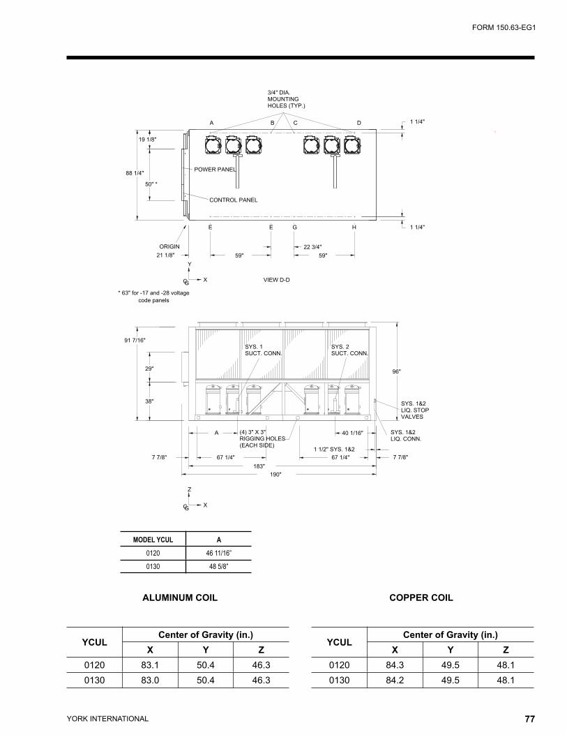
YORK INTERNATIONAL76 YORK INTERNATIONAL 77
FORM 150.63-EG1
ALUMINUM COIL COPPER COIL
YCULCenter of Gravity (in.)
X Y Z0120 84.3 49.5 48.10130 84.2 49.5 48.1
YCULCenter of Gravity (in.)
X Y Z0120 83.1 50.4 46.30130 83.0 50.4 46.3
MODEL YCUL A
0120 46 11/16”
0130 48 5/8”
�����
������
������������������������
��������
�����������
��������
�����������
�������������
������������
���������
�
�
��
������
��������
���
��
�������
�������
�������
����
�
����
�������
�
�
���
� � ������
� � � ������
���
������� ������
���
�
�
���
�������
�����������������
�����������������
���������������
��������
������������������
�������� ��������
����������������
������������������������������
�����������
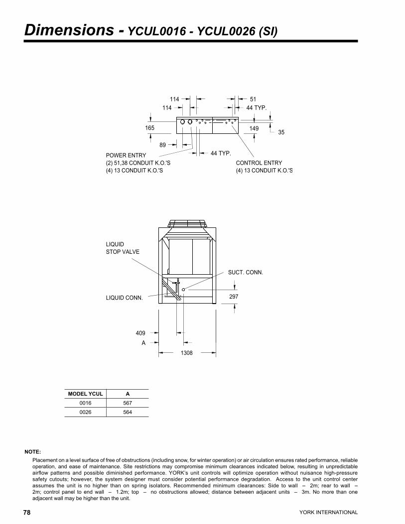
YORK INTERNATIONAL78 YORK INTERNATIONAL 79
FORM 150.63-EG1
NOTE: Placement on a level surface of free of obstructions (including snow, for winter operation) or air circulation ensures rated performance, reliable
operation, and ease of maintenance. Site restrictions may compromise minimum clearances indicated below, resulting in unpredictable airflow patterns and possible diminished performance. YORK’s unit controls will optimize operation without nuisance high-pressure safety cutouts; however, the system designer must consider potential performance degradation. Access to the unit control center assumes the unit is no higher than on spring isolators. Recommended minimum clearances: Side to wall – 2m; rear to wall – 2m; control panel to end wall – 1.2m; top – no obstructions allowed; distance between adjacent units – 3m. No more than one adjacent wall may be higher than the unit.
Dimensions - YCUL0016 - YCUL0026 (SI)
������������������������ �������������
��������������������� ���������������������
����������� �������
�������
����
���
��
���
���
�����
��
���
�����������
����������
������
�����
���
������������
MODEL YCUL A0016 567
0026 564
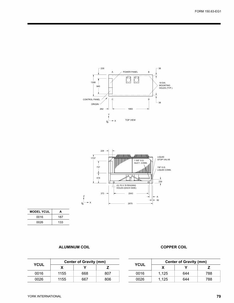
YORK INTERNATIONAL78 YORK INTERNATIONAL 79
FORM 150.63-EG1
ALUMINUM COIL COPPER COIL
YCULCenter of Gravity (mm)
X Y Z0016 1155 668 8070026 1155 667 806
YCULCenter of Gravity (mm)
X Y Z0016 1,125 644 7880026 1,125 644 788
������������
��������
�������
��������
�������������������
�����������������
�����������
�������������
������
�
���
��
�
� ����
���
���
���
���
����
��
��
����
���
������
����������
�����������
�����������
��� ����
��
�
���
���������
������������
�
��� ����
�
� �
MODEL YCUL A0016 187
0026 133
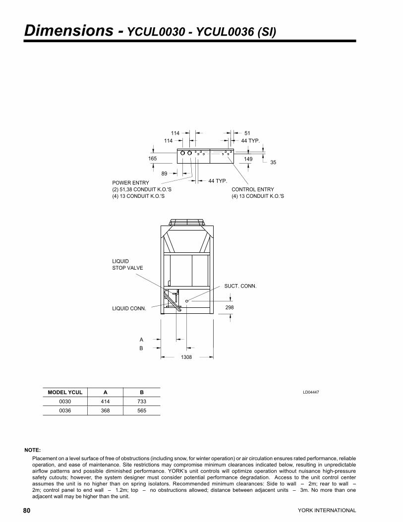
YORK INTERNATIONAL80 YORK INTERNATIONAL 81
FORM 150.63-EG1
NOTE: Placement on a level surface of free of obstructions (including snow, for winter operation) or air circulation ensures rated performance, reliable
operation, and ease of maintenance. Site restrictions may compromise minimum clearances indicated below, resulting in unpredictable airflow patterns and possible diminished performance. YORK’s unit controls will optimize operation without nuisance high-pressure safety cutouts; however, the system designer must consider potential performance degradation. Access to the unit control center assumes the unit is no higher than on spring isolators. Recommended minimum clearances: Side to wall – 2m; rear to wall – 2m; control panel to end wall – 1.2m; top – no obstructions allowed; distance between adjacent units – 3m. No more than one adjacent wall may be higher than the unit.
Dimensions - YCUL0030 - YCUL0036 (SI)
LD04447MODEL YCUL A B0030 414 733
0036 368 565
�������������
���������������������
�����������
������������������������
���������������������
�������
�������
����
�����
���
��
��
���
���
�
���
�����������
������
����������
������������
�
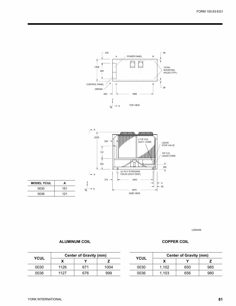
YORK INTERNATIONAL80 YORK INTERNATIONAL 81
FORM 150.63-EG1
LD04448
������������
��������
�������
��������
�������������������
�����������������
���������
�����������
�������������
������
�
���
�
�
��
�
� ����
�������
���
���
���
���
����
��
��
����
��
�
�����������
�����������
���
������
����������
���������
������������
�
��� ����
�
� �
���
ALUMINUM COIL COPPER COIL
MODEL YCUL A0030 151
0036 121
YCULCenter of Gravity (mm)
X Y Z0030 1126 671 10040036 1127 676 999
YCULCenter of Gravity (mm)
X Y Z0030 1,102 650 9850036 1,103 656 980
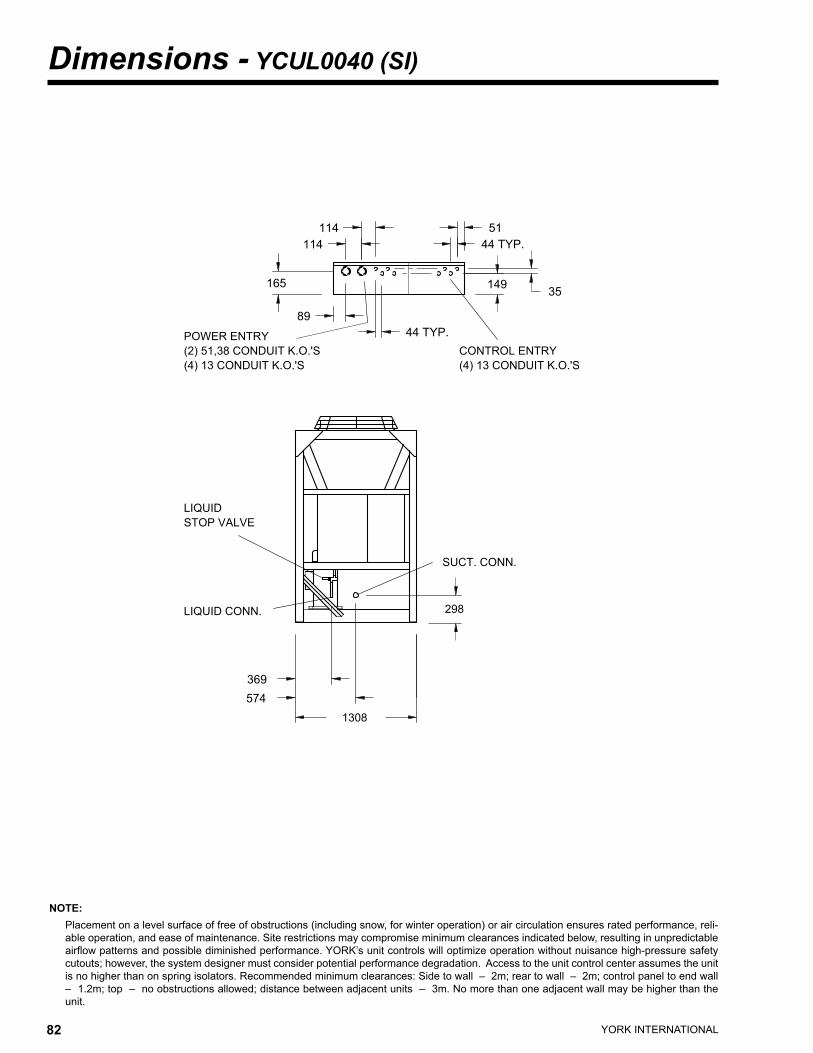
YORK INTERNATIONAL82 YORK INTERNATIONAL 83
FORM 150.63-EG1
NOTE: Placement on a level surface of free of obstructions (including snow, for winter operation) or air circulation ensures rated performance, reli-
able operation, and ease of maintenance. Site restrictions may compromise minimum clearances indicated below, resulting in unpredictable airflow patterns and possible diminished performance. YORK’s unit controls will optimize operation without nuisance high-pressure safety cutouts; however, the system designer must consider potential performance degradation. Access to the unit control center assumes the unit is no higher than on spring isolators. Recommended minimum clearances: Side to wall – 2m; rear to wall – 2m; control panel to end wall – 1.2m; top – no obstructions allowed; distance between adjacent units – 3m. No more than one adjacent wall may be higher than the unit.
Dimensions - YCUL0040 (SI)
�������������
���������������������
�����������
������������������������
���������������������
�������
�������
����
�����
���
��
��
���
���
���
���
�����������
������
����������
������������
���
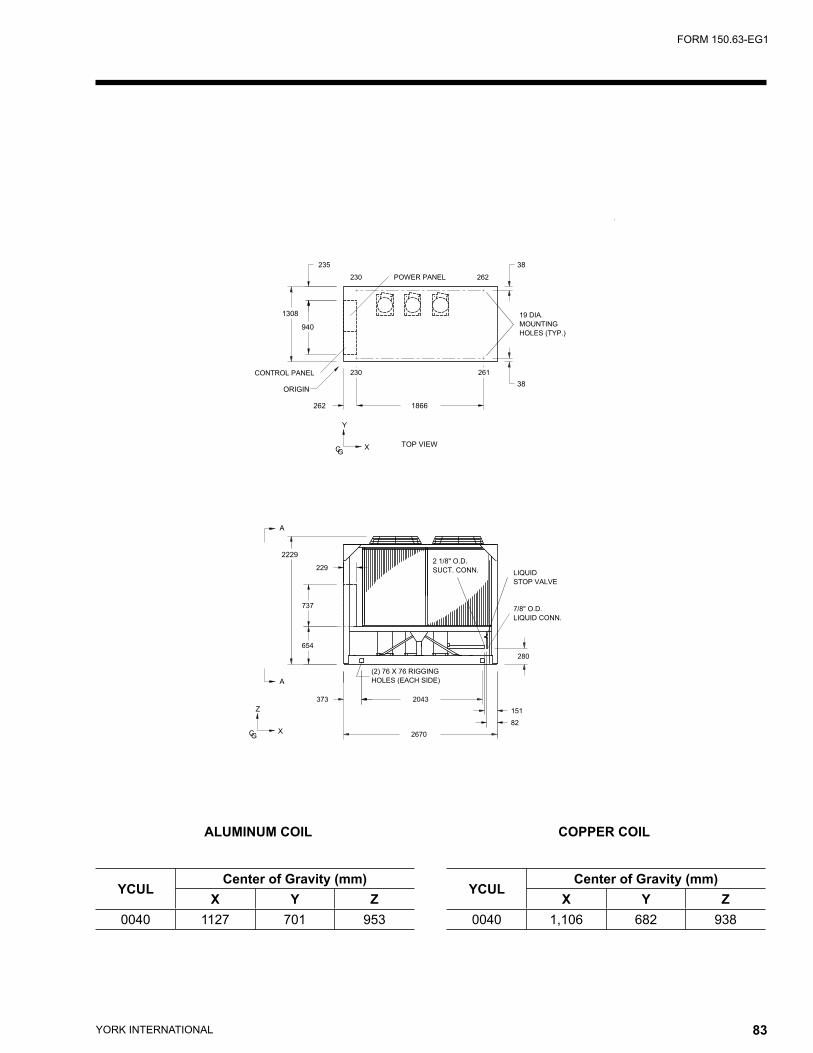
YORK INTERNATIONAL82 YORK INTERNATIONAL 83
FORM 150.63-EG1
ALUMINUM COIL COPPER COIL
YCULCenter of Gravity (mm)
X Y Z0040 1127 701 953
YCULCenter of Gravity (mm)
X Y Z0040 1,106 682 938
������������
��������
�������
��������
�������������������
�����������������
�����������
�������������
������
�
���
�
�
��
�
� ����
�������
���
���
���
���
����
��
��
����
��
���
�����������
�����������
���
������
����������
���������
������������
���
��� ����
���
��� ���
���
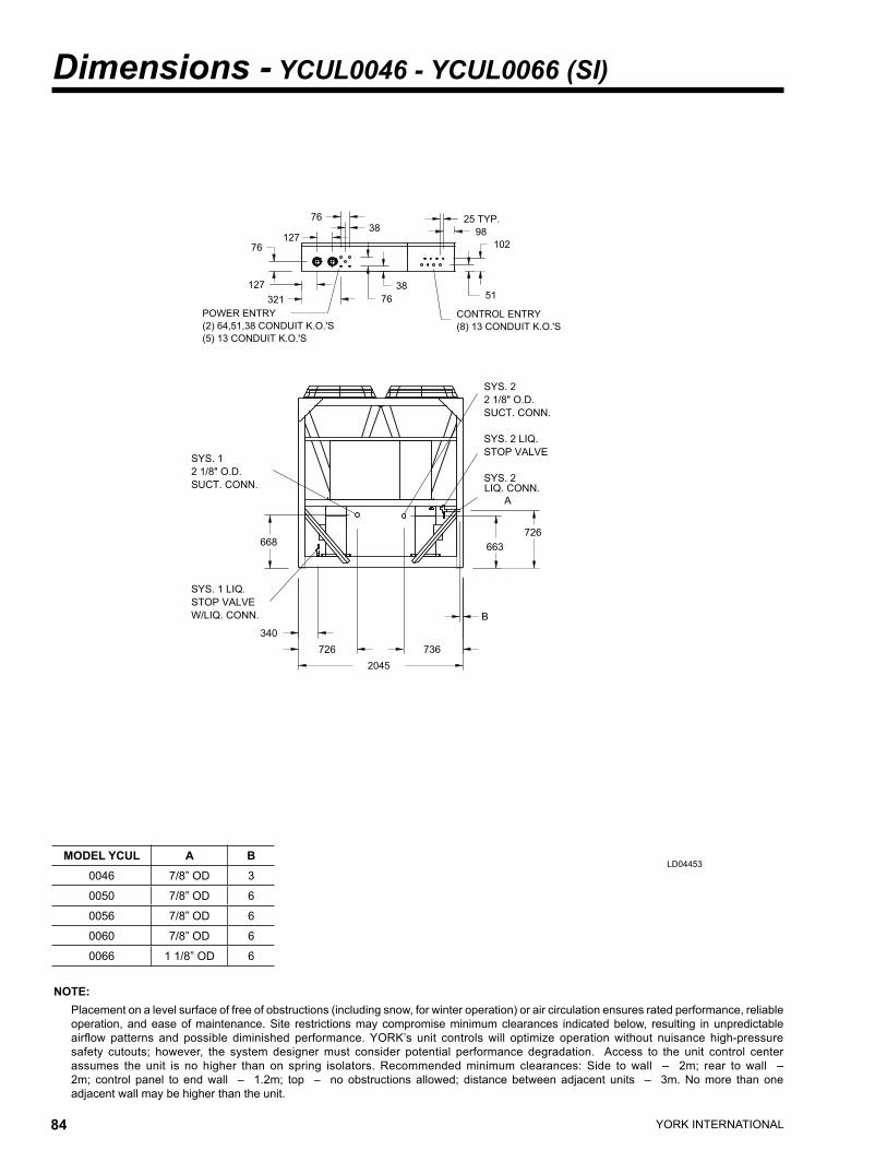
YORK INTERNATIONAL84 YORK INTERNATIONAL 85
FORM 150.63-EG1
NOTE: Placement on a level surface of free of obstructions (including snow, for winter operation) or air circulation ensures rated performance, reliable
operation, and ease of maintenance. Site restrictions may compromise minimum clearances indicated below, resulting in unpredictable airflow patterns and possible diminished performance. YORK’s unit controls will optimize operation without nuisance high-pressure safety cutouts; however, the system designer must consider potential performance degradation. Access to the unit control center assumes the unit is no higher than on spring isolators. Recommended minimum clearances: Side to wall – 2m; rear to wall – 2m; control panel to end wall – 1.2m; top – no obstructions allowed; distance between adjacent units – 3m. No more than one adjacent wall may be higher than the unit.
Dimensions - YCUL0046 - YCUL0066 (SI)
LD04453
��������������������������� ���������������������
���������������������
����
�����������
��
�������������
�����
���
�����
��
��
��
���������
���
���
������
�����������
������
����������������
��������
���
���
�
���
�����������
����������
�����������
�����������
�����������
������
�����������
�����������
������������
MODEL YCUL A B0046 7/8” OD 3
0050 7/8” OD 6
0056 7/8” OD 6
0060 7/8” OD 6
0066 1 1/8” OD 6
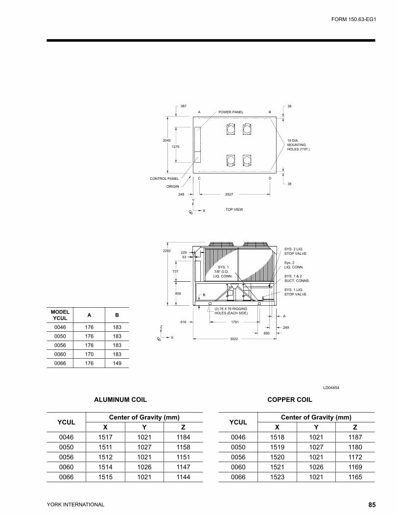
YORK INTERNATIONAL84 YORK INTERNATIONAL 85
FORM 150.63-EG1
LD04454
�����������������
�������������������
�������
������������
��������
�������������
�����������
��������
������
���
�
��� ����
����
���
���
�������
��
����
����
��
��
�
����������
������������
������
���������
����������
������
�����������
����������
����������
���
���
�
�����������
�����������
�
���
�
�
����
� �
���
���
ALUMINUM COIL COPPER COIL
MODEL YCUL A B
0046 176 183
0050 176 183
0056 176 183
0060 170 183
0066 176 149
YCULCenter of Gravity (mm)
X Y Z0046 1517 1021 11840050 1511 1027 11580056 1512 1021 11510060 1514 1026 11470066 1515 1021 1144
YCULCenter of Gravity (mm)
X Y Z0046 1518 1021 11870050 1519 1027 11800056 1520 1021 11720060 1521 1026 11690066 1523 1021 1165
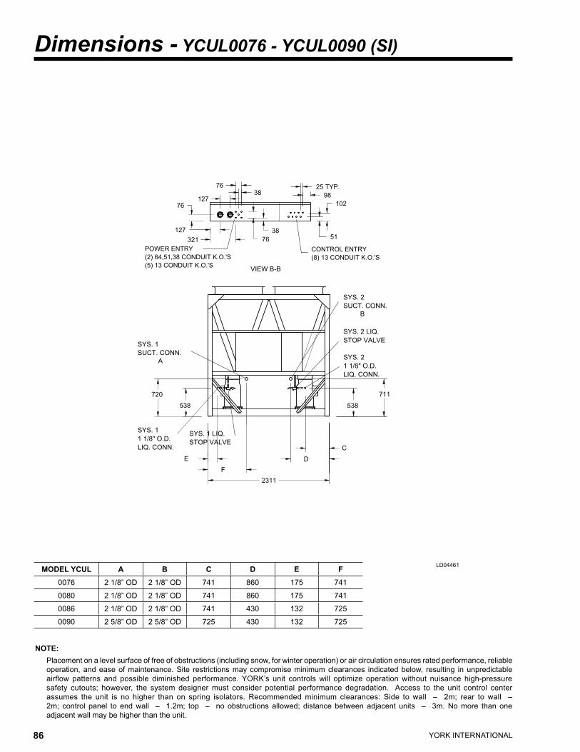
MODEL YCUL A B C D E F0076 2 1/8” OD 2 1/8” OD 741 860 175 741
0080 2 1/8” OD 2 1/8” OD 741 860 175 741
0086 2 1/8” OD 2 1/8” OD 741 430 132 725
0090 2 5/8” OD 2 5/8” OD 725 430 132 725
YORK INTERNATIONAL86 YORK INTERNATIONAL 87
FORM 150.63-EG1
NOTE: Placement on a level surface of free of obstructions (including snow, for winter operation) or air circulation ensures rated performance, reliable
operation, and ease of maintenance. Site restrictions may compromise minimum clearances indicated below, resulting in unpredictable airflow patterns and possible diminished performance. YORK’s unit controls will optimize operation without nuisance high-pressure safety cutouts; however, the system designer must consider potential performance degradation. Access to the unit control center assumes the unit is no higher than on spring isolators. Recommended minimum clearances: Side to wall – 2m; rear to wall – 2m; control panel to end wall – 1.2m; top – no obstructions allowed; distance between adjacent units – 3m. No more than one adjacent wall may be higher than the unit.
Dimensions - YCUL0076 - YCUL0090 (SI)
LD04461
����������
���
������
�����������
�
��������
����
����
�����
���
���
����
��
�������������
���������������������
��
�������
�����������
���������������������������
���������������������
���
������
�����������
����������
�����������
������������
���
�
�
������
����������
�����������
����������
���
�����������
���
�
�����������
�����������
������
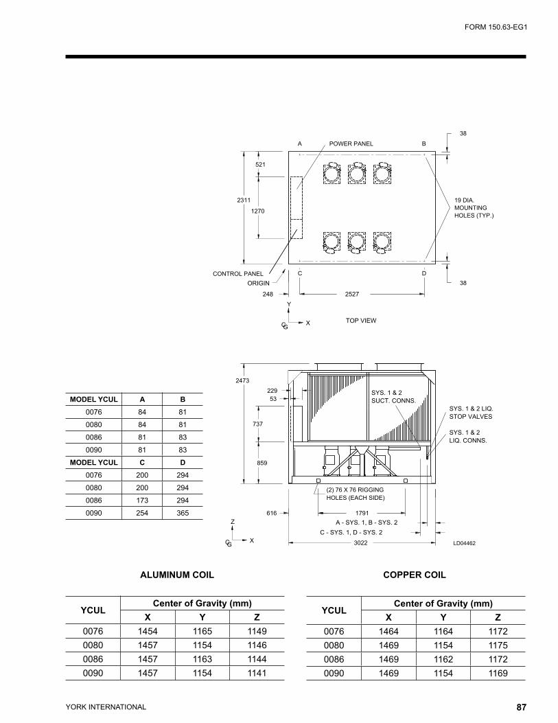
ALUMINUM COIL COPPER COIL
MODEL YCUL A B0076 84 81
0080 84 81
0086 81 83
0090 81 83
MODEL YCUL C D0076 200 294
0080 200 294
0086 173 294
0090 254 365
YORK INTERNATIONAL86 YORK INTERNATIONAL 87
FORM 150.63-EG1
LD04462
�������������������
�������
��������
������������
�����������������
�������������
��������
�����������
������
����
���
����
����
���
���
��
��
��
�
�
��
���
����������������������
�����������
������������
����������
����������
��� ����
����
����������������������
���������������
������������
�
���
��
�
�
�
����
� �
YCULCenter of Gravity (mm)
X Y Z0076 1454 1165 11490080 1457 1154 11460086 1457 1163 11440090 1457 1154 1141
YCULCenter of Gravity (mm)
X Y Z0076 1464 1164 11720080 1469 1154 11750086 1469 1162 11720090 1469 1154 1169
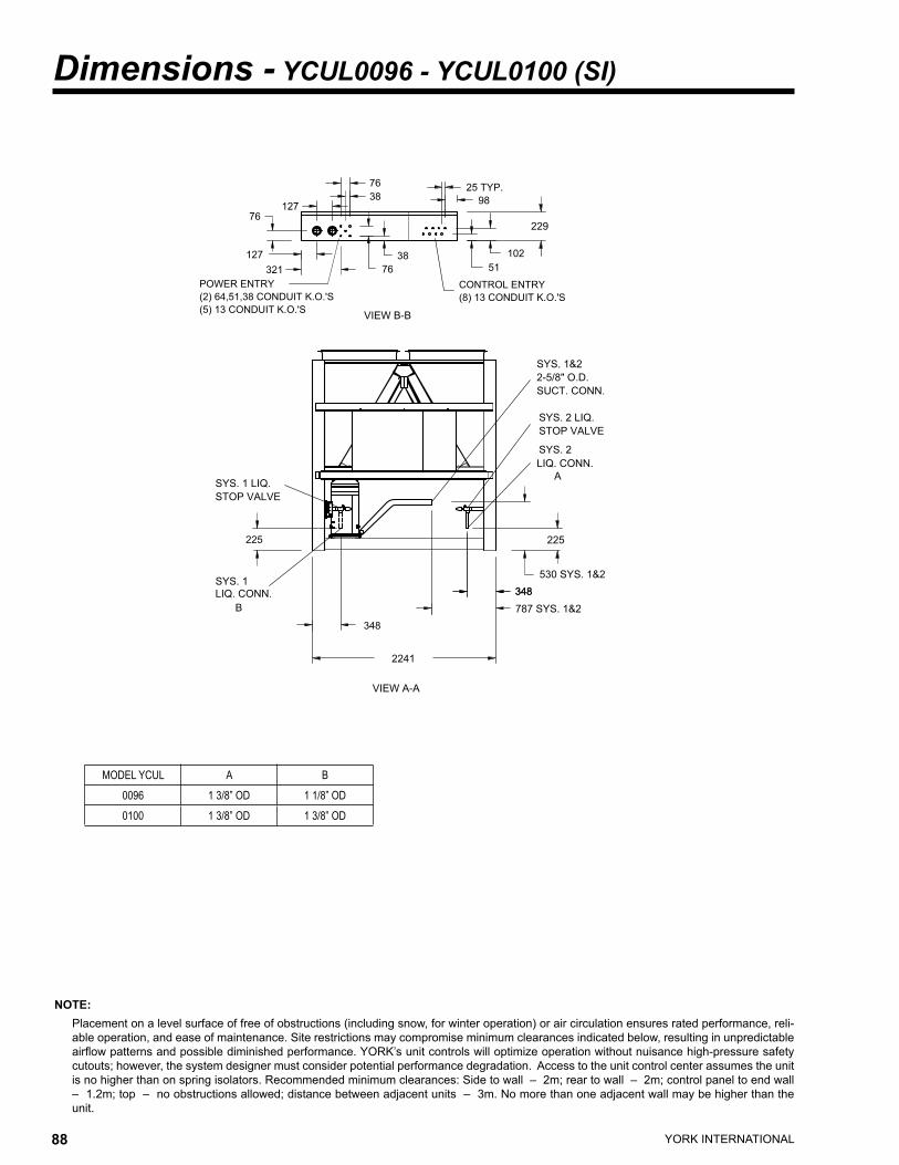
YORK INTERNATIONAL88 YORK INTERNATIONAL 89
FORM 150.63-EG1
NOTE: Placement on a level surface of free of obstructions (including snow, for winter operation) or air circulation ensures rated performance, reli-
able operation, and ease of maintenance. Site restrictions may compromise minimum clearances indicated below, resulting in unpredictable airflow patterns and possible diminished performance. YORK’s unit controls will optimize operation without nuisance high-pressure safety cutouts; however, the system designer must consider potential performance degradation. Access to the unit control center assumes the unit is no higher than on spring isolators. Recommended minimum clearances: Side to wall – 2m; rear to wall – 2m; control panel to end wall – 1.2m; top – no obstructions allowed; distance between adjacent units – 3m. No more than one adjacent wall may be higher than the unit.
Dimensions - YCUL0096 - YCUL0100 (SI)
���
������������
��
���������������������
��
���������������������������
���
�����������
���
���
�� ��
��
�������������
���������������������
��
�������
���
���
��
��������
��������
����
�
�����������
�����������
���
������
����������
������������
���
���
���
��������
�����������
�����������
�����������
����������
������
����������
�������
MODEL YCUL A B0096 1 3/8” OD 1 1/8” OD0100 1 3/8” OD 1 3/8” OD
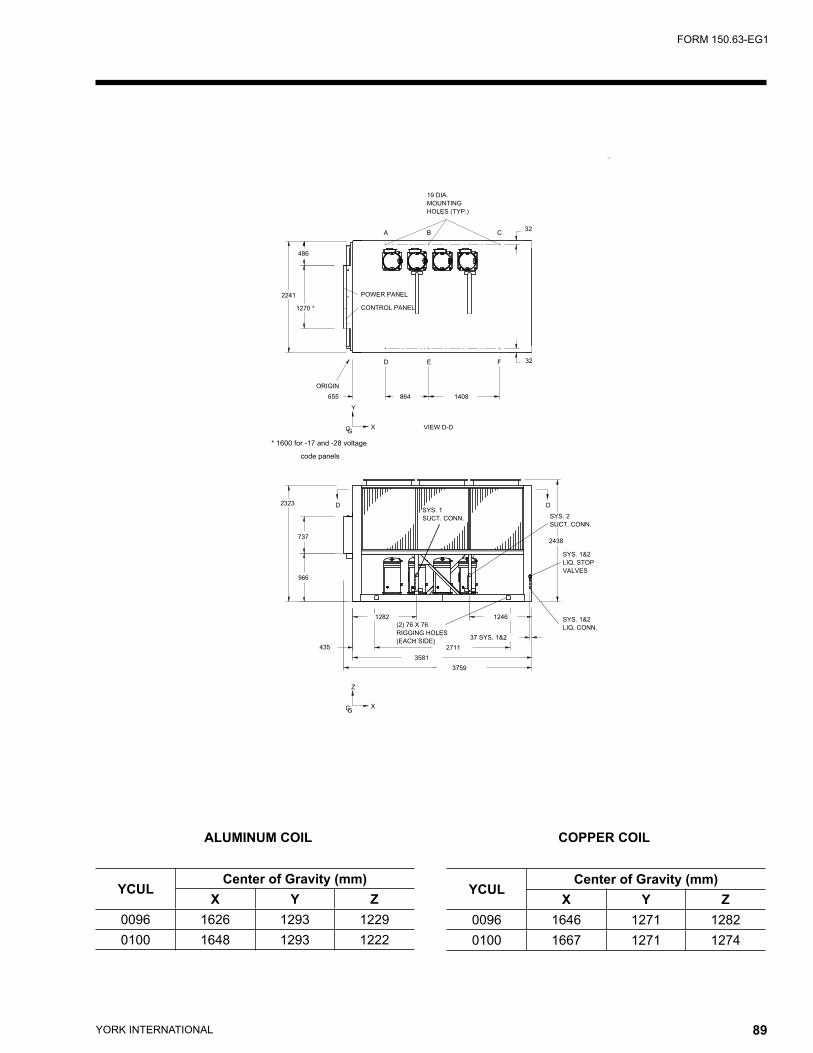
YORK INTERNATIONAL88 YORK INTERNATIONAL 89
FORM 150.63-EG1
ALUMINUM COIL COPPER COIL
YCULCenter of Gravity (mm)
X Y Z0096 1626 1293 12290100 1648 1293 1222
YCULCenter of Gravity (mm)
X Y Z0096 1646 1271 12820100 1667 1271 1274
������
�������������
�����������
�����������
�������
������������
��������
��������
������
�������������
�����������
���
�
���
����
����
����
���
�
����
����
�
���
�
��� ���
� �
� �
����
�
�
����
���
���
����
�����������
������
�����������
������
��������
���������
������
��������
����������
����
������������
��
��
�������������������������������
�����������
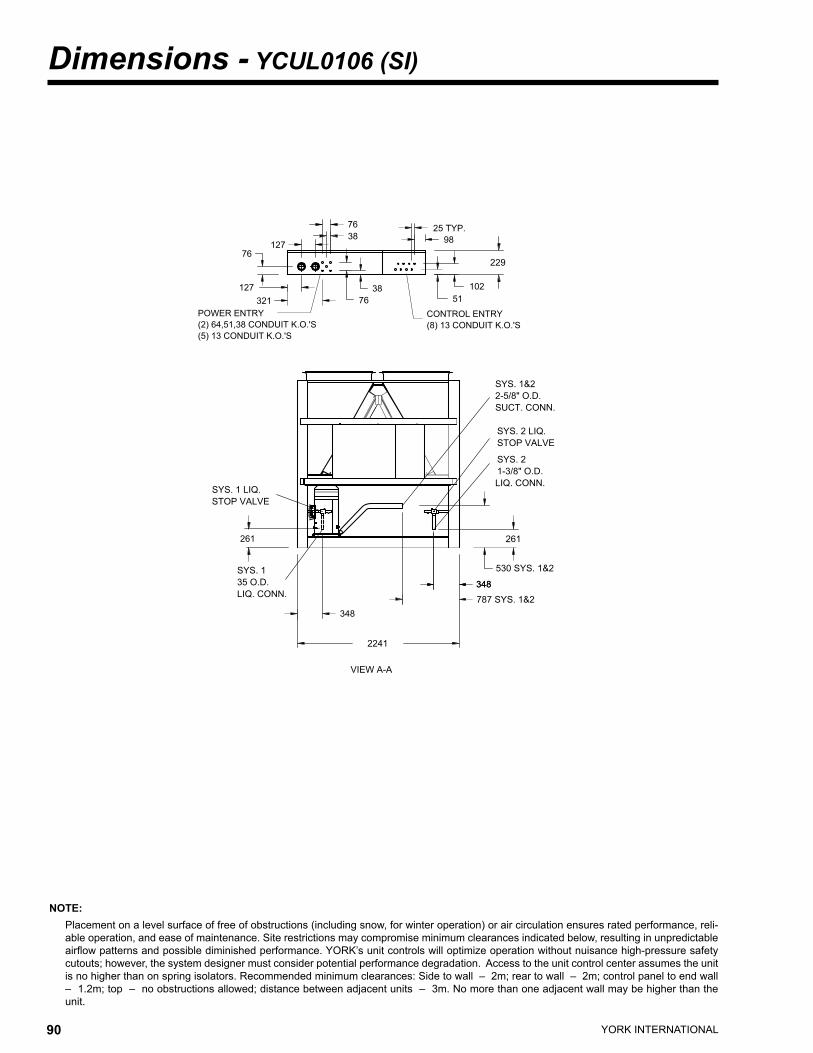
YORK INTERNATIONAL90 YORK INTERNATIONAL 91
FORM 150.63-EG1
Dimensions - YCUL0106 (SI)
NOTE: Placement on a level surface of free of obstructions (including snow, for winter operation) or air circulation ensures rated performance, reli-
able operation, and ease of maintenance. Site restrictions may compromise minimum clearances indicated below, resulting in unpredictable airflow patterns and possible diminished performance. YORK’s unit controls will optimize operation without nuisance high-pressure safety cutouts; however, the system designer must consider potential performance degradation. Access to the unit control center assumes the unit is no higher than on spring isolators. Recommended minimum clearances: Side to wall – 2m; rear to wall – 2m; control panel to end wall – 1.2m; top – no obstructions allowed; distance between adjacent units – 3m. No more than one adjacent wall may be higher than the unit.
���
������������
��
��������
���������������������
��
���������������������������
���
�����������
���
���
�� ��
��
�������������
���������������������
��
�������
���
���
��
����
�����������
�����������
���
������
�������
����������
������������
���
���
���
��������
�����������
�����������
�����������
����������
������
�����������
����������
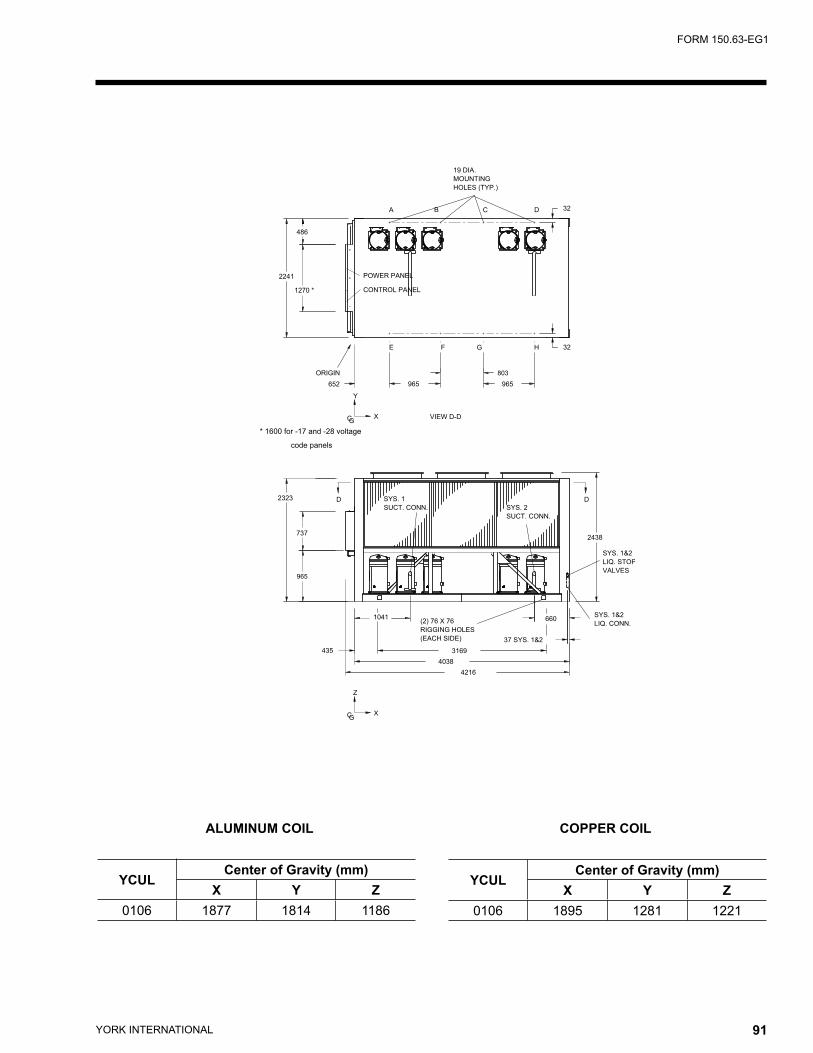
YORK INTERNATIONAL90 YORK INTERNATIONAL 91
FORM 150.63-EG1
ALUMINUM COIL COPPER COIL
YCULCenter of Gravity (mm)
X Y Z0106 1877 1814 1186
YCULCenter of Gravity (mm)
X Y Z0106 1895 1281 1221
�������������
�����������
�����������
�������
������������
��������
������
��������
�������������
�����������
������
���
���
�
����
����
����
���
���� �
����
�
�
�
���
����
���
�
�
���
�
���
� ��
� ��
���
�
�
���
���
����
�����������
������
�����������
������
��������
���������
������
��������
�������������
������������
�������������������������������
�����������
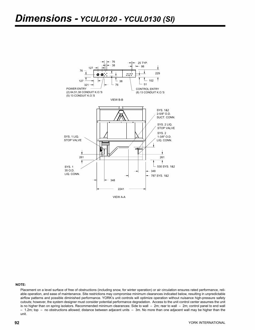
YORK INTERNATIONAL92 YORK INTERNATIONAL 93
FORM 150.63-EG1
NOTE: Placement on a level surface of free of obstructions (including snow, for winter operation) or air circulation ensures rated performance, reli-
able operation, and ease of maintenance. Site restrictions may compromise minimum clearances indicated below, resulting in unpredictable airflow patterns and possible diminished performance. YORK’s unit controls will optimize operation without nuisance high-pressure safety cutouts; however, the system designer must consider potential performance degradation. Access to the unit control center assumes the unit is no higher than on spring isolators. Recommended minimum clearances: Side to wall – 2m; rear to wall – 2m; control panel to end wall – 1.2m; top – no obstructions allowed; distance between adjacent units – 3m. No more than one adjacent wall may be higher than the unit.
Dimensions - YCUL0120 - YCUL0130 (SI)
���
������������
��
������������������������������������������������
���������������������
��
�����������
���
���
���
�������������
��
����
���
�������
��
���
��
��������
��������
����
������
����������
�������
�����������
�����������
��������
�����������
�����������
�����������
����������
������
�����������
����������
���
������������
���
���
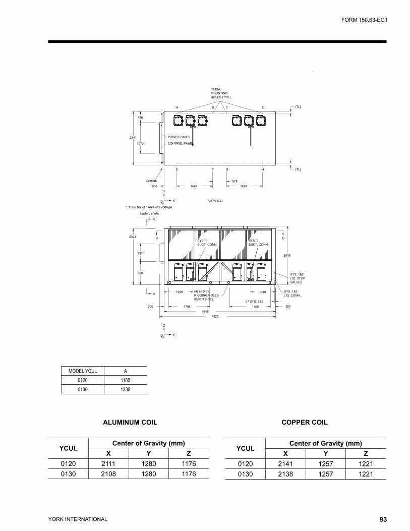
YORK INTERNATIONAL92 YORK INTERNATIONAL 93
FORM 150.63-EG1
ALUMINUM COIL COPPER COIL
YCULCenter of Gravity (mm)
X Y Z0120 2111 1280 11760130 2108 1280 1176
YCULCenter of Gravity (mm)
X Y Z0120 2141 1257 12210130 2138 1257 1221
������
������
�������������
�����������
��������
�����������
��������
�����������
�������������
������������
�������
�
�
��
���
����
�
���
�
�
��
���
����
���
����
�
����
����
�
�
����
� � ����
� � � ����
����
�
���� ���
���
�
�
����
���
������
�����������
������
�����������
���������
������
��������
��������
�������������� ����
������������
�������������������������������
�����������
MODEL YCUL A0120 11850130 1235
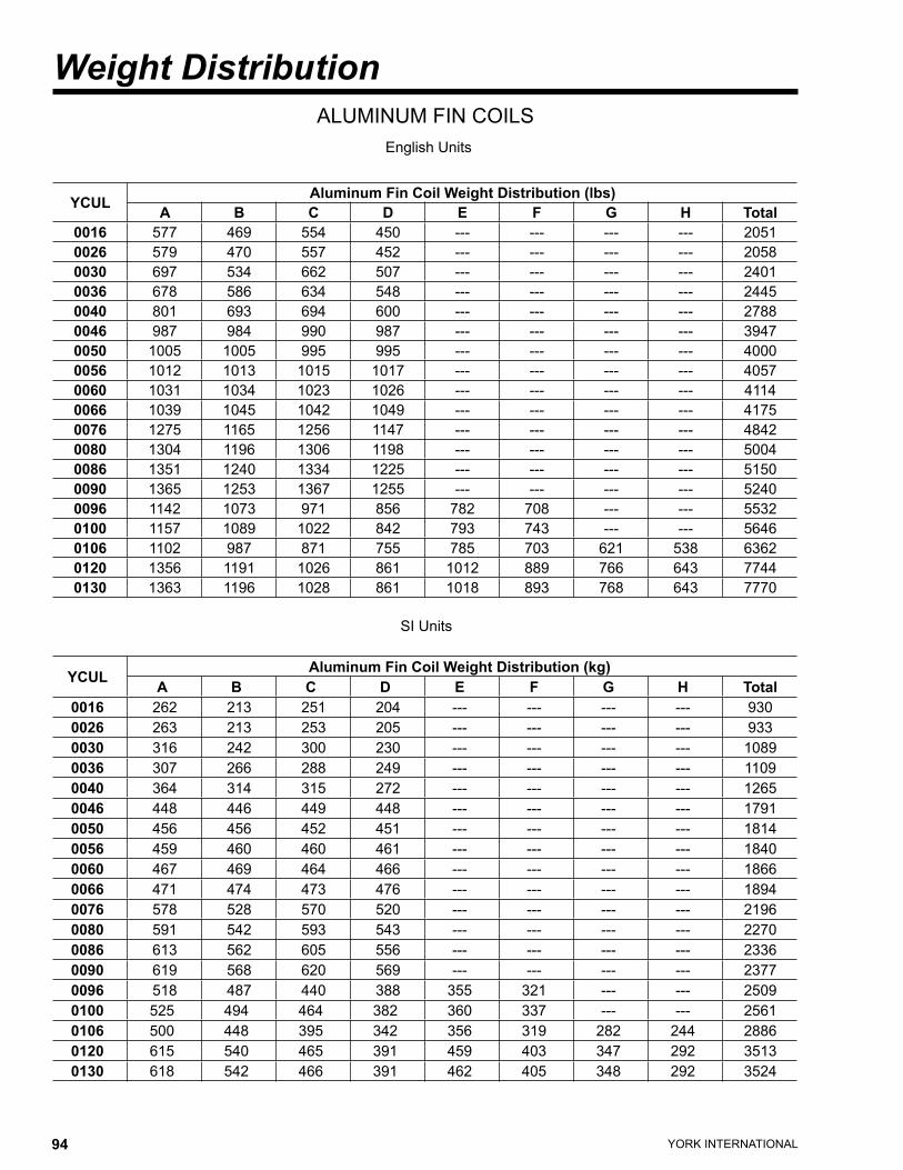
YORK INTERNATIONAL94 YORK INTERNATIONAL 95
FORM 150.63-EG1
YCUL Aluminum Fin Coil Weight Distribution (lbs)A B C D E F G H Total
0016 577 469 554 450 --- --- --- --- 20510026 579 470 557 452 --- --- --- --- 20580030 697 534 662 507 --- --- --- --- 24010036 678 586 634 548 --- --- --- --- 24450040 801 693 694 600 --- --- --- --- 27880046 987 984 990 987 --- --- --- --- 39470050 1005 1005 995 995 --- --- --- --- 40000056 1012 1013 1015 1017 --- --- --- --- 40570060 1031 1034 1023 1026 --- --- --- --- 41140066 1039 1045 1042 1049 --- --- --- --- 41750076 1275 1165 1256 1147 --- --- --- --- 48420080 1304 1196 1306 1198 --- --- --- --- 50040086 1351 1240 1334 1225 --- --- --- --- 51500090 1365 1253 1367 1255 --- --- --- --- 52400096 1142 1073 971 856 782 708 --- --- 55320100 1157 1089 1022 842 793 743 --- --- 56460106 1102 987 871 755 785 703 621 538 63620120 1356 1191 1026 861 1012 889 766 643 77440130 1363 1196 1028 861 1018 893 768 643 7770
ALUMINUM FIN COILSEnglish Units
YCUL Aluminum Fin Coil Weight Distribution (kg)A B C D E F G H Total
0016 262 213 251 204 --- --- --- --- 9300026 263 213 253 205 --- --- --- --- 9330030 316 242 300 230 --- --- --- --- 10890036 307 266 288 249 --- --- --- --- 11090040 364 314 315 272 --- --- --- --- 12650046 448 446 449 448 --- --- --- --- 17910050 456 456 452 451 --- --- --- --- 18140056 459 460 460 461 --- --- --- --- 18400060 467 469 464 466 --- --- --- --- 18660066 471 474 473 476 --- --- --- --- 18940076 578 528 570 520 --- --- --- --- 21960080 591 542 593 543 --- --- --- --- 22700086 613 562 605 556 --- --- --- --- 23360090 619 568 620 569 --- --- --- --- 23770096 518 487 440 388 355 321 --- --- 25090100 525 494 464 382 360 337 --- --- 25610106 500 448 395 342 356 319 282 244 28860120 615 540 465 391 459 403 347 292 35130130 618 542 466 391 462 405 348 292 3524
SI Units
Weight Distribution
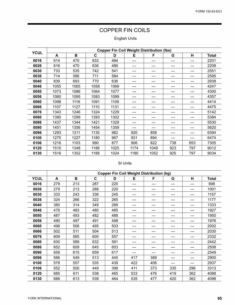
YORK INTERNATIONAL94 YORK INTERNATIONAL 95
FORM 150.63-EG1
YCUL Copper Fin Coil Weight Distribution (lbs)A B C D E F G H Total
0016 614 470 633 484 --- --- --- --- 22010026 616 470 636 486 --- --- --- --- 22080030 733 535 742 541 --- --- --- --- 25510036 714 586 711 584 --- --- --- --- 25950040 839 693 770 636 --- --- --- --- 29380046 1055 1065 1058 1069 --- --- --- --- 42470050 1073 1086 1064 1077 --- --- --- --- 43000056 1080 1095 1083 1099 --- --- --- --- 43570060 1098 1116 1091 1109 --- --- --- --- 44140066 1107 1127 1110 1131 --- --- --- --- 44750076 1343 1246 1324 1229 --- --- --- --- 51420080 1390 1299 1393 1302 --- --- --- --- 53840086 1437 1344 1421 1329 --- --- --- --- 55300090 1451 1356 1454 1359 --- --- --- --- 56200096 1293 1211 1130 982 920 858 --- --- 63940100 1275 1227 1180 967 931 894 --- --- 64740106 1216 1103 990 877 906 822 738 653 73050120 1510 1348 1186 1025 1174 1049 923 797 90120130 1516 1352 1188 1024 1180 1052 925 797 9034
Copper Fin Coil Weight Distribution (kg)YCUL A B C D E F G H Total0016 279 213 287 220 --- --- --- --- 9980026 279 213 288 220 --- --- --- --- 10010030 333 243 336 245 --- --- --- --- 11570036 324 266 322 265 --- --- --- --- 11770040 380 314 349 289 --- --- --- --- 13330046 478 483 480 485 --- --- --- --- 19270050 487 493 482 488 --- --- --- --- 19500056 490 497 491 498 --- --- --- --- 19760060 498 506 495 503 --- --- --- --- 20020066 502 511 504 513 --- --- --- --- 20300076 609 565 600 557 --- --- --- --- 23320080 630 589 632 591 --- --- --- --- 24420086 652 609 645 603 --- --- --- --- 25080090 658 615 659 617 --- --- --- --- 25490096 586 549 513 445 417 389 --- --- 29000100 578 557 535 439 422 406 --- --- 29370106 552 500 449 398 411 373 335 296 33130120 685 611 538 465 533 476 419 362 40880130 688 613 539 464 535 477 420 362 4098
COPPER FIN COILSEnglish Units
SI Units
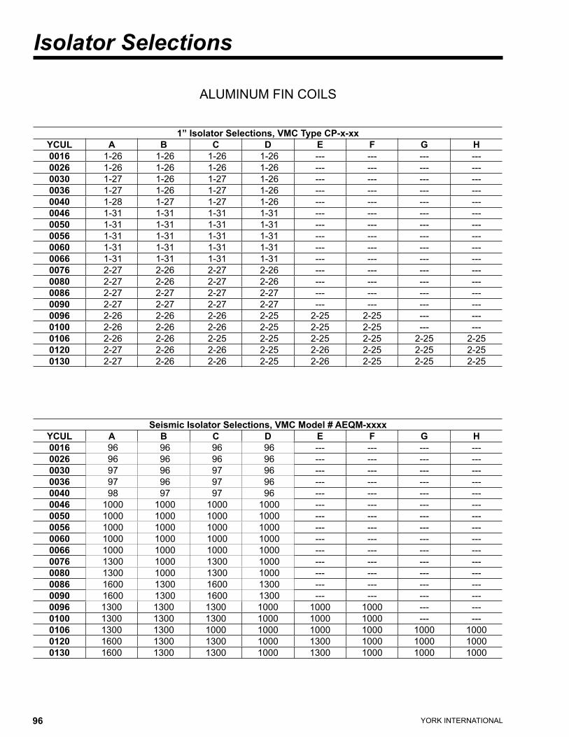
YORK INTERNATIONAL96 YORK INTERNATIONAL 97
FORM 150.63-EG1
Seismic Isolator Selections, VMC Model # AEQM-xxxxYCUL A B C D E F G H0016 96 96 96 96 --- --- --- ---0026 96 96 96 96 --- --- --- ---0030 97 96 97 96 --- --- --- ---0036 97 96 97 96 --- --- --- ---0040 98 97 97 96 --- --- --- ---0046 1000 1000 1000 1000 --- --- --- ---0050 1000 1000 1000 1000 --- --- --- ---0056 1000 1000 1000 1000 --- --- --- ---0060 1000 1000 1000 1000 --- --- --- ---0066 1000 1000 1000 1000 --- --- --- ---0076 1300 1000 1300 1000 --- --- --- ---0080 1300 1000 1300 1000 --- --- --- ---0086 1600 1300 1600 1300 --- --- --- ---0090 1600 1300 1600 1300 --- --- --- ---0096 1300 1300 1300 1000 1000 1000 --- ---0100 1300 1300 1300 1000 1000 1000 --- ---0106 1300 1300 1000 1000 1000 1000 1000 10000120 1600 1300 1300 1000 1300 1000 1000 10000130 1600 1300 1300 1000 1300 1000 1000 1000
ALUMINUM FIN COILS
1” Isolator Selections, VMC Type CP-x-xxYCUL A B C D E F G H0016 1-26 1-26 1-26 1-26 --- --- --- ---0026 1-26 1-26 1-26 1-26 --- --- --- ---0030 1-27 1-26 1-27 1-26 --- --- --- ---0036 1-27 1-26 1-27 1-26 --- --- --- ---0040 1-28 1-27 1-27 1-26 --- --- --- ---0046 1-31 1-31 1-31 1-31 --- --- --- ---0050 1-31 1-31 1-31 1-31 --- --- --- ---0056 1-31 1-31 1-31 1-31 --- --- --- ---0060 1-31 1-31 1-31 1-31 --- --- --- ---0066 1-31 1-31 1-31 1-31 --- --- --- ---0076 2-27 2-26 2-27 2-26 --- --- --- ---0080 2-27 2-26 2-27 2-26 --- --- --- ---0086 2-27 2-27 2-27 2-27 --- --- --- ---0090 2-27 2-27 2-27 2-27 --- --- --- ---0096 2-26 2-26 2-26 2-25 2-25 2-25 --- ---0100 2-26 2-26 2-26 2-25 2-25 2-25 --- ---0106 2-26 2-26 2-25 2-25 2-25 2-25 2-25 2-250120 2-27 2-26 2-26 2-25 2-26 2-25 2-25 2-250130 2-27 2-26 2-26 2-25 2-26 2-25 2-25 2-25
Isolator Selections

YORK INTERNATIONAL96 YORK INTERNATIONAL 97
FORM 150.63-EG1
VMC Type RD NeopreneYCUL A B C D E F G H0016 -3 Grn -3 Red -3 Grn -3 Red --- --- --- ---0026 -3 Grn -3 Red -3 Grn -3 Red --- --- --- ---0030 -3 Grn -3 Grn -3 Grn -3 Red --- --- --- ---0036 -3 Grn -3 Grn -3 Grn -3 Red --- --- --- ---0040 -3 Gray -3 Gray -3 Gray -3 Gray --- --- --- ---0046 -3 Gray -3 Gray -3 Gray -3 Gray --- --- --- ---0050 -3 Gray -3 Gray -3 Gray -3 Gray --- --- --- ---0056 -3 Gray -3 Gray -3 Gray -3 Gray --- --- --- ---0060 -3 Gray -3 Gray -3 Gray -3 Gray --- --- --- ---0066 -3 Gray -3 Gray -3 Gray -3 Gray --- --- --- ---0076 -4 Blk -4 Blk -4 Blk -4 Blk --- --- --- ---0080 -4 Blk -4 Blk -4 Blk -4 Blk --- --- --- ---0086 -4 Blk -4 Blk -4 Blk -4 Blk --- --- --- ---0090 -4 Blk -4 Blk -4 Blk -4 Blk --- --- --- ---0096 -4 Blk -3 Gray -3 Gray -3 Gray -3 Gray -3 Grn --- ---0100 -4 Blk -3 Gray -3 Gray -3 Gray -3 Gray -3 Grn --- ---0106 -4 Blk -3 Gray -3 Gray -3 Gray -3 Gray -3 Grn -3 Grn -2 Gray0120 -4 Blk -4 Blk -3 Gray -3 Gray -3 Gray -3 Gray -3 Gray -3 Grn0130 -4 Blk -4 Blk -3 Gray -3 Gray -3 Gray -3 Gray -3 Gray -3 Grn
ALUMINUM FIN COILS
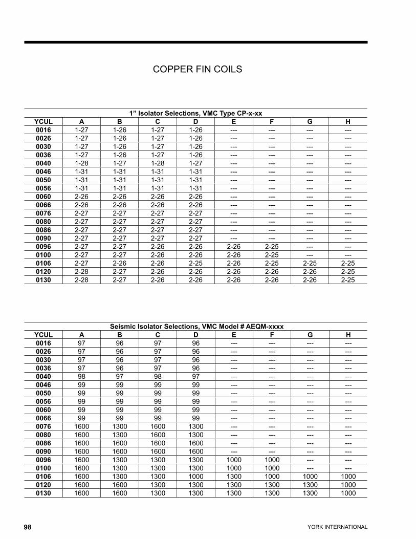
YORK INTERNATIONAL98 YORK INTERNATIONAL 99
FORM 150.63-EG1
COPPER FIN COILS
Seismic Isolator Selections, VMC Model # AEQM-xxxxYCUL A B C D E F G H0016 97 96 97 96 --- --- --- ---0026 97 96 97 96 --- --- --- ---0030 97 96 97 96 --- --- --- ---0036 97 96 97 96 --- --- --- ---0040 98 97 98 97 --- --- --- ---0046 99 99 99 99 --- --- --- ---0050 99 99 99 99 --- --- --- ---0056 99 99 99 99 --- --- --- ---0060 99 99 99 99 --- --- --- ---0066 99 99 99 99 --- --- --- ---0076 1600 1300 1600 1300 --- --- --- ---0080 1600 1300 1600 1300 --- --- --- ---0086 1600 1600 1600 1600 --- --- --- ---0090 1600 1600 1600 1600 --- --- --- ---0096 1600 1300 1300 1300 1000 1000 --- ---0100 1600 1300 1300 1300 1000 1000 --- ---0106 1600 1300 1300 1000 1300 1000 1000 10000120 1600 1600 1300 1300 1300 1300 1300 10000130 1600 1600 1300 1300 1300 1300 1300 1000
1” Isolator Selections, VMC Type CP-x-xxYCUL A B C D E F G H0016 1-27 1-26 1-27 1-26 --- --- --- ---0026 1-27 1-26 1-27 1-26 --- --- --- ---0030 1-27 1-26 1-27 1-26 --- --- --- ---0036 1-27 1-26 1-27 1-26 --- --- --- ---0040 1-28 1-27 1-28 1-27 --- --- --- ---0046 1-31 1-31 1-31 1-31 --- --- --- ---0050 1-31 1-31 1-31 1-31 --- --- --- ---0056 1-31 1-31 1-31 1-31 --- --- --- ---0060 2-26 2-26 2-26 2-26 --- --- --- ---0066 2-26 2-26 2-26 2-26 --- --- --- ---0076 2-27 2-27 2-27 2-27 --- --- --- ---0080 2-27 2-27 2-27 2-27 --- --- --- ---0086 2-27 2-27 2-27 2-27 --- --- --- ---0090 2-27 2-27 2-27 2-27 --- --- --- ---0096 2-27 2-27 2-26 2-26 2-26 2-25 --- ---0100 2-27 2-27 2-26 2-26 2-26 2-25 --- ---0106 2-27 2-26 2-26 2-25 2-26 2-25 2-25 2-250120 2-28 2-27 2-26 2-26 2-26 2-26 2-26 2-250130 2-28 2-27 2-26 2-26 2-26 2-26 2-26 2-25
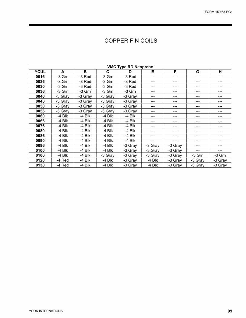
YORK INTERNATIONAL98 YORK INTERNATIONAL 99
FORM 150.63-EG1
VMC Type RD NeopreneYCUL A B C D E F G H0016 -3 Grn -3 Red -3 Grn -3 Red --- --- --- ---0026 -3 Grn -3 Red -3 Grn -3 Red --- --- --- ---0030 -3 Grn -3 Red -3 Grn -3 Red --- --- --- ---0036 -3 Grn -3 Grn -3 Grn -3 Grn --- --- --- ---0040 -3 Gray -3 Gray -3 Gray -3 Gray --- --- --- ---0046 -3 Gray -3 Gray -3 Gray -3 Gray --- --- --- ---0050 -3 Gray -3 Gray -3 Gray -3 Gray --- --- --- ---0056 -3 Gray -3 Gray -3 Gray -3 Gray --- --- --- ---0060 -4 Blk -4 Blk -4 Blk -4 Blk --- --- --- ---0066 -4 Blk -4 Blk -4 Blk -4 Blk --- --- --- ---0076 -4 Blk -4 Blk -4 Blk -4 Blk --- --- --- ---0080 -4 Blk -4 Blk -4 Blk -4 Blk --- --- --- ---0086 -4 Blk -4 Blk -4 Blk -4 Blk --- --- --- ---0090 -4 Blk -4 Blk -4 Blk -4 Blk --- --- --- ---0096 -4 Blk -4 Blk -4 Blk -3 Gray -3 Gray -3 Gray --- ---0100 -4 Blk -4 Blk -4 Blk -3 Gray -3 Gray -3 Gray --- ---0106 -4 Blk -4 Blk -3 Gray -3 Gray -3 Gray -3 Gray -3 Grn -3 Grn0120 -4 Red -4 Blk -4 Blk -3 Gray -4 Blk -3 Gray -3 Gray -3 Gray0130 -4 Red -4 Blk -4 Blk -3 Gray -4 Blk -3 Gray -3 Gray -3 Gray
COPPER FIN COILS

YORK INTERNATIONAL100 YORK INTERNATIONAL 101
FORM 150.63-EG1
Isolators
1" DEFLECTION SEISMICMODEL PART- # COLOR MODEL PART # COLORCP-1-26 308439-26 PURPLE AEQM-96 301055-96 BLACKCP-1-27 308439-27 ORANGE AEQM-97 301055-97 WHITECP-1-28 308439-28 GREEN AEQM-98 301055-98 GRAYCP-1-31 308439-31 GRAY AEQM-99 301055-99 BLUECP-2-25 308439-25 RED AEQM-1000 30106-1000 GREENCP-2-26 308692-26 PURPLE AEQM-1300 30106-1300 YELLOWCP-2-27 308962-27 ORANGE AEQM-1600 301060-1600 GRAYCP-2-28 308692-28 GREEN AEQM-1625 301060-1625 REDCP-2-31 308692-31 GRAY AEQM-1628 301060-1628 GRAY/GREEN
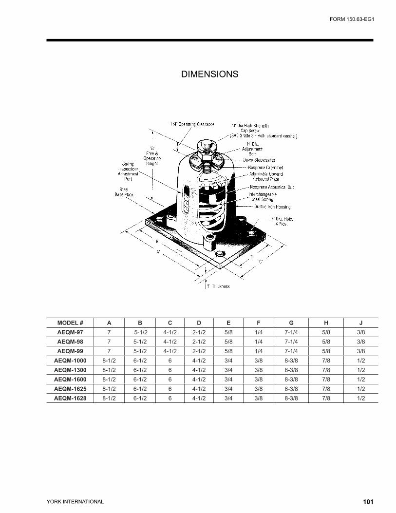
YORK INTERNATIONAL100 YORK INTERNATIONAL 101
FORM 150.63-EG1
MODEL # A B C D E F G H JAEQM-97 7 5-1/2 4-1/2 2-1/2 5/8 1/4 7-1/4 5/8 3/8AEQM-98 7 5-1/2 4-1/2 2-1/2 5/8 1/4 7-1/4 5/8 3/8AEQM-99 7 5-1/2 4-1/2 2-1/2 5/8 1/4 7-1/4 5/8 3/8
AEQM-1000 8-1/2 6-1/2 6 4-1/2 3/4 3/8 8-3/8 7/8 1/2AEQM-1300 8-1/2 6-1/2 6 4-1/2 3/4 3/8 8-3/8 7/8 1/2AEQM-1600 8-1/2 6-1/2 6 4-1/2 3/4 3/8 8-3/8 7/8 1/2AEQM-1625 8-1/2 6-1/2 6 4-1/2 3/4 3/8 8-3/8 7/8 1/2AEQM-1628 8-1/2 6-1/2 6 4-1/2 3/4 3/8 8-3/8 7/8 1/2
DIMENSIONS
YORK INTERNATIONAL102 YORK INTERNATIONAL 103
FORM 150.63-EG1
I . Minimum Circuit Ampacity (MCA) is based on 125% of the rated load amps for the largest motor plus 100% of the rated load amps for all other loads included in the circuit, per N.E.C. Article 430-24. If the optional Factory Mounted Control Transformer is provided, add the following MCA values to the electrical tables for the system providing power to the transformer: -17, add 2.5 amps; -28, add 2.3 amps; -40, add 1.5 amps, -46, add 1.3 amps; -58, add 1 amps.
2. Minimum fuse size is based upon 150% of the rated load amps for the largest motor plus 100% of the rated load amps for all other loads included in the circuit to avoid nuisance trips at start-up due to lock rotor amps. It is not recommended in applications where brown outs, frequent starting and stopping of the unit, and/or operation at ambient temperatures in excess of 95ºF (35ºC) is anticipated.
3. Maximum fuse size is based upon 225% of the rated load amps for the largest motor plus 100% of the rated load amps for all other loads included in the circuit, per N.E.C. Article 440.
4. The minimum recommended disconnect switch is based on 115% of the rated load amps for all loads included in the circuit, per N.E.C. Article 440.
5. Circuit breakers must be UL listed and CSA certified and maximum size is based on 225% of the rated loadamps for the largest motor plus 100% of the rated load amps for all other loads included in the circuit. Exception: YCUL0016 and YCUL0026 must have the optional factory overloads installed to use a standard circuit breaker. Otherwise, an HACR-type circuit breakers must be used. Maximum HACR circuit breaker rating is based on 225% of the rated load amps for the largest motor plus 100% of the rated load amps for all other loads included in the circuit.
6. The “INCOMING WIRE RANGE” is the minimum and maximum wire size that can be accommodated by the unit wiring lugs. The (2) preceding the wire range indicates the number of termination points available per phase of the wire range specified. Actual wire size and number of wires per phase must be determined based on the National Electrical Code, USING COPPER CONNECTORS ONLY. Field wiring must also comply with local codes.
7. A ground lug is provided for each compressor system to accommodate a field grounding conductor per N.E.C. Table 250-95. A control circuit grounding lug is also supplied.
8. The supplied disconnect is a “Disconnecting Means” as defined in the N.E.C. 100, and is intended for isolating the unit for the available power supply to perform maintenance and troubleshooting. This disconnect is not intended to be a Load Break Device.
9. Field Wiring by others which complies to the National Electrical Code & Local Codes.
LEGEND ACR-LINE ACROSS THE LINE START C.B. CIRCUIT BREAKER D.E. DUAL ELEMENT FUSE DISC SW DISCONNECT SWITCH FACT MOUNT CB FACTORY MOUNTED CIRCUIT BREAKER FLA FULL LOAD AMPS HZ HERTZ MAX MAXIMUM MCA MINIMUM CIRCUIT AMPACITY MIN MINIMUM MIN NF MINIMUM NON FUSED RLA RATED LOAD AMPS S.P. WIRE SINGLE POINT WIRING UNIT MTD SERV SW UNIT MOUNTED SERVICE (NON-FUSED DISCONNECT SWITCH) LRA LOCKED ROTOR ARMS
VOLTAGE CODE-17 = 200-3-60-28 = 230-3-60-40 = 380-3-60-46 = 460-3-60-58 = 575-3-60
NOTES:
Electrical Notes

YORK INTERNATIONAL102 YORK INTERNATIONAL 103
FORM 150.63-EG1
YCUL0016 - YCUL0040 SINGLE POINT POWER SUPPLY CONNECTIONS (See Fig. 1)
(One Field Provided Power Supply to the condensing unit. Field connections to Factory Provided Power Terminal Block (standard), Non-Fused Disconnect Switch (optional) or Circuit Breaker (optional).)
OVER CURRENT PROTECTION, UNIT VOLTAGE UNIT VOLTAGE CONTROL POWER MCA SEE NOTE B NFDISC Sw NOTE A MIN MAXMODELS w/oCONTROL TRANS 115-1-60/50 15A 10A 15A 30 A / 240V -17 200-1-60 15A 10A 15A 30 A / 240V -28 230-1-60 15A 10A 15A 30 A / 240VMODELS w/
-40 380-1-60 15A 10A 15A 30 A / 480VCONTROL TRANS -46 460-1-60 15A 10A 15A 30 A / 480V
-58 575-1-60 15A 10A 15A 30 A / 600V
Electrical Data
SINGLE POINT FIELD SUPPLIED WIRING SYSTEM #1 COMPRESSOR & FAN
MODEL YCUL VOLT HZ MCA1
MIN N/F DISC SW2
D.E. FUSE CKT. BKR.5 INCOMING (LUGS) WIRE RANGE6COMPR. #1 COMPR. #2 COMPR. #3 FANS
TERMINAL BLOCK (std)
NF DISC. SWITCH
(opt)
CIRCUIT BREAKER
(opt)MIN3 MAX4 MIN MAX RLA LRA RLA LRA RLA LRA QTY FLA(EA)
0016
200 60 71 100 80 90 80 90 # 10 - # 1 # 14 - 1/0 # 14 - 1/0 24.0 189 24.0 189 — — 2 8.2230 60 70 100 80 90 80 90 # 10 - # 1 # 14 - 1/0 # 14 - 1/0 24.0 189 24.0 189 — — 2 7.8380 60 42 60 50 50 50 50 # 10 - # 1 # 14 - 2 # 14 - 2 14.4 112 14.4 112 — — 2 4.8460 60 35 60 40 45 40 45 # 10 - # 1 # 14 - 2 # 14 - 2 12.0 99 12.0 99 — — 2 4.0575 60 28 30 35 35 35 35 # 10 - # 1 # 14 - 2 # 14 - 2 9.6 74 9.6 74 — — 2 3.1
0026
200 60 92 100 100 110 100 110 # 10 - # 1 # 14 - 1/0 # 14 - 1/0 33.2 278 33.2 278 — — 2 8.2230 60 91 100 100 110 100 110 # 10 - # 1 # 14 - 1/0 # 14 - 1/0 33.2 278 33.2 278 — — 2 7.8380 60 55 60 60 70 60 70 # 10 - # 1 # 14 - 2 # 14 - 2 19.9 151 19.9 151 — — 2 4.8460 60 46 60 50 60 50 60 # 10 - # 1 # 14 - 2 # 14 - 2 16.6 127 16.6 127 — — 2 4.0575 60 37 60 40 45 40 45 # 10 - # 1 # 14 - 2 # 14 - 2 13.3 100 13.3 100 — — 2 3.1
0030
200 60 107 150 125 125 125 125 # 10 - # 1 # 2 - 4/0 # 2 - 4/0 40.0 350 40.0 350 — — 2 8.2230 60 106 150 125 125 125 125 # 10 - # 1 # 2 - 4/0 # 2 - 4/0 40.0 350 40.0 350 — — 2 7.8380 60 64 100 70 80 70 80 # 10 - # 1 # 14 - 1/0 # 14 - 1/0 24.0 195 24.0 195 — — 2 4.8460 60 53 60 60 70 60 70 # 10 - # 1 # 14 - 2 # 14 - 2 19.9 167 19.9 167 — — 2 4.0575 60 43 60 50 50 50 50 # 10 - # 1 # 14 - 2 # 14 - 2 16.0 125 16.0 125 — — 2 3.1
0036
200 60 124 150 150 150 150 150 # 10 - 3/0 # 2 - 4/0 # 2 - 4/0 47.8 425 47.8 425 — — 2 8.2230 60 124 150 150 150 150 150 # 10 - 3/0 # 2 - 4/0 # 2 - 4/0 47.8 425 47.8 425 — — 2 7.8380 60 75 100 90 90 90 90 # 10 - # 1 # 14 - 1/0 # 14 - 1/0 28.7 239 28.7 239 — —- 2 4.8460 60 62 100 70 70 70 70 # 10 - # 1 # 14 - 1/0 # 14 - 1/0 23.9 198 23.9 198 — — 2 4.0575 60 50 60 60 60 60 60 # 10 - # 1 # 14 - 2 # 14 - 2 19.1 148 19.1 148 — — 2 3.1
0040
200 60 147 200 175 175 175 175 # 10 - 3/0 # 3 - 300 # 3 - 300 40.0 350 40.0 350 40.0 350 2 8.2230 60 146 200 175 175 175 175 # 10 - 3/0 # 3 - 300 # 3 - 300 40.0 350 40.0 350 40.0 350 2 7.8380 60 88 100 100 110 100 110 # 10 - # 1 # 14 - 1/0 # 14 - 1/0 24.0 195 24.0 195 24.0 195 2 4.8460 60 73 100 80 90 80 90 # 10 - # 1 # 14 - 1/0 # 14 - 1/0 19.9 167 19.9 167 19.9 167 2 4.0575 60 59 100 70 70 70 70 # 10 - # 1 # 14 - 1/0 # 14 - 1/0 16.0 125 16.0 125 16.0 125 2 3.1
VOLTAGE RANGEVOLTAGE CODE UNIT POWER MIN. MAX.
-17 200-3-60 180 220-28 230-3-60 207 253-40 380/415-3-60 342 440-46 460-3-60 414 506-58 575-3-60 517 633
A. Minimum #14 AWG, 75°C, Copper Recommended
B. Minimum and Maximum Over Current Protection, Dual Element Fuse or Circuit Breaker
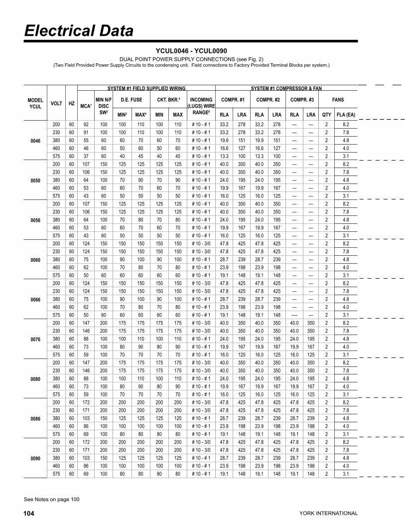
YORK INTERNATIONAL104 YORK INTERNATIONAL 105
FORM 150.63-EG1
MODEL YCUL VOLT HZ
SYSTEM #1 FIELD SUPPLIED WIRING SYSTEM #1 COMPRESSOR & FAN
MCA1MIN N/F
DISC SW2
D.E. FUSE CKT. BKR.5 INCOMING (LUGS) WIRE
RANGE6
COMPR. #1 COMPR. #2 COMPR. #3 FANS
MIN3 MAX4 MIN MAX RLA LRA RLA LRA RLA LRA QTY FLA (EA)
0046
200 60 92 100 100 110 100 110 # 10 - # 1 33.2 278 33.2 278 — — 2 8.2230 60 91 100 100 110 100 110 # 10 - # 1 33.2 278 33.2 278 — — 2 7.8380 60 55 60 60 70 60 70 # 10 - # 1 19.9 151 19.9 151 — — 2 4.8460 60 46 60 50 60 50 60 # 10 - # 1 16.6 127 16.6 127 — — 2 4.0575 60 37 60 40 45 40 45 # 10 - # 1 13.3 100 13.3 100 — — 2 3.1
0050
200 60 107 150 125 125 125 125 # 10 - # 1 40.0 350 40.0 350 — — 2 8.2230 60 106 150 125 125 125 125 # 10 - # 1 40.0 350 40.0 350 — — 2 7.8380 60 64 100 70 90 70 90 # 10 - # 1 24.0 195 24.0 195 — — 2 4.8460 60 53 60 60 70 60 70 # 10 - # 1 19.9 167 19.9 167 — — 2 4.0575 60 43 60 50 50 50 50 # 10 - # 1 16.0 125 16.0 125 — — 2 3.1
0056
200 60 107 150 125 125 125 125 # 10 - # 1 40.0 350 40.0 350 — — 2 8.2230 60 106 150 125 125 125 125 # 10 - # 1 40.0 350 40.0 350 — — 2 7.8380 60 64 100 70 80 70 80 # 10 - # 1 24.0 195 24.0 195 — — 2 4.8460 60 53 60 60 70 60 70 # 10 - # 1 19.9 167 19.9 167 — — 2 4.0575 60 43 60 50 50 50 50 # 10 - # 1 16.0 125 16.0 125 — — 2 3.1
0060
200 60 124 150 150 150 150 150 # 10 - 3/0 47.8 425 47.8 425 — — 2 8.2230 60 124 150 150 150 150 150 # 10 - 3/0 47.8 425 47.8 425 — — 2 7.8380 60 75 100 90 100 90 100 # 10 - # 1 28.7 239 28.7 239 — — 2 4.8460 60 62 100 70 80 70 80 # 10 - # 1 23.9 198 23.9 198 — — 2 4.0575 60 50 60 60 60 60 60 # 10 - # 1 19.1 148 19.1 148 — — 2 3.1
0066
200 60 124 150 150 150 150 150 # 10 - 3/0 47.8 425 47.8 425 — — 2 8.2230 60 124 150 150 150 150 150 # 10 - 3/0 47.8 425 47.8 425 — — 2 7.8380 60 75 100 90 100 90 100 # 10 - # 1 28.7 239 28.7 239 — — 2 4.8460 60 62 100 70 80 70 80 # 10 - # 1 23.9 198 23.9 198 — — 2 4.0575 60 50 60 60 60 60 60 # 10 - # 1 19.1 148 19.1 148 —- — 2 3.1
0076
200 60 147 200 175 175 175 175 # 10 - 3/0 40.0 350 40.0 350 40.0 350 2 8.2230 60 146 200 175 175 175 175 # 10 - 3/0 40.0 350 40.0 350 40.0 350 2 7.8380 60 88 100 100 110 100 110 # 10 - # 1 24.0 195 24.0 195 24.0 195 2 4.8460 60 73 100 80 90 80 90 # 10 - # 1 19.9 167 19.9 167 19.9 167 2 4.0575 60 59 100 70 70 70 70 # 10 - # 1 16.0 125 16.0 125 16.0 125 2 3.1
0080
200 60 147 200 175 175 175 175 # 10 - 3/0 40.0 350 40.0 350 40.0 350 2 8.2230 60 146 200 175 175 175 175 # 10 - 3/0 40.0 350 40.0 350 40.0 350 2 7.8380 60 88 100 100 110 100 110 # 10 - # 1 24.0 195 24.0 195 24.0 195 2 4.8460 60 73 100 80 90 80 90 # 10 - # 1 19.9 167 19.9 167 19.9 167 2 4.0575 60 59 100 70 70 70 70 # 10 - # 1 16.0 125 16.0 125 16.0 125 2 3.1
0086
200 60 172 200 200 200 200 200 # 10 - 3/0 47.8 425 47.8 425 47.8 425 2 8.2230 60 171 200 200 200 200 200 # 10 - 3/0 47.8 425 47.8 425 47.8 425 2 7.8380 60 103 150 125 125 125 125 # 10 - # 1 28.7 239 28.7 239 28.7 239 2 4.8460 60 86 100 100 100 100 100 # 10 - # 1 23.9 198 23.9 198 23.9 198 2 4.0575 60 69 100 80 80 80 80 # 10 - # 1 19.1 148 19.1 148 19.1 148 2 3.1
0090
200 60 172 200 200 200 200 200 # 10 - 3/0 47.8 425 47.8 425 47.8 425 2 8.2230 60 171 200 200 200 200 200 # 10 - 3/0 47.8 425 47.8 425 47.8 425 2 7.8380 60 103 150 125 125 125 125 # 10 - # 1 28.7 239 28.7 239 28.7 239 2 4.8460 60 86 100 100 100 100 100 # 10 - # 1 23.9 198 23.9 198 23.9 198 2 4.0575 60 69 100 80 80 80 80 # 10 - # 1 19.1 148 19.1 148 19.1 148 2 3.1
See Notes on page 100
YCUL0046 - YCUL0090 DUAL POINT POWER SUPPLY CONNECTIONS (see Fig. 2)
(Two Field Provided Power Supply Circuits to the condensing unit. Field connections to Factory Provided Terminal Blocks per system.)
Electrical Data
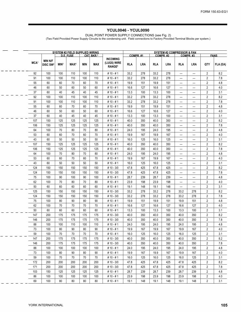
YORK INTERNATIONAL104 YORK INTERNATIONAL 105
FORM 150.63-EG1
SYSTEM #2 FIELD SUPPLIED WIRING SYSTEM #2 COMPRESSOR & FAN
MCA1 MIN N/F DISC SW2
D.E. FUSE CKT. BKR.5
INCOMING (LUGS) WIRE
RANGE6
COMPR. #1 COMPR. #2 COMPR. #3 FANS
MIN3 MAX4 MIN MAX RLA LRA RLA LRA RLA LRA QTY FLA (EA)
92 100 100 110 100 110 # 10 - # 1 33.2 278 33.2 278 — — 2 8.291 100 100 110 100 110 # 10 - # 1 33.2 278 33.2 278 — — 2 7.855 60 60 70 60 70 # 10 - # 1 19.9 151 19.9 151 — — 2 4.846 60 50 60 50 60 # 10 - # 1 16.6 127 16.6 127 — — 2 4.037 60 40 45 40 45 # 10 - # 1 13.3 100 13.3 100 — — 2 3.192 100 100 110 100 110 # 10 - # 1 33.2 278 33.2 278 — — 2 8.291 100 100 110 100 110 # 10 - # 1 33.2 278 33.2 278 — — 2 7.855 60 60 70 60 70 # 10 - # 1 19.9 151 19.9 151 — — 2 4.846 60 50 60 50 60 # 10 - # 1 16.6 127 16.6 127 — — 2 4.037 60 40 45 40 45 # 10 - # 1 13.3 100 13.3 100 — — 2 3.1
107 150 125 125 125 125 # 10 - # 1 40.0 350 40.0 350 — — 2 8.2106 150 125 125 125 125 # 10 - # 1 40.0 350 40.0 350 — — 2 7.864 100 70 80 70 80 # 10 - # 1 24.0 195 24.0 195 — — 2 4.853 60 60 70 60 70 # 10 - # 1 19.9 167 19.9 167 — — 2 4.043 60 50 50 50 50 # 10 - # 1 16.0 125 16.0 125 — — 2 3.1
107 150 125 125 125 125 # 10 - # 1 40.0 350 40.0 350 — — 2 8.2106 150 125 125 125 125 # 10 - # 1 40.0 350 40.0 350 — — 2 7.864 100 70 80 70 80 # 10 - # 1 24.0 195 24.0 195 — — 2 4.853 60 60 70 60 70 # 10 - # 1 19.9 167 19.9 167 — — 2 4.043 60 50 50 50 50 # 10 - # 1 16.0 125 16.0 125 — — 2 3.1
124 150 150 150 150 150 # 10 - 3/0 47.8 425 47.8 425 — — 2 8.2124 150 150 150 150 150 # 10 - 3/0 47.8 425 47.8 425 — — 2 7.875 100 90 100 90 100 # 10 - # 1 28.7 239 28.7 239 — — 2 4.862 100 70 80 70 80 # 10 - # 1 23.9 198 23.9 198 — — 2 4.050 60 60 60 60 60 # 10 - # 1 19.1 148 19.1 148 — — 2 3.1
125 150 150 150 150 150 # 10 - 3/0 33.2 278 33.2 278 33.2 278 2 8.2124 150 150 150 150 150 # 10 - 3/0 33.2 278 33.2 278 33.2 278 2 7.875 100 80 90 80 90 # 10 - # 1 19.9 151 19.9 151 19.9 151 2 4.862 100 70 70 70 70 # 10 - # 1 16.6 127 16.6 127 16.6 127 2 4.050 60 60 60 60 60 # 10 - # 1 13.3 100 13.3 100 13.3 100 2 3.1
147 200 175 175 175 175 # 10 - 3/0 40.0 350 40.0 350 40.0 350 2 8.2146 200 175 175 175 175 # 10 - 3/0 40.0 350 40.0 350 40.0 350 2 7.888 100 100 110 100 110 # 10 - # 1 24.0 195 24.0 195 24.0 195 2 4.873 100 80 90 80 90 # 10 - # 1 19.9 167 19.9 167 19.9 167 2 4.059 100 70 70 70 70 # 10 - # 1 16.0 125 16.0 125 16.0 125 2 3.1
147 200 175 175 175 175 # 10 - 3/0 40.0 350 40.0 350 40.0 350 2 8.2146 200 175 175 175 175 # 10 - 3/0 40.0 350 40.0 350 40.0 350 2 7.888 100 100 100 100 100 # 10 - # 1 24.0 195 24.0 195 24.0 195 2 4.873 100 80 90 80 90 # 10 - # 1 19.9 167 19.9 167 19.9 167 2 4.059 100 70 70 70 70 # 10 - # 1 16.0 125 16.0 125 16.0 125 2 3.1
172 200 200 200 200 200 # 10 - 3/0 47.8 425 47.8 425 47.8 425 2 8.2171 200 200 200 200 200 # 10 - 3/0 47.8 425 47.8 425 47.8 425 2 7.8103 150 125 125 125 125 # 10 - # 1 28.7 239 28.7 239 28.7 239 2 4.886 100 100 100 100 100 # 10 - # 1 23.9 198 23.9 198 23.9 198 2 4.069 100 80 80 80 80 # 10 - # 1 19.1 148 19.1 148 19.1 148 2 3.1
YCUL0046 - YCUL0090 DUAL POINT POWER SUPPLY CONNECTIONS (see Fig. 2)
(Two Field Provided Power Supply Circuits to the condensing unit. Field connections to Factory Provided Terminal Blocks per system.)

YORK INTERNATIONAL106 YORK INTERNATIONAL 107
FORM 150.63-EG1
Electrical Data
See Notes on page 100
YCUL0046 - YCUL0090 SINGLE POINT POWER SUPPLY CONNECTIONS (see Fig. 1)
(One Field Provided Power Supply Circuit to the condensing unit. Field connections to Factory Provided Terminal Block (optional), Non-Fused Disconnect Switch (optional) or Circuit Breaker (optional).)
SINGLE POINT FIELD SUPPLIED WIRING
MODEL YCUL VOLT HZ MCA1 MIN N/F
DISC SW2
D.E. FUSE CKT. BKR.5 INCOMING (LUGS) WIRE RANGE6
MIN3 MAX4 MIN MAX TERMINAL BLOCK (opt)
NF DISC. SWITCH (opt)
CIRCUIT BREAKER
(opt)
0046
200 60 174 200 200 200 200 200 # 10 - 3/0 # 6 - 350 # 3 - 300230 60 173 200 200 200 200 200 # 10 - 3/0 # 6 - 350 # 3 - 300380 60 104 150 110 110 110 110 # 10 - # 1 # 2 - 4/0 # 2 - 4/0460 60 87 100 100 100 100 100 # 10 - # 1 # 14 - 1/0 # 14 - 1/0575 60 69 100 80 80 80 80 # 10 - # 1 # 14 - 1/0 # 14 - 1/0
0050
200 60 190 250 200 225 200 225 # 10 - 300 # 6 - 350 # 3 - 300230 60 188 250 200 225 200 225 # 10 - 300 # 6 - 350 # 3 - 300380 60 113 150 125 125 125 125 # 10 - # 1 # 2 - 4/0 # 2 - 4/0460 60 94 150 100 110 100 110 # 10 - # 1 # 2 - 4/0 # 14 - 1/0575 60 75 100 80 90 80 90 # 10 - # 1 # 14 - 1/0 # 14 - 1/0
0056
200 60 203 250 225 225 225 225 # 10 - 300 # 6 - 350 # 3 - 300230 60 202 250 225 225 225 225 # 10 - 300 # 6 - 350 # 3 - 300380 60 122 150 150 125 150 125 # 10 - 3/0 # 2 - 4/0 # 2 - 4/0460 60 101 150 110 110 110 110 # 10 - # 1 # 2 - 4/0 # 2 - 4/0575 60 81 100 90 90 90 90 # 10 - # 1 # 14 - 1/0 # 14 - 1/0
0060
200 60 221 250 250 250 250 250 # 10 - 300 # 6 - 350 # 6 - 350230 60 219 250 250 250 250 250 # 10 - 300 # 6 - 350 # 6 - 350380 60 132 150 150 150 150 150 # 10 - 3/0 # 2 - 4/0 # 2 - 4/0460 60 110 150 125 125 125 125 # 10 - # 1 # 2 - 4/0 # 2 - 4/0575 60 88 100 100 100 100 100 # 10 - # 1 # 14 - 1/0 # 14 - 1/0
0066
200 60 236 400 250 250 250 250 # 10 - 300 250-500 # 6 - 350230 60 235 400 250 250 250 250 # 10 - 300 250-500 # 6 - 350380 60 142 200 150 150 150 150 # 10 - 3/0 # 6 - 350 # 2 - 4/0460 60 118 150 125 125 125 125 # 10 - 3/0 # 2 - 4/0 # 2 - 4/0575 60 94 150 100 110 100 110 # 10 - # 1 # 2 - 4/0 # 14 - 1/0
0076
200 60 263 400 300 300 300 300 # 4 - 500 250-500 250-500230 60 261 400 300 300 300 300 # 4 - 500 250-500 250-500380 60 157 200 175 175 175 175 # 10 - 3/0 # 6 - 350 # 2 - 4/0460 60 131 150 150 150 150 150 # 10 - 3/0 # 2 - 4/0 # 2 - 4/0575 60 105 150 110 110 110 110 # 10 - # 1 # 2 - 4/0 # 2 - 4/0
0080
200 60 283 400 300 300 300 300 # 4 - 500 250-500 250-500230 60 282 400 300 300 300 300 # 4 - 500 250-500 250-500380 60 170 200 200 200 200 200 # 10 - 3/0 # 6 - 350 # 4 - 300460 60 141 200 150 150 150 150 # 10 - 3/0 # 6 - 350 # 2 - 4/0575 60 113 150 125 125 125 125 # 10 - # 1 # 2 - 4/0 # 2 - 4/0
0086
200 60 309 400 350 350 350 350 # 4 - 500 250-500 250-500230 60 307 400 350 350 350 350 # 4 - 500 250-500 250-500380 60 185 250 200 200 200 200 # 10 - 300 # 6 - 350 # 4 - 300460 60 154 200 175 175 175 175 # 10 - 3/0 # 6 - 350 # 4 - 300575 60 123 150 150 125 150 125 # 10 - 3/0 # 2 - 4/0 # 2 - 4/0
0090
200 60 332 400 350 350 350 350 # 4 - 500 250-500 250-500230 60 330 400 350 350 350 350 # 4 - 500 250-500 250-500380 60 199 250 225 225 225 225 # 10 - 300 # 6 - 350 # 4 - 300460 60 166 200 175 175 175 175 # 10 - 3/0 # 6 - 350 # 4 - 300575 60 132 150 150 150 150 150 # 10 - 3/0 # 2 - 4/0 # 2 - 4/0
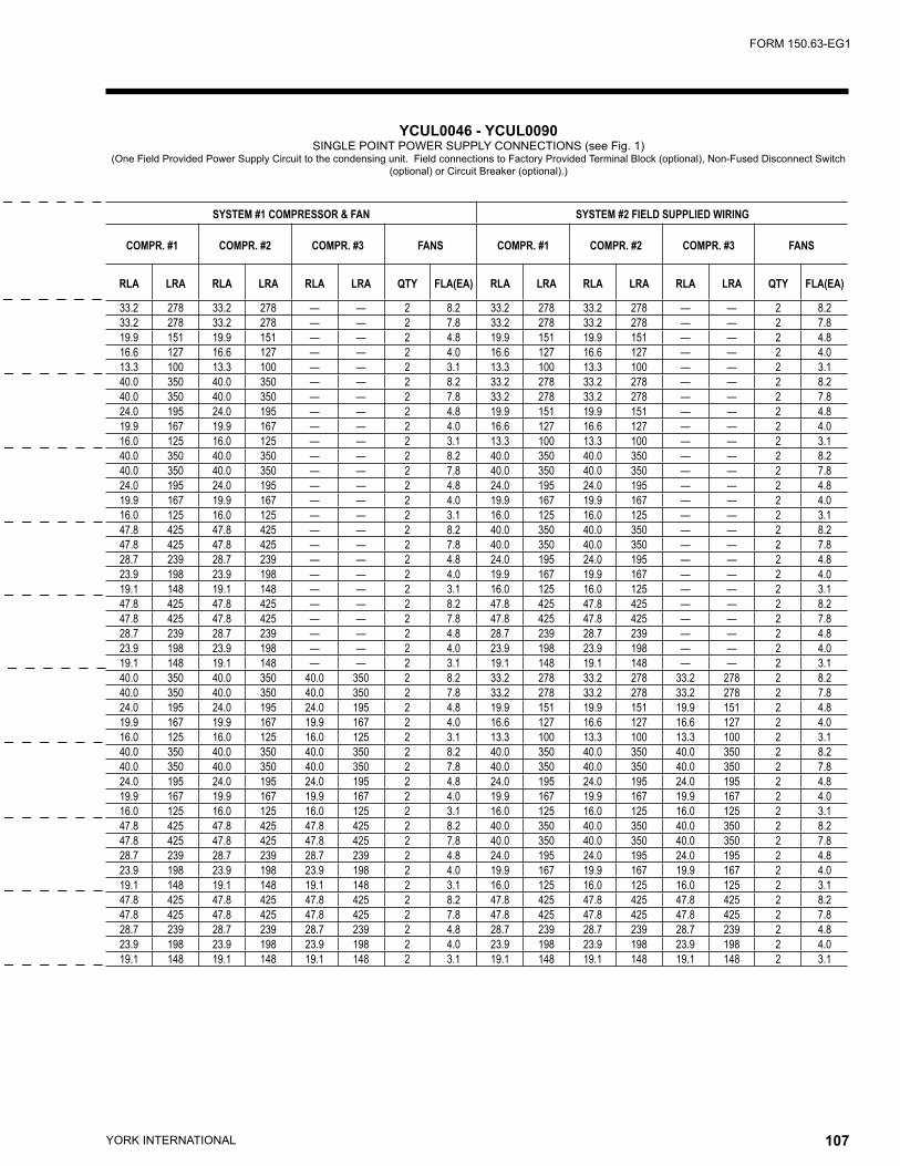
YORK INTERNATIONAL106 YORK INTERNATIONAL 107
FORM 150.63-EG1
SYSTEM #1 COMPRESSOR & FAN SYSTEM #2 FIELD SUPPLIED WIRING
COMPR. #1 COMPR. #2 COMPR. #3 FANS COMPR. #1 COMPR. #2 COMPR. #3 FANS
RLA LRA RLA LRA RLA LRA QTY FLA(EA) RLA LRA RLA LRA RLA LRA QTY FLA(EA)
33.2 278 33.2 278 — — 2 8.2 33.2 278 33.2 278 — — 2 8.233.2 278 33.2 278 — — 2 7.8 33.2 278 33.2 278 — — 2 7.819.9 151 19.9 151 — — 2 4.8 19.9 151 19.9 151 — — 2 4.816.6 127 16.6 127 — — 2 4.0 16.6 127 16.6 127 — — 2 4.013.3 100 13.3 100 — — 2 3.1 13.3 100 13.3 100 — — 2 3.140.0 350 40.0 350 — — 2 8.2 33.2 278 33.2 278 — — 2 8.240.0 350 40.0 350 — — 2 7.8 33.2 278 33.2 278 — — 2 7.824.0 195 24.0 195 — — 2 4.8 19.9 151 19.9 151 — — 2 4.819.9 167 19.9 167 — — 2 4.0 16.6 127 16.6 127 — — 2 4.016.0 125 16.0 125 — — 2 3.1 13.3 100 13.3 100 — — 2 3.140.0 350 40.0 350 — — 2 8.2 40.0 350 40.0 350 — — 2 8.240.0 350 40.0 350 — — 2 7.8 40.0 350 40.0 350 — — 2 7.824.0 195 24.0 195 — — 2 4.8 24.0 195 24.0 195 — — 2 4.819.9 167 19.9 167 — — 2 4.0 19.9 167 19.9 167 — — 2 4.016.0 125 16.0 125 — — 2 3.1 16.0 125 16.0 125 — — 2 3.147.8 425 47.8 425 — — 2 8.2 40.0 350 40.0 350 — — 2 8.247.8 425 47.8 425 — — 2 7.8 40.0 350 40.0 350 — — 2 7.828.7 239 28.7 239 — — 2 4.8 24.0 195 24.0 195 — — 2 4.823.9 198 23.9 198 — — 2 4.0 19.9 167 19.9 167 — — 2 4.019.1 148 19.1 148 — — 2 3.1 16.0 125 16.0 125 — — 2 3.147.8 425 47.8 425 — — 2 8.2 47.8 425 47.8 425 — — 2 8.247.8 425 47.8 425 — — 2 7.8 47.8 425 47.8 425 — — 2 7.828.7 239 28.7 239 — — 2 4.8 28.7 239 28.7 239 — — 2 4.823.9 198 23.9 198 — — 2 4.0 23.9 198 23.9 198 — — 2 4.019.1 148 19.1 148 — — 2 3.1 19.1 148 19.1 148 — — 2 3.140.0 350 40.0 350 40.0 350 2 8.2 33.2 278 33.2 278 33.2 278 2 8.240.0 350 40.0 350 40.0 350 2 7.8 33.2 278 33.2 278 33.2 278 2 7.824.0 195 24.0 195 24.0 195 2 4.8 19.9 151 19.9 151 19.9 151 2 4.819.9 167 19.9 167 19.9 167 2 4.0 16.6 127 16.6 127 16.6 127 2 4.016.0 125 16.0 125 16.0 125 2 3.1 13.3 100 13.3 100 13.3 100 2 3.140.0 350 40.0 350 40.0 350 2 8.2 40.0 350 40.0 350 40.0 350 2 8.240.0 350 40.0 350 40.0 350 2 7.8 40.0 350 40.0 350 40.0 350 2 7.824.0 195 24.0 195 24.0 195 2 4.8 24.0 195 24.0 195 24.0 195 2 4.819.9 167 19.9 167 19.9 167 2 4.0 19.9 167 19.9 167 19.9 167 2 4.016.0 125 16.0 125 16.0 125 2 3.1 16.0 125 16.0 125 16.0 125 2 3.147.8 425 47.8 425 47.8 425 2 8.2 40.0 350 40.0 350 40.0 350 2 8.247.8 425 47.8 425 47.8 425 2 7.8 40.0 350 40.0 350 40.0 350 2 7.828.7 239 28.7 239 28.7 239 2 4.8 24.0 195 24.0 195 24.0 195 2 4.823.9 198 23.9 198 23.9 198 2 4.0 19.9 167 19.9 167 19.9 167 2 4.019.1 148 19.1 148 19.1 148 2 3.1 16.0 125 16.0 125 16.0 125 2 3.147.8 425 47.8 425 47.8 425 2 8.2 47.8 425 47.8 425 47.8 425 2 8.247.8 425 47.8 425 47.8 425 2 7.8 47.8 425 47.8 425 47.8 425 2 7.828.7 239 28.7 239 28.7 239 2 4.8 28.7 239 28.7 239 28.7 239 2 4.823.9 198 23.9 198 23.9 198 2 4.0 23.9 198 23.9 198 23.9 198 2 4.019.1 148 19.1 148 19.1 148 2 3.1 19.1 148 19.1 148 19.1 148 2 3.1
YCUL0046 - YCUL0090 SINGLE POINT POWER SUPPLY CONNECTIONS (see Fig. 1)
(One Field Provided Power Supply Circuit to the condensing unit. Field connections to Factory Provided Terminal Block (optional), Non-Fused Disconnect Switch (optional) or Circuit Breaker (optional).)
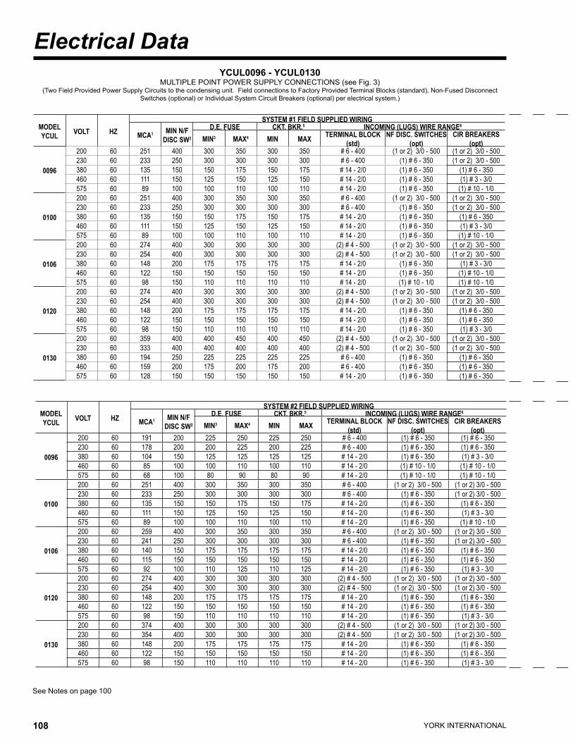
YORK INTERNATIONAL108 YORK INTERNATIONAL 109
FORM 150.63-EG1
Electrical Data
MODEL YCUL VOLT HZ
SYSTEM #1 FIELD SUPPLIED WIRING
MCA1 MIN N/F DISC SW2
D.E. FUSE CKT. BKR.5 INCOMING (LUGS) WIRE RANGE6
MIN3 MAX4 MIN MAX TERMINAL BLOCK (std)
NF DISC. SWITCHES (opt)
CIR BREAKERS (opt)
0096
200 60 251 400 300 350 300 350 # 6 - 400 (1 or 2) 3/0 - 500 (1 or 2) 3/0 - 500230 60 233 250 300 300 300 300 # 6 - 400 (1) # 6 - 350 (1 or 2) 3/0 - 500380 60 135 150 150 175 150 175 # 14 - 2/0 (1) # 6 - 350 (1) # 6 - 350460 60 111 150 125 150 125 150 # 14 - 2/0 (1) # 6 - 350 (1) # 3 - 3/0575 60 89 100 100 110 100 110 # 14 - 2/0 (1) # 6 - 350 (1) # 10 - 1/0
0100
200 60 251 400 300 350 300 350 # 6 - 400 (1 or 2) 3/0 - 500 (1 or 2) 3/0 - 500230 60 233 250 300 300 300 300 # 6 - 400 (1) # 6 - 350 (1 or 2) 3/0 - 500380 60 135 150 150 175 150 175 # 14 - 2/0 (1) # 6 - 350 (1) # 6 - 350460 60 111 150 125 150 125 150 # 14 - 2/0 (1) # 6 - 350 (1) # 3 - 3/0575 60 89 100 100 110 100 110 # 14 - 2/0 (1) # 6 - 350 (1) # 10 - 1/0
0106
200 60 274 400 300 300 300 300 (2) # 4 - 500 (1 or 2) 3/0 - 500 (1 or 2) 3/0 - 500230 60 254 400 300 300 300 300 (2) # 4 - 500 (1 or 2) 3/0 - 500 (1 or 2) 3/0 - 500380 60 148 200 175 175 175 175 # 14 - 2/0 (1) # 6 - 350 (1) # 3 - 3/0460 60 122 150 150 150 150 150 # 14 - 2/0 (1) # 6 - 350 (1) # 10 - 1/0575 60 98 150 110 110 110 110 # 14 - 2/0 (1) # 10 - 1/0 (1) # 10 - 1/0
0120
200 60 274 400 300 300 300 300 (2) # 4 - 500 (1 or 2) 3/0 - 500 (1 or 2) 3/0 - 500230 60 254 400 300 300 300 300 (2) # 4 - 500 (1 or 2) 3/0 - 500 (1 or 2) 3/0 - 500380 60 148 200 175 175 175 175 # 14 - 2/0 (1) # 6 - 350 (1) # 6 - 350460 60 122 150 150 150 150 150 # 14 - 2/0 (1) # 6 - 350 (1) # 6 - 350575 60 98 150 110 110 110 110 # 14 - 2/0 (1) # 6 - 350 (1) # 3 - 3/0
0130
200 60 359 400 400 450 400 450 (2) # 4 - 500 (1 or 2) 3/0 - 500 (1 or 2) 3/0 - 500230 60 333 400 400 400 400 400 (2) # 4 - 500 (1 or 2) 3/0 - 500 (1 or 2) 3/0 - 500380 60 194 250 225 225 225 225 # 6 - 400 (1) # 6 - 350 (1) # 6 - 350460 60 159 200 175 200 175 200 # 6 - 400 (1) # 6 - 350 (1) # 6 - 350575 60 128 150 150 150 150 150 # 14 - 2/0 (1) # 6 - 350 (1) # 6 - 350
MODEL YCUL VOLT HZ
SYSTEM #2 FIELD SUPPLIED WIRING
MCA1 MIN N/F DISC SW2
D.E. FUSE CKT. BKR.5 INCOMING (LUGS) WIRE RANGE6
MIN3 MAX4 MIN MAX TERMINAL BLOCK (std)
NF DISC. SWITCHES (opt)
CIR BREAKERS (opt)
0096
200 60 191 200 225 250 225 250 # 6 - 400 (1) # 6 - 350 (1) # 6 - 350230 60 178 200 200 225 200 225 # 6 - 400 (1) # 6 - 350 (1) # 6 - 350380 60 104 150 125 125 125 125 # 14 - 2/0 (1) # 6 - 350 (1) # 3 - 3/0460 60 85 100 100 110 100 110 # 14 - 2/0 (1) # 10 - 1/0 (1) # 10 - 1/0575 60 68 100 80 90 80 90 # 14 - 2/0 (1) # 10 - 1/0 (1) # 10 - 1/0
0100
200 60 251 400 300 350 300 350 # 6 - 400 (1 or 2) 3/0 - 500 (1 or 2) 3/0 - 500230 60 233 250 300 300 300 300 # 6 - 400 (1) # 6 - 350 (1 or 2) 3/0 - 500380 60 135 150 150 175 150 175 # 14 - 2/0 (1) # 6 - 350 (1) # 6 - 350460 60 111 150 125 150 125 150 # 14 - 2/0 (1) # 6 - 350 (1) # 3 - 3/0575 60 89 100 100 110 100 110 # 14 - 2/0 (1) # 6 - 350 (1) # 10 - 1/0
0106
200 60 259 400 300 350 300 350 # 6 - 400 (1 or 2) 3/0 - 500 (1 or 2) 3/0 - 500230 60 241 250 300 300 300 300 # 6 - 400 (1) # 6 - 350 (1 or 2) 3/0 - 500380 60 140 150 175 175 175 175 # 14 - 2/0 (1) # 6 - 350 (1) # 6 - 350460 60 115 150 150 150 150 150 # 14 - 2/0 (1) # 6 - 350 (1) # 6 - 350575 60 92 100 110 125 110 125 # 14 - 2/0 (1) # 6 - 350 (1) # 3 - 3/0
0120
200 60 274 400 300 300 300 300 (2) # 4 - 500 (1 or 2) 3/0 - 500 (1 or 2) 3/0 - 500230 60 254 400 300 300 300 300 (2) # 4 - 500 (1 or 2) 3/0 - 500 (1 or 2) 3/0 - 500380 60 148 200 175 175 175 175 # 14 - 2/0 (1) # 6 - 350 (1) # 6 - 350460 60 122 150 150 150 150 150 # 14 - 2/0 (1) # 6 - 350 (1) # 6 - 350575 60 98 150 110 110 110 110 # 14 - 2/0 (1) # 6 - 350 (1) # 3 - 3/0
0130
200 60 374 400 300 300 300 300 (2) # 4 - 500 (1 or 2) 3/0 - 500 (1 or 2) 3/0 - 500230 60 354 400 300 300 300 300 (2) # 4 - 500 (1 or 2) 3/0 - 500 (1 or 2) 3/0 - 500380 60 148 200 175 175 175 175 # 14 - 2/0 (1) # 6 - 350 (1) # 6 - 350460 60 122 150 150 150 150 150 # 14 - 2/0 (1) # 6 - 350 (1) # 6 - 350575 60 98 150 110 110 110 110 # 14 - 2/0 (1) # 6 - 350 (1) # 3 - 3/0
YCUL0096 - YCUL0130 MULTIPLE POINT POWER SUPPLY CONNECTIONS (see Fig. 3)
(Two Field Provided Power Supply Circuits to the condensing unit. Field connections to Factory Provided Terminal Blocks (standard), Non-Fused Disconnect Switches (optional) or Individual System Circuit Breakers (optional) per electrical system.)
See Notes on page 100
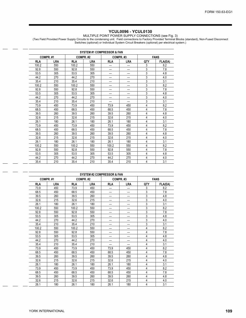
YORK INTERNATIONAL108 YORK INTERNATIONAL 109
FORM 150.63-EG1
SYSTEM #1 COMPRESSOR & FANCOMPR. #1 COMPR. #2 COMPR. #3 FANS
RLA LRA RLA LRA RLA LRA QTY FLA(EA)100.2 550 100.2 550 — — 3 8.292.8 550 92.8 550 — — 3 7.853.5 305 53.5 305 — — 3 4.844.2 270 44.2 270 — — 3 4.035.4 210 35.4 210 — — 3 3.1
100.2 550 100.2 550 — — 3 8.292.8 550 92.8 550 — — 3 7.853.5 305 53.5 305 — — 3 4.844.2 270 44.2 270 — — 3 4.035.4 210 35.4 210 — — 3 3.173.9 450 73.9 450 73.9 450 4 8.268.5 450 68.5 450 68.5 450 4 7.839.5 260 39.5 260 39.5 260 4 4.832.6 215 32.6 215 32.6 215 4 4.026.1 180 26.1 180 26.1 180 4 3.173.9 450 73.9 450 73.9 450 4 8.268.5 450 68.5 450 68.5 450 4 7.839.5 260 39.5 260 39.5 260 4 4.832.6 215 32.6 215 32.6 215 4 4.026.1 180 26.1 180 26.1 180 4 3.1
100.2 550 100.2 550 100.2 550 4 8.292.8 550 92.8 550 92.8 550 4 7.853.5 305 53.5 305 53.5 305 4 4.844.2 270 44.2 270 44.2 270 4 4.035.4 210 35.4 210 35.4 210 4 3.1
SYSTEM #2 COMPRESSOR & FANCOMPR. #1 COMPR. #2 COMPR. #3 FANS
RLA LRA RLA LRA RLA LRA QTY FLA(EA)73.9 450 73.9 450 — — 3 8.268.5 450 68.5 450 — — 3 7.839.5 260 39.5 260 — — 3 4.832.6 215 32.6 215 — — 3 4.026.1 180 26.1 180 — — 3 3.1
100.2 550 100.2 550 — — 3 8.292.8 550 92.8 550 — — 3 7.853.5 305 53.5 305 — — 3 4.844.2 270 44.2 270 — — 3 4.035.4 210 35.4 210 — — 3 3.1
100.2 550 100.2 550 — — 4 8.292.8 550 92.8 550 — — 4 7.853.5 305 53.5 305 — — 4 4.844.2 270 44.2 270 — — 4 4.035.4 210 35.4 210 — — 4 3.173.9 450 73.9 450 73.9 450 4 8.268.5 450 68.5 450 68.5 450 4 7.839.5 260 39.5 260 39.5 260 4 4.832.6 215 32.6 215 32.6 215 4 4.026.1 180 26.1 180 26.1 180 4 3.173.9 450 73.9 450 73.9 450 4 8.268.5 450 68.5 450 68.5 450 4 7.839.5 260 39.5 260 39.5 260 4 4.832.6 215 32.6 215 32.6 215 4 4.026.1 180 26.1 180 26.1 180 4 3.1
YCUL0096 - YCUL0130 MULTIPLE POINT POWER SUPPLY CONNECTIONS (see Fig. 3)
(Two Field Provided Power Supply Circuits to the condensing unit. Field connections to Factory Provided Terminal Blocks (standard), Non-Fused Disconnect Switches (optional) or Individual System Circuit Breakers (optional) per electrical system.)
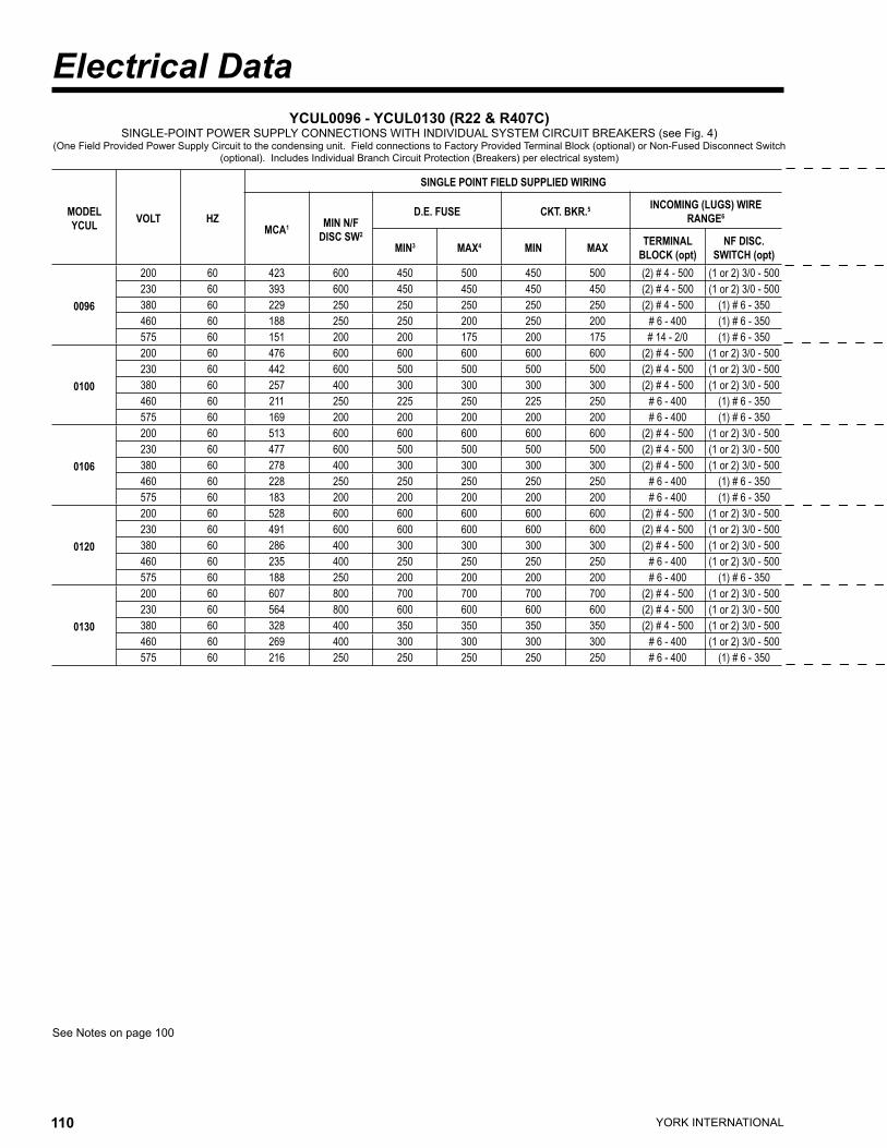
YORK INTERNATIONAL110 YORK INTERNATIONAL 111
FORM 150.63-EG1
Electrical Data
See Notes on page 100
YCUL0096 - YCUL0130 (R22 & R407C)SINGLE-POINT POWER SUPPLY CONNECTIONS WITH INDIVIDUAL SYSTEM CIRCUIT BREAKERS (see Fig. 4)
(One Field Provided Power Supply Circuit to the condensing unit. Field connections to Factory Provided Terminal Block (optional) or Non-Fused Disconnect Switch (optional). Includes Individual Branch Circuit Protection (Breakers) per electrical system)
MODEL YCUL VOLT HZ
SINGLE POINT FIELD SUPPLIED WIRING
MCA1 MIN N/F DISC SW2
D.E. FUSE CKT. BKR.5 INCOMING (LUGS) WIRE RANGE6
MIN3 MAX4 MIN MAX TERMINAL BLOCK (opt)
NF DISC. SWITCH (opt)
0096
200 60 423 600 450 500 450 500 (2) # 4 - 500 (1 or 2) 3/0 - 500230 60 393 600 450 450 450 450 (2) # 4 - 500 (1 or 2) 3/0 - 500380 60 229 250 250 250 250 250 (2) # 4 - 500 (1) # 6 - 350460 60 188 250 250 200 250 200 # 6 - 400 (1) # 6 - 350575 60 151 200 200 175 200 175 # 14 - 2/0 (1) # 6 - 350
0100
200 60 476 600 600 600 600 600 (2) # 4 - 500 (1 or 2) 3/0 - 500230 60 442 600 500 500 500 500 (2) # 4 - 500 (1 or 2) 3/0 - 500380 60 257 400 300 300 300 300 (2) # 4 - 500 (1 or 2) 3/0 - 500460 60 211 250 225 250 225 250 # 6 - 400 (1) # 6 - 350575 60 169 200 200 200 200 200 # 6 - 400 (1) # 6 - 350
0106
200 60 513 600 600 600 600 600 (2) # 4 - 500 (1 or 2) 3/0 - 500230 60 477 600 500 500 500 500 (2) # 4 - 500 (1 or 2) 3/0 - 500380 60 278 400 300 300 300 300 (2) # 4 - 500 (1 or 2) 3/0 - 500460 60 228 250 250 250 250 250 # 6 - 400 (1) # 6 - 350575 60 183 200 200 200 200 200 # 6 - 400 (1) # 6 - 350
0120
200 60 528 600 600 600 600 600 (2) # 4 - 500 (1 or 2) 3/0 - 500230 60 491 600 600 600 600 600 (2) # 4 - 500 (1 or 2) 3/0 - 500380 60 286 400 300 300 300 300 (2) # 4 - 500 (1 or 2) 3/0 - 500460 60 235 400 250 250 250 250 # 6 - 400 (1 or 2) 3/0 - 500575 60 188 250 200 200 200 200 # 6 - 400 (1) # 6 - 350
0130
200 60 607 800 700 700 700 700 (2) # 4 - 500 (1 or 2) 3/0 - 500230 60 564 800 600 600 600 600 (2) # 4 - 500 (1 or 2) 3/0 - 500380 60 328 400 350 350 350 350 (2) # 4 - 500 (1 or 2) 3/0 - 500460 60 269 400 300 300 300 300 # 6 - 400 (1 or 2) 3/0 - 500575 60 216 250 250 250 250 250 # 6 - 400 (1) # 6 - 350
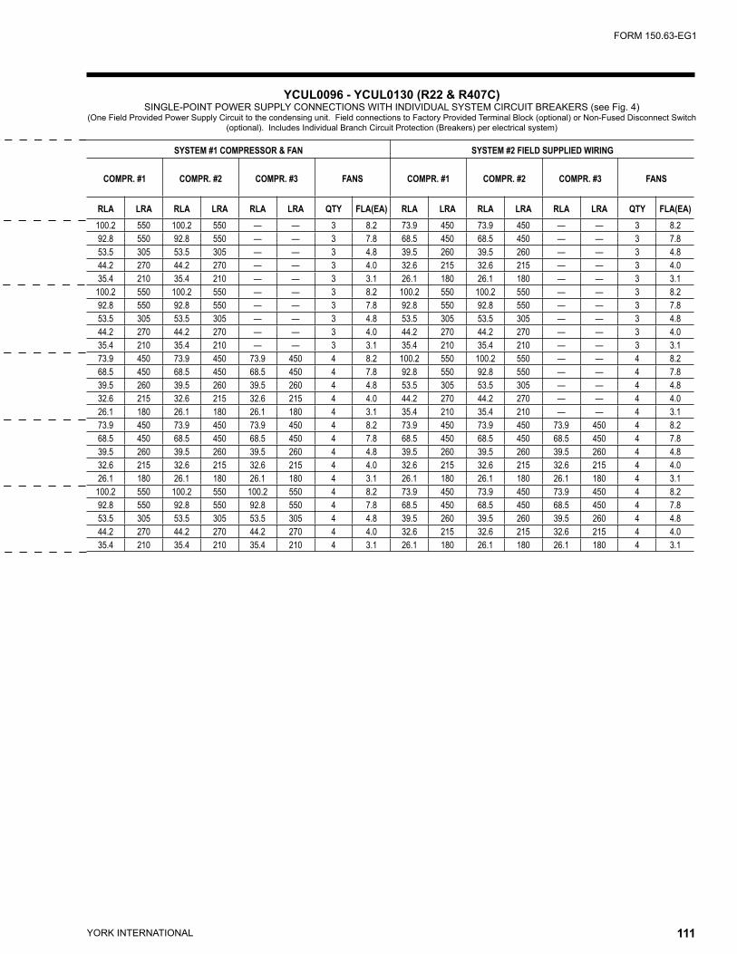
YORK INTERNATIONAL110 YORK INTERNATIONAL 111
FORM 150.63-EG1
SYSTEM #1 COMPRESSOR & FAN SYSTEM #2 FIELD SUPPLIED WIRING
COMPR. #1 COMPR. #2 COMPR. #3 FANS COMPR. #1 COMPR. #2 COMPR. #3 FANS
RLA LRA RLA LRA RLA LRA QTY FLA(EA) RLA LRA RLA LRA RLA LRA QTY FLA(EA)100.2 550 100.2 550 — — 3 8.2 73.9 450 73.9 450 — — 3 8.292.8 550 92.8 550 — — 3 7.8 68.5 450 68.5 450 — — 3 7.853.5 305 53.5 305 — — 3 4.8 39.5 260 39.5 260 — — 3 4.844.2 270 44.2 270 — — 3 4.0 32.6 215 32.6 215 — — 3 4.035.4 210 35.4 210 — — 3 3.1 26.1 180 26.1 180 — — 3 3.1
100.2 550 100.2 550 — — 3 8.2 100.2 550 100.2 550 — — 3 8.292.8 550 92.8 550 — — 3 7.8 92.8 550 92.8 550 — — 3 7.853.5 305 53.5 305 — — 3 4.8 53.5 305 53.5 305 — — 3 4.844.2 270 44.2 270 — — 3 4.0 44.2 270 44.2 270 — — 3 4.035.4 210 35.4 210 — — 3 3.1 35.4 210 35.4 210 — — 3 3.173.9 450 73.9 450 73.9 450 4 8.2 100.2 550 100.2 550 — — 4 8.268.5 450 68.5 450 68.5 450 4 7.8 92.8 550 92.8 550 — — 4 7.839.5 260 39.5 260 39.5 260 4 4.8 53.5 305 53.5 305 — — 4 4.832.6 215 32.6 215 32.6 215 4 4.0 44.2 270 44.2 270 — — 4 4.026.1 180 26.1 180 26.1 180 4 3.1 35.4 210 35.4 210 — — 4 3.173.9 450 73.9 450 73.9 450 4 8.2 73.9 450 73.9 450 73.9 450 4 8.268.5 450 68.5 450 68.5 450 4 7.8 68.5 450 68.5 450 68.5 450 4 7.839.5 260 39.5 260 39.5 260 4 4.8 39.5 260 39.5 260 39.5 260 4 4.832.6 215 32.6 215 32.6 215 4 4.0 32.6 215 32.6 215 32.6 215 4 4.026.1 180 26.1 180 26.1 180 4 3.1 26.1 180 26.1 180 26.1 180 4 3.1
100.2 550 100.2 550 100.2 550 4 8.2 73.9 450 73.9 450 73.9 450 4 8.292.8 550 92.8 550 92.8 550 4 7.8 68.5 450 68.5 450 68.5 450 4 7.853.5 305 53.5 305 53.5 305 4 4.8 39.5 260 39.5 260 39.5 260 4 4.844.2 270 44.2 270 44.2 270 4 4.0 32.6 215 32.6 215 32.6 215 4 4.035.4 210 35.4 210 35.4 210 4 3.1 26.1 180 26.1 180 26.1 180 4 3.1
YCUL0096 - YCUL0130 (R22 & R407C)SINGLE-POINT POWER SUPPLY CONNECTIONS WITH INDIVIDUAL SYSTEM CIRCUIT BREAKERS (see Fig. 4)
(One Field Provided Power Supply Circuit to the condensing unit. Field connections to Factory Provided Terminal Block (optional) or Non-Fused Disconnect Switch (optional). Includes Individual Branch Circuit Protection (Breakers) per electrical system)
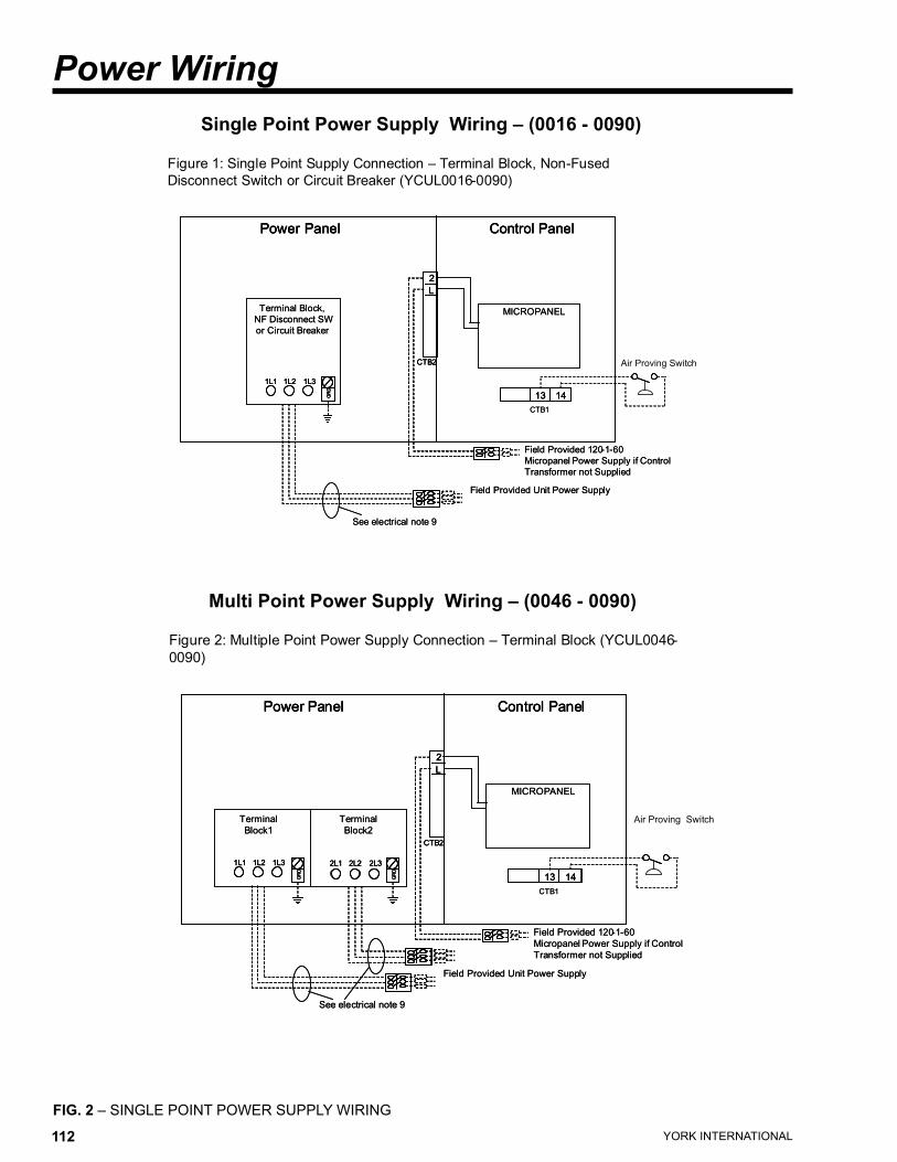
YORK INTERNATIONAL112 YORK INTERNATIONAL 113
FORM 150.63-EG1
Power Wiring
FIG. 2 – SINGLE POINT POWER SUPPLY WIRING
Single Point Power Supply Wiring – (0016 - 0090)
������������������������������������������ ��������������������������
����������������������������������������������������
����������� �������������
���������������
����������������
������������������
��� ��� ���
���
����������
�
�
����
�� ��
����
��������������������������������
������������������������
�����������������������������������
������������������������
���������������������
����������� ������������������������ �������������
���������������
����������������
������������������
��� ��� ������ ��� ���
���
���
���
����������
�
�
����
�
�
����
�� ���� ��
����
��������������������������������
������������������������
�����������������������������������
������������������������
������������������
���������������������
Multi Point Power Supply Wiring – (0046 - 0090)
�������������������������������������������������� �������������������������
�����
����������� �������������
��������
������
��������
������
��� ��� ��� ��� ��� ���
���
���
����������
�
�
����
�� ��
����
��������������������������������
������������������������
�����������������������������������
������������������������
���������������������
����������� ������������������������ �������������
��������
������
��������
������
��� ��� ������ ��� ��� ��� ��� ������ ��� ���
���
���
���
���
���
���
����������
�
�
����
�
�
����
�� ���� ��
����
��������������������������������
������������������������
�����������������������������������
������������������������
�������������������
���������������������
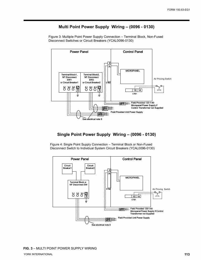
YORK INTERNATIONAL112 YORK INTERNATIONAL 113
FORM 150.63-EG1
�������������������������������������������������� ��������������������������
�������������������������������������������������������
����������� �������������
����������������
��������������
���
�������������������
����������������
��������������
���
�������������������
��� ��� ��� ��� ��� ���
���
���
����������
�
�
����
�� ��
����
��������������������������������
������������������������
���������������������������
��������������������������������
���������������������
����������� ������������������������ �������������
����������������
��������������
���
�������������������
����������������
��������������
���
�������������������
��� ��� ������ ��� ��� ��� ��� ������ ��� ���
���
���
���
���
���
���
����������
�
�
����
�
�
����
�� ���� ��
����
��������������������������������
������������������������
���������������������������
��������������������������������
������������������
���������������������
Multi Point Power Supply Wiring – (0096 - 0130)
FIG. 3 – MULTI POINT POWER SUPPLY WIRING
������������������������������������������ ����������������������������
�����������������������������������������������������������������������
����������� �������������
�����������������
����������������
��� ��� ���
���
����������
�
�
����
�� ��
����
��������������������������������
������������������������
�����������������������������������
������������������������
���������������������
�������
��������
�������
��������
����������� ������������������������ �������������
�����������������
����������������
��� ��� ������ ��� ���
���
���
���
����������
�
�
����
�
�
����
�� ���� ��
����
��������������������������������
������������������������
�����������������������������������
������������������������
�������������������
���������������������
�������
��������
�������
��������
Single Point Power Supply Wiring – (0096 - 0130)
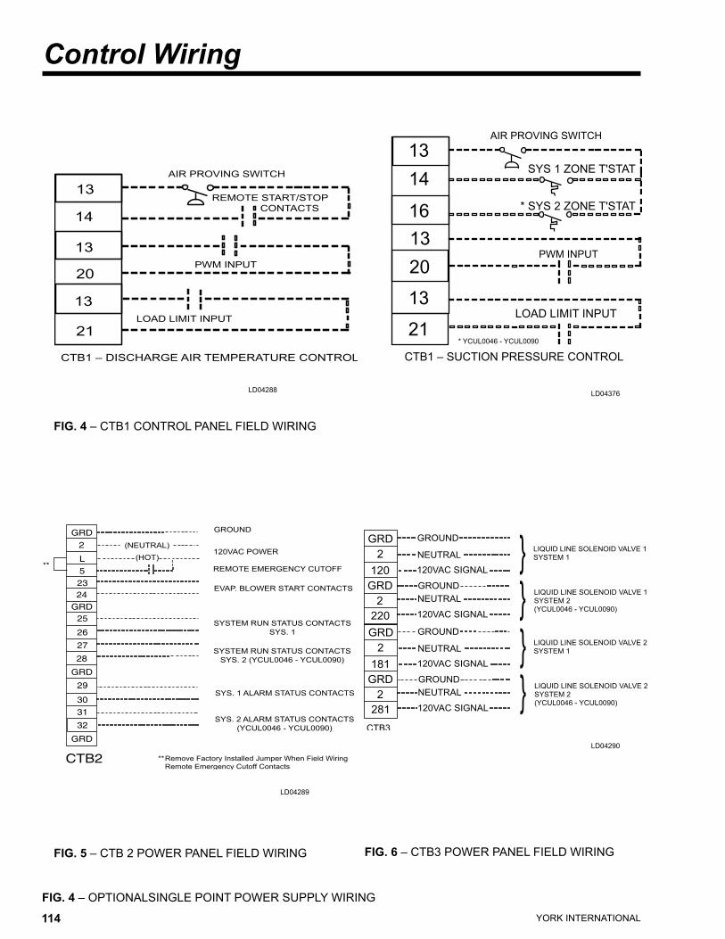
YORK INTERNATIONAL114 YORK INTERNATIONAL 115
FORM 150.63-EG1
FIG. 4 – OPTIONALSINGLE POINT POWER SUPPLY WIRING
������
���������
�����������������
��������������������������
������
��������������������������
����������������������������
����������������������������
�����������������������
���������������������������
����������������������������
���������������������
����������������������������������������������������
� ��������������������������������
��
�������������������������������
��
��
��
��
��
��
������������������
���������
�����������������
����������������
��
�������������������
����������������������������������������
��
��
��
��
��
��
������������������
�����������������
������������������������
���������
����������������
������
�������
����������������
�
���
���
�
���
������
�������
�������������
����
����������������������������
��������
����������������������������
��������
���������������������
��
������
�������
����������������
�
���
���
�
���
������
�������
�������������
����������������������������
��������
����������������������������
��������
���������������������
��
Control Wiring
LD04289
LD04288
LD04290
FIG. 4 – CTB1 CONTROL PANEL FIELD WIRING
LD04376
FIG. 5 – CTB 2 POWER PANEL FIELD WIRING FIG. 6 – CTB3 POWER PANEL FIELD WIRING
* YCUL0046 - YCUL0090
YORK INTERNATIONAL114 YORK INTERNATIONAL 115
FORM 150.63-EG1
Intentionally left blank
YORK INTERNATIONAL116 YORK INTERNATIONAL 117
FORM 150.63-EG1
UNIT LOCATION
The YCUL Condensing Units are designed for outdoor installation. When selecting a site for installation, be guided by the following conditions:
1.For outdoor locations of the unit, select a place having an adequate supply of fresh air for the condenser.
2. Avoid locations beneath windows or between struc-tures where normal operating sounds may be objec-tionable.
3. Installation sites may be either on a roof, or at ground level. (See FOUNDATION.)
4. The condenser fans are the propeller-type, and are not recommended for use with duct work in the con-denser air stream.
5. When it is desirable to surround the unit(s), it is rec-ommended that the screening be able to pass the required chiller CFM without exceeding 0.1" of water external static pressure.
6. Protection against corrosive environments is available by supplying the units with either copper fin, cured phenolic, or epoxy coating on the condenser coils. The phenolic or epoxy coils should be offered with any units being installed at the seashore or where salt spray may hit the unit.
In installations where winter operation is intended and snow accumulations are expected, additional height must be provided to ensure normal condenser air flow.
Recommended clearances for units are given in DIMEN-SIONS. When the available space is less, the unit(s) must be equipped with the discharge pressure trans-ducer option to permit high pressure unloading in the event that air recirculation were to occur.
FOUNDATION
The unit should be mounted on a flat and level founda-tion, ground or roof, capable of supporting the entire operating weight of the equipment. Operating weights are given in the PHYSICAL DATA tables.
ROOF LOCATIONS – Choose a spot with adequate structural strength to safely support the entire weight of the unit and service personnel. Care must be taken not to damage the roof during installation. If the roof is “bonded”, consult the building contractor or architect for special installation requirements. Roof installations should incorporate the use of spring-type isolators to minimize the transmission of vibration into the building structure.
Application DataGROUND LEVEL INSTALLATIONS – It is important that the units be installed on a substantial base that will not settle, causing strain on the refrigerant lines and resulting in possible leaks. A one-piece concrete slab with footers extending below the frost line is highly rec-ommended. Additionally, the slab should not be tied to the main building foundation as noises will telegraph.
Mounting holes (11/16" diameter) are provided in the steel channel for bolting the unit to its foundation. See DIMENSIONS.
For ground level installations, precautions should be taken to protect the unit from tampering by or injury to unauthorized persons. Screws on access panels will pre-vent casual tampering; however, further safety precau-tions, such as unit enclosure options, a fenced-in enclo-sure, or locking devices on the panels may be advisable. Check local authorities for safety regulations.
REFRIGERANT PIPING
When sizing refrigerant pipe for split system air condi-tioning, consideration must be given to the: (1) Suction line pressure drop due to friction, (2) Liquid line pres-sure drop due to friction, (3) Suction line velocity for oil return, and (4) Liquid line pressure drop due to vertical rise. Refer to DESIGN PARAMETERS for friction losses for both the suction and liquid lines for the condensing unit.
On a system where the evaporator blower is located below the condensing unit, the suction line must be sized for both pressure drop and oil return.
When the condensing unit is located below the evapora-tor blower, the liquid line must be designed for pressure drop due to friction loss and vertical rise. If the pressure drop due to vertical rise and friction loss exceeds 30 psi, some refrigerant will flash before it reaches the thermal expansion valve.
All horizontal suction lines should be pitched at least 1/4 inch per foot in the direction of the refrigerant flow to aid the return of oil to the compressor. All suction lines with a vertical rise exceeding 3 feet should have a ‘P’ trap at the bottom and the top to facilitate oil return. Suction lines with a vertical rise exceeding 25 feet should be trapped every 15 feet to provide drain points for the oil when the circuit is deactivated. When the circuit is reactivated, oil will return to the compressor more quickly and in smaller slugs.
For more details, refer to ASHRAE Refrigeration Hand-book, System Practices for Halocarbon Refrigerants.
YORK INTERNATIONAL116 YORK INTERNATIONAL 117
FORM 150.63-EG1
Guide SpecificationsPART 1 – GENERAL
1.01 SCOPE
A. The requirements of the General Conditions, Supplementary Conditions, Division 1, and Draw-ings apply to all Work herein.
B. Provide Microprocessor controlled, multiple-scroll compressor, air-cooled, condensing units of the scheduled capacities as shown and indicated on the Drawings, including but not limited to:
1. Condensing Unit package 2. Electrical power and control connections 3. DX Central Station Air Handling connections
1.02 QUALITY ASSURANCE
A. Products shall be Designed, Tested, and installed in compliance with applicable sections of the following Standards and Codes:
1. ANSI/ASHRAE Standard 15 – Safety Code for Mechanical Refrigeration
2. ASHRAE 90.1 - Energy efficiency compli- ance.
3. ANSI/NFPA Standard 70 – National Electrical Code (N.E.C.). 4. Conform to Intertek Testing Services, formerly ETL, for construction of condensing units and
provide E.T.L./c E.T.L. Listing label. 5. Manufactured in facility registered to ISO 9002.
B. Factory Test: Condensing Unit shall be pressure-tested, evacuated and given a nitrogen holding charge and an initial oil charge, and shall be fac-tory operational run tested to assure each control device operates properly.
C. Warranty: Manufacturer shall Warrant all equipment and material of its manufacture against defects in workmanship and material for a period of one year from date of initial start-up or eighteen (18) months from date of shipment, whichever occurs first.
1.03 DELIVERY AND HANDLING
A. Unit shall be delivered to job site fully assembled, and given nitrogen holding charge and a full oil charge by the Manufacturer. (R-22 or HFC-407C supplied by others).
B. Unit shall be stored and handled per Manufacturer’s
instructions.
PART 2 - PRODUCTS
2.01 CONDENSING UNITS MATERIALS AND COMPONENTS
A. General: Install and commission, as shown on the schedules and plans, factory assembled, charged, and tested air cooled scroll compressor condensing unit as specified herein. Condensing Unit shall be designed, selected, and constructed using a refrig-erant with Flammability rating of “1”, as defined by ANSI/ASHRAE STANDARD - 34 Number Desig-nation and Safety Classification of Refrigerants. Condensing Unit shall include, but is not limited to: a system with a single refrigerant circuit 35 tons (123kW) and below, and not less than two refriger-ant circuits above 35 tons (123kW), scroll compres-sors, air-cooled condenser, refrigerant, lubrication system, interconnecting wiring, safety and operating controls including capacity controller, control center, motor starting components, and special features as specified herein or required for safe, automatic operation.
B. Cabinet: External structural members shall be con-structed of heavy gauge, galvanized steel coated with baked on powder paint which, when subject to ASTM B117, 500 hour, 5% salt spray test, yields minimum ASTM 1654 rating of “6”
2.02 COMPRESSORS
Compressors: Shall be hermetic, scroll-type, includ-ing:
1 Compliant design for axial and radial sealing.2. Refrigerant flow through the compressor with
100% suction cooled motor.3. Large suction side free volume and oil sump to
provide liquid handling capability.4. Compressor crankcase heaters to provide extra
liquid migration protection.5. Annular discharge check valve and reverse vent
assembly to provide low pressure drop, silent shutdown and reverse rotation protection.
6. Initial Oil charge.7. Oil Level sightglass.8. Vibration isolator mounts for compressors.9. Brazed-type connections for fully hermetic
refrigerant circuits.
YORK INTERNATIONAL118 YORK INTERNATIONAL 119
FORM 150.63-EG1
2.03 REFRIGERANT CIRCUIT
One (YCUL0016-0040) or two (YCUL0046-0130) inde-pendent refrigerant circuits will be furnished on each unit. All unit piping will be copper, with brazed joints. The liquid line will include a field connection shutoff valve with charging port located on each condenser circuit. Suc-tion line connections are provided on each refrigeration circuit. Filter drier and sight glass are shipped loose for field installation on each refrigerant circuit.
All expansion valves and liquid line solenoid valves and refrigerant field piping are supplied by others.
2.04 HEAT EXCHANGERS
A. Air Cooled Condenser:
1. Coils: Internally enhanced, seamless copper tubes, mechanically expanded into aluminum alloy fins with full height collars. Subcooling coil an integral part of condenser. Design working pressure shall be 450 psig (31 bar).
2. Fans: Shall be dynamically and statically balanced, direct drive, corrosion resistant glass fiber reinforced composite blades molded into low noise, full airfoil cross section, providing vertical air discharge from extended orifices for efficiency and low sound. Each fan in its own compartment to prevent cross flow during fan cycling. Guards of heavy gauge, PVC (polyvinyl chloride) coated or galvanized steel.
3. Fan Motors: High efficiency, direct drive, 6 pole, 3 phase, insulation class “F”, current protected, Totally Enclosed Air-Over (TEAO), rigid mounted, with double sealed, permanently lubricated, ball bearings.
2.05 CONTROLS
A. General: Automatic start, stop, operating, and protection sequences across the range of scheduled conditions and transients.
B. Microprocessor Enclosure: Rain and dust tight NEMA 3R/12 (IP55) powder painted steel cabinet with hinged, latched, and gasket sealed door.
C. Microprocessor Control Center:
1. Condensing Unit control can be set for Dis-charge Air Temperature Control or for Suction Pressure Control. (Note: Suction Pressure Control requires optional Suction Pressure Transducers on Models YCUL0016-0066.)
2. Automatic control of compressor start/stop, anti-coincidence and anti-recycle timers,
automatic pump-down shut-down, condenser fans, unit alarm contacts, and condensing unit operation from 0°F to 125°F (-18°C to 52°C) ambient. Automatic reset to normal chiller operation after power failure.
3. Discharge air temperature reset via a Pulse Width Modulated (PWM) input signal or up to two steps of demand (load) limiting.
4. Software stored in non-volatile memory, with programmed set-points retained in lithium battery backed real time clock (RTC) memory for minimum 5 years.
5. Forty character liquid crystal display, descrip-tions in English (or Spanish, French, Italian, or German), numeric data in English (or Metric) units. Sealed keypad with sections for Set-points, Display/Print, Entry, Unit Options & clock, and On/Off Switch.
6. Programmable Set-points (within Manufacturer limits): display language; suction pressure setting and control range, remote reset tem-perature range, set daily schedule/holiday for start/stop, manual override for servicing, low and high ambient cutouts, number of compressors, low suction pressure cutout, high discharge pressure cutout, anti-recycle timer (compressor start cycle time), and anti-coincident timer (delay compressor starts).
7. Display Data: Suction temperatures (optional), low ambient temperature cutout setting, outdoor air temperature, English or metric data, suction pressure cutout setting, each system suction pressure (optional on YCUL0016-0066 models), discharge pressure (optional), dis-charge air reset via a YORK ISN DDC or Building Automation System (by others) via PWM input as standard or a 4-20milliamp or 0-10 VDC input or contact closure with optional BAS interface, anti-recycle timer status for each compressor, anti-coincident system start timer condition, compressor run status, no cooling load condition, day, date and time, daily start/stop times, holiday status, automatic or manual system lead/lag control (when controlling based on Discharge Air Temperature only), automatic lead/lag of compressors within a system, compressor starts/operating hours (each), status of hot gas valves, and fan operation, run permissive status, number of compressors running, liquid solenoid valve status, load & unload timer status.
8. System Safeties: Shall cause individual com-pressor systems to perform auto shut down; manual reset required after the third trip in 90 minutes. Includes: high discharge pressure,
Guide Specifications
YORK INTERNATIONAL118 YORK INTERNATIONAL 119
FORM 150.63-EG1
low suction pressure, high pressure switch, and motor protector. Compressor motor protector shall protect against damage due to high input current or thermal overload of windings.
9. Unit Safeties: Shall be automatic reset and cause compressors to shut down if low ambient, or under voltage.
10. Alarm Contacts: Low ambient, low voltage, low battery, and (per compressor circuit): high discharge pressure, and low suction pressure.
D. Manufacturer shall provide any controls not listed above, necessary for automatic condensing unit operation. Mechanical Contractor shall provide field control wiring necessary to interface sensors to the condensing unit control system.
2.06 POWER CONNECTION AND DISTRIBUTION
A. Power Panels:
1. NEMA 3R/12 (IP55) rain/dust tight, powder painted steel cabinets with hinged, latched, and gasket sealed outer doors. Provide main power connection(s), control power connections, compressor and fan motor start contactors, current overloads, and factory wiring.
2. Power supply shall enter unit at a single location, be 3 phase of scheduled voltage, and connect to individual terminal blocks per compressor. Separate disconnecting means and/or external branch circuit protection (by Contractor) required per applicable local or national codes.
B. Exposed compressor, control and fan motor power wiring shall be routed through liquid tight conduit.
2.07 ACCESSORIES AND OPTIONS
Some accessories and options supercede standard product features. Your YORK representative will be pleased to provide assistance.
A. Microprocessor controlled, Factory installed Across-the-Line type compressor motor starters as standard.
B. Outdoor Ambient Temperature Control
1. Low Ambient Control: Permits unit operation to 0°F ambient. Standard unit controls to 25°F ambient. Low Ambient Control standard on YCUL0096-0130 models.
2. High Ambient Control: Permits unit operation above 115°F ambient.
C. Power Supply Connections: 1. Single Point Power Supply: Single point Termi-
nal Block for field connection and interconnect- ing wiring to the compressors. Separate exter- nal protection must be supplied, by others, in the incoming power wiring, which must comply with the National Electric Code and/or local codes. Single Point Supply option available on YCUL0046-0090 models and standard on YCUL0016 - 0040 models.
2. Single Point or Multiple Point Power Supply with individual System Breakers: Single or Multiple Point Terminal Block(s) for field con nection and factory interconnecting wiring to factory supplied system breakers . Available on YCUL0096-0130 models. 3. Single Point or Multiple Point Disconnect:
Single or Dual point Non-Fused Disconnect(s) and lockable external handle (in compliance with Article 440-14 of N.E.C.) can be supplied to isolate the unit power voltage for servicing. Separate external fusing must be supplied, by others, in the in coming power wiring, which must comply with the National Electric Code and/or local codes.
4. Single Point Disconnect with Individual System Breakers: Single point Terminal Block with Non-Fused Disconnect and lockable external handle (in compliance with Article 440-14 of N.E.C.) can be supplied to isolate power voltage for servicing. Factory interconnecting wiring from disconnect to factory supplied circuit breakers. Available on YCUL0096-0130 models.
5. Single Point Circuit Breaker: Single point Ter- minal Block with Circuit Breaker and lockable external handle (in compliance with Article 440 14 of N.E.C.) can be supplied to isolate power voltage for servicing. Incoming power wiring must comply with the National Electric Code and/or local codes. Single Point Circuit Break ers available on YCUL0016-0090 models.
D. Pressure & Temperature Transducers and Sen-sors
1. Discharge Pressure Transducers: Permits unit to sense and display discharge pressure.
2. Suction Pressure Transducers: Permits unit to sense and display suction pressure. This capability is standard on YCUL0076-0090 models. (This option is required for suction pressure control on models YCUL0016-0066.)
3. Suction Temperature Sensors: Permits units to

YORK INTERNATIONAL120 YORK INTERNATIONAL 121
FORM 150.63-EG1
sense and display suction temperature.
E. Control Power Transformer: Converts unit power voltage to 120-1-60 (500 VA capacity). Factory mounting includes primary- and secondary-wiring between the transformer and the control panel.
F. Motor Current Module: Capable of monitoring com-pressor motor current. Provides extra protection against compressor reverse rotation, phase-loss and phase imbalance. Options consists of one module per electrical system. (Factory mounted)
G. Power Factor Correction Capacitors: Provided to correct unit compressor factors to a 0.90-0.95.
H. Condenser Coil Environmental Protection:
1. Pre-Coated: Epoxy coated aluminum fin stock to guard from corrosive agents and insulate against galvanic potential. For mild seashore or industrial locations.
2. Copper Fin: Provide copper fins in lieu of aluminum.
3. Post-Coated Dipped: Dipped-cured coating on condenser coils for seashore and other corro-sive applications (with the exception of strong alkalis, oxidizers, and wet bromine, chlorine and fluorine in concentrations greater than 100ppm).
I. Protective Condensing Unit Panels (Factory or Field Mounted):
1. Louvered Panels (condenser coils only): Painted steel as per remainder of unit cabinet, over external condenser coil faces.
2. Wire Panels (full unit): Heavy gauge, welded wire-mesh, coated to resist corrosion, to protect condenser coils from incidental damage and restrict unauthorized access to internal com-ponents.
3. Louvered Panels (full unit): Painted steel as per remainder of unit cabinet, to protect condenser coils from incidental damage,visually screen internal components, and prevent unauthorized access to internal components.
4. Louvered/Wire Panels: Louvered steel panels on external condenser coil faces, painted as per remainder of unit cabinet. Heavy gauge, welded wire-mesh, coated to resist corrosion, around base of machine to restrict unauthorized access.
J. Service Isolation valves: Service suction and dis-charge (ball type) isolation valves are added to unit per system. This option also includes a system high pressure relief valve in compliance with ASHRAE 15. (Factory-mounted.)
K. Hot Gas By-Pass: Permits continuous, stable opera-tion at capacities below the minimum step of unload-ing to as low as 5% capacity (depending on both the unit & operating conditions) by introducing an artificial load. Hot gas by-pass is available installed on one or both refrigerant circuit(s).
L. Microprocessor Membrane Keypad Graphics on in lieu of Standard English:
1. French language. 2. German language. 3. Spanish language. 4. Italian language.
M. Chicago Code Relief Valves to meet Chicago Code requirements.
N. Building Automation System (EMS) Reset Interface: Condensing Unit to accept 4 to 20mA, 0 to 10 VDC, or discrete contact closure input to reset the dis-charge air temperature.
O. Remote Control Panel (Field Mounted): Auxiliary panel for remote user interface for functions nor-mally made at the unit control center. Available on YCUL0016-0090 models.
P. OptiView Remote Control Panel (Field-mounted) Graphical interface panel to remotely control and monitor up to 8 units
Q. Sound Reduction (Factory Mounted):1. Low speed, reduced noise fans2. Compressor Acoustic Sound Blankets
R. Vibration Isolation (Field Mounted):1. Neoprene Pad Isolators.2. 1 Inch Deflection Spring Isolators: Level adjust-
able, spring and cage type isolators for mount-ing under the unit base rails.
3. 2 Inch Deflection Seismic Isolators: Level adjustable, restrained mounts in rugged welded steel housing with vertical and
horizontal limit stops. Housings shall be designed to withstand a minimum 1.0g accel-
Guide Specifications
YORK INTERNATIONAL120 YORK INTERNATIONAL 121
FORM 150.63-EG1
erated force in all directions to 2 inches.
PART 3 - EXECUTION
3.01 INSTALLATION
A. General: Rig and Install in full accordance with Manufacturers requirements, Project drawings, and Contract documents.
B. Location: Locate condensing unit as indicated on drawings, including cleaning and service maintenance clearance per Manufacturer instruc-tions. Adjust and level condensing unit on support structure.
C. Components: Installing Contractor shall provide and install all auxiliary devices and accessories for fully operational condensing unit.
D. Electrical: Coordinate electrical requirements and connections for all power feeds with Electrical Con-tractor (Division 16).
E. Controls: Coordinate all control requirements and connections with Controls Contractor.
F. Finish: Installing Contractor shall paint damaged and abraded factory finish with touch-up paint matching factory finish.

YORK INTERNATIONAL122 YORK INTERNATIONAL 123
FORM 150.63-EG1
YORK INTERNATIONAL122 YORK INTERNATIONAL 123
FORM 150.63-EG1
P.O. Box 1592, York, Pennsylvania USA 17405-1592 Subject to change without notice. Printed in USACopyright © by York International Corporation 2002 ALL RIGHTS RESERVED
Form 150.63-EG1 (103) Supersedes: 150.63-EG1 (502)
SHU 3M 303 9.92Codes: DXL, ET2