Embed Size (px)
Citation preview
Contract project-2004With Ministry of the Environment, Japan 環境省
Ministry of the Environment
Air Pollution Control TechnologyIn
Steel Industry
March 2005
Overseas Environmental Cooperation Center, Japan
Air Pollution Control Technologyin Steel Industry
Committee MembersChairman:
Dr. K. Nishida, Researcher, Department of Urban andEnvironmental Engineering, Kyoto University)(Retired)
Member: Mr. S. Iwasaki, Director, Metocean Environment Inc.Dr. S. Fujii (P.E.), Takuma Co., Ltd.Mr. Y. Ogino (P.E.), Environment Technology L.R.C.
Prepared byDr. A. Hogetsu (P.E.), Research Commissioner, OECC
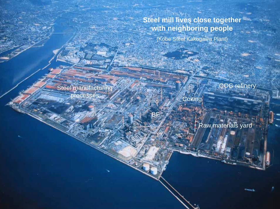
Raw materials yard
Coking
BF
COG refinerySteel manufacturing processes
Steel mill lives close together with neighboring people
(Kobe Steel Kakogawa Plant)
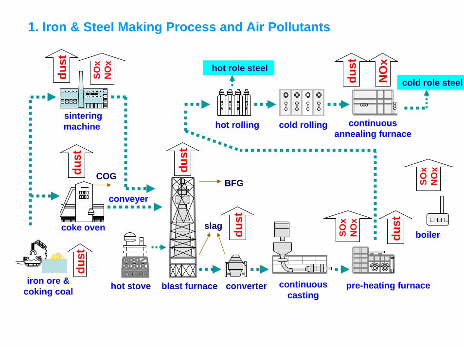
1. Iron & Steel Making Process and Air Pollutants
iron ore &coking coal
sinteringmachine
coke oven
hot stove blast furnace continuouscasting
converter pre-heating furnace
hot rolling cold rolling continuousannealing furnace
hot role steelcold role steel
COG BFG
slagboiler
conveyer
dust
SOx
NO
x
dust
SOx
NO
x
SOx
NO
x
NO
x
dust
dust
dust
dust
dust
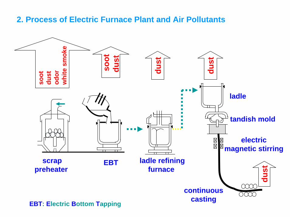
2. Process of Electric Furnace Plant and Air Pollutants
scrappreheater
EBT ladle refiningfurnace
ladle
tandish mold
electricmagnetic stirring
continuous casting
soot
dust
dust
dust
soot
dust
odor
whi
te s
mok
e
dust
EBT: Electric Bottom Tapping
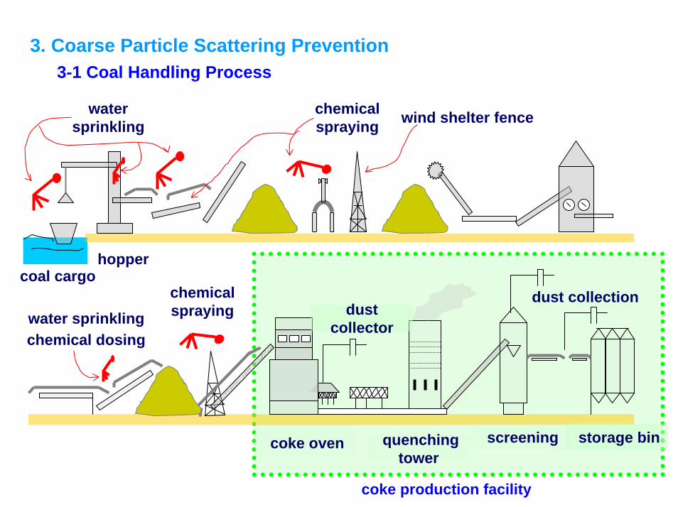
3. Coarse Particle Scattering Prevention3-1 Coal Handling Process
dust collectioncoal cargo
wind shelter fencewatersprinkling
chemical spraying
hopper
chemical dosingwater sprinkling
chemicalspraying
coke oven screeningquenchingtower
storage bin
dust collector
coke production facility
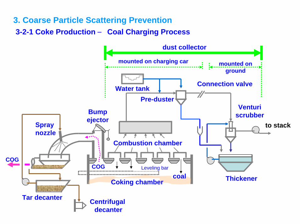
3. Coarse Particle Scattering Prevention3-2-1 Coke Production ― Coal Charging Process
mounted on ground
Centrifugaldecanter
Tar decanter
Coking chamber
Leveling bar
Combustion chamber
Water tankPre-duster
Connection valve
Venturiscrubber
to stack
Thickener
Spraynozzle
coalCOG
dust collector
mounted on charging car
Bumpejector
COG
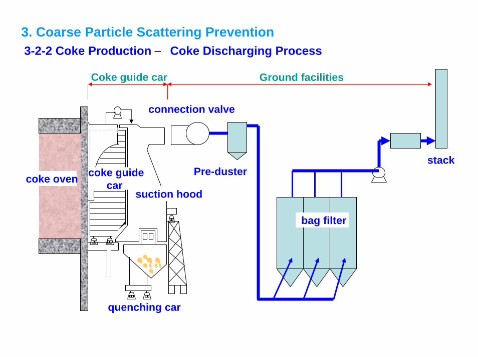
3. Coarse Particle Scattering Prevention3-2-2 Coke Production ― Coke Discharging Process
connection valve
coke guidecar
bag filter
Pre-dusterstack
quenching car
suction hoodcoke oven
Coke guide car Ground facilities
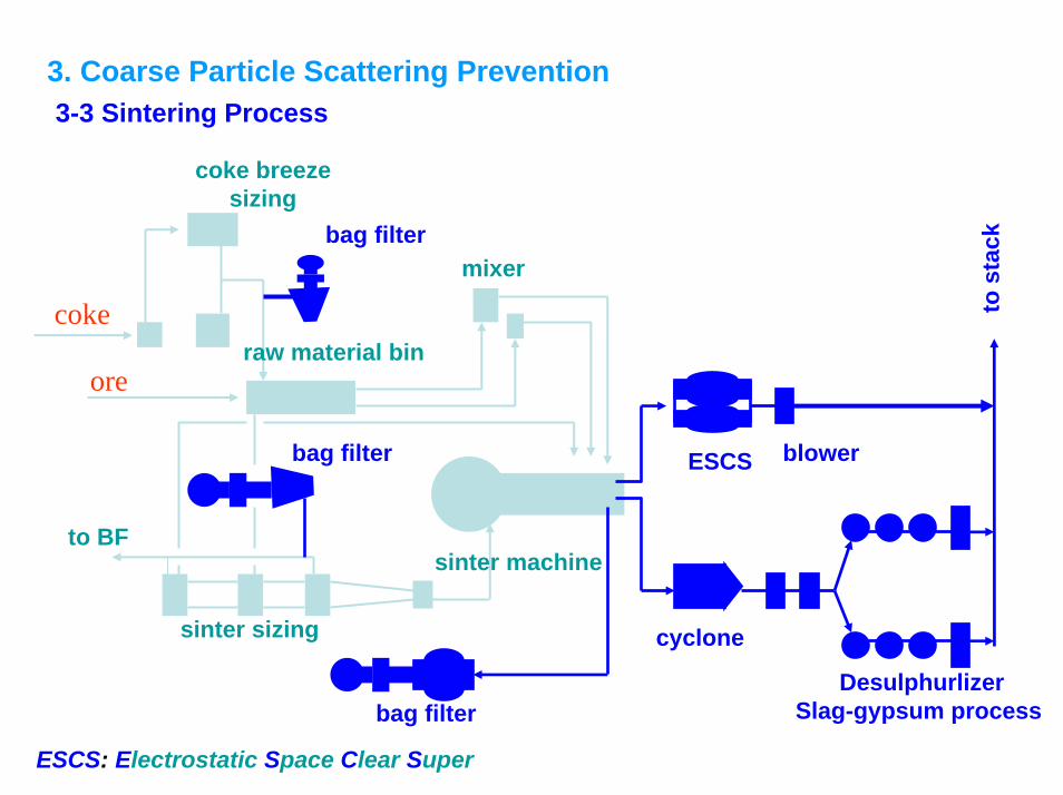
3. Coarse Particle Scattering Prevention3-3 Sintering Process
coke breeze sizing
to BF
sinter sizing
mixer
raw material bin
bag filter
ESCSbag filter
sinter machine
cyclone
blower
to s
tack
DesulphurlizerSlag-gypsum process
ESCS: Electrostatic Space Clear Super
bag filter
coke
ore
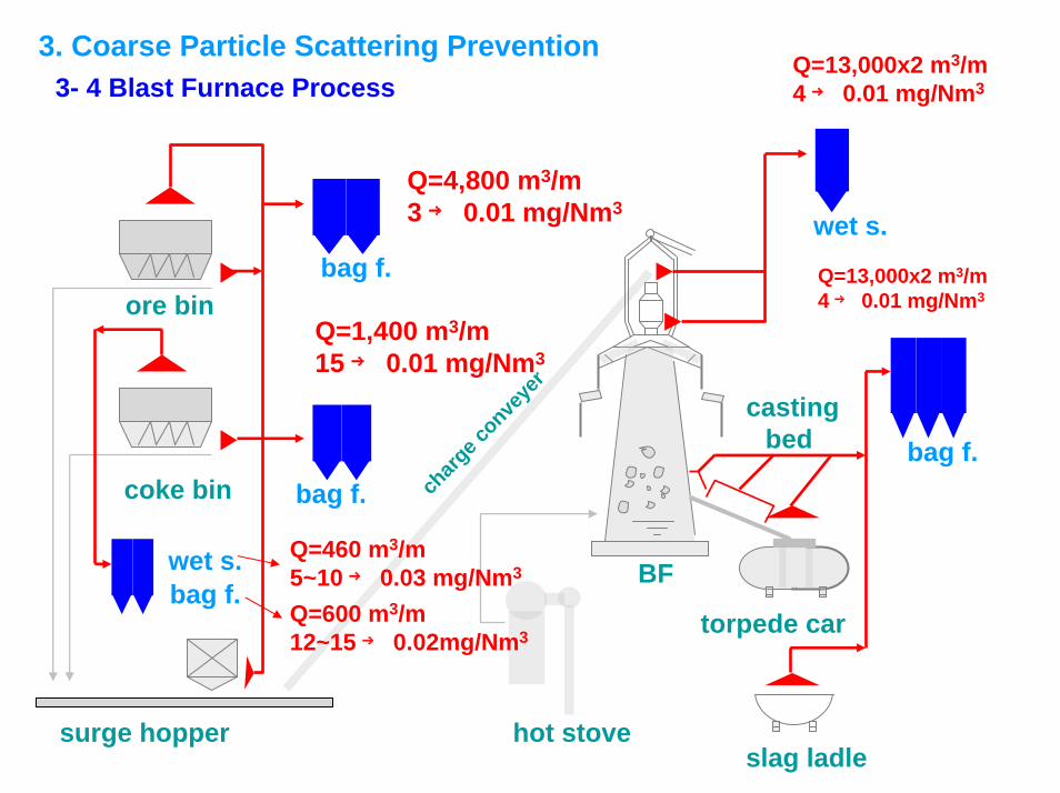
3. Coarse Particle Scattering Prevention3- 4 Blast Furnace Process
coke bin
ore bin
BF
surge hopper hot stove
torpede car
slag ladle
charg
e conve
yer
Q=13,000x2 m3/m4 → 0.01 mg/Nm3
Q=4,800 m3/m3 → 0.01 mg/Nm3
Q=13,000x2 m3/m4 → 0.01 mg/Nm3
Q=1,400 m3/m15 → 0.01 mg/Nm3
bag f.bag f.
bag f.
wet s.
wet s.
bag f.
Q=460 m3/m5~10 → 0.03 mg/Nm3
castingbed
Q=600 m3/m12~15 → 0.02mg/Nm3
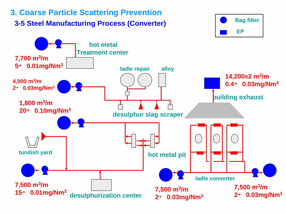
3. Coarse Particle Scattering Prevention3-5 Steel Manufacturing Process (Converter) Bag filter
EP
hot metalTreatment center
alloyladle repair
desulphur slag scraper
hot metal pit
desulphurization center
tundish yard
building exhaust
7,500 m3/m2→ 0.03mg/Nm3
1,800 m3/m20→ 0.10mg/Nm3
7,500 m3/m2→ 0.03mg/Nm3
7,500 m3/m15→ 0.01mg/Nm3
4,000 m3/m2→ 0.03mg/Nm3
7,700 m3/m5→ 0.01mg/Nm3
14,200x2 m3/m0.4→ 0.03mg/Nm3
ladle converter
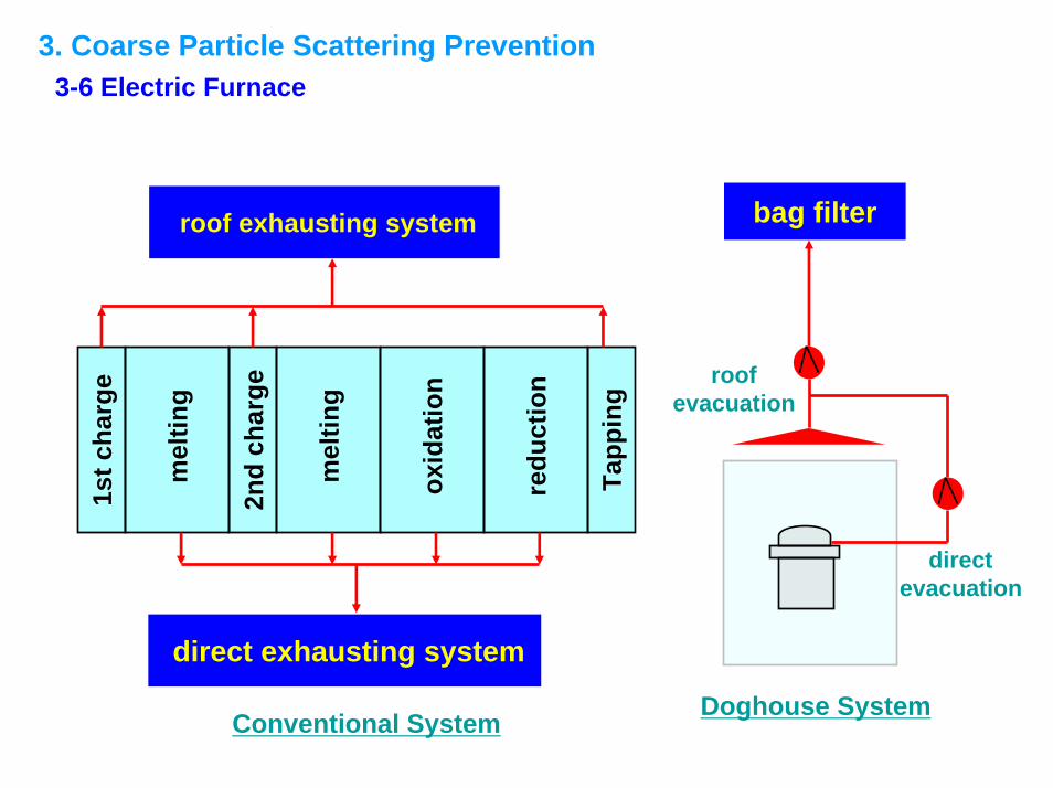
3. Coarse Particle Scattering Prevention3-6 Electric Furnace
bag filter
direct evacuation
Doghouse System
roof evacuation
1st c
harg
e
2nd
char
ge
Tapp
ing
mel
ting
mel
ting
oxid
atio
n
redu
ctio
n
roof exhausting system
direct exhausting system
Conventional System
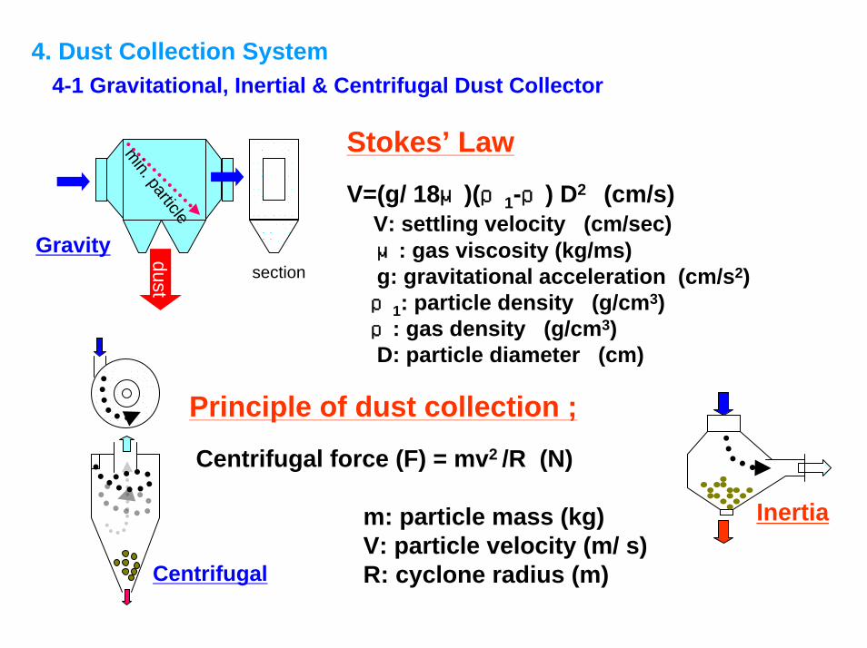
4-1 Gravitational, Inertial & Centrifugal Dust Collector4. Dust Collection System
min. particledust
section
Stokes’ Law
V=(g/ 18μ)(ρ1-ρ) D2 (cm/s)V: settling velocity (cm/sec)μ: gas viscosity (kg/ms)g: gravitational acceleration (cm/s2)ρ1: particle density (g/cm3)ρ: gas density (g/cm3)D: particle diameter (cm)
Principle of dust collection ;
Centrifugal force (F) = mv2 /R (N)
m: particle mass (kg)V: particle velocity (m/ s)R: cyclone radius (m)
Gravity
Inertia
Centrifugal
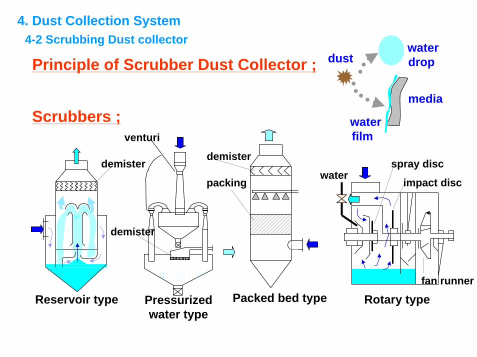
4. Dust Collection System4-2 Scrubbing Dust collector
Pressurizedwater type
Reservoir type Packed bed type
demister
demisterdemister
packing
Principle of Scrubber Dust Collector ;
venturi
dustwaterdrop
media
waterfilm
Scrubbers ;
Rotary type
waterspray disc
impact disc
fan runner
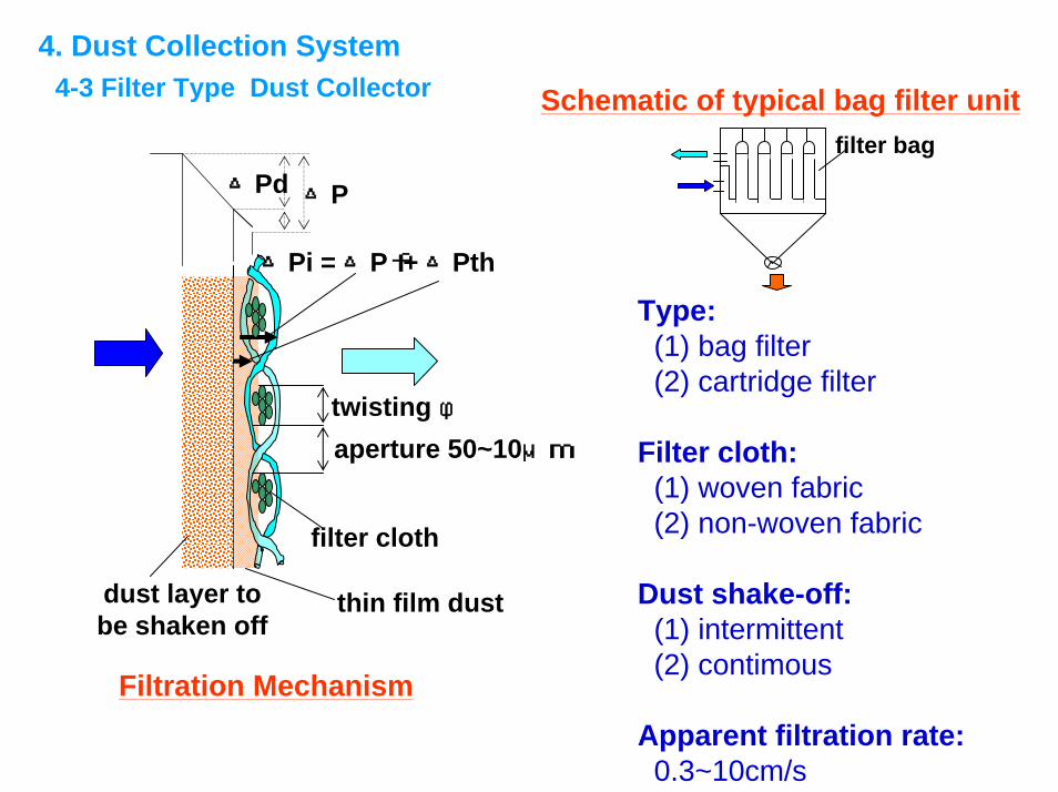
4. Dust Collection System4-3 Filter Type Dust Collector Schematic of typical bag filter unit
filter bag
filter cloth
dust layer tobe shaken off
thin film dust
△Pi = △Pf + △Pth
△P△Pd
twisting φaperture 50~10μm
Type: (1) bag filter(2) cartridge filter
Filter cloth:(1) woven fabric(2) non-woven fabric
Dust shake-off:(1) intermittent(2) contimous
Apparent filtration rate: Filtration Mechanism
0.3~10cm/s
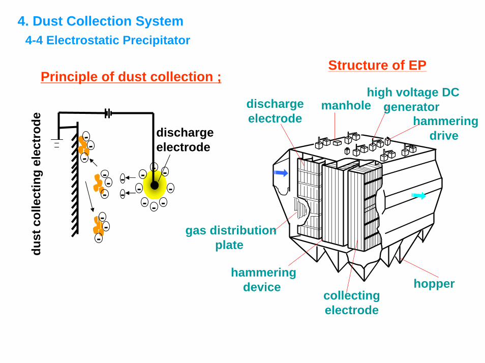
4. Dust Collection System4-4 Electrostatic Precipitator
-
- - --
----
--
--
-
discharge electrode
dust
col
lect
ing
elec
trod
e
--
--
-
Principle of dust collection ;
dischargeelectrode
gas distributionplate
manhole
collectingelectrode
hopperhammering
device
high voltage DCgenerator
hammeringdrive
Structure of EP
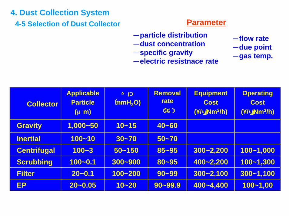
4. Dust Collection System4-5 Selection of Dust Collector Parameter
-particle distribution-dust concentration-specific gravity-electric resistnace rate
-flow rate-due point-gas temp.
CollectorApplicable
Particle (μm)
△p
〔mmH2O)Removal
rate(%)
Equipment Cost
(¥/y/Nm3/h)
OperatingCost
(¥/y/Nm3/h)
Gravity 1,000~50 10~15 40~60
Inertial 100~10 30~70 50~70Centrifugal 100~3 50~150 85~95 300~2,200 100~1,000Scrubbing 100~0.1 300~900 80~95 400~2,200 100~1,300Filter 20~0.1 100~200 90~99 300~2,100 300~1,100EP 20~0.05 10~20 90~99.9 400~4,400 100~1,00
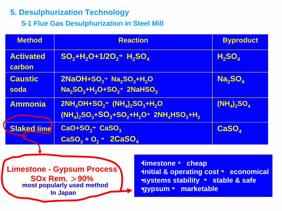
5. Desulphurization Technology5-1 Flue Gas Desulphurization in Steel Mill
Method Reaction Byproduct
Activatedcarbon
SO2+H2O+1/2O2→H2SO4 H2SO4
Causticsoda
2NaOH+SO2→Na2SO3+H2ONa2SO3+H2O+SO2→2NaHSO3
Na2SO4
Ammonia 2NH4OH+SO2→(NH4)2SO3+H2O(NH4)2SO3+SO3+SO2+H2O→2NH4HSO3+H2
(NH4)2SO4
Slaked lime CaO+SO2→CaSO3
CaSO3 + O2→ 2CaSO4
CaSO4
most popularly used methodIn Japan
Limestone - Gypsum ProcessSOx Rem. >90%
・limestone ⇒ cheap・initial & operating cost ⇒ economical・systems stability ⇒ stable & safe ・gypsum ⇒ marketable
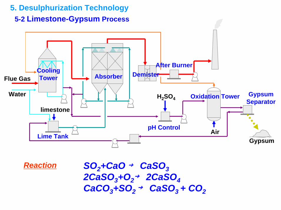
5. Desulphurization Technology5-2 Limestone-Gypsum Process
Gypsum
Flue Gas
Water
CoolingTower Absorber Demister
After Burner
Lime TankpH Control
Oxidation Tower GypsumSeparator
limestone
H2SO4
Reaction
Air
SO2+CaO → CaSO32CaSO3+O2→ 2CaSO4CaCO3+SO2 → CaSO3 + CO2
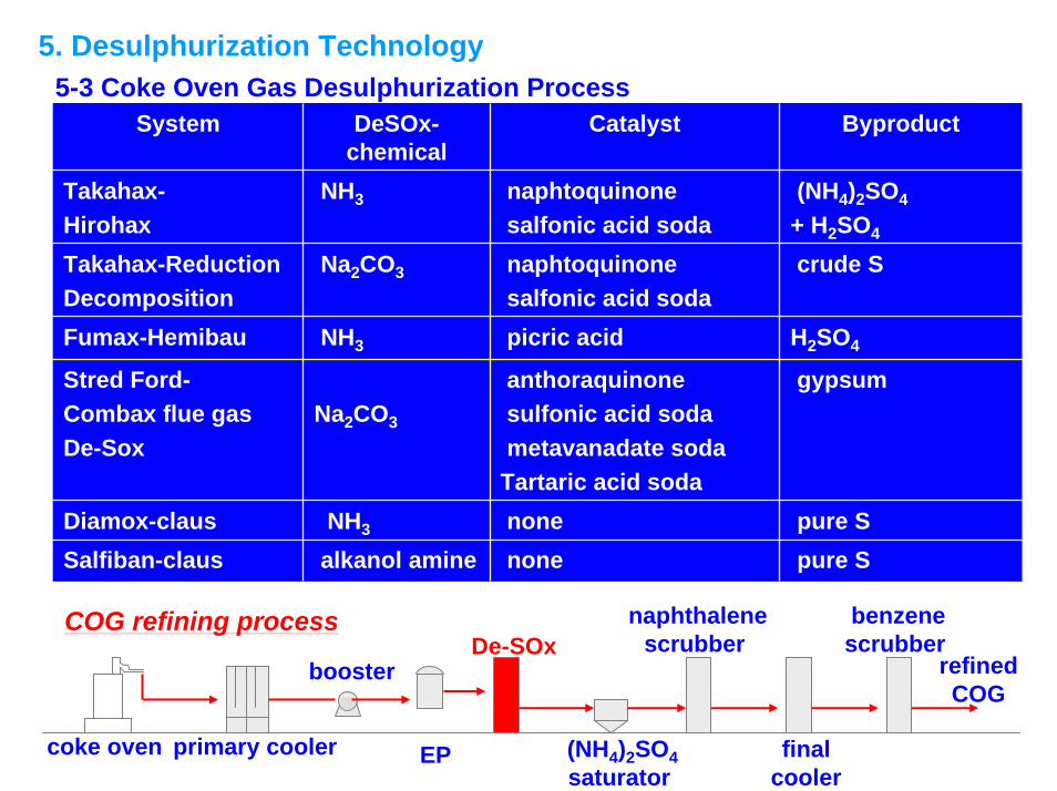
5. Desulphurization Technology5-3 Coke Oven Gas Desulphurization Process
System DeSOx-chemical
Catalyst Byproduct
Takahax-Hirohax
NH3 naphtoquinonesalfonic acid soda
(NH4)2SO4
+ H2SO4
Takahax-ReductionDecomposition
Na2CO3 naphtoquinonesalfonic acid soda
crude S
Fumax-Hemibau NH3 picric acid H2SO4
Stred Ford-Combax flue gasDe-Sox
Na2CO3
anthoraquinonesulfonic acid sodametavanadate soda
Tartaric acid soda
gypsum
Diamox-claus NH3 none pure SSalfiban-claus alkanol amine none pure S
refined COG
coke oven primary cooler EP
boosterDe-SOx
(NH4)2SO4saturator
naphthalenescrubber
finalcooler
benzenescrubber
COG refining process
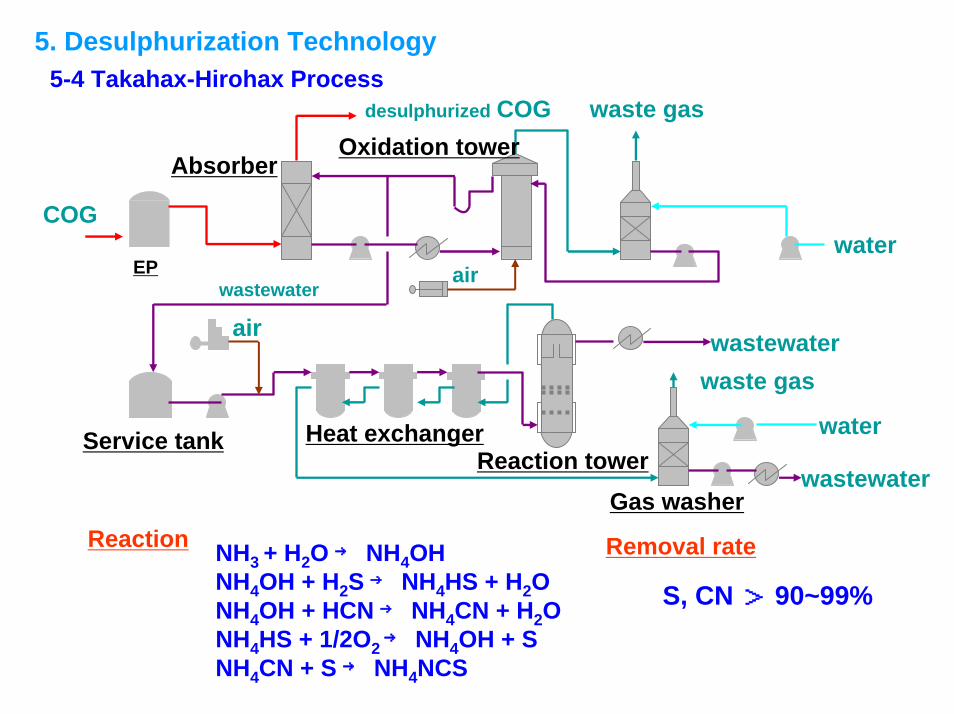
5. Desulphurization Technology5-4 Takahax-Hirohax Process
desulphurized COG
COG
waste gas
waste gas
water
air
airwater
wastewater
Absorber
EP
Oxidation tower
Service tank Heat exchangerReaction tower
wastewater
wastewater
Reaction NH3 + H2O → NH4OHNH4OH + H2S → NH4HS + H2ONH4OH + HCN → NH4CN + H2ONH4HS + 1/2O2 → NH4OH + SNH4CN + S → NH4NCS
Removal rate
S, CN > 90~99%
Gas washer
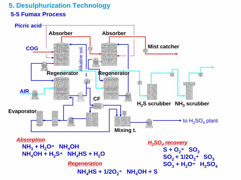
5. Desulphurization Technology5-5 Fumax Process
AbsorptionNH3 + H2O→ NH4OHNH4OH + H2S→ NH4HS + H2O
NH4HS + 1/2O2→ NH4OH + S
S + O2→ SO2SO2 + 1/2O2→ SO3SO3 + H2O→ H2SO4Regeneration
H2SO4 recovery
COG
Absorber
AIR
Absorber
Mist catcher
NH3 scrubberH2S scrubber
Alk
alin
e so
l.Regenerator
Evaporator
Picric acid
to H2SO4 plant
CF
Regenerator
Mixing t.
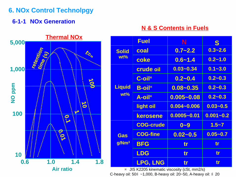
6. NOx Control Technolpgy6-1-1 NOx Generation
S Thermal NOxre
tent
ion
time
(s)
0.01
t=∞
10010
10.1
0.6 1.0 1.4 1.810
100
1,000
5,000
NO
ppm
Air ratio
N & S Contents in Fuels
0.3~2.60.7~2.2coal0.2~1.00.6~1.4coke0.1~3.00.03~0.34crude oil0.2~0.30.2~0.4C-oil※
0.2~0.30.08~0.35B-oil※
0.2~0.30.005~0.08A-oil※
0.03~0.50.004~0.006light oil
0.001~0.20.0005~0.01kerosene1.5~70~9COG-crude
0.05~0.70.02~0.5COG-fine
trtrBFGtrtrLDGtrtrLPG, LNG
NFuel
wt%Solid
Liquidwt%
Gasg/Nm3
S
※ JIS K2205 kinematic viscosity (cSt, mm2/s) C-heavy oil: 50≦~1,000, B-heavy oil: 20~50, A-heavy oil: ≦20
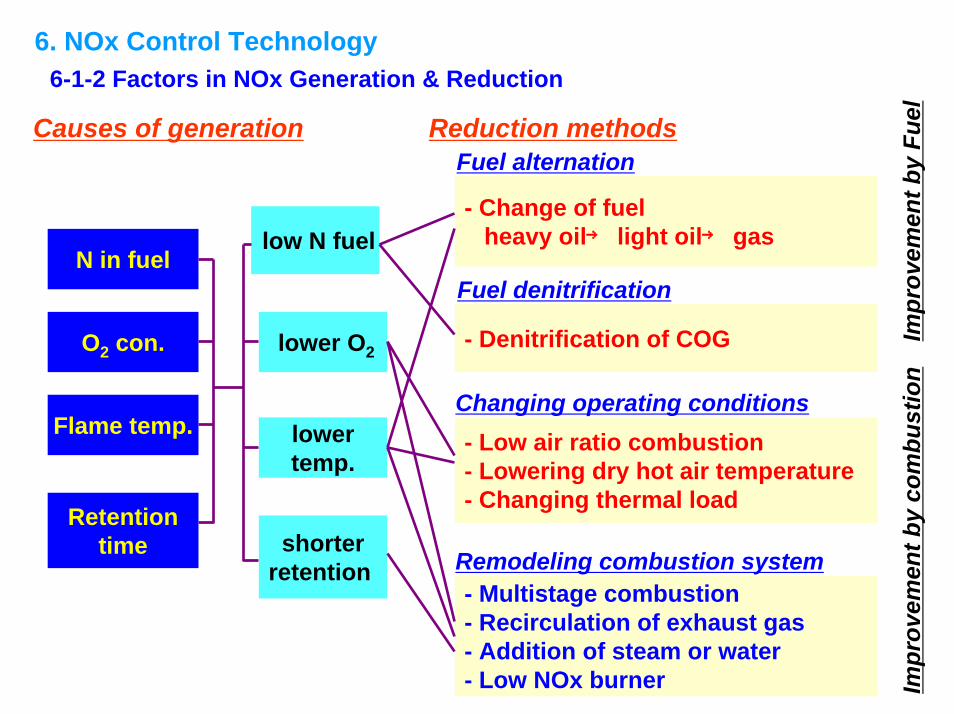
6. NOx Control Technology6-1-2 Factors in NOx Generation & Reduction
Impr
ovem
ent b
y Fu
elIm
prov
emen
t by
com
bust
ion
Fuel alternation
- Multistage combustion- Recirculation of exhaust gas- Addition of steam or water- Low NOx burner
- Change of fuelheavy oil→ light oil→ gas
- Denitrification of COG
- Low air ratio combustion- Lowering dry hot air temperature- Changing thermal load
Fuel denitrification
Changing operating conditions
Remodeling combustion system
Causes of generation Reduction methods
N in fuel
O2 con.
Flame temp.
Retentiontime
low N fuel
lower O2
lower temp.
shorter retention
6. NOx Control Technology6-2-1 Fuel Improvement
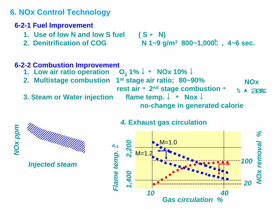
1. Use of low N and low S fuel ( S ∝ N)2. Denitrification of COG N 1~9 g/m3 800~1,000℃, 4~6 sec.
6-2-2 Combustion Improvement1. Low air ratio operation O2 1% ↓⇒ NOx 10% ↓2. Multistage combustion 1st stage air ratio; 80~90%
rest air →2nd stage combustion →3. Steam or Water injection flame temp. ↓⇒ Nox↓
no-change in generated calorie
4. Exhaust gas circulation
NO
xre
mov
al %
Gas circulation %
100
20
Flam
e te
mp.
℃
10 40
1,40
02,
200 M=1.0
M=1.2
Injected steam
NO
xpp
m
NOx≒▲20%
6. NOx Control Technology ― Continued from previous slide ―
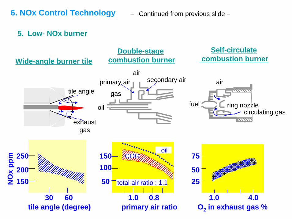
5. Low- NOx burner
Wide-angle burner tileDouble-stage
combustion burnerSelf-circulate
combustion burner
air
oil
gas
primary air secondary air
tile angle
exhaustgas
fuel ring nozzle
air
circulating gas
tile angle (degree)
NO
xpp
m
30 60primary air ratio
0.81.0
150100
50 total air ratio : 1.1
oilCOG250
150200
1.0 4.0
50
75
25
O2 in exhaust gas %
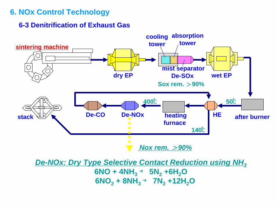
6. NOx Control Technology6-3 Denitrification of Exhaust Gas
dry EP
sintering machinecoolingtower
absorptiontower
mist separatorDe-SOx wet EP
after burnerHEheating furnace
De-NOxDe-COstack
Sox rem. >90%
Nox rem. >90%
50℃400℃
140℃
De-NOx: Dry Type Selective Contact Reduction using NH36NO + 4NH3→ 5N2 +6H2O6NO2 + 8NH3→ 7N2 +12H2O
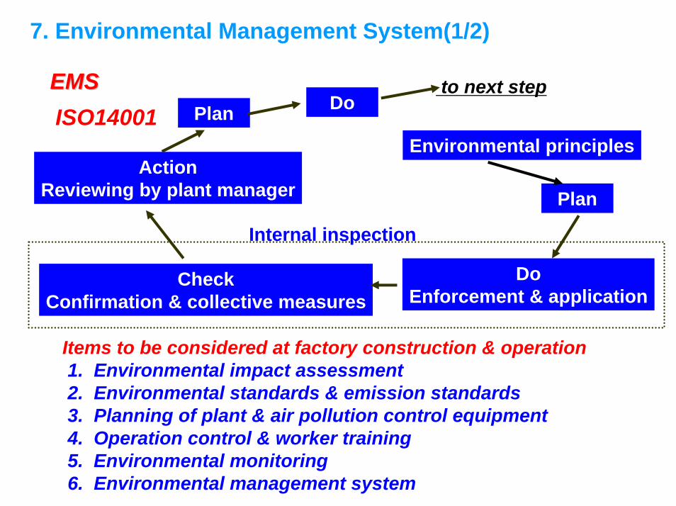
7. Environmental Management System(1/2)
Items to be considered at factory construction & operation1. Environmental impact assessment2. Environmental standards & emission standards3. Planning of plant & air pollution control equipment4. Operation control & worker training5. Environmental monitoring6. Environmental management system
Plan
DoEnforcement & application
CheckConfirmation & collective measures
Plan
Do
Environmental principlesAction
Reviewing by plant manager
EMSEMS
Internal inspection
to next stepISO14001
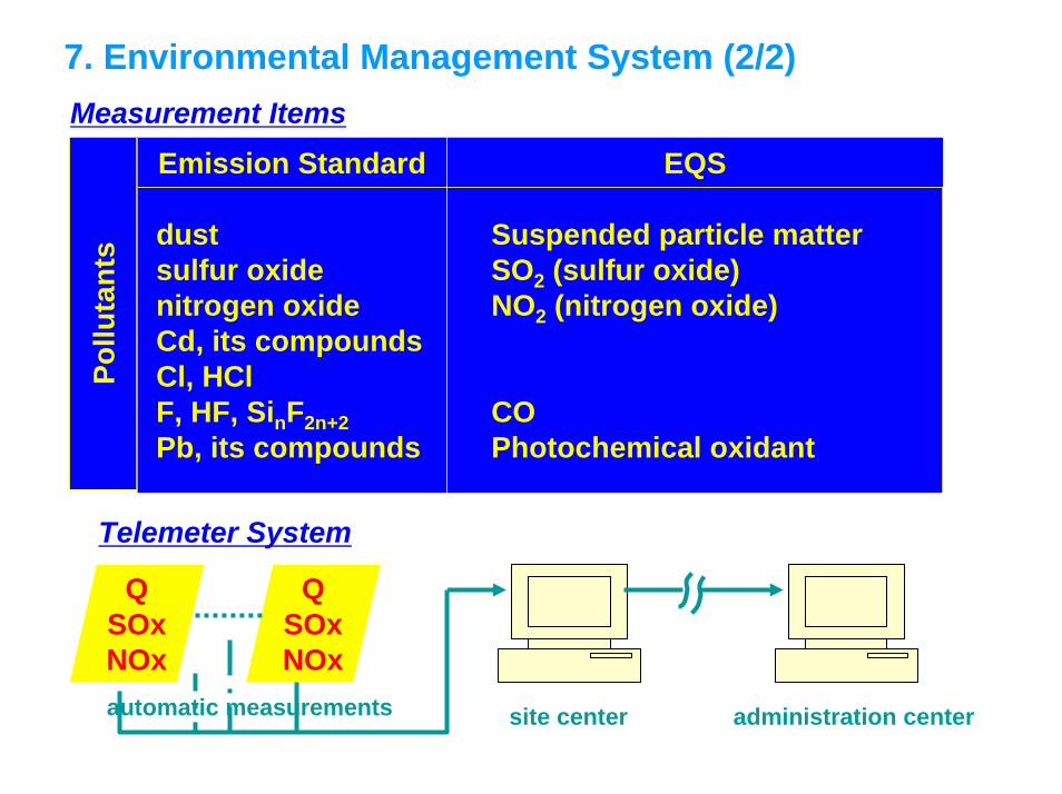
7. Environmental Management System (2/2)Measurement Items
Pollu
tant
s
Emission Standard
dustsulfur oxidenitrogen oxideCd, its compoundsCl, HClF, HF, SinF2n+2Pb, its compounds
Suspended particle matterSO2 (sulfur oxide)NO2 (nitrogen oxide)
COPhotochemical oxidant
EQS
Telemeter System
QSOxNOx
QSOxNOx
automatic measurements site center administration center
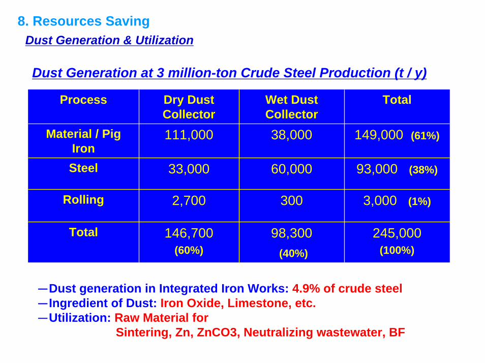
8. Resources SavingDust Generation & Utilization
-Dust generation in Integrated Iron Works: 4.9% of crude steel-Ingredient of Dust: Iron Oxide, Limestone, etc.-Utilization: Raw Material for
Sintering, Zn, ZnCO3, Neutralizing wastewater, BF
Process Dry Dust Collector
Wet Dust Collector
Total
Material / Pig Iron
111,000 38,000 149,000 (61%)
Steel 33,000 60,000 93,000 (38%)
Rolling 2,700 300 3,000 (1%)
Total 146,700 (60%)
98,300(40%)
245,000 (100%)
Dust Generation at 3 million-ton Crude Steel Production (t / y)
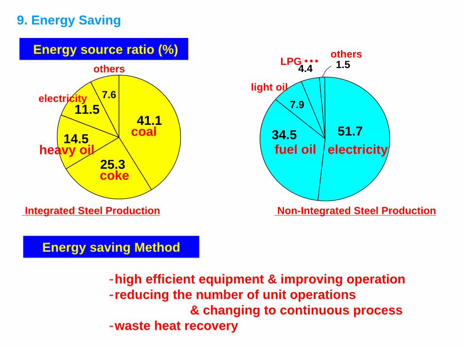
9. Energy Saving
Energy source ratio (%)
electricity
41.1
7.6
25.3
14.5
11.5coal
coke
others
heavy oil
Integrated Steel Production
7.9
51.734.5
4.4 1.5
electricityfuel oil
LPG・・・
light oil
others
Non-Integrated Steel Production
Energy saving Method
‐high efficient equipment & improving operation‐reducing the number of unit operations
& changing to continuous process‐waste heat recovery