Embed Size (px)
Citation preview
Section 1 LFLS
1 - 76
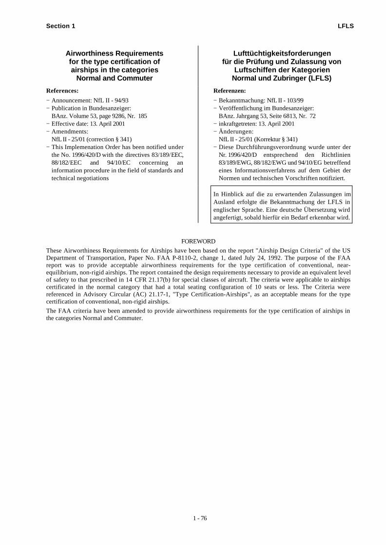
Airworthiness Requirementsfor the type certification ofairships in the categories
Normal and Commuter
Lufttüchtigkeitsforderungenfür die Prüfung und Zulassung von
Luftschiffen der KategorienNormal und Zubringer (LFLS)
References:
− Announcement: NfL II - 94/93− Publication in Bundesanzeiger:
BAnz. Volume 53, page 9286, Nr. 185− Effective date: 13. April 2001− Amendments:
NfL II - 25/01 (correction § 341)− This Implemenation Order has been notified under
the No. 1996/420/D with the directives 83/189/EEC,88/182/EEC and 94/10/EC concerning aninformation procedure in the field of standards andtechnical negotiations
Referenzen:
− Bekanntmachung: NfL II - 103/99− Veröffentlichung im Bundesanzeiger:
BAnz. Jahrgang 53, Seite 6813, Nr. 72− inkraftgetreten: 13. April 2001− Änderungen:
NfL II - 25/01 (Korrektur § 341)− Diese Durchführungsverordnung wurde unter der
Nr. 1996/420/D entsprechend den Richtlinien83/189/EWG, 88/182/EWG und 94/10/EG betreffendeines Informationsverfahrens auf dem Gebiet derNormen und technischen Vorschriften notifiziert.
In Hinblick auf die zu erwartenden Zulassungen imAusland erfolgte die Bekanntmachung der LFLS inenglischer Sprache. Eine deutsche Übersetzung wirdangefertigt, sobald hierfür ein Bedarf erkennbar wird.
FOREWORD
These Airworthiness Requirements for Airships have been based on the report "Airship Design Criteria" of the USDepartment of Transportation, Paper No. FAA P-8110-2, change 1, dated July 24, 1992. The purpose of the FAAreport was to provide acceptable airworthiness requirements for the type certification of conventional, near-equilibrium, non-rigid airships. The report contained the design requirements necessary to provide an equivalent levelof safety to that prescribed in 14 CFR 21.17(b) for special classes of aircraft. The criteria were applicable to airshipscertificated in the normal category that had a total seating configuration of 10 seats or less. The Criteria werereferenced in Advisory Circular (AC) 21.17-1, "Type Certification-Airships", as an acceptable means for the typecertification of conventional, non-rigid airships.
The FAA criteria have been amended to provide airworthiness requirements for the type certification of airships inthe categories Normal and Commuter.
Section 1 LFLS
2 - 76
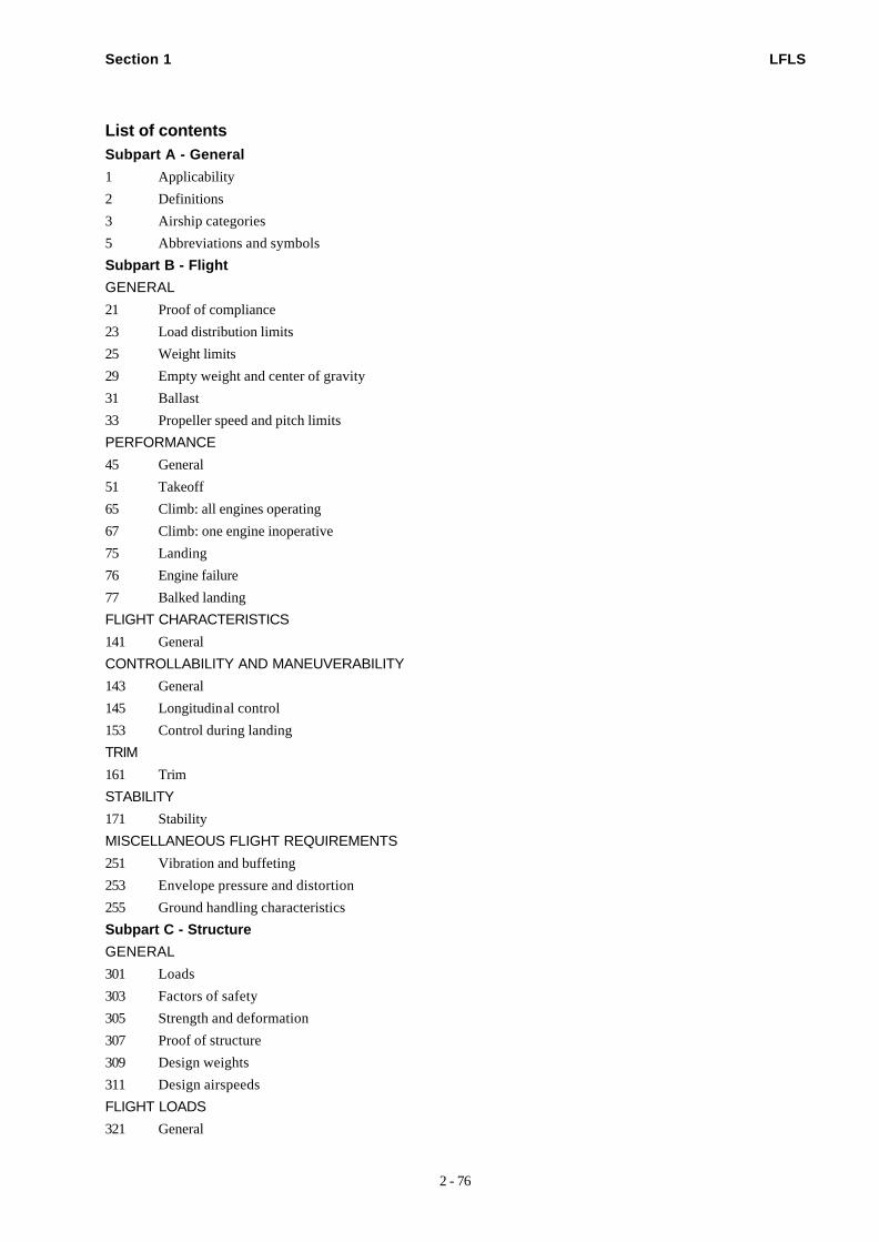
List of contentsSubpart A - General1 Applicability
2 Definitions
3 Airship categories
5 Abbreviations and symbols
Subpart B - FlightGENERAL21 Proof of compliance
23 Load distribution limits
25 Weight limits
29 Empty weight and center of gravity
31 Ballast
33 Propeller speed and pitch limits
PERFORMANCE45 General
51 Takeoff
65 Climb: all engines operating
67 Climb: one engine inoperative
75 Landing
76 Engine failure
77 Balked landing
FLIGHT CHARACTERISTICS141 General
CONTROLLABILITY AND MANEUVERABILITY143 General
145 Longitudinal control
153 Control during landing
TRIM161 Trim
STABILITY171 Stability
MISCELLANEOUS FLIGHT REQUIREMENTS251 Vibration and buffeting
253 Envelope pressure and distortion
255 Ground handling characteristics
Subpart C - StructureGENERAL301 Loads
303 Factors of safety
305 Strength and deformation
307 Proof of structure
309 Design weights
311 Design airspeeds
FLIGHT LOADS321 General
Section 1 LFLS
3 - 76
333 Design maneuver loads
341 Gust loads
361 Engine torque
363 Side load on engine mount
367 Engine failure loads
371 Gyroscopic loads
CONTROL SURFACE AND SYSTEM LOADS391 Control surface loads
395 Control system loads
397 Pilot forces
399 Dual control system
405 Secondary control system
407 Trim tabs effects
409 Tabs
411 Supplementary conditions for control surfaces
415 Tail-to-wind loads
GROUND LOADS471 General
473 Ground load conditions and assumptions
479 Landing conditions
481 Mooring and handling conditions
OTHER LOADS505 Snow loads
507 Jacking loads
509 Step section
EMERGENCY LANDING CONDITIONS561 General
FATIGUE EVALUATION572 Airship structures
573 Damage tolerance and fatigue evaluation of structure
Subpart D - Design and Construction601 General
603 Materials and workmanship
605 Fabrication methods
607 Fastenings
609 Protection of structure
611 Accessibility
613 Material strength properties and design values
619 Special factors
621 Casting factors
623 Bearing factors
625 Fitting factors
627 Fatigue strength
CONTROL SURFACES651 Proof of strength
655 Installation
Section 1 LFLS
4 - 76
657 Hinges
659 Mass balance
CONTROL SYSTEMS671 General
673 Primary flight controls
675 Stops
677 Trim systems
679 Control system locks
681 Limit load static tests
683 Operation tests
685 Control system details
687 Spring devices
689 Cable Systems
693 Joints
LANDING GEAR721 General
723 Shock absorption test
729 Landing gear extension and retraction system
731 Wheels
733 Tires
PERSONNEL AND CARGO ACCOMMODATIONS771 Pilot compartment
773 Pilot compartment view
775 Windshields and windows
777 Cockpit controls
779 Motion and effect of cockpit controls
783 Doors
785 Seats, berths, and safety belts
787 Baggage and cargo compartments
803 Emergency evacuation demonstration
807 Emergency exits
811 Emergency exit marking
813 Emergency exit access
815 Width of aisle
831 Ventilation
FIRE PROTECTION AND LIGHTNING EVALUATION851 Fire extinguishers
853 Compartment interiors
863 Flammable fluid fire protection
865 Fire protection of flight controls and other flight structure
867 Electrical bonding and lightning discharge protection
ENVELOPE881 Envelope design
883 Pressure system
885 Ground handling
887 Flutter
Section 1 LFLS
5 - 76
MISCELLANEOUS891 Lifting gas
893 Ballast system
895 Leveling means
Subpart E - PowerplantGENERAL
901 Installation
903 Engines
905 Propellers
907 Propeller vibration
909 Turbosuperchargers
925 Propeller clearance
929 Engine installation ice protection
933 Reversing systems
937 Turbopropeller -- drag limiting systems
939 Powerplant operating characteristics
943 Negative acceleration
FUEL SYSTEM951 General
953 Fuel system independence
954 Fuel system lightning protection
955 Fuel flow
957 Flow between interconnected tanks
959 Unusable fuel supply
961 Fuel system hot weather operation
963 Fuel tanks: general
965 Fuel tank tests
967 Fuel tank installation
969 Fuel tank expansion space
971 Fuel tank sump
973 Fuel tank filler connection
975 Fuel tank vents and carburetor vapor vents
977 Fuel tank outlet
979 Pressure fuelling system
FUEL SYSTEM COMPONENTS991 Fuel pumps
993 Fuel system lines and fittings
994 Fuel system components
995 Fuel values and controls
997 Fuel strainer or filter
999 Fuel system drains
1001 Fuel jettisoning system
OIL SYSTEM1011 General
1013 Oil tanks
1015 Oil tank tests
Section 1 LFLS
6 - 76
1017 Oil lines and fittings
1019 Oil strainer or filter
1021 Oil system drains
1023 Oil radiators
1027 Propeller feathering system
COOLING1041 General
1043 Cooling tests
1046 Cooling test procedures
LIQUID COOLING(Reserved)
INDUCTION SYSTEM1091 Air induction
1093 Induction system icing protection
1101 Carburetor air preheater design
1103 Induction system ducts
1105 Induction system screens
1111 Turbine engine bleed-air system
EXHAUST SYSTEM1121 General
1123 Exhaust manifold
1125 Exhaust heat exchangers
POWERPLANT CONTROLS AND ACCESSORIES1141 Powerplant controls: general
1143 Engine controls
1145 Ignition switches
1147 Mixture controls
1149 Propeller speed and pitch controls
1153 Propeller feathering controls
1157 Carburetor air temperature controls
1163 Powerplant accessories
1165 Engine ignition systems
1167 Vectored thrust controls
1169 Auxiliary power unit controls
POWERPLANT FIRE PROTECTION1182 Nacelle areas adjacent to engine firewalls
1183 Lines, fittings, and components
1188 Ventilation
1189 Shutoff means
1191 Firewalls
1192 Engine accessory compartment diaphragm
1193 Engine cowling
1195 Fire extinguishing systems
1197 Fire extinguishing agents
1199 Extinguishing agent containers
1201 Fire extinguishing system materials
Section 1 LFLS
7 - 76
1203 Fire detector system
1205 Vectored thrust
Subpart F - EquipmentGENERAL1301 Function and installation
1303 Flight and navigation instruments
1305 Powerplant instruments
1306 Miscellaneous equipment instruments
1307 Miscellaneous equipment
1309 Equipment, systems, and installations
1311 Protection from the effects of HIRF (Reserved)
1316 System lightning protection
INSTRUMENTS: INSTALLATION1321 Arrangement and visibility
1322 Warning, caution, and advisory lights
1323 Airspeed indicating system
1325 Static pressure system
1327 Magnetic direction indicator
1329 Automatic pilot system
1330 Electronic flight instrument systems (EFIS)
1331 Instruments using a power supply
1335 Flight director systems
1337 Powerplant instruments
ELECTRICAL SYSTEMS AND EQUIPMENT1351 General
1353 Storage battery design and installation
1357 Circuit protective devices
1361 Master switch arrangement
1365 Electric cables and equipment
1367 Switches
LIGHTS1381 Instrument lights
1383 Landing lights
1385 Position light system installation
1387 Position light system dihedral angles
1389 Position light distribution and intensities
1391 Minimum intensities in the horizontal plane of bow, forward, and rear position lights
1393 Minimum intensities in any vertical plane of bow, forward and rear position lights
1395 Maximum intensities in overlapping beams of forward and rear position lights
1397 Color specifications
1401 Anticollision light system
SAFETY EQUIPMENT1411 General
1413 Safety belts
1414 Electrostatic discharge equipment
1415 Ditching equipment
Section 1 LFLS
8 - 76
1419 Ice protection equipment
MISCELLANEOUS EQUIPMENT1431 Electronic equipment
1435 Hydraulic systems
1437 Accessories for multiengine airships
1438 Pressurization and pneumatic systems
1461 Equipment containing high energy rotors
Subpart G - Operating Limitations and Information1501 General
OPERATING LIMITATIONS1505 Airspeed limitations
1519 Weight and center of gravity
1521 Powerplant limitations
1522 Auxiliary power unit limitations
1523 Minimum flight crew
1524 Maximum passenger-seating configuration
1525 Kinds of operation
1526 Maximum rates of ascent and descent
1527 Engine vectoring
1528 Envelope and ballonet pressures
1529 Instructions for continued airworthiness
MARKINGS AND PLACARDS1541 General
1543 Instrument markings: general
1545 Airspeed indicator
1547 Magnetic direction indicator
1549 Powerplant and auxiliary power unit instruments
1551 Oil quantity indicator
1553 Fuel quantity indicator
1555 Control markings
1557 Miscellaneous markings and placards
1559 Operating limitations placard
1561 Safety equipment
1563 Airspeed placard
AIRSHIP FLIGHT MANUAL1581 General
1583 Operating limitations
1585 Operating procedures
1587 Performance information
1589 Loading information
Section 1 LFLS
9 - 76
Subpart A - General§ 1 Applicability
(a) These regulations prescribe acceptable airworthiness requirements, applicable to near-equilibrium, conventionalairships in the normal and commuter categories, consisting of an envelope filled with the lifting gas and pressurizedslightly above ambient, for the issuance of type certificates and changes to those certificates.
(b) Each person who applies for such a certificate or change must show compliance with the applicable require-ments in these regulations.
(c) Additional requirements may be required to cover airship design features or operational characteristics not en-visioned in this document.
§ 2 DefinitionsThe following apply.
(a) An airship is an engine-driven, lighter-than-air aircraft, that can be steered.
(b) A pressure envelope airship is one whose shape is maintained by the pressure of the lifting gas containedwithin the envelope.
(c) A near-equilibrium airship is one which is capable of achieving zero static heaviness during normal flight opera-tions.
(d) A car is a structure attached to or suspended from the envelope or the structure for carrying crew members,passengers, cargo, equipment, or propulsion systems.
(e) Pressure height is the altitude at which the lifting gas fills the envelope with the ballonets completely deflated.
(f) Weight of pure gases at standard sea level atmospheric condition of 29.92 in Hg pressure and 60 °F tempera-ture:
(1) Dry air 0.07647 lb/ft3,
(2) Dry helium 0.01054 lb/ft3.
(g) Unit lift - the value used should be identified in the analysis of the design. In the absence of a rational analysis,0.0635 lb/ft3 (96 percent purity) should be used for helium.
(h) Ballonet - a flexible and collapsible air cell contained within the envelope for the purpose of compensating forgas volume changes, maintaining internal pressure in the envelope, and assisting in trimming the airship.
(i) Virtual Inertia - the apparent additional inertia of a body moving in a fluid due to the motion on that fluid by thebody.
§ 3 Airship categories(a) The normal category is limited to airships that have a seating configuration, excluding pilot seats, of nine or
less.
(b) The commuter category is limited to propeller-driven, multiengine airships that have a seating configuration ex-cluding pilot seats, of 19 or less.
(c) Airships may be type certificated in more than one category of these regulations if the requirements of each re-quested category are met.
§ 5 Abbreviations and symbolsAbbreviations and symbols are in accordance to FAR Part 1. Speeds are equivalent airspeeds (EAS) unless indicatedotherwise.
Subpart B - FlightGENERAL
§ 21 Proof of compliance(a) Each requirement of these regulations must be met at the appropriate weight and center of gravity within the
range of loading conditions for which certification is requested. This must be shown by tests upon an airship of thetype for which certification is requested, or by calculations based on and equal in accuracy to the results of testing.
(b) The general tolerances of Table 5 of the appendix are allowed during flight testing; however, greater tolerancesmay be allowed in particular test.
§ 23 Load distribution limitsRanges of weight and centers of gravity within which the airship may be safely operated must be established.
Section 1 LFLS
10 - 76
§ 25 Weight limits(a) Maximum weight. The maximum weight is the highest weight at which compliance with each applicable require-
ment of these regulations is shown. The maximum weight must be established so that it is
(1) Not more than
(i) The highest weight selected by the applicant,
(ii) The design maximum weight, which is the highest weight at which compliance with each applicable structuralloading condition of these regulations is shown, or
(iii) The highest weight at which compliance with each applicable flight requirement is shown;
(2) Assuming a weight of 170 pounds for each occupant of each seat, not less than the weight with
(i) Each seat occupied, oil at full tank capacity, and at least enough fuel for one-half hour of operation at ratedmaximum continuous power, or
(ii) The required minimum crew, and fuel and oil at full tank capacity;
(3) Not less than that which can be achieved with the car loaded to its maximum design weight.
(b) Minimum weight. The design minimum weight must be established so that it is not more than the sum of
(1) The empty weight determined under section 29;
(2) The weight of the required minimum crew (assuming a weight of 170 pounds for each crew member); and
(3) The weight of the fuel necessary for one-half hour of operation at maximum continuous power.
§ 29 Empty weight and center of gravity(a) The empty weight and corresponding center of gravity must be determined from the weight of all items, includ-
ing the structure, if any, and
(1) The weight of the deflated envelope;
(2) Fixed ballast;
(3) Unusable fuel determined under section 959; and
(4) Full operating fluids, including
(i) Oil and
(ii) Hydraulic fluid.
(b) The condition of the airship at the time of determining empty weight must be one that is well defined and re-peatable.
§ 31 BallastRemovable ballast may be used in showing compliance with the flight requirements of this subpart, if
(a) The place for carrying ballast is properly designed and installed, and is marked under section 1557;
(b) Instructions are included in the Airship Flight Manual, approved manual material, or markings and placards, forthe proper placement of the removable ballast under each loading condition for which removable ballast is necessary.
§ 33 Propeller speed and pitch limits(a) General. The propeller speed and pitch must be limited to values that will assure safe operation under normal
operating conditions.
(b) Propellers not controllable in flight. For each propeller whose pitch cannot be controlled in flight, during takeoffand initial climb at best rate of climb speed, the propeller must limit the engine r.p.m., at full throttle or at maximumallowable takeoff manifold pressure, to a speed not greater than the maximum allowable takeoff r.p.m.
(c) Controllable pitch propellers without constant speed controls. Each propeller that can be controlled in flight,but that does not have constant speed controls, must have a means to limit the pitch range so that the lowest possiblepitch allows compliance with paragraph (b) of this section.
(d) Controllable pitch propellers with constant speed controls. Each controllable pitch propeller with constantspeed controls must have
(1) With the speed control in operation, a means at the speed control to limit the maximum engine speed to themaximum allowable takeoff r.p.m.;
(2) With the speed control inoperative, a means to limit the maximum engine speed to 1.03 of the maximum allow-able takeoff r.p.m. with the propeller blades at the lowest possible pitch and with takeoff manifold pressure, the airshipstationary, and no wind.
Section 1 LFLS
11 - 76
PERFORMANCE§ 45 General
(a) Unless otherwise prescribed, the performance requirements of this subpart must be met for still air; and
(1) Standard atmospheric conditions for normal category airships; or
(2) Ambient atmospheric conditions for commuter category airships.
(b) The performance data must correspond to the vectored, propulsive thrust available under the particular ambientatmospheric conditions, the particular flight condition, and the relative humidity specified in paragraph (d) of thissection.
(c) The available propulsive thrust must correspond to engine power or thrust, not exceeding the approved poweror thrust, less
(1) Installation losses;
(2) The power or equivalent thrust absorbed by the accessories and services appropriate to the particular amb i-ent atmospheric conditions and the particular flight condition.
(d) The performance, as affected by engine power or thrust, must be based on a relative humidity of
(1) 0.80 at or below standard temperature;
(2) 0.34 at and above standard temperature, plus 50 °F.
(3) Between the two temperatures listed in subparagraphs (d)(1) and (d)(2) of this section, the relative humiditymust vary linearly.
(e) For commuter category airships, the following also apply.
(1) Unless otherwise prescribed, the applicant must select the takeoff, en route, approach, and landing configura-tions for the airship;
(2) The airship configuration may vary with weight, altitude, and temperature, to the extent they are compatiblewith the operating procedures required by subparagraph (e)(3) of this section;
(3) Unless otherwise prescribed, in determining the critical-engine-inoperative takeoff performance, takeoff flightpath, the accelerate-stop distance, takeoff distance, and landing distance, changes in he airship's configuration, speed,power, and thrust must be made in accordance with procedures established by the applicant for operation in service;
(4) Procedures for the execution of missed approaches and balked landings associated with the conditions pre-scribed in sections 67 and 77 must be established;
(5) The procedures established under subparagraphs (e)(3) and (e)(4) of this section must
(i) Be able to be consistently executed by a crew of average skill,
(ii) Use methods or devices that are safe and reliable,
(iii) Include allowance for any reasonably expected time delays in the execution of the procedures.
§ 51 Takeoff(a) For each airship, the distance required to takeoff and climb over a 50-foot obstacle must be determined with
(1) The airship at maximum static heaviness;
(2) The engines operating within approved operating limitations;
(3) The cowl flaps or other means for controlling the engine cooling air supply in normal takeoff position;
(4) The engines, and/or propellers, vectored, if so equipped, to each position for which takeoff approval issought.
(b) (Reserved)
(c) Takeoffs made to determine the data required by this section may not require exceptional piloting skill or excep-tional favorable conditions.
(d) For commuter category airships, takeoff performance and data must be determined and included in the AirshipFlight Manual
(1) For each weight, altitude, and ambient temperature within the operational limits selected by the applicant;
(2) For the selected configuration for takeoff;
(3) For the most unfavorable center of gravity position;
(4) With the operating engine within approved operating limitations.
Section 1 LFLS
12 - 76
(e) Upon reaching a height of 50 feet above the takeoff surface, the airship must have reached the recommendedclimb speed; and
(f) Takeoffs made to determine the data required by this section may not require exceptional piloting skill or excep-tionally favorable conditions.
§ 65 Climb: all engines operating(a) Each airship must have a steady rate of climb at sea level of at least 300 feet per minute and a steady angle of
climb of at least 1:12 with
(1) Not more than maximum continuous power an each engine;
(2) Auxiliary thrust and lift controls in their normal position for climb;
(3) The landing gear retracted; and
(4) The cowl flaps or other means for controlling the engine cooling air supply in the position used in the coolingtests required by sections 1041 through 1046.
(b) The maximum rates of ascent and descent, to be used for all operations, must be established for all conditionsusing maximum continuous forward thrust. It must be demonstrated that envelope pressures remain within the maxi-mum and minimum approved pressures during climbs and descents at those maximum rates.
(c) (Reserved)
(d) In addition for commuter category airships, performance data must be determined for variations in weight, alti-tude, and temperature at the most critical center of gravity for which approval is requested.
§ 67 Climb: One engine inoperativeEach multiengined airship must have a steady rate of climb at sea level of at least 100 feet per minute with
(a) One engine inoperative and its propeller in the minimum drag position;
(b) Remaining engines at not more than maximum continuous power and most favorable settings for all auxiliarythrust and lift controls;
(c) Landing gear retracted;
(d) Cowl flaps or other means for controlling engine cooling or air supply in the position used for the engine cool-ing test.
§ 75 LandingThe horizontal distance necessary to land an come to a complete stop from a point 50 feet above the landing surfacemust be determined, with the airship in the most critical configuration for landing. In addition, for commuter categoryairships, the landing distance must be determined for standard temperatures at each weight, altitude, and windcondition within the operational limits established by the applicant.
§ 76 Engine failureThe airship must be capable of rapidly restoring itself to a state of equilibrium following failure of any engine duringany flight condition. Only designated ballast may be used.
§ 77 Balked landing(a) Each airship must demonstrate the ability to transition to a balked landing climb from a descent and approach to
landing at maximum landing weight without excessive sink or requiring excessive pilot skill. The airship configurationwill include
(1) The airship trimmed for descent and landing;
(2) The landing gear extended; and
(3) Auxiliary thrust and lift controls initially in the position normally used for landing.
(b) Auxiliary thrust and lift controls may be used to assist in showing compliance to this requirement as long asthey do not introduce unacceptable flying qualities or create excessive pilot workload.
(c) For each commuter category airship, with all engines operating, the maximum weight must be determined withthe airship in the landing configuration for each altitude and ambient temperature within the operational limits estab-lished for the airship, with the most unfavorable center of gravity.
Section 1 LFLS
13 - 76
FLIGHT CHARACTERISTICS§ 141 GeneralThe airship must meet the requirements of sections 143 through 255 at the normally expected operating altitudeswithout exceptional piloting skill, alertness, or strength.
CONTROLLABILITY AND MANEUVERABILITY§ 143 General
(a) The airship must be safely controllable and maneuverable during
(1) Takeoff;
(2) Climb;
(3) Level flight;
(4) Descent;
(5) Landing;
(6) Level flight with one engine inoperative and remaining engine vectored in any allowable position.
(b) It must be shown that without engine power a safe descent and landing under the conditions of section 561 canbe made.
(c) It must be possible to make a smooth transition from one flight condition to any other flight condition withoutexceptional piloting skill, alertness, or strength and without danger of exceeding the limit-load factor under any prob-able operating condition, including the sudden failure of any engine.
(d) If, during the testing required by paragraph (c) of this section, marginal conditions exist with regard to requiredpilot strength, the pilot forces may not exceed the limits prescribed in Table 6 of the appendix.
(e) It must be possible to establish a zero rate of descent at an altitude suitable for a controlled landing followingany single failure in the primary electrical devices such as
(1) Aerodynamic surfaces;
(2) Vectored thrust systems;
(3) Ballast;
(4) Helium/Air valves;
(5) Electric or hydraulic actuator;
(6) Associated wiring or hydraulic tubing;
(7) Power sources;
(8) Control system boost.
(f) Multiple failures should be addressed when
(1) They might occur from a common source; or
(2) The first malfunction is not annunciated and would not be detected during normal operation, including peri-odic checks established at intervals which are consistent with the degree of hazard involved; or
(3) The first malfunction would inevitably lead to other malfunctions.
§ 145 Longitudinal controlWith all engines operating at maximum continuous power, appropriate lift control settings and airship trimmed, it mustbe possible to produce
(a) A nose down pitch change out of a stabilized climb with 30° nose-up deck angle;
(b) A nose-up pitch change out of a stabilized descent with 30° nose-down deck angle.
§ 153 Control during landingSufficient pitch control authority must exist under normal approach and landing conditions to permit the pilot toachieve the desired attitude. The technique and limits for such control must be published in the Airship Flight Manual.
TRIM§ 161 TrimIt shall be demonstrated that the airship, when in static trim and equilibrium, can be flown in horizontal flight at allairspeeds in still air with the elevator controls approximately neutral.
Section 1 LFLS
14 - 76
STABILITY§ 171 StabilityThe airship must be sufficiently stable in both pitch and yaw axes in steady unaccelerated flight during ascent,descent, and level flight when trimmed at the appropriate operating speeds and with consistent use of auxiliary thrustand lift controls to ensure that the pilot will not be unduly fatigued and distracted from his normal duties.
MISCELLANEOUS FLIGHT REQUIREMENTS§ 251 Vibration and buffetingEach part of the airship must be free from excessive vibration under any appropriate speed and power condition up toVD. In addition, buffeting must not occur in any normal flight condition severe enough to interfere with the satisfactorycontrol of the airship, cause excessive fatigue to the crew, or result in structural damage.
§ 253 Envelope pressure and distortionIt must be shown that any envelope distortion will not interfere with flight path control throughout the range of speed,power, and envelope pressure to be used in normal flight. In addition the following apply.
(a) A means must be provided for the pilot to determine and control the envelope pressure within the design pres-sure range.
(b) An operational procedure must be provided and must be set forth in the Airship Flight Manual.
(c) Improper use of the procedure and the controls necessary to comply with paragraph (a) must not jeopardize theintegrity of the envelope.
§ 255 Ground handling characteristics(a) Satisfactory ground handling procedures must be developed assuming the specified minimum ground crew, all
anticipated airship weight and buoyancy conditions, and wind conditions.
(b) Mooring procedures must be developed for the use of both, a fixed mast and a mobile mast.
Subpart C - StructureGENERAL
§ 301 Loads(a) Strength requirements are specified in terms of limit loads (the maximum loads expected in service) and ultimate
loads (limit loads multiplied by prescribed factors of safety). Unless otherwise provided, prescribed loads are limitloads.
(b) Unless otherwise provided, the air and ground loads must be placed in equilibrium with inertia forces, consid-ering each item of mass in the airship, and, where appropriate, taking into account the effects of virtual inertia of theairship.
(c) Compliance with the structural requirements must be shown at any combination of weight, from the designminimum weight to the design maximum weight and the most adverse center of gravity position within the range forwhich certification is sought.
(d) If deflections under load would significantly change the distribution of external or internal loads, this redistribu-tion must be taken into account.
§ 303 Factors of safetyUnless otherwise provided, a factor of safety of 1.5 must be used.
§ 305 Strength and deformation(a) The structure must be able to support limit loads without detrimental permanent deformation. At any load up to
limit loads, the deformation may not interfere with safe operation.
(b) The structure must be able to support ultimate loads without failure for at least 3 seconds. However, when proofof strength is shown by dynamic tests simulating actual load conditions, the 3 second limit does not apply.
§ 307 Proof of structure(a) Compliance with the strength and deformation requirements must be shown for each critical load condition.
Structural analysis may be used only if the structure conforms to those for which experience has shown this method tobe reliable. In other cases, substantiating load tests must be made. Dynamic tests, including structural flight tests, areacceptable if the design load conditions have been simulated.
(b) Certain parts of the structure must be tested as specified in Subpart D of these regulations.
§ 309 Design WeightsThe weight of the airship is equivalent to its maximum design static buoyancy plus any additional weight which may be
Section 1 LFLS
15 - 76
carried by dynamic lift (distributed the envelope and empennage in an acceptable manner) or by vectored thrust.
(a) Maximum design weight. The maximum weights at which compliance is shown with each applicable structuraland flight requirement are defined:
(1) Maximum design equilibrium weight W0;
(2) Maximum static heaviness Wsh (The amount by which the weight of an airship exceeds the displacementbuoyancy);
(3) Maximum landing weight W l;
(4) Maximum takeoff weight W t = W0 + Wsh;
(5) Maximum car weight.
(b) Minimum design weight. The minimum weight at which compliance is with each applicable requirement are de-fined:
(1) Minimum design weight Wm;
(2) Maximum static lightness Wsl (The amount by which the weight of an airship is less than the displacementbuoyancy).
§ 311 Design airspeedsThe selected design airspeed are equivalent airspeeds (EAS) except as provided in specific requirements.
(a) Design maximum level flight airspeed, VH. VH is the maximum speed obtainable in level flight with all engines op-erating at maximum continuous power and the airship loaded to equilibrium buoyancy or to loading which will produceminimum drag.
(b) Design airspeed for maximum gust intensity, VB. VB shall not be less than 35 knots or 0.65 VH, whichever ishigher.
(c) Design dive airspeed, VD. VD may not be less than the greater of
(1) VH; or the
(2) maximum airspeed obtainable in a dive with all engines at maximum continuous power and the airship in theminimum drag configuration.
(d) Design maneuvering speed VA. (Reserved)
FLIGHT LOADS§ 321 GeneralCompliance with the flight load requirements of this subpart must be shown
(a) At each critical altitude within the range in which the airship may be expected to operate;
(b) At each weight from the minimum design weight to the maximum design weight;
(c) For each required altitude and weight, at any practicable distribution of disposable load within the operatinglimitations specified in sections 1583 through 1589.
§ 333 Design maneuver loads(a) The airship, including control surfaces, is considered to be subjected to the loads resulting from the maneuver-
ing conditions listed in Table 1 of the appendix. Steady state and transient effects during checked and uncheckedmaneuver must be taken into account.
(b) Consideration of the maneuvering conditions must include the investigation of both the separate and the com-bined effects of the rudder and elevator controls.
(c) Consideration of the maneuvering conditions must include the investigation of the effect of the vectored thrust.
§ 341 Gust loads(a) The airship is assumed to be subjected to the loads resulting from encounters with the following atmospheric
gusts in level flight.
(1) Discrete gust of Um=25 ft/s while flying at speed v=VH (ft/s).
(2) Discrete gust of Um=35 ft/s while flying at speed v=VB (ft/s).
(3) Gust shapes and intensities, u, are defined as follows,
u = U2
1-XH
,m cos π
where
Section 1 LFLS
16 - 76
Um gust velocity specified above (ft/s),
X penetration distance (ft), 0 ≤ X ≤ 2 H,
H gust gradient length (ft), L/4 ≤ H ≤ 800 ft,
L length of the airship (ft).
(4) The dynamic response of the airship to the design gusts as well as the steady state loads must be taken intoaccount.
(b) The gusts are applied in any direction, including parallel to the airship axis, with the control surfaces in both theneutral position and the maximum effective angles required to counteract the gust.
(c) In the absence of a more rational analysis, the maximum aerodynamic bending moment, M (lb×ft), applied to theenvelope, must be computed as follows,
( )M = 0.058VL
1+ f - 4 0.5624 L -12
q Uv
,0.02 m
2
14
where
f envelope ratio, f=L/D, f ≥ 4,
Um gust velocity from paragraph (a) of this section (ft/s),
q dynamic pressure (lb/ft²) at the velocity v (ft/s) under consideration, q=rv2/2,
L length of the airship (ft),
D maximum envelope diameter (ft),
r density of air (slugs/ft³),
v airship equivalent speed (ft/s) from paragraph (a) of this section,
V total envelope volume (ft³).
(d) The empennage is assumed to be subjected to the discrete gusts defined in paragraph (a) applied under thefollowing conditions.
(1) The airship is in straight and level flight;
(2) The gust is applied at 90° to either side of tail surfaces;
(3) Control surfaces must be considered to be in both the neutral position and at the maximum effective anglesrequired to counteract the gust;
(4) The effective angle of attack is assumed to be
α = 1.25 Uv
.-1 mtan
(5) Control surface loads plus stern aerodynamic forces in the envelope induced by the empennage must beplaced in equilibrium with opposing inertia forces in a rational or conservative manner with the airship at itsmaximum weight.
§ 361 Engine torque(a) Each engine mount and its supporting structure must be designed for the effects off
(1) A limit engine torque corresponding to takeoff power and propeller speed acting simultaneously with 75 per-cent of the limit loads from the design maneuver conditions of section 333;
(2) A limit engine torque corresponding to the maximum continuous power and propeller speed acting simultane-ously with the limit loads from the design maneuver conditions of section 333;
(3) For turbopropeller installations, in addition to the conditions specified in subparagraphs (a)(1) and (a)(2) ofthis section, a limit engine torque corresponding to takeoff power and propeller speed, multiplied by a factor account-ing for propeller control system malfunction, including quick feathering, acting simultaneously with 1 g level flightloads. In the absence of a rational analysis, a factor of 1.6 must be used.
(b) For turbine engine installations, the engine mounts and supporting structure must be designed to withstandeach of the following.
(1) A limit engine torque load imposed by sudden engine stoppage due to malfunction or structural failure (suchas compressor jamming);
(2) A limit engine torque load imposed by the maximum acceleration of the engine.
Section 1 LFLS
17 - 76
(c) The limit engine torque, to be considered under paragraph (a) of this section, must be obtained by multiplyingthe mean torque by a factor of
(1) 1.25 for turbopropeller installations, unless power transients can cause a higher limit torque;
(2) 1.33 for engines with five or more cylinders;
(3) two, three, or four for engines with four, three, or two cylinders, resp.
(d) When the airflow through the propeller is not symmetrical, due to airship yawing and pitching, or engine vec-toring, the additional forces must be considered.
§ 363 Side load on engine mount(a) Each engine mount and its supporting structure must be designed for a limit load factor in a lateral direction, for
the side load on the engine mount, of not less than
(1) 1.33; or
(2) One-third of the limit load factor for design maneuver conditions specified in section 333.
(b) The side load prescribed in paragraph (a) of this section may be assumed to be independent of other flight con-ditions.
§ 367 Engine failure loadsFor turbopropeller powered airships, the engine mount and support structure must be designed for the loads resultingfrom the failure of any one engine in combination with a single malfunction of the propeller drag limiting system. Thefollowing conditions apply.
(a) The loads resulting from power failure because of fuel flow interruption are considered to be limit loads.
(b) The loads resulting from the disconnection of the engine compressor from the turbine or from loss of the tur-bine blades are considered to be ultimate loads.
§ 371 Gyroscopic loadsFor turbine powered airships, each engine mount and its supporting structure must be designed for the gyroscopicloads resulting from the maneuver loads combined with the maximum rate of angular change in vectored thrust with theengines at maximum continuous r.p.m.
CONTROL SURFACE AND SYSTEM LOADS§ 391 Control surface loads
(a) Control surfaces must be designed for the control surface loads resulting from the conditions described in sec-tions 333 and 341.
(b) In the flight loading conditions, the airloads on movable surfaces and the corresponding deflections need notexceed those that would result in flight from the application of any pilot force within the ranges specified in paragraph397(b). However, these pilot forces may not be less than the actual maximum pilot forces determined when complyingwith paragraph 143(c). In applying this requirement, the effects of control system boost and servo-mechanisms, andthe effects of tabs must be considered. The automatic pilot effort must be used for design if it alone can produce highercontrol surface loads than the human pilot.
§ 395 Control system loads(a) Each flight control system and its supporting structure must be designed for loads corresponding to at least
1.25 of the computed hinge moments of the movable control surface in the conditions prescribed in sections 333 and341. However, these loads need not exceed the higher of the loads that can be produced by the pilot or by the autopi-lot.
(b) The system must be designed for the maximum effort of the pilot or autopilot, whichever is higher. In addition, ifthe pilot and the autopilot act in opposition, the part of the system between them may be designed for the maximumeffort of the one that imposes the lesser load. Pilot forces used for design need not exceed the maximum forces pre-scribed in paragraph 397(b).
(c) The design must, in any case, provide a rugged system for service use. Compliance with this paragraph may beshown by designing for loads resulting from application of the minimum forces prescribed in paragraph 397(b).
§ 397 Pilot forces(a) Pilot forces used for design are assumed to act at the appropriate control grips or pads as the would in flight,
and to be reacted at the attachments of the control system to the control surface horns.
(b) The pilot forces and torques are presented in Table 2 of the appendix.
Section 1 LFLS
18 - 76
§ 399 Dual control system(a) Each dual control system must be designed for the pilots operating in position, using individual pilot forces not
less than
(1) 0.75 times those obtained under section 391; or
(2) The minimum forces specified in paragraph 397(b).
(b) The control system must be designed for pilot forces applied in the same direction, using individual pilot forcesnot less than 0.75 times those obtained under section 391.
§ 405 Secondary control systemSecondary controls, such as valve and damper controls, must be designed for the maximum forces that a pilot is likelyto apply to those controls.
§ 407 Trim tabs effectsThe effects of trim tabs on the control surface design conditions must be accounted for only where the surface loadsare limited by maximum pilot effort. In these cases, the tabs are considered to be deflected in the direction that wouldassist the pilot.
§ 409 TabsControl surface tabs must be designed for the most severe combination of airspeed and tab deflection likely to beobtained.
§ 411 Supplementary conditions for control surfacesFor airships with control surfaces having appreciable angles with respect to the horizontal and vertical axes or havinginter surface supports, the surfaces and supporting structure must be designed for the combined surface loadsprescribed for the separate systems.
§ 415 Tail-to-wind loads(a) The control surface hinges and control system must be designed, as follows, for control surface loads
due to tail-to-wind loads.(1) In the absence of a more rational analysis, the load distribution on the movable control surface must be com-
puted as varying linearly from zero at the hinge to a maximum value at the trailing edge.
(2) The control system, from the control surface horns to the location reacting the loads (stops, gust locks, pilotcontrols), must be designed for loads corresponding to the hinge moment, H, of subparagraph (3).
(3) Control surface hinge moments computed from the following formula need not exceed the loads correspond-ing to the maximum pilot loads in paragraph 397(b).
H = CSqK,
where
H limit hinge moment (ft×lb),
C mean chord of the control surface aft of the hinge line (ft),
S area of the control surface aft of the hinge line (ft2),
q Dynamic pressure (lb/ft2) based on a design speed of not less than 15 ft/s,
K hinge moment factor 1.40.
(b) The resulting loads on each surface must be determined for locked and unlocked controls in positive and nega-tive positions with the surface against the stops and in the neutral position.
GROUND LOADS§ 471 GeneralThe limit ground loads specified in this subpart are considered to be external loads that act upon the airship structure.In each specified ground load condition, the external loads must be placed in equilibrium with the linear and angularinertia forces in a rational or conservative manner.
§ 473 Ground load conditions and assumptions(a) The ground load requirements of this subpart must be complied with at the weights and shock absorber exten-
sions shown in Table 3 of the appendix.
(b) The selected limit vertical inertia load factor at the center of gravity of the airship for the landing load conditionsprescribed in this subpart may not be less than that which would be obtained when landing with the maximum descentvelocity expected to occur in service but may not be less than 3 feet per second. Proper consideration may be given tothe distribution of the landing energy between the car and the envelope. No allowance shall be made for dynamic lift
Section 1 LFLS
19 - 76
throughout the landing impact. The limit vertical inertia load factor, n, represents the ratio of the externally appliedvertical forces to the weight of the airship.
(c) Energy absorption tests (to determine the limit load factor, n, corresponding to the required limit descent veloci-ties) must be made under paragraph 723(a).
§ 479 Landing conditionsThe landing gear and airship structure are considered to be subjected to the loads resulting from the takeoff andlanding conditions listed in Table 3 of the appendix. In determining the ground loads an the landing gear and affectedsupport structure, the following apply.
(a) When investigating landing conditions, the drag components simulating the forces required to accelerate thetires and wheels up to the landing speed must be properly combined with the corresponding instantaneous verticalground reactions assuming a tire sliding coefficient of friction of 0.8. The contact speed must be appropriate to landingthe airship at the maximum anticipated forward landing speed. In determining wheel spin-up loads, the method set forthin FAR Part 23 Appendix D, may be used.
(b) If a swivel (without lock, steering device or shimmy damper) is used, in addition to the above requirements, thegear is assumed to be swivelled 90° to the airship longitudinal axis, with the resultant ground load passing through theaxle.
(c) Auxiliary landing gear (wheels mounted on tail fin) must be designed to withstand the loads resulting from ex-pected service.
§ 481 Mooring and handling conditionsThe limit loads specified in this section are considered to be external loads that act upon the airship structure andhandling lines. These loads are those resulting from the mooring and handling conditions listed in Table 4 of theappendix. For these conditions, the airship is considered in the landing configuration.
OTHER LOADS§ 505 Snow loadsThe limit load of precipitated snow on the moored airship's surface must be established.
§ 507 Jacking loads(a) The airship must with the envelope deflated designed for the loads developed when the airship is supported on
jacks at the design maximum weight assuming the following load factors for landing gear jacking points at a three-pointattitude and for primary flight structure jacking points in the level attitude.
(1) Vertical-load factor of 1.35 times the static reactions;
(2) Fore, aft, and lateral load factors of 0.4 times the vertical static reactions.
(b) The horizontal loads at the jack points must be reacted by inertia forces so as to result in no change in the direc-tion of the resultant loads at the jack points.
(c) The horizontal loads must be considered in all combinations with the vertical load.
§ 509 Step sectionPart of the structure that may be used for supporting a person during the rigging procedure, inspection, maintenance,or repair must be designed to withstand a limit load of 240 lb and a load factor of 1.35.
EMERGENCY LANDING CONDITIONS§ 561 General
(a) The airship, including its propulsion system, although it may be damaged in emergency landing conditions,must be designed as prescribed in this section to protect each occupant under those conditions.
(b) The structure must be designed to give each occupant every reasonable chance of escaping serious injury in aminor crash landing when
(1) Proper use is made of seat belts provided for in the design;
(2) The occupant experiences the ultimate inertia forces shown in Table 7 of the appendix.
(c) The supporting structure must be designed to restrain, under loads up to those specified in subparagraph (b)(2)of this section, each item of mass that could injure an occupant if it came loose in a minor crash landing.
FATIGUE EVALUATION§ 572 Airship structures
(a) The strength, detail design, and fabrication of those parts of the airship structures, whose failure would becatastrophic, must be evaluated under either of the following unless it is shown that the structure, operating stress
Section 1 LFLS
20 - 76
level, materials, and expected uses are comparable, from a fatigue standpoint, to a similar design that has had extensivesatisfactory service experience:
(1) A fatigue strength investigation, in which the structure is shown by analysis, tests, or both, to be able towithstand the repeated loads of variable magnitude expected in service. Analysis alone is acceptable only when it isconservative and applied to simple structures; or
(2) A fail-safe strength investigation in which it is shown by analysis, tests, or both, that catastrophic failure ofthe structure is not probably after fatigue failure, or obvious partial failure, of a principal structural element, and thatthe remaining structure is able to withstand a static ultimate load factor of 0.75 of the critical limit load factor at VC.These loads must be multiplied by a factor of 1.15 unless the dynamic effects of failure under static load are otherwiseconsidered.
(b) Each evaluation required by this section must
(1) Include typical loading spectra (taxi, ground-air-ground cycles, maneuver, gust);
(2) Account for any significant effects due to the mutual influence of aerodynamic surfaces;
(3) Consider any significant effects from propeller slipstream loading, and buffet from vortex impingements.
§ 573 Damage tolerance and fatigue evaluation of structure(a) Composite airframe structure. Composite airframe structure must be evaluated under this paragraph instead of
section 572. The applicant must evaluate the composite airframe structure using the damage-tolerance criteria pre-scribed in subparagraphs (a)(1) through (a)(4) of this section unless shown to be impractical. If the applicant estab-lishes that damage-tolerance criteria is impractical for a particular structure, the structure must be evaluated in accor-dance with subparagraphs (a)(1) and (a)(6) of this section. Where bonded joints are used the structure must also beevaluated in accordance with subparagraph (a)(5) of this section. The effects of material variability and environmentalconditions on the strength and durability properties of the composite materials must be accounted for in the evalua-tions required by this section.
(1) It must be demonstrated by tests, or by analysis supported by tests, that the structure is capable of carryingultimate load with damage up to threshold of detectability considering the inspection procedures employed.
(2) The growth rate or no-growth of damage that may occur from fatigue, corrosion, manufacturing flaws or im-pact damage, under repeated loads expected in service, must be established by tests or analysis supported by tests.
(3) The structure must be shown by residual strength tests, or analysis supported by residual strength tests, tobe able to withstand critical limit flight loads, considered as ultimate loads, with the extent of detectable damage consis-tent with the results of the damage tolerance evaluations.
(4) The damage growth, between initial detectability and the value selected for residual strength demonstrations,factored to obtain inspection intervals, must allow development of an inspection program suitable for application byoperation and maintenance personnel.
(5) The limit load capacity of each bonded joint must be substantiated by one of the following methods.
(i) The maximum disbonds of each bonded joint consistent with the capability to withstand the loads in sub-paragraph (a)(3) of this section must be determined by analysis, tests, or both. Disbonds of each bonded joint greaterthan this must be prevented by design features; or
(ii) Proof testing must be conducted on each production article that will apply the critical limit design load toeach critical bonded joint; or
(iii) Repeatable and reliable non-destructive inspection techniques must be established that ensure the strengthof each joint.
(6) Structural components for which the damage tolerance method is shown to be impractical must be shown bycomponent fatigue tests, or analysis supported by tests, to be able to withstand the repeated loads of variable magni-tude expected in service. Sufficient component, subcomponent, element, of coupon tests must be done to establish thefatigue scatter factor and the environmental effects, Damage up to the threshold of detectability and ultimate loadresidual strength capability must be considered in the demonstration.
(b) Inspection. Based on evaluations required by this section, inspections or other procedures must be establishedas necessary to prevent catastrophic failure and must be included in the Airworthiness Limitations section of theInstructions for Continued Airworthiness required by section 1529.
Subpart D - Design and Construction§ 601 GeneralThe suitability of each questionable design detail and part having an important bearing on safety must be established
Section 1 LFLS
21 - 76
by tests.
§ 603 Materials and workmanship(a) The suitability and durability of materials used for parts, the failure of which could adversely affect safety must
(1) Be established by experience or test;
(2) Meet approved specifications that ensure their having the strength and other properties assumed in the de-sign data;
(3) Take into account the effects of environmental conditions expected in service.
(b) Workmanship must be of a high standard.
§ 605 Fabrication methods(a) The methods of fabrication used must produce a consistently sound structure. If a fabrication process requires
close control to reach this objective, the process must be performed in accordance with an approved process specifica-tion.
(b) Each new aircraft fabrication method must be substantiated by a test program.
§ 607 FasteningsOnly approved bolts, pins, screws, and rivets may be used in the structure. Approved locking devices or methodsmust be used for all these bolts, pins, and screws, unless the installation is shown to be free from vibration. Self-locking nuts may not be used on bolts that are subject to rotation in service.
§ 609 Protection of structureEach part of the airship must
(a) Be suitably protected against deterioration or loss of strength in service due to weathering, corrosion, abrasion,or other causes;
(b) Have adequate provisions for ventilation and drainage.
§ 611 AccessibilityMeans must be provided to allow inspection, close examination, repair, and replacement of each part requiringmaintenance, adjustments, lubrication or servicing.
§ 613 Material strength properties and design values(a) Material strength properties must be based on enough tests of material meeting specifications to establish de-
sign values on a statistical basis.
(b) Design values must be chosen to minimize the probability of structural failure due to material variability. Exceptas provided in paragraph (e) of this section, compliance with this paragraph must be shown by selecting design valuesthat ensure material strength with the following probability.
(1) Where applied loads are eventually distributed through a single member within an assembly, the failure ofwhich would result in loss of structural integrity of the component; 0.99 probability with 0.95 confidence.
(2) For redundant structure, in which the failure of individual elements would result in applied loads being safelydistributed to other load carrying members; 0.90 probability with 0.95 confidence.
(c) The effects of temperature on allowable stresses used for design in an essential component or structure must beconsidered where thermal effects are significant under normal operating conditions.
(d) The design of the structure must minimize the probability of catastrophic fatigue failure, particularly at points ofstress concentration.
(e) Design values greater than the guaranteed minimums required by this section may be used where only guaran-teed minimum values are normally allowed if a 'premium selection' of the material is made in which a specimen of eachindividual item is tested before use to determine that the actual strength properties of that particular item will equal orexceed those used in design.
AC 613 Acceptable means of complianceDesign values could be those contained in or determined from the following publications (obtainable from theSuperintendent of Documents, Government Printing Office, Washington, DC 20402) or other values approved by theAuthority: MIL-HDBK-5, 'Metallic Materials and Elements for Flight Vehicle Structure'; MIL-HDBK-17, 'Plastics forFlight Vehicles'; ANC-18, 'Design of Wood Aircraft Structures'; MIL-HDBK-23, 'Composite construction for FlightVehicles'; and Federal Requirement 191-A, 'Textile Test Methods'.
(a) Design properties outlined in MIL-HDBK-5 may be used subject to the following conditions.
Section 1 LFLS
22 - 76
(1) Where applied loads are eventually distributed through a single member within an assembly, the failure ofwhich would result in the loss of the structural integrity of the component involved, the guaranteed minimum designmechanical properties ('A' values) when listed in MIL-HDBK-5 must be met.
(2) Redundant structures in which the partial failure of individual elements would result in applied loads be-ing safely distributed to other load carrying members may be designed on the basis of the '0.90 probability' ('B'values) when listed in MIL-HDBK-5. Examples of these items are sheet-stiffener combinations and multi-rivet ormultiple-bolt connections.
(b) Design values greater than the guaranteed minimums required by paragraph (a) of this section may be used ifa 'premium selection' of the material is made in which a specimen of each individual item is tested before use todetermine that the actual strength properties of that particular item will equal or exceed those used in design.
(c) Material correction factors for structural items such as sheets, sheet-stringer combinations, and riveted joints,may be omitted if sufficient test data are obtained to allow a probability analysis showing that 90 percent or more ofthe elements will equal or exceed allowable selected design values.
§ 619 Special factorsThe factor of safety prescribed in section 303 must be multiplied by the highest pertinent special factors of safetydetermined in sections 621 through 625 for each part of the structure whose strength is
(a) Uncertain; or
(b) Likely to deteriorate in service before normal replacement; or
(c) Subject to appreciable variability because of uncertainties in manufacturing processes or inspection methods.
§ 621 Casting factors(a) General. The factors, tests, and inspections specified in paragraphs (b) through (d) of this section must be ap-
plied in addition to those necessary to establish foundry quality control. The inspections must meet approved specifi-cations, paragraphs (c) and (d) of this section apply to any structural castings except castings that are pressure testedas parts of hydraulic or other fluid systems and do not support structural loads.
(b) Bearing stresses and surfaces. The casting factors specified in paragraphs (c) and (d) of this section
(1) Need not exceed 1.25 with respect to bearing stresses, regardless of the method of inspection used;
(2) Need not be used with respect to the bearing surfaces of a part whose bearing factor is larger than the appli-cable casting factor.
(c) Critical castings. For each casting whose failure would preclude continued safe flight and landing of the airshipor result in serious injury to occupants, the following apply.
(1) Each critical casting must
(i) Have a casting factor of not less than 1.25;
(ii) Receive 100 percent inspection by visual, radiographic, and magnetic particle or penetrant inspection meth-ods or approved equivalent non-destructive inspection methods.
(2) For each critical casting with a casting factor less than 1.50, three sample castings must be static tested andshown to meet the strength requirements of section 305 at an ultimate load corresponding to a casting factor of 1.25,and the deformation requirements of section 305 at a load of 1.15 times the limit load.
(3) Examples of these castings are structural attachment fittings, parts of flight control systems, control surfacehinges and balance weight attachments, seat, berth, safety belt, and fuel and oil tank supports and attachments, andcabin pressure valves.
(d) Noncritical castings. For each casting other than those specified in paragraph (c) of this section, the followingapply.
(1) Except as provided in subparagraphs (2) and (3) of this paragraph, the casting factors and corresponding in-spections must meet the Table 8 of the appendix.
(2) The percentage of castings inspected by nonvisual methods may be reduced below that specified in sub-paragraph (1) of this paragraph when an approved quality control procedure is established.
(3) For castings procured to a specification that guarantees the mechanical properties of the material in the cast-ing and provides for demonstration of these properties by test of coupons cut from the castings on a sampling basis
(i) A casting factor of 1.0 may be used;
(ii) The casting must be inspected as provided in subparagraph (1) of this paragraph for casting factors of 1.25through 1.50, and tested under subparagraph (c)(2) of this section.
Section 1 LFLS
23 - 76
§ 623 Bearing factors(a) Each part that has clearance (free fit), and that is subject to pounding or vibration, must have a bearing factor
large enough to provide for the effects of normal relative motion.
(b) For control system joints, compliance with the factors prescribed in section 625, meets paragraph (a) of this sec-tion.
§ 625 Fitting factorsFor each fitting (a part or terminal used to join one structural member to another), the following apply.
(a) For each fitting whose strength is not proven by limit and ultimate load tests in which actual stress conditionsare simulated in the fitting and surrounding structures, a fitting factor of at least 1.15 must be applied to each part of
(1) The fitting;
(2) The attachment means;
(3) The bearing on the joined members.
(b) A fitting factor is not required for joint designs based on comprehensive test data (such as continuous joints inmetal plating, welded joints, and scarf joints in wood).
(c) For each integral fitting, the part must be treated as a fitting up to the point at which the section properties be-come typical of the member.
(d) For each seat, berth, and safety belt, its attachment to the structure must be shown, by analysis, tests, or both,to be able to withstand the inertia forces prescribed in section 561 multiplied by a fitting factor of 1.33.
§ 627 Fatigue strengthThe structure must be designed, as far as practicable, to avoid points of stress concentration where variable stressesabove the fatigue limit are likely to occur in normal service.
CONTROL SURFACES§ 651 Proof of strength
(a) Limit load tests of control surfaces are required. These tests must include the horn or fitting to which the con-trol system is attached.
(b) In structural analyses, rigging loads due to wire bracing must be accounted for in a rational or conservativemanner.
§ 655 Installation(a) Movable tail surfaces must be installed so that there is no interference between any surfaces or their bracing
when one surface is held in its extreme position and the others are operated through their full angular movement.
(b) If an adjustable stabilizer is used, it must have stops that will limit its range of travel to that allowing safe flightand landing.
§ 657 Hinges(a) Control surface hinges, except ball and roller bearing hinges, must have a factor of safety of not less than 6.67
with respect to the ultimate bearing strength of the softest material used as a bearing.
(b) For ball or roller bearing hinges, the approved rating of the bearing may not be exceeded.
(c) Hinges must have enough strength and rigidity for loads parallel to the hinge line.
§ 659 Mass balanceThe supporting structure and the attachment of concentrated mass balance weights used on control surfaces must bedesigned for
(a) 24 g normal to the plane of the control surface;
(b) 12 g fore and aft;
(c) 12 g parallel to the hinge line.
CONTROL SYSTEMS§ 671 General
(a) Each control must operate easily, smoothly, and positively enough to allow proper performance of its functions.
(b) Controls must be arranged and identified to provide for convenience in operation and to prevent the possibilityof confusion and subsequent inadvertent operation.
§ 673 Primary flight controls(a) Primary flight controls are those used by the pilot for the immediate control of pitch and yaw.
Section 1 LFLS
24 - 76
(b) Regardless of the type of control system, the design must minimize the probability of complete loss of control inthe event of failure of any connecting or transmitting element in the control system. A means must be provided thepilot to rapidly disable or disconnect the control system in the event of any malfunction and transition to the backupsystem where backup systems are provided.
(c) For any mechanical control system (primary or backup) installed, where envelope expansion or contractioncould adversely affect control cable tension or mechanical freedom, a means must be provided to automatically adjustand maintain control cable tension or mechanical freedom.
(d) In the event that there is not direct mechanical linkage provided between the pilot's primary controls and thecontrol surfaces, a dual redundant means of controlling those surfaces must be provided and a method for the pilot toeasily and rapidly transition from the primary means of controlling those surfaces to the backup means such that nounsafe flight characteristics are encountered and the probability of complete loss of control is unlikely.
§ 675 Stops(a) Each control system must have stops that positively limit the range of motion of each movable aerodynamic
surface controlled by the system.
(b) Each stop must be located so that wear, slackness, or take-up adjustments will not adversely affect the controlcharacteristics of the airship because of a change in the range of surface travel.
(c) Each stop must be able to withstand any loads corresponding to the design conditions for the control system.
§ 677 Trim Systems(a) Trim systems include ballonets, trim tabs on aerodynamic control surfaces, or any other system which directly
affects the long-term, in-flight, attitude of the airship. Proper precautions must be taken to prevent inadvertent, im-proper, or abrupt trim operation.
(b) When ballonets are used for trimming, the pilot must be capable of determining when they are completely emptyand completely full.
(c) When trim tabs are used, there must be means near the trim control to indicate to the pilot the direction of trimcontrol movement relative to airship motion. In addition, there must be means to indicate to the pilot the position of thetrim device with respect to the range of adjustment. This means must be visible to the pilot and must be located anddesigned to prevent confusion.
(d) Tab controls must be irreversible unless the tab is properly balanced and has no unsafe flutter characteristics.Irreversible tab systems must have adequate rigidity and reliability in the portion of the system from the tab to theattachment of the irreversible unit to the airship structure.
§ 679 Control system locksIf there is a device to lock the control system on the ground or water, there must be means to
(a) Give unmistakable warning to the pilot when the lock is engaged;
(b) Prevent the lock from engaging in flight.
§ 681 Limit load static tests(a) Compliance with the limit load requirements of this part must be shown by tests in which
(1) The direction of the test loads produces the most severe loading in the control system;
(2) Each fitting, pulley, and bracket used in attaching the system to the main structure is included.
(b) Compliance must be shown (by analysis or individual load tests) with the special factor requirements for controlsystem joints subject to angular motion.
§ 683 Operation tests(a) It must be shown by operation tests that, when the controls are operated from the pilot compartment with the
system loaded as prescribed in paragraph (b) of this section, the system is free from
(1) Jamming;
(2) Excessive friction;
(3) Excessive deflection.
(b) The prescribed test loads are
(1) For the entire system, loads corresponding to the limit airloads on the appropriate surface, or the limit pilotforces, whichever are less;
(2) For secondary controls, loads not less than those corresponding to the maximum pilot effort established un-der section 405.
Section 1 LFLS
25 - 76
(c) For non-mechanical flight control systems, it must be shown by operating tests that the airship is fully control-lable following hard-over in any axis such that no unsafe condition exists between the time the hard-over occurs, pilotrecognition of the hard-over, and the time to revert to the back-up system, unless it can be shown that such a failure isextremely improbable. Furthermore, it must be shown that, following recognition time after the hard-over input, the pilotcan successfully, safely transit to a manual system without exceptional pilot skill, alertness, or strength. Furthermore,the airship must be fully controllable following any single failure in the system.
§ 685 Control system details(a) Each detail of each control system must be designed and installed to prevent jamming, chafing, and interference
from cargo, passengers, loose objects, or the freezing of moisture.
(b) There must be means in the cockpit to prevent the entry of foreign objects into places where they would jam thesystem.
(c) There must be means to prevent the rubbing of cables or tubes against other parts.
(d) Each element of the flight control system must have design features, or must be distinctively and permanentlymarked, to minimize the possibility of incorrect assembly that could result in malfunctioning of the control system.
§ 687 Spring devicesThe reliability of any spring device used in the control system must be established by tests simulating serviceconditions unless failure of the spring will not cause flutter or unsafe flight characteristics.
§ 689 Cable systems(a) Each cable, cable fitting, turnbuckle, splice, and pulley used must meet approved specifications. In addition
(1) No cable smaller than 1/8 inch diameter may be used in primary control systems;
(2) Each cable system must be designed so that there will be no hazardous change in cable tension throughoutthe range of travel under operating conditions and temperature variations;
(3) There must be means for visual inspection at each fairlead, pulley, terminal, and turnbuckle.
(b) Each kind and size of pulley must correspond to the cable with which it is used. Each pulley must have closely-fitted guards to prevent the cables from being misplaced or fouled, even when slack. Each pulley must lie in the planepassing through the cable so that the cable does not rub against the pulley flange.
(c) Fairleads must be installed so that they do not cause a change in cable direction of more than 3°.
(d) Clevis pins subject to load or motion and retained only by cotter pins may not be used in the control system.
(e) Turnbuckles must be attached to parts having angular motion in a manner that will positively prevent bindingthroughout the range of travel.
(f) Tab control cables are not part of the primary control system and may be less than 1/8 inch diameter in airshipthat are safely controllable with the tabs in the most adverse positions.
§ 693 JointsControl system joints (in push-pull system) that are subject to angular motion, except those in ball and roller bearingsystems, must have a special factor of safety of not less than 3.33 with respect to the ultimate bearing strength of thesoftest material used as a bearing. This factor may be reduced to 2.0 for joints in cable control systems. For ball or rollerbearings, the approved ratings may not be exceeded.
LANDING GEAR§ 721 GeneralFor commuter category airships that have a passenger seating configuration, excluding pilot seats, of 10 or more, thefollowing general requirements for the landing gear apply.
(a) The main landing gear system must be designed so that if it fails due to overloads during takeoff and landing(assuming the overloads to act in the upward and aft directions), the failure mode is not likely to cause the spillage ofenough fuel from any part of the fuel system to constitute a fire hazard.
(b) Each airship must be designed so that, with the airship under control, it can be landed on a paved runway withany one or more landing gear legs not extended without sustaining a structural component failure that is likely to causethe spillage of enough fuel to constitute a fire hazard.
(c) Compliance with the provisions of this section may be shown by analysis or tests, or both.
§ 723 Shock absorption test(a) It must be shown that the limit load factors selected for design in accordance with section 473 will not be ex-
ceeded. This must be shown by energy absorption tests except that analysis based on tests conducted on a landing
Section 1 LFLS
26 - 76
gear system with identical energy absorption characteristics may be used for increases in previously approved takeoffand landing weights.
(b) The landing gear may not fail, but may yield, in the test showing its reserved energy absorption capacity, simu-lating a descent velocity of 1.2 times the limit descent velocity.
§ 729 Landing gear extension and retraction system(a) General. For airships with retractable landing gear, the following apply.
(1) Each landing gear retracting mechanism and its supporting structure must be designed for maximum flight-load factors with the gear retracted and must be designed for the combination of friction, inertia, and air loads, occur-ring during retraction at any airspeed up to VLO, selected by the applicant;
(2) The landing gear and retracting mechanism, including the wheel well doors, must withstand flight loads, in-cluding loads resulting from all yawing conditions specified in the structure subpart with the landing gear extended atany speed up to VLO.
(b) Landing gear lock. There must be positive means (other than the use of hydraulic pressure) to keep the landinggear extended.
(c) Emergency operation. For airships having retractable landing gear that cannot be extended manually, unless itcan be demonstrated that a safe landing can be made with the gear retracted, there must be a means to extend thelanding gear in the event of either
(1) Any reasonably probable failure in the normal landing gear operation system; or
(2) Any reasonably probable failure in a power source that would prevent the operation of the normal landinggear operation system.
(d) Operation test. The proper functioning of the retracting mechanism must be shown by operation tests.
(e) Position indicator. If a retractable landing gear is used, there must be a landing gear position indicator (as wellas necessary switches to actuate the indicator) or other means to inform the pilot that the gear is secured in the ex-tended (or retracted) position. If switches are used, they must be located and coupled to the landing gear mechanicalsystem in a manner that prevents an erroneous indication of either 'down and loked' if the landing gear is not in thefully extended position, or of 'up and locked' if the landing gear is not in the fully retracted position. The switches maybe located where they are operated by the actual landing gear locking latch or device.
(f) Landing gear warning. Either of the following aural or equally effective landing gear warning devices must beprovided.
(1) A device that functions continuously when one or more throttles are closed if the landing gear is not fully ex-tended and locked. A throttle stop may not be used in place of an aural device. If there is a manual shut-off for thewarning device prescribed in this paragraph, the warning system must be designed so that, when the warning has beensuspended after one or more throttles are closed, subsequent retardation of any throttle to or beyond the position fornormal landing approach will activate the warning device.
(2) A device that functions continuously when the landing gear is not fully extended and locked and the altitudeof the airship is less than 100 feet above ground level. If the altitude sensor portion of the warning system fails, thewarning system must be designed to activate until the landing gear is fully extended and locked.
§ 731 Wheels(a) Each landing gear wheel must be approved.
(b) The maximum static load rating of each wheel may not be less than the corresponding static ground reactionwith the maximum takeoff weight.
(c) The maximum limit load rating of each wheel must equal or exceed the maximum radial limit load determined un-der the loading conditions prescribed in section 471.
§ 733 Tires(a) Each tire must be approved.
(b) Tires must be such that, when fitted to the airship wheel(s) and inflated to the recommended pressures, they willbe capable of withstanding the permitted operation of the airship.
(c) If specially constructed tires are used, the wheels must be plainly and conspicuously marked to that effect, themarkings must include the make, size, number of plies, and identification marking of the proper tire.
(d) Each tire installed on a retractable landing gear system must, with the maximum size of the tire type expected inservice, have a clearance to surrounding structure and systems that is adequate to prevent contact between the tireand any part of the structure or system.
Section 1 LFLS
27 - 76
PERSONNEL AND CARGO ACCOMMODATIONS§ 771 Pilot compartmentFor each pilot compartment
(a) The compartment and its equipment must allow each pilot to perform his duties without unreasonable concen-tration or fatigue;
(b) Where the flight crew are separated from the passengers by a partition, an opening or openable window or doormust be provided to facilitate communication between flight crew and the passengers;
(c) The aerodynamic controls listed in section 779, excluding cables and control rods, must be located with respectto the propellers so that no part of the pilot or the controls lies in the region between the plane of rotation of anyinboard propeller and the surface generated by a line passing through the center of the propeller hub making an angleof 5° forward or aft of the plane of rotation of the propeller.
§ 773 Pilot compartment view(a) Each pilot compartment must be free from glare and reflections that could interfere with the pilot's vision, and
designed so that
(1) The pilot's view is sufficiently extensive, clear, and undistorted, for safe operation;
(2) Each pilot is protected from the elements so that moderate rain conditions do not unduly impair his view ofthe flight path in normal flight and while landing;
(3) Internal fogging of the windows covered under subparagraph (a)(1) of this section can be easily cleared byeach pilot unless means are provided to prevent fogging.
(b) If certification for night operation is requested, compliance with paragraph (a) of this section must be shown innight-flight tests.
§ 775 Windshields and windows(a) Non-splintering safety glass must be used in glass windshields and windows.
(b) The windshield and windows forward of the pilot's back when seated in the normal flight position must have aluminous transmittance value of not less than 70 percent.
§ 777 Cockpit controls(a) Each cockpit control must be located and (except where its function is obvious) identified to provide conven-
ient operation and to prevent confusion and inadvertent operation.
(b) The controls must be located and arranged so that the pilot, when seated, has full and unrestricted movement ofeach control without interference from either his clothing or the cockpit structure.
(c) Identical powerplant controls for each engine must be located to prevent confusion as to the engines they con-trol, and must be arranged from left to right in the following order.
(i) Throttles or power levers;
(ii) Propeller pitch controls;
(iii) Mixtures of fuel control/cut-off.
(d) The landing gear control must be located to the left of the throttle centerline or pedestal centerline.
(e) Each fuel feed selector control must be located and arranged so that the pilot can see and reach it withoutmoving any seat or primary flight control when his seat is at any position in which it can be placed.
§ 779 Motion and effect of cockpit controlsCockpit controls must be designed so that they operate accordingly to the Table 9 of the appendix. Whereverpracticable, the sense of motion involved in the operation of other controls must correspond to the sense of the effectof the operation upon the airship or upon the part operated.
§ 783 Doors(a) Each closed cabin with passenger accommodations must have at least one adequate and easily accessible ex-
ternal door.
(b) No passenger door may be located with respect to any propeller disc so as to endanger persons using thatdoor.
(c) Each external passenger or crew door must comply with the following requirements.
(1) There must be a means to lock and safeguard the door against inadvertent opening during flight by persons,by cargo, or as a result of mechanical failure;
Section 1 LFLS
28 - 76
(2) The door must be openable from the inside and the outside when the internal locking mechanism is in thelocked position;
(3) There must be a means of opening which is simple and obvious and is arranged and marked inside and out-side so that the door can be readily located, unlocked, and opened, even in darkness;
(4) The door must meet the marking requirements of section 811 of these regulations;
(5) The door must be reasonably free from jamming as a result of fuselage deformation in an emergency landing;
(6) Auxiliary locking devices that are actuated externally to the airship may be used but such devices must beoverridden by the normal internal opening means.
(d) In addition, each external passenger or crew door, for a commuter category airship, must comply with the fol-lowing requirements.
(1) Each door must be openable from both the inside and outside, even though persons may be crowded againstthe door on the inside of the airship;
(2) If inward opening doors are used, there must be a means to prevent occupant from crowding against the doorto the extent that would interfere with opening the door;
(3) Auxiliary locking devices may be used.
(e) Each external door on a commuter category airship, and each external door forward of any engine or propeller ona normal category airship must comply with the following requirements.
(1) There must be a means to lock and safeguard each external door, including cargo and service type doors,against inadvertent opening in flight, by persons, by cargo, or failure of a single structural element, either during orafter closure;
(2) There must be a provision for direct visual inspection of the locking mechanism to determine, if the externaldoor, for which the initial opening movement is not inward, is fully closed and locked;
(3) The provisions must be discernible, under operating lighting conditions, by a crewmember using a flashlightor an equivalent lighting source;
(4) There must be a visual warning means to signal a flight crewmember if the external door is not fully closed andlocked. The means must be designed so that any failure, or combination of failures, that would result in an erroneousclosed and locked indication is improbable for doors for which the initial opening movement is not inward.
§ 785 Seats, berths, and safety belts(a) Each seat, berth, and its supporting structure must be designed for occupants weighing at least 170 pounds and
for the maximum load factors corresponding to the specified flight and ground load conditions, including emergencylanding conditions. For commuter category airships, each occupant must be protected from serious head injury whensubjected to the inertia loads resulting from these load factors by a safety belt.
(b) Each seat, berth, and safety belt must be approved.
(c) Each pilot seat must be designed for the reactions resulting from the application of pilot forces to the primaryflight controls.
(d) Each berth installed parallel to the longitudinal axis of the airship must be designed so that the forward part hasa padded end-board, canvas diaphragm, or equivalent means that can withstand the static load reaction of the occu-pant when the occupant is subjected to the forward inertia forces prescribed in section 561. In addition each berth musthave an approved safety belt and may not have corners or other parts likely to cause serious injury to a person occu-pying it during emergency conditions.
(e) Proof of compliance with the strength and deformation requirements of this section for seats, berths, and safetybelts, approved as part of the type design and for their installation, may be shown by
(1) Structural analysis, if the structure conforms to conventional aircraft types for which existing methods ofanalysis are known to be reliable; or
(2) A combination of structural analysis and static load tests to limit loads; or
(3) Static load tests to ultimate loads.
(f) Each occupant must be protected from serious injury when he experiences the inertia forces prescribed in sec-tion 561 by a safety belt for each seat.
(g) There must be a means to secure each safety belt, when not in use, so as to prevent interference with the opera-tion of the airship and with rapid egress in an emergency.
(h) The cabin area surrounding each seat, including the structure, interior walls, instrument panel, control wheel,pedals, and seats, within striking distance of the occupants head or torso (with the safety belt fastened), must be free
Section 1 LFLS
29 - 76
of potentially injurious objects, sharp edges, protuberances, and hard surfaces. If energy absorbing designs or devicesare used to meet this requirement, they must protect the occupant from serious injury when the occupant experiencesthe ultimate inertia forces prescribed in section 561.
(i) Each seat track must be fitted with stops to prevent the seat from sliding off the track.
§ 787 Baggage and cargo compartments(a) Each cargo compartments
(1) Must be designed for its placarded maximum weight of contents and for the critical load distributions at theappropriate maximum-load-factors corresponding to the flight and ground load conditions of these requirements;
(2) Must contain provisions to prevent the contents of any cargo from becoming a hazard by shifting and to pro-tect any controls, wiring, lines, equipment, or accessories whose damage or failure would affect safe operations;
(3) Must be constructed of materials which are at least flame resistant;
(4) Designed to provide for cargo to be carried in the same compartment or adjacent to the compartment with theoccupants, must have means to protect the occupants from injury under the ultimate inertia forces specified in section561;
(5) Where lamps are installed, each lamp must be installed so as to prevent contact between lamp bulb and cargo;
(6) Not accessible to the crew while in flight must have provisions to contain a fire to allow continued safe flightand landing.
(b) Baggage compartments must also meet the requirements of this section, if applicable.
§ 803 Emergency evacuation demonstration(a) A technique shall be established and included in the Airship Flight Manual for rapid evacuation of the airship
by all occupants in emergency
(1) when power is available from all engines or with one engine inoperative, and
(2) with all engines inoperative.
(b) The technique shall include the crew procedures for controlling passenger evacuation in a reasonable time.
(c) When following this technique, the operation of the airship's controls, including the emergency deflation meansshall be such that, during the evacuation, the airship will not leave the ground to an extent that would prevent theoccupants leaving the airship, and the envelope must not deflate at a rate that would permit the envelope to entrap anoccupant.
(d) The technique shall include any special precautions to be taken in surface wind speeds between zero and themaximum in which operation is permitted.
(e) For commuter category airships, an evacuation demonstration must be conducted utilizing the maximum numberof occupants for which certification is desired. The demonstration must be conducted under simulated night condi-tions using only the emergency exits on the most critical side of the airship. The participants must be representative ofaverage airline passengers with no prior practice or rehearsal for the demonstration. Evacuation must be completed in90 seconds.
§ 807 Emergency exits(a) Number and location. Emergency exits must be located to allow escape without crowding in any probable crash
attitude. The airship must have at least the following emergency exits.
(1) For all airships, except those with all engines mounted on the approximate centerline of the car that have aseating capacity of five or less, at least one emergency exit on the opposite side of the cabin from the main door speci-fied in section 783;
(2) If the pilot compartment is separated from the passenger compartment with a door that is likely to block thepilot's escape in a minor crash, there must be an exit in the pilot's compartment;
(3) The number of exits required by subparagraph (1) must then be separately determined for the passenger com-partment, using the seating capacity of that compartment.
(b) Type and operation. Emergency exits must be movable windows, panels, or external doors, that provide a clearand unobstructed opening large enough to admit a 19 x 26 inches ellipse. In addition, each emergency exit must
(1) Be readily accessible, requiring no exceptional agility when used in emergencies;
(2) Have a method of opening that is simple and obvious;
(3) Be arranged and marked for easy location and operation, even in darkness;
(4) Have reasonable provisions against jamming by car deformation.
Section 1 LFLS
30 - 76
(c) The proper function of each emergency exit must be shown by tests.
(d) Doors and exits. In addition, for commuter category airships the following requirements apply.
(1) The passenger entrance door must qualify as a floor level emergency exit. If an integral stair is installed atsuch a passenger entry door, the stair must be designed so that when subjected to the inertia forces specified insection 561, and following the collapse of one or more legs of the landing gear, it will not interfere to an extent that willreduce the effectiveness of emergency egress through the passenger entry door. Each additional required emergencyexit, except floor level exits, must be provided with acceptable means to assist the occupants in descending to theground. In addition to the passenger entrance door
(i) For a total passenger seating capacity of 15 or less, an emergency exit as defined in paragraph (b) of this sec-tion is required on each side of the cabin;
(ii) For a total passenger seating capacity of 16 through 19, three emergency exits, as defined in paragraph (b) ofthis section, are required with one on the same side as the door and two on the side opposite the door.
(2) A means must be provided to lock each emergency exit and to safeguard against its opening in flight, eitherinadvertently by persons or as a result of mechanical failure. In addition, a means for direct visual inspection of thelocking mechanism must be provided to determine that each emergency exit for which the initial opening movement isoutward is fully loked.
§ 811 Emergency exit marking(a) Each emergency exit and external door in the passenger compartment must be externally marked and readily
identifiable from outside the airship by
(1) A conspicuous visual identification scheme;
(2) A permanent decal or placard on or adjacent to the emergency exit which shows the means of opening theemergency exit, including any special instructions, if applicable.
(b) In addition, for commuter category airships, these exists and doors must be internally marked with the words'exit' by a sign which has white letters 1 inch high on a red background 2 inches high, be self-illuminated or independ-ently, internally electrically illuminated, and have a minimum brightness of at least 160 microlamberts. The color may bereversed if the passenger compartment illumination is essentially the same.
§ 813 Emergency exit accessFor commuter category airships, access to window-type emergency exists may not be obstructed by seats or seatbacks.
§ 815 Width of aisleFor commuter category airships having more than nine passenger seats, the minimum main passenger aisle width anypoint between seats must not be less than the following values.
(a) Less than 25 inches from floor: 9 inches;
(b) More than 25 inches from floor: 15 inches.
§ 831 VentilationAll passenger and flight crew accommodations must be suitably ventilated.
(a) Carbon monoxide concentration may not exceed one part in 20,000 parts of air.
(b) Fuel vapor may not be present in hazardous concentrations.
FIRE PROTECTION AND LIGHTNING EVALUATION§ 851 Fire extinguishers
(a) There must be at least one hand fire extinguisher for use in the pilot compartment that is located within easyaccess of the pilot while seated.
(b) There must be at least one hand fire extinguisher located conveniently in the passenger compartment
(1) of each airship accommodating more than 6 passengers;
(2) of each commuter category airship.
(c) For hand fire extinguishers, the following apply.
(1) The type and quantity of each extinguishing agent used must be appropriate to the kinds of fire likely to oc-cur where that agent is to be used;
(2) Each extinguisher for use in a personnel compartment must be designed to minimize the hazard of toxic gasconcentrations.
Section 1 LFLS
31 - 76
§ 853 Compartment interiorsFor each compartment to be used by the crew or passengers, the following apply.
(a) The materials must be at least flame-resistant.
(b) (reserved)
(c) If smoking is prohibited, there must be a placarded stating this, and if smoking is not prohibited:
(1) There must be an adequate number of self-contained removable ashtrays;
(2) Where the crew compartment is separated from the passenger compartment, there must be at least one illumi-nated sign (using either letters or symbols) notifying all passengers when smoking is prohibited. Signs which notifywhen smoking is prohibited must
(i) When illuminated, be legible to each passenger seated in the passenger cabin under all probable lightingconditions;
(ii) Be constructed so that the crew can turn the illumination on and off.
(d) In addition, for commuter category airships the following requirements apply.
(1) Each disposal receptacle for towels, paper, or waste must be fully enclosed and constructed of at least fire re-sistant materials and must contain fires likely to occur in it under normal use. The ability of the disposal receptacle tocontain those fires under all probable conditions of wear, misalignment, and ventilation expected in service must bedemonstrated by test. A placard containing the legible words 'No Cigarette Disposal' must be located on or near eachdisposal receptacle door.
(2) Lavatories must have 'No Smoking' or 'No Smoking in Lavatory' placards located conspicuously on each sideof the entry door and self-contained, removable ashtrays located conspicuously on or near the entry side of eachlavatory door, except that one ashtray may serve more than one lavatory door if it can be seen from the cabin side ofeach lavatory door served. The placards must have red letters at least 1/2 inch high on a white background at least 1inch high (a 'No Smoking' symbol may be included on the placard).
(3) Materials (including finishes or decorative surfaces applied to the materials) used in each compartment occu-pied by the crew or passengers must meet the following test criteria as applicable.
(i) Interior ceiling panels, interior wall panels, partitions, galley structure, large cabinet walls, structural flooring,and materials used in the construction of stowage compartments (other than underseat stowage compartments andcompartments for stowing small items such as magazines and maps) must be self-extinguishing when tested verticallyin accordance with the applicable portions of FAR Part 23 Appendix F or by other equivalent methods. The averageburn length may not exceed 6 inches and the average flame time after removal of the flame source may not exceed 15seconds. Drippings from the test specimen may not continue to flame for more than an average of 3 seconds afterfalling.
(ii) Floor covering, textiles (including draperies and upholstery), seat cushions, padding, decorative and non-decorative coated fabrics, leather, trays and galley furnishings, electrical conduit, thermal and acoustical insulation andinsulation covering, air ducting, joint and edge covering, cargo compartment liners, insulation blankets, cargo coversand transparencies, molded and thermoformed parts, air ducting joints, and trim strips (decorative and chafing), that areconstructed of materials not covered in subparagraph (d)(3)(iv) of this section must be self extinguishing when testedvertically in accordance with the applicable portions of FAR Part 23 Appendix F or other approved equivalent methods.The average burn length may not exceed 8 inches and the average flame time after removal of the flame source may notexceed 15 seconds. Drippings from the test specimen may not continue to flame for more than an average of 5 secondsafter falling.
(iii) (reserved)
(iv) Acrylic windows and signs, parts constructed in whole or in part of elastomeric materials, edge-lighted in-strument assemblies consisting of two or more instruments in a common housing, seat belts, shoulder harnesses, andcargo and baggage tiedown equipment, including containers, bins, pallets, etc., used in passenger or crew compart-ments, may not have an average burn rate greater than 2.5 inches per minute when tested horizontally in accordancewith the applicable portions of FAR Part 23 Appendix F or by other approved equivalent methods.
(v) Except for electrical wire cable insulation, and for small parts (such as knobs, handles, rollers, fasteners, clips,grommets, rub strips, pulleys, and small electrical parts) that the Administrator finds would not contribute significantlyto the propagation of a fire, materials in items not specified in subparagraphs (d)(3)(i), (ii), (iii), or (iv) of this sectionmay not have a burn rate greater than 4 inches per minute when tested horizontally in accordance with the applicableportions of FAR Part 23 Appendix F or by other approved equivalent methods.
Section 1 LFLS
32 - 76
(e) Lines, tanks, or equipment containing fuel, oil, or other flammable fluids may not be installed in such compart-ments unless adequately shielded, isolated, or otherwise protected so that any breakage or failure of such an itemwould not create a hazard.
(f) Materials located on the cabin side of the firewall must be self-extinguishing or be located at such a distancefrom the firewall, or otherwise protected so that ignition will not occur if the firewall is subject to a flame temperature ofnot less than 2,000 °F for 15 minutes. For self-extinguishing materials (except electrical wire and cable insulation andsmall parts that the Authority finds would not contribute significantly to the propagation of a fire), a vertical self-extinguishing test must be conducted in accordance with FAR Part 23 Appendix F or an equivalent method approvedby the Authority. The average burn length of the material my not exceed 6 inches and the average flame time afterremoval of the flame source may not exceed 15 seconds. Drippings from the material test specimen may not continue toflame for more than an average of 3 seconds after falling.
§ 863 Flammable fluid fire protection(a) In each area where flammable fluids or vapors might escape by leakage of a fluid system, there must be means to
minimize the probability of ignition of the fluids and vapors, and the resultant hazard if ignition does occur.
(b) Compliance with paragraph (a) of this section must be shown by analysis or tests, and the following factorsmust be considered:
(1) Possible sources and paths of fluid leakage, and means of detecting leakage;
(2) Flammability characteristics of fluids, including effects of any combustible or absorbing materials;
(3) Possible ignition sources, including electrical faults, overheating of equipment, and malfunctioning of protec-tive devices;
(4) Means available for controlling or extinguishing a fire, such as stopping flow of fluids, shutting down equip-ment, fireproof containment, or use of extinguishing agents;
(5) Ability of airship components that are critical to safety of flight to withstand fire and heat.
(c) If action by the flight crew is required to prevent or counteract a fluid fire (equipment shutdown or actuation ofa fire extinguisher), quick acting means must be provided to alert the crew.
(d) Each area where flammable fluids or vapors might escape by leakage of a fluid system must be identified anddefined.
§ 865 Fire protection of flight controls and other flight structureFlight controls, engine mounts, and other flight structure located in the engine compartment must be constructed offireproof material or shielded so that they will withstand the effect of the fire.
§ 867 Electrical bonding and lightning discharge protection(a) The airship must be protected against catastrophic effects from lightning. All items, which by the accumulation
and discharge of static charges may cause a danger of electric shock, ignition of flammable vapors, or interference withessential equipment, must be adequately bonded to the main ground system.
(b) Provisions must be made to minimize damage to the airship structure and to avoid injury to occupants in thecase of lightning strikes either while on the ground or in flight.
ENVELOPE§ 881 Envelope design
(a) The envelope must be designed to be pressurized and maintain sufficient superpressure (amount of envelopepressure in excess of ambient pressure) to remain in tension while supporting the limit design loads for all flight condi-tions and ground conditions, except for mooring and handling conditions, where wrinkling at the ends of the battens ispermitted. The effects of all local aerodynamic pressures (including thrust slipstream impingement) and pitch anglesmust be included in the determination of stresses to arrive at the limit-strength requirements for the envelope fabric.
(b) The envelope fabric must have an ultimate strength not less than four times the limit load determined by themaximum design internal pressure combined with the maximum load resulting from any of the requirements specifiedherein.
(c) Suspension system components made of fabric or non-metallic material must have an ultimate strength of notless than four times the prescribed limit loads.
(d) It must be demonstrated by test in accordance with the section Tearing Strength of the appendix that the enve-lope fabric (in both the warp and woof (fill) directions) can withstand limit design loads without further tearing.
(e) Ballonets must be designed and installed such that their center of displacement must coincide longitudinallywith the center of buoyancy of the envelope. The ballonet system must be designed so that the static trim capabilitiesof the system about the center of buoyancy of the airship are equally divided between the for and aft ballonets. The
Section 1 LFLS
33 - 76
effective trim capabilities of the ballonets must be maintained approximately equal between the limits of 0 to 100 percentballonet fullness. Sufficient means must be provided to prevent trapping of air when partially deflated.
(f) Provisions must be maintained to permit rapid envelope deflation should the airship break away from the mastduring mooring. If the airship is to be left unattended, automatic deflation must be provided. The system must beprotected against inadvertent use, and must be properly identified and available to crew members.
(g) A means must be provided to permit emergency deflation of the envelope on the ground during emergencyevacuation of the occupants. Normal valving of helium may be considered in meeting this requirement.
(h) Internal and/or external suspension systems for supporting components such as the car must be designed totransmit and distribute the resulting loads to the envelope in a uniform manner for all flight conditions. The fabric partsof such systems and their connection with the envelope must be designed and constructed in such a manner that thebond are not subjected to peeling loads. Provisions must be incorporated to prevent chafing between suspensionsystem components and air system components. Suspension system cables must be adjustable as may be necessary toensure proper load distribution.
(i) The nose of the envelope must be designed to prevent wrinkling due to high speed flight or from limit-mooringloads.
§ 883 Pressure systemA means shall be provided to control the internal pressure of the envelope and to provide air to the ballonets and mustcontain at least the following components.
(a) Helium Valve(s). At least one valve must be provided. The valve(s) may be located either on or near the enve-lope but not higher than 10° above the equator. They must be designed for both manual and automatic operation, beoperable at specified pressure settings at all attainable air speeds, and be designed to open and close positively. Thevalve(s) must not discharge helium into the car interior, the engine intake system, or the ballonets. The valve(s) mustbe of sufficient capacity to permit ascent above pressure height at the maximum design rate-of-climb without exceedinghelium pressure of 1.25 times maximum operating pressure.
(b) Air Valve(s). At least one air valve must be provided to discharge air from each ballonet. The valves may be lo-cated in the envelope or connected to it by a suitable duct. The valve(s) must be capable of manual and automaticoperation and be capable of operating at appropriate pressure settings at all attainable air speeds and must be de-signed to open and close positively. The valve(s) must be of sufficient capacity to permit ascent below pressure heightat the maximum design rate-of-climb without exceeding helium pressure of 1.15 times maximum operating pressure.
(c) Ballonet Air Induction System. Scoops, ducts, blowers, or combinations of these must be of sufficient capacityto permit descent at the maximum design rate, without a reduction in envelope pressure below the specified designvalue. On multiengine airships, where ballonet pressurization is dependent upon the engines, means must be providedto pressure all ballonets during a single-engine failure.
(d) Air supply source. A reliable means of supplying air to the ballonet, must be provided, and must have adequatecapacity to enable the pressure in the envelope to be maintained during flight at low engine powers and forwardspeeds, and, if appropriate, when thrust vectoring reduces the effectiveness of the engines in supplying air. The meansshall also be able to maintain envelope shape to permit operation of systems dependent upon that shape following thefailure of all engines for a sufficient time to permit a landing to be made.
(e) Provisions must be made to blow air into the helium space to supplement the ballonet in case of excessive he-lium loss. The control(s) for this system must be readily accessible and quickly operable by the crew. A helium pres-sure sufficient to prevent wrinkling of the envelope at a forward speed of 0.25 VH must be maintained with a descentrate of 5 ft/s.
§ 885 Ground handlingProvisions for ground handling must be provided. Handling lines must be manufactured of non-conducting materials.All fabric patches and fittings of ground handling lines must be designed with a breaking strength which exceeds thespecified breaking strength of the attached cable or line assembly strength by a minimum of 15 percent.
§ 887 FlutterThe envelope and all fixed and movable control surfaces must be shown to be free from flutter, by analysis or flighttest, at all speeds up to the maximum airspeed attained from the airship speed plus head-on gusts in accordance withsection 341, the mooring wind speeds, or VD, whichever is greater.
MISCELLANEOUS§ 891 Lifting gasThe lifting gas must be non-flammable.
Section 1 LFLS
34 - 76
§ 893 Ballast systemIf a ballast system is installed the following apply.
(a) General. The ballast system, including all controls and related components, must be designed and installed soas to ensure positive, controlled disposal of the ballast by the pilot under all normal operating conditions.
(b) Capacity. The airship must contain sufficient ballast capacity, when used with other provisions, to restore itselfto a condition of equilibrium at any time during normal flight operations. Adequate provisions for safe storage of theballast under all design loading conditions must be provided.
(c) Ballast material. Ballast may be in the form of water or other disposable material such as sand or shot. It must beeasily dissipated without causing injury to persons or property on the ground. If water is used, means must be pro-vided to prevent freezing.
(d) Discharge rate. Means must be provided to discharge liquid ballast at a rate not less than 100 gallons per min-ute. Ballast tank vents must be installed to accommodate this discharge rate. Leakage from the tank or vents is notpermitted in normal flight attitudes. The liquid discharge value must be designed to allow the crew to close the valveduring any part of the discharge operation.
(e) Location of ballast ports. The ballast discharge ports or vents must not be located in the immediate vicinity orthe engines, air scoops, or so as to cause impingement on the airship.
(f) Controls and instruments. Controls and instruments necessary for controlled release of the ballast by the pilotmust be provided. Such controls and instruments shall be located and arranged so that they may be operated by thepilot in the correct manner without undue concentration or fatigue. If electrically actuated dump valves are used, amechanical backup system must be provided.
§ 895 Levelling meansThere must be means for determining when the airship is in a level position on the ground.
Subpart E - PowerplantGENERAL
§ 901 Installation(a) For the purpose of these regulations, airship powerplant installations include each component that
(1) Is necessary for propulsion;
(2) Affects the safety and control of the major propulsion unit(s).
(b) Each powerplant must be constructed, arranged, and installed to
(1) Ensure safe operation to the maximum altitude for which approval is requested;
(2) Be accessible for necessary inspections and maintenance.
(c) Engine cowls and nacelles must be easily removable or operable by the pilot to provide adequate access to andexposure of the engine compartment for pre-flight checks.
(d) Each turbine engine installation must be constructed and arranged to
(1) Result in vibration characteristics that do not exceed those established during the type certification of the en-gine;
(2) Provide continued safe operation without a hazardous loss of power or thrust while being operated in rain forat least 3 minutes with the rate of water ingestion being not less than 4 percent by weight, of the engine inductionairflow rate at the maximum installed power or thrust approved for takeoff and at flight idle. The engine must accelerateand decelerate safely following stabilized operation under these rain conditions.
(e) The installation must comply with
(1) The installation instructions provided under FAR § 33.5;
(2) The applicable provisions of these regulations.
(f) Each auxiliary power unit installation must meet the applicable airworthiness requirements.
§ 903 Engines(a) Engine type certificate.
(1) Each engine must be approved and either
(i) Have a type certificate; or
(ii) Be certificated as a part of the airship. FAR Part 33 may be used as a guide for the certification basis.
Section 1 LFLS
35 - 76
(2) Each turbine engine must either
(i) Comply with FAR § 33.77 in effect on October 31, 1974, or as later amended; or
(ii) Be shown to have a foreign object ingestion service history in similar installation locations that has not re-sulted in any unsafe condition.
(b) Turbine engine installations. For turbine engine installations
(1) Design precautions must be taken to minimize the hazards to the airship in the event of an engine-rotor failureof a fire originating inside the engine which burns through the engine case;
(2) The powerplant systems associated with engine control devices, systems, and instrumentation must be de-signed to give reasonable assurance that those operating limitations that adversely affect turbine rotor structuralintegrity will not be exceeded in service.
(c) The powerplants must be arranged and isolated from each other to allow operation, in at least one configura-tion, so that the failure or malfunction of any engine, or the failure or malfunction (including destruction by fire in theengine compartment) of any system that can affect an engine (other than a fuel tank if only one fuel tank is installed),will not
(1) Prevent the continued safe operation of the remaining engines; or
(2) Require immediate action by the crew member for continued safe operation of the remaining engines.
(d) Starting and stopping (piston engine). The design of the installation must be such that risk of fire or mechanicaldamage to the engine or airship, as a result of starting is reduced to a minimum. Any techniques and associated limita-tions for engine starting must be established and included in the Airship Flight Manual, approved manual material, orapplicable operating placards. Means must be provided for stopping and restarting each engine in flight. In addition,for commuter category airships, the following apply.
(i) Each component of the stopping system on the engine side of the firewall that might be exposed to fire mustbe at least fire resistant;
(ii) If hydraulic propeller feathering systems are used for this purpose, the feathering lines must be at least fireresistant under the operating conditions that may be expected to exist during feathering.
(e) Starting and stopping (turbine engine). Turbine engine installations must comply with the following.
(1) The design of the installation must be such that risk of fire or mechanical damage to the engine or the airshipas a result of starting the engine is reduced to a minimum. Any techniques and associated limitations must be estab-lished and included in the Airship Flight Manual, approved manual material, or applicable operating placards.
(2) Means must be provided for stopping combustion and rotation of any engine. All those components pro-vided for compliance with this requirement, which are within any engine compartment, on the engine side of the fire-wall, must be at least fire resistant. In addition, for commuter category airships, each component of the restartingsystem on the engine side of the firewall and those components that might be exposed to fire must be at least fireresistant. If hydraulic propeller feathering systems are used for this purpose, the feathering lines must be at least fireresistant under the operating conditions that may be expected to exist during feathering.
(3) It must be possible to restart an engine in flight. Any techniques and associated limitations must be estab-lished and included in the Airship Flight Manual, approved manual material, or applicable operating placards.
(4) It must be demonstrated in flight that when restarting engines following a false start, all fuel or vapor is dis-charged in such a way that it does not constitute a fire hazard.
(f) Restart capability. An altitude and airspeed envelope must be established for the airship for in-flight engine re-starting, and each installed engine must have a restart capability within that envelope.
(g) For turbine engine powered airships, if the minimum windmilling speed of the engines, following the inflightshutdown of all engines, is insufficient to provide the necessary electrical power for engine ignition, a power sourceindependent of the engine-driven electrical power generating system must be provided to permit inflight engine igni-tion for restarting.
§ 905 Propellers(a) Each propeller must be approved and either
(1) Have a type certificate; or
(2) Be certificated as a part of the airship. FAR Part 35 will normally be used as a guide for the certification basis.
(b) Engine power and propeller shaft rotational speed may not exceed the limits for which the propeller is certifi-cated.
(c) Each featherable propeller must have a means to unfeather it in flight.
Section 1 LFLS
36 - 76
(d) Each component of the propeller blade pitch control system must meet the requirements of FAR § 35.42.
§ 907 Propeller vibration(a) Each propeller and/or shroud with metal blades or highly stressed metal components must be shown to have
vibration stresses, in normal operating conditions, that do not exceed values shown by the propeller manufacturer tobe safe for continuous operation. This must be shown by
(1) Measurement of stresses through direct testing of the propeller and shroud through all anticipated missionconfigurations; or
(2) Comparison with similar installations for which these measurement have been made; or
(3) Any other acceptable test method or service experience that proves the safety of the installation.
(b) Proof of safe vibration characteristics for any type of propeller, must be shown where necessary.
(c) (Reserved for composite propellers)
§ 909 Turbosuperchargers(a) Each turbosupercharger must be approved under the engine type certificate, or it must be shown that the turbo-
supercharger system
(1) Can withstand, without defect, an endurance test of 150 hours that meets the applicable requirements of FAR§ 33.49;
(2) Will have no adverse effect upon the engine.
(b) Control system malfunctions, vibrations, and abnormal speeds and temperatures expected in service may notdamage the turbosupercharger compressor or turbine.
(c) Each turbosupercharger case must be able to contain fragments of a compressor or turbine that fails at thehighest speed that is obtainable with normal speed control devices inoperative.
(d) Each intercooler installation, where provided, must comply with the following.
(1) The mounting provisions of the intercooler must be designed to withstand the loads imposed on the system;
(2) It must be shown that, under the installed vibration environment, the intercooler will not fail in a manner al-lowing portions of the intercooler to be ingested by the engine;
(3) Airflow through the intercooler must not discharge directly on any airship component (windshield) unlesssuch discharge is shown to cause no hazard to the airship under all operating conditions.
(e) Engine power, cooling characteristics, operating limits, and procedures affected by the turbocharger systeminstallations must be evaluated. Turbocharger operating procedures and limitations must be included in the AirshipFlight Manual in accordance with section 1581.
§ 925 Propeller clearance(a) Ground clearance.
(1) Propellers. Unless smaller clearances are substantiated, propeller clearances with the airship at maximumweight and with the most adverse center of gravity may not be less than 9 inches with the ground with the airship inthe level, normal takeoff, normal landing or taxing attitude, whichever is most critical. In addition, the propellers musthave positive ground clearance in the takeoff attitude with the critical tire completely deflated and the correspondingshock strut bottomed.
(2) Shrouds. The shrouds must have positive ground clearance in the takeoff attitude with the critical tire com-pletely deflated and the corresponding shock strut bottomed.
(3) Propeller to shroud clearance. Propellers must have positive clearance from shrouds under all flight andground conditions specified in these regulations.
(b) Structural clearance. There must be
(1) At least 1/2 inch longitudinal clearance between the propeller blades or cuffs and stationary part of the air-ship;
(2) Positive clearance between other rotating part of the propeller or spinner and stationary part of the airship;
(3) Sufficient clearance between the propeller and the envelope so as to minimize damage from debris or icethrown by the propellers. There must be a clearance of at least 2 feet unless propeller shrouds or equivalent protectivemeans are provided.
(c) Hazards from propeller and shroud interference for minor crash landings must be considered in the design.
§ 929 Engine installation ice protectionPropeller (except wooden propellers) and other complete engine installations must be protected against the
Section 1 LFLS
37 - 76
accumulation of ice as necessary to enable satisfactory functioning without appreciable loss of power when operatedin the icing conditions for which certification is requested. For airships, where the envelope is not protected from icebeing thrown from the propellers, anti-icing devices rather than deicing devices must be used.
§ 933 Reversing systemsReversing systems must be designed so that no single failure or malfunction of the system will result in unwantedreverse thrust under any expected operating condition. Failure of structural elements need not be considered if theprobability of this kind of failure is extremely remote.
§ 937 Turbopropeller -- drag limiting systemsTurbopropeller-powered airship propeller-drag limiting systems must be designed so that no single failure ormalfunction of any of the systems during normal or emergency operation results in propeller drag in excess of that forwhich the engine mount and support structure were designed under the structural requirements of these regulations.Failure of structural elements of the drag limiting systems need not be considered if the probability of this kind offailure is extremely remote.
§ 939 Powerplant operating characteristics(a) Turbine engine powerplant operating characteristics must be investigated in flight to determine that no adverse
characteristics (such as stall, surge, or flameout) are present, to a hazardous degree, during normal and emergencyoperation within the range of operating limitations of the airship and of the engine.
(b) Turbocharged reciprocating engine operating characteristics must be investigated in flight to assure that noadverse characteristics, as a result of an inadvertent overboost, surge, flooding, or vapor lock, are present duringnormal or emergency operation of the engine(s) throughout the range of operating limitations of both airship andengine.
(c) For turbine engines, the air inlet system must not, as a result of airflow distortion during normal operation,cause vibration harmful to the engine.
§ 943 Negative accelerationNo hazardous malfunction of an engine, an auxiliary power unit approved for use in flight, or any component or systemassociated with the powerplant or auxiliary power unit may occur when the airship is operated at the negativeaccelerations within the flight envelopes prescribed in section 333. This must be shown for the greatest durationexpected for the acceleration.
FUEL SYSTEM§ 951 General
(a) Each fuel system must be constructed and arranged to ensure a flow of fuel at a rate and pressure establishedfor proper engine functioning under each likely operating condition, including any maneuver for which certification isrequested.
(b) Each fuel system must be arranged so that
(1) No fuel pump can draw fuel from more than one tank at a time; or
(2) There are means to prevent introducing air into the system.
(c) Each fuel system for a turbine engine must be capable of sustained operation throughout its flow and pressurerange with fuel initially saturated with water at 80 °F and having 0.75 cm3 of free water per gallon added and cooled tothe most critical condition for icing likely to be encountered in operation.
(d) Each fuel system for a turbine engine powered airship must meet the applicable fuel venting requirements ofFAR Part 34.
§ 953 Fuel system independence(a) Each fuel system for a multiengine airship must be arranged so that, in at least one system configuration, the
failure of any one component (other than a fuel tank) will not result in the loss of power of more than one engine orrequire immediate action by the pilot to prevent the loss of power of more than one engine.
(b) If a series of fuel tanks interconnected to function as a single fuel tank is used on a multiengine airship, the fol-lowing must be provided.
(1) Independent tank outlets for each engine, each incorporating a shut-off valve at the tank. This shut-off valvemay also serve as the fire walls shut-off valve required if the line between the valve and the engine compartment doesnot contain more than one quart of fuel (or any greater amount shown to be safe) that can drain into the engine com-partment.
(2) At least two vents arranged to minimize the probability of both vents becoming obstructed simu ltaneously.
(3) Filler caps designed to minimize the probability of incorrect installation or in flight loss.
Section 1 LFLS
38 - 76
(4) A fuel system in which those parts of the system from each tank outlet to any engine are independent of eachpart of the system supplying fuel to any other engine.
§ 954 Fuel System lightning protectionThe fuel system must be designed and arranged to prevent the ignition of fuel vapor within the system by
(a) Direct lightning strikes to areas having a high probability of stroke attachment:
(b) Swept lightning strokes on areas where swept strokes are highly probable;
(c) Corona or streamering at fuel vent outlets.
§ 955 Fuel Flow(a) General. The ability of the fuel system to provide fuel at the rates specified in this section and at a pressure suf-
ficient for proper engine operation must be shown in the attitude that is most critical with respect to fuel feed andquantity of unusable fuel. These conditions may be simulated in a suitable mock-up. In addition
(1) The quantity of fuel in the tank may not exceed the amount established as the unusable fuel supply for thattank under section 959 plus that necessary to show compliance with this section;
(2) If there is a fuel flowmeter, it must be blocked during the flow test, and the fuel must flow through the meterbypass.
(b) Gravity systems. The minimum fuel-flow rate for gravity systems (main and reserve supply) must be 150 percentof the fuel-flow rate of the engine at the maximum power approved for takeoff under these regulations.
(c) Pump systems. The minimum fuel-flow rate for each pump system (main and reserve supply) for each recipro-cating engine, must be 125 percent of the fuel flow rate of the engine at the maximum power approved for takeoff underthese regulations.
(1) This flow rate is required for each main pump and each emergency pump, and must be available when thepump is running as it would during takeoff;
(2) For each hand-operated pump, this rate must occur at not more than 60 complete cycles (120 single strokes)per minute.
(d) Auxiliary fuel systems and fuel transfer systems. Paragraphs (b), (c), and (f) of this section apply to each auxil-iary and transfer system, except that
(1) The required fuel-flow rate must be established upon the basis of maximum continuous power and engine ro-tational speed, instead of takeoff power and fuel consumption;
(2) A lesser flow rate my be used for a small, auxiliary tank feeding into a large, main tank, if there is a suitableplacard stating that the auxiliary tank is not to be opened to the main tank unless a predetermined amount of fuelremains in the main tank.
(e) Multiple fuel tanks. If a reciprocating engine can be supplied with fuel from more than one tank, it must be pos-sible, in level flight, to restart that engine after switching to any full tank after engine stopping, due to fuel depletion,while the engine is being supplied from any other tank.
(f) Turbine engine fuel systems.
(1) Each turbine engine fuel system must provide at least 100 percent of the fuel flow required by the engine un-der each intended operation condition and maneuver. The conditions may be simulated in a suitable mock-up. Thisflow must be shown with the airship in the most adverse fuel-feed condition (with respect to altitudes, attitudes, andother conditions) that is expected in operation.
(2) If a turbine engine can be supplied with fuel from more than one tank, it must be possible, in level flight, to re-start that engine after switching to any full tank after engine stopping, due to fuel depletion, while the engine is beingsupplied from any other tank.
§ 957 Flow between interconnected tanksIt must be impossible, in a gravity-feed system with interconnected tank outlets, for enough fuel to flow between thetanks to cause an overflow of fuel from any tank vent under the conditions in section 959, except that full tanks mustbe used.
§ 959 Unusable fuel supplyThe unusable fuel supply for each tank must be established as not less than that quantity at which the first evidence ofmalfunctioning occurs under the most adverse fuel-feed condition occurring under each intended operation and flightmaneuver involving that tank.
§ 961 Fuel system hot weather operationEach fuel system must be free from vapor lock when using fuel at a temperature of 110 °F under critical operating
Section 1 LFLS
39 - 76
conditions.
§ 963 Fuel tanks: general(a) Each fuel tank must be able to withstand, without failure, the vibration, inertia, fluid, and structural loads that it
may be subjected to in operation.
(b) Each flexible fuel tank liner must be of an acceptable kind.
(c) Each integral fuel tank must have adequate facilities for interior inspection and repair.
(d) The total usable capacity of the fuel tanks must be enough for at least one-half hour of operation at maximumcontinuous power.
(e) Each fuel-quantity indicator must be adjusted to account for the unusable-fuel supply determined under section959.
(f) For commuter category airships, fuel tanks must be able to resist rupture and to retain fuel under the inertiaforces prescribed for the emergency landing conditions in section 561. In addition, fuel tanks must be in a protectedposition so that exposure of the tanks to scraping action with the ground is unlikely.
§ 965 Fuel tank tests(a) Each fuel tank must be able to withstand the following pressures without failure or leakage.
(1) For each conventional metal tank and non-metallic tank with walls not supported by the airship structure, apressure of 3.5 psi, or that pressure developed during maximum ultimate acceleration with a full tank, whichever isgreater.
(2) For each integral tank, the pressure developed during the maximum limit acceleration of the airship with a fulltank, with simultaneous application of the critical limit structural loads.
(3) For each non-metallic tank with walls supported by the airship structure and constructed in an acceptablemanner using acceptable basic tank material, and with actual or simulated support conditions, a pressure of 2 psi forthe first tank of a specific design. The supporting structure must be designed for the critical loads occurring in theflight or landing conditions combined with the fuel-pressure loads resulting from the corresponding accelerations.
(b) Each fuel tank with large, unsupported, or unstiffened flat areas must be able to withstand the following testswithout leakage or failure.
(1) Each complete tank assembly and its supports must be vibration tested while mounted to simulate the actualinstallation.
(2) Except as specified in subparagraph (4) of this paragraph, the tank assembly must be vibrated for 25 hours atan amplitude of not less than 1/32 inch (unless another amplitude is substantiated) while 2/3 filled with water or othersuitable test fluid.
(3) The test frequency of vibration must be as follows.
(i) If no frequency of vibration resulting from any r.p.m. within the normal operating range of engine speeds iscritical, the test frequency of vibration, in number of cycles per minute, must be the number obtained by multiplying themaximum continuous engine speed (r.p.m.) by 0.9.
(ii) If only one frequency of vibration resulting from any r.p.m. within the normal operating range of enginespeeds is critical, that frequency of vibration must be the test frequency.
(iii) If more than one frequency of vibration resulting from any r.p.m. within the normal operating range of enginespeeds is critical, the most critical of these frequencies must be the test frequency.
(4) Under subparagraphs (3)(ii) and (iii) of this paragraph, the time of test must be adjusted to accomplish thesame number of vibration cycles that would be accomplished in 25 hours at the frequency specified in subparagraph(3)(i) of this paragraph.
(5) During the test, the tank assembly must be rocked at a rate of 16 to 20 complete cycles per minute, through anangle of 15° an either side of the horizontal (30° total), about an axis parallel to the axis of the car, for 25 hours.
(c) Each integral tank using methods of construction and sealing not previously proven to be adequate by testdata or service experience must be able to withstand the vibration test specified in subparagraphs (1) through (4) ofparagraph (b).
(d) Each tank with a non-metallic liner must be subjected to the sloshing test outline in subparagraph (b)(5) of thissection, with the fuel at room temperature. In addition, a specimen liner of the same basic construction as that to beused in the airship must, when installed in a suitable test tank, withstand the sloshing test with fuel at a temperature of110 °F.
Section 1 LFLS
40 - 76
§ 967 Fuel tank installation(a) Each fuel tank must be supported so that tank loads are not concentrated. In addition
(1) There must be pads, if necessary, to prevent chafing between each tank and its supports;
(2) Padding must be non-absorbent, or treated to prevent the absorption of fuel;
(3) If a flexible tank liner is used, it must be supported so that it is not required to withstand fluid loads;
(4) Interior surfaces adjacent to the liner must be smooth and free from projections that could cause wear of theliner, unless
(i) Provisions are made for protection of the liner at those points, or
(ii) The liner construction itself provides such protection;
(5) A positive pressure must be maintained within the vapor space of each bladder cell under all conditions of op-eration except for particular condition for which it is shown that a zero or negative pressure will not cause the bladdercell to collapse;
(6) Siphoning of fuel (other than minor spillage) or collapse of bladder fuel cells may not result from improper se-curing or loss of the fuel filler cap.
(b) Each tank compartment must be ventilated and drained to prevent the accumulation of flammable fluids or va-pors. Each compartment adjacent to a tank that is an integral part of the airship structure must also be ventilated anddrained.
(c) No fuel tank may be on the engine side of the firewall. There must be at least 1/2 inch of clearance between thefuel tank and the firewall. No part of the engine nacelle skin that lies immediately behind a major air opening from theengine compartment may act as the wall of an integral tank.
(d) If a fuel tanks is installed in the personnel compartment, it must be isolated by fume and fuel-proof enclosuresthat are drained and vented to the exterior of the car. A bladder-type fuel cell, if used, must have a retaining shell atleast equivalent to a metal fuel tank in structural integrity.
(e) Fuel tanks must be designed, located, and installed so as to retain fuel
(1) Under the inertia forces prescribed for the emergency landing conditions in section 561;
(2) Under conditions likely to occur when the airship lands either with its landing gear retracted, or when onelanding gear is collapsed.
§ 969 Fuel tank expansion spaceEach fuel tank must have an expansion space of not less than 2 percent of the tank capacity unless the tank ventdischarges clear of the airship. It must be impossible to fill the expansion space inadvertently with the airship in thenormal ground attitude.
§ 971 Fuel tank sump(a) Each fuel tank must have a drainable sump with an effective capacity, in the normal ground and flight attitudes,
of 0.25 percent of the tank capacity, or 1/16 gallon, whichever is greater, unless
(1) The fuel system has a sediment bowl or chamber that is accessible for drainage and has a capacity of 1 ouncefor every 20 gallons of fuel tank capacity;
(2) Each fuel tank outlet is located so that, in the normal ground attitude, water will drain from all parts of the tankto the sediment bowl or chamber.
(b) Each sump, sediment bowl, and sediment chamber drain required by paragraph (a) of this section must complywith the drain provisions of paragraph 999(b).
§ 973 Fuel tank filler connection.(a) Each fuel tank filler connection must be marked as prescribed in paragraph 1557(c).
(b) Spilled fuel must be prevented from entering the fuel tank compartment or any part to the airship other than thetank itself.
(c) Each filler cap must provide a fuel-tight seal for the main filler opening. However, there may be small openings inthe fuel tank cap for venting purposes or for the purpose of allowing passage of a fuel gauge through the cap, provid-ing water cannot enter the tank.
(d) Each fuel-filling point, except pressure fuelling connection points, must have a provision for electrically bond-ing the airship to ground fuelling equipment.
§ 975 Fuel tank vents and carburetor vapor vents(a) Each fuel tank must be vented from the top part of the expansion space. In addition
Section 1 LFLS
41 - 76
(1) Each vent outlet must be located and constructed in a manner that minimizes the possibility of being ob-structed by ice or other foreign matter;
(2) Each vent must be constructed to prevent siphoning of fuel during normal operation;
(3) The venting capacity must allow the rapid relief of excessive differences of pressure between the interior andexterior of the tank;
(4) Airspaces of tanks with interconnected outlets must be interconnected;
(5) There may be no undrainable points in any vent line where moisture can accumulate with the airship in eitherthe ground or level flight attitudes;
(6) No vent may terminate at a point where the discharge of fuel from the vent outlet will constitute a fire hazardor from which fumes may enter personnel compartments.
(b) Each carburetor with vapor elimination connections and each fuel injection engine employing vapor return pro-visions must have a separate vent line to lead vapors back to the top of a fuel tank. If there is more than one fuel tank,and it is necessary to use these tanks in a definite sequence for any reason, the vapor vent return line must lead backto the fuel tank to be used first, unless the relative capacities of the tanks are such that return to another tank is prefer-able.
§ 977 Fuel tank outlet(a) There must be a fuel strainer for the fuel tank outlet or for the booster pump. This strainer must
(1) For reciprocating engine-powered airships, have 8 to 16 meshes per inch;
(2) For turbine engine-powered airships, prevent the passage of any object that could restrict fuel flow or damageany fuel-system component.
(b) The clear area of each fuel tank outlet strainer must be at least five times the area of the outlet line.
(c) The diameter of each strainer must be at least that of the fuel tank outlet.
(d) Each finger strainer must be accessible for inspection and cleaning.
§ 979 Pressure fuelling systemFor pressure fuelling systems, the following apply.
(a) Each pressure fuelling system fuel manifold connection must have means to prevent the escape of hazardousquantities of fuel from the system if the fuel entry valve fails.
(b) An automatic shutoff means must be provided to prevent the quantity of fuel in each tank from exceeding themaximum quantity approved for that tank. This means must allow checking for proper shutoff operation before eachfuelling of the tank.
(c) A means must be provided to prevent damage to the fuel system in the event of failure of the automatic shutoffmeans prescribed in paragraph (b) of this section.
(d) All parts of the fuel system up to the tank which are subjected to fuelling pressures must have a proof pressureof 1.33 times, and an ultimate pressure of at least 2 times the surge pressure likely to occur during fuelling.
FUEL SYSTEM COMPONENTS§ 991 Fuel pumps
(a) Main pumps. Each fuel pump required for proper engine operation, or required to meet the fuel system require-ments of this subpart (other than those in paragraph (b) of this section), is a main pump. For each main pump, provi-sion must be made to allow the by pass of each positive displacement fuel pump other than a fuel injection pump (apump that supplies the proper flow and pressure for fuel injection when the injection is not accomplished in a carbure-tor) approved as part of the engine.
(1) For reciprocating engine installations having fuel pumps to supply fuel to the engine, there must be at leastone main pump which must be either directly driven by the engine or be electrically driven. If the pump is electricallydriven, the following apply.
(i) The electrical system, including the power supply, for the emergency pump for each engine must be inde-pendent of the electrical system for each main pump for any other engine;
(ii) The electrical system, including the power supply, for the emergency pump for each engine must be inde-pendent of the electrical system for the main pump for the same engine;
(iii) Except during the engine starting operation, the independent fuel pump electrical systems must not be con-nected to any common electrical load, either engine or airframe, during normal operations;
Section 1 LFLS
42 - 76
(iv) A failure in any other electrical system, including both engine and airframe systems, must not adversely af-fect any part of any fuel pump electrical system;
(v) The main fuel pump control switches in the cockpit must be independent from all other switches and guardedto prevent an advertent actuation.
(2) For turbine engine installations, each fuel pump required for proper engine operation, or required to meet thefuel system requirements of this subpart (other than those in paragraph (b) of this section), is a main pump. Inaddition
(i) There must be a least one main pump for each turbine engine;
(ii) The power supply for the main pump for each engine must be independent of the power supply for each mainpump for any other engine;
(iii) For each main pump, provision must be made to allow the bypass of each positive displacement fuel pumpother than a fuel injection pump approved as part of the engine.
(b) Emergency pumps. There must be an emergency pump immediately available to supply fuel to the engine if anymain pump (other than a fuel injection pump approved as part of an engine) fails. The power supply for each emer-gency pump must be independent of the power supply for each corresponding main pump.
(c) Warning means. If both the normal pump and emergency pump operate continuously, there must be a means toindicate to the appropriate flight crewmember a malfunction of either pump.
(d) Operation of any fuel pump may not affect engine operation so as to create a hazard, regardless of the enginepower or thrust setting or functional status of any other fuel pump.
§ 993 Fuel system lines and fittings(a) Each fuel line must be installed and supported to prevent excessive vibration and to withstand loads due to fuel
pressure and accelerated flight conditions.
(b) Each fuel line connected to components of the airship between which relative motion could exist must haveprovisions for flexibility.
(c) Each flexible connection in fuel lines that may be under pressure and subjected to axial loading must use flexiblehose assemblies.
(d) Each flexible hose must be approved or must be shown to be suitable for the particular application.
(e) No flexible hose that might be adversely affected by exposure to high temperatures may be used where exces-sive temperatures will exist during operation or after engine shutdown.
§ 994 Fuel system componentsFuel system components in an engine nacelle or in the car must be protected from damage which could result inspillage of enough fuel to constitute a fire hazard as a result of a wheels-up landing on a paved runway.
§ 995 Fuel valves and controls(a) There must be a means to allow appropriate flight crewmembers to rapidly shut off the fuel to each engine indi-
vidually in flight.
(b) No shutoff valve may be on the engine side of any firewall. In addition, there must be means to
(1) Guard against inadvertent operation of each shutoff valve;
(2) Allow appropriate flight crewmembers to reopen each valve rapidly after it has been closed.
(c) Each valve and fuel system control must be supported so that loads resulting from its operation or from acceler-ated flight conditions are not transmitted to the lines connected to the valve.
(d) Each valve and fuel system control must be installed so that gravity and vibration will not affect the selectedposition.
(e) Each fuel valve handle and its connections to the valve mechanism must have design features that minimize thepossibility of incorrect installation.
(f) Each check valve must be constructed, or otherwise incorporate provisions, to preclude incorrect installation ofthe valve.
(g) Fuel tank selector valves must
(1) Require a separate and distinct action to place the selector in the 'off' position;
(2) Have the tank selector positions located in such a manner that it is impossible for the selector to pass throughthe 'off' position when changing from one tank to another.
Section 1 LFLS
43 - 76
§ 997 Fuel strainer or filterThere must be a fuel strainer or filter between the fuel tank outlet and the inlet of either the fuel metering device or anengine-driven positive displacement pump, whichever is nearer the fuel tank outlet. This fuel strainer or filter must
(a) Be accessible for draining and cleaning and must incorporate as screen or element which is easily removable;
(b) Have a sediment trap and drain except that it need not have a drain if the strainer or filter is easily removable fordrain purposes;
(c) Be mounted so that its weight is not supported by the connecting lines or by the inlet or outlet connections ofthe strainer or filter itself;
(d) Have the capacity (with respect to operating limitations established for the engine) and the mesh to ensure thatengine fuel system functioning is not impaired, with the fuel contaminated to a degree (with respect to particle size anddensity) that is greater than the established for the engine in FAR Part 33, or equivalent regulations.
(e) In addition, for commuter category airships, unless means are provided in the fuel system to prevent the accu-mulation of ice on the filter, a means must be provided to automatically maintain the fuel flow if ice clogging of the filteroccurs.
§ 999 Fuel system drains(a) There must be at least one drain to allow safe drainage of the entire fuel system with the airship in its normal
ground attitude.
(b) Each drain required by paragraph (a) of this section and section 971 must
(1) discharge clear of all parts of the airship;
(2) Have manual or automatic means for positive locking in the closed position;
(3) Have a drain valve that is readily accessible and which can be easily opened and closed; and that is either lo-cated or protected to prevent fuel spillage in the event of a landing with landing gear retracted.
§ 1001 Fuel jettisoning systemIf a fuel jettisoning system is installed, it must be able to jettison fuel at the rate of 100 gallons per minute. The systemmust be designed so that is not possible to jettison that fuel necessary to make a safe landing.
(a) Fuel jettisoning must be demonstrated in a descent, climb, and level flight. During this flight test, it must beshown that
(1) The fuel jettisoning system and its operation are free from fire hazard;
(2) The fuel discharges clear of any part of the airship;
(3) Fuel or fumes do not enter any part of the airship;
(4) The jettisoning operation does not adversely affect the controllability of the airship.
(b) The fuel jettisoning valve must be designed to allow the crew to close the valve during any part of the jettison-ing operation.
(c) Unless it is shown that engine operation, engine vectoring or operation of auxiliary power units does not ad-versely affect fuel jettisoning, there must be a placard, adjacent to the jettisoning control, to warn crew membersagainst jettisoning during those operations.
(d) The fuel jettisoning system must be designed so that any reasonably probable single malfunction in the systemwill not result in a hazardous condition due to the inability to jettison fuel.
OIL SYSTEM§ 1011 General
(a) Each engine must have an independent oil system that can supply it with an appropriate quantity of oil at atemperature not above that safe for continuous operation.
(b) The usable oil tank capacity may not be less than the product of the endurance of the airship under critical op-erating conditions and the maximum oil consumption of the engine under the same conditions, plus a suitable margin toensure adequate circulation and cooling.
(c) For an oil system without an oil transfer system, only the usable oil tank capacity may be considered. Theamount of oil in the engine oil lines, the oil radiator, and the feathering reserve, may not be considered.
(d) If an oil transfer system is used, the amount of oil in the transfer lines that can be pumped by the transfer pumpmay be included in the oil capacity.
§ 1013 Oil tanks(a) Installation. Each oil tank must be installed to
Section 1 LFLS
44 - 76
(1) Meet the requirements of paragraphs 967(a) and (b);
(2) Withstand any vibration, inertia, and fluid loads expected in operation.
(b) Expansion space. Oil tank expansion space must be provided so that
(1) Each oil tank used with a reciprocating engine has an expansion space of not less than the greater of 10 per-cent of the tank capacity or 0.5 gallons, and each oil tank used with a turbine engine has an expansion space of not lessthan 10 percent of the tank capacity;
(2) It is impossible to fill the expansion space inadvertently with the airship in the normal ground attitude.
(c) Filler connection. Each recessed oil tank filler connection that can retain any appreciable quantity of oil musthave a drain that discharges clear of each part of the airship. In addition
(1) Each oil tank filler cap must provide an oil tight seal;
(2) Each oil tank filler must be marked as prescribed in paragraph 1557(c).
(d) Vent. Oil tanks must be vented as follows.
(1) Each oil tank must be vented to the engine crankcase from the top part of the expansion space so that thevent connection is not covered by oil under any normal flight conditions;
(2) Oil tank vents must be arranged so that condensed water vapor that might freeze and obstruct the line cannotaccumulate at any point.
(e) Outlet. No oil tank outlet may be enclosed by any screen or guard that would reduce the flow of oil below a safevalue at any operating temperature. No oil tank outlet diameter may be less than the diameter of the engine oil pumpinlet. Each oil tank used with a turbine engine must have means to prevent entrance into the tank itself, or into the tankoutlet, of any object that might obstruct the flow of oil through the system. There must be a shutoff valve at the outletof each oil tank used with a turbine engine, unless the external portion of the oil system (including of tank supports) isfireproof.
(f) Flexible liners. Each flexible oil tank liner must be of an acceptable kind.
(g) Each oil tank filler cap of an oil tank that is used with a turbine engine must provide an oiltight seal.
§ 1015 Oil tank testsEach oil tank must be tested under section 965 except that
(a) The applied pressure must be 5 psi for the tank construction instead of the pressures specified in paragraph965(a);
(b) For a tank with a non-metallic liner, the test fluid must be oil rather than fuel as specified in paragraph 965(d),and the slosh test on a specimen liner must be conducted with the oil at 250 °F;
(c) For pressurized tanks used with a turbine engine the test pressure may not be less than 5 psi plus the maximumoperating pressure of the tank.
§ 1017 Oil lines and fittings(a) Oil lines. Oil lines must meet section 993, and must accommodate a flow of oil at a rate and pressure adequate for
proper engine functioning under any normal operating condition.
(b) Breather lines. Breather lines must be arranged so that
(1) Condensed water vapor or oil that might freeze and obstruct the line cannot accumulate at any point;
(2) The breather discharge will not constitute a fire hazard if foaming occurs, or cause emitted oil to strike the pi-lot's windshield;
(3) The breather does not discharge into the engine air-induction system;
(4) The breather outlet its protected against blockage by ice or foreign matter.
§ 1019 Oil strainer or filter(a) Each turbine engine installation must incorporate an oil strainer or filter through which all of the engine oil flows
and which meets the following requirements.
(1) Each oil strainer or filter that has a bypass, must be constructed and installed so that oil will flow at the normalrate through the rest of the system with the strainer or filter completely blocked.
(2) The oil strainer or filter must have the capacity (with respect to operating limitations established for the en-gine) and the mesh to ensure that engine oil system functioning is not impaired when the oil is contaminated to adegree (with respect to particle size and density) that is greater than that established for the engine in FAR Part 33 orequivalent regulations.
Section 1 LFLS
45 - 76
(3) The oil strainer or filter, unless it is installed at an oil tank outlet, must incorporate an indicator that will indi-cate contamination of the screen before it reaches the capacity established in accordance with subparagraph (2) of thisparagraph.
(4) The bypass of a strainer or filter must be constructed and installed so that the release of collected contami-nants is minimized by appropriate location of the bypass to ensure that collected contaminants are not in the bypassflow path.
(5) An oil strainer or filter that has no bypass, except on that is installed at an oil tank outlet, must have a meansto connect it to the warning system required in subparagraph 1305(c)(7).
(b) Each oil strainer or filter in a powerplant installation using reciprocating engines must be constructed and in-stalled so that oil will flow at the normal rate through the rest of the system with the strainer or filter element completelybloked.
§ 1021 Oil system drainsThere must be at least one accessible drain that
(a) Allows safe drainage of the entire oil system;
(b) Has manual or automatic means for positive locking in the closed position.
§ 1023 Oil radiatorsIf installed, each oil radiator and its supporting structures must be able to withstand the vibration, inertia, and oilpressure loads to which it would be subjected in operation.
§ 1027 Propeller feathering system(a) If the propeller feathering system depends on engine oil, there must be means to trap an amount of oil in the
tank if the supply becomes depleted due to failure of any part of the lubricating system, other than the tank itself.
(b) The amount of trapped oil must be enough to accomplish feathering and must be available only to the feather-ing pump.
(c) The ability of the system to accomplish feathering with the trapped oil must be shown.
(d) Provisions must be made to prevent sludge or other foreign matter from affecting the safe operation of the pro-peller feathering system.
COOLING§ 1041 GeneralThe powerplant cooling provisions must be able to maintain the temperatures of powerplant components and enginefluids, within the temperature limits established during ground and flight operations to the maximum altitude for whichapproval is requested.
§ 1043 Cooling tests(a) General. Compliance with section 1041 must be shown under critical ground and flight operating conditions
(including loiter, hover, climb, and descent) to the maximum altitude for which approval is requested. For turbosuper-charged engines, each turbosupercharger must be operated through that part of the climb profile for which operationwith the turbosupercharger is requested and in a manner consistent with its intended operation. For these tests, thefollowing apply.
(1) If the test are conducted under conditions deviating from the maximum ambient atmospheric temperaturespecified in paragraph (b), of this section, the recorded powerplant temperature must be corrected under paragraphs (c)and (d) of this section, unless a more rational correction method is applicable.
(2) No corrected temperature determined under subparagraph (1) of this paragraph may exceed established limits.
(3) The fuel used during the cooling tests must be the most critical grade approved for the engines, and the mix-ture settings must be those used in normal operation.
(b) Maximum ambient atmospheric temperature. A maximum ambient atmospheric temperature corresponding to sealevel conditions of at least 100 °F must be established. The assumed temperature lapse rate is 3.6 °F per thousand feetof altitude above sea level. However, for winterization installations, the applicant may select a maximum ambient at-mospheric temperature corresponding to sea level conditions of less than 100 °F.
(c) Correction factor (except cylinder barrels). Unless a more rational correction applies, temperatures of enginefluids and powerplant components (except cylinder barrels) for which temperature limits are established, must becorrected by adding to them the difference between the maximum ambient atmospheric temperature and the temperatureof the ambient air at the time of the first occurrence of the maximum component or fluid temperature recorded during thecooling test.
Section 1 LFLS
46 - 76
(d) Correction factor for cylinder barrel temperatures. Cylinder barrel temperatures must be corrected by adding tothem 0.7 times the difference between the maximum ambient atmospheric temperature and the temperature of the amb i-ent air at the time of the first occurrence of the maximum cylinder barrel temperature recorded during the cooling test.
§ 1046 Cooling test procedures(a) General. For each stage of flight, the cooling test must be conducted with the airship
(1) In the configuration most critical for cooling (including cowl flap settings selected by the applicant for recip-rocating engine powered airships, and where vectored thrust is provided, including vectoring procedures establishedby the applicant);
(2) Under the conditions most critical for cooling.
(b) Temperature stabilization. For the purpose of the cooling tests, a temperatures is 'stabilized' when its rate ofchange is less than 2 °F per minute. The following stabilization rules apply. For each airships, and for each stage offlight
(1) The temperatures must be stabilized under the conditions from which entry is made into the stage of flightbeing investigated; or
(2) If the entry condition normally does not allow temperatures to stabilize, operation through the full entry con-dition must be conducted before entry into the stage of flight being investigated in order to allow the temperatures toattained their natural levels at the time of entry.
(c) Duration of test. For each stage of flight the test must be continued until
(1) The component and engine-fluid temperatures stabilize; or
(2) The stage of flight is completed; or
(3) An operating limitation is reached.
(d) Turbine engine powered airships. The following additional requirement applies: The takeoff cooling test mustbe preceded by a period during which the powerplant component and engine-fluid temperatures are stabilized with theengines at ground idle.
(e) Reciprocating engine-powered airships. The following additional requirements apply.
(1) For each single-engine airships, engine-cooling tests during climb must be conducted as follows.
(i) Engine temperature must be stabilized in level flight with the engine at not less than 75 percent of maximumcontinuous power.
(ii) The climb must begin at the lowest practicable altitude with the engine at takeoff power for the specified du-ration of takeoff power and thence with maximum continuous power.
(iii) The climb must be conducted at a speed not more than the best rate of climb speed with maximum continu-ous power unless the slope of the flight path at the speed chose for the cooling test is equal to or greater than theminimum required angle of climb determined under section 65 and the airship has a cylinder head temperature indicator.
(iv) The climb must be continued at maximum continuous power for at least 5 minutes after the occurrence of thehighest temperature recorded.
(2) For each multiengine airship engine-cooling tests during climb must be conducted as follows.
(i) One engine is inoperative.
(ii) Engine temperatures must be stabilized in level flight with the operating engines at not less than 75 percentof maximum continuous power.
(iii) The climb must begin at the lowest practicable altitude with the engine at takeoff power for the specified du-ration of takeoff power and thence with maximum continuous power.
(iv) The climb must be conducted at a speed not more than the best rate of climb speed with maximum continu-ous power unless the slope of the flight path at the speed chosen for the cooling test is equal to or greater than theminimum required angle of climb determined under section 67 and the airship has a cylinder head temperature indicator.
(v) The climb must be continued at maximum continuous power for at least 5 minutes after the occurrence of thehighest temperature recorded.
Section 1 LFLS
47 - 76
LIQUID COOLING(Reserved)
INDUCTION SYSTEM§ 1091 Air induction
(a) The air induction system for each engine must supply the air required by that engine under the operating condi-tions for which certification is requested.
(b) Each reciprocating engine installation must have at least two separate air intake sources and must meet the fol-lowing.
(1) Primary air intakes may open within the cowling if that part of the cowling is isolated from the engine acces-sory section by a fire-resistant diaphragm or if there are means to prevent the emergence of backfire flames.
(2) Each alternate air intake must be located in a sheltered position and my not open within the cowling if theemergence of backfire flames will result in a hazard.
(3) The supplying of air to the engine through the alternate air intake system may not result in a loss of excessivepower in addition to the power loss due to the rise in air temperature.
(c) For turbine engine-powered installations
(1) There must be means to prevent hazardous quantities of fuel leakage or overflow from drains, vents, or othercomponents of flammable fluid systems from entering the engine intake system;
(2) The air inlet ducts must be located or protected so as to minimize the ingestion of foreign matter during take-off, landing, and taxing.
§ 1093 Induction system icing protection(a) Reciprocating engines. Each reciprocating engine air-induction system must have means to prevent and elimi-
nate icing. Unless this is done by other means, it must be shown that, in air free of visible moisture at a temperature of30 °F
(1) Each airship with sea level engines using conventional venture carburetors has a preheater that can provide aheat rise of 90 °F with the engines at 75 percent of maximum continuous power;
(2) Each airship with altitude engines using conventional venturi carburetors has a preheater that can provide arise of 120 °F with the engines at 75 percent of maximum continuous power;
(3) Each airship with altitude engines using carburetors tending to prevent icing has a preheater that, with theengines at 60 percent of maximum continuous power, can provide a heat rise of 100 °F;
(4) Each single-engine airship with a sea level engine using a carburetor tending to prevent icing has a shelteredalternate source of air with a preheat of not less than that provided by the engine cooling air downstream of the cylin-ders;
(5) Each multiengine airship with sea level engines using a carburetor tending to prevent icing has a preheaterthat can provide a heat rise of 90 °F with the engines at 75 percent of maximum continuous power.
(b) Turbine engines.
(1) Each turbine engine and its air-inlet system must operate throughout the flight-power range of the engine(including idling), within the limitations established for the airship, without the accumulation of ice on engine or inletsystem components that would adversely affect engine operation or cause a serious loss of power or thrust
(i) Under the icing conditions specified in FAR Part 25 Appendix C;
(ii) In snow, both falling and blowing.
(2) Each turbine engine must idle for 30 minutes on the ground, with the air bleed available for engine icing pro-tection at its critical condition, without adverse effect, in an atmosphere that is at a temperature between 15 °F and 30°F (between -9 °C and -1 °C) and has a liquid water content not less than 0.3 grams per cubic meter in the form of dropshaving a mean effective diameter not less than 20 microns, followed by momentary operation at takeoff power or thrust.During the 30 minutes of idle operation, the engine may be run up periodically to a moderate power or thrust setting ina manner acceptable to the Authority.
(c) For airships with reciprocating engines having supercharges to pressurize the air before it enters the carburetor,the heat rise in the air caused by that supercharging at any altitude may be utilized in determining compliance withparagraph (a) of this section if the heat rise utilized is that which will be available, automatically, for the applicablealtitudes and operating condition because of supercharging.
§ 1101 Carburetor air preheater designIf a carburetor air preheater is installed, it must be designed and constructed to
Section 1 LFLS
48 - 76
(a) Ensure ventilation of the preheater when the engine is operated in cold air;
(b) Allow inspection of the exhaust manifold parts that it surrounds;
(c) Allow inspection of critical parts of the preheater itself.
§ 1103 Induction system ducts(a) Each induction system duct must have a drain to prevent the accumulation of fuel or moisture in the normal
ground and flight attitudes. No drain may discharge where it will cause a fire hazard.
(b) Each duct connected to components between which relative motion could exist must have means for flexibility.
§ 1105 Induction system screensIf induction system screens are used
(a) Each screen must be upstream of the carburetor;
(b) No screen may be in any part of the induction system that is the only passage through which air can reach theengine, unless
(1) The available preheat is at least 100 °F;
(2) The screen can be deiced by heated air;
(c) No screen may be deiced by alcohol alone;
(d) It must be impossible for fuel to strike any screen.
§ 1111 Turbine engine bleed-air systemFor turbine engine bleed-air systems, the following apply.
(a) No hazard may result if duct rupture or failure occurs anywhere between the engine port and the airship unitserved by the bleed air.
(b) The effect on airship and engine performance of using maximum bleed air must be established.
(c) Hazardous contamination of cabin air systems may not result from failures of the engine lubricating system.
EXHAUST SYSTEM§ 1121 General
(a) Each exhaust system must ensure safe disposal of exhaust gases without fire hazard or carbon monoxide con-tamination in any personnel compartment.
(b) Each exhaust system part with a surface hot enough to ignite flammable fluids or vapors must be located orshielded so that leakage from any system carrying flammable fluids or vapors will not result in a fire caused by im-pingement of the fluids or vapors on any part of the exhaust system including shields for the exhaust system.
(c) Each exhaust system component must be separated by fireproof shields from adjacent flammable parts of theairship that are outside the engine compartment.
(d) No exhaust gases may discharge near any flammable fluid, vent, or drain that may cause a fire hazard.
(e) Each exhaust system component must be ventilated to prevent points of excessively high temperature.
(f) No exhaust gases my be discharged where they will cause a glare seriously affecting pilot vision at night.
(g) If significant traps exist, each turbine engine exhaust system must have drains discharging clear of the airship,in any normal ground and flight attitude, to prevent fuel accumulation after the failure of an attempted engine start.
(h) Each exhaust heat exchanger must incorporate means to prevent blockage of the exhaust port after any internalheat exchanger failure.
§ 1123 Exhaust manifold(a) Each exhaust manifold must be fireproof and corrosion-resistant, and must have means to prevent failure due to
expansion caused by operating temperatures.
(b) Each exhaust manifold must be supported to withstand the vibration and inertia loads to which it may be sub-jected in operation.
(c) Parts of the manifold connected to components between which relative motion could exist must have means forflexibility.
§ 1125 Exhaust heat exchangersFor reciprocating engine-powered airships, the following apply.
(a) Each exhaust heat exchanger must be constructed and installed to withstand the vibration, inertia, and otherloads that it may be subjected to in normal operation. In addition:
Section 1 LFLS
49 - 76
(1) Each exchanger must be suitable for continued operation at high temperatures and resistant to corrosion fromexhaust gases;
(2) There must be means for inspection of critical parts of each exchanger;
(3) Each exchanger must be ventilated wherever it is subject to contact with exhaust gases.
(b) Each heat exchanger used for heating ventilating air must be constructed so that exhaust gases may not enterthe ventilating air.
POWERPLANT CONTROLS AND ACCESSORIES§ 1141 Powerplant controls: general
(a) Powerplant controls must be located and arranged under section 777 and marked under paragraph 1555(a).
(b) Each flexible control must be an acceptable kind.
(c) Each control must be able to maintain any necessary position without
(1) Constant attention by flight crewmembers; or
(2) Tendency to creep due to control loads or vibration.
(d) Each control must be able to withstand operating loads without failure or excessive deflection.
(e) For turbine engine-powered airships, no single failure or malfunction, or probable combination thereof, in anypowerplant control system may cause the failure of any powerplant function necessary for safety.
(f) The portion of each powerplant control located in the engine compartment that is required to be operated in theevent of fire must be at least fire resistant.
(g) Powerplant valve controls located in the cockpit must have
(1) For manual valves, positive stops, or in the case of fuel valves, suitable index provisions, in the open andcloses position;
(2) For power-assisted valves, a means to indicate to the flight crew when the valve
(i) Is in the fully open or fully closed,
(ii) Is moving between the fully open and fully closed position.
§ 1143 Engine controls(a) There must be a separate and independent power or thrust control for each engine, and a separate control for
each supercharger that requires a control.
(b) Each power, thrust, and supercharger control must give a positive and immediately responsive means for con-trolling its engine or supercharger.
(c) Power controls must be arranged to allow separate control and simultaneous control of all engines.
(d) If a power or thrust control incorporates a fuel-shutoff feature, the control must have a means to prevent theinadvertent movement of the control into the shutoff position. The control must
(1) Have a positive lock or stop at the idle position;
(2) Require a separate and distinct operation to place the control in the shutoff position.
§ 1145 Ignition switches(a) Ignition switches must control each ignition circuit on each engine.
(b) There must be means to quickly shut off all ignition on multiengine airships by the groupings of switches or bya master ignition control.
(c) Each group of ignition switches, except ignition switches for turbine engines for which continuous ignition isnot required, and each master ignition control must have a means to prevent its inadvertent operation.
§ 1147 Mixture controlsIf there are mixture controls, each engine must have a separate control, and each mixture control must have guards ormust be shaped or arranged to prevent confusion by feel with other controls. The controls must be grouped andarranged to allow separate control of each engine and simultaneous control of all engines.
§ 1149 Propeller speed and pitch controls(a) If there are propeller speed or pitch controls, they must be grouped and arranged to allow
(1) Separate control of each propeller;
(2) Simultaneous control of all propellers.
(b) The controls must allow ready synchronization of all propellers on multiengine airships.
Section 1 LFLS
50 - 76
§ 1153 Propeller feathering controlsIf there are propeller feathering controls, each propeller must have a separate control. Each control must have means toprevent inadvertent operation.
§ 1157 Carburetor air temperature controlsThere must be a separate carburetor air temperature control for each engine.
§ 1163 Powerplant accessories(a) Each engine-driven accessory must
(1) Be approved for mounting on the engine involved;
(2) Use the provisions on the engine for mounting;
(3) Be sealed to prevent contamination of the engine oil system and the accessory system.
(b) Electrical equipment subject to arcing or sparking must be installed to minimize the probability of contact withany flammable fluids or vapors that might be present in a free state.
(c) Each generator rated at or more than 6 kilowatts must be designed and installed to minimize the probability of afire hazard in the event it malfunctions.
(d) In addition, for commuter category airships, if the continued rotation of any accessory remotely driven by theengine is hazardous when malfunctioning occurs, a means to prevent rotation without interfering with the continuedoperation of the engine must be provided.
(e) The generator cooling provisions must be able to maintain the temperatures of generator components within theestablished temperature limits during ground and flight operations.
§ 1165 Engine ignition systems(a) Each battery ignition system must be supplemented by a generator that is automatically available as an alternate
source of electrical energy to allow continued energy operation if any battery becomes depleted.
(b) The capacity of batteries and generators must be large enough to meet the simultaneous demands of the en-gine-ignition system and the greatest demands of any electrical system components that draw from the same source.
(c) The design of the engine-ignition system must account for
(1) The condition of an inoperative generator;
(2) The condition of a completely depleted battery with the generator running at its normal operating speed;
(3) The condition of a completely depleted battery with the generator operating at idling speed if there is onlyone battery.
(d) There must be means to warn appropriate crewmembers if malfunctioning of any part of the electrical system iscausing the continuous discharge of any battery used for engine ignition.
(e) Each turbine engine ignition system must be independent of any other turbine engine ignition system and mustbe protected from airframe electrical loads and/or faults.
(f) In addition, for commuter category airships, each turbopropeller ignition system must be an essential electricalload.
§ 1167 Vectored thrust controlsIf thrust vectoring is provided, the following requirements must be met.
(a) Each vectoring control must be independent of all other controls, if appropriate, and must provide a positiveand immediate response.
(b) The vector controls must be readily available to the pilot, and must be such that the pilot can readily and posi-tively select each appropriate thrust position.
(c) If separate vector controls are provided for each propulsion
(1) They must be arranged to allow separate control and simultaneous control of all propulsions;
(2) The airship must be demonstrated to have safe flight characteristics when the vectored thrust units are in thenormal flight position on one side and in the fully vectored position on the other, with engines operating at maximumtakeoff power.
(d) In the event of a vectoring-system failure, an auxiliary means be provided to return the system to a normal-operating position.
§ 1169 Auxiliary power unit controlsMeans must be provided at the pilots station for starting, stopping, and emergency shutdown of each installedauxiliary power unit.
Section 1 LFLS
51 - 76
POWERPLANT FIRE PROTECTION§ 1182 Nacelle areas adjacent to engine firewallsComponents, lines, and fittings located adjacent to the engine compartment firewall must be constructed of suchmaterials and located at such distances from the firewall that they will not suffer damage sufficient to endanger theairship if a portion of the engine side of the firewall is subjected to a flame temperature of not less than 2,000 °F for 15minutes.
§ 1183 Lines, fittings, and components(a) Except as provided in paragraph (b) of this section, each component, line, and fitting carrying flammable fluids,
gas, or air in any area subject to engine fire conditions must be at least fire resistant, except that flammable fluid tanksand supports which are part of and attached to the engine must be fireproof or be enclosed by a fireproof shield unlessdamage by fire to any non-fireproof part will not cause leakage or spillage of flammable fluid. Components must beshielded or located so as to safeguard against the ignition of leaking flammable fluids. Flexible hose assemblies (hoseand end fittings) must be approved. An integral oil sump of less than 25 quart capacity on a reciprocating engine neednot be fireproof nor be enclosed by a fireproof shield.
(b) Paragraph (a) of this section, does not apply to
(1) Lines, fittings, and components which are already approved as part of a type certificated engine;
(2) Vent and drain lines, and their fittings, whose failure will not result in, or add to, a fire hazard.
§ 1188 VentilationEach compartment containing any part of the powerplant installation must have provision for ventilation to prevent theaccumulation of flammable vapors.
§ 1189 Shutoff means(a) Each engine installation must have means to shut off or otherwise prevent hazardous quantities of fuel, oil, and
other flammable liquids from flowing into, within, or through any engine compartment, except in lines, fittings, andcomponents forming an integral part of an engine.
(b) The closing of the fuel shutoff valve for any engine may not make fuel unavailable to the remaining engines.
(c) Operation of any shutoff means may not interfere with the later emergency operation of other equipment suchas propeller feathering devices.
(d) Each shutoff must be outside of the engine compartment unless an equal degree of safety is provided with theshutoff inside the compartment.
(e) No hazardous amount of flammable fluid may drain into the engine compartment after shutoff.
(f) There must be means to guard against inadvertent operations of each shutoff means, and to make it possible forthe crew to reopen the shutoff means in flight after it has been closed.
(g) Turbine engine installations need not have an engine oil system shutoff if
(1) The oil tank is integral with, or mounted on, the engine;
(2) All oil system components external to the engine are fireproof or located in areas not subject to engine fireconditions.
§ 1191 Firewalls(a) Each engine, auxiliary-power unit, fuel-burning heater, and other combustion equipment intended for operation
in flight, must be isolated from the rest of the airship by firewalls, shrouds, or other equivalent means.
(b) Each firewall or shroud must be constructed so that no hazardous quantity of liquid, gas, or flame can pass fromthe engine compartment to other part of the airship.
(c) Each opening in the firewall or shroud must be sealed with close-fitting, fireproof grommets, bushings, or fire-wall fittings.
(d) Each firewall and shroud must be fireproof and protected against corrosion.
(e) Compliance with the criteria for fireproof materials or components, must be shown as follows.
(1) The flame to which the materials or components are subjected must be 2,000 ±50 °F;
(2) Sheet materials approximately 10 inches square must be subjected to the flame from a suitable burner;
(3) The flame must be large enough to maintain the required test temperature over an area approximately 5 inchessquare.
(f) Firewall materials and fittings must resist flame penetration for at least 15 minutes.
(g) The following materials may be used in firewalls or shrouds without being tested as required by this section:
Section 1 LFLS
52 - 76
(1) Stainless steel sheet, 0.015 inch thick;
(2) Mild steel sheet (coated with aluminum or otherwise protected against corrosion), 0.018 inch thick;
(3) Terne plate, 0.018 inch thick;
(4) Monel metal, 0.018 inch thick;
(5) Steel or copper base alloy firewall fittings.
§ 1192 Engine accessory compartment diaphragmFor air-cooled radial engines, the engine power section and all portions of the exhaust system must be isolated from theengine accessory compartment by a diaphragm that meets the firewall requirements of section 1191.
§ 1193 Engine cowling(a) The cowling must be constructed and supported so that it can resist the vibration, inertia, and air loads to
which it may be subjected in operation.
(b) There must be means for rapid and complete drainage of each part of the cowling in the normal ground andflight attitudes. No drain may discharge where it will cause a fire hazard.
(c) Cowling must be at least fire-resistant.
(d) All surfaces aft of or near an opening in the engine compartment cowling must be at least fire-resistant for a dis-tance of at least 24 inches of the opening.
(e) Each part of the cowling subjected to high temperatures due to its nearness to exhaust-system port or exhaustgas impingement must be fireproof.
(f) Each nacelle of a multiengine airship with supercharged engines must be designed and constructed so that withthe landing gear retracted, a fire in the engine compartment will not burn through a cowling or nacelle and enter anacelle area other than the engine compartment.
(g) In addition, for commuter category airships, the airship must be designed so that no fire originating in any en-gine compartment can enter, either through openings or by burn-through, any other region where it would createadditional hazards.
§ 1195 Fire extinguishing systemsFor commuter category airships, fire extinguishing systems must be installed and compliance shown with the following.
(a) Except for combustor, turbine, and tailpipe sections of turbine engine installations that contain lines or comp o-nents carrying flammable fluids or gases for which a fire originating in these sections is shown to be controllable, a fireextinguisher system must serve each engine compartment.
(b) The fire extinguishing system, the quantity of the extinguishing agent, the rate of discharge, and the dischargedistribution must be adequate to extinguish fires. An individual 'one shot' system may be used.
(c) The fire extinguishing system for a nacelle must be able to simultaneously protect each compartment of the na-celle for which protection is provided.
§ 1197 Fire extinguishing agentsFor commuter category airships, the following applies.
(a) Fire extinguishing agents must
(1) Be capable of extinguishing flames emanating from any burning of fluids or other combustible materials in thearea protected by the fire extinguishing system;
(2) Have thermal stability over the temperature range likely to be experienced in the compartment in which theyare stored.
(b) If any toxic extinguishing agent is used, provisions must be made to prevent harmful concentrations of fluidvapors (from leakage during normal operation of the airship or as a result of discharging the fire extinguisher on theground or in flight) from entering any personnel compartment, even though a defect may exist in the extinguishingsystem. This must be shown by test except for built-in carbon dioxide fuselage compartment fire extinguishing systemsfor which
(1) Five pounds or less of carbon dioxide will be discharged, under established fire control procedures, into anyfuselage compartment; or
(2) Protective breathing equipment is available for each flight crewmember on flight deck duty.
§ 1199 Extinguishing agent containersFor commuter category airships, the following applies.
Section 1 LFLS
53 - 76
(a) Each extinguishing agent container must have a pressure relief to prevent bursting of the container by exces-sive internal pressures.
(b) The discharge end of each discharge line from a pressure relief connection must be located so that discharge ofthe fire extinguishing agent would not damage the airship. The line must also be located or protected to prevent clog-ging caused by ice or other foreign matter.
(c) A means must be provided for each fire extinguishing agent container to indicate that the container has dis-charged or that the charging pressure is below the established minimum necessary for proper functioning.
(d) The temperature of each container must be maintained, under intended operating conditions, to prevent thepressure in the container from
(1) Falling below that necessary to provide an adequate rate of discharge; or
(2) Rising high enough to cause premature discharge.
(e) If a pyrotechnic capsule is used to discharge the extinguishing agent, each container must be installed so thattemperature conditions will not cause hazardous deterioration of the pyrotechnic capsule.
§ 1201 Fire extinguishing system materialsFor commuter category airships, the following apply.
(a) No material in any fire extinguishing system may react chemically with any extinguishing agent so as to create ahazard.
(b) Each system component in an engine compartment must be fireproof.
§ 1203 Fire detector systemFor multiengine turbine powered airships, multiengine reciprocating engine powered airships incorporating turbo-superchargers, and all commuter category airships the following apply.
(a) There must be a means which ensures the prompt detection of a fire in an engine compartment.
(b) Each fire detector must be constructed and installed to withstand the vibration, inertia, and other loads to whichit may be subjected in operation.
(c) No fire detector may be affected by any oil, water, other fluids, or fumes that might be present.
(d) There must be means to allow the crew to check, in flight, the functioning of each fire detector electric circuit.
(e) Wiring and other components of each fire detector system in an engine compartment must be at least fire resis-tant.
§ 1205 Vectored thrustFor airships utilizing vectored-thrust systems, the engine exhaust impingement effect on the airship may not cause anincrease in the temperature of airship materials or components beyond safe limits.
Subpart F - EquipmentGENERAL
§ 1301 Function and installationEach item of installed equipment must
(a) Be of a kind and design appropriate to its intended function;
(b) Be labelled as to its identification, function, or operating limitations, or any applicable combination of these fac-tors;
(c) Be installed according to limitations specified for that equipment;
(d) Function properly when installed.
§ 1303 Flight and navigation instrumentsThe following flight and navigational instruments are required.
(a) An airspeed indicator;
(b) An altimeter (sensitive);
(c) A magnetic direction indicator;
(d) A free air-temperature indicator;
(e) Means to indicate pressure in the envelope and ballonets;
(f) Means for measuring the temperature differential between the lifting gas and the outside air;
(g) A means to indicate the pitch attitude of the airship;
Section 1 LFLS
54 - 76
(h) Rate-of-climb indicator.
§ 1305 Powerplant instruments(a) The following are required powerplant instruments for all airships.
(1) A fuel-quantity indicator for each fuel tank;
(2) An oil-quantity indicator for each oil tank (dipstick or sight gauge);
(3) An oil-pressure indicator for each independent pressure oil system of each engine;
(4) An oil-temperature indicator for each engine and for each turbosupercharger oil system that is separate fromother oil systems;
(5) A fire-warning indicator for those airships required to comply with section 1195.
(b) For reciprocating engine-powered airships in addition to the powerplant instruments required by paragraph (a)of this section, the following powerplant instruments are required.
(1) A tachometer for each engine;
(2) A cylinder head temperature indicator for each engine;
(3) A fuel-pressure indicator (to indicate the pressure at which the fuel is supplied) for each pump-fed engine;
(4) A manifold-pressure indicator for each altitude engine;
(5) For turbosupercharger installations, if limitations are established for either carburetor air inlet temperature orexhaust gas temperature, indicators must be furnished for each temperature for which the limitation is establishedunless it is shown that the limitation will not be exceeded in all intended operations.
(c) For turbine engine-powered airships in addition to the powerplant instruments required by paragraph (a) of thissection, the following powerplant instruments are required.
(1) A gas-temperature indicator for each engine;
(2) A fuel flowmeter for each engine;
(3) A tachometer (to indicate the speed of the rotors with established limiting speeds) for each engine;
(4) A means to indicate, to the flight crew, the operation of each engine starter that can be operated continuouslybut that is neither designed for continuous operation nor designed to prevent hazard if it failed;
(5) An indicator to indicate the functioning of the powerplant ice-protection system;
(6) An indicator for the fuel strainer or filter required by section 997 to indicate the occurrence of contaminationof the strainer or filter before it reaches the capacity established in accordance with 997(d);
(7) A warning means for the oil strainer or filter required by section 1019, if it has no bypass, to warn the pilot ofthe occurrence of contamination of the strainer or filter screen before it reaches the capacity established in accordancewith subparagraph 1019(a)(2);
(8) A low oil-pressure warning means for each engine;
(9) An indicator to indicate the proper functioning of any heater used to prevent ice clogging of fuel-systemcomponents.
(d) For turbopropeller-powered airships in addition to the powerplant instruments required by paragraphs (a) and(c) of this section, the following powerplant instruments are required.
(1) A torque indicator for each engine;
(2) Position-indicating means to indicate to the flight crew when the propeller-blade angle is below the flight lowpitch position, for each propeller;
(3) A means to indicate to the pilot when the propeller is in reverse pitch, for each reversing propeller.
§ 1306 Miscellaneous equipment instrumentsThe following are additional required instruments for auxiliary systems, if installed.
(a) Electrical power generating systems:
(1) Volt/load meter for each DC generating system;
(2) Volt/frequency meter for each AC generating system.
(b) Auxiliary-power unit:
(1) Gas producer speed indicator for turbine engines;
(2) A temperature indicator to provide overtemperature protection for turbine engine;
(3) An indicator to show that the APU is operating;
Section 1 LFLS
55 - 76
(4) An indicator to indicate APU shutdown when the APU switch is in the 'on' or 'run' position;
(5) A tachometer for reciprocating engines;
(6) A cylinder head temperature indicator for air-cooled reciprocating engines.
(c) Thrust-vectoring system:
(1) A thrust vector angle position indicator for each engine or propeller.
(d) Hydraulic systems:
(1) Hydraulic-quantity gauge for each system (dipstick or sight gauge);
(2) Hydraulic-pressure gauge for each system.
(e) Fly-by-wire / flight control system:
(1) A means to indicate control surface position to the crew relative to commanded position;
(2) A means to indicate to the pilot that the fly-by-wire / flight control system is not functioning properly.
§ 1307 Miscellaneous equipmentThe following miscellaneous equipment is required.
(a) A seat or berth for each occupant;
(b) A master switch arrangement;
(c) Electrical protective devices, as prescribed in these regulations.
§ 1309 Equipment, systems, and installations(a) Each item of equipment, when performing its intended function, may not adversely affect
(1) The response, operation, or accuracy of any equipment essential to safe operation; or
(2) The response, operation, or accuracy of any other equipment unless there is a means to inform the pilot of theeffect.
(b) The equipment, systems, and installations of a multiengine airship must be designed to prevent hazards to theairship in the event of a probable malfunction or failure.
(c) The equipment, systems, and installations of a single-engine airship must be designed to minimize hazards tothe airship in the event of a probable malfunction or failure.
(d) In addition, for commuter category airships, systems and installations must be designed to safeguard againsthazards to the airship in the event of their malfunction or failure. When an installation requires a power supply and thefunction of that installation is necessary to show compliance with the applicable requirements, the installation must beconsidered an essential load on the power supply. The power sources and the distribution system must be capable ofsupplying the following power loads in probable operation combinations and for probable durations.
(1) All essential loads after failure of any prime mover, power converter, or energy storage device;
(2) All essential loads after failure of any one engine on two-engine airships;
(3) In determining the probable operating combinations and durations of essential loads for the power failureconditions described in subparagraphs (d)(1) and (2) of this section, the assumption may be that the power loads arereduced in accordance with a monitoring procedure which is consistent with safety for the types of operations forwhich approval is requested.
§ 1311 Protection from the effects of HIRF (Reserved)§ 1316 System lightning protection
(a) For functions whose failure would contribute to or cause a condition that would prevent the continued safeflight and landing of the airship each electrical and electronic system that performs these functions must be designedand installed to ensure that the operation and operational capabilities of the systems to perform these functions are notadversely affected when the airship is exposed to lightning.
(b) For functions whose failure would contribute to or cause a condition that would reduce the capability of theairship or the ability of the flightcrew to cope with adverse operating conditions, each electrical and electronic systemthat performs these functions must be designed and installed to ensure that these functions can be recovered in atimely manner after the airship is exposed to lightning.
(c) Compliance with the lightning protection criteria prescribed in paragraphs (a) and (b) of this section must beshown for exposure to a severe lightning environment. The applicant must design for and verify that aircraft electri-cal/electronic systems are protected against the effects of lightning by
(1) Determining to lightning strike zones for the airship;
Section 1 LFLS
56 - 76
(2) Establishing the external lightning environment for the zones;
(3) Establishing the international environment;
(4) Identifying all the electrical and electronic systems that are subject to the requirements of this section, andtheir locations on or within the airship;
(5) Establishing the susceptibility of the systems to the internal and external lightning environment;
(6) Designing protection;
(7) Verifying that protection is adequate.
INSTRUMENTS: INSTALLATION§ 1321 Arrangement and visibility
(a) Each flight, navigation, envelope and ballonet pressure, and powerplant instrument for use by any pilot must beplainly visible to him from his station with the minimum practicable deviation from his normal position and line of visionwhen he is looking forward along the flight path.
(b) For each multiengine airship, identical powerplant instruments must be located so as to prevent confusion as towhich engine each instrument relates.
(c) Instrument panel vibration may not damage or impair the accuracy of any instrument.
(d) For each airship, intended for operation under Instrument Flight Rules, the flight instruments required by sec-tion 1303 and, as applicable, by the operating rules must be grouped on the instrument panel and centered as near aspracticable about the vertical plane of the pilot's forward vision. In addition
(1) The instrument that most effectively indicates the attitude must be on the panel in the top center position;
(2) The instrument that most effectively indicates airspeed must be adjacent to and directly to the left of the in-strument in the top center position;
(3) The instrument that most effectively indicates altitude must be adjacent to and directly to the right of the in-strument in the top center position;
(4) The instrument that most effectively indicates direction of flight, other than the magnetic direction indicator,must be adjacent to and directly below the instrument in the top center position.
(e) If a visual indicator is provided to indicate malfunction of an instrument, it must be effective under all probablecockpit lighting conditions.
§ 1322 Warning, caution, and advisory lightsIf warning, caution, or advisory lights are installed in the cockpit, they must, unless otherwise approved by theAuthority, be
(a) Red, for warning lights (lights indicating a hazard which requires immediate corrective action);
(b) Amber, for caution lights (lights indicating the possible need for future corrective action);
(c) Green, for safe operation lights;
(d) Any other color, including white, for light not described in paragraphs (a) through (c) of this section, providedthe color differs sufficiently from the collars prescribed in paragraphs (a) through (c) of this section to avoid possibleconfusion.
§ 1323 Airspeed indicating system(a) Each airspeed indicating instrument must be calibrated to indicate true airspeed (at sea level with a standard
atmosphere) with a minimum practicable instrument calibration error when the corresponding pilot and static pressureare applied.
(b) Each airspeed system must be calibrated in flight to determine the system error. The system error, including po-sition error, but excluding the airspeed indicator instrument calibration error, may not exceed five knots throughout therange from 20 knots to VMO.
(c) Each system must be arranged, so for as practicable, to prevent malfunction or serious error due to the entry ofmoisture, dirt, or other substances.
§ 1325 Static pressure system(a) Each instrument provided with static pressure case connections must be so vented that the influence of airship
speed, the opening and closing of windows, airflow variations, moisture, or other foreign matter will least affect theaccuracy of the instruments except as noted in subparagraph (b)(3) of this section.
(b) If a static pressure system is necessary for the functioning of instruments, systems, or devices, it must complywith the provisions of subparagraphs (1) through (3) of this paragraph.
Section 1 LFLS
57 - 76
(1) The design and installation of a static pressure system must be such that
(i) Positive drainage of moisture is provided;
(ii) Chafing of the tubing, and excessive distortion or restriction at bends in tubing, is avoided;
(iii) The materials used are durable and suitable for the purpose intended, and protected against corrosion.
(2) A proof test must be conducted to demonstrate the integrity of the static pressure system in the followingmanner: Evacuate the static pressure system to a pressure differential of approximately 1 inch of mercury or to a read-ing on the altimeter, 1,000 feet above the airship elevation at the time of the test. Without additional pumping for aperiod of 1 minute, the loss of indicated altitude must not exceed 100 feet on the altimeter.
(3) For those airships intended for operation under Instrument Flight Rules or in known icing conditions, and if astatic pressure system is provided for any instrument, device, or system required by the operating rules applicable,each static pressure port must be located in such a manner that the correlations between air pressure in the staticpressure is not altered when the airship encounters icing conditions. An anti-icing means or an alternate source ofstatic pressure may be used in showing compliance with this requirement. If the reading of the altimeter, when on thealternate static pressure system differs from the reading of the altimeter when on the primary static system by morethan 50 feet, a correction card must be provided for the alternate static system.
(c) Except as provided in paragraph (d) of this section, if the static pressure system incorporates both a primaryand an alternate static pressure source, the means for selecting one or the other source must be designed so that
(1) When either source is selected, the other is blocked off;
(2) Both sources cannot be blocked off simultaneously.
(d) Subparagraph (c)(1) of this section does not apply if it can be demonstrated that the static pressure systemcalibration, when either static pressure source is selected, is not changed by the other static pressure source beingopen or bloked.
(e) Each system must be designed and installed so that the error in indicated pressure altitude, at sea level, with astandard atmosphere, excluding instrument calibration error does not result in an error or more than ±30 feet in thespeed range between 20 knots and VMO.
§ 1327 Magnetic direction indicator(a) Except as provided in paragraph (b) of this section
(1) Each magnetic direction indicator must be installed so that its accuracy is not excessively affected by the air-ships vibration or magnetic fields;
(2) The compensated installation may not have a deviation, in level flight, greater than 10° on any heading.
(b) A magnetic nonstabilized direction indicator may deviate more than 10° due to the operation of electrically-powered system such as electrically-heated windshields if either a magnetic stabilized direction indicator, which doesnot have a deviation in level flight greater than 10° on any heading, or a gyroscopic direction indicator, is installed.Deviations of a magnetic nonstabilized-direction indicator of more than 10° must be placarded in accordance withparagraph 1547(e).
§ 1329 Automatic pilot systemIf an automatic pilot system is installed, it must meet the following.
(a) Each system must be designed so that the automatic pilot can
(1) Be quickly and positively disengaged by the pilots to prevent it from interfering with their control of the air-ship; or
(2) Be sufficiently overpowered by one pilot to let him control the airship.
(b) Unless there is automatic synchronization, each system must have a means to readily indicate to the pilot thealignment of the actuating device in relation to the control system it operates.
(c) Each manually operated control for the system operation must be readily accessible to the pilot. Each controlmust operate in the same plane and sense of motion as does the corresponding primary flight control. The direction ofmotion must be plainly indicated on or near each control.
(d) Each system must be designed and adjusted so that, within the range of adjustment available to the pilot, itcannot produce hazardous loads on the airship or create hazardous deviations in the flight path, under any flightcondition appropriate to its use, either during normal operation or in the event of a malfunction, assuming that correc-tion action begins within a reasonable period of time (recognition plus 3 seconds).
Section 1 LFLS
58 - 76
(e) Each system must be designed so that a single malfunction will not produce a hardover signal in more than onecontrol axis. If the automatic pilot integrates signals from auxiliary controls or furnishes signals for operation of otherequipment, positive interlocks and sequencing of engagement to prevent improper operation are required.
(f) There must be protection against adverse interaction of integrated components, resulting from a malfunction.
(g) If the automatic pilot system can be coupled to airborne navigation equipment, means must be provided to indi-cate to the flight crew the current mode of operation. Selector switch position is not acceptable as a means of indica-tion.
§ 1330 Electronic flight instrument system (EFIS)(a) Electronic display units used for attitude and navigation reference may be installed in lieu of mechanical or elec-
tromechanical instruments if the display units
(1) Are easily legible under all lighting conditions encountered in the cockpit, including direct sunlight;
(2) Do not inhibit the primary display of attitude;
(3) Incorporate sensory cues for the pilot that are equivalent to those in the instruments being replaced by theelectronic display units;
(4) Incorporate visual display of instrument markings required by sections 1541 through 1553, or visual displaythat alert the pilot to abnormal operational values, or approaches to unsafe values, of any parameter required to bedisplayed by these regulations.
(b) The display units, including their systems and installations, must be designed so that one display of informa-tion essential to continued safe flight and landing will remain available to the crew, without need for immediate actionfor continued safe operation, after any single failure or probable combination of failures under any anticipated operat-ing condition, or it must be shown that such failures are extremely improbable.
(c) Electronic display indicators required by paragraphs 1303(a), (b), and (c) must be independent of the airships'selectrical power system.
§ 1331 Instruments using a power supplyFor each instrument that uses a power supply, there must be a visual means to indicate when power adequate tosustain proper instrument performance is not being supplied. The power must be measured at or near the point where itenters the instruments, for electrical instruments, the power is considered adequate when the voltage is withinapproved limits.
§ 1335 Flight director systemsIf a flight director system is installed, means must be provided to indicate to the flight crew its current mode ofoperation. Selector switch position is not acceptable as a means of indication.
§ 1337 Powerplant instruments(a) Instruments and instrument lines.
(1) Each powerplant instrument line must meet the requirements of section 993.
(2) Each line carrying flammable fluids under pressure must
(i) Have restricting orifices or other safety devices at the source of pressure to prevent the escape of excessivefluid if the line fails;
(ii) Be installed and located so that the escape of fluids would not create a hazard.
(3) Each powerplant instrument that utilizes flammable fluids must be installed and located so that the escape offluid would not create a hazard.
(b) Fuel quantity indicator. There must be a means to indicate to the flight crew members the quantity of fuel ineach tank during flight. An indicator, calibrated in gallons, pounds, or equivalent units, and clearly marked to indicatewhich scale is being used, may be used. In addition
(1) Each fuel-quantity indicator must be calibrated to read 'zero' during level flight when the quantity of fuel re-maining in the tank is equal to the unusable fuel supply determined under section 959;
(2) Each exposed sight gauge used as a fuel-quantity indicator must be protected against damage;
(3) Tanks with interconnected outlets and airspaces may be considered as one tank and need not have separateindicators;
(4) No fuel-quantity indicator is required for a small auxiliary tank that is used only to transfer fuel to other tanksif the relative size of the tank, the rate of fuel transfer, and operating instructions are adequate to
(i) Guard against overflow;
Section 1 LFLS
59 - 76
(ii) Give the flight crew members prompt warning if transfer is not proceeding as planned.
(c) Fuel flow meter system. If a fuel flow meter system is installed, each metering component must have a means tobypass the fuel supply if malfunctioning of that component severely restricts fuel flow.
(d) Oil-quantity indicator. There must be a means to indicate the quantity of oil in each tank
(1) On the ground (such as by a stick gauge);
(2) In flight, to the flight crew members, if there is an oil transfer system, or a reserve oil-supply system.
ELECTRICAL SYSTEMS AND EQUIPMENT§ 1351 General
(a) Electrical system capacity. Each electrical system must be adequate for the intended use. In addition
(1) Electrical power sources, their transmission cables, and their associated control and protective devices, mustbe able to furnish the required power at the proper voltage to each load circuit essential for safe operation;
(2) Compliance with subparagraph (1) of this paragraph must be shown by an electrical load analysis, or by elec-trical measurements, that account for the electrical loads applied to the electrical system in probable combinations andfor probable durations.
(b) Functions. For each electrical system, the following apply.
(1) Each system, when installed, must be
(i) Free from hazards in itself, in its method of operation, and in its effects on other parts of the airship;
(ii) Protected from fuel, oil, water, other detrimental substances, and mechanical damage;
(iii) So designed that the risk of electrical shock to crew, passengers, and ground personnel is reduced to a mini-mum.
(2) Electrical power sources must function properly when connected in combination or independently, exceptthat alternators may depend on a battery for initial excitation or for stabilization.
(3) No failure or malfunction of any electrical-power source may impair the ability of any remaining source tosupply load circuits essential for safe operation, except that the operation of an alternator that depends on a battery forinitial excitation or for stabilization may be stopped by failure of that battery.
(4) Each electric power source control must allow the independent operation of each source, except that controlsassociated with alternators that depend on a battery for initial excitation or for stabilization need not break the connec-tion between the alternator and its battery.
(5) In addition, for commuter category airships, the following apply.
(i) Each system must be designed so that essential load circuits can be supplied in the event of reasonablyprobable faults or open circuits including faults in heavy current carrying cables;
(ii) A means must be accessible in flight to the flight crewmembers for the individual and collective disconnec-tion of the electrical power sources from the system;
(iii) The system must be designed so that voltage and frequency, if applicable, at the terminals of all essentialload equipment can be maintained within the limits for which the equipment is designed during any probable operatingconditions;
(iv) If two independent sources of electrical power for particular equipment or systems are required, their electri-cal energy supply must be ensured by means such as duplicate electrical equipment, throwover switching, or multi-channel or loop circuits separately routed;
(v) For the purpose of complying with subparagraph (b)(5) of this section, the distribution system includes thedistribution busses, their associated feeders, and each control and protective device.
(c) Generating system. There must be at least one generator if the electrical system supplies power to load circuitsessential for safe operation. In addition
(1) Each generator must be able to deliver its continuous rated power;
(2) Generator voltage control equipment must be able to regulate the generator output within rated limits;
(3) Each generator must have a reverse current cut-out designed to disconnect the generator from the batteryand from the other generators when enough reverse current exists to damage that generator;
(4) There must be a means to give immediate warning to the flight crew of a failure of any generator;
(5) Each generator must have an over voltage control designed and installed to prevent damage to the electricalsystem, or to equipment supplied by the electrical system, that could result if that generator were to develop an overvoltage condition.
Section 1 LFLS
60 - 76
(d) Instruments. There must be a means to indicate to appropriate flight crew members the electric power systemquantities essential for safe operation. For direct current systems, an ammeter that can be switched into each generatorfeeder may be used and if there is only one generator, the ammeter may be in the battery feeder. For commuter categoryairships, the essential electric power system quantities include the voltage and current supplied by each generator.
(e) Fire resistance. Electrical equipment must be so designed and installed that in the event of a fire in the enginecompartment, during which the surface of the firewall adjacent to the fire is heated to 2000 °F for 5 minutes or to alesser temperature substantiated by the applicant, the equipment essential to continued safe operation and locatedbehind the firewall will function satisfactorily and will not create an additional fire hazard.
(f) External power. If provisions are made for connecting external power to the airship, and that external power canbe electrically connected to equipment other than that used for engine starting, means must be provided to ensure thatno external power supply having a reverse polarity, or a reverse-phase sequence, can supply power to the airship'selectrical system.
(g) Electrical/electronic equipment and systems. Each piece of electrical/electronic equipment or systems installedin the airship must be shown through electromagnetic interference and electromagnetic compatibility tests to functionproperly and not interfere with any other piece of equipment or system aboard the airship.
§ 1353 Storage battery design and installation(a) Each storage battery must be designed and installed as prescribed in this section.
(b) Safe cell temperatures and pressures must be maintained during any probable charging and discharging condi-tion. No uncontrolled increase in cell temperature may result when the battery is recharged (after previous completedischarge)
(1) At maximum regulated voltage or power;
(2) During a flight of maximum duration;
(3) Under the most adverse cooling condition likely to occur in service.
(c) Compliance with paragraph (b) of this section must be shown by tests unless experience with similar batteriesand installations has shown that maintaining safe cell temperatures and pressures presents no problem.
(d) No explosive or toxic gases emitted by any battery in normal operation, or as the result of any probable malfunc-tion in the charging system or battery installation, may accumulate in hazardous quantities within the airship.
(e) No corrosive fluids or gases that may escape from the battery may damage surrounding structures or adjacentessential equipment.
(f) Each nickel cadmium battery installation capable of being used to start an engine or auxiliary power unit musthave provisions to prevent any hazardous effect on structure or essential systems that may be caused by the maximumamount of heat the battery can generate during a short circuit of the battery or of its individual cells.
(g) Nickel cadmium battery installations capable of being used to start an engine or auxiliary power unit must have
(1) A system to control the charging rate of the battery automatically to prevent battery overheating; or
(2) A battery temperature sensing and over-temperature warning system with a means for disconnecting the bat-tery from its charging source in the event of an over-temperature condition; or
(3) A battery failure sensing and warning system with a means for disconnecting the battery from its chargingsource in the event of battery failure.
§ 1357 Circuit protective devices(a) Protective devices, such as fuses or circuit breakers, must be installed in all electrical circuits other than
(1) The main circuits of starter motors;
(2) Circuits in which no hazard is presented by their mission.
(b) A protective device for a circuit essential to flight safety my not be used to protect any other circuit.
(c) Each resettable circuit protective device ('trip free' device in which the tripping mechanism cannot be overriddenby the operating control) must be designed so that
(1) A manual operation is required to restore service after tripping;
(2) If an overload or circuit fault exists, the device will open the circuit regardless of the position of the operatingcontrol.
(d) If the ability to reset a circuit breaker or replace a fuse is essential to safety in flight, that circuit breaker or fusemust be so located and identified that it can be readily reset or replaces in flight.
Section 1 LFLS
61 - 76
(e) If fuses are used, there must be one spare of each rating, or 50 percent spare fuses of each rating, whichever isgreater.
§ 1361 Master switch arrangement(a) There must be a master switch arrangement to allow ready disconnection of electric power sources from the
main bus. The point of disconnection must be adjacent to the sources controlled by the switch.
(b) Load circuits may be connected so that they remain energized after the switch is opened, if they are protectedby circuit protective devices, rated at five amperes or less, adjacent to the electric power source. These circuits must beisolated, or physically shielded, to prevent their igniting flammable fluids or vapors that might be liberated by theleakage or rupture of flammable fluid systems.
(c) The master switch or its controls must be so installed that the switch is easily discernible and accessible to acrew member in flight.
§ 1365 Electric cables and equipment(a) Each electric connecting cable must be of adequate capacity.
(b) Each cable and associated equipment that would overheat in the event or circuit overload or fault must be atleast flame resistant and may not emit dangerous quantities of toxic fumes.
§ 1367 SwitchesEach switches must be
(a) Able to carry it rated current;
(b) Constructed with enough distance or insulating material between current carrying parts and the housing so thatvibration in flight will not cause shorting:
(c) Accessible to appropriate flight crew members;
(d) Labelled as to operation and the circuit controlled.
LIGHTS§ 1381 Instrument lights
(a) The instrument lights must
(1) Make each instrument and control easily readable and discernible;
(2) Be installed so that their direct rays, and any reflections caused directly or indirectly from it are shielded fromthe pilot's eyes;
(3) Have enough distance or insulating material between current-carrying parts and the housing so that vibrationin flight will not cause shorting.
(b) A cabin dome light is not an instrument light.
§ 1383 Landing lights(a) Each installed landing light must be acceptable.
(b) Each landing light must be installed so that
(1) No dangerous glare is visible to the pilot;
(2) The pilot is not seriously affected by halation;
(3) It provides enough light for night landing.
§ 1385 Position light system installation(a) General. Each part of each position light system must meet the applicable requirements of this section and each
system as a whole must meet the requirements of sections 1387 through 1397.
(b) Bow position light. The bow position light must be a white light mounted as for forward as possible on the en-velope and must be approved.
(c) Forward position lights. Forward position lights must consist of a red and green light spaces laterally as farapart as practicable and installed forward on the airship so that, with the airship in the normal flying position, the redlight is on the left side and the green light in on the right side. Each light must be approved.
(d) Rear position light. The rear position light must be a white light mounted as far aft a practicable on the tail andmust be approved.
(e) Circuit. The bow position light, the two forward position light, and the rear position light must make a singlecircuit.
Section 1 LFLS
62 - 76
(f) Light covers and color filters. Each light cover or color filter must be at least flame resistant and may not changecolor or shape or lose any appreciable light transmission during normal use.
§ 1387 Position light system dihedral angles(a) Except as provide in paragraph (f) of this section, each bow, forward, and rear position light must, as installed,
show unbroken light within the dihedral angles described in this section.
(b) Dihedral angle F (forward) is formed by two intersecting vertical planes making angles of 110° to the right and tothe left, resp., to a vertical plane passing through the longitudinal axis, as viewed when looking forward along thelongitudinal axis.
(c) Dihedral angle L (left) is formed by two intersecting vertical planes, the first parallel to the longitudinal axis ofthe airship, and the other at 110° to the left of the first, as viewed when looking forward along the longitudinal axis.
(d) Dihedral angle R (right) is formed by two intersecting vertical planes, the first parallel to the longitudinal axis ofthe airship, and the other at 110° to the left of the first, as viewed when looking forward along the longitudinal axis.
(e) Dihedral angel A (aft) is formed by two intersecting vertical planes making angels of 70° to the right and to theleft, resp., to a vertical plane passing through the longitudinal axis, as viewed when looking aft along the longitudinalaxis.
(f) If the rear position light, when mounted as far aft a practicable in accordance with paragraph 1385(d), cannotshow unbroken light within dihedral angel A (as defined in paragraph (d) of this section), a solid angle or angles ofobstructed visibility totalling not more than 0.04 steradians is allowable within that dihedral angle, if such solid angle iswithin a cone whose apex is at the rear position light and whose elements make an angle of 30° with a vertical linepassing through the rear position light.
§ 1389 Position light distribution and intensities(a) General. The intensities prescribed in this section must e provided by new equipment with each light cover and
color filter in place. Intensities must be determined with the light source operating at a steady value equal to the aver-age luminous output of the source at the normal operating voltage of the airship. The light distribution and intensity ofeach position light must meet the requirements of paragraph (b) of this section.
(b) Bow, forward and rear position lights. The light distribution and intensities of bow, forward, and rear positionlight must be expressed in terms of minimum intensities in the horizontal plane, minimum intensities in any verticalplane, and maximum intensities in overlapping beams, within dihedral angles F, L, R, and A, and must meet the follow-ing requirements.
(1) Intensities in the horizontal plane. Each intensity in the horizontal plane (a plane containing the longitudinalaxis of the airship and perpendicular to the plane of symmetry of the airship) must equal or exceed the values in section1391.
(2) Intensities in any vertical plane. Each intensity in any vertical plane (a plane perpendicular to the horizontalplane) must equal or exceed the appropriate value in section 1393, where I is the minimum intensity prescribed in sec-tion 1391 for the corresponding angles in the horizontal plane.
(3) Intensities in overlaps between adjacent signals. No intensity in any overlap between adjacent signals mayexceed the values in section 1395, except that higher intensities in overlaps may be used with main beam intensitiessubstantially greater than the minimum specified in sections 1391 and 1393, if the overlap intensities in relation to themain beam intensities do not adversely affect signal clarity. When the peak intensity of the forward position lights ismore than 100 candles, the maximum overlap intensities between them may exceed the values in section 1395 if theoverlap intensity in Area A is not more than 10 percent of peak position light intensity and the overlap intensity inArea B is not more than 2.5 percent of peak position light intensity.
(c) Bow or rear position light installation. A single-position light may be installed in a position displaced laterallyfrom the plane of symmetry of an airship if
(1) The axis of the maximum cone of illumination is parallel to the flight path in level flight;
(2) There is no obstruction aft of the light and between planes 70° to the right and left of the axis of maximum il-lumination.
§ 1391 Minimum intensities in the horizontal plane of bow, forward, and rear position lightsEach position light intensity must equal or exceed the applicable values in Table 10 of the appendix.
§ 1393 Minimum intensities in any vertical plane of bow, forward, and rear position lightsEach position light intensity must equal or exceed the applicable values in Table 11 of the appendix.
§ 1395 Maximum intensities in overlapping beams of forward and rear position lightNo position light intensity may exceed the applicable values in the Table 12 of the appendix, except as provided in
Section 1 LFLS
63 - 76
subparagraph 1389(b)(3).
§ 1397 Color specificationsEach position light color must have the applicable International Commission on Illumination chromaticity coordinatesas follows, where y0 is the y-coordinate of the Planckian radiator for the value of x considered.
(a) Aviation red.
y is not greater than 0.335; and
z is not greater than 0.002.
(b) Aviation green.
x is not greater than 0.440 - 0.320 y;
x is not greater than y - 0.170; and
y is not less than 0.390 - 0.170 x.
(c) Aviation white.
x is not less than 0.300 and not greater than 0.540;
y is not less than x - 0.040 or y0 - 0.010, whichever is the smaller; and
y is not greater than x + 0.020 nor 0.636 - 0.400 x.
§ 1401 Anticollision light system(a) General. If certification for night operation is requested, the airship must have an anticollision light system that
(1) Consists of one or more approved anticollision lights located so that their light will not impair the flight crewmembers vision or detract from the conspicuity of the position lights;
(2) Meets the requirements of paragraphs (b) through (f) of this section.
(b) Field of coverage. The system must consist of enough lights to illuminate the vital areas around the airship,considering the physical configuration and flight characteristics of the airship. The field of coverage must extend ineach direction within at least 75° above and 75° below the horizontal plane of the airship, except that there may be solidangles of obstructed visibility totalling not more than 0.5 steradians.
(c) Flashing characteristics. The arrangement of the system, that is, the number of light sources, beam width, speedof rotation, and other characteristics, must give an effective flash frequency of not less than 40, nor frequency at whichthe airship's complete anticollision light system is observed from a distance, and applies to each sector of light includ-ing any overlaps that exist when the system consists of more than one light source. In overlaps, flash frequencies mayexceed 100, but not 180, cycles per minute.
(d) Color. Each anticollision light must be either aviation red or aviation white and must meet the applicable re-quirements of section 1397.
(e) Light intensity. The minimum light intensities in any vertical plane, measured with the red filter (if used) and ex-pressed in terms of 'effective' intensities, must meet the requirements of paragraph (f) of this section. The followingrelation must be assumed.
Et
t
2 1
I =
I(t)dt
0.2+ (t - t ),1
2
∫
where
IE effective intensity (candles),
I(t) instantaneous intensity as a function of time,
t2-t1 flash time interval (seconds).
Normally, the maximum value of effective intensity is obtained when t2 and t1 are chosen so that the effectiveintensity is equal to the instantaneous intensity at t 2and t1.
(f) Minimum effective intensities for anticollision lights. Each anticollision light effective intensity must equal ex-ceed the applicable values in Table 13 of the appendix.
SAFETY EQUIPMENT§ 1411 General
(a) Required safety equipment to be used by the flight crew in an emergency, such as automatic life raft releases,must be readily accessible.
(b) Stowage provisions for required safety equipment must be furnished and must
Section 1 LFLS
64 - 76
(1) Be arranged so that the equipment is directly accessible and its location obvious;
(2) Protect the safety equipment from damage caused by being subjected to the inertia loads specified in section561.
§ 1413 Safety belts(a) The rated strength of safety belts may not be less than that corresponding with the ultimate load factors speci-
fied in section 561 considering the dimensional characteristics of the belt installation for the specific seat or bertharrangement.
(b) For safety belts for berths parallel to the longitudinal axis of the airship, the forward load factor specified in sec-tion 561 need not be applied.
(c) Each safety belt must be equipped with a metal to metal latching device.
§ 1414 Electrostatic discharge equipmentA means must be provided for electrostatic discharge during landing and ground handling and while the airship is onthe ground.
§ 1415 Ditching equipmentIf certification with ditching provisions is requested, the airship must meet the requirements of this section.
(a) Emergency flotation and signalling equipment required by the rules under which the airship is operated must beinstalled so that it is readily available to the crew and passengers.
(b) Each raft and each lift preserver must be approved.
(c) Each raft released from the airship must be attached to the airship by a line to keep it near the airship. This linemust be designed to break before submerging the empty raft to which it is attached.
(d) Each signalling device required by any operating rule must be accessible, function satisfactorily, and must befree of any hazard in its operation.
§ 1419 Ice protection equipmentIf certification with ice protection provisions is desired, compliance with the following requirements must be shown.
(a) The recommended procedures for the use of the ice protection equipment must be set forth in the Airship FlightManual.
(b) An analysis must be performed to establish, on the basis of the airship's operational needs, the adequacy of theice protection system for the various components of the airship. In addition, tests of the ice protection system must beconducted to demonstrate that the airship is capable of operating safely in continuous maximum and intermittentmaximum icing conditions as described in FAR Part 25 Appendix C.
(c) Compliance with all or portions of this section may be accomplished by reference, where applicable because ofsimilarity of the designs, to analysis and tests performed for the type certification of a type-certificated airship.
(d) If night operation is desired and when monitoring of external portions of the airship by the flight crew is re-quired for proper operation of the ice protection equipment, external lighting must be provided which is adequate toenable the monitoring to be done at night.
MISCELLANEOUS EQUIPMENT§ 1431 Electronic equipment
(a) In showing compliance with section 1309 with respect to radio and electronic equipment and their installations,critical environmental conditions must be considered.
(b) Radio and electronic equipment, controls, and wiring must be installed so that operation of any unit or systemof units will not adversely affect the simultaneous operation of any other radio or electronic unit, or system of units,required by any applicable aviation rule or regulation.
§ 1435 Hydraulic systems(a) Design. Each hydraulic system must be designed as follows.
(1) Each hydraulic system and its elements must withstand, without yielding, the structural loads expected in ad-dition to hydraulic loads.
(2) A means to indicate the pressure in each hydraulic system which supplies two or more primary function mustbe provided to the flight crew.
(3) There must be means to ensure that the pressure, including transient (surge) pressure, in any part of the sys-tem will not exceed the safe limit above design operating pressure and to prevent excessive pressure resulting fromfluid volumetric changes in all lines which are likely to remain closed long enough for such changes to occur.
Section 1 LFLS
65 - 76
(4) The minimum design burst pressure must be 2.5 times the operating pressure.
(b) Tests. Each system must be substantiated by proof pressure tests. When proof tested, no part of any systemmay fail, malfunction, or experience a permanent set. The proof load of each system must be at least 1.5 times themaximum operating pressure of that system.
(c) Accumulators. No hydraulic accumulator or pressurized reservoir may be installed on the engine side of anyfirewall, unless it is an integral part of an engine or propeller.
§ 1437 Accessories for multiengine airshipsFor multiengine airships, engine-driven accessories essential to safe operation must be distributed among two or moreengines so that the failure of any one engine will not impair safe operation through the malfunctioning of theseaccessories.
§ 1438 Pressurization and pneumatic systemsThe following requirements apply to all pressurization and pneumatic systems in the airship except those systemsdedicated to the pressurization of the envelope and ballonets.
(a) Pressurization system elements must be burst pressure tested to 2 times, and proof pressure tested to 1.5 times,the maximum normal operating pressure.
(b) Pneumatic system elements must be burst pressure tested to 3 times, and proof pressure tested to 1.5 times, themaximum normal operating pressure.
(c) An analysis, or a combination of analysis and test may be substituted for any test required by paragraph (a) or(b) of this section if the Authority finds it equivalent to the required test.
§ 1461 Equipment containing high energy rotors(a) Equipment containing high energy rotors must meet paragraph (b), (c), or (d) of this section.
(b) High energy rotors contained in equipment must be able to withstand damage caused by malfunctions, vibra-tion, abnormal speeds, and abnormal temperatures. In addition
(1) Auxiliary rotor cases must be able to contain damage caused by the failure of high energy rotor blades;
(2) Equipment control devices, systems, and instrumentation must reasonably ensure that no operating limita-tions affecting the integrity of high energy rotors will be exceeded in service.
(c) It must be shown by test that equipment containing high energy rotors can contain any failure of a high energyrotor that occurs at the highest speed obtainable with the normal speed control devices inoperative.
(d) Equipment containing high energy rotors must be located where rotor failure will neither endanger the occu-pants nor adversely affect continued safe flight.
Subpart G - Operating Limitations and Information§ 1501 General
(a) Each operating limitation specified in sections 1505 through 1528 and other limitations and information neces-sary for safe operation must be established.
(b) The operating limitations and other information necessary for safe operation must be made available to the crewmembers as prescribed in sections 1541 through 1589.
OPERATING LIMITATIONS§ 1505 Airspeed limitations
(a) The maximum operating limit speed, VMO, must be established as a speed that may not be deliberately exceededin any regime of flight (climb, cruise, or descent). VMO must be established so that it is not greater than VH.
(b) The maximum landing gear operating speed, VLO, may not exceed the speed determined under section 729 or byflight characteristics.
§ 1519 Weight and center of gravityThe weight and center of gravity limitations determined under section 23 must be established as operating limitations.This includes the maximum takeoff weight, maximum landing weight, maximum car weight, and maximum permissiblestatic heaviness and static lightness.
§ 1521 Powerplant limitations(a) General. The powerplant limitations prescribed in this section must be established so that they do not exceed
the corresponding limits for which the engines or propellers are either approved or type certificated.
(b) Takeoff operation. The powerplant takeoff operation must be limited by
Section 1 LFLS
66 - 76
(1) The maximum rotational speed (r.p.m.);
(2) The maximum allowable manifold pressure (for reciprocating, altitude engines);
(3) The maximum allowable gas temperature (for turbine engines);
(4) The time limit for the use of the power or thrust corresponding to the limitations established in subparagraphs(1) through (3) of this paragraph;
(5) If the time limit in subparagraph (4) of this paragraph exceeds 2 minutes, the maximum allowable cylinder head(as applicable), oil, and liquid coolant temperatures.
(c) Continuous operation. The continuous operation must be limited by
(1) The maximum rational speed;
(2) The maximum allowable manifold pressure (for reciprocating, altitude engines);
(3) The maximum allowable gas temperature (for turbine engines);
(4) The maximum allowable cylinder head (as applicable), oil, and liquid coolant temperatures.
(d) Fuel grade or designation. The minimum fuel grade (for reciprocating engines) or fuel designation (for turbineengines) must be established so that it is not less than that required for the operation of the engines within the limita-tions of paragraphs (b) and (c) of this section.
(e) Ambient temperature. For turbine engines, ambient temperature limitations (including limitations for winteriza-tion installations if applicable) must be established as the maximum ambient atmospheric temperature at which compli-ance with the cooling provisions is shown.
§ 1522 Auxiliary power unit limitationsIf an auxiliary power unit is installed in the airship, the limitations established for that auxiliary power unit must bespecified as operating limitations for the airship. These operating limitations must include, at least, the following.
(a) Maximum speed for the gas producer of turbine engines;
(b) Maximum temperatures for overtemperature protection for turbine engines;
(c) Maximum speed for reciprocating engines;
(d) Maximum cylinder head temperature for air-cooled reciprocating engines.
§ 1523 Minimum flight crewThe minimum flight crew must be established so that it is sufficient for safe operation considering
(a) The workload on individual crew members;
(b) The accessibility and ease of operation of necessary controls by the appropriate crew members;
(c) The kinds of operation authorized under section 1525.
§ 1524 Maximum passenger-seating configurationThe maximum passenger-seating configuration must be established.
§ 1525 Kinds of operationThe kinds of operation to which the airship is limited are established by the category in which it is eligible forcertification and by the installed equipment.
§ 1526 Maximum rates of ascent and descentThe maximum rates of ascent and descent determined under paragraphs 65(b) through 65(d) must be established.
§ 1527 Engine vectoringThe maximum engine vectoring angles to which operation is allowed, as limited by flight, structural, powerplant, andfunctional requirements, must be established.
§ 1528 Envelope and ballonet pressuresOperating pressure limitations for the envelope and ballonets, as limited by flight, structural, and functional, must beestablished, and must include the following.
(a) Maximum and minimum operating pressure in the envelope;
(b) Maximum operating pressure in the ballonets.
§ 1529 Instructions for continued airworthinessThe applicant must prepare Instructions for Continued Airworthiness in accordance with FAR Part 23 Appendix G, asappropriate, that are acceptable to the Authority. The instructions may be incomplete at type certification if a programexists to ensure their completion prior delivery of the first airship or issuance of a standard certificate of airworthinesswhichever occurs later.
Section 1 LFLS
67 - 76
MARKINGS AND PLACARDS§ 1541 General
(a) The airship must contain
(1) The specified markings and placards;
(2) Any additional information, instrument markings, and placards required for the safe operation of the airship.
(b) Each marking and placard prescribed in paragraph (a) of this section
(1) Must be displayed in a conspicuous place;
(2) May not be easily erased, disfigured, or obscured.
§ 1543 Instrument markings: generalFor each instrument
(a) When markings are on the cover glass of the instrument, there must be means to maintain the correct alignmentof the lass cover with the face of the dial;
(b) Each arc and line must be wide enough and located to be clearly visible to the pilot;
(c) When digital instruments are used, an analogue trend indication must be provided unless, it is determined thatthe trend indicator advantages of an analogue indicator are not needed. The limiting values must be marked on theanalogue indicator, if an analogue indicator is needed.
§ 1545 Airspeed indicatorThere must be a radial red line marking for VMO made at the lowest value of VMO established for any altitude up to themaximum operating altitude for the airship.
§ 1547 Magnetic direction indicator(a) A placard meeting the requirements of this section must be installed on or near the magnetic direction indicator.
(b) The placard must show the calibration of the instruments in level flight with the engines operating.
(c) The placard must state whether the calibration was made with radio receivers on or off.
(d) Each calibration reading must be in terms of magnetic heading in not more than 30° increments.
(e) If a magnetic nonstabilized direction indicator can have a deviation of more than 10° caused by the operation ofelectrical equipment, the placard must state which electrical loads, or combination of loads, would cause a deviation ofmore than 10° when turned on.
§ 1549 Powerplant and auxiliary power unit instrumentsFor each required powerplant and auxiliary power unit instrument, as appropriate to the type of instrument
(a) Each maximum and, if applicable, minimum safe operating limit must be marked with a red radial or a red line;
(b) Each normal operating range must be marked with a green arc or green line, not extending beyond the maximumand minimum safe limits;
(c) Each takeoff and precautionary range must be marked with a yellow arc or a yellow line;
(d) Each engine, auxiliary power unit, or propeller speed range that is restricted because of excessive vibrationstresses must be marked with red arcs or red lines.
§ 1551 Oil quantity indicatorEach oil quantity indicator must be marked in sufficient increments to indicate readily and accurately the quantity of oil.
§ 1553 Fuel quantity indicatorIf the unusable fuel supply for any tank exceed 1 gallon, or 5 percent of the tank capacity, whichever is greater, a redarc must be marked on its indicator extending from the calibrated zero reading to the lowest reading obtainable in levelflight.
§ 1555 Control markings(a) Each cockpit control, other than primary flight controls and controls whose function is obvious, must be plainly
marked as to its function and method of operation.
(b) Each secondary control must be suitably marked.
(c) For powerplant fuel controls
(1) Each fuel tank selector control must be marked to indicate the position corresponding to each tank and toeach existing cross feed position;
(2) If safe operation requires the use of any tanks in a specific sequence, that sequence must be marked on ornear the selector for those tanks;
Section 1 LFLS
68 - 76
(3) The conditions under which the full amount of usable fuel in any restricted usage fuel tank can safely be usedmust be stated on a placard adjacent to the selector valve for that tank;
(4) Each valve control for any engine of a multiengine airship must be marked to indicate the position corre-sponding to each engine controlled.
(d) Usable fuel capacity must be marked as follows.
(1) For fuel systems having no selector controls, the usable fuel capacity of the system must be indicated at thefuel quantity indicator.
(2) For fuel systems having selector controls, the usable fuel capacity available at each selector control positionmust be indicated near the selector control.
(e) For accessory, auxiliary, and emergency controls
(1) If retractable landing gear is used, the indicator required by paragraph 729(e) must be marked so that the pilotcan, at any time, ascertain that the wheels are secured in the extreme positions;
(2) Each emergency control must be red and must be marked as to method of operation.
§ 1557 Miscellaneous markings and placards(a) Baggage and cargo compartments, and ballast location. Each baggage and cargo compartment, and
each ballast location, must have a placard stating any limitations on contents, including weight, that are necessaryunder the loading requirements.
(b) Seats. If the maximum allowable weight to be carried in a seat is less than 170 pounds, a placard stating thelesser weight must be permanently attached to the seat structure.
(c) Fuel and oil filler openings. The following apply.
(1) Fuel filler openings must be marked to or near the filler cover with
(i) The word 'fuel';
(ii) For reciprocating engine-powered airships, the minimum fuel grade;
(iii) For turbine engine-powered airships, the permissible fuel designations;
(iv) For pressure fuelling systems, the maximum permissible fuelling supply pressure and the maximum permissi-ble defuelling pressure.
(2) Oil filter openings must be marked to or near the filler cover with the word 'oil', the oil capacity, and the ap-proved grade and specification of oil.
(d) Emergency exit placards. Each placard and operating control for each emergency exit must be red. A placardmust be near each emergency exit control an must clearly indicate the location of that exit and its method of operation.
(e) The system voltage of each direct current installation must be clearly marked adjacent to its external power con-nection.
(f) Unusable fuel. If the unusable fuel supply in any tank exceeds 5 percent of the tank capacity, or 1 gallon,whichever is greater, a placard must be installed next to the fuel quantity indicator for that tank, stating that the fuelremaining when the quantity indicator reads 'zero' in level flight cannot be used safely in flight.
§ 1559 Operating limitations placardThere must be a placard in clear view of the pilot that specifies the kind of operations (such as VFR, IFR, day, or night)and meteorological conditions (such as icing conditions) to which the operation of the airship is limited, or from whichit is prohibited, by the equipment installed.
§ 1561 Safety equipment(a) Safety equipment must be plainly marked as to method of operation.
(b) Stowage provisions for required safety equipment must be marked for the benefit of the occupants.
§ 1563 Airspeed placardThere must be an airspeed placard in clear view of the pilot and as close as practicable to the airspeed indicator. Thisplacard must list the maximum landing gear operating speed VLO.
AIRSHIP FLIGHT MANUAL§ 1581 General
(a) Furnishing information. An Airship Flight Manual and an Airship Ground Handling Manual, for ground han-dling procedures, must be furnished with each airship, and they must contain the following.
(1) Information required by sections 1583 through 1589;
Section 1 LFLS
69 - 76
(2) Other information that is necessary for safe operation because of design, operating, or handling characteris-tics.
(b) Approved information.
(1) Except as provided in subparagraph (b)(2) of this section, each part of the Airship Flight Manual containinginformation prescribed in sections 1583 through 1589 must be approved, segregated, identified, and clearly distin-guished from each unproved part of that manual.
(2) The requirements of subparagraph (b)(1) of this section do not apply if the following is met.
(i) Each part of the Airship Flight Manual containing information prescribed in section 1583 must be limited tosuch information, and must be approved, identified, and clearly distinguished from each other part of the Airship FlightManual.
(ii) The information prescribed in sections 1585 through 1589 must be determines in accordance with the appli-cable requirements of these regulations and presented in its entirety in a manner acceptable to the Authority.
(3) Each page of the Airship Flight Manual containing information prescribed in this section must be of a typethat is not easily erased, disfigured, or misplaced, and is capable of being inserted in a manual provided by the appli-cant, or in a folder, or in any other permanent binder.
(c) Each Airship Flight Manual must include a table of contents if the complexity of the manual indicates a need forit.
§ 1583 Operating Limitations(a) Airspeed limitations. The following information must be furnished.
(1) The maximum operating limit speed, VMO, and a statement that this speed limit may not be deliberately ex-ceeded in any regime of flight (climb, cruise, or descent) unless a higher speed is authorized for flight test or pilottraining;
(2) The landing gear operating speed.
(b) Powerplant limitations. The following information must be furnished.
(1) Limitations required by section 1521;
(2) Explanation of the limitations, when appropriate;
(3) Information necessary for marking the instruments required by sections 1549 through 1553.
(c) Weight. The Airship Flight Manual must include the following weight limitations.
(1) Maximum weight (takeoff);
(2) Maximum landing weight;
(3) Maximum permissible static heaviness and static lightness;
(4) Maximum car weight;
(5) Maximum baggage compartment weights.
(d) Center of gravity. The established center of gravity limits must be furnished.
(e) Flight crew. The minimum crew required must be stated and if more than one is required for safety, the numberand functions of the minimum flight crew must be furnished.
(f) Kinds of operation. The kinds of operation (such as VFR, IFR, day, or night) and the meteorological conditionsunder which the airship may or may not be used, must be furnished. Installed equipment that affects any operatinglimitation must be listed and identified as to its operational function.
(g) Maximum passenger seating configuration. The maximum passenger seating configuration must be furnished.
(h) Envelope pressure. The minimum and maximum envelope and ballonet pressures must be furnished.
(i) Maximum rates of ascent and descent. The maximum rates of ascent and descent must be furnished.
(j) Maneuvers. The maximum pitch angles for the airship must be furnished.
(k) Placards. Any placards which are required by sections 1541 through 1563 must be reproduced together with awritten description of the appropriate locations of each on the airship.
(l) Snow loads. The maximum depth of snow established in section 505 must be furnished.
§ 1585 Operating procedures(a) For each airship, information concerning normal and emergency procedures and other pertinent information
necessary for safe operation must be furnished, including
(1) The recommended climb speed and any variation with altitude;
Section 1 LFLS
70 - 76
(2) The recommended takeoff and climb profiles including use of auxiliary thrust, lift, and trim controls, and powermanagement for normal takeoff and climb as well as for short field operations, if different;
(3) The recommended approach and landing speeds and profiles including use of auxiliary thrust, lift and trimcontrols and power management for normal approach and landing as well as for short field operations, if different;
(4) The recommended balked landing climb airspeeds and procedures for transitioning from approach and land-ing to the balked landing climb;
(5) The recommended procedures for transitioning from powered flight to free balloon mode and associated de-scent and landing procedures in the free balloon mode;
(6) Operational procedures for maintaining envelope pressures based on the requirements of section 23;
(7) Instructions covering the use of control system locks, when used;
(8) Flammable fluid fire protection instructions and procedures based on the requirements of section 863;
(9) The recommended procedures for starting and stopping engines as required by paragraphs 903(d) and (e);
(10) Ditching instructions and procedures (including the procedures based on the requirements of paragraph807(b), sections 1411 and 1415);
(11) Instructions and procedures covering the use of fuel ice protection equipment required by section 1419;
(12) Instructions and procedures covering the use of fuel jettisoning equipment, including any operating precau-tions relevant to the use of the system;
(13) The recommended ground handling, mast handling, and mooring procedures required by section 255 (Theseprocedures will reflect the design capabilities of the airship as required by section 481.);
(14) Operational procedures covering ballast disposal based on the requirements of section 893;
(15) Operational procedures covering fuel jettisoning based on the requirements of section 1001;
(16) Operational procedures covering the emergency evacuation based on the requirements of section 803 (forcommuter only) and (for all airships) of paragraph 881(g).
(b) For multiengine airships, the following information and procedures must also be included.
(1) Normal and emergency procedures for single engine operations and all engine out operations;
(2) Procedures for obtaining the best performance with one engine inoperative including the effects of variousconfigurations of the airship, prop and auxiliary thrust and lift controls;
(3) Procedures for takeoff determined in accordance with section 51;
(4) Information identifying each operating condition in which the fuel system independence prescribed in section953 is necessary for safety must be furnished, together with instructions for placing the fuel system in a configurationused to show compliance with that section.
(c) For each airship showing compliance with paragraph 1353(g), the operating procedures for disconnecting thebattery from its charging source must be furnished.
(d) If the unusable fuel supply in any tank exceed 5 percent of the tank capacity, or 1 gallon, whichever is greater,information must be furnished which indicates that when the fuel quantity indicator reads 'zero' in level flight, any fuelremaining in the fuel tank cannot be used safely in flight.
(e) Information on the total quantity of usable fuel for each fuel tank must be furnished.
(f) In addition, for commuter category airships, the procedures for restarting turbine engines in flight, including theeffects of altitude, must be set forth in the Airship Flight Manual.
§ 1587 Performance information(a) Each airship. For each airship, the following information must be furnished.
(1) Any loss of altitude more than 100 feet, or any pitch angle more than 30°, occurring during the recovery pre-scribed in section 76;
(2) The conditions under which the full amount of usable fuel in each tank can safely be used;
(3) The takeoff distance determined under section 51, the airspeed at the 50-foot height, the airship configuration(if pertinent), the kind of surface in the tests, and the pertinent information with respect to cowl flap position, use offlight path control devices, and use of the landing gear retraction system;
(4) The landing distance determined under section 75, the airship configuration (if pertinent), and the kind of sur-face used in the tests;
Section 1 LFLS
71 - 76
(5) The steady rate or gradient of climb determined under sections 65 and 67, the airspeed, power, and the airshipconfiguration;
(6) The calculated approximate effect on takeoff distance (subparagraph (a)(3) of this section), landing distance(subparagraph (a)(4) of this section), and steady rates of climb (subparagraph (a)(5) of this section), of variations in
(i) Altitude from sea level to maximum design takeoff altitude;
(ii) Temperature at these altitudes from 60 °F below standard to 40 °F above standard;
(iii) Relative humidity at these altitudes from 0.20 to 1;
(iv) Lifting gas purity.
(7) For reciprocating engine-powered airships, the maximum atmospheric temperature at which compliance with thecooling provisions of sections 1041 through 1063 is shown.
(b) Multiengine airships. For multiengine airships, the following information must be furnished.
(1) The best rate of climb speed with one engine inoperative;
(2) The speed used in showing compliance with the cooling and climb requirements of subparagraph 1046(e)(2)(iv), if this speed is greater that the best rate of climb speed with one engine inoperative;
(3) The steady rate or gradient of climb determined under section 67 and the airspeed, power, and airship con-figuration;
(4) The calculated approximate effect on the climb performance determined under section 67 of variations in
(i) Altitude from sea level to maximum design altitude;
(ii) Temperature at these altitudes from 60 °F below standard of 40 °F above standard;
(iii) Relative humidity at these altitudes from 0.20 to 1;
(iv) Lifting gas purity.
(c) Commuter category airships. In addition, for commuter category airships, the Airship Flight Manual must con-tain at least the following performance information.
(1) Sufficient information so that the takeoff weight limits specified in section 1583 can be determined for all tem-peratures and altitudes within the operational limitations selected by the applicant;
(2) The conditions under which the performance information was obtained including the airspeed at the 50-footheight used to determine the landing distance as required by section 75;
(3) The performance information (determined by extrapolation and computed for the range of weights betweenthe maximum landing and maximum takeoff weights) for
(i) Climb in the landing configuration as determined by section 77; and landing distance as determined by sec-tion 75;
(1) Procedures information established in accordance with the limitations and other information for safe operationof the airship in the form of recommended procedures;
(2) An explanation of significant or unusual flight and ground handling characteristics of the airship.
§ 1589 Loading informationThe following loading information must be furnished.
(a) The weight and location of each item of equipment included in the empty weight as determined under section29.
(b) Appropriate loading instructions for each possible loading condition between the maximum and minimumweights determined under section 25 that can result in a center of gravity beyond
(1) The extremes selected by the applicant; or
(2) The extremes within which the structure is proven; or
(3) The extremes within which compliance with each functional requirement is shown.
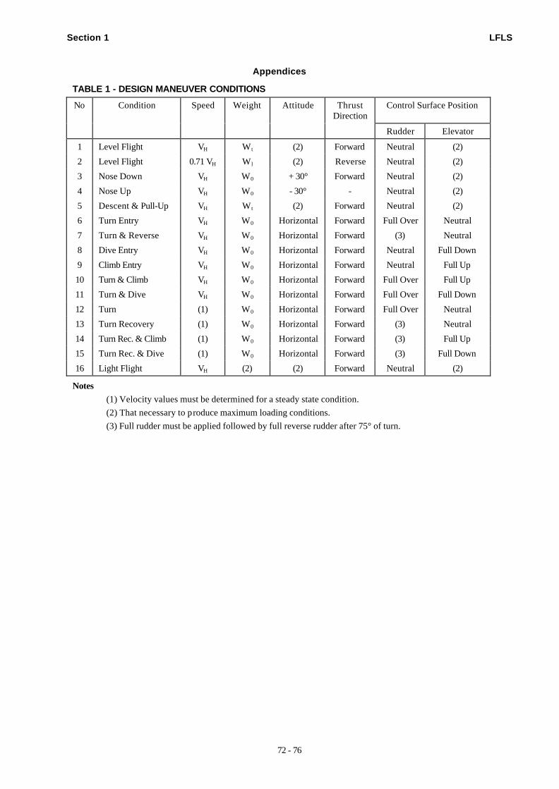
Section 1 LFLS
72 - 76
Appendices
TABLE 1 - DESIGN MANEUVER CONDITIONS
No Condition Speed Weight Attitude ThrustDirection
Control Surface Position
Rudder Elevator
1 Level Flight VH W t (2) Forward Neutral (2)
2 Level Flight 0.71 VH W l (2) Reverse Neutral (2)
3 Nose Down VH W0 + 30° Forward Neutral (2)
4 Nose Up VH W0 - 30° - Neutral (2)
5 Descent & Pull-Up VH W t (2) Forward Neutral (2)
6 Turn Entry VH W0 Horizontal Forward Full Over Neutral
7 Turn & Reverse VH W0 Horizontal Forward (3) Neutral
8 Dive Entry VH W0 Horizontal Forward Neutral Full Down
9 Climb Entry VH W0 Horizontal Forward Neutral Full Up
10 Turn & Climb VH W0 Horizontal Forward Full Over Full Up
11 Turn & Dive VH W0 Horizontal Forward Full Over Full Down
12 Turn (1) W0 Horizontal Forward Full Over Neutral
13 Turn Recovery (1) W0 Horizontal Forward (3) Neutral
14 Turn Rec. & Climb (1) W0 Horizontal Forward (3) Full Up
15 Turn Rec. & Dive (1) W0 Horizontal Forward (3) Full Down
16 Light Flight VH (2) (2) Forward Neutral (2)
Notes
(1) Velocity values must be determined for a steady state condition.
(2) That necessary to produce maximum loading conditions.
(3) Full rudder must be applied followed by full reverse rudder after 75° of turn.
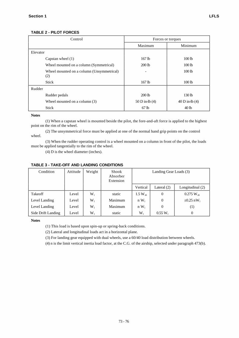
Section 1 LFLS
73 - 76
TABLE 2 - PILOT FORCES
Control Forces or torques
Maximum Minimum
Elevator
Capstan wheel (1) 167 lb 100 lb
Wheel mounted on a column (Symmetrical) 200 lb 100 lb
Wheel mounted on a column (Unsymmetrical)(2)
- 100 lb
Stick 167 lb 100 lb
Rudder
Rudder pedals 200 lb 130 lb
Wheel mounted on a column (3) 50 D in-lb (4) 40 D in-lb (4)
Stick 67 lb 40 lb
Notes
(1) When a capstan wheel is mounted beside the pilot, the fore-and-aft force is applied to the highestpoint on the rim of the wheel.
(2) The unsymmetrical force must be applied at one of the normal hand grip points on the controlwheel.
(3) When the rudder operating control is a wheel mounted on a column in front of the pilot, the loadsmust be applied tangentially to the rim of the wheel.
(4) D is the wheel diameter (inches).
TABLE 3 - TAKE-OFF AND LANDING CONDITIONS
Condition Attitude Weight ShookAbsorberExtension
Landing Gear Loads (3)
Vertical Lateral (2) Longitudinal (2)
Takeoff Level W t static 1.5 Wsh 0 0.275 Wsh
Level Landing Level W l Maximum n W l 0 ±0.25 nWl
Level Landing Level W l Maximum n W l 0 (1)
Side Drift Landing Level W l static W l 0.55 W l 0
Notes
(1) This load is based upon spin-up or spring-back conditions.
(2) Lateral and longitudinal loads act in a horizontal plane.
(3) For landing gear equipped with dual wheels, use a 60/40 load distribution between wheels.
(4) n is the limit vertical inertia load factor, at the C.G. of the airship, selected under paragraph 473(b).
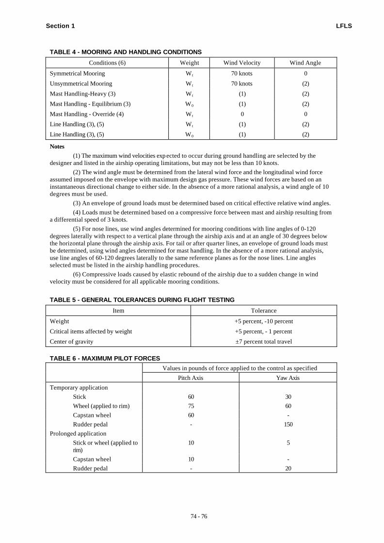
Section 1 LFLS
74 - 76
TABLE 4 - MOORING AND HANDLING CONDITIONS
Conditions (6) Weight Wind Velocity Wind Angle
Symmetrical Mooring W t 70 knots 0
Unsymmetrical Mooring W t 70 knots (2)
Mast Handling-Heavy (3) W t (1) (2)
Mast Handling - Equilibrium (3) W0 (1) (2)
Mast Handling - Override (4) W t 0 0
Line Handling (3), (5) W t (1) (2)
Line Handling (3), (5) W0 (1) (2)
Notes
(1) The maximum wind velocities exp ected to occur during ground handling are selected by thedesigner and listed in the airship operating limitations, but may not be less than 10 knots.
(2) The wind angle must be determined from the lateral wind force and the longitudinal wind forceassumed imposed on the envelope with maximum design gas pressure. These wind forces are based on aninstantaneous directional change to either side. In the absence of a more rational analysis, a wind angle of 10degrees must be used.
(3) An envelope of ground loads must be determined based on critical effective relative wind angles.
(4) Loads must be determined based on a compressive force between mast and airship resulting froma differential speed of 3 knots.
(5) For nose lines, use wind angles determined for mooring conditions with line angles of 0-120degrees laterally with respect to a vertical plane through the airship axis and at an angle of 30 degrees belowthe horizontal plane through the airship axis. For tail or after quarter lines, an envelope of ground loads mustbe determined, using wind angles determined for mast handling. In the absence of a more rational analysis,use line angles of 60-120 degrees laterally to the same reference planes as for the nose lines. Line anglesselected must be listed in the airship handling procedures.
(6) Compressive loads caused by elastic rebound of the airship due to a sudden change in windvelocity must be considered for all applicable mooring conditions.
TABLE 5 - GENERAL TOLERANCES DURING FLIGHT TESTING
Item Tolerance
Weight +5 percent, -10 percent
Critical items affected by weight +5 percent, - 1 percent
Center of gravity ±7 percent total travel
TABLE 6 - MAXIMUM PILOT FORCESValues in pounds of force applied to the control as specified
Pitch Axis Yaw Axis
Temporary application
Stick 60 30
Wheel (applied to rim) 75 60
Capstan wheel 60 -
Rudder pedal - 150
Prolonged application
Stick or wheel (applied torim)
10 5
Capstan wheel 10 -
Rudder pedal - 20
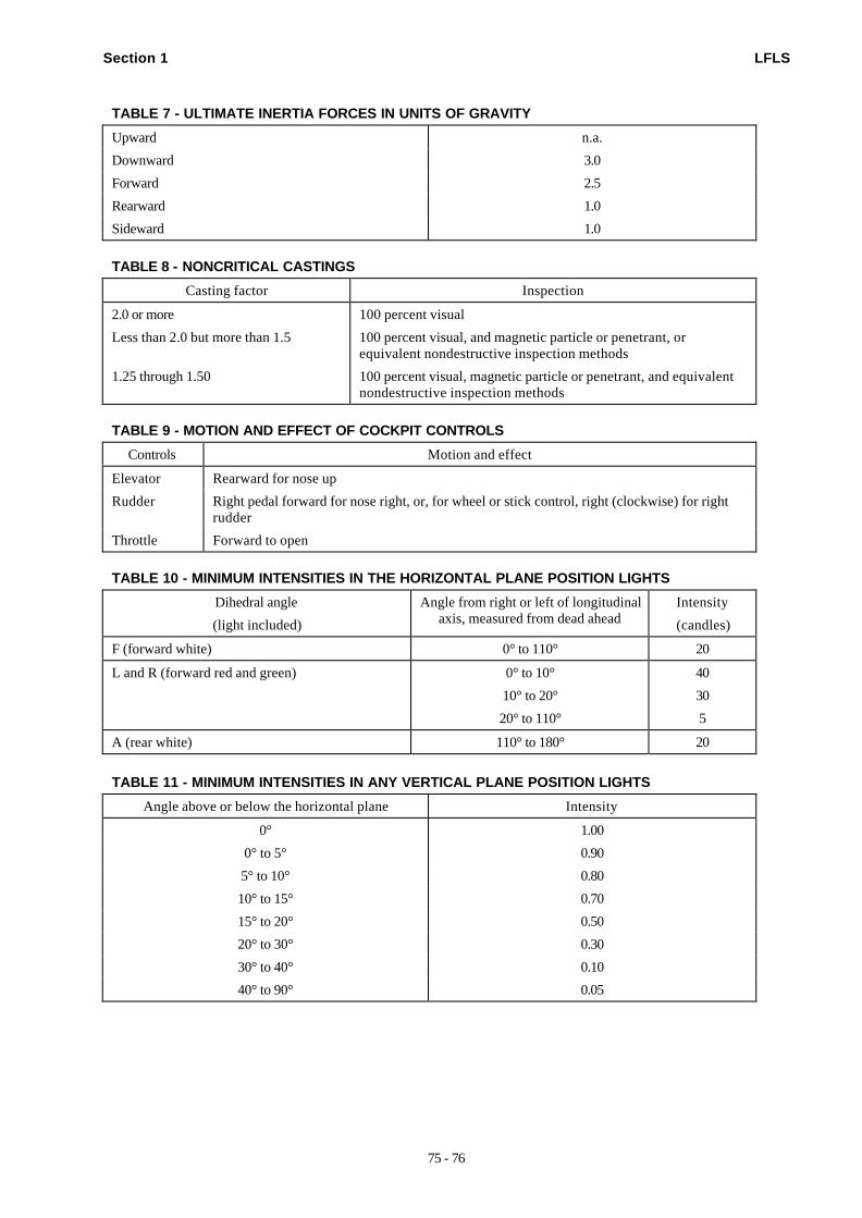
Section 1 LFLS
75 - 76
TABLE 7 - ULTIMATE INERTIA FORCES IN UNITS OF GRAVITY
Upward n.a.
Downward 3.0
Forward 2.5
Rearward 1.0
Sideward 1.0
TABLE 8 - NONCRITICAL CASTINGS
Casting factor Inspection
2.0 or more 100 percent visual
Less than 2.0 but more than 1.5 100 percent visual, and magnetic particle or penetrant, orequivalent nondestructive inspection methods
1.25 through 1.50 100 percent visual, magnetic particle or penetrant, and equivalentnondestructive inspection methods
TABLE 9 - MOTION AND EFFECT OF COCKPIT CONTROLS
Controls Motion and effect
Elevator Rearward for nose up
Rudder Right pedal forward for nose right, or, for wheel or stick control, right (clockwise) for rightrudder
Throttle Forward to open
TABLE 10 - MINIMUM INTENSITIES IN THE HORIZONTAL PLANE POSITION LIGHTS
Dihedral angle
(light included)
Angle from right or left of longitudinalaxis, measured from dead ahead
Intensity
(candles)
F (forward white) 0° to 110° 20
L and R (forward red and green) 0° to 10°
10° to 20°
20° to 110°
40
30
5
A (rear white) 110° to 180° 20
TABLE 11 - MINIMUM INTENSITIES IN ANY VERTICAL PLANE POSITION LIGHTS
Angle above or below the horizontal plane Intensity
0° 1.00
0° to 5° 0.90
5° to 10° 0.80
10° to 15° 0.70
15° to 20° 0.50
20° to 30° 0.30
30° to 40° 0.10
40° to 90° 0.05
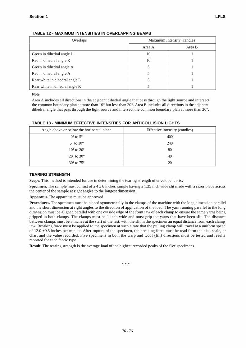
Section 1 LFLS
76 - 76
TABLE 12 - MAXIMUM INTENSITIES IN OVERLAPPING BEAMS
Overlaps Maximum Intensity (candles)
Area A Area B
Green in dihedral angle L 10 1
Red in dihedral angle R 10 1
Green in dihedral angle A 5 1
Red in dihedral angle A 5 1
Rear white in dihedral angle L 5 1
Rear white in dihedral angle R 5 1
Note
Area A includes all directions in the adjacent dihedral angle that pass through the light source and intersectthe common boundary plan at more than 10° but less than 20°. Area B includes all directions in the adjacentdihedral angle that pass through the light source and intersect the common boundary plan at more than 20°.
TABLE 13 - MINIMUM EFFECTIVE INTENSITIES FOR ANTICOLLISION LIGHTS
Angle above or below the horizontal plane Effective intensity (candles)
0° to 5° 400
5° to 10° 240
10° to 20° 80
20° to 30° 40
30° to 75° 20
TEARING STRENGTHScope. This method is intended for use in determining the tearing strength of envelope fabric.
Specimen. The sample must consist of a 4 x 6 inches sample having a 1.25 inch wide slit made with a razor blade acrossthe center of the sample at right angles to the longest dimension.
Apparatus. The apparatus must be approved.
Procedures. The specimen must be placed symmetrically in the clamps of the machine with the long dimension paralleland the short dimension at right angles to the direction of application of the load. The yarn running parallel to the longdimension must be aligned parallel with one outside edge of the front jaw of each clamp to ensure the same yarns beinggripped in both clamps. The clamps must be 1 inch wide and must grip the yarns that have been slit. The distancebetween clamps must be 3 inches at the start of the test, with the slit in the specimen an equal distance from each clampjaw. Breaking force must be applied to the specimen at such a rate that the pulling clamp will travel at a uniform speedof 12.0 ±0.5 inches per minute. After rupture of the specimen, the breaking force must be read form the dial, scale, orchart and the value recorded. Five specimens in both the warp and woof (fill) directions must be tested and resultsreported for each fabric type.
Result. The tearing strength is the average load of the highest recorded peaks of the five specimens.
* * *