Embed Size (px)
DESCRIPTION
Â
Citation preview
render(s) of building
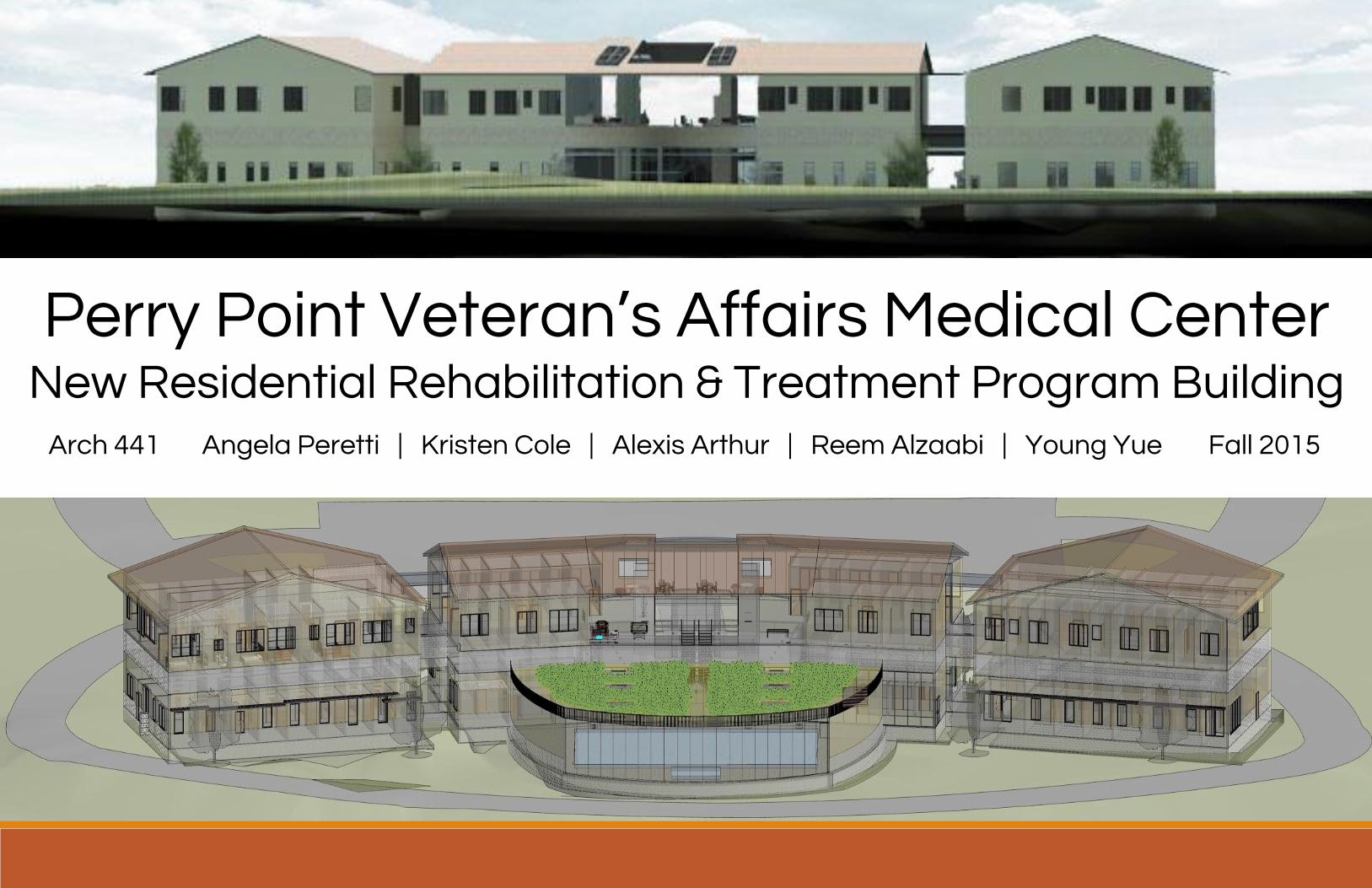
Perry Point Veteran’s Affairs Medical Center
Angela Peretti | Kristen Cole | Alexis Arthur | Reem Alzaabi | Young YueArch 441
New Residential Rehabilitation & Treatment Program BuildingFall 2015
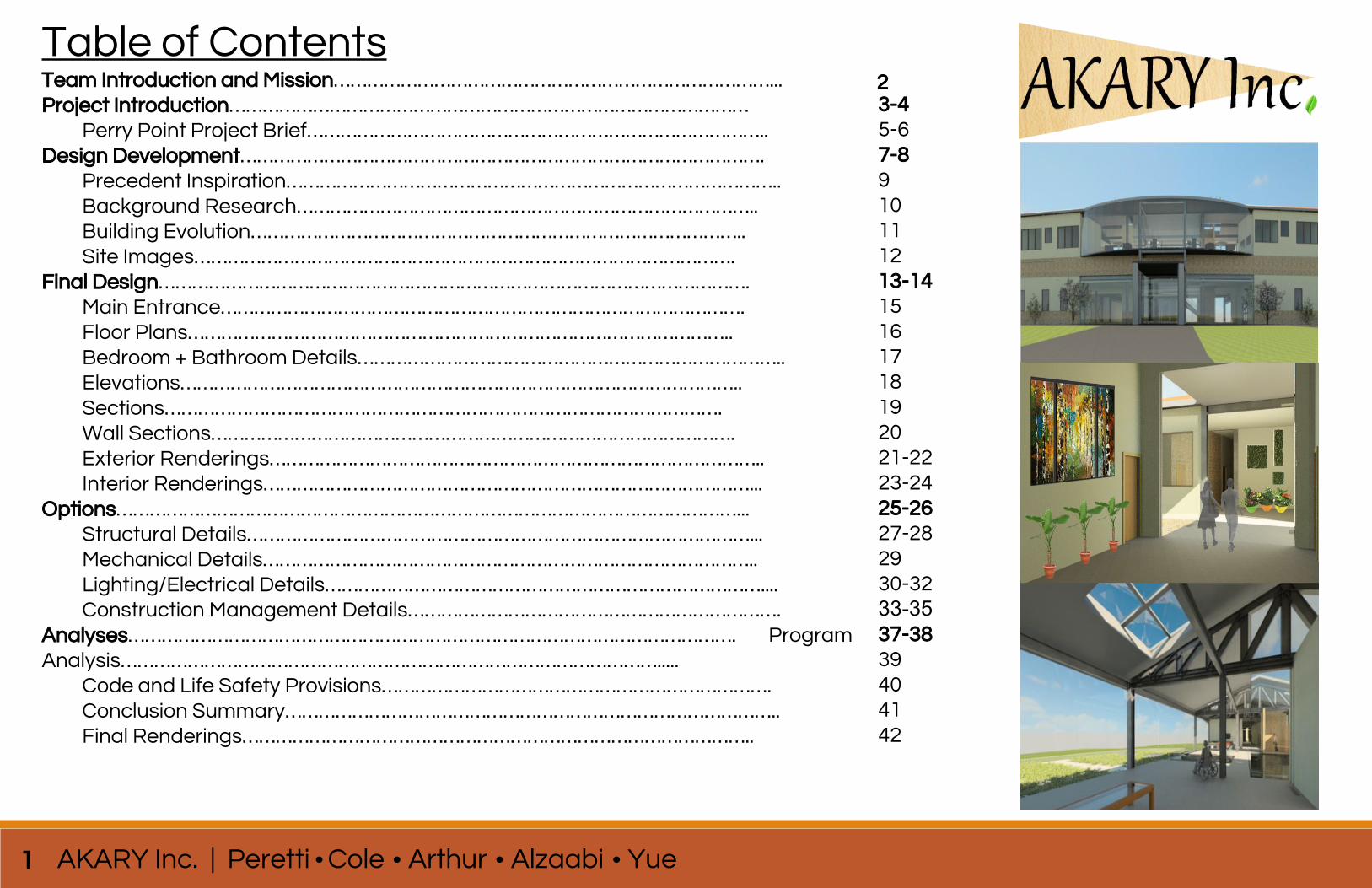
Table of ContentsTeam Introduction and Mission……………………………………………………………………...Project Introduction…………………………………………………………………………………
Perry Point Project Brief………………………………………………………………………..Design Development………………………………………………………………………………….
Precedent Inspiration……………………………………………………………………………..Background Research………………………………………………………………………..Building Evolution……………………………………………………………………………..Site Images…………………………………………………………………………………….
Final Design…………………………………………………………………………………………….Main Entrance………………………………………………………………………………….Floor Plans……………………………………………………………………………………..Bedroom + Bathroom Details…………………………………………………………………..Elevations………………………………………………………………………………………..Sections……………………………………………………………………………………….Wall Sections………………………………………………………………………………….Exterior Renderings……………………………………………………………………………..Interior Renderings……………………………………………………………………………...
Options…………………………………………………………………………………………………...Structural Details………………………………………………………………………………...Mechanical Details……………………………………………………………………………..Lighting/Electrical Details……………………………………………………………………....Construction Management Details………………………………………………………….
Analyses………………………………………………………………………………………………. Program Analysis…………………………………………………………………………………….....
Code and Life Safety Provisions…………………………………………………………….Conclusion Summary……………………………………………………………………………..Final Renderings………………………………………………………………………………..
3-45-67-8910111213-1415161718192021-2223-2425-2627-282930-3233-3537-3839404142
1 AKARY Inc. | Peretti Cole Arthur Alzaabi Yue
2
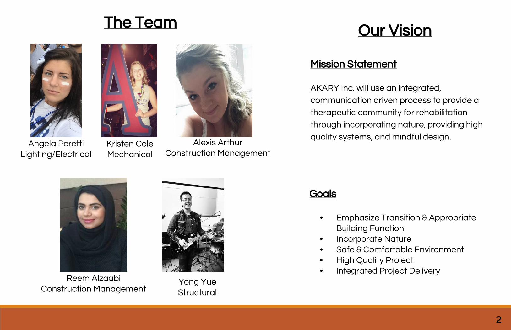
Angela PerettiLighting/Electrical
Kristen ColeMechanical
Alexis ArthurConstruction Management
Reem AlzaabiConstruction Management
Yong YueStructural
The Team Our Vision
Mission Statement
AKARY Inc. will use an integrated,
communication driven process to provide a
therapeutic community for rehabilitation
through incorporating nature, providing high
quality systems, and mindful design.
Goals
• Emphasize Transition & Appropriate Building Function
• Incorporate Nature• Safe & Comfortable Environment• High Quality Project• Integrated Project Delivery
2
Department of Veteran’s Affairs
Perry Point Medical Center
Residential Rehabilitation & Treatment Program Building
3 AKARY Inc. | Peretti Cole Arthur Alzaabi Yue

Introduction
4
Pe
rry
Po
int
Pro
jec
t B
rie
f
5 AKARY Inc. | Peretti Cole Arthur Alzaabi Yue
6
AKARY Inc. | Peretti Cole Arthur Alzaabi Yue
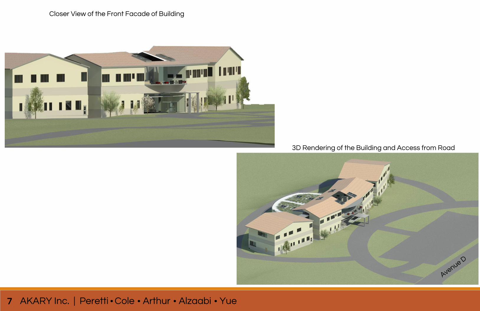
3D Rendering of the Building and Access from Road
Avenue D
Closer View of the Front Facade of Building
7

Design Development
8
Pre
ce
de
nt
Insp
ira
tio
n
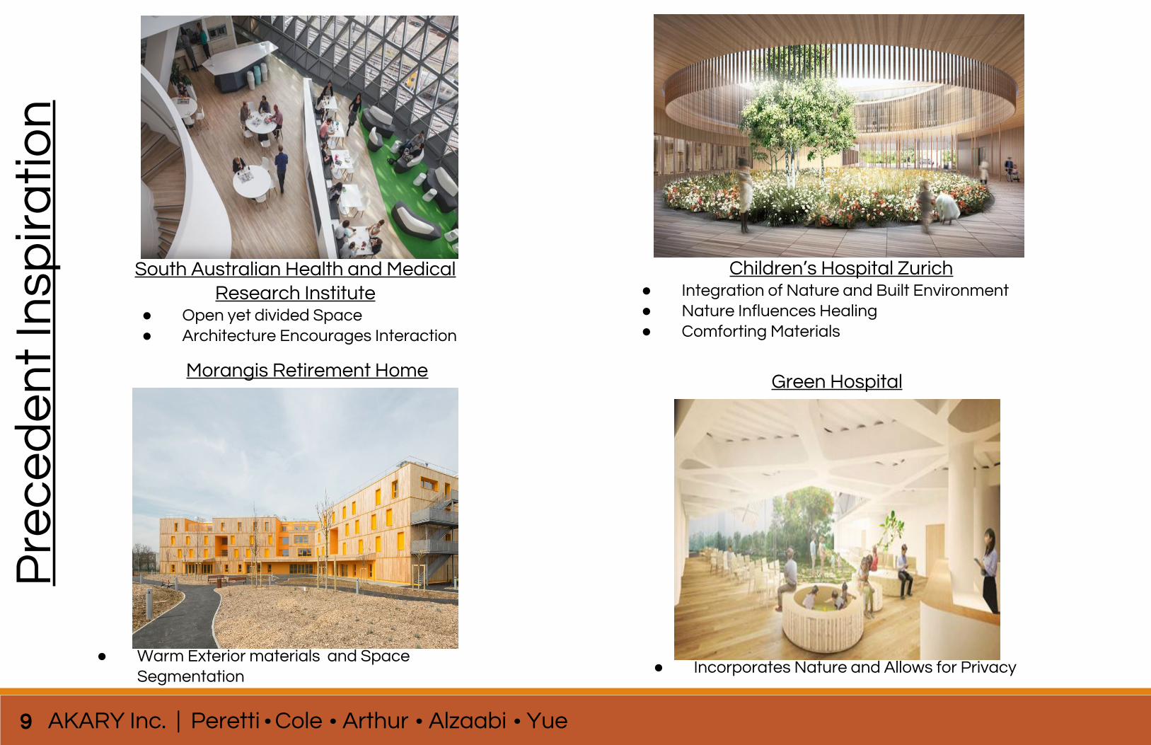
South Australian Health and Medical Research Institute
● Open yet divided Space● Architecture Encourages Interaction
Children’s Hospital Zurich● Integration of Nature and Built Environment● Nature Influences Healing● Comforting Materials
Morangis Retirement Home
● Warm Exterior materials and Space Segmentation
Green Hospital
● Incorporates Nature and Allows for Privacy
9 AKARY Inc. | Peretti Cole Arthur Alzaabi Yue
Background research- including pictures of buildings near site, history of site etc
climate analysis of perry point- rainfall temperature wind etc
Ba
ckg
rou
nd
Re
sea
rch
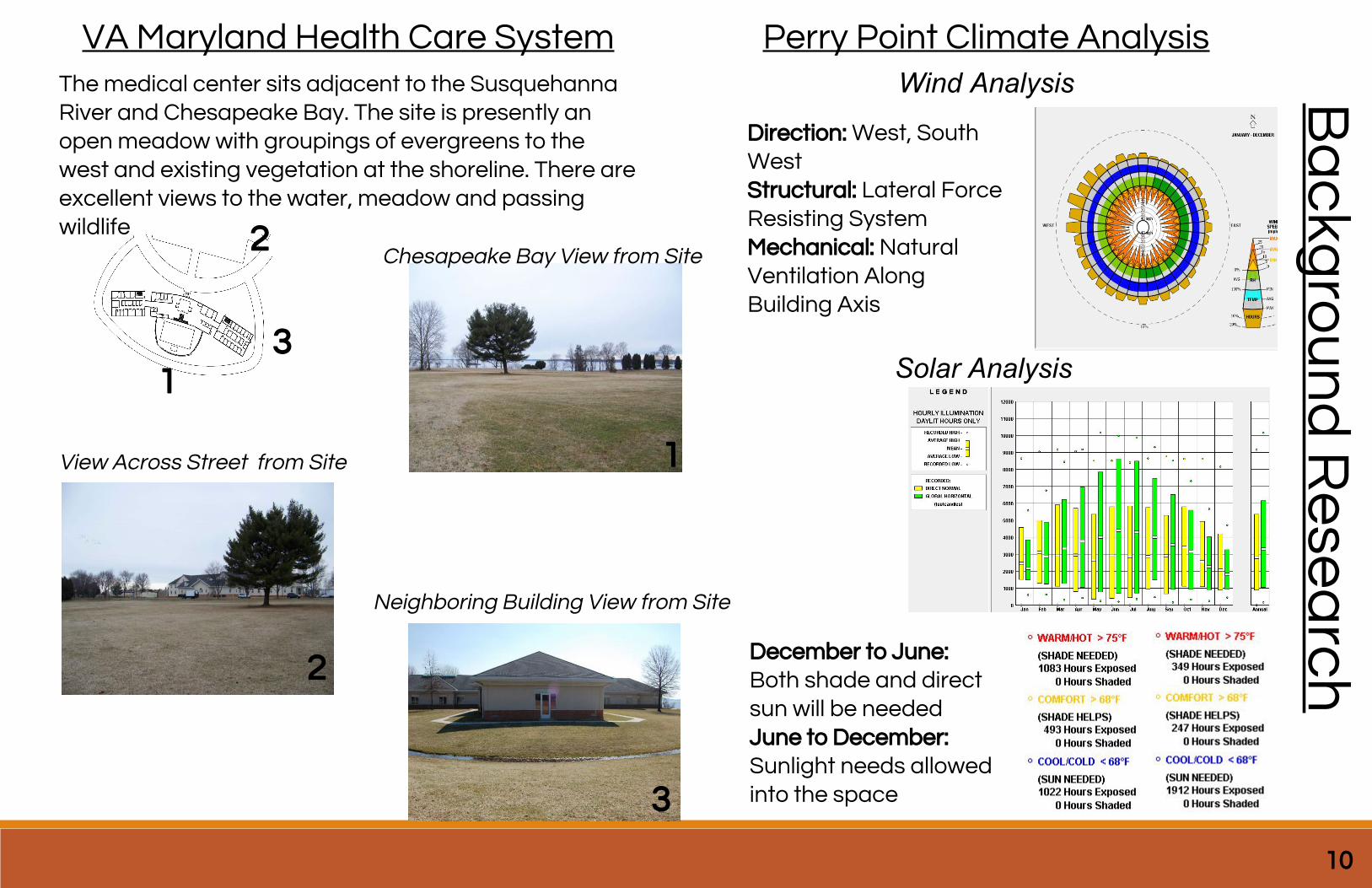
VA Maryland Health Care System
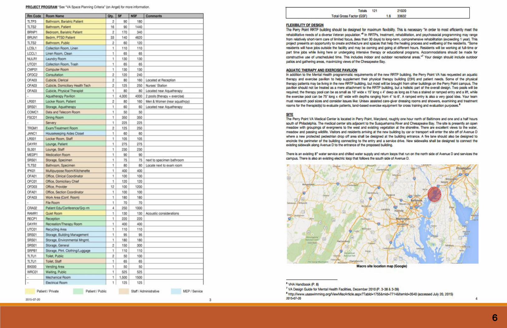
The medical center sits adjacent to the Susquehanna River and Chesapeake Bay. The site is presently an open meadow with groupings of evergreens to the west and existing vegetation at the shoreline. There are excellent views to the water, meadow and passing wildlife
Perry Point Climate Analysis
1
2
3
1
2
3
Chesapeake Bay View from Site
View Across Street from Site
Neighboring Building View from Site
Direction: West, South WestStructural: Lateral Force Resisting System Mechanical: Natural Ventilation Along Building Axis
Wind Analysis
Solar Analysis
10
December to June:Both shade and direct sun will be neededJune to December: Sunlight needs allowed into the space
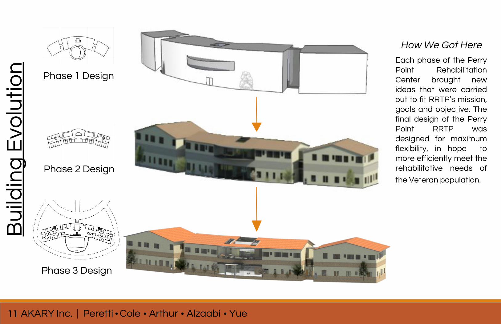
Building Evolution- use sketches/models to show how the building design progressed. Use minimal text to describe
Bu
ildin
g E
volu
tio
n Phase 1 Design
Phase 2 Design
Each phase of the Perry Point Rehabilitation Center brought new ideas that were carried out to fit RRTP’s mission, goals and objective. The final design of the Perry Point RRTP was designed for maximum flexibility, in hope to more efficiently meet the rehabilitative needs of
the Veteran population.
How We Got Here
Phase 3 Design
11 AKARY Inc. | Peretti Cole Arthur Alzaabi Yue
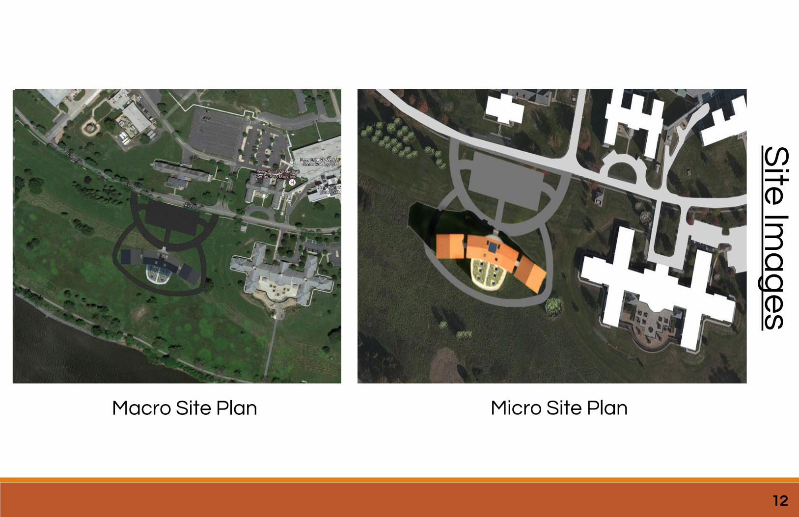
Macro Site Plan Micro Site Plan
Site
Ima
ge
s
12
Four Images to show what’s to come
13 AKARY Inc. | Peretti Cole Arthur Alzaabi Yue
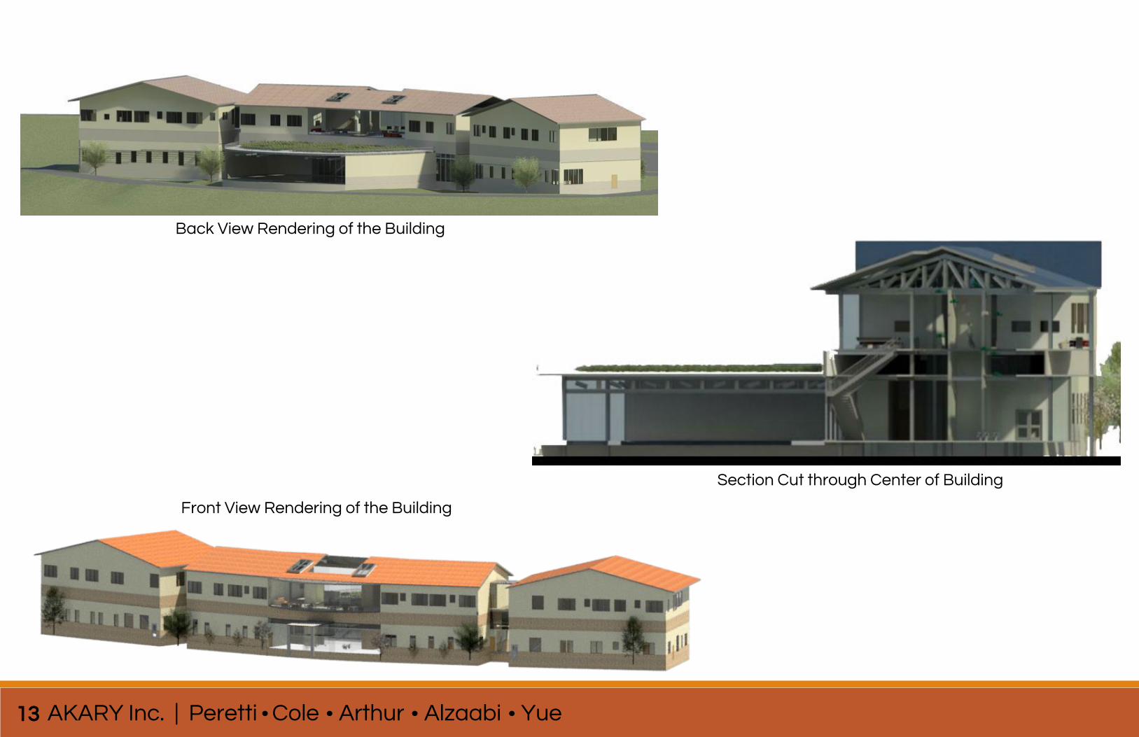
Section Cut through Center of Building
Back View Rendering of the Building
Front View Rendering of the Building

Final Design
14
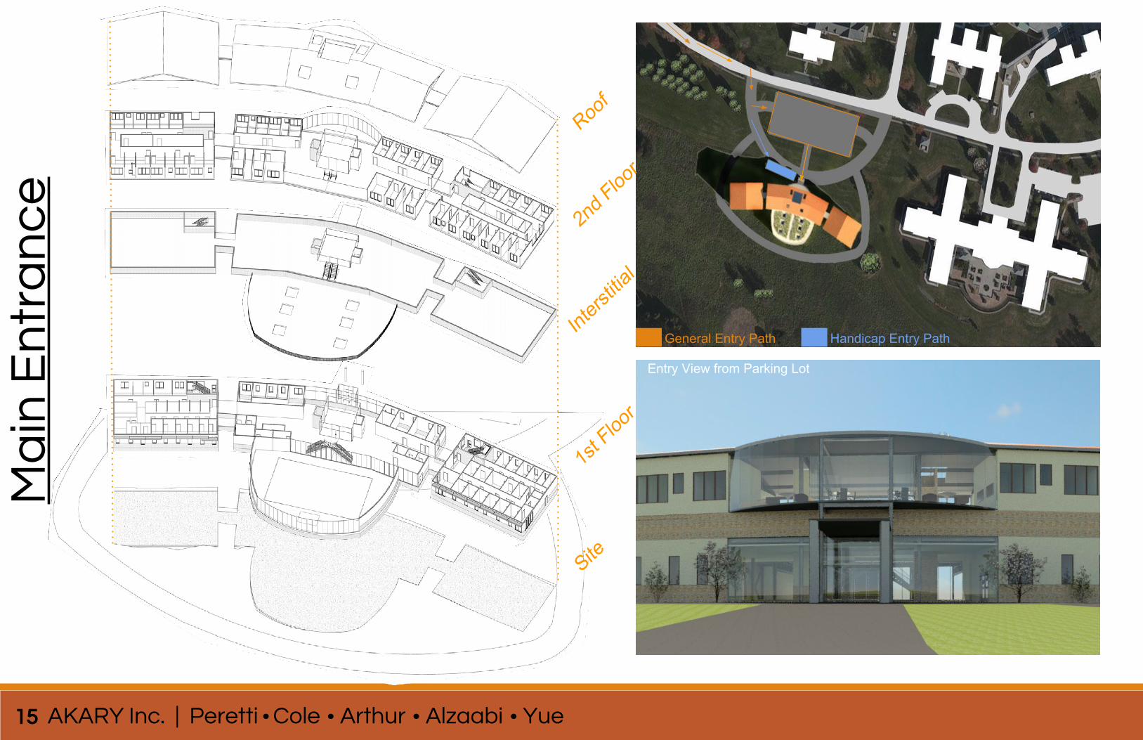
General Entry Path Handicap Entry Path
Entry View from Parking Lot
Roof
2nd F
loor
Inters
titial
Site
1st F
loor
15 AKARY Inc. | Peretti Cole Arthur Alzaabi Yue
Ma
in E
ntr
an
ce
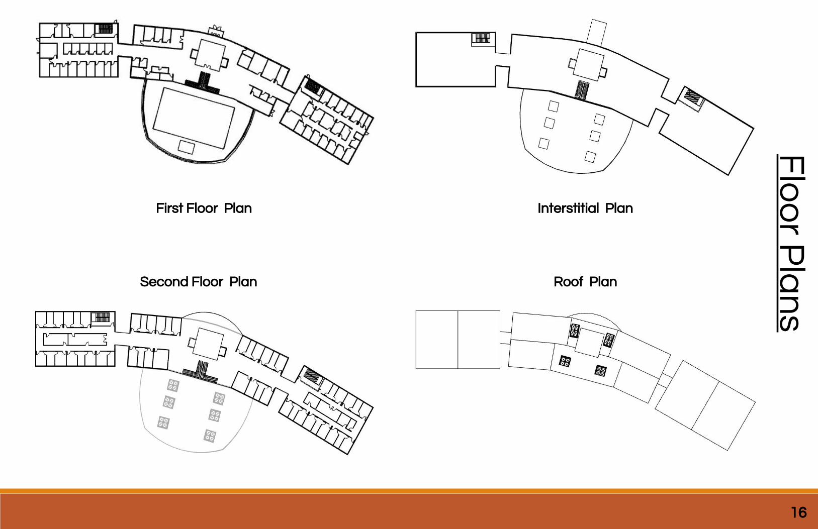
Interstitial Plan
Roof Plan
16
Flo
or P
lan
s
First Floor Plan
Second Floor Plan
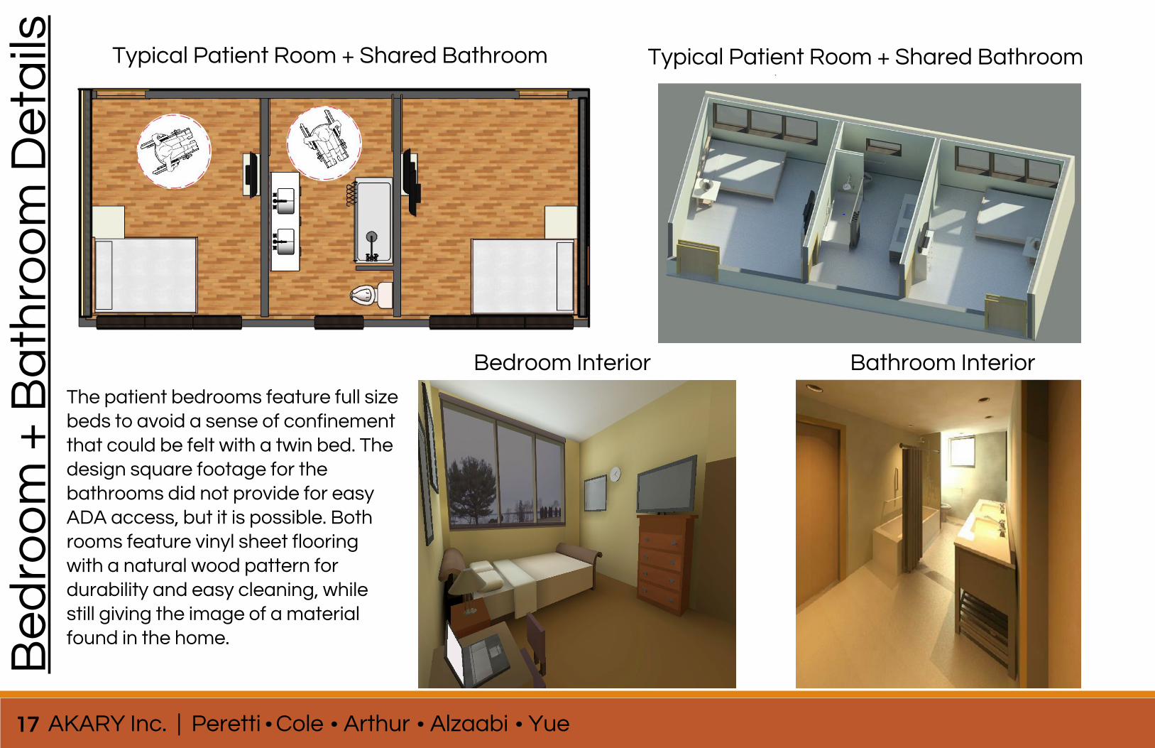
Bedroom Interior
Typical Patient Room + Shared Bathroom
17 AKARY Inc. | Peretti Cole Arthur Alzaabi Yue
Be
dro
om
+ B
ath
roo
m D
eta
ils
Typical Patient Room + Shared Bathroom
Bathroom Interior
The patient bedrooms feature full size beds to avoid a sense of confinement that could be felt with a twin bed. The design square footage for the bathrooms did not provide for easy ADA access, but it is possible. Both rooms feature vinyl sheet flooring with a natural wood pattern for durability and easy cleaning, while still giving the image of a material found in the home.
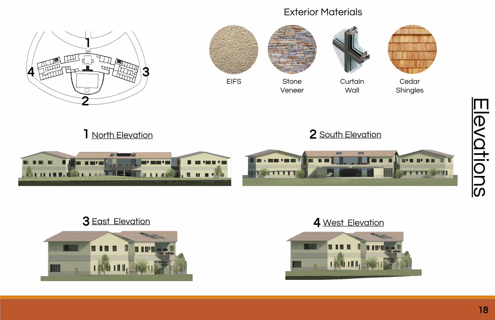
Key Plan showing elevation arrows
North Elevation
Exterior Materials
EIFS StoneVeneer
CurtainWall
CedarShingles
South Elevation
West ElevationEast Elevation
Ele
vatio
ns
1
3
2
4
1 2
3 4
18
19 AKARY Inc. | Peretti Cole Arthur Alzaabi Yue
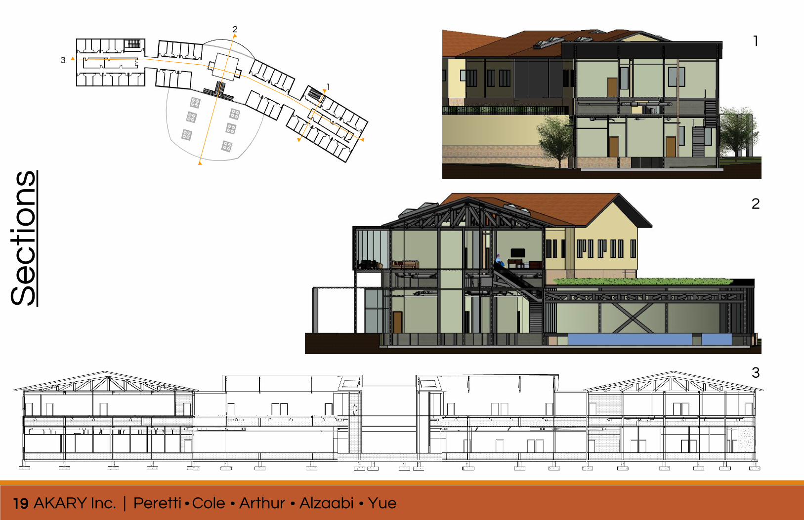
Se
cti
on
s2
1
3
1
2
3
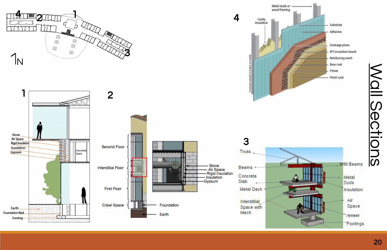
All 4 Finalized Wall Sections
-show key plans where cuts are made-use text describing the wall section/assembly
20
Wa
ll Se
ctio
ns
N
1
1
2
2
3
3
44
exterior renderings-be sure that all renderings have accompanied text, describing what picture is
21 AKARY Inc. | Peretti Cole Arthur Alzaabi Yue
Ext
eri
or
Re
nd
eri
ng
s
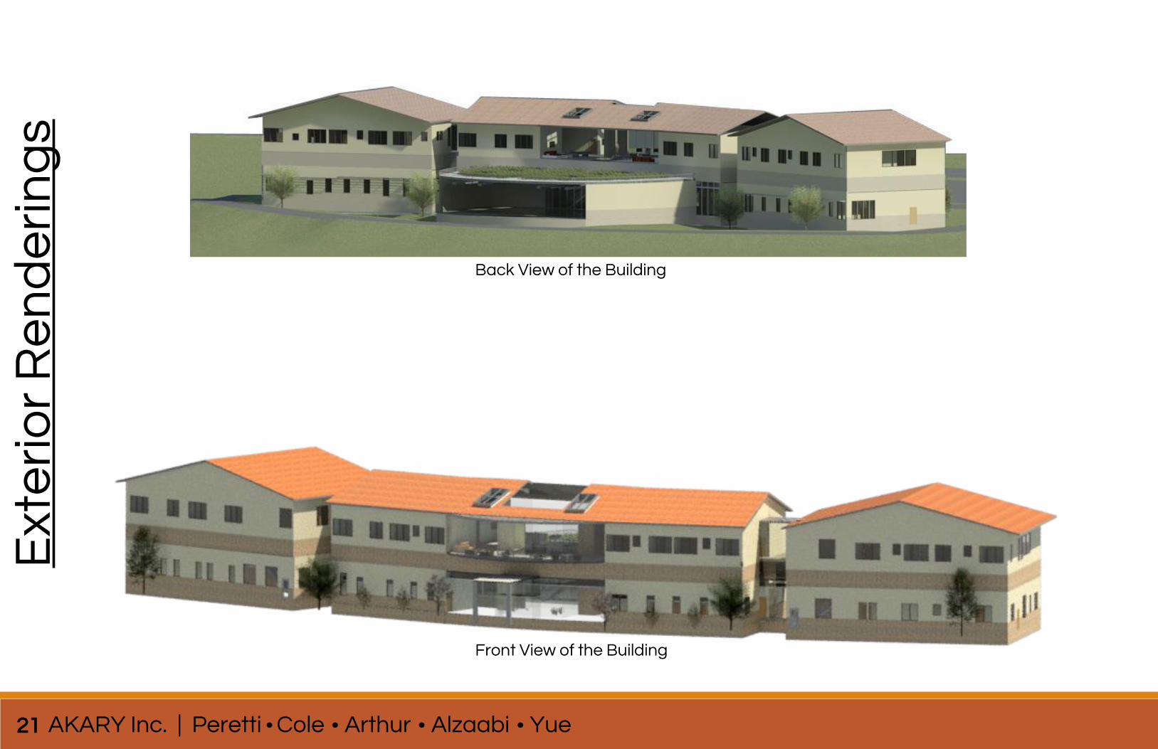
Back View of the Building
Front View of the Building
more exterior renderings-be sure that all renderings have accompanied text
22
Exte
rior R
en
de
ring
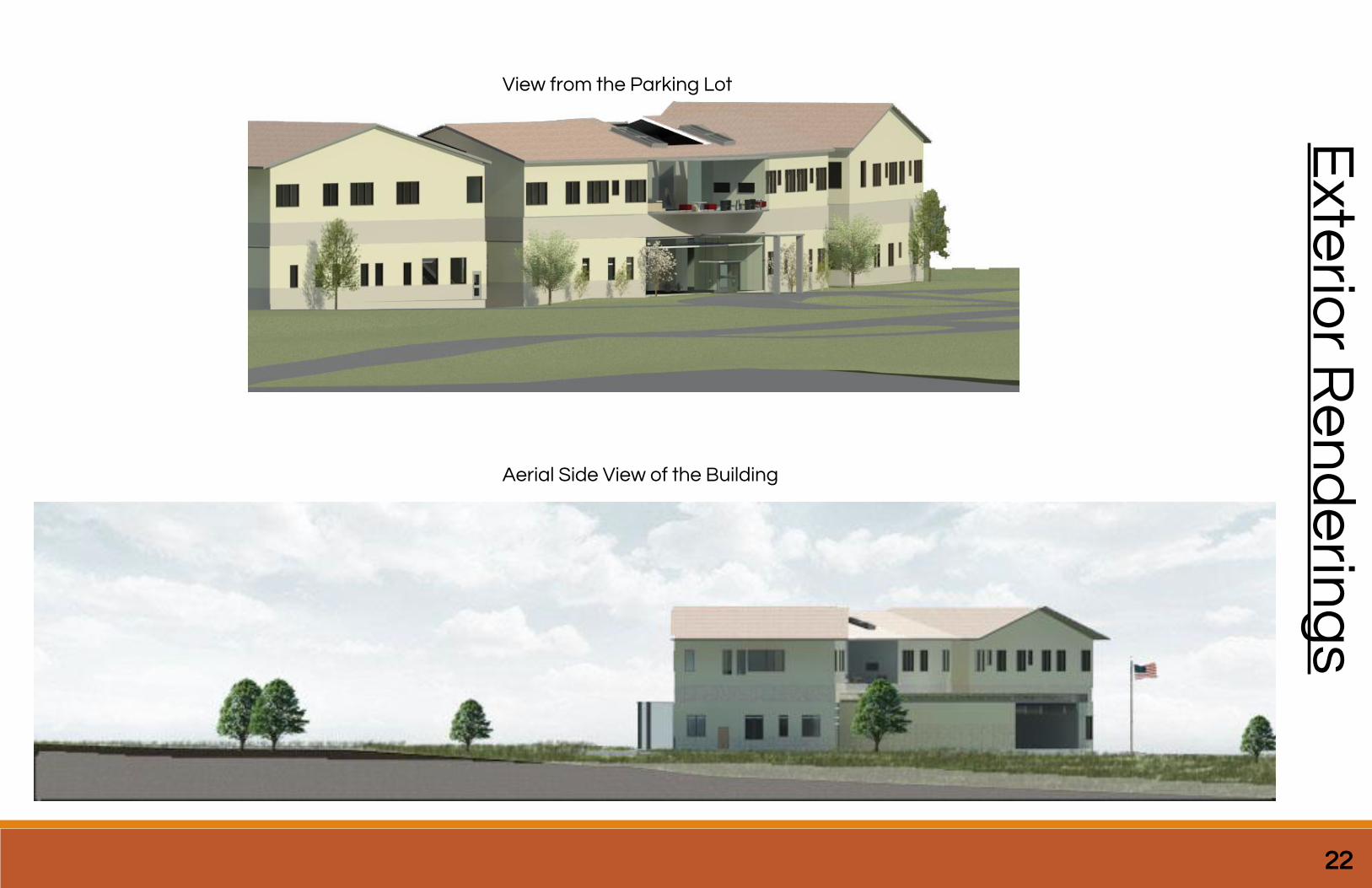
sView from the Parking Lot
Aerial Side View of the Building
23 AKARY Inc. | Peretti Cole Arthur Alzaabi Yue
Inte
rio
r R
en
de
rin
gs
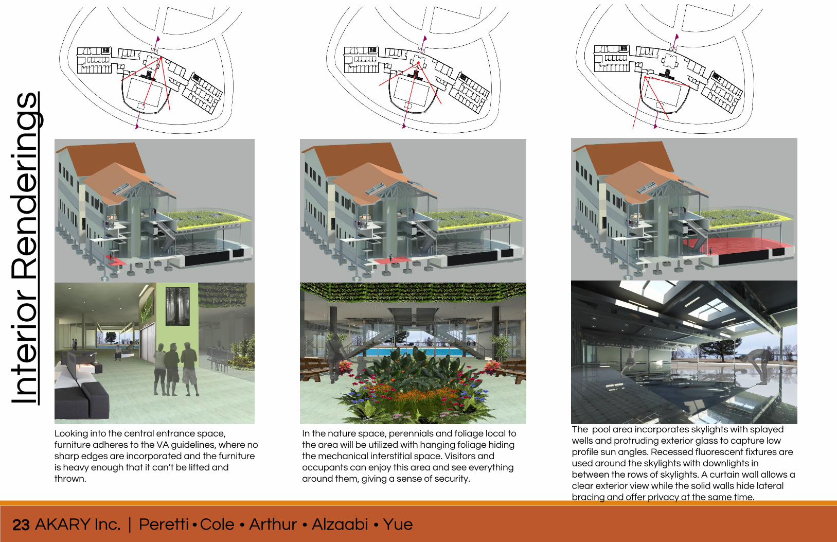
Looking into the central entrance space, furniture adheres to the VA guidelines, where no sharp edges are incorporated and the furniture is heavy enough that it can’t be lifted and thrown.
In the nature space, perennials and foliage local to the area will be utilized with hanging foliage hiding the mechanical interstitial space. Visitors and occupants can enjoy this area and see everything around them, giving a sense of security.
The pool area incorporates skylights with splayed wells and protruding exterior glass to capture low profile sun angles. Recessed fluorescent fixtures are used around the skylights with downlights in between the rows of skylights. A curtain wall allows a clear exterior view while the solid walls hide lateral bracing and offer privacy at the same time.
24
Inte
rior R
en
de
ring
s
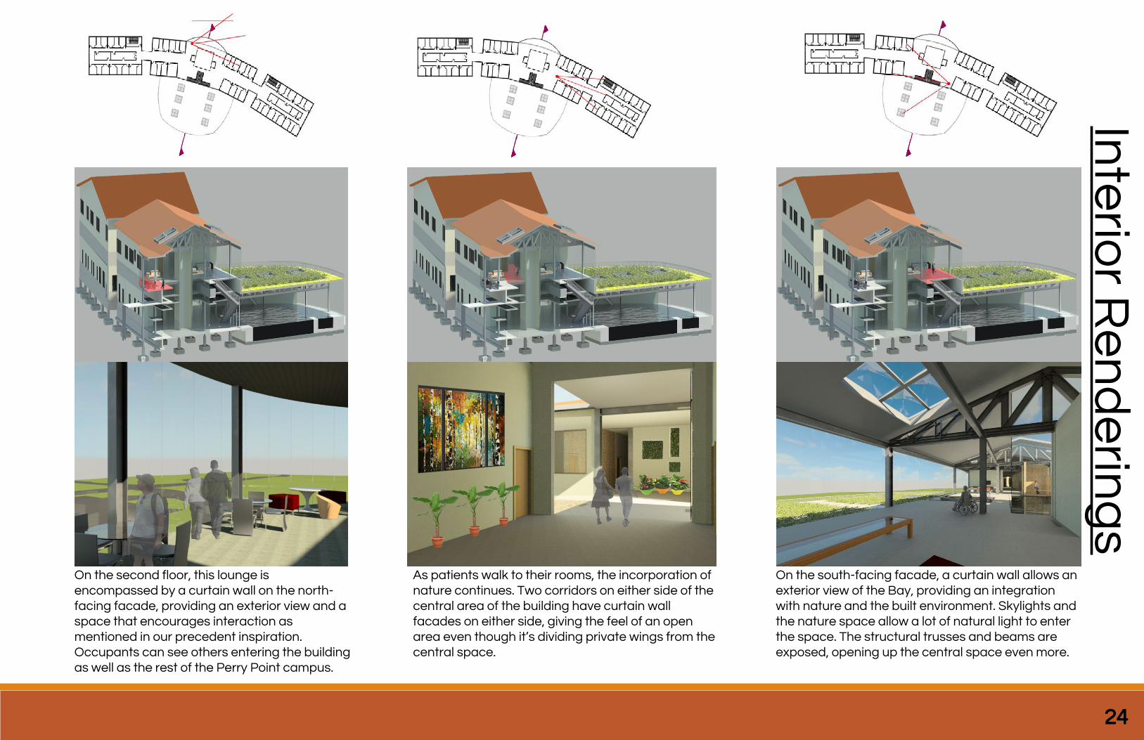
On the second floor, this lounge is encompassed by a curtain wall on the north-facing facade, providing an exterior view and a space that encourages interaction as mentioned in our precedent inspiration. Occupants can see others entering the building as well as the rest of the Perry Point campus.
As patients walk to their rooms, the incorporation of nature continues. Two corridors on either side of the central area of the building have curtain wall facades on either side, giving the feel of an open area even though it’s dividing private wings from the central space.
On the south-facing facade, a curtain wall allows an exterior view of the Bay, providing an integration with nature and the built environment. Skylights and the nature space allow a lot of natural light to enter the space. The structural trusses and beams are exposed, opening up the central space even more.
25 AKARY Inc. | Peretti Cole Arthur Alzaabi Yue
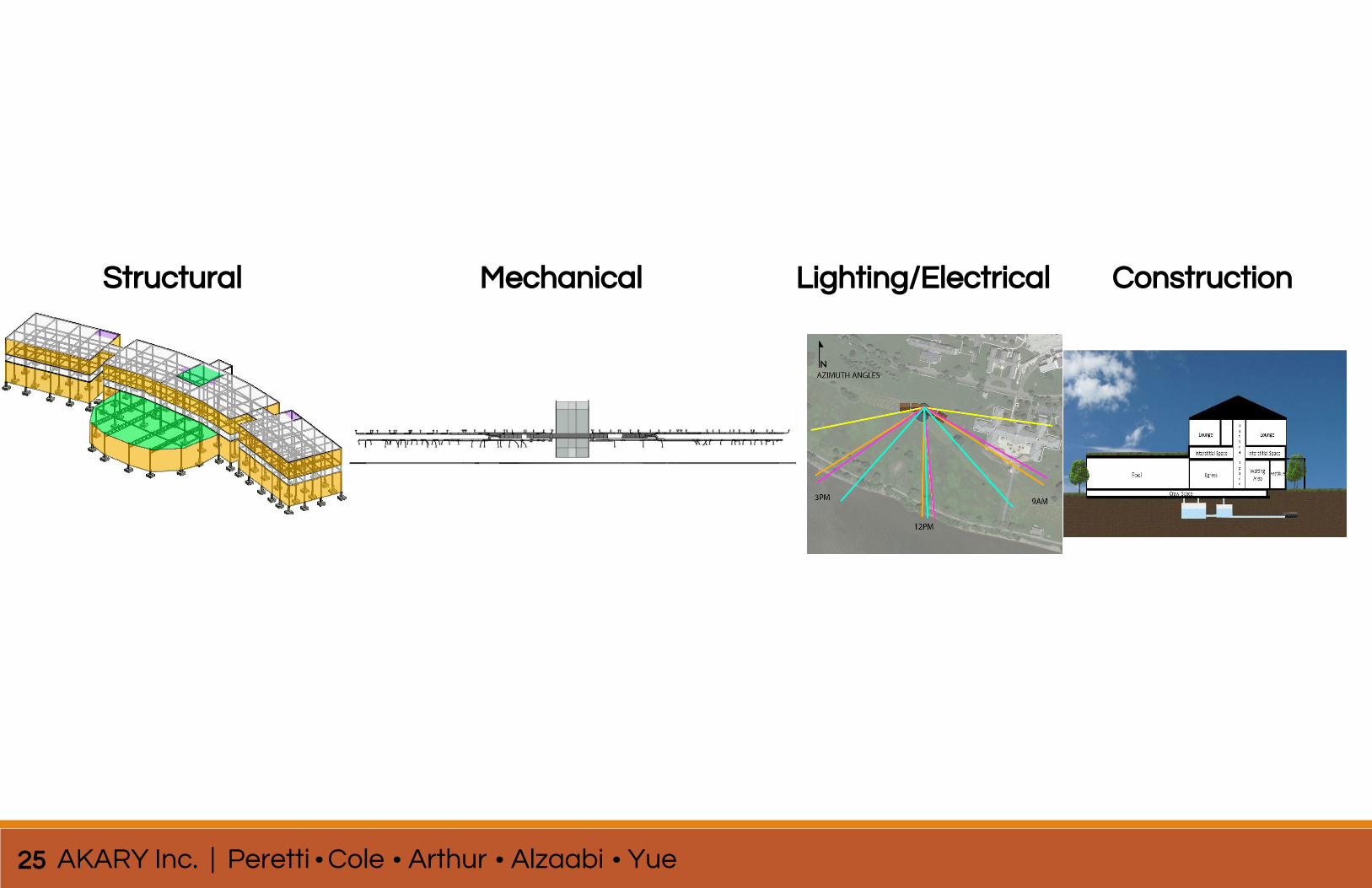
Structural Mechanical Lighting/Electrical Construction

Options
26
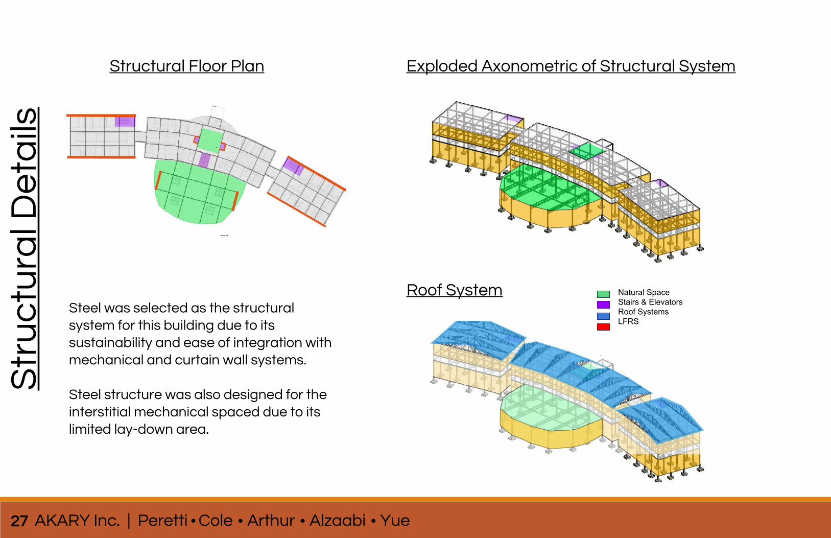
Structural Floor Plan Exploded Axonometric of Structural System
Steel was selected as the structural system for this building due to its sustainability and ease of integration with mechanical and curtain wall systems.
Steel structure was also designed for the interstitial mechanical spaced due to its limited lay-down area.
Str
uc
tura
l De
tails
Natural SpaceStairs & ElevatorsRoof SystemsLFRS
Roof System
27 AKARY Inc. | Peretti Cole Arthur Alzaabi Yue
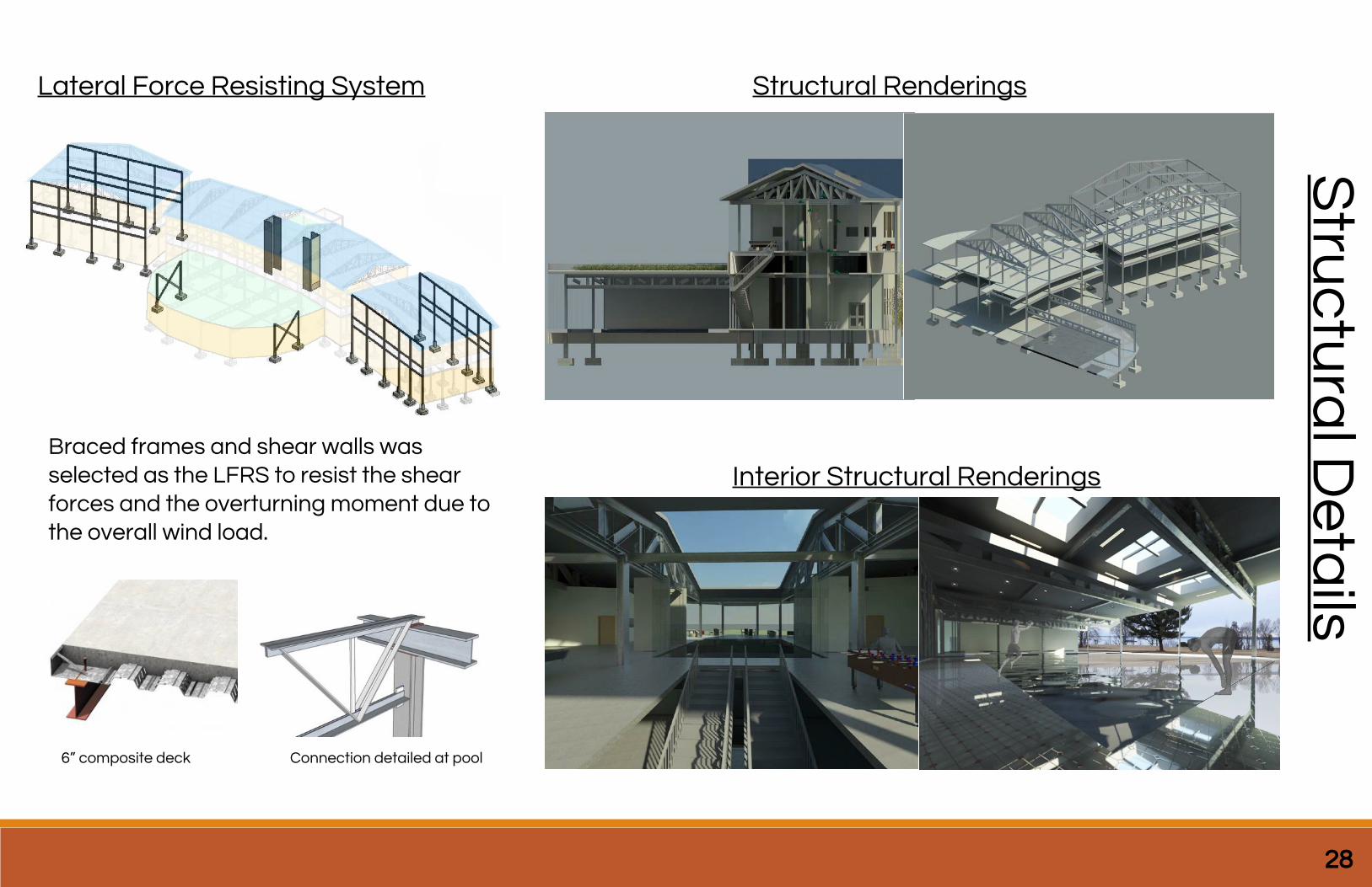
Lateral Force Resisting System Structural Renderings
Braced frames and shear walls was selected as the LFRS to resist the shear forces and the overturning moment due to the overall wind load.
6” composite deck Connection detailed at pool
Interior Structural Renderings
28
Stru
ctu
ral D
eta
ils
29 AKARY Inc. | Peretti Cole Arthur Alzaabi Yue
Me
ch
an
ica
l De
tails
Air Handling Unit
DOAS Unit
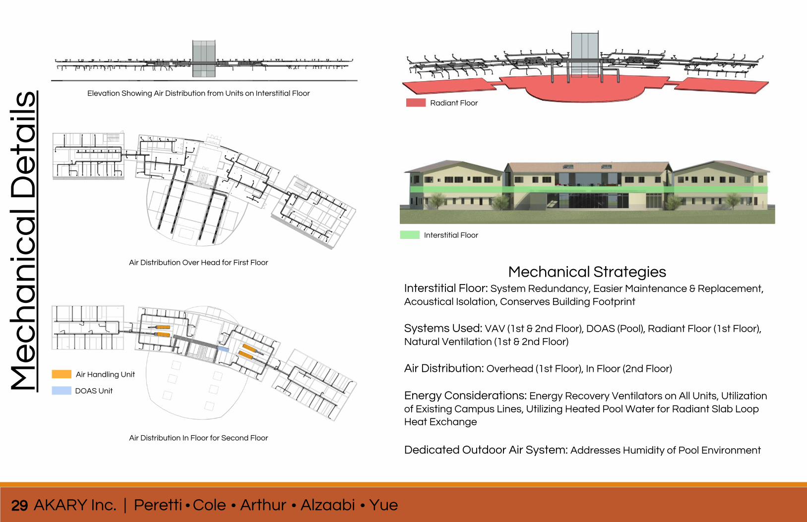
Radiant FloorElevation Showing Air Distribution from Units on Interstitial Floor
Air Distribution Over Head for First Floor
Air Distribution In Floor for Second Floor
Interstitial Floor
Mechanical StrategiesInterstitial Floor: System Redundancy, Easier Maintenance & Replacement, Acoustical Isolation, Conserves Building Footprint
Systems Used: VAV (1st & 2nd Floor), DOAS (Pool), Radiant Floor (1st Floor), Natural Ventilation (1st & 2nd Floor)
Air Distribution: Overhead (1st Floor), In Floor (2nd Floor)
Energy Considerations: Energy Recovery Ventilators on All Units, Utilization of Existing Campus Lines, Utilizing Heated Pool Water for Radiant Slab Loop Heat Exchange
Dedicated Outdoor Air System: Addresses Humidity of Pool Environment
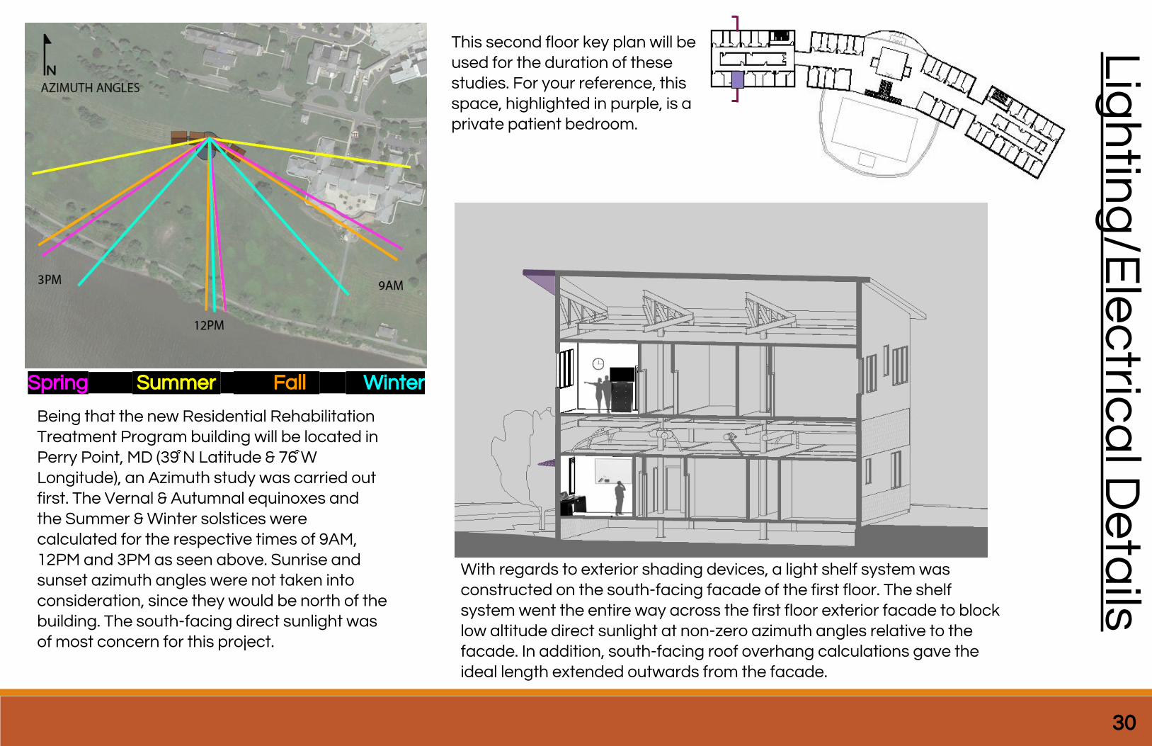
Spring Summer Fall Winter
Being that the new Residential Rehabilitation Treatment Program building will be located in Perry Point, MD (39͒ N Latitude & 76͒ W Longitude), an Azimuth study was carried out first. The Vernal & Autumnal equinoxes and the Summer & Winter solstices were calculated for the respective times of 9AM, 12PM and 3PM as seen above. Sunrise and sunset azimuth angles were not taken into consideration, since they would be north of the building. The south-facing direct sunlight was of most concern for this project.
This second floor key plan will be used for the duration of these studies. For your reference, this space, highlighted in purple, is a private patient bedroom.
With regards to exterior shading devices, a light shelf system was constructed on the south-facing facade of the first floor. The shelf system went the entire way across the first floor exterior facade to block low altitude direct sunlight at non-zero azimuth angles relative to the facade. In addition, south-facing roof overhang calculations gave the ideal length extended outwards from the facade.
30
Lig
htin
g/E
lec
trica
l De
tails
31 AKARY Inc. | Peretti Cole Arthur Alzaabi Yue
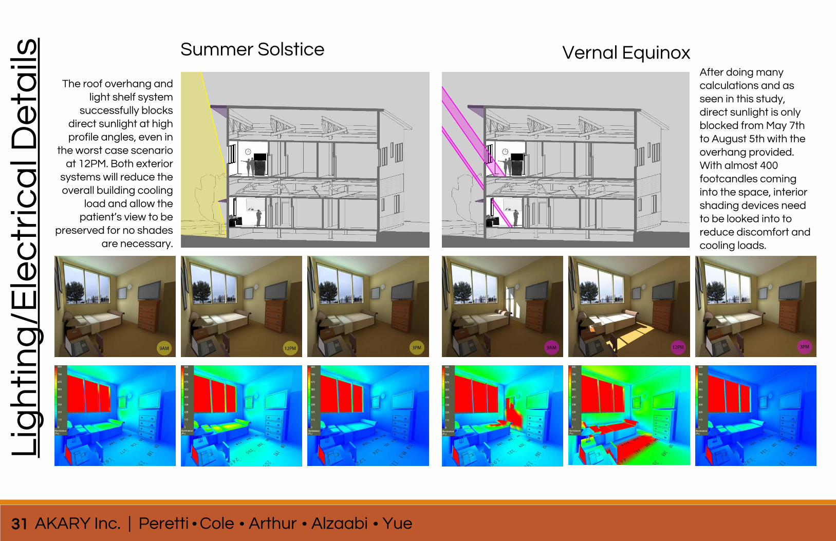
Summer Solstice Vernal Equinox
The roof overhang and light shelf system
successfully blocks direct sunlight at high profile angles, even in
the worst case scenario at 12PM. Both exterior
systems will reduce the overall building cooling
load and allow the patient’s view to be
preserved for no shades are necessary.
After doing many calculations and as seen in this study, direct sunlight is only blocked from May 7th to August 5th with the overhang provided. With almost 400 footcandles coming into the space, interior shading devices need to be looked into to reduce discomfort and cooling loads.
Lig
hti
ng
/Ele
ctr
ica
l De
tails
32
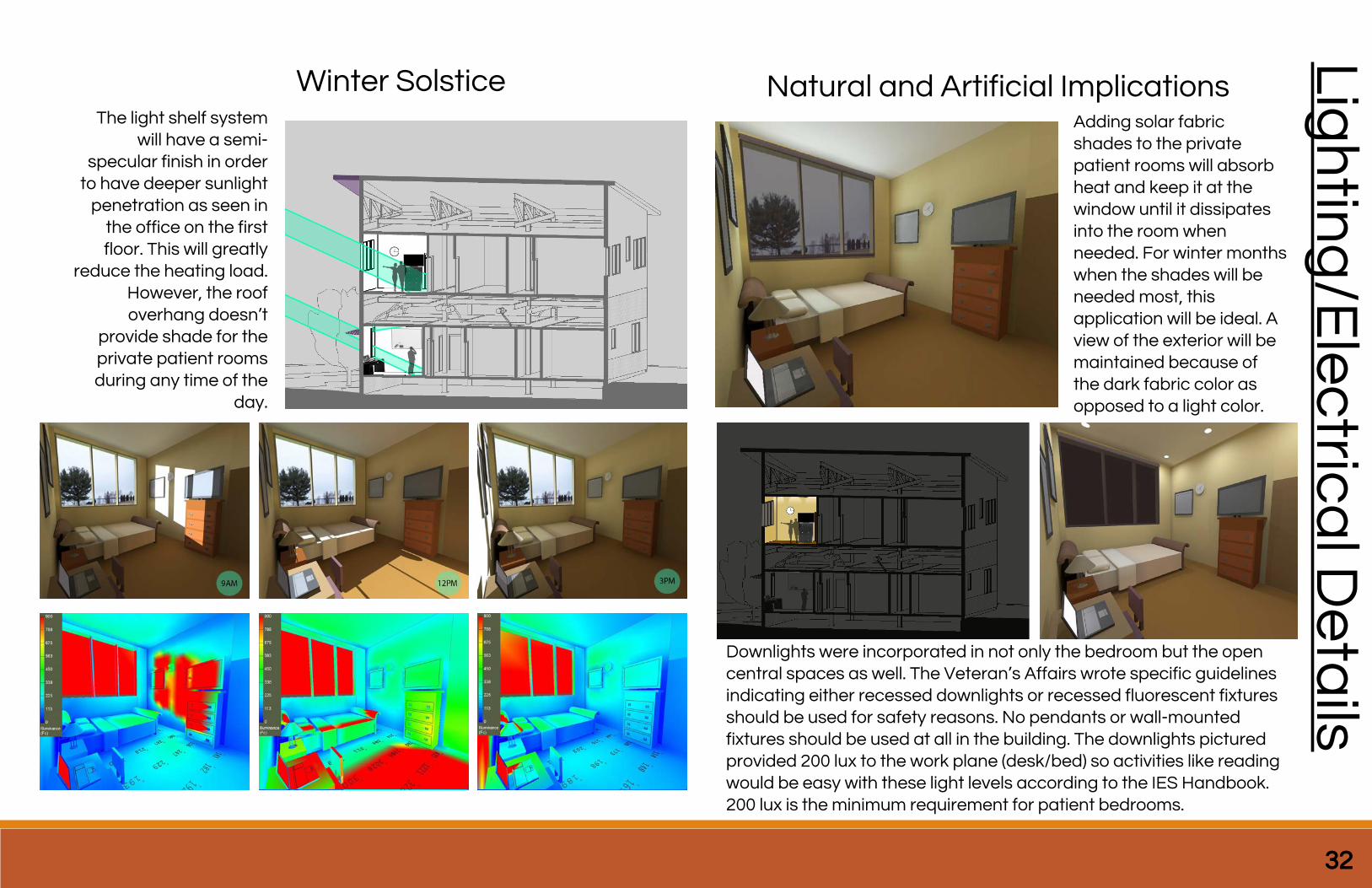
The light shelf system will have a semi-
specular finish in order to have deeper sunlight
penetration as seen in the office on the first floor. This will greatly
reduce the heating load. However, the roof overhang doesn’t
provide shade for the private patient rooms during any time of the
day.
Lig
htin
g/E
lec
trica
l De
tails
Winter Solstice Natural and Artificial ImplicationsAdding solar fabric shades to the private patient rooms will absorb heat and keep it at the window until it dissipates into the room when needed. For winter months when the shades will be needed most, this application will be ideal. A view of the exterior will be maintained because of the dark fabric color as opposed to a light color.
Downlights were incorporated in not only the bedroom but the open central spaces as well. The Veteran’s Affairs wrote specific guidelines indicating either recessed downlights or recessed fluorescent fixtures should be used for safety reasons. No pendants or wall-mounted fixtures should be used at all in the building. The downlights pictured provided 200 lux to the work plane (desk/bed) so activities like reading would be easy with these light levels according to the IES Handbook. 200 lux is the minimum requirement for patient bedrooms.
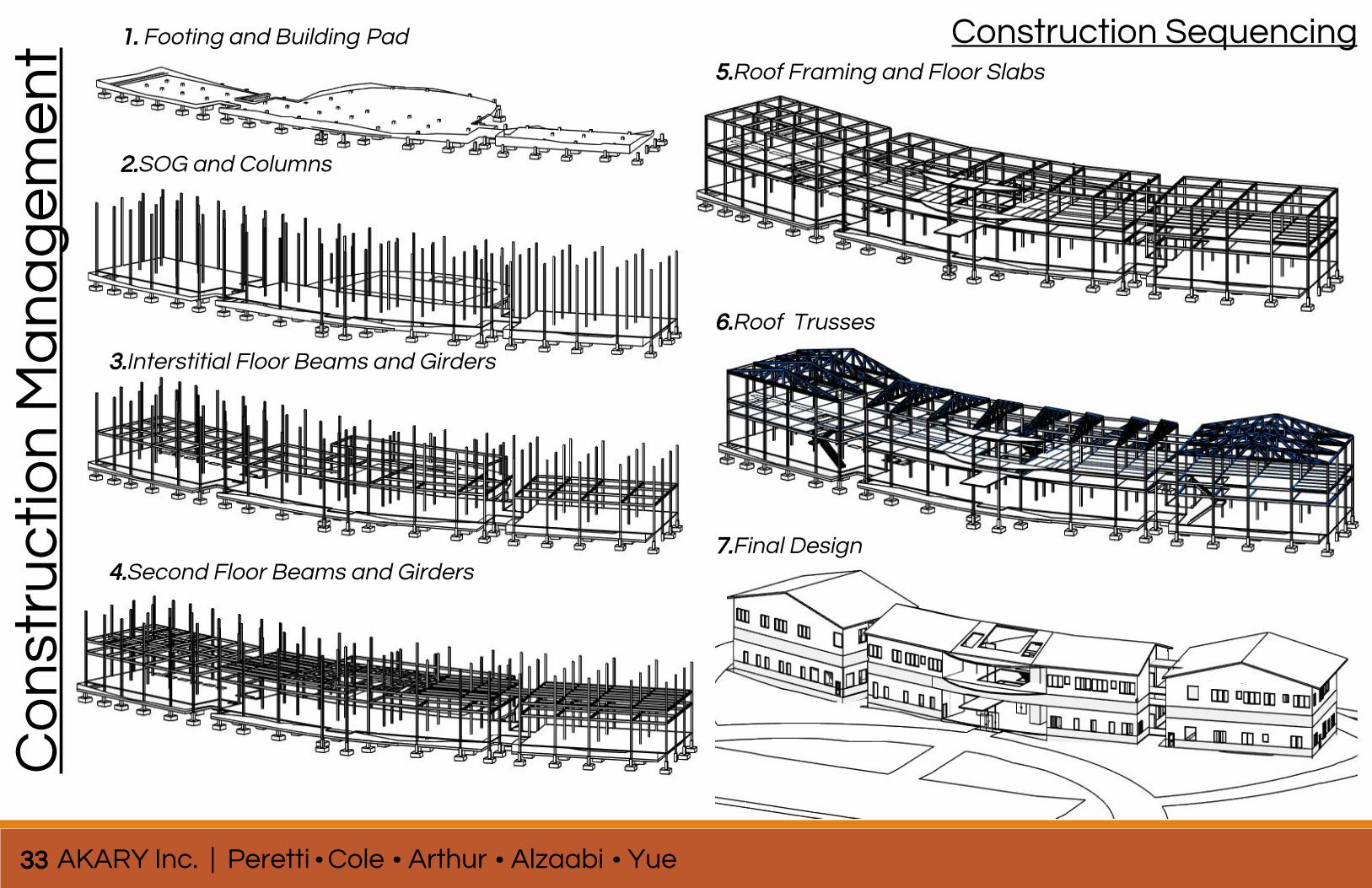
Construction SequencingC
on
stru
cti
on
Ma
na
ge
me
nt 1. Footing and Building Pad
2.SOG and Columns
3.Interstitial Floor Beams and Girders
4.Second Floor Beams and Girders
5.Roof Framing and Floor Slabs
6.Roof Trusses
7.Final Design
33 AKARY Inc. | Peretti Cole Arthur Alzaabi Yue
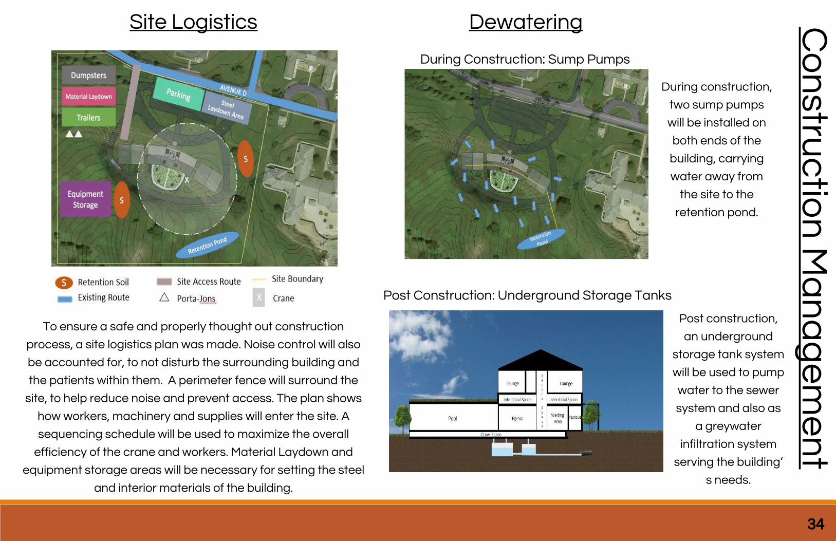
Site Logistics Dewatering
During Construction: Sump Pumps
Post Construction: Underground Storage Tanks
During construction,
two sump pumps
will be installed on
both ends of the
building, carrying
water away from
the site to the
retention pond.
Post construction,
an underground
storage tank system
will be used to pump
water to the sewer
system and also as
a greywater
infiltration system
serving the building’
s needs.
To ensure a safe and properly thought out construction
process, a site logistics plan was made. Noise control will also
be accounted for, to not disturb the surrounding building and
the patients within them. A perimeter fence will surround the
site, to help reduce noise and prevent access. The plan shows
how workers, machinery and supplies will enter the site. A
sequencing schedule will be used to maximize the overall
efficiency of the crane and workers. Material Laydown and
equipment storage areas will be necessary for setting the steel
and interior materials of the building.
34
Co
nstru
ctio
n M
an
ag
em
en
t
Co
nst
ruc
tio
n M
an
ag
em
en
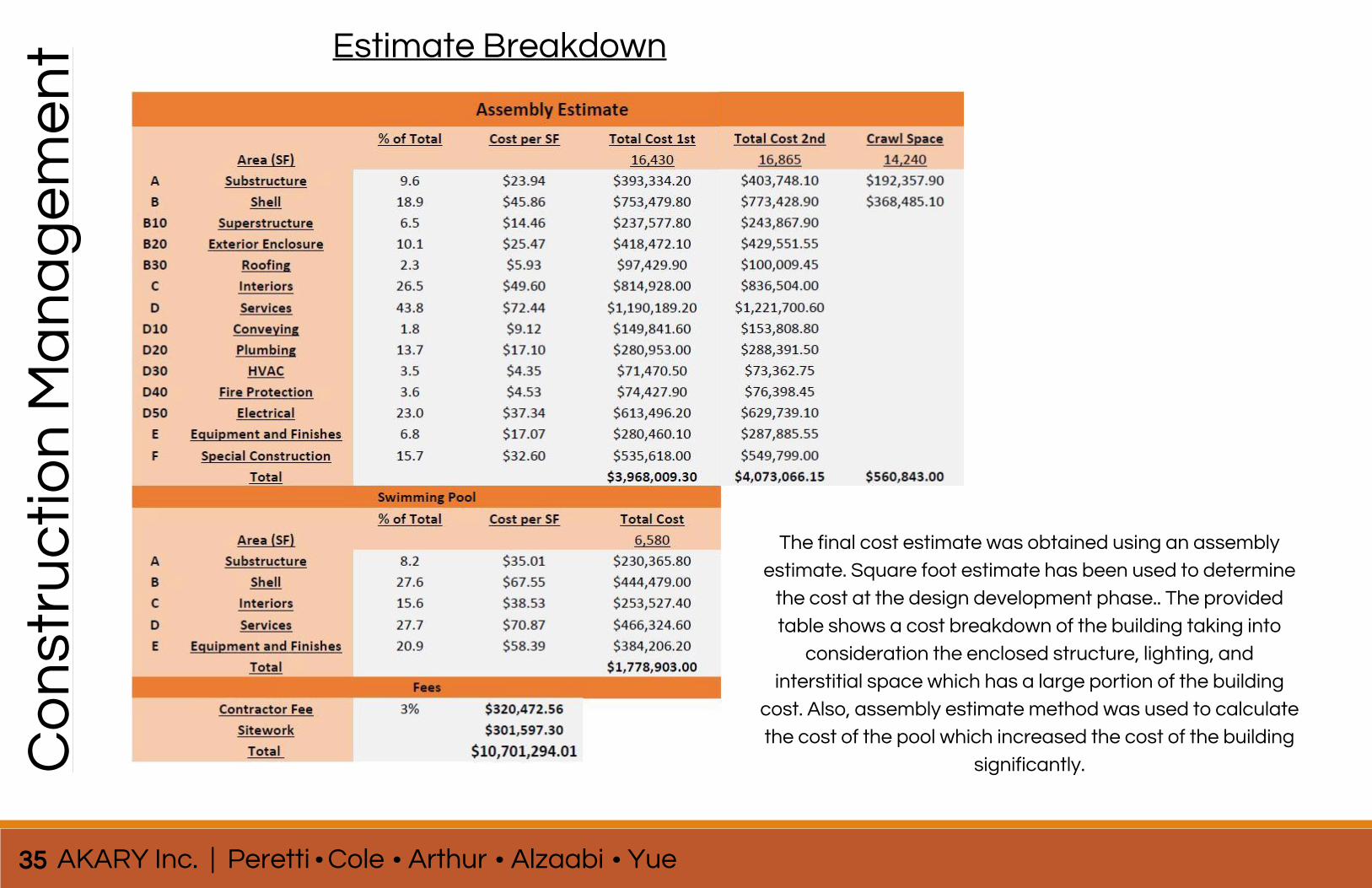
t Estimate Breakdown
35 AKARY Inc. | Peretti Cole Arthur Alzaabi Yue
The final cost estimate was obtained using an assembly
estimate. Square foot estimate has been used to determine
the cost at the design development phase.. The provided
table shows a cost breakdown of the building taking into
consideration the enclosed structure, lighting, and
interstitial space which has a large portion of the building
cost. Also, assembly estimate method was used to calculate
the cost of the pool which increased the cost of the building
significantly.
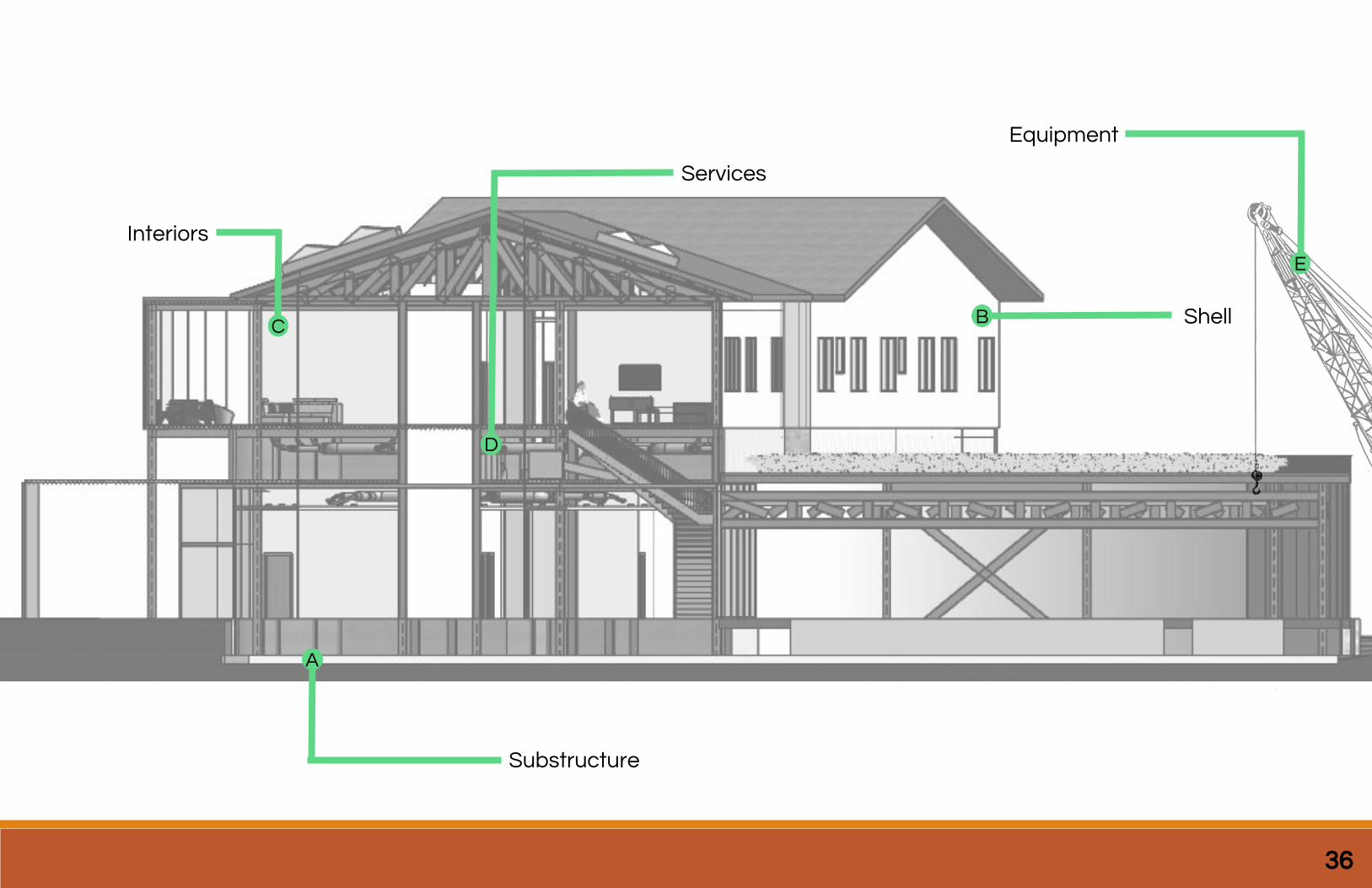
36
Substructure
Shell
Interiors
Services
A
BC
D
Equipment
E
Four Images to show what’s to come
37 AKARY Inc. | Peretti Cole Arthur Alzaabi Yue
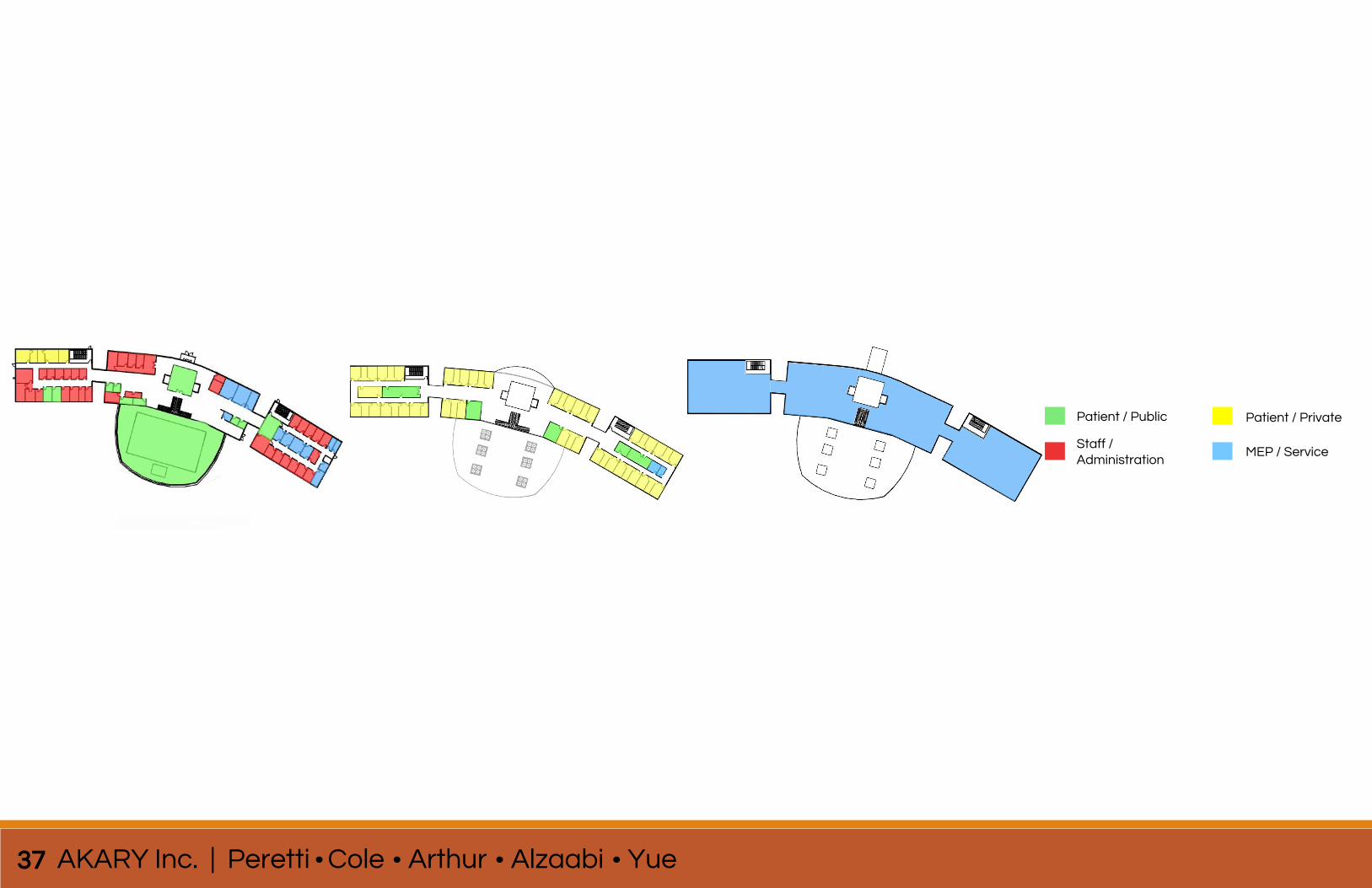
Patient / Public
Staff / Administration
Patient / Private
MEP / Service

Analyses
38
Se
co
nd
Flo
or
Pla
nF
irst
Flo
or
Pla
n
Inte
rsti
tia
l P
lan
Ro
of
Pla
n
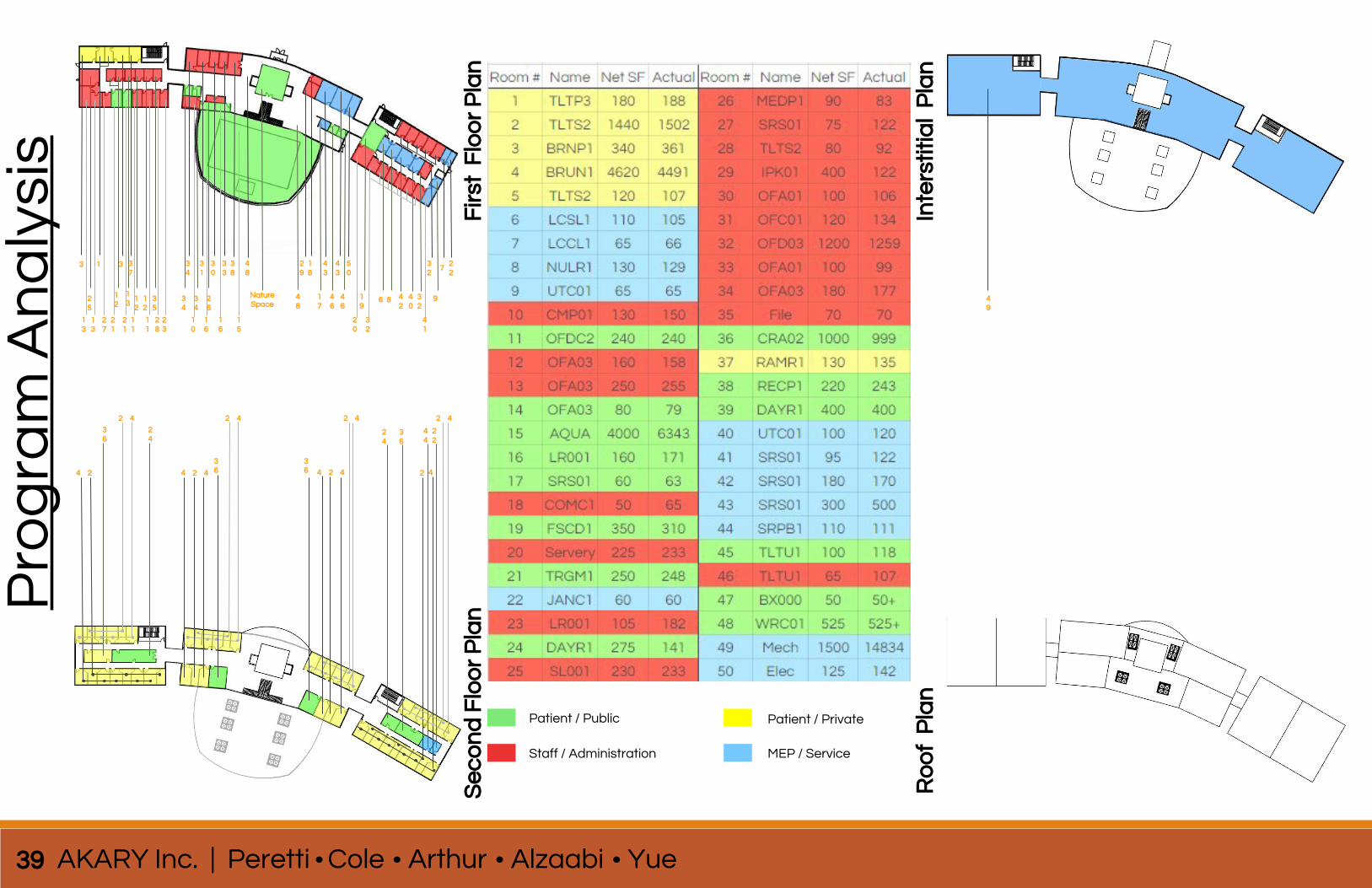
Patient / Public
Staff / Administration
Patient / Private
MEP / Service
13 3 37
25
12
12
35
21
21
11
11
28
23
34
31
30
33
38
34
46
46
34
26
10
16
16
15
Nature Space
29
18
43
43
50
17
20
19
32
6 8 42
40
32
41
32
722
27
13
12
13
13
9
48
48
4 2
36
2 4
4 2 4
24
2 4 2 4 2 4
36
36 4 2 4
36
24
2 4
44
22
49
Pro
gra
m A
na
lysi
s
39 AKARY Inc. | Peretti Cole Arthur Alzaabi Yue
code and life safety provisions
40
Co
de
an
d L
ife S
afe
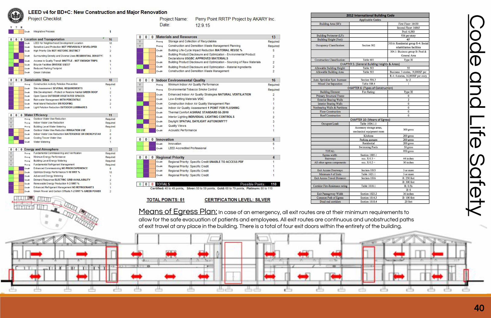
ty Means of Egress Plan: In case of an emergency, all exit routes are at their minimum requirements to
allow for the safe evacuation of patients and employees. All exit routes are continuous and unobstructed paths of exit travel at any place in the building. There is a total of four exit doors within the entirety of the building.
41 AKARY Inc. | Peretti Cole Arthur Alzaabi Yue
summary conclusion
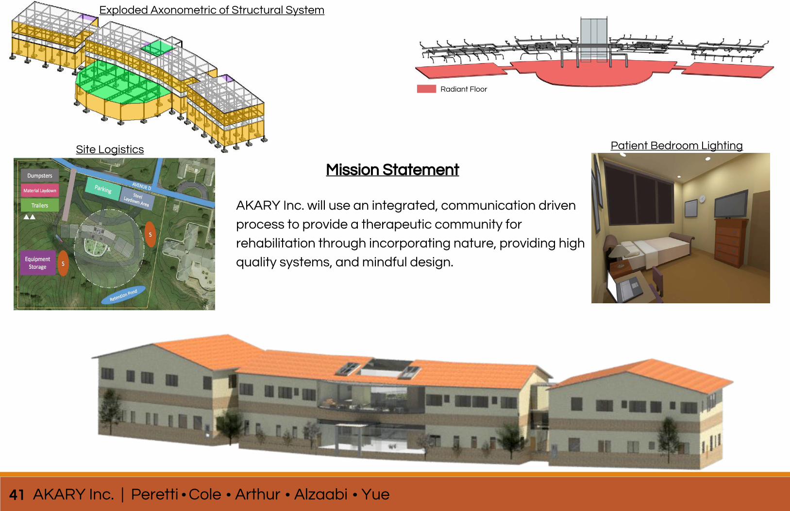
AKARY Inc. will use an integrated, communication driven
process to provide a therapeutic community for
rehabilitation through incorporating nature, providing high
quality systems, and mindful design.
Mission Statement
Radiant Floor
Exploded Axonometric of Structural System
Site Logistics Patient Bedroom Lighting

CD Slotnote that mentions BIM-EX as an appendix
42
Note: BIM EX in Appendix